Embed Size (px)
Citation preview

400
401
MEC
HA
NIC
AL
ENG
INEE
RIN
GP
hD Y
earb
ook
| 201
2
Chair:Prof. Bianca M. Colosimo
Mechanics is one of the leading and driving sectors of industrial manufacturing in Italy. Our country features one of the strongest economies by GDP, being ranked 8th on a worldwide scale (International Monetary Fund, 2011). In terms of per-capita manufacturing production, Italy holds a strong 4th position in the world, and ranks 2nd in Europe (Confindustria, 2010).
In this competitive scenario, and in order to respond to the requests of a challenging sector, our PhD Program, organized within the Department of Mechanics, aims at providing PhD candidates with specific training in Mechanical Engineering by strengthening their research and problem-solving abilities in industrial and academic contexts.
In particular, we emphasize issues of continuous improvement of interdisciplinary education and integration of procedures, ranging from conception to realization. A PhD candidate in Mechanical Engineering follows a path that includes studying activities, research, lab experience, active cooperation with industries, foreign institutions and international research groups. With this background, our Doctorates are able to blend the exactness of scientific knowledge with the ability to deal with practical industrial problems. In this view, their scientific profiles are suitable for prestigious positions at national and international level within industrial companies, consulting companies, universities and research institutions. Our Program numbers about 30 candidates per year.
RESEARCH AREASThe PhD Program in Mechanical Engineering covers a number of different disciplines, being devoted, in particular, to innovation and experimental activities in six major research areas: Dynamics and vibration of mechanical systems and vehicles: this research line is organized into five research areas, namely Mechatronics and Robotics, Rotordynamics, Wind Engineering, Road Vehicle Dynamics, Railway Dynamics. It covers modelling of linear and non-linear dynamic systems, stability and self excited vibrations, active control of mechanical systems, condition monitoring and diagnostics.Measurements and experimental Techniques: the Mechanical and Thermal Measurements (MTM) group has its common background in the development and qualification of new measurements techniques as well as in the customisation and application of well-known measurement principles in innovative fields. The MTM research focuses are the design, development and metrological characterisation of measurement
DOCTORAL PROGRAM IN MECHANICAL ENGINEERING
systems and procedures, the implementation of innovative techniques in sound/vibrations, structural health monitoring, vision, space and rehabilitation measurements.Machine and vehicle design: this research area is involved in advanced design methods and fitness for purpose of mechanical components. Advanced design methods refer to the definition of multiaxial low and high cycle fatigue life prediction criteria, and the assessment of structural integrity of cracked elements, the prediction of fatigue life criteria of advanced materials as polymer matrix composite materials (short and long fibres), the definition of approaches to predict the influence of shot peening on fatigue strength of mechanical components. Gears, pressure vessels and helicopter components are dealt with. The optimal design and the testing of vehicle systems create a synergism between the theoretical and the experimental researches on ground vehicles.Manufacturing and Production Systems: this research field gives relevance to the problem of optimal transformation of raw materials into final products addressing all the issues related with the introduction, usage, and evolution of technologies and production systems during the entire product life cycle. Ph.D. activities can specifically focus on one of the following research fields: Manufacturing
Processes (MPR); Manufacturing Systems and Quality (MSQ). Materials: this area is focused on the study of production process and characterization of materials for structural and functional applications. Excellent research products were obtained both on fundamental research topics (e.g. nanostructured materials, foamed alloys, chemical phenomena in liquid melts, microstructural design ecc.) and on applied research (e.g. failure and damage analysis, texture analysis, high temperature behaviour, coatings for advanced applications, etc.). The research projects carried out in recent years addressed the activities on three main research topics such as Steelmaking and Metallurgical Processes, Advanced Materials and Applied Metallurgy.Methods and Tools for Product Design: research in this field is organized in two main research topics, PLM-Product Lifecycle Management, that includes process modelling, engineering knowledge management, product innovation methods, systematic innovation principles and methods, topology optimization systems, and data/process interoperability, and Virtual Prototyping that includes virtual prototyping for functional and ergonomics product validation, haptic interfaces and interaction, reverse engineering and physics-based modelling and simulation, emotional engineering.
402
403
MEC
HA
NIC
AL
ENG
INEE
RIN
GP
hD Y
earb
ook
| 201
2
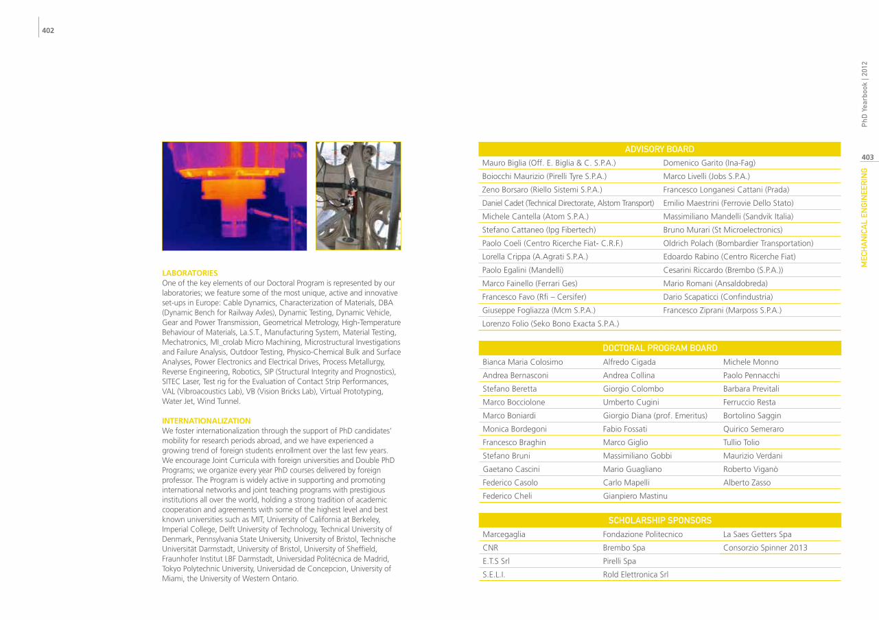
LABORATORIESOne of the key elements of our Doctoral Program is represented by our laboratories; we feature some of the most unique, active and innovative set-ups in Europe: Cable Dynamics, Characterization of Materials, DBA (Dynamic Bench for Railway Axles), Dynamic Testing, Dynamic Vehicle, Gear and Power Transmission, Geometrical Metrology, High-Temperature Behaviour of Materials, La.S.T., Manufacturing System, Material Testing, Mechatronics, MI_crolab Micro Machining, Microstructural Investigations and Failure Analysis, Outdoor Testing, Physico-Chemical Bulk and Surface Analyses, Power Electronics and Electrical Drives, Process Metallurgy, Reverse Engineering, Robotics, SIP (Structural Integrity and Prognostics), SITEC Laser, Test rig for the Evaluation of Contact Strip Performances, VAL (Vibroacoustics Lab), VB (Vision Bricks Lab), Virtual Prototyping, Water Jet, Wind Tunnel.
INTERNATIONALIZATIONWe foster internationalization through the support of PhD candidates’ mobility for research periods abroad, and we have experienced a growing trend of foreign students enrollment over the last few years. We encourage Joint Curricula with foreign universities and Double PhD Programs; we organize every year PhD courses delivered by foreign professor. The Program is widely active in supporting and promoting international networks and joint teaching programs with prestigious institutions all over the world, holding a strong tradition of academic cooperation and agreements with some of the highest level and best known universities such as MIT, University of California at Berkeley, Imperial College, Delft University of Technology, Technical University of Denmark, Pennsylvania State University, University of Bristol, Technische Universität Darmstadt, University of Bristol, University of Sheffield, Fraunhofer Institut LBF Darmstadt, Universidad Politécnica de Madrid, Tokyo Polytechnic University, Universidad de Concepcion, University of Miami, the University of Western Ontario.
ADvIsORy BOARDMauro Biglia (Off. E. Biglia & C. S.P.A.) Domenico Garito (Ina-Fag)
Boiocchi Maurizio (Pirelli Tyre S.P.A.) Marco Livelli (Jobs S.P.A.)
Zeno Borsaro (Riello Sistemi S.P.A.) Francesco Longanesi Cattani (Prada)
Daniel Cadet (Technical Directorate, Alstom Transport) Emilio Maestrini (Ferrovie Dello Stato)
Michele Cantella (Atom S.P.A.) Massimiliano Mandelli (Sandvik Italia)
Stefano Cattaneo (Ipg Fibertech) Bruno Murari (St Microelectronics)
Paolo Coeli (Centro Ricerche Fiat- C.R.F.) Oldrich Polach (Bombardier Transportation)
Lorella Crippa (A.Agrati S.P.A.) Edoardo Rabino (Centro Ricerche Fiat)
Paolo Egalini (Mandelli) Cesarini Riccardo (Brembo (S.P.A.))
Marco Fainello (Ferrari Ges) Mario Romani (Ansaldobreda)
Francesco Favo (Rfi – Cersifer) Dario Scapaticci (Confindustria)
Giuseppe Fogliazza (Mcm S.P.A.) Francesco Ziprani (Marposs S.P.A.)
Lorenzo Folio (Seko Bono Exacta S.P.A.)
DOCTORAL PROGRAM BOARD
Bianca Maria Colosimo Alfredo Cigada Michele Monno
Andrea Bernasconi Andrea Collina Paolo Pennacchi
Stefano Beretta Giorgio Colombo Barbara Previtali
Marco Bocciolone Umberto Cugini Ferruccio Resta
Marco Boniardi Giorgio Diana (prof. Emeritus) Bortolino Saggin
Monica Bordegoni Fabio Fossati Quirico Semeraro
Francesco Braghin Marco Giglio Tullio Tolio
Stefano Bruni Massimiliano Gobbi Maurizio Verdani
Gaetano Cascini Mario Guagliano Roberto Viganò
Federico Casolo Carlo Mapelli Alberto Zasso
Federico Cheli Gianpiero Mastinu
sCHOLARsHIP sPONsORs
Marcegaglia Fondazione Politecnico La Saes Getters Spa
CNR Brembo Spa Consorzio Spinner 2013
E.T.S Srl Pirelli Spa
S.E.L.I. Rold Elettronica Srl
404
405
MEC
HA
NIC
AL
ENG
INEE
RIN
GP
hD Y
earb
ook
| 201
2ANALysIs Of THE OuTPuT vARIABILITy IN MuLTI-sTAGE MANufACTuRING sysTEMs
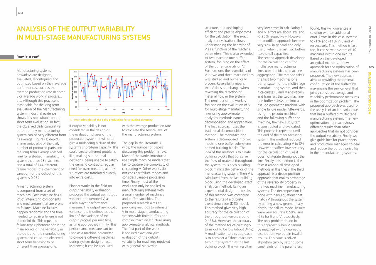
Manufacturing systems nowadays are designed, evaluated, reconfigured and optimized based on their average performances, such as the average production rate denoted E or average work in process...etc. Although this practice is reasonable for the long term evaluation of the Manufacturing system, industrial evidence shows it is not suitable for the short term evaluation. In fact, the observed daily cumulative output of any manufacturing system can be very different from its average. Figure (1) depicts a time series plot of the daily number of produced parts and the long term average (dashed line) for a studied manufacturing system that has 23 machines and a total of 144 different failure modes, the coefficient of variation for the output of this system is 0.264.
A manufacturing system is composed from a set of machines. Each machine has a lot of interacting components and mechanisms that are prone to failures. Machine failures happen randomly and the time needed to repair a failure is not deterministic. This repeated failure-repair phenomenon is the main source of the variability in the output of the manufacturing system and cause the observed short term behavior to be different than average one.
If output variability is not considered in the design or the evaluation phases of the production system, it will often give a misleading picture of the system’s short-term capacity. This could create different problems like; making sub-optimal decisions, being unable to satisfy the demand contracts, regular need for overtime...etc, all these situations are translated directly into extra costs.
Pioneer works in the field on output variability evaluation, proposed the output asymptotic variance rate denoted V, as a releDvaynt performance measure. The output asymptotic variance rate is defined as the limit of the variance of the output process per unit time, as time approaches infinity. This performance measure can be used as a machine parameter to compare different machines during system design phase. Moreover, it can be also used
with the average production rate to calculate the service level of the manufacturing system.
The gap in the literature is wide; the number of papers discussing this problem is few. Most of the works introduced use simple machine models that fail to capture the complexity of calculating V. Other works do not consider failure modes and considers variable processing time. Finally most of the works can only be applied to manufacturing systems with a small number of machines and buffer capacities. The proposed research aims at providing methods to estimate V in multi-stage manufacturing systems with finite buffers and complex machine structure using approximate analytical methods.The first part of the work is focused exact analytical evaluation of the output variability for machines modeled with general Markovian
Ramiz Assaf
1. Time series plot of the daily production for a studied company
structure, and developing efficient and precise algorithms for the calculation. The exact analytical evaluation allows understanding the behavior of V as a function of the machine parameters. This is also extended to two machine one buffer system, focusing on the effect of the buffer capacity on V. Furthermore, the reversibility of V in two and three machine lines was studied and numerically proven. Reversibility means that V does not change when reversing the direction of material flow in the system.The reminder of the work is focused on the evaluation of V for multi-stage manufacturing lines using approximate analytical methods namely, decomposition and aggregation. The first approach uses the traditional decomposition method. The manufacturing system is decomposed into two machine one buffer subsystems named building blocks. The idea of this method is to create building blocks that conserve the flow of material throughout the system, thus each building block mimics the behavior of the manufacturing system. Then V is calculated from the last building block using the developed exact analytical method. Using an experimental design the results of this method was compared to the results of a discrete event simulation (DES) model. This method gives very high accuracy for the calculation of the throughput (errors around 0.46%). However, the accuracy of the method for calculating V turns out to be low (about 34%). A modification to this approach is to consider a “three machines two buffer system” as the last building block. This will result in
very low errors in calculating E and V, errors are about 1% and -5.25% respectively. However the modified approach becomes very slow in general and only useful when the last two buffers have small capacities.The second approach developed for the calculation of V for multistage manufacturing lines uses the idea of machine aggregation. The method takes the first two machines-one buffer system of the multi-stage manufacturing system, and then it calculates E and V analytically and transfers the two machine-one buffer subsystem into a pseudo geometric machine with single failure mode. Afterwards, using the pseudo machine and the following buffer and machine, the new subsystem is constructed and evaluated. This process is repeated until the end of the manufacturing system. This method reduced the error in calculating V to 8%. However it suffers low accuracy for the calculation of E as it does not iterate throughout the line. Finally, this method is the fastest among all developed methods in this thesis.The third approach is a decomposition approach that makes advantage of the reversibility property in the two machine manufacturing systems. The decomposition is done with new equations that match V throughout the system, by adding a new geometrically distributed failure mode. Results were very accurate 0.59% and -5% for E and V respectively. The only problem found in this approach when V cannot be matched with a geometric distribution, we obtain invalid results. This issue is solved algorithmically by setting some constraints on the parameters
found, this will guarantee a solution with an additional error. Errors in this case increase to -1% and -11% in E and V respectively. This method is fast too, it can solve a system of 10 machines within one minute.Based on the developed analytical methods, a new approach for the optimization of manufacturing systems has been proposed. The new approach aims at providing the optimal configuration of the buffers by maximizing the service level that jointly considers average and variability performance measures in the optimization problem. The proposed approach was used for the analysis of an industrial case, that has a buffered multi-stage manufacturing system. The new optimization approach shows different results than other approaches that do not consider the output variability. Finally we give guidelines for practitioners and production managers to deal and reduce the output variability in their manufacturing systems.

406
407
MEC
HA
NIC
AL
ENG
INEE
RIN
GP
hD Y
earb
ook
| 201
2HyDRODyNAMIC sTuDy Of fLOws INsIDE ABRAsIvE wATER jET CuTTING HEAD
Abrasive water jet (AWJ) makes use of a high velocity slurry jet, while in the pure water jet (PWJ) the high velocity water jet emerging from an orifice is used as a cutting tool. Inside the cutting head, there is a large-scale of turbulence mixing and momentum transfer that takes place. This results in a situation where the jet exiting the cutting head acts as the cutting tool eroding the material without heating, thus, a cold cutting process.AWJ cutting has passed through great stride over the past 30 years. The developments have succeeded in bringing the technology to a rival with other cutting technologies such as laser cutting and plasma cutting in such a short time. This challenge is continual as the potential of this process is continued to be exploited. Yet, process conditions (jet characteristics) are still unpredictable to a large extent and this impedes a difficulty in the development. These bases on the insufficient knowledge of the associated characteristics of a cutting head operation and absence of the comprehensive understanding of its flow characteristics. Consequently, a certain driving motivation arouses on the study of the existing cutting heads before developing new systems and accordingly advances in the research. The present work
is focused on the study of the cutting head flows associated with the idea of creating tools to develop the research on cutting head flows by studying the three phase flow phenomena by numerical and experimental methodology. The analysis in the thesis work starts with a conceptual review of the abrasive water jet cutting head from different aspects. A detailed component based analysis of the cutting head is a subject of the thesis.In the first part of the study, the flow through water jet orifices was studied. Its study was important to understand the effect of the internal geometries of orifices on the jet characteristics. In this study, Computational Fluid Dynamics (CFD) simulation was performed to improve the understanding of water jet formation and fluid flow process through the orifice under high injection pressures. In particular, water jet formation and reattachment length in sharp edged diamond orifices were studied. The investigation used a two dimensional, axisimetric, two-phase, transient-state model of orifice flow to observe the effects of capillary length and diameter on the jet break-up length. The injection pressure was varied from 10 MPa to 700 MPa. Results are presented for two standard diamond orifice types.
In the second part of the study, jet stability and effect of droplets collisions inside an orifice where studied. The internal geometry of the orifice plays an important role during the first instants of the jet creation affecting the jet break-up and the creation of droplets which remain inside the orifice sticking or rebounding on the walls of the orifice exit tube.A CFD analysis is carried out to study the effect of the droplet collision with the main jet: the jet break-up, early presence of water, condensed humidity or jet disturbances can create these water droplets which then can be dragged by the high velocity air field created inside the orifice tube by the main water jet (Figure 1). Droplets can later collide along the main jet or be sucked up towards the capillary (the upper small orifice hole where the jet is created) causing local disturbances and loss of the hydraulic flip condition which is crucial for the coherence of the jet. This random process effectively explains the instabilities which can usually be noticed by a naked-eye observation during the water jet formation and later on; the study of this phenomenon can lead to new instruments for an improved design of water jet cutting head components on the way to high precision applications. The results of simulations are validated by means of a high-speed camera.
Amanuel Tesgera Basha (Manufacturing and Production Systems)
The third part of the study deals with, the effect of water jet orifice housing geometry downstream of the orifice on the stability of a pure water jet. It is presented with a view to enhance the performance of contour cutting of foam materials in the seals and gaskets industry. CFD analysis is performed and it is found that the velocity magnitude and coherence of the jet is dependent on the geometry of orifice housing. The CFD results
are compared with imaging experiments and previous work obtaining good agreement. A factorial experimental work is then developed. The results show that the geometry of orifice housing plays an important role in the accurate contour cutting of the foam material.The last part is dedicated to the discussion of the detail of flows in side abrasive water jet cutting heads. Cutting heads are critical components affecting the cutting performance of abrasive
water jet (AWJ) technology. Therefore, investigating their characteristics to achieve efficient design is fundamental to improve this technology. In this study, Computational fluid dynamics (CFD) models for ultrahigh velocity water jets and abrasive water jets (AWJs) are established using ANSYS FLUENT software. Jet flow dynamic characteristics inside a cutting head are simulated under unsteady state, turbulent, two-phase and three-phase flow conditions. Water and particle velocities in a jet are obtained under different operating conditions to provide an insight into the jet characteristics and study the effect of cutting head geometry.The comparison with own experimental (Figure 2) data shows the accuracy of the numerical simulations in predicting cutting head performance, as well as revealing the effect of operating conditions. Besides, it is found that the flow pattern does not depend much on the position of the abrasive and air suction zone. This investigation aids the understanding of the flow inside AWJ cutting head and provides information for designing these components to suit optimum performances. Consequent CFD results include detailed flow profiling through path line tools, pressure and velocity evolution.
1. Path lines of air inside orifice tube colored by velocity magnitude [m/s].
2. Sensorized transparent cutting head.
408
409
MEC
HA
NIC
AL
ENG
INEE
RIN
GP
hD Y
earb
ook
| 201
2ACTIvE vIBRATION CONTROL fOR fLExIBLE sTRuCTuREs
The last years were characterized by a wide development of large flexible structures in mechanical and aerospace fields thanks to the large use of lightweight materials such as carbon fiber.Flexible structures are often characterized by low damping ratio and, as a consequence, high sensitivity to external disturbance forces causing high vibration levels and high mechanical stresses. For this reason active control is a very attractive solution to suppress structure vibrations and to reduce problems related to damage and safety.Typically every active control strategy for vibration suppression involves a series of topics:The measurement or identification of the system vibratory state;The definition of the control algorithm;The actuation of the control force on the structure.The present PhD thesis deals with the study of new solutions for vibration control of flexible structures, focusing, in particular, on the first two points.Structural vibrations depend on the dynamic characteristics of the structure and on the input forces acting on it. For this reason, a control logic can be designed so that it modifies the dynamic properties (typically increasing damping) or it compensates the external forces, reducing their effect on the structure. In the present work both the possible
strategies have been investigated.Considering the first control family, modal space controllers, and in particular resonant controls are very interesting, since they allow, under certain assumption, to independently control each system mode, modifying the dynamic properties associated with it. In this sense each vibration mode of the system under investigation can be analyzed as a single degree-of-freedom system. For each mode, resonant control logics calculate the feedback action through a dynamical system, typically a first or second order compensator. It returns a control force that, at the resonance frequencies under investigation, is in opposition of phase with respect to the modal velocity and so it produces a damping effect on the correspondent vibration modes.In the present PhD thesis, first the most common state-of-the-art resonant control techniques
(Independent Modal Space Control and Positive Position Feedback) have been analyzed. Then two new solutions have been proposed to improve the performances of resonant control for vibration suppression. The first one, called Active Modal Tuned Mass Damper (AMTMD) is a resonant controller which formulation is based on the classical passive Tuned Mass Damper. The second one, called Negative Derivative Feedback (NDF), is based on a second order compensator designed to be a band-pass filter. Thanks to this formulation, NDF is able to outperform the state of the art resonant control techniques, since it is more robust to spillover problems both for frequencies higher and lower than the considered ones and it avoids unwanted vibration amplifications typical, for example, of PPF. The proposed control strategies have been tested both numerically
Gabriele Cazzulani
+
0 1 2 3 4 5 6 710-2
10-1
100
101
Ampl
itude
[m/(s
2 *mm
)]Frequency [Hz]
No controlIMSCIMSC + DE
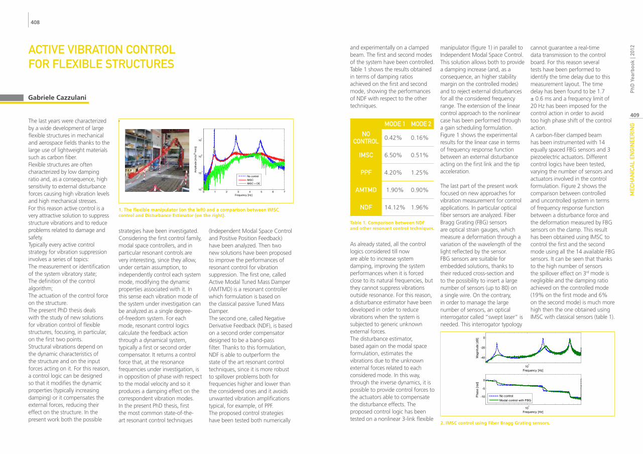
1. The flexible manipulator (on the left) and a comparison between IMSC control and Disturbance Estimator (on the right).
and experimentally on a clamped beam. The first and second modes of the system have been controlled. Table 1 shows the results obtained in terms of damping ratios achieved on the first and second mode, showing the performances of NDF with respect to the other techniques.
As already stated, all the control logics considered till now are able to increase system damping, improving the system performances when it is forced close to its natural frequencies, but they cannot suppress vibrations outside resonance. For this reason, a disturbance estimator have been developed in order to reduce vibrations when the system is subjected to generic unknown external forces.The disturbance estimator, based again on the modal space formulation, estimates the vibrations due to the unknown external forces related to each considered mode. In this way, through the inverse dynamics, it is possible to provide control forces to the actuators able to compensate the disturbance effects. The proposed control logic has been tested on a nonlinear 3-link flexible
manipulator (figure 1) in parallel to Independent Modal Space Control. This solution allows both to provide a damping increase (and, as a consequence, an higher stability margin on the controlled modes) and to reject external disturbances for all the considered frequency range. The extension of the linear control approach to the nonlinear case has been performed through a gain scheduling formulation. Figure 1 shows the experimental results for the linear case in terms of frequency response function between an external disturbance acting on the first link and the tip acceleration.
The last part of the present work focused on new approaches for vibration measurement for control applications. In particular optical fiber sensors are analyzed. Fiber Bragg Grating (FBG) sensors are optical strain gauges, which measure a deformation through a variation of the wavelength of the light reflected by the sensor.FBG sensors are suitable for embedded solutions, thanks to their reduced cross-section and to the possibility to insert a large number of sensors (up to 80) on a single wire. On the contrary, in order to manage the large number of sensors, an optical interrogator called “swept laser” is needed. This interrogator typology
cannot guarantee a real-time data transmission to the control board. For this reason several tests have been performed to identify the time delay due to this measurement layout. The time delay has been found to be 1.7 ± 0.6 ms and a frequency limit of 20 Hz has been imposed for the control action in order to avoid too high phase shift of the control action.A carbon-fiber clamped beam has been instrumented with 14 equally spaced FBG sensors and 3 piezoelectric actuators. Different control logics have been tested, varying the number of sensors and actuators involved in the control formulation. Figure 2 shows the comparison between controlled and uncontrolled system in terms of frequency response function between a disturbance force and the deformation measured by FBG sensors on the clamp. This result has been obtained using IMSC to control the first and the second mode using all the 14 available FBG sensors. It can be seen that thanks to the high number of sensors the spillover effect on 3rd mode is negligible and the damping ratio achieved on the controlled mode (19% on the first mode and 6% on the second mode) is much more high then the one obtained using IMSC with classical sensors (table 1).
101
-40
-20
0
Frequency [Hz]
Mag
nitu
de [d
B]
101
-10
-5
0
Frequency [Hz]
Phas
e [ra
d]
No controlModal control with FBG
2. IMSC control using Fiber Bragg Grating sensors.
Table 1. Comparison between NDF and other resonant control techniques.
MODE 1 MODE 2
NO CONTROL 0.42% 0.16%
IMsC 6.50% 0.51%
PPf 4.20% 1.25%
AMTMD 1.90% 0.90%
NDf 14.12% 1.96%

410
411
MEC
HA
NIC
AL
ENG
INEE
RIN
GP
hD Y
earb
ook
| 201
2EsTIMATION Of wHEEL-RAIL CONTACT fORCEs
Railway vehicles, during traveling, discharge to the ground forces that allow them to follow the track, through wheel-rail contact. These forces depend on the route, on the dynamic behavior of the train and on the load that the train carries. Usually, the contact forces split into three main directions, so as to identify the vertical, lateral and the longitudinal forces. This information is used to evaluate the safety of travel of the vehicle, to perform diagnosis on both vehicle and line, to develop mathematical models of vehicles and to schedule and verify maintenance on lines; finally, the estimated values of the forces are used in the UNI EN 14363 for homologation of railway vehicles. Various methods of measurement of contact forces have been developed over the years. These methods, basically, focus on the estimation of forces at wheel-rail contact by means of measurement of wheelsets deformations, in various points that can be positioned on the axle or on the wheel web. The measurement of forces is not so straightforward: calibration is needed to obtain forces from the deformation measurements. In addition, several methods of calibration of the wheelsets have also been developed, giving known forces and measures
deformations on selected points of wheelsets that can rotate or be fixed. The work presents a hybrid method for the estimation of contact forces (as integrates the classic measures of deformation with other measures), optimized (in order to obtain a measurement system reliable or inexpensive), which uses the deformations of both the axle and wheel web, and when possible the length of the primary suspension. In addition, the calibration method developed provides the application and the direct measurement of forces on the rail, using the entire wheelset-bogie system, so to maintain the linking conditions between wheelset and bogie during test-rig calibration and in-line measure operations. The system uses a calibration matrix, obtained by Moore-Penrose pseudo-inverse, which, using the signals measured in� traveling, gives the contact forces limited uncertainty.
Pietro Crosio
1. Test-rig calibration operation of a subway train wheelset.
2. Comparison between applied and estimated vertical forces during test-rig calibration.
3. Estimated Nadal coefficent for travel safety.

412
413
MEC
HA
NIC
AL
ENG
INEE
RIN
GP
hD Y
earb
ook
| 201
2MODELING Of TANk vEHICLE DyNAMICs By fLuID sLOsHING COuPLED sIMuLATION
Several studies conducted by national authorities of different countries in the past years report that among the accidents in which heavy vehicle are include the majority of them involve heavy vehicle carrying liquid cargo (National Road Transportation Commission 2002). These accidents represent a cost for the community in terms of health care and infrastructure which can be worsen in case the heavy vehicle carry dangerous goods like gasoline or toxic fluids. The statistic analysis of the accidents turns out that tank trucks exhibits a less stability either in longitudinal than lateral dynamics; During braking maneuvers the displacement of the fluid may lead to the rear wheels locking up due to the load transfers, while during sudden lane change the lateral fluid sloshing can determine the vehicle roll over.
To increase stability of tank trucks many studies have been conducted leading to the tank shape optimization (Craig 2003) and to the introduction of the baffles to reduce the sloshing. However the effectiveness of the solution is strongly related to the reliability of the models used to reproduce the coupled fluid cargo-vehicle dynamics. At that purpose several approaches to study the effect of sloshing
cargoes have been proposed in the literature. In Mantriota 2007 the coupled vehicle fluid dynamics has been simulated by means of a series of pendulum representing the fluid oscillation and connected to the vehicle frame by means of spring-damper elements. Although very effectives, the hard task in these approaches relies on the model parameters identification. Kineto-static fluid models have also been proposed by Ranganathan et.all 1990. These studies shown how kineto-static fluids models can describe very well the motion of the fluid centre of gravity but they do not take into account the amplification forces due to nonlinear sloshing effects. The co-simulation technique, proposed by Rummold 2001, is a possible solution of the coupled vehicle-liquid cargo dynamics. It consists on modeling the two systems separately in two suitable environments, e.g. CFD for the fluid and MBS for the vehicle. During the co-simulation, the CFD fluid model and the MBS vehicle model exchanging inputs/outputs after predefined time steps allowing this way to simulate the mutual interaction.
In this research work, a computational fluid dynamics slosh model is coupled with a multi body truck model.
The CFD model is based on the Navier-Stokes equations incorporating the Volume of Fluid (VOF) technique which allow simulating the interactions between two immiscible fluids by solving a single set of momentum equations and tracking the volume fraction of each of the fluids throughout the domain. The Moving Mesh (MM) technique is used to specify the motion of the tank by providing the linear and angular velocities at every time step. A 14 dofs vehicle model able to simulate the 3 dimensional vehicle dynamics is coupled with the CFD model to evaluate the vehicle behavior during lane change and braking maneuvers.
Simulations have been carried out on an optimized tank shape based on the Reuleaux triangle principle. The influence of baffles and fill levels on lateral and longitudinal dynamics has been investigated in order to find critical condition. Results of braking maneuver simulation allowed to find limit longitudinal acceleration as function of the fill level which leads to the rear wheels lock up. Moreover the effectiveness of the transversal baffles has been investigated, showing how the baffles can improve the brake performance. Results of lane change shown how the fluid motion within
Vincenzo D’Alessandro
the tank can reduce drastically the rollover threshold and thus reduce the road safety. Finally the tilt table test has been simulated, from these results has been observed how tank shape having low ‘Static Rollover Threshold’ in full load condition, the lateral fluid displacement due in partly filled condition can severely reduce the static rollover threshold.
1. Simulation scheme for fluid-vehicle interaction.

414
415
MEC
HA
NIC
AL
ENG
INEE
RIN
GP
hD Y
earb
ook
| 201
2A NEw COMPOuND suRfACE TREATMENT METHOD AIMED TO NANO-sTRuCTuRED COATING
The ever increasing research of lightness, safety and reliability is pushing to look for materials with superior mechanical properties, to meet severe design requirements imposed in many fields. Nanocrystal (NC) materials are experiencing a rapid development in recent years due to their existing potential applications in a wide variety of technology; admittedly, they possess superior mechanical properties by some means different from their conventional coarse grained polycrystalline counterparts. The commercial applications of Nano-materials, beyond the boundaries of laboratories, lie on the successful production and consolidation of these materials into components preserving the Nano-structures.Cold Spray coating (CS) a new innovative deposition technique which uses elements of both physical deposition and severe plastic deformation for growing NC. CS is an emerging coating process in which in contrast to the other thermal spray processes the powders does not melt before impacting the substrate. Bonding of the particles in this process occurs due to the high kinetic energy upon impact; therefore, the velocity of the particle plays the most important role in material deposition. During the process, powders are accelerated by
injection into a high velocity stream of gas. The high velocity stream is generated through a converging-diverging nozzle. On the other hand, Shot peening, by increasing the energy of the surface, usually helps to increase the fatigue life of the structure and coating improve the surface properties. By combing the shot peening with cold spray coating, the advantages of both treatments could be obtained.In the numerical part of the thesis two numerical models have been developed. First is for finding the critical velocity and the second one for studying the peening effect of the coating. It is well recognized that particle velocity prior to impact is a key parameter in CS process. Critical velocity (CV) for a given powder is defined as the velocity that an individual particle must attain in order to deposit after impacting the substrate. Examining the CV experimental is practically almost impossible due to the fact that all the deposition process for a single particle longs less than few nano seconds. A finite element model using commercial Abaqus/Explicit has been developed in order to simulate the phenomenon and broadening the horizon of the physical background of the process. The general agreement supports the idea that shear localization (SL) plays an important role in the
bonding of the particles. By using a material model which is able to model softening phenomenon by considering strain rate in the model, CV, through numerical simulation, has been estimated by finding SL appears in the outputs of the software which are discrete numbers as a singularity in the function. The singularity has been found by transferringthe results in frequency domain using wavelet transform and analyzing the smoothness of the function by calculating the second derivative of the function in Sobolev space. The results for tested material comparing to experimental measurements shows a good correspondence. Another FE model developed in order to examine the peening effect of the particles on the substrate. The peening of the particles induces residual stress and high plastic deformation. The compressive residual stress generally increases the fatigue endurance of the structure and recrystallization can be the result of the high plastic deformation of the sample. In CS, the particle diameter has a Rosin-Rammler distribution; their velocity and temperature are the function of the particle diameter based on the initial condition of the process. The numerical model considers the randomness of the particle in size and position with the appropriate distribution
Ramin Ghelichi
and for each particle, based on its size, uses related velocity and temperature. The results of numerical simulation are in a good agreement with the experimental measurement of the XRD diffraction for residual stress measurement. The FE simulation predict the possibility of the Nano grains on the substrate due to the fact that the equivalent plastic strain caused by particles impact passes the value suggested by scholars as a criterion for decreasing the grain size.The grain size of the coated samples not only on the deposited material but also on the substrate by removing the deposited material has been measured by using the XRD diffraction. The in-situ XRD test machine has been employed to extract the diffraction peaks which are usually used for stress measurements. The Voigt formulation in order to separate
the grain size and micro strain data from the curve is applied on the output of the machine which helped to measure the grain size of the samples. The results approve the prediction of the numerical simulation of the existence of Nano grains on the substrate.The effect of the coating with conventional and Nano structure has been studied by using the specimen suggested by standard. The load control test machine which can satisfy the perquisite requirement of the standard has been developed in the lab; it has been calibrated by using strain gauges and checked the effective distance and frequency. In this regard, different series of samples from different aluminum alloys have been coated by aluminum alloy powders. The results of the fatigue test (Fig.1) shows that the coating, regardless of the deposited material, increases the
fatigue limit of the samples. In the case of deposition of harder material, the fatigue limit will be increased more than the softer ones. In the samples, it is observed that the softer deposition in some cases do not participate in the loading due to some delamination of the deposited material from the substrate. The last tentative, is producing the nano structure by severe shot peening after the coating. It would result having both advantages of coating and shot-peening on the sampels. In this case, the fatigue limit does not increase with respect to the previous samples without shot peening. Although the grain size on the samples after shot peening are less than 100nm, due to existence of the micro cracks and severly deformedsurface of the samples it is not possible to benefit the advantages of the NC to improve the fatigue life.
Finally it can be concluded that, the cold spray coating per se can increase the fatigue life based on the kind of deposited material on the structure. This conclusion might open a new door for a new application for this treatment.
1.

416
417
MEC
HA
NIC
AL
ENG
INEE
RIN
GP
hD Y
earb
ook
| 201
2METAL sPONGEs: PRODuCTION, CHARACTERIzATION AND APPLICATION
Cellular metals are a new class of materials characterized by low densities associated to interesting and novel mechanical-physical-chemical properties. They seem not to comply with the common sense of metal engineering: many scientific efforts are focused on the limitation and at least on the removal of porosity in load-bearing parts. In fact, researchers work hard to eliminate pores from castings, powder metallurgy parts, coatings, weld joints thinking that a defect-free part is a pore- free one. However, large natural structures of porous materials demonstrate how evolution has generated cellular structures that optimize mechanical properties and structural function for minimum weight. Understanding the benefits of natural structures gives us information to develop cellular-solids.
Among man-made cellular materials, polymeric foams are currently the most important ones with widespread applications in nearly every sector of technology. Less known is that even metals and alloys can be produced as cellular materials and these materials have such interesting properties that, exciting new applications, are expected in the near future.In this direction the choice of the proper material is quite important: polymers appear
to be insufficiently rigid and ceramics are too brittle. Metal seems to be a good choice due to the intrinsic metal properties such as good stiffness, thermal resistance, thermal and electrical conductivity and so on. Moreover, metals sponges are fully recyclable: today a very important property of manufactured products.Owing to their pores, cellular metals show a set of unusual properties compared with bulk structural materials: they are crushable, they exhibit a plateau stress in compression and a change in Poisson’s ratio and in stiffness on deformation. The excellent combination of mechanical properties and low weight is the prime advantage. In addition, they absorb a great amount of impact energies and are very efficient in sound absorption, electromagnetic or fire shielding and vibration
dumping. Moreover, cellular solids, featured by interconnected pores, allow the passage of a fluid and the consequent energy exchange with it, important property, for example, in the production of heat exchangers.Most of the mechanical properties of cellular metals can be achieved with other materials, sometimes more efficiently, but foams can offer a unique combination of several properties that cannot be obtained in one conventional material at the same time. Cellular metals are thus promising in applications where several of these functions can be combined.Nowadays, the most common material employed in cellular form is aluminum, due to its suitable melting point and physical properties. However, in literature many working production routes arereported
Andrea Gruttadauria
1. Natural cellular structures: a) cork; b) balsa wood; c) sponge; d) human bone; e) coral; f) cuttlefish bone; g) iris leaf and h) plant stalk.
for a wide range of other metals, such as magnesium, lead, nickel, copper, bronze, titanium, steel and even gold.The aim of the project is to widen even more the range of suitable cellular metals employing the, so called, infiltration process that consists
in infiltrating the molten metal into a inert filler, which is finally removed, leaving behind the desired cellular structure. The work attempts to improve the infiltration process, updating it for high melting temperature metals, such as ferrous alloys and some non-ferrous alloys in between, including shape memory alloys. Obviously, in order to switch to such metals, the project had to deal with an accurate and detailed survey of all the possible suitable fillers, which need to answer to the strict thermal and chemical requirements imposed by the process.Figure 2 shows the different metal sponges obtained by the licensed process and by the updated version. The sponges have been listed as function of the melting temperature and it is important to observe that the metals with a melting
point above 1100 K has been manufactured only by modifying the heating system and using proper materials suitable as space holder. Moreover, the graph is a clear evidence of the versatility of the manufacture procedure regarding both the metals of choice and the final
desired characteristics.The process has been also modified in order to have a better control of the cellular morphology and structure, with the final aim of being able to tailor precisely the sponge properties from the start of the process. In addition, the process efficiency has been also tested by investigating both morphological and mechanical properties.Once the process has been suitably set up, the study focuses on the characterization of the products in order to correlate the mechanical properties to the morphological features of the materials that depend on the process parameters. Concluded the characterization, the study turns back to the main process with the intent of tuning the production technique with the suitable sponge parameters. Indeed, currently metal sponges are incompletely characterized
and the process routes are imperfectly controlled, resulting in some properties variability. Neglecting this important passage would mean losing a wider range of properties. Above all, one the first concerns of the work is to expand as much as possible the range of available products and properties in view of a wider window of future applications.The designed manufacturing route has been proven to be extremely successful for the production of metal sponges with outstanding results in terms of morphological characteristics and mechanical properties. The developed shape memory sponges presented very good pseudoelastic and damping behavior, opening new possibilities for industrial applications.Finally, Microbial Fuel Cell devices (MFC) will be presented, a biological and green electric power generator, and how it is possible to increase the power generation using metal sponges as electrodes, substituting the bulk variety used today.
2. From lead to stainless steel sponges: evolution of products.

418
419
MEC
HA
NIC
AL
ENG
INEE
RIN
GP
hD Y
earb
ook
| 201
2DIffusION COATINGs fOR HIGH-TEMPERATuRE APPLICATIONs ON NI-BAsE suPERALLOys
The trend in modern turbo-engines is toward a continuous increase in turbine inlet temperatures. Increasing the inlet temperature of a gas turbine from 900°C to 1250°C can result in a 30% increase in the energy output of the turbine, with fuel consumption remaining equal. Hot components of gas turbines made by Ni-base superalloys operating in aggressive environments are subjected to a number of different attacks, such as, oxidation, hot corrosion, erosion, sulphidising, chlorination. The use of protective coatings has been a way to remedy these problems for alloys in harsh environments.The coatings nowadays for high temperature applications include mainly diffusion coatings, overlay coatings and thermal barrier coatings (TBC). The protective character of diffusion coatings attributes to the protective nature of the Al2O3, Cr2O3 and SiO2 scale formed respectively on the aluminide, chrominide or silicides at elevated temperatures. Diffusion coatings have first been developed and still are the most used coatings. Aluminide diffusion coatings are proved to be the cost-effective solution for high temperature oxidation, which are used widely for protecting turbine blades and vanes. The properties of the aluminide coating depend on the process methodologies used to deposit the coating, the substrate composition and the subsequent treatment. The coating deposition rate and
morphology depend on the process temperature and time. Processing temperature influences the rate of diffusion, at which alloy elements may diffuse and the metallurgy of the surface compound may form, thus, it is a critical parameter in the processing and manufacturing of diffusion coatings. The coating time at temperature defines the thickness of the coating formed during the diffusion step. The thickness of the coating is also a main factor of protecting property of the coatings. Two basic mechanisms typify the diffusion coatings, depending on whether the main diffusing species is aluminum diffusing from the coating to substrate or the base metal of the substrate alloy diffusing outward to the coating layer. These coatings are usually produced by pack cementation, out-of-pack cementation and chemical vapor deposition (CVD), which involve the diffusion of a predominant element such as, for example, aluminum to form ‘diffusion coatings’ layers.
In this thesis, we mainly studied the aluminide diffusion coatings on high-temperature Ni-base superalloy CMSX4. The coating procedure and its resulted coating layer features are mainly illustrated. During the process, the aluminium made available by the carrier vapor phase, moves inward into the component by solid state diffusion to form �-NiAl with the outward diffused Ni.
The evolution of the Ni-base superalloys and its strengthening mechanisms and applications are first given. Then the corrosion and oxidation degradation processes have been discussed. The Ni-base superalloys are designed to have lower Al and contain more other refractory elements in order to increase the creep mechanical properties. The lower concentration of Al and the loss of surface protection can result in very high rates of attack to the substrate, leading to the catastrophic component failure. Hence, this is the main reason for applying a surface coating to ensure the operating efficiency of the components made by Ni-base superalloy. In following sections, the processes of different diffusion coatings are discussed in detail. The diffusion coatings are also used as bond-coat in TBC. The interdiffusion degradation of the coating and the formation of �-Al2O3 during service are also introduced. At last, the cyclic oxidation test on the quality of the coatings is described, for that the cyclic oxidation is a critical factor for examining the adherence of the protective coating layer.The experimental activities are concentrated firstly on the experimental investigation of the features of the base materials CMSX4 and the issues related to the vapor phase aluminizing. The CMSX4 disc and its homogeneous � + �’ microstructure are shown in Fig. 1. The surface preparation for aluminizing, the aluminizing
Xinghua Han
process and the experimental metallographic analyses are then given. These analyses are based on the SEM, EDS, EBSD and GDOES techniques. The aluminized CMSX4 alloy coating layers is characteristic made of an external coating layer of �-NiAl, an interdiffusion zone (IDZ) and a mixed zone (MZ), following the substrate shown in Fig.1.
The SEM microstructure features of the coating layers on the substrate at different temperatures and times are obtained. The SEM microstructure features and the
EBSD analysis of the coatings layers on the specimen aluminized at different temperatures (1080°C and 1050°C respectively) and different holding times (12 h and 1.5 h respectively) are shown also in Fig. 1. The layer of homogeneous �-NiAl phase doesn’t show a well-defined crystallographic orientation. Additionally, �-NiAl grains display features of a competitive growth from the small crystals not far from the interface with interdiffusion zone (IDZ). The effect of high aluminizing temperature was to give rise to larger grains for corresponding
thickness. Also, different content of elements in the phase of layered structure were observed for different process temperatures. Within the IDZ, the same �-NiAl phase shows clear orientation features according to the two orientations of substrate. In specimen, where the coating grows in [100] direction of the substrate, the �-NiAl grains grow in such a way that their <101> directions are parallel to <100> of the substrate matrix. For coating growth along [110]�’ direction, �-NiAl grains in IDZ are oriented such that typically <211>� // <110>�’ or <111>� // <110>�’.
The chemical composition profiles of the coating layers (aluminized at 1050°C for 6 h) based on the EDS and GDOES techniques are illustrated in Fig. 2. Both profiles show that within the coating, a maximum peak of Al below the surface. The EDS profiles (Fig. 2a) show that in the external coating layer, the content of Cr drastically increases toward the value of IDZ. GDOES profiles (Fig.2b) also show that IDZ layer is enriched refractory elements. Two peaks of Ti are also presented in IDZ.
The chemical profiles and the morphological texture features of the coating layers suggest that the vapor phase aluminizing mechanism led important information of �-NiAl phase forming. The �-NiAl phase thickens moving towards two directions. The external surface moves outward and grains coarsen and elongate normally to the surface with the classic competitive growth mechanism. The internal interface moves inward. The �/IDZ interface gives rise to the crystallographic orientation relationship presented above.
1. The SEM microstructure of the CMSX4 disc and the layered microstructure features of the coatings under SEM and EBSD analyses are illustrated and compared.
2. The EDS chemical profiles and GDOES chemical profiles along [001] direction of the sample aluminized at 1050°C for 6h are illustrate in a and b respectively.

420
421
MEC
HA
NIC
AL
ENG
INEE
RIN
GP
hD Y
earb
ook
| 201
2sTATIsTICAL MONITORING Of vERTICAL DENsITy PROfILEs
The main objective of this thesis is to investigate new routes to statistical monitoring of complex profiles. Statistical process monitoring (SPC) is aimed at detecting deteriorated process performances. Traditionally, this task is achieved by measuring some quality characteristics of the process output which are assumed to be modeled as an univariate or multivariate random vectors. Instead, there is an emerging field of interest in the profile monitoring literature, where it is assumed that the process or product quality can not be simply modeled as a random variable but it is instead related to a profile (or functional data) or to a surface. A profile is a function which relates a response to one or more location variables. Consider, for examples the density of a profile as a function of depth, signals from machines sensor, profiles connected to geometric characteristics (straightness, roundness, etc.). In these cases a control strategy should be able to signal rapidly with an alarm if the profile is different from the in-control profile. Profile monitoring consists in combining approaches for functional data modeling (as regression) to control charting.
A real case dealing with Vertical Density Profile (VDP) is
considered throughout the thesis as reference test case. The shape of this profile significantly affects the properties of particleboard panels produced in the wood composite manufacturing industries. Fig. 1 shows a typical VDP pattern (blue line or in-control VDP), where the density (kg/m3) on the y axis is reported as a function of the vertical location x at which it is measured. Fig. 1 also shows an example of out-of-control VDP profile, which should be quickly detected by the quality control procedure.
In this thesis, two different profile monitoring procedures fir complex profile monitoring are developed and investigated. The first approach is based on a parametric model of the profile (S+ARMA) combining spline regression with autocorrelated errors for a profile j,
= () + = 1,2, … ,
where sjx=k=1rckBk,i(τ;x), Bk,i(τ;x) is the B-spline evaluated in x with knot vector τ, ck are the control point of the curve and r the number of model parameters. The vector vj=v1j,…vtj,…vnjT represents the autocorrelated errors observed for the jth profile. These monitoring procedure supposes that is more efficient to summarize the in-control
performance with a parametric model and monitor for shifts in the model parameters. We use a multivariate control charts to monitor the coefficients of the model and a univariate control chart to monitor the error standard deviation with time.
The second approach is based on nonparametric mixed-effects models (NPME) which assume the form
= + + = 1,…
where yj is the processes response and x the design point for the profile j; gx models the overall pattern that characterizes all the profiles and fjx represents the individual curve deviation from gx and is called the random-effects curve. This monitoring procedure uses a multivariate control chart based on the deviation between the model predicted data points and the observed ones (fjx), and a univariate control chart to monitor the error standard deviation with time.
Performance of the two proposed procedures are compared considering the time to detect out-of-control states as performance indicator. In order to simulate out-of-control states, we produced 5 realistic scenarios (scenarios A, B, C, D and E) with Eq. 1. Starting
Marcela Meneses Guzma (Manufacturing and Production Systems)
from the in-control values of parameters c1j,…c10j,a1j…a4jT, σj (error standard deviation of the profile j), we opportunely perturbed these values to introduce changes in the general pattern or in the autocorrelation structure of the profiles. We linked the profile changes to one or more special cause(s) which can cause these conditions.
For example, in the first scenario (A) the drop in the density between the surface layers and the middle layer is increased, the coefficients c2, c3,c8, c9 change in (-1, -2, -2, -1). This situation may be observed in the manufacturing process when high temperature in the central area of the press is present or low speed pressing is performed. As a consequence, the surface soundness (the degree of cohesion between surface layers and core layers) is decreasing (Fig. 1).
For the procedures performance, Fig. 2 shows the resulting Operating Characteristic (OC) curve for scenario A, where the abscissa l is related with the size of the shift while the ordinate is showing the probability of not detecting the profile change
(second type error). The results shows that the parametric method (S+ARMA) outperforms the nonparametric one (NPME) for small shifts. Conclusions are reversed as the shift size increases.
The main conclusions of the thesis are: ∙ The parametric approach provides an accurate, flexible and interpretable model for representing functional data by taking the autocorrelation structure into account. Once number and position of the knots are defined, a substantial advantage is that it is easy to implement and computationally fast in the monitoring phase.
∙ The nonparametric regression technique denotes a great flexibility in modeling the response, since no definition of specific functional form is required. Moreover, it takes naturally into account the correlation structure of the data. However, a realistic limitation to the application of this nonparametric technique is that such a model has not a specific functional form and has no model parameters to
estimate. Also, this method is computationally intensive.
∙ With respect to performance (time to detect a profile change) we conclude that it is difficult to choose a particular method for monitoring VDPs because both the parametric and nonparametric monitoring methods detect out-of-control states and have satisfactory performances. The preference for one approach or the other depends on the type of shift (shift in the curve or change in the correlation structure) or on the shift size.
1. In-control and out-of-control VDP. 2. Probability of type II error for the S+ARMA and NPME monitoring approaches for scenario A.

422
423
MEC
HA
NIC
AL
ENG
INEE
RIN
GP
hD Y
earb
ook
| 201
2COMBINATION Of sTRENGTH AND TOuGHNEss IN LOw-ALLOy sTEELs wITH INNOvATIvE THERMAL TREATMENTs
The design of many steel products for structural, engineering, pressure or oil & gas applications is based on the yield strength, with toughness requirements at the minimum operating temperature as a safety condition to prevent sudden and brittle failures and promote “leak before break” behaviour. Optimum combinations of strength and toughness can be obtained with the traditional heat treatment of quenching and tempering. Yield strength values of 1050 – 1150 MPa can be reached with medium carbon low alloy steels with ductile to brittle transition temperatures lower than -20°C with a proper design of the chemical analysis and manufacturing process.Recent researches in the field of carbide free bainitic steels also developed grades with good strength-toughness combinations, a result that is attributed to the suppression of cementite precipitation, that leads to a very fine structure of ferrite plates separated by thin films of retained austenite. Yield strength values of 1100 MPa and ultimate tensile strength of 1500 MPa or more were achieved with ductile to brittle transition temperatures of -20°C or less. The recent developments of the so called “third generation” of advanced high strength steels
consider the microstructures containing stable austenite and tempered martensite a promising solution to improve the combinations of strength and ductility. The stability of the austenite is achieved mainly by carbon enrichment, partitioning this element between martensite and austenite and secondarily with the addition of alloying elements like manganese. In the literature, the investigations on the mechanical properties achievable with these microstructures is mainly focused on the combinations of ultimate tensile strength and ductility of thin sheets, as they respond to the need of the automotive industry to improve crashworthiness and weight reduction. Indeed, under load the metastable retained austenite transforms into martensite during the plastic deformation leading to materials with high work hardening and good uniform elongation. Very little attention has been devoted to the combinations of yield strength and toughness and their dependence on the process parameters, but while the presence of interlath retained austenite is considered a way to improve the toughness of martensitic steels, the impact of this phase on other properties, like the susceptibility to hydrogen embrittlement is object of study.
The experimental activity of this work was devoted first to define the process conditions that produce microstructures of tempered martensite and retained austenite with the selected steels and then to investigate the achievable yield strength and toughness properties and their relationship with the microstructure and the role of austenite as a trap for hydrogen.
The first step was a study of the phase transformation kinetics, the effect of the heat treatment parameters on the stabilization of retained austenite and the competition with other processes. These investigations were carried out by dilatometry. The microstructures were analysed by optical and scanning electron microscopy (SEM) and quantitative measurements of the retained austenite were carried out mainly by X ray diffraction (XRD). Electron backscattering diffraction (EBSD) was used to identify the morphology and distribution of the austenite islands in the microstructure (fig. 1 a and b).Laboratory and industrial salt bath treatments were used to manufacture and characterize this new class of materials on a larger scale, in terms of mechanical properties and susceptibility to hydrogen embrittlement.
Emanuele Paravicini Bagliani (Mechanical Systems Engineering)
A preliminary activity was carried out to study the behaviour of a low-silicon medium-carbon steel, usually employed in Q&T condition to determine if and in which limits the austenite could be enriched in carbon and stabilized. No interesting applications for industrial products were found and the activities focused on steels alloyed with silicon contents
around 1.5%, the minimum that is considered necessary to suppress the cementite precipitation during the heat treatment and to allow the austenite carbon enrichment. Through the design of chemical analysis and heat treatment conditions, microstructures containing retained austenite fractions between 10% and 20% were developed. The ductile to brittle transition temperature and yield strength combinations obtained with different steels and thermal cycles were studied.The interaction with hydrogen was studied on selected cases comparing microstructures with different fractions of retained austenite and tempered martensite by permeation tests, thermal desorption analyses
and slow strain rate tests. These tests allowed to study the diffusion and trapping behaviour of hydrogen in presence of carbon enriched austenite and carbon depleted tempered martensite and the susceptibility of the steels to hydrogen embrittlement, i.e. a loss of strength and ductility caused by the presence of hydrogen in the material.The presence of islands of high carbon martensite, due to a not homogeneous stabilization of the retained austenite, was found to be a critical factor for the performance of these steels.
1b. Image quality map obtained by EBSD, with the identification of islands of retained austenite by inverse pole figure colouring. Different colours indicate a different orientation of austenite lattice.
1a. Typical microstructure observed at scanning electron microscope, containing 21% of retained austenite (determined by XRD) and carbon depleted martensite laths.

424
425
MEC
HA
NIC
AL
ENG
INEE
RIN
GP
hD Y
earb
ook
| 201
2DEsIGN AND CHARACTERIzATION Of A NEw QuICk-sTOP DEvICE fOR MICROMACHINING
Among the available micromachining processes, chip removal is well appreciated for its versatility in terms of workpiece material and geometry, which has led it to be widely used to produce parts for several industrial fields (mechanics, fluidics, electronics, optics, biotechnology, etc…).However, basic research is still needed to investigate the tool-material interaction and the chip formation at the microscale since several typical phenomena (e.g. the “minimum chip thickness effect”, the “size effect”, the influence of the material microstructure, the presence of a stable built-up edge, etc…) take place when performing chip removal with small uncut chip thickness and the process cannot be effectively described simply downscaling the existing macroscale models.The best way to carry out this kind of study is to exploit the so-called “frozen cut” experiments, which allow to “freeze” the chip formation in its steady condition by abruptly stop the cutting action. Hence, the main aim of the present work is to design a new quick-stop device (QSD) to carry out those experiments within the typical microscale cutting requirements (i.e. cutting speed lower than 200 m/min and uncut chip thickness between less than 1 μm and 100 μm); the new device should also
overcome the drawbacks of the existing QSDs (developed in past years for studying chip formation in the macroscale), have a good repeatability and fulfil safety rules.
The so called “micro QSD” described in the present study has been especially designed to be mounted on the Kern EVO 5-axis machining centre available at the “MI_crolab” within the Manufacturing and Production System laboratory of Department of Mechanics of Politecnico di Milano, in order to exploit its high precision (nominal positioning tolerance = ± 1 μm, precision on the workpiece = ± 2 μm) to properly investigate the chip formation in the microscale. A turning operation, which best approximates orthogonal cutting conditions, is performed on the employed machining centre. This operation can be done thanks to a thin-walled tubular workpiece (diameter = 11 mm, wall
thickness = 0.5 mm) mounted on the spindle and a tool holder placed on the machine table. The designed layout implies that the cutting action cannot be interrupted by stopping the workpiece or moving it apart from the tool (otherwise forces could damage the machine spindle) but the interruption should be done by abruptly moving the tool. In order to allow the device to reach high accelerations while moving the tool apart from the workpiece and, in the meantime, to fulfill the safety rules, it has been decided to make the tool holder move by means of an impulsive load applied by a striker powered by the energy of pressurized air.The final micro QSD layout (shown in Fig. 1 and 2) includes a tool holder block (A in Fig. 2), which is fixed to the machine table through a resin block in order to damp vibrations arising from the striker impact, and a percussion system (B in Fig.
Lara Rebaioli
1. Layout of the micro QSD [on the right: tool holder block, on the left: percussion system].
lubrication conditions, cutting parameters, etc…) on some cutting process output, such as cutting forces, roughness and built-up edge. This way, the proposed device can be an invaluable support to confirm the statements resulting from analytical or numerical modelling of chip removal process in the microscale; moreover, as concerning practical applications, quick-stop experiments can be exploited by industries for improving tools or process productivity.
2), which is mounted on the machine rigid frame by means of an aluminum support in order to avoid transmission of forces. Some preliminary quick-stop experiments have been performed to prove the micro QSD effectiveness and repeatability. Fig. 3 shows a micrograph obtained within this experimental campaign in the following conditions: workpiece material: C10 steel, tool material = HSS, a (clearance angle) = 9°, g (rake angle)= 9°; f (feed) = t
c (uncut chip thickness)= 0.05 mm/rev, ap (depth of cut) = 0.5 mm, Vc (cutting speed) = 50 m/min.
The developed device has to be characterized in terms of performance in order to validate each quick-stop test by means of proper indexes (such as the “separation time” ts, which is the time the tool-
workpiece relative speed needs to become equal to zero, and the “separation distance” ds which is defined as the distance the workpiece covers relatively to the tool during the tool-material separation process); ad hoc sensors and analysis procedures have been designed in the present work in order to fully characterize the QSD in terms of performance. Experimental results show that the quick-stop device fits the design specifics and that each frozen cut test can be validated by means of online measurements.Since the micro QSD has been characterized, it is possible to use it for improving the knowledge of chip formation in the microscale. This can be done by carrying out experimental campaigns with the aim of studying the effect of several parameters (e.g. tool material, tool geometry, tool coating,
2. Overview of the micro QSD placed in the Kern EVO machining centre [A = tool holder block, B = percussion system] .
3. Preliminary quick-stop test result.
426
427
MEC
HA
NIC
AL
ENG
INEE
RIN
GP
hD Y
earb
ook
| 201
2DEvELOPMENT Of NEw ACTIvE CONTROL sysTEMs fOR sTABILITy CONTROL BAsED ON THE REAL TIME CHARACTERIzATION Of CONTACT PATCH THROuGH CyBERTMTyREs
This work was conducted under a collaboration between University of Milan and Pirelli Tyre S.p.A. with the objective of using the CyberTMTyre to improve the safety of the vehicle. The road safety is one of the most actual themes in automotive research and development. From the ‘70s, thanks to the introduction of in-vehicle electronics, new intelligent systems have been developed, capable of preventing the occurrence of accidents, and thus to increase road safety. These take the name of active control systems. Among these systems are for example ABS, EBD, ASR and VDC. These control systems use a large number of sensors today present in all modern vehicles, to understand the status of the vehicle and activate itself in case of emergency.However, a fundamental aspect for the improvement of safety and for the development of new control systems is to know the forces exchanged between vehicle and road. In current applications in fact, the control systems on vehicles use complex numerical algorithms, based on the measurements provided by the sensors of the vehicle, to estimate the contact forces and the state of the vehicle. The tyre modeling of the tire widely studied in the literature,
however, is a very complex topic and not yet fully understood.Many control systems marketed today (such as ABS / VDC / ASR) use mathematical models to estimate the tyre-road contact forces and to control the dynamics of the vehicle.In recent years, different prototypes of sensorized tires have been proposed to extract information related to the tyre-road interaction in a direct way. In particular the contact forces and the friction coefficient. This type of approach has a fundamental role in the development of future active control systems, since it allows to have available direct measurements and reduce the amount of variables that have to be estimated on board and therefore more subject to error.The objective of this thesis is the investigation of possible improvements of active stability and braking control systems (ABS and VDC control) by means of the new sensorized CyberTMTyre.The work was developed on the basis of the test vehicle of the Mechanical Department of Politecnico di Milano, Alfa Romeo 159 1.8 JTS.During this work a test rig Hardware in the Loop (HIL) for testing the ABS/VDC ECU of the vehicle, has been developed. On the bench was implemented a 7 d.o.f. vehicle
model experimentally validated, integrated with a driver model in order to be able to simulate both open loop and closed loop manoeuver. It ‘was then developed a numerical control logic for the vehicle stability control and braking control integrated with the information from the CyberTMTyre. In the model of the control logic the hydraulic model of the ABS/VDC ECU was also added to the system taking into account of the twelve electrovalves valves dynamics and the VDC for a future implementation of the model on the HIL bench test.The results of the new logic were compared with those of the traditional system tested at the HIL bench test, highlighting the advantages introduced by both a qualitative and quantitatively point of view. As regards CyberTMTyre, an experimental activity was conducted, aimed to characterize the accuracy of the measures. It was then carried out a statistical analysis on the results, which has enabled us to develop a numerical model of the tyre sensor able to emulate the real sensor.The analysis on the vehicle longitudinal dynamics has showed substantial reduction of the stopping distances with improvements up to 15% in uniform adherence conditions. These improvements were
Marco Sbrosi
information coming from CyberTMTyre to provide a continuous estimation of the contact forces.
obtained using a longitudinal force feedback control logic.This kind of logic, however, requires the implementation of logical saturation to increase the robustness of the system and to avoid the tires to work in the unstable region of the curve of friction (high level of slip ratio).The use of the measures of longitudinal force for a direct feedback also, allows the ABS system to optimally control the braking even without reaching the wheels lock-up. This allows to optimize the braking forces requiring the maximum braking force in case of braking in a straight line (saturating the tire road contact constraint), but is also able to decrease the level of saturation at any time to allow a greater stability and controllabity of the vehicle.However, limits have been found for the application of the proposed control logic at low speeds, associated with the sampling frequency of the informations provided by the CyberTMTyres. A possible solution to this limit can be the development of observers, which combined with the direct measures from the tyres can provide a continuous and reliable estimation of the longitudinal contact forces by CyberTMTyre. Such limits have not been encountered in the application of CyberTMTyre on the vehicle lateral stability
control system VDC. This system in fact operates in emergency conditions at high speeds where the update frequency of the information from the tyre sensor is high and does not create any problem to the control logic.Improvements in the stability control were obtained by implementing a longitudinal force feedback approach combined with an optimal controller (LQR). In particular, lower values of the sideslip angle have been obtained in all conditions (particularly on low grip μ= 0:4). The innovative logic also shows a better behavior even regard the reduction of the oscillations of the yaw rate, both in terms of peak value, and in terms of damping of the oscillations themselves.Future developments of this work will follow three different directions: ∙ To extend the analysis to different variable friction conditions, in order to investigate the robustness of the proposed control logic.
∙ To implement the innovative control logic ABS/VDC on the ABS/VDC control unit on the HIL test bench, eliminating the numerical model of the actuators and testing the real ones.
∙ To develop new observer of the contact forces that can be integrated with the

428
429
MEC
HA
NIC
AL
ENG
INEE
RIN
GP
hD Y
earb
ook
| 201
2LARGE EDDy sIMuLATION Of wIND TuRBINEs: INTERACTION wITH TuRBuLENT fLOw
Energy is a key issue in modern society: the population is growing, asks for more energy and actual energy production processes will soon be unsustainable. Nuclear power was ascribed to be the best energy supply but recent events changed the perspectives: the solution is to exploit the so called renewable energy resources. Wind Power is one of the green resources which is growing faster in the last years, the investments are increasing and Wind Turbines are designed to generate up to 5MW of power. This is a challenge to engineers who must guarantee the safety of the structure maintaining a high efficiency as the size of the wind turbine becomes larger. Moreover the concept of Wind Farms, where whole cities can be provided with energy, gives new themes to research, especially in the interaction of the large rotors with the unsteady turbulent structures of the wind and the wakes of the upwind wind turbines.This research aims to provide to engineers new tools to locate and design new single turbines and wind farms, putting a sharp eye on the incoming flow and the wake modeling. The approach is a Large Eddy Simulation (LES) model that is the more advanced method in simulating transient turbulent flows with complex geometries.
The model is developed in the OpenFOAM framework that is the state-of-the-art in open-source Computational Fluid Mechanics solvers. The Wind Turbine model does not geometrically reproduce the machine, but introduces on the flow the aerodynamic forces acting on the turbine. This simplification is known as the “Actuator Line Method” (ALM), where the forces are calculated using the aerodynamic characteristics of each section of the blade. This method is widely used in most CFD and multi-body codes to calculate the performances and the loads of a wind turbine.An important part of this model is the definition of the effective velocity, which is responsible for the aerodynamic forces on the blades: this seems to be very simple but when a phenomenon is transient and the presence of the rotor himself affects the incoming velocity on the rotor plane this is anything than simple. Most aero-elastic codes and most CFD codes use Blade Element Momentum (BEM) to calculate the wind loads of the turbines: this is the only approach that multi-body analysis can support, while CFD can give sensible improvements to interaction of the wind turbine rotor with the turbulent structures that are present in the natural wind. Most CFD codes
use steady forces or estimate the aerodynamic loads using as reference velocity the wind speed at different locations than the rotor plane: this is a poor use of numerical fluid mechanic simulations since they provide full description of the flow field and this information must be used to attain a more refined model. A preliminary CFD campaign has been carried out to determine the relation between the flow near the wing profile and the reference flow values that are used to report the aerodynamic characteristics of the airfoil. This advanced method gives mean results comparable with the more popular BEM method, but allows a more effective interaction with the turbulent structures of the flow.Wind tunnel testing of wind turbines scaled models is a research field carried out by other research teams at Polimi, and the measurement of flow data as well as structural loads has been coordinated with the team responsible of the experiments, in order to obtain experimental data in controlled environment to validate the numerical model. In this case the boundary conditions to be applied to the numerical model are very difficult to be achieved: the flow reaching the wind turbine is transient, with large flow turbulent structures interacting each
Paolo Schito
flow field where the forces are introduced in the rotor area in the position of the blades, combining wind speed with rotational speed. In figure is possible to see also a typical force distribution on the blades for a given instant. The influence on the flow are very interesting, with the capability to capture main wind turbine flow characteristics, as can be the flow wake, the characteristic rotation of the flow, the tip and hub vortices that can be seen in Figure 1. In Figure 2 is reported the thrust coefficient on the wind turbine as a function of blade pitch angle and Tip Speed Ratio (TSR): the agreement between numerical and experimental data is satisfying.This work gives to wind energy researches a state-of-the-art CFD tool able to reproduce the aerodynamic behavior of a wind turbine. This tool is open to further developments as can be the introduction of aeroelastic effects on the model as well as the test of control laws to ensure the model safety. This experimentally validated model against model software can be directly used to predict the performances of full scale wind turbines.
other and finally hitting the rotor. The calculations for the reproduction of the turbulent flow have been conducted using many approaches, often very convenient from the computational point of view, but the only method giving satisfying results on the specific turbulent flow of the wind tunnel experiment is the full geometrical reproduction of the Wind Tunnel channel: this project has obtained the funding for a two year project from Regione Lombardia and CILEA in order to set up a database of turbulent flows, providing space and time distributions of velocity and pressure. This database can be in any time accessed to make a simulation of a turbulent flow without the need of calculating
the flow field that develops the turbulent flow.The numerical solver developed is entirely written in C++, taking all advantages that the code offers, defining new classes and methods to describe the wind turbine aerodynamics. Of course this code gives the opportunity to be refined in all parts, with the possibility to introduce the aeroelastic behavior of the structure and the control of the wind turbine in order to simulate the complete full scale turbine features and behavior. Of course the validation of this code with a scaled model and a controlled environment opens the possibility to use the code to predict full scale performances of real machines.The forces introduced in the
1. Iso-vorticity surface colored by wind speed. It si possible to see the structure of the wake described by the blade tip vortexes, the blade root vortices and the high vorticity at the blades locations. On the outer part the flow is faster while inside the wake the flow is slower.
2. Thrust coefficient on the wind turbine as a function of the blade pitch angle for different Tip Speed Ratios (TSR): experimental (EXP) and numerical (LES) results are reported.

430
431
MEC
HA
NIC
AL
ENG
INEE
RIN
GP
hD Y
earb
ook
| 201
2MECHANICAL BEHAvIOuR Of HIGH TOuGHNEss sTEELs IN ExTREME ENvIRONMENTs: INfLuENCE Of HyDROGEN AND LOw TEMPERATuRE
The study of the mechanical characteristics of steels, under the influence of corrosion effects, is an essential research area due to the importance of these materials for mechanical design of huge infrastructures, like pipelines and vessels and also fuel cells. In the presence of H2S and CO2, metallic materials, such as carbon and low alloy steels, may suffer hydrogen damage and hydrogen embrittlement. Furthermore, when very low temperatures, even below T=-30°C, are also present, as in most recent oil plants, synergistic effects, from the combination of sour conditions and low temperatures, may affect the mechanical characteristics of the used materials. The present research investigated the effect of hydrogen and low temperature on mechanical properties of two high strength steels, X65 microalloyed and F22 low alloy steels, widely used in pipelines. Impact, toughness and fatigue crack propagation tests were carried out on hydrogen charged and uncharged specimens, by varying the test temperature and, for fatigue crack growth tests, also the load frequency. By toughness tests a remarkable reduction in mechanical characteristics of hydrogen charged material was observed and, in particular, the material loss of the ability
to plasticize under high loads was put in evidence. Besides, the experimental tests showed that hydrogen effect is not temperature dependent, in fact, even by varying the test temperature, J values are very similar. Toughness tests were also carried out on charged specimens left at room temperature and open environment for 24 hours, in order to allow that only diffusible hydrogen leave the lattice, whereas some hydrogen atoms remain still trapped in the material. It was observed, that also in this case, the embrittling effect, although lower, is present. Fatigue crack propagation tests were performed on uncharged specimens and hydrogen charged specimens. The experimental tests showed an evident effect of hydrogen and, also, the influence of load frequency and temperature. The most important parameters were the hydrogen time permanence around the crack tip and the amount of hydrogen incoming from closer areas. Low frequencies, in fact, allow to a bigger hydrogen atoms quantity to migrate at the crack tip and as consequence, hydrogen embrittlement effect and crack growth rate, are enhanced. Low temperature affects the hydrogen diffusion in the steel reducing the mobility
of hydrogen in the lattice, and therefore, the embrittling effect. Figure 1 shows fatigue crack propagation tests on hydrogen charged C(T) specimens at room temperature and T=-30°C; two test frequencies were taken: f=1Hz and f=10Hz. Figure shows, also, the uncharged specimens curve in order to compare the different behaviours.
A model, that takes into account experimental variables, able to predict the fatigue behaviour of steels in hydrogen presence, have been proposed. Crack growth rate, in hydrogen charged material, is the sum of two contributions: one named “mechanical”, that depends on applied loads, and a second due to hydrogen effect. When crack growth rate increases, the “mechanical” contribution
Augusto Sciuccati
1. F22 steel: fatigue crack propagation test results on charged and uncharged specimens at different temperatures and frequencies.
characterized by the presence of striations which distance is well related to crack velocity measured during mechanical tests. Dimples are present in the stable propagation areas and cleavage or quasi-cleavage morphology in unstable propagation zones. In hydrogen presence, fracture morphology presents facets and cell-like structure indicating a reduction of plasticity due to hydrogen effect; nevertheless, a partial plastic reserve is available for the material, in fact, around facets and “cells”, plasticized areas were observed. Cellular fracture is considered a “less brittle” failure mode if compared with intergranular and brittle facets modes; this fracture behaviour is always present on the edges of the specimen, where stress triaxiality is lower, and in the transition area between fatigue and unstable propagation, where crack growth rate is higher. Figure 3 shows two typical fracture surfaces observed in hydrogen charged specimens after fatigue crack growth test.
prevails because hydrogen atoms do not have enough time to accumulate at the crack tip: as a consequence crack growth rate is no longer hydrogen dependent. The model gives good results and complies satisfactorily the experimental data. Model results at T=23°C and T=-30°C at different frequencies were compared with test data as it can be seen from the overlapping in Figure 2.
Model is applied to real fatigue cases in pipeline, showing the simplicity in application and the usefulness. Finally, macro and micrographic analyses are carried out onto fracture surfaces of C(T) specimens used for toughness and fatigue tests and CV specimens for impact tests. Fracture morphology, in hydrogen absence, is typical for steels. Fracture is ductile and
3. F22 steel: fracture surfaces after fatigue crack growth test for (a) charged specimen, T = 23 °C, f = 10 Hz, crack depth = a0 + 8 mm, midthickness and (b) charged specimen, T = 23 °C, f = 1 Hz, crack depth = a0 + 2 mm, mid-thickness.
2. F22 steel: model prediction and experimental data at (a) T=23°C and (b) T=-30°C.

432
433
MEC
HA
NIC
AL
ENG
INEE
RIN
GP
hD Y
earb
ook
| 201
2vIBROACOusTIC INvEsTIGATION Of A GRAND PIANO sOuNDBOARD
Since its birth, commonly attributed to the harpsichord maker Bartolomeo Cristofori in 1709, the grand piano has been subjected to a lot of empirical modifications at the purpose of improving its sound quality. This interest has grown up throughout the ages and led into many experimental studies whose results characterized this particular research field during the XX century. More recently the increasing computational performance of electronic computers challenges the researchers to accurately investigate and simulate the instrument behaviour �along the whole frequency range of interest (considering only the fundamental harmonic it ranges between 22.5 Hz and 4186 Hz). There are many areas related to the mechanics and acoustics of pianos where scientific work can support the craftsmen ability, it is the case of the keyboard mechanics, the hammer-string interaction and the string and soundboard vibrations, along with the consequent sound radiation. In particular, scientists are expected to provide answers to the questions often implied when studying the acoustics of musical instruments: how do the factors involved in the design influence the final acoustic behaviour? What is the consequence of structural modifications on the acoustic output? Is it possible to
predict it before assembling a modified instrument? Considering the craftsmen remarkable effort in producing a single instrument, an answer to the listed question could be a guidance to support the design.In this sense the work here presented is aimed at developing and validating an accurate numerical model for the soundboard vibrations and sound radiation which can be used to evaluate the effect of even slight structural changing. In parallel a simplified semi-analytical formulation for a soundboard-like plate is derived to be used for a parametric analysis of macro design modifications.
A grand piano soundboard (see Figure 1) is a rather complex structure: it is made of several spruce strips glued edge to edge, it has variable thickness (thinner near the boundaries), a set of stiffening beams with non
uniform section glued on the back side and the two bridges running along the whole upper surface. Moreover the beams gluing procedure generates in the structure both residual curvature and internal stresses.
At the beginning of the research the attention is focused on soundboard vibrations, which are investigated through both Experimental Modal Analysis and FEM simulation. A step-by-step procedure is adopted, based on the idea of performing modal analysis tests at four significant stages of the soundboard manufacturing process: free soundboard before bridge gluing, free soundboard after bridge gluing, soundboard assembled on the piano structure and soundboard glued on the finished piano. The step-by-step approach was adopted for two main reasons. The first is the interest in investigating how the single
Giacomo Squicciarini
1. Grand piano soundboard, courtesy of Fazioli Pianoforti.
from a vibrating structure. As an example, Figure 3 shows the structure’s normal velocity, drawn on the grand piano surface, along with a representation of the sound pressure field generated.In the full thesis a comparison between measured and simulated sound pressure is presented to validate the whole process. The good agreement demonstrates that the effort of numerically simulating the sound generation from a piano soundboard can be successfully used to support the instrument design.
Due to the accuracy of the model above presented, the amount of time needed to obtain a result is considerable. In order to provide a mathematical tool capable of rapidly performing sensitivity analyses, a simplified mathematical description of the soundboard is finally presented. The soundboard is modelled as a rectangular plate and the effect of the principal elements characterizing it (curvature, orthotropy, stiffening beams, along with boundary conditions and damping) is investigated. Results are presented by comparing the plate’s radiation efficiency for different design configurations.
phases of the piano complex manufacturing process influence the vibration properties of the soundboard, so as to support the design of a grand piano. The second is related to the objective of simplifying the development of the soundboard finite-element model: by performing a step-by-step validation, the model is expected to reach its maximum reliability and accuracy.
During the modal tests soundboard vibrations up to 5 kHz (in some situations results are available up to 8-9 kHz) are excited by means of different kind of impact hammers and measured by both piezo-accelerometers and laser scanner vibrometer. An identification algorithm based on two subsequent steps (Least Square Complex Exponential and Curve Fitting) is applied to the measured FRF function to estimate natural frequencies, damping ratios and mode shapes.
The finite element model accurately reproduces the soundboard configuration at the same manufacturing stages described above. Peculiar to this approach is that the soundboard crown is not assumed a priori but it is obtained by explicitly
simulating the manufacturing process, as a consequence the internals stresses are also calculated.
As an example Figure 2 shows a comparison between a vibration mode obtained through modal testing and the correspondent numerical calculation.
In order to obtain results for the sound field radiated from the soundboard, an estimation of the force acting between the string and the board’s bridge is required. The model here adopted, taken from the literature, considers the non linear contact force between the hammer and the string, the latter modelled with frequency dependent damping, as in real pianos, and bending stiffness, to account for inharmonicity. The force at the bridge position is calculated through a finite difference simulation.
The sound radiation problem of the soundboard is addressed using a Boundary Element Model. The soundboard surface velocity is calculated by applying, to the proper position, the simulated force and the sound pressure in air is then calculated by solving the equations for sound radiation
3. Normal velocity and sound field generated at 271 Hz.
2. Example of a experimental (191.2 Hz) to numerical (198.5 Hz) vibration mode comparison.

434
435
MEC
HA
NIC
AL
ENG
INEE
RIN
GP
hD Y
earb
ook
| 201
2sHEAR MODE PROPAGATION Of sHORT CRACks uNDER ROLLING CONTACT fATIGuE
Rolling contact fatigue (RCF) failures are cumulative damage phenomena: they are supposed to be caused by subsurface cracks which develop beneath the contact surface. The initiation and subsequent propagation of subsurface cracks under RCF is usually attributed to the cyclic shear stress component of the contact stresses. The mechanism of nucleation and propagation of such cracks can be assessed as “shear dominated”. Furthermore, the growth of shear cracks under rolling contact fatigue is completely different from the propagation behaviour observed under pure shear loading. The reason why shear crack growth occurs in rolling contact fatigue and not under simple tangential loading can be explained by the existence of compressive stresses which are comparable in magnitude to the tangential stresses at the position along the contact where the latter component is maximum.Owing to the fact that crack initiation is usually induced by the presence of micro-defects, the fatigue process under RCF should, therefore, be described in terms of shear propagation/threshold, as is the case with simple mode I where fatigue strength is controlled by the threshold condition of small crack which nucleate from micro-defects. Nevertheless, until now,
only “experimentally” derived shear growth data on small defects have been incorporated into RCF models for subsurface fatigue under the implicit assumption that the growth rate under RCF conditions can be obtained by combining the experimental trend (threshold, growth rate) under pure mode II/mode III together with SIF calculations under the out- of-phase combination of mode I+ mode II/mode III.Within the mentioned background, the aim of the present thesis is to the understand the complex propagation behaviour of short cracks trigged by shear under sub-surface rolling contact fatigue conditions. The contribution of the present thesis can be summarized in the attempts directed to answer to the following “challenging” questions:
∙ Is there a “short crack effect” on the near-threshold behaviour under RCF?
∙ Can be crack growth data under RCF be compared to data under simple shear?
∙ Which is the role played by cyclic compression on the shear-mode propagation under RCF?
In order to answer to the first question a novel experimental procedure has been consolidated
onto a bearing and a railway steel. The experimental methodology was previously developed by Beretta et al in order to obtain fatigue crack growth rates and thresholds data under mixed loadings typical of subsurface rolling contact fatigue.Additionally an effort has been done to provide a straightforward comparison of crack propagation and near-threshold behaviour under simple shear and RCF conditions: in this framework the interaction between sliding crack surfaces has been found to be a prominent aspect of mode III crack growth. At this scope analytical models were developed to quantify the sliding mode crack closure under pure mode III and mixed I/III loadings. The competitive failure mechanisms governing the fracture behaviour under both pure mode III and mixed I/III loadings (tensile- vs. shear- dominated failure modes) were then explained by the theoretical modelling analysis.Finally, in order to clarify the role played by the cyclic compression on the shear propagation behaviour under RCF, both experimental and numerical attempts have been done: from the experimental point of view, a test under pure compression was carried out with the aim of isolating the role of compression itself in promoting the co-
Maria Gabriella Tarantino
planar crack propagation; from the numerical modelling side, in stead, elastic-plastic finite element analyses of a growing fatigue cracks were carried out to confirm the experimental findings. The FE results allowed to investigate the closure phenomena induced by cyclic plasticity thereby providing an explanation of the dominant failure mechanism governing crack propagation under rolling contact fatigue. Additionally an effort has been done to provide a straightforward comparison of crack propagation and near-threshold behaviour under simple shear and RCF conditions: in this framework the interaction between sliding crack surfaces has been found to be a prominent aspect of mode III crack growth. At this scope analytical models were developed to quantify the sliding mode crack closure under pure mode III and mixed I/III loadings. The competitive failure mechanisms governing the fracture behaviour under both pure mode III and mixed I/III loadings (tensile- vs. shear- dominated failure modes) were then explained by the theoretical modelling analysis.Finally, in order to clarify the role played by the cyclic compression on the shear propagation behaviour under RCF, both experimental and numerical attempts have been done: from
the experimental point of view, a test under pure compression was carried out with the aim of isolating the role of compression itself in promoting the co-planar crack propagation; from the numerical modelling side, in stead, elastic-plastic finite element analyses of a growing fatigue cracks were carried out to confirm the experimental findings. The FE results allowed to investigate the closure phenomena induced by cyclic plasticity thereby providing an explanation of the dominant failure mechanism governing crack propagation under rolling contact fatigue.

436
437
MEC
HA
NIC
AL
ENG
INEE
RIN
GP
hD Y
earb
ook
| 201
2sTuDy Of A NEw CLADDING HEAD fOR ACTIvE fIBER LAsER CLADDING PROCEssEs
Problem ContextNowadays the laser cladding process is one of the most complex processes in the industrial laser field. In order to realize a good cladding layer, the control of numerous elements is required, i.e. the laser source, the process gases, the monitoring devices and the powder. All of these elements converge in the laser cladding head, which is the core of the system. The laser cladding head has to manage all the previous elements in order to realize the cladding layer. Therefore, the laser cladding head has to be opportunely designed. Nowadays several technical solutions are present at a valid industrial level in the case of standard laser sources such as CO2 or Nd:YAG lasers. On the contrary very few heads are known in the case of the more recent active fiber laser sources. As a consequence the peculiarities of this new laser sources are not completely exploited when the laser cladding process has to be performed.
Aim of the WorkThe aim of this work is the study, the design and the realization of a new active fiber laser cladding head with an integrated monitoring system of the cover slide. Firstly the cladding head prototype has to emphasize
and exploit the peculiarities of the active fiber laser sources. Moreover the monitoring system of the cover slide has to ensure a continuous check of the status of this device in order to avoid unexpected failures.
The Laser Cladding Head PrototypeThe new cladding head can manage three gases by a coaxial architecture realized with different cones shearing the same axis, where each chamber and the relative gas have specific aims. The inner (central one) and the outer gases (external one) are specifically designed in order to match two well known characteristics of the high brilliance active fiber laser sources: the intense heating load on the optical elements of the head and the small diameter as well as the small divergence of the fiber beam. The value of the inner gas pressure represents the best compromise between high values, that ensure an intense cooling effect, and low values, that ensure a calm and gentle interaction of the gas with the molten pool. The outer gas, in addition to the shielding action of the work area, contributes to focus the powder cone onto the laser beam. Thus the powder cone adheres to the laser beam that has a small diameter and low divergence. As a result most of the powder
comes into the molten pool and the waste of powder is avoided. The last process gas is the powder delivering one. This gas is positioned shortly after the central one. The powder gas has the aim to deliver the powder from the feeder device to the molten pool by means of a bed fluid. A gas channel head scheme is shown in Figure 1. After its realization, the new cladding head has been validated by the analysis of a difficult case study: the cladding of a rotative cutting blade performed with high content carbide powder.
The Cover Slide Monitoring SystemThis device is specifically designed for high power active fiber laser beams. The available high power density that can be focused on the workpiece surface, one of the most well
Bruno Valsecchi
1. Process gas scheme in the new laser cladding head.
unpleasant lens damages. This device is based on two different signals, the first one is the scattered light from the protective glass, and the second one is the temperature signal from the protective glass holder. The developed monitoring device is extremely compact and is able to recognize both small (i.e. cracks) and large defects (i.e. diffuse opacity) on the surface of the protective slide. In Figure 2 a complete graph of the monitoring system response is shown, here the different steps from the clean slide to a destroyed one are visible.
ConclusionBoth the developed monitoring device and the new cladding head (see Figure 3) have been tested in several cladding experimentations dealing with typical industrial cases, such as the cladding of worn dies, the turbine blades repairing and the anti-corrosion applications of extrusion threads for injection machines. The cover slide monitoring system and, in general, the laser cladding head prototype have worked for several days. The data, acquired during these days, confirm that the head prototype and the monitoring system are well designed and a valid equipment.
known positive features of the active fiber laser sources, has inevitably a side effect. This extremely focused heat source is a very critical thermal load acting on the optical elements of the laser cladding head, in particular in dirty processes such as the laser cladding. The cladding powder indeed coming from the powder cone is likely to interact with the optical elements of the cladding head. As a result
the optical elements become locally opaque and absorb the laser beam, with consequent thermal deformation, coating damage and lens breakage. The protective glass, that divides the focusing and collimation lenses from the dirty work area, has the fundamental role to protect the entire optical chain and represents the element whose life has to be continuously monitored in order to avoid unexpected and
2. Example of a monitoring graph associated to a whole cover slide life.
3. Developed new cladding head on the left and a detail of the cladding nozzle on the right.