Embed Size (px)
Citation preview

July 2011
Lawrence H. Zuckerman, National Semiconductor Corp.
Slide 1
doc.: IEEE 802.11-11/1036r0
Submission
Improving the Case forWireless LAN Transmit Power Control—
including to better service Mobile Telephones?
Date: 2011-07-19
Name Affiliations Address Phone email Lawrence H. Zuckerman
National Semiconductor Corporation
2900 Semiconductor Way Santa Clara CA 95052, USA
408-721-3839 [email protected]
Authors:
July 2011
Lawrence H. Zuckerman, National Semiconductor Corp.
Slide 2
doc.: IEEE 802.11-11/1036r0
Submission
Abstract
Test results are presented that show significant reduction of mobile phone battery current when WiFi transmit power output is reduced.
A 1994 802.11 submission on elaborate clear channel assessment is resurrected, wherein it is suggested that with considerable added network intelligence that includes definitive RF output control would increase throughput.

July 2011
Lawrence H. Zuckerman, National Semiconductor Corp.
Slide 3
doc.: IEEE 802.11-11/1036r0
Submission
• There has been considerable discussion during the past five or so years as to whether or not a definitive transmit power control algorithm should be part of the 802.11 standards in general, not just in the cases where they are mandated by regulations.
• Given the evolution of wireless LANs to Access Points, as opposed to Ad-hoc groups, such power control may resemble that found in the cellular networks, where it was first mandated by the technical requirements of DSSS implementation (“CDMA”, etc.)
• Thus far, proponents of definitive TPC failed to show sufficient benefit to network throughput or for the users in other ways.
Introduction

July 2011
Lawrence H. Zuckerman, National Semiconductor Corp.
Slide 4
doc.: IEEE 802.11-11/1036r0
Submission
Large File Uploading from Phones—How much?
• File down-loading normally primary use of phone. Requires only minor use of PA—power control not warranted. Major uses: Reading articles & promotional materials; watching videos
• Large file up-loading varies with user. Primary uses are self-produced or relayed picture sets or videos. Possibly revised social networking pages or work products such as slide presentations. Present or future uses may include video games.
• Need statistics on how much large file uploading is used.
• Need statistics on sizes of large files being uploaded. – Could use JPEG & MPEG file sizes
– Nothing known about present or future on-line/interactive video games

July 2011
Lawrence H. Zuckerman, National Semiconductor Corp.
Slide 5
doc.: IEEE 802.11-11/1036r0
Submission
Availability of WiFi Access Points• What is probability that user is at Access Point when he has data to
upload? – Studies have indicated that on the average, users are in some hot spot 70% of their
waking hours, that they spend 2 hours in each hot spot & return to some hot spot in 40 minutes.
• Building more hotspots is much less costly than increasing 4G capacity.
• How long can/will user wait to be at an Access Point? Often, data does not need to be sent immediately.
• What incentives can be presented to the user to wait for proximity to Access Point?
– Costly 3/4G time vs. free or much lower cost AP time (already the case when traveling in foreign country).
– Users know/will know that uploads are much quicker at APs
Some information from this slide from Lee, Rhee, Lee, Chong, Yi—“Mobile Data Offloading: How Much Can WiFi Deliver?”

July 2011
Lawrence H. Zuckerman, National Semiconductor Corp.
Slide 6
doc.: IEEE 802.11-11/1036r0
Submission
Basic Reasons Why WiFi Use Results in Reduced Battery drain
• WiFi data rate is much higher than 3/4G—54 Mb/Sec vs 22 Mb/sec upstream; so transmitter is running for a shorter period of time to send the same information.
• WiFi Access Point (AP) is tens to hundreds of feet away from phone instead of thousands of feet away to miles for a cell site; so lower transmit power is needed for similar data rate.
• Path loss of 85 dB 64 feet from APs supports use of 802.11g service by phones.
• Path loss to cellular antenna sites are normally well over 100 dB.

July 2011
Lawrence H. Zuckerman, National Semiconductor Corp.
Slide 7
doc.: IEEE 802.11-11/1036r0
Submission
Opportunities to Reduce PowerWhen WiFi is in Use
• To reduce interference to adjacent access points, the access points could reduce transmit output power and order the users (“stations”) to do the same when it can be done without data loss.
• Based upon measured signal strength of access points (APs) & knowledge of the access point’s effective radiated power (data field provided by 802.11v), the phone can unilaterally reduce its transmit output power without suffering data loss.
• -67 dBm needed for 802.11g, exists at typical AP 64 ft from (phone) with ERP of +18 dBm.
• Assume PA output is +22 dBm and antenna gain is -4 dB, to radiate +18 dBm.
• 20 ft from AP, only about +10 dBm will be needed from amplifier

July 2011
Lawrence H. Zuckerman, National Semiconductor Corp.
Slide 8
doc.: IEEE 802.11-11/1036r0
Submission
Assistance Requested from Mobile Phone Makers
• The following statistics are needed:– Quantify present and future time usage of large files being uploaded from
phones.
– Quantify the sizes of these large files.
July 2011
Lawrence H. Zuckerman, National Semiconductor Corp.
Slide 9
doc.: IEEE 802.11-11/1036r0
Submission
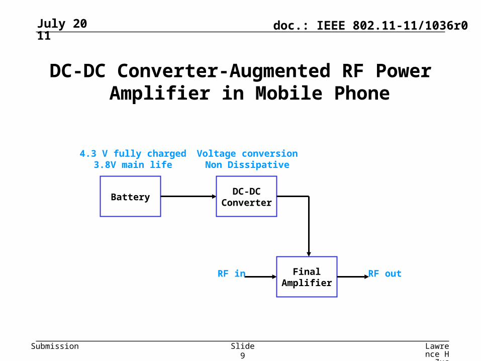
DC-DC Converter-Augmented RF Power Amplifier in Mobile Phone
Battery
4.3 V fully charged3.8V main life
DC-DCConverter
FinalAmplifier
RF in RF out
Voltage conversionNon Dissipative

July 2011
Lawrence H. Zuckerman, National Semiconductor Corp.
Slide 10
doc.: IEEE 802.11-11/1036r0
Submission
3.8V Battery Current Reduction w/DC-DCConverter on RF PA, 802.11g, 54 Mb/S OFDM
Without DC-DC Assist With DC-DC AssistRF Out Save Ibatt EVM RF Gain Ibatt EVM RF Gain Vsupl
dBm % Amp % dB Amp % dB Volts
20.0 34.5 0.322 1.33 30.5 0.211 2.50 30.5 2.5218.0 44.9 0.296 1.32 30.7 0.163 2.47 30.3 2.1716.0 52.5 0.278 1.34 30.7 0.132 2.44 30.1 1.9114.0 56.4 0.264 1.25 30.8 0.115 2.38 29.9 1.7712.0 59.6 0.255 1.07 30.8 0.103 2.41 29.4 1.6910.0 64.3 0.249 0.82 30.9 0.089 2.49 28.9 1.558.0 69.4 0.245 0.68 30.9 0.075 2.45 27.9 1.556.0 69.8 0.242 0.47 31.0 0.073 1.67 28.0 1.554.0 70.5 0.241 0.41 31.0 0.071 1.15 28.0 1.552.0 70.4 0.240 0.41 31.0 0.071 0.74 28.0 1.550.0 70.3 0.239 0.45 31.0 0.071 0.45 28.0 1.55

July 2011
Lawrence H. Zuckerman, National Semiconductor Corp.
Slide 11
doc.: IEEE 802.11-11/1036r0
Submission
Battery Current vs. RF Output PowerRF Power Amplifier, 802.11g, 54Mb/s, Vbatt=3.8V
0.000
0.050
0.100
0.150
0.200
0.250
0.300
0.350
0.0 5.0 10.0 15.0 20.0 25.0
RF Output, dBm
I b
at,
Am
ps
Without DC-DC Assist With DC-DC Assist
3.8V Battery Current Reduction w/DC-DCConverter on RF PA, 802.11g, 54 Mb/S OFDM

July 2011
Lawrence H. Zuckerman, National Semiconductor Corp.
Slide 12
doc.: IEEE 802.11-11/1036r0
Submission
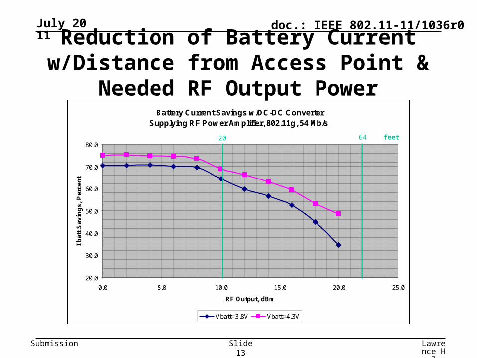
Reduction of Battery Current w/Distance from Access Point & Needed RF Output Power
• Even at power output of +22 dBm, needed for 802.11g at 64 feet from Access Point, application of DC-DC converter reduces Ibatt by 120 mA, 444 mW (44%)
• For reduction of power output to +10 dBm, allowable if 20 feet from Access Point, PA itself can reduce Ibatt from 151.2 mA to 40.7 mA by going into medium power mode
• Using DC-DC Converter, there is an additional reduction of 22.8 mA, 84.4 mW (44%).
• A WiFi PA device not configured to use a DC-DC converter draws 225 mA while delivering +22 dBm (the maximum it can deliver while meeting all 802.11 standards) and 95 mA while delivering +10 dBm
July 2011
Lawrence H. Zuckerman, National Semiconductor Corp.
Slide 13
doc.: IEEE 802.11-11/1036r0
Submission
Battery Current Savings w/DC-DC ConverterSupplying RF Power Amplifier, 802.11g, 54 Mb/s
20.0
30.0
40.0
50.0
60.0
70.0
80.0
0.0 5.0 10.0 15.0 20.0 25.0
RF Output, dBm
I b
att
Sav
ing
s, P
erce
nt
Vbatt=3.8V Vbatt=4.3V
Reduction of Battery Current w/Distance from Access Point & Needed RF Output Power
6420 feet

July 2011
Lawrence H. Zuckerman, National Semiconductor Corp.
Slide 14
doc.: IEEE 802.11-11/1036r0
Submission
Former address redacted

July 2011
Lawrence H. Zuckerman, National Semiconductor Corp.
Slide 15
doc.: IEEE 802.11-11/1036r0
Submission
• Careful set of definitions of terms used
• Comments on existing CCA recommendations
• The proposed elaborate CCA Method
• Estimation of network efficiency improvement
• Implementation details and issues
Summary of Advanced CCA Method in 94/132
Further Topics in Submission

July 2011
Lawrence H. Zuckerman, National Semiconductor Corp.
Slide 16
doc.: IEEE 802.11-11/1036r0
Submission
Fundamental Problem of Clear Channel Assessment as it is now done
The fundamental problem of present CCA is that the Subject Node can be cognizant of the interference conditions only at his location, yet an accurate CCA can be performed only if one knows the conditions at his Recipient’s location, the Incumbant’s location, and the location of Incumbant’s Recipient.
New Term Coined: TDA instead of CCAIt is useful to define a new term. In radio work on uncontrolled
bands there is, in general, no clear channel; so Clear-Channel Assessment is really a misnomer. The new process uses a complicated formula to determine whether or not to defer. Therefore, the new name for this process is TRANSMISSION DEFERRAL ASSESSMENT or “TDA”.

July 2011
Lawrence H. Zuckerman, National Semiconductor Corp.
Slide 17
doc.: IEEE 802.11-11/1036r0
Submission
Basic TDA Idea (1)
First, it is necessary to display Effective Radiated Power (“ERP”) in every Fragment preamble, with a resolution of 1 dB. If the overall range is from 1 mW up to 1.6 W, only 5 bits are required. Variable transmit ERP on a per-packet basis would provide additional throughput improvement. 3 dB steps would be ideal, but any ERP variation would be helpful. By keeping (initiating and updating) a (“Chart”) of transmitted and received ERP for every readable Node, each Node would have rough distance data (i.e. could draw concentric circles representing the distances). More precisely and importantly, each Node would “know” the path loss between himself and every other Node.

July 2011
Lawrence H. Zuckerman, National Semiconductor Corp.
Slide 18
doc.: IEEE 802.11-11/1036r0
Submission
Basic TDA Idea (2)
Secondly, in some prescribed manner, each Node periodically transmits its Chart; so that every Node ends up with all the Charts. The system determining when a Node includes his Chart (or even on occasion another Node’s Chart, to eliminate the Hidden Node effect) as a field, is governed by many factors, such as network loading and perceived changes to his Chart. During periods of light loading, the Charts can be broadcast via special network maintenance Transmissions; so they are ready for efficient operation when payload Packets/Fragments are ready.

July 2011
Lawrence H. Zuckerman, National Semiconductor Corp.
Slide 19
doc.: IEEE 802.11-11/1036r0
Submission
• The Subject Node does not need to draw a map; it has the exact information it needs to perform TDA:
• Incumbent Node’s ID, ERP, and Recipient’s ID, from Incumbent Node’s preamble;
• Path loss between the Incumbent Node and Recipient;
• Path loss between himself and his own Recipient;
• Path loss between himself and the Incumbent Node’s Recipient;
• Path loss between the Incumbent Node and Subject’s Recipient.
• All Subject has to do to begin a Transmission is calculate the lowest ERP which makes him 15 dB or more stronger than the Incumbent Node at his own Recipient’s location (and strong enough to be decoded by Same) and 15 dB or more weaker than the Occupying Node at the latter’s Recipient. If no such ERP is available to Subject, he Defers!
• The method works equally well for 3-dimensional geometry.
Basic TDA Idea (3)

July 2011
Lawrence H. Zuckerman, National Semiconductor Corp.
Slide 20
doc.: IEEE 802.11-11/1036r0
Submission
The method will increase network throughput, because it will decrease the probabilities of both False Deferrals and Ruined Transmissions. Owing to the available information, there is a greater probability of finding a high enough ERP; as every Transmission, including the ones initiated with no Activity, can be made using minimal ERP.

July 2011
Lawrence H. Zuckerman, National Semiconductor Corp.
Slide 21
doc.: IEEE 802.11-11/1036r0
Submission

July 2011
Lawrence H. Zuckerman, National Semiconductor Corp.
Slide 22
doc.: IEEE 802.11-11/1036r0
Submission

July 2011
Lawrence H. Zuckerman, National Semiconductor Corp.
Slide 23
doc.: IEEE 802.11-11/1036r0
Submission
Fortunate Results of this CCA (“TDA”) Method
• Hidden transmitter effects are mitigated
• For many occasions, a transmission can be made without interference, even while another transmission is in progress.
• Method works best with Transmit Power Control

July 2011
Lawrence H. Zuckerman, National Semiconductor Corp.
Slide 24
doc.: IEEE 802.11-11/1036r0
Submission
Further Work Needed/Requested
• Study and critique Submission P802.11-94/132 & 132R1
• Update the calculations to account for present-day modulation and symbol rates.
• Complete and update the “Estimation of Network Efficiency Improvement” that starts on Page 8 and goes to Page 15.
• Invent additional/complementary ways to use intelligent computing power to make the access points and stations work together to regulate transmitter output power and increase network throughput.

July 2011
Lawrence H. Zuckerman, National Semiconductor Corp.
Slide 25
doc.: IEEE 802.11-11/1036r0
Submission
References
• Zuckerman; IEEE 802.11-94/132 & /132r1
• Backes, Kwak, Durand, Qi, Ashley 802.11-07/0695