Embed Size (px)
Citation preview

Page 1 of 42 K0473 Issue 5
DO NOT PRINT THIS PAGE
Pressure measurement for research & industry
Druck Limited Fir Tree Lane
Groby Leicester LE6 0FH
England Tel: 0116 231 7100
Trench Etched
Resonant Pressure Sensor
TERPS 8000 Series
User Manual
K0473
Druck Limited 2013 This document is the property of Druck Limited and may not, either in part or whole, be copied or otherwise reproduced, communicated in any way to third parties, nor stored in any data processing system, without the express written authority of Druck Limited.
Page 2 of 42 K0473 Issue 5
DO NOT PRINT THIS PAGE
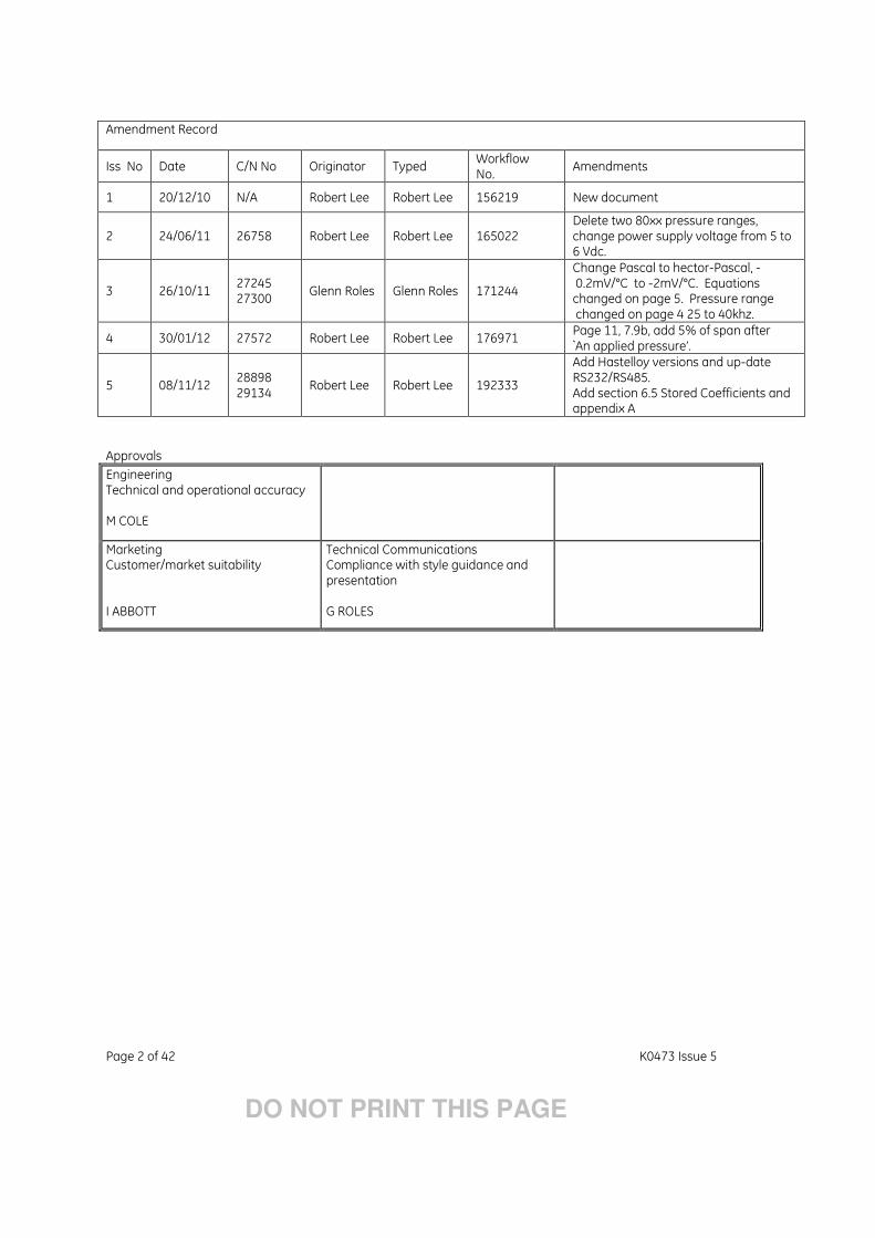
Amendment Record
Iss No Date C/N No Originator Typed Workflow No.
Amendments
1 20/12/10 N/A Robert Lee Robert Lee 156219 New document
2 24/06/11 26758 Robert Lee Robert Lee 165022 Delete two 80xx pressure ranges, change power supply voltage from 5 to 6 Vdc.
3 26/10/11 27245 27300
Glenn Roles Glenn Roles 171244
Change Pascal to hector-Pascal, - 0.2mV/°C to -2mV/°C. Equations changed on page 5. Pressure range changed on page 4 25 to 40khz.
4 30/01/12 27572 Robert Lee Robert Lee 176971 Page 11, 7.9b, add 5% of span after `An applied pressure’.
5 08/11/12 28898 29134
Robert Lee Robert Lee 192333
Add Hastelloy versions and up-date RS232/RS485. Add section 6.5 Stored Coefficients and appendix A
Approvals
Engineering Technical and operational accuracy M COLE
Marketing Customer/market suitability I ABBOTT
Technical Communications Compliance with style guidance and presentation G ROLES

Page 3 of 42 K0473 Issue 5
DO NOT PRINT THIS PAGE
Print Instructions • Finished Size: A5 • Print in colour on white throughout (covers + text), saddle stitched. • Cover to 285 gsm, content to 100 gsm. Translate into French, German, Italian, Spanish, Portuguese Brazilian, Simplified Chinese and Russian. THIS HARDCOPY IS NOT TO BE USED AS CAMERA COPY.

Page 4 of 42 K0473 Issue 5
DO NOT PRINT THIS PAGE
GEMeasurement & Control
Trench Etched Resonant Pressure Sensor
8000 Series User Manual - K0473

© 2013 General Electric Company. All rights reserved.

Safety • The manufacturer has designed this sensor to be safe when operated using the procedures detailed in this manual. Do not use this sensor for any other purpose than that stated.
• This publication contains operating and safety instructions that must be followed for safe operation and to maintain the sensor in a safe condition. The safety instructions are either warnings or cautions issued to protect the user and the equipment from injury or damage.
• Use qualified* personnel and good engineering practice for all procedures in this publication.
Pressure WARNING:Do not apply pressure greater the maximum safe working pressure to the sensor.
Toxic Materials There are no known toxic materials used in this sensor.
Maintenance The sensor must be maintained using the manufacturer’s procedures and these should be carried out by authorised service agents or the manufacturer’s service departments.
Technical Advice For technical advice contact the manufacturer.
* A qualified technician must have the necessary technical knowledge, documentation, special test equipment and tools to carry out the required work on this equipment.
EC Directives This equipment complies with:
BS EN 61000-6-1:2007BS EN 61000-6-2:2005BS EN 61000-6-3:2007BS EN 61000-6-4:2007BS EN 61326-1:2006
This equipment complies with the requirement of the Pressure Equipment Directive 97/23/EEC.
For further details see the Sales Data Sheet.A full conformity certificate is available from the manufacturer.
Contact GE Measurement & Control:www.ge-mcs.com
i K0473 Issue 5 - [EN] English
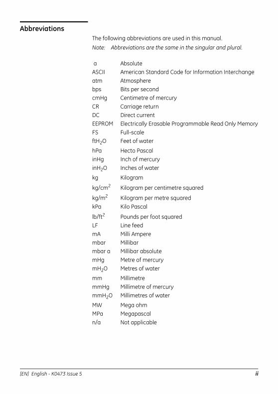
AbbreviationsThe following abbreviations are used in this manual.
Note: Abbreviations are the same in the singular and plural.
a AbsoluteASCII American Standard Code for Information Interchangeatm Atmospherebps Bits per secondcmHg Centimetre of mercuryCR Carriage returnDC Direct currentEEPROM Electrically Erasable Programmable Read Only MemoryFS Full-scaleftH2O Feet of water
hPa Hecto PascalinHg Inch of mercuryinH2O Inches of water
kg Kilogram
kg/cm2 Kilogram per centimetre squared
kg/m2 Kilogram per metre squaredkPa Kilo Pascal
lb/ft2 Pounds per foot squaredLF Line feedmA Milli Amperembar Millibarmbar a Millibar absolutemHg Metre of mercurymH2O Metres of water
mm MillimetremmHg Millimetre of mercurymmH2O Millimetres of water
MW Mega ohmMPa Megapascaln/a Not applicable
[EN] English - K0473 Issue 5 ii
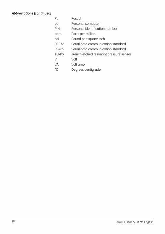
Abbreviations (continued)Pa Pascalpc Personal computerPIN Personal identification numberppm Parts per millionpsi Pound per square inchRS232 Serial data communication standardRS485 Serial data communication standardTERPS Trench etched resonant pressure sensorV VoltVA Volt amp°C Degrees centigrade
iii K0473 Issue 5 - [EN] English

[EN] English - K0473 Issue 5 iv
1 Introduction
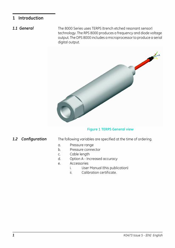
1.1 General The 8000 Series uses TERPS (trench etched resonant sensor) technology. The RPS 8000 produces a frequency and diode voltage output. The DPS 8000 includes a microprocessor to produce a serial digital output.
Figure 1 TERPS General view
1.2 Configuration The following variables are specified at the time of ordering.
a. Pressure rangeb. Pressure connectorc. Cable lengthd. Option A - Increased accuracye. Accessories
i. User Manual (this publication)ii. Calibration certificate.
1 K0473 Issue 5 - [EN] English
2 Installation TERPS 8XXX is a harsh media isolated product. Isolation is achieved by hermetically sealing the sensor chip in an oil filled chamber. The weight of this oil gives a g-sensitivity as a pressure offset error.
To calibrate the TERPS 8XXX, the unit is mounted vertically with the pressure port at the lowest point. Orientation other than this produces a pressure offset error as specified in the datasheet. The error is most noticeable at lower pressure ranges.Note: The g-sensitivity will also create an error in a high vibration
environment and the unit should be mounted accordingly.
TERPS 81XX is not a harsh media isolated product. There is negligible change in offset due to mounting position and vibration. Because the pressure media comes directly into contact with the sensor chip, care must be taken to ensure the pressure media does not damage the sensing chip.
2.1 Connecting TERPS to pressure source
When mounting the sensor, seal the mating surfaces. Failure to properly seal may affect performance or calibration accuracy.
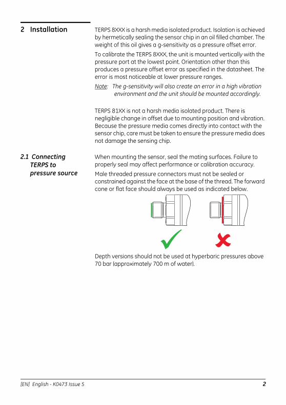
Male threaded pressure connectors must not be sealed or constrained against the face at the base of the thread. The forward cone or flat face should always be used as indicated below.
Depth versions should not be used at hyperbaric pressures above 70 bar (approximately 700 m of water).
[EN] English - K0473 Issue 5 2
3 TERPS media compatibility
3.1 TERPS 81XX 0 to 3.5 bar: non-condensing dry gases compatible with silicon, silicon dioxide, RTV adhesive, stainless steel 316L and glass.
3.2 TERPS 80XX- Ranges 0 to 200 bar: Fluids compatible with Stainless Steel 316L and Hastelloy C276.
Ranges 201 to 350 bar: Liquids and group II gases compatible with Stainless Steel 316L and Hastelloy C276.Fluid classification complies with EC directive 67/548/EEC. Statements comply with Pressure Equipment Directive 97/23/EC.
3.3 TERPS 82XX- Ranges 0 to 200 bar: Fluids compatible with Hastelloy C276.
Ranges 201 to 350 bar: Liquids and group II gases compatible with Hastelloy C276.Fluid classification complies with EC directive 67/548/EEC. Statements comply with Pressure Equipment Directive 97/23/EC.
3.4 TERPS 83XX- Ranges 0 to 200 bar: Fluids compatible with Hastelloy C276.
Ranges 201 to 350 bar: Liquids and group II gases compatible with Hastelloy C276.
Fluid classification complies with EC directive 67/548/EEC. Statements comply with Pressure Equipment Directive 97/23/EC.
4 Pressure containment
4.1 TERPS 81XX Ranges 0 to 3.5bar 7 bar maximum.
4.2 TERPS 8XXX- Ranges up to 7 bar: 70 bar maximum.
Ranges >7 to 100 bar: 200 bar maximum.
3 K0473 Issue 5 - [EN] English
5 Applying power to TERPS
5.1 Frequency and diode versions:
The TERPS sensor should be connected to stable power supply between 6 and 28 VDC.
Low jitter version require a less than 10 mA during normal operation.
Low power versions require less than 3.5 mA during normal operation.During power-up the sensor draws more than current than above, it is recommended that the power supply can supply a short term peak of at least 20 mA.
5.2 RS485 and RS232 Versions
The TERPS sensor should be connected to a stable power supply between 11 and 28 VDC. Current drawn is a nominal 16 mA peaking at 32 mA.
6 Measuring TERPS
6.1 Frequency and diode version
The frequency and diode version of the TERPS sensor requires the user to measure a frequency and a voltage to calculate pressure. The TERPS sensor has a very high level of repeatability that needs to be matched by the measurement system.
6.2 Measuring the Frequency
The frequency of the TERPS die is output as a TTL square wave referenced to ground in the range of 25 to 40 kHz. The frequency of the square wave needs to be measured to a better than 6.5 digits (i.e. 30 KHz to better than 0.05 Hz) to allow the sensor to meet quoted specification.To make sure the calculated output is correct, the measurement device should be regularly calibrated refer to the manufacturer’s instructions against a traceable standard.
6.3 Measuring the Diode Voltage
The diode signal is referenced to ground. It is a nominal 0.5 V at room temperature, and changes with a nominal -2mV/°C. To achieve the quoted specification of the sensor this signal must be measured to better than 0.01mV.To make sure the calculated output is correct, the measurement device should be regularly calibrated refer to the manufacturer’s instructions against a traceable standard.Note: Best practice, when measuring a TERPS device, take both measurements together. Where this is not possible the measurements should be taken as closely together as possible. Control the environment in which the TERPS is situated so it is not subjected to sudden changes in temperature and pressure.
[EN] English - K0473 Issue 5 4
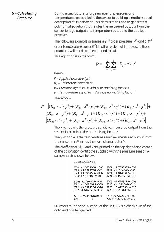
6.4 Calculating Pressure
During manufacture, a large number of pressures and temperatures are applied to the sensor to build-up a mathematical description of its behavior. This data is then used to generate a polynomial equation that relates the measured outputs from the sensor (bridge output and temperature output) to the applied pressure.
The following example assumes a 2nd order pressure (P2) and a 3rd order temperature signal (T3). If other orders of fit are used, these equations will need to be expanded to suit.
This equation is in the form:
Therefore:-
The x variable is the pressure sensitive, measured output from the sensor in Hz minus the normalising factor X.The y variable is the temperature sensitive, measured output from the sensor in mV minus the normalising factor Y.
The coefficients Kij, X and Y are printed on the top right-hand corner of the calibration certificate supplied with the pressure sensor. A sample set is shown below:
SN refers to the serial number of the unit, CS is a check sum of the data and can be ignored.
Where:
P = Applied pressure (psi)Ky = Calibration coefficientx = Pressure signal in Hz minus normalising factor Xy = Temperature signal in mV minus normalising factor Y
[ ][ ][ ])()()()(
)()()()(
)()()()(
3223
2222
1221
0220
3113
2112
1111
0110
3003
2002
1001
0000
yxKyxKyxKyxK
yxKyxKyxKyxK
yxKyxKyxKyxKP
⋅⋅+⋅⋅+⋅⋅+⋅⋅
+⋅⋅+⋅⋅+⋅⋅+⋅⋅
+⋅⋅+⋅⋅+⋅⋅+⋅⋅=
5 K0473 Issue 5 - [EN] English
6.5 Stored Coefficients
The coefficients are also stored internally on a serial EEPROM. See Appendix A for details on data format and communication information.
The internal EEPROM is only available on some electrical connector variants of the RPS 8000 series, see datasheet or calibration certificate for electrical connection details.
7 Using RS485 and RS232 versions
Output is compensated pressure in user specified units.
7.1 Serial Data Communications
RS485 bi-directional digital communication, no handshaking, user programmable baud rate between 300 and 9600 baud, 8 bit data, 1 stop bit. Format: ASCII text, pressure reading including pressure units. User programmable reading rate from one reading per second to one reading per 999999 seconds.
7.2 Applications The TERPS may be used as a single transducer directly connected to a serial interface. It can also be part of a network of devices using the programmed addressing facility. Each device on the network is a slave with a master device controlling the communications.The installed transducer is completely controlled by the serial interface. The TERPS transducer contains its characteristic data in an integral E2PROM.
7.3 RS485 Connections
Stand Alone RS485 Electrical connectionsRS485-B (or RS485 -)+ve supply 0V supplyRS485-A (or RS485 +)Transducer body (screen)Notes:
• Other connectors available refer to manufacturer.• For electrical connections refer to the sales data
sheet.
[EN] English - K0473 Issue 5 6
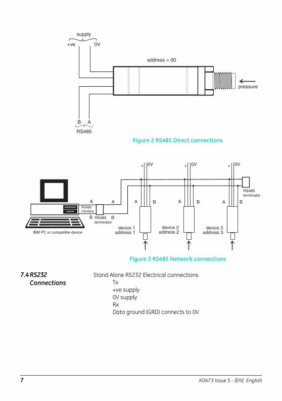
Figure 2 RS485 Direct connections
Figure 3 RS485 Network connections
7.4 RS232 Connections
Stand Alone RS232 Electrical connectionsTx+ve supply 0V supplyRxData ground (GRD) connects to 0V
7 K0473 Issue 5 - [EN] English
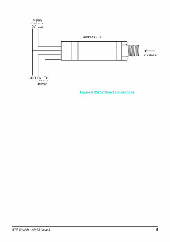
Figure 4 RS232 Direct connections
[EN] English - K0473 Issue 5 8
7.5 Command Summary
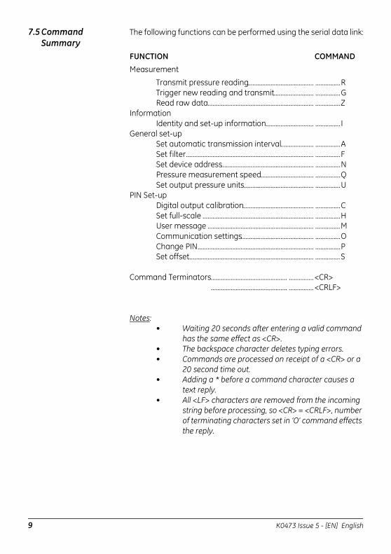
The following functions can be performed using the serial data link:
FUNCTION COMMANDMeasurement
Transmit pressure reading........................................ ...............RTrigger new reading and transmit........................ ...............GRead raw data................................................................ ...............Z
InformationIdentity and set-up information............................. ............... I
General set-upSet automatic transmission interval.................... ...............ASet filter............................................................................. ...............FSet device address........................................................ ...............NPressure measurement speed................................ ...............QSet output pressure units.......................................... ...............U
PIN Set-upDigital output calibration........................................... ...............CSet full-scale ................................................................... ...............HUser message ................................................................ ...............MCommunication settings............................................ ...............OChange PIN...................................................................... ...............PSet offset........................................................................... ...............S
Command Terminators.............................................. ...............<CR> .............................................. ...............<CRLF>
Notes:• Waiting 20 seconds after entering a valid command
has the same effect as <CR>. • The backspace character deletes typing errors.• Commands are processed on receipt of a <CR> or a
20 second time out.• Adding a * before a command character causes a
text reply.• All <LF> characters are removed from the incoming
string before processing, so <CR> = <CRLF>, number of terminating characters set in ‘O’ command effects the reply.
9 K0473 Issue 5 - [EN] English
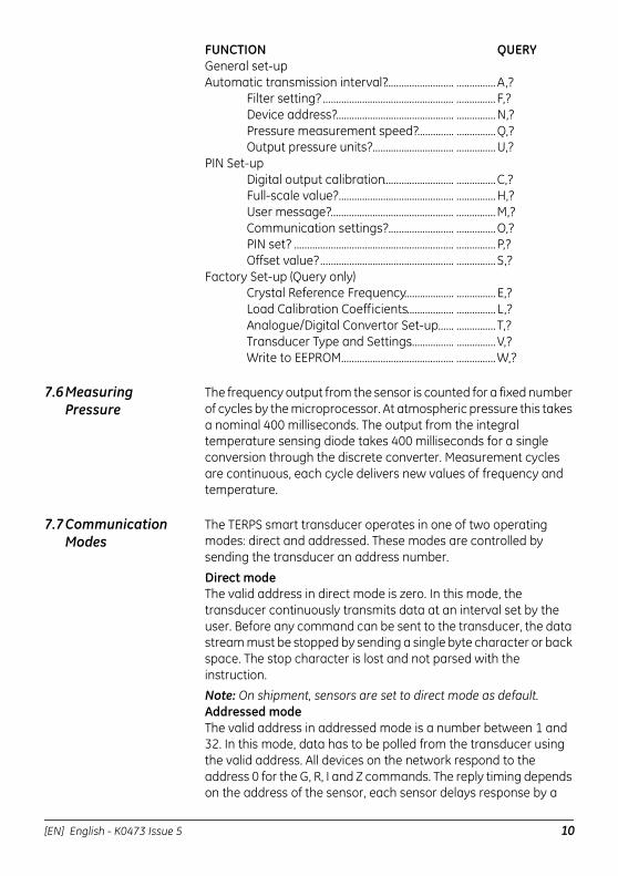
FUNCTION QUERYGeneral set-upAutomatic transmission interval?.......................... ...............A,?
Filter setting? .................................................. ............... F,?Device address?............................................. ...............N,?Pressure measurement speed?.............. ...............Q,?Output pressure units?............................... ...............U,?
PIN Set-upDigital output calibration........................... ...............C,?Full-scale value?............................................ ...............H,?User message?............................................... ...............M,?Communication settings?......................... ...............O,?PIN set? ............................................................. ...............P,?Offset value?................................................... ............... S,?
Factory Set-up (Query only)Crystal Reference Frequency................... ............... E,?Load Calibration Coefficients.................. ............... L,?Analogue/Digital Convertor Set-up...... ............... T,?Transducer Type and Settings................. ...............V,?Write to EEPROM........................................... ...............W,?
7.6 Measuring Pressure
The frequency output from the sensor is counted for a fixed number of cycles by the microprocessor. At atmospheric pressure this takes a nominal 400 milliseconds. The output from the integral temperature sensing diode takes 400 milliseconds for a single conversion through the discrete converter. Measurement cycles are continuous, each cycle delivers new values of frequency and temperature.
7.7 Communication Modes
The TERPS smart transducer operates in one of two operating modes: direct and addressed. These modes are controlled by sending the transducer an address number.
Direct modeThe valid address in direct mode is zero. In this mode, the transducer continuously transmits data at an interval set by the user. Before any command can be sent to the transducer, the data stream must be stopped by sending a single byte character or back space. The stop character is lost and not parsed with the instruction.Note: On shipment, sensors are set to direct mode as default.Addressed modeThe valid address in addressed mode is a number between 1 and 32. In this mode, data has to be polled from the transducer using the valid address. All devices on the network respond to the address 0 for the G, R, I and Z commands. The reply timing depends on the address of the sensor, each sensor delays response by a
[EN] English - K0473 Issue 5 10
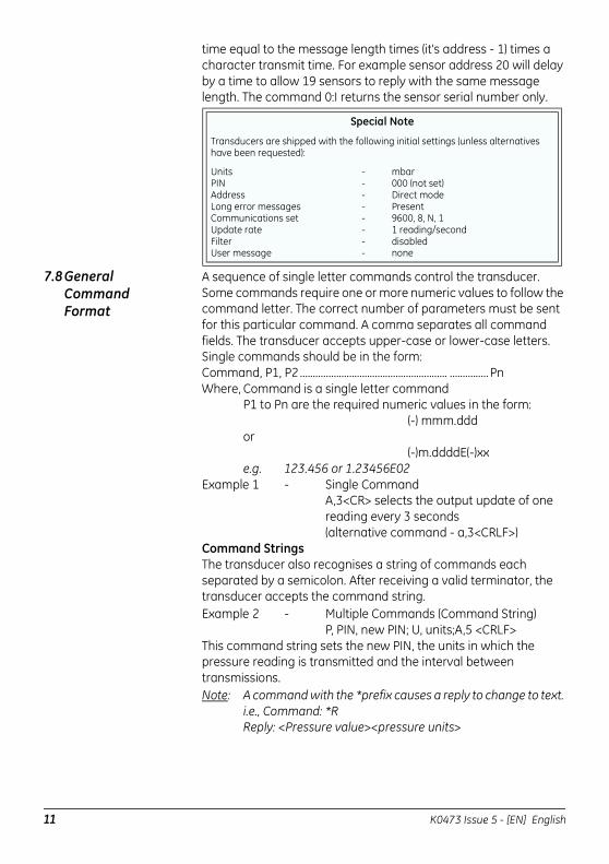
time equal to the message length times (it's address - 1) times a character transmit time. For example sensor address 20 will delay by a time to allow 19 sensors to reply with the same message length. The command 0:I returns the sensor serial number only.
7.8 General Command Format
A sequence of single letter commands control the transducer. Some commands require one or more numeric values to follow the command letter. The correct number of parameters must be sent for this particular command. A comma separates all command fields. The transducer accepts upper-case or lower-case letters.Single commands should be in the form:Command, P1, P2 ......................................................... ...............PnWhere, Command is a single letter command
P1 to Pn are the required numeric values in the form:(-) mmm.ddd
or(-)m.ddddE(-)xx
e.g. 123.456 or 1.23456E02Example 1 - Single Command
A,3<CR> selects the output update of onereading every 3 seconds(alternative command - a,3<CRLF>)
Command StringsThe transducer also recognises a string of commands each separated by a semicolon. After receiving a valid terminator, the transducer accepts the command string.Example 2 - Multiple Commands (Command String)
P, PIN, new PIN; U, units;A,5 <CRLF> This command string sets the new PIN, the units in which the pressure reading is transmitted and the interval between transmissions.Note: A command with the *prefix causes a reply to change to text.
i.e., Command: *R Reply: <Pressure value><pressure units>
Special Note
Transducers are shipped with the following initial settings (unless alternatives have been requested):
UnitsPINAddressLong error messagesCommunications setUpdate rateFilterUser message
--------
mbar000 (not set)Direct modePresent9600, 8, N, 11 reading/seconddisablednone
11 K0473 Issue 5 - [EN] English
Command String Limitations
A command string must not be more than thirty characters. The transducer ignores all the commands in a string containing more than thirty characters.
Network Mode SyntaxIn this mode an address field must be added to the start of the general format as follows:
Address: command,P1,P2.......................................... ...............Ppnwhere:‘Address’ is the address of the transducer to send the command
‘:’ is the end of the address field‘command’ is the single letter instruction‘P1’ to ‘Pn’ are the required numeric values
Example 3 - 1:R<CR>Get device @ address 1 to transmit pressure
7.9 Error Message Error messages are generated from two sources:a. User commands
In a command string, the transducer accepts correct commands and rejects incorrect commands. An incorrect command causes the transducer to send an error message related to the command.
Error Message FormatThe form of the error message:
ERROR nn - where nn is a decimal numberDefined error numbers are detailed in Table 1, page 28.
b. Transducer faultA transducer fault sends an error message blocking the transmission of pressure data and sending the fault message in place of data.Error messagesAn applied pressure, 5% of span out of the calibrated range, causes:
*Over Pressure**Under Pressure*
A damaged transducer or no frequency output from the transducer causes:
**** NO RPT ****
[EN] English - K0473 Issue 5 12
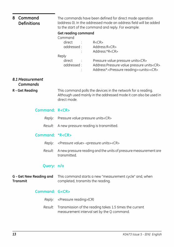
8 Command Definitions
The commands have been defined for direct mode operation (address 0). In the addressed mode an address field will be added to the start of the command and reply. For example:
Get reading commandCommand
direct : R<CR> addressed : Address:R<CR>
: Address:*R<CR>Reply
direct : Pressure value pressure units<CR>addressed : Address:Pressure value pressure units<CR>
: Address*:<Pressure reading><units><CR>
8.1 Measurement Commands
R - Get Reading This command polls the devices in the network for a reading. Although used mainly in the addressed mode it can also be used in direct mode.
Command: R<CR>
Reply: Pressure value pressure units<CR>
Result: A new pressure reading is transmitted.
Command: *R<CR>
Reply: <Pressure value> <pressure units><CR>
Result: A new pressure reading and the units of pressure measurement are transmitted.
Query: n/a
G - Get New Reading and Transmit
This command starts a new "measurement cycle" and, when completed, transmits the reading.
Command: G<CR>
Reply: <Pressure reading>(CR)
Result: Transmission of the reading takes 1.5 times the current measurement interval set by the Q command.
13 K0473 Issue 5 - [EN] English
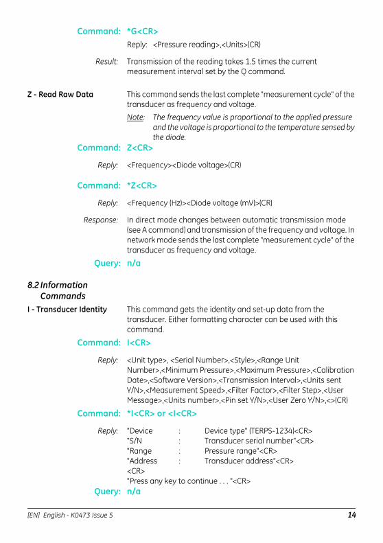
Command: *G<CR>Reply: <Pressure reading>,<Units>(CR)
Result: Transmission of the reading takes 1.5 times the current measurement interval set by the Q command.
Z - Read Raw Data This command sends the last complete "measurement cycle" of the transducer as frequency and voltage.
Note: The frequency value is proportional to the applied pressure and the voltage is proportional to the temperature sensed by the diode.
Command: Z<CR>
Reply: <Frequency><Diode voltage>(CR)
Command: *Z<CR>
Reply: <Frequency (Hz)><Diode voltage (mV)>(CR)
Response: In direct mode changes between automatic transmission mode (see A command) and transmission of the frequency and voltage. In network mode sends the last complete "measurement cycle" of the transducer as frequency and voltage.
Query: n/a
8.2 Information Commands
I - Transducer Identity This command gets the identity and set-up data from the transducer. Either formatting character can be used with this command.
Command: I<CR>
Reply: <Unit type>, <Serial Number>,<Style>,<Range Unit Number>,<Minimum Pressure>,<Maximum Pressure>,<Calibration Date>,<Software Version>,<Transmission Interval>,<Units sent Y/N>,<Measurement Speed>,<Filter Factor>,<Filter Step>,<User Message>,<Units number>,<Pin set Y/N>,<User Zero Y/N>,<>(CR)
Command: *I<CR> or <I<CR>
Reply: "Device : Device type" (TERPS-1234)<CR>"S/N : Transducer serial number"<CR>"Range : Pressure range"<CR>"Address : Transducer address"<CR><CR>"Press any key to continue . . . "<CR>
Query: n/a
[EN] English - K0473 Issue 5 14
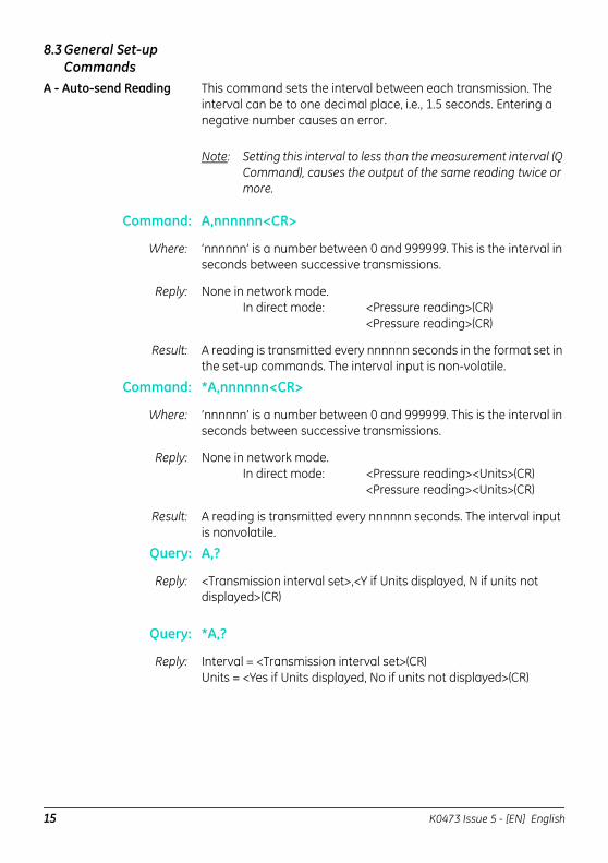
8.3 General Set-up Commands
A - Auto-send Reading This command sets the interval between each transmission. The interval can be to one decimal place, i.e., 1.5 seconds. Entering a negative number causes an error.
Note: Setting this interval to less than the measurement interval (Q Command), causes the output of the same reading twice or more.
Command: A,nnnnnn<CR>
Where: ‘nnnnnn’ is a number between 0 and 999999. This is the interval in seconds between successive transmissions.
Reply: None in network mode. In direct mode: <Pressure reading>(CR)
<Pressure reading>(CR)
Result: A reading is transmitted every nnnnnn seconds in the format set in the set-up commands. The interval input is non-volatile.
Command: *A,nnnnnn<CR>
Where: ‘nnnnnn’ is a number between 0 and 999999. This is the interval in seconds between successive transmissions.
Reply: None in network mode. In direct mode: <Pressure reading><Units>(CR)
<Pressure reading><Units>(CR)
Result: A reading is transmitted every nnnnnn seconds. The interval input is nonvolatile.
Query: A,?
Reply: <Transmission interval set>,<Y if Units displayed, N if units not displayed>(CR)
Query: *A,?
Reply: Interval = <Transmission interval set>(CR)Units = <Yes if Units displayed, No if units not displayed>(CR)
15 K0473 Issue 5 - [EN] English
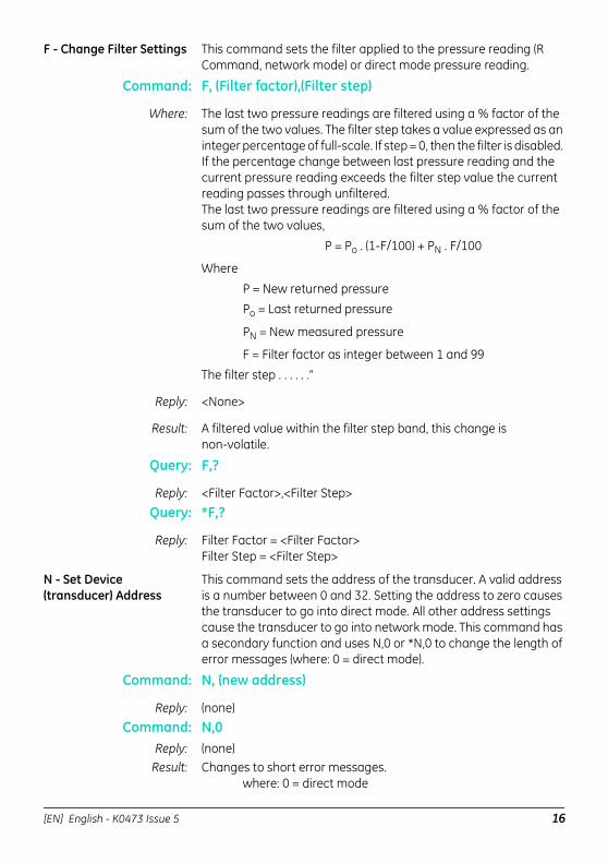
F - Change Filter Settings This command sets the filter applied to the pressure reading (R Command, network mode) or direct mode pressure reading.
Command: F, (Filter factor),(Filter step)
Where: The last two pressure readings are filtered using a % factor of the sum of the two values. The filter step takes a value expressed as an integer percentage of full-scale. If step = 0, then the filter is disabled. If the percentage change between last pressure reading and the current pressure reading exceeds the filter step value the current reading passes through unfiltered. The last two pressure readings are filtered using a % factor of the sum of the two values,
P = Po . (1-F/100) + PN . F/100
Where
P = New returned pressurePo = Last returned pressure
PN = New measured pressure
F = Filter factor as integer between 1 and 99
The filter step . . . . . .”
Reply: <None>
Result: A filtered value within the filter step band, this change is non-volatile.
Query: F,?
Reply: <Filter Factor>,<Filter Step>Query: *F,?
Reply: Filter Factor = <Filter Factor>Filter Step = <Filter Step>
N - Set Device (transducer) Address
This command sets the address of the transducer. A valid address is a number between 0 and 32. Setting the address to zero causes the transducer to go into direct mode. All other address settings cause the transducer to go into network mode. This command has a secondary function and uses N,0 or *N,0 to change the length of error messages (where: 0 = direct mode).
Command: N, (new address)
Reply: (none)Command: N,0
Reply: (none)Result: Changes to short error messages.
where: 0 = direct mode
[EN] English - K0473 Issue 5 16
Command: *N,0
Reply: (none)
Result: Changes to long error messages.where: 0 = direct mode
Example: Address 1 change to long error messages:1:*N,1Query: N,?
Reply: <Device Address> (CR)Query: *N,?
Reply: Device Address =<Device Address> (CR)
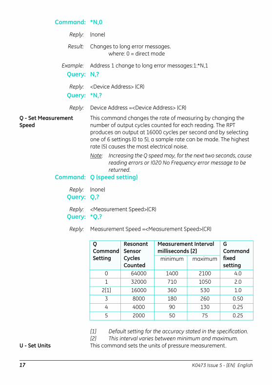
Q - Set Measurement Speed
This command changes the rate of measuring by changing the number of output cycles counted for each reading. The RPT produces an output at 16000 cycles per second and by selecting one of 6 settings (0 to 5), a sample rate can be made. The highest rate (5) causes the most electrical noise. Note: Increasing the Q speed may, for the next two seconds, cause
reading errors or !020 No Frequency error message to be returned.
Command: Q (speed setting)
Reply: (none)Query: Q,?
Reply: <Measurement Speed>(CR)Query: *Q,?
Reply: Measurement Speed =<Measurement Speed>(CR)
[1] Default setting for the accuracy stated in the specification.[2] This interval varies between minimum and maximum.
U - Set Units This command sets the units of pressure measurement.
QCommand Setting
Resonant Sensor Cycles Counted
Measurement Interval milliseconds [2]
G Command fixed setting
minimum maximum
0 64000 1400 2100 4.01 32000 710 1050 2.0
2[1] 16000 360 530 1.03 8000 180 260 0.504 4000 90 130 0.255 2000 50 75 0.25
17 K0473 Issue 5 - [EN] English
Either formatting character can be used with this command.
Command: U,nn<CR>
Where: ‘nn’ is a number between 0 and 24 used to select the required units.
Reply: <none>
Result: Changes the pressure units of the transmitted reading.
Query: U,?
Reply: <unit number> (CR)
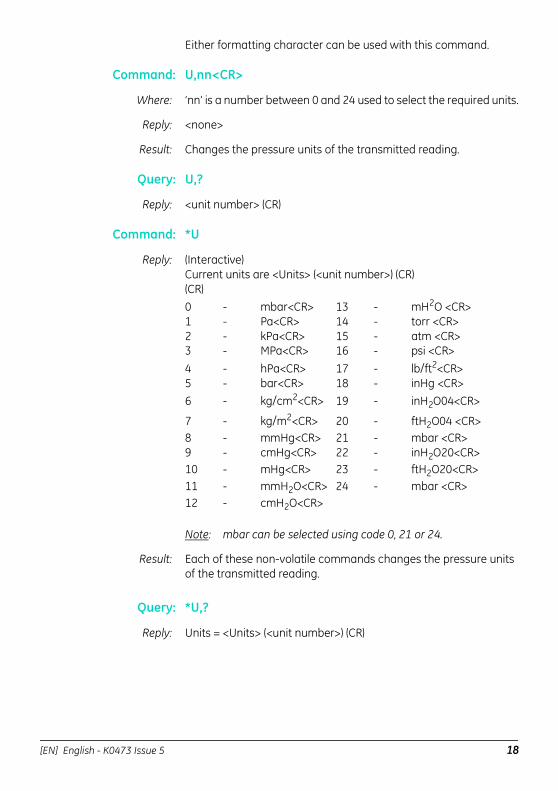
Command: *U
Reply: (Interactive)Current units are <Units> (<unit number>) (CR)(CR)0 - mbar<CR> 13 - mH2O <CR>1 - Pa<CR> 14 - torr <CR>2 - kPa<CR> 15 - atm <CR>3 - MPa<CR> 16 - psi <CR>4 - hPa<CR> 17 - lb/ft2<CR>5 - bar<CR> 18 - inHg <CR>6 - kg/cm2<CR> 19 - inH2O04<CR>
7 - kg/m2<CR> 20 - ftH2O04 <CR>8 - mmHg<CR> 21 - mbar <CR>9 - cmHg<CR> 22 - inH2O20<CR>10 - mHg<CR> 23 - ftH2O20<CR>11 - mmH2O<CR> 24 - mbar <CR>12 - cmH2O<CR>
Note: mbar can be selected using code 0, 21 or 24.
Result: Each of these non-volatile commands changes the pressure units of the transmitted reading.
Query: *U,?
Reply: Units = <Units> (<unit number>) (CR)
[EN] English - K0473 Issue 5 18
8.4 PIN Protected Set-up Commands
C - User Calibration This command allows the user to perform a two point calibration on the output of the device. The calibration routine requires two pressures to be applied within the operating extremes and in units of pressure measurement set in the transducer. The software calculates an offset and gain correction to all subsequent readings.
Command: C or *C
Reply: (Interactive)
Reply: Enter PIN’ => (enter PIN)
Reply: “Apply first pressure, then send <CR>” (when stable, send <CR>)
Reply: “Enter applied pressure (<units>)” =>(enter pressure value in specified units) <CR>
Reply: “Apply second pressure, then send <CR>” (when stable, send <CR>)
Reply: “Enter applied pressure (<units>)” =>(enter pressure value in specified units) <CR>
Reply: “Pressure gain = <new pressure gain>” (CR)“Pressure offset = <new pressure offset>” (CR)“Accept these values? (Y/N) =>(Enter Y or N)
(Y answered) “EEPROM updated” <CR>(N answered) “Current settings left unchanged” <CR>(If invalid data entered) “!023 Bad Cal Pres” <CR>
Command: *C,PIN,mode,?<CR> Non-interactive calibration requires the C command to be used twice, i.e. two calibration pressures must be entered for a straight line fit.
Proceed as follows:Command: *C,PIN,1,?<CR>
Where: ‘PIN‘ is the PIN of the transducer and ‘1‘ is the first pressure value. Apply pressure 1, when stable send:
C,(PIN),1,<CR> Note: Sending *C,PIN,1,?<CR> causes the current stored data for
pressure 1 to be sent.Apply pressure 2, when stable send:
C,(PIN),2,<CR>
19 K0473 Issue 5 - [EN] English
Query: C,PIN,mode?
Reply: <Measured>,<Applied><Got first point (Yes/No)> (CR)
Query: *C,?
Reply: “Measured Pressure = <Measured>” (CR)“Applied Pressure = <Applied>” (CR)“First Point Done=<Yes/No>(CR)
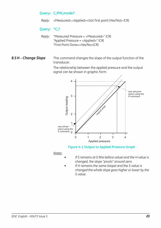
8.5 H - Change Slope This command changes the slope of the output function of the transducer.The relationship between the applied pressure and the output signal can be shown in graphic form:
Figure 4-1 Output to Applied Pressure Graph
Notes:• If S remains at 0 (the before value) and the H value is
changed, the slope "pivots" around zero.• If H remains the same (slope) and the S value is
changed the whole slope goes higher or lower by the S value.
orig
inal
slop
e
Outp
utre
adin
g
Applied pressure
0 1 2 3 4
0
1
2
3
4
new set-point(span) using theH command
new off-set(zero) using theS command
[EN] English - K0473 Issue 5 20
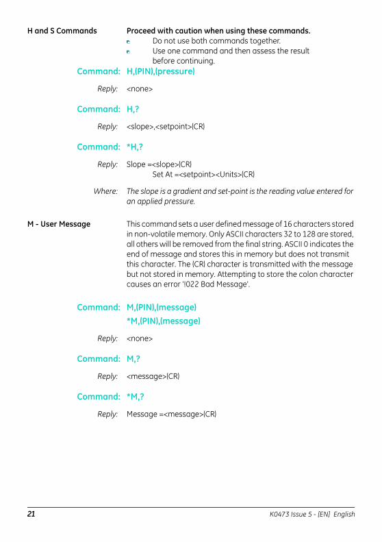
H and S Commands Proceed with caution when using these commands. Do not use both commands together. Use one command and then assess the result
before continuing.Command: H,(PIN),(pressure)
Reply: <none>
Command: H,?
Reply: <slope>,<setpoint>(CR)
Command: *H,?
Reply: Slope =<slope>(CR)Set At =<setpoint><Units>(CR)
Where: The slope is a gradient and set-point is the reading value entered for an applied pressure.
M - User Message This command sets a user defined message of 16 characters stored in non-volatile memory. Only ASCII characters 32 to 128 are stored, all others will be removed from the final string. ASCII 0 indicates the end of message and stores this in memory but does not transmit this character. The (CR) character is transmitted with the message but not stored in memory. Attempting to store the colon character causes an error '!022 Bad Message'.
Command: M,(PIN),(message)*M,(PIN),(message)
Reply: <none>
Command: M,?
Reply: <message>(CR)
Command: *M,?
Reply: Message =<message>(CR)
21 K0473 Issue 5 - [EN] English
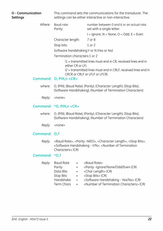
O - Communication Settings
This command sets the communications for the transducer. The settings can be either interactive or non-interactive.
Where: Baud rate: number between 0 and 6 or an actual rate.Parity: set with a single letter:
I = ignore, N = None, O = Odd, E = Even
Character length: 7 or 8
Stop bits: 1 or 2Software handshaking:Y or N (Yes or No)
Termination characters:1 or 2
(1 = transmitted lines must end in CR, received lines end in either CR or LF).(2 = transmitted lines must end in CRLF, received lines end in CRCR or CRLF or LFLF or LFCR).
Command: O, PIN,n <CR>
where: O, (PIN), (Baud Rate), (Parity), (Character Length), (Stop Bits), (Software Handshaking), (Number of Termination Characters)
Reply: <none>
Command: *O, PIN,n <CR>
where: O, (PIN), (Baud Rate), (Parity), (Character Length), (Stop Bits), (Software Handshaking), (Number of Termination Characters)
Reply: <none>
Command: O,?
Reply: <Baud Rate>, <Parity -NIEO>, <Character Length>, <Stop Bits>, <Software Handshaking - Y/N>, <Number of Termination Characters> (CR)
Command: *O,?
Reply: Baud Rate = <Baud Rate>Parity = <Parity -Ignore/None/Odd/Even (CR)Data Bits = <Char Length> (CR)Stop Bits = <Stop Bits> (CR)Handshake = <Software Handshaking - Yes/No> (CR)Term Chars = <Number of Termination Characters> (CR)
[EN] English - K0473 Issue 5 22
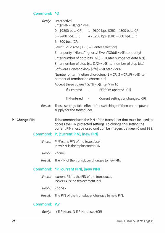
Command: *O
Reply: (Interactive)Enter PIN - >(Enter PIN)0 - 19200 bps. (CR) 1 - 9600 bps. (CR)2 - 4800 bps. (CR)
3 - 2400 bps. (CR) 4 - 1200 bps. (CR)5 - 600 bps. (CR)
6 - 300 bps. (CR)Select Baud rate (0 - 6) = >(enter selection)
Enter parity ([N]one/[I]gnore/[E]ven/[O]dd) = >(Enter parity)
Enter number of data bits (7/8) = >(Enter number of data bits)Enter number of stop bits (1/2) = >(Enter number of stop bits)
Software Handshaking? (Y/N) = >(Enter Y or N)
Number of termination characters (1 = CR, 2 = CRLF) = >(Enter number of termination characters)
Accept these values? (Y/N) = >(Enter Y or N)
If Y entered - EEPROM updated. (CR)
If N entered - Current settings unchanged. (CR)
Result: These settings take effect after switching off then on the power supply for the transducer.
P - Change PIN This command sets the PIN of the transducer that must be used to access the PIN protected settings. To change this setting the current PIN must be used and can be integers between 0 and 999.
Command: P, (current PIN), (new PIN)
Where: PIN’ is the PIN of the transducer.‘NewPIN’ is the replacement PIN.
Reply: <none>
Result: The PIN of the transducer changes to new PIN.
Command: *P, (current PIN), (new PIN)
Where: ‘current PIN’ is the PIN of the transducer. ‘new PIN’ is the replacement PIN.
Reply: <none>
Result: The PIN of the transducer changes to new PIN.
Command: P,?
Reply: (Y if PIN set, N if PIN not set) (CR)
23 K0473 Issue 5 - [EN] English
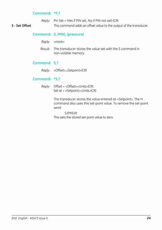
Command: *P,?
Reply: Pin Set = (Yes if PIN set, No if PIN not set) (CR)S - Set Offset This command adds an offset value to the output of the transducer.
Command: S, (PIN), (pressure)
Reply: <none>
Result: The transducer stores the value set with the S command in non-volatile memory.
Command: S,?
Reply: <Offset>,<Setpoint>(CR)
Command: *S,?
Reply: Offset = <Offset><Units>(CR)Set at = <Setpoint><Units>(CR)
The transducer stores the value entered as <Setpoint>. The H command also uses this set-point value. To remove the set-point send:
S,(PIN),(X)This sets the stored set-point value to zero.
[EN] English - K0473 Issue 5 24
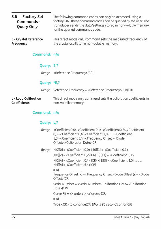
8.6 Factory Set Commands - Query Only
The following command codes can only be accessed using a factory PIN. These command codes can be queried by the user. The transducer sends the data/settings stored in non-volatile memory for the queried commands code.
E - Crystal Reference Frequency
This direct mode only command sets the measured frequency of the crystal oscillator in non-volatile memory.
Command: n/a
Query: E,?
Reply: <Reference Frequency>(CR)
Query: *E,?
Reply: Reference Frequency = <Reference Frequency>kHz(CR)
L - Load Calibration Coefficients
This direct mode only command sets the calibration coefficients in non-volatile memory.
Command: n/a
Query: L,?
Reply: <Coefficient0,0>,<Coefficient 0,1>,<Coefficient0,2>,<Coefficient 0,3>,<Coefficient 0,4>,<Coefficient 1,0>, ... ,<Coefficient 5,3>,<Coefficient 5,4>,<Frequency Offset>,<Diode Offset>,<Calibration Date>(CR)
Reply: K[0][0] = <Coefficient 0,0> K[0][1] = <Coefficient 0,1> K[0][2] = <Coefficient 0,2>(CR) K[0][3] = <Coefficient 0,3>
K[0][4] = <Coefficient 0,4> (CR) K[1][0] = <Coefficient 1,0> ...... ... K[5][4] = <Coefficient 5,4>(CR)(CR) Frequency Offset (X) = <Frequency Offset> Diode Offset (Y)= <Diode Offset>(CR)Serial Number = <Serial Number> Calibration Date= <Calibration Date>(CR)
Curve Fit = <X order> x <Y order>(CR)(CR)
Type <CR> to continue(CR) (Waits 20 seconds or for CR)
25 K0473 Issue 5 - [EN] English
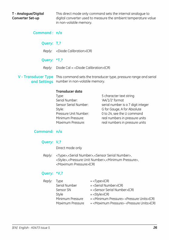
T - Analogue/Digital Converter Set-up
This direct mode only command sets the internal analogue to digital converter used to measure the ambient temperature value in non-volatile memory.
Command : n/a
Query: T,?
Reply: <Diode Calibration>(CR)
Query: *T,?
Reply: Diode Cal = <Diode Calibration>(CR)
V - Transducer Typeand Settings
This command sets the transducer type, pressure range and serial number in non-volatile memory.
Transducer dataType: 5 character text stringSerial Number: ‘AA/1/2’ formatSensor Serial Number: serial number is a 7 digit integerStyle: G for Gauge, A for AbsolutePressure Unit Number: 0 to 24, see the U commandMinimum Pressure: real numbers in pressure unitsMaximum Pressure: real numbers in pressure units
Command: n/a
Query: V,?Direct mode only
Reply: <Type>,<Serial Number>,<Sensor Serial Number>,<Style>,<Pressure Unit Number>,<Minimum Pressure>,<Maximum Pressure>(CR)
Query: *V,?
Reply: Type = <Type>(CR)Serial Number = <Serial Number>(CR)Sensor SN = <Sensor Serial Number>(CR)Style = <Style>(CR)Minimum Pressure = <Minimum Pressure> <Pressure Units>(CR)Maximum Pressure = <Maximum Pressure> <Pressure Units>(CR)
[EN] English - K0473 Issue 5 26
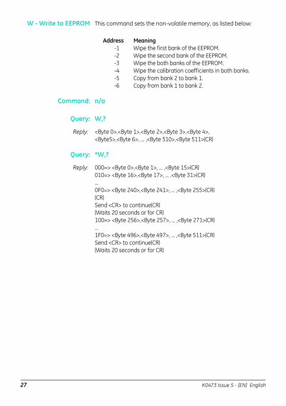
W - Write to EEPROM This command sets the non-volatile memory, as listed below:
Address Meaning-1 Wipe the first bank of the EEPROM.-2 Wipe the second bank of the EEPROM.-3 Wipe the both banks of the EEPROM.-4 Wipe the calibration coefficients in both banks.-5 Copy from bank 2 to bank 1.-6 Copy from bank 1 to bank 2.
Command: n/a
Query: W,?
Reply: <Byte 0>,<Byte 1>,<Byte 2>,<Byte 3>,<Byte 4>,<Byte5>,<Byte 6>, ... ,<Byte 510>,<Byte 511>(CR)
Query: *W,?
Reply: 000=> <Byte 0>,<Byte 1>, ... ,<Byte 15>(CR)010=> <Byte 16>,<Byte 17>, ... ,<Byte 31>(CR)...0F0=> <Byte 240>,<Byte 241>, ... ,<Byte 255>(CR)(CR)Send <CR> to continue(CR)(Waits 20 seconds or for CR)100=> <Byte 256>,<Byte 257>, ... ,<Byte 271>(CR)...1F0=> <Byte 496>,<Byte 497>, ... ,<Byte 511>(CR)Send <CR> to continue(CR)(Waits 20 seconds or for CR)
27 K0473 Issue 5 - [EN] English
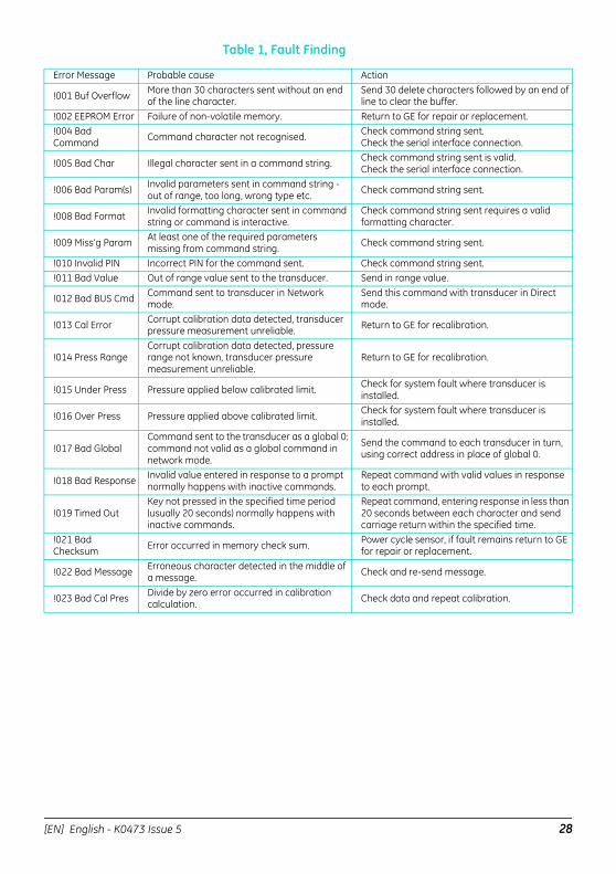
Table 1, Fault Finding
Error Message Probable cause Action
!001 Buf Overflow More than 30 characters sent without an end of the line character.
Send 30 delete characters followed by an end of line to clear the buffer.
!002 EEPROM Error Failure of non-volatile memory. Return to GE for repair or replacement.!004 Bad Command Command character not recognised. Check command string sent.
Check the serial interface connection.
!005 Bad Char Illegal character sent in a command string. Check command string sent is valid. Check the serial interface connection.
!006 Bad Param(s) Invalid parameters sent in command string - out of range, too long, wrong type etc. Check command string sent.
!008 Bad Format Invalid formatting character sent in command string or command is interactive.
Check command string sent requires a valid formatting character.
!009 Miss’g Param At least one of the required parameters missing from command string. Check command string sent.
!010 Invalid PIN Incorrect PIN for the command sent. Check command string sent.!011 Bad Value Out of range value sent to the transducer. Send in range value.
!012 Bad BUS Cmd Command sent to transducer in Network mode.
Send this command with transducer in Direct mode.
!013 Cal Error Corrupt calibration data detected, transducer pressure measurement unreliable. Return to GE for recalibration.
!014 Press RangeCorrupt calibration data detected, pressure range not known, transducer pressure measurement unreliable.
Return to GE for recalibration.
!015 Under Press Pressure applied below calibrated limit. Check for system fault where transducer is installed.
!016 Over Press Pressure applied above calibrated limit. Check for system fault where transducer is installed.
!017 Bad GlobalCommand sent to the transducer as a global 0: command not valid as a global command in network mode.
Send the command to each transducer in turn, using correct address in place of global 0.
!018 Bad Response Invalid value entered in response to a prompt normally happens with inactive commands.
Repeat command with valid values in response to each prompt.
!019 Timed OutKey not pressed in the specified time period (usually 20 seconds) normally happens with inactive commands.
Repeat command, entering response in less than 20 seconds between each character and send carriage return within the specified time.
!021 Bad Checksum Error occurred in memory check sum. Power cycle sensor, if fault remains return to GE
for repair or replacement.
!022 Bad Message Erroneous character detected in the middle of a message. Check and re-send message.
!023 Bad Cal Pres Divide by zero error occurred in calibration calculation. Check data and repeat calibration.
[EN] English - K0473 Issue 5 28
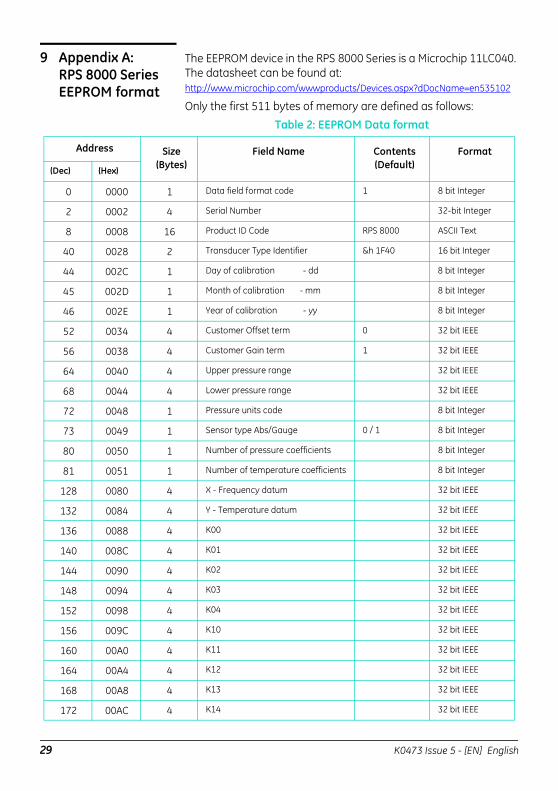
9 Appendix A: RPS 8000 Series EEPROM format
The EEPROM device in the RPS 8000 Series is a Microchip 11LC040. The datasheet can be found at: http://www.microchip.com/wwwproducts/Devices.aspx?dDocName=en535102
Only the first 511 bytes of memory are defined as follows:Table 2: EEPROM Data format
Address Size(Bytes)
Field Name
Contents(Default)
Format (Dec) (Hex)
0 0000 1 Data field format code 1 8 bit Integer
2 0002 4 Serial Number 32-bit Integer
8 0008 16 Product ID Code RPS 8000 ASCII Text
40 0028 2 Transducer Type Identifier &h 1F40 16 bit Integer
44 002C 1 Day of calibration - dd 8 bit Integer
45 002D 1 Month of calibration - mm 8 bit Integer
46 002E 1 Year of calibration - yy 8 bit Integer
52 0034 4 Customer Offset term 0 32 bit IEEE
56 0038 4 Customer Gain term 1 32 bit IEEE
64 0040 4 Upper pressure range 32 bit IEEE
68 0044 4 Lower pressure range 32 bit IEEE
72 0048 1 Pressure units code 8 bit Integer
73 0049 1 Sensor type Abs/Gauge 0 / 1 8 bit Integer
80 0050 1 Number of pressure coefficients 8 bit Integer
81 0051 1 Number of temperature coefficients 8 bit Integer
128 0080 4 X - Frequency datum 32 bit IEEE
132 0084 4 Y - Temperature datum 32 bit IEEE
136 0088 4 K00 32 bit IEEE
140 008C 4 K01 32 bit IEEE
144 0090 4 K02 32 bit IEEE
148 0094 4 K03 32 bit IEEE
152 0098 4 K04 32 bit IEEE
156 009C 4 K10 32 bit IEEE
160 00A0 4 K11 32 bit IEEE
164 00A4 4 K12 32 bit IEEE
168 00A8 4 K13 32 bit IEEE
172 00AC 4 K14 32 bit IEEE
29 K0473 Issue 5 - [EN] English
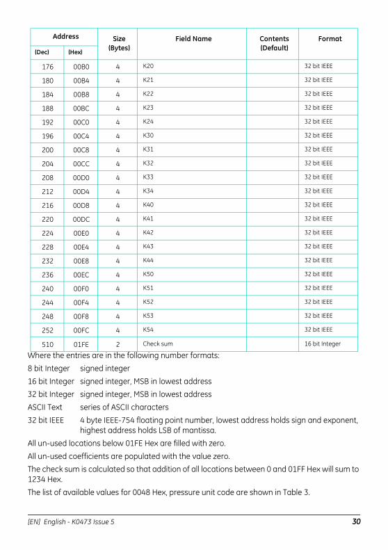
Where the entries are in the following number formats:
8 bit Integer signed integer
16 bit Integer signed integer, MSB in lowest address32 bit Integer signed integer, MSB in lowest address
ASCII Text series of ASCII characters
32 bit IEEE 4 byte IEEE-754 floating point number, lowest address holds sign and exponent, highest address holds LSB of mantissa.
All un-used locations below 01FE Hex are filled with zero.
All un-used coefficients are populated with the value zero.The check sum is calculated so that addition of all locations between 0 and 01FF Hex will sum to 1234 Hex.
The list of available values for 0048 Hex, pressure unit code are shown in Table 3.
Address Size(Bytes)
Field Name
Contents(Default)
Format (Dec) (Hex)
176 00B0 4 K20 32 bit IEEE
180 00B4 4 K21 32 bit IEEE
184 00B8 4 K22 32 bit IEEE
188 00BC 4 K23 32 bit IEEE
192 00C0 4 K24 32 bit IEEE
196 00C4 4 K30 32 bit IEEE
200 00C8 4 K31 32 bit IEEE
204 00CC 4 K32 32 bit IEEE
208 00D0 4 K33 32 bit IEEE
212 00D4 4 K34 32 bit IEEE
216 00D8 4 K40 32 bit IEEE
220 00DC 4 K41 32 bit IEEE
224 00E0 4 K42 32 bit IEEE
228 00E4 4 K43 32 bit IEEE
232 00E8 4 K44 32 bit IEEE
236 00EC 4 K50 32 bit IEEE
240 00F0 4 K51 32 bit IEEE
244 00F4 4 K52 32 bit IEEE
248 00F8 4 K53 32 bit IEEE
252 00FC 4 K54 32 bit IEEE
510 01FE 2 Check sum 16 bit Integer
[EN] English - K0473 Issue 5 30
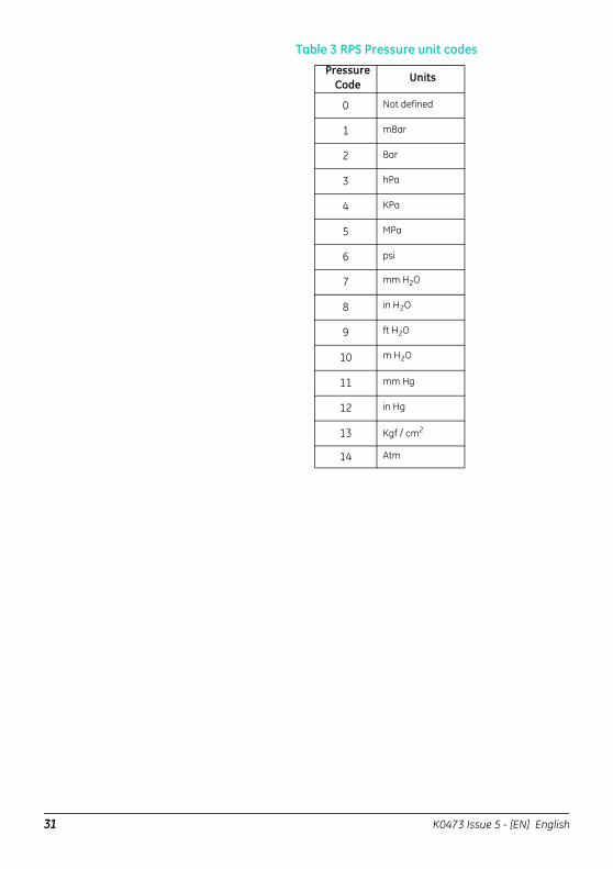
Table 3 RPS Pressure unit codes Pressure
CodeUnits
0 Not defined
1 mBar
2 Bar
3 hPa
4 KPa
5 MPa
6 psi
7 mm H2O
8 in H2O
9 ft H2O
10 m H2O
11 mm Hg
12 in Hg
13 Kgf / cm2
14 Atm
31 K0473 Issue 5 - [EN] English

[EN] English - K0473 Issue 5 32