Embed Size (px)
Citation preview
OFFSHORE STANDARD
DET NORSKE VERITAS
DNV-OS-C103
STRUCTURAL DESIGN OF COLUMN STABILISED UNITS (LRFD METHOD)
APRIL 2004
Since issued in print (April 2004), this booklet has been amended, latest in April 2005. See the reference to “Amendments and Corrections” on the next page.
FOREWORDDET NORSKE VERITAS (DNV) is an autonomous and independent foundation with the objectives of safeguarding life, prop-erty and the environment, at sea and onshore. DNV undertakes classification, certification, and other verification and consultancyservices relating to quality of ships, offshore units and installations, and onshore industries worldwide, and carries out researchin relation to these functions.DNV Offshore Codes consist of a three level hierarchy of documents:— Offshore Service Specifications. Provide principles and procedures of DNV classification, certification, verification and con-
sultancy services.— Offshore Standards. Provide technical provisions and acceptance criteria for general use by the offshore industry as well as
the technical basis for DNV offshore services.— Recommended Practices. Provide proven technology and sound engineering practice as well as guidance for the higher level
Offshore Service Specifications and Offshore Standards.DNV Offshore Codes are offered within the following areas:A) Qualification, Quality and Safety MethodologyB) Materials TechnologyC) StructuresD) SystemsE) Special FacilitiesF) Pipelines and RisersG) Asset OperationH) Marine OperationsJ) Wind Turbines
Amendments and Corrections This document is valid until superseded by a new revision. Minor amendments and corrections will be published in a separatedocument normally updated twice per year (April and October). For a complete listing of the changes, see the “Amendments and Corrections” document located at: http://webshop.dnv.com/global/, under category “Offshore Codes”.
The electronic web-versions of the DNV Offshore Codes will be regularly updated to include these amendments and corrections.E
Comments may be sent by e-mail to [email protected] subscription orders or information about subscription terms, please use [email protected] information about DNV services, research and publications can be found at http://www.dnv.com, or can be obtained from DNV, Veritasveien 1, NO-1322 Høvik, Norway; Tel +47 67 57 99 00, Fax +47 67 57 99 11.
© Det Norske Veritas. All rights reserved. No part of this publication may be reproduced or transmitted in any form or by any means, including photocopying and recording, without the prior written consent of Det Norske Veritas.
Computer Typesetting (FM+SGML) by Det Norske Veritas.Printed in Norway.
If any person suffers loss or damage which is proved to have been caused by any negligent act or omission of Det Norske Veritas, then Det Norske Veritas shall pay compensation to such personfor his proved direct loss or damage. However, the compensation shall not exceed an amount equal to ten times the fee charged for the service in question, provided that the maximum compen-sation shall never exceed USD 2 million.In this provision "Det Norske Veritas" shall mean the Foundation Det Norske Veritas as well as all its subsidiaries, directors, officers, employees, agents and any other acting on behalf of DetNorske Veritas.
Amended April 2005 Offshore Standard DNV-OS-C103, April 2004see note on front cover Changes – Page 3
Main changes
• GeneralThe present edition supersedes the October 2000 edition.• Main changesThe main changes are:
— Sec.1 has been aligned with other relevant structuralstandards (e.g. references, terminology, definitions, etc.)and with DNV-OS-C101.
— Definition and application of design temperature havebeen updated. The term service temperature has beenintroduced.
— Formulations relating to tank pressures have been simpli-fied and clarified.
— Amendments have been introduced in connection with theselection of load factors, contingency factors and the
selection of design waves.
Corrections and ClarificationsIn addition to the above mentioned changes, a number of cor-rections and clarifications have been made to the existing text.
Errata2004-06-01The equation for ps in Sec.3 E202, page 14, has been correctedto include Cw - reduction factor due to wave particle motion.
ps ρ g0Cw TE zb–( ) kNm2( ) 0 ≥=
DET NORSKE VERITAS
Offshore Standard DNV-OS-C103, April 2004 Amended April 2005Page 4 – Changes see note on front cover
DET NORSKE VERITAS
Amended April 2005 Offshore Standard DNV-OS-C103, April 2004see note on front cover Contents – Page 5
CONTENTS
Sec. 1 Introduction........................................................... 7
A. General....................................................................................7A 100 General.............................................................................. 7A 200 Objectives ......................................................................... 7A 300 Assumptions and applications .......................................... 7A 400 Classification .................................................................... 7
B. References ..............................................................................7B 100 General.............................................................................. 7
C. Definitions ..............................................................................7C 100 Verbal forms ..................................................................... 7C 200 Terms ................................................................................ 8
D. Symbols ..................................................................................8D 100 Symbols ............................................................................ 8D 200 Abbreviations.................................................................... 8
Sec. 2 Structural Categorisation, Material Selection and Inspection Principles ..... 9
A. General....................................................................................9A 100 Scope................................................................................. 9
B. Structural Categorisation ........................................................9B 100 Structural categorisation ................................................... 9
C. Material Selection...................................................................9C 100 General.............................................................................. 9C 200 Design and service temperatures ...................................... 9
D. Inspection Categories ...........................................................10D 100 General............................................................................ 10
E. Categorisation and Inspection Level for Typical Column-Stabilised Unit Details...............................10
E 100 General............................................................................ 10
Sec. 3 Design Loads ....................................................... 13
A. Introduction ..........................................................................13A 100 General............................................................................ 13
B. Definition..............................................................................13B 100 Load point ....................................................................... 13
C. Permanent Loads (G)............................................................13C 100 General............................................................................ 13
D. Variable Functional Loads (Q) .............................................13D 100 General............................................................................ 13D 200 Lifeboat platforms........................................................... 13D 300 Tank loads....................................................................... 13
E. Environmental Loads (E)......................................................14E 100 General............................................................................ 14E 200 Sea pressures................................................................... 14E 300 Wind loads ...................................................................... 14E 400 Heavy components.......................................................... 14
F. Deformation Loads (D) ........................................................14F 100 General............................................................................ 14
G. Accidental Loads (A)............................................................15G 100 General............................................................................ 15
H. Fatigue Loads .......................................................................15H 100 General............................................................................ 15
I. Combination of Loads ..........................................................15I 100 General............................................................................ 15
Sec. 4 Ultimate Limit States (ULS) .............................. 16
A. General..................................................................................16A 100 General............................................................................ 16
A 200 Global capacity ............................................................... 16A 300 Transit condition............................................................. 16
B. Method of Analysis...............................................................16B 100 General............................................................................ 16
C. Scantlings and Weld Connections ........................................17C 100 General............................................................................ 17
D. Air Gap .................................................................................17D 100 General............................................................................ 17
Sec. 5 Fatigue Limit States (FLS) ................................ 18
A. General..................................................................................18A 100 General............................................................................ 18
B. Fatigue Analysis ...................................................................18B 100 General............................................................................ 18B 200 World-wide operation..................................................... 18B 300 Restricted operation ....................................................... 18B 400 Simplified fatigue analysis ............................................. 18B 500 Stochastic fatigue analysis .............................................. 19
Sec. 6 Accidental Limit States (ALS)........................... 20
A. General..................................................................................20A 100 General............................................................................ 20
B. Collision................................................................................20B 100 General............................................................................ 20
C. Dropped Object.....................................................................20C 100 General............................................................................ 20
D. Fire........................................................................................20D 100 General............................................................................ 20
E. Explosion ..............................................................................20E 100 General............................................................................ 20
F. Heeled Condition ..................................................................21F 100 General............................................................................ 21
Sec. 7 Special Considerations ....................................... 22
A. Redundancy ..........................................................................22A 100 General............................................................................ 22A 200 Brace arrangements ........................................................ 22
B. Support of Mooring Equipment, Towing Brackets etc.........22B 100 Structural Strength .......................................................... 22
C. Structural Details ..................................................................22C 100 General............................................................................ 22
App. A Permanently Installed Units .............................. 23
A. Introduction...........................................................................23A 100 Application ..................................................................... 23
B. Inspection and Maintenance .................................................23B 100 Facilities for inspection on location................................ 23
C. Fatigue ..................................................................................23C 100 Design fatigue factors ..................................................... 23C 200 Splash zone ..................................................................... 23
App. B Methods and Models for Design of Column-Stabilised Units 25
A. Methods and Models.............................................................25A 100 General............................................................................ 25A 200 World wide operation ..................................................... 25A 300 Benign waters or restricted areas.................................... 25
DET NORSKE VERITAS

Offshore Standard DNV-OS-C103, April 2004 Amended April 2005Page 6 – Contents see note on front cover
DET NORSKE VERITAS
Amended April 2005 Offshore Standard DNV-OS-C103, April 2004see note on front cover Sec.1 – Page 7
SECTION 1INTRODUCTION
A. General
A 100 General101 This offshore standard provides requirements and guid-ance for the structural design of column-stabilised units, con-structed in steel.102 The standard has been written for general world-wideapplication. Governmental regulations may include require-ments in excess of the provisions given by this standarddepending on the size, type, location and intended service of anoffshore unit or installation.
A 200 Objectives201 The objectives of this standard are to:
— provide an internationally acceptable standard of safety bydefining minimum requirements for design of column-sta-bilised units
— serve as a contractual reference document between suppli-ers and purchasers
— serve as a guideline for designers, suppliers, purchasersand regulators
— specify procedures and requirements for column-stabi-lised units subject to DNV verification.
A 300 Assumptions and applications301 The requirements and guidance documented in thisstandard are generally applicable to all configurations of col-umn-stabilised units, including those with:
— ring pontoons— twin pontoons.
302 A column-stabilised unit is a floating structure that canbe relocated. A column-stabilised unit normally consists of adeck box with a number of widely spaced, large diameter, sup-porting columns that are attached to submerged pontoons.303 Column-stabilised unit may be kept on station by eithera passive mooring system, e.g. anchor lines, or an active moor-ing system, e.g. thrusters, or a combination of these methods.304 Requirements concerning mooring and riser systems arenot considered in this standard. 305 A column-stabilised unit may be designed to function ina number of modes, e.g. transit, operational and survival. Lim-iting design criteria modes of operation shall be clearly estab-lished and documented. Such limiting design criteria shallinclude relevant consideration of the following items:
— intact condition, structural strength— damaged condition, structural strength— air gap— watertight integrity and hydrostatic stability.
306 For novel designs, or unproved applications of designswhere limited or no direct experience exists, relevant analysesand model testing, shall be performed to clearly demonstratethat an acceptable level of safety is obtained.
A 400 Classification401 Classification principles, procedures and applicableclass notations related to classification services of offshoreunits are specified in the DNV Offshore Service Specifications
given in Table A1.
402 Documentation requirements for classification are givenby DNV-RP-A202.403 Technical requirements given in DNV-OS-C101, sec-tion 8, related to Serviceability Limit States, are not mandatoryas part of classification.
B. ReferencesB 100 General101 The Offshore Standards, Recommended Practices andClassification Notes given in Table B1 are referred to in thisstandard.
C. DefinitionsC 100 Verbal forms101 Shall: Indicates a mandatory requirement to be followedfor fulfilment or compliance with the present standard. Devia-tions are not permitted unless formally and rigorously justified,and accepted by all relevant contracting parties.102 Should: Indicates a recommendation that a certaincourse of action is preferred or particularly suitable. Alterna-tive courses of action are allowable under the standard whereagreed between contracting parties but shall be justified and
Table A1 DNV Offshore Service SpecificationsReference TitleDNV-OSS-101 Rules for Classification of Drilling and Support
UnitsDNV-OSS-102 Rules for Classification of Production and
Storage Units
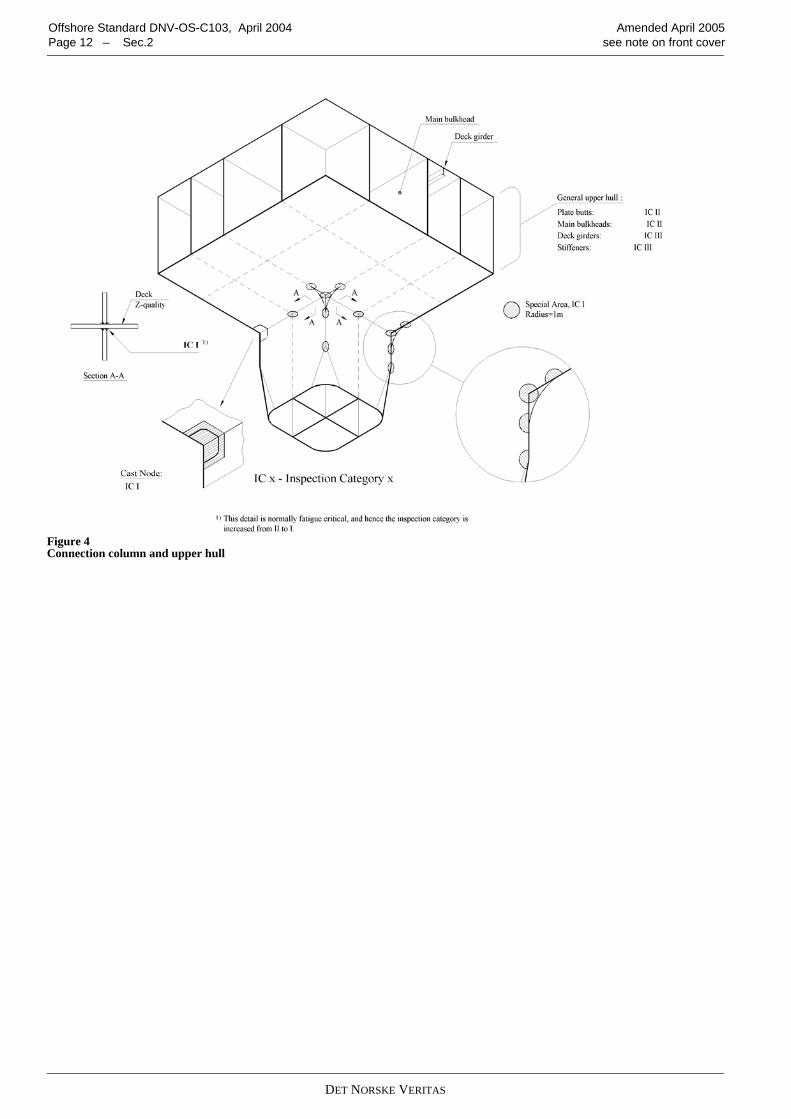
Table B1 DNV Offshore Standards, Classification Notes and Recommended PracticesReference TitleDNV-OS-A101 Safety Principles and ArrangementDNV-OS-B101 Metallic MaterialsDNV-OS-C101 Design of Offshore Steel Structures,
General (LRFD method)DNV-OS-C301 Stability and Watertight IntegrityDNV-OS-C401 Fabrication and Testing of Offshore StructuresDNV-OS-D101 Marine and Machinery Systems and EquipmentDNV-OS-D301 Fire ProtectionDNV-OS-E301 Position MooringDNV-RP-C103 Column-stabilised UnitsDNV-RP-C201 Buckling of Plated StructuresDNV-RP-C202 Buckling Strength of ShellsDNV-RP-C203 Fatigue Strength AnalysisClassification Note 30.1 Sec. 2
Buckling Strength Analysis (Bars and Frames)
Classification Note 30.5
Environmental Conditions and Environmental Loads
Classification Note 30.6
Structural Reliability Analysis of Marine Struc-turesRules for Planning and Execution of Marine Operations
DET NORSKE VERITAS
Offshore Standard DNV-OS-C103, April 2004 Amended April 2005Page 8 – Sec.1 see note on front cover
documented.103 May: Indicates a permission, or an option, which is per-mitted as part of conformance with the standard.
C 200 Terms201 Transit conditions: All unit movements from one geo-graphical location to another.202 Standard terms are given in DNV-OS-C101.
D. Symbols
D 100 Symbols101 Latin characters 102 Greek characters
D 200 Abbreviations201 Abbreviations used in this standard are given in DNV-OS-C101.
= the intercept of the design S-N curve with the log N axis
ah = horizontal acceleration av = vertical acceleration g0 = 9.81 m/s2 acceleration due to gravityh = Weibull shape parameterhop = vertical distance from the load point to the position
of maximum filling heightM = mass of cargo, equipment or other componentsm = the inverse slope of the S-N curven0 = total number of stress fluctuations during the life-
time of the structureni = number of stress fluctuations in i yearspd = design pressure pdyn = pressure head due to flow through pipes
a
zb = vertical distance in m from the moulded baseline to the load point
Cw = reduction factor due to wave particle motion (Smith effect)
DD = vertical distance from the moulded baseline to the underside of the deck structure
DFF = Design Fatigue FactorPHd = horizontal design forcePVd = vertical design forceTE = extreme operational draught measured vertically
from the moulded baseline to the assigned load waterline.
Γ = gamma function α = angleρ = densityγc = contingency factorτd = nominal design shear stress in the girder adjusted
for cut-outs γf = partial load factor γf,E = partial load factor for environmental loadsγf,G,Q = partial load factor for functional and variable loads.
DET NORSKE VERITAS
Amended April 2005 Offshore Standard DNV-OS-C103, April 2004see note on front cover Sec.2 – Page 9
SECTION 2STRUCTURAL CATEGORISATION,
MATERIAL SELECTION AND INSPECTION PRINCIPLES
A. GeneralA 100 Scope101 This section describes the structural categorisation,selection of steel materials and inspection principles to beapplied in design and construction of column-stabilised units.102 The structural application categories are determinedbased on the structural significance, consequences of failureand the complexity of the joints. The structural application cat-egory set the selection of steel quality and the inspection extentof the welds.103 The steel grades selected for structural components shallbe related to weldability and requirements for toughness prop-erties and shall be in compliance with the requirements givenin the DNV-OS-B101.
B. Structural CategorisationB 100 Structural categorisation101 Application categories for structural components aredefined in DNV-OS-C101 Sec.4. Structural members of col-umn-stabilised units are grouped as follows:Special category
a) Portions of deck plating, heavy flanges, and bulkheadswithin the upper hull or platform which form «box» or «I»type supporting structure which receive major concen-trated loads.
b) External shell structure in way of intersections of verticalcolumns, decks and lower hulls.
c) Major intersections of bracing members.d) «Through» material used at connections of vertical col-
umns, upper platform decks and upper or lower hullswhich are designed to provide proper alignment and ade-quate load transfer.
e) External brackets, portions of bulkheads, and frameswhich are designed to receive concentrated loads at inter-sections of major structural members.
f) Highly utilised areas supporting anchor line fairleads andwinches, crane pedestals, flare etc.Guidance note:Highly stressed areas are normally considered to be areas utilisedmore than 85% of the allowable yield capacity.
---e-n-d---of---G-u-i-d-a-n-c-e---n-o-t-e---
Fig.1 to Fig.4 show typical examples of special structures.Primary category
a) Deck plating, heavy flanges, and bulkheads within theupper hull or platform which form «box» or «I» type sup-porting structure which do not receive major concentratedloads.
b) External shell structure of vertical columns, lower andupper hulls, and diagonal and horizontal braces.
c) Bulkheads, decks, stiffeners and girders which providelocal reinforcement or continuity of structure in way ofintersections, except areas where the structure is consid-ered for special application.
d) Main support structure of heavy substructures and equip-ment, e.g. anchor line fairleads, cranes, drillfloor substruc-ture, life boat platform, thruster foundation and helicopterdeck.
Secondary category
a) Upper platform decks, or decks of upper hulls except areaswhere the structure is considered primary or special appli-cation.
b) Bulkheads, stiffeners, flats or decks and girders in verticalcolumns, decks, lower hulls, diagonal and horizontal brac-ing, which are not considered as primary or special appli-cation.
c) Deckhouses.d) Other structures not categorised as special or primary.
C. Material SelectionC 100 General101 Material specifications shall be established for all struc-tural materials. Such materials shall be suitable for theirintended purpose and have adequate properties in all relevantdesign conditions. Material selection shall be undertaken inaccordance with the principles given in DNV-OS-C101.102 When considering criteria appropriate to material gradeselection, adequate consideration shall be given to all relevantphases in the life cycle of the unit. In this connection there maybe conditions and criteria, other than those from the in-serviceoperational phase that provide the design requirements inrespect to the selection of material. (Such criteria may, forexample, be design temperature and/or stress levels duringmarine operations.)103 In structural cross-joints essential for the overall struc-tural integrity where high tensile stresses are acting normal tothe plane of the plate, the plate material shall be tested to provethe ability to resist lamellar tearing (Z-quality).104 Material designations are defined in DNV-OS-C101.
C 200 Design and service temperatures201 The design temperature for a unit is the reference tem-perature for assessing areas where the unit can be transported,installed and operated. The design temperature shall be loweror equal to the lowest mean daily temperature in air for the rel-evant areas. For seasonal restricted operations the lowest meandaily temperature in air for the season may be applied.202 The service temperatures for different parts of a unitapply for selection of structural steel. The service temperaturesare defined as presented in 203 to 206. In case different servicetemperatures are defined in 203 to 206 for a structural part thelower specified value shall be applied.203 External structures above the light transit waterline shallnot be designed for a service temperature higher than thedesign temperature for the unit.However, for column-stabilised units of conventional type, thepontoon deck need not be designed for service temperatureslower than 0ºC.204 External structures below the light transit waterline neednot be designed for service temperatures lower than 0ºC.
DET NORSKE VERITAS
Offshore Standard DNV-OS-C103, April 2004 Amended April 2005Page 10 – Sec.2 see note on front cover
205 Internal structures of columns, pontoons and decks shallhave the same service temperature as the adjacent externalstructure, if not otherwise documented.206 Internal structures in way of permanently heated roomsneed not to be designed for service temperatures lower than0ºC.
D. Inspection CategoriesD 100 General101 Welding and the extent of non-destructive testing duringfabrication, shall be in accordance with the requirements stip-ulated for the appropriate inspection category as defined inDNV-OS-C101, Sec.4.102 Inspection categories determined in accordance withDNV-OS-C101, Sec.4 provide requirements for the minimumextent of required inspection. When considering the economicconsequence that repair during in-service operation may entail,for example, in way of complex connections with limited ordifficult access, it may be considered prudent engineeringpractice to require more demanding requirements for inspec-tion than the required minimum. 103 When determining the extent of inspection and the loca-tions of required NDT, in additional to evaluating designparameters (for example fatigue utilisation), considerationshould be given to relevant fabrication parameters including:
— location of block (section) joints— manual versus automatic welding— start and stop of weld, etc.
E. Categorisation and Inspection Level for Typical Column-Stabilised Unit Details
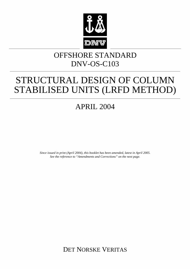
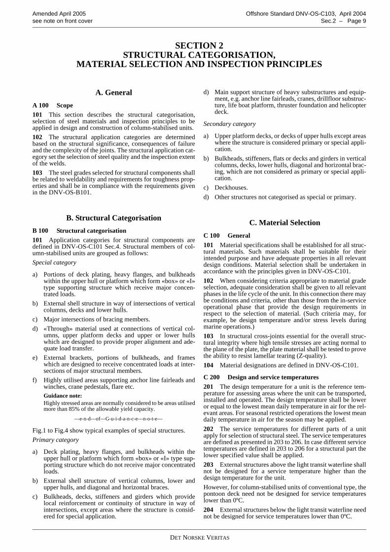
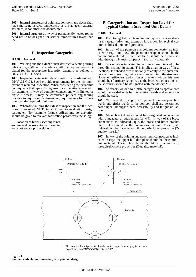
E 100 General101 Fig.1 to Fig.4 illustrate minimum requirements for struc-tural categorisation and extent of inspection for typical col-umn-stabilised unit configurations. 102 In way of the pontoon and column connection as indi-cated in Fig.1 and Fig.2, the pontoon deckplate should be thecontinuous material. These plate fields should be of materialwith through-thickness properties (Z-quality material).103 Shaded areas indicated in the figures are intended to bethree-dimensional in extent. This implies that, in way of theselocations, the shaded area is not only to apply to the outer sur-face of the connection, but is also to extend into the structure.However, stiffeners and stiffener brackets within this areashould be of primary category and the bracket toe locations onthe stiffeners should be designated with mandatory MPI.104 Stiffeners welded to a plate categorised as special areashould be welded with full penetration welds and no notchesshould be used.105 The inspection categories for general pontoon, plate buttwelds and girder welds to the pontoon shell are determinedbased upon, amongst others, accessibility and fatigue utilisa-tion. 106 Major bracket toes should be designated as locationswith a mandatory requirement for MPI. In way of the braceconnections as indicated Fig.3, the brace and brace bracketplate fields should be the continuous material. These platefields should be material with through-thickness properties (Z-quality material). 107 In way of the column and upper hull connection as indi-cated in Fig.4 the upper hull deckplate should be the continu-ous material. These plate fields should be material withthrough-thickness properties (Z-quality material).
Figure 1 Pontoon and column connection, twin pontoon design
Pontoon(Z-Quality)
Column
Around The Column Diam..
Radius 1m
Pontoon Top
Primary Area: IC I
1m
Around The Column Diam..(Z-Quality)Pontoon
Special Area: IC I
Column
1m
increased from II to I, see OS-C101, section 4 C204.This detail is normally fatigue critical, and hence the inspection category is1)
1)
This is normally fatigue critical, an hence the inspection category is increasedfrom II to I, see DNV-OS-C101, Sec.4 C305
DET NORSKE VERITAS
Amended April 2005 Offshore Standard DNV-OS-C103, April 2004see note on front cover Sec.2 – Page 11
Figure 2 Column and ring pontoon connection, ring-pontoon design
Figure 3 Brace connection
DET NORSKE VERITAS
Offshore Standard DNV-OS-C103, April 2004 Amended April 2005Page 12 – Sec.2 see note on front cover
Figure 4 Connection column and upper hull
DET NORSKE VERITAS
Amended April 2005 Offshore Standard DNV-OS-C103, April 2004see note on front cover Sec.3 – Page 13
SECTION 3DESIGN LOADS
A. IntroductionA 100 General101 The requirements in this section define and specify loadcomponents and load combinations to be considered in theoverall strength analysis as well as design pressures applicablefor local design.102 Characteristic loads shall be used as reference loads.Design loads are, in general, defined in DNV-OS-C101 anddescribed in DNV-RP-C103 and Classification Note 30.5.Guidance concerning load categories relevant for column-sta-bilised unit designs are given in this section.
B. DefinitionB 100 Load point101 The load point for which the design pressure for a platefield shall be calculated, is defined as midpoint of a horizon-tally stiffened plate field, and half of the stiffener spacingabove the lower support of vertically stiffened plate field, or atlower edge of plate when the thickness is changed within theplate field.102 The load point for which the design pressure for a stiff-ener shall be calculated, is defined as midpoint of the span.When the pressure is not varied linearly over the span, thedesign pressure shall be taken as the greater of the pressure atthe midpoint, and the average of the pressures calculated ateach end of the stiffener.103 The load point for which the design pressure for a girdershall be calculated, is defined as midpoint of the load area.
C. Permanent Loads (G)C 100 General101 Permanent loads are loads that will not vary in magni-tude, position, or direction during the period considered, andinclude:
— lightweight of the unit, including mass of permanentlyinstalled modules and equipment, such as accommoda-tion, helideck, drilling and production equipment
— hydrostatic pressures resulting from buoyancy— pretension in respect to mooring, drilling and production
systems, e.g. mooring lines, risers etc. See DNV-OS-E301.
D. Variable Functional Loads (Q)D 100 General101 Variable functional loads are loads that may vary inmagnitude, position and direction during the period under con-sideration. 102 Except where analytical procedures or design specifica-tions otherwise require, the value of the variable loads utilisedin structural design shall be taken as either the lower or upperdesign value, whichever gives the more unfavourable effect.Variable loads on deck areas for local design are given inDNV-OS-C101, Sec.3 D200.
103 Variations in operational mass distributions, includingvariations in tank load conditions in pontoons, shall be ade-quately accounted for in the structural design. 104 Design criteria resulting from operational requirementsshall be fully considered. Examples of such operations may be:
— drilling, production, workover, and combinations thereof— consumable re-supply procedures— maintenance procedures— possible mass re-distributions in extreme conditions.
105 Dynamic loads resulting from flow through air pipesduring filling operations shall be adequately considered in thedesign of tank structures.
D 200 Lifeboat platforms201 Structural strength requirements related to lifeboat plat-forms and their supporting structure are given in DNV-OS-C101 Sec.3 D400.
D 300 Tank loads301 A minimum design density (ρ) of 1.025 t/m3 should beconsidered in the determination of the required scantlings oftank structures.302 The extent to which it is possible to fill sounding, vent-ing or loading pipe arrangements shall be fully accounted forin determination of the maximum design pressure to which atank may be subjected to.303 Dynamic pressure heads resulting from filling of suchpipes shall be included in the design pressure head where suchload components are applicable.304 All tanks shall be designed for the following internaldesign pressure:
305 For tanks where the air pipe may be filled during fillingoperations, the following additional internal design pressureconditions shall be considered:
pd = (ρ g0 hop + pdyn) γf,G,Q (kN/m2)
pdyn = Pressure (kN/m2) due to flow through pipes, minimum25 kN/m2.
av = maximum vertical acceleration, (m/s2), being the coupled motion response applicable to the tank in question
hop = vertical distance (m) from the load point to the position of maximum filling height. For tanks adjacent to the sea that are situated below the extreme operational draught (TE), hop should not be taken less than from the load point to the static sea level.Descriptions and requirements related to differ-ent tank arrangements are given in DNV-OS-D101 Ch.2 Sec.3 C300.
γf,G,Q = partial load factor, for permanent and functional loads see Sec.4 Table A1
γf,E = partial load factor for environmental loads, see Sec.4 Table A1.
pd ρ g0⋅ hop γf G Q, ,avg0------γ f E,+⎝
⎛⎠⎞ kN m2
⁄( )=
DET NORSKE VERITAS
Offshore Standard DNV-OS-C103, April 2004 Amended April 2005Page 14 – Sec.3 see note on front cover
Guidance note:This internal pressure need not to be combined with extremeenvironmental loads. Normally only static global response needto be considered.
---e-n-d---of---G-u-i-d-a-n-c-e---n-o-t-e---
306 For external plate field boundaries, it is allowed to con-sider the external pressure up to the lowest waterline occurringin the environmental extreme condition, including relativemotion of the unit.
Guidance note:For preliminary design calculations, av may be taken as 0.3 g0and external pressure for external plate field boundaries may betaken up to half the pontoon height.
---e-n-d---of---G-u-i-d-a-n-c-e---n-o-t-e---
307 In cases where the maximum filling height is less thanthe height to the top of the air pipe, it shall be ensured that thetank will not be over-pressured during operation and tank test-ing conditions.308 Requirements for testing of tank tightness and structuralstrength are given in DNV-OS-C401, Ch.2 Sec.4.
E. Environmental Loads (E)E 100 General101 General considerations for environmental loads aregiven in DNV-OS-C101 Sec.3 E and Sec.3 F, and Classifica-tion Note 30.5. 102 Combinations of environmental loads are stated inDNV-OS-C101 Sec.3 Table F1.103 Typical environmental loads to be considered in thestructural design of a column-stabilised unit are:
— wave loads, including variable pressure, inertia, wave'run-up', and slamming loads
— wind loads— current loads— snow and ice loads.
104 The following responses due to environmental loadsshall be considered in the structural design of a column-stabi-lised unit:
— dynamic stresses for all limit states— rigid body motion, e.g. in respect to air gap and maximum
angles of inclination— sloshing— slamming induced vibrations— vortex induced vibrations,e.g. resulting from wind loads
on structural elements in a flare tower— environmental loads from mooring and riser system.
105 For column-stabilised units with traditional catenarymooring systems, earthquake loads may normally be ignored.
E 200 Sea pressures201 For load conditions where environmental load effectsshall be considered the pressures resulting from sea loading areto include consideration of the relative motion of the unit.202 The design sea pressure acting on pontoons and columnsof column-stabilised platforms in operating conditions shall betaken as:
where
and
203 When pressures are acting on both sides of bulkheads,the load factor shall be applied to the net pressure.204 The Smith effect (Cw = 0.9) shall only be applied forloading conditions including extreme wave conditions.
E 300 Wind loads301 The pressure acting on vertical external bulkheadsexposed to wind shall in general not be taken less than 2.5 kN/m2 for local design.302 Further details regarding wind design loads are given inClassification Note 30.5.
E 400 Heavy components401 The forces acting on supporting structures and lashingsystems for rigid units of cargo, equipment or other structuralcomponents should be taken as:
For components exposed to wind, a horizontal force due to thedesign gust wind shall be added to PHd.
402 Further considerations with respect to environmentalloads are given in Classification Note 30.5.
F. Deformation Loads (D)
F 100 General101 Deformation loads are loads caused by inflicted defor-mations, such as:
— temperature loads— built-in deformations.
pd ps γf G Q , , pe γf E,⋅ +⋅=
ps ρ g0Cw TE zb–( ) kNm2( ) 0 ≥=
TE = extreme operational draught (m) measured verti-cally from the moulded baseline to the assigned load waterline
Cw = reduction factor due to wave particle motion (Smith effect) Cw = 0.9 unless otherwise docu-mented
DD = vertical distance in m from the moulded baseline to the underside of the deck structure(the largest relative distance from moulded base-line to the wave crest may replace DD if this is proved smaller)
zb = vertical distance in m from the moulded baseline to the load point
ps = permanent sea pressurepe = environmental sea pressure.
av = vertical acceleration (m/s2)ah = horizontal acceleration (m/s2)M = mass of cargo, equipment or other components (t) PVd = vertical design forcePHd = horizontal design force.
pe ρg0 Cw DD zb–( ) kNm2( ) for zb TE≥=
pe ρg0 Cw DD TE–( ) kNm2( ) for zb T< E=
PVd g0γf G Q , , avγf E,+( ) M (kN) =
PHd ahγf E, M (kN)=
DET NORSKE VERITAS
Amended April 2005 Offshore Standard DNV-OS-C103, April 2004see note on front cover Sec.3 – Page 15
Further details and description of deformation loads are givenin DNV-OS-C101 Sec.3 H.
G. Accidental Loads (A)G 100 General101 The following ALS events shall be considered in respectto the structural design of a column-stabilised unit:
— collision— dropped objects, e.g. from crane handling— fire— explosion— unintended flooding.
102 Requirements and guidance on accidental loads aregiven in DNV-OS-C101 and generic loads are given in DNV-OS-A101.
H. Fatigue LoadsH 100 General101 Repetitive loads, which may lead to significant fatiguedamage, shall be evaluated. The following listed sources offatigue loads shall, where relevant, be considered:
— waves (including those loads caused by slamming and var-iable (dynamic) pressures).
— wind (especially when vortex induced vibrations mayoccur)
— currents (especially when vortex induced vibrations mayoccur)
— mechanical loading and unloading, e.g. crane loads.
The effects of both local and global dynamic response shall beproperly accounted for when determining response distribu-tions related to fatigue loads.102 Further considerations in respect to fatigue loads aregiven in DNV-RP-C203 and Classification Note 30.5.
I. Combination of LoadsI 100 General101 Load factors and load combinations for the design limitstates are in general, given in DNV-OS-C101.102 Structural strength shall be evaluated considering all rel-evant, realistic load conditions and combinations. Scantlingsshall be determined on the basis of criteria that combine, in arational manner, the effects of relevant global and localresponses for each individual structural element.Further guidance on relevant load combinations is given inDNV-RP-C103.103 A sufficient number of load conditions shall be evalu-ated to ensure that the characteristic largest (or smallest)response, for the appropriate return period, has been estab-lished.
DET NORSKE VERITAS
Offshore Standard DNV-OS-C103, April 2004 Amended April 2005Page 16 – Sec.4 see note on front cover
SECTION 4ULTIMATE LIMIT STATES (ULS)
A. GeneralA 100 General101 General requirements in respect to methods of analysisand capacity checks are given in DNV-OS-C101.Detailed considerations with respect to analysis methods andmodels are given in DNV-RP-C103.102 Both global and local capacity shall be checked withrespect to ULS. The global and local stresses shall be com-bined in an appropriate manner.103 Analytical models shall adequately describe the relevantproperties of loads, stiffness, displacement, response, and sat-isfactorily account for the local system, effects of time depend-ency, damping and inertia.104 Two sets of design load combinations, a) and b) shall bechecked. Partial load factors for ULS checks of column-stabi-lised units according to the present standard are given in TableA1.
105 The loads shall be combined in the most unfavourableway, provided that the combination is physically feasible andpermitted according to the load specifications. For permanentand variable functional loads, a load factor of 1.0 shall be usedin load combination a) where this gives the most unfavourableresponse.106 The material factor γM for ULS yield check should be1.15 for steel structural elements. Material factors γM for ULSbuckling checks and bolt connections are given in DNV-OS-C101 sec.5. Material factors γM for ULS weld connections aregiven in DNV-OS-C101 Sec.9.
A 200 Global capacity201 Gross scantlings may be utilised in the calculation ofhull structural strength, provided a corrosion protection systemin accordance DNV-OS-C101, is maintained.202 Ultimate strength capacity check shall be performed forall structural members contributing to the global and localstrength of the column-stabilised unit. The structures to bechecked includes, but are not limited to, the following:
— outer skin of pontoons— longitudinal and transverse bulkheads, girders and decks
in pontoons— connections between pontoon, columns and bracings— bracings— outer skin of columns— decks, stringers and bulkheads in columns— main bearing bulkheads, frameworks and decks in the
deck structure— connection between bracings and the deck structure — connection between columns and the deck structure
— girders in the deck structure.
A 300 Transit condition301 The structure shall be analysed for zero forward speed.For units in transit with high speed, also maximum speed shallbe considered in the load and strength calculations.
Guidance note:Roll and pitch motion at resonance should be somewhat smallerthan calculated by a linear wave theory due to flow of water ontop of the pontoons. This effect may be accounted for providedrational analysis or tests prove its magnitude.
---e-n-d---of---G-u-i-d-a-n-c-e---n-o-t-e---
302 Slamming on bracings shall be considered as a possiblelimiting criterion for operation in transit. The effect of forwardspeed shall be accounted for in the slamming calculations.
B. Method of AnalysisB 100 General101 The analysis shall be performed to evaluate the struc-tural capacity due to global and local effects. Consideration ofrelevant analysis methods and procedures are given in DNV-RP-C103, and in Appendix B. 102 Model testing shall be performed when significant non-linear effects cannot be adequately determined by direct calcu-lations. In such cases, time domain analysis may also be con-sidered as being necessary. Model tests shall also be performedfor new types of column-stabilised units.103 Where non-linear effects may be considered insignifi-cant, or where such loads may be satisfactorily accounted forin a linear analysis, a frequency domain analysis may be ade-quately and satisfactorily undertaken. Transfer functions forstructural response shall be established by analysis of an ade-quate number of wave directions, with an appropriate radialspacing. A sufficient number of periods shall be analysed to:
— adequately cover the site specific wave conditions— satisfactorily describe transfer functions at, and around,
the wave “cancellation” and “amplifying” periods — satisfactorily describe transfer functions at, and around,
the heave resonance period of the unit.
104 Global, wave-frequency, structural responses shall beestablished by an appropriate methodology, e.g.:
— a regular wave analysis— a “design wave” analysis— a stochastic analysis.
105 Design waves established based on the "design wave"method, see DNV-RP-C103, shall be based on the 90% fractilevalue of the extreme response distribution (100 years returnperiod) developed from contour lines and short term extremeconditions.106 A global structural model shall represent the global stiff-ness and should be represented by a large volume, thin-walledthree dimensional finite element model. A thin-walled modelshould be modelled with shell or membrane elements some-times in combination with beam elements. The structural con-nections in the model shall be modelled with adequatelystiffness in order to represent the actual stiffness in such a waythat the resulting responses are appropriate to the model beinganalysed. The global model usually comprises:
Table A1 Load factors, Ultimate Limit States
Combination of design loads
Load categoriesPermanent and variable func-tional loads,
γf,G,Q
Environmental loads, γf,E
Deformation loads, γf,D
a 1.2 1) 0.7 1.0b 1.0 1.2 1.0
1) If the load is not well defined, e.g. masses or functional loads with great uncertainty, possible overfilling of tanks etc., the coefficient should be increased to 1.3.
DET NORSKE VERITAS
Amended April 2005 Offshore Standard DNV-OS-C103, April 2004see note on front cover Sec.4 – Page 17
— pontoon shell, longitudinal and transverse bulkheads— column shell, decks, bulkheads and trunk walls— main bulkheads, frameworks and decks for the deck struc-
ture (“secondary” decks which are not taking part in theglobal structural capacity should not be modelled)
— bracing and transverse beams.
107 The global analyses should include consideration of thefollowing load effects as found relevant:
— built-in stresses due to fabrication or mating— environmental loads— different ballast conditions including operating and sur-
vival— transit.
108 Wave loads should be analysed by use of sink sourcemodel in combination with a Morison model when relevant.For certain designs a Morison model may be relevant. Detailsrelated to normal practice for selection of models and methodsare given in Appendix B. 109 When utilising stochastic analysis for world wide oper-ation the analyses shall be undertaken utilising North Atlanticscatter diagram given in Classification Note 30.5. 110 For restricted operation the analyses shall be undertakenutilising relevant site specific environmental data for thearea(s) the unit will be operated. The restrictions shall bedescribed in the operation manual for the unit.
C. Scantlings and Weld ConnectionsC 100 General101 Minimum scantlings for plate, stiffeners and girders aregiven in DNV-OS-C101 Sec.5.
102 The requirements for weld connections are given inDNV-OS-C101 Sec.9.
D. Air Gap
D 100 General101 In the ULS condition, positive air gap should in generalbe ensured for waves with a 10-2 annual probability of exeed-ance. However, local wave impact may be accepted if it is doc-umented that such loads are adequately accounted for in thedesign and that safety to personnel is not significantlyimpaired.102 Analysis undertaken to check air gap should be cali-brated against relevant model test results when available. Suchanalysis should take into account:
— wave and structure interaction effects— wave asymmetry effects— global rigid body motions (including dynamic effects)— effects of interacting systems, e.g. mooring and riser sys-
tems— maximum and minimum draughts.
103 Column “run-up” load effects shall be accounted for inthe design of the structural arrangement in the way of the col-umn and bottom plate of the deck connection. These “run-up”loads shall be treated as environmental load component, how-ever, they should not be considered as occurring simultane-ously with other environmental loads.104 Evaluation of sufficient air gap shall include considera-tion of all affected structural items including lifeboat plat-forms, riser balconies, overhanging deck modules etc.
DET NORSKE VERITAS
Offshore Standard DNV-OS-C103, April 2004 Amended April 2005Page 18 – Sec.5 see note on front cover
SECTION 5FATIGUE LIMIT STATES (FLS)
A. GeneralA 100 General101 General requirements for the fatigue limit states aregiven in DNV-OS-C101 Sec.6. Guidance concerning fatiguecalculations are given in DNV-RP-C203.102 Units intended to follow normal inspection requirementsaccording to class requirements, i.e. 5 yearly inspection insheltered waters or drydock, may apply a Design Fatigue Fac-tor (DFF) of 1.0.103 Units intended to stay on location for prolonged surveyperiod, i.e. without planned sheltered water inspection, shallcomply with the requirements given in Appendix A.104 The design fatigue life of the unit shall be minimum 20years. 105 The fatigue capacity of converted units will be consid-ered on a case-by-case basis, and is a function of the followingparameters:
— results and findings form surveys and assessment of criti-cal details
— service history of the unit and estimated remaining fatiguelife.
Guidance note:New structural steel on converted units older than 10 years, maynormally be accepted with minimum 15 years documentedfatigue life from the time of conversion.
---e-n-d---of---G-u-i-d-a-n-c-e---n-o-t-e---
106 Local effects, e.g. due to:
— slamming— sloshing— vortex shedding— dynamic pressures— mooring and riser systems.
shall be included in the fatigue damage assessment when rele-vant.107 In the assessment of fatigue resistance, relevant consid-eration shall be given to the effects of stress concentrationsincluding those occurring as a result of:
— fabrication tolerances, including due regard to tolerancesin way of connections involved in mating sequences orsection joints
— cut-outs— details at connections of structural sections, e.g. cut-outs
to facilitate construction welding— attachments.
108 Local detailed finite element analysis of critical connec-tions, e.g. pontoon and pontoon, pontoon and column, columnand deck and brace connections, should be undertaken in orderto identify local stress distributions, appropriate SCF’s, and/orextrapolated stresses to be utilised in the fatigue evaluation.Dynamic stress variations through the plate thickness shall bechecked and considered in such evaluations, see DNV-RP-C203, for further details.109 For well known details the local finite element analysismay be omitted, provided relevant information regarding SCFare available. 110 Principal stresses, see DNV-RP-C203 Sec.2.2, shouldbe applied in the evaluation of fatigue responses.
B. Fatigue AnalysisB 100 General101 The basis for determining the acceptability of fatigueresistance, with respect to wave loads, shall be in accordancewith the requirements given in Appendix B. The required mod-els and methods are dependent on type of operation, environ-ment and design type of the unit.
B 200 World-wide operation201 For world wide operation the analyses shall be under-taken utilising environmental data, e.g. scatter diagram, spec-trum, given in Classification Note 30.5. The North Atlanticscatter diagram shall be utilised.
B 300 Restricted operation 301 The analyses shall be undertaken utilising relevant sitespecific environmental data for the area(s) the unit will beoperated. The restrictions shall be described in the operationmanual for the unit.
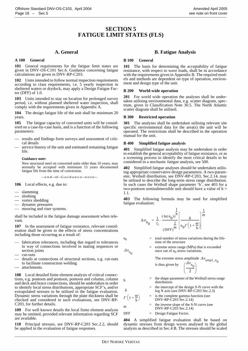
B 400 Simplified fatigue analysis401 Simplified fatigue analysis may be undertaken in orderto establish the general acceptability of fatigue resistance, or asa screening process to identify the most critical details to beconsidered in a stochastic fatigue analysis, see 500. 402 Simplified fatigue analyses should be undertaken utilis-ing appropriate conservative design parameters. A two-param-eter, Weibull distribution, see DNV-RP-C203, Sec.2.14, maybe utilised to describe the long-term stress range distribution.In such cases the Weibull shape parameter ‘h’, see 403 for atwo-pontoon semisubmersible unit should have a value of h =1.1. 403 The following formula may be used for simplifiedfatigue evaluation:
404 A simplified fatigue evaluation shall be based ondynamic stresses from design waves analysed in the globalanalysis as described in Sec.4 B. The stresses should be scaled
n0 = total number of stress variations during the life-time of the structure
= extreme stress range (MPa) that is exceeded once out of n0 stress variations.
The extreme stress amplitude
is thus given by
h = the shape parameter of the Weibull stress range distribution
= the intercept of the design S-N curve with the log N axis (see DNV-RP-C203 Sec.2.3)
= is the complete gamma function (see DNV-RP-C203 Sec.2.14)
m = the inverse slope of the S-N curve (see DNV-RP-C203 Sec.2.14)
DFF = Design Fatigue Factor.
Δσn01γc-----
n0( )ln( )
1h---
DFF( )
1m----
------------------------- a
n0Γ 1 mh----+⎝ ⎠
⎛ ⎞------------------------------
1m----
⋅=
Δσn0Δσampl_n0Δσn0
2------------⎝ ⎠⎜ ⎟⎛ ⎞
a
Γ 1 mh----+⎝ ⎠
⎛ ⎞
DET NORSKE VERITAS
Amended April 2005 Offshore Standard DNV-OS-C103, April 2004see note on front cover Sec.5 – Page 19
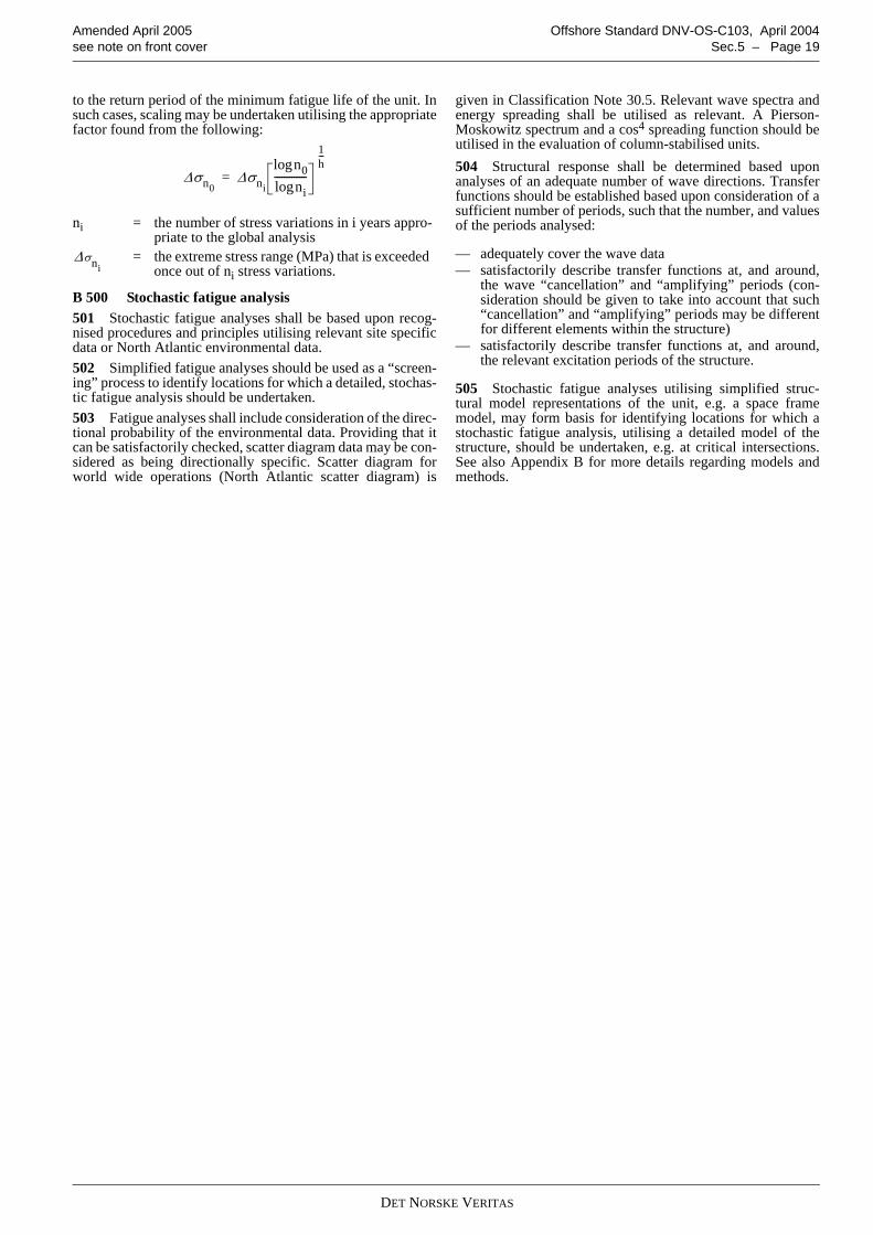
to the return period of the minimum fatigue life of the unit. Insuch cases, scaling may be undertaken utilising the appropriatefactor found from the following:
B 500 Stochastic fatigue analysis501 Stochastic fatigue analyses shall be based upon recog-nised procedures and principles utilising relevant site specificdata or North Atlantic environmental data. 502 Simplified fatigue analyses should be used as a “screen-ing” process to identify locations for which a detailed, stochas-tic fatigue analysis should be undertaken. 503 Fatigue analyses shall include consideration of the direc-tional probability of the environmental data. Providing that itcan be satisfactorily checked, scatter diagram data may be con-sidered as being directionally specific. Scatter diagram forworld wide operations (North Atlantic scatter diagram) is
given in Classification Note 30.5. Relevant wave spectra andenergy spreading shall be utilised as relevant. A Pierson-Moskowitz spectrum and a cos4 spreading function should beutilised in the evaluation of column-stabilised units.504 Structural response shall be determined based uponanalyses of an adequate number of wave directions. Transferfunctions should be established based upon consideration of asufficient number of periods, such that the number, and valuesof the periods analysed:
— adequately cover the wave data— satisfactorily describe transfer functions at, and around,
the wave “cancellation” and “amplifying” periods (con-sideration should be given to take into account that such“cancellation” and “amplifying” periods may be differentfor different elements within the structure)
— satisfactorily describe transfer functions at, and around,the relevant excitation periods of the structure.
505 Stochastic fatigue analyses utilising simplified struc-tural model representations of the unit, e.g. a space framemodel, may form basis for identifying locations for which astochastic fatigue analysis, utilising a detailed model of thestructure, should be undertaken, e.g. at critical intersections.See also Appendix B for more details regarding models andmethods.
ni = the number of stress variations in i years appro-priate to the global analysis
= the extreme stress range (MPa) that is exceeded once out of ni stress variations.
Δσn0Δσni
n0lognilog
-------------
1h---
=
Δσni
DET NORSKE VERITAS
Offshore Standard DNV-OS-C103, April 2004 Amended April 2005Page 20 – Sec.6 see note on front cover
SECTION 6ACCIDENTAL LIMIT STATES (ALS)
A. GeneralA 100 General101 Satisfactory protection against accidental damage shallbe obtained by the following means:
— low damage probability— acceptable damage consequences.
102 The structure’s capability to redistribute loads should beconsidered when designing the structure. The structural integ-rity shall be intact and should be analysed for the followingdamage conditions:
— fracture of braces and major pillars important for the struc-tural integrity, including their joints
— fracture of primary girder in the upper hull.
After damage requiring immediate repair, the unit shall resistfunctional and environmental loads corresponding to a returnperiod of one year.103 Analysis as stated shall satisfy relevant strength criteriagiven in this standard and in DNV-OS-C101. The damage con-sequences of other accidental events shall be specially consid-ered in each case, applying an equivalent standard of safety.
Guidance note:Energy absorption by impact types of accidental events requiresthe structure to behave in a ductile manner. Measures to obtainadequate ductility are:- select materials with sufficient toughness for the actual serv-
ice temperature and thickness of structural members- make the strength of connections of primary members to
exceed the strength of the member itself- provide redundancy in the structure, so that alternate load
redistribution paths may be developed- avoid dependency on energy absorption in slender members
with a non-ductile post buckling behaviour- avoid pronounced weak sections and abrupt change in
strength or stiffness.---e-n-d---of---G-u-i-d-a-n-c-e---n-o-t-e---
104 The loads and consequential damage due to accidentalevents or accidental flooding such as:
— collision— dropped objects, e.g. from crane handling— fire— explosion— unintended flooding— abnormal wave events
shall not cause loss of floatability, capsizing, pollution or lossof human life. Requirements for watertight integrity andhydrostatic stability are given in DNV-OS-C301.
Guidance note:10-4 waves need not to be considered as a ALS condition.
---e-n-d---of---G-u-i-d-a-n-c-e---n-o-t-e---
B. CollisionB 100 General101 A collision between a supply vessel and a column of acolumn-stabilised unit shall be considered for all elements ofthe unit which may be exposed to sideway, bow or stern colli-
sion. The vertical extent of the collision zone shall be based onthe depth and draught of the supply vessel and the relativemotion between the supply vessel and the unit.102 A collision will normally only cause local damage of thecolumn. However, for a unit with slender columns, the globalstrength of the unit shall be checked.103 A collision against a brace will normally cause completefailure of the brace and its connections, e.g. K-joints. Theseparts shall be assumed non-effective for check of the residualstrength of the unit after collision.
C. Dropped ObjectC 100 General101 Critical areas for dropped objects shall be determined onthe basis of the actual movement of potentially dropped objectsrelative to the structure of the unit itself. Where a droppedobject is a relevant accidental event, the impact energy shall beestablished and the structural consequences of the impactassessed.102 A dropped object on a brace will normally cause com-plete failure of the brace or its connections, e.g. K-joints. Theseparts are assumed to be non-effective for the check of the resid-ual strength of the unit after dropped object impact.103 Critical areas for dropped objects shall be determined onthe basis of the actual movement of loads assuming a dropdirection within an angle with the vertical direction:
— 10º in air, for floating units— 5º in air, for bottom supported units— 15º in water.
Dropped objects shall be considered for vital structural ele-ments of the unit within the areas given above.
D. FireD 100 General101 The main loadbearing structure that is subjected to a fireshall not lose the structural capacity. The following fire scenar-ios shall be considered:
— fire inside the unit— fire on the sea surface.
102 Further requirements concerning accidental limit stateevents involving fire is given in DNV-OS-A101.103 Assessment of fire may be omitted provided assump-tions made in DNV-OS-D301 are met.
E. ExplosionE 100 General101 In respect to design, considering loads resulting fromexplosions, one or a combination of the following design phi-losophies are relevant:
— hazardous areas are located in unconfined (open) locationsand that sufficient shielding mechanisms,e.g. blast walls,
DET NORSKE VERITAS
Amended April 2005 Offshore Standard DNV-OS-C103, April 2004see note on front cover Sec.6 – Page 21
are installed— hazardous areas are located in partially confined locations
and the resulting, relatively small overpressures areaccounted for in the structural design
— hazardous areas are located in enclosed locations and pres-sure relief mechanisms are installed, e.g. blast panelsdesigned to take the resulting overpressure.
102 As far as practicable, structural design accounting forlarge plate field rupture resulting from explosion loads shouldbe avoided due to the uncertainties of the loads and the conse-quences of the rupture itself.
F. Heeled ConditionF 100 General101 Heeling of the unit after damage flooding, as describedin DNV-OS-C301 shall be accounted for in the assessment ofstructural strength. Maximum static allowable heel after acci-dental flooding is 17º including wind. Structures that are wetwhen the static equilibrium angle is achieved, shall be checkedfor external water pressure.
Guidance note:The heeled condition corresponding to accidental flooding intransit conditions will normally not be governing for the design.
---e-n-d---of---G-u-i-d-a-n-c-e---n-o-t-e---
102 The unit shall be designed for environmental conditioncorresponding to 1 year return period after damage, see DNV-OS-C101.
Guidance note:The environmental loads may be disregarded if the material fac-tor is taken as γM = 1.33.
---e-n-d---of---G-u-i-d-a-n-c-e---n-o-t-e---
103 Local exceedance of the structural resistance is accepta-ble provided redistribution of forces due to yielding, bucklingand fracture is accounted for.104 Wave pressure, slamming forces and green sea shall beaccounted for in all relevant areas. Local damage may beaccepted provided progressive structural collapse and damageof vital equipment is avoided.105 Position of air-intakes and openings to areas with vitalequipment which need to be available during an emergency sit-uation, e.g. emergency generators, shall be considered takinginto account the wave elevation in a 1 year storm.
DET NORSKE VERITAS
Offshore Standard DNV-OS-C103, April 2004 Amended April 2005Page 22 – Sec.7 see note on front cover
SECTION 7SPECIAL CONSIDERATIONS
A. RedundancyA 100 General101 Structural robustness shall, when considered necessary,be demonstrated by appropriate analysis. Slender, main loadbearing structural elements shall normally be demonstrated tobe redundant in the accidental limit state condition.
A 200 Brace arrangements201 For bracing systems the following listed considerationsshall apply:
— brace structural arrangements shall be investigated for rel-evant combinations of global and local loads
— structural redundancy of slender bracing systems (see 100)shall normally include brace node redundancy, i.e. allbraces entering the node, in addition to individual braceelement redundancy
— brace end connection, e.g. brace and column connections,shall normally be designed such that the brace elementitself will fail before the end connection
— underwater braces shall be watertight and have a leakagedetection system
— the effect of slamming on braces shall be considered, e.g.in transit condition.
B. Support of Mooring Equipment, Towing Brackets etc.
B 100 Structural Strength101 Structure supporting mooring equipment such as fair-leads and winches, towing brackets etc. shall be designed forthe loads and acceptance criteria specified in DNV-OS-E301,Ch.2 Sec.4. Details related to design of supporting structure formooring equipment may be found in DNV-RP-C103.
C. Structural DetailsC 100 General101 In the design phase particular attention should be givento structural details, and requirements for reinforcement inareas that may be subjected to high local stresses, for example:
— critical connections— locations that may be subjected to wave impact (including
wave run-up effects along the columns)— locations in way of mooring arrangements— locations that may be subjected to damage.
102 In way of critical connections, structural continuityshould be maintained through joints with the axial stiffeningmembers and shear web plates being made continuous. Partic-ular attention should be given to weld detailing and geometricform at the point of the intersections of the continuous platefields with the intersecting structure.
DET NORSKE VERITAS
Amended April 2005 Offshore Standard DNV-OS-C103, April 2004see note on front cover App.A – Page 23
APPENDIX A PERMANENTLY INSTALLED UNITS
A. IntroductionA 100 Application101 The requirements and guidance given in this Appendixare supplementary requirements for units that are intended tostay on location for prolonged periods, normally more than 5years, see also DNV-OSS-101 and DNV-OSS-102 for require-ments related to in-service inspections. 102 The requirements apply to all types of column-stabilisedunits.103 Permanently located units shall be designed for site spe-cific environmental criteria for the area(s) the unit will belocated.
B. Inspection and MaintenanceB 100 Facilities for inspection on location101 Inspections may be carried out on location based on pro-cedures outlined in a maintenance system and inspectionarrangement, without interrupting the function of the unit. Thefollowing matters should be taken into consideration to be able
to carry out condition monitoring on location:
— arrangement for underwater inspection of hull, propellers,thrusters and openings affecting the unit’s seaworthiness
— means of blanking of all openings— marking of the underwater hull— use of corrosion resistant materials for propeller— accessibility of all tanks and spaces for inspection— corrosion protection of hull— maintenance and inspection of thrusters— ability to gas free and ventilate tanks— provisions to ensure that all tank inlets are secured during
inspection— testing facilities of all important machinery.
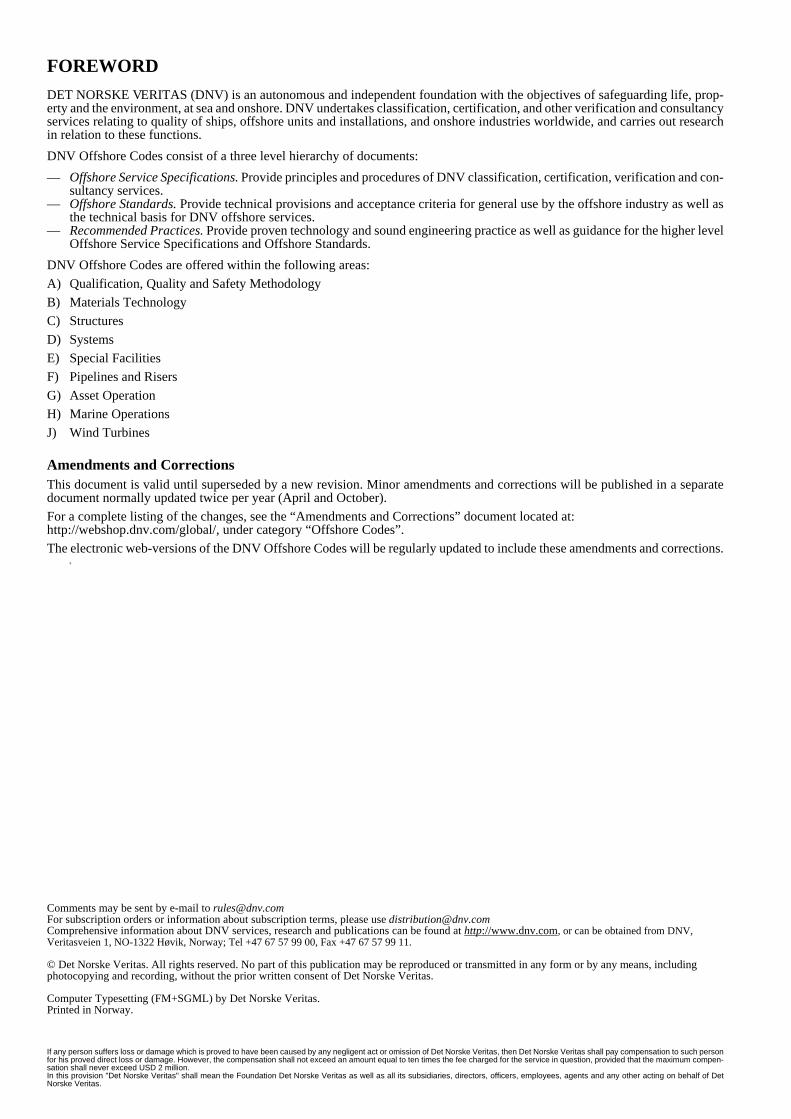
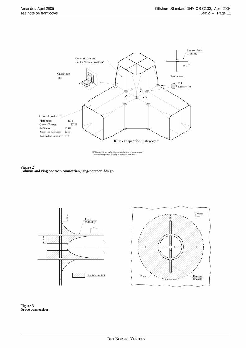
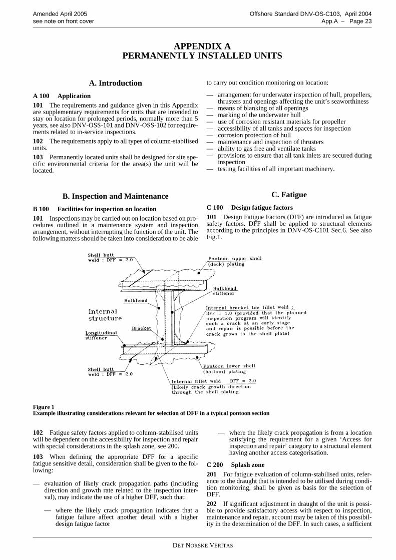
C. FatigueC 100 Design fatigue factors101 Design Fatigue Factors (DFF) are introduced as fatiguesafety factors. DFF shall be applied to structural elementsaccording to the principles in DNV-OS-C101 Sec.6. See alsoFig.1.
Figure 1 Example illustrating considerations relevant for selection of DFF in a typical pontoon section
102 Fatigue safety factors applied to column-stabilised unitswill be dependent on the accessibility for inspection and repairwith special considerations in the splash zone, see 200.103 When defining the appropriate DFF for a specificfatigue sensitive detail, consideration shall be given to the fol-lowing:
— evaluation of likely crack propagation paths (includingdirection and growth rate related to the inspection inter-val), may indicate the use of a higher DFF, such that:
— where the likely crack propagation indicates that afatigue failure affect another detail with a higherdesign fatigue factor
— where the likely crack propagation is from a locationsatisfying the requirement for a given ‘Access forinspection and repair’ category to a structural elementhaving another access categorisation.
C 200 Splash zone201 For fatigue evaluation of column-stabilised units, refer-ence to the draught that is intended to be utilised during condi-tion monitoring, shall be given as basis for the selection ofDFF. 202 If significant adjustment in draught of the unit is possi-ble to provide satisfactory access with respect to inspection,maintenance and repair, account may be taken of this possibil-ity in the determination of the DFF. In such cases, a sufficient
DET NORSKE VERITAS
Offshore Standard DNV-OS-C103, April 2004 Amended April 2005Page 24 – App.A see note on front cover
margin in respect to the minimum inspection draught should beconsidered when deciding upon the appropriate DFF in rela-tion to the criteria for ‘Below splash zone’ as opposed to‘Above splash zone’. Where draught adjustment possibilities
exist, a reduced extent of splash zone may be applicable. 203 Requirements related to vertical extent of splash zoneare given in DNV-OS-C101 Sec.10 B200.
DET NORSKE VERITAS
Amended April 2005 Offshore Standard DNV-OS-C103, April 2004see note on front cover App.B – Page 25
APPENDIX B METHODS AND MODELS FOR DESIGN OF COLUMN-STABILISED UNITS
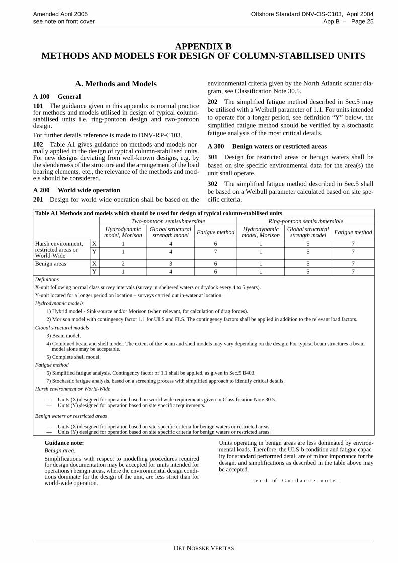
A. Methods and ModelsA 100 General101 The guidance given in this appendix is normal practicefor methods and models utilised in design of typical column-stabilised units i.e. ring-pontoon design and two-pontoondesign.For further details reference is made to DNV-RP-C103.102 Table A1 gives guidance on methods and models nor-mally applied in the design of typical column-stabilised units.For new designs deviating from well-known designs, e.g. bythe slenderness of the structure and the arrangement of the loadbearing elements, etc., the relevance of the methods and mod-els should be considered.
A 200 World wide operation201 Design for world wide operation shall be based on the
environmental criteria given by the North Atlantic scatter dia-gram, see Classification Note 30.5.202 The simplified fatigue method described in Sec.5 maybe utilised with a Weibull parameter of 1.1. For units intendedto operate for a longer period, see definition “Y” below, thesimplified fatigue method should be verified by a stochasticfatigue analysis of the most critical details.
A 300 Benign waters or restricted areas301 Design for restricted areas or benign waters shall bebased on site specific environmental data for the area(s) theunit shall operate.302 The simplified fatigue method described in Sec.5 shallbe based on a Weibull parameter calculated based on site spe-cific criteria.
Guidance note:Benign area:Simplifications with respect to modelling procedures requiredfor design documentation may be accepted for units intended foroperations i benign areas, where the environmental design condi-tions dominate for the design of the unit, are less strict than forworld-wide operation.
Units operating in benign areas are less dominated by environ-mental loads. Therefore, the ULS-b condition and fatigue capac-ity for standard performed detail are of minor importance for thedesign, and simplifications as described in the table above maybe accepted.
---e-n-d---of---G-u-i-d-a-n-c-e---n-o-t-e---
Table A1 Methods and models which should be used for design of typical column-stabilised unitsTwo-pontoon semisubmersible Ring-pontoon semisubmersible
Hydrodynamic model, Morison
Global structural strength model Fatigue method Hydrodynamic
model, MorisonGlobal structural strength model Fatigue method
Harsh environment, restricted areas or World-Wide
X 1 4 6 1 5 7Y 1 4 7 1 5 7
Benign areas X 2 3 6 1 5 7Y 1 4 6 1 5 7
DefinitionsX-unit following normal class survey intervals (survey in sheltered waters or drydock every 4 to 5 years).Y-unit located for a longer period on location – surveys carried out in-water at location.Hydrodynamic models
1) Hybrid model - Sink-source and/or Morison (when relevant, for calculation of drag forces).2) Morison model with contingency factor 1.1 for ULS and FLS. The contingency factors shall be applied in addition to the relevant load factors.
Global structural models3) Beam model. 4) Combined beam and shell model. The extent of the beam and shell models may vary depending on the design. For typical beam structures a beam model alone may be acceptable.5) Complete shell model.
Fatigue method6) Simplified fatigue analysis. Contingency factor of 1.1 shall be applied, as given in Sec.5 B403.7) Stochastic fatigue analysis, based on a screening process with simplified approach to identify critical details.
Harsh environment or World-Wide
— Units (X) designed for operation based on world wide requirements given in Classification Note 30.5. — Units (Y) designed for operation based on site specific requirements.
Benign waters or restricted areas
— Units (X) designed for operation based on site specific criteria for benign waters or restricted areas.— Units (Y) designed for operation based on site specific criteria for benign waters or restricted areas.
DET NORSKE VERITAS