Embed Size (px)
Citation preview

—RELION® PROTECTION AND CONTROL
REF615RDNP3 Communication Protocol Manual


Document ID: 1MRS240048-IBIssued: 2019-07-02
Revision: CProduct version: 4.1
© Copyright 2019 ABB. All rights reserved

Copyright
This document and parts thereof must not be reproduced or copied without writtenpermission from ABB, and the contents thereof must not be imparted to a third party, norused for any unauthorized purpose.
The software or hardware described in this document is furnished under a license and maybe used, copied, or disclosed only in accordance with the terms of such license.
TrademarksABB and Relion are registered trademarks of the ABB Group. All other brand or productnames mentioned in this document may be trademarks or registered trademarks of theirrespective holders.
WarrantyPlease inquire about the terms of warranty from your nearest ABB representative.
www.abb.com/mediumvoltage
www.abb.com/substationautomation

Disclaimer
The data, examples and diagrams in this manual are included solely for the concept orproduct description and are not to be deemed as a statement of guaranteed properties. Allpersons responsible for applying the equipment addressed in this manual must satisfythemselves that each intended application is suitable and acceptable, including that anyapplicable safety or other operational requirements are complied with. In particular, anyrisks in applications where a system failure and/or product failure would create a risk forharm to property or persons (including but not limited to personal injuries or death) shallbe the sole responsibility of the person or entity applying the equipment, and those soresponsible are hereby requested to ensure that all measures are taken to exclude ormitigate such risks.
This product has been designed to be connected and communicate data and informationvia a network interface which should be connected to a secure network. It is the soleresponsibility of the person or entity responsible for network administration to ensure asecure connection to the network and to take the necessary measures (such as, but notlimited to, installation of firewalls, application of authentication measures, encryption ofdata, installation of anti virus programs, etc.) to protect the product and the network, itssystem and interface included, against any kind of security breaches, unauthorized access,interference, intrusion, leakage and/or theft of data or information. ABB is not liable forany such damages and/or losses.
This document has been carefully checked by ABB but deviations cannot be completelyruled out. In case any errors are detected, the reader is kindly requested to notify themanufacturer. Other than under explicit contractual commitments, in no event shall ABBbe responsible or liable for any loss or damage resulting from the use of this manual or theapplication of the equipment.

Conformity
This product complies with the directive of the Council of the European Communities onthe approximation of the laws of the Member States relating to electromagneticcompatibility (EMC Directive 2004/108/EC) and concerning electrical equipment for usewithin specified voltage limits (Low-voltage directive 2006/95/EC). This conformity isthe result of tests conducted by ABB in accordance with the product standards EN 50263and EN 60255-26 for the EMC directive, and with the product standards EN 60255-1 andEN 60255-27 for the low voltage directive. The product is designed in accordance with theinternational standards of the IEC 60255 series and ANSI C37.90. The DNP3 protocolimplementation in this product conforms to "DNP3 Intelligent Electronic Device (IED)Certification Procedure Subset Level 2", available at www.dnp.org. This productcomplies with the UL 508 certification.

Table of contents
Section 1 Introduction............................................................................3This manual.............................................................................................. 3Intended audience.................................................................................... 3Product documentation.............................................................................4
Product documentation set..................................................................4Document revision history................................................................... 4Related documentation........................................................................4
Symbols and conventions.........................................................................5Symbols...............................................................................................5Document conventions........................................................................ 5
Section 2 DNP3 overview......................................................................7DNP3 standard......................................................................................... 7
Physical layer.......................................................................................7Data link layer......................................................................................7Transport pseudo-layer....................................................................... 8Application layer parameters............................................................... 9Communication modes........................................................................9
Section 3 Vendor-specific implementation.......................................... 11DNP3 link modes.................................................................................... 11
DNP3 data objects.............................................................................11DNP3 serial link mode....................................................................... 11DNP3 TCP/IP mode...........................................................................12
DNP3 point settings................................................................................12Binary input points............................................................................. 12Binary output status points and control relay output blocks.............. 12
CROB index (point) types.............................................................13Control modes.............................................................................. 14Binary output status points........................................................... 16
Analog inputs.....................................................................................17Analog data scaling...................................................................... 18Fault record time stamp................................................................19
DNP3 points............................................................................................20Point configuration.............................................................................20Class assignment.............................................................................. 20
Table of contents
REF615R 1Communication Protocol Manual

Section 4 DNP3 parameters................................................................23Parameter descriptions...........................................................................23Parameter list..........................................................................................26
Section 5 Tolerances...........................................................................29DNP3 timing considerations................................................................... 29
Section 6 Glossary.............................................................................. 31
Table of contents
2 REF615RCommunication Protocol Manual

Section 1 Introduction
1.1 This manual
The communication protocol manual describes a communication protocol supported bythe protection relay. The manual concentrates on vendor-specific implementations.
1.2 Intended audience
This manual addresses the communication system engineer or system integratorresponsible for pre-engineering and engineering the communication setup in a substationfrom a protection relay's perspective.
The system engineer or system integrator must have a basic knowledge of communicationin protection and control systems and thorough knowledge of the specific communicationprotocol.
1MRS240048-IB C Section 1Introduction
REF615R 3Communication Protocol Manual

1.3 Product documentation
1.3.1 Product documentation set
Pla
nnin
g &
pu
rcha
se
Eng
inee
ring
Inst
alla
tion
Com
mis
sion
ing
Ope
ratio
n
Mai
nten
ance
Dec
omm
issi
onin
g,de
inst
alla
tion
& d
ispo
sal
Quick installation guideBrochureProduct guideOperation manualInstallation manualEngineering manualTechnical manualApplication manualCommunication protocol manualIEC 61850 engineering guidePoint list manual
GUID-3983CF6E-DF22-4183-B387-D67F3BB9593C V1 EN
Figure 1: The intended use of documents during the product life cycle
1.3.2 Document revision historyDocument revision/date Product version HistoryA/2013-11-22 4.0 First release
B/2016-10-24 4.1 Content updated to correspond to theproduct version
C/2019-07-02 4.1 Content updated
Download the latest documents from the ABB Web sitehttp://www.abb.com/substationautomation.
1.3.3 Related documentationName of the document Document IDDNP3 Point List Manual 1MRS240051-IB
Section 1 1MRS240048-IB CIntroduction
4 REF615RCommunication Protocol Manual

Product-specific point list manuals and other product series- and product-specificmanuals can be downloaded from the ABB Web sitehttp://www.abb.com/substationautomation.
The purpose of this document is to describe specific configuration and interoperabilityinformation for an implementation of the Distributed Network Protocol, Version 3.0. Thisdocument, in conjunction with the DNP3 Basic 4 Document Set, and the DNP SubsetDefinitions Document, provides complete information on how to communicate via theDNP3 protocol.
1.4 Symbols and conventions
1.4.1 Symbols
The caution icon indicates important information or warning related to theconcept discussed in the text. It might indicate the presence of a hazardwhich could result in corruption of software or damage to equipment orproperty.
The information icon alerts the reader of important facts and conditions.
The tip icon indicates advice on, for example, how to design your projector how to use a certain function.
Although warning hazards are related to personal injury, it is necessary to understand thatunder certain operational conditions, operation of damaged equipment may result indegraded process performance leading to personal injury or death. Therefore, complyfully with all warning and caution notices.
1.4.2 Document conventions
A particular convention may not be used in this manual.
• Abbreviations and acronyms are spelled out in the glossary. The glossary alsocontains definitions of important terms.
• Push button navigation in the LHMI menu structure is presented by using the pushbutton icons.
1MRS240048-IB C Section 1Introduction
REF615R 5Communication Protocol Manual

To navigate between the options, use and .• Menu paths are presented in bold.
Select Main menu/Settings.• WHMI menu names are presented in bold.
Click Information in the WHMI menu structure.• LHMI messages are shown in Courier font.
To save the changes in nonvolatile memory, select Yes and press .• Parameter names are shown in italics.
The function can be enabled and disabled with the Operation setting.• Parameter values are indicated with quotation marks.
The corresponding parameter values are "Enabled" and "Disabled".• Input/output messages and monitored data names are shown in Courier font.
When the function picks up, the PICKUP output is set to TRUE.• Dimensions are provided both in inches and mm. If it is not specifically mentioned,
the dimension is in mm.
Section 1 1MRS240048-IB CIntroduction
6 REF615RCommunication Protocol Manual
Section 2 DNP3 overview
2.1 DNP3 standard
The DNP3 protocol was developed by Westronic based on the early versions of the IEC60870-5 standard telecontrol protocol specifications. Now the protocol specification iscontrolled by the DNP Users Group at www.dnp.org.
The ISO/OSI based model supported by this protocol specifies physical, data link andapplication layers only. This reduced protocol stack is referred to as EPA. However, tosupport advanced RTU functions and messages larger than the maximum frame length asdefined by the IEC document 60870-5-1, the DNP3 data link is intended to be used witha transport pseudo-layer. As a minimum, this transport layer implements messageassembly and disassembly services.
2.1.1 Physical layer
There are two specified physical layer modes; serial and Ethernet.
Additional information on the DNP3 physical layer is available at theDNP Users Group at www.dnp.org.
2.1.2 Data link layer
The DNP3 data link layer is designed to operate with connection-oriented andconnectionless asynchronous or synchronous bit serial physical layers. Fully balancedtransmission procedures were adopted to support spontaneous transmissions fromoutstations.
Data link functions:
• Performing message data link retransmissions.• Synchronizing and handling the FCB in the control octet.• Setting and clearing the DFC bit based on buffer availability.• Packing user data into the defined frame format, include CRC checksums and
transmitting the data to the physical layer.• Unpacking the data link frame received from the physical layer into user data, check
and remove CRC checksums.
1MRS240048-IB C Section 2DNP3 overview
REF615R 7Communication Protocol Manual

• Controlling all aspects of the physical layer.• In unsolicited reporting mode, performing collision avoidance/detection procedures
to ensure reliable transfer of data across the physical link.• Responding to all valid frames received from the physical layer.
Data link responsibilities:
• Exchange of SDUs between peer DNP3 data links• Error notification to data link user• Sequencing of SDUs• SDU delivery quality.
Link-layer confirm usage is deprecated.
See the DNP3 technical bulletin TB1998-0402, section 3 for details atwww.dnp.org.
2.1.3 Transport pseudo-layer
To support advanced RTU functions and messages exceeding the maximum data linkframe length, a transport pseudo-layer which implements message assembly anddisassembly services was adopted. This pseudo-layer is actually a super-data linktransport protocol, which is normally included in some OSI protocol data links.
Transport functions:
• Fragmenting user data into one or more data link frames and transmitting the data tothe data link layer
• Assembling the data link frames received from the data link layer into user data• Controlling all aspects of the data link excluding data link configuration
Transport responsibilities:
• Exchange of SDUs between peer DNP3 transport pseudo layers• Error notification to transport users• Sequencing of SDUs
Section 2 1MRS240048-IB CDNP3 overview
8 REF615RCommunication Protocol Manual

2.1.4 Application layer parameters
When App layer confirm is disabled, the protection relay requests applicationconfirmation for event messages only. When it is enabled, the protection relay alsorequests application confirmations for all the sent application.
App confirm TO is the application layer confirmation timeout in milliseconds. Applicationlayer confirmations received from the master after App confirm TO has expired are notacknowledged by the protection relay. It applies to both solicited and unsolicited events.
App layer fragment is the application layer fragment size in bytes.
CROB select timeout is the DNP3 selecting before operating timer.
2.1.5 Communication modes
The protection relay supports three DNP3 communication modes.
• Polled static mode, meaning that the master polls for class 0 or static data only• Polled report by exception mode, where the Master polls for change events (class
1,2,3) and occasionally makes integrity polls (class 1, 2, 3, 0)• Unsolicited report by exception mode, where the slave reports change events
spontaneously without being polled by the master. Master occasionally makesintegrity polls (class 1, 2, 3, 0).
1MRS240048-IB C Section 2DNP3 overview
REF615R 9Communication Protocol Manual

10

Section 3 Vendor-specific implementation
3.1 DNP3 link modes
Serial and TCP/IP modes are available. They are mutually exclusive.
3.1.1 DNP3 data objects
The DNP3 protocol in 615 series protection relays is built on top of the internal IEC 61850data model. Thus, the DNP3 application data objects and Class events are derived fromIEC 61850 data objects and data set reporting. The 615 series protection relays have apredefined IEC 61850 data set configuration. In other words, it is predefined whichinternal data object changes the 615 series protection relays detect.
The available DNP3 data objects in the 615 series protection relays are selected from theobjects predefined in the IEC 61850 data sets.
For a list of the available data objects, see the point list manual.
3.1.2 DNP3 serial link mode
DNP3 serial can be assigned to a serial communication port in the protection relay. Serialcommunication ports are named COM1...COMn, depending on how many serial ports the615 series protection relay hosts.
If this protocol does not operate as expected, check that other serialprotocols are not using the COM port also.
DNP3 protocol ignores any parity setting in the COM settings group;DNP3 is defined as an 8 bit/no parity protocol with a 16-bit CRC every 16bytes. This provides better error detection than parity.
1MRS240048-IB C Section 3Vendor-specific implementation
REF615R 11Communication Protocol Manual

3.1.3 DNP3 TCP/IP mode
DNP3 TCP/IP link mode is supported by the protection relay.
The protection relay listens for a connection from a DNP3 master on port 20000. A singleDNP3 session can be run concurrently with IEC 61850, Modbus Serial and/or ModbusTCP. Documentation concerning DNP3 TCP/IP communication is available fromwww.dnp.org.
3.2 DNP3 point settings
3.2.1 Binary input points
The binary input event buffer size is set to allow 200 events. Events that occur after bufferoverflow are discarded.
Table 1: Binary input points
Description ValueStatic (steady-state) object number 1
Static variation reported when variation 0 requested(default setting)
1 (binary input without status)
Change event object number 2
Change event variation reported when variation 0requested (default setting)
2 (binary input change with time)
Table 2: Default Class assignment for Binary Input points
Point index Name/description Default change event assigned class (1, 2, 3 or none) See the DNP3 point list manual.
3.2.2 Binary output status points and control relay output blocks
The binary output status points (object 10) and the CROBs (object 12) are provided in theconfiguration specific point list.
Operation of the DNP3 control commands is blocked unless the relay isset to remote control mode. Count, off-time and on-time in the commandfields are not supported in this implementation.
Section 3 1MRS240048-IB CVendor-specific implementation
12 REF615RCommunication Protocol Manual

Table 3: Binary output status points
Description ValueObject number 10
Default variation reported when variation 0requested (default setting)
2 (BOS)
Table 4: Control relay output blocks
Description ValueObject number 12
3.2.2.1 CROB index (point) types
There are two types of CROB points implemented in REF615R.
Single activation pointsThe single activation points activate a dedicated function when a supported command isreceived. In REF615R Ver.4.1, the DNP3 control points are all single activation points bydefault configuration. SPCRGGIO (ULO) and SPCGGIO control points can beconfigured individually to either single activation point (set to pulsed mode) orcomplementary latch point (set to toggle mode) through the HMIs or PCM600 by the user.For the single activation points, the supported control code includes:
• 0x01 Momentary Relay (Pulse On/NUL)• 0x41 Close (Pulse On/Close)• 0x81 TRIP (Pulse On/Trip)• 0x03 Latch On (Latch On/NUL)
The 0x04 Latch Off command will be accepted but ignored (ABI).
Complementary latch pointsThe latch control points have two complementary statuses, 1 and 0. The point holds itsstatus until the complementary command is received, for example, the latch point holds 0(initial value) until a Latch On command is received. Then it holds 1 until a Latch Offcommand is received or the relay is rebooted. The SPCRGGIO and SPCGGIO controlpoints can be configured to toggle mode to implement the latch functionality. Theconfiguration of those control points can be changed individually through the HMIs orPCM600 by the user.
1MRS240048-IB C Section 3Vendor-specific implementation
REF615R 13Communication Protocol Manual

GUID-82F9F441-DB86-4E50-BF3D-CD0AD842D4CA V1 EN
Figure 2: Configuring SPCGGIO1 output 1 to be latch point with PCM600
For the complementary latch points, the supported control code includes:
• 0x01 Momentary Relay (Pulse On/NUL)• 0x41 Close (Pulse On/Close)• 0x81 TRIP (Pulse On/Trip)• 0x03 Latch On (Latch On/NUL)• 0x04 Latch Off (Latch Off/NUL)
3.2.2.2 Control modes
To be backward compatible to DPU2000R, REF615R Ver.4.1 DNP3 control mode can beconfigured to be default mode (paired mode disabled) or paired mode.
The paired mode can be configured through the HMI or PCM600 in DNP3 submenu.
GUID-BA51262F-0929-4B21-87A7-8BD6A049B02C V1 EN
Figure 3: Configuring paired mode via the Web HMI
Section 3 1MRS240048-IB CVendor-specific implementation
14 REF615RCommunication Protocol Manual

Paired Mode disabled (default configuration)• For the single activation points, by receiving any of the supported control codes,
including (the Momentary Relay (Pulse On), Trip, Close and Latch On), the relayactivates the corresponding functionality. The Latch Off command will be accepted,but ignored (ABI).
• For the complementary latch points, Momentary Relay (Pulse On), Trip, Close, andLatch On commands latch the point to value 1, while the Latch Off command latchesthe point to value 0.
Table 5: DNP3 control function behavior with default configuration (Paired Mode disabled)
CROB point type Index anddescription
Control codesMomentary relay CLOSE TRIP Latch ON Latch OFF
Single ActivationPoint
24, TRIP Activate 24(TRIP)
Activate 24(TRIP)
Activate 24(TRIP)
Activate 24(TRIP)
ABI
25,CLOSE Activate 25(CLOSE)
Activate 25(CLOSE)
Activate 25(CLOSE)
Activate 25(CLOSE)
ABI
ComplementaryLatch Point
14, ULO1 Latch on 14(ULO1)
Latch on 14(ULO1)
Latch on 14(ULO1)
Latch on 14(ULO1)
Latch off 14(ULO1)
15, ULO2 Latch on 15(ULO2)
Latch on 15(ULO2)
Latch on 15(ULO2)
Latch on 15(ULO2)
Latch off 15(ULO2)
Paired Mode enabledIf REF615R is not used to replace a DPU2000R unit, this section can be ignored and thepaired mode should be kept disabled as default setting.
In the new release, DNP3 configuration added a new choice for the backwardcompatibility of DPU2000R paired mode [1]. The paired mode works as “networkparameter 2 [2]” in DPU2000R. It enables controlling two adjacent paired points througha single point. The two paired points are defined as the even index point and the followingodd index point, and the controlling point is the even index point.
For the single activation control points, the Momentary Relay (Pulse On), Trip and LatchOn commands sent to the even index point will activate that point, while the Closecommand sent to the even index point will activate the next odd point (the even index +1point). The Latch Off command sent to the even index point will be accepted but ignored
[1] DNP3 Device Profile Document for ABB DPU2000R (DOCUMENT VERSION 1.10 MARCH 2005)[2] Network Mode Parameter 2 enables or disables Control Relay Output Block Paired Point operation. When enabled, this setting facilitates
compatibility with earlier implementations of Paired Control Point operation in the device. The TRIP point should be mapped to an even index andits CLOSE pair to the next, odd index. The Trip command acts on the destination point. Close command acts on the destination index + 1 if sentto an even index or the destination index if sent to an odd index. Note that the same rules apply even if TRIP and CLOSE point indexes areswapped, (CLOSE resides at an even index). In such a case, sending the Close command to the even index, would act on the following point,resulting in a possibly unintentional operation. Paired Point operation applies to Direct Operate Trip/ Close and SBO Trip/ Close commands, andaffects all control points. Make sure SBO is sent within the same exchange if a CLOSE is meant to operate the next point. The default value ofMode Parameter 2 is disabled. Avoid sending Close to the last even index when Mode Parameter 2 is enabled.
1MRS240048-IB C Section 3Vendor-specific implementation
REF615R 15Communication Protocol Manual

(ABI). The control commands sent to the odd index points will work as the paired modeis disabled.
For the complementary latch control points, the Momentary Relay (Pulse On), Trip andLatch On commands sent to the even index point will latch on that point, while the Closecommand sent to the even index point will latch on the next odd point (the even index +1point). The Latch Off command sent to the even index point will latch off the even indexpoint. The control commands sent to the odd index points will work as the paired mode isdisabled.
The paired mode affects not only the legacy DPU2000R control points, but all enabledcontrol points. Avoid sending the Close command to the last even index point if theenabled control point list ends with an even index point.
The paired mode is point index related, but not the function related. For example, bydefault, assigning Master Trip to even index point (24) and Close to odd index point (25)allows using a single point 24 to complete the TRIP and CLOSE functions. Sending Tripcommand to index 24 will trip the relay, while sending Close command to index 24 willclose the relay. However, if user swaps the DNP3 indexes assignment, mapping index 24to CLOSE and 25 to TRIP, the Trip command sent to 24 will close the breaker, while theClose command sent to 24 will trip the breaker.
Table 6: DNP3 control function behavior with Paired Mode enabled
Control point types Index anddescription
Control codesMomentary relay CLOSE TRIP Latch ON Latch OFF
Single ActivationPoint
Even number(24, TRIP)
Activate 24(TRIP)
Activate 25(CLOSE)
Activate 24(TRIP)
Activate 24(TRIP)
ABI
Odd number(25,CLOSE)
Activate 25(CLOSE)
Activate 25(CLOSE)
Activate 25(CLOSE)
Activate 25(CLOSE)
ABI
ComplementaryLatch Point
Even number(14, ULO1)
Latch on 14(ULO1)
Latch on 15(ULO2)
Latch on 14(ULO1)
Latch on 14(ULO1)
Latch off 14(ULO1)
Odd number (15,ULO2)
Latch on 15(ULO2)
Latch on 15(ULO2)
Latch on 15(ULO2)
Latch on 15(ULO2)
Latch off 15(ULO2)
3.2.2.3 Binary output status points
While binary output status (BOS) points are included to be compatible to the DNP3standard, they are not often polled by DNP3 masters. Because CROB points are controlledinternally through pulse activation mechanisms, the values of the BOS, which onlyindicate the command status values, are normally zeros. As an alternative, the actual statusvalues of CROB points have been looped around and mapped as BIs, or in the case of thebreaker status, as AI.
Section 3 1MRS240048-IB CVendor-specific implementation
16 REF615RCommunication Protocol Manual

For example, a DNP3 control command may be blocked through hardware or softwaremechanisms; in this case, the actual status value would indicate the control failed becauseof the blocking. Looping CROB actual status values as BIs has several advantages.
• The actual status of the control is included in class 0 polls.• The status changes of the controlled point can generate events, which provide more
efficient and time-accurate method of reporting control values.• The time stamp of the events combined can be used to calculate the delays between
the command and the status change of the controlled point.
Certain BOS points, for example, the ones related to the reset- or acknowledge points, arenot looped back as binary inputs.
3.2.3 Analog inputs
The following table lists analog inputs (object 30). It is important to note that 16 bit and32 bit variations of analog inputs are transmitted through DNP3 as signed numbers.
The original DNP3 analog value is the same value as the IEC 61850 valuegenerated for the same point. Measurands in IEC 61850 are expressed asfloating point values while DNP3 analog values are integers. Therefore, itmay be necessary to scale the original DNP3 values in order to includepossible decimals in the DNP3 integer value.
The deadband is not configured in DNP3. It is configured at the device level. The analogchange events are therefore generated by the device functions, not DNP3. The analogchange event time stamp will inherently be accurate and consistent with the reporting ofevents though other channels, for example, LHMI, WHMI and other communicationprotocols.
There are four scaling options associated with analog input reporting.
• None: the reported value is the process value.• Multiplication: the process value is multiplied by a constant. An offset is added
producing the reported value.• Division: the process value is divided by a constant. An offset is added producing the
reported value.• Ratio:
• Configuration-time ratio scaling: Find R for new set of {in_min, in_max,out_min, out_max}R = (out_max - out_min)/(in_max - in_min)
• Runtime ratio scaling: Reported value = (inval - in_min) * R + out_min
1MRS240048-IB C Section 3Vendor-specific implementation
REF615R 17Communication Protocol Manual

The analog input event buffer size is set to 150. Events that occur after buffer overflow arediscarded.
Table 7: Analog inputs
Description ValuesStatic (steady-state) object number 30
Static variation reported when variation 0 requested(default setting)
2 (16-bit analog input)
Change event object number 32
Change event variation reported when variation 0requested (default setting)
4 (16-bit analog input change with time)
Table 8: Default Class assignment for analog input data
Point index Name/description Default deadband Default change eventassigned class (1, 2, 3 or
none) See the point list manual. Configurable protection
relay setting2
3.2.3.1 Analog data scaling
There are four scaling modes available for processing DNP3 analog input data.
• None• Multiplicative• Divisor• Ratio
The None mode does not include any scaling operations, and therefore the polled DNP3value is the integer part of the IEC 61850 source value. The integer analog inputs, such as,the counter value and the multiple-state status), are normally not scaled.
In the Multiplicative mode, the polled DNP3 value is a scaled source value plus anoptional offset.
DNP Value Source Value Multiplication Coefficient Offse3 _ ( _ _ )= × + tt
GUID-AFE8E780-88C7-4AD1-A7DA-88532B7FC928 V2 EN (Equation 1)
The two coefficients, Multiplication_Coefficient and Offset, can be configured in theCommunication Management tool in PCM600 as “destMaxVal” and “destMinVal”respectively.
DNP Value Source Value destMaxVal destMinVal3 _ ( _ )= × +
GUID-81FE8360-D9AA-46CA-A1B2-DD7C65436463 V2 EN (Equation 2)
Section 3 1MRS240048-IB CVendor-specific implementation
18 REF615RCommunication Protocol Manual

Only integer values are supported in DNP3 analog inputs. To keep the two decimals of afloating point analog input (for example current, voltage and power), the Multiplicativemode is selected, and the default multiplication factor “destMaxVal” set to 100 and offset“destMinVal” is set to 0.
Equation 3 shows the calculation of the polled DNP3 value for the Divisor mode.
DNP ValueSource Value
Offset3Division_Coefficient
__
=
+
GUID-53CD105D-25DB-4038-BF5D-CC56D90E3F81 V2 EN (Equation 3)
The two coefficients, Division_Coefficient and Offset, can be configured in theCommunication Management tool as “destMaxVal” and “destMinVal” respectively.
DNP ValueSource Value
3destMaxVal
destMinVal__
=
+
GUID-E8AA40C6-9FC8-4FA5-AC83-400023CFFBDC V2 EN (Equation 4)
For the Ratio mode, the polled DNP3 value is linearly projected from one range (fromMin_source to Max_source) to another (from Min_destination to Max_destination). Thefour coefficients can be configured in the Communication Management tool as“sourceMinVal”, ”sourceMaxVal”, ”destMinVal” and ”destMaxVal” respectively.
DNP Value Source Value sourceMinValdestMaxVal
3destMinV
_ _= −( ) ×− aal
destMinValsourceMaxVal sourceMinVal−
+
GUID-56561D72-0A1A-44EF-826F-414346F6CFC5 V2 EN (Equation 5)
3.2.3.2 Fault record time stamp
When a new fault occurs, the fault number (LD0.FLTMSTA1.OpCnt.stVal) increases,and it is stored in the DNP3 AI event buffer. Other points associated with the fault record(LD0.FLTMSTA1) which change are also entered in the DNP3 AI event buffer. They arealso time stamped, but the official time of the fault is the event time stamp on theLD0.FLTMSTA1.OpCnt.stVal point.
Fault information, including time stamps, is retrieved from the protection relay by a DNP3master using a Class1_Class2_Class3 scan or an integrity(Class1_Class2_Class3_Class0) scan. The AI event default variation should be set toinclude time stamps. It is possible that not all points of the fault generate events. Thishappens when the point of the new fault has the same value as the previous fault.
1MRS240048-IB C Section 3Vendor-specific implementation
REF615R 19Communication Protocol Manual

3.3 DNP3 points
3.3.1 Point configuration
The DNP3 point map is configurable in PCM600. All points in the protection relay maybe remapped. In PCM600, the unmapped points in the variables list on the left may beinserted to the active point list on the right.
Point gaps may be inserted if wanted. Point gaps cannot be read by the client.
In paired mode, the TRIP point should be mapped to an even index and itsCLOSE pair to the next, odd index. This ensures that the Trip and Closecommands work properly.
3.3.2 Class assignment
The DNP3 class is defined in the DNP3 standard (IEEE Std 1815-2012), section 4.1.5.3Classes.
“DNP3 uses the concept of classes to organize static data and events into severalcategories:
• Class 0: Static data (may be a subset of the outstation’s total static data)• Classes 1, 2, 3: Events
The points of most data types may be assigned to one of the four classes (see 5.1.4 fordetails of which data types may be assigned to which classes). If a point is assigned toClass 0, the point’s present value shall be reported by the outstation in its response to aClass 0 poll, but the outstation shall not store or report any events for that point. If a pointis assigned to one of the event classes (Class 1, 2, or 3), the outstation shall store andreport events for that point, and the point’s present value shall also be reported by theoutstation in its response to a Class 0 poll. If a point is not assigned to any class, theoutstation shall not include the point’s present value in its response to a Class 0 poll, norshall it store or report events for that point.”
In REF615R, all BI and AI points are assigned to class 0 by default. Only the BI or AIpoint, whose IEC 61850 data attribute is included in a data set, is able to generate eventsand can be assigned to a nonzero class. The class assignment can be changed withCommunication Management tool in PCM600.
Section 3 1MRS240048-IB CVendor-specific implementation
20 REF615RCommunication Protocol Manual

Table 9: DNP3 point map configuration
Configuration DescriptionNone Integrity class 0 scan returns gap.
Value is available only via static scan.Point does not generate events.
Class 0 Point is returned in the class 0 scan.Point does not generate events.
Class 0 and any class 1,2,3combination
Point is returned in the class 0 scan.Point generates events for the selected class or classes.
BOS points exist only if the corresponding CROB point has been inserted in the activepoint list.
Class assignment cannot be performed on CROBs. They can only be performed on thecorresponding BOS points in a limited fashion; they may only be assigned Class 0 or Noneand only affect the class 0 scan. This means they cannot be configured to generate events.The BOS points, however, have been made available as BI points, which can beconfigured to generate events.
1MRS240048-IB C Section 3Vendor-specific implementation
REF615R 21Communication Protocol Manual

22

Section 4 DNP3 parameters
4.1 Parameter descriptions
Link parametersDNP physical layer configures DNP3 for the TCP/IP or serial channel.
Unit address is the slave 16 bit link address. This value should be set between 1 and 65519,since DNP3 reserves the top 16 addresses. All DNP3 devices sharing the same networkshould have unique addresses.
Master address is the 16 bit link address at which the initial unsolicited message is sent.The value should be unique, between 1 and 65519.
Serial port configures DNP3 for the selected serial channel only if DNP3 physical layeris set for Serial. The serial port speed is set under Communication/COM1 andCommunication/COM2.
Time format can be set to Local or UTC.
CROB select timeout is the DNP3 select before operate timer.
Data link confirm enables or disables the data link confirmation. Options are: never, onlyfor multi-frame, messages or always. Option never is recommended in DNP3 TechnicalBulletin 1998 0402.
Data link confirm TO is the data link confirmation timeout in milliseconds.
Data link retries is the data link retry count from 0 to 65535.
Data Link Rx to Tx delay is the turnaround delay in milliseconds of the slave replies. Thetimer starts at the trailing edge of the master's request.
Data Link inter char delay is the allowed inter character delay for incoming messages. Thetimer starts with the reception of each character. When the timer expires because noadditional characters have been received, the protection relay regards the incomingmessage complete. The unit of measure is a character time at the selected baud rate.
1MRS240048-IB C Section 4DNP3 parameters
REF615R 23Communication Protocol Manual

Application layer parametersApp layer confirm When disabled, the protection relay requests application confirmationto event messages only. When enabled, the protection relay also requests applicationconfirmations to all application messages sent.
App confirm TO is the application layer confirmation timeout in milliseconds. Applicationlayer confirmations received from the master after App confirm TO has expired are notacknowledged by the protection relay. It applies to both solicited and unsolicited events.
App layer fragment is the application layer fragment size in bytes.
Unsolicited mode parametersUR mode Unsolicited responses mode may be set to enable or disable. If enabled, theinitial unsolicited message is sent when the master opens a connection to the protectionrelay, the first time after a protection relay reboot. All other unsolicited responseparameters are irrelevant if UR mode is disabled.
Enabling UR mode on a serial multidrop line is not recommended.Collisions will result from multiple protection relays reporting concurrentevents. Although the DNP3 application layer will recover, collisionrecovery can create significant traffic.
UR retries is the number of times the slave will resend the unsolicited response if it is notconfirmed by the master station.
UR TO is the unsolicited response timeout period in milliseconds. This timeout periodstarts after App confirm TO expires. A new unsolicited response is transmitted when URTO expires. Application layer confirmations received from the master during the UR TOperiod are not acknowledged by the protection relay.
UR offline interval is the unsolicited message offline interval in minutes. Offline intervalstarts after the last UR retry. Offline interval never starts when UR retries = 65535(0xFFFF).
UR Class 1,2,3 Min events are the class 1, 2 or 3 number of events that must accumulatebefore they are sent as unsolicited messages, unless the UR Class 1,2,3 TO expires causingthe transmission of the events.
UR Class 1,2,3 TO is the time in ms, that class 1, 2 or 3 events are delayed before beingsent out, unless a count of UR Class 1,2,3 Min events have accumulated causing thetransmission of the events.
Legacy master UR provides compatibility to some older DNP3 masters. When set todisabled, the slave follows the DNP3 standard, sending its first unsolicited message aftera connection has been established following protection relay reboot. The master is
Section 4 1MRS240048-IB CDNP3 parameters
24 REF615RCommunication Protocol Manual

expected to send the Enable/Disable Unsolicited messages command to the protectionrelay. When Legacy master UR is enabled, the protection relay does not send the initialunsolicited message. Unsolicited responses are sent without the need of the EnableUnsolicited command. The master still needs to open a connection for the slave to startsending unsolicited messages. Unsolicited mode needs to be enabled for this parameter tobe operational.
Legacy master UR allows non-standards compliant behavior.
Legacy master SBO provides compatibility to some older DNP3 masters for the SelectBefore Operate command. When disabled, DNP3 expects the application layer sequenceof the operate command to be the select command sequence + 1 modulo 16. When enabledthe protection relay ignores sequence number of the operate command. This situationmight occur when the master sends additional requests between the select and operatecommands.
Legacy master SBO allows non-standards compliant behavior.
Paired Mode enables or disables Control Relay Output Block Paired Point operation.When enabled, this setting facilitates compatibility with earlier implementations of PairedControl Point operation in the DPU2000R unit*.
Additional parametersNeed time interval is the interval in minutes for setting the need time bit in the IIN. The IINneed time bit requests the DNP3 master to send a time synchronization to the protectionrelay. When set to 0 the need time IIN bit is never set, and DNP3 time synchronization isnever requested. The time synchronization source needs to be set to DNP3 to allow DNP3time synchronization. DNP3 delay measurement can have an adverse effect on timesynchronization accuracy, and should be avoided for TCP/IP.
Default Variation Obj N is the variation that the slave replies with when the master asksfor DNP3 Object type N variation 0. It is also the variation in which class events arereported.
Table 10: Default variation options for supported DNP3 object types
DNP3 Obj N Default variation option Variation description
1
1 Binary input
2 Binary input with status
2
1 Binary input event
2 Binary input event with time
Table continues on next page
1MRS240048-IB C Section 4DNP3 parameters
REF615R 25Communication Protocol Manual

DNP3 Obj N Default variation option Variation description
30
1 32 bit analog input
2 16 bit analog input
3 32 bit analog input without flag
4 16 bit analog input without flag
32
1 32 bit analog input event
2 16 bit analog input event
3 32 bit analog input event with time
4 16 bit analog input event with time
Deadbanding of the analog static values cannot be set in DNP3. Event generation isdependent on the functions employed in the protection relay, and the execution loops thesefunctions belong to. See the protection relay’s technical manual for setting deadbands.
As a result of the event generation mechanism in the protection relay, the events reportedby DNP3 are very accurate and are the same events that can be retrieved over the WHMIor other protocols such as IEC 61850-8-1.
Power must be cycled to the unit after making changes to the DNP3parameters. The LHMI or WHMI does not notify the user that this actionmust be taken. Either WHMI or LHMI is allowed to place the unit in thewrite (edit) mode, but not simultaneously.
4.2 Parameter list
The DNP3 parameters can be accessed with PCM600 or via the LHMI pathConfiguration/Communication/DNP3.0.
Power must be cycled to the unit after making changes to the DNP3parameters. The LHMI or WHMI do not notify that this action must betaken.
Section 4 1MRS240048-IB CDNP3 parameters
26 REF615RCommunication Protocol Manual

Table 11: DNP3 settings
Parameter Values (Range) Unit Step Default DescriptionDNP physical layer 1=Serial
2=TCP/IP 2=TCP/IP DNP physical layer
Unit address 1...65519 1 1 DNP unit address
Master address 1...65519 1 3 DNP master and UR address
Serial port 0=Not in use1=COM 12=COM 2
0=Not in use COM port for serial interface, when physicallayer is serial.
Need time interval 0...65535 min 1 30 Period to set IIN need time bit
Time format 0=UTC1=Local
1=Local UTC or local. Coordinate with master.
CROB select timeout 1...65535 sec 1 10 Control Relay Output Block select timeout
Data link confirm 0=Never1=Only Multiframe2=Always
0=Never Data link confirm mode
Data link confirm TO 100...65535 ms 1 3000 Data link confirm timeout
Data link retries 0...65535 1 3 Data link retries count
Data link Rx to Tx delay 0...255 ms 1 0 Turnaround transmission delay
Data link inter char delay 0...20 char 1 4 Inter character delay for incoming messages
App layer confirm 1=Disable2=Enable
1=Disable Application layer confirm mode
App confirm TO 100...65535 ms 1 5000 Application layer confirm and UR timeout
App layer fragment 256...2048 bytes 1 2048 Application layer fragment size
UR mode 1=Disable2=Enable
1=Disable Unsolicited responses mode
UR retries 0...65535 1 3 Unsolicited retries before switching to URoffline mode
UR TO 0...65535 ms 1 5000 Unsolicited response timeout
UR offline interval 0...65535 min 1 15 Unsolicited offline interval
UR Class 1 Min events 0...999 1 2 Min number of class 1 events to generate UR
UR Class 1 TO 0...65535 ms 1 50 Max holding time for class 1 events to generateUR
UR Class 2 Min events 0...999 1 2 Min number of class 2 events to generate UR
UR Class 2 TO 0...65535 ms 1 50 Max holding time for class 2 events to generateUR
UR Class 3 Min events 0...999 1 2 Min number of class 3 events to generate UR
UR Class 3 TO 0...65535 ms 1 50 Max holding time for class 3 events to generateUR
Legacy master UR 1=Disable2=Enable
1=Disable Legacy DNP master unsolicited mode support.When enabled relay does not send initialunsolicited message.
Table continues on next page
1MRS240048-IB C Section 4DNP3 parameters
REF615R 27Communication Protocol Manual
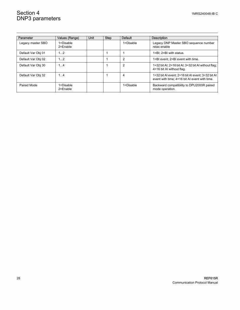
Parameter Values (Range) Unit Step Default DescriptionLegacy master SBO 1=Disable
2=Enable 1=Disable Legacy DNP Master SBO sequence number
relax enable
Default Var Obj 01 1...2 1 1 1=BI; 2=BI with status.
Default Var Obj 02 1...2 1 2 1=BI event; 2=BI event with time.
Default Var Obj 30 1...4 1 2 1=32 bit AI; 2=16 bit AI; 3=32 bit AI without flag;4=16 bit AI without flag.
Default Var Obj 32 1...4 1 4 1=32 bit AI event; 2=16 bit AI event; 3=32 bit AIevent with time; 4=16 bit AI event with time.
Paired Mode 1=Disable2=Enable
1=Disable Backward compatibility to DPU2000R pairedmode operation.
Section 4 1MRS240048-IB CDNP3 parameters
28 REF615RCommunication Protocol Manual

Section 5 Tolerances
5.1 DNP3 timing considerations
Table 12: The protection relay's worst-case error over the full operating temperature range
Description ValueTime base drift over a 10-minute interval 1.2 ms
Maximum delay measurement error ±15 ms
Maximum internal time reference error when set fromthe protocol
±100 ms
Maximum response time 50 ms turnaround time (TCP/IP)
Event time accuracy 4 ms for BI and 500 ms for AI
Event processing delay 20 ms for BI; 1500 ms for AI 1)
1) This represents the time it takes for a physical input from the time it changes to the time it is reported byDNP3. The internal latency between the protection logic and the communication processor is 4 ms for BI,and 500 ms for AI.
Data link layer filtering is not performed based on the source address.
The protection relay supports collision avoidance. Collision detection is available asimplemented by the DNP3 link layer and TCP/IP. When DNP3 uses the serial channel,there is no collision avoidance. Collision detection in this instance is handled by the DNP3link layer.
1MRS240048-IB C Section 5Tolerances
REF615R 29Communication Protocol Manual

30

Section 6 Glossary
615 series Series of numerical protection and control relays for protectionand supervision applications of utility substations, and industrialswitchgear and equipment
ABI Accepted but ignoredAI Analog inputANSI American National Standards InstituteBI Binary inputBOS Binary output statusCRC Cyclical redundancy checkCROB Control relay output blockData set The content basis for reporting and logging containing
references to the data and data attribute valuesDFC Data flow controlDNP3 A distributed network protocol originally developed by
Westronic. The DNP3 Users Group has the ownership of theprotocol and assumes responsibility for its evolution.
EMC Electromagnetic compatibilityEPA Enhanced performance architectureEthernet A standard for connecting a family of frame-based computer
networking technologies into a LANFCB 1. Flow control bit
2. Frame count bitHMI Human-machine interfaceIEC International Electrotechnical CommissionIEC 60870-5 IEC standard for telecontrol equipment and systems. Part 5
defines transmission protocols.IEC 61850 International standard for substation communication and
modelingIEC 61850-8-1 A communication protocol based on the IEC 61850 standard
series
1MRS240048-IB C Section 6Glossary
REF615R 31Communication Protocol Manual

IED Intelligent electronic deviceIIN Internal indication (DNP3)ISO International Standard OrganizationLHMI Local human-machine interfaceModbus A serial communication protocol developed by the Modicon
company in 1979. Originally used for communication in PLCsand RTU devices.
OSI Open systems interconnectionPCM600 Protection and Control IED ManagerRTU Remote terminal unitSDU Service data unitTCP/IP Transmission Control Protocol/Internet ProtocolUL Underwriters LaboratoriesUR Unsolicited responseWHMI Web human-machine interface
Section 6 1MRS240048-IB CGlossary
32 REF615RCommunication Protocol Manual

33

ABB Distribution SolutionsDistribution AutomationP.O. Box 699FI-65101 VAASA, FinlandPhone +358 10 22 11
ABB Inc.655 Century PointLake Mary, FL 32746, USAPhone +1-800-222 1946
www.abb.com/mediumvoltagewww.abb.com/relionwww.abb.com/substationautomation
—
© Copyright 2019 ABB. All rights reserved. 1MR
S24
00
48-
IB C