Embed Size (px)
Citation preview
DMG ECOLINE GMBHOberes Ried 11, A-6833 KlausTel. +43 [0] 55 23 / 90 601-600, Fax +43 [0] 55 23 / 90 601-650
PLANNING DOCUMENTS
Documents for the planning department on preparatory measures for theinstallation, commissioning and operation.
20 30 40
90
100
50 70
DMU 50 ECOLINE
COPYRIGHT This document is intended for the operating, mainte-nance and assembly staff. It is not admissible to pass on or to duplicate this document partly or in whole, to use or to communicate its contents. Exceptions must granted expressly. DMG ECOLINE reserve all rights for a possible patent grant or a possible pattern registration.
Non-compliances oblige to compensation for damage and can have penal consequences.
The publisher retains all rights, also the right to reprint, duplicate parts of the present manual and of the translation.
Without the written permission of the publisher, no part of the manual may be reproduced or may be copied in any form with the aid of electronic duplication systems, not even for instruction and training purposes.
The language acquisition of the manufacturer (German) prevails for the technical content.
Issue: V4711-V1
Ident no.: PU-EN
© 2004 DMG ECOLINE GmbH
1
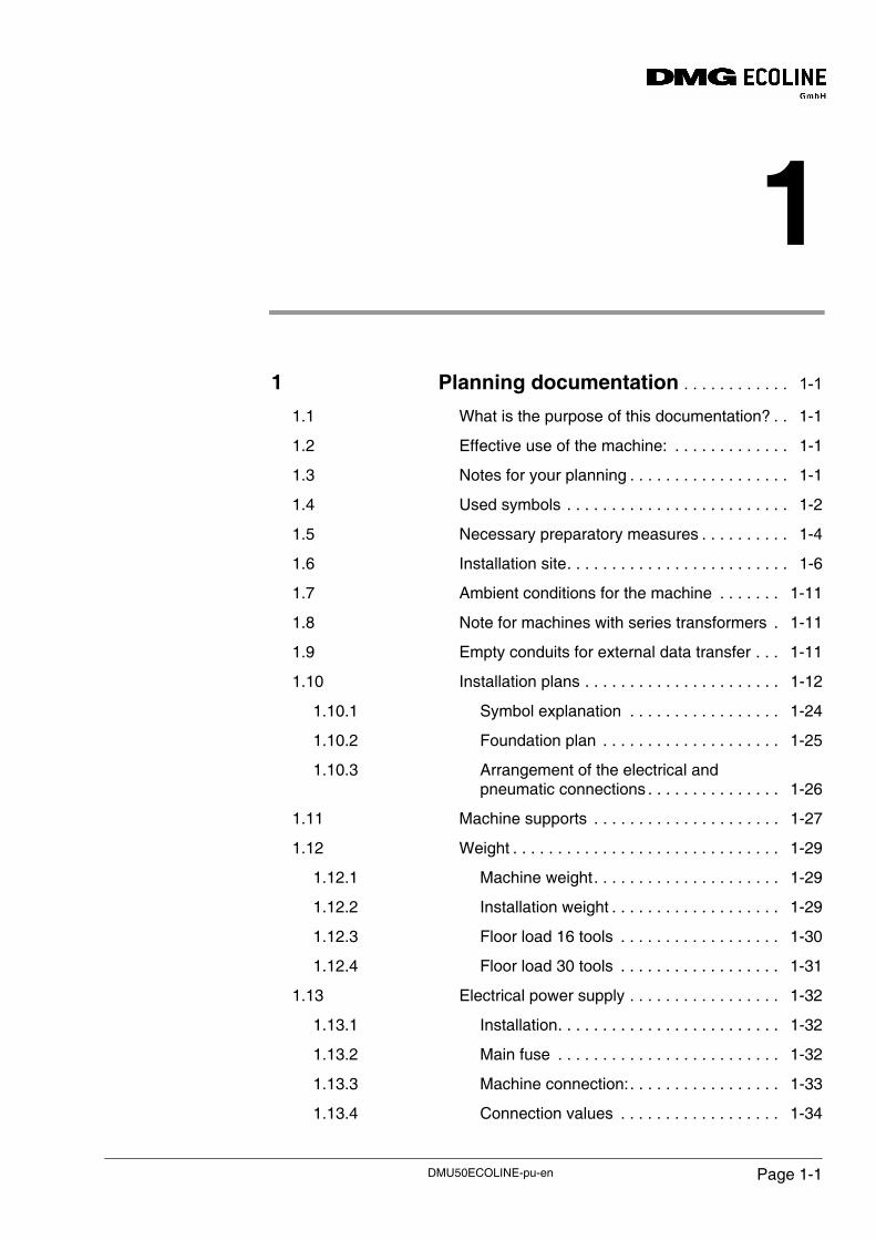
1 Planning documentation . . . . . . . . . . . . 1-11.1 What is the purpose of this documentation? . . 1-1
1.2 Effective use of the machine: . . . . . . . . . . . . . 1-1
1.3 Notes for your planning . . . . . . . . . . . . . . . . . . 1-1
1.4 Used symbols . . . . . . . . . . . . . . . . . . . . . . . . . 1-2
1.5 Necessary preparatory measures . . . . . . . . . . 1-4
1.6 Installation site. . . . . . . . . . . . . . . . . . . . . . . . . 1-6
1.7 Ambient conditions for the machine . . . . . . . 1-11
1.8 Note for machines with series transformers . 1-11
1.9 Empty conduits for external data transfer . . . 1-11
1.10 Installation plans . . . . . . . . . . . . . . . . . . . . . . 1-12
1.10.1 Symbol explanation . . . . . . . . . . . . . . . . . 1-24
1.10.2 Foundation plan . . . . . . . . . . . . . . . . . . . . 1-25
1.10.3 Arrangement of the electrical and pneumatic connections . . . . . . . . . . . . . . . 1-26
1.11 Machine supports . . . . . . . . . . . . . . . . . . . . . 1-27
1.12 Weight . . . . . . . . . . . . . . . . . . . . . . . . . . . . . . 1-29
1.12.1 Machine weight. . . . . . . . . . . . . . . . . . . . . 1-29
1.12.2 Installation weight . . . . . . . . . . . . . . . . . . . 1-29
1.12.3 Floor load 16 tools . . . . . . . . . . . . . . . . . . 1-30
1.12.4 Floor load 30 tools . . . . . . . . . . . . . . . . . . 1-31
1.13 Electrical power supply . . . . . . . . . . . . . . . . . 1-32
1.13.1 Installation. . . . . . . . . . . . . . . . . . . . . . . . . 1-32
1.13.2 Main fuse . . . . . . . . . . . . . . . . . . . . . . . . . 1-32
1.13.3 Machine connection:. . . . . . . . . . . . . . . . . 1-33
1.13.4 Connection values . . . . . . . . . . . . . . . . . . 1-34
DMU50ECOLINE-pu-en Page 1-1
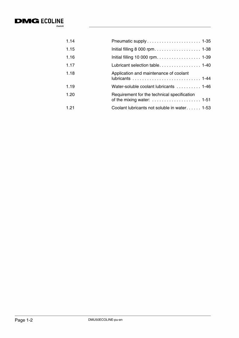
1.14 Pneumatic supply . . . . . . . . . . . . . . . . . . . . . . 1-35
1.15 Initial filling 8 000 rpm. . . . . . . . . . . . . . . . . . . 1-38
1.16 Initial filling 10 000 rpm. . . . . . . . . . . . . . . . . . 1-39
1.17 Lubricant selection table. . . . . . . . . . . . . . . . . 1-40
1.18 Application and maintenance of coolant lubricants . . . . . . . . . . . . . . . . . . . . . . . . . . . . 1-44
1.19 Water-soluble coolant lubricants . . . . . . . . . . 1-46
1.20 Requirement for the technical specification of the mixing water: . . . . . . . . . . . . . . . . . . . . 1-51
1.21 Coolant lubricants not soluble in water. . . . . . 1-53
DMU50ECOLINE-pu-enPage 1-2
Planning documentation
1 Planning documentation
1.1 What is the purpose of this documentation?
Basics
This documentation is aimed at the people responsible for installing the machine and their staff. This documentation contains all the information necessary for the preparation of the machine's installation site and its surroundings such that the machine can be installed immediately after delivery. Information on the transport of the machine to the installation site is also included.
Please also note the information on the tools and lubricants necessary, as well as on the tool mountings and retention bolts necessary for operation.
Commissioning
The machine is only allowed to be commissioned by a person authorised by the machine manufacturer. Otherwise, DMG ECOLINE will accept no liability whatsoever for any damage or malfunctions that may occur.
1.2 Effective use of the machine:
Training courses
DMG ECOLINE offers the training and the further training of experts as a service of our training academy. Whether the machine's features are actually used depends on the user's qualifications. For this reason, clarify in good time whether your staff has the necessary knowledge. Plan your training course dates so that all training measures are completed before the delivery of the machine.
1.3 Notes for your planning
Planning
The floor area figures stated in this documentation only apply to machines with the peripherals shown.
For information of the floor area and space requirements for the options you have ordered, please refer to the related installation plans.
The machine documentation applies irrespective of the specifications made in this documentation .
DMU50ECOLINE-pu-en Page 1-1
Planning documentation
1.4 Used symbols
Note
Special information on operating processes, machine reactions and economic use of the machine.
Figure 1-1
• Please pay attention to the related information.
• Also pass on all notes to other operators.
Attention
Special notes, requirements and prohibitions on the prevention of damages.
Figure 1-2
• Please pay attention to the related information.
• Also pass on all warnings and safety instructions to other operators.
Danger
Information, actions that must be performed and actions that are not allowed to prevent injury and extensive damage.
Figure 1-3
• Please pay attention to the related information.
• Take particular care in these cases to prevent accidents.
• Also pass on all safety instructions to other operators.
ATTENTION!
DANGER!
DMU50ECOLINE-pu-enPage 1-2
Planning documentation
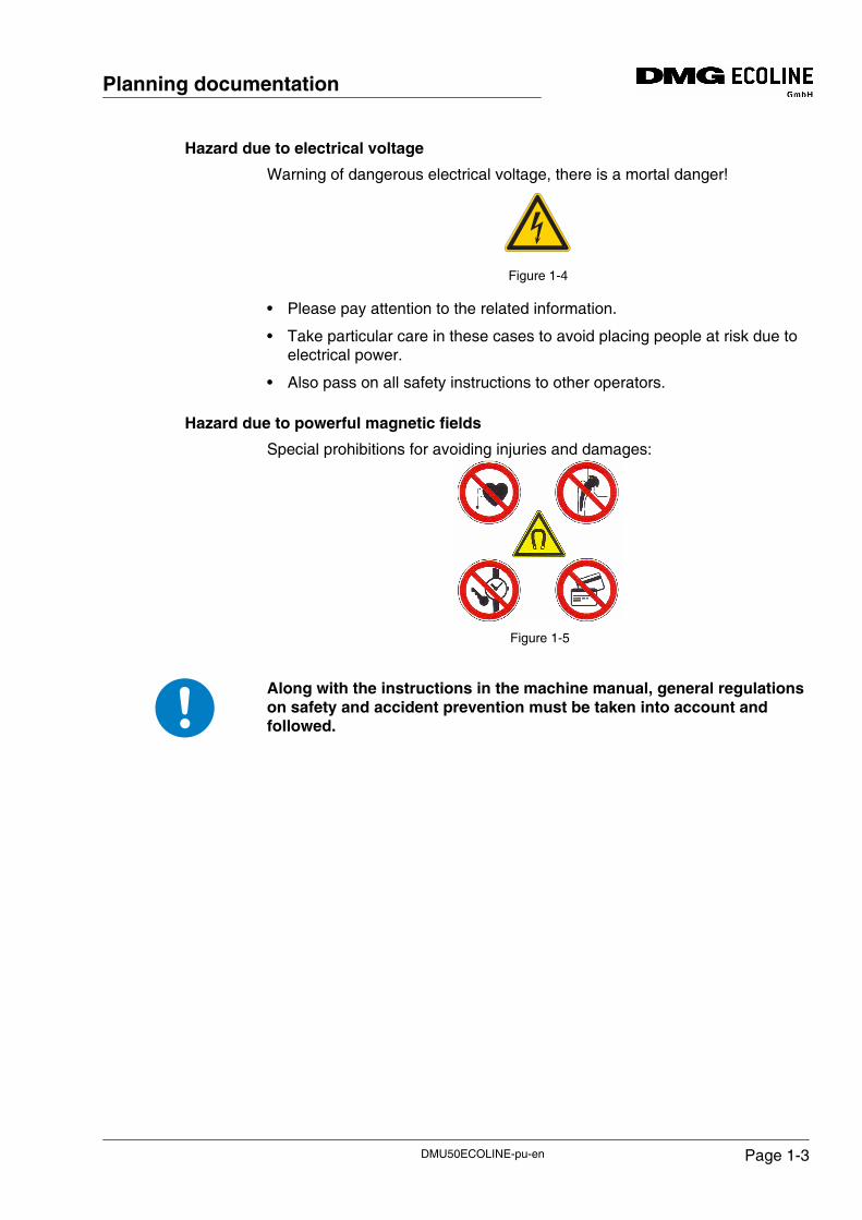
Hazard due to electrical voltage
Warning of dangerous electrical voltage, there is a mortal danger!
Figure 1-4
• Please pay attention to the related information.
• Take particular care in these cases to avoid placing people at risk due to electrical power.
• Also pass on all safety instructions to other operators.
Hazard due to powerful magnetic fields
Special prohibitions for avoiding injuries and damages:
Figure 1-5
Along with the instructions in the machine manual, general regulations on safety and accident prevention must be taken into account and followed.
DMU50ECOLINE-pu-en Page 1-3
Planning documentation
1.5 Necessary preparatory measures
Actions to be undertaken by the customer
The customer is responsible for the following preparatory measures:
Installation site
• Prepare the installation site of the machine
- see "Installation site"
• Ensuring the availability of:
- Supply of electricity, light, water, telephone
Transport
• Arrangement of unloading of the machine
• In-house transport to the installation site and installation of the machine
- The machine is to be transported to the installation site
- The machine is to be placed onto the levelling elements
E/P connection
• Connection of the machine
- Machine must be connected electrically ("CW rotating field").
- The machine must not be connected to a power supply with a residual-current circuit breaker. (Permanent connection necessary)
- Upon delivery to countries with large voltage fluctuations in the supply line of the system, a power supply stabilizer must be used in order to protect the electronic components.
- The machine must be connected to the compressed air supply
Commissioning
• Preparation for commissioning
- Preparation of the necessary lubricating oils / coolant lubricants
- Clean machine (degreasing)
- The temperature at the installation site must be controlled to a constant value.
- Align machine: +/- 0.1 mm/m
- Provide suitable assistants during commissioning
Tools
• A tool holder with appropriate retention bolts must be available
DMU50ECOLINE-pu-enPage 1-4
Planning documentation
Service / Maintenance
"In accordance with, respectively in amendment to the General installation conditions VDW 502 A and LMW 188 A, the customer is obliged to provide technical support during the installation and repair works, in particular by providing suitable and necessary platform ladders, installation platforms, scaffolds, transport equipment, heavy tools, lifting devices, etc."
The main switch of the machine may only be switched on in the presence of the authorized service staff member!
DANGER!
DMU50ECOLINE-pu-en Page 1-5
Planning documentation
1.6 Installation site
Customer information
It is imperative that this information is checked, safeguarded and implemented by the customer prior to the delivery of the machine.
The customer remains responsible for the correct location of the machine. The customer is fully responsible for an appropriate installation site.
If problems should occur later on that have been caused by a non-observance of the notes, DMG ECOLINE cannot be held responsible.
Ambient temperature
A fully air conditioned room fulfils all of these conditions.
• Constant room temperature of +/- 1°C. (Not a certain value, like e.g. 20 °C)
• It is very important that the temperature is the same in all machine points.
Wear reduction
In order to reduce the wear, there must be no machines in the same room which produce dusty machining residues:
Figure 1-6
• Also prevent grinding or erosion dust from entering the machine via workpieces and coolant lubricant.
ATTENTION!
DMU50ECOLINE-pu-enPage 1-6
Planning documentation
Corrosion prevention
In order to prevent corrosion at workpiece and machine, the installation site must be dry and free of aggressive vapours:
Figure 1-7
• No soldering, welding, varnishing, pickling or electroplating systems in the same room.
Foundation
An appropriate bottom plate that has been approved by the structural analyst (engineer engaged in statical calculation) is necessary.
Figure 1-8
• The bottom plate must not have any expansion joints in the area covered by the machine.
• Cracks, cable ducts or other interruptions are not allowed in the area covered by the machine.
• Place the machine onto a firm ground that makes sure that the machine is stable
• The machine must constantly be levelled in order to guarantee the accuracy of the machine.
• The floor must not be elastic so that the machine stays aligned precisely.
• The installation area must be free of oil and grease so that the coefficient of friction of the installation elements is not reduced.
• The ground must be firm and resistant against all liquids used at the machine in accordance with the locally valid environmental regulations.
DMU50ECOLINE-pu-en Page 1-7
Planning documentation
Load bearing capacity
Ensure a sufficient load bearing capacity of the floor:
Figure 1-9
• Have the load bearing capacity checked by a structural analyst (engineer engaged in statical calculations).
Have the structural engineer determine in a binding manner
• that the floor, basement floor, intermediate floor or substructure has the required load bearing capacity (especially in old buildings),
• that the installation site is in conformity with applicable building regulations.
Centre of gravity
Please note that the centre of gravity is shifted due to the workpiece weight and to the traversing paths.
Maximum weight
For the floor load bearing capacity, take into account
Figure 1-10
• the maximum installation weight of the machine and additionally the maximum weight of tool and accessory cabinets including contents,
- workpieces and devices,
- people,
- transport means,
- other devices in the immediate vicinity of the machine.
kg
ATTENTION!
kg k k k
DMU50ECOLINE-pu-enPage 1-8
Planning documentation
Basement floors, intermediate floors
When installing the machine on basement floors, intermediate floors or on other load-bearing structures:
Figure 1-11
Ask a structural analyst experienced in structural dynamics (engineer engaged in statical calculations) to certify in writing according to DIN 4024 Part 1: flexible structures that support machines with rotating elements,
• that the supporting structure is capable of bearing the effects of the forces of gravity of the machine,
• or, if this certification cannot be provided, that the measures for vibration damping that are then to be arranged are adequate.
Floor vibrations
Figure 1-12
Floor vibrations or shocks caused by adjacent machines or other producers must not affect the function and accuracy of the machine.
For absorbing vibrations, it generally suffices to place the machine onto vibration insulating plates. If necessary, an isolated foundation must be provided.
Figure 1-13
DMU50ECOLINE-pu-en Page 1-9
Planning documentation
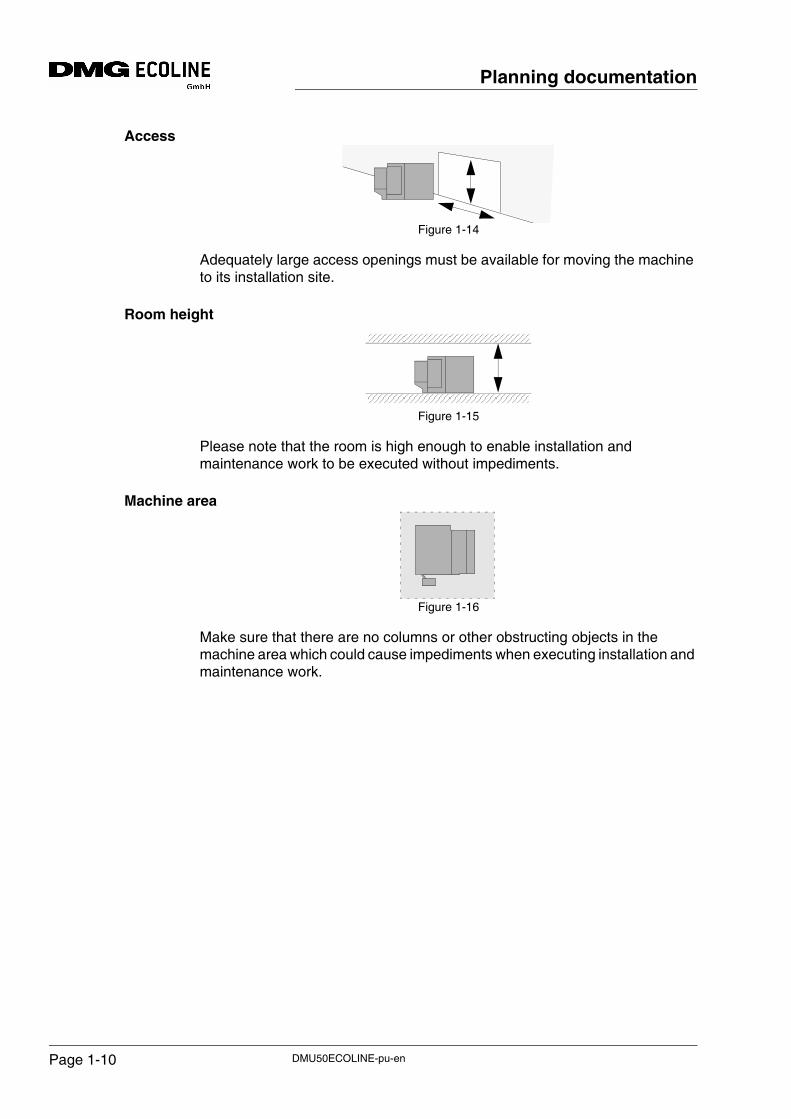
Access
Figure 1-14
Adequately large access openings must be available for moving the machine to its installation site.
Room height
Figure 1-15
Please note that the room is high enough to enable installation and maintenance work to be executed without impediments.
Machine area
Figure 1-16
Make sure that there are no columns or other obstructing objects in the machine area which could cause impediments when executing installation and maintenance work.
DMU50ECOLINE-pu-enPage 1-10
Planning documentation
1.7 Ambient conditions for the machineA fully air conditioned room fulfils all of these conditions.
• Constant room temperature of +/- 1°C.
(not a specific value, like e.g. 20 °C)
It is very important that the temperature is the same in all machine points.
• Permissible ambient temperature: +15° to + 35° C
• Maximum relative air humidity: 80 %
• Maximum installation altitude: 1000 m above sea level
If one of these values is exceeded at the installation site of the machine or in case of special operational conditions, e.g.
• action of powerful electric or magnetic fields
• installation in potentially explosive atmospheres or areas containing potentially explosive substances
contact your DMG ECOLINE (DMG) representative.
1.8 Note for machines with series transformersThe cable connection between the overcurrent protection device (main fuse) and the separate series transformer depends on the operating voltage at the customer. Appropriate protection against short circuits is to be provided by the customer.
The cable for the connection between the series transformer and the machine is part of our scope of delivery (in accordance with the installation site in the installation plan).
1.9 Empty conduits for external data transferIf external data transfer is planned, appropriate empty conduits made of metal must be installed for the data cable.
Data cables must not be laid alongside cables carrying high currents or cross such cables.
DMU50ECOLINE-pu-en Page 1-11
Planning documentation
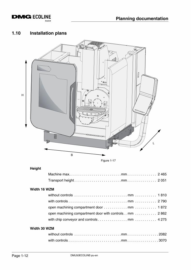
1.10 Installation plans
Figure 1-17
Height
Machine max. . . . . . . . . . . . . . . . . . . . . . . . . . .mm . . . . . . . . . . . . . . . 2 465
Transport height . . . . . . . . . . . . . . . . . . . . . . . .mm . . . . . . . . . . . . . . . 2 051
Width 16 WZM
without controls . . . . . . . . . . . . . . . . . . . . . . . . . . . mm . . . . . . . . . . . 1 810
with controls . . . . . . . . . . . . . . . . . . . . . . . . . . . . . . mm . . . . . . . . . . . 2 790
open machining compartment door . . . . . . . . . . . . mm . . . . . . . . . . . 1 872
open machining compartment door with controls. . mm . . . . . . . . . . . 2 862
with chip conveyor and controls . . . . . . . . . . . . . . . mm . . . . . . . . . . . 4 275
Width 30 WZM
without controls . . . . . . . . . . . . . . . . . . . . . . . .mm . . . . . . . . . . . . . . . . 2082
with controls . . . . . . . . . . . . . . . . . . . . . . . . . . .mm . . . . . . . . . . . . . . . . 3070
H
B
L
DMU50ECOLINE-pu-enPage 1-12
Planning documentation
with chip conveyor and controls . . . . . . . . . . . mm . . . . . . . . . . . . . . . 4 275
Length 16 / 30 WZM
without grip . . . . . . . . . . . . . . . . . . . . . . . . . . . mm . . . . . . . . . . . . . . . 2 125
with grip. . . . . . . . . . . . . . . . . . . . . . . . . . . . . . mm . . . . . . . . . . . . . . . 2 200
with controls . . . . . . . . . . . . . . . . . . . . . . . . . . mm . . . . . . . . . . . . . . . 2 720
Installation area L x W
with 16 WZM KSB . . . . . . . . . . . . . . . . . . . . . mm . . . . . . . . .4 630 x 3 990
with 16 WZM, SPF . . . . . . . . . . . . . . . . . . . . . mm . . . . . . . . .4 630 x 5 470
with 30 WZM, KSB . . . . . . . . . . . . . . . . . . . . . mm . . . . . . . . .4 630 x 4 270
with 30 WZM, SPF . . . . . . . . . . . . . . . . . . . . . mm . . . . . . . . .4 630 x 5 470
WZM = tool magazine
Moreover, the escape routes and the safety areas must be observed in accordance with local regulations, laws and instructions.
ATTENTION!
DMU50ECOLINE-pu-en Page 1-13
Planning documentation
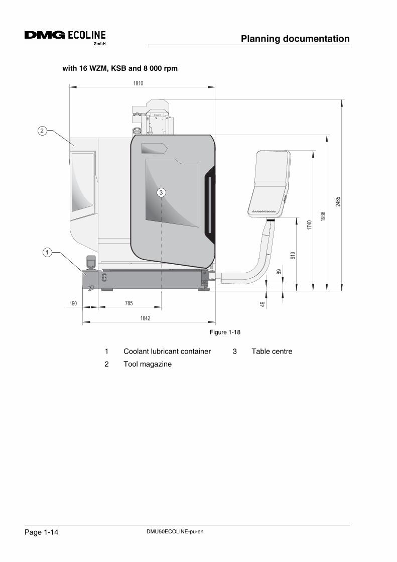
with 16 WZM, KSB and 8 000 rpm
Figure 1-18
1810
1642
785190 49
89
910
1740 19
36
2465
1
2
3
1 Coolant lubricant container
2 Tool magazine
3 Table centre
DMU50ECOLINE-pu-enPage 1-14
Planning documentation
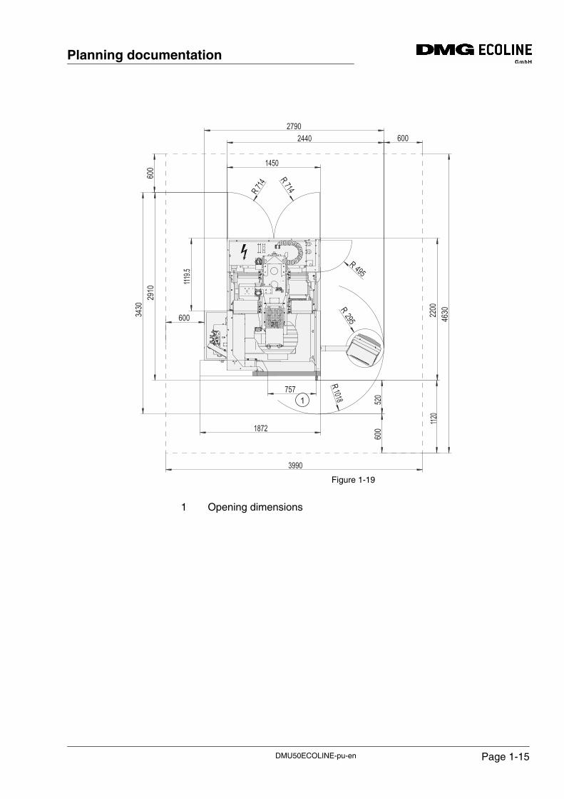
Figure 1-19
60024402790
600
2910
3430
600
R1018
R295
R 495R714R 7
14
1450
600
3990
1120
2200
4630
520
1119.5
757
1872
11
1 Opening dimensions
DMU50ECOLINE-pu-en Page 1-15
Planning documentation
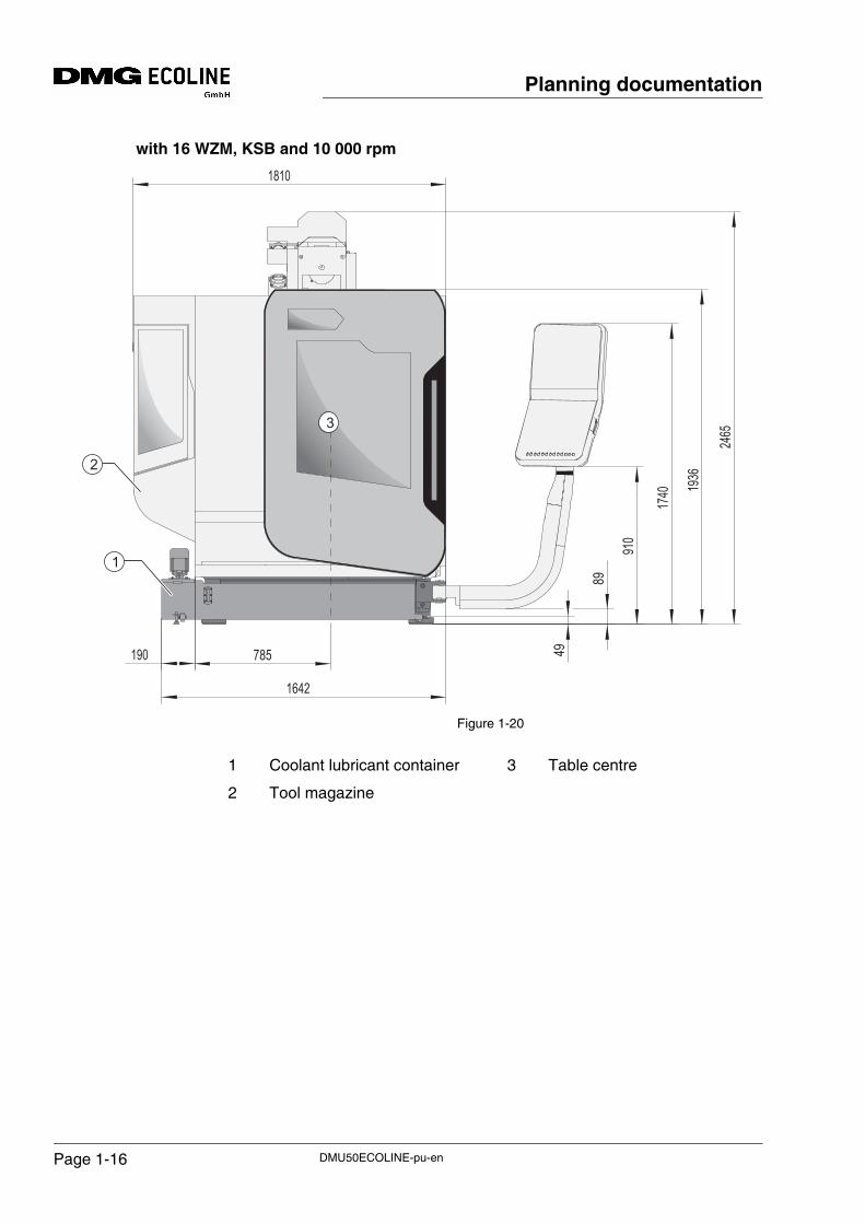
with 16 WZM, KSB and 10 000 rpm
Figure 1-20
1810
89
49
910
1740 19
36
2465
785190
1642
1
2
3
1 Coolant lubricant container
2 Tool magazine
3 Table centre
DMU50ECOLINE-pu-enPage 1-16
Planning documentation
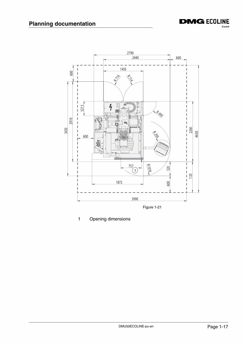
Figure 1-21
60024402790
R 714
R 714
145060
029
1034
30
600
R1018R 295
R 495
600
3990
1120
2200
4630
520
527.5
757
1872
11
1 Opening dimensions
DMU50ECOLINE-pu-en Page 1-17
Planning documentation
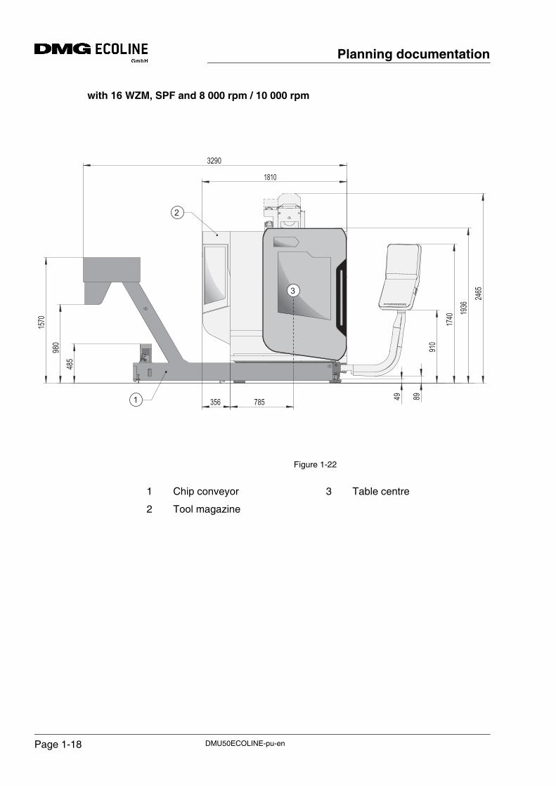
with 16 WZM, SPF and 8 000 rpm / 10 000 rpm
Figure 1-22
49 89
910
1740 19
36
2465
485980
1570
785
1810
3290
3561
2
3
1 Chip conveyor
2 Tool magazine
3 Table centre
DMU50ECOLINE-pu-enPage 1-18
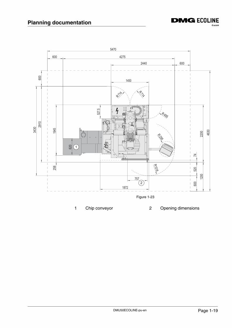
Planning documentation
Figure 1-23
R714
R714
R 495
R295
R10181450
2440 600
1872
600
2910
4275
527.5
757
600
3430
5470
4630
520
600
2200
74
1200
620
1945
258
1
12
1 Chip conveyor 2 Opening dimensions
DMU50ECOLINE-pu-en Page 1-19
Planning documentation
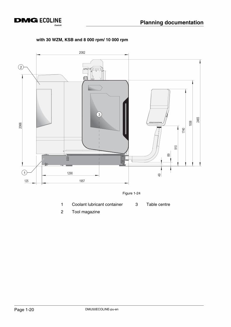
with 30 WZM, KSB and 8 000 rpm/ 10 000 rpm
Figure 1-24
2082
1290
125
89
49
910
1740
1936 2465
2066
1957
2
1
3
1 Coolant lubricant container
2 Tool magazine
3 Table centre
DMU50ECOLINE-pu-enPage 1-20
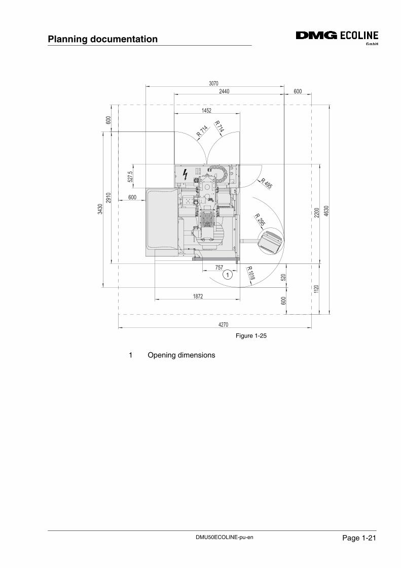
Planning documentation
Figure 1-25
60024403070
1452
R 714
R 714
600
2910
3430
600
R1018
600
1120
42702200 4630
R295
R 495
520
527.5
757
1872
11
1 Opening dimensions
DMU50ECOLINE-pu-en Page 1-21
Planning documentation
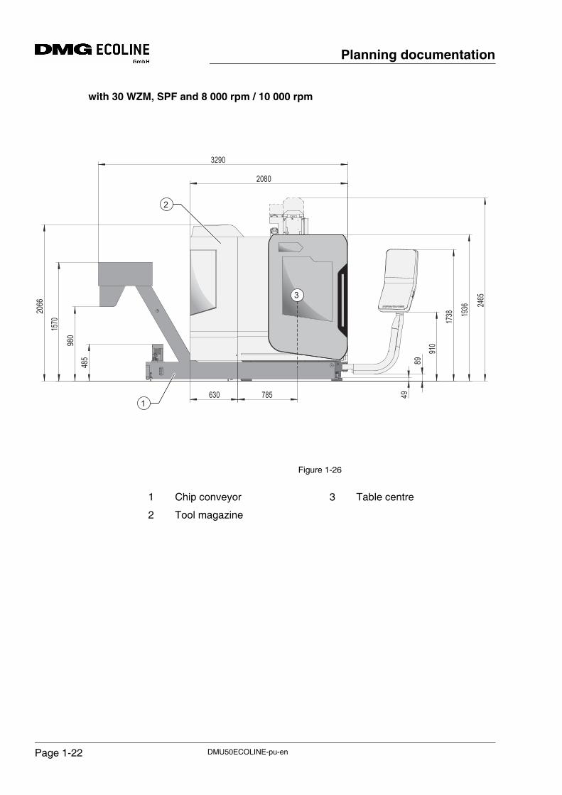
with 30 WZM, SPF and 8 000 rpm / 10 000 rpm
Figure 1-26
4989
910
1738 1936 24
65
2080
485
980
1570
2066
785630
3290
1
2
3
1 Chip conveyor
2 Tool magazine
3 Table centre
DMU50ECOLINE-pu-enPage 1-22
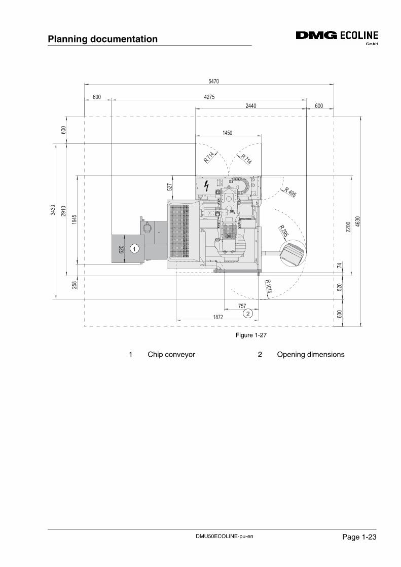
Planning documentation
Figure 1-27
R 714 R 714
R 495
R295
R1018
2440
1450
600
520
600
4275
2200
74
4630
3430
757
1872
258
620
527
600
2910
1945
5470
600
1
12
1 Chip conveyor 2 Opening dimensions
DMU50ECOLINE-pu-en Page 1-23
Planning documentation
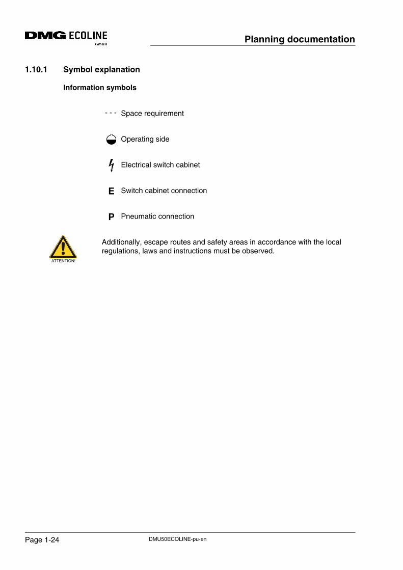
1.10.1 Symbol explanation
Information symbols
Space requirement
Operating side
Electrical switch cabinet
Switch cabinet connection
Pneumatic connection
Additionally, escape routes and safety areas in accordance with the local regulations, laws and instructions must be observed.
- - -
E
P
ATTENTION!
DMU50ECOLINE-pu-enPage 1-24
Planning documentation
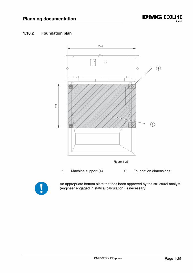
1.10.2 Foundation plan
Figure 1-28
An appropriate bottom plate that has been approved by the structural analyst (engineer engaged in statical calculation) is necessary.
1344
878
2
1
1 Machine support (4) 2 Foundation dimensions
DMU50ECOLINE-pu-en Page 1-25
Planning documentation
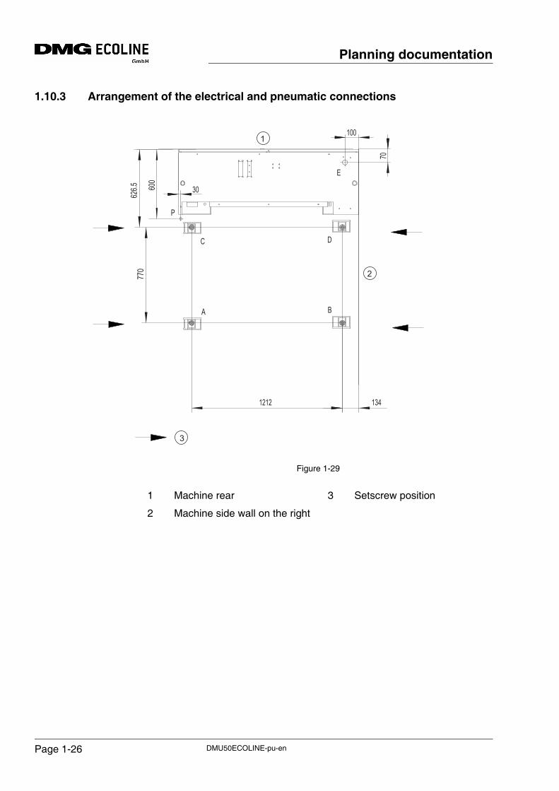
1.10.3 Arrangement of the electrical and pneumatic connections
Figure 1-29
E
P
C D
BA
626.5 600
770
1212 134
100
70
30
1
3
2
1 Machine rear
2 Machine side wall on the right
3 Setscrew position
DMU50ECOLINE-pu-enPage 1-26
Planning documentation
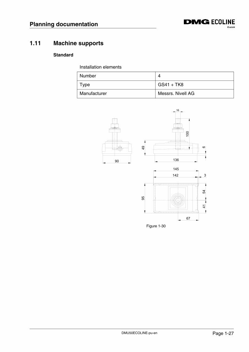
1.11 Machine supports
Standard
Figure 1-30
Installation elements
Number 4
Type GS41 + TK8
Manufacturer Messrs. Nivell AG
4995
90
142
145
54
3
67
41
100
136
16
6
DMU50ECOLINE-pu-en Page 1-27
Planning documentation
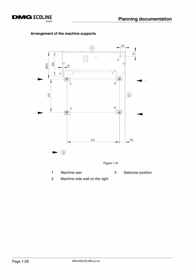
Arrangement of the machine supports
Figure 1-31
E
P
C D
BA
626.5 600
770
1212 134
100
70
30
1
3
2
1 Machine rear
2 Machine side wall on the right
3 Setscrew position
DMU50ECOLINE-pu-enPage 1-28
Planning documentation
1.12 Weight
1.12.1 Machine weightMachine with 16 WZM. . . . . . . . . . . . . . . . . . . approx. kg . . . . . . . . . . 3 960
Machine with 30 WZM. . . . . . . . . . . . . . . . . . . approx. kg . . . . . . . . . . 4 660
1.12.2 Installation weightMachine with max. weight for workpiece, tool and consumables, coolant lubricant system
Load upon the machine foot . . . . . . . . . . . . . . . . . . . . see machine support
WZM = tool magazine
DMU50ECOLINE-pu-en Page 1-29
Planning documentation
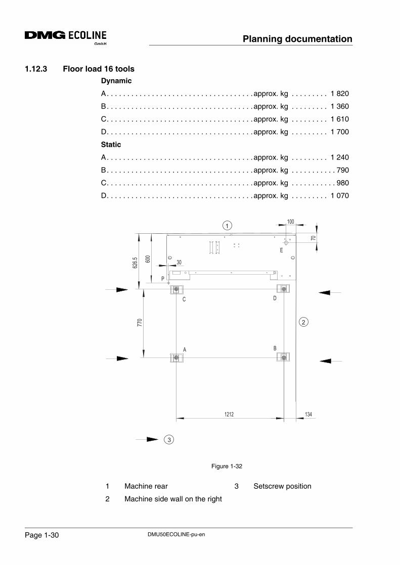
1.12.3 Floor load 16 toolsDynamic
A. . . . . . . . . . . . . . . . . . . . . . . . . . . . . . . . . . . . approx. kg . . . . . . . . . 1 820
B. . . . . . . . . . . . . . . . . . . . . . . . . . . . . . . . . . . . approx. kg . . . . . . . . . 1 360
C. . . . . . . . . . . . . . . . . . . . . . . . . . . . . . . . . . . . approx. kg . . . . . . . . . 1 610
D. . . . . . . . . . . . . . . . . . . . . . . . . . . . . . . . . . . . approx. kg . . . . . . . . . 1 700
Static
A. . . . . . . . . . . . . . . . . . . . . . . . . . . . . . . . . . . . approx. kg . . . . . . . . . 1 240
B. . . . . . . . . . . . . . . . . . . . . . . . . . . . . . . . . . . . approx. kg . . . . . . . . . . . 790
C. . . . . . . . . . . . . . . . . . . . . . . . . . . . . . . . . . . . approx. kg . . . . . . . . . . . 980
D. . . . . . . . . . . . . . . . . . . . . . . . . . . . . . . . . . . . approx. kg . . . . . . . . . 1 070
Figure 1-32
E
P
C D
BA
626.5 600
770
1212 134
100
70
30
1
3
2
1 Machine rear
2 Machine side wall on the right
3 Setscrew position
DMU50ECOLINE-pu-enPage 1-30
Planning documentation
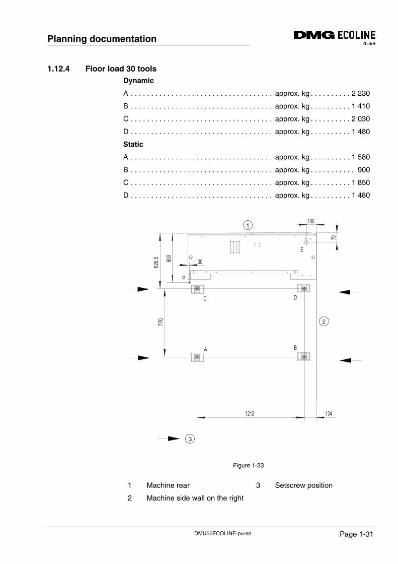
1.12.4 Floor load 30 toolsDynamic
A . . . . . . . . . . . . . . . . . . . . . . . . . . . . . . . . . . . approx. kg . . . . . . . . . . 2 230
B . . . . . . . . . . . . . . . . . . . . . . . . . . . . . . . . . . . approx. kg . . . . . . . . . . 1 410
C . . . . . . . . . . . . . . . . . . . . . . . . . . . . . . . . . . . approx. kg . . . . . . . . . . 2 030
D . . . . . . . . . . . . . . . . . . . . . . . . . . . . . . . . . . . approx. kg . . . . . . . . . . 1 480
Static
A . . . . . . . . . . . . . . . . . . . . . . . . . . . . . . . . . . . approx. kg . . . . . . . . . . 1 580
B . . . . . . . . . . . . . . . . . . . . . . . . . . . . . . . . . . . approx. kg . . . . . . . . . . . 900
C . . . . . . . . . . . . . . . . . . . . . . . . . . . . . . . . . . . approx. kg . . . . . . . . . . 1 850
D . . . . . . . . . . . . . . . . . . . . . . . . . . . . . . . . . . . approx. kg . . . . . . . . . . 1 480
Figure 1-33
E
P
C D
BA
626.5 600
770
1212 134
100
70
30
1
3
2
1 Machine rear
2 Machine side wall on the right
3 Setscrew position
DMU50ECOLINE-pu-en Page 1-31
Planning documentation
1.13 Electrical power supply
1.13.1 InstallationDuring the electrical installation, attention is to be paid to ensuring EN 60 204, part 1, point 6.3.3 "Protection by automatic interruption of the power supply" is met.
On this topic, also see IEC 364-4-41 (DIN 57 100, VDE 0100, part 410).
The machine must not be connected to a power supply with a residual-current circuit breaker. See EN 50 178, section 5.3.2.3.
As our machine has a leakage current higher than 3.5 mA AC due to EMC measures, it must have a fixed connection.
Furthermore, one of the measures specified below must be executed according to EN 50178, section 5.3.2.1.
• Cross section of the protective earth conductor at least 10 mm2 Cu (see "Electrical data").
• This also applies to special systems that may have been connected directly to the customer's power supply and that have not been routed across the machine.
or
• Monitoring of the protective earth conductor by a device that will automatically shut down the electronic equipment in the event of a fault.
or
• Laying of a second conductor, electrically in parallel with the protective earth conductor, using separate terminals. This conductor must fulfil the requirements for protective conductors on its own according to section 543 of the harmonization document (HD) 384.5.54 S1 (old DIN VDE 0100 part 540) for protective earth conductors.
If the supply voltage is a TN-S power supply and if the 400 VAC operating voltage is within the tolerances ± 10%, i.e. 360 VAC to 440 VAC, the machine may be connected directly.
If the supply voltage is a TN-S power supply and if the operating voltage is not within the limits of 360 VAC to 440 VAC, the machine requires a pre-disconnecting transformer.
1.13.2 Main fuseThe overcurrent protection (main fuse) for the mains connection cable must have been installed outside of the machine and is not part of the scope of delivery of DMG ECOLINE.
DMU50ECOLINE-pu-enPage 1-32
Planning documentation
1.13.3 Machine connection:The power supply for connecting the machine or parts of the machine must be a TN-S power supply with 3 conductors (L1, L2, L3) and a neutral conductor (N) as well as a protective earth conductor (PE).
Power supply. . . . . . . . 3 phases (L1, L2, L3), neutral conductor and protective conductor, 50/60 Hz, 400/230 VAC with tolerance ± 10%
The actual mains voltage is not allowed to vary from the rated voltage by more than the permitted tolerance, even under load.
Cross section of the connection cable according to DIN 57100 / VDE 0100 or other locally valid standards!
Risk of accident due to electrical voltage!
• The electrical connection is only allowed to be made by an electrician.
• Observe primarily the locally valid regulations and directives.
When working on electrical equipment, damages may occur at electronic components due to incorrect or faulty connections. Always observe the specifications in the wiring diagrams.
Supply cable, fuse protection
Power supply and fuse protection are to be designed as per the information on the type plate for the switch cabinet.
ATTENTION!
ATTENTION!
DMU50ECOLINE-pu-en Page 1-33
Planning documentation
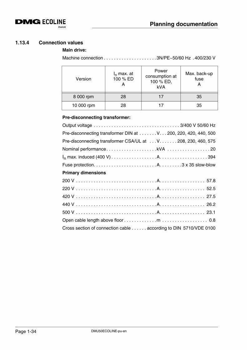
1.13.4 Connection valuesMain drive:
Machine connection . . . . . . . . . . . . . . . . . . . . . 3N/PE~50/60 Hz .400/230 V
Pre-disconnecting transformer:
Output voltage . . . . . . . . . . . . . . . . . . . . . . . . . . . . . . . . . . 3/400 V 50/60 Hz
Pre-disconnecting transformer DIN at . . . . . . .V. . . 200, 220, 420, 440, 500
Pre-disconnecting transformer CSA/UL at . . .V. . . . . . . 208, 230, 460, 575
Nominal performance. . . . . . . . . . . . . . . . . . . . kVA . . . . . . . . . . . . . . . . . 20
In max. induced (400 V) . . . . . . . . . . . . . . . . . .A. . . . . . . . . . . . . . . . . . . 394
Fuse protection. . . . . . . . . . . . . . . . . . . . . . . . .A. . . . . . . . .3 x 35 slow-blow
Primary dimensions
200 V . . . . . . . . . . . . . . . . . . . . . . . . . . . . . . . .A. . . . . . . . . . . . . . . . . . 57.8
220 V . . . . . . . . . . . . . . . . . . . . . . . . . . . . . . . .A. . . . . . . . . . . . . . . . . . 52.5
420 V . . . . . . . . . . . . . . . . . . . . . . . . . . . . . . . .A. . . . . . . . . . . . . . . . . . 27.5
440 V . . . . . . . . . . . . . . . . . . . . . . . . . . . . . . . .A. . . . . . . . . . . . . . . . . . 26.2
500 V . . . . . . . . . . . . . . . . . . . . . . . . . . . . . . . .A. . . . . . . . . . . . . . . . . . 23.1
Open cable length above floor . . . . . . . . . . . . .m . . . . . . . . . . . . . . . . . . 0.8
Cross section of connection cable . . . . . . according to DIN 5710/VDE 0100
VersionIn max. at 100 % ED
A
Power consumption at
100 % ED, kVA
Max. back-up fuse
A
8 000 rpm 28 17 35
10 000 rpm 28 17 35
DMU50ECOLINE-pu-enPage 1-34
Planning documentation
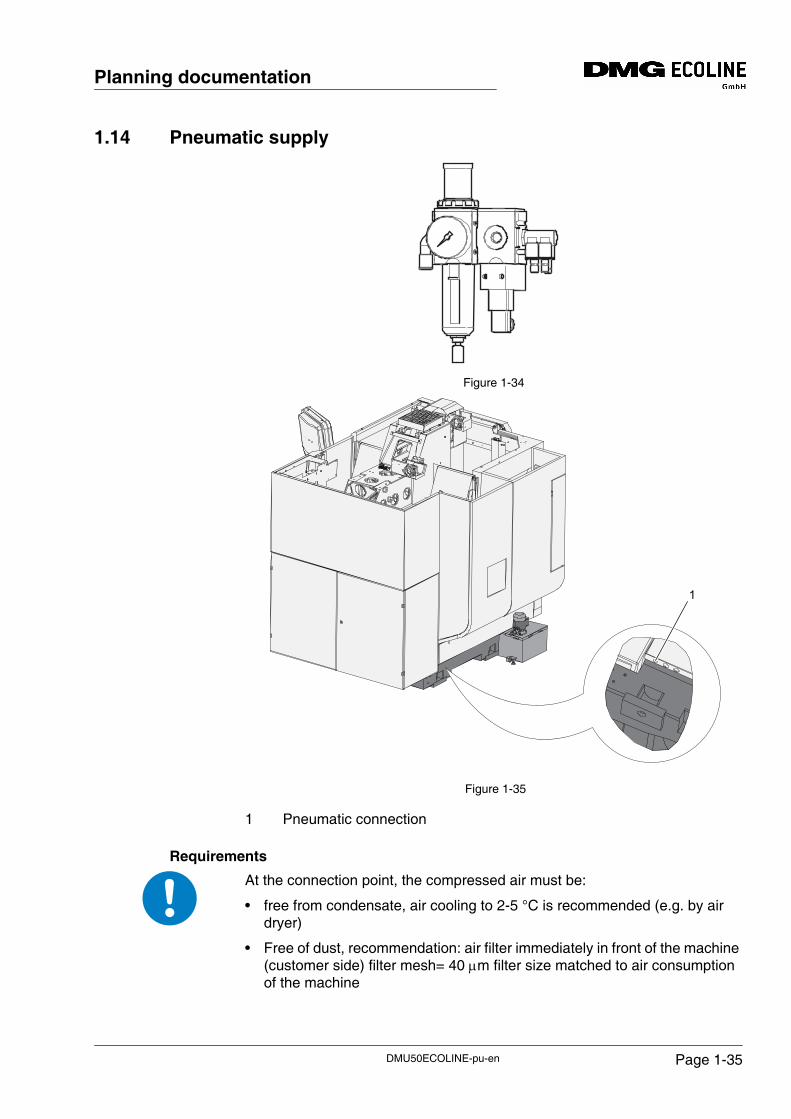
1.14 Pneumatic supply
Figure 1-34
Figure 1-35
1 Pneumatic connection
Requirements
At the connection point, the compressed air must be:
• free from condensate, air cooling to 2-5 °C is recommended (e.g. by air dryer)
• Free of dust, recommendation: air filter immediately in front of the machine (customer side) filter mesh= 40 μm filter size matched to air consumption of the machine
1
DMU50ECOLINE-pu-en Page 1-35
Planning documentation
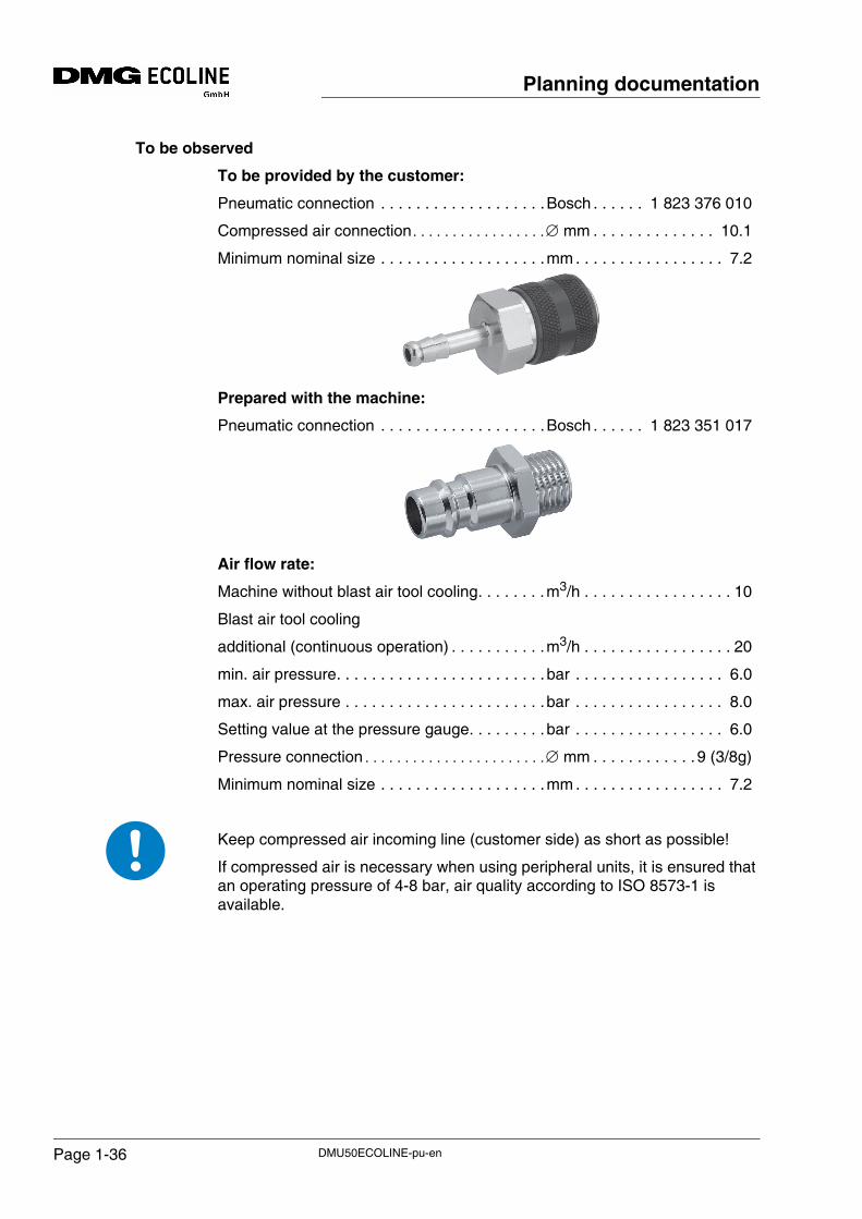
To be observed
To be provided by the customer:
Pneumatic connection . . . . . . . . . . . . . . . . . . .Bosch . . . . . . 1 823 376 010
Compressed air connection . . . . . . . . . . . . . . . . .∅ mm . . . . . . . . . . . . . . 10.1
Minimum nominal size . . . . . . . . . . . . . . . . . . .mm . . . . . . . . . . . . . . . . . 7.2
Prepared with the machine:
Pneumatic connection . . . . . . . . . . . . . . . . . . .Bosch . . . . . . 1 823 351 017
Air flow rate:
Machine without blast air tool cooling. . . . . . . .m3/h . . . . . . . . . . . . . . . . . 10
Blast air tool cooling
additional (continuous operation) . . . . . . . . . . .m3/h . . . . . . . . . . . . . . . . . 20
min. air pressure. . . . . . . . . . . . . . . . . . . . . . . . bar . . . . . . . . . . . . . . . . . 6.0
max. air pressure . . . . . . . . . . . . . . . . . . . . . . .bar . . . . . . . . . . . . . . . . . 8.0
Setting value at the pressure gauge. . . . . . . . . bar . . . . . . . . . . . . . . . . . 6.0
Pressure connection . . . . . . . . . . . . . . . . . . . . . . .∅ mm . . . . . . . . . . . . 9 (3/8g)
Minimum nominal size . . . . . . . . . . . . . . . . . . .mm . . . . . . . . . . . . . . . . . 7.2
Keep compressed air incoming line (customer side) as short as possible!
If compressed air is necessary when using peripheral units, it is ensured that an operating pressure of 4-8 bar, air quality according to ISO 8573-1 is available.
DMU50ECOLINE-pu-enPage 1-36
Planning documentation
Solid matters / particle size
Quality class 5. . . . . . . . . . . . . . . . . . . . . . . . . µg . . . . . . . . . . . . . . . . . < 40
Water / Pressure dew point
Quality class 4. . . . . . . . . . . . . . . . . . . . . . . . . °C . . . . . . . . . . . . . . . . . < +3
Oil / Residual oil content
Quality class 2. . . . . . . . . . . . . . . . . . . . . . . . . mg/m3 . . . . . . . . . . . . . < 0.1
Volume (V) . . . . . . . . . . . . . . . . . . . . . . . . . . . m3/min. . . . . . . . . . . . . . . . 3
DMU50ECOLINE-pu-en Page 1-37
Planning documentation
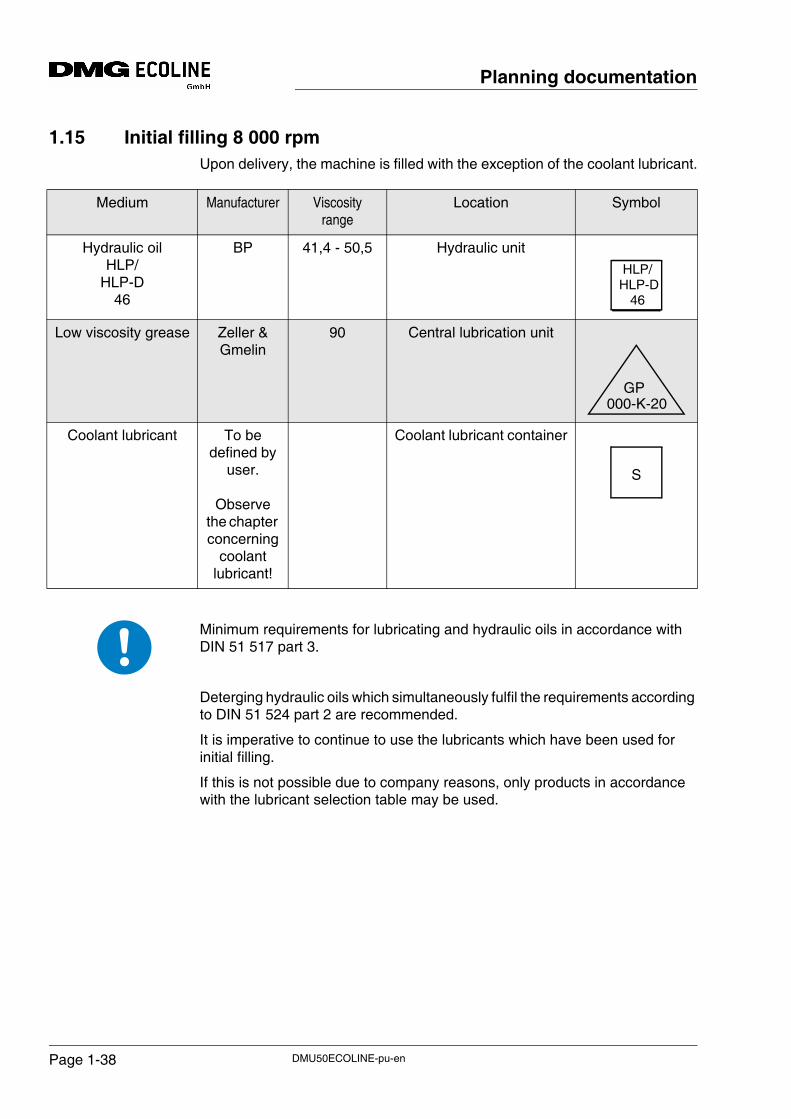
1.15 Initial filling 8 000 rpmUpon delivery, the machine is filled with the exception of the coolant lubricant.
Minimum requirements for lubricating and hydraulic oils in accordance with DIN 51 517 part 3.
Deterging hydraulic oils which simultaneously fulfil the requirements according to DIN 51 524 part 2 are recommended.
It is imperative to continue to use the lubricants which have been used for initial filling.
If this is not possible due to company reasons, only products in accordance with the lubricant selection table may be used.
Medium Manufacturer Viscosity range
Location Symbol
Hydraulic oilHLP/
HLP-D 46
BP 41,4 - 50,5 Hydraulic unit
Low viscosity grease Zeller &Gmelin
90 Central lubrication unit
Coolant lubricant To be defined by
user.
Observe the chapter concerning
coolant lubricant!
Coolant lubricant container
HLP/HLP-D 46
GP000-K-20
S
DMU50ECOLINE-pu-enPage 1-38
Planning documentation
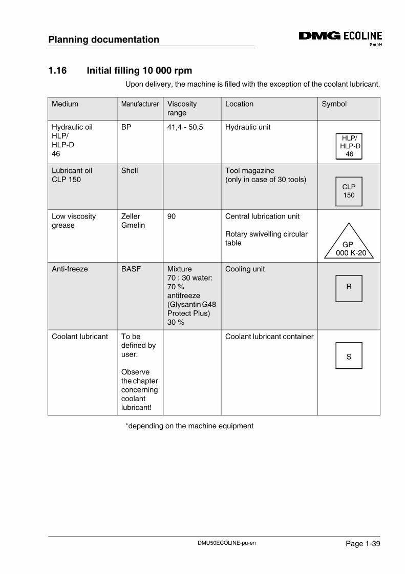
1.16 Initial filling 10 000 rpmUpon delivery, the machine is filled with the exception of the coolant lubricant.
*depending on the machine equipment
Medium Manufacturer Viscosity range
Location Symbol
Hydraulic oil HLP/HLP-D 46
BP 41,4 - 50,5 Hydraulic unit
Lubricant oil CLP 150
Shell Tool magazine(only in case of 30 tools)
Low viscosity grease
ZellerGmelin
90 Central lubrication unit
Rotary swivelling circular table
Anti-freeze BASF Mixture 70 : 30 water: 70 % antifreeze (Glysantin G48 Protect Plus) 30 %
Cooling unit
Coolant lubricant To be defined by user.
Observe the chapter concerning coolant lubricant!
Coolant lubricant container
HLP/HLP-D 46
CLP150
GP 000 K-20
R
S
DMU50ECOLINE-pu-en Page 1-39
Planning documentation
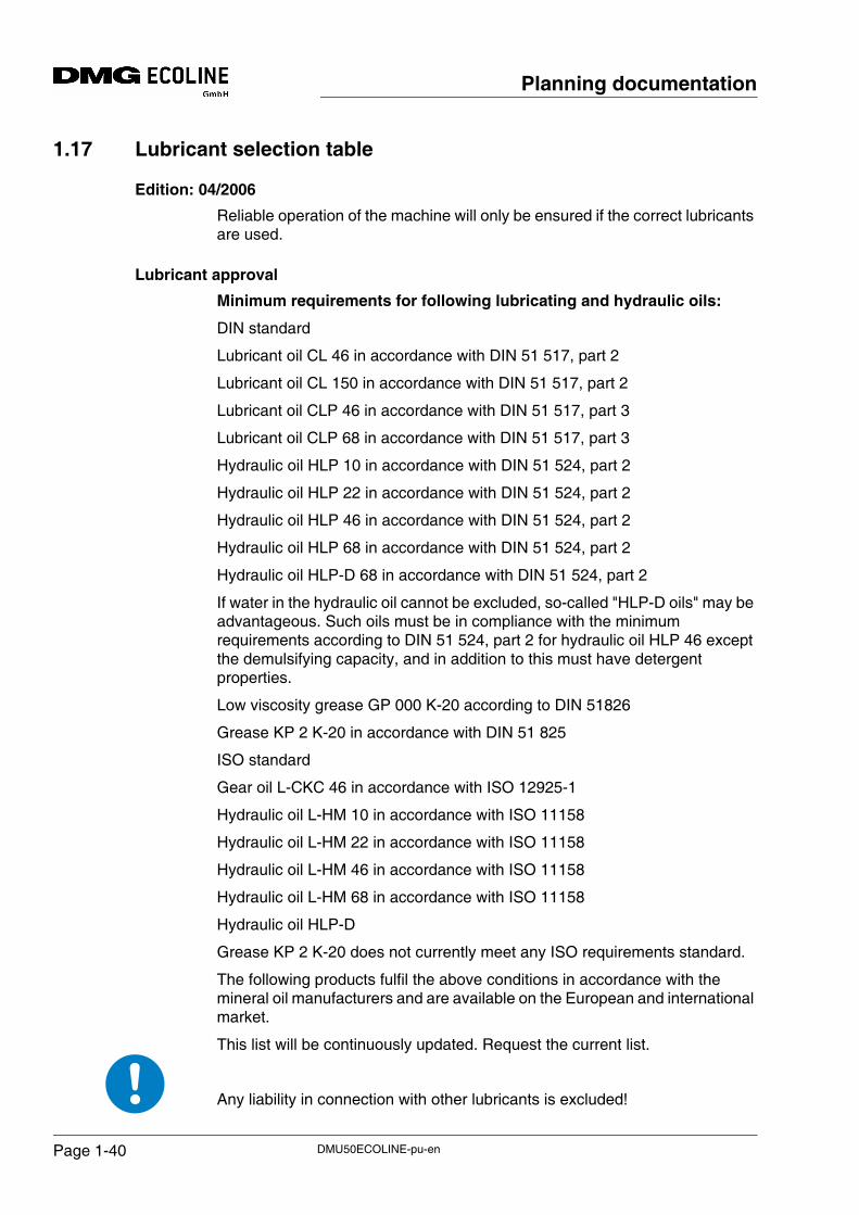
1.17 Lubricant selection table
Edition: 04/2006
Reliable operation of the machine will only be ensured if the correct lubricants are used.
Lubricant approval
Minimum requirements for following lubricating and hydraulic oils:
DIN standard
Lubricant oil CL 46 in accordance with DIN 51 517, part 2
Lubricant oil CL 150 in accordance with DIN 51 517, part 2
Lubricant oil CLP 46 in accordance with DIN 51 517, part 3
Lubricant oil CLP 68 in accordance with DIN 51 517, part 3
Hydraulic oil HLP 10 in accordance with DIN 51 524, part 2
Hydraulic oil HLP 22 in accordance with DIN 51 524, part 2
Hydraulic oil HLP 46 in accordance with DIN 51 524, part 2
Hydraulic oil HLP 68 in accordance with DIN 51 524, part 2
Hydraulic oil HLP-D 68 in accordance with DIN 51 524, part 2
If water in the hydraulic oil cannot be excluded, so-called "HLP-D oils" may be advantageous. Such oils must be in compliance with the minimum requirements according to DIN 51 524, part 2 for hydraulic oil HLP 46 except the demulsifying capacity, and in addition to this must have detergent properties.
Low viscosity grease GP 000 K-20 according to DIN 51826
Grease KP 2 K-20 in accordance with DIN 51 825
ISO standard
Gear oil L-CKC 46 in accordance with ISO 12925-1
Hydraulic oil L-HM 10 in accordance with ISO 11158
Hydraulic oil L-HM 22 in accordance with ISO 11158
Hydraulic oil L-HM 46 in accordance with ISO 11158
Hydraulic oil L-HM 68 in accordance with ISO 11158
Hydraulic oil HLP-D
Grease KP 2 K-20 does not currently meet any ISO requirements standard.
The following products fulfil the above conditions in accordance with the mineral oil manufacturers and are available on the European and international market.
This list will be continuously updated. Request the current list.
Any liability in connection with other lubricants is excluded!
DMU50ECOLINE-pu-enPage 1-40
Planning documentation
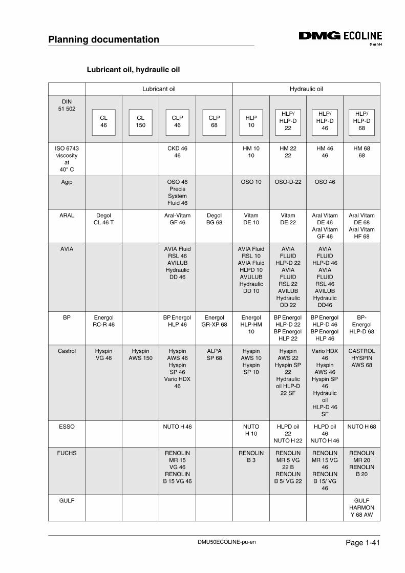
Lubricant oil, hydraulic oil
Lubricant oil Hydraulic oil
DIN 51 502
ISO 6743 viscosity
at 40° C
CKD 4646
HM 1010
HM 2222
HM 4646
HM 6868
Agip OSO 46 Precis
System Fluid 46
OSO 10 OSO-D-22 OSO 46
ARAL DegolCL 46 T
Aral-Vitam GF 46
DegolBG 68
Vitam DE 10
Vitam DE 22
Aral Vitam DE 46
Aral Vitam GF 46
Aral Vitam DE 68
Aral Vitam HF 68
AVIA AVIA FluidRSL 46 AVILUB
Hydraulic DD 46
AVIA Fluid RSL 10
AVIA FluidHLPD 10AVULUB Hydraulic
DD 10
AVIA FLUID
HLP-D 22AVIA
FLUID RSL 22AVILUB
Hydraulic DD 22
AVIA FLUID
HLP-D 46AVIA
FLUID RSL 46AVILUB
Hydraulic DD46
BP EnergolRC-R 46
BP Energol HLP 46
EnergolGR-XP 68
Energol HLP-HM
10
BP Energol HLP-D 22
BP Energol HLP 22
BP Energol HLP-D 46
BP Energol HLP 46
BP-Energol
HLP-D 68
Castrol HyspinVG 46
HyspinAWS 150
Hyspin AWS 46HyspinSP 46
Vario HDX 46
ALPASP 68
Hyspin AWS 10Hyspin SP 10
Hyspin AWS 22
Hyspin SP 22
Hydraulic oil HLP-D
22 SF
Vario HDX 46
Hyspin AWS 46
Hyspin SP 46
Hydraulic oil
HLP-D 46 SF
CASTROL HYSPIN AWS 68
ESSO NUTO H 46 NUTO H 10
HLPD oil 22
NUTO H 22
HLPD oil 46
NUTO H 46
NUTO H 68
FUCHS RENOLIN MR 15 VG 46
RENOLIN B 15 VG 46
RENOLIN B 3
RENOLIN MR 5 VG
22 B RENOLIN B 5/ VG 22
RENOLIN MR 15 VG
46 RENOLIN B 15/ VG
46
RENOLIN MR 20
RENOLIN B 20
GULF GULF HARMONY 68 AW
CL46
CL150
CLP46
CLP68
HLP10
HLP/HLP-D
22
HLP/HLP-D
46
HLP/HLP-D
68
DMU50ECOLINE-pu-en Page 1-41
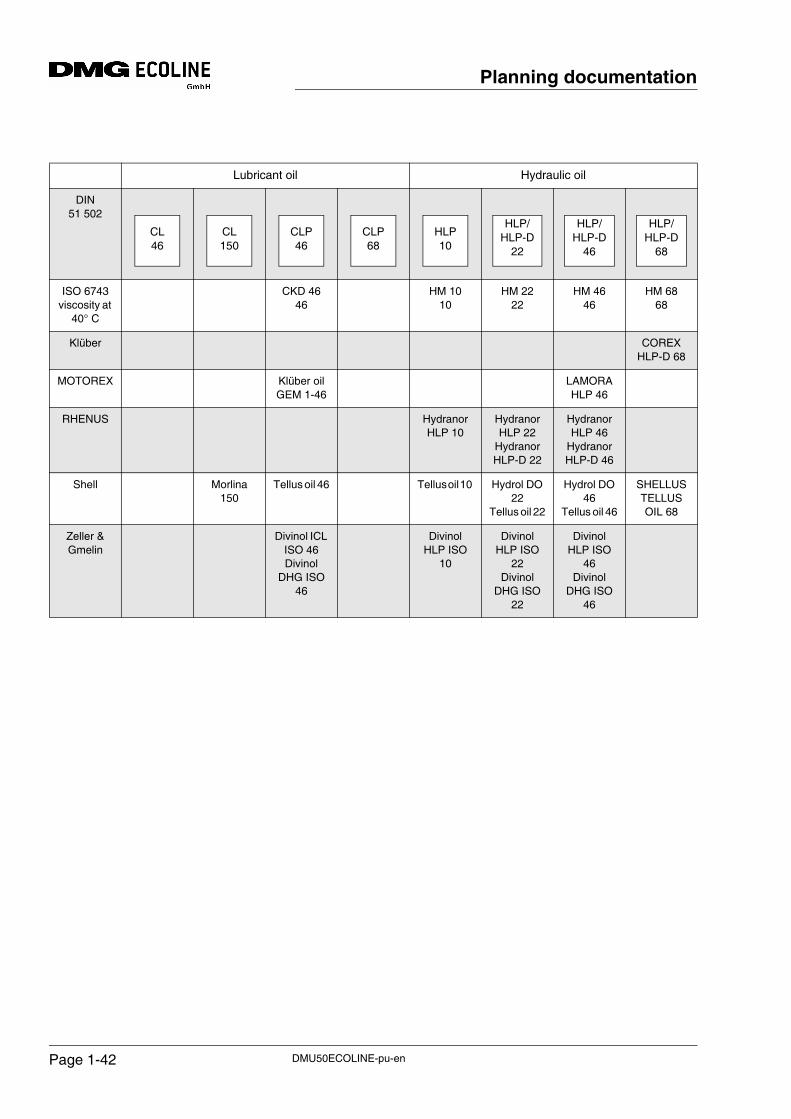
Planning documentation
Lubricant oil Hydraulic oil
DIN 51 502
ISO 6743 viscosity at
40° C
CKD 4646
HM 1010
HM 2222
HM 4646
HM 6868
Klüber COREX HLP-D 68
MOTOREX Klüber oil GEM 1-46
LAMORA HLP 46
RHENUS Hydranor HLP 10
Hydranor HLP 22
Hydranor HLP-D 22
Hydranor HLP 46
Hydranor HLP-D 46
Shell Morlina150
Tellus oil 46 Tellus oil 10 Hydrol DO 22
Tellus oil 22
Hydrol DO 46
Tellus oil 46
SHELLUS TELLUS OIL 68
Zeller & Gmelin
Divinol ICL ISO 46Divinol
DHG ISO 46
Divinol HLP ISO
10
Divinol HLP ISO
22Divinol
DHG ISO 22
Divinol HLP ISO
46Divinol
DHG ISO 46
CL46
CL150
CLP46
CLP68
HLP10
HLP/HLP-D
22
HLP/HLP-D
46
HLP/HLP-D
68
DMU50ECOLINE-pu-enPage 1-42
Planning documentation
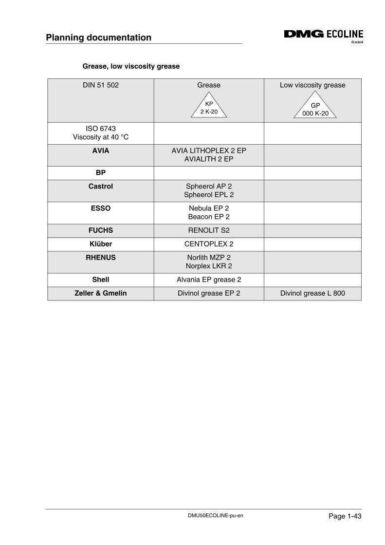
Grease, low viscosity grease
DIN 51 502 Grease Low viscosity grease
ISO 6743Viscosity at 40 °C
AVIA AVIA LITHOPLEX 2 EPAVIALITH 2 EP
BP
Castrol Spheerol AP 2Spheerol EPL 2
ESSO Nebula EP 2Beacon EP 2
FUCHS RENOLIT S2
Klüber CENTOPLEX 2
RHENUS Norlith MZP 2Norplex LKR 2
Shell Alvania EP grease 2
Zeller & Gmelin Divinol grease EP 2 Divinol grease L 800
KP2 K-20
GP000 K-20
DMU50ECOLINE-pu-en Page 1-43
Planning documentation
1.18 Application and maintenance of coolant lubricants
Increased danger of accidents when using oils and coolant lubricants! Protective goggles must be worn when working with oil or coolant lubricants.
General
Only the correct selection of suitable coolant lubricants as well as proper care and maintenance of the coolant lubricant will ensure that no problems arise.
In the following, some important aspects for the quality of manufacture and the ecology are listed:
• Mineral oil content
• Water polluting classes
• Additives
• Universal suitability for a wide range of machining tasks and materials
• Skin tolerance
These aspects are to be specified by the machine operator himself and lie within his scope of responsibility.
The selection of the coolant lubricants as well as their care is the task of the machine user. However, here the requirements placed by DMG ECOLINE GmbH must be met.
DANGER!
DMU50ECOLINE-pu-enPage 1-44
Planning documentation
For this reason, DMG ECOLINE GmbH cannot be held responsible for machine damage caused by the organisation operating the machine by
• the use of unsuitable coolant lubricants
• the lack of, or incorrect care and servicing of the coolant lubricant
• the use of unsuitable mixing water.
In case problems arise, please consult the supplier of your coolant lubricant (CL supplier). We would be pleased to provide assistance if you have any further questions.
Deliberately, specific products are not recommended; only information on chemical-physical and microbiological guidelines and properties is stated.
The coolant lubricant must be matched to the mixing water for the coolant lubricant emulsion and the machining tasks without fail.
In case of a written confirmation by your coolant lubricant supplier, that the coolant lubricant delivered by him fulfils the parameters (see "Requirements and specifications for the coolant lubricant used in the machine"), nothing speaks against its use in machines made by DMG ECOLINE.
In order to ensure a safe functioning of the machine/system, the water-soluble coolant lubricant must be inspected at least once per week (also in case of a machine standstill) as far as the concentration, the pH value, the bacteria and the attack by fungi are concerned (see "Requirements for the inspection and documentation of the coolant lubricant").
The proof for the adherence to the given limit values is given by tests listed in the guideline which are normally executed by your coolant lubricant supplier or by independent laboratories, if you do not have the necessary equipment yourself.
ATTENTION!
DMU50ECOLINE-pu-en Page 1-45
Planning documentation
1.19 Water-soluble coolant lubricants
Requirements and specifications for the coolant lubricant used in the machine
General
The coolant lubricants used must comply with the current regulations from the related authorities.
It must also be ensured that only those coolant lubricants are used which comply with the requirements listed in the table.
DMU50ECOLINE-pu-enPage 1-46
Planning documentation
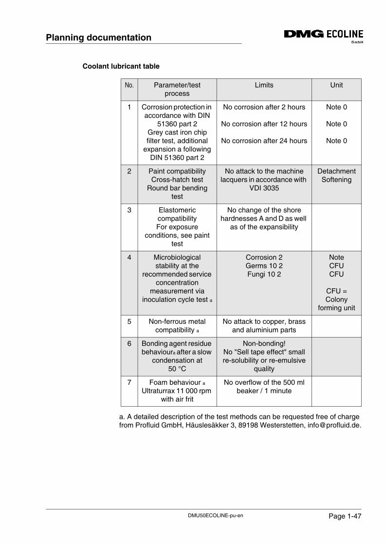
Coolant lubricant table
a. A detailed description of the test methods can be requested free of charge from Profluid GmbH, Häuslesäkker 3, 89198 Westerstetten, [email protected].
No. Parameter/test process
Limits Unit
1 Corrosion protection in accordance with DIN
51360 part 2Grey cast iron chip filter test, additional
expansion a following DIN 51360 part 2
No corrosion after 2 hours
No corrosion after 12 hours
No corrosion after 24 hours
Note 0
Note 0
Note 0
2 Paint compatibilityCross-hatch test
Round bar bending test
No attack to the machine lacquers in accordance with
VDI 3035
DetachmentSoftening
3 Elastomeric compatibilityFor exposure
conditions, see paint test
No change of the shore hardnesses A and D as well
as of the expansibility
4 Microbiological stability at the
recommended service concentration
measurement via inoculation cycle test a
Corrosion 2Germs 10 2Fungi 10 2
NoteCFUCFU
CFU = Colony
forming unit
5 Non-ferrous metal compatibility a
No attack to copper, brass and aluminium parts
6 Bonding agent residue behavioura after a slow
condensation at 50 °C
Non-bonding!No "Sell tape effect" small re-solubility or re-emulsive
quality
7 Foam behaviour aUltraturrax 11 000 rpm
with air frit
No overflow of the 500 ml beaker / 1 minute
DMU50ECOLINE-pu-en Page 1-47
Planning documentation
Explanations
About 1.) The inspection for corrosion protective measures is executed with the grey cast iron chip test in accordance with DIN 51360 part 2. The DIN method foresees a reading after one hour. However, at variance with this requirement, the filter papers are assessed after 1 hour and after 12 and 24 hours. The assessment scale is in accordance with DIN 51360 part 2.
About 2.) The coolant lubricant should not degrade the properties of the coating in the cross-hatch test in accordance with DIN EN ISO 2409 after soaking for 14 days at 50 °C. Also, the paint hardness in accordance with (EN ISO 2815) should not be degraded. In the round bar bending test (12 mm) on a coated 0.7 mm metal plate there should not be any cracking up to 45°.
About 3.) In accordance with DIN 53505, the values for Shore hardness A and D must remain unchanged, also the linear dimensions in accordance with DIN 53534.
About 4.) On machine tools with a dedicated coolant lubricant system, analyses, care and the addition of service chemicals are often uneconomical, for this reason the coolant lubricants must have suitable basic properties and stability for this type of machine from the start. A suitable coolant lubricant should demonstrate the necessary bio stability reserves in the inoculation cycle test.
DMU50ECOLINE-pu-enPage 1-48
Planning documentation
Abbreviated test description for inoculation cycle test:
Solutions or emulsions are prepared from the coolant lubricants to be tested using sterile standard water (20°dH). The mixtures are inoculated with reference germs once a week. By means of subsequent, weekly determination of the pH value, the corrosion protection properties (filter paper chip test) as well as the determination of the number of colonies, the limit for the micro bacterial load is determined. The following germs are used for this purpose:
Mixtures of bacteria:
• Pseudomonas aeroginosa (NCIB 6749)
• Shewanella putrifaciens (NCIB 12202)
• Citrobacter freundii (NCIB 12203)
• Alcaligenes faecali (NCIB 13104)
Mixtures of fungi:
• Fusarium solani
• Geotrichum candidum
About 5.) Qualitative evaluation of the non-ferrous metal corrosion with copper strips made of electrolytic copper.
DMU50ECOLINE-pu-en Page 1-49
Planning documentation
About 6.) During this test, 25 ml of the 5 % (percentage by weight) CL mixture is evaporated in a glass Petri dish with the water from the user. The bonding behaviour is stated as "honey-like" (draws thin threads), "thick" (paint-like film), "transparent adhesive tape" (bonds like transparent adhesive tape, contact surface similar to familiar adhesive tape). The bonding action should be as weak as possible. Please note that an excessively strong bonding action can have negative effects on the machine functions, particularly if the machine is not used for an extended period of time.
About 7.) The test is suitable for comparing the tendency to form foam and foam stability of coolant lubricants. In an extension, it is also possible to determine the "soda effect" (tendency to discharge due to bursting foam bubbles). Coolant lubricants and CL working solutions with inadequate foam properties can be detected more easily.
For this reason, the following general requirements apply to the coolant lubricant:
• They must be non-polluting and suitable for the workplace. Consequently they must be free of nitrites, PCB, chlorines and nitrosable diethanolamine (DEA) (as per TRGS 611).
• It should be possible to provide skin tolerance assessments.
• Mineral oil content in accordance with DIN 51417 at least. 40 % in the concentrate.
• As far as possible, they must be suitable for universal application for all machining tasks and materials.
• High cutting performance due to appropriate additives.
The coolant lubricant is not allowed to contain more than 15 % by volume of inflammable liquid (e.g. oil). Deflagration / danger of explosions!
When using coolant lubricants with an increased portion of combustible fluid, an additional "explosion protective package" machine is under all circumstances necessary (inquiry at DMG ECOLINE).
DMG ECOLINE does not assume any guarantee for follow-up damages, if inappropriate coolant lubricants are used!
DANGER!
ATTENTION!
DMU50ECOLINE-pu-enPage 1-50
Planning documentation
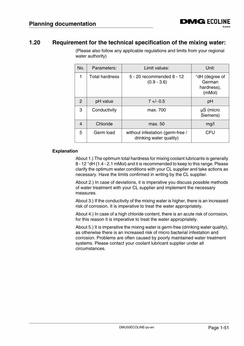
1.20 Requirement for the technical specification of the mixing water:(Please also follow any applicable regulations and limits from your regional water authority)
Explanation
About 1.) The optimum total hardness for mixing coolant lubricants is generally 8 - 12 °dH (1.4 - 2.1 mMol) and it is recommended to keep to this range. Please clarify the optimum water conditions with your CL supplier and take actions as necessary. Have the limits confirmed in writing by the CL supplier.
About 2.) In case of deviations, it is imperative you discuss possible methods of water treatment with your CL supplier and implement the necessary measures.
About 3.) If the conductivity of the mixing water is higher, there is an increased risk of corrosion. It is imperative to treat the water appropriately.
About 4.) In case of a high chloride content, there is an acute risk of corrosion, for this reason it is imperative to treat the water appropriately.
About 5.) It is imperative the mixing water is germ-free (drinking water quality), as otherwise there is an increased risk of micro bacterial infestation and corrosion. Problems are often caused by poorly maintained water treatment systems. Please contact your coolant lubricant supplier under all circumstances.
No. Parameters: Limit values: Unit:
1 Total hardness 5 - 20 recommended 8 - 12 (0.9 - 3.6)
°dH (degree of German
hardness), (mMol)
2 pH value 7 +/- 0.5 pH
3 Conductivity max. 700 µS (micro Siemens)
4 Chloride max. 50 mg/l
5 Germ load without infestation (germ-free / drinking water quality)
CFU
DMU50ECOLINE-pu-en Page 1-51
Planning documentation
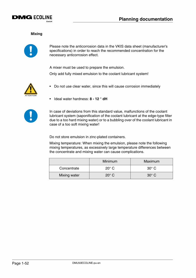
Mixing
Please note the anticorrosion data in the VKIS data sheet (manufacturer's specifications) in order to reach the recommended concentration for the necessary anticorrosion effect.
A mixer must be used to prepare the emulsion.
Only add fully mixed emulsion to the coolant lubricant system!
• Do not use clear water, since this will cause corrosion immediately
• Ideal water hardness: 8 - 12 ° dH
In case of deviations from this standard value, malfunctions of the coolant lubricant system (saponification of the coolant lubricant at the edge-type filter due to a too hard mixing water) or to a bubbling over of the coolant lubricant in case of a too soft mixing water!
Do not store emulsion in zinc-plated containers.
Mixing temperature: When mixing the emulsion, please note the following mixing temperatures, as excessively large temperature differences between the concentrate and mixing water can cause complications.
Minimum Maximum
Concentrate 20° C 30° C
Mixing water 20° C 30° C
ATTENTION!
DMU50ECOLINE-pu-enPage 1-52
Planning documentation
1.21 Coolant lubricants not soluble in water
Coolant lubricants (cutting oils etc.) with an oil content of >15 % may only be used in connection with a machine which has been equipped with an "explosion protection package"!
It is not admissible to use non-water-soluble coolant lubricants (cutting oils) due to safety reasons (danger of explosion).
High machining performance and the related higher tool speeds will result in heavy atomisation of the coolant lubricant that cannot be mixed with water.
There is the possibility of a deflagration or of an explosion.
Hazard due to deflagration
Deflagrations at the machine or in the machining environment may occur if the following conditions occur at the same time:
• In case of cutting operation including the grinding of metals at the machine.
• On the use of a coolant lubricant with more than 15 % by volume oils or concentrates (with flash point) or less than 85 % by volume water content.
• When splashing or atomizing coolant lubricants to a large extent with a concentration exceeding 10 g/m3
• The machine has a limited or enclosed chamber (machine housing, machine encapsulation) where an explosive mixture can build up.
Measures
When using non-water-soluble coolant lubricants, an additional "explosive protection package" is under all circumstances necessary. (Inquiry at DMG ECOLINE).
DDANGER!
DANGER!
ATTENTION!
DMU50ECOLINE-pu-en Page 1-53
Planning documentation
DMU50ECOLINE-pu-enPage 1-54