Embed Size (px)
Citation preview
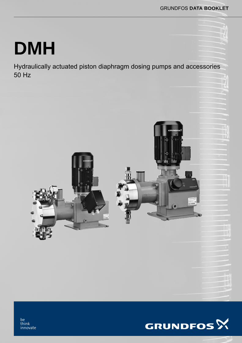
GRUNDFOS DATA BOOKLET
DMHHydraulically actuated piston diaphragm dosing pumps and accessories50 Hz
Ta
ble
of c
on
ten
ts
2
DMH
1. Product introduction 4Performance range . . . . . . . . . . . . . . . . . . . . . . . . . . . . . . . . . . . . . . . . . . . . . . . . . . . . . . . . . . . . . . . . . . . . . . . . . . . . 4Features and benefits . . . . . . . . . . . . . . . . . . . . . . . . . . . . . . . . . . . . . . . . . . . . . . . . . . . . . . . . . . . . . . . . . . . . . . . . . . 5
2. Identification 7Type key . . . . . . . . . . . . . . . . . . . . . . . . . . . . . . . . . . . . . . . . . . . . . . . . . . . . . . . . . . . . . . . . . . . . . . . . . . . . . . . . . . . . 7
3. Functions and options 9Capacity control . . . . . . . . . . . . . . . . . . . . . . . . . . . . . . . . . . . . . . . . . . . . . . . . . . . . . . . . . . . . . . . . . . . . . . . . . . . . . . . 9Electric servomotor . . . . . . . . . . . . . . . . . . . . . . . . . . . . . . . . . . . . . . . . . . . . . . . . . . . . . . . . . . . . . . . . . . . . . . . . . . . 11AR control unit . . . . . . . . . . . . . . . . . . . . . . . . . . . . . . . . . . . . . . . . . . . . . . . . . . . . . . . . . . . . . . . . . . . . . . . . . . . . . . . 11Stroke sensor. . . . . . . . . . . . . . . . . . . . . . . . . . . . . . . . . . . . . . . . . . . . . . . . . . . . . . . . . . . . . . . . . . . . . . . . . . . . . . . . 12AMS diaphragm protection system . . . . . . . . . . . . . . . . . . . . . . . . . . . . . . . . . . . . . . . . . . . . . . . . . . . . . . . . . . . . . . . 12Diaphragm leakage detection . . . . . . . . . . . . . . . . . . . . . . . . . . . . . . . . . . . . . . . . . . . . . . . . . . . . . . . . . . . . . . . . . . . 12Frequency converter (VFD) . . . . . . . . . . . . . . . . . . . . . . . . . . . . . . . . . . . . . . . . . . . . . . . . . . . . . . . . . . . . . . . . . . . . . 13Parameter box . . . . . . . . . . . . . . . . . . . . . . . . . . . . . . . . . . . . . . . . . . . . . . . . . . . . . . . . . . . . . . . . . . . . . . . . . . . . . . . 13
4. Construction 15General information . . . . . . . . . . . . . . . . . . . . . . . . . . . . . . . . . . . . . . . . . . . . . . . . . . . . . . . . . . . . . . . . . . . . . . . . . . . 15Sectional drawings. . . . . . . . . . . . . . . . . . . . . . . . . . . . . . . . . . . . . . . . . . . . . . . . . . . . . . . . . . . . . . . . . . . . . . . . . . . . 15
5. Technical data 20Dimensions . . . . . . . . . . . . . . . . . . . . . . . . . . . . . . . . . . . . . . . . . . . . . . . . . . . . . . . . . . . . . . . . . . . . . . . . . . . . . . . . . 20Weights . . . . . . . . . . . . . . . . . . . . . . . . . . . . . . . . . . . . . . . . . . . . . . . . . . . . . . . . . . . . . . . . . . . . . . . . . . . . . . . . . . . . 22Motor power . . . . . . . . . . . . . . . . . . . . . . . . . . . . . . . . . . . . . . . . . . . . . . . . . . . . . . . . . . . . . . . . . . . . . . . . . . . . . . . . . 22Flange sizes for pumps without motor . . . . . . . . . . . . . . . . . . . . . . . . . . . . . . . . . . . . . . . . . . . . . . . . . . . . . . . . . . . . . 22Pump protection class . . . . . . . . . . . . . . . . . . . . . . . . . . . . . . . . . . . . . . . . . . . . . . . . . . . . . . . . . . . . . . . . . . . . . . . . . 22Sound pressure . . . . . . . . . . . . . . . . . . . . . . . . . . . . . . . . . . . . . . . . . . . . . . . . . . . . . . . . . . . . . . . . . . . . . . . . . . . . . . 22Accuracy . . . . . . . . . . . . . . . . . . . . . . . . . . . . . . . . . . . . . . . . . . . . . . . . . . . . . . . . . . . . . . . . . . . . . . . . . . . . . . . . . . . 22Temperature of dosing medium . . . . . . . . . . . . . . . . . . . . . . . . . . . . . . . . . . . . . . . . . . . . . . . . . . . . . . . . . . . . . . . . . . 22
6. Pump selection 23Performance data . . . . . . . . . . . . . . . . . . . . . . . . . . . . . . . . . . . . . . . . . . . . . . . . . . . . . . . . . . . . . . . . . . . . . . . . . . . . 23Catalogue variants (selection) . . . . . . . . . . . . . . . . . . . . . . . . . . . . . . . . . . . . . . . . . . . . . . . . . . . . . . . . . . . . . . . . . . . 26Catalogue variants . . . . . . . . . . . . . . . . . . . . . . . . . . . . . . . . . . . . . . . . . . . . . . . . . . . . . . . . . . . . . . . . . . . . . . . . . . . . 29
7. Selection of accessories 34DMH models 251 to 257 . . . . . . . . . . . . . . . . . . . . . . . . . . . . . . . . . . . . . . . . . . . . . . . . . . . . . . . . . . . . . . . . . . . . . . . 34DMH models 280 to 288 . . . . . . . . . . . . . . . . . . . . . . . . . . . . . . . . . . . . . . . . . . . . . . . . . . . . . . . . . . . . . . . . . . . . . . . 34
8. Accessories for small dosing pumps 35Installation kits for dosing pumps. . . . . . . . . . . . . . . . . . . . . . . . . . . . . . . . . . . . . . . . . . . . . . . . . . . . . . . . . . . . . . . . . 35Cables and plugs . . . . . . . . . . . . . . . . . . . . . . . . . . . . . . . . . . . . . . . . . . . . . . . . . . . . . . . . . . . . . . . . . . . . . . . . . . . . . 36Hoses. . . . . . . . . . . . . . . . . . . . . . . . . . . . . . . . . . . . . . . . . . . . . . . . . . . . . . . . . . . . . . . . . . . . . . . . . . . . . . . . . . . . . . 36Foot valves. . . . . . . . . . . . . . . . . . . . . . . . . . . . . . . . . . . . . . . . . . . . . . . . . . . . . . . . . . . . . . . . . . . . . . . . . . . . . . . . . . 37Suction lances . . . . . . . . . . . . . . . . . . . . . . . . . . . . . . . . . . . . . . . . . . . . . . . . . . . . . . . . . . . . . . . . . . . . . . . . . . . . . . . 38Injection units . . . . . . . . . . . . . . . . . . . . . . . . . . . . . . . . . . . . . . . . . . . . . . . . . . . . . . . . . . . . . . . . . . . . . . . . . . . . . . . . 41Multi-function valves, pressure relief valves, pressure loading valves. . . . . . . . . . . . . . . . . . . . . . . . . . . . . . . . . . . . . 43Pump connection kits and inlay kits . . . . . . . . . . . . . . . . . . . . . . . . . . . . . . . . . . . . . . . . . . . . . . . . . . . . . . . . . . . . . . . 45Adaptors. . . . . . . . . . . . . . . . . . . . . . . . . . . . . . . . . . . . . . . . . . . . . . . . . . . . . . . . . . . . . . . . . . . . . . . . . . . . . . . . . . . . 46Water meter . . . . . . . . . . . . . . . . . . . . . . . . . . . . . . . . . . . . . . . . . . . . . . . . . . . . . . . . . . . . . . . . . . . . . . . . . . . . . . . . . 48
9. Accessories for large dosing pumps 49Overview of a dosing system . . . . . . . . . . . . . . . . . . . . . . . . . . . . . . . . . . . . . . . . . . . . . . . . . . . . . . . . . . . . . . . . . . . . 49Cables and plugs . . . . . . . . . . . . . . . . . . . . . . . . . . . . . . . . . . . . . . . . . . . . . . . . . . . . . . . . . . . . . . . . . . . . . . . . . . . . . 50Hoses. . . . . . . . . . . . . . . . . . . . . . . . . . . . . . . . . . . . . . . . . . . . . . . . . . . . . . . . . . . . . . . . . . . . . . . . . . . . . . . . . . . . . . 51Foot valves. . . . . . . . . . . . . . . . . . . . . . . . . . . . . . . . . . . . . . . . . . . . . . . . . . . . . . . . . . . . . . . . . . . . . . . . . . . . . . . . . . 52Rigid suction lines . . . . . . . . . . . . . . . . . . . . . . . . . . . . . . . . . . . . . . . . . . . . . . . . . . . . . . . . . . . . . . . . . . . . . . . . . . . . 53Level-control units . . . . . . . . . . . . . . . . . . . . . . . . . . . . . . . . . . . . . . . . . . . . . . . . . . . . . . . . . . . . . . . . . . . . . . . . . . . . 55Injection units . . . . . . . . . . . . . . . . . . . . . . . . . . . . . . . . . . . . . . . . . . . . . . . . . . . . . . . . . . . . . . . . . . . . . . . . . . . . . . . . 56Pressure-relief valves . . . . . . . . . . . . . . . . . . . . . . . . . . . . . . . . . . . . . . . . . . . . . . . . . . . . . . . . . . . . . . . . . . . . . . . . . 57Pressure-loading valves. . . . . . . . . . . . . . . . . . . . . . . . . . . . . . . . . . . . . . . . . . . . . . . . . . . . . . . . . . . . . . . . . . . . . . . . 58Pulsation dampers . . . . . . . . . . . . . . . . . . . . . . . . . . . . . . . . . . . . . . . . . . . . . . . . . . . . . . . . . . . . . . . . . . . . . . . . . . . . 59Pump connection kits. . . . . . . . . . . . . . . . . . . . . . . . . . . . . . . . . . . . . . . . . . . . . . . . . . . . . . . . . . . . . . . . . . . . . . . . . . 71Electric stirrers . . . . . . . . . . . . . . . . . . . . . . . . . . . . . . . . . . . . . . . . . . . . . . . . . . . . . . . . . . . . . . . . . . . . . . . . . . . . . . . 72
Ta
ble
of
co
nte
nts
DMH
Wall bracket . . . . . . . . . . . . . . . . . . . . . . . . . . . . . . . . . . . . . . . . . . . . . . . . . . . . . . . . . . . . . . . . . . . . . . . . . . . . . . . . . 74
10. Pumped liquids 75
11. Grundfos Product Center 76
3
Pro
du
ct in
trod
uc
tion
4
DMH1
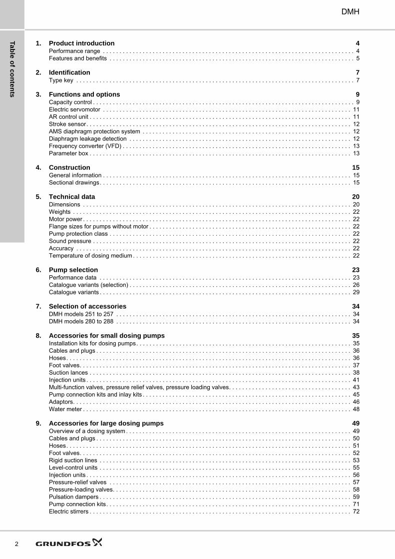
1. Product introduction
Performance range
Fig. 1 DMH 25x performance range
Fig. 2 DMH 28x performance range
TM
04
89
79
32
13
0
16
10
4
25
1 100 1000010 1000
25
1 2
5 b
ar
25
7 4
ba
r
25
7 1
0 b
ar
25
5 1
0 b
ar
25
4 1
0 b
ar
25
3 1
0 b
ar
25
2 1
0 b
ar
25
1 1
0 b
ar
25
2 1
6 b
ar
25
4 1
6 b
ar
25
7 1
6 b
ar
25
1 1
6 b
ar
P [bar]
Q [l/h]
TM
04
89
80
32
13
0
200
100
50
1 100 1000010 1000
P [bar]
Q [l/h]
28
6 5
0 b
ar
28
5 1
00
ba
r
28
3 1
00
ba
r
28
1 1
00
ba
r
28
7 2
00
ba
r
28
8 2
00
ba
r
28
0 2
00
ba
r
Pro
du
ct
intr
od
uc
tio
n
DMH 1
Features and benefits
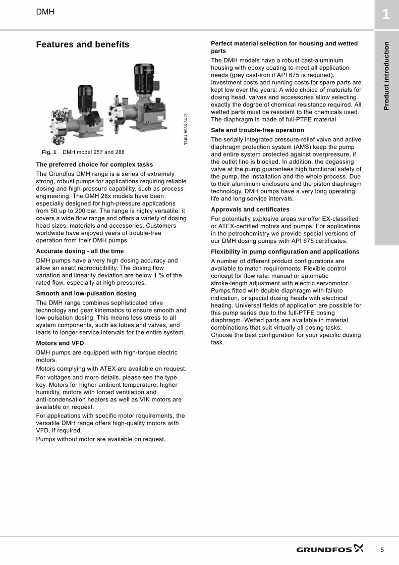
Fig. 1 DMH model 257 and 288
The preferred choice for complex tasks
The Grundfos DMH range is a series of extremely strong, robust pumps for applications requiring reliable dosing and high-pressure capability, such as process engineering. The DMH 28x models have been especially designed for high-pressure applications from 50 up to 200 bar. The range is highly versatile: it covers a wide flow range and offers a variety of dosing head sizes, materials and accessories. Customers worldwide have enjoyed years of trouble-free operation from their DMH pumps.
Accurate dosing - all the time
DMH pumps have a very high dosing accuracy and allow an exact reproducibility. The dosing flow variation and linearity deviation are below 1 % of the rated flow, especially at high pressures.
Smooth and low-pulsation dosing
The DMH range combines sophisticated drive technology and gear kinematics to ensure smooth and low-pulsation dosing. This means less stress to all system components, such as tubes and valves, and leads to longer service intervals for the entire system.
Motors and VFD
DMH pumps are equipped with high-torque electric motors.
Motors complying with ATEX are available on request.
For voltages and more details, please see the type key. Motors for higher ambient temperature, higher humidity, motors with forced ventilation and anti-condensation heaters as well as VIK motors are available on request.
For applications with specific motor requirements, the versatile DMH range offers high-quality motors with VFD, if required.
Pumps without motor are available on request.
Perfect material selection for housing and wetted parts
The DMH models have a robust cast-aluminium housing with epoxy coating to meet all application needs (grey cast-iron if API 675 is required). Investment costs and running costs for spare parts are kept low over the years: A wide choice of materials for dosing head, valves and accessories allow selecting exactly the degree of chemical resistance required. All wetted parts must be resistant to the chemicals used. The diaphragm is made of full-PTFE material
Safe and trouble-free operation
The serially integrated pressure-relief valve and active diaphragm protection system (AMS) keep the pump and entire system protected against overpressure, if the outlet line is blocked. In addition, the degassing valve at the pump guarantees high functional safety of the pump, the installation and the whole process. Due to their aluminium enclosure and the piston diaphragm technology, DMH pumps have a very long operating life and long service intervals.
Approvals and certificates
For potentially explosive areas we offer EX-classified or ATEX-certified motors and pumps. For applications in the petrochemistry we provide special versions of our DMH dosing pumps with API 675 certificates.
Flexibility in pump configuration and applications
A number of different product configurations are available to match requirements. Flexible control concept for flow rate: manual or automatic stroke-length adjustment with electric servomotor. Pumps fitted with double diaphragm with failure indication, or special dosing heads with electrical heating. Universal fields of application are possible for this pump series due to the full-PTFE dosing diaphragm. Wetted parts are available in material combinations that suit virtually all dosing tasks. Choose the best configuration for your specific dosing task.
TM
04
89
86
34
13
5
Pro
du
ct in
trod
uc
tion
6
DMH1
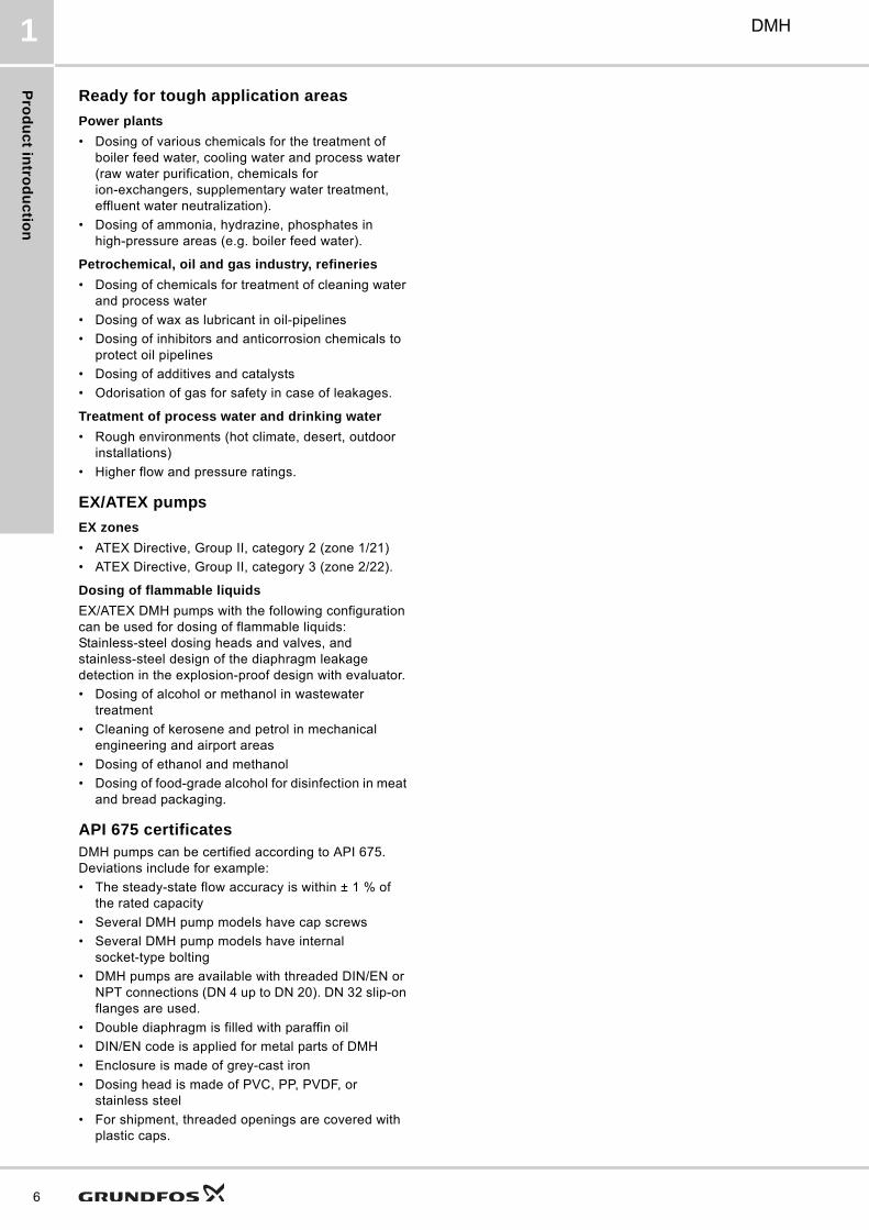
Ready for tough application areas
Power plants
• Dosing of various chemicals for the treatment of boiler feed water, cooling water and process water (raw water purification, chemicals for ion-exchangers, supplementary water treatment, effluent water neutralization).
• Dosing of ammonia, hydrazine, phosphates in high-pressure areas (e.g. boiler feed water).
Petrochemical, oil and gas industry, refineries
• Dosing of chemicals for treatment of cleaning water and process water
• Dosing of wax as lubricant in oil-pipelines
• Dosing of inhibitors and anticorrosion chemicals to protect oil pipelines
• Dosing of additives and catalysts
• Odorisation of gas for safety in case of leakages.
Treatment of process water and drinking water
• Rough environments (hot climate, desert, outdoor installations)
• Higher flow and pressure ratings.
EX/ATEX pumps
EX zones
• ATEX Directive, Group II, category 2 (zone 1/21)
• ATEX Directive, Group II, category 3 (zone 2/22).
Dosing of flammable liquids
EX/ATEX DMH pumps with the following configuration can be used for dosing of flammable liquids: Stainless-steel dosing heads and valves, and stainless-steel design of the diaphragm leakage detection in the explosion-proof design with evaluator.
• Dosing of alcohol or methanol in wastewater treatment
• Cleaning of kerosene and petrol in mechanical engineering and airport areas
• Dosing of ethanol and methanol
• Dosing of food-grade alcohol for disinfection in meat and bread packaging.
API 675 certificatesDMH pumps can be certified according to API 675. Deviations include for example:
• The steady-state flow accuracy is within ± 1 % of the rated capacity
• Several DMH pump models have cap screws
• Several DMH pump models have internal socket-type bolting
• DMH pumps are available with threaded DIN/EN or NPT connections (DN 4 up to DN 20). DN 32 slip-on flanges are used.
• Double diaphragm is filled with paraffin oil
• DIN/EN code is applied for metal parts of DMH
• Enclosure is made of grey-cast iron
• Dosing head is made of PVC, PP, PVDF, or stainless steel
• For shipment, threaded openings are covered with plastic caps.
Ide
nti
fic
ati
on
DMH 2
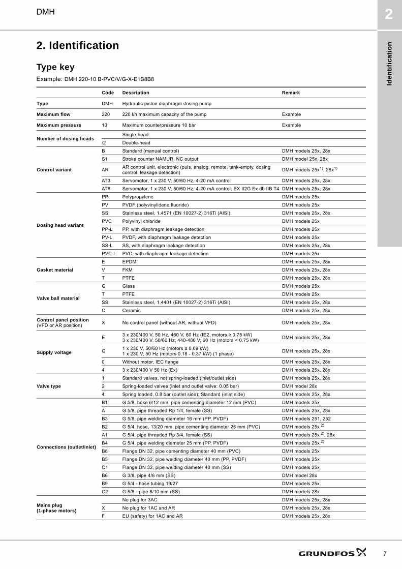
2. Identification
Type keyExample: DMH 220-10 B-PVC/V/G-X-E1B8B8
Code Description Remark
Type DMH Hydraulic piston diaphragm dosing pump
Maximum flow 220 220 l/h maximum capacity of the pump Example
Maximum pressure 10 Maximum counterpressure 10 bar Example
Number of dosing headsSingle-head
/2 Double-head
Control variant
B Standard (manual control) DMH models 25x, 28x
S1 Stroke counter NAMUR, NC output DMH model 25x, 28x
ARAR control unit, electronic (puls, analog, remote, tank-empty, dosing control, leakage detection)
DMH models 25x1), 28x1)
AT3 Servomotor, 1 x 230 V, 50/60 Hz, 4-20 mA control DMH models 25x, 28x
AT6 Servomotor, 1 x 230 V, 50/60 Hz, 4-20 mA control, EX II2G Ex db IIB T4 DMH models 25x, 28x
Dosing head variant
PP Polypropylene DMH models 25x
PV PVDF (polyvinylidene fluoride) DMH models 25x
SS Stainless steel, 1.4571 (EN 10027-2) 316Ti (AISI) DMH models 25x, 28x
PVC Polyvinyl chloride DMH models 25x
PP-L PP, with diaphragm leakage detection DMH models 25x
PV-L PVDF, with diaphragm leakage detection DMH models 25x
SS-L SS, with diaphragm leakage detection DMH models 25x, 28x
PVC-L PVC, with diaphragm leakage detection DMH models 25x
Gasket material
E EPDM DMH models 25x, 28x
V FKM DMH models 25x, 28x
T PTFE DMH models 25x, 28x
Valve ball material
G Glass DMH models 25x
T PTFE DMH models 25x
SS Stainless steel, 1.4401 (EN 10027-2) 316Ti (AISI) DMH models 25x, 28x
C Ceramic DMH models 25x, 28x
Control panel position(VFD or AR position)
X No control panel (without AR, without VFD) DMH models 25x, 28x
Supply voltage
E3 x 230/400 V, 50 Hz, 460 V, 60 Hz (IE2, motors ≥ 0.75 kW)3 x 230/400 V, 50/60 Hz, 440-480 V, 60 Hz (motors < 0.75 kW)
DMH models 25x, 28x
G1 x 230 V, 50/60 Hz (motors ≤ 0.09 kW)1 x 230 V, 50 Hz (motors 0.18 - 0.37 kW) (1 phase)
DMH models 25x, 28x
0 Without motor, IEC flange DMH models 25x, 28x
4 3 x 230/400 V 50 Hz (Ex) DMH models 25x, 28x
Valve type
1 Standard valves, not spring-loaded (inlet/outlet side) DMH models 25x, 28x
2 Spring-loaded valves (inlet and outlet valve: 0.05 bar) DMH model 28x
4 Spring loaded, 0.8 bar (outlet side); Standard (inlet side) DMH models 25x, 28x
Connections (outlet/inlet)
B1 G 5/8, hose 6/12 mm, pipe cementing diameter 12 mm (PVC) DMH models 25x
A G 5/8, pipe threaded Rp 1/4, female (SS) DMH models 25x, 28x
B3 G 5/8, pipe welding diameter 16 mm (PP, PVDF) DMH models 251, 252
B2 G 5/4, hose, 13/20 mm, pipe cementing diameter 25 mm (PVC) DMH models 25x 2)
A1 G 5/4, pipe threaded Rp 3/4, female (SS) DMH models 25x 2), 28x
B4 G 5/4, pipe welding diameter 25 mm (PP, PVDF) DMH models 25x 2)
B8 Flange DN 32, pipe cementing diameter 40 mm (PVC) DMH models 25x
B5 Flange DN 32, pipe welding diameter 40 mm (PP, PVDF) DMH models 25x
C1 Flange DN 32, pipe welding diameter 40 mm (SS) DMH models 25x
B6 G 3/8, pipe 4/6 mm (SS) DMH model 28x
B9 G 5/4 - hose tubing 19/27 DMH models 25x
C2 G 5/8 - pipe 8/10 mm (SS) DMH models 28x
Mains plug (1-phase motors)
No plug for 3AC DMH models 25x, 28x
X No plug for 1AC and AR DMH models 25x, 28x
F EU (safety) for 1AC and AR DMH models 25x, 28x
7
Ide
ntific
atio
n
8
DMH2
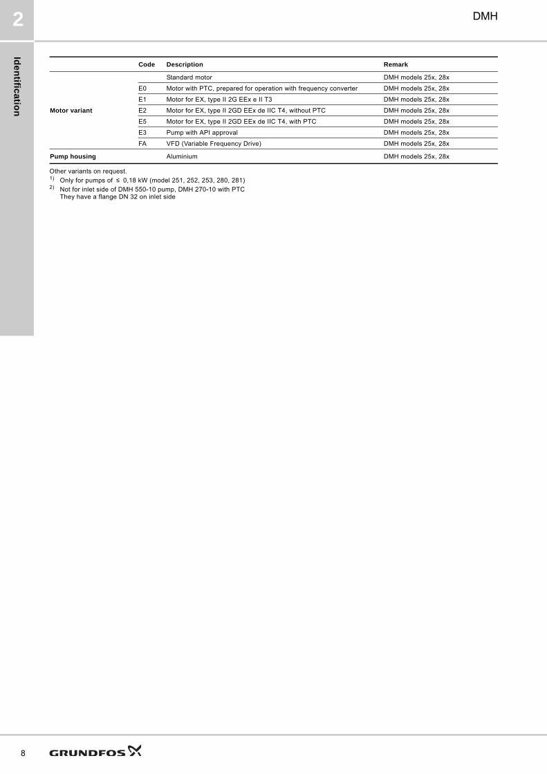
Other variants on request.1) Only for pumps of ≤ 0,18 kW (model 251, 252, 253, 280, 281)2) Not for inlet side of DMH 550-10 pump, DMH 270-10 with PTC
They have a flange DN 32 on inlet side
Motor variant
Standard motor DMH models 25x, 28x
E0 Motor with PTC, prepared for operation with frequency converter DMH models 25x, 28x
E1 Motor for EX, type II 2G EEx e II T3 DMH models 25x, 28x
E2 Motor for EX, type II 2GD EEx de IIC T4, without PTC DMH models 25x, 28x
E5 Motor for EX, type II 2GD EEx de IIC T4, with PTC DMH models 25x, 28x
E3 Pump with API approval DMH models 25x, 28x
FA VFD (Variable Frequency Drive) DMH models 25x, 28x
Pump housing Aluminium DMH models 25x, 28x
Code Description Remark
Fu
nc
tio
ns
an
d o
pti
on
s
DMH 3
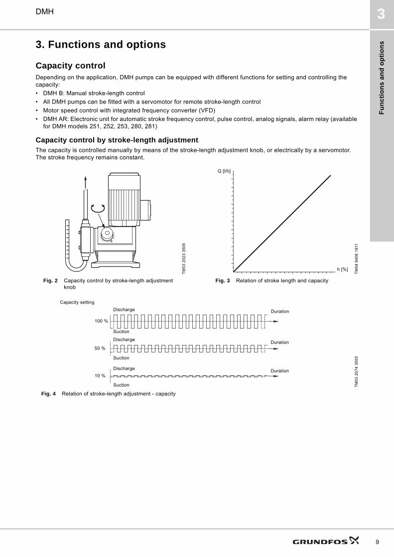
3. Functions and options
Capacity controlDepending on the application, DMH pumps can be equipped with different functions for setting and controlling the capacity:
• DMH B: Manual stroke-length control
• All DMH pumps can be fitted with a servomotor for remote stroke-length control
• Motor speed control with integrated frequency converter (VFD)
• DMH AR: Electronic unit for automatic stroke frequency control, pulse control, analog signals, alarm relay (available for DMH models 251, 252, 253, 280, 281)
Capacity control by stroke-length adjustmentThe capacity is controlled manually by means of the stroke-length adjustment knob, or electrically by a servomotor. The stroke frequency remains constant.
Fig. 4 Relation of stroke-length adjustment - capacity
TM
03
20
23
35
05
TM
04
84
06
18
11
Fig. 2 Capacity control by stroke-length adjustment knob
Fig. 3 Relation of stroke length and capacity
TM
03
20
74
35
05
Q [l/h]
h [%]
Discharge
Suction
Duration
Discharge
Suction
Duration
Discharge
Suction
Duration
Capacity setting
100 %
50 %
10 %
9
Fu
nc
tion
s a
nd
op
tion
s
10
DMH3
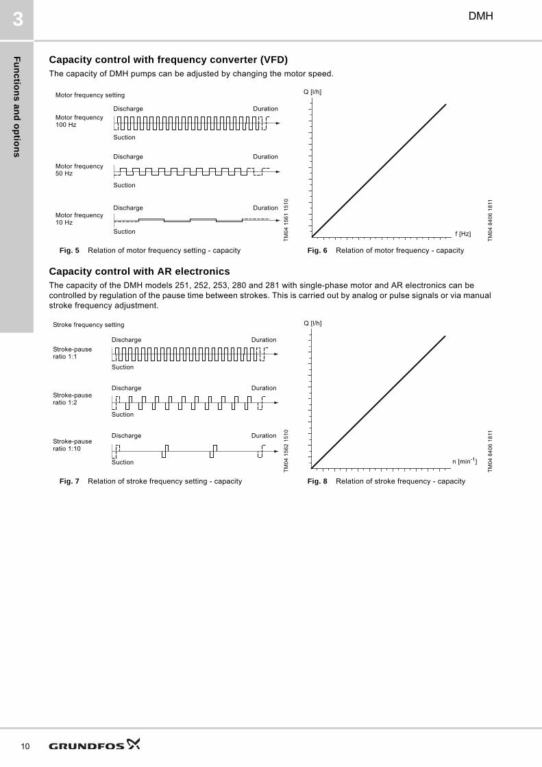
Capacity control with frequency converter (VFD)The capacity of DMH pumps can be adjusted by changing the motor speed.
Capacity control with AR electronicsThe capacity of the DMH models 251, 252, 253, 280 and 281 with single-phase motor and AR electronics can be controlled by regulation of the pause time between strokes. This is carried out by analog or pulse signals or via manual stroke frequency adjustment.
TM
04
15
61
15
10
TM
04
84
06
18
11
Fig. 5 Relation of motor frequency setting - capacity Fig. 6 Relation of motor frequency - capacity
Discharge
Suction
Duration
Discharge
Suction
Duration
Discharge
Suction
Duration
Motor frequency setting
Motor frequency 100 Hz
Motor frequency 50 Hz
Motor frequency 10 Hz
Q [l/h]
f [Hz]
TM
04
15
62
15
10
TM
04
84
06
18
11
Fig. 7 Relation of stroke frequency setting - capacity Fig. 8 Relation of stroke frequency - capacity
Discharge
Suction
Duration
Discharge
Suction
Duration
Discharge
Suction
Duration
Stroke frequency setting
Stroke-pause ratio 1:1
Stroke-pause ratio 1:2
Stroke-pause ratio 1:10
Q [l/h]
n [min-1]
Fu
nc
tio
ns
an
d o
pti
on
s
DMH 3
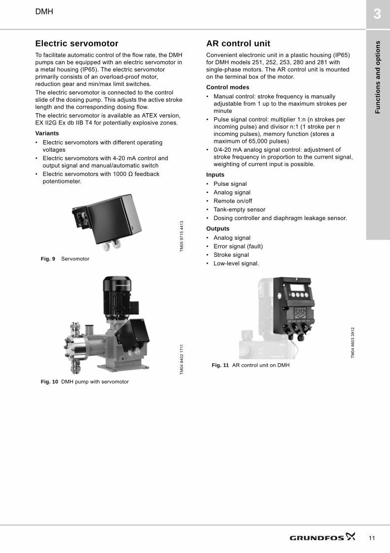
Electric servomotorTo facilitate automatic control of the flow rate, the DMH pumps can be equipped with an electric servomotor in a metal housing (IP65). The electric servomotor primarily consists of an overload-proof motor, reduction gear and min/max limit switches.
The electric servomotor is connected to the control slide of the dosing pump. This adjusts the active stroke length and the corresponding dosing flow.
The electric servomotor is available as ATEX version, EX II2G Ex db IIB T4 for potentially explosive zones.
Variants
• Electric servomotors with different operating voltages
• Electric servomotors with 4-20 mA control and output signal and manual/automatic switch
• Electric servomotors with 1000 Ω feedback potentiometer.
Fig. 9 Servomotor
Fig. 10 DMH pump with servomotor
AR control unitConvenient electronic unit in a plastic housing (IP65) for DMH models 251, 252, 253, 280 and 281 with single-phase motors. The AR control unit is mounted on the terminal box of the motor.
Control modes
• Manual control: stroke frequency is manually adjustable from 1 up to the maximum strokes per minute
• Pulse signal control: multiplier 1:n (n strokes per incoming pulse) and divisor n:1 (1 stroke per n incoming pulses), memory function (stores a maximum of 65,000 pulses)
• 0/4-20 mA analog signal control: adjustment of stroke frequency in proportion to the current signal, weighting of current input is possible.
Inputs
• Pulse signal
• Analog signal
• Remote on/off
• Tank-empty sensor
• Dosing controller and diaphragm leakage sensor.
Outputs
• Analog signal
• Error signal (fault)
• Stroke signal
• Low-level signal.
Fig. 11 AR control unit on DMH
TM
05
97
15
44
13
TM
04
84
02
17
11
TM
04
86
03
39
12
11
Fu
nc
tion
s a
nd
op
tion
s
12
DMH3
Stroke sensorDMH pumps with stroke sensor are especially designed for batch dosing and other mixing or filling tasks.
An optional inductive stroke sensor with NAMUR output can be mounted in the gear cover of a DMH pump.
AMS diaphragm protection systemThe unique diaphragm protection system AMS has a tactile surface (5) which touches the dosing diaphragm (4). If the inlet or outlet line is blocked due to a fault in the system, the tactile surface closes the hydraulic chamber (6). Although the piston (7) continues moving, the diaphragm cannot be overstretched.
Fig. 12 AMS diaphragm protection system
Legend
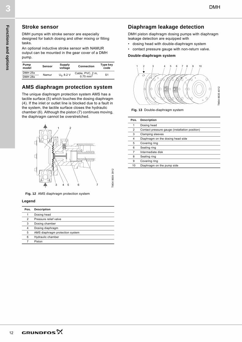
Diaphragm leakage detectionDMH piston diaphragm dosing pumps with diaphragm leakage detection are equipped with
• dosing head with double-diaphragm system
• contact pressure gauge with non-return valve.
Double-diaphragm system
Fig. 13 Double-diaphragm system
Pump model
SensorSupply voltage
ConnectionType key
code
DMH 25xNamur U0: 8.2 V
Cable, PVC, 2 m, 0.75 mm2 S1
DMH 28x
TM
04
86
04
39
12
Pos. Description
1 Dosing head
2 Pressure relief valve
3 Dosing chamber
4 Dosing diaphragm
5 AMS diaphragm protection system
6 Hydraulic chamber
7 Piston
1 2
3 4 5 6 7
TM
04
86
35
40
12
Pos. Description
1 Dosing head
2 Contact pressure gauge (installation position)
3 Clamping sleeves
4 Diaphragm on the dosing head side
5 Covering ring
6 Sealing ring
7 Intermediate disk
8 Sealing ring
9 Covering ring
10 Diaphragm on the pump side
4 10987652 31
Fu
nc
tio
ns
an
d o
pti
on
s
DMH 3
Contact pressure gauge with non-return valve
Fig. 14 Contact pressure gauge on a DMH dosing head
Fig. 15 Contact pressure gauge
Functional principle
The non-return valve and the gap between the diaphragms are filled with paraffin oil (separating agent) at the factory. If one of the diaphragms breaks, dosing medium or hydraulic oil flows into the gap between the diaphragms, and then into the valve.
The system pressure is applied to the valve, and the contact pressure gauge is activated. A potential-free reed contact can trigger an alarm or switch off the pump.
Fig. 16 DMH with contact pressure gauge for diaphragm leakage detection
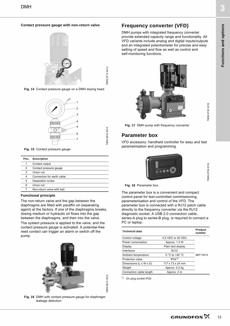
Frequency converter (VFD)DMH pumps with integrated frequency converter provide extended capacity range and functionality. All VFD variants include analog and digital inputs/outputs and an integrated potentiometer for precise and easy setting of speed and flow as well as control and self-monitoring functions.
Fig. 17 DMH pump with frequency converter
Parameter boxVFD accessory: handheld controller for easy and fast parametrisation and programming.
Fig. 18 Parameter box
The parameter box is a convenient and compact control panel for text-controlled commissioning, parameterisation and control of the VFD. The parameter box is connected with a RJ12 patch cable directly to the frequency converter via the RJ12 diagnostic socket. A USB 2.0 connection cable, series-A plug to series-B plug, is required to connect a PC or laptop.
1) On plug socket IP20
TM
05
97
14
44
13
TM
04
86
12
40
12
Pos. Description
1 Contact output
2 Contact pressure gauge
3 Union nut
4 Connection for earth cable
5 Deaeration screw
6 Union nut
7 Non-return valve with ball
TM
04
86
13
39
12
7
6
4
3
5
1
2
TM
06
67
38
23
16
TM
06
67
39
23
16
Technical dataProduct number
Control voltage 4.5 VDC to 30 VDC
98711813
Power consumption Approx. 1.3 W
Display Plain text display
Interfaces RJ12
Ambient temperature 0 °C to +40 °C
Protection class IP541)
Dimensions (L x W x D) 117 x 73 x 24 mm
Weight Approx. 0.2 kg
Connection cable length Approx. 2 m
13
Fu
nc
tion
s a
nd
op
tion
s
14
DMH3
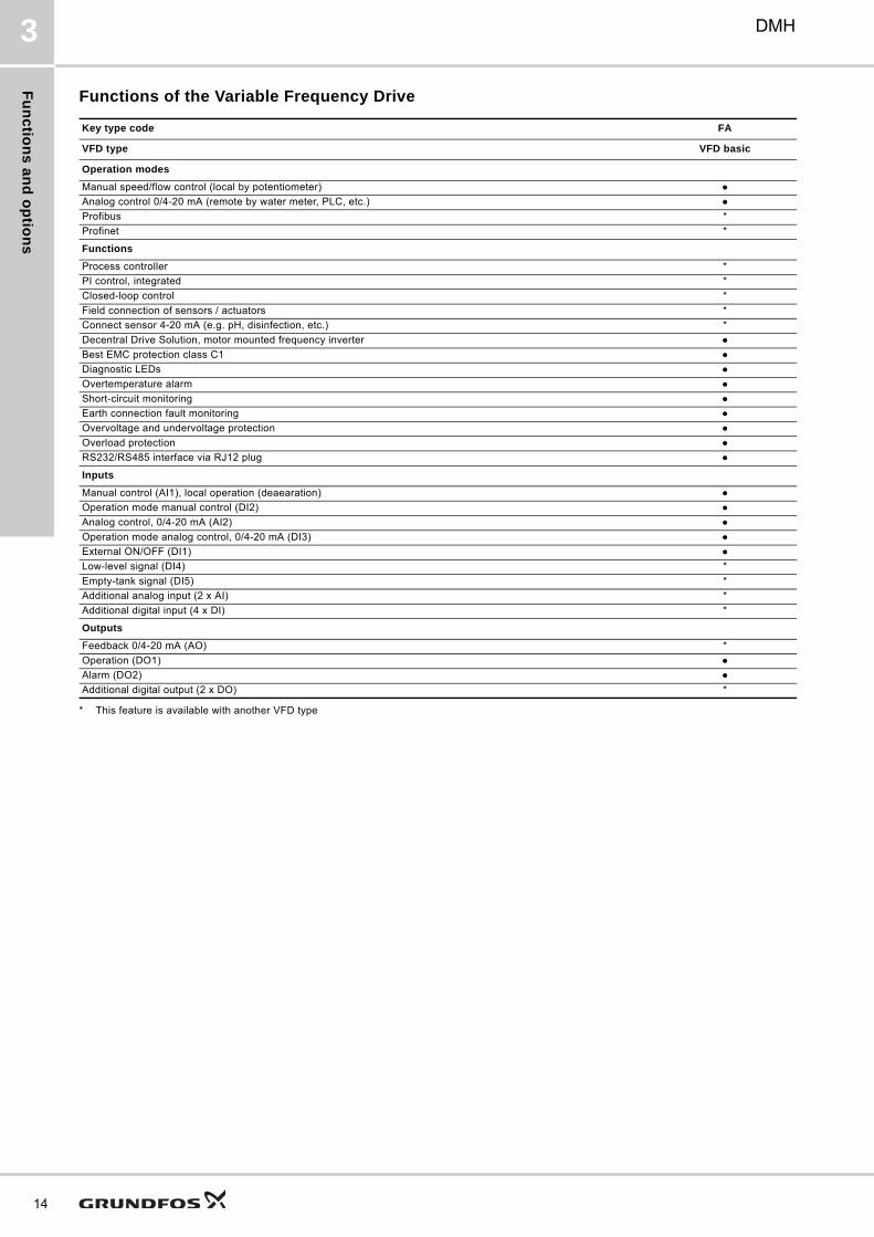
Functions of the Variable Frequency Drive
* This feature is available with another VFD type
Key type code FA
VFD type VFD basic
Operation modes
Manual speed/flow control (local by potentiometer)
Analog control 0/4-20 mA (remote by water meter, PLC, etc.)
Profibus *
Profinet *
Functions
Process controller *
PI control, integrated *
Closed-loop control *
Field connection of sensors / actuators *
Connect sensor 4-20 mA (e.g. pH, disinfection, etc.) *
Decentral Drive Solution, motor mounted frequency inverter
Best EMC protection class C1
Diagnostic LEDs
Overtemperature alarm
Short-circuit monitoring
Earth connection fault monitoring
Overvoltage and undervoltage protection
Overload protection
RS232/RS485 interface via RJ12 plug
Inputs
Manual control (AI1), local operation (deaearation)
Operation mode manual control (DI2)
Analog control, 0/4-20 mA (AI2)
Operation mode analog control, 0/4-20 mA (DI3)
External ON/OFF (DI1)
Low-level signal (DI4) *
Empty-tank signal (DI5) *
Additional analog input (2 x AI) *
Additional digital input (4 x DI) *
Outputs
Feedback 0/4-20 mA (AO) *
Operation (DO1)
Alarm (DO2)
Additional digital output (2 x DO) *
Co
ns
tru
cti
on
DMH 4
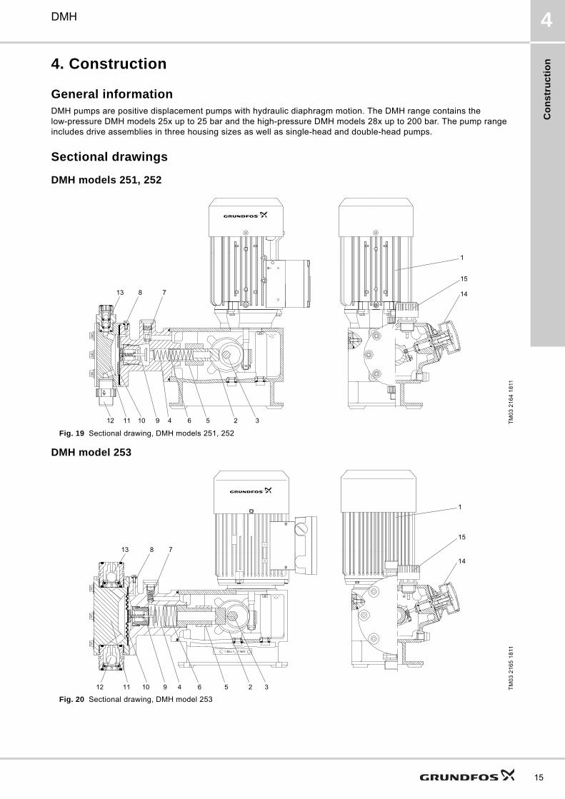
4. Construction
General informationDMH pumps are positive displacement pumps with hydraulic diaphragm motion. The DMH range contains the low-pressure DMH models 25x up to 25 bar and the high-pressure DMH models 28x up to 200 bar. The pump range includes drive assemblies in three housing sizes as well as single-head and double-head pumps.
Sectional drawings
DMH models 251, 252
Fig. 19 Sectional drawing, DMH models 251, 252
DMH model 253
Fig. 20 Sectional drawing, DMH model 253
TM
03
21
64
18
11
7813
12 9 325611 10
1
15
14
4
TM
03
21
65
18
11ce
7813
12 9 325611 10 4
1
15
14
15
Co
ns
truc
tion
16
DMH4
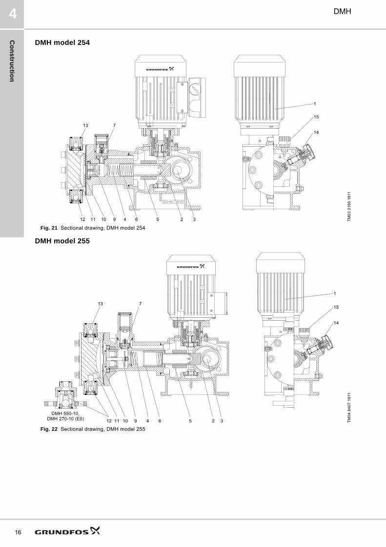
DMH model 254
Fig. 21 Sectional drawing, DMH model 254
DMH model 255
Fig. 22 Sectional drawing, DMH model 255
TM
03
21
66
18
11
ec
713
12 9 325611 10 4
1
15
14
TM
04
84
07
18
11
713
1
15
14
12 9 325411 10 6DMH 550-10,
DMH 270-10 (E0)
Co
ns
tru
cti
on
DMH 4
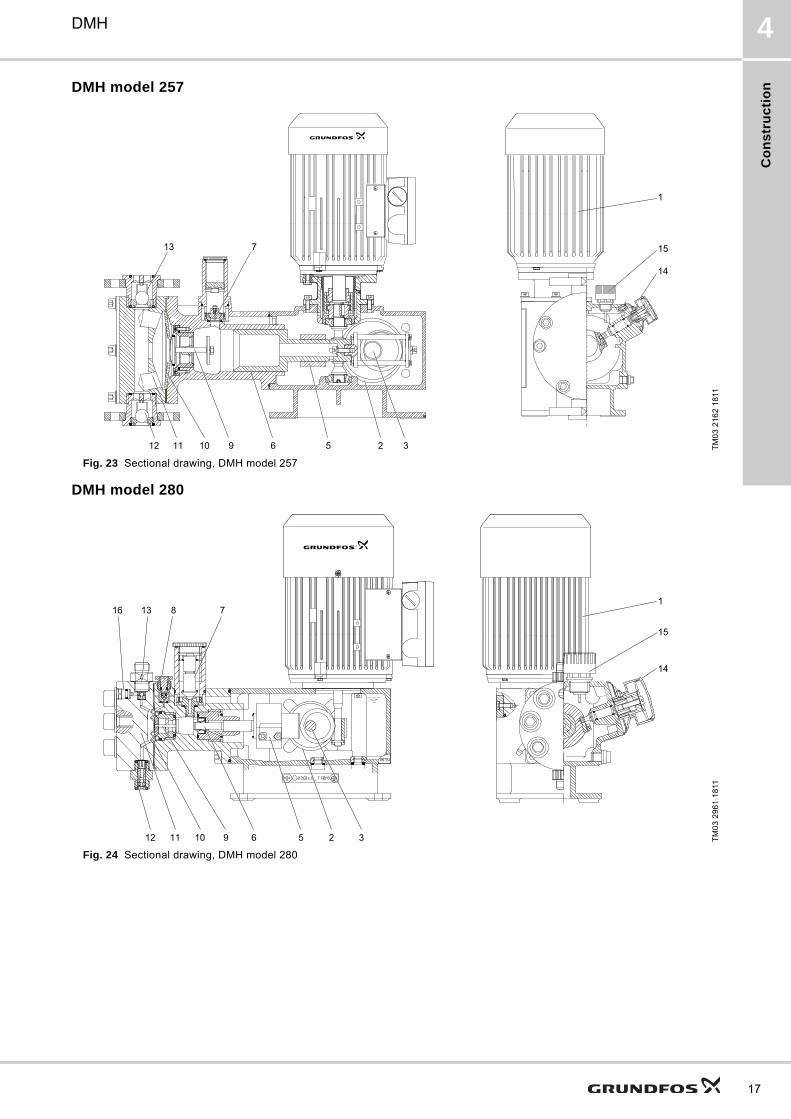
DMH model 257
Fig. 23 Sectional drawing, DMH model 257
DMH model 280
Fig. 24 Sectional drawing, DMH model 280
TM
03
21
62
18
11
713
12 9 325611 10
1
15
14
TM
03
29
61
18
11
781316
12 9 325611 10
1
15
14
17
Co
ns
truc
tion
18
DMH4
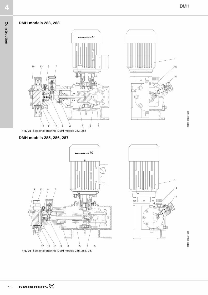
DMH models 283, 288
Fig. 25 Sectional drawing, DMH models 283, 288
DMH models 285, 286, 287
Fig. 26 Sectional drawing, DMH models 285, 286, 287
TM
03
29
63
18
11
781316
1
15
14
12 9 325611 10
TM
03
29
64
18
11781316
1
15
14
12 9 325611 10
Co
ns
tru
cti
on
DMH 4
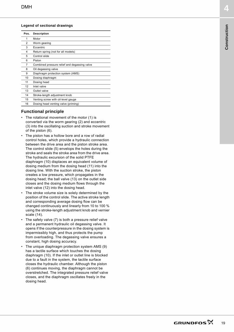
Legend of sectional drawings
Functional principle• The rotational movement of the motor (1) is
converted via the worm gearing (2) and eccentric (3) into the oscillating suction and stroke movement of the piston (6).
• The piston has a hollow bore and a row of radial control holes, which provide a hydraulic connection between the drive area and the piston stroke area. The control slide (5) envelops the holes during the stroke and seals the stroke area from the drive area. The hydraulic excursion of the solid PTFE diaphragm (10) displaces an equivalent volume of dosing medium from the dosing head (11) into the dosing line. With the suction stroke, the piston creates a low pressure, which propagates in the dosing head; the ball valve (13) on the outlet side closes and the dosing medium flows through the inlet valve (12) into the dosing head.
• The stroke volume size is solely determined by the position of the control slide. The active stroke length and corresponding average dosing flow can be changed continuously and linearly from 10 to 100 % using the stroke-length adjustment knob and vernier scale (14).
• The safety valve (7) is both a pressure relief valve and a permanent hydraulic oil degassing valve. It opens if the counterpressure in the dosing system is impermissibly high, and thus protects the pump from overloading. The degassing valve ensures a constant, high dosing accuracy.
• The unique diaphragm protection system AMS (9) has a tactile surface which touches the dosing diaphragm (10). If the inlet or outlet line is blocked due to a fault in the system, the tactile surface closes the hydraulic chamber. Although the piston (6) continues moving, the diaphragm cannot be overstretched. The integrated pressure relief valve closes, and the diaphragm oscillates freely in the dosing head.
Pos. Description
1 Motor
2 Worm gearing
3 Eccentric
4 Return spring (not for all models)
5 Control slide
6 Piston
7 Combined pressure relief and degassing valve
8 Oil degassing valve
9 Diaphragm protection system (AMS)
10 Dosing diaphragm
11 Dosing head
12 Inlet valve
13 Outlet valve
14 Stroke-length adjustment knob
15 Venting screw with oil-level gauge
16 Dosing head venting valve (priming)
19
Te
ch
nic
al d
ata
20
DMH5
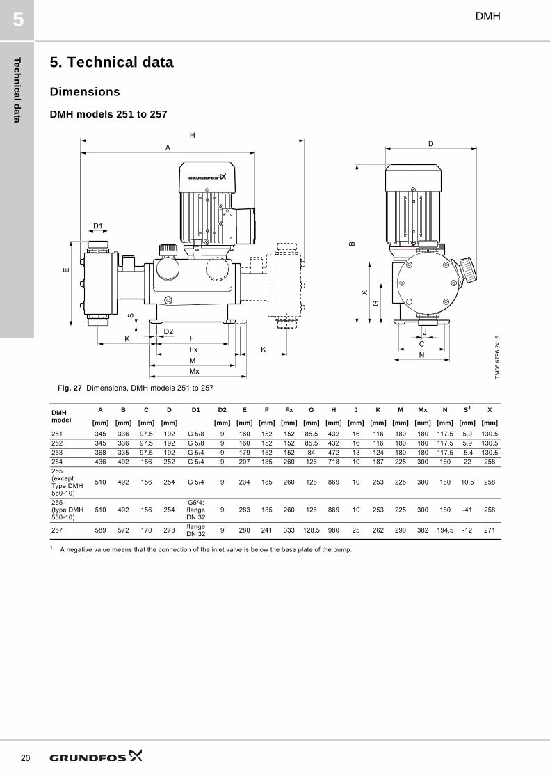
5. Technical data
Dimensions
DMH models 251 to 257
Fig. 27 Dimensions, DMH models 251 to 257
1 A negative value means that the connection of the inlet valve is below the base plate of the pump.
TM
06
67
96
24
16
H
A
D1
E
FFxMMx
D2K
KB
XG
D
NCJ
S
DMH model
A B C D D1 D2 E F Fx G H J K M Mx N S1 X
[mm] [mm] [mm] [mm] [mm] [mm] [mm] [mm] [mm] [mm] [mm] [mm] [mm] [mm] [mm] [mm] [mm]
251 345 336 97.5 192 G 5/8 9 160 152 152 85.5 432 16 116 180 180 117.5 5.9 130.5
252 345 336 97.5 192 G 5/8 9 160 152 152 85.5 432 16 116 180 180 117.5 5.9 130.5
253 368 335 97.5 192 G 5/4 9 179 152 152 84 472 13 124 180 180 117.5 -5.4 130.5
254 436 492 156 252 G 5/4 9 207 185 260 126 718 10 187 225 300 180 22 258
255(except Type DMH 550-10)
510 492 156 254 G 5/4 9 234 185 260 126 869 10 253 225 300 180 10.5 258
255 (type DMH 550-10)
510 492 156 254G5/4;flange DN 32
9 283 185 260 126 869 10 253 225 300 180 -41 258
257 589 572 170 278flange DN 32
9 280 241 333 128.5 980 25 262 290 382 194.5 -12 271
Te
ch
nic
al
da
ta
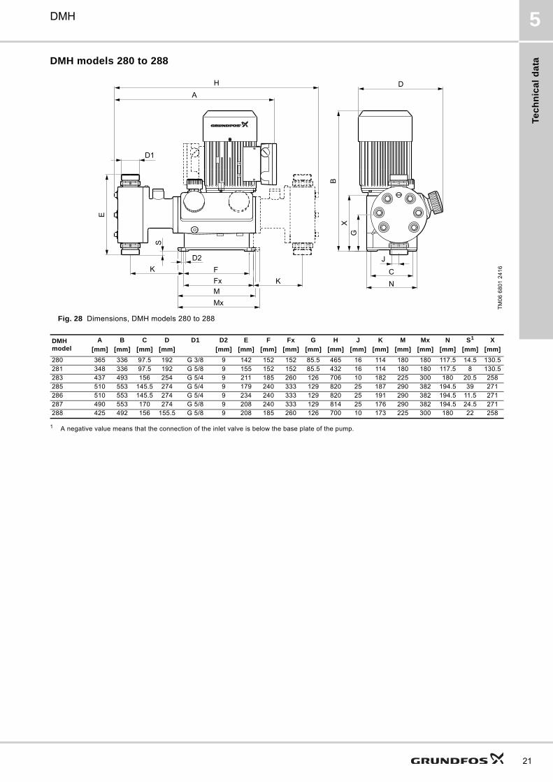
DMH 5
DMH models 280 to 288
Fig. 28 Dimensions, DMH models 280 to 288
1 A negative value means that the connection of the inlet valve is below the base plate of the pump.
TM
06
68
01
24
16
HA
D1
E
KD2
FFxMMx
K
BX
G
NC
J
D
S
DMH model
A B C D D1 D2 E F Fx G H J K M Mx N S1 X
[mm] [mm] [mm] [mm] [mm] [mm] [mm] [mm] [mm] [mm] [mm] [mm] [mm] [mm] [mm] [mm] [mm]
280 365 336 97.5 192 G 3/8 9 142 152 152 85.5 465 16 114 180 180 117.5 14.5 130.5281 348 336 97.5 192 G 5/8 9 155 152 152 85.5 432 16 114 180 180 117.5 8 130.5283 437 493 156 254 G 5/4 9 211 185 260 126 706 10 182 225 300 180 20.5 258285 510 553 145.5 274 G 5/4 9 179 240 333 129 820 25 187 290 382 194.5 39 271286 510 553 145.5 274 G 5/4 9 234 240 333 129 820 25 191 290 382 194.5 11.5 271287 490 553 170 274 G 5/8 9 208 240 333 129 814 25 176 290 382 194.5 24.5 271288 425 492 156 155.5 G 5/8 9 208 185 260 126 700 10 173 225 300 180 22 258
21
Te
ch
nic
al d
ata
22
DMH5
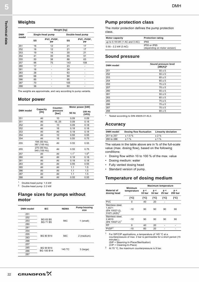
Weights
The weights are approximate, and vary according to pump variants.
Motor power
1 Double-head pump: 1.5 kW2 Double-head pump: 2.2 kW
Flange sizes for pumps without motor
Pump protection classThe motor protection defines the pump protection class.
Sound pressure
* Tested according to DIN 45635-01-KL3.
Accuracy
The values in the table above are in % of the full-scale value (max. dosing flow), based on the following conditions:
• Dosing flow within 10 to 100 % of the max. value
• Dosing medium: water
• Fully vented dosing head
• Standard version of pump.
Temperature of dosing medium
1 For SIP/CIP applications, a temperature of 145 °C at a counterpressure of max. 2 bar is permissible for a short period (15 minutes.).(SIP = Steaming-In-Place/Sterilisation)(CIP = Cleaning-In-Place)
2 At 70 °C, the maximum counterpressure is 9 bar.
DMH model
Weight [kg]
Single-head pump Double-head pump
SSPVC, PVDF,
PPSS
PVC, PVDF, PP
251 16 12 21 17
252 16 12 21 17
253 19 14 30 21
254 41 35 65 51
255 50 38 88 63
257 96 75 143 108
280 17 - 23 -
281 16 - 24 -
283 38 - 63 -
285 68 - 90 -
286 85 - 95 -
287 70 - 105 -
288 36 - 60 -
DMH modelCapacity
[l/h]
Counter-pressure
[bar]
Motor power [kW]
50 Hz100 Hz (VFD)
251 All 10 0.09 0.09
251 All 16, 25 0.09 0.18
252 All 10 0.09 0.18
252 All 16 0.18 0.18
253 All All 0.18 0.18
254 All 10 0.55 0.55
254 All 16 0.55 0.75
255194 (50 Hz), 387 (100 Hz)
All 0.55 0.55
255270 (50 Hz), 540 (100 Hz)
All 0.55 0.75
257 All All 1.11 1.52
280 All All 0.18 0.18
281 All All 0.18 0.18
283 All All 0.55 0.55
285 All All 1.1 1.5
286 All All 1.1 1.5
287 All All 1.1 1.5
288 All All 0.55 0.55
DMH model IEC NEMAPump housing
size
251
BG 63 B5BG 71 B5
56C 1 (small)
252
253
280
281
254
BG 80 B14 56C 2 (medium)255
283
288
257
BG 90 B14BG 100 B14
145 TC 3 (large)285
286
287
Motor capacity Protection rating
up to 0.18 kW (1 AC and 3 AC) IP65
0.55 - 2.2 kW (3 AC) IP55 or IP65 (depending on motor version)
DMH modelSound pressure level
[dB(A)]*
251 55 ± 5
252 55 ± 5
253 65 ± 5
254 65 ± 5
255 75 ± 5
257 75 ± 5
280 55 ± 5
281 55 ± 5
283 65 ± 5
285 75 ± 5
286 75 ± 5
287 75 ± 5
288 65 ± 5
DMH model Dosing flow fluctuation Linearity deviation
251 to 257 ± 1.5 % ± 2 %
280 to 288 ± 1 % ± 1 %
Material of dosing head
Minimum temperature
Maximum temperature
p < 10 bar
p <16 bar
p <25 bar
p <200 bar
[°C] [°C] [°C] [°C] [°C]
PVC 0 40 20 -
Stainless steel, 1.4571 (EN 10027-2),316Ti (AISI)1
-10 90 90 90 90
Stainless steel, 2.4610 (EN 10027-2)1
-10 90 90 90 90
PP 0 40 20 - -
PVDF2 -10 60 20 - -
Pu
mp
se
lec
tio
n
DMH 6
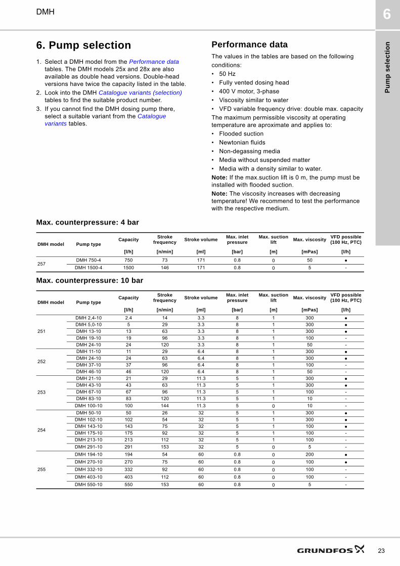
6. Pump selection
1. Select a DMH model from the Performance data tables. The DMH models 25x and 28x are also available as double head versions. Double-head versions have twice the capacity listed in the table.
2. Look into the DMH Catalogue variants (selection) tables to find the suitable product number.
3. If you cannot find the DMH dosing pump there, select a suitable variant from the Catalogue variants tables.
Performance data The values in the tables are based on the following
conditions:
• 50 Hz
• Fully vented dosing head
• 400 V motor, 3-phase
• Viscosity similar to water
• VFD variable frequency drive: double max. capacity
The maximum permissible viscosity at operating temperature are aproximate and applies to:
• Flooded suction
• Newtonian fluids
• Non-degassing media
• Media without suspended matter
• Media with a density similar to water.
Note: If the max.suction lift is 0 m, the pump must be installed with flooded suction.
Note: The viscosity increases with decreasing temperature! We recommend to test the performance with the respective medium.
Max. counterpressure: 4 bar
Max. counterpressure: 10 bar
DMH model Pump typeCapacity
Stroke frequency
Stroke volumeMax. inlet pressure
Max. suction lift
Max. viscosityVFD possible (100 Hz, PTC)
[l/h] [n/min] [ml] [bar] [m] [mPas] [l/h]
257DMH 750-4 750 73 171 0.8 0 50
DMH 1500-4 1500 146 171 0.8 0 5 -
DMH model Pump typeCapacity
Stroke frequency
Stroke volumeMax. inlet pressure
Max. suction lift
Max. viscosityVFD possible (100 Hz, PTC)
[l/h] [n/min] [ml] [bar] [m] [mPas] [l/h]
251
DMH 2,4-10 2.4 14 3.3 8 1 300 DMH 5,0-10 5 29 3.3 8 1 300 DMH 13-10 13 63 3.3 8 1 300 DMH 19-10 19 96 3.3 8 1 100 -
DMH 24-10 24 120 3.3 8 1 50 -
252
DMH 11-10 11 29 6.4 8 1 300 DMH 24-10 24 63 6.4 8 1 300 DMH 37-10 37 96 6.4 8 1 100 -
DMH 46-10 46 120 6.4 8 1 50 -
253
DMH 21-10 21 29 11.3 5 1 300 DMH 43-10 43 63 11.3 5 1 300 DMH 67-10 67 96 11.3 5 1 100 -
DMH 83-10 83 120 11.3 5 1 10 -
DMH 100-10 100 144 11.3 5 0 10 -
254
DMH 50-10 50 26 32 5 1 300 DMH 102-10 102 54 32 5 1 300 DMH 143-10 143 75 32 5 1 100 DMH 175-10 175 92 32 5 1 100 -
DMH 213-10 213 112 32 5 1 100 -
DMH 291-10 291 153 32 5 0 5 -
255
DMH 194-10 194 54 60 0.8 0 200 DMH 270-10 270 75 60 0.8 0 100 DMH 332-10 332 92 60 0.8 0 100 -
DMH 403-10 403 112 60 0.8 0 100 -
DMH 550-10 550 153 60 0.8 0 5 -
23
Pu
mp
se
lec
tion
24
DMH6
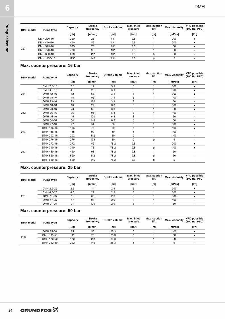
Max. counterpressure: 16 bar
Max. counterpressure: 25 bar
Max. counterpressure: 50 bar
257
DMH 220-10 220 28 131 0.8 1 200 DMH 440-10 440 56 131 0.8 1 200 DMH 575-10 575 73 131 0.8 1 50 DMH 770-10 770 98 131 0.8 1 50 -
DMH 880-10 880 112 131 0.8 0 50 -
DMH 1150-10 1150 146 131 0.8 0 5 -
DMH model Pump typeCapacity
Stroke frequency
Stroke volumeMax. inlet pressure
Max. suction lift
Max. viscosityVFD possible (100 Hz, PTC)
[l/h] [n/min] [ml] [bar] [m] [mPas] [l/h]
251
DMH 2,3-16 2.3 14 3.1 8 1 300 DMH 4,9-16 4.9 29 3.1 8 1 300 DMH 12-16 12 63 3.1 8 1 300 DMH 18-16 18 96 3.1 8 1 100 -
DMH 23-16 23 120 3.1 8 1 50 -
252
DMH 10-16 10 29 6.3 8 1 300 DMH 23-16 23 63 6.3 8 1 50 DMH 36-16 36 96 6.3 8 1 100 -
DMH 45-16 45 120 6.3 8 1 50 -
DMH 54-16 54 144 6.3 8 1 50 -
254
DMH 97-16 97 54 30 5 1 300 DMH 136-16 136 75 30 5 1 100 DMH 166-16 165 92 30 5 1 100 -
DMH 202-16 202 112 30 5 1 100 -
DMH 276-16 276 153 30 5 0 5 -
257
DMH 272-16 272 56 78.2 0.8 1 200 DMH 340-16 340 73 78.2 0.8 0 100 DMH 450-16 450 98 78.2 0.8 1 50 -
DMH 520-16 520 112 78.2 0.8 0 50 -
DMH 680-16 680 146 78.2 0.8 0 5 -
DMH model Pump typeCapacity
Stroke frequency
Stroke volumeMax. inlet pressure
Max. suction lift
Max. viscosityVFD possible (100 Hz, PTC)
[l/h] [n/min] [ml] [bar] [m] [mPas] [l/h]
DMH model Pump typeCapacity
Stroke frequency
Stroke volumeMax. inlet pressure
Max. suction lift
Max. viscosityVFD possible (100 Hz, PTC)
[l/h] [n/min] [ml] [bar] [m] [mPas] [l/h]
251
DMH 2,2-25 2.2 14 2.9 8 1 300 DMH 4,5-25 4.5 29 2.9 8 1 300 DMH 11-25 11 63 2.9 8 1 300 DMH 17-25 17 96 2.9 8 1 100 -
DMH 21-25 21 120 2.9 8 1 50 -
DMH model Pump typeCapacity
Stroke frequency
Stroke volumeMax. inlet pressure
Max. suction lift
Max. viscosityVFD possible (100 Hz, PTC)
[l/h] [n/min] [ml] [bar] [m] [mPas] [l/h]
286
DMH 85-50 85 56 25.3 5 1 100 DMH 111-50 111 73 25.3 5 1 50 DMH 170-50 170 112 25.3 5 1 50 -
DMH 222-50 222 146 25.3 5 1 5 -
Pu
mp
se
lec
tio
n
DMH 6
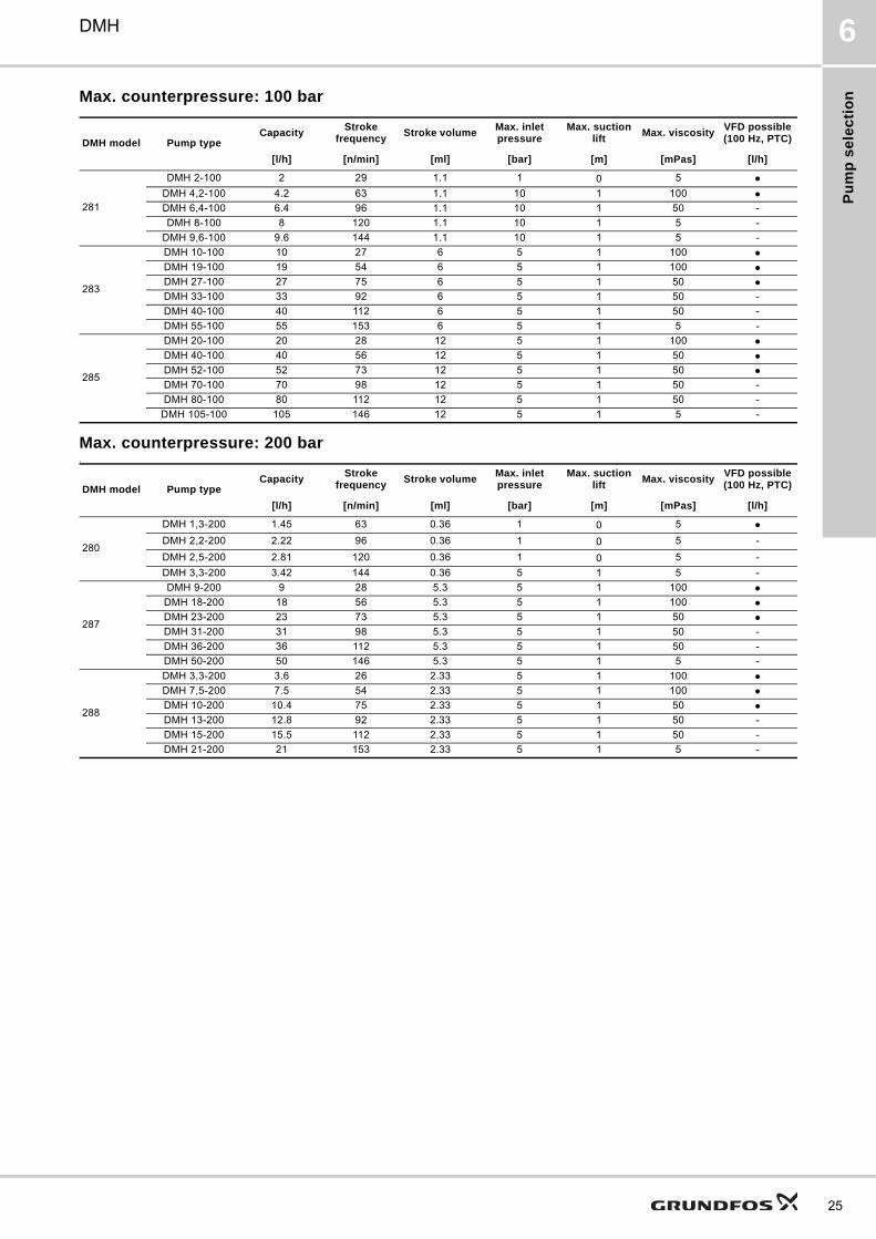
Max. counterpressure: 100 bar
Max. counterpressure: 200 bar1
DMH model Pump typeCapacity
Stroke frequency
Stroke volumeMax. inlet pressure
Max. suction lift
Max. viscosityVFD possible (100 Hz, PTC)
[l/h] [n/min] [ml] [bar] [m] [mPas] [l/h]
281
DMH 2-100 2 29 1.1 1 0 5 DMH 4,2-100 4.2 63 1.1 10 1 100 DMH 6,4-100 6.4 96 1.1 10 1 50 -
DMH 8-100 8 120 1.1 10 1 5 -
DMH 9,6-100 9.6 144 1.1 10 1 5 -
283
DMH 10-100 10 27 6 5 1 100 DMH 19-100 19 54 6 5 1 100 DMH 27-100 27 75 6 5 1 50 DMH 33-100 33 92 6 5 1 50 -
DMH 40-100 40 112 6 5 1 50 -
DMH 55-100 55 153 6 5 1 5 -
285
DMH 20-100 20 28 12 5 1 100 DMH 40-100 40 56 12 5 1 50 DMH 52-100 52 73 12 5 1 50 DMH 70-100 70 98 12 5 1 50 -
DMH 80-100 80 112 12 5 1 50 -
DMH 105-100 105 146 12 5 1 5 -
DMH model Pump typeCapacity
Stroke frequency
Stroke volumeMax. inlet pressure
Max. suction lift
Max. viscosityVFD possible (100 Hz, PTC)
[l/h] [n/min] [ml] [bar] [m] [mPas] [l/h]
280
DMH 1,3-200 1.45 63 0.36 1 0 5 DMH 2,2-200 2.22 96 0.36 1 0 5 -
DMH 2,5-200 2.81 120 0.36 1 0 5 -
DMH 3,3-200 3.42 144 0.36 5 1 5 -
287
DMH 9-200 9 28 5.3 5 1 100 DMH 18-200 18 56 5.3 5 1 100 DMH 23-200 23 73 5.3 5 1 50 DMH 31-200 31 98 5.3 5 1 50 -
DMH 36-200 36 112 5.3 5 1 50 -
DMH 50-200 50 146 5.3 5 1 5 -
288
DMH 3,3-200 3.6 26 2.33 5 1 100 DMH 7,5-200 7.5 54 2.33 5 1 100 DMH 10-200 10.4 75 2.33 5 1 50 DMH 13-200 12.8 92 2.33 5 1 50 -
DMH 15-200 15.5 112 2.33 5 1 50 -
DMH 21-200 21 153 2.33 5 1 5 -
25
Pu
mp
se
lec
tion
26
DMH6
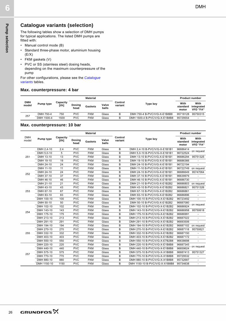
Catalogue variants (selection)The following tables show a selection of DMH pumps for typical applications. The listed DMH pumps are fitted with:
• Manual control mode (B)
• Standard three-phase motor, aluminium housing (E/X)
• FKM gaskets (V)
• PVC or SS (stainless steel) dosing heads, depending on the maximum counterpressure of the pump
For other configurations, please see the Catalogue variants tables.
Max. counterpressure: 4 bar
Max. counterpressure: 10 bar
DMH model
Pump typeCapacity
[l/h]
Material
Control variant
Type key
Product number
Dosing head
GasketsValve balls
With standard
motor
With integrated VFD "FA"
257DMH 750-4 750 PVC FKM Glass B DMH 750-4 B-PVC/V/G-X-E1B8B8 95718128 95750315
DMH 1500-4 1500 PVC FKM Glass B DMH 1500-4 B-PVC/V/G-X-E1B8B8 95729554 -
DMH model
Pump typeCapacity
[l/h]
Material
Control variant
Type key
Product number
Dosing head
GasketsValve balls
With standard
motor
With integrated VFD "FA"
251
DMH 2,4-10 2.4 PVC FKM Glass B DMH 2,4-10 B-PVC/V/G-X-E1B1B1 96686414on request
DMH 5,0-10 5 PVC FKM Glass B DMH 5,0-10 B-PVC/V/G-X-E1B1B1 96722524
DMH 13-10 13 PVC FKM Glass B DMH 13-10 B-PVC/V/G-X-E1B1B1 96686294 95751325
DMH 19-10 19 PVC FKM Glass B DMH 19-10 B-PVC/V/G-X-E1B1B1 96686366 -
DMH 24-10 24 PVC FKM Glass B DMH 24-10 B-PVC/V/G-X-E1B1B1 96722194 -
252
DMH 11-10 11 PVC FKM Glass B DMH 11-10 B-PVC/V/G-X-E1B1B1 96722749 on request
DMH 24-10 24 PVC FKM Glass B DMH 24-10 B-PVC/V/G-X-E1B1B1 96686649 95747064
DMH 37-10 37 PVC FKM Glass B DMH 37-10 B-PVC/V/G-X-E1B1B1 96639979 -
DMH 46-10 46 PVC FKM Glass B DMH 46-10 B-PVC/V/G-X-E1B1B1 96686730 -
253
DMH 21-10 21 PVC FKM Glass B DMH 21-10 B-PVC/V/G-X-E1B2B2 96686803 on request
DMH 43-10 43 PVC FKM Glass B DMH 43-10 B-PVC/V/G-X-E1B2B2 96686821 95751326
DMH 67-10 67 PVC FKM Glass B DMH 67-10 B-PVC/V/G-X-E1B2B2 96686861 -
DMH 83-10 83 PVC FKM Glass B DMH 83-10 B-PVC/V/G-X-E1B2B2 96686896 -
DMH 100-10 100 PVC FKM Glass B DMH 100-10 B-PVC/V/G-X-E1B2B2 96723492 -
254
DMH 50-10 50 PVC FKM Glass B DMH 50-10 B-PVC/V/G-X-E1B2B2 96687080on request
DMH 102-10 102 PVC FKM Glass B DMH 102-10 B-PVC/V/G-X-E1B2B2 96686924
DMH 143-10 143 PVC FKM Glass B DMH 143-10 B-PVC/V/G-X-E1B2B2 96686958 95750618
DMH 175-10 175 PVC FKM Glass B DMH 175-10 B-PVC/V/G-X-E1B2B2 96686991 -
DMH 213-10 213 PVC FKM Glass B DMH 213-10 B-PVC/V/G-X-E1B2B2 96687022 -
DMH 291-10 291 PVC FKM Glass B DMH 291-10 B-PVC/V/G-X-E1B2B2 96693506 -
255
DMH 194-10 194 PVC FKM Glass B DMH 194-10 B-PVC/V/G-X-E1B2B2 96687102 on request
DMH 270-10 270 PVC FKM Glass B DMH 270-10 B-PVC/V/G-X-E1B2B2 96687118 95750621
DMH 332-10 332 PVC FKM Glass B DMH 332-10 B-PVC/V/G-X-E1B2B2 96687150 -
DMH 403-10 403 PVC FKM Glass B DMH 403-10 B-PVC/V/G-X-E1B2B2 96687172 -
DMH 550-10 550 PVC FKM Glass B DMH 550-10 B-PVC/V/G-X-E7B2B8 96638698 -
257
DMH 220-10 220 PVC FKM Glass B DMH 220-10 B-PVC/V/G-X-E1B8B8 96687345on request
DMH 440-10 440 PVC FKM Glass B DMH 440-10 B-PVC/V/G-X-E1B8B8 96659624
DMH 575-10 575 PVC FKM Glass B DMH 575-10 B-PVC/V/G-X-X1B8B8 96687413 95751327
DMH 770-10 770 PVC FKM Glass B DMH 770-10 B-PVC/V/G-X-X1B8B8 95729532 -
DMH 880-10 880 PVC FKM Glass B DMH 880-10 B-PVC/V/G-X-X1B8B8 95732687 -
DMH 1150-10 1150 PVC FKM Glass B DMH 1150-10 B-PVC/V/G-X-X1B8B8 95734638 -
Pu
mp
se
lec
tio
n
DMH 6
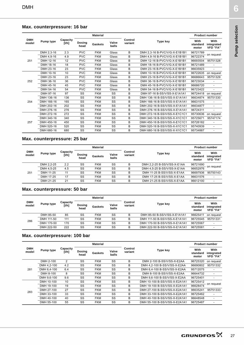
Max. counterpressure: 16 bar
Max. counterpressure: 25 bar
Max. counterpressure: 50 bar
Max. counterpressure: 100 bar
DMH model
Pump typeCapacity
[l/h]
Material
Control variant
Type key
Product number
Dosing head
GasketsValve balls
With standard
motor
With integrated VFD "FA"
251
DMH 2,3-16 2.3 PVC FKM Glass B DMH 2,3-16 B-PVC/V/G-X-E1B1B1 96721789on request
DMH 4,9-16 4.9 PVC FKM Glass B DMH 4,9-16 B-PVC/V/G-X-E1B1B1 96722374
DMH 12-16 12 PVC FKM Glass B DMH 12-16 B-PVC/V/G-X-E1B1B1 96693504 95751328
DMH 18-16 18 PVC FKM Glass B DMH 18-16 B-PVC/V/G-X-E1B1B1 96721489 -
DMH 23-16 23 PVC FKM Glass B DMH 23-16 B-PVC/V/G-X-E1B1B1 96635923 -
252
DMH 10-16 10 PVC FKM Glass B DMH 10-16 B-PVC/V/G-X-E1B1B1 96722635 on request
DMH 23-16 23 PVC FKM Glass B DMH 23-16 B-PVC/V/G-X-E1B1B1 96686643 95751329
DMH 36-16 36 PVC FKM Glass B DMH 36-16 B-PVC/V/G-X-E1B1B1 96723034 -
DMH 45-16 45 PVC FKM Glass B DMH 45-16 B-PVC/V/G-X-E1B1B1 96686720 -
DMH 54-16 54 PVC FKM Glass B DMH 54-16 B-PVC/V/G-X-E1B1B1 96723422 -
254
DMH 97-16 97 SS FKM SS B DMH 97-16 B-SS/V/SS-X-E1A1A1 96724418 on request
DMH 136-16 136 SS FKM SS B DMH 136-16 B-SS/V/SS-X-E1A1A1 96634874 95751330
DMH 166-16 165 SS FKM SS B DMH 166-16 B-SS/V/SS-X-E1A1A1 96631575 -
DMH 202-16 202 SS FKM SS B DMH 202-16 B-SS/V/SS-X-E1A1A1 96634877 -
DMH 276-16 276 SS FKM SS B DMH 276-16 B-SS/V/SS-X-E1A1A1 96724311 -
257
DMH 272-16 272 SS FKM SS B DMH 272-16 B-SS/V/SS-X-E1C1C1 95730636 on request
DMH 340-16 340 SS FKM SS B DMH 340-16 B-SS/V/SS-X-X1C1C1 95725671 95747174
DMH 450-16 450 SS FKM SS B DMH 450-16 B-SS/V/SS-X-E1C1C1 95726182 -
DMH 520-16 520 SS FKM SS B DMH 520-16 B-SS/V/SS-X-X1C1C1 95740939 -
DMH 680-16 680 SS FKM SS B DMH 680-16 B-SS/V/SS-X-X1C1C1 95734887 -
DMH model
Pump typeCapacity
[l/h]
Material
Control variant
Type key
Product number
Dosing head
GasketsValve balls
With standard
motor
With integrated VFD "FA"
251
DMH 2,2-25 2.2 SS FKM SS B DMH 2,2-25 B-SS/V/SS-X-E1AA 96721690on request
DMH 4,5-25 4.5 SS FKM SS B DMH 4,5-25 B-SS/V/SS-X-E1AA 96652976
DMH 11-25 11 SS FKM SS B DMH 11-25 B-SS/V/SS-X-E1AA 96697936 95750143
DMH 17-25 17 SS FKM SS B DMH 17-25 B-SS/V/SS-X-E1AA 96631576 -
DMH 21-25 21 SS FKM SS B DMH 21-25 B-SS/V/SS-X-E1AA 96612100 -
DMH model
Pump typeCapacity
[l/h]
Material
Control variant
Type key
Product number
Dosing head
GasketsValve balls
With standard
motor
With integrated VFD "FA"
286
DMH 85-50 85 SS FKM SS B DMH 85-50 B-SS/V/SS-X-E1A1A1 96625411 on request
DMH 111-50 111 SS FKM SS B DMH 111-50 B-SS/V/SS-X-E1A1A1 96725545 95751331
DMH 170-50 170 SS FKM SS B DMH 170-50 B-SS/V/SS-X-E1A1A1 96725567 -
DMH 222-50 222 SS FKM SS B DMH 222-50 B-SS/V/SS-X-E1A1A1 96725581 -
DMH model
Pump typeCapacity
[l/h]
Material
Control variant
Type key
Product number
Dosing head
GasketsValve balls
With standard
motor
With integrated VFD "FA"
281
DMH 2-100 2 SS FKM SS B DMH 2-100 B-SS/V/SS-X-E2AA 96725320 on request
DMH 4,2-100 4.2 SS FKM SS B DMH 4,2-100 B-SS/V/SS-X-E2AA 96690802 95751332
DMH 6,4-100 6.4 SS FKM SS B DMH 6,4-100 B-SS/V/SS-X-E2AA 95712075 -
DMH 8-100 8 SS FKM SS B DMH 8-100 B-SS/V/SS-X-E2AA 96644732 -
DMH 9,6-100 9.6 SS FKM SS B DMH 9,6-100 B-SS/V/SS-X-E2AA 96725401 -
283
DMH 10-100 10 SS FKM SS B DMH 10-100 B-SS/V/SS-X-E2A1A1 96725412on request
DMH 19-100 19 SS FKM SS B DMH 19-100 B-SS/V/SS-X-E2A1A1 96628474
DMH 27-100 27 SS FKM SS B DMH 27-100 B-SS/V/SS-X-E2A1A1 96635241 95751333
DMH 33-100 33 SS FKM SS B DMH 33-100 B-SS/V/SS-X-E2A1A1 96725462 -
DMH 40-100 40 SS FKM SS B DMH 40-100 B-SS/V/SS-X-E2A1A1 96648548 -
DMH 55-100 55 SS FKM SS B DMH 55-100 B-SS/V/SS-X-E2A1A1 96725487 -
27
Pu
mp
se
lec
tion
28
DMH6
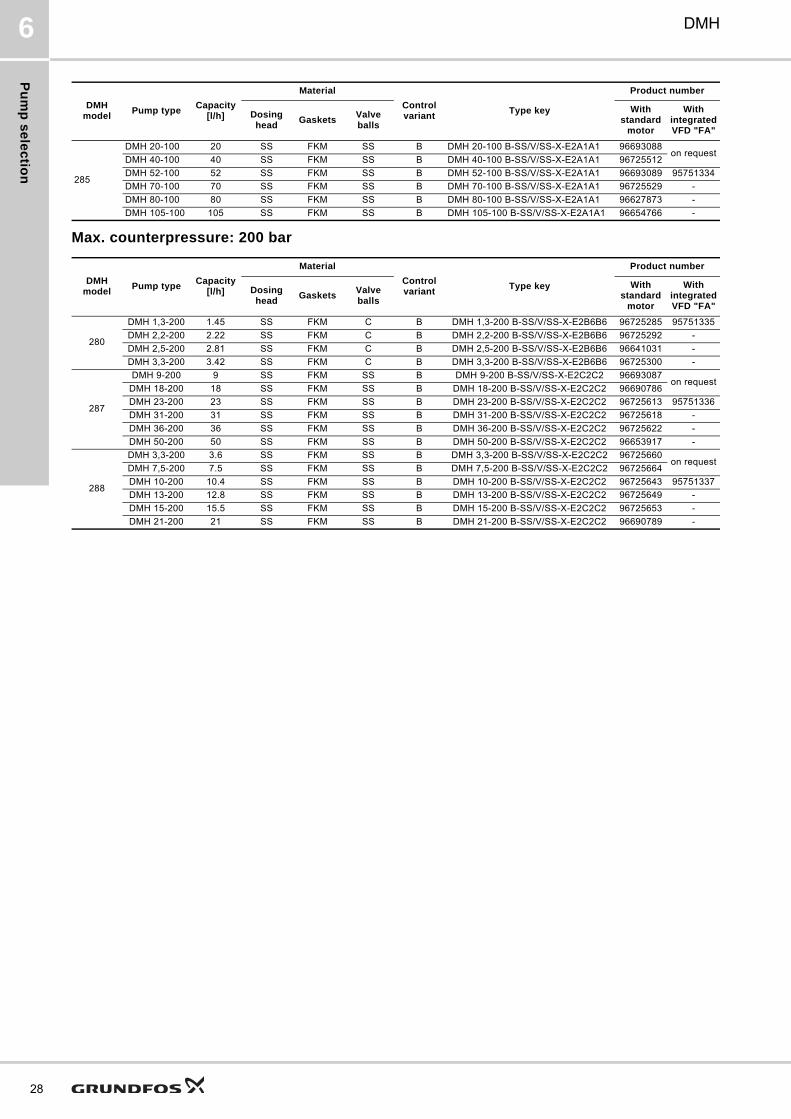
Max. counterpressure: 200 bar
285
DMH 20-100 20 SS FKM SS B DMH 20-100 B-SS/V/SS-X-E2A1A1 96693088on request
DMH 40-100 40 SS FKM SS B DMH 40-100 B-SS/V/SS-X-E2A1A1 96725512
DMH 52-100 52 SS FKM SS B DMH 52-100 B-SS/V/SS-X-E2A1A1 96693089 95751334
DMH 70-100 70 SS FKM SS B DMH 70-100 B-SS/V/SS-X-E2A1A1 96725529 -
DMH 80-100 80 SS FKM SS B DMH 80-100 B-SS/V/SS-X-E2A1A1 96627873 -
DMH 105-100 105 SS FKM SS B DMH 105-100 B-SS/V/SS-X-E2A1A1 96654766 -
DMH model
Pump typeCapacity
[l/h]
Material
Control variant
Type key
Product number
Dosing head
GasketsValve balls
With standard
motor
With integrated VFD "FA"
DMH model
Pump typeCapacity
[l/h]
Material
Control variant
Type key
Product number
Dosing head
GasketsValve balls
With standard
motor
With integrated VFD "FA"
280
DMH 1,3-200 1.45 SS FKM C B DMH 1,3-200 B-SS/V/SS-X-E2B6B6 96725285 95751335
DMH 2,2-200 2.22 SS FKM C B DMH 2,2-200 B-SS/V/SS-X-E2B6B6 96725292 -
DMH 2,5-200 2.81 SS FKM C B DMH 2,5-200 B-SS/V/SS-X-E2B6B6 96641031 -
DMH 3,3-200 3.42 SS FKM C B DMH 3,3-200 B-SS/V/SS-X-E2B6B6 96725300 -
287
DMH 9-200 9 SS FKM SS B DMH 9-200 B-SS/V/SS-X-E2C2C2 96693087on request
DMH 18-200 18 SS FKM SS B DMH 18-200 B-SS/V/SS-X-E2C2C2 96690786
DMH 23-200 23 SS FKM SS B DMH 23-200 B-SS/V/SS-X-E2C2C2 96725613 95751336
DMH 31-200 31 SS FKM SS B DMH 31-200 B-SS/V/SS-X-E2C2C2 96725618 -
DMH 36-200 36 SS FKM SS B DMH 36-200 B-SS/V/SS-X-E2C2C2 96725622 -
DMH 50-200 50 SS FKM SS B DMH 50-200 B-SS/V/SS-X-E2C2C2 96653917 -
288
DMH 3,3-200 3.6 SS FKM SS B DMH 3,3-200 B-SS/V/SS-X-E2C2C2 96725660on request
DMH 7,5-200 7.5 SS FKM SS B DMH 7,5-200 B-SS/V/SS-X-E2C2C2 96725664
DMH 10-200 10.4 SS FKM SS B DMH 10-200 B-SS/V/SS-X-E2C2C2 96725643 95751337
DMH 13-200 12.8 SS FKM SS B DMH 13-200 B-SS/V/SS-X-E2C2C2 96725649 -
DMH 15-200 15.5 SS FKM SS B DMH 15-200 B-SS/V/SS-X-E2C2C2 96725653 -
DMH 21-200 21 SS FKM SS B DMH 21-200 B-SS/V/SS-X-E2C2C2 96690789 -
Pu
mp
se
lec
tio
n
DMH 6
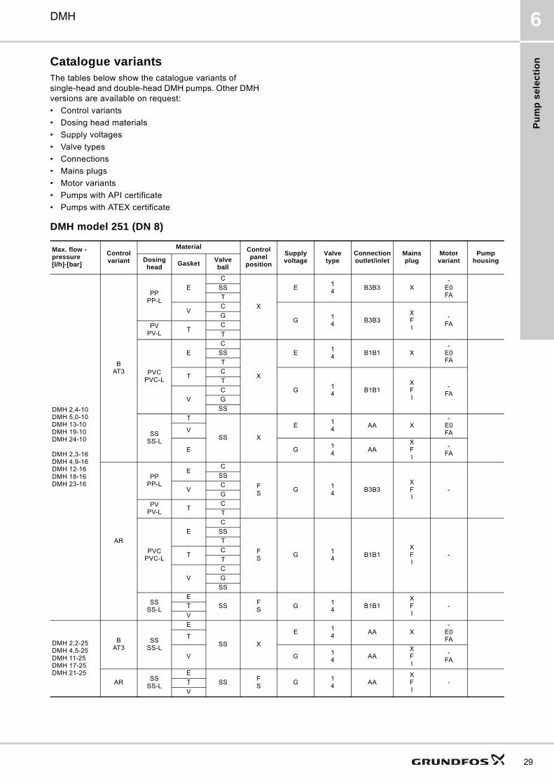
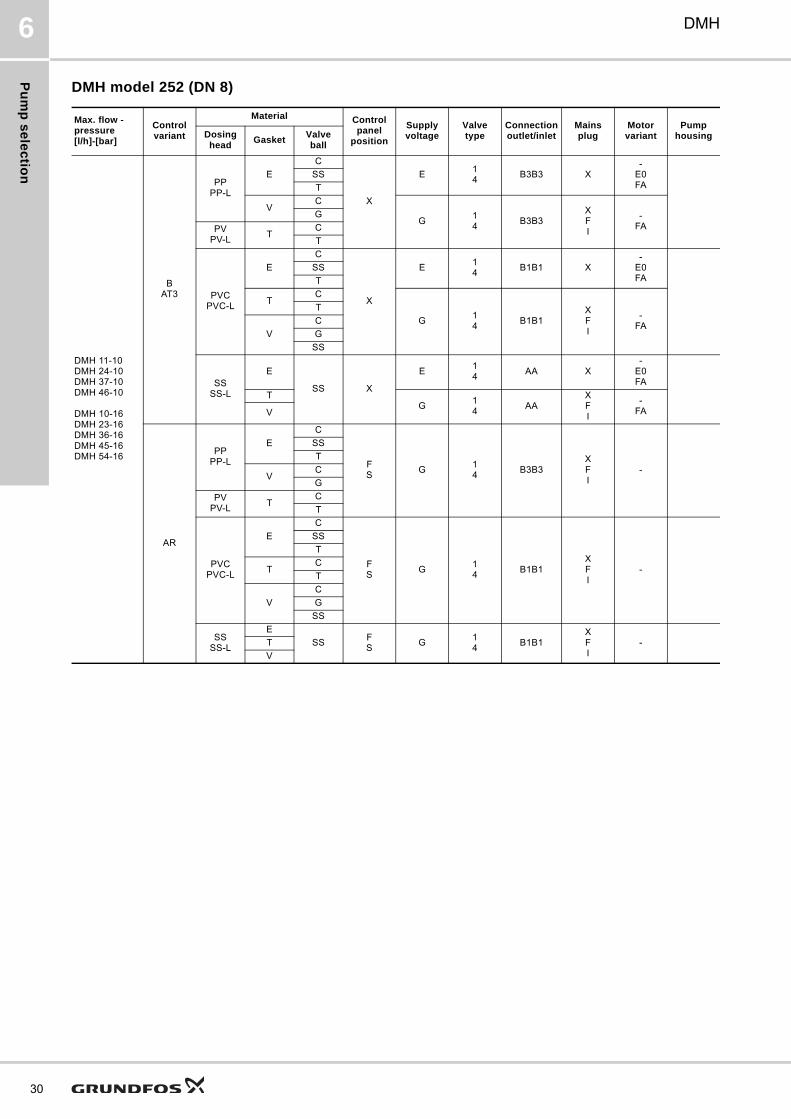
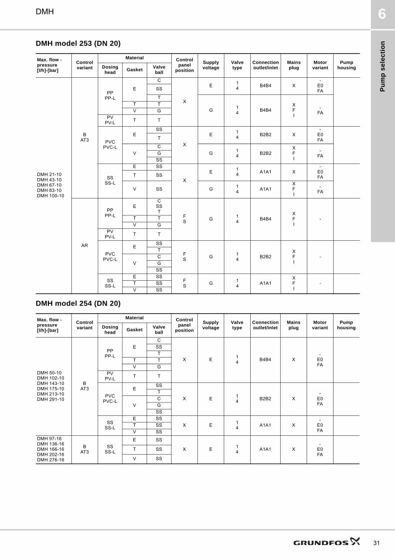
Catalogue variantsThe tables below show the catalogue variants of single-head and double-head DMH pumps. Other DMH versions are available on request:
• Control variants
• Dosing head materials
• Supply voltages
• Valve types
• Connections
• Mains plugs
• Motor variants
• Pumps with API certificate
• Pumps with ATEX certificate
DMH model 251 (DN 8)
Max. flow - pressure[l/h]-[bar]
Control variant
Material Control panel
position
Supply voltage
Valve type
Connection outlet/inlet
Mains plug
Motor variant
Pump housingDosing
headGasket
Valve ball
DMH 2,4-10DMH 5,0-10DMH 13-10DMH 19-10DMH 24-10
DMH 2,3-16DMH 4,9-16DMH 12-16DMH 18-16DMH 23-16
BAT3
PPPP-L
E
C
X
E14
B3B3 X-
E0FA
SS
T
VC
G14
B3B3XFI
-FA
G
PVPV-L
TC
T
PVCPVC-L
E
C
X
E14
B1B1 X-
E0FA
SS
T
TC
G14
B1B1XFI
-FA
T
V
C
G
SS
SSSS-L
T
SS X
E14
AA X-
E0FAV
E G14
AAXFI
-FA
AR
PPPP-L
EC
FS
G14
B3B3XFI
-
SS
VC
G
PVPV-L
TC
T
PVCPVC-L
E
C
FS
G14
B1B1XFI
-
SS
T
TC
T
V
C
G
SS
SSSS-L
E
SSFS
G14
B1B1XFI
-T
V
DMH 2,2-25DMH 4,5-25DMH 11-25DMH 17-25DMH 21-25
BAT3
SSSS-L
E
SS X
E14
AA X-
E0FAT
V G14
AAXFI
-FA
ARSS
SS-L
E
SSFS
G14
AAXFI
-T
V
29
Pu
mp
se
lec
tion
30
DMH6
DMH model 252 (DN 8)
Max. flow - pressure[l/h]-[bar]
Control variant
Material Control panel
position
Supply voltage
Valve type
Connection outlet/inlet
Mains plug
Motor variant
Pump housingDosing
headGasket
Valve ball
DMH 11-10DMH 24-10DMH 37-10DMH 46-10
DMH 10-16DMH 23-16DMH 36-16DMH 45-16DMH 54-16
BAT3
PPPP-L
E
C
X
E14
B3B3 X-
E0FA
SS
T
VC
G14
B3B3XFI
-FA
G
PVPV-L
TC
T
PVCPVC-L
E
C
X
E14
B1B1 X-
E0FA
SS
T
TC
G14
B1B1XFI
-FA
T
V
C
G
SS
SSSS-L
E
SS X
E14
AA X-
E0FA
TG
14
AAXFI
-FAV
AR
PPPP-L
E
C
FS
G14
B3B3XFI
-
SS
T
VC
G
PVPV-L
TC
T
PVCPVC-L
E
C
FS
G14
B1B1XFI
-
SS
T
TC
T
V
C
G
SS
SSSS-L
E
SSFS
G14
B1B1XFI
-T
V
Pu
mp
se
lec
tio
n
DMH 6
DMH model 253 (DN 20)
DMH model 254 (DN 20)
Max. flow - pressure[l/h]-[bar]
Control variant
Material Control panel
position
Supply voltage
Valve type
Connection outlet/inlet
Mains plug
Motor variant
Pump housingDosing
headGasket
Valve ball
DMH 21-10DMH 43-10DMH 67-10DMH 83-10DMH 100-10
BAT3
PPPP-L
E
C
X
E14
B4B4 X-
E0FASS
T
G14
B4B4XFI
-FA
T T
V G
PVPV-L
T T
PVCPVC-L
ESS
X
E14
B2B2 X-
E0FAT
V
C
G14
B2B2XFI
-FA
G
SS
SSSS-L
E SS
X
E14
A1A1 X-
E0FAT SS
V SS G14
A1A1XFI
-FA
AR
PPPP-L
EC
SST
FS
G14
B4B4XFI
-T T
V G
PVPV-L
T T
PVCPVC-L
ESS
FS
G14
B2B2XFI
-
T
V
C
G
SS
SSSS-L
E SSFS
G14
A1A1XFI
-T SS
V SS
Max. flow - pressure[l/h]-[bar]
Control variant
Material Control panel
position
Supply voltage
Valve type
Connection outlet/inlet
Mains plug
Motor variant
Pump housingDosing
headGasket
Valve ball
DMH 50-10DMH 102-10DMH 143-10DMH 175-10DMH 213-10DMH 291-10
BAT3
PPPP-L
E
C
X E14
B4B4 X-
E0FA
SS
T
T T
V G
PVPV-L
T T
PVCPVC-L
ESS
X E14
B2B2 X-
E0FA
T
V
C
G
SS
SSSS-L
E SS
X E14
A1A1 X-
E0FA
T SS
V SS
DMH 97-16DMH 136-16DMH 166-16DMH 202-16DMH 276-16
BAT3
SSSS-L
E SS
X E14
A1A1 X-
E0FA
T SS
V SS
31
Pu
mp
se
lec
tion
32
DMH6
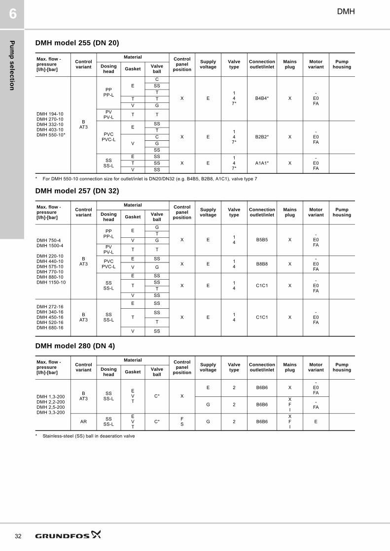
DMH model 255 (DN 20)
* For DMH 550-10 connection size for outlet/inlet is DN20/DN32 (e.g. B4B5, B2B8, A1C1), valve type 7
DMH model 257 (DN 32)
DMH model 280 (DN 4)
* Stainless-steel (SS) ball in deaeration valve
Max. flow - pressure[l/h]-[bar]
Control variant
Material Control panel
position
Supply voltage
Valve type
Connection outlet/inlet
Mains plug
Motor variant
Pump housingDosing
headGasket
Valve ball
DMH 194-10DMH 270-10DMH 332-10DMH 403-10DMH 550-10*
BAT3
PPPP-L
E
C
X E147*
B4B4* X-
E0FA
SS
T
T T
V G
PVPV-L
T T
PVCPVC-L
ESS
X E147*
B2B2* X-
E0FA
T
V
C
G
SS
SSSS-L
E SS
X E147*
A1A1* X-
E0FA
T SS
V SS
Max. flow - pressure[l/h]-[bar]
Control variant
Material Control panel
position
Supply voltage
Valve type
Connection outlet/inlet
Mains plug
Motor variant
Pump housingDosing
headGasket
Valve ball
DMH 750-4DMH 1500-4
DMH 220-10DMH 440-10DMH 575-10DMH 770-10DMH 880-10DMH 1150-10
BAT3
PPPP-L
EG
X E14
B5B5 X-
E0FA
T
V G
PVPV-L
T T
PVCPVC-L
E SSX E
14
B8B8 X-
E0FAV G
SSSS-L
E SS
X E14
C1C1 X-
E0FA
TSS
T
V SS
DMH 272-16DMH 340-16DMH 450-16DMH 520-16DMH 680-16
BAT3
SSSS-L
E SS
X E14
C1C1 X-
E0FA
TSS
T
V SS
Max. flow - pressure[l/h]-[bar]
Control variant
Material Control panel
position
Supply voltage
Valve type
Connection outlet/inlet
Mains plug
Motor variant
Pump housingDosing
headGasket
Valve ball
DMH 1,3-200DMH 2,2-200DMH 2,5-200DMH 3,3-200
BAT3
SSSS-L
EVT
C* X
E 2 B6B6 X-
E0FA
G 2 B6B6XFI
-FA
ARSS
SS-L
EVT
C*FS
G 2 B6B6XFI
E
Pu
mp
se
lec
tio
n
DMH 6
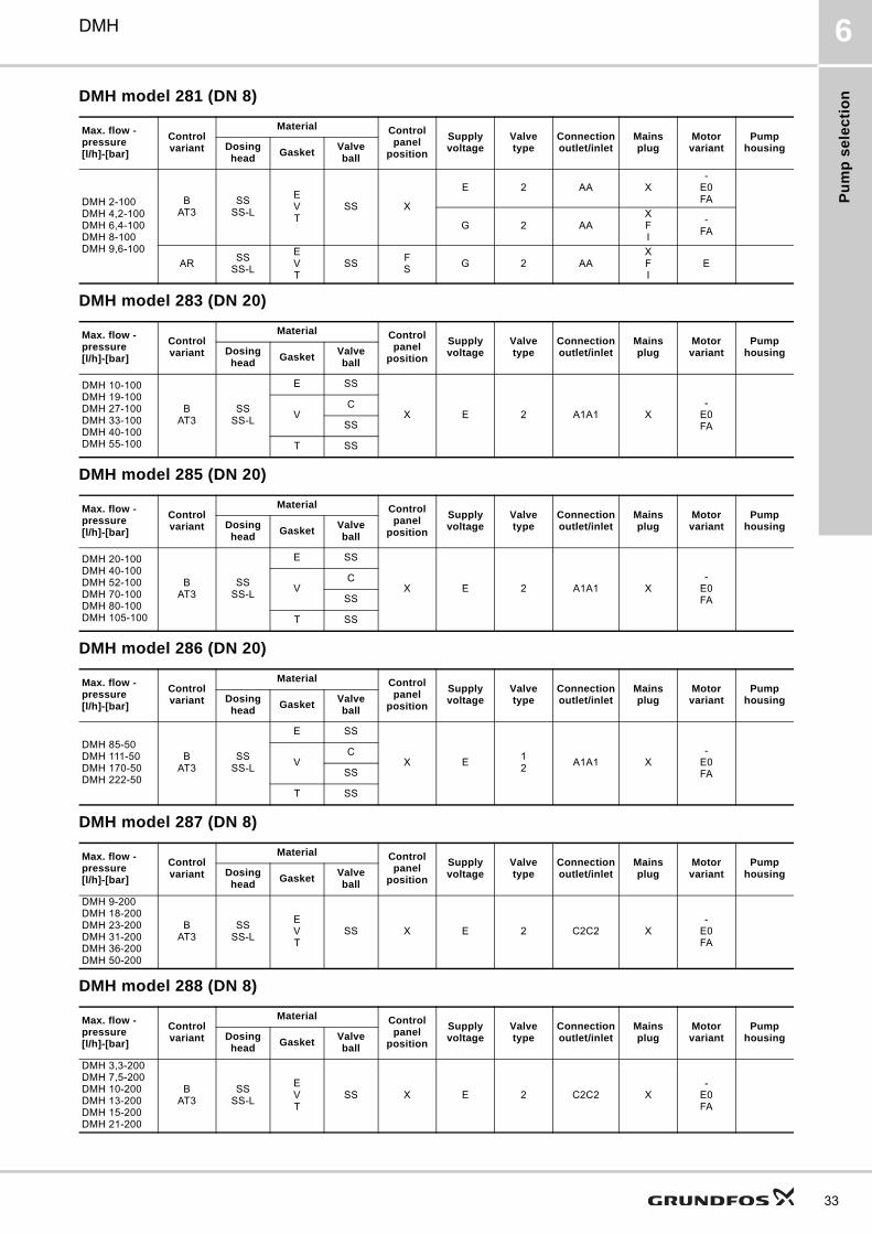
DMH model 281 (DN 8)
DMH model 283 (DN 20)
DMH model 285 (DN 20)
DMH model 286 (DN 20)
DMH model 287 (DN 8)
DMH model 288 (DN 8)
Max. flow - pressure[l/h]-[bar]
Control variant
Material Control panel
position
Supply voltage
Valve type
Connection outlet/inlet
Mains plug
Motor variant
Pump housingDosing
headGasket
Valve ball
DMH 2-100DMH 4,2-100DMH 6,4-100DMH 8-100DMH 9,6-100
BAT3
SSSS-L
EVT
SS X
E 2 AA X-
E0FA
G 2 AAXFI
-FA
ARSS
SS-L
EVT
SSFS
G 2 AAXFI
E
Max. flow - pressure[l/h]-[bar]
Control variant
Material Control panel
position
Supply voltage
Valve type
Connection outlet/inlet
Mains plug
Motor variant
Pump housingDosing
headGasket
Valve ball
DMH 10-100DMH 19-100DMH 27-100DMH 33-100DMH 40-100DMH 55-100
BAT3
SSSS-L
E SS
X E 2 A1A1 X-
E0FA
VC
SS
T SS
Max. flow - pressure[l/h]-[bar]
Control variant
Material Control panel
position
Supply voltage
Valve type
Connection outlet/inlet
Mains plug
Motor variant
Pump housingDosing
headGasket
Valve ball
DMH 20-100DMH 40-100DMH 52-100DMH 70-100DMH 80-100DMH 105-100
BAT3
SSSS-L
E SS
X E 2 A1A1 X-
E0FA
VC
SS
T SS
Max. flow - pressure[l/h]-[bar]
Control variant
Material Control panel
position
Supply voltage
Valve type
Connection outlet/inlet
Mains plug
Motor variant
Pump housingDosing
headGasket
Valve ball
DMH 85-50DMH 111-50DMH 170-50DMH 222-50
BAT3
SSSS-L
E SS
X E12
A1A1 X-
E0FA
VC
SS
T SS
Max. flow - pressure[l/h]-[bar]
Control variant
Material Control panel
position
Supply voltage
Valve type
Connection outlet/inlet
Mains plug
Motor variant
Pump housingDosing
headGasket
Valve ball
DMH 9-200DMH 18-200DMH 23-200DMH 31-200DMH 36-200DMH 50-200
BAT3
SSSS-L
EVT
SS X E 2 C2C2 X-
E0FA
Max. flow - pressure[l/h]-[bar]
Control variant
Material Control panel
position
Supply voltage
Valve type
Connection outlet/inlet
Mains plug
Motor variant
Pump housingDosing
headGasket
Valve ball
DMH 3,3-200DMH 7,5-200DMH 10-200DMH 13-200DMH 15-200DMH 21-200
BAT3
SSSS-L
EVT
SS X E 2 C2C2 X-
E0FA
33
Se
lec
tion
of a
cc
es
so
ries
34
DMH7
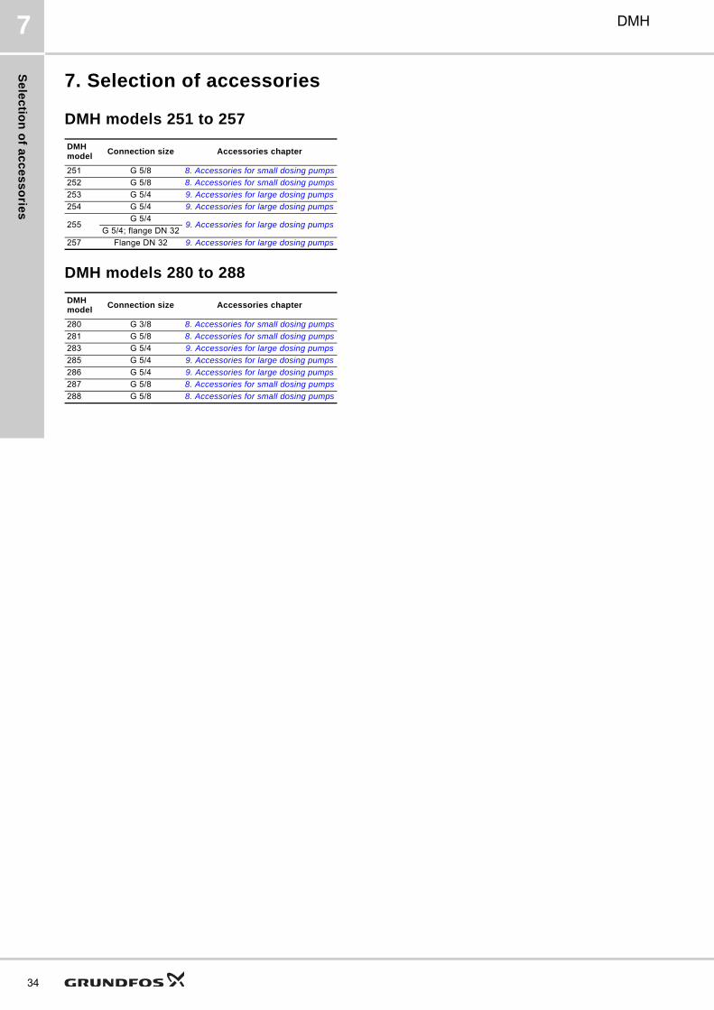
7. Selection of accessories
DMH models 251 to 257
DMH models 280 to 288
DMH model
Connection size Accessories chapter
251 G 5/8 8. Accessories for small dosing pumps
252 G 5/8 8. Accessories for small dosing pumps
253 G 5/4 9. Accessories for large dosing pumps
254 G 5/4 9. Accessories for large dosing pumps
255G 5/4
9. Accessories for large dosing pumpsG 5/4; flange DN 32
257 Flange DN 32 9. Accessories for large dosing pumps
DMH model
Connection size Accessories chapter
280 G 3/8 8. Accessories for small dosing pumps
281 G 5/8 8. Accessories for small dosing pumps
283 G 5/4 9. Accessories for large dosing pumps
285 G 5/4 9. Accessories for large dosing pumps
286 G 5/4 9. Accessories for large dosing pumps
287 G 5/8 8. Accessories for small dosing pumps
288 G 5/8 8. Accessories for small dosing pumps
Ac
ce
ss
ori
es
fo
r s
ma
ll d
os
ing
pu
mp
s
DMH 8
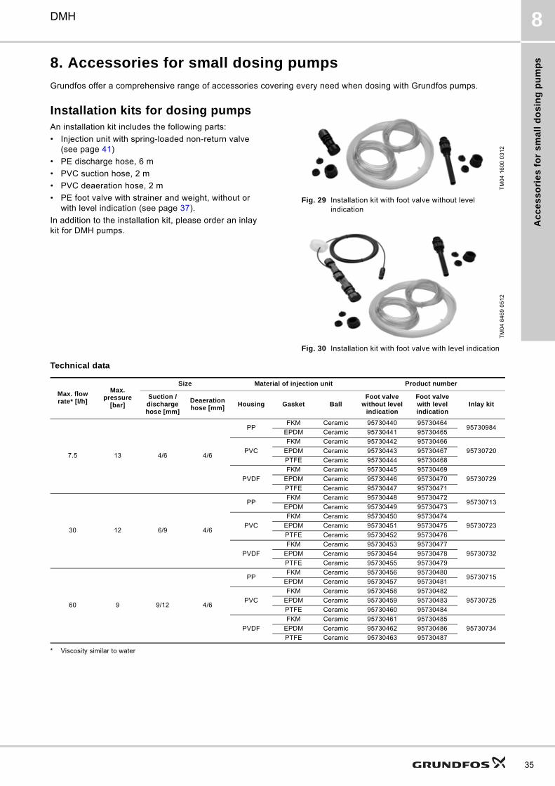
8. Accessories for small dosing pumps
Grundfos offer a comprehensive range of accessories covering every need when dosing with Grundfos pumps.
Installation kits for dosing pumpsAn installation kit includes the following parts:
• Injection unit with spring-loaded non-return valve (see page 41)
• PE discharge hose, 6 m
• PVC suction hose, 2 m
• PVC deaeration hose, 2 m
• PE foot valve with strainer and weight, without or with level indication (see page 37).
In addition to the installation kit, please order an inlay kit for DMH pumps.
Fig. 29 Installation kit with foot valve without level indication
Fig. 30 Installation kit with foot valve with level indication
Technical data
* Viscosity similar to water
TM
04
16
00
03
12
TM
04
84
69
05
12
Max. flow rate* [l/h]
Max. pressure
[bar]
Size Material of injection unit Product number
Suction / discharge hose [mm]
Deaeration hose [mm]
Housing Gasket BallFoot valve
without level indication
Foot valve with level indication
Inlay kit
7.5 13 4/6 4/6
PPFKM Ceramic 95730440 95730464
95730984EPDM Ceramic 95730441 95730465
PVC
FKM Ceramic 95730442 95730466
95730720EPDM Ceramic 95730443 95730467
PTFE Ceramic 95730444 95730468
PVDF
FKM Ceramic 95730445 95730469
95730729EPDM Ceramic 95730446 95730470
PTFE Ceramic 95730447 95730471
30 12 6/9 4/6
PPFKM Ceramic 95730448 95730472
95730713EPDM Ceramic 95730449 95730473
PVC
FKM Ceramic 95730450 95730474
95730723EPDM Ceramic 95730451 95730475
PTFE Ceramic 95730452 95730476
PVDF
FKM Ceramic 95730453 95730477
95730732EPDM Ceramic 95730454 95730478
PTFE Ceramic 95730455 95730479
60 9 9/12 4/6
PPFKM Ceramic 95730456 95730480
95730715EPDM Ceramic 95730457 95730481
PVC
FKM Ceramic 95730458 95730482
95730725EPDM Ceramic 95730459 95730483
PTFE Ceramic 95730460 95730484
PVDF
FKM Ceramic 95730461 95730485
95730734EPDM Ceramic 95730462 95730486
PTFE Ceramic 95730463 95730487
35
Ac
ce
ss
orie
s fo
r sm
all d
os
ing
pu
mp
s
36
DMH8
Cables and plugsCables and plugs are used for the connection of the dosing pump to external control devices. For cables and plugs for large dosing pumps, please see page 50.
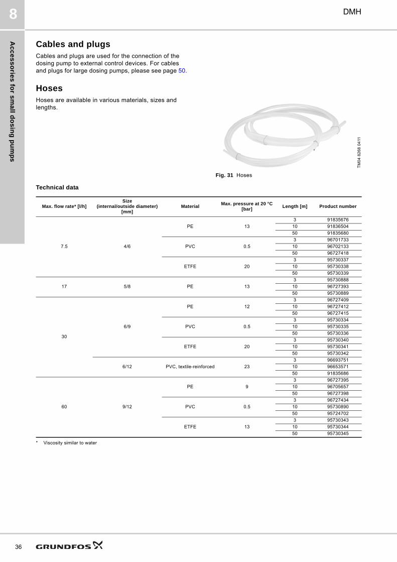
HosesHoses are available in various materials, sizes and lengths.
Fig. 31 Hoses
Technical data
* Viscosity similar to water
TM
04
82
68
04
11
Max. flow rate* [l/h]Size
(internal/outside diameter)[mm]
MaterialMax. pressure at 20 °C
[bar]Length [m] Product number
7.5 4/6
PE 13
3 91835676
10 91836504
50 91835680
PVC 0.5
3 96701733
10 96702133
50 96727418
ETFE 20
3 95730337
10 95730338
50 95730339
17 5/8 PE 13
3 95730888
10 96727393
50 95730889
30
6/9
PE 12
3 96727409
10 96727412
50 96727415
PVC 0.5
3 95730334
10 95730335
50 95730336
ETFE 20
3 95730340
10 95730341
50 95730342
6/12 PVC, textile-reinforced 23
3 96693751
10 96653571
50 91835686
60 9/12
PE 9
3 96727395
10 96705657
50 96727398
PVC 0.5
3 96727434
10 95730890
50 95724702
ETFE 13
3 95730343
10 95730344
50 95730345
Ac
ce
ss
ori
es
fo
r s
ma
ll d
os
ing
pu
mp
s
DMH 8
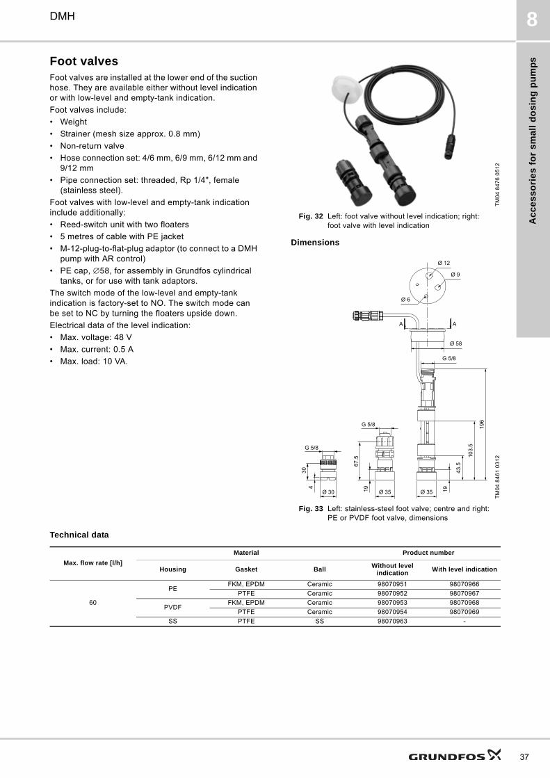
Foot valvesFoot valves are installed at the lower end of the suction hose. They are available either without level indication or with low-level and empty-tank indication.
Foot valves include:
• Weight
• Strainer (mesh size approx. 0.8 mm)
• Non-return valve
• Hose connection set: 4/6 mm, 6/9 mm, 6/12 mm and 9/12 mm
• Pipe connection set: threaded, Rp 1/4", female (stainless steel).
Foot valves with low-level and empty-tank indication include additionally:
• Reed-switch unit with two floaters
• 5 metres of cable with PE jacket
• M-12-plug-to-flat-plug adaptor (to connect to a DMH pump with AR control)
• PE cap, ∅58, for assembly in Grundfos cylindrical tanks, or for use with tank adaptors.
The switch mode of the low-level and empty-tank indication is factory-set to NO. The switch mode can be set to NC by turning the floaters upside down.
Electrical data of the level indication:
• Max. voltage: 48 V
• Max. current: 0.5 A
• Max. load: 10 VA.
Fig. 32 Left: foot valve without level indication; right: foot valve with level indication
Dimensions
Fig. 33 Left: stainless-steel foot valve; centre and right: PE or PVDF foot valve, dimensions
Technical data
TM
04
84
76
05
12
TM
04
84
61
03
12
Max. flow rate [l/h]
Material Product number
Housing Gasket BallWithout level
indicationWith level indication
60
PEFKM, EPDM Ceramic 98070951 98070966
PTFE Ceramic 98070952 98070967
PVDFFKM, EPDM Ceramic 98070953 98070968
PTFE Ceramic 98070954 98070969
SS PTFE SS 98070963 -
37
Ac
ce
ss
orie
s fo
r sm
all d
os
ing
pu
mp
s
38
DMH8
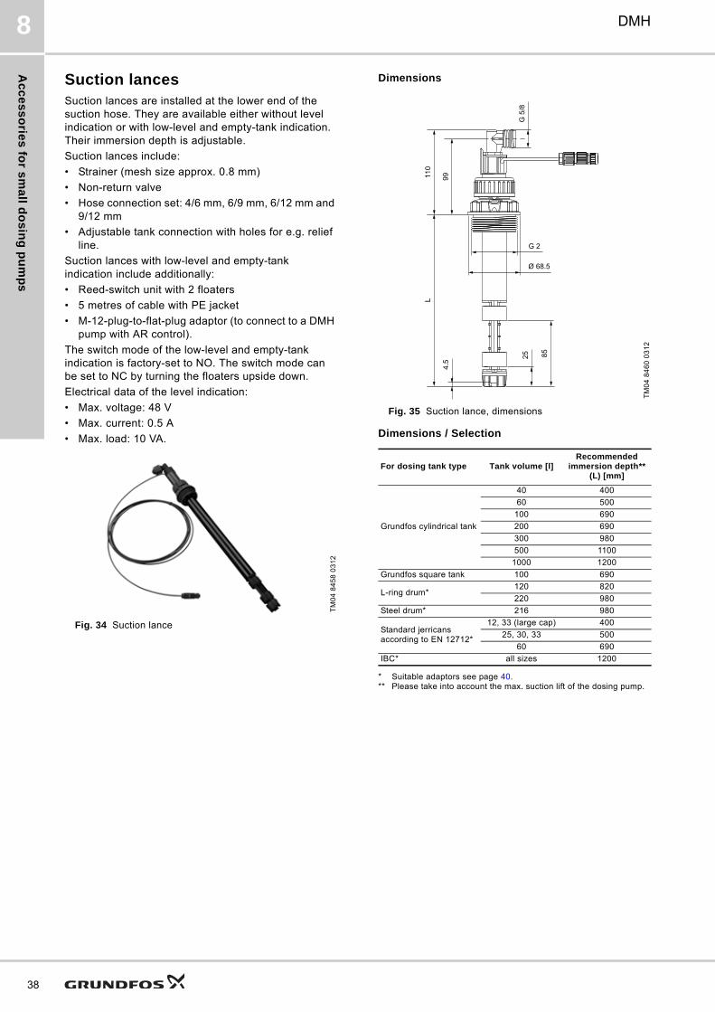
Suction lancesSuction lances are installed at the lower end of the suction hose. They are available either without level indication or with low-level and empty-tank indication. Their immersion depth is adjustable.
Suction lances include:
• Strainer (mesh size approx. 0.8 mm)
• Non-return valve
• Hose connection set: 4/6 mm, 6/9 mm, 6/12 mm and 9/12 mm
• Adjustable tank connection with holes for e.g. relief line.
Suction lances with low-level and empty-tank indication include additionally:
• Reed-switch unit with 2 floaters
• 5 metres of cable with PE jacket
• M-12-plug-to-flat-plug adaptor (to connect to a DMH pump with AR control).
The switch mode of the low-level and empty-tank indication is factory-set to NO. The switch mode can be set to NC by turning the floaters upside down.
Electrical data of the level indication:
• Max. voltage: 48 V
• Max. current: 0.5 A
• Max. load: 10 VA.
Fig. 34 Suction lance
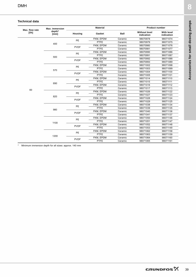
Dimensions
Fig. 35 Suction lance, dimensions
Dimensions / Selection
* Suitable adaptors see page 40.** Please take into account the max. suction lift of the dosing pump.
TM
04
84
58
03
12
TM
04
84
60
03
12
For dosing tank type Tank volume [l]Recommended
immersion depth** (L) [mm]
Grundfos cylindrical tank
40 400
60 500
100 690
200 690
300 980
500 1100
1000 1200
Grundfos square tank 100 690
L-ring drum*120 820
220 980
Steel drum* 216 980
Standard jerricans according to EN 12712*
12, 33 (large cap) 400
25, 30, 33 500
60 690
IBC* all sizes 1200
Ac
ce
ss
ori
es
fo
r s
ma
ll d
os
ing
pu
mp
s
DMH 8
Technical data
* Minimum immersion depth for all sizes: approx. 140 mm
Max. flow rate[l/h]
Max. immersion depth*[mm]
Material Product number
Housing Gasket BallWithout level
indicationWith level indication
60
400
PEFKM, EPDM Ceramic 98070978 98071074
PTFE Ceramic 98070979 98071075
PVDFFKM, EPDM Ceramic 98070980 98071076
PTFE Ceramic 98070981 98071077
500
PEFKM, EPDM Ceramic 98070990 98071086
PTFE Ceramic 98070991 98071087
PVDFFKM, EPDM Ceramic 98070992 98071088
PTFE Ceramic 98070993 98071089
570
PEFKM, EPDM Ceramic 98071002 98071098
PTFE Ceramic 98071003 98071099
PVDFFKM, EPDM Ceramic 98071004 98071100
PTFE Ceramic 98071005 98071101
690
PEFKM, EPDM Ceramic 98071014 98071110
PTFE Ceramic 98071015 98071111
PVDFFKM, EPDM Ceramic 98071016 98071112
PTFE Ceramic 98071017 98071113
820
PEFKM, EPDM Ceramic 98071026 98071122
PTFE Ceramic 98071027 98071123
PVDFFKM, EPDM Ceramic 98071028 98071124
PTFE Ceramic 98071029 98071125
980
PEFKM, EPDM Ceramic 98071038 98071134
PTFE Ceramic 98071039 98071135
PVDFFKM, EPDM Ceramic 98071040 98071136
PTFE Ceramic 98071041 98071137
1100
PEFKM, EPDM Ceramic 98071050 98071146
PTFE Ceramic 98071051 98071147
PVDFFKM, EPDM Ceramic 98071052 98071148
PTFE Ceramic 98071053 98071149
1200
PEFKM, EPDM Ceramic 98071062 98071158
PTFE Ceramic 98071063 98071159
PVDFFKM, EPDM Ceramic 98071064 98071160
PTFE Ceramic 98071065 98071161
39
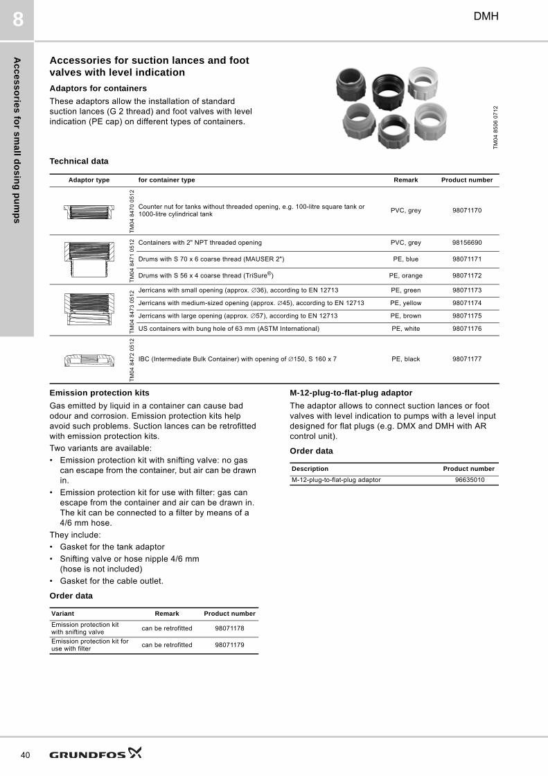
Ac
ce
ss
orie
s fo
r sm
all d
os
ing
pu
mp
s
40
DMH8
Accessories for suction lances and foot valves with level indication
Adaptors for containers
These adaptors allow the installation of standard suction lances (G 2 thread) and foot valves with level indication (PE cap) on different types of containers.
Technical data
Emission protection kits
Gas emitted by liquid in a container can cause bad odour and corrosion. Emission protection kits help avoid such problems. Suction lances can be retrofitted with emission protection kits.
Two variants are available:
• Emission protection kit with snifting valve: no gas can escape from the container, but air can be drawn in.
• Emission protection kit for use with filter: gas can escape from the container and air can be drawn in. The kit can be connected to a filter by means of a 4/6 mm hose.
They include:
• Gasket for the tank adaptor
• Snifting valve or hose nipple 4/6 mm (hose is not included)
• Gasket for the cable outlet.
Order data
M-12-plug-to-flat-plug adaptor
The adaptor allows to connect suction lances or foot valves with level indication to pumps with a level input designed for flat plugs (e.g. DMX and DMH with AR control unit).
Order data
TM
04
85
06
07
12
Adaptor type for container type Remark Product number
TM
04
84
70
05
12
Counter nut for tanks without threaded opening, e.g. 100-litre square tank or 1000-litre cylindrical tank
PVC, grey 98071170
TM
04
84
71
05
12 Containers with 2" NPT threaded opening PVC, grey 98156690
Drums with S 70 x 6 coarse thread (MAUSER 2") PE, blue 98071171
Drums with S 56 x 4 coarse thread (TriSure®) PE, orange 98071172
TM
04
84
73
05
12 Jerricans with small opening (approx. ∅36), according to EN 12713 PE, green 98071173
Jerricans with medium-sized opening (approx. ∅45), according to EN 12713 PE, yellow 98071174
Jerricans with large opening (approx. ∅57), according to EN 12713 PE, brown 98071175
US containers with bung hole of 63 mm (ASTM International) PE, white 98071176
TM
04
84
72
05
12
IBC (Intermediate Bulk Container) with opening of ∅150, S 160 x 7 PE, black 98071177
Variant Remark Product number
Emission protection kit with snifting valve
can be retrofitted 98071178
Emission protection kit for use with filter
can be retrofitted 98071179
Description Product number
M-12-plug-to-flat-plug adaptor 96635010
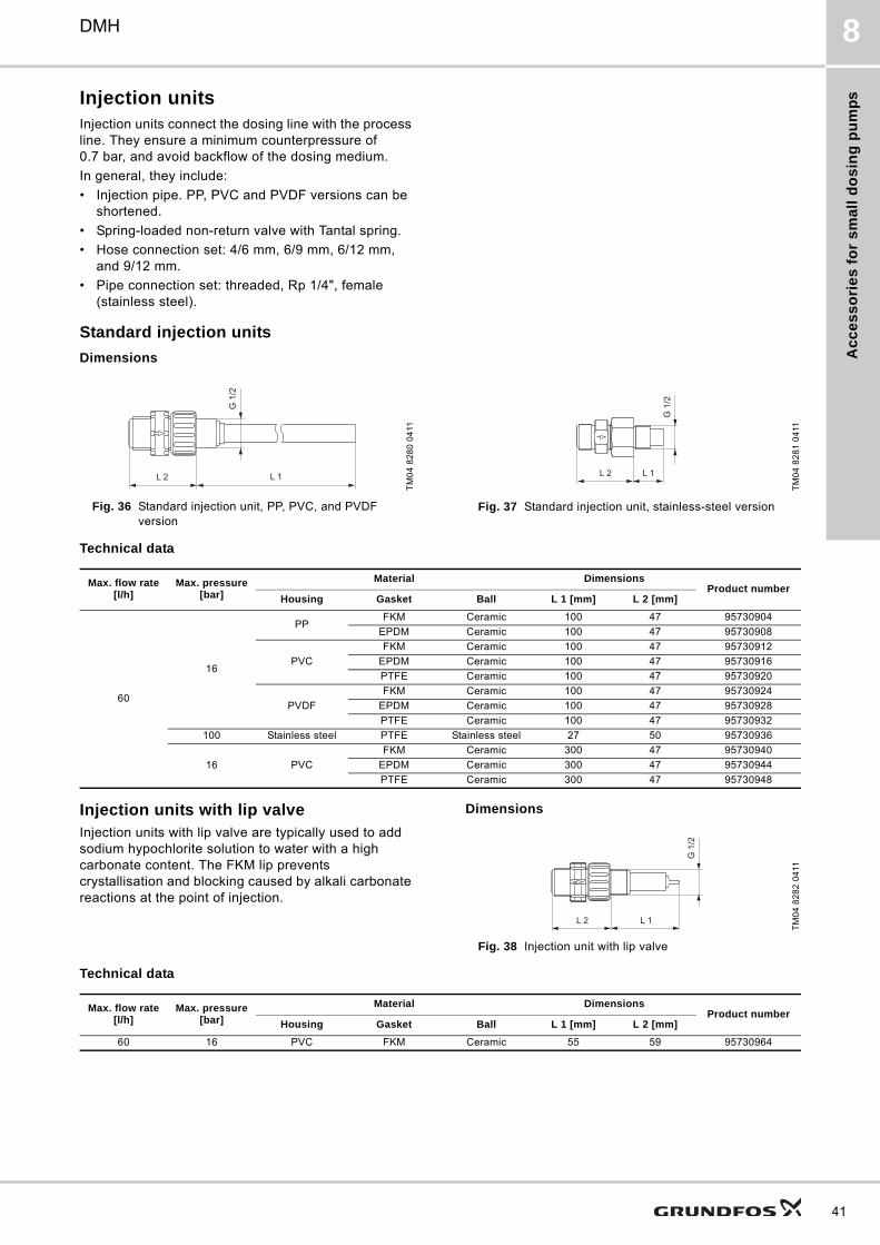
Ac
ce
ss
ori
es
fo
r s
ma
ll d
os
ing
pu
mp
s
DMH 8
Injection unitsInjection units connect the dosing line with the process line. They ensure a minimum counterpressure of 0.7 bar, and avoid backflow of the dosing medium.
In general, they include:
• Injection pipe. PP, PVC and PVDF versions can be shortened.
• Spring-loaded non-return valve with Tantal spring.
• Hose connection set: 4/6 mm, 6/9 mm, 6/12 mm, and 9/12 mm.
• Pipe connection set: threaded, Rp 1/4", female (stainless steel).
Standard injection units
Dimensions
Fig. 36 Standard injection unit, PP, PVC, and PVDF version
Fig. 37 Standard injection unit, stainless-steel version
Technical data
Injection units with lip valveInjection units with lip valve are typically used to add sodium hypochlorite solution to water with a high carbonate content. The FKM lip prevents crystallisation and blocking caused by alkali carbonate reactions at the point of injection.
Dimensions
Fig. 38 Injection unit with lip valve
Technical data
TM
04
82
80
04
11
G 1
/2
L 2 L 1
TM
04
82
81
04
11
G 1
/2
L 1L 2
Max. flow rate [l/h]
Max. pressure [bar]
Material DimensionsProduct number
Housing Gasket Ball L 1 [mm] L 2 [mm]
60
16
PPFKM Ceramic 100 47 95730904
EPDM Ceramic 100 47 95730908
PVC
FKM Ceramic 100 47 95730912
EPDM Ceramic 100 47 95730916
PTFE Ceramic 100 47 95730920
PVDF
FKM Ceramic 100 47 95730924
EPDM Ceramic 100 47 95730928
PTFE Ceramic 100 47 95730932
100 Stainless steel PTFE Stainless steel 27 50 95730936
16 PVC
FKM Ceramic 300 47 95730940
EPDM Ceramic 300 47 95730944
PTFE Ceramic 300 47 95730948
TM
04
82
82
04
11
G 1
/2
L 1L 2
Max. flow rate [l/h]
Max. pressure [bar]
Material DimensionsProduct number
Housing Gasket Ball L 1 [mm] L 2 [mm]
60 16 PVC FKM Ceramic 55 59 95730964
41
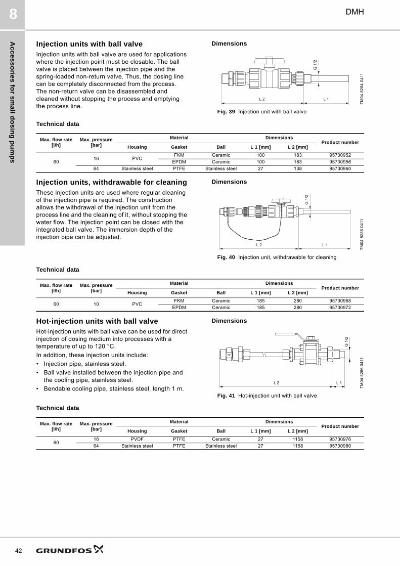
Ac
ce
ss
orie
s fo
r sm
all d
os
ing
pu
mp
s
42
DMH8
Injection units with ball valveInjection units with ball valve are used for applications where the injection point must be closable. The ball valve is placed between the injection pipe and the spring-loaded non-return valve. Thus, the dosing line can be completely disconnected from the process. The non-return valve can be disassembled and cleaned without stopping the process and emptying the process line.
Dimensions
Fig. 39 Injection unit with ball valve
Technical data
Injection units, withdrawable for cleaningThese injection units are used where regular cleaning of the injection pipe is required. The construction allows the withdrawal of the injection unit from the process line and the cleaning of it, without stopping the water flow. The injection point can be closed with the integrated ball valve. The immersion depth of the injection pipe can be adjusted.
Dimensions
Fig. 40 Injection unit, withdrawable for cleaning
Technical data
Hot-injection units with ball valveHot-injection units with ball valve can be used for direct injection of dosing medium into processes with a temperature of up to 120 °C.
In addition, these injection units include:
• Injection pipe, stainless steel.
• Ball valve installed between the injection pipe and the cooling pipe, stainless steel.
• Bendable cooling pipe, stainless steel, length 1 m.
Dimensions
Fig. 41 Hot-injection unit with ball valve
Technical data
TM
04
82
84
04
11
L 1L 2
G 1
/2
Max. flow rate [l/h]
Max. pressure [bar]
Material DimensionsProduct number
Housing Gasket Ball L 1 [mm] L 2 [mm]
6016 PVC
FKM Ceramic 100 183 95730952
EPDM Ceramic 100 183 95730956
64 Stainless steel PTFE Stainless steel 27 138 95730960
TM
04
82
85
04
11
L 1
G 1
/2
L 2
Max. flow rate [l/h]
Max. pressure [bar]
Material DimensionsProduct number
Housing Gasket Ball L 1 [mm] L 2 [mm]
60 10 PVCFKM Ceramic 185 280 95730968
EPDM Ceramic 185 280 95730972
TM
04
82
86
04
11
L 1L 2
G 1
/2
Max. flow rate [l/h]
Max. pressure [bar]
Material DimensionsProduct number
Housing Gasket Ball L 1 [mm] L 2 [mm]
6016 PVDF PTFE Ceramic 27 1158 95730976
64 Stainless steel PTFE Stainless steel 27 1158 95730980
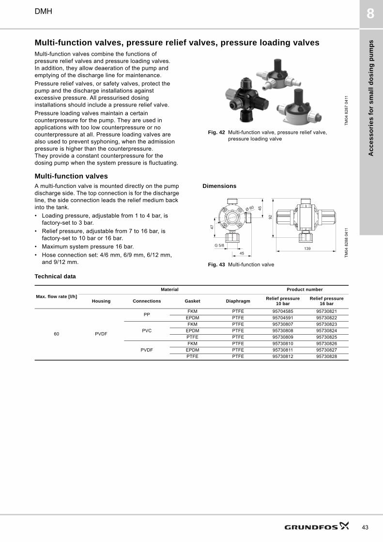
Ac
ce
ss
ori
es
fo
r s
ma
ll d
os
ing
pu
mp
s
DMH 8
Multi-function valves, pressure relief valves, pressure loading valvesMulti-function valves combine the functions of pressure relief valves and pressure loading valves. In addition, they allow deaeration of the pump and emptying of the discharge line for maintenance.
Pressure relief valves, or safety valves, protect the pump and the discharge installations against excessive pressure. All pressurised dosing installations should include a pressure relief valve.
Pressure loading valves maintain a certain counterpressure for the pump. They are used in applications with too low counterpressure or no counterpressure at all. Pressure loading valves are also used to prevent syphoning, when the admission pressure is higher than the counterpressure. They provide a constant counterpressure for the dosing pump when the system pressure is fluctuating.
Fig. 42 Multi-function valve, pressure relief valve, pressure loading valve
Multi-function valvesA multi-function valve is mounted directly on the pump discharge side. The top connection is for the discharge line, the side connection leads the relief medium back into the tank.
• Loading pressure, adjustable from 1 to 4 bar, is factory-set to 3 bar.
• Relief pressure, adjustable from 7 to 16 bar, is factory-set to 10 bar or 16 bar.
• Maximum system pressure 16 bar.
• Hose connection set: 4/6 mm, 6/9 mm, 6/12 mm, and 9/12 mm.
Dimensions
Fig. 43 Multi-function valve
Technical data
TM
04
82
87
04
11T
M0
4 8
28
8 0
411
92
139
45
47
45
G 5/8
Ø 60
Max. flow rate [l/h]
Material Product number
Housing Connections Gasket DiaphragmRelief pressure
10 barRelief pressure
16 bar
60 PVDF
PPFKM PTFE 95704585 95730821
EPDM PTFE 95704591 95730822
PVC
FKM PTFE 95730807 95730823
EPDM PTFE 95730808 95730824
PTFE PTFE 95730809 95730825
PVDF
FKM PTFE 95730810 95730826
EPDM PTFE 95730811 95730827
PTFE PTFE 95730812 95730828
43
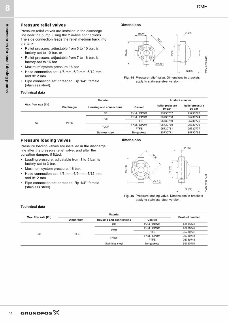
Ac
ce
ss
orie
s fo
r sm
all d
os
ing
pu
mp
s
44
DMH8
Pressure relief valvesPressure relief valves are installed in the discharge line near the pump, using the 2 in-line connections. The side connection leads the relief medium back into the tank.
• Relief pressure, adjustable from 5 to 10 bar, is factory-set to 10 bar, or
• Relief pressure, adjustable from 7 to 16 bar, is factory-set to 16 bar.
• Maximum system pressure 16 bar.
• Hose connection set: 4/6 mm, 6/9 mm, 6/12 mm, and 9/12 mm.
• Pipe connection set: threaded, Rp 1/4", female (stainless steel).
Dimensions
Fig. 44 Pressure relief valve. Dimensions in brackets apply to stainless-steel version.
Technical data
Pressure loading valvesPressure loading valves are installed in the discharge line after the pressure relief valve, and after the pulsation damper, if fitted.
• Loading pressure, adjustable from 1 to 5 bar, is factory-set to 3 bar.
• Maximum system pressure: 16 bar.
• Hose connection set: 4/6 mm, 6/9 mm, 6/12 mm, and 9/12 mm.
• Pipe connection set: threaded, Rp 1/4", female (stainless steel).
Dimensions
Fig. 45 Pressure loading valve. Dimensions in brackets apply to stainless-steel version.
Technical dataT
M0
4 8
29
0 0
411
Ø4.5(-)
48(20)
96(4
0)
78 (-)
21(22)
82(82)
68(6
8)
Max. flow rate [l/h]
Material Product number
Diaphragm Housing and connections GasketRelief pressure
10 barRelief pressure
16 bar
60 PTFE
PP FKM / EPDM 95730757 95730773
PVCFKM / EPDM 95730758 95730774
PTFE 95730759 95730775
PVDFFKM / EPDM 95730760 95730776
PTFE 95730761 95730777
Stainless steel No gaskets 95730771 95730783
TM
04
82
92
04
11
21 (22)
68 (6
8)
82 (82)
Ø4.5 (-)
78 (-)
96 (4
0)
Max. flow rate [l/h]Material
Product numberDiaphragm Housing and connections Gasket
60 PTFE
PP FKM / EPDM 95730741
PVCFKM / EPDM 95730742
PTFE 95730743
PVDFFKM / EPDM 95730744
PTFE 95730745
Stainless steel No gaskets 95730751
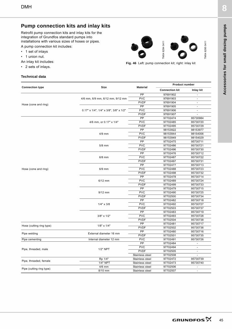
Ac
ce
ss
ori
es
fo
r s
ma
ll d
os
ing
pu
mp
s
DMH 8
Pump connection kits and inlay kitsRetrofit pump connection kits and inlay kits for the integration of Grundfos standard pumps into installations with various sizes of hoses or pipes.
A pump connection kit includes:
• 1 set of inlays
• 1 union nut.
An inlay kit includes:
• 2 sets of inlays.Fig. 46 Left: pump connection kit; right: inlay kit
Technical data
TM
04
82
94
04
11
TM
04
82
95
04
11
Connection type Size MaterialProduct number
Connection kit Inlay kit
Hose (cone and ring)
4/6 mm, 6/9 mm, 6/12 mm, 9/12 mm
PP 97691902 -
PVC 97691903 -
PVDF 97691904 -
0.17" x 1/4", 1/4" x 3/8", 3/8" x 1/2"
PP 97691905 -
PVC 97691906 -
PVDF 97691907 -
Hose (cone and ring)
4/6 mm, or 0.17" x 1/4"
PP 97702474 95730984
PVC 97702485 95730720
PVDF 97702495 95730729
4/9 mm
PP 98153922 98153977
PVC 98153944 98154006
PVDF 98153949 98154029
5/8 mm
PP 97702475 95730711
PVC 97702486 95730721
PVDF 97702496 95730730
6/8 mm
PP 97702476 95730712
PVC 97702487 95730722
PVDF 97702497 95730731
6/9 mm
PP 97702477 95730713
PVC 97702488 95730723
PVDF 97702498 95730732
6/12 mm
PP 97702478 95730714
PVC 97702489 95730724
PVDF 97702499 95730733
9/12 mm
PP 97702479 95730715
PVC 97702490 95730725
PVDF 97702500 95730734
1/4" x 3/8
PP 97702482 95730718
PVC 97702492 95730727
PVDF 97702503 95730737
3/8" x 1/2"
PP 97702483 95730719
PVC 97702493 95730728
PVDF 97702504 95730738
Hose (cutting ring type) 1/8" x 1/4"PP 97702481 95730717
PVDF 97702502 95730736
Pipe welding External diameter 16 mmPP 97702480 95730716
PVDF 97702501 95730735
Pipe cementing Internal diameter 12 mm PVC 97702491 95730726
Pipe, threaded, male 1/2" NPT
PP 97702484 -
PVC 97702494 -
PVDF 97702505 -
Stainless steel 97702508 -
Pipe, threaded, femaleRp 1/4" Stainless steel 97702472 95730739
1/4" NPT Stainless steel 97702473 95730740
Pipe (cutting ring type)4/6 mm Stainless steel 97702506 -
8/10 mm Stainless steel 97702507 -
45
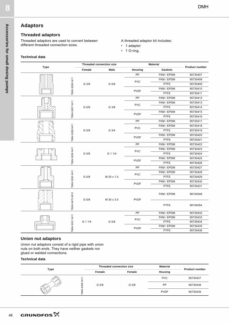
Ac
ce
ss
orie
s fo
r sm
all d
os
ing
pu
mp
s
46
DMH8
Adaptors
Threaded adaptorsThreaded adaptors are used to convert between different threaded connection sizes.
A threaded adaptor kit includes:
• 1 adaptor
• 1 O-ring.
Technical data
Union nut adaptorsUnion nut adaptors consist of a rigid pipe with union nuts on both ends. They have neither gaskets nor glued or welded connections.
Technical data
TypeThreaded connection size Material
Product numberFemale Male Housing Gaskets
TM
04
82
96
04
11
G 3/8 G 5/8
PP FKM / EPDM 95730407
PVCFKM / EPDM 95730408
PTFE 95730409
PVDFFKM / EPDM 95730410
PTFE 95730411
TM
04
82
97
04
11
G 5/8 G 3/8
PP FKM / EPDM 95730412
PVCFKM / EPDM 95730413
PTFE 95730414
PVDFFKM / EPDM 95730415
PTFE 95730416
TM
04
82
98
04
11
G 5/8 G 3/4
PP FKM / EPDM 95730417
PVCFKM / EPDM 95730418
PTFE 95730419
PVDFFKM / EPDM 95730420
PTFE 95730421
TM
04
82
99
04
11
G 5/8 G 1 1/4
PP FKM / EPDM 95730422
PVCFKM / EPDM 95730423
PTFE 95730424
PVDFFKM / EPDM 95730425
PTFE 95730426
TM
04
83
00
04
11
G 5/8 M 20 x 1.5
PP FKM / EPDM 95730427
PVCFKM / EPDM 95730428
PTFE 95730429
PVDFFKM / EPDM 95730430
PTFE 95730431
TM
04
84
75
06
12
G 5/8 M 30 x 3.5 PVDF
FKM / EPDM 98154048
PTFE 98154054
TM
04
83
01
04
11
G 1 1/4 G 5/8
PP FKM / EPDM 95730432
PVCFKM / EPDM 95730433
PTFE 95730434
PVDFFKM / EPDM 95730435
PTFE 95730436
TypeThreaded connection size Material
Product numberFemale Female Housing
TM
04
83
06
04
11
G 5/8 G 5/8
PVC 95730437
PP 95730438
PVDF 95730439
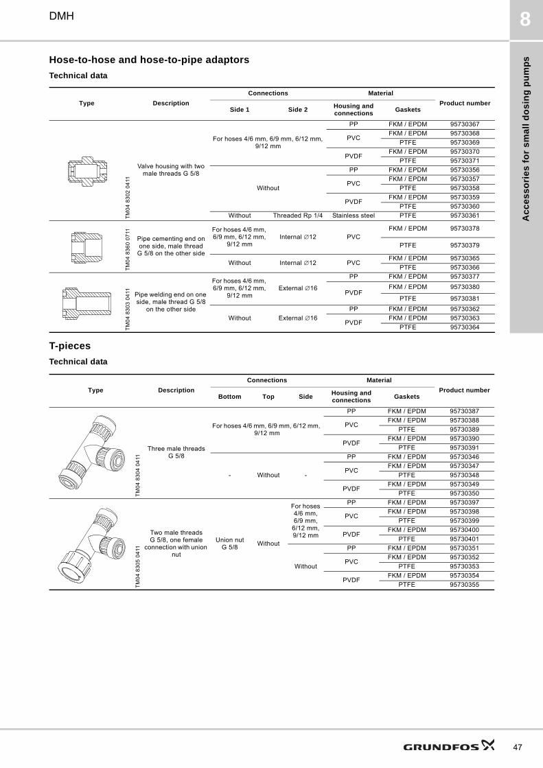
Ac
ce
ss
ori
es
fo
r s
ma
ll d
os
ing
pu
mp
s
DMH 8
Hose-to-hose and hose-to-pipe adaptors
Technical data
T-pieces
Technical data
Type Description
Connections Material
Product numberSide 1 Side 2
Housing and connections
Gaskets
TM
04
83
02
04
11
Valve housing with two male threads G 5/8
For hoses 4/6 mm, 6/9 mm, 6/12 mm, 9/12 mm
PP FKM / EPDM 95730367
PVCFKM / EPDM 95730368
PTFE 95730369
PVDFFKM / EPDM 95730370
PTFE 95730371
Without
PP FKM / EPDM 95730356
PVCFKM / EPDM 95730357
PTFE 95730358
PVDFFKM / EPDM 95730359
PTFE 95730360
Without Threaded Rp 1/4 Stainless steel PTFE 95730361
TM
04
83
60
07
11
Pipe cementing end on one side, male thread
G 5/8 on the other side
For hoses 4/6 mm, 6/9 mm, 6/12 mm,
9/12 mmInternal ∅12 PVC
FKM / EPDM 95730378
PTFE 95730379
Without Internal ∅12 PVCFKM / EPDM 95730365
PTFE 95730366
TM
04
83
03
04
11 Pipe welding end on one side, male thread G 5/8
on the other side
For hoses 4/6 mm, 6/9 mm, 6/12 mm,
9/12 mmExternal ∅16
PP FKM / EPDM 95730377
PVDFFKM / EPDM 95730380
PTFE 95730381
Without External ∅16
PP FKM / EPDM 95730362
PVDFFKM / EPDM 95730363
PTFE 95730364
Type Description
Connections Material
Product numberBottom Top Side
Housing and connections
Gaskets
TM
04
83
04
04
11
Three male threads G 5/8
For hoses 4/6 mm, 6/9 mm, 6/12 mm, 9/12 mm
PP FKM / EPDM 95730387
PVCFKM / EPDM 95730388
PTFE 95730389
PVDFFKM / EPDM 95730390
PTFE 95730391
- Without -
PP FKM / EPDM 95730346
PVCFKM / EPDM 95730347
PTFE 95730348
PVDFFKM / EPDM 95730349
PTFE 95730350
TM
04
83
05
04
11
Two male threads G 5/8, one female
connection with union nut
Union nut G 5/8
Without
For hoses 4/6 mm, 6/9 mm,
6/12 mm, 9/12 mm
PP FKM / EPDM 95730397
PVCFKM / EPDM 95730398
PTFE 95730399
PVDFFKM / EPDM 95730400
PTFE 95730401
Without
PP FKM / EPDM 95730351
PVCFKM / EPDM 95730352
PTFE 95730353
PVDFFKM / EPDM 95730354
PTFE 95730355
47
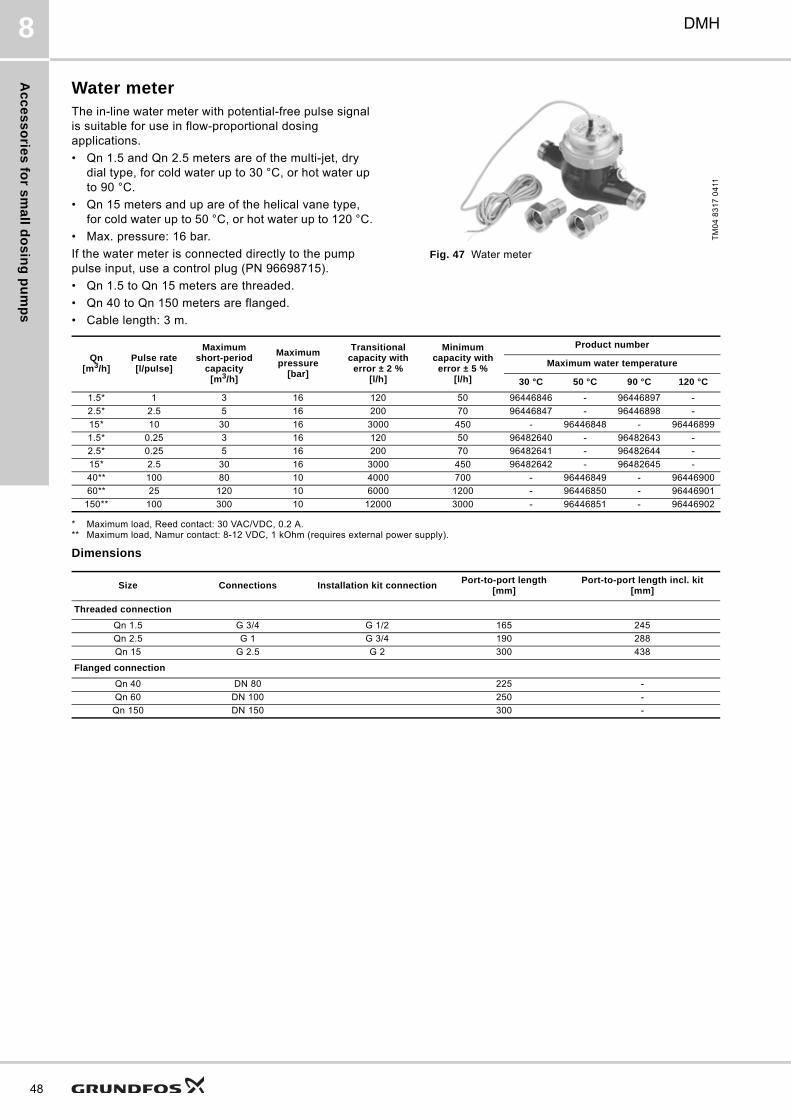
Ac
ce
ss
orie
s fo
r sm
all d
os
ing
pu
mp
s
48
DMH8
Water meterThe in-line water meter with potential-free pulse signal is suitable for use in flow-proportional dosing applications.
• Qn 1.5 and Qn 2.5 meters are of the multi-jet, dry dial type, for cold water up to 30 °C, or hot water up to 90 °C.
• Qn 15 meters and up are of the helical vane type, for cold water up to 50 °C, or hot water up to 120 °C.
• Max. pressure: 16 bar.
If the water meter is connected directly to the pump pulse input, use a control plug (PN 96698715).
• Qn 1.5 to Qn 15 meters are threaded.
• Qn 40 to Qn 150 meters are flanged.
• Cable length: 3 m.
Fig. 47 Water meter
* Maximum load, Reed contact: 30 VAC/VDC, 0.2 A.** Maximum load, Namur contact: 8-12 VDC, 1 kOhm (requires external power supply).
Dimensions
TM
04
83
17
04
11
Qn[m3/h]
Pulse rate[l/pulse]
Maximum short-period
capacity[m3/h]
Maximum pressure
[bar]
Transitional capacity with
error ± 2 %[l/h]
Minimum capacity with
error ± 5 %[l/h]
Product number
Maximum water temperature
30 °C 50 °C 90 °C 120 °C
1.5* 1 3 16 120 50 96446846 - 96446897 -
2.5* 2.5 5 16 200 70 96446847 - 96446898 -
15* 10 30 16 3000 450 - 96446848 - 96446899
1.5* 0.25 3 16 120 50 96482640 - 96482643 -
2.5* 0.25 5 16 200 70 96482641 - 96482644 -
15* 2.5 30 16 3000 450 96482642 - 96482645 -
40** 100 80 10 4000 700 - 96446849 - 96446900
60** 25 120 10 6000 1200 - 96446850 - 96446901
150** 100 300 10 12000 3000 - 96446851 - 96446902
Size Connections Installation kit connectionPort-to-port length
[mm]Port-to-port length incl. kit
[mm]
Threaded connection
Qn 1.5 G 3/4 G 1/2 165 245
Qn 2.5 G 1 G 3/4 190 288
Qn 15 G 2.5 G 2 300 438
Flanged connection
Qn 40 DN 80 225 -
Qn 60 DN 100 250 -
Qn 150 DN 150 300 -
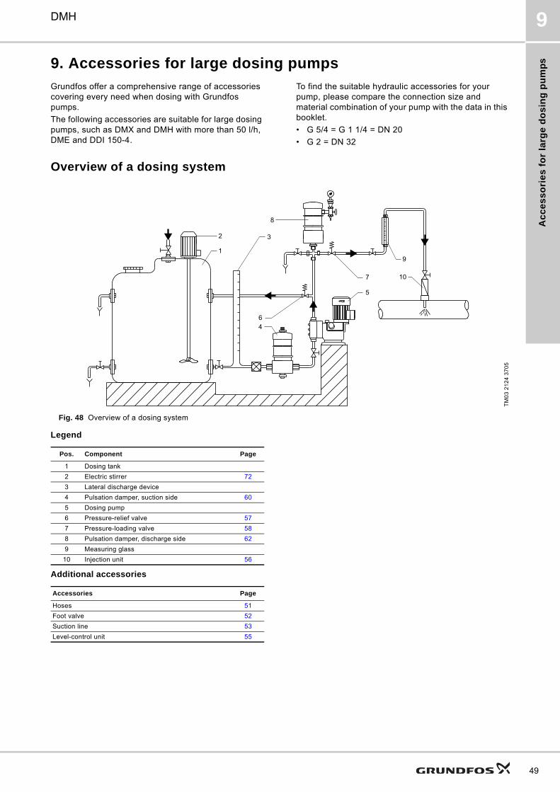
Ac
ce
ss
ori
es
fo
r la
rge
do
sin
g p
um
ps
DMH 9
9. Accessories for large dosing pumps
Grundfos offer a comprehensive range of accessories covering every need when dosing with Grundfos pumps.
The following accessories are suitable for large dosing pumps, such as DMX and DMH with more than 50 l/h, DME and DDI 150-4.
To find the suitable hydraulic accessories for your pump, please compare the connection size and material combination of your pump with the data in this booklet.
• G 5/4 = G 1 1/4 = DN 20
• G 2 = DN 32
Overview of a dosing system
Fig. 48 Overview of a dosing system
Legend
Additional accessories
TM
03
21
24
37
05
2
1
8
3
64
7
5
9
10
Pos. Component Page
1 Dosing tank
2 Electric stirrer 72
3 Lateral discharge device
4 Pulsation damper, suction side 60
5 Dosing pump
6 Pressure-relief valve 57
7 Pressure-loading valve 58
8 Pulsation damper, discharge side 62
9 Measuring glass
10 Injection unit 56
Accessories Page
Hoses 51
Foot valve 52
Suction line 53
Level-control unit 55
49
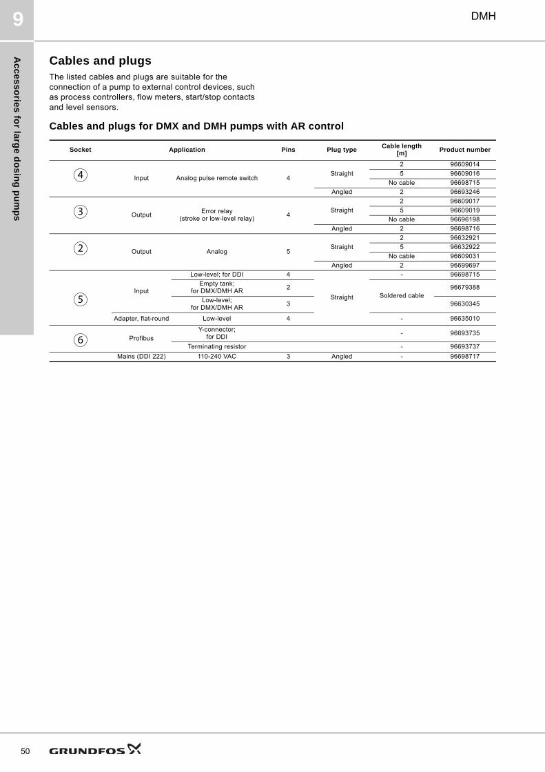
Ac
ce
ss
orie
s fo
r larg
e d
os
ing
pu
mp
s
50
DMH9
Cables and plugsThe listed cables and plugs are suitable for the connection of a pump to external control devices, such as process controllers, flow meters, start/stop contacts and level sensors.
Cables and plugs for DMX and DMH pumps with AR control
Socket Application Pins Plug typeCable length
[m]Product number
Input Analog pulse remote switch 4Straight
2 96609014
5 96609016
No cable 96698715
Angled 2 96693246
OutputError relay
(stroke or low-level relay)4
Straight
2 96609017
5 96609019
No cable 96696198
Angled 2 96698716
Output Analog 5Straight
2 96632921
5 96632922
No cable 96609031
Angled 2 96699697
Input
Low-level; for DDI 4
Straight
- 96698715
Empty tank; for DMX/DMH AR
2Soldered cable
96679388
Low-level; for DMX/DMH AR
3 96630345
Adapter, flat-round Low-level 4 - 96635010
ProfibusY-connector;
for DDI - 96693735
Terminating resistor - 96693737
Mains (DDI 222) 110-240 VAC 3 Angled - 96698717
4
3
2
5
6
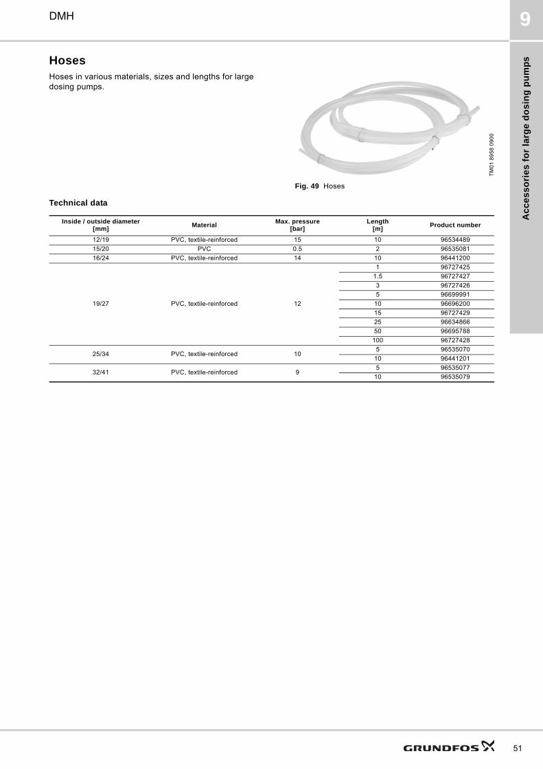
Ac
ce
ss
ori
es
fo
r la
rge
do
sin
g p
um
ps
DMH 9
HosesHoses in various materials, sizes and lengths for large dosing pumps.
Fig. 49 Hoses
Technical data
TM
01
89
58
09
00
Inside / outside diameter[mm]
MaterialMax. pressure
[bar]Length
[m]Product number
12/19 PVC, textile-reinforced 15 10 96534489
15/20 PVC 0.5 2 96535081
16/24 PVC, textile-reinforced 14 10 96441200
19/27 PVC, textile-reinforced 12
1 96727425
1.5 96727427
3 96727426
5 96699991
10 96696200
15 96727429
25 96634866
50 96695788
100 96727428
25/34 PVC, textile-reinforced 105 96535070
10 96441201
32/41 PVC, textile-reinforced 95 96535077
10 96535079
51
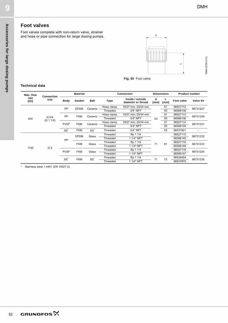
Ac
ce
ss
orie
s fo
r larg
e d
os
ing
pu
mp
s
52
DMH9
Foot valvesFoot valves complete with non-return valve, strainer and hose or pipe connection for large dosing pumps.
Fig. 50 Foot valve
Technical data
* Stainless steel 1.4401 (EN 10027-2)
TM
04
87
09
511
2
d
L
Max. flow rate[l/h]
Connection size
Material Connection Dimensions Product number
Body Gasket Ball TypeInside / outside
diameter or threadd
[mm]L
[mm]Foot valve Valve kit
400G 5/4
(G 1 1/4)
PP EPDM CeramicHose clamp 19/27 mm, 25/34 mm
53
51 9652711296731227
Threaded 3/4" NPT 55 96566136
PP FKM CeramicHose clamp 19/27 mm, 25/34 mm 51 96527113
96731229Threaded 3/4" NPT 55 96566138
PVDF FKM CeramicHose clamp 19/27 mm, 25/34 mm 51 96527114
96731231Threaded 3/4" NPT 55 96566139
SS* FKM SS* Threaded 3/4" NPT 55 96537921 -
1150 G 2
PP
EPDM GlassThreaded Rp 1 1/4
71 81
9652711596731232
Threaded 1 1/4" NPT 96566145
FKM GlassThreaded Rp 1 1/4 96527116
96731233Threaded 1 1/4" NPT 96566146
PVDF FKM GlassThreaded Rp 1 1/4 96527118
96731234Threaded 1 1/4" NPT 96566147
SS* FKM SS* Threaded Rp 1 1/471 73
9653445496731235
Threaded 1 1/4" NPT 96537970
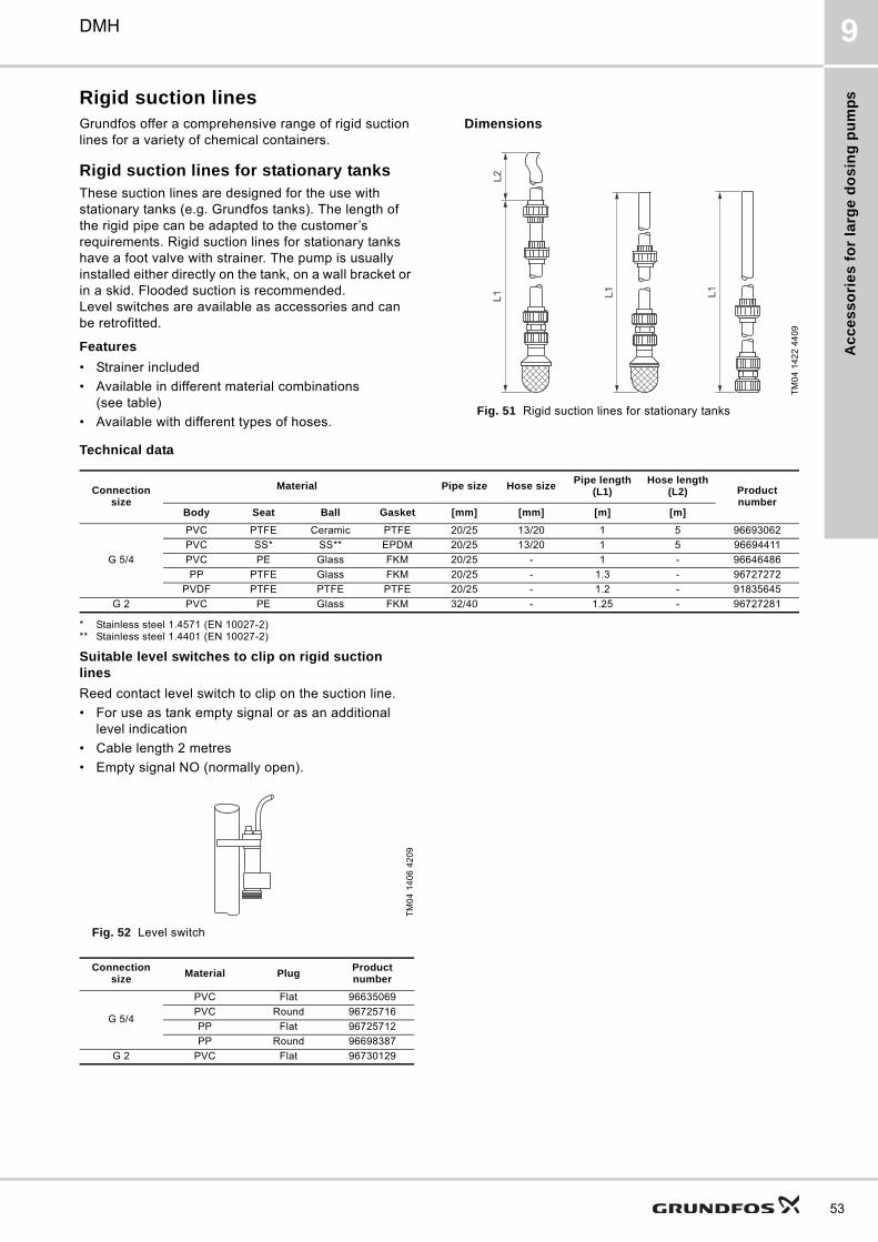
Ac
ce
ss
ori
es
fo
r la
rge
do
sin
g p
um
ps
DMH 9
Rigid suction linesGrundfos offer a comprehensive range of rigid suction lines for a variety of chemical containers.
Rigid suction lines for stationary tanksThese suction lines are designed for the use with stationary tanks (e.g. Grundfos tanks). The length of the rigid pipe can be adapted to the customer’s requirements. Rigid suction lines for stationary tanks have a foot valve with strainer. The pump is usually installed either directly on the tank, on a wall bracket or in a skid. Flooded suction is recommended. Level switches are available as accessories and can be retrofitted.
Features
• Strainer included
• Available in different material combinations (see table)
• Available with different types of hoses.
Dimensions
Fig. 51 Rigid suction lines for stationary tanks
Technical data
* Stainless steel 1.4571 (EN 10027-2)** Stainless steel 1.4401 (EN 10027-2)
Suitable level switches to clip on rigid suction lines
Reed contact level switch to clip on the suction line.
• For use as tank empty signal or as an additional level indication
• Cable length 2 metres
• Empty signal NO (normally open).
Fig. 52 Level switch
TM
04
14
22
44
09
L2L1 L1 L1
Connection size
Material Pipe size Hose sizePipe length
(L1)Hose length
(L2) Product number
Body Seat Ball Gasket [mm] [mm] [m] [m]
G 5/4
PVC PTFE Ceramic PTFE 20/25 13/20 1 5 96693062
PVC SS* SS** EPDM 20/25 13/20 1 5 96694411
PVC PE Glass FKM 20/25 - 1 - 96646486
PP PTFE Glass FKM 20/25 - 1.3 - 96727272
PVDF PTFE PTFE PTFE 20/25 - 1.2 - 91835645
G 2 PVC PE Glass FKM 32/40 - 1.25 - 96727281
TM
04
14
06
42
09
Connection size
Material PlugProduct number
G 5/4
PVC Flat 96635069
PVC Round 96725716
PP Flat 96725712
PP Round 96698387
G 2 PVC Flat 96730129
53
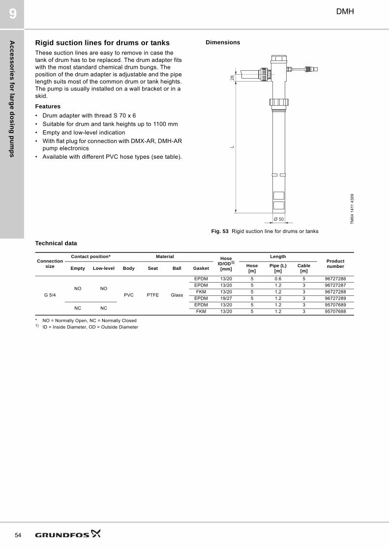
Ac
ce
ss
orie
s fo
r larg
e d
os
ing
pu
mp
s
54
DMH9
Rigid suction lines for drums or tanksThese suction lines are easy to remove in case the tank of drum has to be replaced. The drum adapter fits with the most standard chemical drum bungs. The position of the drum adapter is adjustable and the pipe length suits most of the common drum or tank heights. The pump is usually installed on a wall bracket or in a skid.
Features
• Drum adapter with thread S 70 x 6
• Suitable for drum and tank heights up to 1100 mm
• Empty and low-level indication
• With flat plug for connection with DMX-AR, DMH-AR pump electronics
• Available with different PVC hose types (see table).
Dimensions
Fig. 53 Rigid suction line for drums or tanks
Technical data
* NO = Normally Open, NC = Normally Closed1) ID = Inside Diameter, OD = Outside Diameter
TM
04
14
11 4
30
9
Ø 50
L28
Connection size
Contact position* Material HoseID/OD1)
[mm]
LengthProduct numberEmpty Low-level Body Seat Ball Gasket
Hose[m]
Pipe (L)[m]
Cable[m]
G 5/4
NO NO
PVC PTFE Glass
EPDM 13/20 5 0.6 5 96727286
EPDM 13/20 5 1.2 3 96727287
FKM 13/20 5 1.2 3 96727288
EPDM 19/27 5 1.2 3 96727289
NC NCEPDM 13/20 5 1.2 3 95707689
FKM 13/20 5 1.2 3 95707688
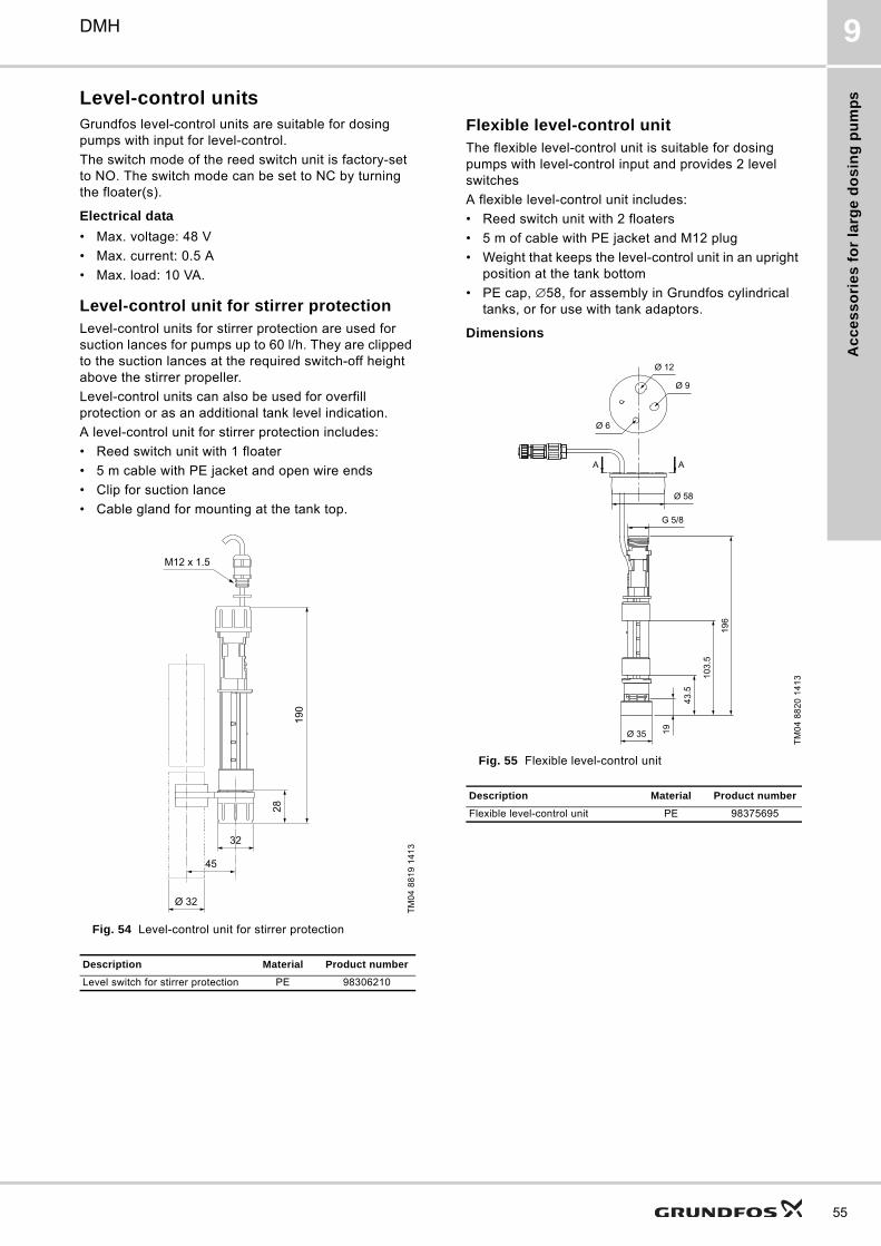
Ac
ce
ss
ori
es
fo
r la
rge
do
sin
g p
um
ps
DMH 9
Level-control unitsGrundfos level-control units are suitable for dosing pumps with input for level-control.
The switch mode of the reed switch unit is factory-set to NO. The switch mode can be set to NC by turning the floater(s).
Electrical data
• Max. voltage: 48 V
• Max. current: 0.5 A
• Max. load: 10 VA.
Level-control unit for stirrer protectionLevel-control units for stirrer protection are used for suction lances for pumps up to 60 l/h. They are clipped to the suction lances at the required switch-off height above the stirrer propeller.
Level-control units can also be used for overfill protection or as an additional tank level indication.
A level-control unit for stirrer protection includes:
• Reed switch unit with 1 floater
• 5 m cable with PE jacket and open wire ends
• Clip for suction lance
• Cable gland for mounting at the tank top.
Fig. 54 Level-control unit for stirrer protection
Flexible level-control unitThe flexible level-control unit is suitable for dosing pumps with level-control input and provides 2 level switches
A flexible level-control unit includes:
• Reed switch unit with 2 floaters
• 5 m of cable with PE jacket and M12 plug
• Weight that keeps the level-control unit in an upright position at the tank bottom
• PE cap, ∅58, for assembly in Grundfos cylindrical tanks, or for use with tank adaptors.
Dimensions
Fig. 55 Flexible level-control unit
TM
04
88
19
14
13
Description Material Product number
Level switch for stirrer protection PE 98306210
Ø 32
45
32
28
190
M12 x 1.5
TM
04
88
20
14
13
Description Material Product number
Flexible level-control unit PE 98375695
55
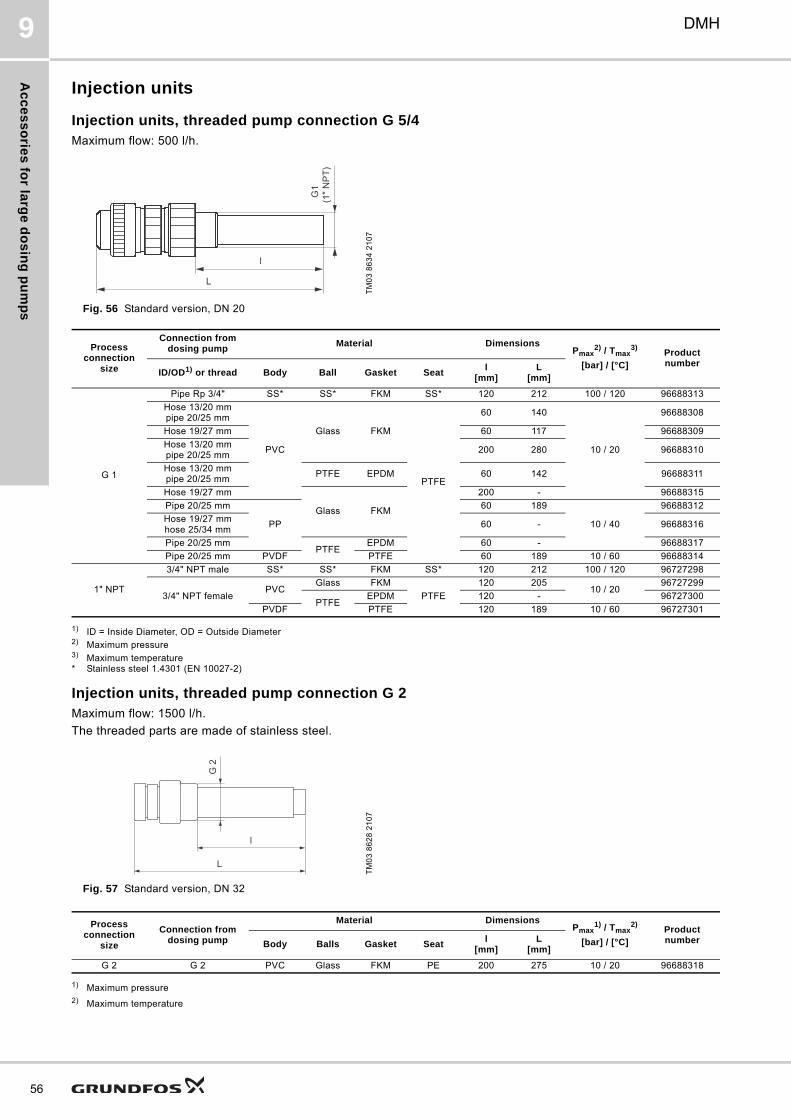
Ac
ce
ss
orie
s fo
r larg
e d
os
ing
pu
mp
s
56
DMH9
Injection units
Injection units, threaded pump connection G 5/4Maximum flow: 500 l/h.
Fig. 56 Standard version, DN 20
1) ID = Inside Diameter, OD = Outside Diameter2) Maximum pressure3) Maximum temperature* Stainless steel 1.4301 (EN 10027-2)
Injection units, threaded pump connection G 2Maximum flow: 1500 l/h.
The threaded parts are made of stainless steel.
Fig. 57 Standard version, DN 32
1) Maximum pressure2) Maximum temperature
TM
03
86
34
21
07
L
l
G1
(1" N
PT)
Process connection
size
Connection from dosing pump
Material DimensionsPmax
2) / Tmax3)
[bar] / [°C]Product number
ID/OD1) or thread Body Ball Gasket Seatl
[mm]L
[mm]
G 1
Pipe Rp 3/4" SS* SS* FKM SS* 120 212 100 / 120 96688313
Hose 13/20 mmpipe 20/25 mm
PVC
Glass FKM
PTFE
60 140
10 / 20
96688308
Hose 19/27 mm 60 117 96688309
Hose 13/20 mmpipe 20/25 mm
200 280 96688310
Hose 13/20 mmpipe 20/25 mm
PTFE EPDM 60 142 96688311
Hose 19/27 mm
Glass FKM
200 - 96688315
Pipe 20/25 mm
PP
60 189
10 / 40
96688312
Hose 19/27 mmhose 25/34 mm
60 - 96688316
Pipe 20/25 mmPTFE
EPDM 60 - 96688317
Pipe 20/25 mm PVDF PTFE 60 189 10 / 60 96688314
1" NPT
3/4" NPT male SS* SS* FKM SS* 120 212 100 / 120 96727298
3/4" NPT femalePVC
Glass FKM
PTFE
120 20510 / 20
96727299
PTFEEPDM 120 - 96727300
PVDF PTFE 120 189 10 / 60 96727301
TM
03
86
28
21
07
Process connection
size
Connection from dosing pump
Material DimensionsPmax
1) / Tmax2)
[bar] / [°C]Product numberBody Balls Gasket Seat
l[mm]
L[mm]
G 2 G 2 PVC Glass FKM PE 200 275 10 / 20 96688318
L
l
G 2
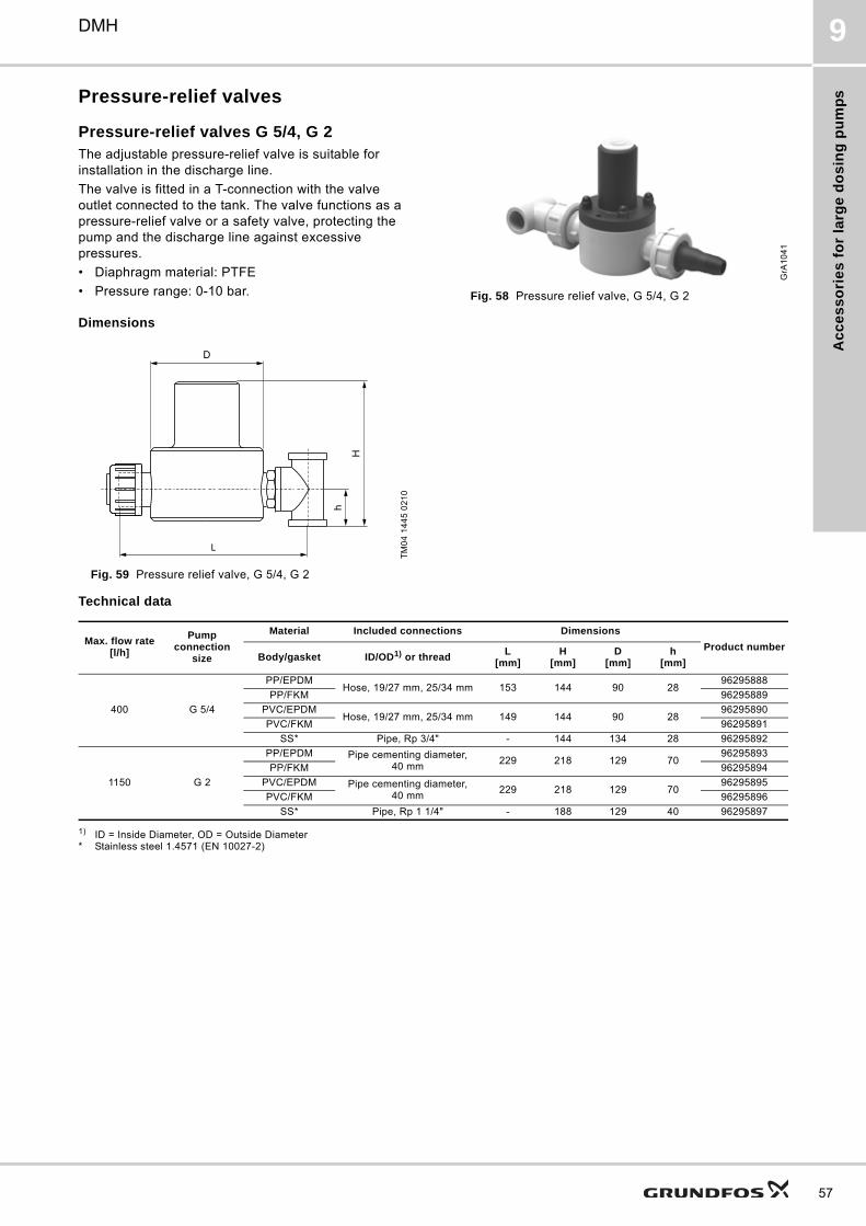
Ac
ce
ss
ori
es
fo
r la
rge
do
sin
g p
um
ps
DMH 9
Pressure-relief valves
Pressure-relief valves G 5/4, G 2The adjustable pressure-relief valve is suitable for installation in the discharge line.
The valve is fitted in a T-connection with the valve outlet connected to the tank. The valve functions as a pressure-relief valve or a safety valve, protecting the pump and the discharge line against excessive pressures.
• Diaphragm material: PTFE
• Pressure range: 0-10 bar. Fig. 58 Pressure relief valve, G 5/4, G 2
Dimensions
Fig. 59 Pressure relief valve, G 5/4, G 2
Technical data
1) ID = Inside Diameter, OD = Outside Diameter* Stainless steel 1.4571 (EN 10027-2)
GrA
10
41
TM
04
14
45
02
10
DH
h
L
Max. flow rate[l/h]
Pump connection
size
Material Included connections Dimensions
Product numberBody/gasket ID/OD1) or thread
L[mm]
H[mm]
D[mm]
h[mm]
400 G 5/4
PP/EPDMHose, 19/27 mm, 25/34 mm 153 144 90 28
96295888
PP/FKM 96295889
PVC/EPDMHose, 19/27 mm, 25/34 mm 149 144 90 28
96295890
PVC/FKM 96295891
SS* Pipe, Rp 3/4" - 144 134 28 96295892
1150 G 2
PP/EPDM Pipe cementing diameter, 40 mm
229 218 129 7096295893
PP/FKM 96295894
PVC/EPDM Pipe cementing diameter, 40 mm
229 218 129 7096295895
PVC/FKM 96295896
SS* Pipe, Rp 1 1/4" - 188 129 40 96295897
57
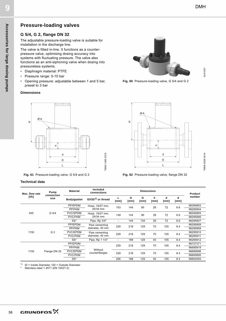
Ac
ce
ss
orie
s fo
r larg
e d
os
ing
pu
mp
s
58
DMH9
Pressure-loading valves
G 5/4, G 2, flange DN 32The adjustable pressure-loading valve is suitable for installation in the discharge line.
The valve is fitted in-line. It functions as a counter-pressure valve, optimising dosing accuracy into systems with fluctuating pressure. The valve also functions as an anti-siphoning valve when dosing into pressureless systems.
• Diaphragm material: PTFE
• Pressure range: 0-10 bar
• Opening pressure: adjustable between 1 and 5 bar, preset to 3 bar
Fig. 60 Pressure-loading valve, G 5/4 and G 2
Dimensions
Fig. 61 Pressure-loading valve, G 5/4 and G 2 Fig. 62 Pressure-loading valve, flange DN 32
Technical data
1) ID = Inside Diameter, OD = Outside Diameter* Stainless steel 1.4571 (EN 10027-2)
GrA
10
37
TM
04
14
60
03
10
Ø A
H
h
d
D
L
TM
06
05
29
04
14
Ø A
H
hd
D
L
Max. flow rate[l/h]
Pump connection
size
MaterialIncluded
connectionsDimensions
Product number
Body/gasket ID/OD1) or threadL
[mm]H
[mm]D
[mm]h
[mm]d
[mm]A
[mm]
400 G 5/4
PP/EPDM Hose, 19/27 mm, 25/34 mm
153 144 90 28 72 6.696295903
PP/FKM 96295904
PVC/EPDM Hose, 19/27 mm, 25/34 mm
149 144 90 28 72 6.696295905
PVC/FKM 96295906
SS* Pipe, Rp 3/4" - 144 134 28 72 6.6 96295907
1150 G 2
PP/EPDM Pipe cementing diameter, 40 mm
229 218 129 70 105 8.496295908
PP/FKM 96295909
PVC/EPDM Pipe cementing diameter, 40 mm
229 218 129 70 105 8.496295910
PVC/FKM 96295911
SS* Pipe, Rp 1 1/4" - 188 129 40 105 8.4 96295912
1150 Flange DN 32
PP/EPDM
Without counterflanges
229 218 129 70 105 8.496727371
PP/FKM 96695919
PVC/EPDM229 218 129 70 105 8.4
96695696
PVC/FKM 96695695
SS* 206 188 129 40 105 8.4 96652055
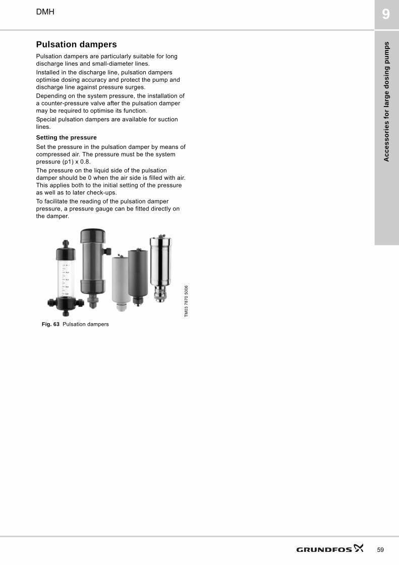
Ac
ce
ss
ori
es
fo
r la
rge
do
sin
g p
um
ps
DMH 9
Pulsation dampersPulsation dampers are particularly suitable for long discharge lines and small-diameter lines.
Installed in the discharge line, pulsation dampers optimise dosing accuracy and protect the pump and discharge line against pressure surges.
Depending on the system pressure, the installation of a counter-pressure valve after the pulsation damper may be required to optimise its function.
Special pulsation dampers are available for suction lines.
Setting the pressure
Set the pressure in the pulsation damper by means of compressed air. The pressure must be the system pressure (p1) x 0.8.
The pressure on the liquid side of the pulsation damper should be 0 when the air side is filled with air. This applies both to the initial setting of the pressure as well as to later check-ups.
To facilitate the reading of the pulsation damper pressure, a pressure gauge can be fitted directly on the damper.
Fig. 63 Pulsation dampers
TM
03
78
70
50
06
59
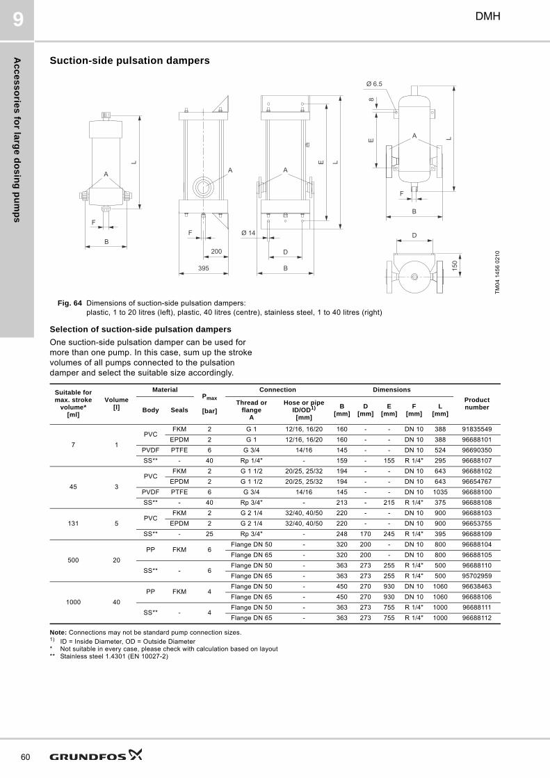
Ac
ce
ss
orie
s fo
r larg
e d
os
ing
pu
mp
s
60
DMH9
Suction-side pulsation dampers
Fig. 64 Dimensions of suction-side pulsation dampers: plastic, 1 to 20 litres (left), plastic, 40 litres (centre), stainless steel, 1 to 40 litres (right)
Selection of suction-side pulsation dampers
One suction-side pulsation damper can be used for more than one pump. In this case, sum up the stroke volumes of all pumps connected to the pulsation damper and select the suitable size accordingly.
Note: Connections may not be standard pump connection sizes.1) ID = Inside Diameter, OD = Outside Diameter* Not suitable in every case, please check with calculation based on layout** Stainless steel 1.4301 (EN 10027-2)
TM
04
14
56
02
10
L
F
B
A
E
D
Ø 14
200
395 B
L
F
AA
D
150
B
8E L
F
Ø 6.5
A
Suitable for max. stroke
volume*[ml]
Volume[l]
MaterialPmax
[bar]
Connection Dimensions
Product numberBody Seals
Thread or flange
A
Hose or pipeID/OD1)
[mm]
B[mm]
D[mm]
E[mm]
F[mm]
L[mm]
7 1
PVCFKM 2 G 1 12/16, 16/20 160 - - DN 10 388 91835549
EPDM 2 G 1 12/16, 16/20 160 - - DN 10 388 96688101
PVDF PTFE 6 G 3/4 14/16 145 - - DN 10 524 96690350
SS** - 40 Rp 1/4" - 159 - 155 R 1/4" 295 96688107
45 3
PVCFKM 2 G 1 1/2 20/25, 25/32 194 - - DN 10 643 96688102
EPDM 2 G 1 1/2 20/25, 25/32 194 - - DN 10 643 96654767
PVDF PTFE 6 G 3/4 14/16 145 - - DN 10 1035 96688100
SS** - 40 Rp 3/4" - 213 - 215 R 1/4" 375 96688108
131 5PVC
FKM 2 G 2 1/4 32/40, 40/50 220 - - DN 10 900 96688103
EPDM 2 G 2 1/4 32/40, 40/50 220 - - DN 10 900 96653755
SS** - 25 Rp 3/4" - 248 170 245 R 1/4" 395 96688109
500 20
PP FKM 6Flange DN 50 - 320 200 - DN 10 800 96688104
Flange DN 65 - 320 200 - DN 10 800 96688105
SS** - 6Flange DN 50 - 363 273 255 R 1/4" 500 96688110
Flange DN 65 - 363 273 255 R 1/4" 500 95702959
1000 40
PP FKM 4Flange DN 50 - 450 270 930 DN 10 1060 96638463
Flange DN 65 - 450 270 930 DN 10 1060 96688106
SS** - 4Flange DN 50 - 363 273 755 R 1/4" 1000 96688111
Flange DN 65 - 363 273 755 R 1/4" 1000 96688112
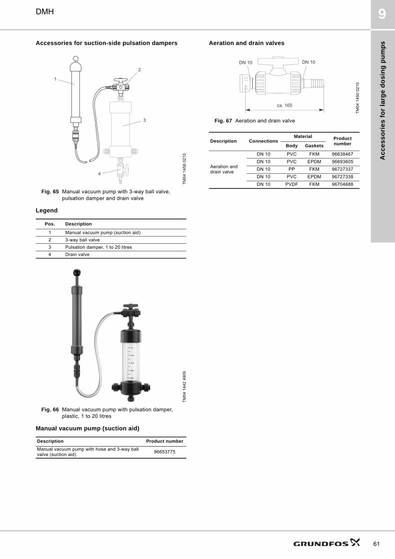
Ac
ce
ss
ori
es
fo
r la
rge
do
sin
g p
um
ps
DMH 9
Accessories for suction-side pulsation dampers
Fig. 65 Manual vacuum pump with 3-way ball valve, pulsation damper and drain valve
Legend
Fig. 66 Manual vacuum pump with pulsation damper, plastic, 1 to 20 litres
Manual vacuum pump (suction aid)
Aeration and drain valves
Fig. 67 Aeration and drain valve
TM
04
14
58
02
10
Pos. Description
1 Manual vacuum pump (suction aid)
2 3-way ball valve
3 Pulsation damper, 1 to 20 litres
4 Drain valve
TM
04
14
42
49
09
Description Product number
Manual vacuum pump with hose and 3-way ball valve (suction aid)
96653775
1
2
3
4
TM
04
14
50
02
10
Description ConnectionsMaterial Product
numberBody Gaskets
Aeration and drain valve
DN 10 PVC FKM 96638467
DN 10 PVC EPDM 96693605
DN 10 PP FKM 96727337
DN 10 PVC EPDM 96727338
DN 10 PVDF FKM 96704688
ca. 165
DN 10DN 10
61
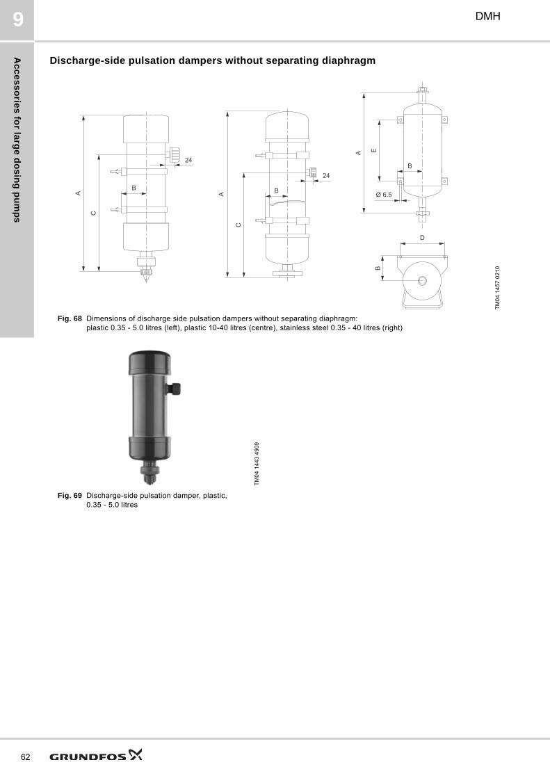
Ac
ce
ss
orie
s fo
r larg
e d
os
ing
pu
mp
s
62
DMH9
Discharge-side pulsation dampers without separating diaphragm
Fig. 68 Dimensions of discharge side pulsation dampers without separating diaphragm: plastic 0.35 - 5.0 litres (left), plastic 10-40 litres (centre), stainless steel 0.35 - 40 litres (right)
Fig. 69 Discharge-side pulsation damper, plastic, 0.35 - 5.0 litres
TM
04
14
57
02
10
A
C
24
B BA
C
24
A
Ø 6.5
E
D
B
B
TM
04
14
43
49
09
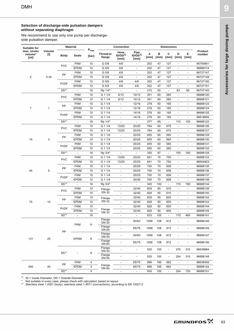
Ac
ce
ss
ori
es
fo
r la
rge
do
sin
g p
um
ps
DMH 9
Selection of discharge-side pulsation dampers without separating diaphragm
We recommend to use only one pump per discharge-side pulsation damper.
1) ID = Inside Diameter, OD = Outside Diameter* Not suitable in every case, please check with calculation based on layout** Stainless steel 1.4301 (body), stainless steel 1.4571 (connections), according to EN 10027-2
Suitable for max. stroke
volume*[ml]
Volume[l]
MaterialPmax
[bar]
Connection Dimensions
Product numberBody Seals
Thread or flange
HoseID/OD1)
[mm]
PipeID/OD1)
[mm]
A[mm]
B[mm]
C[mm]
D[mm]
E[mm]
2 0.35
PVCFKM 10 G 5/8 4/6 - 202 47 127 - - 95700901
EPDM 10 G 5/8 4/6 - 202 47 127 - - 96688114
PPFKM 10 G 5/8 4/6 - 202 47 127 - - 96727147
EPDM 10 G 5/8 4/6 - 202 47 127 - - 96727148
PVDFFKM 10 G 5/8 4/6 4/6 202 47 127 - - 96727150
EPDM 10 G 5/8 4/6 4/6 202 47 127 - - 96727151
SS** - 16 Rp 1/4" - - 215 50 - 83 85 96727145
7 1
PVCFKM 10 G 1 1/4 6/12 10/12 351 60 260 - - 96688120
EPDM 10 G 1 1/4 6/12 10/12 351 60 260 - - 96688121
PPFKM 10 G 1 1/4 - 12/16 278 60 165 - - 96688123
EPDM 10 G 1 1/4 - 12/16 278 60 165 - - 96688124
PVDFFKM 10 G 1 1/4 - 14/16 278 60 165 - - 96688125
EPDM 10 G 1 1/4 - 14/16 278 60 165 - - 96619905
SS** - 16 Rp 1/4" - - 277 65 - 110 125 96688122
19 3
PVCFKM 10 G 1 1/4 13/20 20/25 764 60 675 - - 96688126
EPDM 10 G 1 1/4 13/20 20/25 764 60 675 - - 96688127
PPFKM 10 G 1 1/4 - 20/25 655 60 565 - - 96688129
EPDM 10 G 1 1/4 - 20/25 655 60 565 - - 96688130
PVDFFKM 10 G 1 1/4 - 20/25 655 60 565 - - 96688131
EPDM 10 G 1 1/4 - 20/25 655 60 565 - - 96688132
SS** - 16 Rp 3/4" - - 355 87 - 150 160 96688128
45 5
PVCFKM 10 G 1 1/4 13/20 20/25 841 70 750 - - 96688133
EPDM 10 G 1 1/4 13/20 20/25 841 70 750 - - 96654923
PPFKM 10 G 1 1/4 - 20/25 700 70 608 - - 96688135
EPDM 10 G 1 1/4 - 20/25 700 70 608 - - 96688136
PVDFFKM 10 G 1 1/4 - 20/25 700 70 608 - - 96688137
EPDM 10 G 1 1/4 - 20/25 700 70 608 - - 96688138
SS** - 16 Rp 3/4" - - 345 100 - 170 190 96688134
75 10
PVCFKM 10 Flange
DN 32- 32/40 829 95 610 - - 96688139
EPDM 10 - 32/40 829 95 610 - - 96688140
PPFKM 10 Flange
DN 32- 32/40 829 95 605 - - 96688142
EPDM 10 - 32/40 829 95 605 - - 96688143
PVDFFKM 10
Flange DN 32
- 32/40 829 95 605 - - 96688144
EPDM 10 - 32/40 829 95 605 - - 96688145
SS** - 16 - - 633 100 - 170 460 96688141
131 20
PP
FKM 6
Flange DN 50
- 50/63 1056 108 812 - - 96688146
Flange DN 65
- 65/75 1056 108 812 - - 96688149
EPDM 6
Flange DN 50
- 50/63 1056 108 812 - - 96688147
Flange DN 65
- 65/75 1056 108 812 - - 96688150
SS** - 6
Flange DN 50
- - 525 150 - 270 310 96639884
Flange DN 65
- - 525 150 - 254 310 96688148
500 40PP
FKM 4Flange DN 65
- 65/75 896 166 662 - - 96638405
EPDM 4 - 65/75 896 166 662 - - 96688152
SS** - 4 - - 935 150 - 254 720 96688151
63
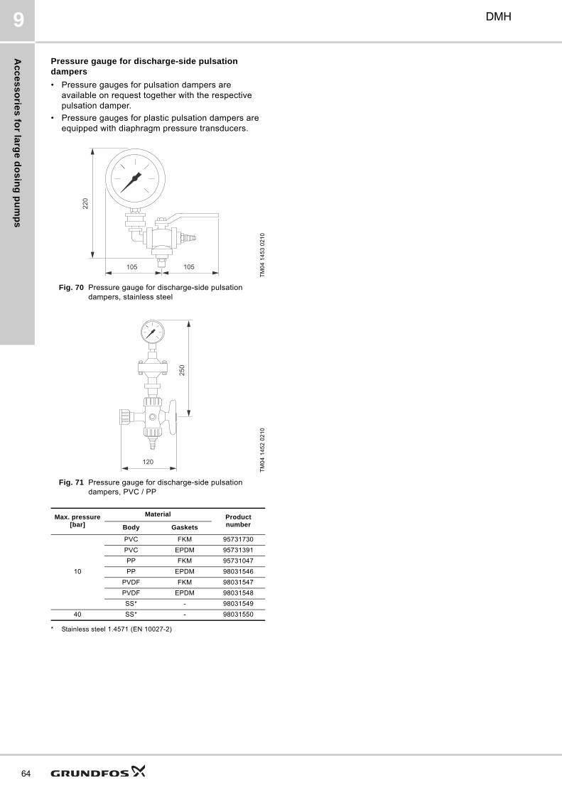
Ac
ce
ss
orie
s fo
r larg
e d
os
ing
pu
mp
s
64
DMH9
Pressure gauge for discharge-side pulsation dampers
• Pressure gauges for pulsation dampers are available on request together with the respective pulsation damper.
• Pressure gauges for plastic pulsation dampers are equipped with diaphragm pressure transducers.
Fig. 70 Pressure gauge for discharge-side pulsation dampers, stainless steel
Fig. 71 Pressure gauge for discharge-side pulsation dampers, PVC / PP
* Stainless steel 1.4571 (EN 10027-2)
TM
04
14
53
02
10
TM
04
14
52
02
10
Max. pressure [bar]
Material Product numberBody Gaskets
10
PVC FKM 95731730
PVC EPDM 95731391
PP FKM 95731047
PP EPDM 98031546
PVDF FKM 98031547
PVDF EPDM 98031548
SS* - 98031549
40 SS* - 98031550
105 105
220
120
250
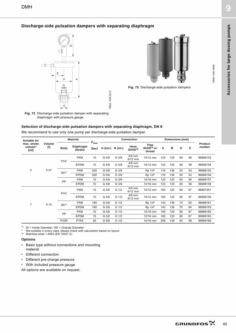
Ac
ce
ss
ori
es
fo
r la
rge
do
sin
g p
um
ps
DMH 9
Discharge-side pulsation dampers with separating diaphragm
Fig. 72 Discharge-side pulsation damper with separating diaphragm with pressure gauge
Fig. 73 Discharge-side pulsation dampers
Selection of discharge-side pulsation dampers with separating diaphragm, DN 8
We recommend to use only one pump per discharge-side pulsation damper.
1) ID = Inside Diameter, OD = Outside Diameter* Not suitable in every case, please check with calculation based on layout** Stainless steel 1.4404 (EN 10027-2)
Options
• Basic type without connections and mounting material
• Different connection
• Different pre-charge pressure
• With included pressure gauge.
All options are available on request.
TM
04
14
59
02
10
0
0
0
0
E
D
G
A
R
B
TM
04
14
44
49
09
Suitable for max. stroke
volume*[ml]
Volume[l]
MaterialPmax
[bar]
Connection Dimensions [mm]
Product numberBody
Diaphragm (Seals)
G (ext.) R (int.)Hose
ID/OD1)
PipeID/OD1) or
threadA B D E
2 0.07
PVCFKM 10 G 5/8 G 3/8
4/6 mm6/12 mm
10/12 mm 123 120 60 58 96688153
EPDM 10 G 5/8 G 3/84/6 mm
6/12 mm10/12 mm 123 120 60 58 96688154
SS**FKM 200 G 5/8 G 3/8 Rp 1/4" 118 136 55 53 96688155
EPDM 200 G 5/8 G 3/8 Rp 1/4" 118 136 55 53 96688156
PPFKM 10 G 5/8 G 3/8 12/16 mm 123 120 60 58 96688157
EPDM 10 G 5/8 G 3/8 12/16 mm 123 120 60 58 96688158
7 0.15
PVCFKM 10 G 5/8 G 1/2
4/6 mm6/12 mm
10/12 mm 160 120 80 67 96697351
EPDM 10 G 5/8 G 1/24/6 mm
6/12 mm10/12 mm 160 120 80 67 96688159
SS**FKM 180 G 5/8 G 1/2 Rp 1/4" 143 136 70 64 96688161
EPDM 180 G 5/8 G 1/2 Rp 1/4" 143 136 70 64 96688163
PPFKM 10 G 5/8 G 1/2 12/16 mm 160 120 80 67 96688164
EPDM 10 G 5/8 G 1/2 12/16 mm 160 120 80 67 96688165
PVDF PTFE 20 G 5/8 G 1/2 14/16 mm 206 136 64 58 96688166
65
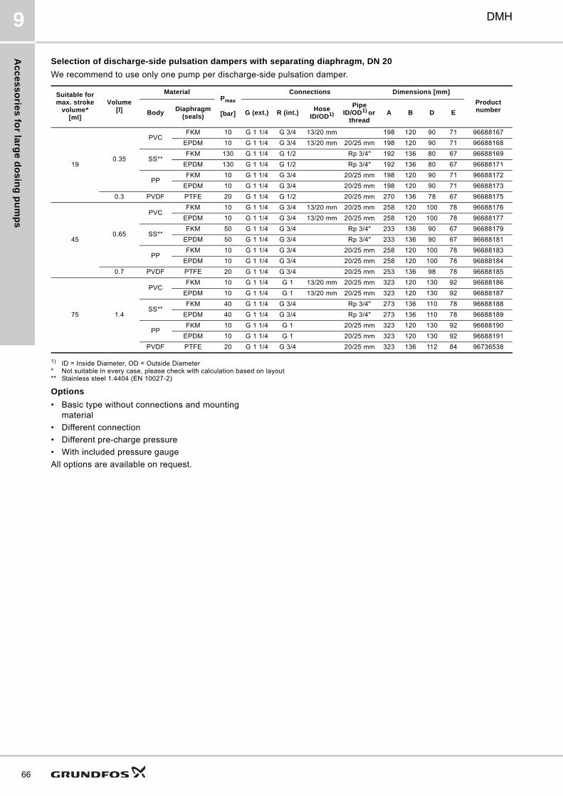
Ac
ce
ss
orie
s fo
r larg
e d
os
ing
pu
mp
s
66
DMH9
Selection of discharge-side pulsation dampers with separating diaphragm, DN 20
We recommend to use only one pump per discharge-side pulsation damper.
1) ID = Inside Diameter, OD = Outside Diameter* Not suitable in every case, please check with calculation based on layout** Stainless steel 1.4404 (EN 10027-2)
Options
• Basic type without connections and mounting material
• Different connection
• Different pre-charge pressure
• With included pressure gauge
All options are available on request.
Suitable for max. stroke
volume*[ml]
Volume[l]
MaterialPmax
[bar]
Connections Dimensions [mm]
Product numberBody
Diaphragm (seals)
G (ext.) R (int.)Hose
ID/OD1)
Pipe ID/OD1) or
threadA B D E
190.35
PVCFKM 10 G 1 1/4 G 3/4 13/20 mm 198 120 90 71 96688167
EPDM 10 G 1 1/4 G 3/4 13/20 mm 20/25 mm 198 120 90 71 96688168
SS**FKM 130 G 1 1/4 G 1/2 Rp 3/4" 192 136 80 67 96688169
EPDM 130 G 1 1/4 G 1/2 Rp 3/4" 192 136 80 67 96688171
PPFKM 10 G 1 1/4 G 3/4 20/25 mm 198 120 90 71 96688172
EPDM 10 G 1 1/4 G 3/4 20/25 mm 198 120 90 71 96688173
0.3 PVDF PTFE 20 G 1 1/4 G 1/2 20/25 mm 270 136 78 67 96688175
450.65
PVCFKM 10 G 1 1/4 G 3/4 13/20 mm 20/25 mm 258 120 100 78 96688176
EPDM 10 G 1 1/4 G 3/4 13/20 mm 20/25 mm 258 120 100 78 96688177
SS**FKM 50 G 1 1/4 G 3/4 Rp 3/4" 233 136 90 67 96688179
EPDM 50 G 1 1/4 G 3/4 Rp 3/4" 233 136 90 67 96688181
PPFKM 10 G 1 1/4 G 3/4 20/25 mm 258 120 100 78 96688183
EPDM 10 G 1 1/4 G 3/4 20/25 mm 258 120 100 78 96688184
0.7 PVDF PTFE 20 G 1 1/4 G 3/4 20/25 mm 253 136 98 78 96688185
75 1.4
PVCFKM 10 G 1 1/4 G 1 13/20 mm 20/25 mm 323 120 130 92 96688186
EPDM 10 G 1 1/4 G 1 13/20 mm 20/25 mm 323 120 130 92 96688187
SS**FKM 40 G 1 1/4 G 3/4 Rp 3/4" 273 136 110 78 96688188
EPDM 40 G 1 1/4 G 3/4 Rp 3/4" 273 136 110 78 96688189
PPFKM 10 G 1 1/4 G 1 20/25 mm 323 120 130 92 96688190
EPDM 10 G 1 1/4 G 1 20/25 mm 323 120 130 92 96688191
PVDF PTFE 20 G 1 1/4 G 3/4 20/25 mm 323 136 112 84 96736538
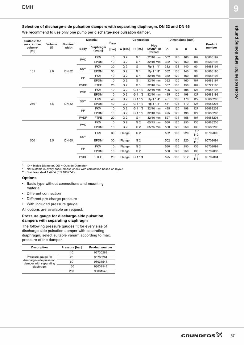
Ac
ce
ss
ori
es
fo
r la
rge
do
sin
g p
um
ps
DMH 9
Selection of discharge-side pulsation dampers with separating diaphragm, DN 32 and DN 65
We recommend to use only one pump per discharge-side pulsation damper.
1) ID = Inside Diameter, OD = Outside Diameter* Not suitable in every case, please check with calculation based on layout** Stainless steel 1.4404 (EN 10027-2)
Options
• Basic type without connections and mounting material
• Different connection
• Different pre-charge pressure
• With included pressure gauge
All options are available on request.
Pressure gauge for discharge-side pulsation dampers with separating diaphragm
The following pressure gauges fit for every size of discharge side pulsation damper with separating diaphragm, select suitable variant according to max. pressure of the damper.
Suitable for max. stroke
volume*[ml]
Volume[l]
Nominal width
MaterialPmax
[bar]
Connection Dimensions [mm]
Product numberBody
Diaphragm (seals)
G (ext.) R (int.)Pipe
ID/OD1) or thread
A B D E
131 2.6 DN 32
PVCFKM 10 G 2 G 1 32/40 mm 362 120 160 107 96688192
EPDM 10 G 2 G 1 32/40 mm 362 120 160 107 96688193
SS**FKM 30 G 2 G 1 Rp 1 1/4" 332 136 140 90 96688194
EPDM 30 G 2 G 1 Rp 1 1/4" 332 136 140 90 96688195
PPFKM 10 G 2 G 1 32/40 mm 362 120 160 107 96688196
EPDM 10 G 2 G 1 32/40 mm 362 120 160 107 96688197
PVDF PTFE 20 G 2 G 1 32/40 mm 357 136 158 107 96727195
256 5.6 DN 32
PVCFKM 10 G 2 G 1 1/2 32/40 mm 495 120 198 127 96688198
EPDM 10 G 2 G 1 1/2 32/40 mm 495 120 198 127 96688199
SS**FKM 40 G 2 G 1 1/2 Rp 1 1/4" 451 136 170 127 96688200
EPDM 40 G 2 G 1 1/2 Rp 1 1/4" 451 136 170 127 96688201
PPFKM 10 G 2 G 1 1/2 32/40 mm 495 120 198 127 96688202
EPDM 10 G 2 G 1 1/2 32/40 mm 495 120 198 127 96688203
PVDF PTFE 20 G 2 G 1 32/40 mm 527 136 158 107 96688204
500 9.5 DN 65
PVCFKM 10 G 2 G 2 65/75 mm 560 120 250 133 96688205
EPDM 10 G 2 G 2 65/75 mm 560 120 250 133 96688206
SS**FKM 30 Flange G 2 502 136 220
111/119
95702090
EPDM 30 Flange G 2 502 136 220111/119
95702091
PPFKM 10 Flange G 2 560 120 250 133 95702092
EPDM 10 Flange G 2 560 120 250 133 95702093
PVDF PTFE 20 Flange G 1 1/4 525 136 212111/113
95702094
Description Pressure [bar] Product number
Pressure gauge for discharge-side pulsation damper with separating
diaphragm
10 95730263
25 95730264
60 98031543
160 98031544
250 98031545
67
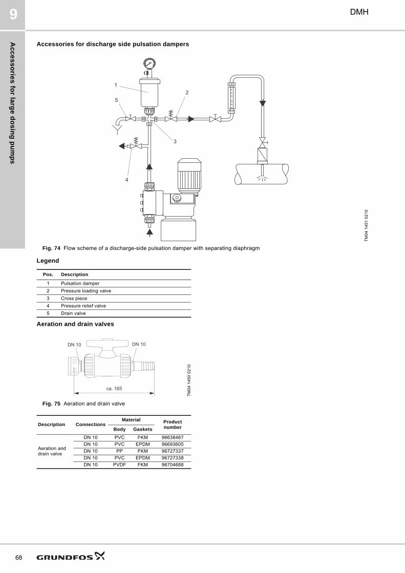
Ac
ce
ss
orie
s fo
r larg
e d
os
ing
pu
mp
s
68
DMH9
Accessories for discharge side pulsation dampers
Fig. 74 Flow scheme of a discharge-side pulsation damper with separating diaphragm
Legend
Aeration and drain valves
Fig. 75 Aeration and drain valve
TM
04
14
51
02
10
12
3
4
5
Pos. Description
1 Pulsation damper
2 Pressure loading valve
3 Cross piece
4 Pressure relief valve
5 Drain valve
TM
04
14
50
02
10
Description ConnectionsMaterial Product
numberBody Gaskets
Aeration and drain valve
DN 10 PVC FKM 96638467
DN 10 PVC EPDM 96693605
DN 10 PP FKM 96727337
DN 10 PVC EPDM 96727338
DN 10 PVDF FKM 96704688
ca. 165
DN 10DN 10
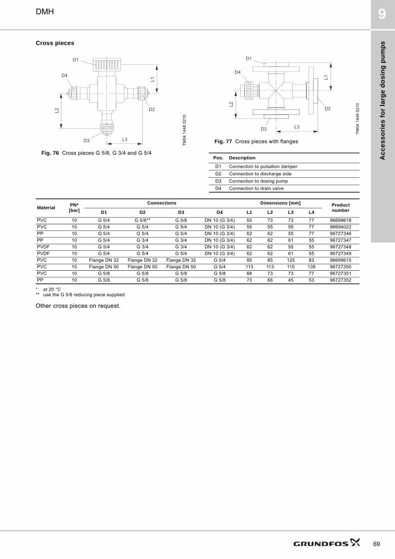
Ac
ce
ss
ori
es
fo
r la
rge
do
sin
g p
um
ps
DMH 9
Cross pieces
Fig. 76 Cross pieces G 5/8, G 3/4 and G 5/4
Fig. 77 Cross pieces with flanges
* at 20 °C** use the G 5/8 reducing piece supplied
Other cross pieces on request.
TM
04
14
48
02
10
L1
L2
L3
D1
D2
D3
D4
TM
04
14
49
02
10
Pos. Description
D1 Connection to pulsation damper
D2 Connection to discharge side
D3 Connection to dosing pump
D4 Connection to drain valve
L3
L2
L1
D1
D2
D3
D4
MaterialPN*[bar]
Connections Dimensions [mm] Product numberD1 D2 D3 D4 L1 L2 L3 L4
PVC 10 G 5/4 G 5/8** G 5/8 DN 10 (G 3/4) 55 73 73 77 96699618
PVC 10 G 5/4 G 5/4 G 5/4 DN 10 (G 3/4) 55 55 55 77 96694022
PP 10 G 5/4 G 5/4 G 5/4 DN 10 (G 3/4) 62 62 55 77 96727346
PP 10 G 5/4 G 3/4 G 3/4 DN 10 (G 3/4) 62 62 61 55 96727347
PVDF 10 G 5/4 G 3/4 G 3/4 DN 10 (G 3/4) 62 62 55 55 96727348
PVDF 10 G 5/4 G 5/4 G 5/4 DN 10 (G 3/4) 62 62 61 55 96727349
PVC 10 Flange DN 32 Flange DN 32 Flange DN 32 G 5/4 85 85 125 83 96699615
PVC 10 Flange DN 50 Flange DN 50 Flange DN 50 G 5/4 113 113 115 139 96727350
PVC 10 G 5/8 G 5/8 G 5/8 G 5/8 66 73 73 77 96727351
PP 10 G 5/8 G 5/8 G 5/8 G 5/8 73 66 45 53 96727352
69
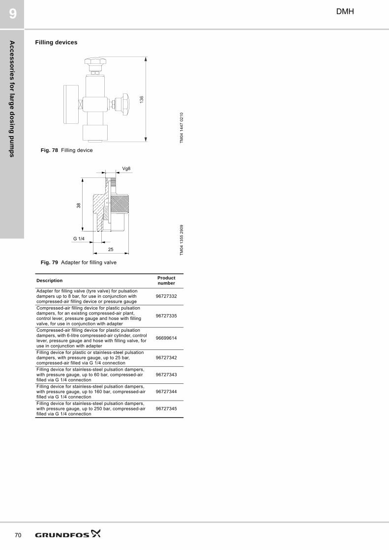
Ac
ce
ss
orie
s fo
r larg
e d
os
ing
pu
mp
s
70
DMH9
Filling devices
Fig. 78 Filling device
Fig. 79 Adapter for filling valve
TM
04
14
47
02
10
TM
04
13
55
29
09
DescriptionProduct number
Adapter for filling valve (tyre valve) for pulsation dampers up to 8 bar, for use in conjunction with compressed-air filling device or pressure gauge
96727332
Compressed-air filling device for plastic pulsation dampers, for an existing compressed-air plant, control lever, pressure gauge and hose with filling valve, for use in conjunction with adapter
96727335
Compressed-air filling device for plastic pulsation dampers, with 6-litre compressed-air cylinder, control lever, pressure gauge and hose with filling valve, for use in conjunction with adapter
96699614
Filling device for plastic or stainless-steel pulsation dampers, with pressure gauge, up to 25 bar, compressed-air filled via G 1/4 connection
96727342
Filling device for stainless-steel pulsation dampers, with pressure gauge, up to 60 bar, compressed-air filled via G 1/4 connection
96727343
Filling device for stainless-steel pulsation dampers, with pressure gauge, up to 160 bar, compressed-air filled via G 1/4 connection
96727344
Filling device for stainless-steel pulsation dampers, with pressure gauge, up to 250 bar, compressed-air filled via G 1/4 connection
96727345
136
25
G 1/4
38
Vg8
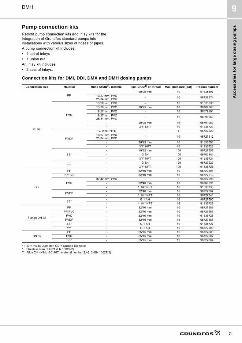
Ac
ce
ss
ori
es
fo
r la
rge
do
sin
g p
um
ps
DMH 9
Pump connection kitsRetrofit pump connection kits and inlay kits for the integration of Grundfos standard pumps into installations with various sizes of hoses or pipes.
A pump connection kit includes:
• 1 set of inlays
• 1 union nut.
An inlay kit includes:
• 2 sets of inlays.
Connection kits for DMI, DDI, DMX and DMH dosing pumps
1) ID = Inside Diameter, OD = Outside Diameter* Stainless steel 1.4571 (EN 10027-2)** Alloy C-4 (NiMo16Cr16Ti) material number 2.4610 (EN 10027-2)
Connection size Material Hose ID/OD1), material Pipe ID/OD1) or thread Max. pressure [bar] Product number
G 5/4
PP- 20/25 mm 10 91835697
19/27 mm, PVC25/34 mm, PVC
- 10 96727574
PVC
13/20 mm, PVC - 10 91835696
13/20 mm, PVC 20/25 mm 10 96704663
19/27 mm, PVC - 10 96679391
19/27 mm, PVC25/34 mm, PVC
- 10 96699969
- 20/25 mm 16 96701989
- 3/4" NPT 10 91835723
PVDF
12/ mm, PTFE - 4 96727620
19/27 mm, PVC25/34 mm, PVC
- 10 96727612
- 20/25 mm 10 91835698
- 3/4" NPT 10 91835726
SS*
- 19/22 mm 100 96727555
- G 3/4 100 96700184
- 3/4" NPT 100 91835724
Y**- G 3/4 100 96727523
- 3/4" NPT 100 91835725
G 2
PP - 32/40 mm 10 96727596
PP/PVC - 32/40 mm 16 96727610
PVC
32/42 mm, PVC - 0 96727598
- 32/40 mm 10 96700091
- 1 1/4" NPT 10 91835730
PVDF- 32/40 mm 16 96727597
- 1 1/4" NPT 10 96727541
SS*- G 1 1/4 16 96727595
- 1 1/4" NPT 16 91835729
Flange DN 32
PP - 32/40 mm 10 96727589
PP/PVC - 32/40 mm 10 96727586
PVC - 32/40 mm 10 91835728
PVDF - 32/40 mm 16 96727588
SS* - G 1 1/4 10 91835727
Y** - G 1 1/4 10 96727609
DN 65
PP - 65/75 mm 10 96727603
PVC - 65/75 mm 10 96727602
SS* - 65/75 mm 10 96727604
71
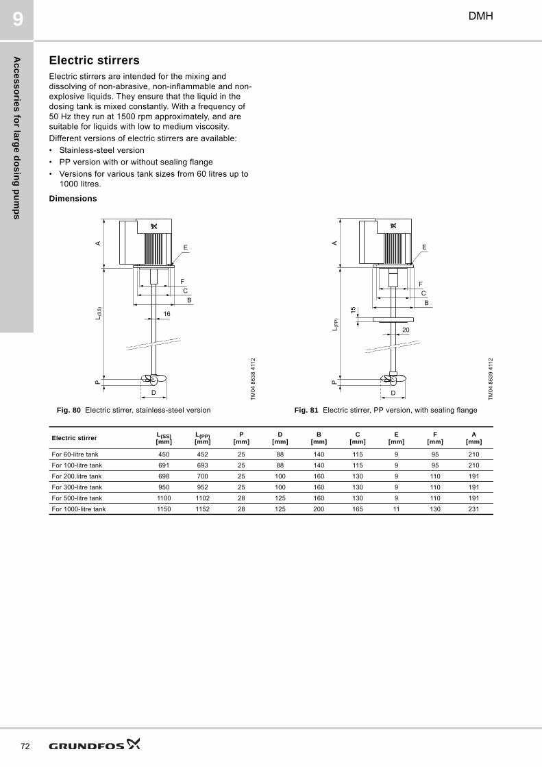
Ac
ce
ss
orie
s fo
r larg
e d
os
ing
pu
mp
s
72
DMH9
Electric stirrersElectric stirrers are intended for the mixing and dissolving of non-abrasive, non-inflammable and non-explosive liquids. They ensure that the liquid in the dosing tank is mixed constantly. With a frequency of 50 Hz they run at 1500 rpm approximately, and are suitable for liquids with low to medium viscosity.
Different versions of electric stirrers are available:
• Stainless-steel version
• PP version with or without sealing flange
• Versions for various tank sizes from 60 litres up to 1000 litres.
Dimensions
Fig. 80 Electric stirrer, stainless-steel version Fig. 81 Electric stirrer, PP version, with sealing flange
TM
04
86
38
411
2
16
D
AL (
SS
)P
BC
F
E
TM
04
86
39
411
2
20
D
PL (
PP
)A
15
FCB
E
Electric stirrerL(SS)[mm]
L(PP)[mm]
P[mm]
D[mm]
B[mm]
C[mm]
E[mm]
F[mm]
A[mm]
For 60-litre tank 450 452 25 88 140 115 9 95 210
For 100-litre tank 691 693 25 88 140 115 9 95 210
For 200.litre tank 698 700 25 100 160 130 9 110 191
For 300-litre tank 950 952 25 100 160 130 9 110 191
For 500-litre tank 1100 1102 28 125 160 130 9 110 191
For 1000-litre tank 1150 1152 28 125 200 165 11 130 231
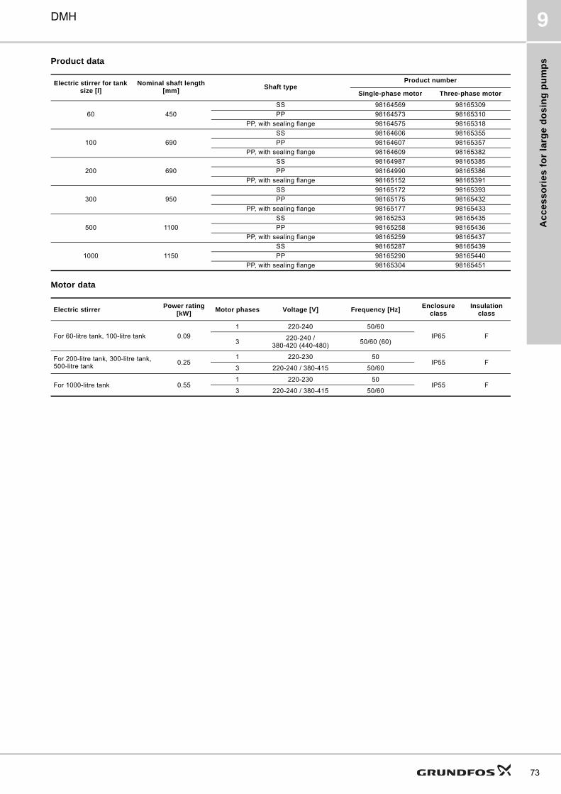
Ac
ce
ss
ori
es
fo
r la
rge
do
sin
g p
um
ps
DMH 9
Product data
Motor data
Electric stirrer for tank size [l]
Nominal shaft length [mm]
Shaft typeProduct number
Single-phase motor Three-phase motor
60 450
SS 98164569 98165309
PP 98164573 98165310
PP, with sealing flange 98164575 98165318
100 690
SS 98164606 98165355
PP 98164607 98165357
PP, with sealing flange 98164609 98165382
200 690
SS 98164987 98165385
PP 98164990 98165386
PP, with sealing flange 98165152 98165391
300 950
SS 98165172 98165393
PP 98165175 98165432
PP, with sealing flange 98165177 98165433
500 1100
SS 98165253 98165435
PP 98165258 98165436
PP, with sealing flange 98165259 98165437
1000 1150
SS 98165287 98165439
PP 98165290 98165440
PP, with sealing flange 98165304 98165451
Electric stirrerPower rating
[kW]Motor phases Voltage [V] Frequency [Hz]
Enclosure class
Insulation class
For 60-litre tank, 100-litre tank 0.09
1 220-240 50/60
IP65 F3
220-240 / 380-420 (440-480)
50/60 (60)
For 200-litre tank, 300-litre tank, 500-litre tank
0.251 220-230 50
IP55 F3 220-240 / 380-415 50/60
For 1000-litre tank 0.551 220-230 50
IP55 F3 220-240 / 380-415 50/60
73
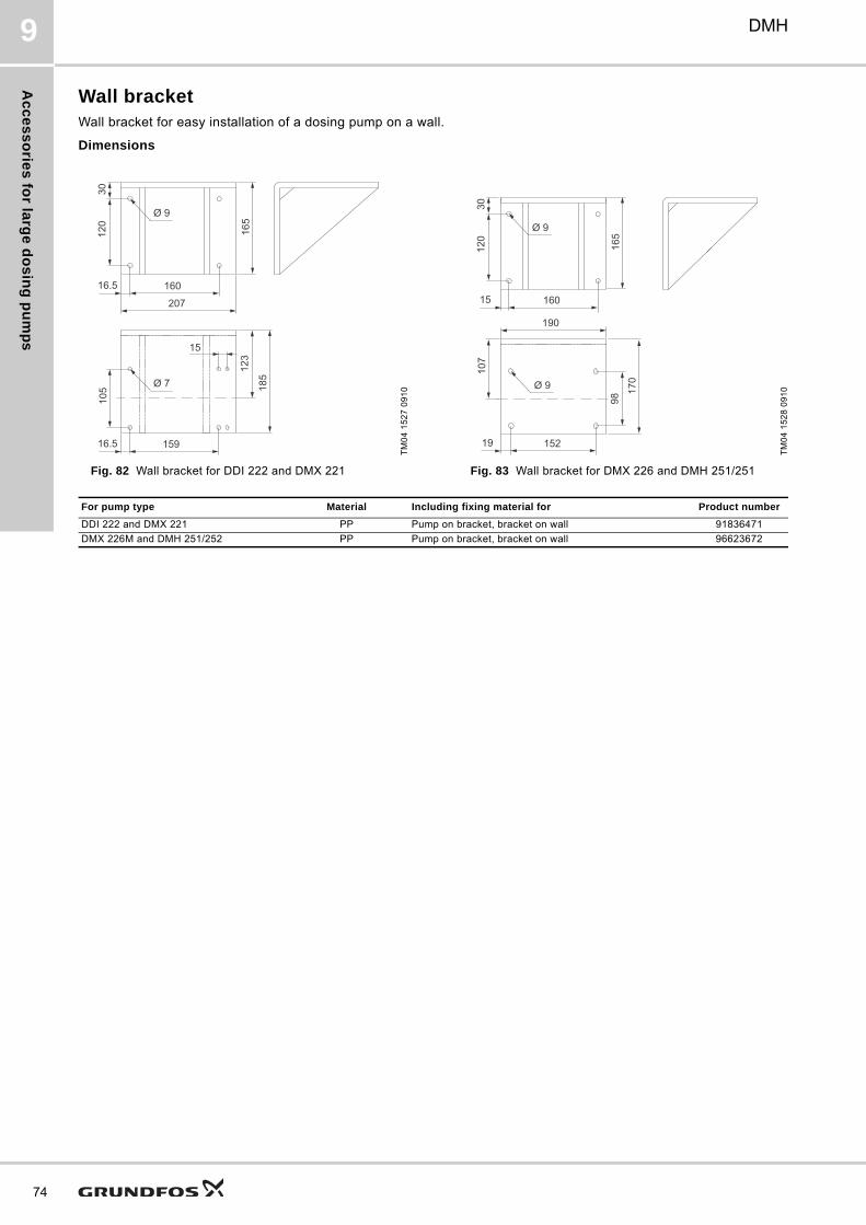
Ac
ce
ss
orie
s fo
r larg
e d
os
ing
pu
mp
s
74
DMH9
Wall bracketWall bracket for easy installation of a dosing pump on a wall.
Dimensions
Fig. 82 Wall bracket for DDI 222 and DMX 221 Fig. 83 Wall bracket for DMX 226 and DMH 251/251
TM
04
15
27
09
10
120
30
160
105
16.5
207
15916.5
15
165
123
185Ø 7
Ø 9
TM
04
15
28
09
10
120
30
160
107
15
190
15219
165
98
170
Ø 9
Ø 9
For pump type Material Including fixing material for Product number
DDI 222 and DMX 221 PP Pump on bracket, bracket on wall 91836471
DMX 226M and DMH 251/252 PP Pump on bracket, bracket on wall 96623672
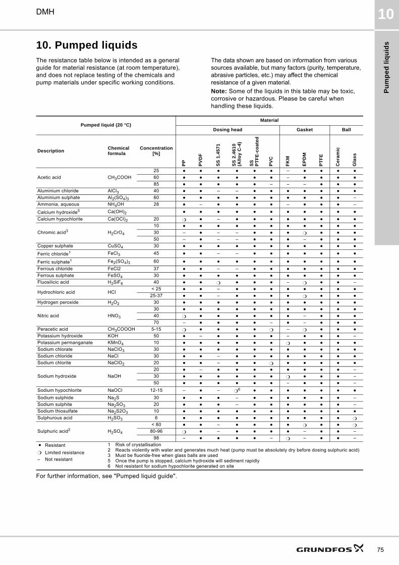
Pu
mp
ed
liq
uid
s
75
DMH 10
10. Pumped liquidsThe resistance table below is intended as a general guide for material resistance (at room temperature), and does not replace testing of the chemicals and pump materials under specific working conditions.
The data shown are based on information from various sources available, but many factors (purity, temperature, abrasive particles, etc.) may affect the chemical resistance of a given material.
Note: Some of the liquids in this table may be toxic, corrosive or hazardous. Please be careful when handling these liquids.
For further information, see "Pumped liquid guide".
Pumped liquid (20 °C)Material
Dosing head Gasket Ball
DescriptionChemical formula
Concentration[%]
PP
PV
DF
SS
1.4
57
1
SS
2.4
61
0
(All
oy
C-4
)
SS
P
TF
E-c
oa
ted
PV
C
FK
M
EP
DM
PT
FE
Ce
ram
ic
Gla
ss
Acetic acid CH3COOH
25 –
60 –
85 – – –
Aluminium chloride AlCl3 40 – –
Aluminium sulphate Al2(SO4)3 60 –
Ammonia, aqueous NH4OH 28 – – –
Calcium hydroxide5 Ca(OH)2
Calcium hypochlorite Ca(OCl)2 20 –
Chromic acid3 H2CrO4
10
30 – – –
50 – – – –
Copper sulphate CuSO4 30
Ferric chloride1 FeCl3 45 – –
Ferric sulphate1 Fe2(SO4)3 60
Ferrous chloride FeCl2 37 – –
Ferrous sulphate FeSO4 30
Fluosilicic acid H2SiF6 40 – –
Hydrochloric acid HCl< 25 –
25-37 –
Hydrogen peroxide H2O2 30
Nitric acid HNO3
30
40 –
70 – – –
Peracetic acid CH3COOOH 5-15 –
Potassium hydroxide KOH 50 – – –
Potassium permanganate KMnO4 10
Sodium chlorate NaClO3 30
Sodium chloride NaCl 30 –
Sodium chlorite NaClO2 20 –
Sodium hydroxide NaOH
20 – –
30 –
50 – –
Sodium hypochlorite NaOCl 12-15 – – 6
Sodium sulphide Na2S 30 – –
Sodium sulphite Na2SO3 20 – –
Sodium thiosulfate Na2S2O3 10
Sulphurous acid H2SO3 6
Sulphuric acid2 H2SO4
< 80 – 80-96 – – –
98 – – – –
Resistant 1 Risk of crystallisation2 Reacts violently with water and generates much heat (pump must be absolutely dry before dosing sulphuric acid)3 Must be fluoride-free when glass balls are used5 Once the pump is stopped, calcium hydroxide will sediment rapidly6 Not resistant for sodium hypochlorite generated on site
Limited resistance
– Not resistant
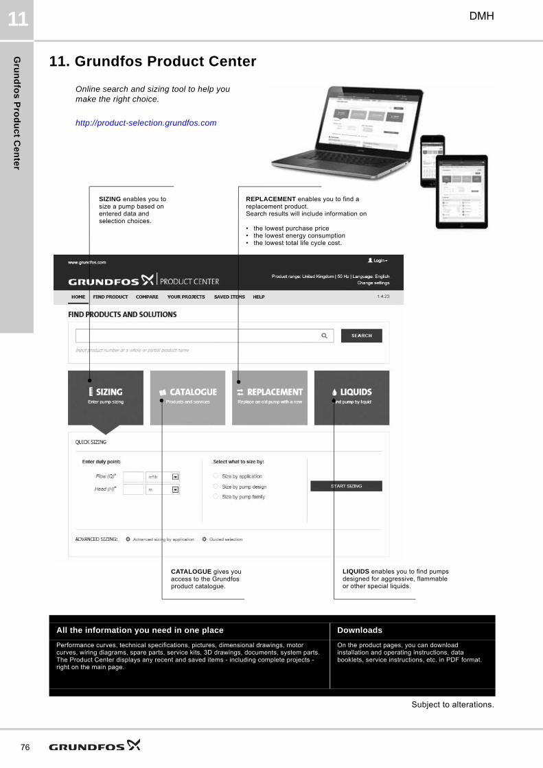
Gru
nd
fos
Pro
du
ct C
en
ter
76
DMH11
11. Grundfos Product Center
Subject to alterations.
All the information you need in one place Downloads
Performance curves, technical specifications, pictures, dimensional drawings, motor curves, wiring diagrams, spare parts, service kits, 3D drawings, documents, system parts. The Product Center displays any recent and saved items - including complete projects - right on the main page.
On the product pages, you can download installation and operating instructions, data booklets, service instructions, etc. in PDF format.
SIZING enables you to size a pump based on entered data and selection choices.
Online search and sizing tool to help you make the right choice.
http://product-selection.grundfos.com
REPLACEMENT enables you to find a replacement product.Search results will include information on
• the lowest purchase price• the lowest energy consumption• the lowest total life cycle cost.
CATALOGUE gives you access to the Grundfos product catalogue.
LIQUIDS enables you to find pumps designed for aggressive, flammable or other special liquids.

77
GRUNDFOS A/S DK-8850 Bjerringbro . DenmarkTelephone: +45 87 50 14 00www.grundfos.com
95724362 1016
ECM: 1187502 Th
e n
am
e G
run
dfo
s, t
he
Gru
nd
fos
log
o,
an
d b
e t
hin
k i
nn
ov
ate
are
re
gis
tere
d t
rad
em
ark
s o
wn
ed
by
Gru
nd
fos
Ho
ldin
g A
/S o
r G
run
dfo
s A
/S,
De
nm
ark
. A
ll ri
gh
ts r
ese
rve
d w
orl
dw
ide
.©
Co
pyr
igh
t G
run
dfo
s H
old
ing
A/S