Embed Size (px)
Citation preview
GRUNDFOS DATA BOOKLET
Grundfos valvesNon-return valves and foot valves
Ta
ble
of c
on
ten
ts
2
Grundfos valves
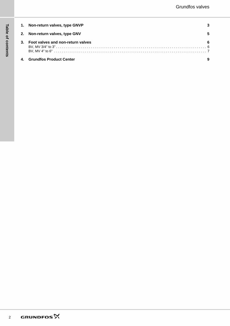
1. Non-return valves, type GNVP 3
2. Non-return valves, type GNV 5
3. Foot valves and non-return valves 6BV, MV 3/4" to 3" . . . . . . . . . . . . . . . . . . . . . . . . . . . . . . . . . . . . . . . . . . . . . . . . . . . . . . . . . . . . . . . . . . . . . . . . . . . . . . 6BV, MV 4" to 6" . . . . . . . . . . . . . . . . . . . . . . . . . . . . . . . . . . . . . . . . . . . . . . . . . . . . . . . . . . . . . . . . . . . . . . . . . . . . . . . 7
4. Grundfos Product Center 9
No
n-r
etu
rn v
alv
es
, ty
pe
GN
VP
Grundfos valves 1
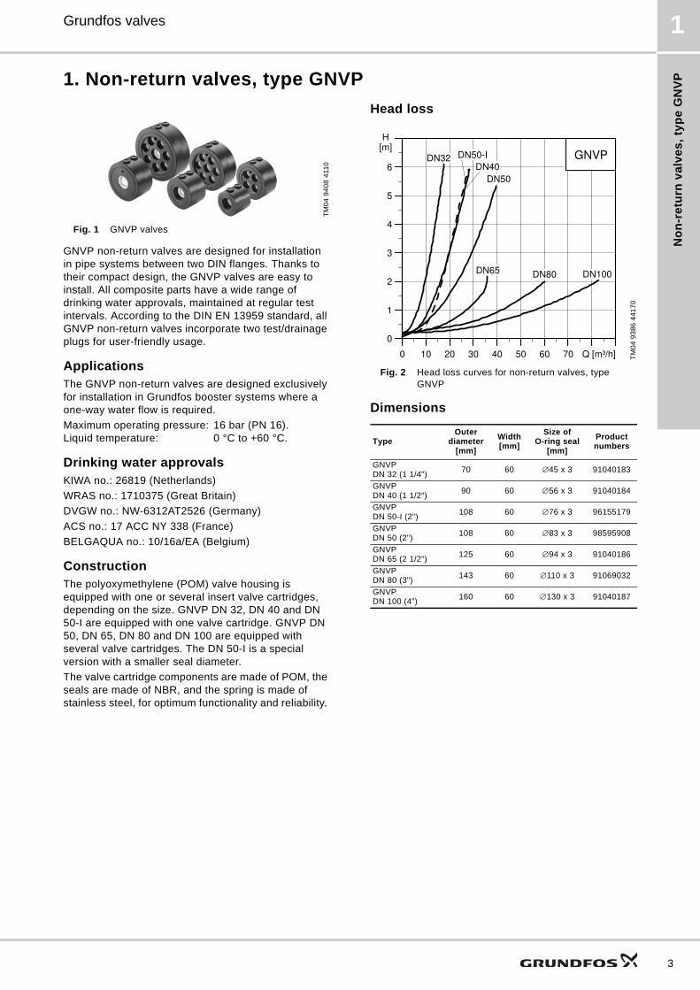
1. Non-return valves, type GNVP
Fig. 1 GNVP valves
GNVP non-return valves are designed for installation in pipe systems between two DIN flanges. Thanks to their compact design, the GNVP valves are easy to install. All composite parts have a wide range of drinking water approvals, maintained at regular test intervals. According to the DIN EN 13959 standard, all GNVP non-return valves incorporate two test/drainage plugs for user-friendly usage.
ApplicationsThe GNVP non-return valves are designed exclusively for installation in Grundfos booster systems where a one-way water flow is required.
Maximum operating pressure: 16 bar (PN 16).Liquid temperature: 0 °C to +60 °C.
Drinking water approvalsKIWA no.: 26819 (Netherlands)
WRAS no.: 1710375 (Great Britain)
DVGW no.: NW-6312AT2526 (Germany)
ACS no.: 17 ACC NY 338 (France)
BELGAQUA no.: 10/16a/EA (Belgium)
ConstructionThe polyoxymethylene (POM) valve housing is equipped with one or several insert valve cartridges, depending on the size. GNVP DN 32, DN 40 and DN 50-I are equipped with one valve cartridge. GNVP DN 50, DN 65, DN 80 and DN 100 are equipped with several valve cartridges. The DN 50-I is a special version with a smaller seal diameter.
The valve cartridge components are made of POM, the seals are made of NBR, and the spring is made of stainless steel, for optimum functionality and reliability.
Head loss
Fig. 2 Head loss curves for non-return valves, type GNVP
Dimensions
TM
04
94
08
411
0
TM
04
93
86
44
17
0
TypeOuter
diameter[mm]
Width[mm]
Size of O-ring seal
[mm]
Product numbers
GNVP DN 32 (1 1/4")
70 60 ∅45 x 3 91040183
GNVP DN 40 (1 1/2")
90 60 ∅56 x 3 91040184
GNVP DN 50-I (2")
108 60 ∅76 x 3 96155179
GNVP DN 50 (2")
108 60 ∅83 x 3 98595908
GNVP DN 65 (2 1/2")
125 60 ∅94 x 3 91040186
GNVP DN 80 (3")
143 60 ∅110 x 3 91069032
GNVP DN 100 (4")
160 60 ∅130 x 3 91040187
0 10 20 30 40 50 60 70 Q [m³/h]
0
1
2
3
4
5
6
[m]H
GNVPDN50-I
DN50
DN100DN80DN65
DN40DN32
3
No
n-re
turn
va
lve
s, ty
pe
GN
VP
4
Grundfos valves1
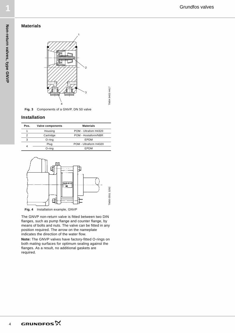
Materials
Fig. 3 Components of a GNVP, DN 50 valve
Installation
Fig. 4 Installation example, GNVP
The GNVP non-return valve is fitted between two DIN flanges, such as pump flange and counter flange, by means of bolts and nuts. The valve can be fitted in any position required. The arrow on the nameplate indicates the direction of the water flow.
Note: The GNVP valves have factory-fitted O-rings on both mating surfaces for optimum sealing against the flanges. As a result, no additional gaskets are required.
TM
04
94
03
44
17
Pos. Valve components Materials
1 Housing POM - Ultrafom H4320
2 Cartridge POM - Hostaform/NBR
3 O-ring EPDM
4Plug POM - Ultraform H4320
O-ring EPDM
TM
00
05
51
32
92
2
3
4
1
No
n-r
etu
rn v
alv
es
, ty
pe
GN
V
Grundfos valves 2
2. Non-return valves, type GNV
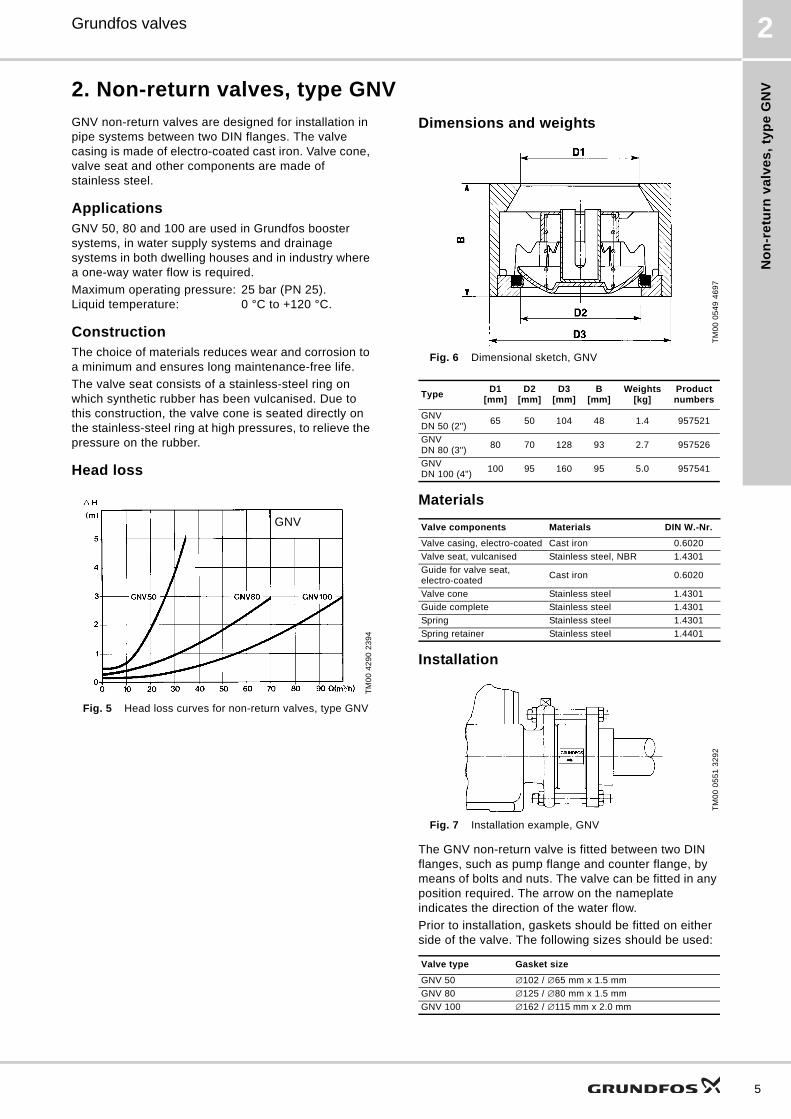
GNV non-return valves are designed for installation in pipe systems between two DIN flanges. The valve casing is made of electro-coated cast iron. Valve cone, valve seat and other components are made of stainless steel.
ApplicationsGNV 50, 80 and 100 are used in Grundfos booster systems, in water supply systems and drainage systems in both dwelling houses and in industry where a one-way water flow is required.
Maximum operating pressure: 25 bar (PN 25).Liquid temperature: 0 °C to +120 °C.
ConstructionThe choice of materials reduces wear and corrosion to a minimum and ensures long maintenance-free life.
The valve seat consists of a stainless-steel ring on which synthetic rubber has been vulcanised. Due to this construction, the valve cone is seated directly on the stainless-steel ring at high pressures, to relieve the pressure on the rubber.
Head loss
Fig. 5 Head loss curves for non-return valves, type GNV
Dimensions and weights
Fig. 6 Dimensional sketch, GNV
Materials
Installation
Fig. 7 Installation example, GNV
The GNV non-return valve is fitted between two DIN flanges, such as pump flange and counter flange, by means of bolts and nuts. The valve can be fitted in any position required. The arrow on the nameplate indicates the direction of the water flow.
Prior to installation, gaskets should be fitted on either side of the valve. The following sizes should be used:
TM
00
42
90
23
94
GNV
TM
00
05
49
46
97
TypeD1
[mm]D2
[mm]D3
[mm]B
[mm]Weights
[kg]Product numbers
GNV DN 50 (2")
65 50 104 48 1.4 957521
GNV DN 80 (3")
80 70 128 93 2.7 957526
GNV DN 100 (4")
100 95 160 95 5.0 957541
Valve components Materials DIN W.-Nr.
Valve casing, electro-coated Cast iron 0.6020
Valve seat, vulcanised Stainless steel, NBR 1.4301
Guide for valve seat, electro-coated
Cast iron 0.6020
Valve cone Stainless steel 1.4301
Guide complete Stainless steel 1.4301
Spring Stainless steel 1.4301
Spring retainer Stainless steel 1.4401
TM
00
05
51
32
92
Valve type Gasket size
GNV 50 ∅102 / ∅65 mm x 1.5 mm
GNV 80 ∅125 / ∅80 mm x 1.5 mm
GNV 100 ∅162 / ∅115 mm x 2.0 mm
5
Fo
ot v
alv
es
an
d n
on
-retu
rn v
alv
es
6
Grundfos valves3
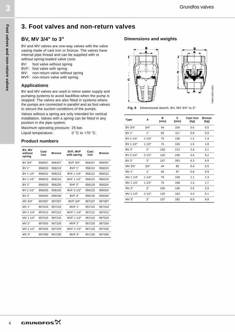
3. Foot valves and non-return valves
BV, MV 3/4" to 3"BV and MV valves are one-way valves with the valve casing made of cast iron or bronze. The valves have internal pipe thread and can be supplied with or without spring-loaded valve cone.
BV: foot valve without springBVF: foot valve with springMV: non-return valve without springMVF: non-return valve with spring.
ApplicationsBV and MV valves are used in minor water supply and pumping systems to avoid backflow when the pump is stopped. The valves are also fitted in systems where the pumps are connected in parallel and as foot valves to secure the suction conditions of the pumps.
Valves without a spring are only intended for vertical installation. Valves with a spring can be fitted in any position in the pipe system.
Maximum operating pressure: 25 bar.
Liquid temperature: 0 °C to +70 °C.
Product numbers
Dimensions and weights
Fig. 8 Dimensional sketch, BV, MV 3/4" to 3"
BV, MV without spring
Cast iron
BronzeBVF, MVF
with springCast iron
Bronze
BV 3/4" 956007 956207 BVF 3/4" 956107 956307
BV 1" 956010 956210 BVF 1" 956110 956310
BV 1 1/4" 956012 956212 BVF 1 1/4" 956112 956312
BV 1 1/2" 956015 956215 BVF 1 1/2" 956115 956315
BV 2" 956020 956220 BVF 2" 956120 956320
BV 2 1/2" 956025 956225 BVF 2 1/2" 956125 956325
BV 3" 956030 956230 BVF 3" 956130 956330
MV 3/4" 957007 957207 MVF 3/4" 957107 957307
MV 1" 957010 957210 MVF 1" 957110 957310
MV 1 1/4" 957012 957212 MVF 1 1/4" 957112 957312
MV 1 1/2" 957015 957215 MVF 1 1/2" 957115 957315
MV 2" 957020 957220 MVF 2" 957120 957320
MV 2 1/2" 957025 957225 MVF 2 1/2" 957125 957325
MV 3" 957030 957230 MVF 3" 957130 957330
TM
00
05
53
46
97
Type AB
[mm]C
[mm]Cast iron
[kg]Bronze
[kg]
BV 3/4" 3/4" 44 104 0.5 0.5
BV 1" 1" 60 117 0.8 0.9
BV 1 1/4" 1 1/4" 70 130 1.2 1.4
BV 1 1/2" 1 1/2" 75 155 1.5 1.8
BV 2" 2" 100 212 2.6 3.1
BV 2 1/2" 2 1/2" 120 235 4.6 5.2
BV 3" 3" 137 263 6.3 6.9
MV 3/4" 3/4" 44 80 0.4 0.5
MV 1" 1" 60 87 0.8 0.9
MV 1 1/4" 1 1/4" 70 100 1.1 1.3
MV 1 1/2" 1 1/2" 75 108 1.4 1.7
MV 2" 2" 100 136 2.5 2.9
MV 2 1/2" 2 1/2" 120 163 4.4 5.1
MV 3" 3" 137 182 6.0 6.8

Fo
ot
va
lve
s a
nd
no
n-r
etu
rn v
alv
es
Grundfos valves 3
Head loss without spring
Fig. 9 Head loss curves for BV and MV
Head loss with spring
Fig. 10 Head loss curves for BVF and MVF
Materials
BV, MV 4" to 6"BV and MV valves are one-way valves with valve casing in stainless steel or nickel-resist alloy and other components in stainless steel. Foot valves (BV) in stainless steel are only available in the 6" dimension.
BV 4" to 6" in nickel-resist alloyMV 4" to 6" in nickel-resist alloyBV 6" in stainless steel.
ApplicationsThe foot valve is fitted to the inlet pipe in boreholes to secure the suction condition of the pump.
The non-return valve is fitted in large pipe systems to avoid back flow, etc.
Thanks to the combination of materials, the BV and MV valves can be used in pipe systems for slightly aggressive liquids.
Maximum operating pressure: 25 bar.Liquid temperature: 0 °C to +70 °C.
Head loss
Fig. 11 Head loss curves for BV and MV
TM
00
11
92
46
97
TM
00
11
93
46
97
Valve components Materials DIN W.-Nr.
Valve casingCast iron 0.6020
Bronze 2.1176.01
Valve seat, vulcanised Stainless steel, NBR 1.4301
Valve cone, vulcanised Stainless steel, NBR 1.4301
Spring Stainless steel 1.4301
Spring retainer Stainless steel 1.4301
Nipple (MV) Bronze 2.1096.01
Strainer (BV) Bronze 2.1096.01
TM
00
70
22
03
96
0 20 40 60 80 100 120 140 160 Q [m /h]
0.0
0.5
1.0
1.5
2.0
2.5
3.0
3.5
4.0
4.5
H [m]
6"
4" & 5"
7
Fo
ot v
alv
es
an
d n
on
-retu
rn v
alv
es
8
Grundfos valves3
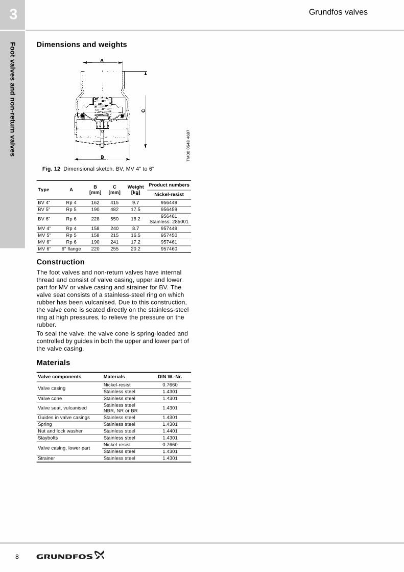
Dimensions and weights
Fig. 12 Dimensional sketch, BV, MV 4" to 6"
ConstructionThe foot valves and non-return valves have internal thread and consist of valve casing, upper and lower part for MV or valve casing and strainer for BV. The valve seat consists of a stainless-steel ring on which rubber has been vulcanised. Due to this construction, the valve cone is seated directly on the stainless-steel ring at high pressures, to relieve the pressure on the rubber.
To seal the valve, the valve cone is spring-loaded and controlled by guides in both the upper and lower part of the valve casing.
Materials
TM
00
05
48
46
97
Type AB
[mm]C
[mm]Weight
[kg]
Product numbers
Nickel-resist
BV 4" Rp 4 162 415 9.7 956449
BV 5" Rp 5 190 482 17.5 956459
BV 6" Rp 6 228 550 18.2956461
Stainless: 285001
MV 4" Rp 4 158 240 8.7 957449
MV 5" Rp 5 158 215 16.5 957450
MV 6" Rp 6 190 241 17.2 957461
MV 6" 6" flange 220 255 20.2 957460
Valve components Materials DIN W.-Nr.
Valve casingNickel-resist 0.7660
Stainless steel 1.4301
Valve cone Stainless steel 1.4301
Valve seat, vulcanisedStainless steelNBR, NR or BR
1.4301
Guides in valve casings Stainless steel 1.4301
Spring Stainless steel 1.4301
Nut and lock washer Stainless steel 1.4401
Staybolts Stainless steel 1.4301
Valve casing, lower partNickel-resist 0.7660
Stainless steel 1.4301
Strainer Stainless steel 1.4301
Gru
nd
fos
Pro
du
ct
Ce
nte
r
9
Grundfos valves 4
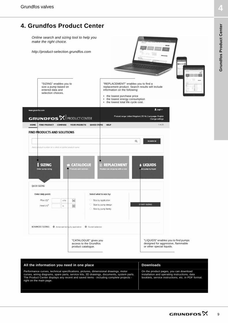
4. Grundfos Product Center
All the information you need in one place Downloads
Performance curves, technical specifications, pictures, dimensional drawings, motor curves, wiring diagrams, spare parts, service kits, 3D drawings, documents, system parts. The Product Center displays any recent and saved items - including complete projects - right on the main page.
On the product pages, you can download installation and operating instructions, data booklets, service instructions, etc. in PDF format.
"SIZING" enables you to size a pump based on entered data and selection choices.
Online search and sizing tool to help you make the right choice.
http://product-selection.grundfos.com
"REPLACEMENT" enables you to find a replacement product. Search results will include information on the following:
• the lowest purchase price• the lowest energy consumption• the lowest total life cycle cost.
"CATALOGUE" gives you access to the Grundfos product catalogue.
"LIQUIDS" enables you to find pumps designed for aggressive, flammable or other special liquids.
10

11
GRUNDFOS A/S DK-8850 Bjerringbro . DenmarkTelephone: +45 87 50 14 00www.grundfos.com
V7048838 1217
ECM: 1216119 Th
e n
am
e G
run
dfo
s, t
he
Gru
nd
fos
log
o,
an
d b
e t
hin
k i
nn
ov
ate
are
re
gis
tere
d t
rad
em
ark
s o
wn
ed
by
Gru
nd
fos
Ho
ldin
g A
/S o
r G
run
dfo
s A
/S,
De
nm
ark
. A
ll ri
gh
ts r
ese
rve
d w
orl
dw
ide
.©
Co
pyr
igh
t G
run
dfo
s H
old
ing
A/S


![Grundfos SL1.50.65.22.2.50D.C pump - Lenntech › uploads › grundfos › 98624257 › ...Printed from Grundfos Product Centre [2018.06.003] Position Qty. Description 1 SL1.50.65.22.2.50D.C](https://img.pdfslide.us/doc/110x75/60ce95cbe9a1406f7c619e35/grundfos-sl1506522250dc-pump-lenntech-a-uploads-a-grundfos-a-98624257.jpg)