Embed Size (px)
Citation preview

DKM-411 User Manual Rev_01 Firmware V-1.0
DKM-411
ADVANCED
NETWORK
ANALYSER WITH
INTERNET
COMMUNICATIONS
The DKM-411 is an advanced precision metering device offering an 3.5” size, 320x240 pixel color TFT, together with unrivalled remote monitoring capabilities over internet in a compact and low cost package.
The unit itself is a web page and can be opened through any browser for remote monitoring.
The central monitoring feature allows monitoring of thousands of meters from one central PC.
The unit complies and mostly exceeds world’s tightest safety, EMC and environmental standards for the industrial category.
Software features are complete with easy firmware upgrade process through USB port.
The Windows based PC software allows monitoring and programming through USB, RS-485, Ethernet and GPRS.
The PC based Rainbow Scada software allows monitoring and control of an unlimited number of devices from a single central location.
Ethernet 10/100Mb RS-485 isolated (Modbus RTU) RS-232 for external GPRS modem USB Host for data recording on flash memory USB Device for PC connection
True RMS measurements
3.5” TFT LCD, 320x240 pixels
Internal battery backed-up real time clock
Harmonic distortion display (63 harmonics)
Oscilloscope, waveform display
Phasor diagram display
Max demand display
User configurable display screens
2 configurable relay outputs
Free internet based monitoring program
2 opto-isolated, configurable digital inputs
Dual active-reactive power counters
Both mains & generator energy metering
Configurable user counters
Voltage transformer ratio for MV applications
Password protected front panel programming
Reduced panel depth
Sealed front panel (IP54)
3 phases 4 wires, star 3 phases 3 wires, 3 CTs 3 phases 3 wires, 2 CTs (L1-L2) 3 phases 3 wires, 2 CTs (L1-L3) 3 phases 4 wires, delta 2 phases 3 wires, L1-L2 1 phase 2 wires
COMMUNICATION PORTS
FEATURES
TOPOLOGIES
DESCRIPTION
DKM-411 User Manual Rev_01 Firmware V-1.0
K46D03-EN - 2 -
Any unauthorized use or copying of the contents or any part of this document is prohibited. This applies in particular to trademarks, model denominations, part numbers and drawings.
This document describes minimum requirements and necessary steps for the successful installation of the DKM-411 family units.
Follow carefully advices given in the document. These are often good practices for the installation of genset control units which reduce future issues.
For all technical queries please contact Datakom at below e-mail address:
If additional information to this manual is required, please contact the manufacturer directly at below e-mail address:
Please provide following information in order to get answers to any question:
- Device model name (see the back panel of the unit), - Complete serial number (see the back panel of the unit), - Firmware version (read from the display screen), - Measuring-circuit voltage and power supply voltage, - Precise description of the querry.
REV. DATE AUTHOR DESCRIPTION
01 04-12-2012 MH First issue
QUERRIES
REVISION HISTORY
ABOUT THIS DOCUMENT
COPYRIGHT NOTICE
DKM-411 User Manual Rev_01 Firmware V-1.0
K46D03-EN - 3 -
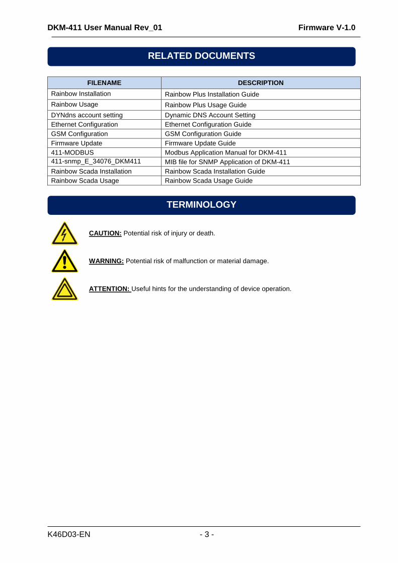
FILENAME DESCRIPTION
Rainbow Installation Rainbow Plus Installation Guide
Rainbow Usage Rainbow Plus Usage Guide
DYNdns account setting Dynamic DNS Account Setting
Ethernet Configuration Ethernet Configuration Guide
GSM Configuration GSM Configuration Guide
Firmware Update Firmware Update Guide
411-MODBUS Modbus Application Manual for DKM-411
411-snmp_E_34076_DKM411 MIB file for SNMP Application of DKM-411
Rainbow Scada Installation Rainbow Scada Installation Guide
Rainbow Scada Usage Rainbow Scada Usage Guide
CAUTION: Potential risk of injury or death.
WARNING: Potential risk of malfunction or material damage.
ATTENTION: Useful hints for the understanding of device operation.
RELATED DOCUMENTS
TERMINOLOGY
DKM-411 User Manual Rev_01 Firmware V-1.0
K46D03-EN - 4 -
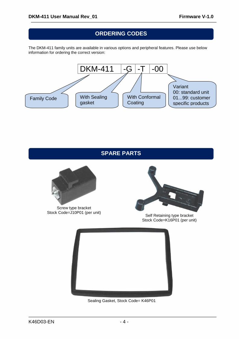
The DKM-411 family units are available in various options and peripheral features. Please use below information for ordering the correct version:
DKM-411 -G -T -00
Screw type bracket
Stock Code=J10P01 (per unit) Self Retaining type bracket
Stock Code=K16P01 (per unit)
Sealing Gasket, Stock Code= K46P01
SPARE PARTS
ORDERING CODES
Family Code With Sealing gasket
With Conformal Coating
Variant 00: standard unit 01...99: customer specific products
DKM-411 User Manual Rev_01 Firmware V-1.0
K46D03-EN - 5 -
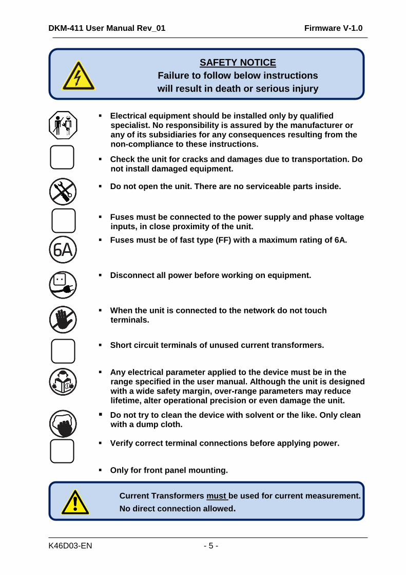
Electrical equipment should be installed only by qualified specialist. No responsibility is assured by the manufacturer or any of its subsidiaries for any consequences resulting from the non-compliance to these instructions.
Check the unit for cracks and damages due to transportation. Do not install damaged equipment.
Do not open the unit. There are no serviceable parts inside.
Fuses must be connected to the power supply and phase voltage inputs, in close proximity of the unit.
Fuses must be of fast type (FF) with a maximum rating of 6A.
Disconnect all power before working on equipment.
When the unit is connected to the network do not touch terminals.
Short circuit terminals of unused current transformers.
Any electrical parameter applied to the device must be in the range specified in the user manual. Although the unit is designed with a wide safety margin, over-range parameters may reduce lifetime, alter operational precision or even damage the unit.
Do not try to clean the device with solvent or the like. Only clean with a dump cloth.
Verify correct terminal connections before applying power.
Only for front panel mounting.
SAFETY NOTICE
Failure to follow below instructions
will result in death or serious injury
Current Transformers must be used for current measurement.
No direct connection allowed.
DKM-411 User Manual Rev_01 Firmware V-1.0
K46D03-EN - 6 -
1.INSTALLATION INSTRUCTIONS 2.MOUNTING
2.1. DIMENSIONS 2.2. SEALING, GASKET 2.3. ELECTRICAL INSTALLATION
3. TERMINAL DESCRIPTIONS 3.1. AUXILIARY SUPPLY INPUT 3.2. AC VOLTAGE INPUTS 3.3. AC CURRENT INPUTS 3.4. DIGITAL INPUTS 3.5. DIGITAL OUTPUTS 3.6. RS-485 PORT 3.7. ETHERNET PORT 3.8. USB DEVICE PORT 3.9. USB HOST PORT 3.10. MODEM PORT 3.11. EXTERNAL GSM MODEM (DKG-090)
4. TOPOLOGIES 4.1. SELECTING THE TOPOLOGY 4.2. 3 PHASE, 4 WIRE, STAR 4.3. 3 PHASE, 3 WIRE, DELTA 4.4. 3 PHASE, 4 WIRE, DELTA 4.5. 3 PHASE, 3 WIRE, DELTA, 2 CT (L1-L2) 4.6. 3 PHASE, 3 WIRE, DELTA, 2 CT (L1-L3) 4.7. 2 PHASE, 3 WIRE, DELTA, 2 CTs (L1-L2)
5. CONNECTION DIAGRAM 6. TERMINAL DESCRIPTION 7. TECHNICAL SPECIFICATIONS 8. DESCRIPTION OF CONTROLS
8.1. FRONT PANEL FUNCTIONALITY 8.2. PUSHBUTTON FUNCTIONS 8.3. DISPLAY SCREEN ORGANIZATION 8.4. MEASURED PARAMETERS
9. WAVEFORM DISPLAY & HARMONIC ANALYSIS 10. PHASOR DIAGRAM 11. ANALOG DISPLAYS 12. COMPARING MEASUREMENTS 13. USER CONFIGURABLE DISPLAY SCREENS 14. POWER COUNTERS & INCREMENTAL COUNTERS 15. DEMAND VALUES 16. MIN-MAX VALUES 17. DISPLAYING EVENT LOGS 18. PROTECTIONS AND ALARMS
TABLE OF CONTENTS
DKM-411 User Manual Rev_01 Firmware V-1.0
K46D03-EN - 7 -
19. PROGRAMMING 19.1. ENTERING THE PROGRAMMING MODE 19.2. NAVIGATING BETWEEN MENUS 19.3. MODIFYING PARAMETER VALUE 19.4. PROGRAMMING MODE EXIT 19.5. RESETTING TO FACTORY SET PARAMETERS
20. PROGRAM PARAMETER LIST 20.1. CONTROLLER CONFIGURATION GROUP 20.2. ELECTRICAL PARAMETERS GROUP 20.3. COUNTERS MIN/MAX PARAMETERS GROUP 20.4. DIGITAL INPUT CONFIGURATION 20.5. OUTPUT CONFIGURATION 20.6. USER INPUT STRINGS 20.7. CONFIGURING USER DISPLAY SCREENS 20.8. SITE-ID STRING 20.9. DEVICE SERIAL NUMBER 20.10. SMS1-2-3-4 TELEPHONE NUMBERS 20.11. ADJUST DATE AND TIME 20.12. GSM MODEM PARAMETERS 20.13. ETHERNET PARAMETERS
21. ETHERNET CONFIGURATION 22. GSM CONFIGURATION 23. DYNAMIC DNS FEATURE 24. ACCESSING THE EMBEDDED WEB SERVER 25. WEB MONITORING 26. CENTRAL MONITORING 27. E-MAIL SENDING 28. ETHERNET/GPRS – MODBUS GATEWAY OPERATION 29. SMS COMMANDS 30. DATA RECORDING
30.1. DATA RECORDING MEDIA 30.2. DIRECTORY STRUCTURE 30.3. UNDERSTANDING THE CSV FORMAT 30.4. RECORDED DATA LIST, RECORD PERIOD
31. MODBUS COMMUNICATIONS 31.1. PARAMETERS REQUIRED FOR RS-485 MODBUS OPERATION 31.2. PARAMETERS REQUIRED FOR MODBUS-TCP/IP VIA ETHERNET 31.3. DATA FORMATS
32. SNMP COMMUNICATIONS 32.1. PARAMETERS REQUIRED FOR SNMP VIA ETHERNET
33. CALIBRATION 34. DECLARATION OF CONFORMITY 35. MAINTENANCE 36. DISPOSAL OF THE UNIT 37. ROHS COMPLIANCE 38. TROUBLESHOOTING GUIDE
DKM-411 User Manual Rev_01 Firmware V-1.0
K46D03-EN - 8 -
Before installation:
Read the user manual carefully, determine the correct connection diagram.
Remove all connectors and mounting brackets from the unit, then pass the unit through the mounting opening.
Put mounting brackets and tighten. Do not tighten too much, this can brake the enclosure.
Make electrical connections with plugs removed from sockets, then place plugs to their sockets.
Be sure that adequate cooling is provided.
Be sure that the temperature of the environment will not exceed the maximum operating temperature in any case.
Below conditions may damage the device:
Incorrect connections.
Incorrect power supply voltage.
Voltage at measuring terminals beyond specified range.
Voltage applied to digital inputs over specified range.
Current at measuring terminals beyond specified range.
Overload or short circuit at relay outputs
Connecting or removing data terminals when the unit is powered-up.
High voltage applied to communication ports.
Ground potential differences at non-isolated communication ports. (USB, RS-232)
Excessive vibration, direct installation on vibrating parts.
Below conditions may cause abnormal operation:
Power supply voltage below minimum acceptable level.
Power supply frequency out of specified limits
Phase order of voltage inputs not correct.
Current transformers not matching related phases.
Current transformer polarity incorrect.
Current Transformers must be used for current measurement.
No direct connection allowed.
1. INSTALLATION INSTRUCTIONS
DKM-411 User Manual Rev_01 Firmware V-1.0
K46D03-EN - 9 -
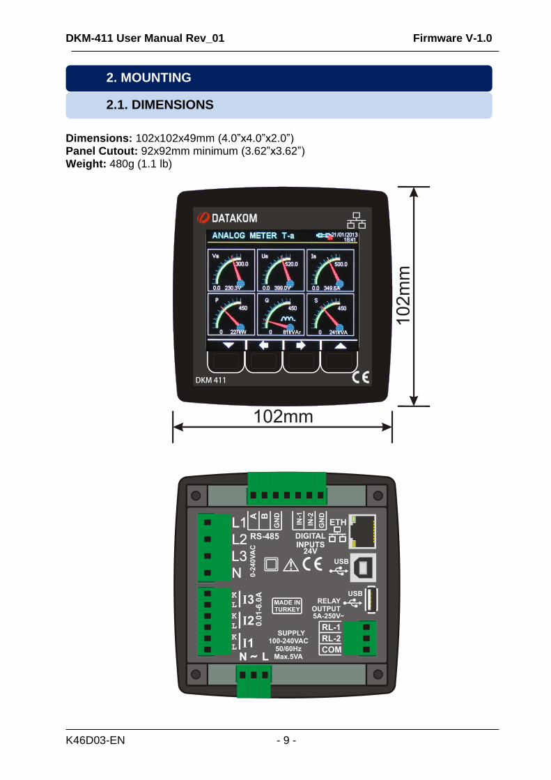
Dimensions: 102x102x49mm (4.0”x4.0”x2.0”) Panel Cutout: 92x92mm minimum (3.62”x3.62”) Weight: 480g (1.1 lb)
2.1. DIMENSIONS
2. MOUNTING
DKM-411 User Manual Rev_01 Firmware V-1.0
K46D03-EN - 10 -
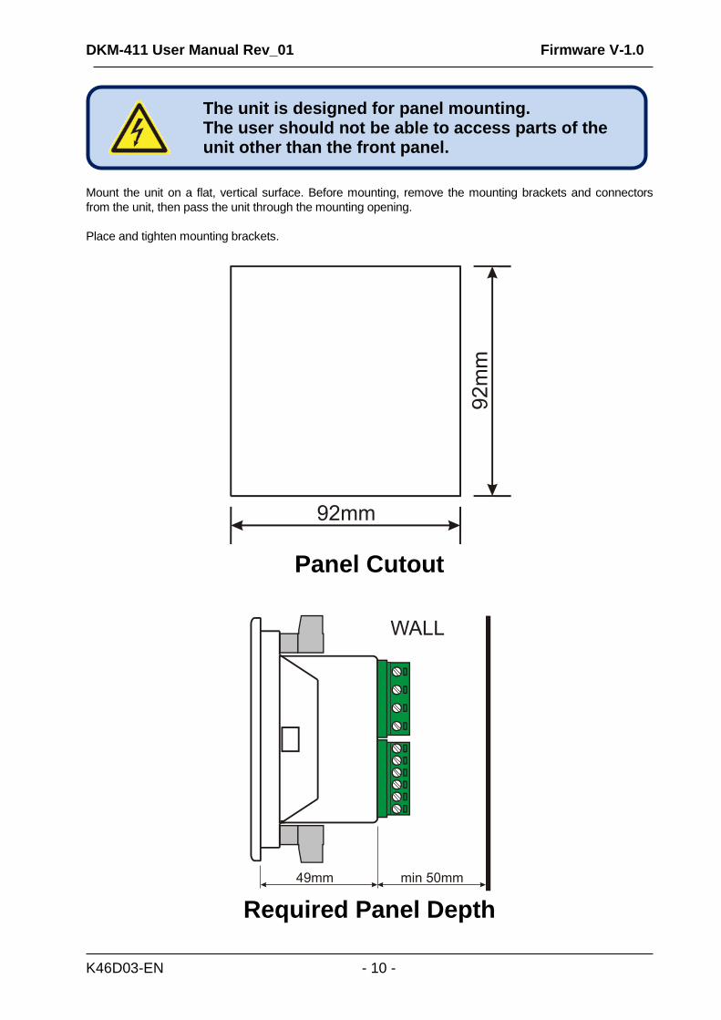
Mount the unit on a flat, vertical surface. Before mounting, remove the mounting brackets and connectors
from the unit, then pass the unit through the mounting opening.
Place and tighten mounting brackets.
Panel Cutout
Required Panel Depth
The unit is designed for panel mounting. The user should not be able to access parts of the unit other than the front panel.

DKM-411 User Manual Rev_01 Firmware V-1.0
K46D03-EN - 11 -
Two different types of brackets are provided:
Screw type bracket
Self retaining type bracket
Installation of screw type bracket
Installation of self retaining type bracket
Do not tighten too much, this may break the unit.
DKM-411 User Manual Rev_01 Firmware V-1.0
K46D03-EN - 12 -
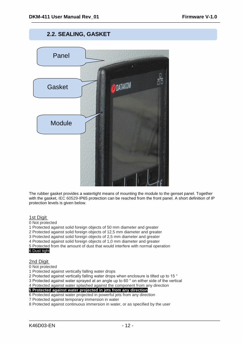
The rubber gasket provides a watertight means of mounting the module to the genset panel. Together with the gasket, IEC 60529-IP65 protection can be reached from the front panel. A short definition of IP protection levels is given below.
1st Digit Description of Protection Level 0 Not protected 1 Protected against solid foreign objects of 50 mm diameter and greater 2 Protected against solid foreign objects of 12,5 mm diameter and greater 3 Protected against solid foreign objects of 2,5 mm diameter and greater 4 Protected against solid foreign objects of 1,0 mm diameter and greater 5 Protected from the amount of dust that would interfere with normal operation 6 Dust tight
2nd Digit Description of Protection Level 0 Not protected 1 Protected against vertically falling water drops 2 Protected against vertically falling water drops when enclosure is tilted up to 15 ° 3 Protected against water sprayed at an angle up to 60 ° on either side of the vertical 4 Protected against water splashed against the component from any direction 5 Protected against water projected in jets from any direction 6 Protected against water projected in powerful jets from any direction 7 Protected against temporary immersion in water 8 Protected against continuous immersion in water, or as specified by the user
2.2. SEALING, GASKET
Module
Gasket
Panel
DKM-411 User Manual Rev_01 Firmware V-1.0
K46D03-EN - 13 -
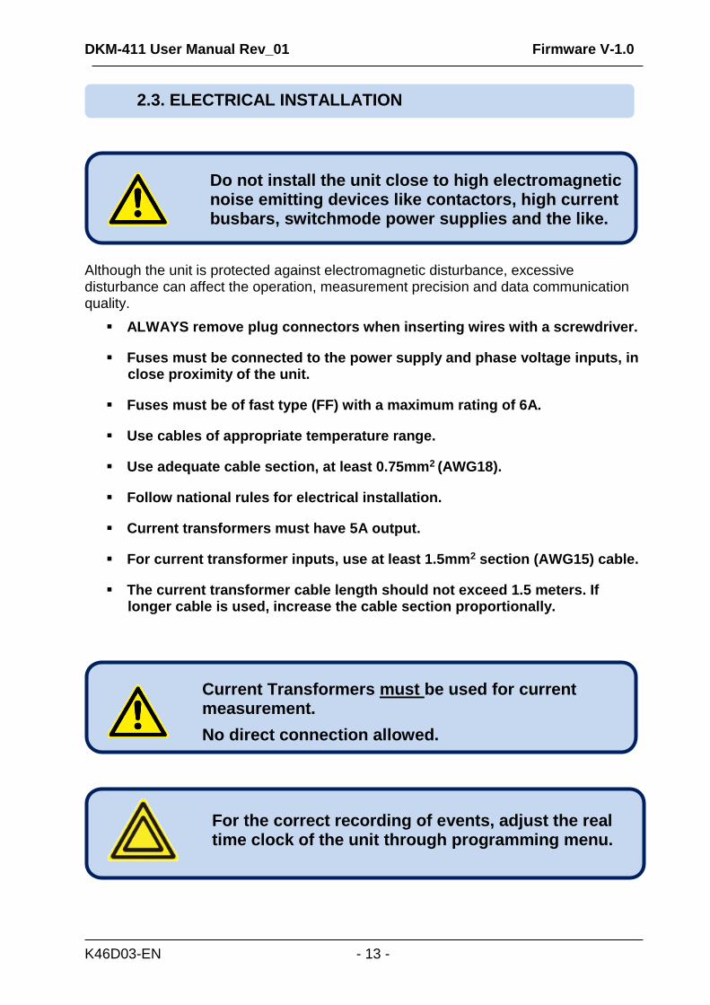
Although the unit is protected against electromagnetic disturbance, excessive disturbance can affect the operation, measurement precision and data communication quality.
ALWAYS remove plug connectors when inserting wires with a screwdriver.
Fuses must be connected to the power supply and phase voltage inputs, in close proximity of the unit.
Fuses must be of fast type (FF) with a maximum rating of 6A.
Use cables of appropriate temperature range.
Use adequate cable section, at least 0.75mm2 (AWG18).
Follow national rules for electrical installation.
Current transformers must have 5A output.
For current transformer inputs, use at least 1.5mm2 section (AWG15) cable.
The current transformer cable length should not exceed 1.5 meters. If longer cable is used, increase the cable section proportionally.
For the correct recording of events, adjust the real time clock of the unit through programming menu.
Current Transformers must be used for current measurement.
No direct connection allowed.
Do not install the unit close to high electromagnetic noise emitting devices like contactors, high current busbars, switchmode power supplies and the like.
2.3. ELECTRICAL INSTALLATION
DKM-411 User Manual Rev_01 Firmware V-1.0
K46D03-EN - 14 -
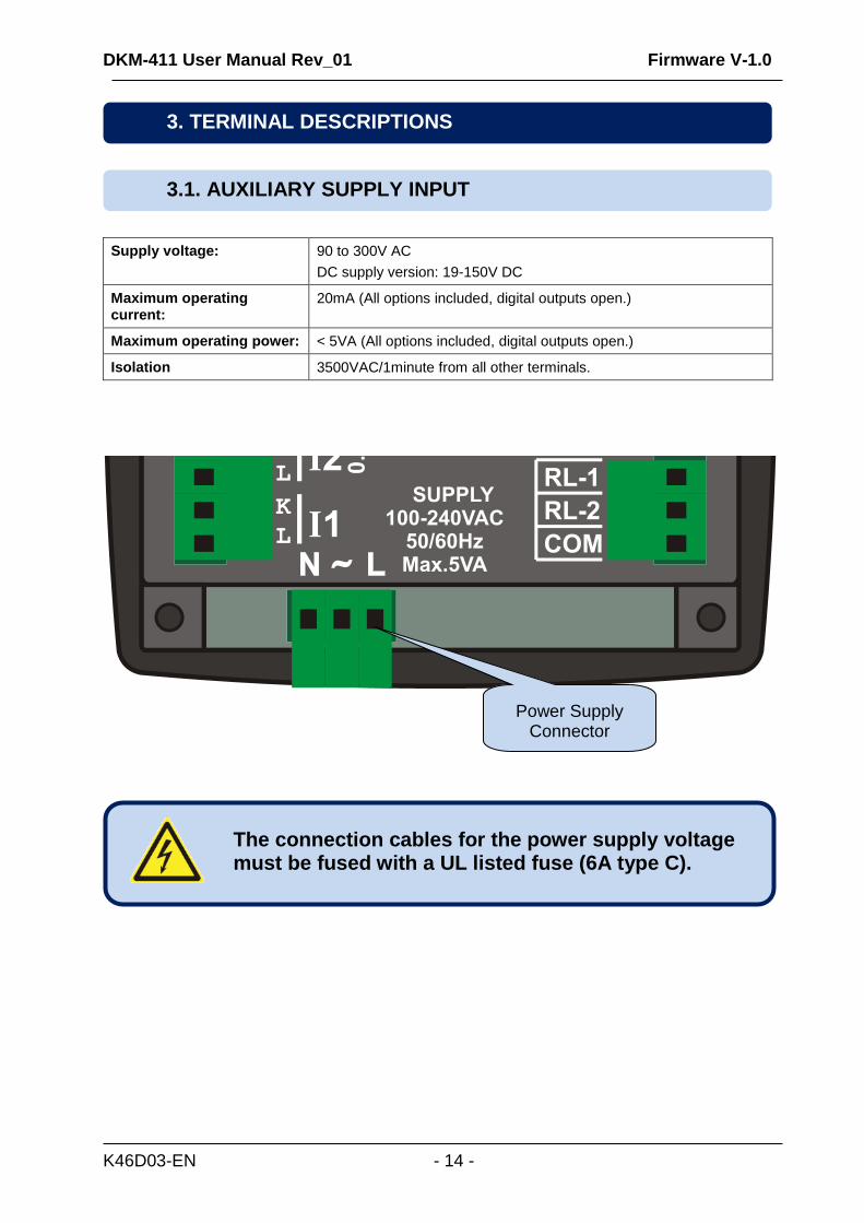
Supply voltage: 90 to 300V AC
DC supply version: 19-150V DC
Maximum operating current:
20mA (All options included, digital outputs open.)
Maximum operating power: < 5VA (All options included, digital outputs open.)
Isolation 3500VAC/1minute from all other terminals.
The connection cables for the power supply voltage must be fused with a UL listed fuse (6A type C).
3.1. AUXILIARY SUPPLY INPUT
3. TERMINAL DESCRIPTIONS
Power Supply Connector
DKM-411 User Manual Rev_01 Firmware V-1.0
K46D03-EN - 15 -
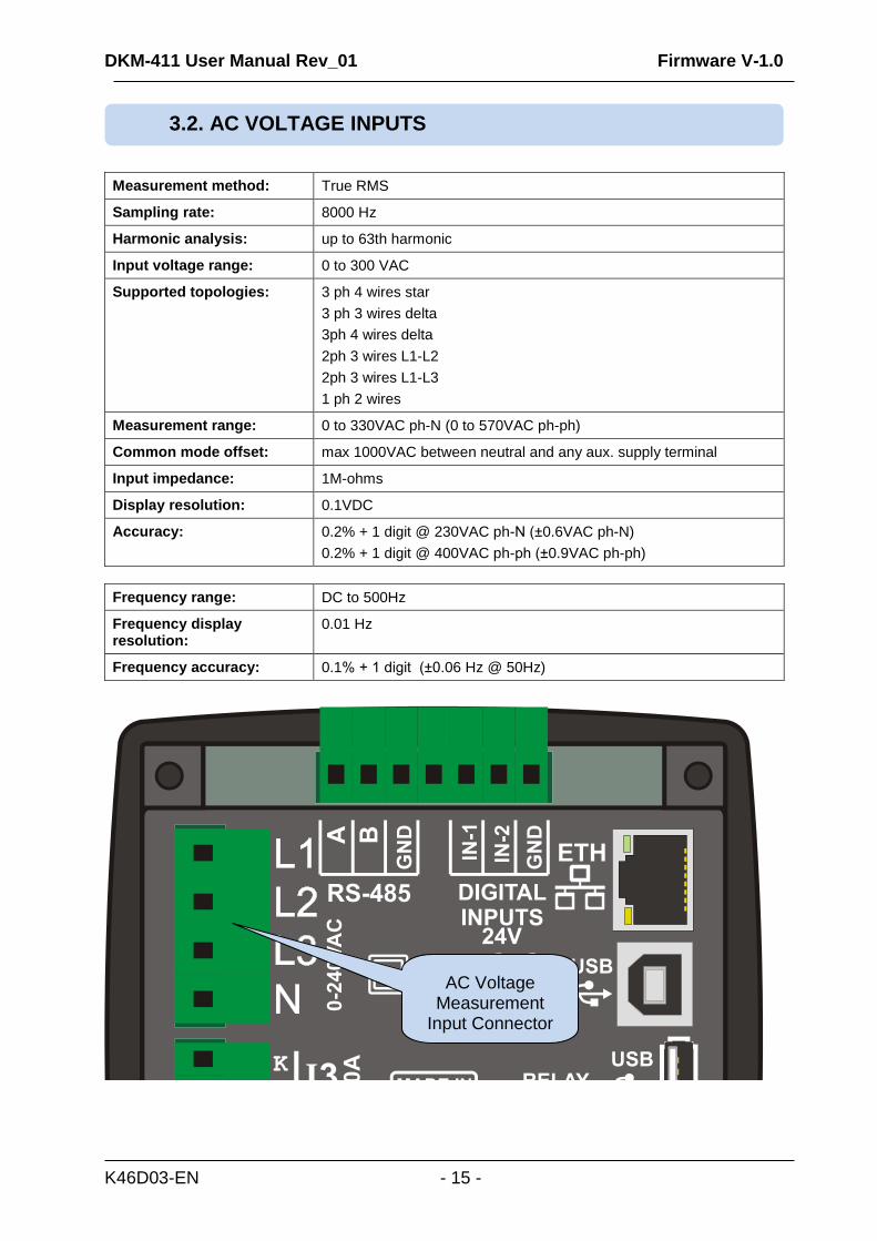
Measurement method: True RMS
Sampling rate: 8000 Hz
Harmonic analysis: up to 63th harmonic
Input voltage range: 0 to 300 VAC
Supported topologies: 3 ph 4 wires star
3 ph 3 wires delta
3ph 4 wires delta
2ph 3 wires L1-L2
2ph 3 wires L1-L3
1 ph 2 wires
Measurement range: 0 to 330VAC ph-N (0 to 570VAC ph-ph)
Common mode offset: max 1000VAC between neutral and any aux. supply terminal
Input impedance: 1M-ohms
Display resolution: 0.1VDC
Accuracy: 0.2% + 1 digit @ 230VAC ph-N (±0.6VAC ph-N)
0.2% + 1 digit @ 400VAC ph-ph (±0.9VAC ph-ph)
Frequency range: DC to 500Hz
Frequency display resolution:
0.01 Hz
Frequency accuracy: 0.1% + 1 digit (±0.06 Hz @ 50Hz)
3.2. AC VOLTAGE INPUTS
AC Voltage Measurement
Input Connector
DKM-411 User Manual Rev_01 Firmware V-1.0
K46D03-EN - 16 -
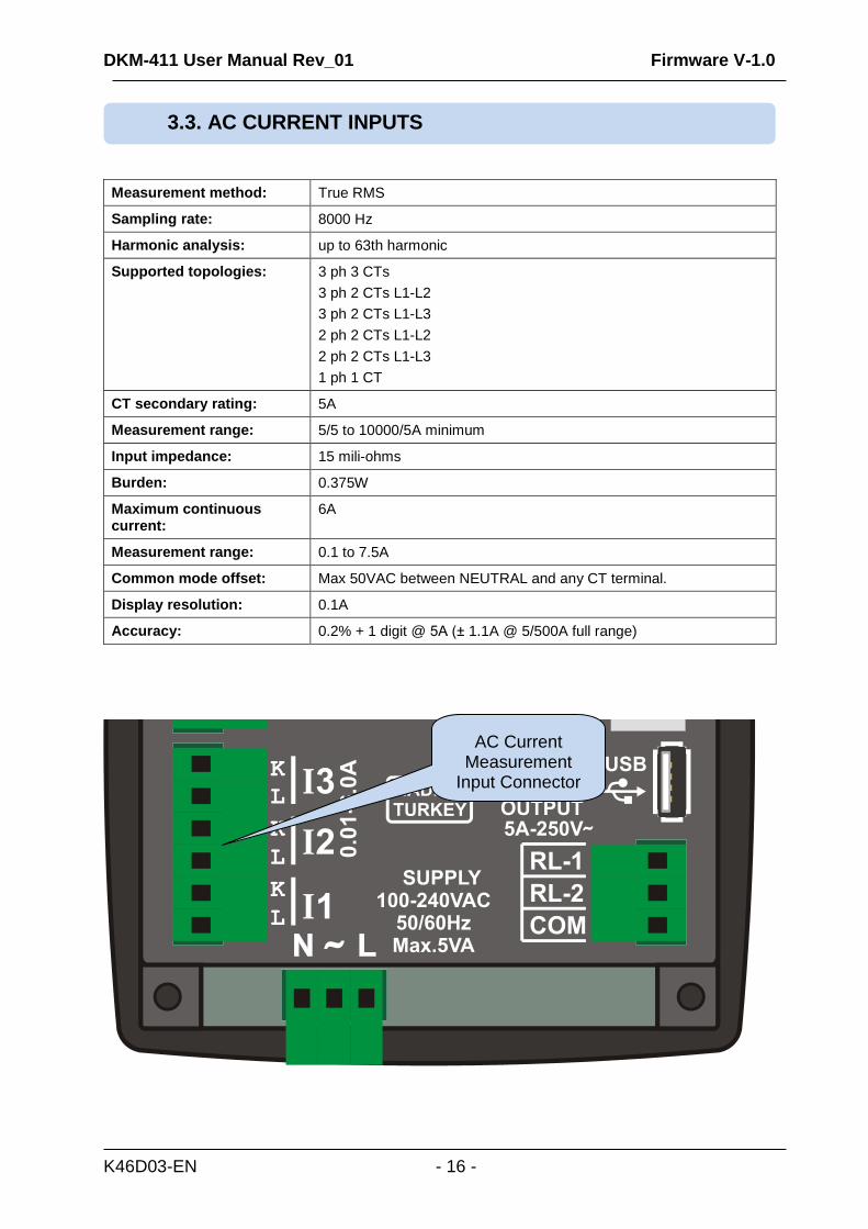
Measurement method: True RMS
Sampling rate: 8000 Hz
Harmonic analysis: up to 63th harmonic
Supported topologies: 3 ph 3 CTs
3 ph 2 CTs L1-L2
3 ph 2 CTs L1-L3
2 ph 2 CTs L1-L2
2 ph 2 CTs L1-L3
1 ph 1 CT
CT secondary rating: 5A
Measurement range: 5/5 to 10000/5A minimum
Input impedance: 15 mili-ohms
Burden: 0.375W
Maximum continuous current:
6A
Measurement range: 0.1 to 7.5A
Common mode offset: Max 50VAC between NEUTRAL and any CT terminal.
Display resolution: 0.1A
Accuracy: 0.2% + 1 digit @ 5A (± 1.1A @ 5/500A full range)
3.3. AC CURRENT INPUTS
AC Current Measurement
Input Connector
DKM-411 User Manual Rev_01 Firmware V-1.0
K46D03-EN - 17 -
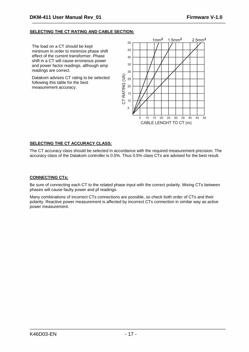
SELECTING THE CT RATING AND CABLE SECTION:
The load on a CT should be kept minimum in order to minimize phase shift effect of the current transformer. Phase shift in a CT will cause erroneous power and power factor readings, although amp readings are correct.
Datakom advises CT rating to be selected following this table for the best measurement accuracy.
SELECTING THE CT ACCURACY CLASS:
The CT accuracy class should be selected in accordance with the required measurement precision. The accuracy class of the Datakom controller is 0.5%. Thus 0.5% class CTs are advised for the best result.
CONNECTING CTs:
Be sure of connecting each CT to the related phase input with the correct polarity. Mixing CTs between phases will cause faulty power and pf readings.
Many combinations of incorrect CTs connections are possible, so check both order of CTs and their polarity. Reactive power measurement is affected by incorrect CTs connection in similar way as active power measurement.
DKM-411 User Manual Rev_01 Firmware V-1.0
K46D03-EN - 18 -
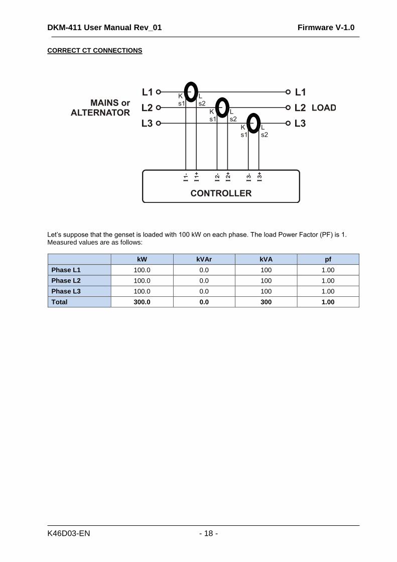
CORRECT CT CONNECTIONS
Let’s suppose that the genset is loaded with 100 kW on each phase. The load Power Factor (PF) is 1. Measured values are as follows:
kW kVAr kVA pf
Phase L1 100.0 0.0 100 1.00
Phase L2 100.0 0.0 100 1.00
Phase L3 100.0 0.0 100 1.00
Total 300.0 0.0 300 1.00
DKM-411 User Manual Rev_01 Firmware V-1.0
K46D03-EN - 19 -
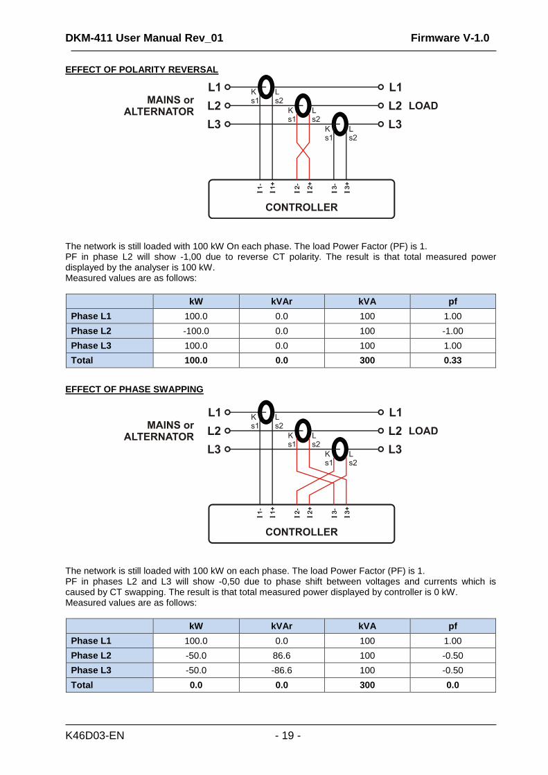
EFFECT OF POLARITY REVERSAL
The network is still loaded with 100 kW On each phase. The load Power Factor (PF) is 1. PF in phase L2 will show -1,00 due to reverse CT polarity. The result is that total measured power displayed by the analyser is 100 kW. Measured values are as follows:
kW kVAr kVA pf
Phase L1 100.0 0.0 100 1.00
Phase L2 -100.0 0.0 100 -1.00
Phase L3 100.0 0.0 100 1.00
Total 100.0 0.0 300 0.33
EFFECT OF PHASE SWAPPING
The network is still loaded with 100 kW on each phase. The load Power Factor (PF) is 1. PF in phases L2 and L3 will show -0,50 due to phase shift between voltages and currents which is caused by CT swapping. The result is that total measured power displayed by controller is 0 kW. Measured values are as follows:
kW kVAr kVA pf
Phase L1 100.0 0.0 100 1.00
Phase L2 -50.0 86.6 100 -0.50
Phase L3 -50.0 -86.6 100 -0.50
Total 0.0 0.0 300 0.0
DKM-411 User Manual Rev_01 Firmware V-1.0
K46D03-EN - 20 -
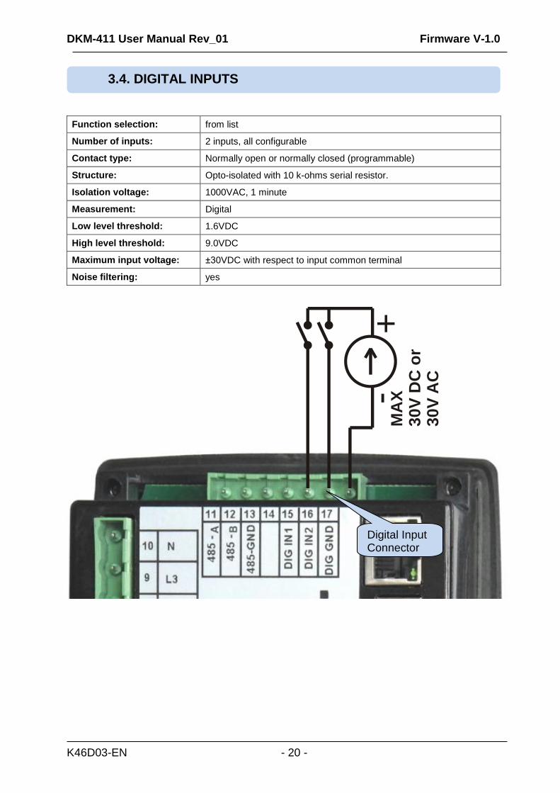
Function selection: from list
Number of inputs: 2 inputs, all configurable
Contact type: Normally open or normally closed (programmable)
Structure: Opto-isolated with 10 k-ohms serial resistor.
Isolation voltage: 1000VAC, 1 minute
Measurement: Digital
Low level threshold: 1.6VDC
High level threshold: 9.0VDC
Maximum input voltage: ±30VDC with respect to input common terminal
Noise filtering: yes
3.4. DIGITAL INPUTS
Digital Input Connector
MA
X
30V
DC
or
30V
AC
-+
DKM-411 User Manual Rev_01 Firmware V-1.0
K46D03-EN - 21 -
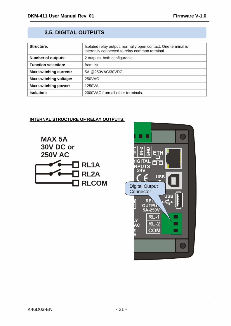
Structure: Isolated relay output, normally open contact. One terminal is internally connected to relay common terminal
Number of outputs: 2 outputs, both configurable
Function selection: from list
Max switching current: 5A @250VAC/30VDC
Max switching voltage: 250VAC
Max switching power: 1250VA
Isolation: 2000VAC from all other terminals.
INTERNAL STRUCTURE OF RELAY OUTPUTS:
MAX 5A 30V DC or250V AC
RL1A
RL2A
RLCOM
3.5. DIGITAL OUTPUTS
Digital Output Connector
DKM-411 User Manual Rev_01 Firmware V-1.0
K46D03-EN - 22 -
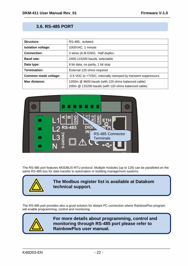
Structure: RS-485, isolated.
Isolation voltage: 1000VAC, 1 minute
Connection: 3 wires (A-B-GND). Half duplex.
Baud rate: 2400-115200 bauds, selectable
Data type: 8 bit data, no parity, 1 bit stop
Termination: External 120 ohms required
Common mode voltage: -0.5 VDC to +7VDC, internally clamped by transient suppressors.
Max distance: 1200m @ 9600 bauds (with 120 ohms balanced cable)
200m @ 115200 bauds (with 120 ohms balanced cable)
The RS-485 port features MODBUS-RTU protocol. Multiple modules (up to 128) can be paralleled on the same RS-485 bus for data transfer to automation or building management systems.
The RS-485 port provides also a good solution for distant PC connection where RainbowPlus program will enable programming, control and monitoring.
For more details about programming, control and monitoring through RS-485 port please refer to RainbowPlus user manual.
The Modbus register list is available at Datakom technical support.
3.6. RS-485 PORT
RS-485 Connector Terminals
DKM-411 User Manual Rev_01 Firmware V-1.0
K46D03-EN - 23 -
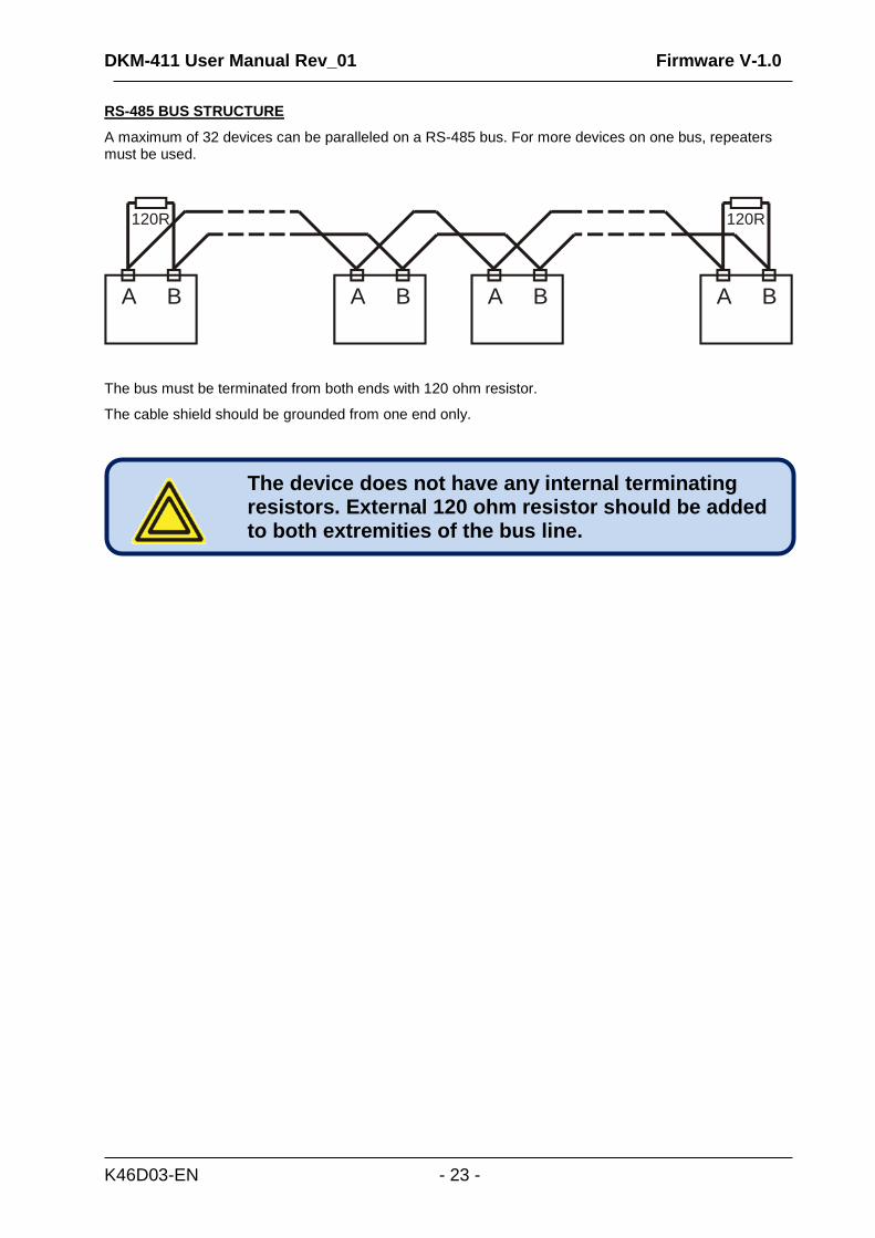
RS-485 BUS STRUCTURE
A maximum of 32 devices can be paralleled on a RS-485 bus. For more devices on one bus, repeaters must be used.
A B A B A BA B
120R 120R
The bus must be terminated from both ends with 120 ohm resistor.
The cable shield should be grounded from one end only.
The device does not have any internal terminating resistors. External 120 ohm resistor should be added to both extremities of the bus line.
DKM-411 User Manual Rev_01 Firmware V-1.0
K46D03-EN - 24 -
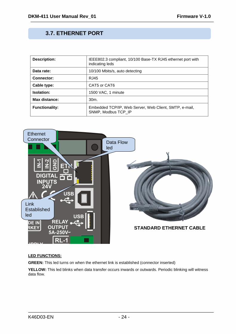
Description: IEEE802.3 compliant, 10/100 Base-TX RJ45 ethernet port with indicating leds
Data rate: 10/100 Mbits/s, auto detecting
Connector: RJ45
Cable type: CAT5 or CAT6
Isolation: 1500 VAC, 1 minute
Max distance: 30m.
Functionality: Embedded TCP/IP, Web Server, Web Client, SMTP, e-mail, SNMP, Modbus TCP_IP
STANDARD ETHERNET CABLE
LED FUNCTIONS:
GREEN: This led turns on when the ethernet link is established (connector inserted)
YELLOW: This led blinks when data transfer occurs inwards or outwards. Periodic blinking will witness data flow.
3.7. ETHERNET PORT
Ethernet Connector
Link Established led
Data Flow led
DKM-411 User Manual Rev_01 Firmware V-1.0
K46D03-EN - 25 -
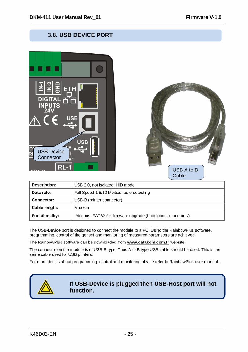
Description: USB 2.0, not isolated, HID mode
Data rate: Full Speed 1.5/12 Mbits/s, auto detecting
Connector: USB-B (printer connector)
Cable length: Max 6m
Functionality: Modbus, FAT32 for firmware upgrade (boot loader mode only)
The USB-Device port is designed to connect the module to a PC. Using the RainbowPlus software, programming, control of the genset and monitoring of measured parameters are achieved.
The RainbowPlus software can be downloaded from www.datakom.com.tr website.
The connector on the module is of USB-B type. Thus A to B type USB cable should be used. This is the same cable used for USB printers.
For more details about programming, control and monitoring please refer to RainbowPlus user manual.
If USB-Device is plugged then USB-Host port will not function.
3.8. USB DEVICE PORT
USB Device Connector
USB A to B Cable
DKM-411 User Manual Rev_01 Firmware V-1.0
K46D03-EN - 26 -
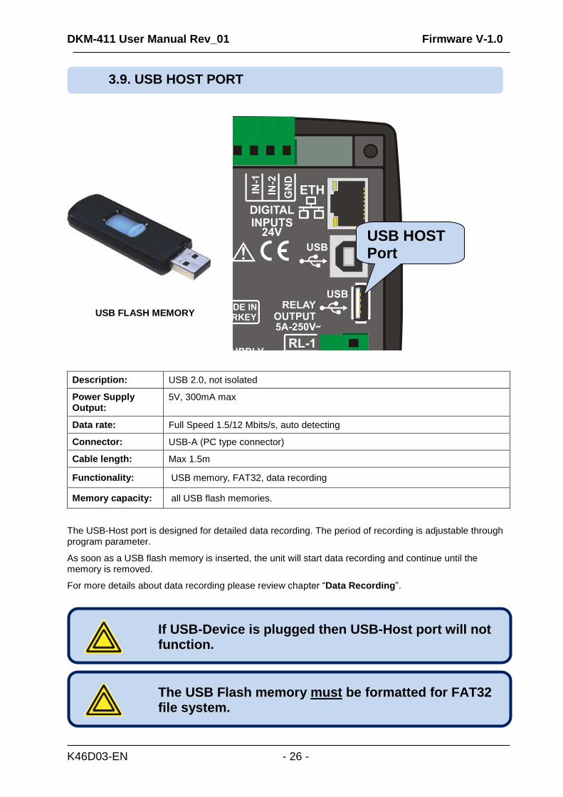
USB FLASH MEMORY
Description: USB 2.0, not isolated
Power Supply Output:
5V, 300mA max
Data rate: Full Speed 1.5/12 Mbits/s, auto detecting
Connector: USB-A (PC type connector)
Cable length: Max 1.5m
Functionality: USB memory, FAT32, data recording
Memory capacity: all USB flash memories.
The USB-Host port is designed for detailed data recording. The period of recording is adjustable through program parameter.
As soon as a USB flash memory is inserted, the unit will start data recording and continue until the memory is removed.
For more details about data recording please review chapter “Data Recording”.
The USB Flash memory must be formatted for FAT32 file system.
If USB-Device is plugged then USB-Host port will not function.
3.9. USB HOST PORT
USB HOST Port
DKM-411 User Manual Rev_01 Firmware V-1.0
K46D03-EN - 27 -
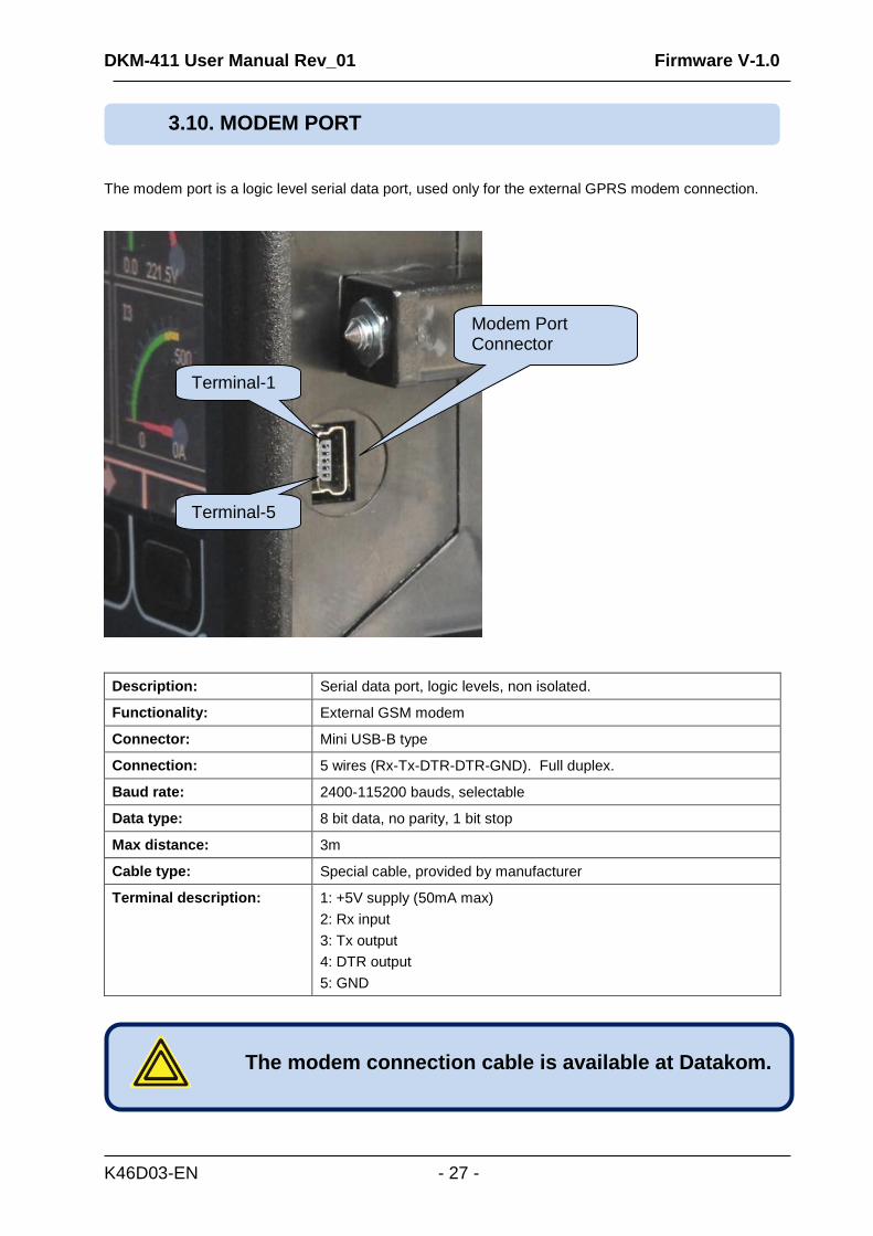
The modem port is a logic level serial data port, used only for the external GPRS modem connection.
Description: Serial data port, logic levels, non isolated.
Functionality: External GSM modem
Connector: Mini USB-B type
Connection: 5 wires (Rx-Tx-DTR-DTR-GND). Full duplex.
Baud rate: 2400-115200 bauds, selectable
Data type: 8 bit data, no parity, 1 bit stop
Max distance: 3m
Cable type: Special cable, provided by manufacturer
Terminal description: 1: +5V supply (50mA max)
2: Rx input
3: Tx output
4: DTR output
5: GND
The modem connection cable is available at Datakom.
3.10. MODEM PORT
Modem Port Connector
Terminal-1
Terminal-5
DKM-411 User Manual Rev_01 Firmware V-1.0
K46D03-EN - 28 -
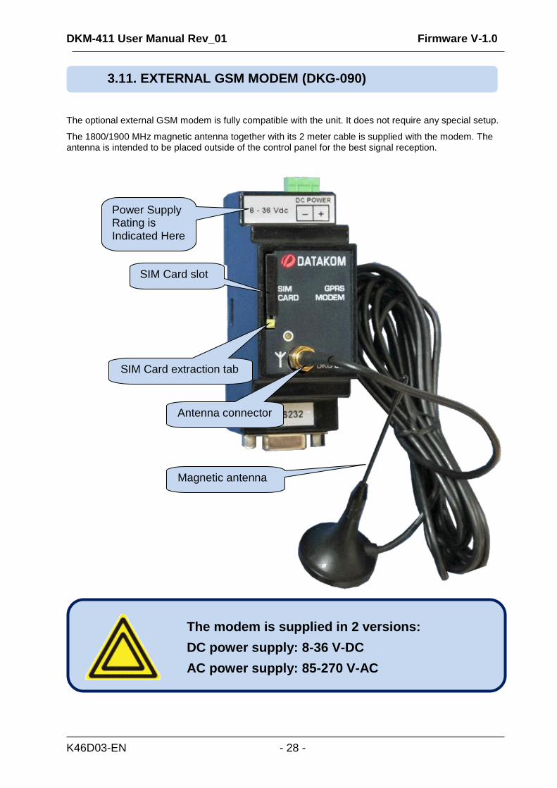
The optional external GSM modem is fully compatible with the unit. It does not require any special setup.
The 1800/1900 MHz magnetic antenna together with its 2 meter cable is supplied with the modem. The antenna is intended to be placed outside of the control panel for the best signal reception.
The modem is supplied in 2 versions:
DC power supply: 8-36 V-DC
AC power supply: 85-270 V-AC
3.11. EXTERNAL GSM MODEM (DKG-090)
SIM Card slot
SIM Card extraction tab
Antenna connector
Magnetic antenna
Power Supply Rating is Indicated Here
DKM-411 User Manual Rev_01 Firmware V-1.0
K46D03-EN - 29 -
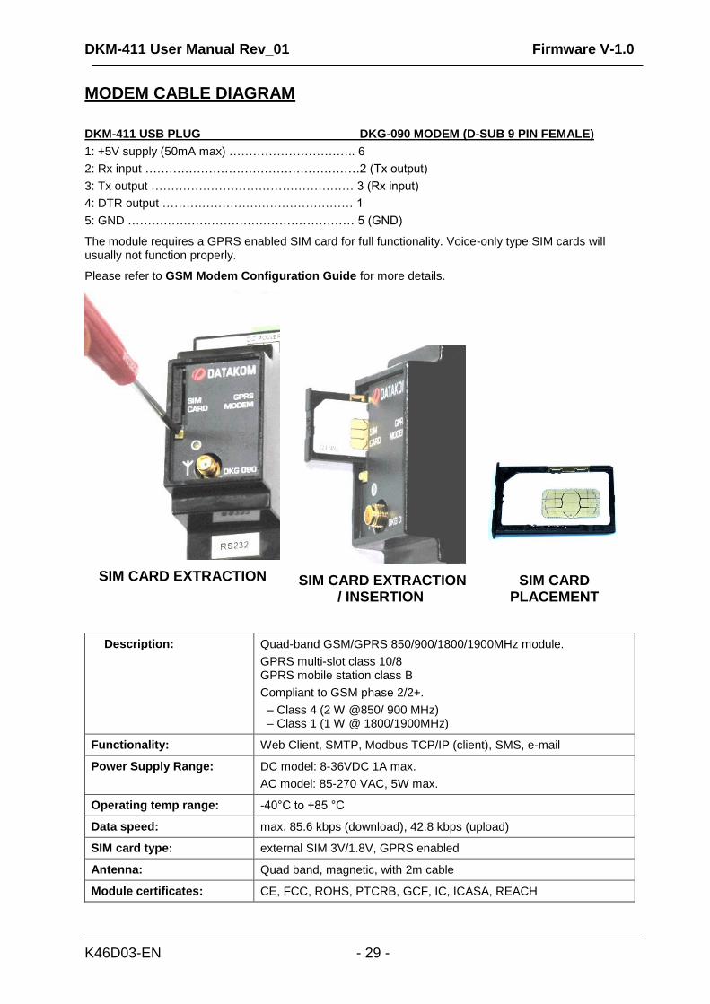
MODEM CABLE DIAGRAM
DKM-411 USB PLUG DKG-090 MODEM (D-SUB 9 PIN FEMALE)
1: +5V supply (50mA max) ………………………….. 6
2: Rx input ………………………………………………2 (Tx output)
3: Tx output …………………………………………… 3 (Rx input)
4: DTR output ………………………………………… 1
5: GND ………………………………………………… 5 (GND)
The module requires a GPRS enabled SIM card for full functionality. Voice-only type SIM cards will usually not function properly.
Please refer to GSM Modem Configuration Guide for more details.
SIM CARD EXTRACTION
SIM CARD EXTRACTION / INSERTION
SIM CARD PLACEMENT
Description: Quad-band GSM/GPRS 850/900/1800/1900MHz module.
GPRS multi-slot class 10/8 GPRS mobile station class B
Compliant to GSM phase 2/2+.
– Class 4 (2 W @850/ 900 MHz) – Class 1 (1 W @ 1800/1900MHz)
Functionality: Web Client, SMTP, Modbus TCP/IP (client), SMS, e-mail
Power Supply Range: DC model: 8-36VDC 1A max.
AC model: 85-270 VAC, 5W max.
Operating temp range: -40°C to +85 °C
Data speed: max. 85.6 kbps (download), 42.8 kbps (upload)
SIM card type: external SIM 3V/1.8V, GPRS enabled
Antenna: Quad band, magnetic, with 2m cable
Module certificates: CE, FCC, ROHS, PTCRB, GCF, IC, ICASA, REACH
DKM-411 User Manual Rev_01 Firmware V-1.0
K46D03-EN - 30 -
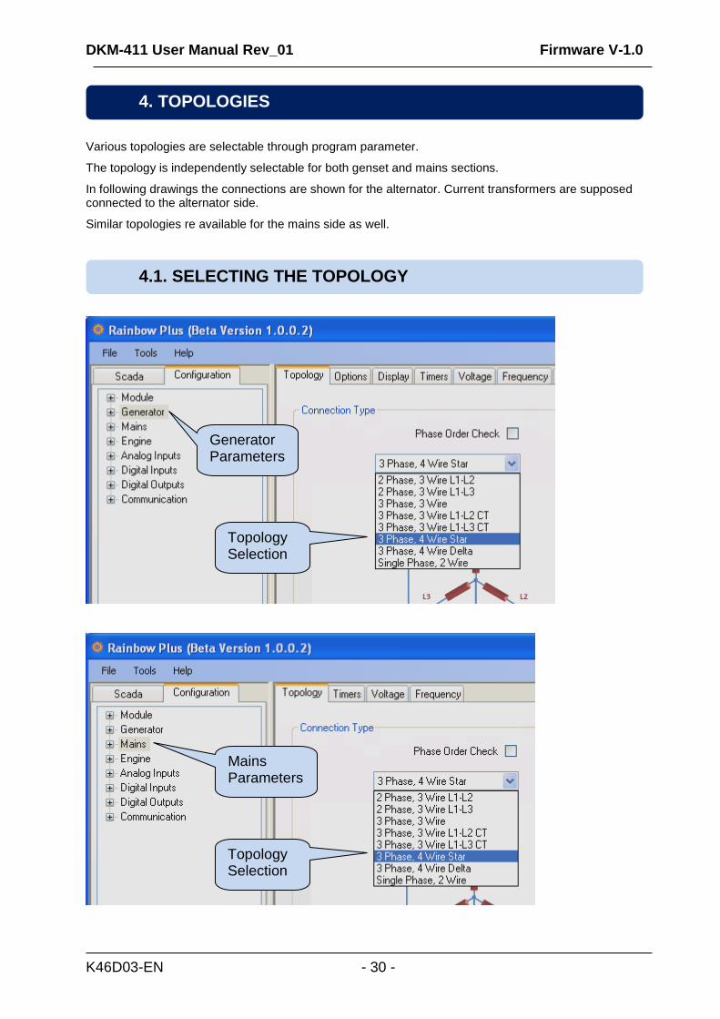
Various topologies are selectable through program parameter.
The topology is independently selectable for both genset and mains sections.
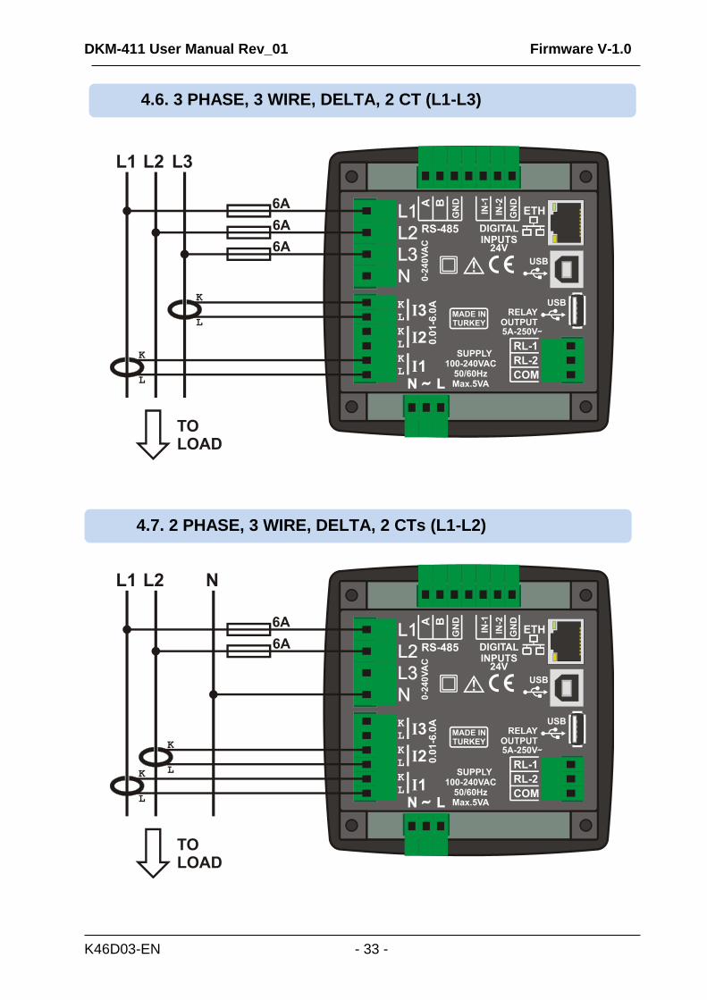
In following drawings the connections are shown for the alternator. Current transformers are supposed connected to the alternator side.
Similar topologies re available for the mains side as well.
4.1. SELECTING THE TOPOLOGY
4. TOPOLOGIES
Generator Parameterss
Topology Selection
Topology Selection
Mains Parameterss
DKM-411 User Manual Rev_01 Firmware V-1.0
K46D03-EN - 31 -
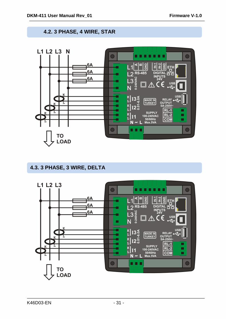
4.3. 3 PHASE, 3 WIRE, DELTA
4.2. 3 PHASE, 4 WIRE, STAR
DKM-411 User Manual Rev_01 Firmware V-1.0
K46D03-EN - 32 -
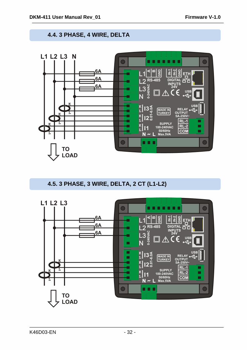
4.4. 3 PHASE, 4 WIRE, DELTA
4.5. 3 PHASE, 3 WIRE, DELTA, 2 CT (L1-L2)
DKM-411 User Manual Rev_01 Firmware V-1.0
K46D03-EN - 33 -
4.7. 2 PHASE, 3 WIRE, DELTA, 2 CTs (L1-L2)
4.6. 3 PHASE, 3 WIRE, DELTA, 2 CT (L1-L3)
DKM-411 User Manual Rev_01 Firmware V-1.0
K46D03-EN - 34 -
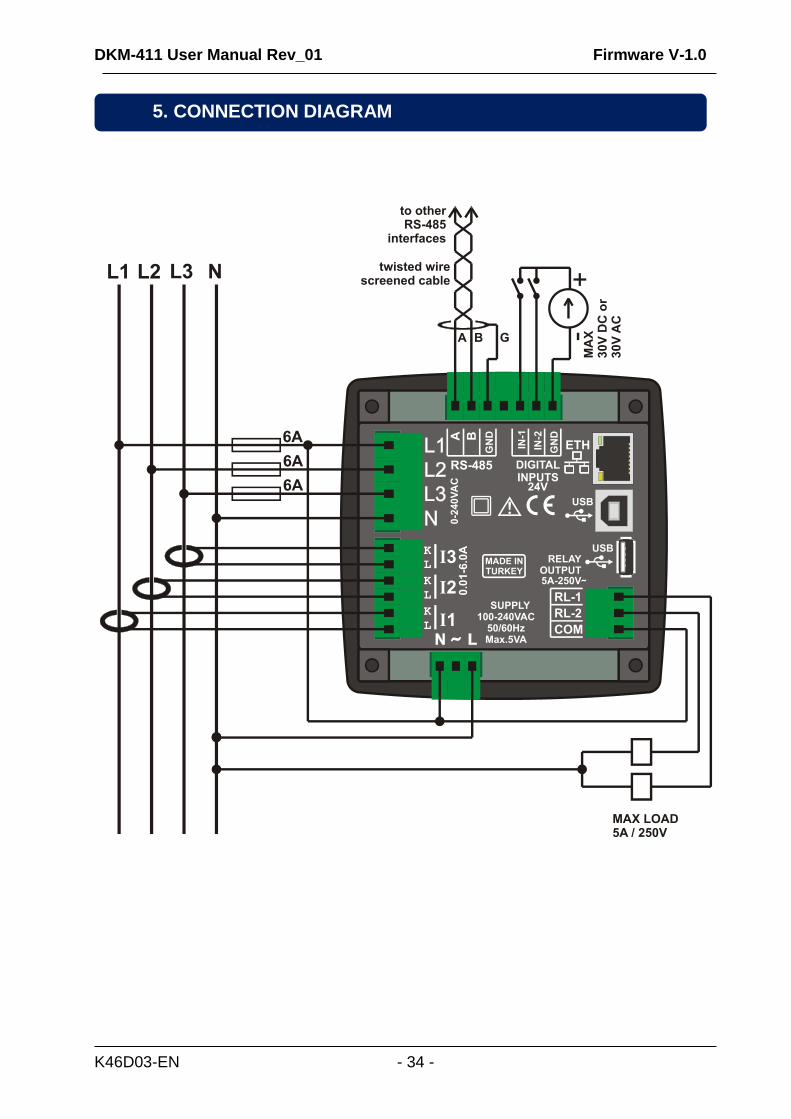
5. CONNECTION DIAGRAM
DKM-411 User Manual Rev_01 Firmware V-1.0
K46D03-EN - 35 -
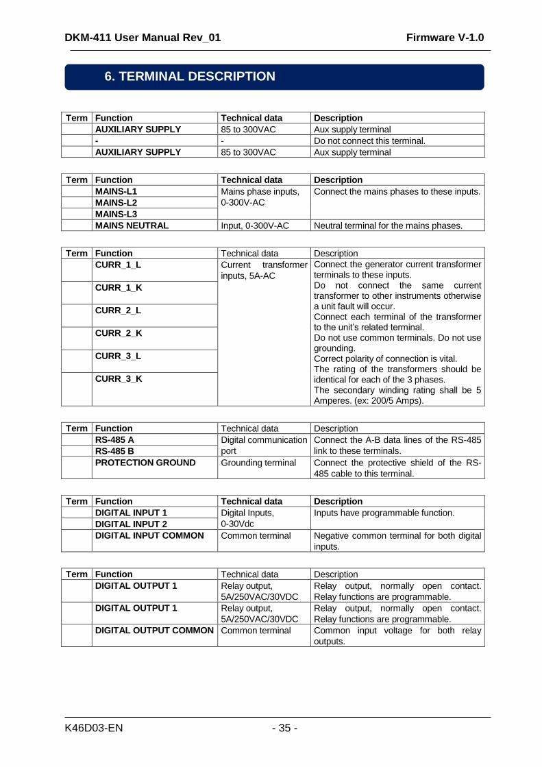
Term Function Technical data Description
AUXILIARY SUPPLY 85 to 300VAC Aux supply terminal
- - Do not connect this terminal.
AUXILIARY SUPPLY 85 to 300VAC Aux supply terminal
Term Function Technical data Description
MAINS-L1 Mains phase inputs,
0-300V-AC
Connect the mains phases to these inputs.
MAINS-L2
MAINS-L3
MAINS NEUTRAL Input, 0-300V-AC Neutral terminal for the mains phases.
Term Function Technical data Description
CURR_1_L Current transformer
inputs, 5A-AC
Connect the generator current transformer terminals to these inputs. Do not connect the same current transformer to other instruments otherwise a unit fault will occur. Connect each terminal of the transformer to the unit’s related terminal. Do not use common terminals. Do not use grounding. Correct polarity of connection is vital. The rating of the transformers should be identical for each of the 3 phases. The secondary winding rating shall be 5 Amperes. (ex: 200/5 Amps).
CURR_1_K
CURR_2_L
CURR_2_K
CURR_3_L
CURR_3_K
Term Function Technical data Description
RS-485 A Digital communication
port
Connect the A-B data lines of the RS-485
link to these terminals. RS-485 B
PROTECTION GROUND Grounding terminal Connect the protective shield of the RS-
485 cable to this terminal.
Term Function Technical data Description
DIGITAL INPUT 1 Digital Inputs,
0-30Vdc
Inputs have programmable function.
DIGITAL INPUT 2
DIGITAL INPUT COMMON Common terminal Negative common terminal for both digital
inputs.
Term Function Technical data Description
DIGITAL OUTPUT 1 Relay output,
5A/250VAC/30VDC
Relay output, normally open contact.
Relay functions are programmable.
DIGITAL OUTPUT 1 Relay output,
5A/250VAC/30VDC
Relay output, normally open contact.
Relay functions are programmable.
DIGITAL OUTPUT COMMON Common terminal Common input voltage for both relay
outputs.
6. TERMINAL DESCRIPTION
DKM-411 User Manual Rev_01 Firmware V-1.0
K46D03-EN - 36 -
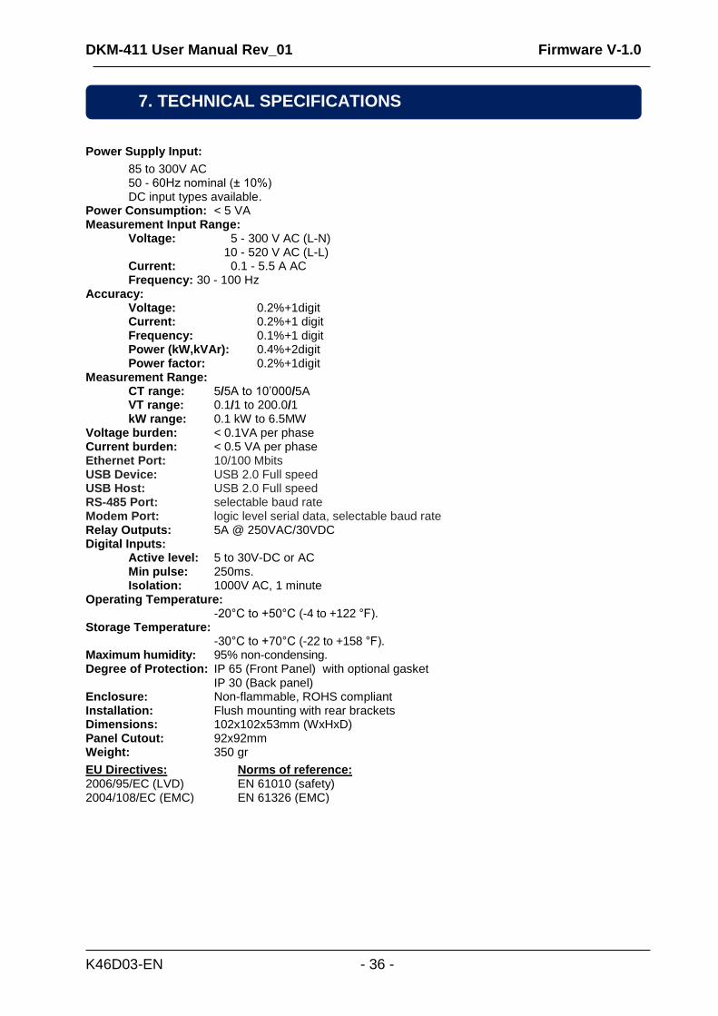
Power Supply Input:
85 to 300V AC 50 - 60Hz nominal (± 10%) DC input types available. Power Consumption: < 5 VA Measurement Input Range:
Voltage: 5 - 300 V AC (L-N) 10 - 520 V AC (L-L) Current: 0.1 - 5.5 A AC Frequency: 30 - 100 Hz
Accuracy: Voltage: 0.2%+1digit Current: 0.2%+1 digit Frequency: 0.1%+1 digit Power (kW,kVAr): 0.4%+2digit Power factor: 0.2%+1digit Measurement Range: CT range: 5/5A to 10’000/5A
VT range: 0.1/1 to 200.0/1 kW range: 0.1 kW to 6.5MW
Voltage burden: < 0.1VA per phase Current burden: < 0.5 VA per phase Ethernet Port: 10/100 Mbits USB Device: USB 2.0 Full speed USB Host: USB 2.0 Full speed RS-485 Port: selectable baud rate Modem Port: logic level serial data, selectable baud rate Relay Outputs: 5A @ 250VAC/30VDC Digital Inputs: Active level: 5 to 30V-DC or AC Min pulse: 250ms. Isolation: 1000V AC, 1 minute Operating Temperature: -20°C to +50°C (-4 to +122 °F). Storage Temperature: -30°C to +70°C (-22 to +158 °F). Maximum humidity: 95% non-condensing. Degree of Protection: IP 65 (Front Panel) with optional gasket IP 30 (Back panel) Enclosure: Non-flammable, ROHS compliant Installation: Flush mounting with rear brackets Dimensions: 102x102x53mm (WxHxD) Panel Cutout: 92x92mm Weight: 350 gr
EU Directives: 2006/95/EC (LVD) 2004/108/EC (EMC)
Norms of reference: EN 61010 (safety) EN 61326 (EMC)
7. TECHNICAL SPECIFICATIONS
DKM-411 User Manual Rev_01 Firmware V-1.0
K46D03-EN - 37 -
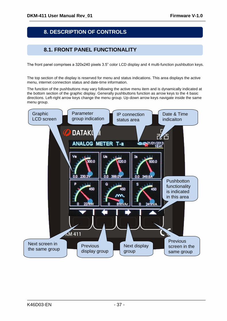
The front panel comprises a 320x240 pixels 3.5” color LCD display and 4 multi-function pushbutton keys.
The top section of the display is reserved for menu and status indications. This area displays the active menu, internet connection status and date-time information.
The function of the pushbuttons may vary following the active menu item and is dynamically indicated at the bottom section of the graphic display. Generally pushbuttons function as arrow keys to the 4 basic directions. Left-right arrow keys change the menu group. Up-down arrow keys navigate inside the same menu group.
8.1. FRONT PANEL FUNCTIONALITY
8. DESCRIPTION OF CONTROLS
Graphic LCD screen
Next screen in the same group
Previous display group
Next display group
Previous screen in the same group
IP connection status area
Parameter group indication
Date & Time indicaiton
Pushbotton functionality is indicated in this area
DKM-411 User Manual Rev_01 Firmware V-1.0
K46D03-EN - 38 -
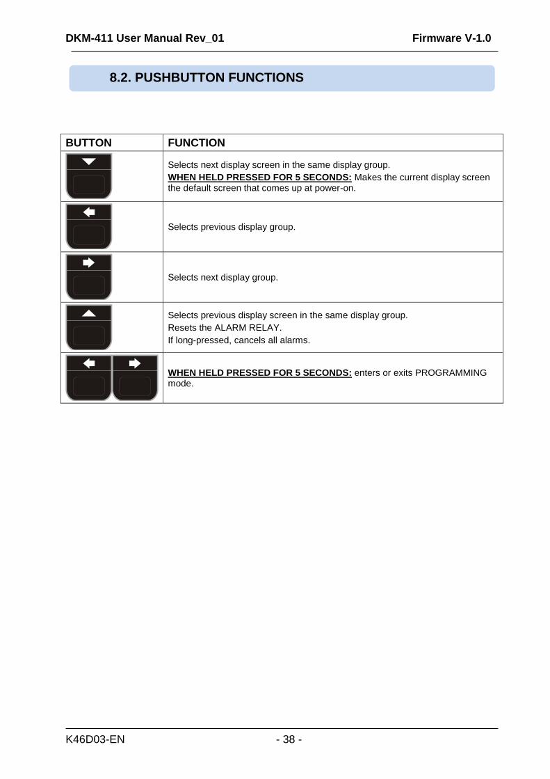
BUTTON FUNCTION
Selects next display screen in the same display group.
WHEN HELD PRESSED FOR 5 SECONDS: Makes the current display screen the default screen that comes up at power-on.
Selects previous display group.
Selects next display group.
Selects previous display screen in the same display group.
Resets the ALARM RELAY.
If long-pressed, cancels all alarms.
WHEN HELD PRESSED FOR 5 SECONDS: enters or exits PROGRAMMING mode.
8.2. PUSHBUTTON FUNCTIONS
DKM-411 User Manual Rev_01 Firmware V-1.0
K46D03-EN - 39 -
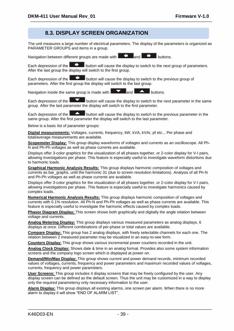
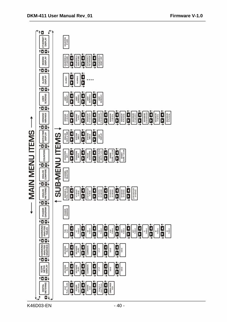
The unit measures a large number of electrical parameters. The display of the parameters is organized as PARAMETER GROUPS and items in a group.
Navigation between different groups are made with and buttons.
Each depression of the button will cause the display to switch to the next group of parameters. After the last group the display will switch to the first group.
Each depression of the button will cause the display to switch to the previous group of parameters. After the first group the display will switch to the last group.
Navigation inside the same group is made with and buttons.
Each depression of the button will cause the display to switch to the next parameter in the same group. After the last parameter the display will switch to the first parameter.
Each depression of the button will cause the display to switch to the previous parameter in the same group. After the first parameter the display will switch to the last parameter.
Below is a basic list of parameter groups:
Digital measurements: Voltages, currents, frequency, kW, kVA, kVAr, pf etc... Per phase and total/average measurements are available.
Scopemeter Display: This group display waveforms of voltages and currents as an oscilloscope. All Ph-N and Ph-Ph voltages as well as phase currents are available.
Displays offer 3-color graphics for the visualization of all phases together, or 2-color display for V-I pairs, allowing investigations per phase. This feature is especially useful to investigate waveform distortions due to harmonic loads.
Graphical Harmonic Analysis Results: This group displays harmonic composition of voltages and currents as bar_graphs, until the harmonic 31 (due to screen resolution limitations). Analysis of all Ph-N and Ph-Ph voltages as well as phase currents are available.
Displays offer 3-color graphics for the visualization of all phases together, or 2-color display for V-I pairs, allowing investigations per phase. This feature is especially useful to investigate harmonics caused by complex loads.
Numerical Harmonic Analysis Results: This group displays harmonic composition of voltages and currents with 0.1% resolution. All Ph-N and Ph-Ph voltages as well as phase currents are available. This feature is especially useful to investigate the harmonic effects caused by complex loads.
Phasor Diagram Display: This screen shows both graphically and digitally the angle relation between voltage and currents.
Analog Metering Display: This group displays various measured parameters as analog displays, 6 displays at once. Different combinations of per-phase or total values are available.
Compare Display: This group has 2 analog displays, with freely selectable channels for each one. The relation between 2 measured parameter may be visualized in an easy-to-see form.
Counters Display: This group shows various incremental power counters recorded in the unit.
Analog Clock Display: Shows date & time in an analog format. Provides also some system information screens and the company logo screen which is displayed at power-on.
Demand/Min/Max Display: This group shows current and power demand records, minimum recorded values of voltages, currents, frequency and power parameters and maximum recorded values of voltages, currents, frequency and power parameters.
User Screens: This group includes 4 display screens that may be freely configured by the user. Any display screen can be defined as the default screen. Thus the unit may be customized in a way to display only the required parametersy only necessary information to the user.
Alarm Display: This group displays all existing alarms, one screen per alarm. When there is no more alarm to display it will show “END OF ALARM LIST”.
8.3. DISPLAY SCREEN ORGANIZATION
DKM-411 User Manual Rev_01 Firmware V-1.0
K46D03-EN - 40 -
DKM-411 User Manual Rev_01 Firmware V-1.0
K46D03-EN - 41 -
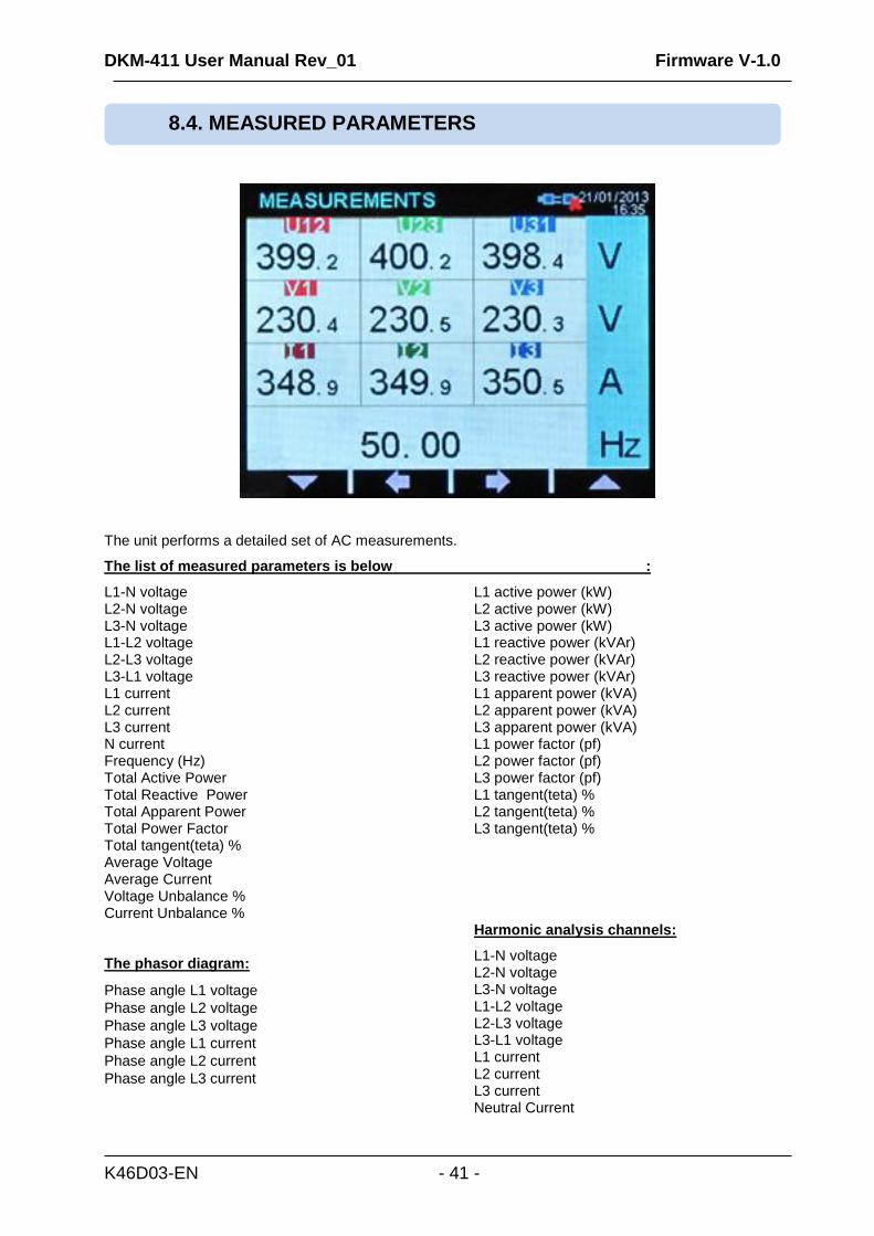
The unit performs a detailed set of AC measurements.
The list of measured parameters is below :
L1-N voltage L2-N voltage L3-N voltage L1-L2 voltage L2-L3 voltage L3-L1 voltage L1 current L2 current L3 current N current Frequency (Hz) Total Active Power Total Reactive Power Total Apparent Power Total Power Factor Total tangent(teta) % Average Voltage Average Current Voltage Unbalance % Current Unbalance % The phasor diagram:
Phase angle L1 voltage
Phase angle L2 voltage
Phase angle L3 voltage
Phase angle L1 current
Phase angle L2 current
Phase angle L3 current
L1 active power (kW) L2 active power (kW) L3 active power (kW) L1 reactive power (kVAr) L2 reactive power (kVAr) L3 reactive power (kVAr) L1 apparent power (kVA) L2 apparent power (kVA) L3 apparent power (kVA) L1 power factor (pf) L2 power factor (pf) L3 power factor (pf) L1 tangent(teta) % L2 tangent(teta) % L3 tangent(teta) % Harmonic analysis channels:
L1-N voltage L2-N voltage L3-N voltage L1-L2 voltage L2-L3 voltage L3-L1 voltage L1 current L2 current L3 current Neutral Current
8.4. MEASURED PARAMETERS
DKM-411 User Manual Rev_01 Firmware V-1.0
K46D03-EN - 42 -
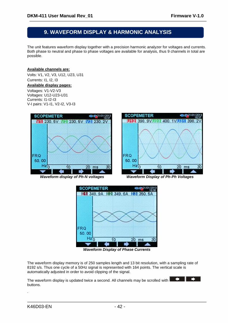
The unit features waveform display together with a precision harmonic analyzer for voltages and currents. Both phase to neutral and phase to phase voltages are available for analysis, thus 9 channels in total are possible.
Available channels are:
Volts: V1, V2, V3, U12, U23, U31
Currents: I1, I2, I3
Available display pages:
Voltages: V1-V2-V3 Voltages: U12-U23-U31 Currents: I1-I2-I3 V-I pairs: V1-I1, V2-I2, V3-I3
Waveform display of Ph-N voltages Waveform Display of Ph-Ph Voltages
Waveform Display of Phase Currents
The waveform display memory is of 250 samples length and 13 bit resolution, with a sampling rate of 8192 s/s. Thus one cycle of a 50Hz signal is represented with 164 points. The vertical scale is automatically adjusted in order to avoid clipping of the signal.
The waveform display is updated twice a second. All channels may be scrolled with buttons.
.
9. WAVEFORM DISPLAY & HARMONIC ANALYSIS
DKM-411 User Manual Rev_01 Firmware V-1.0
K46D03-EN - 43 -
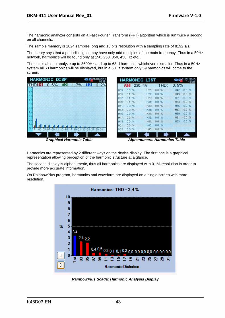
The harmonic analyzer consists on a Fast Fourier Transform (FFT) algorithm which is run twice a second on all channels.
The sample memory is 1024 samples long and 13 bits resolution with a sampling rate of 8192 s/s.
The theory says that a periodic signal may have only odd multiples of the main frequency. Thus in a 50Hz network, harmonics will be found only at 150, 250, 350, 450 Hz etc...
The unit is able to analyze up to 3600Hz and up to 63rd harmonic, whichever is smaller. Thus in a 50Hz system all 63 harmonics will be displayed, but in a 60Hz system only 59 harmonics will come to the screen.
Graphical Harmonic Table Alphanumeric Harmonics Table
Harmonics are represented by 2 different ways on the device display. The first one is a graphical representation allowing perception of the harmonic structure at a glance.
The second display is alphanumeric, thus all harmonics are displayed with 0.1% resolution in order to provide more accurate information.
On RainbowPlus program, harmonics and waveform are displayed on a single screen with more resolution.
RainbowPlus Scada: Harmonic Analysis Display
DKM-411 User Manual Rev_01 Firmware V-1.0
K46D03-EN - 44 -
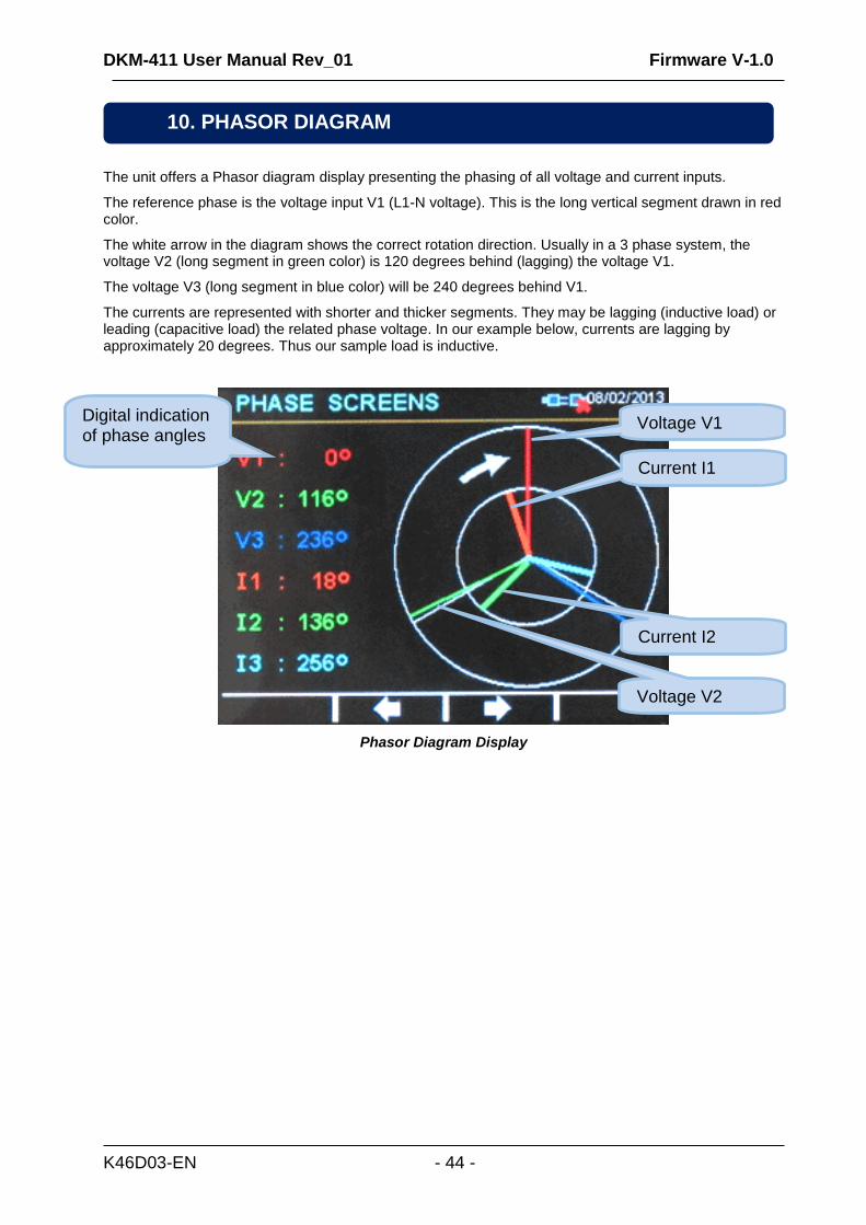
The unit offers a Phasor diagram display presenting the phasing of all voltage and current inputs.
The reference phase is the voltage input V1 (L1-N voltage). This is the long vertical segment drawn in red color.
The white arrow in the diagram shows the correct rotation direction. Usually in a 3 phase system, the voltage V2 (long segment in green color) is 120 degrees behind (lagging) the voltage V1.
The voltage V3 (long segment in blue color) will be 240 degrees behind V1.
The currents are represented with shorter and thicker segments. They may be lagging (inductive load) or leading (capacitive load) the related phase voltage. In our example below, currents are lagging by approximately 20 degrees. Thus our sample load is inductive.
Phasor Diagram Display
10. PHASOR DIAGRAM
Voltage V1 Digital indication of phase angles
Current I1
Voltage V2
Current I2
DKM-411 User Manual Rev_01 Firmware V-1.0
K46D03-EN - 45 -
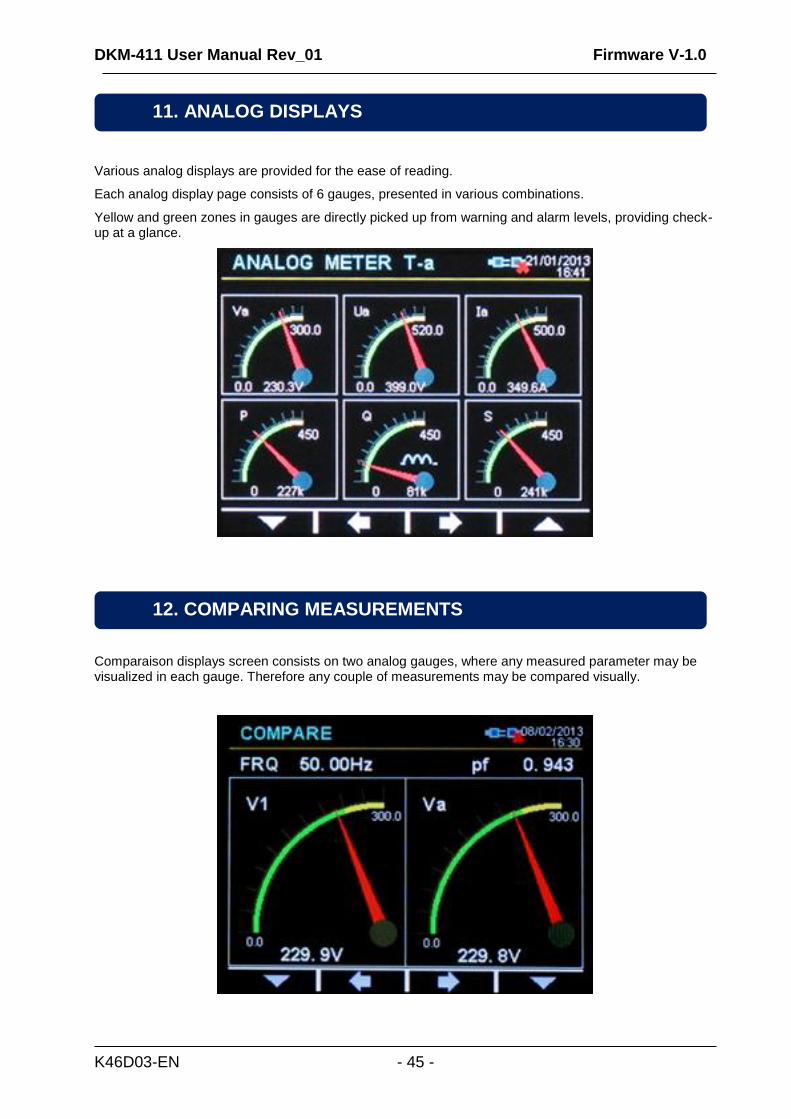
Various analog displays are provided for the ease of reading.
Each analog display page consists of 6 gauges, presented in various combinations.
Yellow and green zones in gauges are directly picked up from warning and alarm levels, providing check-up at a glance.
Comparaison displays screen consists on two analog gauges, where any measured parameter may be visualized in each gauge. Therefore any couple of measurements may be compared visually.
12. COMPARING MEASUREMENTS
11. ANALOG DISPLAYS
DKM-411 User Manual Rev_01 Firmware V-1.0
K46D03-EN - 46 -
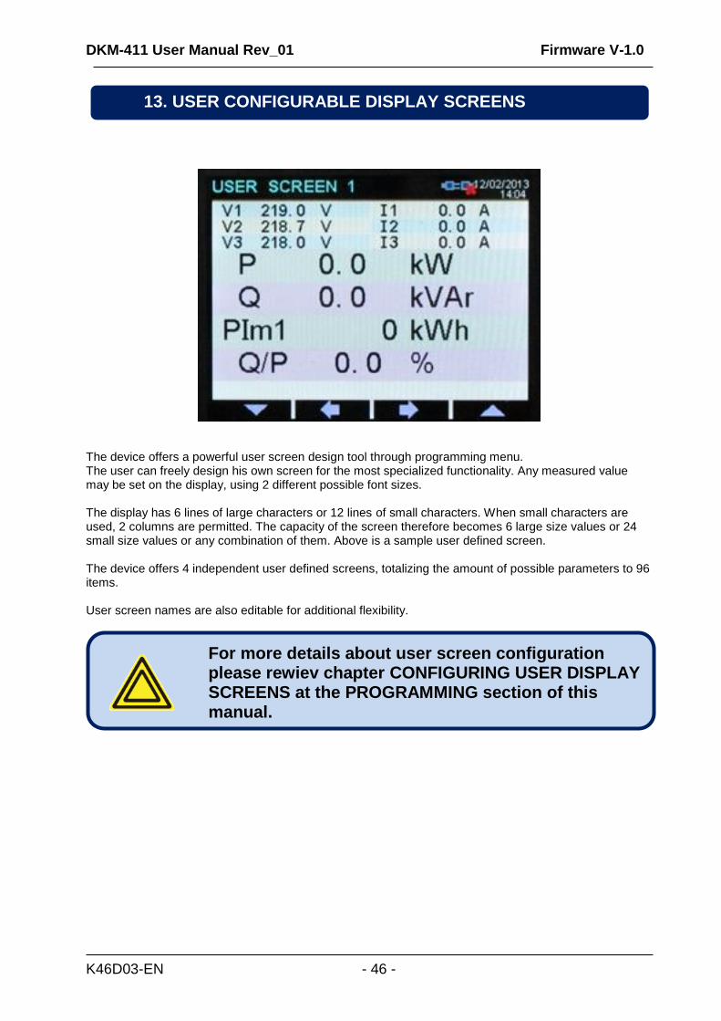
The device offers a powerful user screen design tool through programming menu. The user can freely design his own screen for the most specialized functionality. Any measured value may be set on the display, using 2 different possible font sizes. The display has 6 lines of large characters or 12 lines of small characters. When small characters are used, 2 columns are permitted. The capacity of the screen therefore becomes 6 large size values or 24 small size values or any combination of them. Above is a sample user defined screen. The device offers 4 independent user defined screens, totalizing the amount of possible parameters to 96 items. User screen names are also editable for additional flexibility.
For more details about user screen configuration please rewiev chapter CONFIGURING USER DISPLAY SCREENS at the PROGRAMMING section of this manual.
13. USER CONFIGURABLE DISPLAY SCREENS
DKM-411 User Manual Rev_01 Firmware V-1.0
K46D03-EN - 47 -
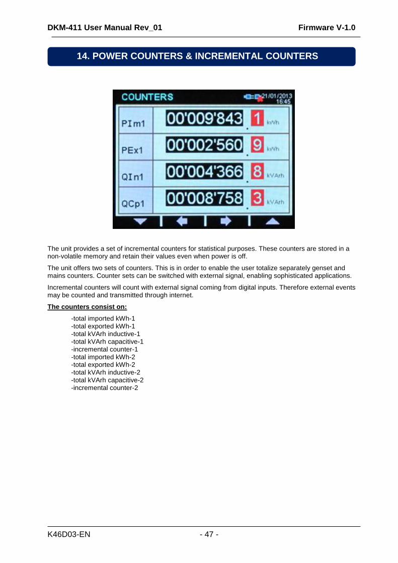
The unit provides a set of incremental counters for statistical purposes. These counters are stored in a non-volatile memory and retain their values even when power is off.
The unit offers two sets of counters. This is in order to enable the user totalize separately genset and mains counters. Counter sets can be switched with external signal, enabling sophisticated applications.
Incremental counters will count with external signal coming from digital inputs. Therefore external events may be counted and transmitted through internet.
The counters consist on:
-total imported kWh-1 -total exported kWh-1 -total kVArh inductive-1 -total kVArh capacitive-1 -incremental counter-1 -total imported kWh-2 -total exported kWh-2 -total kVArh inductive-2 -total kVArh capacitive-2 -incremental counter-2
14. POWER COUNTERS & INCREMENTAL COUNTERS
DKM-411 User Manual Rev_01 Firmware V-1.0
K46D03-EN - 48 -
Demand values are average values of measured parameters over a 15 minute period.
The unit starts a demand calculation period every 15 minutes (synchronized to the real time clock). The average values at the end of the period are compared with the demand registers, if higher, the new demand is stored into the register.
Demand registers are reset at the beginning of each month. Therefore demands are effective for the current month.
Demand registers are stored in a non-volatile memory and retain their values even when power is off.
Below demand registers are available:
-demand I1 -demand I2 -demand I3 -demand Ia (average current) -demand active power -demand reactive power.
Min-max values are based on instantaneous measurements. They have no averaging periods, therefore excessive values may be stored during short duration peak demands, like electric motor starts or inrush currents that flow at power-on.
During operation, the unit compares the instantaneous value with the storage registers, if higher, the new value is stored into the register.
Min-max registers are reset through programming mode. The related parameter is: COUNTER/MIN/MAX>Restart Min/Max
Min-max registers are stored in a non-volatile memory and retain their values even when power is off.
For stability purposes, the min-max detection starts 5 seconds after power turns on.
Below min-max registers are available :
-Min voltage L1-N -Min voltage L2-N -Min voltage L3-N -Min voltage L1-2 -Min voltage L2-3 -Min voltage L3-1 -Min frequency -Min current I1 -Min current I2 -Min current I3 -Min current Ia (average current) -Min import active power -Min export active power -Min inductive reactive power -Min capacitive reactive power
-Max voltage L1-N -Max voltage L2-N -Max voltage L3-N -Max voltage L1-2 -Max voltage L2-3 -Max voltage L3-1 -Max frequency -Max current I1 -Max current I2 -Max current I3 -Max current Ia (average current) -Max import active power -Max export active power -Max inductive reactive power -Max capacitive reactive power
16. MIN-MAX VALUES
15. DEMAND VALUES
DKM-411 User Manual Rev_01 Firmware V-1.0
K46D03-EN - 49 -
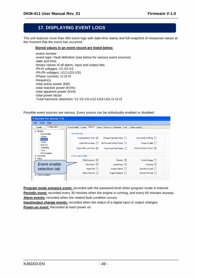
The unit features more than 400 event logs with date-time stamp and full snapshot of measured values at the moment that the event has occurred.
Stored values in an event record are listed below:
-event number -event type / fault definition (see below for various event sources) -date and time -binary values of all alarm, input and output bits. -Ph-N voltages: V1-V2-V3 -Ph-Ph voltages: U12-U23-U31 -Phase currents: I1-I2-I3 -frequency -total active power (kW) -total reactive power (kVAr) -total apparent power (kVA) -total power factor -Total harmonic distortion: V1-V2-V3-U12-U23-U31-I1-I2-I3
Possible event sources are various. Every source can be individually enabled or disabled:
Program mode entrance event: recorded with the password level when program mode is entered.
Periodic event: recorded every 30 minutes when the engine is running, and every 60 minutes anyway.
Alarm events: recorded when the related fault condition occurs.
Input/output change events: recorded when the status of a digital input or output changes.
Power-on event: Recorded at each power on.
17. DISPLAYING EVENT LOGS
Event enable selection tab
DKM-411 User Manual Rev_01 Firmware V-1.0
K46D03-EN - 50 -
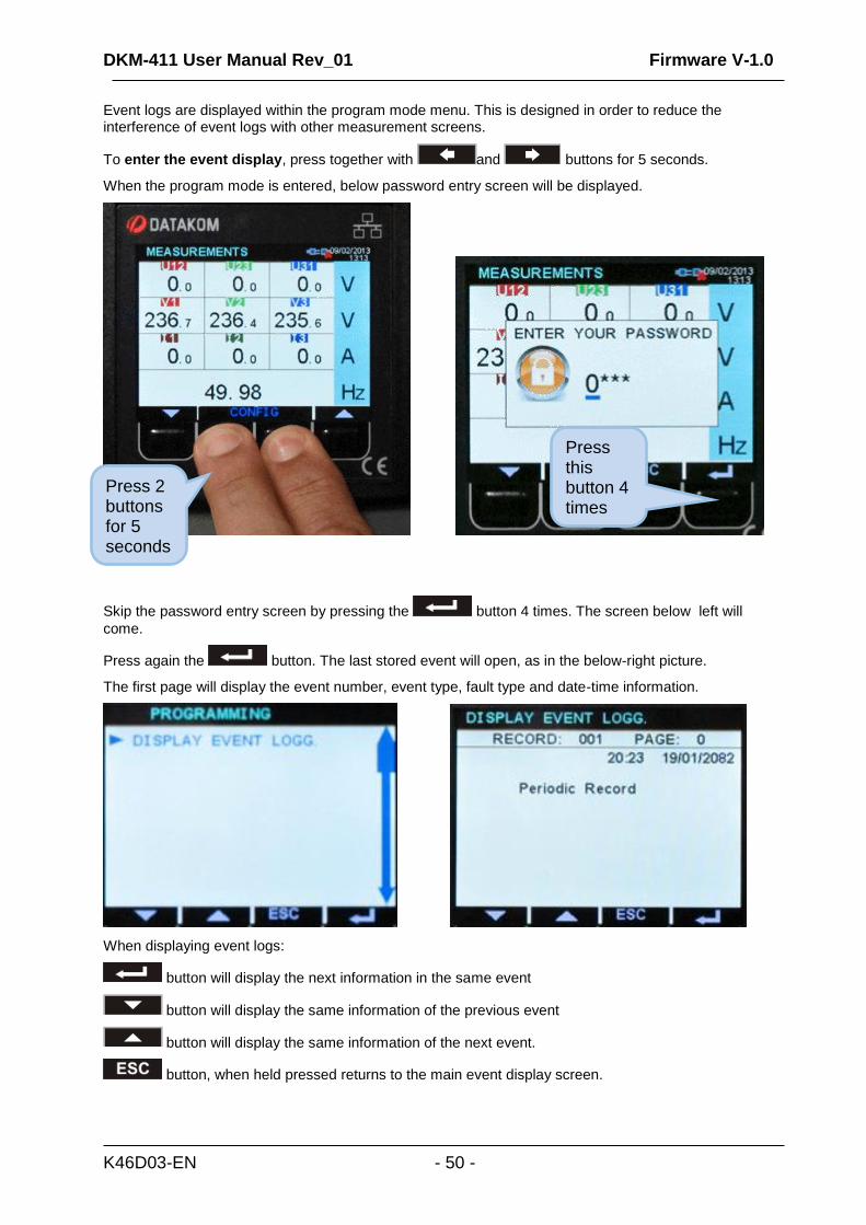
Event logs are displayed within the program mode menu. This is designed in order to reduce the interference of event logs with other measurement screens.
To enter the event display, press together with and buttons for 5 seconds.
When the program mode is entered, below password entry screen will be displayed.
Skip the password entry screen by pressing the button 4 times. The screen below left will
come.
Press again the button. The last stored event will open, as in the below-right picture.
The first page will display the event number, event type, fault type and date-time information.
When displaying event logs:
button will display the next information in the same event
button will display the same information of the previous event
button will display the same information of the next event.
button, when held pressed returns to the main event display screen.
Press 2 buttons for 5 seconds
Press this button 4 times
DKM-411 User Manual Rev_01 Firmware V-1.0
K46D03-EN - 51 -
The device is able to generate fault conditions on adjustable limits of measured parameters.
Fault cases are considered under two categories, namely alarm and warnings:
1- ALARMS: These are the most important fault conditions.
2- WARNINGS: Less severe fault conditions.
Occurring fault conditions will cause the related function to become active. These conditions are displayed in
the ALARM LIST screen. Conditions may also be assigned to relay outputs, activating external circuitry.
Alarms operate in a first occurring basis:
-If an alarm is present, following alarms and warnings will not be accepted,
-If a warning is present, following warnings will not be accepted.
Alarms may be of LATCHING type following programming.
For latching alarms, even if the alarm condition is removed, the alarms will stay on and disable the operation
of the genset.
Most of the alarms have programmable trip levels. See the programming chapter for adjustable alarm limits.
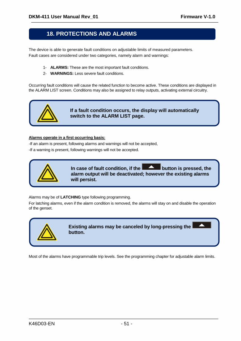
In case of fault condition, if the button is pressed, the alarm output will be deactivated; however the existing alarms will persist.
If a fault condition occurs, the display will automatically switch to the ALARM LIST page.
Existing alarms may be canceled by long-pressing the
button.
18. PROTECTIONS AND ALARMS
DKM-411 User Manual Rev_01 Firmware V-1.0
K46D03-EN - 52 -
The program mode is used to adjust timers, operational limits and the configuration of the unit.
Although a free PC program is provided for programming, every parameter may be modified through the front
panel, regardless of the operating mode.
When modified, program parameters are automatically recorded into a non-erasable memory and take effect
immediately.
The program mode will not affect the operation of the unit. Thus programs may be modified anytime.
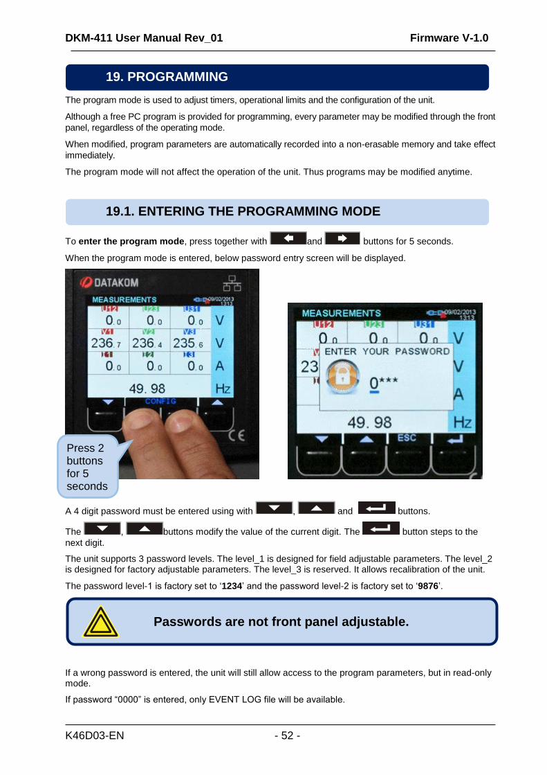
To enter the program mode, press together with and buttons for 5 seconds.
When the program mode is entered, below password entry screen will be displayed.
A 4 digit password must be entered using with , and buttons.
The , buttons modify the value of the current digit. The button steps to the
next digit.
The unit supports 3 password levels. The level_1 is designed for field adjustable parameters. The level_2 is designed for factory adjustable parameters. The level_3 is reserved. It allows recalibration of the unit.
The password level-1 is factory set to ‘1234’ and the password level-2 is factory set to ‘9876’.
If a wrong password is entered, the unit will still allow access to the program parameters, but in read-only mode.
If password “0000” is entered, only EVENT LOG file will be available.
Passwords are not front panel adjustable.
19.1. ENTERING THE PROGRAMMING MODE
19. PROGRAMMING
Press 2 buttons for 5 seconds
DKM-411 User Manual Rev_01 Firmware V-1.0
K46D03-EN - 53 -
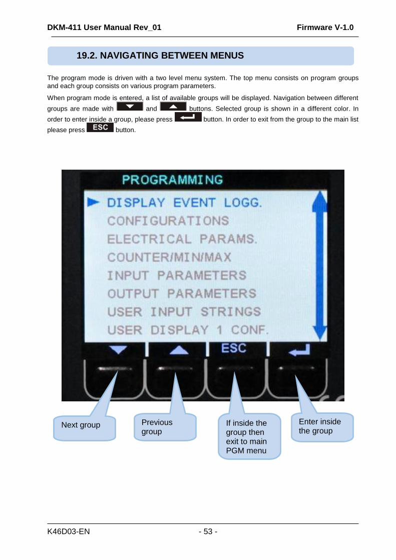
The program mode is driven with a two level menu system. The top menu consists on program groups
and each group consists on various program parameters.
When program mode is entered, a list of available groups will be displayed. Navigation between different
groups are made with and buttons. Selected group is shown in a different color. In
order to enter inside a group, please press button. In order to exit from the group to the main list
please press button.
19.2. NAVIGATING BETWEEN MENUS
Next group If inside the group then exit to main PGM menu
Previous group
Enter inside the group
DKM-411 User Manual Rev_01 Firmware V-1.0
K46D03-EN - 54 -
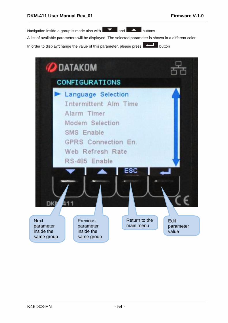
Navigation inside a group is made also with and buttons.
A list of available parameters will be displayed. The selected parameter is shown in a different color.
In order to display/change the value of this parameter, please press button
Next parameter inside the same group
Previous parameter inside the same group
Return to the main menu
Edit parameter value
DKM-411 User Manual Rev_01 Firmware V-1.0
K46D03-EN - 55 -
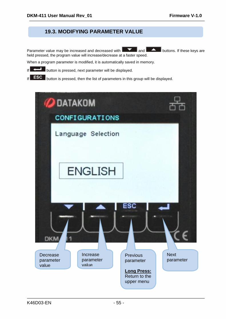
Parameter value may be increased and decreased with and buttons. If these keys are
held pressed, the program value will increase/decrease at a faster speed.
When a program parameter is modified, it is automatically saved in memory.
If button is pressed, next parameter will be displayed.
If button is pressed, then the list of parameters in this group will be displayed.
19.3. MODIFYING PARAMETER VALUE
Decrease parameter value
Increase parameter value
Previous parameter Long Press: Return to the upper menu
Next parameter
DKM-411 User Manual Rev_01 Firmware V-1.0
K46D03-EN - 56 -
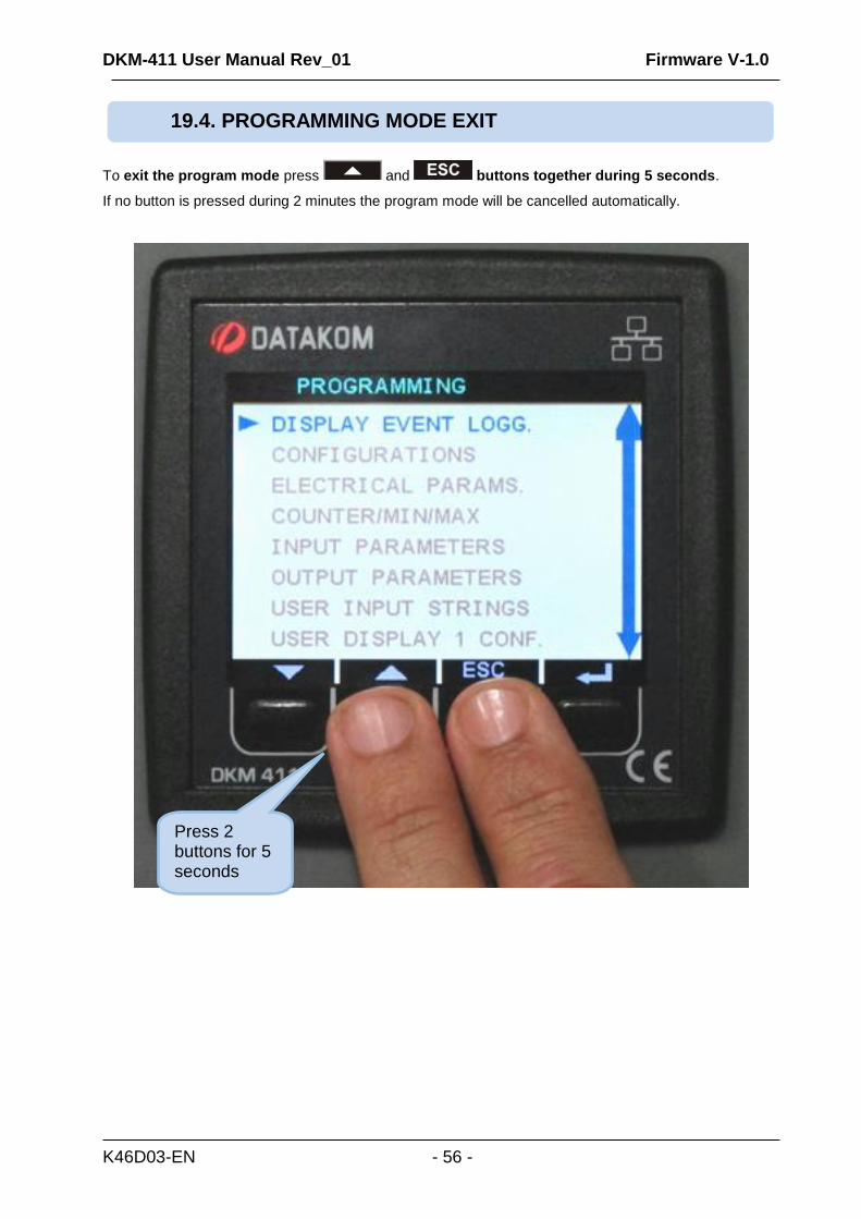
To exit the program mode press and buttons together during 5 seconds.
If no button is pressed during 2 minutes the program mode will be cancelled automatically.
19.4. PROGRAMMING MODE EXIT
Press 2 buttons for 5 seconds
DKM-411 User Manual Rev_01 Firmware V-1.0
K46D03-EN - 57 -
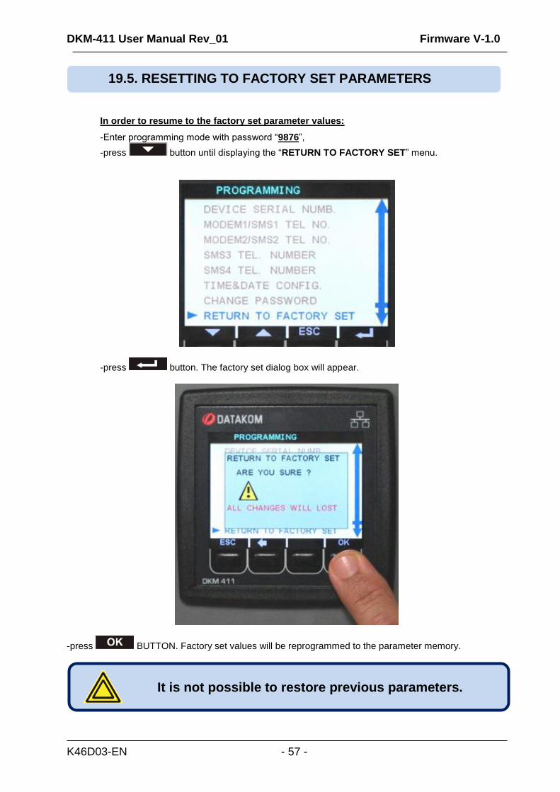
In order to resume to the factory set parameter values:
-Enter programming mode with password “9876”,
-press button until displaying the “RETURN TO FACTORY SET” menu.
-press button. The factory set dialog box will appear.
-press BUTTON. Factory set values will be reprogrammed to the parameter memory.
It is not possible to restore previous parameters.
19.5. RESETTING TO FACTORY SET PARAMETERS
DKM-411 User Manual Rev_01 Firmware V-1.0
K46D03-EN - 58 -
Parameter Definition Unit Min Max Factory Set
Description
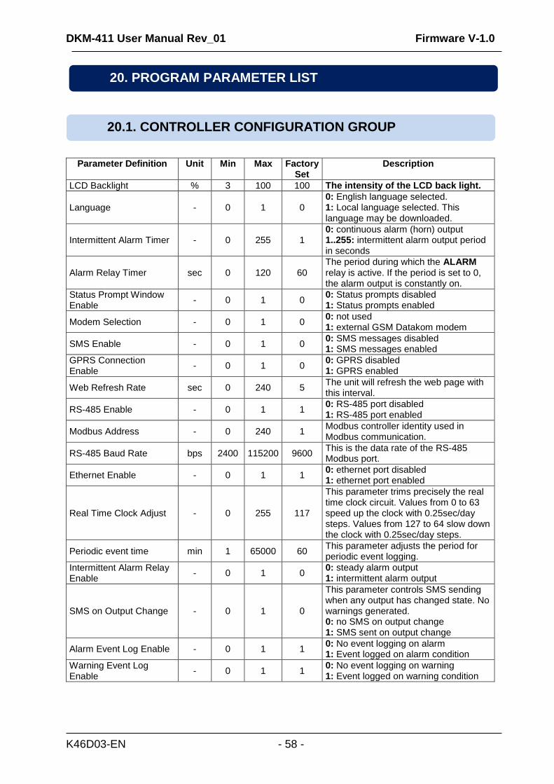
LCD Backlight % 3 100 100 The intensity of the LCD back light.
Language - 0 1 0 0: English language selected. 1: Local language selected. This language may be downloaded.
Intermittent Alarm Timer - 0 255 1 0: continuous alarm (horn) output 1..255: intermittent alarm output period in seconds
Alarm Relay Timer sec 0 120 60 The period during which the ALARM relay is active. If the period is set to 0, the alarm output is constantly on.
Status Prompt Window Enable
- 0 1 0 0: Status prompts disabled 1: Status prompts enabled
Modem Selection - 0 1 0 0: not used 1: external GSM Datakom modem
SMS Enable - 0 1 0 0: SMS messages disabled 1: SMS messages enabled
GPRS Connection Enable
- 0 1 0 0: GPRS disabled 1: GPRS enabled
Web Refresh Rate sec 0 240 5 The unit will refresh the web page with this interval.
RS-485 Enable - 0 1 1 0: RS-485 port disabled 1: RS-485 port enabled
Modbus Address - 0 240 1 Modbus controller identity used in Modbus communication.
RS-485 Baud Rate bps 2400 115200 9600 This is the data rate of the RS-485 Modbus port.
Ethernet Enable - 0 1 1 0: ethernet port disabled 1: ethernet port enabled
Real Time Clock Adjust - 0 255 117
This parameter trims precisely the real time clock circuit. Values from 0 to 63 speed up the clock with 0.25sec/day steps. Values from 127 to 64 slow down the clock with 0.25sec/day steps.
Periodic event time min 1 65000 60 This parameter adjusts the period for periodic event logging.
Intermittent Alarm Relay Enable
- 0 1 0 0: steady alarm output 1: intermittent alarm output
SMS on Output Change - 0 1 0
This parameter controls SMS sending when any output has changed state. No warnings generated. 0: no SMS on output change 1: SMS sent on output change
Alarm Event Log Enable - 0 1 1 0: No event logging on alarm 1: Event logged on alarm condition
Warning Event Log Enable
- 0 1 1 0: No event logging on warning 1: Event logged on warning condition
20. PROGRAM PARAMETER LIST
20.1. CONTROLLER CONFIGURATION GROUP
DKM-411 User Manual Rev_01 Firmware V-1.0
K46D03-EN - 59 -
Parameter Definition Unit Min Max Factory Set
Description
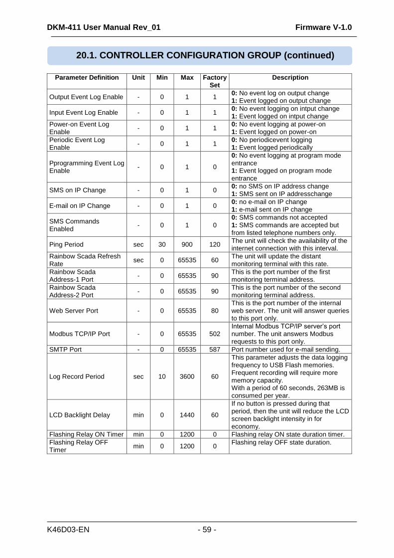
Output Event Log Enable - 0 1 1 0: No event log on output change 1: Event logged on output change
Input Event Log Enable - 0 1 1 0: No event logging on intput change 1: Event logged on intput change
Power-on Event Log Enable
- 0 1 1 0: No event logging at power-on 1: Event logged on power-on
Periodic Event Log Enable
- 0 1 1 0: No periodicevent logging 1: Event logged periodically
Pprogramming Event Log Enable
- 0 1 0
0: No event logging at program mode entrance 1: Event logged on program mode entrance
SMS on IP Change - 0 1 0 0: no SMS on IP address change 1: SMS sent on IP addresschange
E-mail on IP Change - 0 1 0 0: no e-mail on IP change 1: e-mail sent on IP change
SMS Commands Enabled
- 0 1 0 0: SMS commands not accepted 1: SMS commands are accepted but from listed telephone numbers only.
Ping Period sec 30 900 120 The unit will check the availability of the internet connection with this interval.
Rainbow Scada Refresh Rate
sec 0 65535 60 The unit will update the distant monitoring terminal with this rate.
Rainbow Scada Address-1 Port
- 0 65535 90 This is the port number of the first monitoring terminal address.
Rainbow Scada Address-2 Port
- 0 65535 90 This is the port number of the second monitoring terminal address.
Web Server Port - 0 65535 80 This is the port number of the internal web server. The unit will answer queries to this port only.
Modbus TCP/IP Port - 0 65535 502 Internal Modbus TCP/IP server’s port number. The unit answers Modbus requests to this port only.
SMTP Port - 0 65535 587 Port number used for e-mail sending.
Log Record Period sec 10 3600 60
This parameter adjusts the data logging frequency to USB Flash memories. Frequent recording will require more memory capacity. With a period of 60 seconds, 263MB is consumed per year.
LCD Backlight Delay min 0 1440 60
If no button is pressed during that period, then the unit will reduce the LCD screen backlight intensity in for economy.
Flashing Relay ON Timer min 0 1200 0 Flashing relay ON state duration timer.
Flashing Relay OFF Timer
min 0 1200 0 Flashing relay OFF state duration.
20.1. CONTROLLER CONFIGURATION GROUP (continued)
DKM-411 User Manual Rev_01 Firmware V-1.0
K46D03-EN - 60 -
Parameter Definition Unit Min Max Factory Set
Description
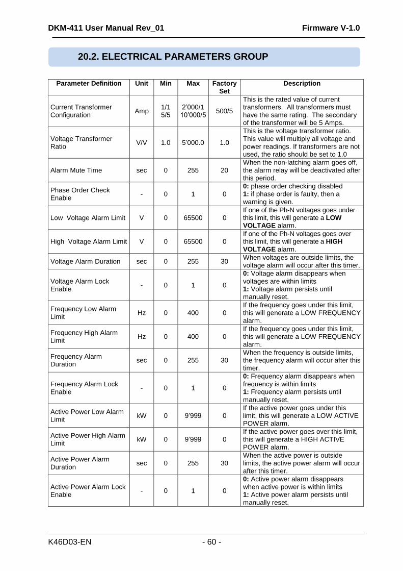
Current Transformer Configuration
Amp 1/1 5/5
2’000/1 10’000/5
500/5
This is the rated value of current transformers. All transformers must have the same rating. The secondary of the transformer will be 5 Amps.
Voltage Transformer Ratio
V/V 1.0 5’000.0 1.0
This is the voltage transformer ratio. This value will multiply all voltage and power readings. If transformers are not used, the ratio should be set to 1.0
Alarm Mute Time sec 0 255 20 When the non-latching alarm goes off, the alarm relay will be deactivated after this period.
Phase Order Check Enable
- 0 1 0 0: phase order checking disabled 1: if phase order is faulty, then a warning is given.
Low Voltage Alarm Limit V 0 65500 0 If one of the Ph-N voltages goes under this limit, this will generate a LOW VOLTAGE alarm.
High Voltage Alarm Limit V 0 65500 0 If one of the Ph-N voltages goes over this limit, this will generate a HIGH VOLTAGE alarm.
Voltage Alarm Duration sec 0 255 30 When voltages are outside limits, the voltage alarm will occur after this timer.
Voltage Alarm Lock Enable
- 0 1 0
0: Voltage alarm disappears when voltages are within limits 1: Voltage alarm persists until manually reset.
Frequency Low Alarm Limit
Hz 0 400 0 If the frequency goes under this limit, this will generate a LOW FREQUENCY alarm.
Frequency High Alarm Limit
Hz 0 400 0 If the frequency goes under this limit, this will generate a LOW FREQUENCY alarm.
Frequency Alarm Duration
sec 0 255 30 When the frequency is outside limits, the frequency alarm will occur after this timer.
Frequency Alarm Lock Enable
- 0 1 0
0: Frequency alarm disappears when frequency is within limits 1: Frequency alarm persists until manually reset.
Active Power Low Alarm Limit
kW 0 9’999 0 If the active power goes under this limit, this will generate a LOW ACTIVE POWER alarm.
Active Power High Alarm Limit
kW 0 9’999 0 If the active power goes over this limit, this will generate a HIGH ACTIVE POWER alarm.
Active Power Alarm Duration
sec 0 255 30 When the active power is outside limits, the active power alarm will occur after this timer.
Active Power Alarm Lock Enable
- 0 1 0
0: Active power alarm disappears when active power is within limits 1: Active power alarm persists until manually reset.
20.2. ELECTRICAL PARAMETERS GROUP
DKM-411 User Manual Rev_01 Firmware V-1.0
K46D03-EN - 61 -
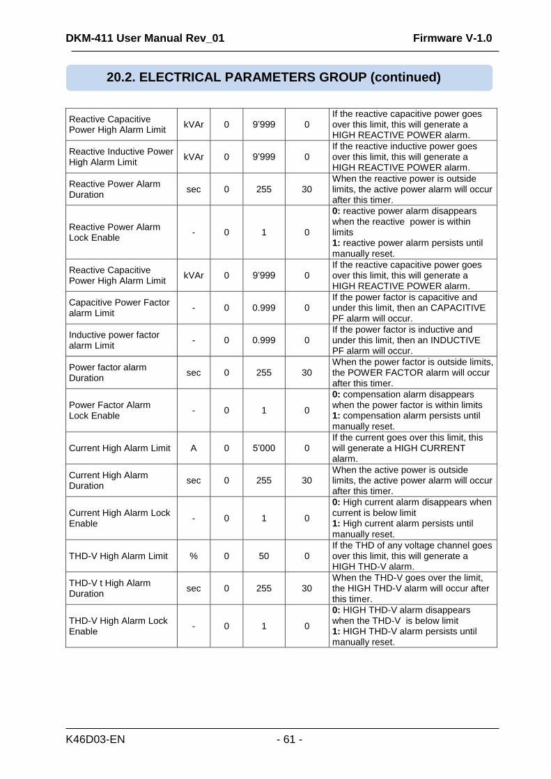
Reactive Capacitive Power High Alarm Limit
kVAr 0 9’999 0 If the reactive capacitive power goes over this limit, this will generate a HIGH REACTIVE POWER alarm.
Reactive Inductive Power High Alarm Limit
kVAr 0 9’999 0 If the reactive inductive power goes over this limit, this will generate a HIGH REACTIVE POWER alarm.
Reactive Power Alarm Duration
sec 0 255 30 When the reactive power is outside limits, the active power alarm will occur after this timer.
Reactive Power Alarm Lock Enable
- 0 1 0
0: reactive power alarm disappears when the reactive power is within limits 1: reactive power alarm persists until manually reset.
Reactive Capacitive Power High Alarm Limit
kVAr 0 9’999 0 If the reactive capacitive power goes over this limit, this will generate a HIGH REACTIVE POWER alarm.
Capacitive Power Factor alarm Limit
- 0 0.999 0 If the power factor is capacitive and under this limit, then an CAPACITIVE PF alarm will occur.
Inductive power factor alarm Limit
- 0 0.999 0 If the power factor is inductive and under this limit, then an INDUCTIVE PF alarm will occur.
Power factor alarm Duration
sec 0 255 30 When the power factor is outside limits, the POWER FACTOR alarm will occur after this timer.
Power Factor Alarm Lock Enable
- 0 1 0
0: compensation alarm disappears when the power factor is within limits 1: compensation alarm persists until manually reset.
Current High Alarm Limit A 0 5’000 0 If the current goes over this limit, this will generate a HIGH CURRENT alarm.
Current High Alarm Duration
sec 0 255 30 When the active power is outside limits, the active power alarm will occur after this timer.
Current High Alarm Lock Enable
- 0 1 0
0: High current alarm disappears when current is below limit 1: High current alarm persists until manually reset.
THD-V High Alarm Limit % 0 50 0 If the THD of any voltage channel goes over this limit, this will generate a HIGH THD-V alarm.
THD-V t High Alarm Duration
sec 0 255 30 When the THD-V goes over the limit, the HIGH THD-V alarm will occur after this timer.
THD-V High Alarm Lock Enable
- 0 1 0
0: HIGH THD-V alarm disappears when the THD-V is below limit 1: HIGH THD-V alarm persists until manually reset.
20.2. ELECTRICAL PARAMETERS GROUP (continued)
DKM-411 User Manual Rev_01 Firmware V-1.0
K46D03-EN - 62 -
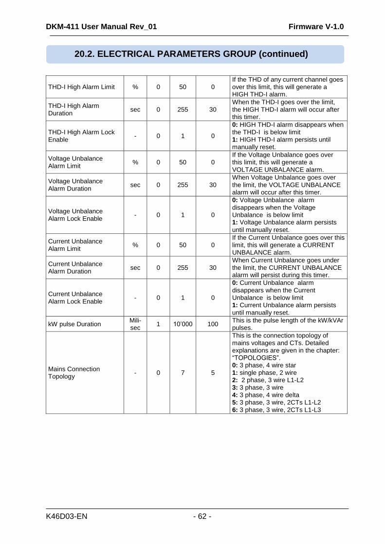
THD-I High Alarm Limit % 0 50 0 If the THD of any current channel goes over this limit, this will generate a HIGH THD-I alarm.
THD-I High Alarm Duration
sec 0 255 30 When the THD-I goes over the limit, the HIGH THD-I alarm will occur after this timer.
THD-I High Alarm Lock Enable
- 0 1 0
0: HIGH THD-I alarm disappears when the THD-I is below limit 1: HIGH THD-I alarm persists until manually reset.
Voltage Unbalance Alarm Limit
% 0 50 0 If the Voltage Unbalance goes over this limit, this will generate a VOLTAGE UNBALANCE alarm.
Voltage Unbalance Alarm Duration
sec 0 255 30 When Voltage Unbalance goes over the limit, the VOLTAGE UNBALANCE alarm will occur after this timer.
Voltage Unbalance Alarm Lock Enable
- 0 1 0
0: Voltage Unbalance alarm disappears when the Voltage Unbalance is below limit 1: Voltage Unbalance alarm persists until manually reset.
Current Unbalance Alarm Limit
% 0 50 0 If the Current Unbalance goes over this limit, this will generate a CURRENT UNBALANCE alarm.
Current Unbalance Alarm Duration
sec 0 255 30 When Current Unbalance goes under the limit, the CURRENT UNBALANCE alarm will persist during this timer.
Current Unbalance Alarm Lock Enable
- 0 1 0
0: Current Unbalance alarm disappears when the Current Unbalance is below limit 1: Current Unbalance alarm persists until manually reset.
kW pulse Duration Mili-sec
1 10’000 100 This is the pulse length of the kW/kVAr pulses.
Mains Connection Topology
- 0 7 5
This is the connection topology of mains voltages and CTs. Detailed explanations are given in the chapter: “TOPOLOGIES”. 0: 3 phase, 4 wire star 1: single phase, 2 wire 2: 2 phase, 3 wire L1-L2 3: 3 phase, 3 wire 4: 3 phase, 4 wire delta 5: 3 phase, 3 wire, 2CTs L1-L2 6: 3 phase, 3 wire, 2CTs L1-L3
20.2. ELECTRICAL PARAMETERS GROUP (continued)
DKM-411 User Manual Rev_01 Firmware V-1.0
K46D03-EN - 63 -
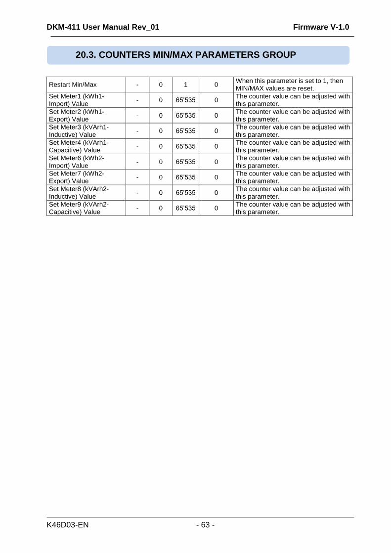
Restart Min/Max - 0 1 0 When this parameter is set to 1, then MIN/MAX values are reset.
Set Meter1 (kWh1-Import) Value
- 0 65’535 0 The counter value can be adjusted with this parameter.
Set Meter2 (kWh1-Export) Value
- 0 65’535 0 The counter value can be adjusted with this parameter.
Set Meter3 (kVArh1-Inductive) Value
- 0 65’535 0 The counter value can be adjusted with this parameter.
Set Meter4 (kVArh1-Capacitive) Value
- 0 65’535 0 The counter value can be adjusted with this parameter.
Set Meter6 (kWh2-Import) Value
- 0 65’535 0 The counter value can be adjusted with this parameter.
Set Meter7 (kWh2-Export) Value
- 0 65’535 0 The counter value can be adjusted with this parameter.
Set Meter8 (kVArh2-Inductive) Value
- 0 65’535 0 The counter value can be adjusted with this parameter.
Set Meter9 (kVArh2-Capacitive) Value
- 0 65’535 0 The counter value can be adjusted with this parameter.
20.3. COUNTERS MIN/MAX PARAMETERS GROUP
DKM-411 User Manual Rev_01 Firmware V-1.0
K46D03-EN - 64 -
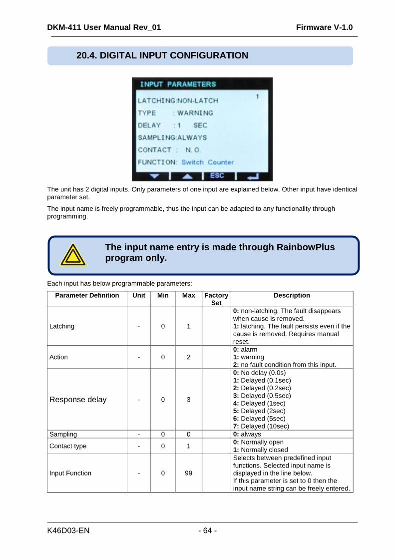
The unit has 2 digital inputs. Only parameters of one input are explained below. Other input have identical parameter set.
The input name is freely programmable, thus the input can be adapted to any functionality through programming.
Each input has below programmable parameters:
Parameter Definition Unit Min Max Factory Set
Description
Latching - 0 1
0: non-latching. The fault disappears when cause is removed. 1: latching. The fault persists even if the cause is removed. Requires manual reset.
Action - 0 2 0: alarm 1: warning 2: no fault condition from this input.
Response delay - 0 3
0: No delay (0.0s) 1: Delayed (0.1sec) 2: Delayed (0.2sec) 3: Delayed (0.5sec) 4: Delayed (1sec) 5: Delayed (2sec) 6: Delayed (5sec) 7: Delayed (10sec)
Sampling - 0 0 0: always
Contact type - 0 1 0: Normally open 1: Normally closed
Input Function - 0 99
Selects between predefined input functions. Selected input name is displayed in the line below. If this parameter is set to 0 then the input name string can be freely entered.
The input name entry is made through RainbowPlus program only.
20.4. DIGITAL INPUT CONFIGURATION
DKM-411 User Manual Rev_01 Firmware V-1.0
K46D03-EN - 65 -
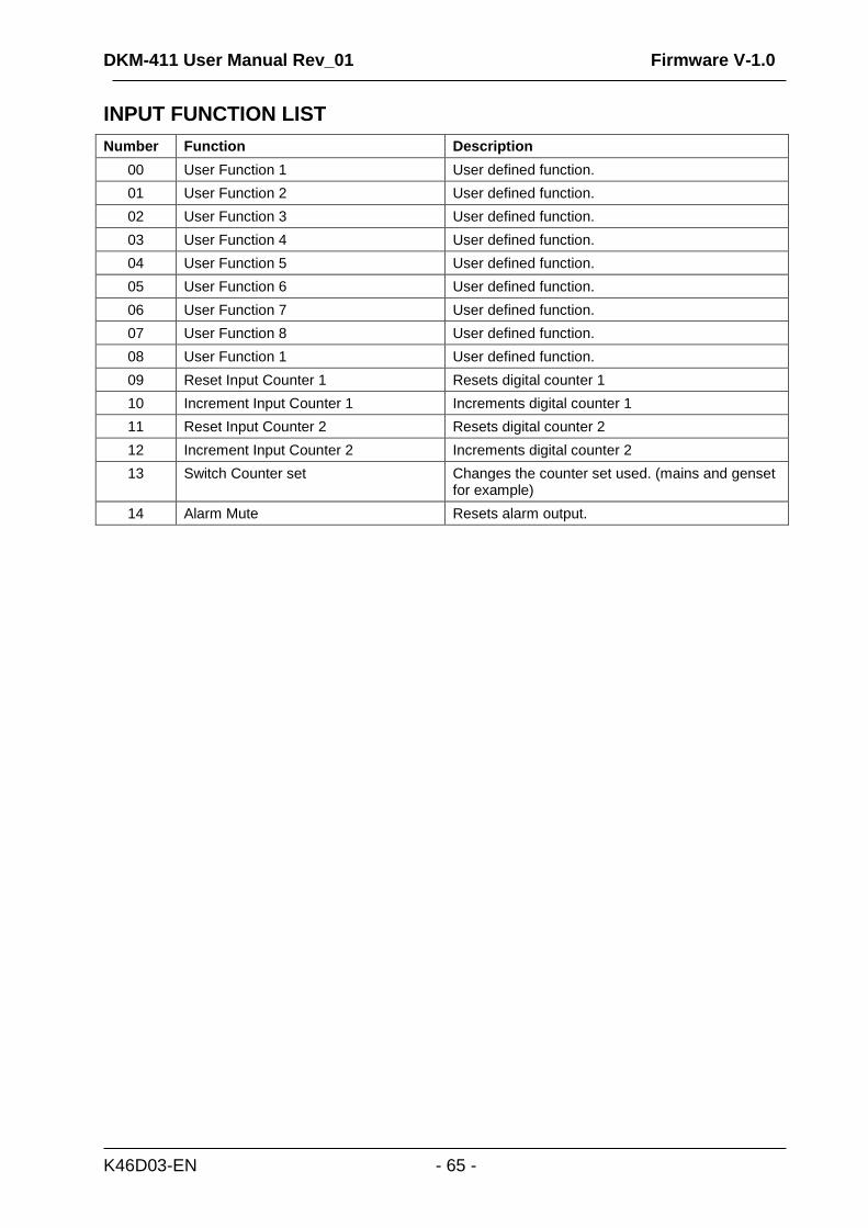
INPUT FUNCTION LIST
Number Function Description
00 User Function 1 User defined function.
01 User Function 2 User defined function.
02 User Function 3 User defined function.
03 User Function 4 User defined function.
04 User Function 5 User defined function.
05 User Function 6 User defined function.
06 User Function 7 User defined function.
07 User Function 8 User defined function.
08 User Function 1 User defined function.
09 Reset Input Counter 1 Resets digital counter 1
10 Increment Input Counter 1 Increments digital counter 1
11 Reset Input Counter 2 Resets digital counter 2
12 Increment Input Counter 2 Increments digital counter 2
13 Switch Counter set Changes the counter set used. (mains and genset for example)
14 Alarm Mute Resets alarm output.
DKM-411 User Manual Rev_01 Firmware V-1.0
K46D03-EN - 66 -
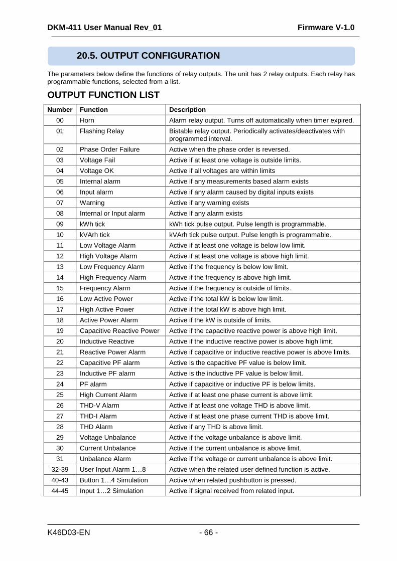
The parameters below define the functions of relay outputs. The unit has 2 relay outputs. Each relay has programmable functions, selected from a list.
OUTPUT FUNCTION LIST
Number Function Description
00 Horn Alarm relay output. Turns off automatically when timer expired.
01 Flashing Relay Bistable relay output. Periodically activates/deactivates with programmed interval.
02 Phase Order Failure Active when the phase order is reversed.
03 Voltage Fail Active if at least one voltage is outside limits.
04 Voltage OK Active if all voltages are within limits
05 Internal alarm Active if any measurements based alarm exists
06 Input alarm Active if any alarm caused by digital inputs exists
07 Warning Active if any warning exists
08 Internal or Input alarm Active if any alarm exists
09 kWh tick kWh tick pulse output. Pulse length is programmable.
10 kVArh tick kVArh tick pulse output. Pulse length is programmable.
11 Low Voltage Alarm Active if at least one voltage is below low limit.
12 High Voltage Alarm Active if at least one voltage is above high limit.
13 Low Frequency Alarm Active if the frequency is below low limit.
14 High Frequency Alarm Active if the frequency is above high limit.
15 Frequency Alarm Active if the frequency is outside of limits.
16 Low Active Power Active if the total kW is below low limit.
17 High Active Power Active if the total kW is above high limit.
18 Active Power Alarm Active if the kW is outside of limits.
19 Capacitive Reactive Power Active if the capacitive reactive power is above high limit.
20 Inductive Reactive Active if the inductive reactive power is above high limit.
21 Reactive Power Alarm Active if capacitive or inductive reactive power is above limits.
22 Capacitive PF alarm Active is the capacitive PF value is below limit.
23 Inductive PF alarm Active is the inductive PF value is below limit.
24 PF alarm Active if capacitive or inductive PF is below limits.
25 High Current Alarm Active if at least one phase current is above limit.
26 THD-V Alarm Active if at least one voltage THD is above limit.
27 THD-I Alarm Active if at least one phase current THD is above limit.
28 THD Alarm Active if any THD is above limit.
29 Voltage Unbalance Active if the voltage unbalance is above limit.
30 Current Unbalance Active if the current unbalance is above limit.
31 Unbalance Alarm Active if the voltage or current unbalance is above limit.
32-39 User Input Alarm 1…8 Active when the related user defined function is active.
40-43 Button 1…4 Simulation Active when related pushbutton is pressed.
44-45 Input 1…2 Simulation Active if signal received from related input.
20.5. OUTPUT CONFIGURATION
DKM-411 User Manual Rev_01 Firmware V-1.0
K46D03-EN - 67 -
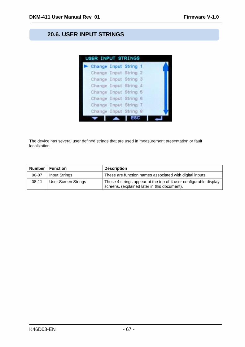
The device has several user defined strings that are used in measurement presentation or fault localization.
Number Function Description
00-07 Input Strings These are function names associated with digital inputs.
08-11 User Screen Strings These 4 strings appear at the top of 4 user configurable display screens. (explained later in this document).
20.6. USER INPUT STRINGS
DKM-411 User Manual Rev_01 Firmware V-1.0
K46D03-EN - 68 -
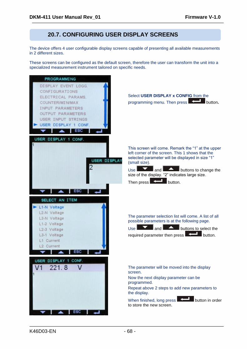
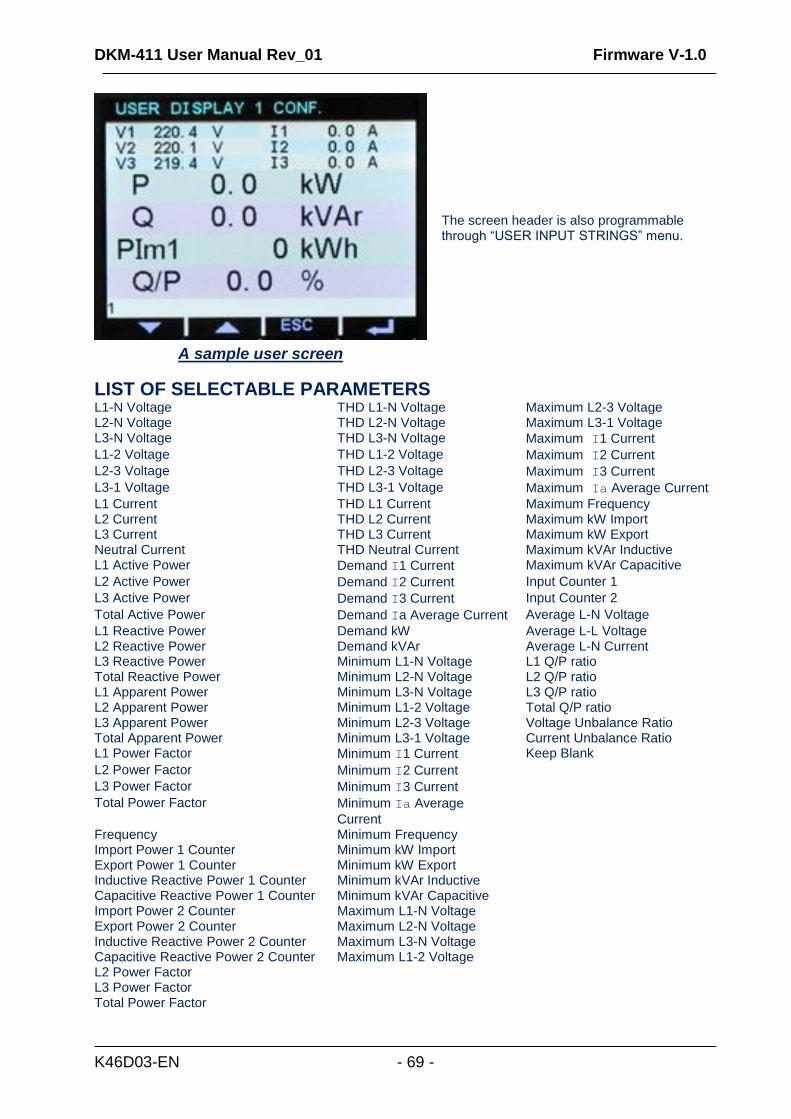
The device offers 4 user configurable display screens capable of presenting all available measurements in 2 different sizes. These screens can be configured as the default screen, therefore the user can transform the unit into a specialized measurement instrument tailored on specific needs.
Select USER DISPLAY x CONFIG from the
programming menu. Then press button.
This screen will come. Remark the “1” at the upper left corner of the screen. This 1 shows that the selected parameter will be displayed in size “1” (small size).
Use and buttons to change the size of the display. “2” indicates large size.
Then press button.
The parameter selection list will come. A list of all possible parameters is at the following page.
Use and buttons to select the
required parameter then press button.
The parameter will be moved into the display screen.
Now the next display parameter can be programmed.
Repeat above 2 steps to add new parameters to the display.
When finished, long press button in order to store the new screen.
20.7. CONFIGURING USER DISPLAY SCREENS
DKM-411 User Manual Rev_01 Firmware V-1.0
K46D03-EN - 69 -
A sample user screen
The screen header is also programmable through “USER INPUT STRINGS” menu.
LIST OF SELECTABLE PARAMETERS L1-N Voltage THD L1-N Voltage Maximum L2-3 Voltage L2-N Voltage THD L2-N Voltage Maximum L3-1 Voltage L3-N Voltage THD L3-N Voltage Maximum I1 Current
L1-2 Voltage THD L1-2 Voltage Maximum I2 Current
L2-3 Voltage THD L2-3 Voltage Maximum I3 Current
L3-1 Voltage THD L3-1 Voltage Maximum Ia Average Current
L1 Current THD L1 Current Maximum Frequency L2 Current THD L2 Current Maximum kW Import L3 Current THD L3 Current Maximum kW Export Neutral Current THD Neutral Current Maximum kVAr Inductive L1 Active Power Demand I1 Current Maximum kVAr Capacitive
L2 Active Power Demand I2 Current Input Counter 1
L3 Active Power Demand I3 Current Input Counter 2
Total Active Power Demand Ia Average Current Average L-N Voltage
L1 Reactive Power Demand kW Average L-L Voltage L2 Reactive Power Demand kVAr Average L-N Current L3 Reactive Power Minimum L1-N Voltage L1 Q/P ratio Total Reactive Power Minimum L2-N Voltage L2 Q/P ratio L1 Apparent Power Minimum L3-N Voltage L3 Q/P ratio L2 Apparent Power Minimum L1-2 Voltage Total Q/P ratio L3 Apparent Power Minimum L2-3 Voltage Voltage Unbalance Ratio Total Apparent Power Minimum L3-1 Voltage Current Unbalance Ratio L1 Power Factor Minimum I1 Current Keep Blank
L2 Power Factor Minimum I2 Current
L3 Power Factor Minimum I3 Current
Total Power Factor Minimum Ia Average
Current
Frequency Minimum Frequency Import Power 1 Counter Minimum kW Import Export Power 1 Counter Minimum kW Export Inductive Reactive Power 1 Counter Minimum kVAr Inductive Capacitive Reactive Power 1 Counter Minimum kVAr Capacitive Import Power 2 Counter Maximum L1-N Voltage Export Power 2 Counter Maximum L2-N Voltage Inductive Reactive Power 2 Counter Maximum L3-N Voltage Capacitive Reactive Power 2 Counter Maximum L1-2 Voltage L2 Power Factor L3 Power Factor Total Power Factor
DKM-411 User Manual Rev_01 Firmware V-1.0
K46D03-EN - 70 -
The site identity string is designed to identify the current device.
This is the site Id string sent at the beginning of SMS messages, e-mails and web page headers for the identification of the device sending the message. Any 20 character string may be entered.
The engine serial number string is designed to identify the current device.
The string is added to GSM-SMS messages, e-mails, web page headers etc.
These telephone number buffers accept up to 16 digits.
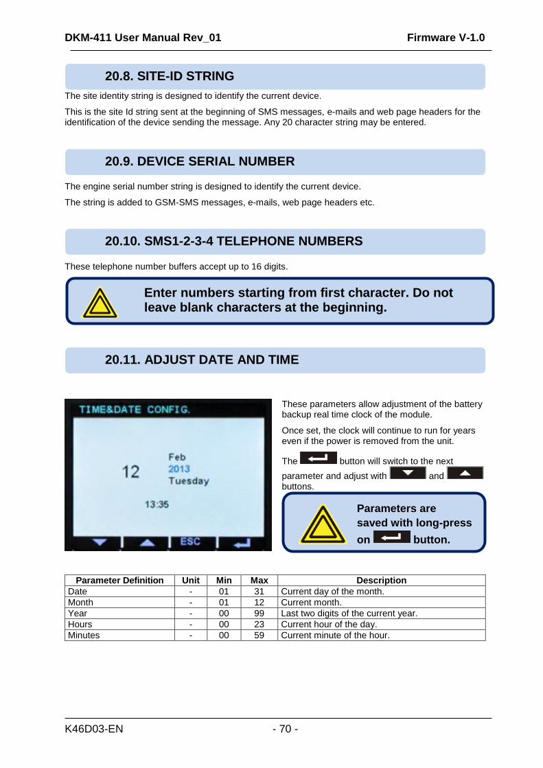
These parameters allow adjustment of the battery backup real time clock of the module.
Once set, the clock will continue to run for years even if the power is removed from the unit.
The button will switch to the next
parameter and adjust with and buttons.
Parameter Definition Unit Min Max Description
Date - 01 31 Current day of the month.
Month - 01 12 Current month.
Year - 00 99 Last two digits of the current year.
Hours - 00 23 Current hour of the day.
Minutes - 00 59 Current minute of the hour.
Parameters are
saved with long-press
on button.
20.8. SITE-ID STRING
20.11. ADJUST DATE AND TIME
Enter numbers starting from first character. Do not leave blank characters at the beginning.
20.10. SMS1-2-3-4 TELEPHONE NUMBERS
20.9. DEVICE SERIAL NUMBER
DKM-411 User Manual Rev_01 Firmware V-1.0
K46D03-EN - 71 -
Parameter Definition Description
APN User Name
The APN (access point name) username may be required by the GSM operator. However some GSM operators may allow access without username. The exact information should be obtained from the GSM operator. Please search the GSM operator’s website with “APN” string.
APN Password
If the APN (access point name) username is required by the GSM operator, most probably the APN password will also be required. However some GSM operators may allow access without password. The exact information should be obtained from the GSM operator. Please search the GSM operator’s website with “APN” string.
APN Name The APN (access point name) is always required by the GSM operator. The exact information should be obtained from the GSM operator. Please search the GSM operator’s website with “APN” string.
SMS Service Center Number
The SMS service center number may be required by the GSM operator. However some GSM operators may allow SMS sending without SMS service center number. The exact information should be obtained from the GSM operator. Please search the GSM operator’s website with “sms service center” string.
Parameter Definition Unit Min Max Factory Set
Description
Modem Selection - 0 1 0 0: not used 1: external GSM Datakom modem
SMS Enable - 0 1 0 0: SMS messages disabled 1: SMS messages enabled
GPRS Connection Enable
- 0 1 0 0: GPRS disabled 1: GPRS enabled
SMS on Output Change - 0 1 0
This parameter controls SMS sending when any output has changed state. No warnings generated. 0: no SMS on output change 1: SMS sent on output change
SMS on IP Change - 0 1 0 0: no SMS on IP address change 1: SMS sent on IP addresschange
SMS Commands Enabled
- 0 1 0 0: SMS commands not accepted 1: SMS commands are accepted but from listed telephone numbers only.
Below GSM modem related parameters are found in the Controller Configuration group.
20.12. GSM MODEM PARAMETERS
DKM-411 User Manual Rev_01 Firmware V-1.0
K46D03-EN - 72 -
Parameter Definition Factory Set Description
Network IP Address 0.0.0.0
This is the IPv4 (internet protocol version 4) address that the unit will require from the DHCP (dynamic host control protocol) server. If this parameter is set to 0.0.0.0 then the unit will require any IPv4 address from the DHCP server. If you are not an IP professional please leave this address as “0.0.0.0”.
Gateway IP Address 0.0.0.0
This is the router IPv4 address, If the Network IP address and Gateway IP Address are set to “0.0.0.0” then the unit will get the gateway address automatically. If you are not an IP professional please leave this address as “0.0.0.0”.
Subnet Mask 255.255.255.0 Reserved for IP professionals. If you are not an IP professional please leave this address as “255.255.255.0”.
User IP Mask 1 (2) (3) 255.255.255.255
0.0.0.0 0.0.0.0
These 3 registers control the IPv4 access to the unit. The remote IPv4 address is logical AND’ed with these IP addresses. If the result gives the remote IP address, then access is enabled. Thus access may be limited to the same LAN members (x.x.x.255) or strictly to predefined IPv4 addresses.
Domain Name d500.dyndns-ip.com
This string is used in “Dynamic DNS” feature. The unit will register itself to the dynamic DNS server under this name. For more detailed information please review chapter on “Dynamic DNS Feature” and the document “Dynamic DNS Account Setting”.
Membership Address members.dyndns.org
This string is used in “Dynamic DNS” feature. This is the address used in registering to the dynamic DNS server. For more detailed information please review chapter on “Dynamic DNS Feature” and the document “Dynamic DNS Account Setting”.
Username/Password
These strings are used in “Dynamic DNS” feature while registering to the dynamic DNS server. For more detailed information please review chapter on “Dynamic DNS Feature” and the document “Dynamic DNS Account Setting”.
Ping Address www.google.com
This internet address is regularly accessed in order to check the availability of internet access. The access period is defined in parameter Controller Configuration>Ping Period.
IP Confirmation Address
checkip.dyndns.org This internet address is regularly accessed in order to read the IPv4 address of the unit.
Rainbow Address-1 Rainbow Address-2
-
These parameters accept both internet addresses (like http://datakom.com.tr) and IPv4 addresses (like 78.192.238.116). Information for remote monitoring is sent to these addresses. The port information of these addresses are found in Controller Configuration group.
20.13. ETHERNET PARAMETERS
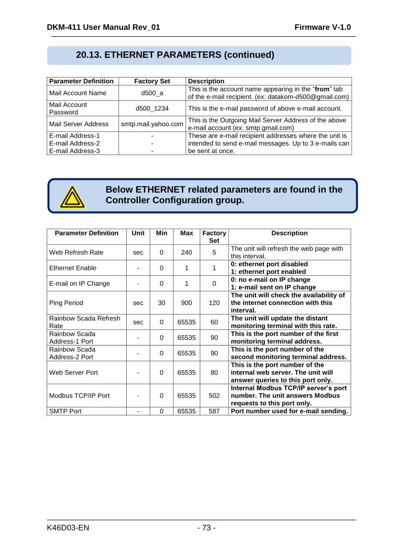
DKM-411 User Manual Rev_01 Firmware V-1.0
K46D03-EN - 73 -
Parameter Definition Factory Set Description
Mail Account Name d500_a This is the account name appearing in the “from” tab of the e-mail recipient. (ex: [email protected])
Mail Account Password
d500_1234 This is the e-mail password of above e-mail account.
Mail Server Address smtp.mail.yahoo.com This is the Outgoing Mail Server Address of the above e-mail account (ex: smtp.gmail.com)
E-mail Address-1 E-mail Address-2 E-mail Address-3
- - -
These are e-mail recipient addresses where the unit is intended to send e-mail messages. Up to 3 e-mails can be sent at once.
Parameter Definition Unit Min Max Factory Set
Description
Web Refresh Rate sec 0 240 5 The unit will refresh the web page with this interval.
Ethernet Enable - 0 1 1 0: ethernet port disabled 1: ethernet port enabled
E-mail on IP Change - 0 1 0 0: no e-mail on IP change 1: e-mail sent on IP change
Ping Period sec 30 900 120 The unit will check the availability of the internet connection with this interval.
Rainbow Scada Refresh Rate
sec 0 65535 60 The unit will update the distant monitoring terminal with this rate.
Rainbow Scada Address-1 Port
- 0 65535 90 This is the port number of the first monitoring terminal address.
Rainbow Scada Address-2 Port
- 0 65535 90 This is the port number of the second monitoring terminal address.
Web Server Port - 0 65535 80 This is the port number of the internal web server. The unit will answer queries to this port only.
Modbus TCP/IP Port - 0 65535 502 Internal Modbus TCP/IP server’s port number. The unit answers Modbus requests to this port only.
SMTP Port - 0 65535 587 Port number used for e-mail sending.
20.13. ETHERNET PARAMETERS (continued)
Below ETHERNET related parameters are found in the Controller Configuration group.
DKM-411 User Manual Rev_01 Firmware V-1.0
K46D03-EN - 74 -
Please see related document: Ethernet Configuration Guide for D-500 D-700.
Please see related document: GSM Configuration Guide for D-500 D-700.
Please see related document: Dynamic DNS Account Setting for D-500 D-700.
21. ETHERNET CONFIGURATION
23. DYNAMIC DNS FEATURE
22. GSM CONFIGURATION
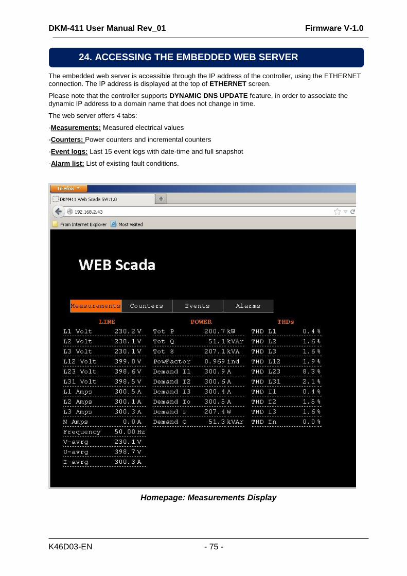
DKM-411 User Manual Rev_01 Firmware V-1.0
K46D03-EN - 75 -
The embedded web server is accessible through the IP address of the controller, using the ETHERNET connection. The IP address is displayed at the top of ETHERNET screen.
Please note that the controller supports DYNAMIC DNS UPDATE feature, in order to associate the dynamic IP address to a domain name that does not change in time.
The web server offers 4 tabs:
-Measurements: Measured electrical values
-Counters: Power counters and incremental counters
-Event logs: Last 15 event logs with date-time and full snapshot
-Alarm list: List of existing fault conditions.
Homepage: Measurements Display
24. ACCESSING THE EMBEDDED WEB SERVER
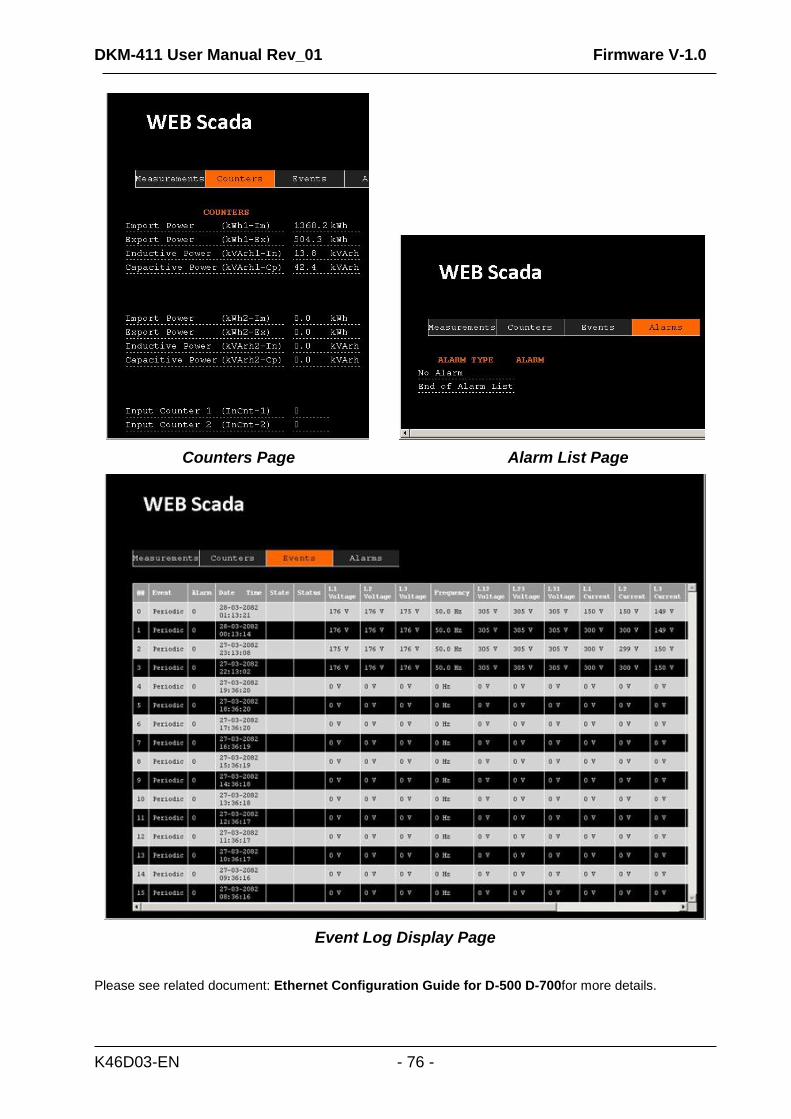
DKM-411 User Manual Rev_01 Firmware V-1.0
K46D03-EN - 76 -
Counters Page Alarm List Page
Event Log Display Page
Please see related document: Ethernet Configuration Guide for D-500 D-700for more details.
DKM-411 User Manual Rev_01 Firmware V-1.0
K46D03-EN - 77 -
Please see related document: Ethernet Configuration Guide for D-500 D-700.
Please see related document: Rainbow Scada Usage Guide.
Please see related document: Ethernet Configuration Guide for D-500 D-700.
This feature is not available yet.
28. ETHERNET/GPRS – MODBUS GATEWAY OPERATION
25. WEB MONITORING
27. E-MAIL SENDING
26. CENTRAL MONITORING
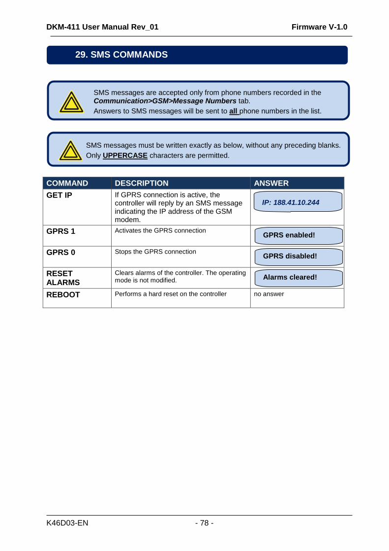
DKM-411 User Manual Rev_01 Firmware V-1.0
K46D03-EN - 78 -
COMMAND DESCRIPTION ANSWER
GET IP
If GPRS connection is active, the controller will reply by an SMS message indicating the IP address of the GSM modem.
GPRS 1 Activates the GPRS connection
GPRS 0 Stops the GPRS connection
RESET ALARMS
Clears alarms of the controller. The operating mode is not modified.
REBOOT Performs a hard reset on the controller
no answer
SMS messages must be written exactly as below, without any preceding blanks.
Only UPPERCASE characters are permitted.
SMS messages are accepted only from phone numbers recorded in the Communication>GSM>Message Numbers tab.
Answers to SMS messages will be sent to all phone numbers in the list.
Alarms cleared!
GPRS disabled!
GPRS enabled!
IP: 188.41.10.244
29. SMS COMMANDS
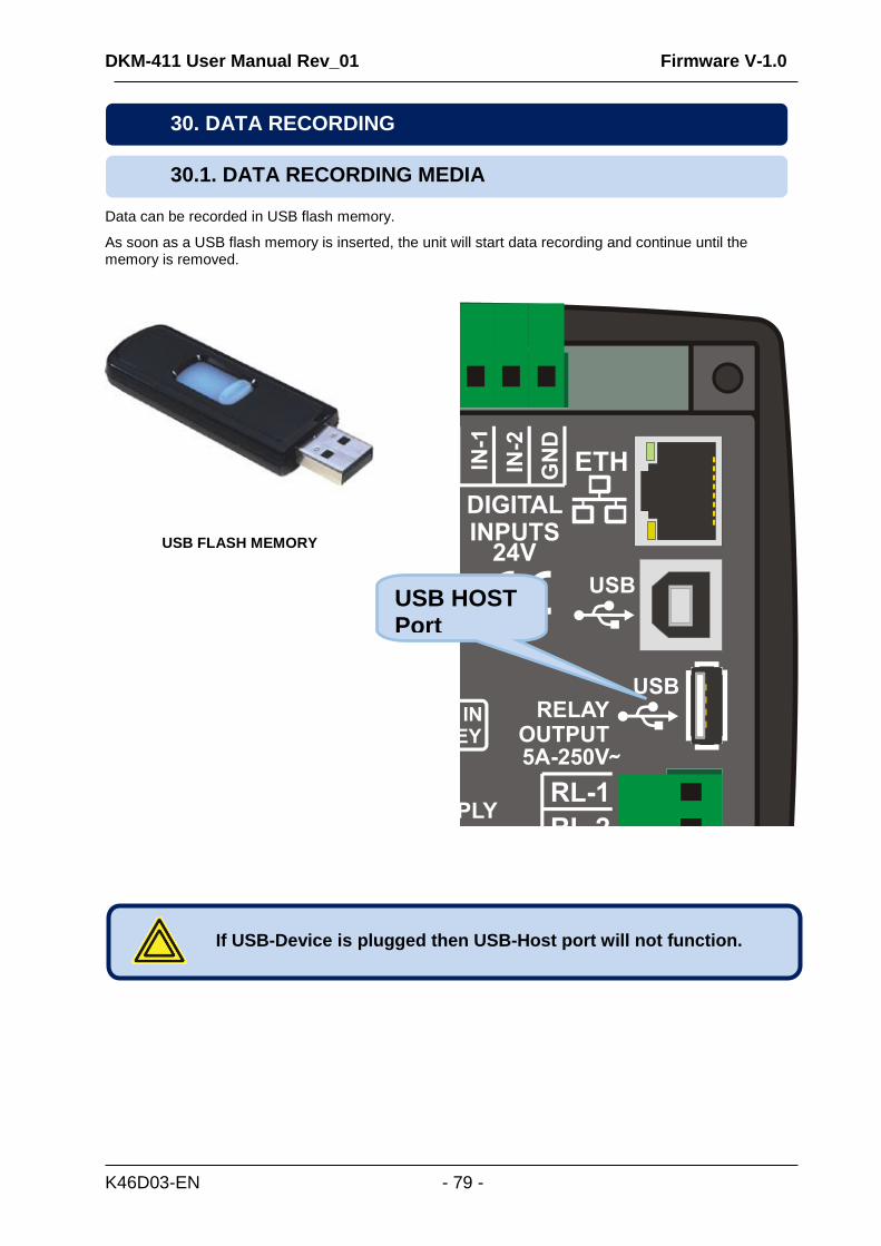
DKM-411 User Manual Rev_01 Firmware V-1.0
K46D03-EN - 79 -
Data can be recorded in USB flash memory.
As soon as a USB flash memory is inserted, the unit will start data recording and continue until the memory is removed.
USB FLASH MEMORY
30.1. DATA RECORDING MEDIA
If USB-Device is plugged then USB-Host port will not function.
30. DATA RECORDING
USB HOST Port
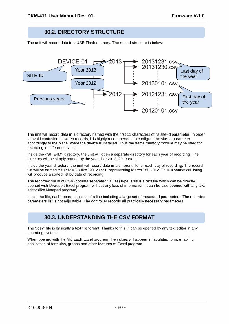
DKM-411 User Manual Rev_01 Firmware V-1.0
K46D03-EN - 80 -
The unit will record data in a USB-Flash memory. The record structure is below:
The unit will record data in a directory named with the first 11 characters of its site-id parameter. In order to avoid confusion between records, it is highly recommended to configure the site-id parameter accordingly to the place where the device is installed. Thus the same memory module may be used for recording in different devices.
Inside the <SITE-ID> directory, the unit will open a separate directory for each year of recording. The directory will be simply named by the year, like 2012, 2013 etc...
Inside the year directory, the unit will record data in a different file for each day of recording. The record file will be named YYYYMMDD like “20120331” representing March ’31, 2012. Thus alphabetical listing will produce a sorted list by date of recording.
The recorded file is of CSV (comma separated values) type. This is a text file which can be directly opened with Microsoft Excel program without any loss of information. It can be also opened with any text editor (like Notepad program).
Inside the file, each record consists of a line including a large set of measured parameters. The recorded parameters list is not adjustable. The controller records all practically necessary parameters.
The “.csv” file is basically a text file format. Thanks to this, it can be opened by any text editor in any operating system.
When opened with the Microsoft Excel program, the values will appear in tabulated form, enabling application of formulas, graphs and other features of Excel program.
30.3. UNDERSTANDING THE CSV FORMAT
30.2. DIRECTORY STRUCTURE
SITE-ID
Year 2013
Year 2012
Previous years
Last day of the year
First day of the year
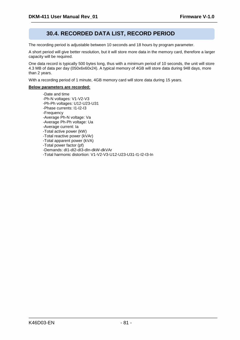
DKM-411 User Manual Rev_01 Firmware V-1.0
K46D03-EN - 81 -
The recording period is adjustable between 10 seconds and 18 hours by program parameter.
A short period will give better resolution, but it will store more data in the memory card, therefore a larger capacity will be required.
One data record is typically 500 bytes long, thus with a minimum period of 10 seconds, the unit will store 4.3 MB of data per day (050x6x60x24). A typical memory of 4GB will store data during 948 days, more than 2 years.
With a recording period of 1 minute, 4GB memory card will store data during 15 years.
Below parameters are recorded:
-Date and time -Ph-N voltages: V1-V2-V3 -Ph-Ph voltages: U12-U23-U31 -Phase currents: I1-I2-I3 -Frequency -Average Ph-N voltage: Va -Average Ph-Ph voltage: Ua -Average current: Ia -Total active power (kW) -Total reactive power (kVAr) -Total apparent power (kVA) -Total power factor (pf) -Demands: dI1-dI2-dI3-dIn-dkW-dkVAr -Total harmonic distortion: V1-V2-V3-U12-U23-U31-I1-I2-I3-In
30.4. RECORDED DATA LIST, RECORD PERIOD
DKM-411 User Manual Rev_01 Firmware V-1.0
K46D03-EN - 82 -
The unit offers the possibility of MODBUS communication through below carriers:
-RS485 serial port, with adjustable baud rate between 2400 and 115200 bauds -MODBUS-TCP/IP through Ethernet port (10/100Mb) -MODBUS-TCP/IP through GPRS (85/42kb), client mode through Rainbow Scada only
The MODBUS properties of the unit are: -Data transfer mode: RTU -Serial data: selectable baud rate, 8 bit data, no parity, 1 bit stop -Modbus-TCP/IP: Ethernet 10/100Mb or GPRS Class 10. -Supported functions: -Function 3 (Read multiple registers) -Function 6 (Write single register)
-Function 16 (Write multiple registers) Each register consists of 2 bytes (16 bits). A larger data structure will contain multiple registers. The Modbus communications requires a slave address to be assigned to each device in the Modbus network. This address ranges between 1 and 240 and allows the addressing of different slave devices in the same network.
This chapter is a brief description of the Modbus properties of the device. For a complete documentation please use:
“DKM-411 Modbus Application Manual”
Devices using Modbus-TCP/IP with different IP or port addresses may use any slave address. It is advised to set these slave addresses to the default setting which is 1.
Each device in the same RS-485 serial network must be assigned a different slave address. Otherwise the Modbus communications will not be performed.
31. MODBUS COMMUNICATIONS
DKM-411 User Manual Rev_01 Firmware V-1.0
K46D03-EN - 83 -
Modbus Slave Address: may be set between 1 and 240 RS-485 Enable: must be set to 1 (or checkbox enabled) RS-485 Baud Rate: selectable between 2400 and 115200 bauds. All devices in the same network must use the same Baud Rate. The complete RS-485 port specifications are found in the D-500/700 User Manual. Selecting a higher baud rate will allow faster communication, but will reduce the communication distance. Selecting a lower baud rate will increase the communication distance, but will cause slower response times. Typically 9600 bauds will allow 1200m distance with special balanced 120 ohms cable.
Modbus Slave Address: may be set between 1 and 240. If only one unit is available in the same IP address, it is advised to keep the default address (1). Ethernet Enable: This parameter should be set to 1 (or checked) in order to enable the ethernet port. Modbus TCP/IP Port: The usual setting is 502. However the unit is able to work on any port address. User IP Mask: There are 3 mask registers available. The use of the registers are emphasized in the D-500/700 User Manual. Please set the first mask as 255.255.255.0 for the proper operation. Ethernet Network IP: May be left as 0.0.0.0 for automatic address claim or set to a value in order to claim a defined address. Ethernet Gateway IP: Should be set in accordance with your local switch configuration. Ethernet Subnet Mask: Should be set in accordance with your local switch configuration. Please rewiev the document Ethernet Configuration Guide for DKM-411 for more details about the ethernet port setup.
16bit variables: These variables are stored in a single register. Bit_0 denotes the LSB and bit 15 denotes the MSB. 32 bit variables: These variables are stored in 2 consecutive registers. The high order 16 bits are in the first register and the low order 16 bits are in the second register Bit arrays: Arrays larger than 16 bits are stored in multiple registers. The LSB of the first register is bit_0. The MSB of the first register is bit_15. The LSB of the second register is bit_16. The MSB of the second register is bit_31, and so on.
31.3. DATA FORMATS
31.2. PARAMETERS REQUIRED FOR MODBUS-TCP/IP VIA ETHERNET
31.1. PARAMETERS REQUIRED FOR RS-485 MODBUS OPERATION
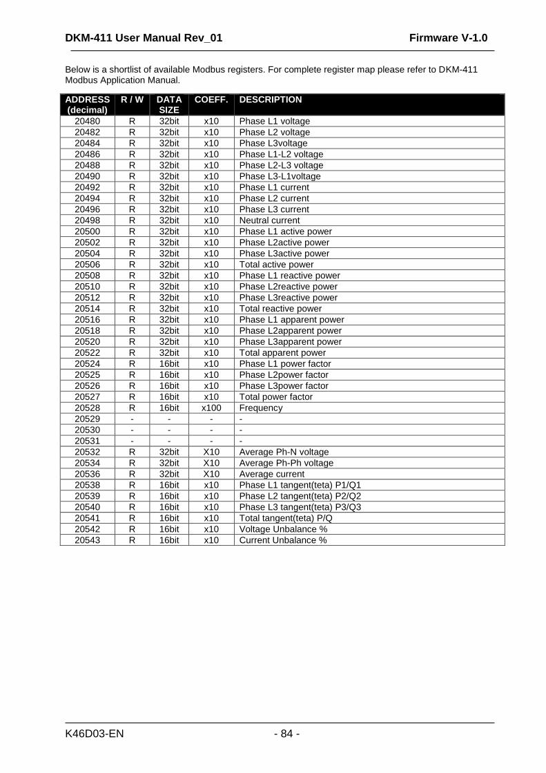
DKM-411 User Manual Rev_01 Firmware V-1.0
K46D03-EN - 84 -
Below is a shortlist of available Modbus registers. For complete register map please refer to DKM-411 Modbus Application Manual.
ADDRESS (decimal)
R / W DATA SIZE
COEFF. DESCRIPTION
20480 R 32bit x10 Phase L1 voltage
20482 R 32bit x10 Phase L2 voltage
20484 R 32bit x10 Phase L3voltage
20486 R 32bit x10 Phase L1-L2 voltage
20488 R 32bit x10 Phase L2-L3 voltage
20490 R 32bit x10 Phase L3-L1voltage
20492 R 32bit x10 Phase L1 current
20494 R 32bit x10 Phase L2 current
20496 R 32bit x10 Phase L3 current
20498 R 32bit x10 Neutral current
20500 R 32bit x10 Phase L1 active power
20502 R 32bit x10 Phase L2active power
20504 R 32bit x10 Phase L3active power
20506 R 32bit x10 Total active power
20508 R 32bit x10 Phase L1 reactive power
20510 R 32bit x10 Phase L2reactive power
20512 R 32bit x10 Phase L3reactive power
20514 R 32bit x10 Total reactive power
20516 R 32bit x10 Phase L1 apparent power
20518 R 32bit x10 Phase L2apparent power
20520 R 32bit x10 Phase L3apparent power
20522 R 32bit x10 Total apparent power
20524 R 16bit x10 Phase L1 power factor
20525 R 16bit x10 Phase L2power factor
20526 R 16bit x10 Phase L3power factor
20527 R 16bit x10 Total power factor
20528 R 16bit x100 Frequency
20529 - - - -
20530 - - - -
20531 - - - -
20532 R 32bit X10 Average Ph-N voltage
20534 R 32bit X10 Average Ph-Ph voltage
20536 R 32bit X10 Average current
20538 R 16bit x10 Phase L1 tangent(teta) P1/Q1
20539 R 16bit x10 Phase L2 tangent(teta) P2/Q2
20540 R 16bit x10 Phase L3 tangent(teta) P3/Q3
20541 R 16bit x10 Total tangent(teta) P/Q
20542 R 16bit x10 Voltage Unbalance %
20543 R 16bit x10 Current Unbalance %
DKM-411 User Manual Rev_01 Firmware V-1.0
K46D03-EN - 85 -
The unit offers the possibility of SNMP communication through its Ethernet port (10/100Mb)
Below parameters may be set to the controller:
Control Buttons Below parameters may be read from the controller:
Voltages (L1, L2, L3, L12, L23, L31) Currents (I1, I2, I3, IN) Active Power (L1, L2, L3, Total) Reactive Power (L1, L2, L3, Total) Apparent Power (L1, L2, L3, Total) Power Factor (L1, L2, L3, Total) Frequency Total kW-h counter-1 Total kVAR-h inductive counter-1 Total kVAR-h capacitive counter-1 Incremental Counter-1 Total kW-h counter-2 Total kVAR-h inductive counter-2 Total kVAR-h capacitive counter-2 Incremental Counter-2 Alarm List Warning List
Modbus Slave Address: may be set between 1 and 240. If only one unit is available in the same IP address, it is advised to keep the default address (1). Ethernet Enable: This parameter should be set to 1 (or checked) in order to enable the ethernet port. Modbus TCP/IP Port: The usual setting is 502. However the unit is able to work on any port address. User IP Mask: There are 3 mask registers available. The use of the registers are emphasized in the DKM-411 User Manual. Please set the first mask as 255.255.255.0 for the proper operation. Ethernet Network IP: May be left as 0.0.0.0 for automatic address claim or set to a value in order to claim a defined address. Ethernet Gateway IP: Should be set in accordance with your local switch configuration. Ethernet Subnet Mask: Should be set in accordance with your local switch configuration. The complete Ethernet port specifications are found in the DKM-411 User Manual. Please rewiev the document Ethernet Configuration Guide for DKM-411 for more details about the ethernet port setup.
The supported version of the SNMP is V1.0.
32.1. PARAMETERS REQUIRED FOR SNMP VIA ETHERNET
The SNMP MIB file is available at Datakom Technical support.
32. SNMP COMMUNICATIONS
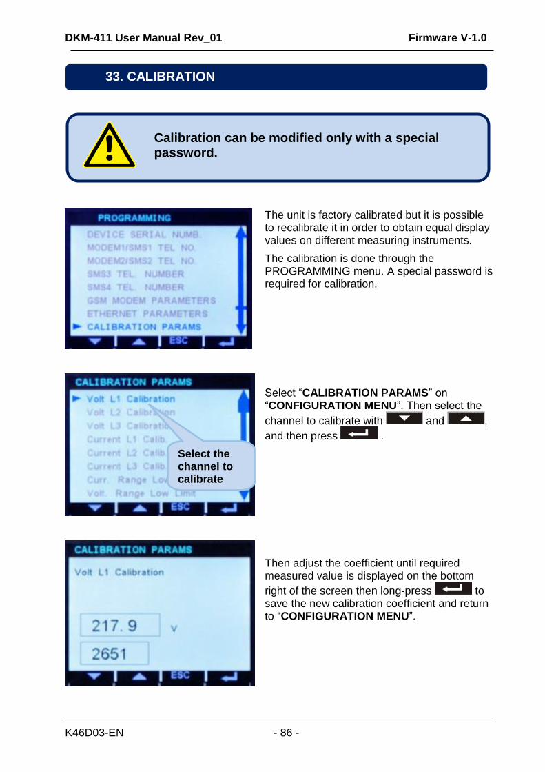
DKM-411 User Manual Rev_01 Firmware V-1.0
K46D03-EN - 86 -
The unit is factory calibrated but it is possible to recalibrate it in order to obtain equal display values on different measuring instruments.
The calibration is done through the PROGRAMMING menu. A special password is required for calibration.
Select “CALIBRATION PARAMS” on “CONFIGURATION MENU”. Then select the
channel to calibrate with and ,
and then press .
Then adjust the coefficient until required measured value is displayed on the bottom
right of the screen then long-press to save the new calibration coefficient and return to “CONFIGURATION MENU”.
Calibration can be modified only with a special password.
33. CALIBRATION
Select the channel to calibrate
DKM-411 User Manual Rev_01 Firmware V-1.0
K46D03-EN - 87 -
The unit conforms to the EU directives
-2006/95/EC (low voltage)
-2004/108/EC (electro-magnetic compatibility)
Norms of reference:
EN 61010 (safety requirements)
EN 61326 (EMC requirements)
The CE mark indicates that this product complies with the European requirements for safety, health,
environmental and customer protection.
UL / CSA Conformity: certification teting in progress UL 508, Edition 17 UL 2200, 1st Edition. UL 840 Edition 3 CSA C22.2 NO. 14 - Edition 10
Repair can be performed by the manufacturer only. Calibration may be verified or done during operation.
Wipe the unit, if necessary with a soft damp cloth. Do not use chemical agents.
The device is subject to detailed safety and quality checks before shipment.
When a device is opened, checks must be done again in full.
Internal battery
The internal real time clock /RTC) is supplied with power from the auxiliary supply voltage. If the device is not powered on, the RTC is supplied by the internal lithium battery (CR2032 type). The lifetime of the battery is minimum 5 years, the expected life is 8 to 10 years.
Internal battery is replaced by the manufacturer only.
34. DECLARATION OF CONFORMITY
Opening a device will cancel the warranty.
DO NOT OPEN THE UNIT !
There are NO serviceable parts inside the unit.
35. MAINTENANCE
DKM-411 User Manual Rev_01 Firmware V-1.0
K46D03-EN - 88 -
Following DIRECTIVE 2002/96/EC OF THE EUROPEAN PARLIAMENT AND OF THE COUNCIL of 27
January 2003 on waste electrical and electronic equipment (WEEE), this unit should be stored and disposed separately from the usual waste.
The internal lithium battery must be disposed off separately.
The european ROHS directive restricts and prohibits the use of some chemical materials in electronic devices.
Following the “DIRECTIVE 2011/65/EU OF THE EUROPEAN PARLIAMENT AND OF THE COUNCIL of 8 June 2011 on the restriction of the use of certain hazardous substances in electrical and electronic equipment”, this product is listed in annex-I under category: “Monitoring and control instruments including industrial monitoring and control instruments” and exempted from ROHS directive. However Datakom is not using any ROHS uncompliant electronic components in the production. Only the solder contains lead. The switching to unleaded solderin is in progress.
37. ROHS COMPLIANCE
36. DISPOSAL OF THE UNIT
DKM-411 User Manual Rev_01 Firmware V-1.0
K46D03-EN - 89 -
No display:
External fusing for the power supply voltage has tripped. Switch fuse on or replace fuse.
Incorrect auxiliary supply voltage, check voltage at power supply terminals.
Incorrect power supply polarity for DC supply versions.
Device is defective. Send device to the manufacturer for repair.
Incorrect voltage display:
Measured voltages are not connected. Connect measuring-circuit voltages.
Important! Ensure the measurement inputs are not overloaded.
The voltage measuring range has been exceeded. Check device ratings.
The voltage measuring range has been exceeded by harmonic components. Check harmonics.
Connect voltage transformer if necessary.
Incorrect phase connections. Check wiring.
Voltage transformer ratio incorrectly programmed. Check program parameter and voltage transformer.
Device is defective. Send device to the manufacturer for repair.
Incorrect current display:
Measured currents are not connected. Connect measuring-circuit current inputs.
Important! Ensure the measurement inputs are not overloaded.
The current measuring range has been exceeded. Check device ratings.
The current measuring range has been exceeded by harmonic components. Check harmonics.
Incorrect phase connections. Check wiring.
Current transformer ratio incorrectly programmed. Check program parameter and current transformer ratings.
Device is defective. Send device to the manufacturer for repair.
Below is a basic list of most often encountered troubles. More detailed investigation may be required in some cases.
38. TROUBLESHOOTING GUIDE
DKM-411 User Manual Rev_01 Firmware V-1.0
K46D03-EN - 90 -
Incorrect active/reactive power and power factor display:
Check voltage and current displays. If incorrect, follow above instructions.
Current transformers are not connected to correct inputs or some CTs are connected with reverse polarity. Determine the correct connections of each individual CT in order to obtain correct KW and power factor display for the related phase.
Please review chapter: “AC CURRENT INPUTS”
Measured currents are not connected. Connect measuring-circuit current inputs.
Important! Ensure the measurement inputs are not overloaded.
The current measuring range has been exceeded. Check device ratings.
The current measuring range has been exceeded by harmonic components. Check harmonics.
Incorrect phase connections. Check wiring.
Current transformer ratio incorrectly programmed. Check program parameter and current transformer ratings.
Device is defective. Send device to the manufacturer for repair.
RS-485 connection does not work:
Check polarity of A-B terminals.
Incorrect device address.
Missing termination resistors. Terminate bus with 120 ohm resistors from both ends.
Incorrect baud rate selection. Select correct baud rate.
RS-485 port not enabled. Check program parameter.
Device is defective. Send device to the manufacturer for repair.
Programming mode can not be entered:
Enter correct password. Try with “3282” as password.
Some program parameters are skipped:
These parameters require a higher level of password.