Embed Size (px)
Citation preview
MD ANDERSON Project No. 16-0271 SRB AND PPB BOILER BLOWDOWN PIPING MDACC FP D&C Issued for Construction September 28, 2017
The University of Texas TABLE OF CONTENTS MD Anderson Cancer Center 00 01 10 MS080415 1 OF 2
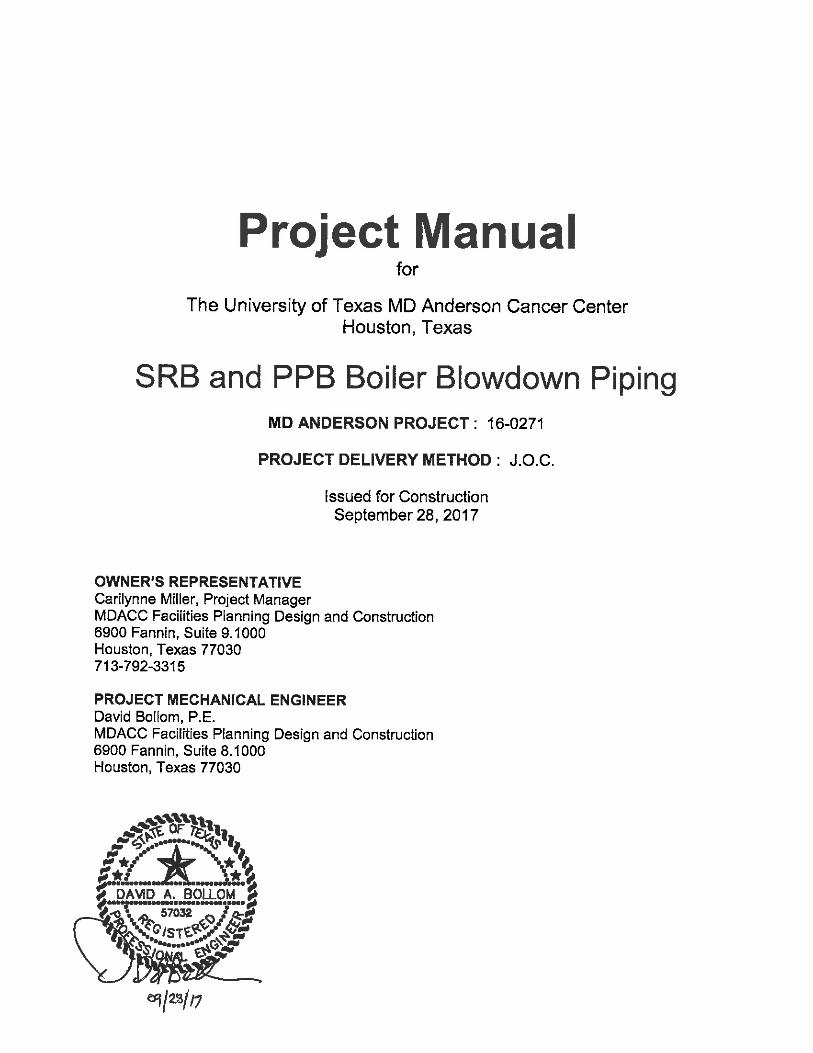
PROJECT MANUAL TABLE OF CONTENTS
A – PROCUREMENT AND CONTRACTING REQUIREMENTS GROUP DIVISION 00 PROCUREMENT AND CONTRACTING REQUIREMENTS
2013 Uniform General Conditions for University of Texas System Building Construction Contracts
Issued by Owner under separate cover for Contractor Procurement
00 25 00 Owners Special Conditions Issued by Owner under separate cover for Contractor Procurement
00 25 00 A Attachment “A” - Minimum Wage Rate Determination Issued by Owner under separate cover for Contractor Procurement
00 25 00 B Attachment “B” - Facilities Planned Utility Outages Policy Issued by Owner under separate cover for Contractor Procurement
00 25 00 C Attachment “C” - Project Sign Layout Issued by Owner under separate cover for Contractor Procurement
00 25 00 D Attachment “D” - Bastrop Visitation and Tour Policy Statement and Medical Documentation Requirements
Issued by Owner under separate cover for Contractor Procurement
00 73 16 Project Insurance (OCIP) Issued by Owner under separate cover for Contractor Procurement
B - SPECIFICATIONS GROUP
DIVISION 01 GENERAL REQUIREMENTS 01 31 00 Project Administration
Issued by Owner under separate cover for Contractor Procurement
01 32 00 Project Planning and Scheduling Issued by Owner under separate cover for Contractor Procurement
01 35 16 Alteration Project Procedures Issued by Owner under separate cover for Contractor Procurement
01 35 23 Project Safety (OCIP) Issued by Owner under separate cover for Contractor Procurement
01 35 25 Owner Safety Requirements Issued by Owner under separate cover for Contractor Procurement
MD ANDERSON Project No. 16-0271 SRB AND PPB BOILER BLOWDOWN PIPING MDACC FP D&C Issued for Construction September 28, 2017
The University of Texas TABLE OF CONTENTS MD Anderson Cancer Center 00 01 10 MS080415 2 OF 2
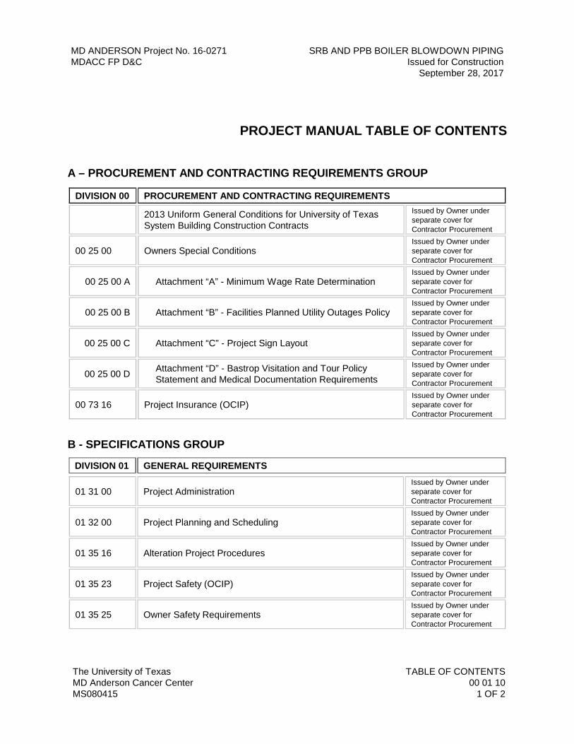
DIVISION 01 GENERAL REQUIREMENTS
01 35 25 A Attachment “A” - Maintaining Indoor Air Quality During Construction And Maintenance Activities Policy
Issued by Owner under separate cover for Contractor Procurement
01 45 00 Project Quality Control Issued by Owner under separate cover for Contractor Procurement
01 57 23 Temporary Storm Water Pollution Control Issued by Owner under separate cover for Contractor Procurement
01 57 25 Dust Control Plan Issued by Owner under separate cover for Contractor Procurement
01 77 00 Project Closeout Procedures Issued by Owner under separate cover for Contractor Procurement
01 79 00 Demonstration and Training Issued by Owner under separate cover for Contractor Procurement
01 89 23 Site HVAC Utilities Performance Requirements Issued by Owner under separate cover for Contractor Procurement
01 91 00 General Commissioning Requirements Issued by Owner under separate cover for Contractor Procurement
DIVISION 20 COMMON FIRE SUPPRESSION, PLUMBING AND HVAC REQUIREMENTS REVISION
20 01 00 Basic Fire Suppression, Plumbing and HVAC Requirements
20 05 29 Supports and Sleeves
20 07 16 Equipment Insulation
20 07 19 Piping Insulation
DIVISION 23 HEATING, VENTILATING, AND AIR CONDITIONING REVISION 23 21 13 Hydronic Piping
23 22 13 Steam and Steam Condensate Piping
23 22 30 Steam and Condensate Specialties
END OF SECTION 00 01 10
MD ANDERSON Project No. 16-0271 SRB AND PPB BOILER BLOWDOWN PIPING MDACC FP D&C Issued for Construction September 28, 2017
The University of Texas MD Anderson Cancer Center
BASIC FIRE SUPPRESSION, PLUMBING AND HVAC REQUIREMENTS
20 01 00 MS081811 1 OF 8
SECTION 20 01 00 – BASIC FIRE SUPPRESSION, PLUMBING AND HVAC REQUIREMENTS
PART 1 - GENERAL
1.01 RELATED DOCUMENTS
A. Drawings and general provisions of the Contract, including General Conditions and Division 01 Specification Sections, apply to this Section.
B. Specifications throughout all Divisions of the Project Manual are directly applicable to this Section, and this Section is directly applicable to them.
1.02 SUMMARY
A. Basic and supplemental requirements common to Fire Suppression, Plumbing and HVAC Work.
1.03 REFERENCE STANDARDS
A. The latest published edition of a reference shall be applicable to this Project unless identified by a specific edition date.
B. All reference amendments adopted prior to the effective date of this Contract shall be applicable to this Project.
C. All materials, installation and workmanship shall comply with the applicable requirements and standards addressed within the Contract Documents.
1.04 DEFINITIONS
A. These definitions are included to clarify the direction and intention of these Specifications. For further clarification, contact the Architect/Engineer.
1. Concealed / Exposed: "Concealed" areas are those areas that cannot be seen by the building occupants. "Exposed" areas are all areas, which are exposed to view by the building occupants, including under counters, inside cabinets and closets, plus all mechanical rooms. “Exterior” areas are those that are outside the building exterior envelope and exposed to the outdoors.
2. Furnish: The term "furnish" is used to mean "supply and deliver to the Project Site, ready for unloading, unpacking, assembly, installation, and similar operations.
3. Install: The term "install" is used to describe operations at Project Site including the actual "unloading, unpacking, assembly, erection, placing, anchoring, applying, working to dimension, finishing, curing, protecting, cleaning, and similar operations.
4. Provide: The term "provide" means "to furnish and install, complete and ready for the intended use.
MD ANDERSON Project No. 16-0271 SRB AND PPB BOILER BLOWDOWN PIPING MDACC FP D&C Issued for Construction September 28, 2017
The University of Texas MD Anderson Cancer Center
BASIC FIRE SUPPRESSION, PLUMBING AND HVAC REQUIREMENTS
20 01 00 MS081811 2 OF 8
1.05 QUALITY ASSURANCE
A. Fire Suppression, Plumbing and HVAC systems shall be coordinated with other systems and trades to include but not be limited to: Electrical systems, fire alarm, security systems, transport systems, telephone and data systems.
B. Verification of Dimensions: The Contractor shall be responsible for the coordination and proper relation of Contractor’s Work to the building structure and to the Work of all trades. The Contractor shall visit the premises and become thoroughly familiar with all details of the Work and working conditions, to verify all dimensions in the field, and to advise the Architect/Engineer of any discrepancy before performing any Work. Adjustments to the Work required in order to facilitate a coordinated installation shall be made at no additional cost to the Owner or the Architect/Engineer.
C. All dimensional information related to new structures shall be taken from the appropriate Drawings. All dimensional information related to existing facilities shall be taken from actual measurements made by the Contractor on the Site.
D. The Drawings are subject to the requirements of Reference Standards, structural and architectural conditions. The Contractor shall carefully investigate structural and finish conditions and shall coordinate the separate trades in order to avoid interference between the various phases of Work. Work shall be organized and laid out so that it will be concealed in furred chases and suspended ceilings, etc., in finished portions of the building, unless specifically noted to be exposed. All exposed Work shall be installed parallel or perpendicular to the lines of the building unless otherwise noted.
E. When the Drawings do not give exact details as to the elevation of pipe and ducts, the Contractor shall physically arrange the systems to fit in the space available at the elevations intended with proper grades for the functioning of the system involved. Piping and duct systems are generally intended to be installed true and square to the building construction, and located as high as possible against the structure in a neat and workmanlike manner. The Drawings do not show all required offsets, control lines, pilot lines and other location details. Work shall be concealed in all finished areas.
F. Where core drilling of floor or wall penetrations is required, Work shall be performed in accordance with Division 03 Specifications. Where applicable Division 03 Specifications are not included in the Project, core drilling shall be in accordance with generally accepted standards, and be performed by licensed personnel where applicable.
G. Certify in writing that neither the Contractor nor any of Contractor’s subcontractors or suppliers will supply any materials that contain any asbestos in any form for this Project.
1.06 DELIVERY, STORAGE AND HANDLING
A. All equipment, ductwork, and materials shall be delivered to the Project Site clean and sealed for protection.
B. Take particular care not to damage the existing construction in performing Work. All finished floors, step treads and finished surfaces shall be covered to prevent any damage by workers or their tools and equipment during the construction of the Project.
MD ANDERSON Project No. 16-0271 SRB AND PPB BOILER BLOWDOWN PIPING MDACC FP D&C Issued for Construction September 28, 2017
The University of Texas MD Anderson Cancer Center
BASIC FIRE SUPPRESSION, PLUMBING AND HVAC REQUIREMENTS
20 01 00 MS081811 3 OF 8
C. Equipment and materials shall be protected from rust and dust/debris both before and after installation. Any equipment or materials found in a rusty condition at the time of final inspection must be cleaned of rust and repainted as specified elsewhere in these Specifications.
D. All material affected by weather shall be covered and protected to keep the material free from damage while material is being transported to the Site and while stored at the Project Site.
E. During the execution of the Work, open ends of all piping and conduit, and all openings in equipment shall be closed when Work is not in progress, and shall be capped and sealed prior to completion of final connections, so as to prevent the entrance of foreign matter.
F. All equipment shall be protected during the execution of the Work. All ductwork and equipment shall be sealed with heavy plastic and tape to prevent build-up of dust and debris.
G. All ductwork and air handling equipment shall be wiped down with a damp cloth immediately before installation to ensure complete removal of accumulated dusts and foreign matter.
H. All plumbing fixtures shall be protected and covered to prohibit usage. All drains shall be covered until placed in service to prevent the entrance of foreign matter.
PART 2 - PRODUCTS
2.01 GENERAL
A. All materials shall meet or exceed all applicable referenced standards, federal, state and local requirements, and conform to codes and ordinances of authorities having jurisdiction.
B. All equipment installed shall have local representation, local factory authorized service, and a local stock of repair parts.
C. Responsibility for furnishing proper equipment and/or material and ensuring that equipment and/or material is installed as intended by the manufacturer, rests entirely upon the Contractor. Contractor shall request advice and supervisory assistance from the representative of specific manufacturers during the installation.
D. All materials, unless otherwise specified, shall be new, free from all defects, suitable for the intended use and of the best quality of their respective kinds. Materials and equipment shall be installed in accordance with the manufacturer's recommendations and the best standard practice for the type of Work involved. All Work shall be executed by mechanics skilled in their respective trades, and the installations shall provide a neat, precise appearance. Materials and/or equipment damaged in shipment or otherwise damaged prior to installation shall not be repaired at the job Site but shall be replaced with new materials and/or equipment.
E. Materials and equipment manufactured domestically are preferred when possible. Materials and equipment that are not available from a domestic manufacturer may be by a non-domestic manufacturer provided they fully comply with Contract Documents.
F. Prevention of Rust: Standard factory finish will be acceptable on equipment specified by model number; otherwise, surfaces of ferrous metal shall be given a rust inhibiting coating.
MD ANDERSON Project No. 16-0271 SRB AND PPB BOILER BLOWDOWN PIPING MDACC FP D&C Issued for Construction September 28, 2017
The University of Texas MD Anderson Cancer Center
BASIC FIRE SUPPRESSION, PLUMBING AND HVAC REQUIREMENTS
20 01 00 MS081811 4 OF 8
2.02 NAMEPLATES
A. Each major component of equipment shall have the manufacturer's name, address, and catalog number on a plate securely attached to the item of equipment. All data on nameplates shall be legible at the time of Final Inspection.
B. Nameplates shall be black laminated rigid phenolic with white core. Nameplate minimum size shall be 1 inch high by 3 inches long with 3/16-inch-high engraved white letters.
C. Nameplate Fasteners: Fasten nameplates to the front of equipment only by means of stainless steel self-tapping screws. Stick-ons or adhesives will not be allowed unless the NEMA enclosure rating is compromised, then only epoxy adhesive shall be used to attach nameplates.
D. Nameplate Information: In general, the following information is to be provided for the types of electrical components or enclosures supplied with equipment.
1. Individual Starters, Contactors, Disconnect Switches, and Similar Equipment: Identify the device, and voltage characteristics source and load served.
2.03 WALL, FLOOR AND CEILING PLATES (ESCUTCHEONS)
A. Except as otherwise noted, provide stainless steel or chrome plated brass floor and ceiling plates around all pipes, ducts, conduits, etc., passing exposed through walls, floors or ceilings, in any spaces except underfloor and plenum spaces.
B. Plates shall be sized to fit snugly against the outside of the pipe or against the insulation on lines that are insulated and positively secured to such pipe or insulation.
C. For finished ceiling installation, secure escutcheons to ceiling with escutcheon fasteners.
D. Plates will not be required for piping where pipe sleeves extend ¾-inch or more above finished floor.
E. Round and rectangular ducts shall have closure plates (not chrome plated) made to fit accurately at all floor, wall and ceiling penetrations.
2.04 ROOF PENETRATIONS AND FLASHING
A. Pipe, conduit and duct sleeves, pitch pockets and flashings compatible with the roofing installation shall be provided and installed for all roof penetrations by a contractor qualified in such Work. Installation shall comply with the Contract Documents and with FM General Data Sheets 1-28, 1-29, 1-31 & 1-49 along with the FM approval guide.
PART 3 - EXECUTION
3.01 PREPARATION
A. Cooperate with trades of adjacent, related or affected materials or operations, and with trades performing continuations of this Work in order to effect timely and accurate placing of Work and to coordinate, in proper and correct sequence, the Work of such trades.
MD ANDERSON Project No. 16-0271 SRB AND PPB BOILER BLOWDOWN PIPING MDACC FP D&C Issued for Construction September 28, 2017
The University of Texas MD Anderson Cancer Center
BASIC FIRE SUPPRESSION, PLUMBING AND HVAC REQUIREMENTS
20 01 00 MS081811 5 OF 8
B. The size of equipment indicated on the Drawings is based on the dimensions of a particular manufacturer. While other manufacturers may be acceptable, it is the responsibility of the Contractor to determine that the equipment proposed will fit in the space. Fabrication Drawings shall be prepared when required by the Architect/Engineer or Owner to indicate a suitable arrangement.
C. All equipment shall be installed in a manner to permit access to all surfaces. All valves, motors, drives, filters, and other accessory items shall be installed in a position to allow removal for service without disassembly of another part.
D. Space Requirements:
1. Consider space limitations imposed by contiguous Work in location of equipment and material. Do not provide equipment or material which is not suitable in this respect.
2. Make changes in material and equipment locations of up to five (5) feet, to allow for field conditions prior to actual installation, and as directed by the Architect/Engineer at no additional cost to the Owner.
E. Contractor shall note that the electrical design and Drawings are based on the equipment scheduled and indicated on the Drawings. Should any equipment be provided requiring changes to the electrical design, the required electrical changes shall be made at no cost to the Owner.
F. Connections for equipment other than Divisions 21, 22, 23:
1. Rough-in and provide all gas, air, water, steam, sewer, etc. connections to all fixtures, equipment, machinery, etc., furnished by the Owner and/or other trades in accordance with detailed rough-in Drawings provided by the equipment suppliers, by actual measurements of the equipment connections, or as detailed.
2. After the equipment is set in place, make all final connections and provide all required pipe, fittings, valves, traps, etc.
3. Provide all backflow preventers and air gap fittings required, using approved devices. In each service line connected to an item of equipment or piece of machinery, provide a shutoff valve. On each drain not provided with a trap, provide a suitable trap.
4. Provide all ductwork, transition pieces, etc., required for a complete installation of vent hoods, fume hoods, etc.
3.02 INSTALLATION
A. Installation shall meet or exceed all applicable federal, state and local requirements, referenced standards and conform to codes and ordinances of authorities having jurisdiction.
B. All installation shall be in accordance with manufacturer’s published recommendations.
C. Piping may be run exposed in rooms typically without ceilings such as mechanical rooms, janitor's closets, tight against pan soffits in exposed "tee" structures, or storage spaces, but only where necessary. Shutoff and isolation valves shall be easily accessible.
MD ANDERSON Project No. 16-0271 SRB AND PPB BOILER BLOWDOWN PIPING MDACC FP D&C Issued for Construction September 28, 2017
The University of Texas MD Anderson Cancer Center
BASIC FIRE SUPPRESSION, PLUMBING AND HVAC REQUIREMENTS
20 01 00 MS081811 6 OF 8
D. All pipe, conduits, etc., shall be cut accurately to measurements established at the building and shall be worked into place without springing or forcing. All ducts, pipes and conduits run exposed in machinery and equipment rooms shall be installed parallel to the building lines, except that piping shall be sloped to obtain the proper pitch. Piping and ducts run in furred ceilings, etc., shall be similarly installed, except as otherwise shown. All pipe openings shall be kept closed until the systems are closed with final connections.
E. Prior to the installation of any ceiling material, gypsum, plaster or acoustical board, the Contractor shall notify Owner’s Project Manager so that arrangement can be made for an inspection of the above-ceiling area about to be "sealed" off. The Contractor shall provide written notification to the Owner at least five (5) calendar days prior to the inspection.
F. Precedence of Materials:
1. The Specifications determine the nature and setting of materials and equipment. The Drawings establish quantities, dimensions and details.
2. If interference is encountered, the following installation precedence of materials shall guide the Contractor to determine which trade shall be given the "Right of Way":
a. Building lines
b. Structural members
c. Structural support frames supporting ceiling equipment
d. Electric tracked vehicle system
e. Pneumatic trash and linen system
f. Pneumatic tube system
g. Soil and drain piping
h. Vent piping
i. Supply, return and outside air ductwork
j. Exhaust ductwork
k. HVAC water and steam piping
l. Condensate piping
m. Fire protection piping
n. Natural gas piping
o. Medical/Laboratory gases
p. Domestic water (cold and hot, softened, treated)
q. Refrigerant piping
MD ANDERSON Project No. 16-0271 SRB AND PPB BOILER BLOWDOWN PIPING MDACC FP D&C Issued for Construction September 28, 2017
The University of Texas MD Anderson Cancer Center
BASIC FIRE SUPPRESSION, PLUMBING AND HVAC REQUIREMENTS
20 01 00 MS081811 7 OF 8
r. Electrical conduit
3. Coordinate fire suppression, plumbing and HVAC systems with transport systems as required to maintain transport system right-of-way.
3.03 TESTING
A. When any piece of mechanical equipment is operable and it is to the advantage of the Contractor to operate the equipment, Contractor may do so, provided that Contractor properly supervises the operation, and has the Owner’s written permission to do so. The warranty period shall, however, not commence until such time as the equipment is operated for the beneficial use of the Owner, or date of Substantial Completion, whichever occurs first.
B. Regardless of whether or not the equipment has or has not been operated, the Contractor shall properly clean the equipment, install clean filter media, properly adjust, and complete all deficiency list items before final acceptance by the Owner. The date of acceptance and performance certification will be the same date.
C. Before the Work is accepted, an authorized representative of the manufacturer of the installed materials and/or equipment shall personally inspect the installation and operation of manufacturer’s materials and/or equipment to determine that materials and/or equipment are properly installed and in proper operating order. The qualifications of the manufacturer’s representative shall be appropriate to the technical requirements of the installation. The qualifications of the manufacturer’s representative shall be submitted to the Owner for approval. The decision of the Owner concerning the appropriateness of the manufacturer’s representative shall be final. Testing and checking shall be accomplished during the course of the Work where required by Work being concealed, and at the completion of the Work. In addition, the Contractor shall submit to the Architect/Engineer a signed statement from each manufacturer’s representative certifying as follows: "I certify that the materials and/or equipment listed below have been personally inspected by the undersigned authorized manufacturer's representative and is properly installed and operating in accordance with the manufacturer's recommendations."
D. Check inspections shall include piping, equipment, heating, air conditioning, insulation, ventilating equipment, controls, mechanical equipment and such other items hereinafter specified or specifically designated by the Architect/Engineer.
E. The Contractor shall execute, at no additional cost to the Owner, any tests required by the Owner or the National Fire Protection Association, ASTM, etc. Standards listed. The Contractor shall provide all equipment, materials and labor for making such tests. The Owner will pay reasonable amounts of fuel and electrical energy costs for system tests. Fuel and electrical energy costs for system adjustment and tests, which follow Substantial Completion by the Owner, will be borne by the Owner.
F. Notify the Owner’s Project Manager and the Architect/Engineer in writing at least seven (7) calendar days prior to each test and prior to other Specification requirements requiring Owner and Architect/Engineer to observe and/or approve tests.
MD ANDERSON Project No. 16-0271 SRB AND PPB BOILER BLOWDOWN PIPING MDACC FP D&C Issued for Construction September 28, 2017
The University of Texas MD Anderson Cancer Center
BASIC FIRE SUPPRESSION, PLUMBING AND HVAC REQUIREMENTS
20 01 00 MS081811 8 OF 8
G. All tests shall have pertinent data logged by the Contractor at the time of testing. Data shall include date, time, personnel performing, observing and inspecting, description of the test and extent of system tested, test conditions, test results, specified results an other pertinent data. Data shall be delivered to the Architect/Engineer as specified under "Requirements for Final Acceptance." The Contractor or Contractor’s authorized job superintendent shall legibly sign all Test Log entries.
H. Refer to Commissioning Specification Sections for additional Start-up, prefunctional and operational checkout, and for functional performance test procedures.
3.04 TRAINING
A. Operating and Maintenance Manuals and instruction shall be provided as specified under the Division 01 Section entitled “Project Closeout Procedures.”
B. Specific training and operating instructions for individual equipment components shall be as specified in the individual Specification Sections.
END OF SECTION 20 01 00
MD ANDERSON Project No. 16-0271 SRB AND PPB BOILER BLOWDOWN PIPING MDACC FP D&C Issued for Construction September 28, 2017
The University of Texas SUPPORTS AND SLEEVES MD Anderson Cancer Center
20 05 29
MS092915 1 OF 13
SECTION 20 05 29 – SUPPORTS AND SLEEVES
PART 1 - GENERAL
1.01 RELATED DOCUMENTS
A. Drawings and general provisions of the Contract, including General Conditions and Division 01 Specification Sections, apply to this Section.
B. Specifications throughout all Divisions of the Project Manual are directly applicable to this Section, and this Section is directly applicable to them.
1.02 SUMMARY
A. Perform all Work required to provide and install supports, hangers, anchors, sleeves and bases for all pipe, duct, equipment, system components and accessories, indicated by the Contract Documents with all supplementary items necessary for complete, code compliant and approved installation
1.03 REFERENCE STANDARDS
A. The latest published edition of a reference shall be applicable to this Project unless identified by a specific edition date.
B. All reference amendments adopted prior to the effective date of this Contract shall be applicable to this Project.
C. All materials, installation and Workmanship shall comply with the applicable requirements and standards addressed within the following references:
1. International Mechanical Code.
2. International Plumbing Code.
3. International Fuel Gas Code.
4. ASME B31.2 - Fuel Gas Piping.
5. ASME B31.9 - Building Services Piping.
6. ASTM F708 - Design and Installation of Rigid Pipe Hangers.
MD ANDERSON Project No. 16-0271 SRB AND PPB BOILER BLOWDOWN PIPING MDACC FP D&C Issued for Construction September 28, 2017
The University of Texas SUPPORTS AND SLEEVES MD Anderson Cancer Center
20 05 29
MS092915 2 OF 13
7. MSS SP58 - Pipe Hangers and Supports - Materials, Design and Manufacturer.
8. MSS SP69 - Pipe Hangers and Supports - Selection and Application.
9. MSS SP89 - Pipe Hangers and Supports - Fabrication and Installation Practices.
10. MSS SP-90 - Guidelines on Terminology for Pipe Hangers and Supports.
11. NFPA 13 - Installation of Sprinkler Systems.
12. NFPA 14 - Installation of Standpipe and Hose Systems.
13. NFPA 99 - Standard for Health Care Facilities.
14. UL 203 - Pipe Hanger Equipment for Fire Protection Service.
15. SMACNA - HVAC Duct Construction Standards.
16. Underwriters Laboratories Standards and Listings.
1.04 QUALITY ASSURANCE
A. Materials and application of pipe hangers and supports shall be in accordance with MSS-SP-58 and SP-69 unless noted otherwise.
B. Support and sleeve materials and installation shall not interfere with the proper functioning of equipment.
C. Contractor shall be responsible for structural integrity of all hangers, supports, anchors, guides, inserts and sleeves. All structural hanging materials shall have a minimum safety factor of five.
D. Installer Qualifications: Utilize an installer experienced in performing Work of this Section who is experienced in installation of Work similar to that required for this Project and per the minimum requirements of MSS SP-89. Field welding of supports shall be by certified welders qualified in accordance with ASME Boiler and Pressure Vessel Code, Section IX using welding procedures per the minimum requirements of MSS SP-58.
1.05 SUBMITTALS
A. Product Data: Provide manufacturer’s catalog data including code compliance, load capacity, and intended application.
MD ANDERSON Project No. 16-0271 SRB AND PPB BOILER BLOWDOWN PIPING MDACC FP D&C Issued for Construction September 28, 2017
The University of Texas SUPPORTS AND SLEEVES MD Anderson Cancer Center
20 05 29
MS092915 3 OF 13
B. Manufacturer's Installation Instructions: Indicate special procedures and assembly of components.
C. Shop Drawings: Submit detailed Drawings of all shop or field fabricated supports, anchors and sleeves, signed and sealed by a qualified State of Texas registered professional engineer. Indicate size and characteristics of components and fabrication details and all loads exceeding 250 pounds imposed on the base building structure.
1.06 DELIVERY, STORAGE AND HANDLING
A. Comply with manufacturer’s ordering instructions and lead time requirements to avoid construction delays.
B. Deliver materials in manufacturer’s original, unopened, undamaged containers with identification labels intact. Maintain in place until installation.
C. Store materials protected from exposure to harmful weather conditions.
PART 2 - PRODUCTS
2.01 GENERAL
A. All materials shall meet or exceed all applicable referenced standards, federal, state and local requirements, and conform to codes and ordinances of authorities having jurisdiction.
2.02 MANUFACTURERS
A. Hangers and Supports:
1. Anvil International.
2. Kinder.
3. Cooper B-Line.
4. C & S Mfg. Corp.
5. Hubbard Enterprises/Holdrite
6. National Pipe Hanger Corporation.
7. Power Strut.
MD ANDERSON Project No. 16-0271 SRB AND PPB BOILER BLOWDOWN PIPING MDACC FP D&C Issued for Construction September 28, 2017
The University of Texas SUPPORTS AND SLEEVES MD Anderson Cancer Center
20 05 29
MS092915 4 OF 13
2.03 HANGERS AND SUPPORTS
A. General:
1. Refer to individual system and equipment Specification Sections for additional support requirements. Comply with MSS SP-69 for support selections and applications that are not addressed within these Specifications.
2. Utilize hangers and supports to support systems under all conditions of operation, allowing free expansion and contraction, and to prevent excessive stresses from being introduced into the structure, piping or connected equipment.
3. All pipe supports shall be of the type and arrangement to prevent excessive deflection, to avoid excessive bending stresses between supports, and to eliminate transmission of vibration.
4. Design hangers to impede disengagement by movement of supported pipe.
5. Install building attachments within concrete slabs or attach to structural steel. Space attachments within maximum piping span length indicated in MSS SP-69. Install additional attachments at concentrated loads, including valves, flanges, guides, strainers, and expansion joints, and at changes in direction of piping.
6. Wire or perforated strap iron will not be acceptable as hanger material.
7. Hanger rods shall be threaded on both ends, threaded one end, or continuous threaded, complete with adjusting and lock nuts.
8. Fasteners requiring explosive powder (shooting) or pneumatic-driven actuation will not be acceptable under any circumstances.
9. Nail drive anchors, plastic anchors or plastic expansion shields will not be permitted under any circumstances.
10. Hangers and clamps supporting and contacting individual non-insulated brass or copper lines shall be copper or copper plated. Support individual non-insulated brass or copper lines 4 inches and smaller with adjustable swivel ring hangers. Where non-insulated brass or copper lines are supported on trapeze hangers or channels, the pipes shall be isolated from these supports with approved flexible elastomeric/thermoplastic isolation cushion material to completely encircle the piping and avoid contact with the channel or clamp. Plastic tape is not acceptable.
MD ANDERSON Project No. 16-0271 SRB AND PPB BOILER BLOWDOWN PIPING MDACC FP D&C Issued for Construction September 28, 2017
The University of Texas SUPPORTS AND SLEEVES MD Anderson Cancer Center
20 05 29
MS092915 5 OF 13
11. Hangers and clamps supporting and contacting glass piping shall be in accordance with the piping manufacturer’s published recommendations and shall be fully lined with minimum 1/4 inch neoprene padding. The padding material and the configuration of its installation shall be submitted for approval.
12. Hangers and clamps supporting and contacting plastic piping shall be in accordance with the piping manufacturer’s published recommendations and shall be factory coated or padded to prevent damage to piping.
13. Field fabricated supports shall be constructed from ASTM A36/A36M, steel shapes selected for loads being supported. Weld steel according to AWS D-1.1.
B. Finishes: All ferrous hangers, rods, inserts, clamps, stanchions, and brackets on piping within interior non-corrosive environments, shall be dipped in Zinc Chromate Primer before installation. Rods may be galvanized or cadmium plated after threading, in lieu of dipping zinc chromate. All hangers and supports exposed to the weather, including roofs and building crawl space areas, shall be galvanized or manufactured from materials that will not rust or corrode due to moisture. All hangers and supports located within corrosive environments shall be constructed from or coated with materials manufactured for installation within the particular environment.
C. Vertical Piping:
1. Supports for vertical riser piping in concealed areas shall utilize double bolt riser clamps, with each end having equal bearing on the building structure at each floor level.
2. Supports for vertical riser piping at floor levels in exposed areas (such as fire protection standpipe in stairwells) shall be attached to the underside of the penetrated structure utilizing drilled anchors, two hanger rods (sized as specified), and socket clamp with washers.
3. Two-hole rigid pipe clamps or four-hole socket clamps with washers may be used to support pipe directly from adequate structural members where floor-to-floor distance exceeds required vertical support spacing and lines are not subject to expansion and contraction.
D. Trapezes: Where multiple lines are run horizontally at the same elevation and grade, they may be supported on manufactured channel, suspended on rods or pipes. Trapeze members including suspension rods shall be properly sized for the quantity, diameters, and loaded weight of the lines they are to support.
MD ANDERSON Project No. 16-0271 SRB AND PPB BOILER BLOWDOWN PIPING MDACC FP D&C Issued for Construction September 28, 2017
The University of Texas SUPPORTS AND SLEEVES MD Anderson Cancer Center
20 05 29
MS092915 6 OF 13
E. Ductwork: All ductwork shall be supported in accordance with SMACNA recommendations for the service involved. Horizontal ducts supported using galvanized steel bands shall extend up both sides and onto the construction above, where they shall turn over and be secured with bolts and nuts fitted in inserts set in the concrete, bolted to angles secured to the construction above, or secured in another approved manner.
F. Terminal Units:
1. Terminal units weighing up to 150 pounds shall be supported by four (4) 1 inch wide sheet metal straps with ends turned under bottom of unit at corners.
2. Each band shall be secured by not over 3/4 inch in length, 1/4 inch diameter sheet metal screws – two (2) on bottom of unit and one (1) on each side.
3. The other strap end shall be attached to the structure by 1/4 inch diameter threaded bolt into the concrete insert or into drilled-hole threaded concrete expansion anchor.
4. Where interference occurs, overhead of the box, not allowing direct vertical support by straps, provide trapeze channels suspended by 1/4 inch diameter galvanized threaded rods providing such channels do not block access panels of units.
5. Terminal units weighing more than 150 pounds shall be supported per the terminal unit manufacturer’s installation instructions using threaded rod and hanger brackets located per manufacturer’s drawing.
G. Fixture and Equipment Service Piping:
1. Piping at local connections to plumbing fixtures and equipment shall be supported to prevent the weight of the piping from being transmitted to fixtures and equipment.
2. Makeshift, field-devised methods of plumbing pipe support, such as with the use of scrap framing materials, are not allowed. Support and positioning of piping shall be by means of engineered methods that comply with IAPMO PS 42-96. These shall be Hubbard Enterprises/Holdrite support systems, C & S Mfg. Corp. or Owner-approved equivalent.
3. Supports within chases and partitions shall be corrosion resistant metal plate, clamps, angles or channels, and aligned with structure in the vertical or horizontal position. Plastic supports are not allowed unless approved by Owner.
4. Horizontal supports within chases and partitions that are attached to studs shall be attached at both ends. Drywall shall not be relied upon to support the piping.
MD ANDERSON Project No. 16-0271 SRB AND PPB BOILER BLOWDOWN PIPING MDACC FP D&C Issued for Construction September 28, 2017
The University of Texas SUPPORTS AND SLEEVES MD Anderson Cancer Center
20 05 29
MS092915 7 OF 13
5. Supports for plumbing fixture water service piping within chases and partitions may be attached to cast iron drain and vent pipe with approved brackets and pipe clamps.
6. Piping exposed on the face of drywall shall be supported with corrosion resistant metal channels that are attached to wall studs. Drywall shall not be relied upon to support the piping.
7. Piping supported from the floor shall utilize corrosion resistant metal channels or brackets that are anchored to the floor slab.
8. All water piping shall be isolated from building components to prevent the transmission of sound.
9. All copper or brass lines shall be isolated from ferrous metals with dielectric materials to prevent electrolytic action. Plastic tape is not an acceptable isolation material.
H. Fire Protection Piping: All hangers and supports for fire standpipe systems and fire sprinkler systems shall be Factory Mutual and Underwriters' Laboratories, Inc. listed and labeled.
I. Inserts:
1. Cast-in-place concrete inserts shall comply with MSS-SP-69, U.L. and F.M. approved, and sized to suit threaded hanger rods.
2. Inserts shall have malleable iron case with galvanized steel shell and expander plug for threaded connection with lateral adjustment, top slot for reinforcing rods, lugs for attaching to forms; size inserts to suit threaded hanger rods. Suitable concrete inserts for pipe and equipment hangers shall be set and properly located for all pipe and equipment to be suspended from concrete construction. If the inserts are later found not to be in the proper location for the placement of hangers, then drilled anchors shall be installed. Drilled anchors in concrete or masonry shall be submitted for the approval.
3. Manufactured inserts for metal deck construction shall have legs custom fit to rest in form valleys.
4. Shop fabricated inserts shall be submitted and approved by Owner prior to installation.
5. Inserts shall be of a type that will not interfere with structural reinforcing and that will not displace excessive amounts of structural concrete.
MD ANDERSON Project No. 16-0271 SRB AND PPB BOILER BLOWDOWN PIPING MDACC FP D&C Issued for Construction September 28, 2017
The University of Texas SUPPORTS AND SLEEVES MD Anderson Cancer Center
20 05 29
MS092915 8 OF 13
J. Pipe Shields: Provide pipe shields in accordance with insulation manufacturer’s published recommendations. Install MSS SP-58, Type 39 protection saddles, if insulation without vapor barrier is indicated. Install MSS SP-58, Type 40 protective shields on cold piping with vapor barrier.
K. Housekeeping Pads:
1. Provide minimum 4 inch reinforced concrete pads with chamfered corners and equipment bases for all outdoor equipment on grade, floor mounted equipment in main central plant area, mechanical rooms, areas with floors below grade, penthouse equipment rooms, floor mounted air handling units, and where shown on Drawings.
2. Housekeeping pads shall extend minimum of 4 inch on all sides beyond the limits of the mounted equipment unless otherwise noted.
3. Provide galvanized anchor bolts for all equipment placed on concrete pads or on concrete slabs of the size and number recommended by the equipment manufacturer.
2.04 PIPE AND DUCT PENETRATIONS
A. General:
1. Seal penetrations through all rated partitions, walls and floors with U.L. tested assemblies to provide and maintain a rating equal to or greater than the partition, wall or floor.
2. Inside diameter of all sleeves or cored holes shall provide sufficient annular space between outside diameter of pipe, duct or insulation to allow proper installation of required fire and water proofing materials and allow for movement due to expansion and contraction.
3. Exposed ceiling, floor and wall pipe penetrations within finished areas (including exterior wall faces) shall be provided with chrome plated, brass or stamped steel, hinged, split-ring escutcheon with set screw or snap-on type. Inside diameter shall closely fit pipe outside diameter or outside of pipe insulation where pipe is insulated. Outside diameter shall completely cover the opening in floors, walls, or ceilings. In exterior, damp, or corrosive environments, use Type 302 stainless steel escutcheons.
B. Floor Pipe Penetrations:
1. Seal penetrations through all floors to provide and maintain a watertight installation.
MD ANDERSON Project No. 16-0271 SRB AND PPB BOILER BLOWDOWN PIPING MDACC FP D&C Issued for Construction September 28, 2017
The University of Texas SUPPORTS AND SLEEVES MD Anderson Cancer Center
20 05 29
MS092915 9 OF 13
2. Sleeves cast in the slab for pipe penetrations shall be Schedule 40 steel, ASTM A53, with 2 inch wide annular fin water-stop continuously welded at midpoint of slab. Entire assembly shall be hot-dipped galvanized after fabrication. Water-stop shall be same thickness as sleeve.
3. Cored holes in the slab for pipe penetrations shall be provided with a Schedule 40 steel, ASTM A53 sleeve, with 2 inch wide annular fin water-stop continuously welded at point on sleeve to allow countersinking into slab and waterproofing. Entire sleeve assembly shall be hot-dipped galvanized after fabrication. Water-stop shall be same thickness as sleeve.
4. All sleeves shall extend a minimum of two inches above finished floor.
5. Where job conditions prevent the use of a sleeve that extends two inches above the slab, Link-Seal mechanical casing seals manufactured by Thunderline Corporation may be installed to provide a watertight penetration. Mechanical casing seals can be used only for relatively small diameter pipe penetrations. Verify that slab thickness allows proper installation of the link-seal assembly and the required fire stopping prior to applying this exception.
C. Wall Penetrations:
1. Where piping or ductwork passes through non-rated partition, close off space between pipe or duct and construction with gypsum wallboard and repair plaster smoothed and finished to match adjacent wall area.
2. Pipe penetrations through interior rated partitions shall be provided with adjustable prefabricated U.L. listed fire rated galvanized sheet metal sleeves having gauge thickness as required by wall fire rating, 20 gauge minimum. EXCEPTION: When U.L. Listed assembly does not require a sleeve,
3. Pipe penetrations through exterior walls and walls below grade shall be provided with “Link-Seal” mechanical casing seal manufactured by Thunderline Corporation.
4. Ductwork penetrations through rated partitions, walls and floors shall be provided with sleeves that are manufactured integral with the damper assembly installed.
D. Flashing:
1. Coordinate flashing material and installation required for pipe and duct roof penetrations with Owner and roofing Contractor.
MD ANDERSON Project No. 16-0271 SRB AND PPB BOILER BLOWDOWN PIPING MDACC FP D&C Issued for Construction September 28, 2017
The University of Texas SUPPORTS AND SLEEVES MD Anderson Cancer Center
20 05 29
MS092915 10 OF 13
2. Provide flexible flashing and metal counter-flashing where ductwork penetrates exterior walls. Seal penetration water and air tight.
3. Provide acoustical flashing around ducts and pipes penetrating equipment rooms, with materials and installation in accordance with manufacturer's instructions for sound control.
E. Roof Curbs: Coordinate roof curb material and installation with Owner and roofing Contractor.
PART 3 - EXECUTION
3.01 PREPARATION
A. Conduct a pre-installation meeting prior to commencing Work of this Section to verify Project requirements, coordinate with other trades, establish condition and completeness of substrate, review manufacturer’s installation instructions and manufacturer’s warranty requirements.
3.02 INSTALLATION
A. Installation shall meet or exceed all applicable federal, state and local requirements, referenced standards and conform to codes and ordinances of authorities having jurisdiction.
B. Application, sizing and installation of piping, supports, anchors and sleeves shall be in accordance with manufacturer's printed installation instructions.
C. Provide for vertical adjustments after erection and during commissioning, where feasible, to ensure pipe is at design elevation and slope.
D. Install hangers and supports to allow controlled thermal movement of piping systems, permitting freedom of movement between pipe anchors, and to facilitate action of expansion joints, expansion loops, expansion bends, and similar units.
E. Install hanger so that rod is vertical under operating conditions.
F. Supports, hangers, anchors, and guides shall be fastened to the structure only at such points where the structure is capable of restraining the forces in the piping system.
MD ANDERSON Project No. 16-0271 SRB AND PPB BOILER BLOWDOWN PIPING MDACC FP D&C Issued for Construction September 28, 2017
The University of Texas SUPPORTS AND SLEEVES MD Anderson Cancer Center
20 05 29
MS092915 11 OF 13
G. The load and spacing on each hanger and/or insert shall not exceed the safe allowable load for any component of the support system, including the concrete that holds the inserts. Reinforcement at inserts shall be provided as required to develop the strength required. Contractor shall be responsible for engaging a structural engineer as required for design and review at support systems.
H. Do not hang pipe, duct or any mechanical/plumbing item directly from a metal deck or locate on the bottom chord of any truss or joist unless approved by the Structural Engineer of Record.
I. All supports shall be designed and installed to avoid interference with other piping, hangers, ducts, electrical conduit, supports, building structures, equipment, etc.
J. Piping supports shall be independent from ductwork supports. Combining supports is not permitted.
K. Provide all supporting steel required for the installation of mechanical equipment and materials, including angles, channels, beams, etc. to suspended or floor supported tanks and equipment. All of this steel may not be specifically indicated on the Drawings.
L. All piping and ductwork supports shall be designed and installed to allow the insulation to be continuous through the hangers.
M. Adjustable clevis hangers shall be supported at rods with a nut above and below the hanger.
N. All hanger rods shall be trimmed neatly so that 1 inch of excess hanger rod protrudes beyond the hanger nut. In the event a rod is intentionally but temporarily left excessively long (for sloped or insulated lines for example), the Contractor shall take appropriate measures to protect the pipe or other materials from damage.
O. Install hangers to provide minimum ½ inch space between finished covering and adjacent structures, materials, etc.
P. Horizontal and vertical piping in chases and partitions shall be supported to prevent movement and isolated from the supports to prevent transmission of sound.
Q. Locate hangers within 12 inches of each horizontal elbow.
R. Where several pipes can be installed in parallel and at same elevation, provide multiple or trapeze hangers.
MD ANDERSON Project No. 16-0271 SRB AND PPB BOILER BLOWDOWN PIPING MDACC FP D&C Issued for Construction September 28, 2017
The University of Texas SUPPORTS AND SLEEVES MD Anderson Cancer Center
20 05 29
MS092915 12 OF 13
S. Support riser piping independently of connected horizontal piping. Riser piping is defined as vertical piping extending through more than one floor level.
T. Support riser piping at each floor level and provide additional supports where floor-to-floor distance exceeds required vertical support spacing. Installation of riser clamps and welded steel riser supports shall not allow weight of piping to be transmitted to floor sleeves.
U. Steel Bar Joists: Hanger rods shall be secured to angle irons of adequate size; each angle shall span across two or more joists as required to distribute the weight properly and shall be welded or otherwise permanently fixed to the top of joists.
V. Steel Beams: Where pipes and loads are supported under steel beams, approved type beam clamps shall be used.
W. Pre-Cast Tee Structural Concrete: Hanger supports, anchors, etc. attached to the precast, double tee, structural concrete system shall be installed in accordance with approved Shop Drawings only. Holes required for hanger rods shall be core drilled in the "flange" of the double tee only; impact type tools are not allowed under any circumstances. Core drilling in the "stem" portions of the double tee is not allowed. Holes core drilled through the "flange" for hanger rods shall be no greater than 1/4 inch larger than the diameter of the hanger rod. Hanger rods shall supported by means of bearing plates of size and shape acceptable to the Architect/Engineer, with welded double nuts on the hanger rod above the bearing plate. Cinch anchors, lead shields, expansion bolts, and studs driven by explosion charges are not allowed under any circumstances in the lower 15 inches of each stem and in the "shadow" of the stem on the top side of the "double tees".
X. Mechanical Sleeve Seal Installation: Select type and number of sealing elements required for pipe material and size. Position pipe in center of sleeve. Assemble mechanical sleeve seals and install in annular space between pipe and sleeve. Tighten bolts against pressure plates that cause sealing elements to expand and make watertight seal.
Y. Inserts:
1. Install inserts for suspending hangers from reinforced concrete slabs and sides of reinforced concrete beams.
2. Where concrete slabs form finished ceiling, locate inserts flush with slab surface.
3. Install anchors in concrete after concrete is placed and completely cured. Install anchors according to manufacturer's written instructions..
Z. Flashing:
MD ANDERSON Project No. 16-0271 SRB AND PPB BOILER BLOWDOWN PIPING MDACC FP D&C Issued for Construction September 28, 2017
The University of Texas SUPPORTS AND SLEEVES MD Anderson Cancer Center
20 05 29
MS092915 13 OF 13
1. Coordinate all roof flashing with requirements of Division 07.
AA. Pipe Shields:
1. Provide shields at each hanger supporting insulated pipe.
2. Provide shields of the proper length to distribute weight evenly and to prevent compression of insulation at hanger.
3. Install shield so that hanger is located at the center of the shield.
4. Attach shield to insulation with adhesive to prevent slippage or movement.
BB. Equipment Anchor Bolts:
1. Foundation bolts shall be placed in the forms when the concrete is poured, the bolts being correctly located by means of templates. Each bolt shall be set in a sleeve of sufficient size to provide ½ inch clearance around bolt.
END OF SECTION 20 05 29
MD ANDERSON Project No. 16-0271 SRB AND PPB BOILER BLOWDOWN PIPING MDACC FP D&C Issued for Construction September 28, 2017
The University of Texas EQUIPMENT INSULATION MD Anderson Cancer Center 20 07 16 MS022613 1 OF 7
SECTION 20 07 16 – EQUIPMENT INSULATION
PART 1 - GENERAL
1.01 RELATED DOCUMENTS
A. Drawings and general provisions of the Contract, including General Conditions and Division 01 Specification Sections, apply to this Section.
B. Specifications throughout all Divisions of the Project Manual are directly applicable to this Section, and this Section is directly applicable to them.
1.02 SUMMARY
A. Perform all Work required to provide and install equipment insulation and covering indicated by the Contract Documents with supplementary items necessary for proper installation.
1.03 REFERENCE STANDARDS
A. The latest published edition of a reference shall be applicable to this Project unless identified by a specific edition date.
B. All reference amendments adopted prior to the effective date of this Contract shall be applicable to this Project.
C. All materials, installation and Workmanship shall comply with the applicable requirements and standards addressed within the following references:
1. ASTM B209 - Aluminum and Aluminum-Alloy Sheet and Plate.
2. ASTM C168 - Terminology Relating to Thermal Insulation Materials.
3. ASTM C177 - Steady-State Heat Flux Measurements and Thermal Transmission Properties by Means of the Guarded- Hot-Plate Apparatus.
4. ASTM C195 - Mineral Fiber Thermal Insulating Cement.
5. ASTM C335 - Steady-State Heat Transfer Properties of Horizontal Pipe Insulation.
6. ASTM C449 - Mineral Fiber Hydraulic-Setting Thermal Insulating and Finishing Cement.
7. ASTM C518 - Steady-State Thermal Transmission Properties by Means of the Heat Flow Meter Apparatus.
8. ASTM C534 - Preformed Flexible Elastomeric Cellular Thermal Insulation in Sheet and Tubular Form.
9. ASTM C547 - Mineral Fiber Pipe Insulation.
10. ASTM C552 - Cellular Glass Thermal Insulation.
11. ASTM C553 – Mineral Fiber Blanket and Felt Insulation.
MD ANDERSON Project No. 16-0271 SRB AND PPB BOILER BLOWDOWN PIPING MDACC FP D&C Issued for Construction September 28, 2017
The University of Texas EQUIPMENT INSULATION MD Anderson Cancer Center 20 07 16 MS022613 2 OF 7
12. ASTM C578 – Rigid, Cellular Polystyrene Thermal Insulation.
13. ASTM C591 – Unfaced Preformed Rigid Cellular Polyisocyanurate Thermal Insulation.
14. ASTM C612 – Mineral Fiber Block and Board Thermal Insulation.
15. ASTM C921 - Jackets for Thermal Insulation.
16. ASTM C1126 – Faced or Unfaced Rigid Celluar Phenolic Thermal Insulation.
17. ASTM D1056 - Flexible Cellular Materials - Sponge or Expanded Rubber.
18. ASTM D1667 - Flexible Cellular Materials - Vinyl Chloride Polymers and Copolymers (Closed Cell Foam).
19. ASTM D2842 - Water Absorption of Rigid Cellular Plastics.
20. ASTM E96 - Water Vapor Transmission of Materials.
21. NFPA 90 – Air Conditioning and Ventilation Systems.
22. NFPA 255 - Surface Burning Characteristics of Building Materials.
23. UL 723 - Surface Burning Characteristics of Building Materials.
24. ASTM D5590 - - Standard Test Method for Determining the Resistance of Paint Films and Related Coatings to Fungal Defacement by Accelerated Four-Week Agar Plate Assay
1.04 QUALITY ASSURANCE
A. All equipment requiring insulation shall be insulated as specified herein and as required for a complete system. In each case, the insulation shall be equivalent to that specified and materials applied and finished as described in these Specifications.
B. All insulation, jacket, adhesives, mastics, sealers, etc., utilized in the fabrication of these systems shall meet NFPA for fire resistant ratings (maximum of 25 flame spread and 50 smoke developed ratings) and shall be approved by the insulation manufacturer for guaranteed performances when incorporated into their insulation system, unless a specific product is specified for a specific application and is stated as an exception to this requirement. Certificates to this effect shall be submitted along with Contractor’s submittal data for this section of the Specifications. No material shall be used that, when tested by the ASTM E84-89 test method, is found to melt, drip or delaminate to such a degree that the continuity of the flame front is destroyed, thereby resulting in an artificially low flame spread rating.
C. Application Company Qualifications: Company performing the Work of this Section must have minimum three (3) years experience specializing in the trade.
D. All insulation shall be applied by mechanics skilled in this particular Work and regularly engaged in such occupation.
E. All insulation shall be applied in strict accordance with these Specifications and with factory printed recommendations on items not herein mentioned. Unsightly, inadequate, or sloppy Work will not be acceptable.
MD ANDERSON Project No. 16-0271 SRB AND PPB BOILER BLOWDOWN PIPING MDACC FP D&C Issued for Construction September 28, 2017
The University of Texas EQUIPMENT INSULATION MD Anderson Cancer Center 20 07 16 MS022613 3 OF 7
1.05 SUBMITTALS
A. Product Data:
1. Provide product description, service application, list of materials, “k” value, “R” value, mean temperature range, and thickness for each service and location.
2. Manufacturer’s Installation Instructions: Indicate procedures that ensure acceptable standards will be achieved. Submit certificates to this effect.
3. Samples: When requested, submit three (3) samples of any representative size illustrating each insulation type.
B. Operation and Maintenance Data:
1. Provide manufacturer’s recommendations for care and protection.
1.06 DELIVERY, STORAGE AND HANDLING
A. Deliver materials to the Project Site in original factory packaging, labeled with manufacturer’s identification including product thermal ratings and thickness.
B. Store insulation in original wrapping and protect from weather and construction traffic. Protect insulation against dirt, water, chemical, and mechanical damage.
C. Maintain ambient temperatures and conditions required by manufacturers of adhesives, mastics and insulation cements.
D. Maintain required ambient temperature during and after installation for minimum period of 24 hours.
PART 2 - PRODUCTS
2.01 GENERAL
A. All materials shall meet or exceed all applicable referenced standards, federal, state and local requirements, and conform to codes and ordinances of authorities having jurisdiction.
2.02 MANUFACTURERS
A. Owens-Corning (Type E1/Type E2).
B. Certainteed Corporation (Type E1 / Type E2).
C. Knauf Corporation (Type E1 / Type E2).
D. Johns Manville Corporation (Type E1 / Type E2).
E. Dow Chemical Company (Type E3).
F. Industrial Insulation Group, LLC (Type E4).
G. Armstrong/Armacell (Type E5).
MD ANDERSON Project No. 16-0271 SRB AND PPB BOILER BLOWDOWN PIPING MDACC FP D&C Issued for Construction September 28, 2017
The University of Texas EQUIPMENT INSULATION MD Anderson Cancer Center 20 07 16 MS022613 4 OF 7
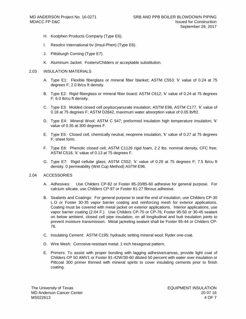
H. Koolphen Products Company (Type E6).
I. Resolco International bv (Insul-Phen) (Type E6).
J. Pittsburgh Corning (Type E7).
K. Aluminum Jacket: Fosters/Childers or acceptable substitution.
2.03 INSULATION MATERIALS
A. Type E1: Flexible fiberglass or mineral fiber blanket; ASTM C553; 'k' value of 0.24 at 75 degrees F; 2.0 lb/cu ft density.
B. Type E2: Rigid fiberglass or mineral fiber board; ASTM C612; 'k' value of 0.24 at 75 degrees F; 6.0 lb/cu ft density.
C. Type E3: Molded closed cell poyisocyanurate insulation; ASTM E96, ASTM C177, 'k' value of 0.18 at 75 degrees F; ASTM D2842, maximum water absorption value of 0.05 lb/ft2.
D. Type E4: Mineral Wool; ASTM C 547; preformed insulation high temperature insulation; 'k' value of 0.35 at 300 degrees F.
E. Type E5: Closed cell, chemically neutral, neoprene insulation, 'k' value of 0.27 at 75 degrees F; sheet form.
F. Type E6: Phenolic closed cell, ASTM C1126 rigid foam, 2.2 lbs. nominal density, CFC free; ASTM C518, 'k' value of 0.13 at 75 degrees F.
G. Type E7: Rigid cellular glass; ASTM C552; ‘k’ value of 0.29 at 75 degrees F; 7.5 lb/cu ft density. 0 permeability (Wet Cup Method) ASTM E96.
2.04 ACCESSORIES
A. Adhesives: Use Childers CP-82 or Foster 85-20/85-60 adhesive for general purpose. For calcium silicate, use Childers CP-97 or Foster 81-27 fibrous adhesive.
B. Sealants and Coatings: For general purpose to seal the end of insulation, use Childers CP-30 L.O or Foster 30-35 vapor barrier coating and reinforcing mesh for exterior applications. Coating must be covered with metal jacket on exterior applications. Interior applications, use vapor barrier coating (2.04 F.) Use Childers CP-70 or CP-76; Foster 95-50 or 30-45 sealant on below ambient, closed cell pipe insulation, on all longitudinal and butt insulation joints to prevent moisture transmission. Metal jacketing sealant shall be Foster 95-44 or Childers CP-76.
C. Insulating Cement: ASTM C195; hydraulic setting mineral wool; Ryder one-coat.
D. Wire Mesh: Corrosive-resistant metal; 1 inch hexagonal pattern.
E. Primers: To assist with proper bonding with lagging adhesive/canvas, provide light coat of Childers CP 50 AMV1 or Foster 81-42W/30-60 diluted 50 percent with water over insulation or Pittcoat 300 primer thinned with mineral spirits to cover insulating cements prior to finish coating.
MD ANDERSON Project No. 16-0271 SRB AND PPB BOILER BLOWDOWN PIPING MDACC FP D&C Issued for Construction September 28, 2017
The University of Texas EQUIPMENT INSULATION MD Anderson Cancer Center 20 07 16 MS022613 5 OF 7
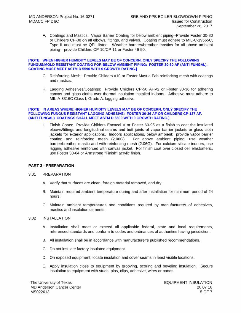
F. Coatings and Mastics: Vapor Barrier Coating for below ambient piping--Provide Foster 30-80 or Childers CP-38 on all elbows, fittings, and valves. Coating must adhere to MIL-C-19565C, Type II and must be QPL listed. Weather barriers/breather mastics for all above ambient piping—provide Childers CP-10/CP-11 or Foster 46-50.
[NOTE: WHEN HIGHER HUMIDITY LEVELS MAY BE OF CONCERN, ONLY SPECIFY THE FOLLOWING FUNGUS/MOLD RESISTANT COATING FOR BELOW AMBIENT PIPING: FOSTER 30-80 AF (ANTI FUNGAL). COATING MUST MEET ASTM D 5590 WITH 0 GROWTH RATING.]
G. Reinforcing Mesh: Provide Childers #10 or Foster Mast a Fab reinforicng mesh with coatings and mastics.
H. Lagging Adhesives/Coatings: Provide Childers CP-50 AHV2 or Foster 30-36 for adhering canvas and glass cloths over thermal insulation installed indoors. Adhesive must adhere to MIL-A-3316C Class I, Grade A. lagging adhesive.
[NOTE: IN AREAS WHERE HIGHER HUMIDITY LEVELS MAY BE OF CONCERN, ONLY SPECIFY THE FOLLOWING FUNGUS RESISTANT LAGGING ADHESIVE: FOSTER 30-36 AF OR CHILDERS CP-137 AF. (ANTI FUNGAL) COATINGS SHALL MEET ASTM D 5590 WITH 0 GROWTH RATING.]
I. Finish Coats: Provide Childers Encacel V or Foster 60-95 as a finish to coat the insulated elbows/fittings and longitudinal seams and butt joints of vapor barrier jackets or glass cloth jackets for exterior applications. Indoors applications, below ambient: provide vapor barrier coating and reinforcing mesh (2.06G). For above ambient piping, use weather barrier/breather mastic and with reinforcing mesh (2.06G). For calcium silicate indoors, use lagging adhesive reinforced with canvas jacket. For finish coat over closed cell elastomeric, use Foster 30-64 or Armstrong "Finish" acrylic finish.
PART 3 - PREPARATION
3.01 PREPARATION
A. Verify that surfaces are clean, foreign material removed, and dry.
B. Maintain required ambient temperature during and after installation for minimum period of 24 hours.
C. Maintain ambient temperatures and conditions required by manufacturers of adhesives, mastics and insulation cements.
3.02 INSTALLATION
A. Installation shall meet or exceed all applicable federal, state and local requirements, referenced standards and conform to codes and ordinances of authorities having jurisdiction.
B. All installation shall be in accordance with manufacturer’s published recommendations.
C. Do not insulate factory insulated equipment.
D. On exposed equipment, locate insulation and cover seams in least visible locations.
E. Apply insulation close to equipment by grooving, scoring and beveling insulation. Secure insulation to equipment with studs, pins, clips, adhesive, wires or bands.
MD ANDERSON Project No. 16-0271 SRB AND PPB BOILER BLOWDOWN PIPING MDACC FP D&C Issued for Construction September 28, 2017
The University of Texas EQUIPMENT INSULATION MD Anderson Cancer Center 20 07 16 MS022613 6 OF 7
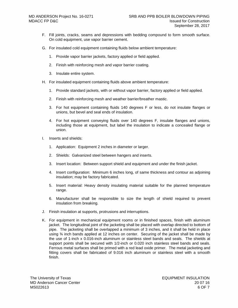
F. Fill joints, cracks, seams and depressions with bedding compound to form smooth surface. On cold equipment, use vapor barrier cement.
G. For insulated cold equipment containing fluids below ambient temperature:
1. Provide vapor barrier jackets, factory applied or field applied.
2. Finish with reinforcing mesh and vapor barrier coating.
3. Insulate entire system.
H. For insulated equipment containing fluids above ambient temperature:
1. Provide standard jackets, with or without vapor barrier, factory applied or field applied.
2. Finish with reinforcing mesh and weather barrier/breather mastic.
3. For hot equipment containing fluids 140 degrees F or less, do not insulate flanges or unions, but bevel and seal ends of insulation.
4. For hot equipment conveying fluids over 140 degrees F, insulate flanges and unions, including those at equipment, but label the insulation to indicate a concealed flange or union.
I. Inserts and shields:
1. Application: Equipment 2 inches in diameter or larger.
2. Shields: Galvanized steel between hangers and inserts.
3. Insert location: Between support shield and equipment and under the finish jacket.
4. Insert configuration: Minimum 6 inches long, of same thickness and contour as adjoining insulation; may be factory fabricated.
5. Insert material: Heavy density insulating material suitable for the planned temperature range.
6. Manufacturer shall be responsible to size the length of shield required to prevent insulation from breaking.
J. Finish insulation at supports, protrusions and interruptions.
K. For equipment in mechanical equipment rooms or in finished spaces, finish with aluminum jacket. The longitudinal joint of the jacketing shall be placed with overlap directed to bottom of pipe. The jacketing shall be overlapped a minimum of 3 inches, and it shall be held in place using ¾ inch bands applied at 12 inches on center. Securing of the jacket shall be made by the use of 1-inch x 0.016-inch aluminum or stainless steel bands and seals. The shields at support points shall be secured with 1/2-inch or 0.020 inch stainless steel bands and seals. Ferrous metal surfaces shall be primed with a red lead oxide primer. The metal jacketing and fitting covers shall be fabricated of 9.016 inch aluminum or stainless steel with a smooth finish.
MD ANDERSON Project No. 16-0271 SRB AND PPB BOILER BLOWDOWN PIPING MDACC FP D&C Issued for Construction September 28, 2017
The University of Texas EQUIPMENT INSULATION MD Anderson Cancer Center 20 07 16 MS022613 7 OF 7
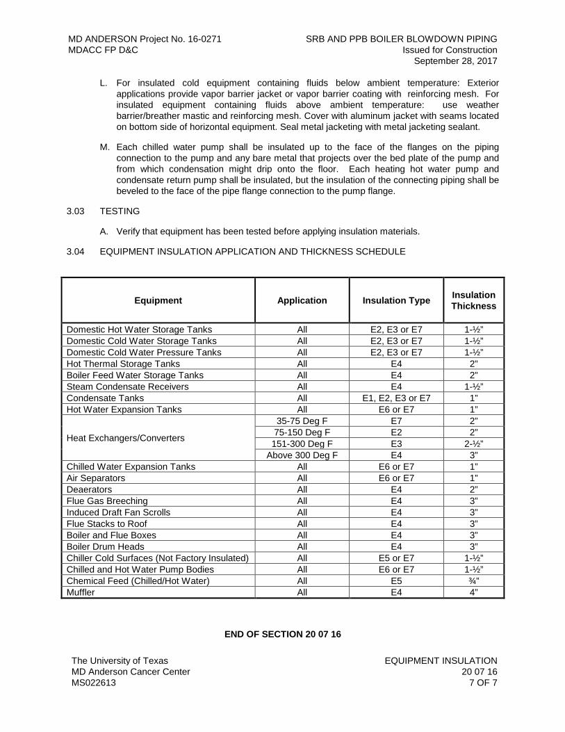
L. For insulated cold equipment containing fluids below ambient temperature: Exterior applications provide vapor barrier jacket or vapor barrier coating with reinforcing mesh. For insulated equipment containing fluids above ambient temperature: use weather barrier/breather mastic and reinforcing mesh. Cover with aluminum jacket with seams located on bottom side of horizontal equipment. Seal metal jacketing with metal jacketing sealant.
M. Each chilled water pump shall be insulated up to the face of the flanges on the piping connection to the pump and any bare metal that projects over the bed plate of the pump and from which condensation might drip onto the floor. Each heating hot water pump and condensate return pump shall be insulated, but the insulation of the connecting piping shall be beveled to the face of the pipe flange connection to the pump flange.
3.03 TESTING
A. Verify that equipment has been tested before applying insulation materials.
3.04 EQUIPMENT INSULATION APPLICATION AND THICKNESS SCHEDULE
Equipment
Application
Insulation Type
Insulation Thickness
Domestic Hot Water Storage Tanks All E2, E3 or E7 1-½” Domestic Cold Water Storage Tanks All E2, E3 or E7 1-½” Domestic Cold Water Pressure Tanks All E2, E3 or E7 1-½” Hot Thermal Storage Tanks All E4 2” Boiler Feed Water Storage Tanks All E4 2” Steam Condensate Receivers All E4 1-½” Condensate Tanks All E1, E2, E3 or E7 1” Hot Water Expansion Tanks All E6 or E7 1”
Heat Exchangers/Converters
35-75 Deg F E7 2” 75-150 Deg F E2 2” 151-300 Deg F E3 2-½”
Above 300 Deg F E4 3” Chilled Water Expansion Tanks All E6 or E7 1” Air Separators All E6 or E7 1” Deaerators All E4 2” Flue Gas Breeching All E4 3” Induced Draft Fan Scrolls All E4 3” Flue Stacks to Roof All E4 3” Boiler and Flue Boxes All E4 3” Boiler Drum Heads All E4 3” Chiller Cold Surfaces (Not Factory Insulated) All E5 or E7 1-½” Chilled and Hot Water Pump Bodies All E6 or E7 1-½” Chemical Feed (Chilled/Hot Water) All E5 ¾” Muffler All E4 4”
END OF SECTION 20 07 16
MD ANDERSON Project No. 16-0271 SRB AND PPB BOILER BLOWDOWN PIPING MDACC FP D&C Issued for Construction September 28, 2017
The University of Texas PIPING INSULATION MD Anderson Cancer Center 20 07 19 MS022613 1 OF 15
SECTION 20 07 19 – PIPING INSULATION
PART 1 - GENERAL
1.01 RELATED DOCUMENTS
A. Drawings and general provisions of the Contract, including General Conditions and Division 01 Specification Sections, apply to this Section.
B. Specifications throughout all Divisions of the Project Manual are directly applicable to this Section, and this Section is directly applicable to them.
1.02 SUMMARY
A. Perform all Work required to provide and install piping insulation, jackets and accessories indicated by the Contract Documents with supplementary items necessary for proper installation.
1.03 REFERENCE STANDARDS
A. The latest published edition of a reference shall be applicable to this Project unless identified by a specific edition date.
B. All reference amendments adopted prior to the effective date of this Contract shall be applicable to this Project.
C. All materials, installation and Workmanship shall comply with the applicable requirements and standards addressed within the following references:
1. ASTM B209 - Aluminum and Aluminum-Alloy Sheet and Plate.
2. ASTM C168 - Terminology Relating to Thermal Insulation Materials.
3. ASTM C177 - Steady-State Heat Flux Measurements and Thermal Transmission Properties by Means of the Guarded- Hot-Plate Apparatus.
4. ASTM C195 - Mineral Fiber Thermal Insulating Cement.
5. ASTM C335 - Steady-State Heat Transfer Properties of Horizontal Pipe Insulation.
6. ASTM C449 - Mineral Fiber Hydraulic-Setting Thermal Insulating and Finishing Cement.
7. ASTM C518 - Steady-State Thermal Transmission Properties by Means of the Heat Flow Meter Apparatus.
8. ASTM C534 - Preformed Flexible Elastomeric Cellular Thermal Insulation in Sheet and Tubular Form.
9. ASTM C547 - Mineral Fiber Pipe Insulation.
10. ASTM C552 - Cellular Glass Thermal Insulation.
11. ASTM C578 - Rigid, Cellular Polystyrene Thermal Insulation.
MD ANDERSON Project No. 16-0271 SRB AND PPB BOILER BLOWDOWN PIPING MDACC FP D&C Issued for Construction September 28, 2017
The University of Texas PIPING INSULATION MD Anderson Cancer Center 20 07 19 MS022613 2 OF 15
12. ASTM C585 - Inner and Outer Diameters of Rigid Thermal Insulation for Nominal Sizes of Pipe and Tubing (NPS System).
13. ASTM C591 - Unfaced Preformed Rigid Cellular Polyisocyanurate Thermal Insulation.
14. ASTM C610 - Molded Expanded Perlite Block and Pipe Thermal Insulation.
15. ASTM C921 - Jackets for Thermal Insulation.
16. ASTM C1126 - Faced or Unfaced Rigid Celluar Phenolic Thermal Insulation.
17. ASTM D1056 - Flexible Cellular Materials - Sponge or Expanded Rubber.
18. ASTM D1667 - Flexible Cellular Materials - Vinyl Chloride Polymers and Copolymers (Closed Cell Foam).
19. ASTM D2842 - Water Absorption of Rigid Cellular Plastics.
20. ASTM C795 - Insulation For Use Over Austenitic Steel.
21. ASTM E84 - Surface Burning Characteristics of Building Materials.
22. ASTM E96 - Water Vapor Transmission of Materials.
23. NFPA 255 - Surface Burning Characteristics of Building Materials.
24. UL 723 - Surface Burning Characteristics of Building Materials.
25. ASTM D5590 - Standard Test Method for Determining the Resistance of Paint Films and Related Coatings to Fungal Defacement by Accelerated Four-Week Agar Plate Assay
1.04 DEFINITIONS
A. Concealed: Areas that cannot be seen by the building occupants.
B. Interior Exposed: Areas that are exposed to view by the building occupants, including underneath countertops, inside cabinets and closets, and all equipment rooms.
C. Interior: Areas inside the building exterior envelope that are not exposed to the outdoors.
D. Exterior: Areas outside the building exterior envelope that are exposed to the outdoors, including building crawl spaces and loading dock areas.
1.05 QUALITY ASSURANCE
A. All piping requiring insulation shall be insulated as specified herein and as required for a complete system. In each case, the insulation shall be equivalent to that specified and materials applied and finished as described in these Specifications.
B. All insulation, jacket, adhesives, mastics, sealers, etc., utilized in the fabrication of these systems shall meet NFPA for fire resistant ratings (maximum of 25 flame spread and 50 smoke developed ratings) and shall be approved by the insulation manufacturer for guaranteed performances when incorporated into their insulation system, unless a specific product is specified for a specific application and is stated as an exception to this requirement.
MD ANDERSON Project No. 16-0271 SRB AND PPB BOILER BLOWDOWN PIPING MDACC FP D&C Issued for Construction September 28, 2017
The University of Texas PIPING INSULATION MD Anderson Cancer Center 20 07 19 MS022613 3 OF 15
1. Certificates to this effect shall be submitted along with Contractor’s submittal data for this Section of the Specifications.
2. No material shall be used that, when tested by the ASTM E84-89 test method, is found to melt, drip or delaminate to such a degree that the continuity of the flame front is destroyed, thereby resulting in an artificially low flame spread rating.
C. Application Company Qualifications: Company performing the Work of this Section shall have minimum three (3) years experience specializing in the trade.
D. All insulation shall be applied by mechanics skilled in this particular Work and regularly engaged in such occupation.
E. All insulation shall be applied in strict accordance with these Specifications and with factory printed recommendations on items not herein mentioned. Unsightly, inadequate, or sloppy Work will not be acceptable.
1.06 SUBMITTALS
A. Product Data:
1. Provide product description, list of materials, “k” value, “R” value, mean temperature range, and thickness for each service and location.
2. Samples: When requested, submit three (3) samples of any representative size illustrating each insulation type
B. Operation and Maintenance Data:
1. Indicate procedures that ensure acceptable standards will be achieved. Submit certificates to this effect.
1.07 DELIVERY, STORAGE AND HANDLING
A. Deliver materials to the Project Site in original factory packaging, labeled with manufacturer’s identification including product thermal ratings and thickness.
B. Store insulation in original wrapping and protect from weather and construction traffic. Protect insulation against dirt, water, chemical, and mechanical damage.
C. Maintain ambient temperatures and conditions required by manufacturers of adhesives, mastics and insulation cements.
PART 2 - PRODUCTS
2.01 GENERAL
A. All materials shall meet or exceed all applicable referenced standards, federal, state and local requirements, and conform to codes and ordinances of authorities having jurisdiction.
2.02 MANUFACTURERS
A. Insulation:
MD ANDERSON Project No. 16-0271 SRB AND PPB BOILER BLOWDOWN PIPING MDACC FP D&C Issued for Construction September 28, 2017
The University of Texas PIPING INSULATION MD Anderson Cancer Center 20 07 19 MS022613 4 OF 15
1. Owens-Corning (Type P1).
2. Certainteed Corporation (Type P1).
3. Johns Manville Corporation (Type P1).
4. Knauf Corporation (Type P1).
5. Dow Chemical Company (Type P2).
6. Armstrong/Armacell (Armaflex) (Type P3).
7. RBX Industries/Rubatex (Type P3).
8. Industrial Insulation Group, LLC (Type P4).
9. Resolco International by (Insul-Phen) (Type P5).
10. FOAMGLAS (Cellular Glass) by Pittsburgh Corning (Type P6).
B. Jackets:
1. Childers Products Company
2. PABCO
3. RPR Products, Inc.
4. Venture Clad Corporation
5. Foster Vapor Fas 62-05
6. Foamglas
C. Coatings, Sealants, and Adhesives:
1. Foster
2. Childers
2.03 INSULATION
A. Type P1: Fiberglass preformed insulation; ASTM C 547; minimum 3.0 lb/cu ft density, ASTM C335,'k' value of 0.23 at 75 degrees F; noncombustible.
B. Type P2: Molded closed cell polyisocyanurate insulation; ASTM E96, maximum water vapor transmission rating of 0.005 Perm-In; ASTM C518, 'k' value of 0.20 at 75 degrees F; ASTM D2842, water absorption value of 0.05 lb/ft2.
C. Type P3: Closed cell elastomeric, flexible, insulation; ASTM E96; maximum vapor transmission rating of 0.20 perms; ASTM C 518; 'k' value of 0.27 at 75 degrees F.
D. Type P4: Mineral Wool; ASTM C 547; preformed, high temperature insulation; 'k' value of 0.35 at 300 degrees F.
MD ANDERSON Project No. 16-0271 SRB AND PPB BOILER BLOWDOWN PIPING MDACC FP D&C Issued for Construction September 28, 2017
The University of Texas PIPING INSULATION MD Anderson Cancer Center 20 07 19 MS022613 5 OF 15
E. Type P5: Phenolic closed cell, ASTM C1126 rigid foam, 2.2 lbs. nominal density, CFC free; ASTM C518, 'k' value of 0.13 at 75 degrees F. (Note material thickness limit is 3 inches as tested in accordance with ASTM E84).
F. Type P5A: Phenolic closed cell insulation; ASTM E96, maximum water vapor transmission rating of 0.02 Perm-In; ASTM C1126 rigid foam, 3.75 lbs. nominal density, CFC free; ASTM C518, 'k' value of 0.16 at 75 degrees F. (Note material thickness limit is 3 inches as tested in accordance with ASTM E84).
G. Type P5B: Phenolic closed cell insulation; ASTM E96, maximum water vapor transmission rating of 0.02 Perm-In; ASTM C1126 rigid foam, 5.0 lbs. nominal density, CFC free; ASTM C518, ‘k’ value of 0.21 at 75 degrees F. (Note material thickness limit is 3 inches as tested in accordance with ASTM E84).
H. Type P6: Cellular Glass, ASTM C552, 7.5 lbs./cu.ft, density, ASTM E96 (Wet Cup Method) 0.00 water vapor perm , ASTM C518 ‘k’ value of 0.29 at 75 degrees F.
2.04 JACKETS
A. Factory Applied Jackets:
1. White kraft bonded to reinforced foil vapor barrier with self-sealing adhesive joints.
2. ASJ White, triple-ply laminate polypropylene, mold resistant, metalized polyester vapor barrier film backing: Venture 1555U or Insulrap 30 Vapor Barrier I-30.
B. Field Applied Jackets:
1. PVC Jackets: UL listed 25/50 rated per ASTM E 84, UV resistant, minimum insulation thickness 0.020 inches for pipe outside diameters up to 18 inches and 0.030 inches for pipe outside diameters 18 inches and above. Standard manufactured PVC cover fittings cover system consisting of one-piece, pre-molded, PVC covers with fiberglass inserts manufactured from 20-mils thick, high-impact, ultraviolet-resistant. Use ultraviolet resistant adhesive as recommended by the manufacturer.
2. Reinforcing Mesh: Glass Fiber Childers Chil-Glas #10 or synthetic 9X8 mesh with minimum weight of 0.9 ounces per square yard.
3. Aluminum Jackets: ASTM B 209; 0.020 inch thick; smooth finish with factory applied moisture barrier.
4. Stainless Steel Jackets: Type 304 stainless steel; 0.010 inch thick; smooth finish.
5. VentureClad 1577CW or Foster Vapor Fas 62-05, zero permeability and mold resistant jacket material, 5-ply laminate with 5-6 mil film with adhesive on one side. Jacketing laminated film must have UV coating for additional exterior protection. Product shall be used with phenolic closed cell insulation where Type 5A and 5B insulation is installed on existing chilled water piping being repaired or being modified.
2.05 COATINGS, SEALANTS, AND ADHESIVES
A. Insulating Cement: ASTM C 195; hydraulic setting mineral wool; Ryder One-Coat.
B. Sealants: Foster 95-50; Childers CP-70 or CP-76
MD ANDERSON Project No. 16-0271 SRB AND PPB BOILER BLOWDOWN PIPING MDACC FP D&C Issued for Construction September 28, 2017
The University of Texas PIPING INSULATION MD Anderson Cancer Center 20 07 19 MS022613 6 OF 15
1. Apply at valves, fittings and where insulation is terminated. Brush-apply sealant to end of insulation and continue along pipe surface.
2. Below-ambient closed cell pipe insulation (Type P5, P5A, P5B): apply sealant on all longitudinal and butt insulation joints to prevent moisture transmission.
C. Adhesives: Use to adhere the longitudinal lap seam of vapor barrier jackets and at butt joints between insulation or fitting covers. Provide Childers CP-82 or Foster 85-20/85-60 as general purpose adhesive. For use with calcium silicate or expanded perlite insulation, use Childers CP-97 or Foster 81-27 fibrous adhesive when adhering pipe saddles and shields to the insulation.
D. Primers: For proper bonding with lagging adhesive/canvas provide light coat of Childers CP-50 AMV1 or Foster 30-36 diluted 50 percent with water over insulation or Pittcoat 300 primer thinned with mineral spirits to cover insulating cements prior to finish coating.
E. Coatings and Mastics:
1. Vapor barrier coating for indoor, below-ambient applications: Foster 30-80 or Childers CP-38 on all elbows, fittings, and valves. Coating shall adhere to MIL-C-19565C, Type II and shall be QPL listed.
2. Weather barrier/breather mastics for above-ambient piping applications: Childers CP-10/CP-11 or Foster 46-50.
3. High humidity applications: Foster 30-80 AF or Childers CP-137 AF fungus/mold resistant coating that meets ASTM D 5590 with zero growth rating.
4. Exterior applications: Childers CP 30LO (must be covered by metal jacketing), Childers CP-45 Encacel V, or Foster 60-95 Monolar for insulated elbows/fittings, longitudinal seams, and butt joints of vapor barrier jackets or glass cloth jackets.
5. Finish coat over closed cell elastomeric: Foster 30-64 or Armstrong "Finish" acrylic finish.
6. Canvas Finishes:
a. Apply lagging adhesive to prevent mildew for securing canvas. Apply anti-fungal lagging adhesive that adheres to ASTM D 5590 with zero growth rating. (Foster 30-36AF, Childers CP-137AF) Do not use wheat paste.
b. Exterior Applications: cover all canvas insulation with a fire-retardant weather barrier mastic. On canvas jacketed systems where seam joints at fittings are rough, cover with an application of insulating cement and smooth with a trowel before the canvas is applied with adhesive. Canvas shall be free of wrinkles and have a smooth, neat appearance.
F. Reinforcing Mesh: Childers Chil-Glas #10 or Foster Mast-a-Fab 9x8 reinforcing mesh with coatings and mastics.
G. Lagging Adhesives/Coatings: Childers CP-50A HV2 or Foster 30-36 for adhering canvas and glass cloths over thermal insulation installed indoors. Adhesive shall adhere to MIL-A-3316C Class I, Grade A.
MD ANDERSON Project No. 16-0271 SRB AND PPB BOILER BLOWDOWN PIPING MDACC FP D&C Issued for Construction September 28, 2017
The University of Texas PIPING INSULATION MD Anderson Cancer Center 20 07 19 MS022613 7 OF 15
a. High humidity applications (unconditioned space): Foster 30-36 AF or Childers CP-137 AF fungus/mold resistant coating that meets ASTM D 5590 with zero growth rating. Coating shall adhere to MIL-C-19565C, Type II and must be QPL listed.
2.06 APPLICATIONS
A. Interior Concealed Applications (Plenums, Chases):
1. Type P1 Insulation: Provide factory applied ASJ white kraft foil vapor barrier.
a. Below-ambient piping: Coat all ASJ seams with Foster 30-80 or Childers CP-38 vapor barrier coating. Coat all elbows, fittings, and valves with same vapor barrier coating and Foster Mast-a-Fab or Childers Chil-Glas #10 reinforcing mesh.
b. High humidity applications: Foster 30-36 AF.
2. Type P3 Insulation: Finish coat is not required.
3. Type P4 Insulation: Lightly coat insulation with lagging adhesive diluted 50% with water for proper bonding with canvas/lagging adhesive. Cover with a canvas jacket and non-diluted Childers CP-50A HV2 or Foster 30-36 lagging adhesive.
a. High humidity applications (unconditioned space): Foster 30-36 AF or Childers CP-137 AF fungus/mold resistant coating.
4. Type P5 and P5A, 5B Insulation: VentureClad jacket on piping where condensation can occur or where installed on existing chilled water piping, chilled water condensate drain piping, and roof storm drain piping that transports cold rain water from the building roof.
5. Type P5 Jacket not required when insulation is used on hot water piping.
6. Type P6 Insulation:
a. Above-ambient piping: Pittcoat 404, Foster 46-50, or Childers CP-10/11 pre-molded PVC covers per manufacturer’s recommendations. Jacket is not required when this type of piping insulation is concealed within a piping chase.
b. Below-ambient piping: Coat all ASJ seams with Foster 30-80 or Childers CP-38 vapor barrier coating. Coat all elbows, fittings, and valves with same vapor barrier coating and Foster Mast-a-Fab or Childers Chil-Glas #10 reinforcing mesh.
c. High humidity applications (unconditioned space): Foster 30-36 AF or Childers CP-137 AF fungus/mold resistant coating.
B. Interior Exposed Applications (Equipment Rooms):
1. Type P1 and P2 Insulation: Factory applied ASJ white kraft foil vapor barrier. Finish with canvas jacket or Childers Chil-Glas #10 glass membrane with Childers CP-50A HV2 or Foster 30-36. Verify jacket is suitable for applications.
a. High humidity applications (unconditioned space): Foster 30-36 AF or Childers CP-137 AF fungus/mold resistant coating. Finish coat is not required.
2. Type P3 Insulation: Finish coat is not required.
MD ANDERSON Project No. 16-0271 SRB AND PPB BOILER BLOWDOWN PIPING MDACC FP D&C Issued for Construction September 28, 2017
The University of Texas PIPING INSULATION MD Anderson Cancer Center 20 07 19 MS022613 8 OF 15
3. Type P4 Insulation: Lightly coat insulation with lagging adhesive diluted 50% with water for proper bonding with canvas/lagging adhesive. Cover with a canvas jacket and non-diluted Childers CP-50A HV2 or Foster 30-60 lagging adhesive.
a. High humidity applications (unconditioned space): Foster 30-36 AF or Childers CP-137 AF fungus/mold resistant coating. Finish coat is not required.
4. Type P5 Insulation: Factory applied ASJ white kraft foil vapor barrier.
5. Type P5 and P5A Insulation: VentureClad jacket on piping where condensation can occur or where installed on existing chilled water piping, chilled water condensate drain piping, and roof storm drain piping that transports cold rain water from the building roof.
6. Type P6 Insulation: Provide triple-ply laminate polypropylene, mold resistant with a metal foil and polyester vapor barrier film backing.
a. Below-ambient piping: Coat all ASJ seams with Foster 30-80 or Childers CP-38 vapor barrier coating. Coat all elbows, fittings, and valves with same vapor barrier coating and Foster Mast-a-Fab or Childers Chil-Glas #10 reinforcing mesh.
b. Above-ambient piping: Provide Pittcoat 404, Foster 46-50, or Childers CP-10/11 or pre-molded PVC covers per manufacturer’s recommendations.
c. High humidity applications (unconditioned space): Foster 30-36 AF or Childers CP-137 AF fungus/mold resistant coating.
7. All exposed insulated piping within six (6) feet of the floor shall be protected with aluminum or stainless steel jacket to protect insulation from being torn or punctured.
C. Exterior Applications:
1. Insulate piping system as indicated under Interior Exposed Applications, prior to final jacket installation.
2. Provide electric heat tracing for all exterior small bore piping 2 inches and smaller where water may be susceptible to freezing due to intermittent flow conditions.
[ EDITOR’S NOTE: ENGINEER SHALL INDICATE LOCATION OF HEAT TRACING ON PIPING PLANS AND ELECTRICAL REQUIREMENTS ON ELECTRICAL DRAWINGS ]
3. Final jacket cover shall be aluminum or stainless steel having integral moisture barrier with seams located at 2 or 10 o'clock position of horizontal piping. All laps shall be minimum 2 inches. Apply Foster 95-44 or Childers CP-76 metal jacketing sealant on all laps to prevent water transmission.
4. Type P1 Insulation: For above-ambient piping, finish with Childers Chil-Glas #10 or 9X8 reinforcing mesh and Childers CP-10/CP-11, or Foster 46-50 weather barrier/breather mastic, prior to final jacket installation.
5. P6 Insulation Above-ground: Provide (50 mil thickness) self-sealing non- metallic, bituminous compound reinforced with glass fiber membrane with 1 mil aluminum top film jacketing for both chilled water and hot water piping (PITTWRAP CW Plus). Provide metal jacketi where material is exposed to ultraviolet rays.
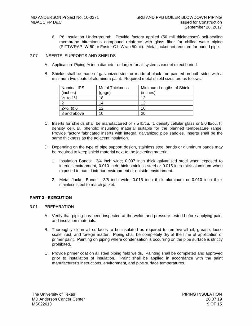
MD ANDERSON Project No. 16-0271 SRB AND PPB BOILER BLOWDOWN PIPING MDACC FP D&C Issued for Construction September 28, 2017
The University of Texas PIPING INSULATION MD Anderson Cancer Center 20 07 19 MS022613 9 OF 15
6. P6 Insulation Underground: Provide factory applied (50 mil thicknesses) self-sealing membrane bituminous compound reinforce with glass fiber for chilled water piping (PITTWRAP IW 50 or Foster C.I. Wrap 50mil). Metal jacket not required for buried pipe.
2.07 INSERTS, SUPPORTS AND SHIELDS
A. Application: Piping ½ inch diameter or larger for all systems except direct buried.
B. Shields shall be made of galvanized steel or made of black iron painted on both sides with a minimum two coats of aluminum paint. Required metal shield sizes are as follows:
Nominal IPS (inches)
Metal Thickness (gage)
Minimum Lengths of Shield (inches)
½ to 1½ 18 12 2 14 12 2-½ to 6 12 16 8 and above 10 20
C. Inserts for shields shall be manufactured of 7.5 lb/cu. ft. density cellular glass or 5.0 lb/cu. ft.
density cellular, phenolic insulating material suitable for the planned temperature range. Provide factory fabricated inserts with integral galvanized pipe saddles. Inserts shall be the same thickness as the adjacent insulation.
D. Depending on the type of pipe support design, stainless steel bands or aluminum bands may be required to keep shield material next to the jacketing material.
1. Insulation Bands: 3/4 inch wide; 0.007 inch thick galvanized steel when exposed to interior environment, 0.010 inch thick stainless steel or 0.015 inch thick aluminum when exposed to humid interior environment or outside environment.
2. Metal Jacket Bands: 3/8 inch wide; 0.015 inch thick aluminum or 0.010 inch thick stainless steel to match jacket.
PART 3 - EXECUTION
3.01 PREPARATION
A. Verify that piping has been inspected at the welds and pressure tested before applying paint and insulation materials.
B. Thoroughly clean all surfaces to be insulated as required to remove all oil, grease, loose scale, rust, and foreign matter. Piping shall be completely dry at the time of application of primer paint. Painting on piping where condensation is occurring on the pipe surface is strictly prohibited.
C. Provide primer coat on all steel piping field welds. Painting shall be completed and approved prior to installation of insulation. Paint shall be applied in accordance with the paint manufacturer’s instructions, environment, and pipe surface temperatures.
MD ANDERSON Project No. 16-0271 SRB AND PPB BOILER BLOWDOWN PIPING MDACC FP D&C Issued for Construction September 28, 2017
The University of Texas PIPING INSULATION MD Anderson Cancer Center 20 07 19 MS022613 10 OF 15
3.02 INSTALLATION
A. Installation shall meet or exceed all applicable federal, state and local requirements, referenced standards and conform to codes and ordinances of authorities having jurisdiction.
B. Installation of insulation and jacket materials shall be in accordance with manufacturer’s published instructions.
C. Handle and install materials in accordance with manufacturer’s instructions in the absence of specific instructions herein.
D. On exposed piping, locate insulation cover seams with the ridge of the lap joint is directed down.
E. Exposed Insulated piping within six feet of the floor shall be protected with an aluminum or stainless jacket material to protect the insulation.
F. Insulate fittings, joints and valves with molded insulation of the same material and thickness as adjoining pipe. Open voids and cracks insulation shall be kept at a minimum when placing insulation on abnormal or irregular shapes. Use closed cell or recommended fill material as instructed by the insulation manufacturer to close openings. Fiberglass insulation shall not be used as a fill material on chilled water piping or fittings. Vapor seal all cold piping ASJ seams and elbows/fittings with vapor barrier coating and reinforcing mesh.
G. Continue insulation through walls, sleeves, pipe hangers, floors, and other pipe penetrations.
H. Provide dams in insulation at intervals not to exceed 20 feet on cold piping systems to prevent migration of condensation or fluid leaks. Indicate visually where the dams are located for maintenance personnel to identify and also provide dams at butt joints of insulation at fittings, flanges, valves, and hangers.
I. Insulate entire system including fittings, valves, flanges and strainers. Use closed cell insulation on cold piping system flexible connections, expansion joints and unions, bevel and seal ends of insulation and continue sealant or coating a minimum of 4 inches along the piping, unless stated otherwise. On all closed-cell insulation, cold piping, use insulation joint sealant on all longitudinal and butt joints.
J. For hot piping conveying fluids 180 degrees F or less, do not insulate flanges and unions at equipment, but bevel and seal ends of insulation. Continue sealant or coating a minimum of 4 inches along the piping.
K. On heating piping systems conveying fluids over 180 degrees F with unions, flanges, valves, strainers and equipment that are anticipated to be removed for maintenance, the insulation shall terminate (beveled to pipe) just prior to the flange or union with vapor barrier sealed to pipe. The tapered segment of insulation shall not interfere with the removal of unions flange bolts or equipment. The unions, flanges, valves and strainers shall be insulated with removable insulated covers with toggle catches or Velcro straps
L. All sections of molded pipe covering shall be firmly butted together. Where an insulation covering is applied, it shall lap the adjoining section of insulation by at least three inches (3 inches). Where insulation terminates, it shall be neatly beveled and finished. All materials used shall be fire retardant or nonflammable.
MD ANDERSON Project No. 16-0271 SRB AND PPB BOILER BLOWDOWN PIPING MDACC FP D&C Issued for Construction September 28, 2017
The University of Texas PIPING INSULATION MD Anderson Cancer Center 20 07 19 MS022613 11 OF 15
M. Where vapor barriers are required, the vapor barrier shall be on the outside. Extreme care shall be taken that the vapor barrier is unbroken. Joints, etc., shall be sealed with vapor barrier coating. Where insulation with a vapor barrier terminates, seal off with vapor barrier continuous to the surface being insulated. Ends shall not be left raw.
N. Where pipe chases are tight, adequate provision shall be made at the rough-in stage using offset fittings or other means (except springing the pipe) to ensure that insulation can be applied throughout the length of the pipe.
O. When installing phenolic insulation provide a 5 lb. density insert of same thickness and contour as adjoining 3.75 lb. density insulation, between the support shield and piping, and under the finish jacket, on piping 1½ inch diameter or larger, to prevent insulation from sagging at support points. Provide inserts for 180-degree arc and not less than 2 inches more than the length of the pipe support shield or minimum 12 inches long (whichever is greater). Pipe support shield shall be adhered to insulation with a UL approved adhesive that meets E-84 requirements.
P. Seal all insulation at supports, protrusions and interruptions. Maintain vapor barrier with finish coat.
Q. Shields:
1. Install between pipe hangers or pipe hanger rolls and inserts. Curved metal shields shall be used between the hangers or support points and at the bottom of insulated pipe.
2. Hangers shall support the load of the insulated pipe section on the outside of the insulation and shall not be in direct contact with the pipe.
3. Manufacturer shall be responsible to size the length of shield required to prevent insulation from breaking.
4. Provide rigid insulation at each support point, a minimum of 2 inches longer than shield length.
5. Curved metal shields shall be designed to limit the bearing stress on the insulation to 35 psi and shall be curved to fit up to mid-perimeter of the insulated pipe.
3.03 EXISTING CHILLED WATER PIPING INSULATED WITH PHENOLIC FOAM INSULATION
A. Re-insulate existing piping systems after repairs have been performed in the same manner as the original installation unless:
1. The nature of damage to the insulation indicates that the system was not insulated properly, and that installation of flashing will be necessary where leaks occur.
a. Increasing the thickness of the insulation may be required when condensation occurs.
b. Provide insulation expansion joints where large cracks or gaps occur.
B. Materials:
1. When possible carefully remove existing insulation material so it can be reapplied, and provide temporary protection to adjacent insulation material to prevent damage while repairs are underway.
MD ANDERSON Project No. 16-0271 SRB AND PPB BOILER BLOWDOWN PIPING MDACC FP D&C Issued for Construction September 28, 2017
The University of Texas PIPING INSULATION MD Anderson Cancer Center 20 07 19 MS022613 12 OF 15
2. When performing a hot tap, maintenance to a strainer, or adding a mechanical component or similar to an operating chilled water system, apply temporary insulation to prevent moisture damage to exposed insulation material. Qualified insulation subcontractor personnel shall assist in the following:
a. Strainers; dry the strainer body prior to installing the insulating cap. Ensure that the exposed insulation and insulating cap is dry and free of any contamination. Tape in place then finish with reinforcing mesh and vapor barrier coating.
b. Hot tap: to eliminate the possibility of moisture migration into the existing insulation, remove the complete section of the pipe covering where the operation will occur. Apply duct wrap on the raw ends of the adjacent insulation in both directions at a 12 inch length. Use FSK tape to secure the wrap. After completion of the hot tap, remove the temporary insulation and inspect the protected sections to ensure the sections are dry and free from contaminates. Re-insulate and seal the circumferential and longitudinal joints with Foster 30-45 or Childers CP-70. Apply FSK tape at the seams to match the existing facing system.
c. Use freezing blankets to install new mechanical components to an existing chilled water piping section. Remove enough insulation to install the freezing blankets plus one additional section in either direction. To eliminate the possibility of moisture migration, remove the complete section of the pipe covering where the operation will occur. Apply duct wrap on the raw ends of the adjacent insulation in both directions at a 12 inch length. Use FSK tape to secure the wrap. After completion of the procedure, remove the temporary insulation and inspect the protected sections to ensure that the insulation sections are dry and free from contaminates. Re-insulate and seal the circumferential and longitudinal joints with a Foster 30-45 or Childers CP-70 or equivalent. Apply tape at the seams to match the existing facing system.
C. Maintenance and Inspection Methods:
1. Conduct periodic inspections as determined by the Owner, to address the following:
a. Replace missing insulation and protect adjacent insulation which can become burned or wet after maintenance has been performed to the system.
b. Repair leaks or spills and remove and replace damaged insulation.
c. Repair breaks, tears, cracks, or punctures of the vapor barrier or protective covering. Verify that the existing insulation is dry and if wet replace the entire affected section as described in this section.
d. On piping exposed to the outdoor environment, replace the affected section of insulation as described in this section and use galvanized steel, aluminum or stainless steel to protect the insulation from being crushed due to foot traffic or maintenance equipment. PVC is appropriate for interior areas not subject to foot traffic.
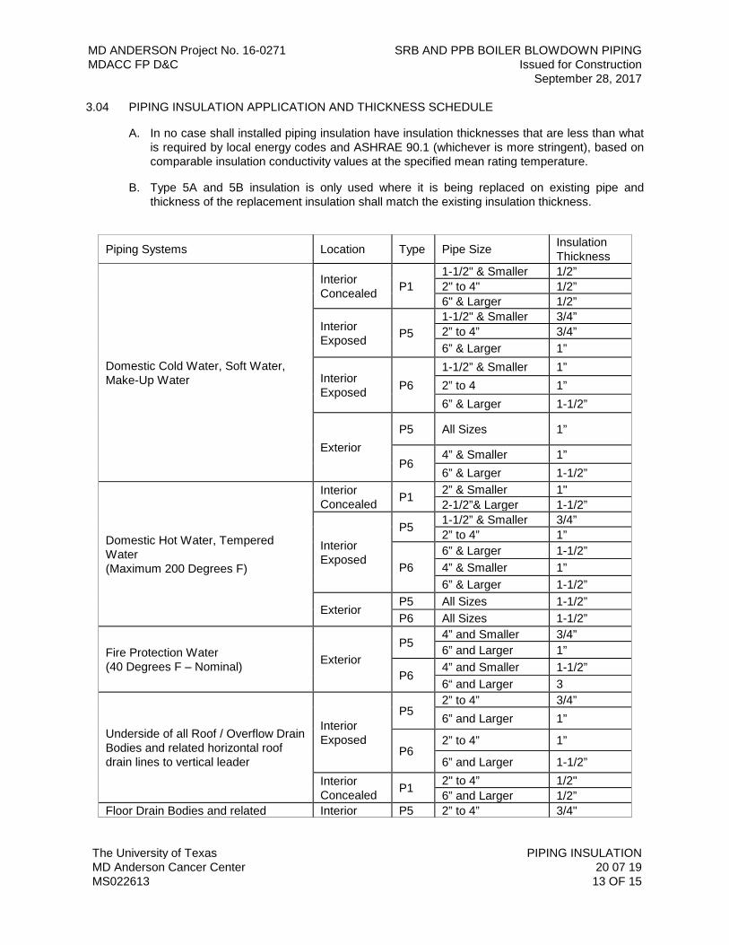
MD ANDERSON Project No. 16-0271 SRB AND PPB BOILER BLOWDOWN PIPING MDACC FP D&C Issued for Construction September 28, 2017
The University of Texas PIPING INSULATION MD Anderson Cancer Center 20 07 19 MS022613 13 OF 15
3.04 PIPING INSULATION APPLICATION AND THICKNESS SCHEDULE
A. In no case shall installed piping insulation have insulation thicknesses that are less than what is required by local energy codes and ASHRAE 90.1 (whichever is more stringent), based on comparable insulation conductivity values at the specified mean rating temperature.
B. Type 5A and 5B insulation is only used where it is being replaced on existing pipe and thickness of the replacement insulation shall match the existing insulation thickness.
Piping Systems Location Type Pipe Size Insulation Thickness
Domestic Cold Water, Soft Water, Make-Up Water
Interior Concealed P1
1-1/2" & Smaller 1/2” 2" to 4" 1/2” 6" & Larger 1/2”
Interior Exposed P5
1-1/2" & Smaller 3/4” 2” to 4” 3/4” 6” & Larger 1”
Interior Exposed P6
1-1/2” & Smaller 1” 2” to 4 1” 6” & Larger 1-1/2”
Exterior P5 All Sizes 1”
P6 4” & Smaller 1” 6” & Larger 1-1/2”
Domestic Hot Water, Tempered Water (Maximum 200 Degrees F)
Interior Concealed P1 2” & Smaller 1"
2-1/2”& Larger 1-1/2”
Interior Exposed
P5 1-1/2” & Smaller 3/4” 2” to 4” 1”
P6 6” & Larger 1-1/2” 4” & Smaller 1” 6” & Larger 1-1/2”
Exterior P5 All Sizes 1-1/2” P6 All Sizes 1-1/2”
Fire Protection Water (40 Degrees F – Nominal) Exterior
P5 4” and Smaller 3/4” 6” and Larger 1”
P6 4” and Smaller 1-1/2” 6“ and Larger 3
Underside of all Roof / Overflow Drain Bodies and related horizontal roof drain lines to vertical leader
Interior Exposed
P5 2” to 4” 3/4” 6” and Larger 1”
P6 2” to 4” 1”
6” and Larger 1-1/2” Interior Concealed P1 2" to 4” 1/2"
6” and Larger 1/2” Floor Drain Bodies and related Interior P5 2” to 4” 3/4"
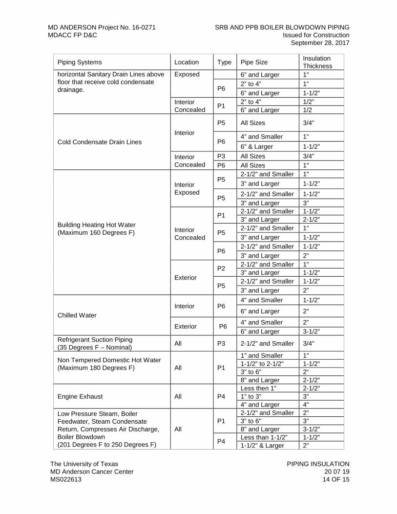
MD ANDERSON Project No. 16-0271 SRB AND PPB BOILER BLOWDOWN PIPING MDACC FP D&C Issued for Construction September 28, 2017
The University of Texas PIPING INSULATION MD Anderson Cancer Center 20 07 19 MS022613 14 OF 15
Piping Systems Location Type Pipe Size Insulation Thickness
horizontal Sanitary Drain Lines above floor that receive cold condensate drainage.
Exposed 6” and Larger 1"
P6 2” to 4” 1” 6” and Larger 1-1/2”
Interior Concealed P1 2” to 4” 1/2”
6” and Larger 1/2
Cold Condensate Drain Lines Interior
P5 All Sizes 3/4”
P6 4” and Smaller 1” 6” & Larger 1-1/2”
Interior Concealed
P3 All Sizes 3/4” P6 All Sizes 1"
Building Heating Hot Water (Maximum 160 Degrees F)
Interior Exposed
P5 2-1/2” and Smaller 1" 3" and Larger 1-1/2”
P5 2-1/2” and Smaller 1-1/2” 3" and Larger 3”
Interior Concealed
P1 2-1/2” and Smaller 1-1/2” 3" and Larger 2-1/2”
P5 2-1/2” and Smaller 1" 3" and Larger 1-1/2”
P6 2-1/2” and Smaller 1-1/2” 3" and Larger 2”
Exterior P2 2-1/2” and Smaller 1"
3" and Larger 1-1/2”
P5 2-1/2” and Smaller 1-1/2” 3" and Larger 2”
Chilled Water Interior P6
4" and Smaller 1-1/2”
6" and Larger 2"
Exterior P6 4” and Smaller 2” 6” and Larger 3-1/2”
Refrigerant Suction Piping (35 Degrees F – Nominal) All P3 2-1/2” and Smaller 3/4"
Non Tempered Domestic Hot Water (Maximum 180 Degrees F)
All P1
1" and Smaller 1" 1-1/2" to 2-1/2" 1-1/2" 3" to 6" 2“ 8" and Larger 2-1/2”
Engine Exhaust All P4 Less then 1" 2-1/2" 1" to 3" 3" 4" and Larger 4"
Low Pressure Steam, Boiler Feedwater, Steam Condensate Return, Compresses Air Discharge, Boiler Blowdown (201 Degrees F to 250 Degrees F)
All P1
2-1/2" and Smaller 2" 3” to 6" 3” 8" and Larger 3-1/2"
P4 Less than 1-1/2” 1-1/2" 1-1/2” & Larger 2"
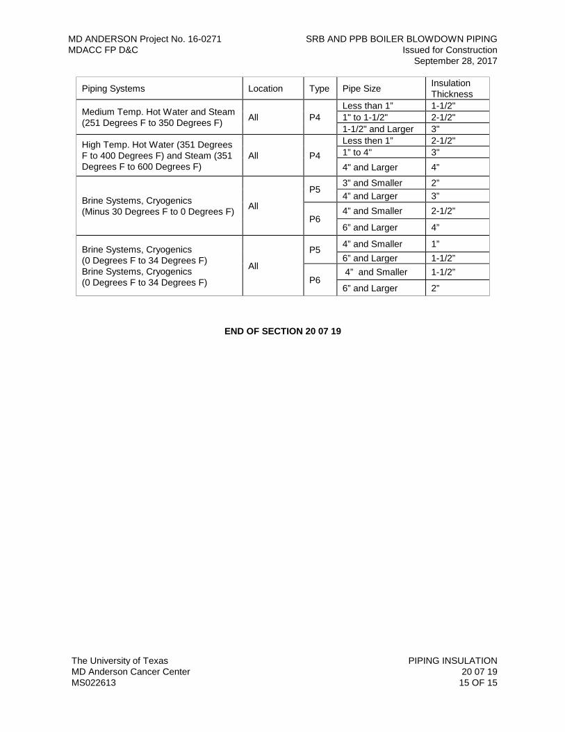
MD ANDERSON Project No. 16-0271 SRB AND PPB BOILER BLOWDOWN PIPING MDACC FP D&C Issued for Construction September 28, 2017
The University of Texas PIPING INSULATION MD Anderson Cancer Center 20 07 19 MS022613 15 OF 15
Piping Systems Location Type Pipe Size Insulation Thickness
Medium Temp. Hot Water and Steam (251 Degrees F to 350 Degrees F) All P4
Less than 1” 1-1/2" 1" to 1-1/2" 2-1/2" 1-1/2" and Larger 3"
High Temp. Hot Water (351 Degrees F to 400 Degrees F) and Steam (351 Degrees F to 600 Degrees F)
All P4 Less then 1” 2-1/2" 1” to 4" 3" 4" and Larger 4”
Brine Systems, Cryogenics (Minus 30 Degrees F to 0 Degrees F) All
P5 3” and Smaller 2” 4” and Larger 3”
P6 4” and Smaller 2-1/2”
6” and Larger 4”
Brine Systems, Cryogenics (0 Degrees F to 34 Degrees F) Brine Systems, Cryogenics (0 Degrees F to 34 Degrees F)
All
P5 4” and Smaller 1” 6” and Larger 1-1/2”
P6 4” and Smaller 1-1/2”
6” and Larger 2”
END OF SECTION 20 07 19
MD ANDERSON Project No. 16-0271 SRB AND PPB BOILER BLOWDOWN PIPING MDACC FP D&C Issued for Construction September 28, 2017
The University of Texas HYDRONIC PIPING MD Anderson Cancer Center 23 21 13 MS070213 1 OF 21
SECTION 23 21 13 – HYDRONIC PIPING
PART 1 - GENERAL
1.01 RELATED DOCUMENTS
A. Drawings and general provisions of the Contract, including General Conditions and Division 01 Specification Sections, apply to this Section.
B. Specifications throughout all Divisions of the Project Manual are directly applicable to this Section, and this Section is directly applicable to them.
1.02 SUMMARY
A. Furnish and install all labor, materials, equipment, tools and services and perform all the operations required in connection with, or associated with, the construction of complete hydronic piping systems, including chilled and heating hot water piping, condenser water piping process chilled or hot water piping, condensate drain piping and generator cooling water piping systems as indicated on the Drawings.
1.03 REFERENCE STANDARDS
A. The latest published edition of a reference shall be applicable to this Project unless identified by a specific edition date.
B. All reference amendments adopted prior to the effective date of this Contract shall be applicable to this Project.
C. All materials, installation and workmanship shall comply with the applicable requirements and standards addressed within the following references:
1. ANSI/ASME Sec 9 - Welding and Brazing Qualifications.
2. ASTM A53 – Standard Specification for Pipe, Steel, Black and Hot Dipped, Zinc Coated, Welded and Seamless.
3. ANSI/ASME B16.3 - Malleable Iron Threaded Fittings Class 150 and 300.
4. ANSI/ASME B16.9 – Factory-Made Wrought Butt welding Fittings.
5. ANSI/ASME B16.23 – Cast Copper Alloy Solder Drainage Fitting – DWV.
6. ANSI/ASME B16.29 – Wrought Copper and Wrought Copper Alloy Solder Joint Drainage Fittings – DWV.
7. ANSI/ASME B31.9 - Building Services Piping.
8. ASME B36.1 – Standardization of dimensions of welded and seamless wrought steel pipe for high or low temperatures and pressures.
9. ANSI/AWS D1.1 - Structural Welding Code.
MD ANDERSON Project No. 16-0271 SRB AND PPB BOILER BLOWDOWN PIPING MDACC FP D&C Issued for Construction September 28, 2017
The University of Texas HYDRONIC PIPING MD Anderson Cancer Center 23 21 13 MS070213 2 OF 21
10. ASTM A53 - Pipe, Steel, Black and Hot-Dipped Zinc Coated (Galvanized), Welded and Seamless, for Ordinary Uses.
11. ASTM A105 – Standard Specification for Carbon Steel Forgings for Pipe Applications.
12. ASTM A106 Grade B, Seamless or Electric Resistance Welded (ERW) piping.
13. ASTM A234 - Pipe Fittings of Wrought Carbon Steel and Alloy Steel for Moderate and Elevated Temperatures.
14. ASTM A312 – Standard Specification for Seamless and Welded Austenitic Stainless Steel Pipe.
15. ASTM A536 – Standard Specification for Ductile Iron Castings.
16. ASTM B88 – Standard Specification for Seamless Copper Water Tube.
1.04 QUALITY ASSURANCE
A. Valves: Manufacturer's name and pressure rating shall be clearly marked on the outside of the valve body.
B. All grooved joint couplings, fittings, flanges, valves, and specialties of the same type shall be the products of a single manufacturer. Grooving tools shall be of the same manufacturer as the grooved components.
C. Welding Materials and Procedures: Conform to Chapter V, ASME/ANSI B31.9 and applicable state labor regulations.
D. Welders Certification: Furnish in accordance with AWS D10.12 and ASME B31.9.
E. Each threaded fitting shall be stamped as specified by ANSI B16.3.
F. Each welded fitting shall be stamped as specified by ANSI B31.9.
1.05 SUBMITTALS
A. Product Data:
1. Submit product data on pipe materials, pipe fittings, valves, and accessories. Clearly indicate make, model, type, size, and pressure rating for each device.
2. Submittal data for all fittings shall include a letter signed by an official of the manufacturing company certifying compliance with these Specifications.
B. Record Documents:
1. Grooved joint couplings and fittings shall be shown on drawings and product submittals and shall be specifically identified with the applicable Victaulic or Anvil style or series designation.
2. Include welder’s certification of compliance in accordance with Chapter V, ASME/ANSI B31.9.
MD ANDERSON Project No. 16-0271 SRB AND PPB BOILER BLOWDOWN PIPING MDACC FP D&C Issued for Construction September 28, 2017
The University of Texas HYDRONIC PIPING MD Anderson Cancer Center 23 21 13 MS070213 3 OF 21
PART 2 - PRODUCTS
2.01 GENERAL
A. All materials shall meet or exceed all applicable referenced standards, federal, state and local requirements, and conform to codes and ordinances of authorities having jurisdiction.
B. Wall, Floor and Ceiling Plates:
1. Provide chrome-plated brass floor and ceiling plates.
C. Threaded Fittings:
1. All threaded fittings shall be USA factory made, wrought carbon or alloy steel threaded fittings conforming to ASTM A234 or malleable iron threaded fittings conforming to ASME B16.3.
2. Acceptable manufacturers: Grinnell, Tube Turn, Weld Bend Hackney, Taylor Forge or Ladish Company.
D. Grooved Fittings:
1. All grooved joint couplings, fittings, valves, and specialties shall be the products of a single manufacturer. Grooving tools shall be of the same manufacturer as the grooved components. Fittings shall comply with ASTM A536; ASTM A234; or factory fabricated from carbon steel pipe conforming to ASTM A53.
2. Acceptable Manufacturers: Victaulic Company of America, Anvil International.
3. Gaskets shall be verified as suitable for the intended system service, a minimum temperature of 250 degrees, fluid chemistry, and system pressure prior to installation. Gaskets shall be molded and produced by the coupling manufacturer.
E. Welded Fittings:
1. All welded fittings shall be USA factory made wrought carbon steel butt welding fittings conforming to ASTM Spec. A234 or ASME B16.9.
2. Acceptable manufacturers: Grinnell, Tube Turn, Weld Burn Hackney, Taylor forge or Ladish Company.
F. Flanges:
1. All 150 lb. and 300 lb. ANSI flanges shall be weld neck and shall be domestically manufactured, forged carbon steel, conforming to ANSI B16.5 and ASTM A-191 Grade I or II or A-105 as made by Tube Turn, Hackney or Ladish Company. Slip on flanges shall not be used. Complete test reports may be required for any fitting selected at random.
2. Flanges shall have the manufacturer’s trademark permanently identified in accordance with MSS SP-25. Contractor shall submit data for firm certifying compliance with these Specifications.
MD ANDERSON Project No. 16-0271 SRB AND PPB BOILER BLOWDOWN PIPING MDACC FP D&C Issued for Construction September 28, 2017
The University of Texas HYDRONIC PIPING MD Anderson Cancer Center 23 21 13 MS070213 4 OF 21
3. Bolts used shall be carbon steel bolts with semi-finished hexagon nuts of American Standard Heavy dimensions. All-thread rods will not be an acceptable substitute for flange bolts. Bolts shall have a tensile strength of 60,000 psi and an elastic limit of 30,000 psi.
4. All flanges shall be gasketed. Place gasket between flanges of flanged joints. Gaskets shall fit within the bolt circle on raised face flanges and shall be full face on flat face flanges. Gaskets shall be cut from 1/16 inch thick, non-metallic, non-asbestos gasket material suitable for operating temperatures from -150 degrees F to +750 degrees F, Klingerseal C-4400, Manville Style 60 service sheet packing or accepted substitution. Gaskets must be compatible with flowing fluid, temperature, and pressure of system.
G. Branch Connections:
1. For pipe 2 inches and smaller, use threaded fittings for steel pipe.
2. For 2-1/2 inches through 14 inches welded piping: When branch size is the same as or one size smaller than header size, use a welded tee. Use a Weld-o-let when branch is two or more sizes smaller than the header. For threaded branch connections, use a Thread-o-let welded to header.
3. No Branch connection shall be made by burning a hole in the main.
H. Copper Fittings:
1. Mechanically formed, drilled and extruded tee-branch connections shall not be permitted.
2.02 PIPE
A. TECO Distribution Pipe:
1. Pipe 2-1/2 inches and smaller: Black steel ASTM A106, Grade B, Schedule 80. seamless,
a. Fittings: Screwed.
b. Joints: Screwed.
c. Unions: Forged steel, ASTM A105, screwed with stainless steel seats.
2. Pipe 3 inches and larger: Black steel ASTM A106, Grade B, Standard weight seamless,
a. Fittings: ASTM A234 Carbon steel welding type.
b. Joints: Butt welded.
c. Flange: ANSI B16.5 Class 150, forged carbon steel.
B. Building Chilled Water and Heating Water Piping – 150 psi System:
1. Steel:
a. Pipe 2 inches and smaller: Black steel ASTM A106, Grade A or B, seamless, Schedule 40.
MD ANDERSON Project No. 16-0271 SRB AND PPB BOILER BLOWDOWN PIPING MDACC FP D&C Issued for Construction September 28, 2017
The University of Texas HYDRONIC PIPING MD Anderson Cancer Center 23 21 13 MS070213 5 OF 21
1) Fittings: Screwed, malleable iron, Class 150.
2) Joints: Screwed.
3) Unions: Forged steel, ASTM A105, screwed with stainless steel seats.
b. Pipe 2-1/2 inches and larger: Black steel ASTM A106, Grade B, seamless:
1) 2-1/2 inches through 12 inches – Schedule 40.
2) 14 inches through 36 inches – 0.375 inch wall thickness.
3) Fittings:
a) ASTM A234 carbon steel welding type, long radius type elbows unless specified otherwise on the Drawings.
b) ASTM A536 ductile iron; A234 carbon steel; or factory fabricated A53; grooved end long radius type elbows unless specified otherwise on the Drawings.
4) Joints:
a) Butt welded.
b) Grooved mechanical couplings.
5) Flange: ANSI B16.5 Class 150, forged carbon steel.
2. Steel ERW Pipe (Not to be used on HW systems):
a. 2 inches and smaller Black Steel ASTM A106 Gr. A or B – Schedule 40.
1) 2" and under ASTM A47, malleable iron, 150 lb.
2) Joints screwed
3) Unions: Forged steel, ASTM A105, screwed with stainless steel seats.
b. 2½ inches to 24 inches Black Steel ASTM A53 Grade B,
1) 2½ inches through 12 inches – Schedule 40.
2) 14 inches through 24 inches – 0.375 inch wall thickness.
c. Fittings: ASTM A234 Carbon steel welding type.
d. Joints: Butt welded.
e. Flange: ANSI B16.5 Class 150, forged carbon steel.
3. Copper:
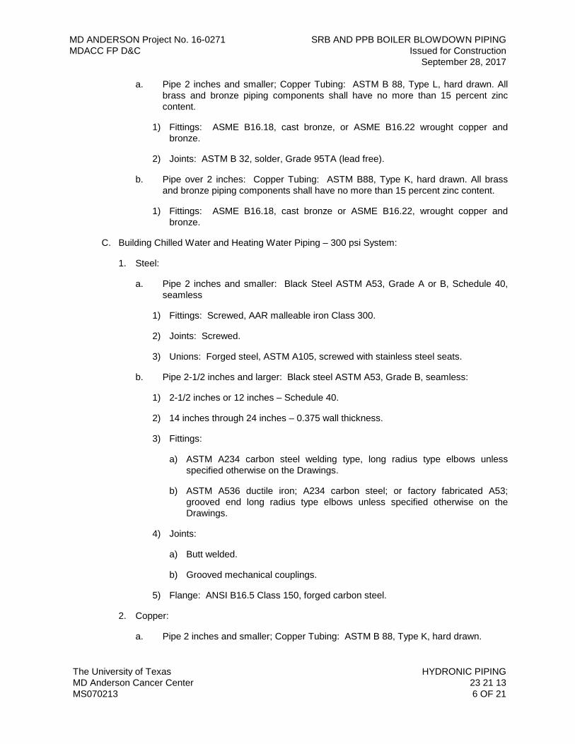
MD ANDERSON Project No. 16-0271 SRB AND PPB BOILER BLOWDOWN PIPING MDACC FP D&C Issued for Construction September 28, 2017
The University of Texas HYDRONIC PIPING MD Anderson Cancer Center 23 21 13 MS070213 6 OF 21
a. Pipe 2 inches and smaller; Copper Tubing: ASTM B 88, Type L, hard drawn. All brass and bronze piping components shall have no more than 15 percent zinc content.
1) Fittings: ASME B16.18, cast bronze, or ASME B16.22 wrought copper and bronze.
2) Joints: ASTM B 32, solder, Grade 95TA (lead free).
b. Pipe over 2 inches: Copper Tubing: ASTM B88, Type K, hard drawn. All brass and bronze piping components shall have no more than 15 percent zinc content.
1) Fittings: ASME B16.18, cast bronze or ASME B16.22, wrought copper and bronze.
C. Building Chilled Water and Heating Water Piping – 300 psi System:
1. Steel:
a. Pipe 2 inches and smaller: Black Steel ASTM A53, Grade A or B, Schedule 40, seamless
1) Fittings: Screwed, AAR malleable iron Class 300.
2) Joints: Screwed.
3) Unions: Forged steel, ASTM A105, screwed with stainless steel seats.
b. Pipe 2-1/2 inches and larger: Black steel ASTM A53, Grade B, seamless:
1) 2-1/2 inches or 12 inches – Schedule 40.
2) 14 inches through 24 inches – 0.375 wall thickness.
3) Fittings:
a) ASTM A234 carbon steel welding type, long radius type elbows unless specified otherwise on the Drawings.
b) ASTM A536 ductile iron; A234 carbon steel; or factory fabricated A53; grooved end long radius type elbows unless specified otherwise on the Drawings.
4) Joints:
a) Butt welded.
b) Grooved mechanical couplings.
5) Flange: ANSI B16.5 Class 150, forged carbon steel.
2. Copper:
a. Pipe 2 inches and smaller; Copper Tubing: ASTM B 88, Type K, hard drawn.
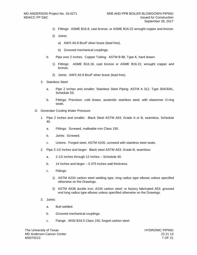
MD ANDERSON Project No. 16-0271 SRB AND PPB BOILER BLOWDOWN PIPING MDACC FP D&C Issued for Construction September 28, 2017
The University of Texas HYDRONIC PIPING MD Anderson Cancer Center 23 21 13 MS070213 7 OF 21
1) Fittings: ASME B16.8, cast bronze, or ASME B16.22 wrought copper and bronze.
2) Joints:
a) AWS A5.8 BcuP silver braze (lead free).
b) Grooved mechanical couplings.
b. Pipe over 2 inches: Copper Tubing: ASTM B 88, Type K, hard drawn.
1) Fittings: ASME B16.18, cast bronze or ASME B16.22, wrought copper and bronze.
2) Joints: AWS A5.8 BcuP silver braze (lead free).
3. Stainless Steel:
a. Pipe 2 inches and smaller; Stainless Steel Piping: ASTM A 312, Type 304/304L, Schedule 5S.
b. Fittings: Precision, cold drawn, austenitic stainless steel, with elastomer O-ring seals.
D. Generator Cooling Water Pressure:
1. Pipe 2 inches and smaller: Black Steel ASTM A53, Grade A or B, seamless, Schedule 40.
a. Fittings: Screwed, malleable iron Class 150.
b. Joints: Screwed.
c. Unions: Forged steel, ASTM A105, screwed with stainless steel seats.
2. Pipe 2-1/2 inches and larger: Black steel ASTM A53, Grade B, seamless:
a. 2-1/2 inches through 12 inches – Schedule 40.
b. 14 inches and larger – 0.375 inches wall thickness.
c. Fittings:
1) ASTM A234 carbon steel welding type, long radius type elbows unless specified otherwise on the Drawings.
2) ASTM A536 ductile iron; A234 carbon steel; or factory fabricated A53; grooved end long radius type elbows unless specified otherwise on the Drawings.
3. Joints:
a. Butt welded.
b. Grooved mechanical couplings.
c. Flange: ANSI B16.5 Class 150, forged carbon steel.
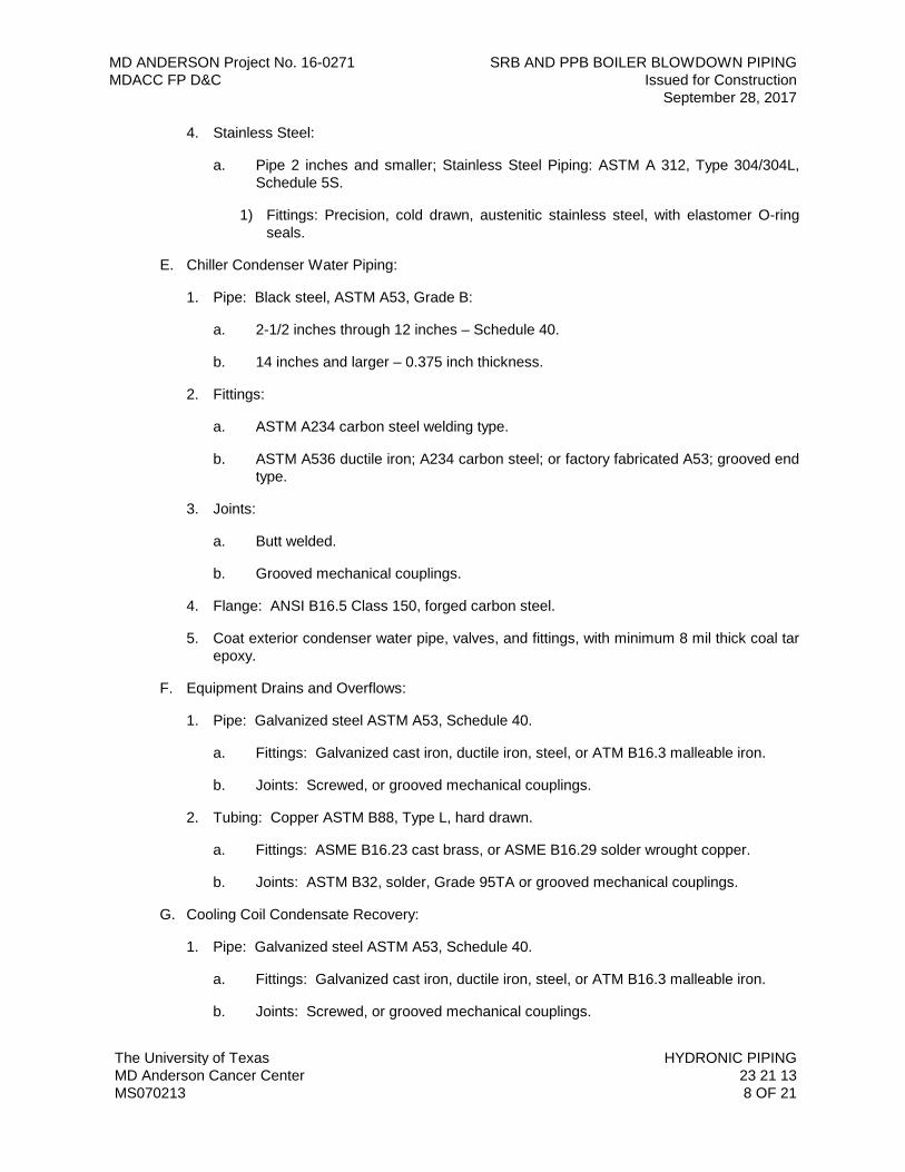
MD ANDERSON Project No. 16-0271 SRB AND PPB BOILER BLOWDOWN PIPING MDACC FP D&C Issued for Construction September 28, 2017
The University of Texas HYDRONIC PIPING MD Anderson Cancer Center 23 21 13 MS070213 8 OF 21
4. Stainless Steel:
a. Pipe 2 inches and smaller; Stainless Steel Piping: ASTM A 312, Type 304/304L, Schedule 5S.
1) Fittings: Precision, cold drawn, austenitic stainless steel, with elastomer O-ring seals.
E. Chiller Condenser Water Piping:
1. Pipe: Black steel, ASTM A53, Grade B:
a. 2-1/2 inches through 12 inches – Schedule 40.
b. 14 inches and larger – 0.375 inch thickness.
2. Fittings:
a. ASTM A234 carbon steel welding type.
b. ASTM A536 ductile iron; A234 carbon steel; or factory fabricated A53; grooved end type.
3. Joints:
a. Butt welded.
b. Grooved mechanical couplings.
4. Flange: ANSI B16.5 Class 150, forged carbon steel.
5. Coat exterior condenser water pipe, valves, and fittings, with minimum 8 mil thick coal tar epoxy.
F. Equipment Drains and Overflows:
1. Pipe: Galvanized steel ASTM A53, Schedule 40.
a. Fittings: Galvanized cast iron, ductile iron, steel, or ATM B16.3 malleable iron.
b. Joints: Screwed, or grooved mechanical couplings.
2. Tubing: Copper ASTM B88, Type L, hard drawn.
a. Fittings: ASME B16.23 cast brass, or ASME B16.29 solder wrought copper.
b. Joints: ASTM B32, solder, Grade 95TA or grooved mechanical couplings.
G. Cooling Coil Condensate Recovery:
1. Pipe: Galvanized steel ASTM A53, Schedule 40.
a. Fittings: Galvanized cast iron, ductile iron, steel, or ATM B16.3 malleable iron.
b. Joints: Screwed, or grooved mechanical couplings.
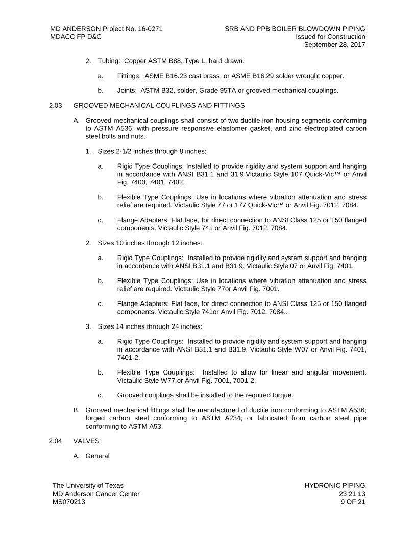
MD ANDERSON Project No. 16-0271 SRB AND PPB BOILER BLOWDOWN PIPING MDACC FP D&C Issued for Construction September 28, 2017
The University of Texas HYDRONIC PIPING MD Anderson Cancer Center 23 21 13 MS070213 9 OF 21
2. Tubing: Copper ASTM B88, Type L, hard drawn.
a. Fittings: ASME B16.23 cast brass, or ASME B16.29 solder wrought copper.
b. Joints: ASTM B32, solder, Grade 95TA or grooved mechanical couplings.
2.03 GROOVED MECHANICAL COUPLINGS AND FITTINGS
A. Grooved mechanical couplings shall consist of two ductile iron housing segments conforming to ASTM A536, with pressure responsive elastomer gasket, and zinc electroplated carbon steel bolts and nuts.
1. Sizes 2-1/2 inches through 8 inches:
a. Rigid Type Couplings: Installed to provide rigidity and system support and hanging in accordance with ANSI B31.1 and 31.9.Victaulic Style 107 Quick-Vic™ or Anvil Fig. 7400, 7401, 7402.
b. Flexible Type Couplings: Use in locations where vibration attenuation and stress relief are required. Victaulic Style 77 or 177 Quick-Vic™ or Anvil Fig. 7012, 7084.
c. Flange Adapters: Flat face, for direct connection to ANSI Class 125 or 150 flanged components. Victaulic Style 741 or Anvil Fig. 7012, 7084.
2. Sizes 10 inches through 12 inches:
a. Rigid Type Couplings: Installed to provide rigidity and system support and hanging in accordance with ANSI B31.1 and B31.9. Victaulic Style 07 or Anvil Fig. 7401.
b. Flexible Type Couplings: Use in locations where vibration attenuation and stress relief are required. Victaulic Style 77or Anvil Fig. 7001.
c. Flange Adapters: Flat face, for direct connection to ANSI Class 125 or 150 flanged components. Victaulic Style 741or Anvil Fig. 7012, 7084..
3. Sizes 14 inches through 24 inches:
a. Rigid Type Couplings: Installed to provide rigidity and system support and hanging in accordance with ANSI B31.1 and B31.9. Victaulic Style W07 or Anvil Fig. 7401, 7401-2.
b. Flexible Type Couplings: Installed to allow for linear and angular movement. Victaulic Style W77 or Anvil Fig. 7001, 7001-2.
c. Grooved couplings shall be installed to the required torque.
B. Grooved mechanical fittings shall be manufactured of ductile iron conforming to ASTM A536; forged carbon steel conforming to ASTM A234; or fabricated from carbon steel pipe conforming to ASTM A53.
2.04 VALVES
A. General
MD ANDERSON Project No. 16-0271 SRB AND PPB BOILER BLOWDOWN PIPING MDACC FP D&C Issued for Construction September 28, 2017
The University of Texas HYDRONIC PIPING MD Anderson Cancer Center 23 21 13 MS070213 10 OF 21
1. All valves used in 150 psi circulating systems shall be ANSI Class 150. All valves in 300 psi systems shall be Class 300 valves and shall be constructed of all ASTM B-61or B-584 composition. All gate, globe and angle valves shall be screw-over-bonnet design. Metal used in the stems of all bronze gate, globe and angle valves shall conform to ASTM B371 Alloy 694, ASTM B99 Alloy 651 or other corrosion resistant equivalents. Secure written approvals by Owner for the use of alternative materials.
2. The following manufacturers are acceptable: Milwaukee, NIBCO, Keystone, KITZ, Crane, Dezurik, Daniels, Williams, Velan Vogt, Victaulic and Anvil.
3. All iron body valves shall have the pressure containing parts constructed of ASTM designated of A536 grade 65-45-12 ductile iron or A126 class B iron. Stem material shall meet ASTM A582 or A564 stainless steel, B16 Alloy 360, or ASTM 371 Alloy 876 silicon bronze or its approved equivalent model by listed manufacturers.
4. All cast steel body valves shall have the pressure containing parts constructed of ASTM designation A-216-GR-WCB carbon steel. Stems shall meet ASTM designation A-186-F6 chromium stainless steel. Seat ring shall be hard faced carbon steel or 13^ chromium A-182-F6 stainless. Handwheels shall be A47 grade 35018 malleable iron or ductile iron ASTM A536.
5. All forged steel body valves shall have the pressure containing parts constructed of ASTM 105, Grade 2 forged carbon steel. Seat and wedges shall meet ASTM-A-182-F6 chromium stainless steel. Seat rings shall be hard faced. Valves shall conform to ANSI B16-34 pressure-temperature rating.
6. All gate valves, globe valves, angle valves and shutoff valves shall have malleable iron hand wheels, except iron body valves 2-½ inches and larger which may have either malleable iron or ASTM A-126 Class B, gray iron hand wheels.
7. Packing for all valves shall be free of asbestos fibers and selected for the pressure-temperature service of the valve. It is incumbent upon the manufacturer to select the best quality, standard packing for the intended valve service.
8. Provide stem extensions on all insulated valves.
9. Valve chain operators shall be of cast iron or malleable iron and designed to provide positive grip on wheel. Provide chain guide to prevent chain from slipping or jumping on wheel. Employ rustproof chain complete with closing link of sufficient length to operate at 6 feet-6 inches above floor level.
10. Provide valves suitable for connection to adjoining pipe as specified for pipe joints above. Use valves that are full size of pipe in which installed.
B. Gate Valves:
1. 150 Pound Class Valves:
a. Threaded pipe 2 inches and smaller: KITZ 42T, Milwaukee 1151, NIBCO T-134, or approved equivalent model by listed manufacturers, bronze body, union bonnet, rising stem, solid wedge disc, threaded.
MD ANDERSON Project No. 16-0271 SRB AND PPB BOILER BLOWDOWN PIPING MDACC FP D&C Issued for Construction September 28, 2017
The University of Texas HYDRONIC PIPING MD Anderson Cancer Center 23 21 13 MS070213 11 OF 21
b. Welded pipe 2-1/2 inches and larger: KITZ 72, Milwaukee F-2885A, NIBCO F-617-0, or approved equivalent model by listed manufacturers, iron body, flanged, OS&Y (Outside Screw and Yoke), rising stem, solid wedge.
2. 300 Pound Class Valves:
a. Threaded pipe 2 inches and smaller: KITZ 37, Milwaukee F-2894A, NIBCO T-174-A or accepted substitute, bronze body, union bonnet, rising stem, solid wedge with integral seats threaded.
b. Welded pipe 2-1/2 inches and larger: NIBCO F-667-0 or accepted substitute, iron body, OS&Y, rising stem, solid wedge, flanged.
3. Bolted bonnet with OS&Y (outside screw and yoke) and rising stem design, integral seats, with pressure temperature rating conforming to ANSI B16-34; KITZ 37, Milwaukee 1182, , NIBCO T-174-A for 2 inches and smaller.
C. Globe Valves:
1. 150 Pound Class Valves:
a. Threaded pipe 2 inches and smaller: KITZ 09, Milwaukee 590T, NIBCO T235-Y, Anvil equivalent or Victaulic TA Series 787 Y-Pattern, 150-pound screwed, inside screw, rising stem, bronze body, union Bonnet.
b. Welded pipe 2-1/2 inches and larger: KITZ 76, Milwaukee F-2981A, NIBCO F-718-B, Anvil equivalent or Victaulic TA Series 788 or 789(grooved) Y-Pattern, Cast Iron with Brass Trim.
2. 300 Pound Class Valves:
a. Threaded pipe 2 inches and smaller: KITZ 17S Milwaukee 593A, NIBCO T276-AP, Class 300 screwed, inside screw rising stem, bronze body, union bonnet, stainless steel disc.
b. Welded pipe 2-1/2 inches and larger. Milwaukee F-2983-M, (import) , NIBCO F-768-B, Class 250 iron body, flanged, bolted bonnet, Brass Trim.
D. Soft Seated Butterfly Valves:
1. 200 Pound Soft Seated:
a. KITZ 6123, Milwaukee ML233-E, NIBCO LD-2000 (flanged),, Victaulic Vic®-300 MasterSeal™/ Victaulic AGS Vic®-300 (grooved), Anvil7700 Series, 8200 Series or approved equal.
b. Ductile Iron body with Aluminum Bronze Disc, 400 series stainless steel stem offset from the disk centerline to provide full 360 degree circumferential seating.
c. Temperature range from -50°F to +200°F.
d. Valves 6 inches and smaller shall have lockable hand lever operators; 8 inches and larger shall have gear operators.
MD ANDERSON Project No. 16-0271 SRB AND PPB BOILER BLOWDOWN PIPING MDACC FP D&C Issued for Construction September 28, 2017
The University of Texas HYDRONIC PIPING MD Anderson Cancer Center 23 21 13 MS070213 12 OF 21
e. All butterfly valves shall be suitable for bi-directional dead-end service without the need for a downstream flange.
E. High Performance Butterfly Valves:
1. 150 Pound Soft Seated Class Valves:
a. Milwaukee 6 inch and smaller HP1LCS4212, 8 inch and larger HP1LCS4213, NIBCO LCS-6822, carbon steel lug body valves. ANSI rated Class 150.
b. Valves to provide tight shutoff up to 285 psi.
c. Valves 6 inches and smaller shall have lockable hand lever operators; 8 inches and larger shall have gear operators
d. Provide 316 or UNS-S31803 stainless shaft, cast stainless steel disc, and soft seat.
e. Temperature range from -50°F to +200°F.
2. 300 Pound Class Valves: Milwaukee HP3LCS4213, NIBCO LCS-7822 300 lb. ANSI class raised face, lug body, carbon steel body, stainless steel pin and shaft and disc, soft seat,and gear operators.
F. Check Valves:
1. 150 Pound Class Valves:
a. Threaded pipe 2 inches and smaller. KITZ 29, Milwaukee 508, NIBCO T453-B, bronze body, Class 200, screwed connection, regrinding disc and seat with screw in cap.
b. Welded or Grooved pipe 2-1/2 inches and larger. Milwaukee 1800 series, NIBCO F910-B. Flanged style, or Victaulic Series 716 or 779 or Anvil7800 Series grooved style spring-loaded type. Rate for 150 psig working pressure; Cast or ductile Iron body, Bronze plates and 316 Stainless Steel springs.
G. Plug Valves:
1. 150 Pound Class Valves:
a. Threaded pipe 2 inches and smaller: Dezurik 128 S 1 RS 26, Keystone 542, 150-pound screwed, eccentric plug valve, carbon steel or semi steel body, Buna-N faced plug, lever operated, nonlubricated, short pattern plug valve.
b. Welded pipe 2-1/2 inches and larger: Dezurik 128 F 1 RS 26, Homestead 583, or Victaulic Series 377 or Anvil equivalent. 150-pound flanged or grooved eccentric carbon steel or semi steel, Hycar or Buna-N faced plug, manually operated, nonlubricated, short pattern plug.
2. 300 Pound Class Valves:
MD ANDERSON Project No. 16-0271 SRB AND PPB BOILER BLOWDOWN PIPING MDACC FP D&C Issued for Construction September 28, 2017
The University of Texas HYDRONIC PIPING MD Anderson Cancer Center 23 21 13 MS070213 13 OF 21
a. Threaded pipe 2 inches and smaller: Tufline 066, Powerll 3058. 300 psi working pressure, cast carbon steel body and plug, threaded end valve, bolted bonnet, nonlubricated or lubricated with lubricant suitable for water -20 degrees F to 450 degrees F temperature, wrench operated.
b. Flanged piping 2-½ inches, cast carbon steel body and plug conforming to ASTM A216, Gr. WCB. Gear operated, bolted gland. Flanged per ANSI B16.5. Pipe sizes 4 inches through 12 inches. Nonlubricated or lubricated with lubricant suitable for water -20 degrees F to 450 degrees F temperature, 100 percent port.
H. Ball Valves:
1. Threaded pipe 2 inches and smaller: KITZ 68M with ISE Stem Extension and built in memory stop device, Milwaukee BA400-SXM for 3” Milwaukee BA100-SXM, NIBCO T 585-70-66-LL. For threaded pipe 2-1/2 inches to 3 inches: Crane 9303-S or approved equivalent model by listed manufacturers.
a. Threaded full port two-piece bronze body (ASTM-B584 Alloy 844, ASTM B61, or ASTM B62 (ASTM Approved Alloys” only).
b. Stainless steel ball and stem, blowout proof stem with stem extension made of non-thermal conducting material and having an adjustable memory stop after insulation is installed.
c. Ball valves shall be provided with SS lockable handles and locking devices or KITZ 68M Stem Extension and built in memory stop device.
2. Welded or grooved pipe 2-1/2 inches and larger: Milwaukee F20-CS-150-F-02 , NIBCO F-515-CS-66FS or accepted substitute for 150 pound Class; Milwaukee F20-CS-300-F-02 , NIBCO F-535-CS-66FS for 300 pound class, split steel body, full bore, blowout proof stem with, flanged connections, or Victaulic Series 726 with grooved connections or Anvil Series 7500.
PART 3 - EXECUTION
3.01 PREPARATION
A. Ream pipe and tube ends. Remove burrs. Bevel plain end ferrous pipe.
B. Remove scale and dirt on inside and outside before assembly.
C. Prepare piping connections to equipment with flanges or unions.
D. After completion, fill, clean, and treat systems.
3.02 PIPING STORAGE REQUIREMENT
A. All ERW and seamless piping shall be clearly identified and stored on separate construction pipe racks to prevent the intermixing of piping.
B. Shop fabricated piping spool and pup pieces of ERW and seamless pipe shall be clearly identified and separated in the lay down yard to prevent the intermixing of piping.
MD ANDERSON Project No. 16-0271 SRB AND PPB BOILER BLOWDOWN PIPING MDACC FP D&C Issued for Construction September 28, 2017
The University of Texas HYDRONIC PIPING MD Anderson Cancer Center 23 21 13 MS070213 14 OF 21
3.03 INSTALLATION
A. Installation shall meet or exceed all applicable federal, state and local requirements, referenced standards and conform to codes and ordinances of authorities having jurisdiction.
B. All valve installations shall be in accordance with manufacturer’s published recommendations.
C. Pipe Installation:
1. All the various piping systems shall be made up straight and true and run in orderly manner, plumb and parallel to building structural. Install piping to conserve building space. Coordinate location with other trades and do not interfere with use of space for other work.
2. Piping shall follow as closely as possible the routes shown on Drawings which take into consideration conditions to be met at the Site.
3. Should any unforeseen conditions arise, lines shall be changed or rerouted after proper approval has been obtained.
4. All piping shall be installed with due regard to expansion and contraction and so as to prevent excessive strain and stress in the piping, in connections, or in equipment to which the lines are connected.
5. Group piping whenever practical at common elevations.
6. Slope piping and arrange system to drain at low points. Use eccentric reducers where applicable to maintain the bottom of pipe level.
7. Branch tap connections are to be from the top to horizontal position of pipe run.
8. Where pipe support members are welded to structural building framing, scrape, brush clean, and apply one coat of zinc rich primer to welding.
9. Provide and install Pete’s plugs adjacent to thermo wells for electronic temperature sensors, to electronic pressure sensors and install Pete’s plugs adjacent where shown or noted on piping drawings or drawing details. The piping taps for the Pete’s plugs, permanently mounted pressure gauges, and instruments sensors shall be a minimum size of ½ inch schedule 40 pipe and be able to isolate them with a ½ inch stainless steel ball valve. Systems provided with pressure independent control valves shall be provided with a Pete’s plug downstream of the control valve, to facilitate verification of the valve manufacturer’s recommended water pressure drop across the pressure independent control valve.
10. Provide clearance for installation of insulation, and access to valves and fittings.
11. Prepare pipe, fittings, supports, and accessories for finish painting. Chilled water piping insulated with cellular glass does not require finish painting.
12. All piping shall be clean when it is installed. Before installation it shall be checked to assure it is the correct material to be used on the piping system, upended, swabbed if necessary, and all rust or dirt from storage or from lying on the ground shall be removed.
MD ANDERSON Project No. 16-0271 SRB AND PPB BOILER BLOWDOWN PIPING MDACC FP D&C Issued for Construction September 28, 2017
The University of Texas HYDRONIC PIPING MD Anderson Cancer Center 23 21 13 MS070213 15 OF 21
13. Where leaks occur, the pipe shall be repaired and the tests repeated. No leaks shall be corrected by peening. Defective piping and joints shall be removed and replaced.
14. Procedure of Assembling Screw Pipe Fittings: All screw joints shall be made with taper threads, properly cut. Joints shall be made tight with Teflon tape or Teflon-based compound appropriate to the medium, material and temperature range of the system. Compound shall be applied to the pipe threads only and not to fittings. When threads are cut on pipes, the ends shall be carefully reamed to remove any burrs. Before installing pipe that has been cut and threaded, the lengths of pipe shall be upended and hammered to remove all shavings and foreign material.
D. Valve Installation:
1. Locate all valves such that the removal of their bonnets is possible. All flanged valves shown in horizontal lines with the valve stem in a horizontal position shall be positioned so the valve stem is inclined one bolt hole above the horizontal position.
2. Screw pattern valves placed in horizontal lines shall be installed with their valve stems include at an angle of a minimum of 30 degrees above the horizontal position.
3. Pressure independent control valves shall be installed in accordance with valve manufacturer’s published installation instructions, with regard to orientation, clearances, and lengths of straight pipe upstream and downstream of the valve.
4. All valves must be true and straight at the time the system is tested and inspected for final acceptance.
5. Valves shall be installed as nearly as possible to the locations indicated in the Drawings. Any change in valve location must be so indicated on the Record As-Built Drawings.
6. Provide line shut-off valves at locations required for proper operation, servicing and troubleshooting of the HVAC hydronic distribution systems and connected components. Locations shall include but not be limited to the following; at each piece of equipment, at each branch take-off from mains, at the base of each riser, where recommended by equipment manufacturers and at strategic locations to allow sectional isolation while limiting disruption of services to large portions of the system.
7. All valves must be of threaded or flanged type. No solder connected valves shall be used on this Project.
8. Equipment, valves, expansion joints, relief devices, strainers, etc., must be removed or isolated during the test if the pressure/force ratings of the devices are not as high as that specified for the test. Piping shall be drained and protected any time ambient temperature is below freezing.
9. Where leaks occur, the pipe shall be repaired and the tests repeated. No leaks shall be corrected by peening. Defective piping and joints shall be removed and replaced.
10. All threaded valves.installed in copper piping shall be provided with copper or bronze male adapters on each side of valves. Sweat solder adapters to pipe before installing valves.
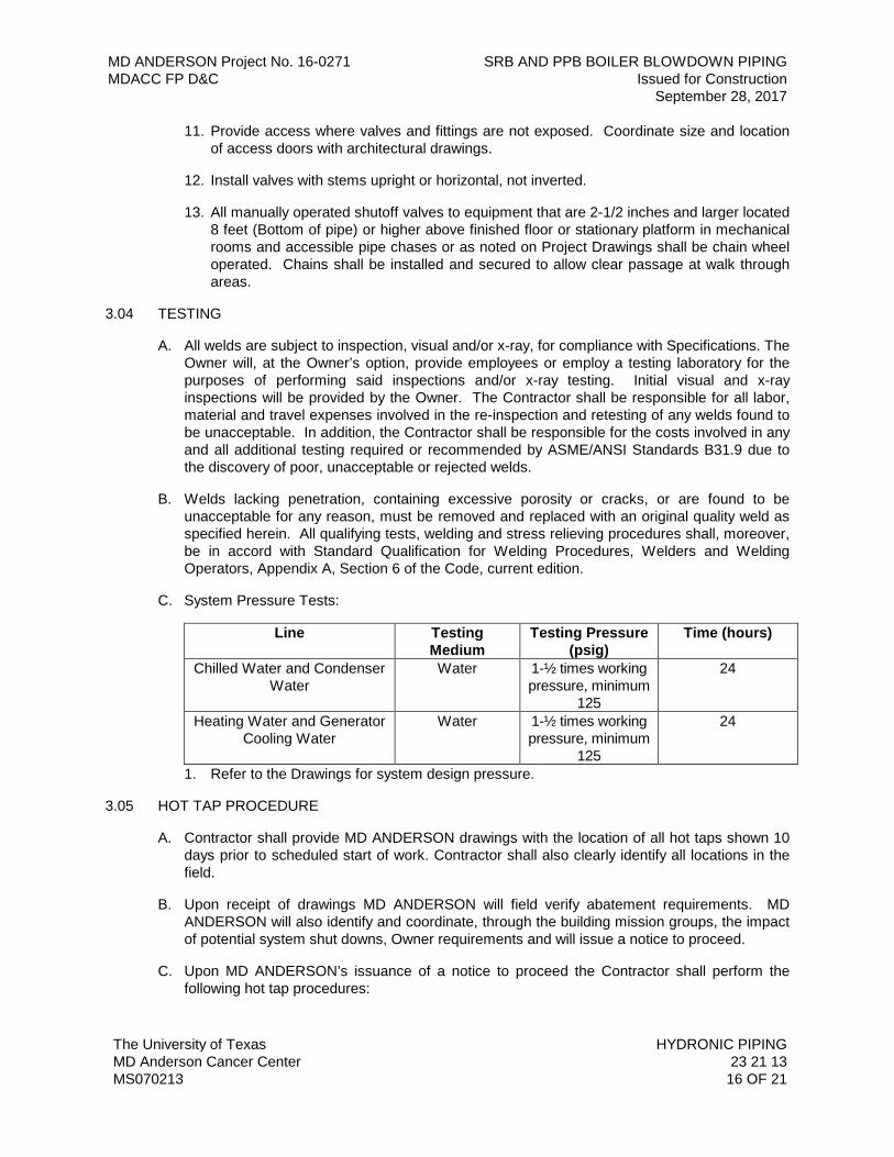
MD ANDERSON Project No. 16-0271 SRB AND PPB BOILER BLOWDOWN PIPING MDACC FP D&C Issued for Construction September 28, 2017
The University of Texas HYDRONIC PIPING MD Anderson Cancer Center 23 21 13 MS070213 16 OF 21
11. Provide access where valves and fittings are not exposed. Coordinate size and location of access doors with architectural drawings.
12. Install valves with stems upright or horizontal, not inverted.
13. All manually operated shutoff valves to equipment that are 2-1/2 inches and larger located 8 feet (Bottom of pipe) or higher above finished floor or stationary platform in mechanical rooms and accessible pipe chases or as noted on Project Drawings shall be chain wheel operated. Chains shall be installed and secured to allow clear passage at walk through areas.
3.04 TESTING
A. All welds are subject to inspection, visual and/or x-ray, for compliance with Specifications. The Owner will, at the Owner’s option, provide employees or employ a testing laboratory for the purposes of performing said inspections and/or x-ray testing. Initial visual and x-ray inspections will be provided by the Owner. The Contractor shall be responsible for all labor, material and travel expenses involved in the re-inspection and retesting of any welds found to be unacceptable. In addition, the Contractor shall be responsible for the costs involved in any and all additional testing required or recommended by ASME/ANSI Standards B31.9 due to the discovery of poor, unacceptable or rejected welds.
B. Welds lacking penetration, containing excessive porosity or cracks, or are found to be unacceptable for any reason, must be removed and replaced with an original quality weld as specified herein. All qualifying tests, welding and stress relieving procedures shall, moreover, be in accord with Standard Qualification for Welding Procedures, Welders and Welding Operators, Appendix A, Section 6 of the Code, current edition.
C. System Pressure Tests:
Line Testing Medium
Testing Pressure (psig)
Time (hours)
Chilled Water and Condenser Water
Water 1-½ times working pressure, minimum
125
24
Heating Water and Generator Cooling Water
Water 1-½ times working pressure, minimum
125
24
1. Refer to the Drawings for system design pressure.
3.05 HOT TAP PROCEDURE
A. Contractor shall provide MD ANDERSON drawings with the location of all hot taps shown 10 days prior to scheduled start of work. Contractor shall also clearly identify all locations in the field.
B. Upon receipt of drawings MD ANDERSON will field verify abatement requirements. MD ANDERSON will also identify and coordinate, through the building mission groups, the impact of potential system shut downs, Owner requirements and will issue a notice to proceed.
C. Upon MD ANDERSON’s issuance of a notice to proceed the Contractor shall perform the following hot tap procedures:
MD ANDERSON Project No. 16-0271 SRB AND PPB BOILER BLOWDOWN PIPING MDACC FP D&C Issued for Construction September 28, 2017
The University of Texas HYDRONIC PIPING MD Anderson Cancer Center 23 21 13 MS070213 17 OF 21
1. Preparation
a. Remove insulation at identified and approved hot tap locations and save for reinstallation as noted below.
b. Ultra-sound pipe at each weld location to verify pipe thickness. If pipe fails to pass ultra-sound follow procedure outlined in paragraph A to establish new tap location.
c. Temporarily reinstall pipe insulation upon completion of ultra-sound to prevent condensation.
d. Repeat above listed steps on all approved hot tap locations.
2. Installation
a. Remove insulation as required for installation of scheduled hot tap.
b. Weld saddle sleeve to pipe. All welds shall be made as per 15510-1.06-B
c. Install new valve on saddle sleeve.
d. Install blind flange on valve to prevent accidental opening.
e. Pressure test valve/seating to one and a half (1-1/2) times design operating pressure for 24 hours. MD ANDERSON representative shall witness this test.
f. Upon passing pressure test and prior to hot tapping pipe:
1) Verify that MD ANDERSON has staff ready to perform emergency shut-off procedures.
2) Verify emergency patch is on location and sized to match pipe being tapped.
3) Verify cleaning company is on call with portable shop vacuum(s).
g. Hot tap pipe, remove plug and wire to valve handle.
h. Clean all strainers in pipes affected by hot taps made that day.
i. Reinsulate pipe.
j. Repeat above listed steps for all remaining taps.
D. Unless approved by Owner all hot taps in horizontal lines shall be made at or above center line of pipe.
3.06 TRAINING
A. Victaulic Company shall provide on-site training for Contractor’s field personnel in the use of grooving tools, application of groove, and installation of grooved end couplings. The manufactures representative shall periodically visit the jobsite and provide the contractor information concerning the best recommended practices in grooved product installation. A distributor’s sales representative is not considered qualified to conduct the training or jobsite visit(s).
MD ANDERSON Project No. 16-0271 SRB AND PPB BOILER BLOWDOWN PIPING MDACC FP D&C Issued for Construction September 28, 2017
The University of Texas HYDRONIC PIPING MD Anderson Cancer Center 23 21 13 MS070213 18 OF 21
3.07 APPLICATION
A. Install valves and unions at equipment connections. Install unions on equipment side of valves. Provide dielectric isolation only where non-ferrous components connect to ferrous components.
B. Provide EPDM gasket material with a maximum service temperature of 120 degrees C at all hot water dielectric union installations.
C. Install brass male adapters each side of valves in copper piped system. Sweat solder adapters to pipe.
D. Install ball valves in piping 3 inches and smaller and butterfly valves in piping 4 inches and larger for shut-off and to isolate equipment, parts of systems, or vertical risers.
E. Install ball valves in piping 2 inches and smaller and butterfly valves in piping 2-1/2 inches and larger for throttling, bypass or manual flow control services. Under this application, throttling valves are not to be used for shutoff, and additional valves shall be installed for isolation.
F. Use plug valves for throttling service where indicated on Drawings.
G. Provide gate or ball drain valves at main shutoff valves, low points of piping, bases of vertical risers and at equipment. Pipe to nearest drain.
3.08 FLUSHING AND CLEANING OF PIPING SYSTEMS
A. MD ANDERSON Systems:
1. Clean piping systems thoroughly. Purge pipe of construction debris and contamination before placing the piping systems in service. Provide whatever temporary connections are required for cleaning, purging and circulating fluids through the piping system.
2. On completely new piping system installations, the contractor shall use temporary strainers and temporary pumps that can create fluid velocities up to 10 ft / sec if necessary to flush and clean the piping systems. Do not use Owner’s permanent strainers to trap debris during pipe flushing operations. Fit the temporary construction strainers with a line size blowoff valve.
3. When constructing minor piping modifications or additions verify with Owner if the Owner’s pumps and strainers can be used for flushing and chemical cleaning operations. When the flushing and cleaning operations are complete, the contractor shall insure the strainer baskets and screens installed in the piping systems permanent strainers replaced with clean elements. Keep temporary strainers in service until the equipment has been tested, then replace straining element with a new strainer and clean and deliver the old straining elements to Owner. Fit the Owners strainers with a line size blowoff valve.
4. Install bypass piping or hoses at the supply and return piping connections at heat exchangers, chillers, cooing towers, pumps and cooling coils, etc, to prevent debris from being caught or causing damage to equipment which will be connected to the piping system
MD ANDERSON Project No. 16-0271 SRB AND PPB BOILER BLOWDOWN PIPING MDACC FP D&C Issued for Construction September 28, 2017
The University of Texas HYDRONIC PIPING MD Anderson Cancer Center 23 21 13 MS070213 19 OF 21
5. Circulate a chemical cleaner in chilled and heating water as well as condenser and generator cooling piping systems to remove mill scale, grease, oil and silt. Circulate Betz Entec 323 detergent with Betz Entec 234 antifoam compound. Circulate for 48 hours, flush system and replace with clean water. Dispose of chemical solution in accordance with local codes. The chilled and heating water system should then be treated with Betz Entec 338, nitride borate, 350 ppm as nitride with MBP inhibitor. When the chemical cleaning is complete, remove, clean and reinstall all permanent screens. Contractor shall notify Owner so that the reinstallation of clean strainer screens may be witnessed.
B. TECO System Requirements:
1. Cleaning: It is imperative to ensure that all piping or equipment connected to the TECO chill water system has been thoroughly cleaned to removed oils, dirt and other foreign materials.
a. Make certain the new system is properly isolated from the TECO chilled water system.
b. Using clean potable water, fill the system piping and add 1 to 2 percent (based on volume) of Tetra-Potassium Pyro Phosphate (TKPP) solution to the new system.
c. Circulate for at least three (3) hours. During circulation maintain the maximum flow rate through the piping and equipment (target a minimum flow velocity of 3 feet per second).
d. The addition of the TKPP will cause the pH in water to rise. Neutralize the pH by flushing with potable water. Continue to flush the system until the circulating water quality is consistent with potable water.
e. Begin the passivation procedure immediately. DO NOT allow the water in the system to stand longer than two (2) hours before starting the passivation procedure.
2. Passivation: Contact TECO at the following address to obtain the latest passivation specification requirements:
a. Contact: Steve Lehr, Thermal Energy Corporation(TECO), Supervising Senior Project Manager,
b. Address: 1615 Braeswood, Houston, Texas 77030.
c. Phone number: 713-791-6731.
3. Before TECO will provide thermal services to the Project, the following is required:
a. Chilled Water System:
1) A copy of an approved certified flushing report that the system is clean.
2) TECO personnel to take a minimum of three samples from drains and test for iron (1.0 ppm is acceptable).
3) The building pipe must be full of clean water without chemicals of any type.
MD ANDERSON Project No. 16-0271 SRB AND PPB BOILER BLOWDOWN PIPING MDACC FP D&C Issued for Construction September 28, 2017
The University of Texas HYDRONIC PIPING MD Anderson Cancer Center 23 21 13 MS070213 20 OF 21
4) All metering devices to be installed and Contractor supplied 20-amp, 3-wire circuit connected.
5) If the piping system is not filled with TECO chilled water immediately after testing, test must again be taken prior to providing services.
b. Quality Assurance: Provide only chemical products which are acceptable under state and local pollution control regulations.
3.09 WELDING
A. Scope: This article applies to welded chilled and heating water piping fittings and other appurtenances.
1. Piping and fittings shall be welded and fabricated in accordance with the latest edition of ASME/ANSI the latest editions of Standards B31.9 for all systems. Machine beveling in shop is preferred. Field beveling may be done by flame cutting to recognized standards.
2. Ensure complete penetration of deposited metal with base metal.
a. Contractor shall provide filler metal suitable for use with base metal. Contractor shall keep inside of fittings free from globules of weld metal.
b. All welded pipe joints shall be made by the fusion welding process, employing a metallic arc or gas welding process.
c. All pipe shall have the ends beveled 37-½ degrees and all joints shall be aligned true before welding.
d. Except as specified otherwise, all changes in direction, intersection of lines, reduction in pipe size and the like shall be made with factory-fabricated welding fittings. Mitering of pipe to form elbows, notching of straight runs to form tees, or any similar construction is not permitted.
3. Align piping and equipment so that no part is offset more than 1/16-inch. Set all fittings and joints square and true, and preserve alignment during welding operation. Use of alignment rods inside pipe is prohibited.
4. No weld shall project into the pipe so as to restrict it. Tack welds, if used, must be of the same material and made by the same procedure as the completed weld. Otherwise, remove tack welds during welding operation.
5. Remove all split, bent, flattened or otherwise damaged piping from the Project Site.
6. Remove dirt, scale and other foreign matter from the inside of piping, by swabbing or flushing, prior to the connection of other piping sections, fittings, valves or equipment.
7. Schedule 40 pipe shall not be welded with less than three (3) passes including one stringer/root, one filler and one lacer. Schedule 80 pipe shall be welded with not less than four (4) passes including one stringer/root, two filler and one lacer. In all cases, however, the weld must be filled before the cap weld is added.
MD ANDERSON Project No. 16-0271 SRB AND PPB BOILER BLOWDOWN PIPING MDACC FP D&C Issued for Construction September 28, 2017
The University of Texas HYDRONIC PIPING MD Anderson Cancer Center 23 21 13 MS070213 21 OF 21
END OF SECTION 23 21 13
MD ANDERSON Project No. 16-0271 SRB AND PPB BOILER BLOWDOWN PIPING MDACC FP D&C Issued for Construction September 28, 2017
The University of Texas STEAM AND STEAM CONDENSATE PIPING MD Anderson Cancer Center 23 22 13 MS110210 1 OF 14
SECTION 23 22 13 – STEAM AND STEAM CONDENSATE PIPING
PART 1 - GENERAL
1.01 RELATED DOCUMENTS
A. Drawings and general provisions of the Contract, including General Conditions and Division 01 Specification Sections, apply to this Section.
B. Specifications throughout all Divisions of the Project Manual are directly applicable to this Section, and this Section is directly applicable to them.
1.02 SUMMARY
A. Perform all Work required to provide and install steam and condensate pipe, valves and fittings indicated by the Contract Documents with supplementary items necessary for the proper installation of the steam and condensate piping systems.
1.03 REFERENCE STANDARDS
A. The latest published edition of a reference shall be applicable to this Project unless identified by a specific edition date.
B. All reference amendments adopted prior to the effective date of this Contract shall be applicable to this Project.
C. All materials, installation and workmanship shall comply with the applicable requirements and standards addressed within the following references and as noted in this Section:
1. ANSI/ASME SEC 9 - Welding and Brazing Qualifications.
2. ANSI/ASME SEC B31.9 - Building Services Piping.
3. ANSI/AWS D10.12 – Guide for Welding Mild Steel Pipe.
4. ASTM A234 – Pipe Fittings of Wrought Carbon Steel and Alloy Steel for Moderate and High Temperature Service.
5. ASME B36.1 – Standardization of dimensions of welded and seamless wrought steel pipe for high or low temperatures and pressures.
1.04 QUALITY ASSURANCE
A. Valve manufacturer’s name and pressure rating shall be marked on valve body.
B. All valves of the same type shall be provided from same manufacturer.
C. All fittings of the same type (threaded or welding) shall be provided from same manufacturer.
D. All flanges shall be from same manufacturer.
E. Welding Materials and Procedures: Conform to Chapter V, ANSI/ASME SEC B31.9 and applicable state labor regulations.
MD ANDERSON Project No. 16-0271 SRB AND PPB BOILER BLOWDOWN PIPING MDACC FP D&C Issued for Construction September 28, 2017
The University of Texas STEAM AND STEAM CONDENSATE PIPING MD Anderson Cancer Center 23 22 13 MS110210 2 OF 14
F. Welders Certification: In accordance with ANSI/AWS D10.12.
1.05 SUBMITTALS
A. Product Data:
1. Include data on pipe materials, pipe fittings, valves, and accessories.
B. Record Documents:
1. Include welder’s certification of compliance with ANSI/AWS D10.12 and ANSI/ASME B31.9.
2. Submittal data for all fittings and flanges shall include a letter signed by an official of the manufacturing company certifying compliance with these Specifications.
PART 2 - PRODUCTS
2.01 GENERAL
A. All materials shall meet or exceed all applicable referenced standards, federal, state and local requirements, and conform to codes and ordinances of authorities having jurisdiction.
B. Wall, Floor and Ceiling Plates:
1. Provide chrome-plated brass floor and ceiling plates.
C. Piping System Classification:
1. Piping systems designed for steam pressure below 25 psig are low-pressure steam systems. Piping systems designed for steam pressures from 25 psig up to and including 125 psig are medium-pressure steam. Systems 126 psig and above are high-pressure steam.
2. Distribution piping complying with Thermal Energy Cooperative (TECO) requirements is considered high-pressure steam.
D. Piping Materials:
1. Sizes as scheduled and shown on the Drawings are nominal pipe sizes unless otherwise indicated.
2. All pipe and fittings shall be manufactured by a domestic company.
3. All brass and bronze piping components shall have no more than 15 percent zinc content.
E. Threaded Fittings:
1. All threaded fittings shall be USA factory made wrought carbon or alloy steel threaded fittings conforming to ASTM A234 or malleable iron threaded fittings conforming to ASME/ANSI B16.3.
2. Manufacturers: Grinnell, Tube Turn, Weld Bend Hackney, Taylor Forge, Ladish Company.
MD ANDERSON Project No. 16-0271 SRB AND PPB BOILER BLOWDOWN PIPING MDACC FP D&C Issued for Construction September 28, 2017
The University of Texas STEAM AND STEAM CONDENSATE PIPING MD Anderson Cancer Center 23 22 13 MS110210 3 OF 14
3. Each fitting shall be stamped as specified by ANSI B16.3.
F. Welded Fittings:
1. All weld fittings shall be USA factory made wrought carbon steel, butt welded fittings conforming to ASTM A234 or ASME B16.9.
2. Manufacturers: Grinnell, Tube Turn, Weld Burn Hackney, Taylor Forge, Ladish Company.
3. Each fitting shall be stamped as specified by ANSI B31.9.
G. Flanges:
1. All 150 lb. and 300 lb. ANSI flanges shall be weld neck and shall be domestically manufactured, forged carbon steel, conforming to ANSI B16.5 and ASTM A1-191 Grade I or II or A-105 as made by Tube Turn, Hackney or Ladish Company. Slip on flanges shall not be used. Complete test reports may be required for any fitting selected at random.
2. Flanges shall have the manufacturer’s trademark permanently identified in accordance with MSS SP-25.
3. Bolts used shall be carbon steel bolts with semi-finished hexagon nuts of American Standard Heavy dimensions. All-thread rods are not an acceptable substitute for flange bolts. Bolts shall have a tensile strength of 60,000 psi and an elastic limit of 30,000 psi.
4. All flanges shall have gaskets. Place gasket between flanges of flanged joints. Gaskets shall fit within the bolt circle on raised face flanges and shall be full face on flat face flanges.
H. Gaskets:
1. Gaskets shall be placed between the flanges of all flange joints. Such gaskets shall be ring form gaskets fitting within the bolt circle of their respective flanges.
2. All gaskets used on steam system shall be Flexitallic Style CG, AP1061 spiral wound 30455 with Grafoil fill as manufactured by Garlock or approved equal, regardless of pipe size and pressure.
3. The inside diameter of such gaskets shall conform to the nominal pipe size and the outside diameter shall be such that the gasket extends outward to the studs or bolts employed in the flanged joint.
2.02 PIPE
A. High Pressure Steam and Trapped Condensate Piping:
1. Pipe 2 inches and smaller: Carbon steel, ASTM A53, Grade B, seamless, Schedule 80.
a. Fittings: Forged steel, ASTM A105, socket weld, 300 lb.
b. Joints: Socket weld.
c. Unions: Forged steel, ASTM A105, socket weld, 3000 lb., stainless steel seats.
MD ANDERSON Project No. 16-0271 SRB AND PPB BOILER BLOWDOWN PIPING MDACC FP D&C Issued for Construction September 28, 2017
The University of Texas STEAM AND STEAM CONDENSATE PIPING MD Anderson Cancer Center 23 22 13 MS110210 4 OF 14
d. Gaskets: Flexitallic Style CG, API 601 sprial wound 304SS with Grafoil Fill or accepted substitution.
e. Cathodic Protection Gaskets: 1/16 inch thick Sealon by Ameriflex. Specify OD and ID of pipe and flanges. Bolt holes to be ¼ inch oversized.
2. Pipe 2-1/2 inches and larger: Carbon steel, ASTM A53, Grade B, seamless; standard weight for steam, and ERW schedule 80 for condensate.
a. Fittings: Carbon steel, ASTM A234 WPB, seamless welding fittings, standard weight for steam, Schedule 80 for condensate.
b. Joints: Butt weld.
c. Flanges: 300 lb., ANSI forged carbon steel, ASTM A181 Class 70, weld neck raised face.
d. Gaskets: Flexitallic Style CG, API 601 spiral wound 304SS with Grafoil Fill or accepted substitution.
e. Cathodic Protection Gaskets: 1/8 inch thick Sealon by Ameriflex. Specify OD and ID of pipe and flanges. Bolt holes to be ¼ inch oversized.
B. Medium Pressure Steam and Trapped Condensate Piping:
1. Pipe 2 inches and smaller: Carbon steel, ASTM A53, Grade B, seamless, Schedule 80.
a. Fittings: 125 lb., cast iron, screwed, conforming to ANSI B16.4. Thread-o-lets may be used when the branch line is 1/3 the main size or less.
b. Joints: Screwed.
c. Unions: Class 300 malleable iron.
2. Pipe 2-1/2 inches and larger: Carbon steel, ASTM A53, Grade B, seamless, standard weight for steam, and ERW schedule 80 for condensate.
a. Fittings: ASTM A234, Grade WPB, ANSI B16.9; butt welding type, standard weight for steam, Schedule 80 for trapped condensate. Thread-o-lets may be used when the branch line is one-third the main size or less.
b. Joints: Butt weld.
c. Flanges: Class 150, ANSI B16.5, forged carbon steel, raised face. Materials in accord with ASTM A105, Grade II weld neck.
C. Low Pressure Steam and Trapped Condensate Piping:
1. Pipe 2 inches and smaller: Carbon steel, ASTM A53, Grade B seamless, Schedule 40 for steam, Schedule 80 for condensate.
a. Fittings: 125 pound black cast iron. Thread-o-lets may be used when the branch line is one-third the main size or less.
MD ANDERSON Project No. 16-0271 SRB AND PPB BOILER BLOWDOWN PIPING MDACC FP D&C Issued for Construction September 28, 2017
The University of Texas STEAM AND STEAM CONDENSATE PIPING MD Anderson Cancer Center 23 22 13 MS110210 5 OF 14
b. Joints: Threaded.
c. Unions: Class 300 malleable iron.
2. Pipe 2-1/2 inches and larger: Carbon steel, ASTM A53, Grade B, seamless, standard weight for steam, and ERW schedule 80 for condensate.
a. Fittings: Butt weld, conforming to ASTM A234, Grade WPB, ANSI B16.9, standard weight for steam, Schedule 80 for trapped condensate.
b. Joints: Butt weld.
c. Flanges: Class 150, ANSI B16.5, forged steel, raised face. Materials in accord with ASTM A105, Grade II, weld neck.
D. Condensate Piping (Building) – Return and Pumped Return:
1. All piping shall be ERW extra strong black steel piping.
2. Fittings on piping 2-1/2 inches and larger shall be extra heavy butt welding type. Flanges shall be 150 lb. welding neck type. Extra strong Weld-o-lets, Thread-o-lets or shaped nipples may be used only when takeoff is one-third or less nominal size of main.
3. Screwed fittings around traps and for piping 2 inches and smaller shall be 125 lb. black cast iron (300 lb. for unions).
E. TECO Condensate and Pumped Return Piping:
1. Pipe 2 inches and smaller: Carbon steel, ASTM A53, Grade B, seamless, Schedule 80.
a. Fittings: Forged steel, ASTM A105, socket weld.
b. Joints: Socket weld.
c. Flanges: 150 lb. ANSI forged carbon steel, ASTM A181, Class 70, socket weld with Flexitallic Style CG Gasket, API 601 spiral wound 304SS with Grafoil Fill or accepted substitution.
d. Cathodic Protection Gaskets: 1/8 inch thick Sealon by Ameriflex. Specify outside diameter (OD) and inside diameter (ID) of pipe and flanges. Bolt holes to be ¼ inch oversized.
2. Pipe 2-1/2 inches and larger: Carbon steel, ASTM A53, Grade B, ERW, Schedule 80.
a. Fittings: 150 lb. ANSI, forged carbon steel, ASTM A181, Class 70, weld neck.
b. Joints: Butt weld, beveled.
c. Flanges: 150 lb. ANSI, forged carbon steel, ASTM A181, Class 70, weld neck with Flexitallic Style CG gasket, API 601 sprial wound 304SS with Grafoil Fill or accepted substitution.
d. Cathodic Protection Gaskets: Ameriflex. Specify OD and ID of pipe and flanges. Bolt holes to be ¼ inch oversized.
MD ANDERSON Project No. 16-0271 SRB AND PPB BOILER BLOWDOWN PIPING MDACC FP D&C Issued for Construction September 28, 2017
The University of Texas STEAM AND STEAM CONDENSATE PIPING MD Anderson Cancer Center 23 22 13 MS110210 6 OF 14
F. Low and Medium Pressure Clean Untreated Steam (304 Stainless Steel):
1. Pipe 2 inches and smaller: ASTM A312, TP 304, Schedule 40, seamless stainless steel.
a. Fittings: ASTM A182, Gr. F304, ANSI B16.11, 3000 lb. socket-weld.
b. Unions: 3000 lb socket-weld, stainless steel ground joint.
2. Pipe 2-1/2 inches and larger: ASTM A312, TP 304, Schedule 40, seamless stainless steel.
a. Fittings: ASTM A403, Gr. WP304/ANSI 16.9, Butt-weld.
b. Unions: None
c. Flanges: ASTM A182, Gr. F304, ANSI B16.5, 150 lb. standard with 1/16 inch raised face, serrated face finish and welding neck.
d. Bolts: Stud bolts, ASTM A193, Gr. B7.
e. Nuts: ASTM A194, Gr. 2H.
G. Equipment Drain Piping:
1. All factory fabricated or field erected steam equipment or apparatus that require drains shall be connected with adequately sloped drain line routed to a floor drain.
2. All drain piping shall be one-inch minimum diameter or larger as indicated on the Drawings or required by equipment. Such piping shall be standard weight galvanized steel pipe with galvanized malleable iron screw tees at each change in direction; or Type K, hard drawn copper tubing with threaded joints and fittings.
3. Install screw plug in unused openings for access to rod and clean.
2.03 VALVES
A. General:
1. All valves used in steam systems (low and medium pressure) shall be Class 150 SWP. Class 300 valves shall be constructed of all ASTM B-61 composition. All gate, globe and angle valves shall be union bonnet design. Metal used in the stems of all bronze gate, globe and angle valves shall conform to ASTM B371 Alloy 694, ASTM B99 Alloy 651 or other corrosion resistant equivalents. Written approval by the Owner must be secured for the use of alternative materials.
2. Manufacturers: NIBCO, Crane, Velan, Williams and Vogt.
3. All ductile Iron body valves shall have pressure containing parts constructed of ASTM A-395. Ductile iron stem material shall meet ASTM 371 Alloy 876 silicon bronze or its equivalent. Gates and globes shall be bolted bonnet with OS&Y (outside screw and yoke) and rising stem design.
MD ANDERSON Project No. 16-0271 SRB AND PPB BOILER BLOWDOWN PIPING MDACC FP D&C Issued for Construction September 28, 2017
The University of Texas STEAM AND STEAM CONDENSATE PIPING MD Anderson Cancer Center 23 22 13 MS110210 7 OF 14
4. All cast steel body valves shall have the pressure containing parts constructed of ASTM designation A-216-GR-WCB carbon steel. Gate and globe valves shall be bolted bonnet outside and screw and yoke design with pressure-temperature rating conforming to ANSI B16-34-1977. Stems shall meet ASTM designation A-186-F6 chromium stainless steel. Wedge (gate valves) may be solid or flexible type and shall meet ASTM A-182-F6 chromium stainless steel on valves from 2 inch to 6 inch. Sizes 8 inch and larger may be A-216-WCB with forged rings or overlay equal to 182-F6. Seat ring shall be hard faced carbon steel or 13 percent chromium A-182-F6 stainless. Handwheels shall be A47 Grade 35018 malleable iron or Ductile Iron ASTM A536.
5. All forged steel body valves shall have the pressure containing parts constructed of ASTM 105, Grade 2 forged carbon steel. Seat and wedges shall meet ASTM A-182-F6 chromium stainless steel. Seat rings shall be hard faced. Valves shall conform to ANSI B16-34 pressure-temperature rating.
6. All gate valves, globe valves, angle valves and shutoff valves of every character shall have malleable iron hand wheels, except iron body valves 2-1/2 inches and larger which may have either malleable iron or ASTM A-126 Class B, gray iron hand wheels.
7. Packing for all valves shall be free of asbestos fibers and selected for the pressure-temperature service of the valve. It is incumbent upon the manufacturer to select the best quality, standard packing for the intended valve service.
8. Valves 6 inches and larger located with stem in horizontal position shall be drilled and tapped in accordance with MSS-SP-45 to accommodate a drain valve and equalizing bypass valve assembly.
9. Valve Operator: Provide valve chain operator type on all shutoff valves shown on the Drawings that are 7'-6" above finished floor and higher. Chain operator shall be chain wheel of cast iron or malleable iron and designed to provide positive grip on wheel. Provide chain guide to prevent chain from slipping or jumping on wheel. Employ rust-proof chain complete with closing link of sufficient length to operate at 6'-6" above floor level.
B. Gate Valves:
1. High Pressure Steam and Trapped Condensate:
a. Socket Welded Pipe: 800 psig forged steel, welded bonnet, bolted gland, outside screw and yoke. Thread ends Vogt Ser. 2801 or socket weld Vogt 2801 SW.
b. Welded Pipe: Class 300 OS&Y, bolted flexible wedge disc. Crane Fig. No. 33 welded and flanged.
2. Medium and Low Pressure Steam and Trapped Condensate:
a. Threaded Pipe: 150 lb., screwed, bronze gate, rising stem, union bonnet, NIBCO T-134.
b. Welded Pipe: 150 lb. flanged OS&Y gate valve ductile iron, NIBCO F-637-31.
3. Building Condensate Return and Pumped Return:
MD ANDERSON Project No. 16-0271 SRB AND PPB BOILER BLOWDOWN PIPING MDACC FP D&C Issued for Construction September 28, 2017
The University of Texas STEAM AND STEAM CONDENSATE PIPING MD Anderson Cancer Center 23 22 13 MS110210 8 OF 14
a. Threaded Pipe: 150 lb., screwed, bronze gate, rising stem, union bonnet, NIBCO T-134.
b. Welded Pipe: 125 lb. flanged OS&Y gate valve ductile iron, NIBCO F-637-31.
4. TECO Pumped Condensate Return:
a. Socket Welded Pipe: 800 lb. forged steel, socket weld, Vogt 2801 SW or threaded Vogt 2801.
b. Welded Pipe: 150 lb. carbon steel, butt welding ends (flanged ends where designated), OS&Y bolted bonnet, flexible wedge disc. Crane No. 47 ½ XU welded, 47 XU flanged.
5. Clean Steam:
a. Socket-welded Pipe: Stainless steel body, flanged, stainless steel solid wedge, stellite seats, rising stem, union bonnet, malleable iron handwheel impregnated Teflon packing, Class 150 (150 psi WP steam), Williams Figure S15F6-316.
b. Welded Pipe: Stainless steel body, flanged, stainless steel solid wedge, stellite seats, impregnated Teflon packing, Class 150 (150 psi WP steam), equal to Williams Figure S15F6-316.
c. Drain valves: Use gate valve as specified above with hose thread adapter. Provide ¾ inch minimum drain valve size except strainer blowdown valves to be blowdown connection size.
C. Globe Valves:
1. High Pressure Steam and Trapped Condensate:
a. Manufacturers: NIBCO, Crane, Williams, Vogt, Velan.
b. Socket Welded Pipe: 800 psig forged steel, welded bonnet, bolted gland, outside screw and yoke. Thread ends Vogt Ser. 2821 or socket weld Vogt 2821 SW.
2. Medium Pressure Steam and Trapped Condensate:
a. Threaded Pipe: 200 lb., screwed, bronze globe valve, rising stem, with 500 Brinnell hardness plug disc and seat ring. NIBCO T-256-AP.
b. Welded Pipe: 150 lb. Flanged OS&Y globe valve ductile iron, NIBCO F-738-31.
3. Low Pressure Steam and Trapped Condensate:
a. Threaded Pipe: 200 lb., screwed, bronze globe valve, rising stem, with 500 Brinnell hardness plug disc and seat ring. NIBCO T-256-AP.
b. Welded Pipe 150 lb flanged OS&Y globe valve Ductile Iron NIBCO F-738-31.
4. Building Condensate Return and Pumped Return:
MD ANDERSON Project No. 16-0271 SRB AND PPB BOILER BLOWDOWN PIPING MDACC FP D&C Issued for Construction September 28, 2017
The University of Texas STEAM AND STEAM CONDENSATE PIPING MD Anderson Cancer Center 23 22 13 MS110210 9 OF 14
a. Threaded Pipe: 200 lb., screwed, bronze globe valve, rising stem, with 500 Brinnell hardness plug disc and sear ring. NIBCO T-256-AP.
b. Welded Pipe: 150 lb. flanges OS&Y globe valve Ductile Iron NIBCO F-738-31.
5. Clean Steam:
a. Socket-welded Pipe: Stainless steel body, flanged, stainless steel disc, stellite seats, impregnated teflon packing, union or screw-over bonnet, malleable iron handwheel Class 150 (150 psi WP steam), Williams Figure S152F6-316.
b. Welded Pipe: Stainless steel body, flanged, stainless steel disc, stellite seats, Class 150, (150 psi WP steam), Williams Figure S152F6-316 approved equivalent model by listed manufacturers.
D. Check Valves:
1. High Pressure Steam and Trapped Condensate:
a. Socket Welded Pipe: 800 lb., forged steel, socket weld, stainless steel seat and disc, swing check. Crane No. 3682X or accepted substitution.
b. Welded Pipe: Class 300 carbon steel, bolted cover, weld end (flanged end where designated), stainless steel seat and disc, swing check, 147XU flanged.
c. Manufacturers: NIBCO, Crane, Williams, Velan, Vogt.
2. Medium Pressure Steam and Trapped Condensate:
a. Threaded Pipe: 150 lb., screwed, horizontal swing check valve with screwed cap. NIBCO T-433-B.
b. Welded Pipe: 150 lb. flanged horizontal, swing check valve, ductile iron with bolted cap. NIBCO F938-31.
3. Low Pressure Steam and Trapped Condensate, and Building Condensate Return, and Pumped Return:
a. Threaded Pipe: 150 lb., screwed, horizontal swing check valve with screwed cap NIBCO T-433-B.
b. Welded Pipe: 150 lb. flanged horizontal, swing check valve, ductile iron with bolted cap. NIBCO F938-31.
4. TECO Pumped Condensate Return:
a. Socket Welded Pipe: Class 600 steel body, stainless steel swing check. Crane 175-1/2XU.
b. Welded Pipe: Class 150 swing check, stainless steel trim. Crane 147-1/2 XU welded, Crane 147 flanged.
5. Clean Steam:
MD ANDERSON Project No. 16-0271 SRB AND PPB BOILER BLOWDOWN PIPING MDACC FP D&C Issued for Construction September 28, 2017
The University of Texas STEAM AND STEAM CONDENSATE PIPING MD Anderson Cancer Center 23 22 13 MS110210 10 OF 14
a. Socket-welded Pipe: Stainless steel body, flanged, stainless steel disc, Class 150 (150 psi WP steam), Williams, Powell or Velan equal to Williams Figure S151F6-316.
b. Welded Pipe: Stainless steel body, flanged, stainless steel disc, Class 150 (150 psi WP steam), Williams Figure S151F6-316.
E. Ball Valves:
1. Two-piece bronze body rated at 150 psi steam, TFE seats, stainless steel ball and stem. NIBCO T-585-70-66.
2. The following manufacturers are acceptable if they comply with the specification: NIBCO, Apollo, or Watts.
PART 3 - EXECUTION
3.01 PREPARATION
A. Ream pipe and tube ends. Remove burrs. Bevel plain end ferrous pipe.
B. Remove scale and dirt on inside and outside before assembly. All piping shall be clean when it is installed. Before installation it shall be checked, upended, swabbed if necessary, and all rust or dirt from storage or from lying on the ground shall be removed.
C. Prepare piping connections to equipment with flanges or unions.
D. After completion, fill, clean and treat systems.
3.02 WELDING OF STEAM SYSTEM PIPING
A. Steam and condensate piping and fittings shall be welded and fabricated in accordance with the latest edition of ASME/ANSI the latest editions of Standards B31.9 for all systems. Machine beveling in shop is preferred. Field beveling may be done by flame cutting to recognized standards.
B. Ensure complete penetration of deposited metal with base metal. Provide filler metal suitable for use with base metal. Keep inside of fittings free from globules of weld metal. All welded pipe joints shall be made by the fusion welding process, employing a metallic arc or gas welding process. All pipe shall have the ends beveled 37-1/2 degrees and all joints shall be aligned true before welding. Except as specified otherwise, all changes in direction, intersection of lines, reduction in pipe size and the like shall be made with factory-fabricated welding fittings. Mitering of pipe to form elbows, notching of straight runs to form tees, or any similar construction is not permitted.
C. Align piping and equipment so that no part is offset more than 1/16-inch. Set all fittings and joints square and true, and preserve alignment during welding operation. Use of alignment rods inside pipe is prohibited.
D. No weld shall project into the pipe so as to restrict it. Tack welds, if used, must be of the same material and made by the same procedure as the completed weld. Otherwise, remove tack welds during welding operation.
E. Remove all split, bent, flattened or otherwise damaged piping from the Project Site.
MD ANDERSON Project No. 16-0271 SRB AND PPB BOILER BLOWDOWN PIPING MDACC FP D&C Issued for Construction September 28, 2017
The University of Texas STEAM AND STEAM CONDENSATE PIPING MD Anderson Cancer Center 23 22 13 MS110210 11 OF 14
F. Remove dirt, scale and other foreign matter from the inside of piping, by swabbing or flushing, prior to the connection of piping sections, fittings, valves or equipment.
G. Schedule 40 pipe shall be welded with not less than three passes including one stringer/root, one filter and one lacer. Schedule 80 pipe shall be welded with not less than four passes including one stringer/root, two filler and one lacer. In all cases, however, the weld must be filled before the cap weld is added.
3.03 INSTALLATION
A. Installation shall meet or exceed all applicable federal, state and local requirements, referenced standards and conform to codes and ordinances of authorities having jurisdiction.
B. All installation shall be in accordance with manufacturer’s published recommendations.
C. Pipe Installation:
1. Direct connection of a steam exhaust, blowoff or drip pipe shall not be made with the building drainage system. Discharge into the building drainage system shall be at a temperature not higher than 140 degrees F. When higher temperatures exist, approved cooling methods shall be provided.
2. All the various piping systems shall be made up straight and true and routed in an orderly manner, plumb and parallel to the building structure. Install piping to conserve building space. Coordinate location with other trades and do not interfere with use of space for other work.
3. Piping shall follow as closely as possible the routes shown on Drawings, which take into consideration conditions to be met at the Project Site.
4. Should any unforeseen conditions arise, lines shall be changed or rerouted after proper approval has been obtained.
5. All piping shall be installed with due regard to expansion and contraction and to prevent excessive strain and stress in the piping, in connections, or in equipment to which the lines are connected.
6. Group piping whenever practical at common elevations.
7. Slope piping and arrange system to drain at low points. Use eccentric reducers to maintain bottom of pipe level.
8. Where pipe support members are welded to structural building framing, scrape, brush clean, and apply one coat of zinc rich primer to welding.
9. Provide clearance for installation of insulation, and access to valves and fittings.
10. Prepare pipe, fittings, supports, and accessories for finish painting.
11. Procedure of Assembling Screw Pipe Fittings:
a. All screw joints shall be made with taper threads, properly cut.
MD ANDERSON Project No. 16-0271 SRB AND PPB BOILER BLOWDOWN PIPING MDACC FP D&C Issued for Construction September 28, 2017
The University of Texas STEAM AND STEAM CONDENSATE PIPING MD Anderson Cancer Center 23 22 13 MS110210 12 OF 14
b. Joints shall be made tight with Teflon-based compound appropriate to the medium, material, and temperature range of the system. Teflon tape is not permitted.
c. Compound shall be applied to the pipe threads only and not to fittings.
d. When threads are cut on pipes, the ends shall be carefully reamed to remove any burrs.
e. Before installing pipe that has been cut and threaded, lengths of pipe shall be upended and hammered to remove all shavings and foreign material.
D. Valve Installation:
1. Locate all valves such that the removal of their bonnets is possible. All flanged valves shown in horizontal lines with the valve stem in a horizontal position shall be positioned so the valve stem is inclined one bolt hole above the horizontal position. Screw pattern valves placed in horizontal lines shall be installed with their valve stems at a minimum 30 degree angle above the horizontal position. All valves must be true and straight at the time the system is tested and inspected for final acceptance. Install valves as nearly as possible to the locations indicated in the Drawings. Any change in valve location must be so indicated on the Record Drawings.
2. Equipment, valves, expansion joints, relief devices, strainers, etc., must be removed or isolated during the test if the pressure/force ratings of the devices are not as high as that specified for the test. Piping shall be drained and protected any time ambient temperature is below freezing.
3. Where leaks occur, the pipe shall be repaired and the tests repeated. No leaks shall be corrected by peening. Defective piping and joints shall be removed and replaced.
4. Provide access where valves and fittings are not exposed. Coordinate size and location of access doors with architectural drawings.
5. At the end of one year, period spot checks will be made and should the valve packing show signs of hardening or causing stem corrosion, all valves supplied by the manufacturer shall be repacked by the Contractor, at no expense to the Owner, with a packing material selected by the Owner.
3.04 CLEANING AND FLUSHING OF STEAM SYSTEMS
A. General:
1. Thoroughly clean steam and condensate systems before placing into operation to rid systems of rust, dirt, piping compound, mill scale, oil, grease, any and all other material foreign to water being circulated.
2. Exercise extreme care during construction to prevent dirt and other foreign matter from entering pipe or other parts of systems. Pipe stored on the project shall have open ends capped and equipment shall have openings fully protected. Before erection, each piece of pipe, fitting, or valve shall be visually examined and dirt removed.
MD ANDERSON Project No. 16-0271 SRB AND PPB BOILER BLOWDOWN PIPING MDACC FP D&C Issued for Construction September 28, 2017
The University of Texas STEAM AND STEAM CONDENSATE PIPING MD Anderson Cancer Center 23 22 13 MS110210 13 OF 14
3. Chemicals, feeding devices and water technician services shall be furnished by a single reputable manufacturer who will be responsible for the complete cleaning and flushing of the systems. Provide only chemical products that are acceptable under State and local pollution control regulations.
4. Add a temporary line with drain and isolate the building steam and condensate piping from the campus/building distribution piping to allow for proper circulation and cleaning of new piping in the new or modified building system.
5. Clean systems with a chemical compound specifically formulated for the purpose of removing the above listed foreign matter. These chemicals shall be injected to the systems, circulated and completely flushed out. Repeat the process if required. After each flushing, remove and thoroughly clean all strainers.
6. Final connection shall not be made to the campus/building loop system until the Chemical Contractor has filed with the Owner’s representatives, a report stating that the systems are clean.
B. MD ANDERSON Systems:
1. Clean piping systems thoroughly. Purge pipe of construction debris and contamination before placing the systems in service. Provide whatever temporary connections are required for cleaning, purging and circulating.
2. Install temporary strainers in front of pumps, tanks, water still, solenoid valves, control valves and other equipment where permanent strainers are not indicated. Where permanent strainers are indicated, assure that the strainers are installed and screens are in place and are cleaned. Keep temporary strainers in service until the equipment has been tested, then replace straining element with a new strainer and clean and deliver the old straining elements to Owner. Fit strainers with a line size blow-off valve.
3. Circulate a chemical cleaner in steam and condensate piping system to remove mill scale, grease, oil and silt. Circulate chemical cleaner for 48 hours, flush system and replace with clean water. Dispose of chemical solution in accordance with local codes. When the chemical cleaning is complete, remove, clean and reinstall all permanent screens. Notify Owner so that the reinstallation of clean strainer screens may be witnessed.
3.05 TESTING
A. Weldings:
1. All welds are subject to inspection, visual and/or x-ray, for compliance with Specifications. The Owner will, at the Owner’s option, provide employees or employ a testing laboratory for the purposes of performing said inspections and/or x-ray testing. Initial visual and x-ray inspections will be provided by the Owner. Contractor shall be responsible for all labor, material and travel expenses involved in the re-inspection and retesting of any welds found to be unacceptable. In addition, Contractor shall be responsible for the costs involved in any and all additional testing required or recommended by ASME/ANSI Standards B31.9 and B31.3 due to the discovery of poor, unacceptable or rejected welds.
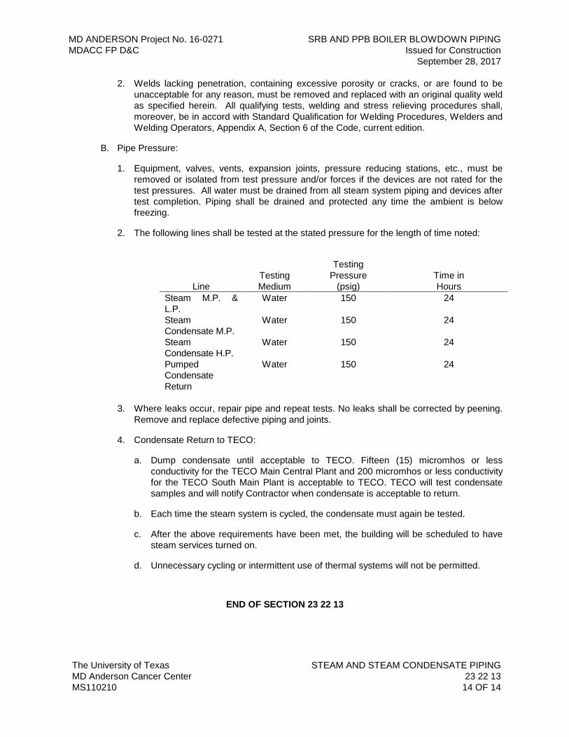
MD ANDERSON Project No. 16-0271 SRB AND PPB BOILER BLOWDOWN PIPING MDACC FP D&C Issued for Construction September 28, 2017
The University of Texas STEAM AND STEAM CONDENSATE PIPING MD Anderson Cancer Center 23 22 13 MS110210 14 OF 14
2. Welds lacking penetration, containing excessive porosity or cracks, or are found to be unacceptable for any reason, must be removed and replaced with an original quality weld as specified herein. All qualifying tests, welding and stress relieving procedures shall, moreover, be in accord with Standard Qualification for Welding Procedures, Welders and Welding Operators, Appendix A, Section 6 of the Code, current edition.
B. Pipe Pressure:
1. Equipment, valves, vents, expansion joints, pressure reducing stations, etc., must be removed or isolated from test pressure and/or forces if the devices are not rated for the test pressures. All water must be drained from all steam system piping and devices after test completion. Piping shall be drained and protected any time the ambient is below freezing.
2. The following lines shall be tested at the stated pressure for the length of time noted:
Line
Testing Medium
Testing Pressure
(psig)
Time in Hours
Steam M.P. & L.P.
Water 150 24
Steam Condensate M.P.
Water 150 24
Steam Condensate H.P.
Water 150 24
Pumped Condensate Return
Water 150 24
3. Where leaks occur, repair pipe and repeat tests. No leaks shall be corrected by peening.
Remove and replace defective piping and joints.
4. Condensate Return to TECO:
a. Dump condensate until acceptable to TECO. Fifteen (15) micromhos or less conductivity for the TECO Main Central Plant and 200 micromhos or less conductivity for the TECO South Main Plant is acceptable to TECO. TECO will test condensate samples and will notify Contractor when condensate is acceptable to return.
b. Each time the steam system is cycled, the condensate must again be tested.
c. After the above requirements have been met, the building will be scheduled to have steam services turned on.
d. Unnecessary cycling or intermittent use of thermal systems will not be permitted.
END OF SECTION 23 22 13
MD ANDERSON Project No. 16-0271 SRB AND PPB BOILER BLOWDOWN PIPING MDACC FP D&C Issued for Construction September 28, 2017
The University of Texas STEAM AND STEAM CONDENSATE SPECIALTIES MD Anderson Cancer Center 23 22 30 MS011509 1 OF 5
SECTION 23 22 30 – STEAM AND STEAM CONDENSATE SPECIALTIES
PART 1 - GENERAL
1.01 RELATED DOCUMENTS
A. Drawings and general provisions of the Contract, including General and Supplementary Conditions and Division 01 Specification Sections, apply to this Section.
B. Specifications throughout all Divisions of the Project Manual are directly applicable to this Section, and this Section is directly applicable to them.
1.02 SUMMARY
A. Perform all Work required to provide and install the following steam specialties indicated by the Contract Documents with supplementary items necessary for their proper installation.
1. Steam relief valves.
2. Steam safety valve discharge elbows.
3. Automatic air vents.
4. Gauges and gauge connections.
5. Thermometer and thermometer wells.
1.03 REFERENCE STANDARDS
A. The latest published edition of a reference shall be applicable to this Project unless identified by a specific edition date.
B. All reference amendments adopted prior to the effective date of this Contract shall be applicable to this Project.
C. All materials, installation and workmanship shall comply with the applicable requirements and standards addressed within the following references:
1. ASTM A105 - Forgings, Carbon Steel, for Piping Components.
2. ASTM A216 - Steel Casings, Carbon, Suitable for Fusion Welding, for High Temperature Service.
3. ASTM A395 - Ferritic Ductile Iron Pressure-Retaining Castings for Use at Elevated Temperatures.
4. ASME B31.9 - Building Services Piping.
1.04 QUALITY ASSURANCE
A. All specialties of the same type shall be provided from the same manufacturer.
B. Manufacturer’s name and pressure rating marked on body of each device.
MD ANDERSON Project No. 16-0271 SRB AND PPB BOILER BLOWDOWN PIPING MDACC FP D&C Issued for Construction September 28, 2017
The University of Texas STEAM AND STEAM CONDENSATE SPECIALTIES MD Anderson Cancer Center 23 22 30 MS011509 2 OF 5
1.05 SUBMITTALS
A. Product Data:
1. Submit Shop Drawings, wiring diagrams and product data on all steam specialties.
B. Record Documents:
1. Shop Drawing submittal of traps shall contain an itemized list with a tabulation of the load, trap type and trap size.
PART 2 - PRODUCTS
2.01 GENERAL
A. All materials shall meet or exceed all applicable referenced standards, federal, state and local requirements, and conform to codes and ordinances of authorities having jurisdiction.
2.02 MANUFACTURERS
A. Automatic Air Vents:
1. Spirax Sarco 13W
2. Spence Engineering.
B. Sediment Strainers:
1. Muller Steam Specialty.
2. Keckley.
3. Spirax Sarco
C. Gauges:
1. Ashcroft No. 1279-R Duragauge.
D. Thermometer and Wells:
1. Weksler Industrial Thermometers.
2. Ashcroft 1279-R.
3. Conbraco 20-150.
2.03 SEDIMENT STRAINERS
A. Sediment strainers in high pressure steam piping shall be cast steel and shall be suitable for working steam pressures as high as 300 pounds per square inch and temperatures not in excess of 750 degrees F.
B. For pipe sizes 2-1/2 inches and larger, flanged pattern sediment strainers shall be used. For pipe smaller than 2-1/2 inches, screwed pattern shall be used.
MD ANDERSON Project No. 16-0271 SRB AND PPB BOILER BLOWDOWN PIPING MDACC FP D&C Issued for Construction September 28, 2017
The University of Texas STEAM AND STEAM CONDENSATE SPECIALTIES MD Anderson Cancer Center 23 22 30 MS011509 3 OF 5
C. The flanges of flanged strainers shall be dimensioned, faced, drilled and spot faced to conform to the 300-pound American Standard for Steel Pipe Flanges and Flanged Fittings (B16E-1939).
D. Strainers in low and medium pressure steam piping systems 2-1/2 inches and larger shall be flanged iron body strainers having bolted covers. These strainers shall be suitable for operating pressures as high as 125 psig.
E. Sediment strainers in low and medium pressure steam piping systems 2 inches and smaller shall be arranged for screwed pipe connections.
2.04 GAUGES AND GAUGE CONNECTIONS
A. Pressure gauges for interior steam systems shall be 4-1/2 inches with back connection when used on a panel; otherwise they shall have bottom connections. Each gauge shall be provided with Ashcroft carbon steel needle valve and a siphon rated for the steam pressure and temperature. The arrangement of the mechanisms shall conform to pressure ranges and details shown on the Drawings.
B. The dial graduation shall be 1.5 times the highest working pressure of the steam that the gauge is serving.
2.05 THERMOMETER AND THERMOMETER WELLS
A. Furnish and install thermometers of not less than 9 inch scale complete with brass separable sockets with extension neck to allow for insulation of piping. These thermometers shall be mercury red reading type in one piece glass tubes extending from top of scale to sensor, and shall be located so that they may be easily read. Field adjustable angle thermometers are acceptable.
B. Thermometers shall be provided with range of 0 to 220 degrees F at hot water heat exchangers. The sensing element of the thermometer shall be at least one inch into the pipe.
C. Thermometer test wells shall be ¾ inch Weksler thermal wells, brass with stem of minimum length to extend beyond the mid-diameter of the pipe, 2-½ inch extension neck and brass screw plug. Wells shall be suitable for use of industrial type thermometers.
D. Indicating thermometers shall be Weksler industrial thermometers having stainless steel separable sockets and scales of the range suitable for steam pressures indicated on flow sheets.
PART 3 - EXECUTION
3.01 INSTALLATION
A. Installation shall meet or exceed all applicable federal, state and local requirements, referenced standards and conform to codes and ordinances of authorities having jurisdiction.
B. Install specialties in accordance with manufacturer’s instructions.
MD ANDERSON Project No. 16-0271 SRB AND PPB BOILER BLOWDOWN PIPING MDACC FP D&C Issued for Construction September 28, 2017
The University of Texas STEAM AND STEAM CONDENSATE SPECIALTIES MD Anderson Cancer Center 23 22 30 MS011509 4 OF 5
C. Install float and thermostatic traps to drain condensate from unit heaters, converters, heating coils, steam separators, flash tanks, steam jacketed equipment and direct steam injected equipment.
D. Rate relief valves for pressure upstream of pressure reducing station, for full operating capacity. Set relief at maximum 20 percent above reduced pressure.
E. Terminate relief valves to outdoors. Provide drip pan elbow with drain connection to nearest floor drain.
F. When several relief valve vents are connected to a common header, header cross sectional area shall equal sum of individual vent outlet areas.
G. Steam Safety Valve Discharge Elbows:
1. All vent lines from safety valves shall be provided with safety valve discharge elbows at the point at which such lines rise to an elevation higher than that of the safety valve. The nature and design of the piping systems involved shall effectively drain all condensate from the discharge side of all relief valves. No force shall be exerted on the safety valve by the discharge piping.
2. Provide temperature sensor mounted in steam safety valve piping in close proximity to steam pressure relief valve. Coordinate with Division 25 such that an alarm is initiated at the BAS upon a rise in temperature.
H. Sediment Strainers:
1. Each drip trap assembly, each control valve, for steam and each pressure reducing valve assembly regardless of its size shall be preceded by a sediment strainer. The arrangement of these sediment strainers shall be such that the screens may be removed for cleaning with ease through a gasketed plug.
2. Sediment strainers shall be placed in steam piping systems wherever shown on the Drawings and at such other points as may be required for the removal of foreign material from the piping systems.
3. Full sized blow off valves shall be installed on all strainers in steam, condensate, chilled and hot water lines and a drain shall be installed from each valve to the nearest floor drain.
I. Automatic Air Vents:
1. Provide auto air vents with a pressure rating that is equal to system classification but not less than 125 psig. Provide shut-off valve to facilitate maintenance of air vent.
2. Locate all air vents and their discharge lines in accessible locations, preferably clustered.
J. Thermometer and Thermometer Wells:
1. Thermometers shall in all cases be installed upright or at the proper angle to be read while standing on the floor. The wells for thermometers shall be located in vertical pipes where possible. When installed in horizontal pipes, thermometers shall be installed in the side and not on top of the pipe.
MD ANDERSON Project No. 16-0271 SRB AND PPB BOILER BLOWDOWN PIPING MDACC FP D&C Issued for Construction September 28, 2017
The University of Texas STEAM AND STEAM CONDENSATE SPECIALTIES MD Anderson Cancer Center 23 22 30 MS011509 5 OF 5
2. Thermometer wells and thermometers shall be located where noted on the Drawings and where called for in other Specification Sections. Thermometer test wells shall only be installed in a vertical position in horizontal lines and at 45 degrees in vertical lines to hold a fluid in the well.
END OF SECTION 23 22 30