Embed Size (px)
Citation preview
BuildingName The Description of the Project P00000000 0000
DOCUMENTS SPECIFICATION DIVISION 23
NUMBER SECTION DESCRIPTION
DIVISION 23 HEATING, VENTILATING AND AIR CONDITIONING (HVAC) SECTION 230905 - MECHANICAL SYSTEMS CONTROLS (HOSPITAL PROJECTS)
END OF CONTENTS TABLE
_______________________________________ ARCHITECTURE, ENGINEERING AND CONSTRUCTION
ARCHITECTURE & ENGINEERING 326 East Hoover, Mail Stop B
Ann Arbor, MI 48109-1002 Phone: 734-764-3414
Fax: 734-936-3334

BuildingName The Description of the Project
P00000000 0000 Issued for:_(FILL _IN)BID 230905 - - 1
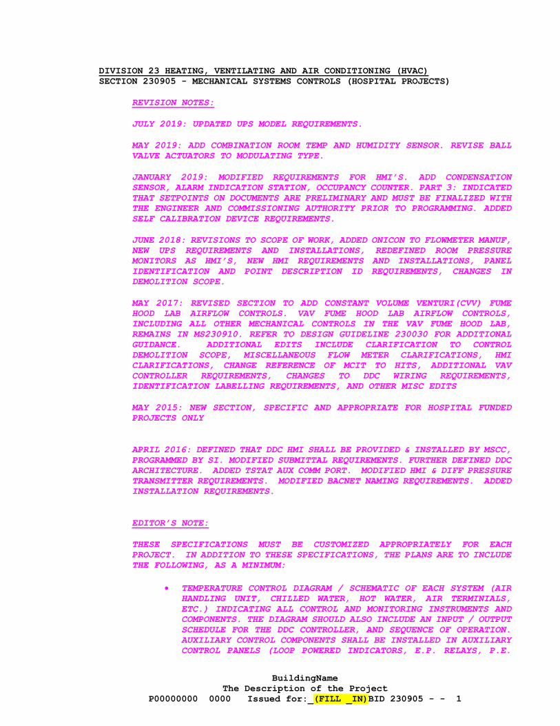
DIVISION 23 HEATING, VENTILATING AND AIR CONDITIONING (HVAC) SECTION 230905 - MECHANICAL SYSTEMS CONTROLS (HOSPITAL PROJECTS)
REVISION NOTES:
JULY 2019: UPDATED UPS MODEL REQUIREMENTS.
MAY 2019: ADD COMBINATION ROOM TEMP AND HUMIDITY SENSOR. REVISE BALL VALVE ACTUATORS TO MODULATING TYPE.
JANUARY 2019: MODIFIED REQUIREMENTS FOR HMI’S. ADD CONDENSATION SENSOR, ALARM INDICATION STATION, OCCUPANCY COUNTER. PART 3: INDICATED THAT SETPOINTS ON DOCUMENTS ARE PRELIMINARY AND MUST BE FINALIZED WITH THE ENGINEER AND COMMISSIONING AUTHORITY PRIOR TO PROGRAMMING. ADDED SELF CALIBRATION DEVICE REQUIREMENTS.
JUNE 2018: REVISIONS TO SCOPE OF WORK, ADDED ONICON TO FLOWMETER MANUF, NEW UPS REQUIREMENTS AND INSTALLATIONS, REDEFINED ROOM PRESSURE MONITORS AS HMI’S, NEW HMI REQUIREMENTS AND INSTALLATIONS, PANEL IDENTIFICATION AND POINT DESCRIPTION ID REQUIREMENTS, CHANGES IN DEMOLITION SCOPE.
MAY 2017: REVISED SECTION TO ADD CONSTANT VOLUME VENTURI(CVV) FUME HOOD LAB AIRFLOW CONTROLS. VAV FUME HOOD LAB AIRFLOW CONTROLS, INCLUDING ALL OTHER MECHANICAL CONTROLS IN THE VAV FUME HOOD LAB, REMAINS IN MS230910. REFER TO DESIGN GUIDELINE 230030 FOR ADDITIONAL GUIDANCE. ADDITIONAL EDITS INCLUDE CLARIFICATION TO CONTROL DEMOLITION SCOPE, MISCELLANEOUS FLOW METER CLARIFICATIONS, HMI CLARIFICATIONS, CHANGE REFERENCE OF MCIT TO HITS, ADDITIONAL VAV CONTROLLER REQUIREMENTS, CHANGES TO DDC WIRING REQUIREMENTS, IDENTIFICATION LABELLING REQUIREMENTS, AND OTHER MISC EDITS
MAY 2015: NEW SECTION, SPECIFIC AND APPROPRIATE FOR HOSPITAL FUNDED PROJECTS ONLY
APRIL 2016: DEFINED THAT DDC HMI SHALL BE PROVIDED & INSTALLED BY MSCC, PROGRAMMED BY SI. MODIFIED SUBMITTAL REQUIREMENTS. FURTHER DEFINED DDC ARCHITECTURE. ADDED TSTAT AUX COMM PORT. MODIFIED HMI & DIFF PRESSURE TRANSMITTER REQUIREMENTS. MODIFIED BACNET NAMING REQUIREMENTS. ADDED INSTALLATION REQUIREMENTS.
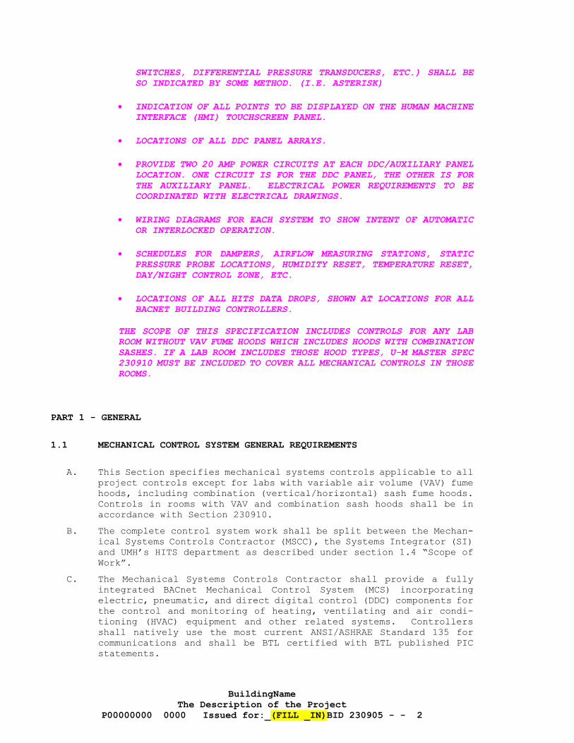
EDITOR’S NOTE:
THESE SPECIFICATIONS MUST BE CUSTOMIZED APPROPRIATELY FOR EACH PROJECT. IN ADDITION TO THESE SPECIFICATIONS, THE PLANS ARE TO INCLUDE THE FOLLOWING, AS A MINIMUM:
• TEMPERATURE CONTROL DIAGRAM / SCHEMATIC OF EACH SYSTEM (AIR HANDLING UNIT, CHILLED WATER, HOT WATER, AIR TERMINIALS, ETC.) INDICATING ALL CONTROL AND MONITORING INSTRUMENTS AND COMPONENTS. THE DIAGRAM SHOULD ALSO INCLUDE AN INPUT / OUTPUT SCHEDULE FOR THE DDC CONTROLLER, AND SEQUENCE OF OPERATION. AUXILIARY CONTROL COMPONENTS SHALL BE INSTALLED IN AUXILIARY CONTROL PANELS (LOOP POWERED INDICATORS, E.P. RELAYS, P.E.
BuildingName The Description of the Project
P00000000 0000 Issued for:_(FILL _IN)BID 230905 - - 2
SWITCHES, DIFFERENTIAL PRESSURE TRANSDUCERS, ETC.) SHALL BE SO INDICATED BY SOME METHOD. (I.E. ASTERISK)
• INDICATION OF ALL POINTS TO BE DISPLAYED ON THE HUMAN MACHINE INTERFACE (HMI) TOUCHSCREEN PANEL.
• LOCATIONS OF ALL DDC PANEL ARRAYS.
• PROVIDE TWO 20 AMP POWER CIRCUITS AT EACH DDC/AUXILIARY PANEL LOCATION. ONE CIRCUIT IS FOR THE DDC PANEL, THE OTHER IS FOR THE AUXILIARY PANEL. ELECTRICAL POWER REQUIREMENTS TO BE COORDINATED WITH ELECTRICAL DRAWINGS.
• WIRING DIAGRAMS FOR EACH SYSTEM TO SHOW INTENT OF AUTOMATIC OR INTERLOCKED OPERATION.
• SCHEDULES FOR DAMPERS, AIRFLOW MEASURING STATIONS, STATIC PRESSURE PROBE LOCATIONS, HUMIDITY RESET, TEMPERATURE RESET, DAY/NIGHT CONTROL ZONE, ETC.
• LOCATIONS OF ALL HITS DATA DROPS, SHOWN AT LOCATIONS FOR ALL BACNET BUILDING CONTROLLERS.
THE SCOPE OF THIS SPECIFICATION INCLUDES CONTROLS FOR ANY LAB ROOM WITHOUT VAV FUME HOODS WHICH INCLUDES HOODS WITH COMBINATION SASHES. IF A LAB ROOM INCLUDES THOSE HOOD TYPES, U-M MASTER SPEC 230910 MUST BE INCLUDED TO COVER ALL MECHANICAL CONTROLS IN THOSE ROOMS.
PART 1 - GENERAL
1.1 MECHANICAL CONTROL SYSTEM GENERAL REQUIREMENTS
A. This Section specifies mechanical systems controls applicable to all project controls except for labs with variable air volume (VAV) fume hoods, including combination (vertical/horizontal) sash fume hoods. Controls in rooms with VAV and combination sash hoods shall be in accordance with Section 230910.
B. The complete control system work shall be split between the Mechan-ical Systems Controls Contractor (MSCC), the Systems Integrator (SI) and UMH’s HITS department as described under section 1.4 “Scope of Work”.
C. The Mechanical Systems Controls Contractor shall provide a fully integrated BACnet Mechanical Control System (MCS) incorporating electric, pneumatic, and direct digital control (DDC) components for the control and monitoring of heating, ventilating and air condi-tioning (HVAC) equipment and other related systems. Controllers shall natively use the most current ANSI/ASHRAE Standard 135 for communications and shall be BTL certified with BTL published PIC statements.
BuildingName The Description of the Project
P00000000 0000 Issued for:_(FILL _IN)BID 230905 - - 3
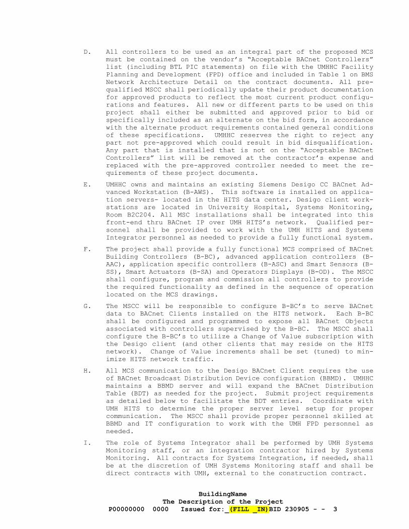
D. All controllers to be used as an integral part of the proposed MCS must be contained on the vendor’s “Acceptable BACnet Controllers” list (including BTL PIC statements) on file with the UMHHC Facility Planning and Development (FPD) office and included in Table 1 on BMS Network Architecture Detail on the contract documents. All pre-qualified MSCC shall periodically update their product documentation for approved products to reflect the most current product configu-rations and features. All new or different parts to be used on this project shall either be submitted and approved prior to bid or specifically included as an alternate on the bid form, in accordance with the alternate product requirements contained general conditions of these specifications. UMHHC reserves the right to reject any part not pre-approved which could result in bid disqualification. Any part that is installed that is not on the “Acceptable BACnet Controllers” list will be removed at the contractor’s expense and replaced with the pre-approved controller needed to meet the re-quirements of these project documents.
E. UMHHC owns and maintains an existing Siemens Desigo CC BACnet Ad-vanced Workstation (B-AWS). This software is installed on applica-tion servers- located in the HITS data center. Desigo client work-stations are located in University Hospital, Systems Monitoring, Room B2C204. All MSC installations shall be integrated into this front-end thru BACnet IP over UMH HITS’s network. Qualified per-sonnel shall be provided to work with the UMH HITS and Systems Integrator personnel as needed to provide a fully functional system.
F. The project shall provide a fully functional MCS comprised of BACnet Building Controllers (B-BC), advanced application controllers (B-AAC), application specific controllers (B-ASC) and Smart Sensors (B-SS), Smart Actuators (B-SA) and Operators Displays (B-OD). The MSCC shall configure, program and commission all controllers to provide the required functionality as defined in the sequence of operation located on the MCS drawings.
G. The MSCC will be responsible to configure B-BC’s to serve BACnet data to BACnet Clients installed on the HITS network. Each B-BC shall be configured and programmed to expose all BACnet Objects associated with controllers supervised by the B-BC. The MSCC shall configure the B-BC’s to utilize a Change of Value subscription with the Desigo client (and other clients that may reside on the HITS network). Change of Value increments shall be set (tuned) to min-imize HITS network traffic.
H. All MCS communication to the Desigo BACnet Client requires the use of BACnet Broadcast Distribution Device configuration (BBMD). UMHHC maintains a BBMD server and will expand the BACnet Distribution Table (BDT) as needed for the project. Submit project requirements as detailed below to facilitate the BDT entries. Coordinate with UMH HITS to determine the proper server level setup for proper communication. The MSCC shall provide proper personnel skilled at BBMD and IT configuration to work with the UMH FPD personnel as needed.
I. The role of Systems Integrator shall be performed by UMH Systems Monitoring staff, or an integration contractor hired by Systems Monitoring. All contracts for Systems Integration, if needed, shall be at the discretion of UMH Systems Monitoring staff and shall be direct contracts with UMH, external to the construction contract.
BuildingName The Description of the Project
P00000000 0000 Issued for:_(FILL _IN)BID 230905 - - 4
1.2 DEFINITIONS
A. BMS: Building Management System
B. BTL: BACnet Testing Labs http://www.bacnetinternational.net/btl/
C. B-AAC: BACnet Advanced Application Controller
D. B-ASC: BACnet Application Specific Controller
E. B-AWS: BACnet Advanced Workstation
F. B-OD: BACnet Operators Device
G. B-BC: BACnet Building Controller
H. B-SA: BACnet Smart Actuator
I. B-SS: BACnet Smart Sensor
J. BBMD: BACnet Broadcast Management Device
K. BDT: BACnet Distribution Table
L. DDC: Direct Digital Control
M. FLN: Field Level Network
N. FPD: Facilities Planning and Development (Hospital)
O. HITS: Health Information Technology & Services
P. HMI: Human Machine Interface Panel
Q. MSCC: Mechanical Systems Controls Contractor
R. MCS: Mechanical Control System
S. SI: Systems Integrator
T. Systems Monitoring: UMHHC department responsible for owning & oper-ating the hospital’s Building Management System
U. TC: Temperature Controls
V. UMHHC: University of Michigan Hospitals and Health Centers
1.3 RELATED DOCUMENTS
A. Drawings and general provisions of the Contract, Standard General and Supplementary General Conditions, Division 1 Specification Sec-tions, and other applicable Specification Sections including the Related Sections listed below, apply to this Section.
B. Related Sections
1. Division 26: Electrical 2. 220523 Valves 3. 233600 Air Terminal Units 4. 230910 VAV Fume Hood Laboratory Air Flow Controls
BuildingName The Description of the Project
P00000000 0000 Issued for:_(FILL _IN)BID 230905 - - 5
1.4 SCOPE OF WORK
A. The complete control system work shall be split between the Mechan-ical Systems Controls Contractor, the Systems Integrator and UMH’s HITS department as described below and under section 1.5 “Related Work by Others”. As it relates to the extent of responsibility for work within this specification section, "provide" shall mean the identified party both furnishes and installs such item(s). "Fur-nish" shall mean the identified party furnishes the item for in-stallation by others.
B. The Mechanical Systems Controls Contractor shall be a direct Sub-contractor to the Contractor.
SPEC WRITER NOTES: EDIT SCOPE OF WORK TO SUIT THE SPECIFIC NEEDS OF THE PROJECT
C. Summary of work by the Mechanical Systems Controls Contractor shall include, but not be limited to:
1. Providing a native BACnet-based (latest version of ANSI/ ASHRAE 135) MCS consisting of programmable and application specific DDC controllers, electronic sensors, pneumatic actuators, elec-tronic to pneumatic transducers, relays, switches, control pan-els, power supplies, twisted shielded pair (TSP)network cabling and all associated control wiring (excluding Ethernet network wiring) and low voltage conduit systems.
2. Providing control panels for all DDC controllers and an auxil-iary control panel for all ancillary control devices (electric and pneumatic relays, EP switches, contactors, etc.)
3. Provide application specific controllers (B-ACS) or advanced application controllers (B-AAC) for terminal units (VAV, Dual Duct, Fan Coil Units etc.) including associated room tempera-ture sensors, room temperature sensors with LED display, room temperature sensors with bias adjustment, and CO2 sensors.
4. Create BACnet object names and tags according to UMHHC’s point naming standard outlined at in Section 3 – Execution.
SPEC WRITER NOTES: DRAWINGS SHOULD INDICATE LOCATION AND TYPE OF COMMUNICATION CONNECTION SHOWING NECESSARY CONDUIT TO THAT LOCATION (NEAREST DDC PANEL FOR EXISTING BUILDINGS OR NEAREST HITS CLOSET FOR NEW BUILDINGS). 5. Final connection of control panels to the HITS Network from
patch panels to the B-BC to permit communication between B-BC’s to the existing Building Management System (BMS) server(s) via BACnet/IP. MSCC shall provide and install data connection raceway from panel to facility cable tray. UMHHC HITS depart-ment will provide network drops using biscuit jacks inside the control panels to patch panels installed in HITS Telecommuni-cation Rooms. MSCC shall provide and install MS/TP communica-tion trunk for BACnet AAC’s, ASC’s, SA’s and SS’s.
6. For UM Utility’s energy metering, install UM furnished data acquisition panel for utility metering. Provide Ethernet con-nection of Utility Meters to host computer. MSCC shall provide and install data connection raceway from panel to facility cable tray. Provide wiring from meters and transmitters to utility data acquisition panels. Provide communication wiring to utility data acquisition panels. Terminations inside panels by UM Utilities.
BuildingName The Description of the Project
P00000000 0000 Issued for:_(FILL _IN)BID 230905 - - 6
7. Engineering, submittals, as-built drawings, and operation and maintenance manuals.
8. Provide an auxiliary temperature control panel adjacent to each DDC panel. Provide additional auxiliary panels as required to house the required quantity of control components. Small con-trol installations with limited future expansion may be allowed to forego an aux panel and install all devices in a single DDC panel- contact project engineer for approval. Auxiliary panels shall not be smaller than 24"x24", and shall have a 1’ high by minimum 2’ wide (but not less than panel width) contiguous clear area which can be used for future expansion. Provide all wiring between the DDC panel and the auxiliary panel(s).
9. Provide & install all Human Machine Interfaces (HMI’s). Provide all wiring and accessories required to enable HMI to function as specified.
10. Provide and mount all airflow measuring station/ flow meter LCD readout panels on wall adjacent to DDC panels.
11. Provide & install all UPS’s and required enclosures. Provide all interconnecting power wiring between the DDC panel power supply and the UPS panel receptacle.
12. Provide a 6”x 6” wiring trough extending over and between each DDC, auxiliary temperature control, and LPI panel. Provide 1” conduit from trough to cable tray, bonded to tray, for HITS network connection (coordinate routing with HITS).
13. Provide and install all DDC panel and device enclosures. 14. Provide pneumatic thermostats (where applicable), control
valves, dampers, operators, meters, control air tubing, etc. 15. Provide gauges, indicating devices, electric and electronic
control accessories, and other control system devices. 16. Provide setup/ programming, calibration and start-up services
of all DDC and non-DDC temperature control systems. 17. Provide site supervision of temperature control work and coor-
dination with related, pneumatic, electrical, fire alarm work and packaged controls.
18. Provide all control wiring and electrical components necessary for each system to permit automatic or interlocked operation, such as: air cooled condensing units, high level alarm circuits, damper end switches, fuel oil pumping/monitoring systems, chiller control/interface panels, boiler control/interface pan-els, early break contacts on disconnects to VSD's, cooling tower vibration switches, etc.
19. The MSCC shall be responsible for completely removing and de-commissioning all existing control devices, wiring, control-lers, panels, supports, etc that are being affected by the project’s control modifications, including decommissioning any existing DDC control programming on UMH’s Siemens, Honeywell, Johnson Controls, or ASI DDC systems that are from points/ devices/ controllers removed or modified under the scope of the MSCC’s work. The MSCC’s decommissioning work shall include updating the vendor’s engineering database, located on UMH cen-tral servers, from devices removed under the MSCC’s scope of work as well as coordinating removed devices/ points with UMH Systems Monitoring so that the front end can be updated accord-ingly.
20. Re-establish and validate existing DDC controller communication modified by the scope of work.
BuildingName The Description of the Project
P00000000 0000 Issued for:_(FILL _IN)BID 230905 - - 7
21. All other work and components required for complete and opera-tional temperature control systems as specified herein, exclud-ing work specified below in “Related Work by Others” section that is to be provided or furnished by the Systems Integrator.
22. Start-up, calibration, and checkout of sensors, transducers, thermostats, control valves, dampers/damper operators, meters, and all other components provided.
23. Commission all mechanical controls provided. Provide a detailed list of every control point installed to the project Commis-sioning Authority (CxA), and verify proper operation of each component prior to commissioning the controls with the CxA. Include, in checklist format, a detailed procedure to verify all aspects of the controls’ Sequence of Operation.
24. Participation in point-to-point verification with Systems In-tegrator for all control points.
25. Coordination with Systems Integrator, UMHHC’s HITS and Systems Monitoring groups.
26. Training of UMHHC personnel to familiarize operations staff with the configuration and operation of this project’s MCS installations.
SPEC WRITER NOTES: FUME HOOD MONITORS ARE TYPICALLY NOT PROVIDED BY THE MSCC ON UMH PROJECTS, BUT ARE RATHER PROVIDED WITH THE FUME HOOD. FOR RARE OCCASIONS WHERE THE MSCC WILL PROVIDE THE FUME HOOD MONITOR, CHANGE THE FOLLOWING PARAGRAPH FROM HIDDEN TEXT.
27. Provide fume hood monitors except in rooms with VAV hoods, including combination sash fume hoods.
1.5 RELATED WORK BY OTHERS
A. BMS related work by the Systems Integrator:
1. BACnet device and object discovery. 2. BACnet object instantiation (creation of object classes, naming
and location meta data) 3. Generation of Desigo system graphics, alarm summary pages and
point/object trend views. 4. Removal/ decommissioning of all graphics, alarms, trends af-
fected by DDC demolition. 5. Configure all required alarming and point/object trending at
the Desigo CC frontend. 6. Generation of graphics and configuration of HMI at DDC panels. 7. Point-to-point verification with MSCC for all control points.
B. BMS related work by HITS:
1. Providing IP Layer 3 networking for all peer-to-peer communi-cation of DDC Building Controllers, utility acquisition panels and the front-end. The MSCC shall be responsible for coordi-nating implementation of the MCS on the HITS network without disruption.
2. HITS will verify network connectivity and establish a TCP con-nection between the BMS server and the network drop termina-tion.
3. HITS will provide all required patch cables. MSCC shall be responsible for connecting all patch cables at respective con-trollers/ UPS’s.
BuildingName The Description of the Project
P00000000 0000 Issued for:_(FILL _IN)BID 230905 - - 8
C. BMS related work by Systems Monitoring:
1. Management of existing and assignment of new: a. IP addresses b. BACnet Device Instance and Network numbers c. BACnet Broadcast Management Device (BBMD) and Broadcast
Distribution Table (BDT) d. MS/TP MAC Addresses
2. The SI shall be responsible for any changes from removed points, devices & controllers to UMH’s BMS frontend and the engineering database.
D. BMS related work by UM Utilities
1. Provide utility meter data acquisition panels. Panels in-stalled and wired by MSCC. UM Utilities to terminate all I/O wiring and data connections, as well as start-up, configure and commission the panel.
1.6 ACCEPTABLE MECHANICAL SYSTEMS CONTROLS CONTRACTORS
A. The following MSCCs are acceptable for the furnishing and installa-tion of pneumatic, electric and DDC components as specified in this section:
1. Siemens Building Technologies 2. Honeywell, Inc. 3. Fontanesi & Kann (ASI Controls)
EDITOR: CONTACT THE UM DESIGN MANAGER TO DETERMINE WHICH OF THE ABOVE CONTROLS INSTALLATION CONTRACTORS ARE TO BE LISTED AS ACCEPTABLE FOR YOUR SPECIFIC PROJECT.
1.7 QUALITY ASSURANCE
A. Manufacturers and Products: The products and manufacturers specified in this Section establish the standard of quality for the Work. Subject to compliance with all requirements, provide specified prod-ucts from the manufacturers named in Part 2.
B. Reference Standards: Products in this section shall be built, tested, and installed in compliance with the specified quality as-surance standards; latest editions, unless noted otherwise.
1. Electrical Standards: Provide electrical products that have been tested, listed and labeled by UL and comply with NEMA standards as well as NFPA 70 (National Electric Code).
2. NEMA Compliance: Comply with NEMA standards pertaining to components and devices for electrical control systems.
3. NFPA Compliance: Comply with NFPA 90A "Standard for the In-stallation of Air Conditioning and Ventilating Systems" where applicable to controls and control sequences.
4. Install all BMS components, panels, and wiring in compliance with NEC and all local electrical codes.
5. DDC devices shall use the latest version of ANSI/ASHRAE Stand-ard 135 “BACnet- Building Automation and Control Networking Protocol” standard for communications and have passed BTL cer-tification as available.
BuildingName The Description of the Project
P00000000 0000 Issued for:_(FILL _IN)BID 230905 - - 9
6. UL Compliance: DDC Controllers for this project shall comply with UL916 Standard for Energy Management Equipment. DDC Con-trollers associated with equipment utilized in a smoke control application shall also comply with UUKL-UL 864 “Standard for Control Units and Accessories for Fire Alarm Systems”.
7. National Institute of Standards and Technology (NIST), NIST IR 6392 Annex B: Profiles of Standard BACnet Devices.
8. Electronics Industries Association (EIA) a. EIA-232: Interface Between Data Terminal Equipment and
Data Circuit-Terminating Equipment Employing Serial Binary Data Interchange
b. EIA-485: Standard for Electrical Characteristics of Gen-erator and Receivers for Use in Balanced Digital Multi-Point System
1.8 COORDINATION
A. Coordinate with UMHHC’s HITS and Systems Monitoring groups as spec-ified in this section. All correspondence with Systems Monitoring shall be directed to Byron Anderson, [email protected] , (734) 232-0126.
B. Coordinate with Systems Integrator. All correspondence with Systems Integrator shall be directed to Byron Anderson, [email protected], (734) 232-0126. See section 3.10 for more details on coordination requirements with the SI.
C. All correspondence with HITS, Systems Monitoring & SI shall be co-ordinated thru the owner’s project manager.
D. Ensure installation of components is complementary to installation of similar components in other systems.
E. Coordinate installation of system components with installation of other mechanical system equipment.
F. Coordinate control wiring requirements with mechanical equipment manufacturers.
SPEC WRITER NOTES: FUME HOOD MONITORS ARE TYPICALLY NOT PROVIDED BY THE MSCC ON UMH PROJECTS, BUT ARE RATHER PROVIDED WITH THE FUME HOOD. FOR RARE OCCASIONS WHERE THE MSCC WILL PROVIDE THE FUME HOOD MONITOR, CHANGE THE FOLLOWING PARAGRAPH FROM HIDDEN TEXT.
G. Coordinate with laboratory equipment suppliers (constant flow fume hoods, etc.) regarding dimensions and mounting location for alarm monitors and assure proper accommodation is made for the installation of other devices related to laboratory airflow controls.
1.9 SUBMITTALS
A. Prior to submitting shop drawings to the AE of record, the MSCC shall request BMS address assignments from UMH Systems Monitoring, including:
1. IP addresses for new devices and the necessary IP addresses of other BACnet IP devices (for the BACnet Broadcast Distribution Table)
2. BACnet Device Instance and Network numbers
BuildingName The Description of the Project
P00000000 0000 Issued for:_(FILL _IN)BID 230905 - - 10
3. BACnet BBMD (when required) and BDT 4. MS/TP MAC addresses MSCC shall utilize the BMS Addressing Template available through the URL https://umich.box.com/BMS-Addressing-Template for all de-vices needing BMS addressing. MSCC shall submit initial shop drawings to the Systems Integrator for coordination. MSCC shall also submit the approved submittal package to the Systems Integrator before construction begins so that front-end integration work at the central BMS server(s) may be performed while the Mechanical Controls System is being con-structed.
B. Submit shop drawings to the project AE of record for their review and approval.
C. No work shall be done until the final submittals are approved by project AE.
D. Shop drawings shall contain, as a minimum, the following:
1. UMH BMS Addressing Template pre-filled in with all project specific DDC devices needing BMS addressing assignments.
2. Schematic diagrams of all systems being controlled and/or mon-itored indicating all DDC points or BACnet objects, BACnet instance numbers, IP addresses, MS/TP MAC addresses, object names/numbers (using UMHHC standard point naming conventions), sensors, relays, controllers, valves, dampers, complete control wiring schematics (including starter, VSD, DX system, etc. wir-ing diagrams), pneumatic tubing, DDC panel maps, etc.
3. Clearly indicate if DDC points are analog inputs (AI), analog outputs (AO), digital inputs (DI) or digital outputs (DO).
4. Wiring of each point to the DDC panels, including terminal block numbers.
5. Layout of all auxiliary devices and panels, and wiring of re-lays, contacts, etc. Include terminal block numbers at all control panels, at all mechanical equipment, and at all control devices.
6. Complete Sequence of Operation for each system being con-trolled, including set points, etc. in written (text) format. Identify each piece of equipment that the sequence of operation applies to utilizing the equipment tags from the engineer’s equipment schedules.
7. Schematic diagram of the total DDC system layout, including all panels, trunk cables, peripheral devices, locations, etc.
8. Pneumatic compressed air supply equipment, risers, and major tubing runs.
9. Complete bill of materials to identify and quantify all devices and controllers.
10. Protocol Implementation Conformance Statements (PICS) for all native BACnet controllers and BACnet IP routers.
11. Location/ identification of BBMD including configuration de-tails.
12. A schedule of all nameplates and associated wording. 13. An index of sheets for ease of access. 14. Wiring diagrams and locations of power supplies. 15. Additional submittal items required for any room designated as
a lab:
BuildingName The Description of the Project
P00000000 0000 Issued for:_(FILL _IN)BID 230905 - - 11
a. Equipment schedule for each room or zone, with the fol-lowing information: 1) Equipment tag, room served, occupied/unoccupied min.,
max., and offset CFM; lab subnet description, name, and network address; network and power trunk identi-fier.
2) Model number of each control component. 3) Function of each terminal airflow unit and control
component
E. Submit, as a minimum, the following design data schedules indicat-ing:
1. Airflow Measuring Probes: a. Device tag. b. Equipment served/function. c. Model number. d. Size, type, and location. e. Station area in square feet. f. Max/Min Range. g. Magnehelic scale range. h. Velocity pressure range.
2. Air and water pressure sensors: a. Device tag. b. Equipment served/function. c. Model number. d. Size, type, and location. e. Max/Min Range.
3. Control Dampers: a. Damper tag. b. Equipment served/function. c. Model number. d. Blade configuration and orientation. e. Size in width, height, and blade width. f. Pressure drop. g. Type of seals (blade and edge). h. Normal position. i. Size, quantity, type, and model number of actuators. j. Method of actuator mounting and actuation.
4. Control Valves: a. Valve tag. b. Equipment served/function. c. Valve flow rate (GPM). d. Line size. e. Specified valve pressure drop (ft. head). f. Valve size. g. Valve Cv. h. Actual valve pressure drop (ft. head). i. Valve normal position. j. Valve spring range. k. Valve shut-off rating (ft. head). l. Valve body pressure/temperature rating. m. Valve type/model number. n. Actuator type/model number.
5. DDC Controllers: a. Device tag. b. Equipment served/function. c. Model number and application code.
BuildingName The Description of the Project
P00000000 0000 Issued for:_(FILL _IN)BID 230905 - - 12
d. Associated sensor location/tag. e. Size, control values, etc.
F. Submittal Requirements
1. Shop drawings shall be 8-1/2” x 11” and 11" x 17" size. 2. All schematics and drawings shall be done on CAD. The elec-
tronic files shall be in the latest version of AutoCAD (or as noted otherwise)
3. Product data shall include description and complete engineering data for each control system component. Data sheets shall be organized behind sheet tabs. Each sheet tab shall indicate the category or component name (i.e. valves, dampers, relay & switches, thermostats, temperature transmitters, pressure transmitters, air flow stations, controllers, etc.).
4. Since many items are interrelated and should be checked con-currently, all of the MSCC's DDC related shop drawings shall be submitted at one time. No consideration will be given to partial submittals, except valve and damper submittals on ap-proval only. Any partial submittals must be included in the complete submittal package.
G. Project Record Documents
1. Submit Project Record Documents to Systems Monitoring at the time of substantial completion.
2. Revise shop drawings to reflect actual installation and oper-ating sequences and provide final electronic files in PDF.
3. PDFs shall contain the following files in the indicated format: a. As-built drawings in PDF format (separate file for each
system’s related drawings/sheets). b. Sequences of operation in PDF. Provide separate files for
each system’s sequence of operation. c. Product data and catalog specification sheets in PDF for-
mat (separate file for each product). 4. List of all BACnet IP and MSTP devices installed with their
network IP addresses, BACnet Device Instance numbers and asso-ciated BACnet network numbers. MSCC shall be responsible for uploading the completed, as-builted BMS Addressing Template required under section 1.9.A upon project substantial comple-tion.
5. All files shall be dated and shall contain the UMHHC project RTN number and UM AEC P100 number when applicable.
H. Operation and Maintenance Manuals
1. The MSCC shall provide the specified number of copies of com-plete operation and maintenance instructions for all system components furnished.
2. Include hard-copies of all Project Record Documents described above in paragraph G.
3. Indicate final set points, settings, and adjustments of all components.
4. Include project specific catalog cuts and data sheets indicat-ing installation, operation, maintenance, repair, wiring dia-grams, calibration, calibration tolerances, inspection period, cleaning methods and cleaning materials for all components.
I. Posted Operating Instructions
BuildingName The Description of the Project
P00000000 0000 Issued for:_(FILL _IN)BID 230905 - - 13
1. Provide panel related as-built documents in protective binder or clear plastic display envelope for each control panel. These instructions shall include such items as as-built control dia-grams and sequences of operation, simplified narrative instruc-tions and materials necessary to aid in the operation of the equipment at the local control panels.
1.10 DELIVERY, STORAGE AND HANDLING
A. Shipping and storage protection shall be provided by manufacturer to insure that the interior and exterior of components are completely protected from damage, dirt or weather. Components shall be contin-uously covered with plastic or other durable means, until just prior to installation. Maintain protection after installation to protect against on-going construction activities.
1.11 WARRANTY
A. The Building Management System shall be guaranteed for a period of one year after final approval has been granted by the Owner and the project Architect/Engineer. The warranty shall be provided for a completely installed system, including all components, parts and assemblies. The warranty shall cover parts, materials and labor to correct any defects in materials and workmanship.
B. The MSCC shall initiate the warranty period by formally transmitting to the Owner commencement notification of the period for the system and devices accepted.
C. Provide 24 hour per day emergency service during warranty period, with maximum next-day response. Provide phone number(s) for quick assistance by a Service Engineer regarding hardware or software problems.
D. Provide any software or firmware revisions which are released by the DDC system manufacturer during the warranty period, at no additional cost to the Owner. Revisions that require updates at the central BMS server(s) will be coordinated with the SI at no additional cost to the Owner.
E. The MSCC shall provide programming modifications necessary to fine tune equipment sequences during the warranty period, consistent with achieving the sequence of operation and design intent, at no addi-tional cost to the Owner.
PART 2 - PRODUCTS
2.1 ACCEPTABLE PRODUCT MANUFACTURERS
A. All pneumatic devices, valves, damper operators, EP relays, PE switches, low temperature detection thermostats, etc. shall be as manufactured by Honeywell, Johnson Controls or Siemens, unless noted otherwise in following sections. See “Products" for acceptable manufacturers for sensors, etc.
BuildingName The Description of the Project
P00000000 0000 Issued for:_(FILL _IN)BID 230905 - - 14
EDITOR: CONTACT THE UMHHC FPD DESIGN MANAGER TO DETERMINE WHICH OF THE FOLLOWING DDC SYSTEM MANUFACTURERS ARE TO BE LISTED AS ACCEPTABLE FOR THE PROJECT.
B. DDC controllers and related software shall be in accordance with the pre-approved parts list as manufactured by the respective MSCC listed under Part 1- ACCEPTABLE MECHANICAL SYSTEMS CONTROLS CONTRACTORS.
2.2 GENERAL DDC CONTROL ARCHITECTURE
A. BACnet Building Controllers (B-BC) and IP capable Advanced Applica-tion Controller (B-AAC) shall provide IP routing capabilities to allow communication over UMH HITS’s network (layer 3 IP) and between controllers. A secondary field level network (FLN) shall allow data to be exchanged between B-BC’s and Advanced Application Controllers (B-AAC) and Application Specific Controllers (B-ASC) via BACnet MS/TP communication. BACnet objects shall be routed from the new MCS installation to the existing central BMS server(s) that reside on the HITS network. The SI will utilize these BACnet objects to generate system graphics at the existing BMS server(s).
B. The complete Mechanical Control System (MCS) shall consist of the following:
1. Data integration to UMHHC’s existing BACnet AWS servers and operator work stations.
2. Peer-to-peer B-BC’s communicating with other B-BC’s and B-AAC (where IP capable) and UMHHC’s existing BACnet AWS over the HITS layer 3 IP network.
3. Peer-to-peer B-AAC, B-ASC, B-SS, B-SA and B-OD’s communicating with each other over a MS/TP FLN provided by the MSCC.
4. Sensors, transducers, thermostats, actuators, wiring, etc. di-rectly wired to their respective DDC controller for a complete and operational MCS.
C. BACnet Broadcast Management shall be facilitated by one B-BC per IP Subnet and incorporate a BACnet Distribution Table, provided by System’s Monitoring. B-BC’s that handle BBMD’s and I/O functionality shall be properly sized to handle memory & processing requirements.
D. Terminal units (VAV, FCU, etc) that do not need the global command functionality that a B-BC could provide are allowed to be integrated to the Desigo B-AWS via the use of a BACnet IP Router. Router shall convert BACnet MS/TP to BACnet IP and function as a BBMD.
E. The system shall be modular in nature and shall permit expansion of both capacity and functionality through the addition of sensors, actuators, Building Controllers, Advanced Application Specific Con-trollers, Application Specific Controllers, expansion modules and operator devices.
F. System architectural design shall eliminate dependence upon any sin-gle device for control execution. Each DDC controller shall operate independently by performing its own specified control, operator I/O and data collection. The failure of any single component or network connection shall not interrupt the execution of control strategies at other operational devices. Data collection that requires a single mechanism for user notification or viewing is strictly prohibited.
BuildingName The Description of the Project
P00000000 0000 Issued for:_(FILL _IN)BID 230905 - - 15
G. All controllers within a building shall be able to access any data from, or send control commands directly to, any other DDC controller or combination of controllers in the same building without depend-ence upon a central processing device (peer-to-peer).
H. UMH’s HITS Layer 3 Network is the preferred primary network commu-nication means and will be required for communication between all Building Controllers (B-BC), IP capable B-AAC’s and the BMS B-AWS, via BACnet IP. The use of MS/TP communications for interconnecting the said IP capable devices is strictly prohibited. HITS shall provide and install the primary network, based on coordination with the MSCC.
I. The secondary FLN shall utilize the Master-Slave/Token-Passing (MS/TP) protocol, as acknowledged by the ANSI/ASHRAE 135 standard. This secondary network shall be provided and installed by the MSCC. Proprietary RS-485 or equivalent links will not be considered unless otherwise noted. The MS/TP link shall operate at a 38.4 Kbps minimum, and utilize no more than 2 repeaters in any instance. Multi-channel repeaters will not be permitted.
J. All BACnet IP routers connected to the HITS network, whether integral to a controller or not, must support BACnet Broadcast Management Device (BBMD) service. Multi-casting or global broadcasting will not be permitted without the use of a BBMD.
K. FLN data communications media shall be provided by a shielded twisted pair conductor.
L. The FLN shall allow shared point and control information between BACnet DDC controllers. All required MS/TP repeaters, hubs, active links, gateways, etc. and associated power supplies shall be pro-vided as required to provide shared point and control information between DDC controllers. Ethernet IP network devices and path shall be provided by UMH's HITS.
M. Failure of any individual FLN installed BACnet controllers shall not cause the loss of communications between peer controllers.
N. All data transmitted must be positively acknowledged as received or negatively acknowledged as not received. Negative acknowledgments shall cause a retransmission of the data. Network connected devices must send a "Heartbeat" message at a configurable time interval. Lack of a "Heartbeat" message after successive retries shall con-stitute a device failure and shall be recognized as such by the network and be reported as a network alarm at the BMS B-AWS.
O. Error recovery and communication initialization routines shall be resident in each network connected device.
P. UL864 controllers and devices installed for equipment utilized in a smoke control sequence shall not be on the same MS/TP network segment as non-UL864 controllers and devices. These devices shall be on their own MS/TP network segment.
BuildingName The Description of the Project
P00000000 0000 Issued for:_(FILL _IN)BID 230905 - - 16
Q. The MSCC shall provide an IP connected DDC controller in the same room as the equipment it serves, unless the contract documents ex-plicitly direct otherwise. Designs that situate controllers in different rooms or on other floors than the equipment being served (ie remote I/O) shall not be allowed without special permission by FPD Engineer. IP connectivity to every DDC controller is preferred, however in an instance where multiple pieces of equipment are within a common room, a MS/TP bus of up to 5 MS/TP controllers shall be allowed.
1. Exceptions to this are the use of MS/TP connected DDC control-lers for equipment that functions as a system, ie chiller plants utilizing chillers and cooling towers shall utilize an IP con-nected controller in the chiller plant and a MSTP subnetwork to a secondary controller serving the cooling towers on the roof. MS/TP controllers are preferred to remote I/O modules for these types of applications. Use of remote I/O shall not be allowed without special permission by FPD engineer.
SPEC WRITER NOTES: INCLUDE THE FOLLOWING PARAGRAPH “R” FOR ALL INPATIENT I-2 FACILITIES AND ANY OTHER CRITICAL FACILITIES (IE DATA CENTERS, ETC). OTHERWISE DELETE PARAGRAPH “R” BELOW.
R. In general, the MSCC shall provide a fault tolerant BMS architecture such that the loss of a single DDC controller does not inhibit the continued, automatic operation of that utility service (ie chilled water, heating hot water, airflow, etc). BMS architecture does not need to be fully redundant, but rather be capable of continuing to provide a partial capacity of the utility being produced. For example, do not control the entire facility chilled water plant (multiple chillers, pumps and towers) off a single DDC controller. Provide multiple (minimum of two) DDC controllers for all critical, major mechanical systems, including but not limited to:
1. Minimum of two (2) DDC controllers per chilled water plant (chillers, pumps, cooling towers, etc).
2. Minimum of two (2) DDC controllers per heating hot water plant (boilers, heat exchangers, pumps, etc).
3. A maximum of two (2) air handling units (AHU) on a single DDC controller. AHU’s sharing a DDC controller shall not be de-signed as backup for one another, i.e. thru a header system or common SA or RA ductwork.
4. Air handling units (AHU) serving operating rooms (OR’s) are required to utilize a dedicated DDC controller per AHU.
2.3 GENERAL DDC CONTROLLER REQUIREMENTS
A. Stand-alone microprocessor board with ROM and fully custom program-mable RAM, EPROM, and/or EEPROM memory, integral interface equipment and power surge protection. DDC controllers shall be connected di-rectly to sensors, controlled devices and the communication network.
BuildingName The Description of the Project
P00000000 0000 Issued for:_(FILL _IN)BID 230905 - - 17
B. All DDC controllers shall use the latest version of ANSI/ASHRAE Standard 135 BACnet standard for communications, have passed BTL certification as available and be listed as compliant with UL916 Standard for Energy Management Equipment. DDC controllers used in smoke control applications must also be listed as compliant with UL864 Standard for Control Units and Accessories for Fire Alarm Systems.
C. Controllers shall be listed by BACnet Testing Laboratories (BTL) as conforming to the required standard device profile and support all of the minimum required BACnet Interoperability Building Blocks (BIBBs) associated with this device profile.
D. The “Present_Value” property of all analog output and binary output objects shall be writable so that Systems Monitoring personnel have the capability to override all system outputs from the central BMS server(s).
E. Each DDC controller shall support firmware upgrades without the need to change hardware.
F. Each DDC controller shall continuously perform self-diagnostics, communication diagnosis, and diagnosis of all panel components. The DDC controller shall provide both local and remote annunciation of any detected component failures, low battery conditions or repeated failure to establish communication for any system.
G. DDC controller types shall be one of three types, a BACnet Building Controller (B-BC), a BACnet Advanced Application Specific Controller (B-AAC) or a BACnet Application Specific Controllers (B-ASC).
1. Building Controllers (B-BC) shall be used for all major mechan-ical equipment and/or systems (i.e. chilled water, heating hot water, large AHU’s, etc.).
2. Advanced Application Specific Controllers (B-AAC) shall be used, as an extension of a B-BC’s performance & capacity, for control of all medium and small mechanical systems and/or ter-minal equipment.
3. Application Specific Controllers (B-ASC) shall only be allowed to be used on terminal equipment including VAV boxes, FCU’s, etc.
H. See Table 1 under section 3.13 at the end of this specification, which compares integration functionality of the Desigo B-AWS to the various MSCC BACnet controllers. MSCC shall be responsible for ensuring minimum BIBB performance per Table 1.
SPECIFICATION EDITOR: UMH REQUIRES ALL BACNET BUILDING CONTROLLERS (B-BC) TO BE INTEGRATED TO THE DESIGO CC FRONT END DIRECTLY OVER THE HITS NETWORK. AE SHALL PROVIDE A HITS DATA DROP AT ALL B-BC LOCATIONS TO FACILITATE BACNET IP INTEGRATION TO FRONT END.
I. BACnet Building Controller (B-BC):
1. Provide controllers conforming to the latest version of ANSI/ ASHRAE 135 BACnet Building Controller (B-BC) standard device profile and support all of the minimum required BACnet Interop-erability Building Blocks (BIBBs) associated with this device profile.
BuildingName The Description of the Project
P00000000 0000 Issued for:_(FILL _IN)BID 230905 - - 18
2. Controllers shall support Internet Protocol (IP) for communi-cations to other BC’s and the BMS front-end and MS/TP communi-cation to B-AAC’s and B-ASC’s.
3. Controllers shall have a 32 bit processor with an EEPROM, flash driven operating system. They shall be multi-tasking, multi-user, real-time digital control processors and permit I/O ex-pansion for control / monitoring of up to 48 I/O. Controller size shall be sufficient to fully meet the requirements of this specification. Controllers shall be fully programmable while supporting standard energy management functions, including but not limited to: a. Alarm detection and reporting b. Automatic Daylight Saving Time switchover c. Calendar-based scheduling d. Closed loop PID control e. Duty cycling f. Economizer control g. Equipment scheduling, optimization and sequencing h. Event scheduling i. Historical trend collection j. Holiday scheduling k. Logical programming l. Reset schedules m. Night setback control n. Peak Demand Limiting (PDL) o. Start-Stop Time Optimization (SSTO) p. Temperature-compensated duty cycling q. Temporary schedule override
4. Provide controller with integral power switch. If an integral switch is not provided by the manufacturer, the MSCC shall provide a separate dedicated transformer and switch within each enclosure for each controller present.
5. The operator shall have the ability to manually override auto-matic or centrally executed commands at the Building Controller via local, point discrete, hand/off/auto operator override switches for digital control type points and gradual switches for analog control type points. These override switches shall be operable whether the panel processor is operational or not.
6. Controllers shall provide local LED status indication for power, communications, status and each digital output for con-stant, up-to-date verification of all point conditions without the need for an operator I/O device.
7. All points associated with a given mechanical system (i.e., an air handling unit) will be controlled from a single Building Controller or point expansion panel(s) from the respective mas-ter. All expansion modules shall be located in the building controller enclosure or an attached enclosure. No points from a given mechanical system may be distributed among multiple panels - points must be run back to a single Building Controller dedicated to that mechanical system. Multiple mechanical sys-tems shall be allowed on a single controller Closed-loop con-trol must never depend upon network communications. All inputs, program sequences, and outputs for any single DDC control loop shall reside in the same Building Controller.
8. A variety of historical data collection utilities shall be provided for manual or automatic sampling, storing and display-ing system point data.
BuildingName The Description of the Project
P00000000 0000 Issued for:_(FILL _IN)BID 230905 - - 19
a. Building Controllers shall store point history data for selected analog and digital inputs and outputs:
9. Building Controllers shall also provide high resolution sam-pling capability for verification of control loop performance. Operator-initiated automatic and manual loop tuning algorithms shall be provided for operator-selected PID control. Provide capability to view or print trend and tuning reports.
1) Loop tuning shall be capable of being initiated either locally at the Building Controller or from a network workstation. For all loop tuning functions, access shall be limited to authorized personnel through password protection.
10. Provide controllers that, upon full system power recovery, all clocks shall be automatically synchronized, and all controlled equipment shall be automatically re-started based on correct clock time and sequence of operation.
11. Provide additional controllers or I/O modules if necessary in each DDC panel so that each panel has at least 20% spare uni-versal I/O capacity for connection of future points. Provide all processors, power supplies, and communication controllers so that the implementation of adding a point to the spare point location only requires the addition of the appropriate expan-sion modules, sensors/actuators and/or field wiring/tubing.
12. Controllers shall provide at least one data communication port for operation of operator I/O devices such as portable laptop operator's terminals. Controllers shall allow temporary use of portable devices without interrupting the normal operation of permanently connected printers or terminals. A USB port shall alternatively be available to support local HMI tools connec-tion.
13. Field bus adaptors may be used, as an extension of the B-BC, to facilitate communication between the B-BC and remote field devices (sensors, actuators). Adaptors shall be microprocessor based and utilize advanced diagnostics and configuration. Adaptor shall be housed in panel or junction box enclosure.
J. BACnet Advanced Application Specific Controller (B-AAC):
1. Provide controllers conforming to the latest version of ANSI/ ASHRAE 135 BACnet Advanced Application Specific Controller (B-AAC) standard device profile and support all of the minimum required BACnet Interoperability Building Blocks (BIBBs) asso-ciated with this device profile.
2. Controllers shall support MS/TP communication to B-BC’s and other B-AAC’s and B-ASC’s. Also acceptable are B-AAC control-lers that support Internet Protocol (IP) for communications to other BC’s/ AAC’s and the BMS front-end and MS/TP communication to B-AAC’s/ ASC’s.
3. Controller shall be a microprocessor-based, 32 bit, multi-task-ing, real-time digital control processor capable of stand-alone operation for medium sized mechanical systems and/ or control of roof-top units, VAV terminal units, CAV terminal units, dual-duct terminal units, fan-coil units, heat pump units. a. If the hardware point requirements of any medium-sized
system should exceed the I/O configuration of available B-AAC offerings then a B-BC must be used. Control of one piece of mechanical equipment may not be performed by more than one controller.
BuildingName The Description of the Project
P00000000 0000 Issued for:_(FILL _IN)BID 230905 - - 20
4. Controllers shall be peer-to-peer devices with hand/off/auto switches for each digital output. Switch position shall be supervised in order to inform the system that automatic control has been overridden. Switches will only be required for non-terminal applications (not required for VAVs, CAV’s and other above terminal devices). All inputs and outputs shall be of the universal type, allowing for additional system flexibility
5. Each controller shall support its own real-time operating sys-tem. Controllers without real-time clock functionality will only be permitted for use on terminal or unitary equipment such as VAV boxes, fan coil units and auxiliary monitoring and con-trol.
6. Provide each controller with sufficient memory to accommodate point databases and operating programs. All databases and pro-grams shall be stored in non-volatile EEPROM. The controllers shall be able to return to full normal operation without user intervention after a power failure of unlimited duration.
7. Controllers must be fully programmable. All programs shall be field-customized to meet the user's exact control strategy re-quirements. Controllers utilizing pre-packaged or canned pro-grams shall not be acceptable.
8. All points used for a single mechanical system shall be con-nected to the same B-AAC. Points used for control loop reset based on outside air, or space/zone temperature, or extremely remote differential pressure sensors on slow acting control loops are exempt from this requirement.
9. Provide spare additional I/O such that future use of spare capacity shall require providing only the field device, field wiring, point database definition and operational sequence pro-gramming changes as required. Additional point modules may be required to implement use of these spare points. a. Provide at least one (1) spare universal input and one (1)
spare universal output or 15% spare I/O of the total ca-pacity of each B-AAC whichever is greater.
b. If B-AAC I/O is not universal then provide at least one (1) spare analog input, one (1) spare digital input, one (1) spare analog output and one (1) spare digital output or 15% spare I/O of the total capacity for each point type of each B-AAC whichever is greater.
K. BACnet Application Specific Controller (B-ASC):
1. Provide controllers conforming to the latest version of ANSI/ ASHRAE 135 BACnet Application Specific Controller (B-ASC) standard device profile and support all of the minimum required BACnet Interoperability Building Blocks (BIBBs) associated with this device profile.
2. Controllers shall support MS/TP communication to B-BC’s, B-AAC’s and other B-ASC’s.
3. Controller shall be a microprocessor-based, 32 bit, multi-task-ing, real-time digital control processor capable of stand-alone operation for control of mechanical terminal units, ie VAV terminal units, CAV terminal units, air terminal units, dual-duct terminal units, fan-coil units, heat pump units and roof-top units.
4. Each controller shall be capable of sharing point information with other B-BC, B-AAC, or B-ASC on a peer-to-peer basis via the BACnet network.
BuildingName The Description of the Project
P00000000 0000 Issued for:_(FILL _IN)BID 230905 - - 21
5. Controllers shall include all point inputs and outputs neces-sary to perform the specified control sequences. All inputs and outputs shall be of the universal type (outputs may be utilized either as modulating or two-state). Analog outputs shall be industry standard signals such as 24V floating control and 0-10VDC allowing for interface to a variety of modulating actua-tors.
6. Provide each controller with sufficient memory to accommodate point databases and operating and application programs. All databases and programs shall be stored in non-volatile EEPROM. The controllers shall be able to return to full normal operation without user intervention after a power failure of unlimited duration.
7. Each controller shall perform its primary control function in-dependent of other DDC controller communications, or if commu-nication is interrupted. Reversion to a fail-safe mode of op-eration during network interruption is not acceptable. Con-troller shall receive its real-time data from the Building Controller time clock to insure network continuity.
8. Each controller shall include algorithms incorporating propor-tional, integral and derivative (PID) values for all applica-tions. All PID values and biases shall be field-adjustable by the user via operator terminals. Controllers that incorporate proportional and integral (PI) control algorithms only, without derivative (D) control algorithms, shall not be acceptable.
9. Controllers shall provide diagnostic LEDs for power, communi-cations and processor status. The controller shall continually check the status of its processor and memory circuits
10. All points used for a single mechanical terminal unit shall be connected to a dedicated B-ASC. Points used for control loop reset based on outside air, or space/zone temperature, or ex-tremely remote differential pressure sensors on slow acting control loops are exempt from this requirement.
11. Controllers shall perform and manage historical data collec-tion. Minimum sampling time shall be configurable with a mini-mum sample rate of once per second. Controller shall store point history files for all analog & binary I/O’s.
L. Controllers used for air terminal units (VAV’s, CAV’s, dual-duct mixing boxes):
1. Provide electronic damper operators compatible with the con-troller and the air terminal units provided. Actuator shall utilize a brushless DC operator, min 35 in-lbs of torque, float-ing control (unless noted otherwise).
2. Controllers shall have an internal differential pressure trans-ducer(s) capable of utilizing the total and static pressure signals from the air terminal unit's velocity sensor. Trans-ducer shall be capable of 5% accuracy throughout its range of 0-1”wc. Associated velocity sensor shall be furnished by air terminal unit manufacturer.
3. Each controller shall have electronic outputs compatible with the electronically operated air terminal unit tempering coil control valve and perimeter radiation control valve where ap-plicable.
4. Provide a discharge air sensor, mounted on the discharge of the terminal box reheat coil and/ or the outlet of dual duct mixing boxes, interfaced with the controller.
BuildingName The Description of the Project
P00000000 0000 Issued for:_(FILL _IN)BID 230905 - - 22
5. DDC terminal controllers used in the following critical pres-surized rooms shall not be permitted to modulate the terminal unit damper as part of a regular calibration cycle: a. Operating Rooms/ Procedure Rooms/ Delivery Rooms (UMH In-
fection Control Room Type 1 and 2) b. Cardiac Cath/ Angiography/ Interventional Radiology Rooms
(UMH Infection Control Room Type 3) c. Airborne Infection Isolation Room d. Protective Environment Rooms e. Pharmacies f. Labs g. Central Sterile Processing/ Instrument Processing h. Autopsy Rooms MSCC shall provide alternate controllers, proportional actua-tors and/or auxiliary devices (ie an ‘auto-zero’ auxiliary de-vice(s) which functions to temporarily disengaging the trans-ducer from the air velocity sensor so that a 0 cfm air volume reading is forced without changing the damper position) when serving these spaces to prevent negatively affecting room pres-surization.
6. If coordinated with mechanical contractor, controllers shall be furnished to the unit manufacturer for factory mounting; otherwise, controls shall be field installed.
7. MSCC shall provide controllers with metal enclosure, complete with conduit knockouts.
M. Provide wall-mounted space sensors for each controller performing space temperature control. Sensor shall be thermistor, 55°F-85°F range, +/-0.18°F resolution and capable of being field calibrated. Provide sensor with auxiliary communications port to allow remote connection to VAV controller(s) with a laptop computer, to facili-tate configuration and commissioning of controllers.
1. Space Sensors in private spaces (i.e. office, exam, patient room, etc.): a. Provide with digital LCD temperature display b. High accuracy set point adjustment c. Flush mounted override button (only on systems where this
function exists) 2. Space Sensors in public areas (i.e. corridors, waiting rooms,
dining areas, etc.): a. Provide without digital LCD temperature display, no ad-
justment or override button. 3. Space Sensors where occupant safety is a concern (i.e. psych.
patient areas): a. Install wall-mounted, blank-faced, stainless-steel tem-
perature sensors with tamper-proof screws. 4. Space Sensors in areas subject to abuse (i.e. utility corri-
dors, central sterile, OR’s/ Procedure Rooms, etc.): a. Provide appropriate sensor per above with 2-piece crash
guard, consisting of heavy gauge, bent stainless sheet steel securely anchored to wall on either side of sensor, consistent with guards used thru ought medical campus.
5. Zone Sensors shall not be located on perimeter walls. Where explicitly indicated on drawings to do so and/or in locations near exterior walls and/or subject to drafts, sensors shall have insulated mounting bases to prevent false room temperature readings.
BuildingName The Description of the Project
P00000000 0000 Issued for:_(FILL _IN)BID 230905 - - 23
N. BACnet IP Routers:
1. BACnet router between MS/TP and B/IP (BACnet over IP) as well as a BBMD (BACnet Broadcast Management Device) for transporta-tion of BACnet broadcasts over an IP network with several sub-nets.
2. Router shall comply with latest version of ASHRAE Standard 135 for communications.
3. Routers shall be UL864 listed when connected to BACnet MS/TP network segments that contain UL864 listed devices being used in a smoke control application.
4. Device shall be capable of routing BACnet packets over layer 3 IP network and shall support both the router and BACnet Broad-cast Management Device (BBMD) networking options. BBMD shall support registrations by Foreign Devices.
5. 24 VAC power supply required for router(s) shall be provided by the MSCC. Supply from UPS source at DDC controller panel.
6. Device shall be password protected with customizable password and security settings.
7. Acceptable Manufacturers: Loytec, Cimetrics. SPECIFICATION EDITOR: SYSTEMS (AHU’S CHILLER, ETC) THAT ARE FED FROM EMERGENCY POWER SOURCES SHALL HAVE THEIR ASSOCIATED DDC CONTROLLERS AND DDC DEVICES FED FROM THE SAME EMERGENCY POWER SOURCE. A/E TO INDICATE PROPER CIRCUITS ON DOCUMENTS.
O. Controller Power Supplies:
SPECIFICATION EDITOR: THE AE SHALL CLEARLY INDICATE SOURCE OF POWER FOR ALL DDC CONTROLS. POWER SOURCE (NORMAL VS EMERGENCY) & PRIORITY SHALL MEET OR EXCEED THAT OF THE EQUIPMENT BEING CONTROLLED.
1. Power to controllers and associated controlled devices shall be 24 VAC, provided by the MSCC. Power source (i.e. normal vs. emergency power & emergency power priority) shall match that of the equipment and/ or system being controlled.
2. See UNINTERRUPTABLE POWER SUPPLIES (UPS) INSTALLATIONS under section 3 of this specification for UPS applications.
3. Provide each DDC panel with a line filter, surge suppressor, electrical disconnect, control fuse, and control transformer. All sized and provided by the MSCC.
4. Provide fully enclosed power supplies located inside control enclosures with external 24 Vac terminals, on/off control, equipment overcurrent protection, power indication, high/low voltage separation, and convenience 120VAC outlets.
5. Provide insulated, modular, feed-through, clamp-style terminal blocks suitable for rail-mounting with end plates and parti-tions for the termination of all field wiring in control en-closures. Field wiring to equipment with integral terminals and/or unitary equipment (i.e., VAV’s, EF‟s, etc.) shall not be required to have terminal blocks.
6. Provide a minimum of 72 battery backup hours for complete system RAM memory and clock, with automatic battery charger. The backup power source shall have sufficient capacity to maintain vola-tile memory in event of an AC power failure.
BuildingName The Description of the Project
P00000000 0000 Issued for:_(FILL _IN)BID 230905 - - 24
SPECIFICATION EDITOR: DESIGNER SHALL CLEARLY DELINEATE ON THE PROJECT DRAWINGS WHICH SPACES ARE LABORATORIES. UMH REQUIRES ALL LAB CONTROLS TO BE INTEGRATED TO THE DESIGO CC FRONT END DIRECTLY OVER THE HITS NETWORK. AE SHALL PROVIDE A HITS DATA DROP AT ALL LAB INTEGRATION LOCATIONS.
2.4 LABORATORY CONTROLS
A. Provide laboratory controls for any space designated as a laboratory and where indicated, except for rooms with VAV fume hoods and hoods with combination sashes. System shall include: temperature, pres-sure, and other sensors/transmitters; control valves; control, net-work, and power wiring; power supplies; routers, servers, and all other devices required for a complete system.
1. The system shall utilize conventional terminal air flow units for supply and general room exhaust and venturi style terminal air flow units for constant volume fume hoods and any other constant volume exhaust point. Refer to related section 233600.
2. Provide programming of all laboratory controls. 3. The system shall function to achieve the sequences of operation
detailed on the drawings. 4. Each room or zone shall have a dedicated control system. Sys-
tems shall be independent and stand-alone from the Owner's BMS. Failures of the BMS system or network communications between the BMS and the system (cut communication cables, router or server failures, etc.) shall have no impact on individual la-boratory control.
5. The system shall perform the following control functions: a. Pressurization Control: Control supply and auxiliary/gen-
eral exhaust at a volumetric offset to maintain lab pres-surization (positive, negative, or neutral). Controller shall maintain a constant offset (adjustable) between the sum of the room's total exhaust and the make-up/supply air volumes. This offset shall represent the volume of air that will transfer to or from the corridor or other adja-cent rooms. Pressurization control shall consider net-worked devices, non-networked devices, and any number of constant volume devices.
b. Lab Temperature Control: Regulate lab space temperature through a combination of supply air volumetric control and control of reheat coils and other auxiliary temperature control devices, in response to temperature sensor(s).
c. Occupancy Control: Reset minimum volume settings and/or temperature control set points, based upon external sig-nals from occupancy detectors, local over-ride buttons, and similar devices.
d. Constant volume fume hoods and other constant volume ex-haust points (excluding general room exhaust): The self-actuated Constant Volume Venturi (CVV) Terminal Airflow Unit shall maintain a constant airflow set point.
e. Fume Hood Monitoring: Alarm unsafe condition at each fume hood.
f. Other control functions as indicated on the drawings. g. Interface with the Owner’s BMS thru BACnet IP.
BuildingName The Description of the Project
P00000000 0000 Issued for:_(FILL _IN)BID 230905 - - 25
BELOW PARAGRAPH INDICATES THAT POWER SUPPLIES SHOULD BE INSTALLED ABOVE DOORS TO LABS. DESIGNATE THE LOCATION OF THIS EQUIPMENT ON THE DRAWINGS. WORK WITH ELECTRICAL ENGINEER TO DESIGNATE THE RECEPTACLE PANEL CIRCUITS TO FEED LAB CONTROL POWER SUPPLIES. DEPENDING ON LOAD, MULTIPLE POWER SUPPLIES MAY BE FED FROM A SINGLE 120 VAC CIRCUIT.
B. Install power supplies secured to a wall and mounted above the doors to labs, unless indicated otherwise. Utilize receptacle panel cir-cuits designated for powering lab control power supplies.
C. Provide power supplies for lab airflow controls in NEMA 1 metal enclosures, adequately ventilated to prevent overheating of the equipment, with exterior labeled "Laboratory Airflow Controls Power Supply", and listing the room numbers served. Maximum cabinet pro-jection from wall shall be 8 inches. Label each secondary circuit inside the cabinet with the room number(s) served.
1. Control transformers shall be rated NEC Class 2 and shall meet all the requirements and recommendations of the laboratory air-flow controls manufacturer.
2. No more than five pressurization zones shall be served from a single control transformer. No control transformer shall ex-ceed 500 VA.
3. Each pressurization zone shall be powered by a dedicated (iso-lated) secondary circuit. Each secondary circuit shall include a disconnect switch, "power on" indicator, and be current lim-ited with a slow blow fuse or circuit breaker.
D. Provide a disconnect switch, with shielded terminations, for line side power (one per control transformer). Locate inside the power supply enclosure.
SPEC WRITER NOTES: FUME HOOD MONITORS ARE TYPICALLY NOT PROVIDED BY THE MSCC ON UMH PROJECTS, BUT ARE RATHER PROVIDED WITH THE FUME HOOD. FOR RARE OCCASIONS WHERE THE MSCC WILL PROVIDE THE FUME HOOD MONITOR, CHANGE THE FOLLOWING PARAGRAPH FROM HIDDEN TEXT. CONSIDER IF OTHER LABORATORY EQUIPMENT WOULD BENEFIT FROM BEING EQUIPPED WITH A FUME HOOD MONITOR AND INDICATE THAT EQUIPMENT ACCORDINGLY. EXAMPLES: EXISTING FUME HOODS, BIO-SAFETY CABINETS.
E. Provide fume hood monitors for constant volume fume hoods and for other laboratory equipment where indicated.
1. Monitor shall include audible alarm, visual LED alarm, and a common (single) alarm silence button.
2. The fume hood monitor shall provide an alarm indication for the following conditions: a. Low fume hood face velocity as detected by:
1) Insufficient differential static pressure as detected by the TAU- CVV pressure switch (Phoenix CVV Terminal Air Flow Units).
2) Insufficient air volume, as detected by the air flow station (Siemens CVV Terminal Air Flow Units).
3) Sash raised above sash stop position.
BuildingName The Description of the Project
P00000000 0000 Issued for:_(FILL _IN)BID 230905 - - 26
b. When an alarm condition is detected, audible and visual alarm indicators shall activate. Pushing the alarm silence button shall mute the alarm for an adjustable time delay, initially set at 10 minutes. Alarm shall re-sound after the time delay, until alarm condition clears. Visual alarm shall remain lit until alarm conditions clears.
3. Sash position shall be sensed by using a vertical sash position sensor. The vertical sash sensor shall consist of a precision 10-turn potentiometer mechanically coupled to a constant tension spring reel. Resolution shall be +/- 1/2 inch or better. A stainless steel, burr and snag-free cable shall be attached to the spring reel. Expected lifetime based on manufacturer's tests shall be over 200,000 full height sash movements. Sash sensor shall be installed in a location on the fume hood easily accessible for service.
4. Fume hood monitor shall be suitable for surface mounting on the front of the fume hood.
5. Approved fume hood monitors: a. Phoenix FHM530 Controller (Provide for Phoenix CVV
Terminal Air Flow Units) b. Siemens (Provide for Siemens CVV Terminal Air Flow Units)
2.5 UNINTERRUPTABLE POWER SUPPLIES (UPS) SPECIFICATION EDITOR: UMH REQUIRES ALL UPS’S TO BE INTEGRATED TO THE DESIGO CC FRONT END DIRECTLY OVER THE HITS NETWORK. AE SHALL PROVIDE A HITS DATA DROP AT ALL UPS LOCATIONS AND NETWORK COMM CARD INTEGRAL TO ALL UPS’S (SEE BELOW SPEC) TO FACILITATE SNMP INTEGRATION TO FRONT END.
A. Provide local tower, dual conversion UPS for DDC Controllers and associated controlled devices. UPS shall meet the following minimum requirements:
1. UPS shall be sized for continuous full load use of all compo-nents served plus an additional 25% for a period of at least 5 minutes. Minimum size shall be 300 VA/ 120V.
2. UPS features: a. Audible alarm when main power is not available b. Automatic internal bypass to automatically maintain power
to the load upon failure of the batteries. c. Provide with a network communication card for remote mon-
itoring by Web/SNMP thru UMH’s layer 3 network. d. RF noise filtering. e. Over-voltage protection. f. Four outlet receptacles minimum. g. Visual status alert light. h. Sealed maintenance-free batteries. i. Batteries shall be replaceable while maintaining power to
the load (hot-swappable)
BuildingName The Description of the Project
P00000000 0000 Issued for:_(FILL _IN)BID 230905 - - 27
3. UPS installations within electrical & telecommunication rooms free from dirt/ dust & damage shall mount the UPS exposed, with brackets securely anchoring the UPS to the wall. Installations elsewhere (i.e. mechanical rooms) shall mount the UPS in a dedicated, ventilated panel enclosure. Provide panel with fil-tered supply fan (Dayton 2RTE8, 120V, 3”dia, 40 CFM) powered from UPS with filter guard assembly (Dayton 4YD95) and 3” dia. aluminum screened outlet opening (Dayton 4YD77). The supply fan shall be mounted to blow through the filter into the panel so the panel is pressurized with filtered air.
4. Provide with and install UPS interface power control module, Functional Devices PSM2RB10. Do not cut plug head off UPS cords.
5. Integrate UPS into the MCS via dedicated HITS network connec-tion.
6. Approved Manufacturers: a. Eaton 9SX with Network Communication Card b. APC SMART UPS SRT with Network Management Card
2.6 ELECTRONIC SENSORS, INDICATORS, TRANSDUCERS AND COMPONENTS
A. Temperature and Humidity Sensors:
1. Temperature sensor assemblies used with Loop Power Indicators (LPI’s) shall consist of a Resistive Temperature Device (RTD's) with a 4-20 mA 2-wire transmitter and gasketed utility box enclosure. All other temperature sensor assemblies shall match the requirements of the associated temperature controller and shall be based upon 10k or 20k thermistors. Sensors using 4-20 mA transmitters are preferred and specified herein, however sensors utilizing voltage signal transmitters (i.e. 0-5 VDC) are allowed if required by controller input requirements and sensor accuracy is not affected by sensor cable length. Sensing element shall be platinum with 100 ohms resistance at 32°F. Accuracy shall be +/- 1/2°F over the entire range. a. Single point duct temperature sensor shall be rigid bulb
type with stainless steel (SS) sheath, aluminum tip, and have a calibrated span of 20-120 deg. F or 30-250 deg. F for heating applications.
b. Averaging element duct mounted temperature sensor shall have a minimum 25 ft. long continuous element sensor along the entire length, and have a calibrated span of 20-120 deg. F or 30-250 deg. F for heating applications.
c. Rigid averaging element duct mounted temperature sensor shall have a brass case, bendable sheath, continuous ele-ment sensor along the entire length, and have a calibrated span of 20-120 deg.
d. Outside air sensor shall be designed to mount on a conduit, include an elbow type enclosure, sun shield, and have a calibrated span of -58-122 deg.
e. Liquid immersion temperature sensors shall have 5 1/2" long probe with SS well, and weather tight enclosure. Transmitters for chilled water shall have a calibrated span of 20-120 deg. F or 30-250 deg. F for heating appli-cations.
BuildingName The Description of the Project
P00000000 0000 Issued for:_(FILL _IN)BID 230905 - - 28
f. Surface mount thermal-ribbon flexible sensor for pipe mounting shall have SS braid over lead wires, use pressure sensitive adhesive, must be properly insulated, and have a calibrated span of 30-250 deg. F.
g. Room temperature sensors (non-VAV) shall have a span of 20-120 deg. F, locking covers and when pneumatic, shall match the pneumatic thermostats used.
h. Adjustable room temperature sensors (non-VAV) shall have a digital temperature display, high accuracy set point slide, flush mounted override button, and a temperature range of 55-85 deg. F.
i. Approved Manufacturers: 1) TCS 2) Siemens 3) Honeywell 4) Johnson Controls 5) Minco 6) ASI 7) ACI (Automation Components Inc)
2. Outside Air Master Temperature and Humidity Sensors - Dual System: a. Single point outside air temperature RTD shall be 1000-
ohm thin film platinum resistor sensor with 4-20 mA 2-wire output transmitter with solar shield.
b. Outside air humidity sensor shall be thin film alumina substrate capacitance signal generating sensor with 4-20 mA 2-wire output transmitter with 0-100% relative humidity range within +/- 1% RH.
c. Approved Manufacturers: 1) Vaisala
3. High Precision Temperature Sensors: (for temperature inputs used for BTU calculations) a. Temperature transmitter with 100 ohm platinum RTD sensor
and 4-20 mA 2-wire DC output. Zero and span shall be continuously adjustable. Sensor and transmitter shall be a matched assembly. Accuracy shall be +/- 0.1% of cali-brated transmitter span, including combined effects of re-peatability, hysteresis and linearity. Calibrated range shall be 20 to 120 deg. F. Both CHWS and CHWR sen-sor/transmitter assemblies shall have the same span and shall be factory calibrated as a matched pair.
b. Liquid immersion sensors shall have welded stainless steel thermowell. Transmitters shall be of the potted type or shall have a thermally isolated watertight enclosure. Length of sensor and thermowell shall be selected based on the diameter of the pipe to provide accurate, reliable and homogeneous sensing of the liquid temperature.
c. Approved Manufacturers: 1) TCS 2) Minco
4. Humidity Sensors: a. Sensor element shall be thin film capacitive type or bulk
polymer resistance type, accuracy of +/- 2% RH, range of 0-100% RH with 4-20 mA 2-wire linear output. Factory calibrate for maximum accuracy at mid-range of normal op-erating humidity. All humidity sensors shall be resistant to chlorine and other cleaning agents.
BuildingName The Description of the Project
P00000000 0000 Issued for:_(FILL _IN)BID 230905 - - 29
b. Room Sensors shall have locking cover. c. Duct Sensors shall have duct probe and mounting plate. d. Approved Manufacturers- Critical Applications (OR’s/ Pro-
cedure Rooms, AHU’s serving patient care, Central Sterile, animal research): 1) Vaisala
e. Approved Manufacturers- Non-critical Applications: 1) Siemens 2) TCS 3) General Eastern 4) Vaisala 5) Honeywell 6) ACI (Automation Components Inc)
5. Combination Room Temperature and Humidity Sensor: a. Single enclosure, wall mounted room temperature and hu-
midity sensor. Without display unless indicated otherwise on the contract documents. White casing/cover/fascia color. With service port to enable two-point calibration using either a PC or Vaisala HUMICAP Handheld Humidity and Temperature Meter HM70. Unit supply voltage 20-28 VDC.
b. Room temperature RTD shall be 100 ohm platinum sensor with 4-20 mA loop powered 2-wire output transmitter, 23-131°F temperature range, accuracy of +/- .54°F between 86-104°F.
c. Room humidity sensor shall have a 4-20 mA loop powered 2-wire output transmitter, humidity range of 0-90 percent RH, accuracy of +/- 1.7 percent RH at temperature range of 50-104°F, stability in typical HVAC applications of +/- 0.5 percent RH/year.
d. Provide with certificate of calibration. e. Approved Manufacturers:
1) Vaisala HMW92 Series 6. 7. Vivarium Temperature and Humidity Sensors: (for wet service)
a. Room temperature RTD shall be 100 ohm platinum sensor with 4-20 mA 2-wire output transmitter. Transmitter shall be waterproof or shall be remote mounted.
b. Room humidity sensor shall have a 4-20 mA 2-wire output transmitter, 0-100% relative humidity range, accuracy of +/- 2% RH, shall be waterproof, and shall be resistant to chlorine and other cleaning agents.
c. Combination units shall comply with the above, but shall be mounted in a single enclosure, and shall be protected by a SS “U”-shaped guard firmly attached to the wall.
d. All vivarium sensors shall have rust proof and waterproof covers and be protected by a SS “U”-shaped guard firmly attached to the wall.
e. Approved Manufacturers: 1) Vaisala (combination temp. and humidity) 2) TCS (temp. only) 3) Siemens (temp only)
SPCIFICATION EDITOR: LOOP POWERED INDICATORS, WHICH REQUIRE RTD SENSORS, ARE NOT TYPICALLY REQUIRED FOR NEW INSTALLATIONS, ONLY FOR MODIFICATIONS TO EXISTING LPI INSTALLATIONS. USE HUMAN MACHINE INTERFACE PANEL (HMI), SPECIFIED ELSEWHERE IN THIS SECTION, FOR AN OPERATOR INTERFACE AT ALL DDC PANEL INSTALLATIONS.
BuildingName The Description of the Project
P00000000 0000 Issued for:_(FILL _IN)BID 230905 - - 30
B. Loop-Powered Indicators
1. All analog sensors (i.e., temperature, humidity, CO2, CO, etc.) shall be provided with a Loop-Powered Indicator (LPI) mounted on a separate dedicated LPI panel, except those sensors that are provided with a local display. Local displays shall be mounted at the DDC panel array.
2. Indicator shall be designed to display any 4-20 mA transmitter signal directly in the engineering unit of the measured media. The display shall be powered directly by the measured 4-20 mA signal without requiring an additional power supply. Indicator shall not impose impedance on the current loop beyond the ca-pability of the transmitter.
3. Display shall have minimum 5/16" LCD digits, with 3-1/2 digit capability selectable decimal point and selectable scale. Ac-curacy of indication shall be 0.1% of scale.
4. Indicator shall be provided with a lettered plate indicating appropriate engineering units.
5. Approved Manufacturer: a. R. E. Technologies, Inc. (Kele Assoc.)
C. Pressure and Flow Sensors
1. Air Differential Pressure Transducer: a. Variable capacitance type with ranges not exceeding 150%
of maximum expected input. Transducer shall have zero and span adjustment. Output shall be 2-wire 4-20 mA with 24 VDC input.
b. Safe over pressure rating shall be minimum 5 times the range.
c. Temperature compensated with thermal error of not greater than 0.04% of full scale in temperature range of 40 to 100 deg. F.
d. Accuracy shall be 1% of full scale. e. For pressure transducers used to measure room differential
pressure, see “Room Differential Pressure Transmitter”, specified further on in this specification.
f. Approved Manufacturers: 1) Air Monitor 2) Setra 3) Modus 4) Ashcroft 5) ACI (Automation Components Inc)
2. Air Static Pressure Sensors: a. Duct mounted sensors shall be easily removable for clean-
ing, have multiple sensing ports, and fabricated of alu-minum, copper, or SS. Sensors used in outdoor or condens-ing environments shall not be copper.
b. Wall or ceiling mounted sensors shall be shielded, suita-ble for surface or flush mounting, complete with multiple sensing ports, contain a pressure impulse suppression chamber, and fabricated of aluminum, paintable steel, or SS as required.
c. Outside air mounted sensors shall be shielded, complete with multiple sensing ports, maintain sensing accuracy re-gardless of wind flow direction or pattern, and fabricated of aluminum or SS.
d. Accuracy shall be 1% of actual pressure value.
BuildingName The Description of the Project
P00000000 0000 Issued for:_(FILL _IN)BID 230905 - - 31
e. Provide a companion 4" Magnehelic gauge, mounted at aux-iliary panel, of appropriate span for each sensor. Gauges shall be graduated in inches W.C. Provide a phenolic identification tag for each gauge.
f. Approved Manufacturers: 1) Air Monitor 2) Siemens 3) Dwyer 4) Honeywell 5) ACI (Automation Components Inc) 6) Setra
3. Airflow Sensors: SPECIFICATION EDITOR: UMH HAS FOUND THAT TRADITIONAL AIRFLOW TRAVERSE PROBE ASSEMBLIES (IE PICKUP ARRAY MOUNTED IN THE BELL OF THE FAN) INDUCE SUBSTANTIAL PRESSURE DROP AND INCREASED MOTOR HP. DO NOT USE UNLESS AIRFLOW MEASUREMENT IS INTEGRATED INTO THE FAN BELL HOUSING, AS SPECIFIED IN PARAGRAPH “A” BELOW. IF USED, THIS DETAIL SHOULD BE REFLECTED IN THE FAN SPECFICATION. INSTEAD, SPECIFY THERMAL DISPERSION TYPE AFMS UNDER PARAGRAPH B BELOW.
a. Airflow Traverse Probe Type: 1) Provide where indicated amplified signal airflow
traverse probe(s) or airflow stations, capable of continuously monitoring the fan or duct capacities (air volumes) it serves.
2) Each airflow array shall contain multiple total and static pressure sensors integrated into the bell housing of the fan, and interconnected by their re-spective averaging manifolds.
3) Sensors shall not protrude beyond the surface of the fan bell housing so as not to induce a “system af-fect”, nor shall be adversely affected by particle contamination normally present in building airflow systems.
4) Accuracy shall be a minimum of 3 percent of actual airflow over the designed range of flow.
5) Provide a companion 4" magnehelic gauge, mounted at auxiliary panel, of appropriate span for each sensor array. Gauges shall be graduated in CFM for airflow measurement. Provide a phenolic identification tag for each gauge.
6) Approved Manufacturers: a) Air Monitor b) Tek-Aire c) Dietrich-Standard d) Ramsey Air
b. Thermal Dispersion Type: 1) Sensors: Thermal mass flow, temperature and pressure
compensating type. a) Each sensor shall have an accuracy of +/-2% of
reading over the entire operating airflow range. Each temperature sensor shall have an accuracy of +/-0.15 degree F (+/-0.07 degree C) over the entire operating temperature range. Each sensor assembly shall be calibrated to standards of the National Institute of Standards and Technology (NIST).
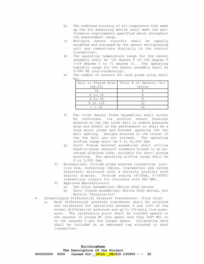
BuildingName The Description of the Project
P00000000 0000 Issued for:_(FILL _IN)BID 230905 - - 32
b) The combined accuracy of all components that make up the air measuring device shall meet the per-formance requirements specified above throughout the measurement range.
c) Multiple sensor circuits shall be equally weighted and averaged by the sensor multiplexing unit and communicate digitally to the control transmitter.
d) The operating temperature range for the sensor assembly shall be -20 degree F to 160 degree F (-29 degree C to 71 degree C). The operating humidity range for the sensor assembly shall be 0-99% RH (non-condensing).
e) The number of sensors for each probe array shall be:
Duct or Plenum Area (sq.ft)
Total # of Sensors /Lo-cation
<2 4 2 to <4 6 4 to <8 8 8 to <16 12 > = 16 16
f) Fan Inlet Sensor Probe Assemblies shall either
be contoured, low profile sensor housings mounted on the fan inlet bell to reduce pressure drop and effect on fan performance or shall be a face mount probe and bracket spanning the fan bell opening. Designs mounted in the throat of the fan bell are not allowed. The operating airflow range shall be 0 to 10,000 fpm.
g) Duct/ Plenum mounted assemblies shall utilize bead-in-glass sensors/ elements housed in an an-odized aluminum tube, suitable for duct/ plenum mounting. The operating airflow range shall be 0 to 5,000 fpm.
2) Accessories: Include probe mounted transmitter junc-tion box, connecting cables, transmitter and system electronic enclosure with a velocity profiler with digital display. Provide analog (4-20mA, 0-10VDC) transmitter outputs for interface with DDC BMS.
3) Approved Manufacturers: a) Fan Inlet Assemblies: Ebtron GOLD Series b) Duct/ Plenum Assemblies: Ebtron GOLD Series, Air
Monitor “Electra-flo” 4. Steam/Liquid Differential Pressure Transducers: (flow only)
a. Each differential pressure transducer shall be selected and calibrated for operations between 0 and 125% of the normal differential pressure and up to 150-psig line pres-sure. The calibration point shall be rounded upward to the nearest 10 inches WC (for spans less than 200" WC) or to the nearest 5 psi for larger spans. Calibration date shall be included on an embossed tag attached to each transmitter.
BuildingName The Description of the Project
P00000000 0000 Issued for:_(FILL _IN)BID 230905 - - 33
b. The accuracy, including linearity, hysteresis and repeat-ability, of the transducer for measuring differential pressure shall be better than 0.25% of the span stated above throughout a minimum of a 6:1 turndown. Turndown ratio shall be based on the actual flow span.
c. The transducer shall not be damaged by pressures of up to 500 psig on either side of the transducer and all wetted parts shall be inert in the presence of up to a 40% con-centration of ethylene or polypropylene glycol in water.
d. Provide a drain valve for each side of the pressure cham-ber. Furnish and install mounting brackets appropriate for the installation location.
e. Span and zero shall be individually adjustable. f. Shall be 2-wire and 4-20mA output. g. Approved manufacturers:
1) Tobar 2) ITT Barton 3) Dietrich - Standard 4) ABB 5) Siemens 6) Rosemont/Fischer 7) Honeywell
5. Steam/Liquid Differential Pressure Transducers: (pressure only) a. Each differential pressure transducer shall be selected
and calibrated for operations between 0 and 200% of the normal differential pressure. The calibration point shall be rounded upward to the nearest 10 inches WC (for spans less than 200" WC) or to the nearest 5 psi for larger spans. Calibration date shall be included on an embossed tag attached to each transducer.
b. The accuracy, including linearity, hysteresis and repeat-ability, of the transducer for measuring differential pressure shall be better than 2% of the span stated above throughout a minimum of a 4:1 turndown. Turndown ratio shall be based on the actual differential span.
c. The transducer shall not be damaged by pressures of up to 500 psig on either side of the transducer and all wetted parts shall be inert in the presence of up to a 40% con-centration of ethylene or polypropylene glycol in water.
d. Provide a drain valve for each side of the pressure cham-ber. Furnish and install mounting brackets appropriate for the installation location.
e. Span and zero shall be individually adjustable. f. Shall be 2-wire and 4-20 mA output. g. Approved manufacturers:
1) Tobar 2) ITT Barton 3) Dietrich - Standard 4) ABB 5) Siemens 6) Setra
6. Indication Gauges for Steam/Liquid Pressure Transducers: a. Each transducer shall come with an indicating gauge that
reads in GPM for flow measurement or inches WC for pressure sensing. The gauge shall be analog differential pressure type piped in parallel to the transducer.
BuildingName The Description of the Project
P00000000 0000 Issued for:_(FILL _IN)BID 230905 - - 34
b. The analog pressure gauge shall be selected and calibrated for the same span as the transducer it serves.
c. The accuracy, including linearity, hysteresis and repeat-ability, of the gauge for measuring differential pressure shall be better than 3% of the span stated above throughout its span. Calibration data shall be included on an em-bossed tag attached to each gauge.
d. The gauge shall not be damaged by pressures of up to 500 psig on either side of the gauge and all wetted parts shall be inert in the presence of up to 40% concentration of ethylene or polypropylene glycol in water.
e. Scale shall be a minimum of 4.5" diameter. Furnish and install two bleed fittings for each gauge and mounting brackets appropriate for the installation location.
f. Gauges shall be field mounted. Provide a LPI for readout at the DDC panel array. Provide a phenolic identification tag for each gauge and indicator.
g. Approved manufacturers: 1) Beckman 2) Moore 3) Testoterm 4) Dwyer 5) Transducer manufacturer’s gauge
7. Steam/Liquid Flow Sensors: (differential pressure type) a. Uni-directional sensors shall be of the venturi type or
velocity pressure type. They shall be constructed of stainless steel, sized to the system's range of flow, and have an accuracy of 0.5%.
b. Bi-directional sensors shall be of the velocity pressure type. They shall be constructed of stainless steel, sized to the system's range of flow, and have an accuracy of 0.5%.
c. Approved Manufacturers 1) Preso 2) Gerand 3) Dietrich-Standard (Annubar Diamond II)
8. Three Valve Manifolds for Steam/Liquid Pressure Transducers: a. Provide a three-valve manifold for each transducer. Pres-
sures of up to 500 psig shall not damage the manifold. All wetted parts shall be inert in the presence of up to a 40% concentration of ethylene or polypropylene glycol in water.
b. The manifold shall be designed for direct mounting on the transducer it serves and utilizes two quarter turn valves to provide zeroing, blocking and normal service modes.
c. Approved Manufacturers: 1) D/A Manufacturing
9. Liquid Flowmeters: (Electro-Magnetic Type)
BuildingName The Description of the Project
P00000000 0000 Issued for:_(FILL _IN)BID 230905 - - 35
a. The meter system shall consist of a primary flow sensor and transmitter. The flow sensor shall be equipped with 150-lb. flanges. The meter system shall be installed with all necessary grounding components and gaskets per manu-facturer’s instructions. The meter shall be capable of bi-directional operation. The meter shall be sized ap-propriately for the range of flow for the system. The electrodes shall be SS or Hasteloy C. The transmitter shall be provided with a remote mounting bracket, cable, integral LCD display, NEMA 4X housing, shall indicate flow rate and totalize flow, shall have an isolated 2-wire 4-20 mA linear output flow rate signal, and shall have a pulsed output signal for totalization. The transmitter shall be capable of being field calibrated and repro-grammed from the outside housing via magnetic probe or security protected integral keypad menu switching. Unit electronics shall have noise immunity. The primary flow sensor and transmitter shall be mounted in accessible lo-cations. Unit shall have the capability to maintain flow total in non-volatile memory. The flowmeter and trans-mitter as a unit shall have the following minimum charac-teristics: 1) Flowmeter Liner:
a) Heating hot water, domestic hot water, and other water systems operating at or above 110°F: Teflon
b) Chilled water, domestic cold water, and other water systems operating below 110°F: Polyure-thane
c) Steam condensate: Teflon to 300°F, Ceramic over 300°F, and as suitable for the expected fluid conditions.
2) Accuracy: a) At 1 to 33 feet per second velocity: ±0.5% of
rate. b) At 0.3 feet per second velocity: ±2% of rate.
3) Each unit shall be factory calibrated for the speci-fied flow and shall be calibrated in both directions if the application is bi-directional. Calibration shall be a minimum of three point. Specific perfor-mance test data shall be furnished with the meter.
4) Each meter shall provide two analog 4-20 mA signals or a single 4-20 mA signal and a digital contact closure on reverse flow.
5) Meters for steam condensate shall be capable of sens-ing with condensate conductivity down to 6 µS/cm.
b. Provide a phenolic tag for each transmitter to identify service and meter ID number (i.e. SECONDARY CHILLED WATER FLOW, FM-1, etc.).
c. Approved Manufacturers (Water) 1) ABB 2) Siemens 3) EMCO 4) Rosemount 5) Krohne 6) Onicon
d. Approved Manufacturers (Steam Condensate) 1) Rosemount
BuildingName The Description of the Project
P00000000 0000 Issued for:_(FILL _IN)BID 230905 - - 36
2) Krohne 3) ABB
10. Steam (Vapor) Flowmeters (Vortex-shedding type): a. The meter system shall consist of a primary flow sensor
and transmitter. The flow sensor body and wetted parts shall be SS, and shall be flanged and suitable for the service rating. The meter shall be installed with all necessary grounding components and gaskets per manufac-turer’s instructions. The transmitter shall be provided with a remote mounting bracket and cable, integral LCD display, NEMA 4X housing, shall indicate flow rate, to-talized flow, shall have an isolated 2-wire 4-20 mA linear output flow signal and a pulsed output signal for totali-zation. The transmitter shall be capable of being field calibrated and reprogrammed from the outside housing via magnetic probe or security protected integral keypad menu switching. Unit electronics shall have noise immunity. Unit shall have the capability to maintain flow total in non-volatile memory. The primary flow sensor and trans-mitter shall be mounted in accessible locations. The flowmeter and transmitter as a unit shall have the fol-lowing minimum characteristics: 1) Temperature range shall be –40-750°F. 2) Accuracy shall be 1.0% of rate and 0.1% of full scale. 3) Repeatability shall be 0.15% of flow rate. 4) Each meter shall be factory calibrated for the spec-
ified flow range prior to shipment and specific per-formance test data shall be furnished with the meter.
5) Meter range shall accommodate the minimum and maximum expected flow for the steam pressure at the installed location.
6) Meter shall be equipped with a temperature and pres-sure compensation feature.
b. Provide a phenolic tag for each transmitter to identify service and Meter ID number (i.e. MEDIUM PRESSURE STEAM FLOW – LSI BUILDING, etc.).
c. Approved Manufacturers 1) Rosemount 2) Krohne 3) ABB
11. Steam (Vapor) Flow Meters (Differential-pressure type) a. The meter system shall consist of a differential pressure
primary flow element, a differential pressure transmitter (or transmitters), and a flow monitor/computer. The flow sensor body and wetted parts shall be SS, and shall be equipped with 150-lb. flanges. The transmitter(s) and flow computer shall be provided with a remote mounting bracket and cable, integral LCD display, and NEMA 4X hous-ing. Flow computer shall indicate flow rate and totalized flow, shall have an isolated 2-wire 4-20 mA linear output signal and a pulsed output signal for totalization. Unit electronics shall have noise immunity. The transmitter shall be capable of being field calibrated and repro-grammed from the outside housing via magnetic probe or security protected integral keypad menu switching. Unit shall have the capability to maintain flow total in non-
BuildingName The Description of the Project
P00000000 0000 Issued for:_(FILL _IN)BID 230905 - - 37
volatile memory. The flowmeter and transmitter as a unit shall have the following minimum characteristics: 1) Temperature range shall be –40-750°F. 2) Accuracy shall be 1.0% of rate or better and 0.1% of
full scale. 3) Repeatability shall be 0.15% of flow rate. 4) Each meter shall be factory calibrated for the spec-
ified flow range prior to shipment and specific per-formance test data shall be furnished with the meter.
5) Meter range shall accommodate the minimum and maximum expected flow for the steam pressure at the installed location.
6) Meter shall be equipped with a temperature and pres-sure compensation feature.
7) V-cone horizontal pilot lines shall be pitched back to steam lines and shall not trap condensate.
b. Provide a phenolic tag for each meter to identify service and Meter ID number (i.e. MEDIUM PRESSURE STEAM FLOW – LSI BUILDING, FM-1 etc.).
c. Approved Manufacturers 1) McCrometer (V-cone-style meter) 2) Preso (Venturi-style meter) 3) Gerand Engineering (Venturi-style meter)
TWO METHODS OF CALCULATING ENERGY CONSUMPTION (BTUS), WITH THE RESPECTIVE EQUIPMENT REQUIRED, ARE SPECIFIED BELOW: (1) BY THE DDC SYSTEM OR (2) BY A “BTU METER”. 12.b IS USED WHEN UTILITY (REVENUE) BILLING OF A SYSTEM IS PLANNED. 12.a IS USED WHEN ENERGY CONSUMPTION IS COLLECTED FOR INFORMATIONAL PURPOSES ONLY. ASSURE THE CONTROL DRAWINGS INDICATE WHICH METHOD, IF ANY, IS TO BE USED FOR EACH SYSTEM.
12. BTU Metering a. DDC BTU metering shall be accomplished using the following
equipment at each metering point: 1) One (1) liquid flowmeter unit with transmitter as
specified elsewhere in this section. 2) Two (2) high-precision matched temperature sensor as-
semblies with transmitters as specified elsewhere in this section. Sensor with SS well shall be installed in each respective supply and return pipe as shown on project drawings.
3) These devices shall be wired to a local DDC panel. Calculations for instantaneous and totalized load shall be incorporated into the panel control code, and the necessary virtual points shall be created to allow remote monitoring and trending via the DDC sys-tem.
b. When a BTU meter is indicated on the control drawings, provide a flow/BTU computer which is programmable for var-ious flow meter types including linear, square law, or multi-point linearization data interpretation. 1) Inputs shall include:4-20ma flow from flow meter and
4-20ma from two temperature sensors. 2) Flow and temperature inputs shall be simultaneously
connected to this computer and looped to the local DDC panel.
BuildingName The Description of the Project
P00000000 0000 Issued for:_(FILL _IN)BID 230905 - - 38
3) Flow/ BTU computer shall operate in an environment of 0 to 50 C, shall include a keypad for data input and retrieval, and an EEPROM/nonvolatile RAM. Unit shall calculate and provide: a) Two 4-20ma analog outputs indicating btu, mass
or volume flow rate, temperature 1, temperature 2, delta temperature, pressure, density, and peak demand.
b) One isolated pulse output indicating btu, mass or volume total
c) Two NC/NO relay outputs assignable to trip ac-cording to various rate, total, temperature or pressure readings, programmable as latching or non-latching, or as pulsed output of a total.
4) Outputs shall be stored in a battery backed data log-ger, selectable for continuous or periodic log modes.
5) Unit shall have a real time clock and shall date stamp logged data. Unit shall have an RS-232 port and shall be capable of setup from a laptop computer. The supplier shall set up and verify BTU measurement and shall train U of M personnel in all aspects of BTU computer setup and operation.
6) Computer shall calculate and display heat, mass or Volume flow rate, resettable total, non-resettable total, temperature input 1, temperature input 2, delta temperature, density, pressure, peak demand, and time/date stamp.
7) Provide a phenolic tag for each transmitter and flow computer (as applicable) to identify service and ID number (i.e. CHILLED WATER BTU METER – LSI BUILDING, etc.).
8) Mount Flow/BTU computer in a NEMA 4 enclosure: Minimum size 16” (H) x 14” (W) x 8” (D), hinged cover, pad-lockable latch, and stainless steel hinge. Provide cutout in enclosure face and mount computer in face. Where multiple computers are supplied, they may be mounted in a common enclosure.
9) Approved Manufacturers and Models for Flow/BTU Com-puter: a) Kessler-Ellis Supertrol II with MS816 enclosure.
D. Electronic to Pneumatic Transducers
1. Provide transducers to convert electronic signals from the DDC analog output modules to linear proportional pneumatic signals for all DDC controlled modulating pneumatic devices. The trans-ducer shall be a panel-mounted device, with hand/auto switch, override dial for manual override control, and a 0-30 psig output gauge. Supply voltage shall be 19-26 VAC. Control signal shall be 0-10 VDC or 4-20 mA. Output accuracy shall be 1/4 psig at 75 Deg. F, producing a 0-15 psig pneumatic signal. Output repeatability shall be .05 psig maximum. Transducers shall be high capacity non-bleed devices with a minimum output capacity of 500 SCIM, except special circumstances that require a constant bleed controller with branch exhaust on signal loss.
2. Approved Manufacturers: a. Non-bleed Type:
1) Siemens
BuildingName The Description of the Project
P00000000 0000 Issued for:_(FILL _IN)BID 230905 - - 39
2) ACI – EPC 3) Kele 4) Mamac
b. Bleed Type: 1) ACI – EPC
E. Pressure to Electronic Transducers
1. Provide transducers to convert linear proportional pressure signals to DDC analog input modules. The transducer shall be a panel-mounted device, with input pressure snubber, as re-quired, and gauge. Supply voltage shall be 19-26 VAC. Control signal shall be 4-20 mA. Accuracy shall be 1 percent full scale. Thermal effect shall be less than 1 percent full scale on zero and less than 1 percent of reading on span. Transducer shall have elastomer seals and SS wetted parts.
2. Approved Manufacturers: a. Siemens b. Setra c. Modus d. ACI e. Dwyer
F. Carbon Dioxide Sensors:
1. Carbon dioxide sensing cell shall consist of a nondispersive infrared carbon dioxide gas cell that uses a pulsed source and has no free air optical path. Output shall be linearized 4-20 mA for use with 24 VDC input. The unit shall be specifically designed for the wall or duct application specified. Duct aspiration boxes shall be by the manufacturer. Unit shall have span adjustment. The unit shall have no moving parts.
2. Minimum requirements: a. Range: 0-2,000 ppm b. Accuracy: 3 % of full scale c. Repeatability: 1% of full scale d. Power Consumption: less than 3 watts e. Zero Drift at Constant Temp.: 100 ppm per 24 hrs(random
not cumulative) f. Max. allowable Drift in 1 year: 20 ppm
3. Unit shall not require calibration for a period of 1 year or more.
4. Approved Manufacturers: a. Valtronics b. GE/ Telaire
G. Carbon Monoxide and Combustible Gas Sensors:
1. Sensors shall be a micro-processor-based system for continuous monitoring and use catalytic, electro-chemical, diffusion cell, or solid-state type sensing. Output shall be linearized 4-20 mA for use with 24 VDC input with green LED normal operation indicator. Unit shall provide a SPDT pilot duty low voltage alarm contact with an adjustable set point. The unit mounting shall be wall, duct aspiration, or ceiling to suit application. The unit shall specifically designed for the application and shall be explosion proof, as required. Unit shall have single point set point and span adjustment. The unit shall have no moving parts. Units mounted outdoors shall be waterproof and rustproof.
BuildingName The Description of the Project
P00000000 0000 Issued for:_(FILL _IN)BID 230905 - - 40
2. Minimum requirements: a. Range: as required for application; ppm, %, %L.E.L. b. Accuracy: 3-5% of full scale c. Repeatability: 1% of full scale d. Power Consumption: 5 watts or less e. Relay contact rating: 5 amp at 24 VDC, 150 VA max. induc-
tive f. Zero Drift at Constant Temp.: 0 per 24 hrs (random not
cumulative) g. Max. allowable Drift in 1 year: 1% of full scale.
3. Approved Manufacturers: a. Draegar b. Honeywell Analytics (Vulcain)
H. Current Sensing Relays
1. Provide current sensors with donut transformers capable of mon-itoring AC current, maximum input current ranges from 20 to 300 amp, peak, with digital output signals having adjustable high and low current trips. An LED shall provide visual indication and shall not bleed through. a. Provide special current sensing relays designed to monitor
belt breakage, when indicated or described in the Sequence of Operation.
2. Approved Manufacturer: a. Neilsen Kuljian b. Veris Industries c. ACI (Automation Components Inc)
I. Liquid Detectors
1. Liquid detectors shall utilize microchip technology for detec-tion of conductive liquids through one of the following types of sensors: gold-plated probes, self-adhesive sensor tape with copper electrodes and durable cotton cover, or rope type sen-sor. Detectors shall be selected based on the best use for the application. Power requirement shall be 11-27 VAC or VDC and have a green LED normal operation indicator. Unit shall have a SPDT pilot duty low voltage alarm contact. Unit shall be waterproof and rustproof. A red LED shall indicate the presence of liquid. Unit shall have an adjustable set point.
2. Approved Manufacturers- Spot Detectors: a. DiversiTech “Wet Switch” b. Water Alert
3. Approved Manufacturers- Rope or Ribbon Detectors a. RLE Technologies b. Water Alert c. Kele
J. Condensation Sensor - Pipe Mounting Type
1. Sensor with built-in relay contact that opens upon detection of condensation, for sensing condensation when mounted on bare pipe. a. Supply voltage: 24 VAC/VDC ±10% b. Power consumption: Maximum 1.6 VA c. Relays contacts: rated 1 amp @ 24 VAC/VDC d. Operating temperature: -20… +50°C e. Display: LED, green – power supply ok, red – condensation
sensed, contact open.
BuildingName The Description of the Project
P00000000 0000 Issued for:_(FILL _IN)BID 230905 - - 41
f. With pipe mounting bracket.
K. Occupancy Counters (People Counters)
1. Dual Sensor - Differential Thermal Imaging Counter a. General
1) Provide combination BACnet-MS/TP and Analog Output counting devices for Dynamic Ventilation Reset Con-trols to be mounting where indicated on the plans and controlling ventilation to occupied zones as popula-tions vary, in compliance with the Ventilation Rate Procedure in ASHRAE 62.1-2013 and 2016.
b. Counters shall provide data on net zone popula-tions to dynamically calculate the ASHRAE Stand-ard 62.1 Ventilation Rate. 1) Each counter shall consist of a center-top door frame
mounted counter, using a dual thermopile differential thermal imaging counters, an integral microprocessor-based design capable of providing net population data to the controls network for use in ventilation reset based on accurately measured real- time zone popula-tions.
2) Counter with steel enclosure shall have an overall size of: 6.12L x 2.94W x 1.36H inches and weigh ap-prox. 0.25 lbs.
3) Counters shall have an environmental operating range of no less than 65° F to 85° F and 5% – 95% RH, non- condensing.
c. Population Counter Design and Counting Performance 1) Counter shall be mounted to provide zone entry and
exit data to the network for maintenance of a net zone population value to less than ±5% of actual or ±3 people, whichever is larger.
2) Counter design shall be optimized for single en-try/exit interior doors, ≤ 42 x ≤ 96 in.
3) Small deviations or accumulation in counts shall be adjusted when “population reset interval” is selected during configuration and set up. Upon activation, the total net population in memory shall be ‘zeroed’ based on the user-determined reset period selected or every 24 hours during a predetermined non-occupied period.
4) Power, Connectivity and Communications a) The BACnet / analog combination counters shall
be capable of communicating with other devices using an RS-485 standard interface and BACnet-MS/TP protocol, implemented as a Master node.
b) Communication speed shall be field-selectable by dip switch between 9.6, 19.2, 38.4 and 76.9 kBaud.
c) The counter-network communications shall be ca-pable of field configuration and setup using a simple dip- switch interface.
d) A simultaneous 0-10 VDC scalable and protected analog output shall also be available to provide net counts.
e) All counters shall be powered with individual 24 VAC transformers (22.8V to 26.4V under load) @1.2 V-A nominal.
BuildingName The Description of the Project
P00000000 0000 Issued for:_(FILL _IN)BID 230905 - - 42
2. The manufacturer’s authorized representative shall review and approve counter position placement for each location indicated on the plans.
3. Accepted Manufacturer: EBTRON, Inc. Model CENSUS - C100, Sin-gle-entry interior door occupancy counter.
L. Alarm Indication Station
1. Alarm indicating station with red alarm LED, alarm horn, horn momentary silence switch, adjustable alarm delay and alarm re-peat time, and alarm status relay. a. Supply Voltage: 24 VAC @ 100 mA or 24 VDC @ 34 mA. b. Alarm Time Delay: None, or 1 to 31 seconds in one-second
increments, or 10 to 310 seconds in 10-second increments. c. Alarm Horn: Continuous or pulsed tone, 70 db minimum. d. Alarm Repeat Time: None, or 1 to 7 minutes in one-minute
increments, or 10 to 70 minutes in 10-minute increments. e. Alarm Relay: SPDT, 0.5A @ 24 VAC, 1.0A @ 30 VDC, follows
horn or lamp action, selectable. f. Connections: Screw terminals, 22 – 14 AWG wires. g. Mounting: Brushed stainless steel plate mountable to stand-
ard single junction box, with two screws provided. 2. Accepted Manufacturer: Kele Model RAD-1.
2.7 ELECTRIC COMPONENTS
A. Components shall be Honeywell, Johnson, or Siemens, unless listed otherwise.
B. Low temperature detection thermostats shall be duct type, fixed 5 deg. F differential, range 30 to 60 deg. F. Sensing element shall have a 20-foot long capillary tube responding to the lowest temper-ature sensed along any 12 inches of bulb length. Switch shall be SPDT 120 VAC, UL listed, rated for 10 amps at 120 VAC full load. Unit shall be manually reset. Provide one thermostat for every 20 square feet of coil surface.
C. High temperature detection thermostats shall be two-position type, range and element shall be suitable for the service, single or double pole, normally open or normally closed as required. Set point shall be adjustable over the full range. Switch shall be UL listed, rated for 10 amps at 120 VAC full load. Unit shall be manually reset.
D. Immersion electric thermostats shall be two-position type, range and element shall be suitable for the service, single or double pole, normally open or normally closed as required, with stainless steel separable well. Set point shall be adjustable over the full range. Switch shall be UL listed, rated for 10 amps at 120 VAC full load.
E. Remote-bulb electric thermostats shall be two-position type, range and element shall be suitable for the service, single or double pole, normally open or normally closed as required, with stainless steel separable well as required. Set point shall be adjustable over the full range. Switch shall be UL listed, rated for 10 amps at 120 VAC full load.
BuildingName The Description of the Project
P00000000 0000 Issued for:_(FILL _IN)BID 230905 - - 43
F. Wall-mounted electric thermostats shall be two-position type, range and element shall be suitable for the service, single or double pole, normally open or normally closed as required. Set point shall be adjustable over the full range. Switch shall be UL listed, rated for 10 amps at 120 VAC full load.
G. Strap-on electric thermostats shall be two-position type, range and element shall be suitable for the service, single or double pole, normally open or normally closed as required. Set point shall be adjustable over the full range. Switch shall be UL listed, rated for 10 amps at 120 VAC full load.
H. Differential Pressure Switches:
1. Shall provide electrical switching action upon a sensed pres-sure differential increase between two points. Sensitivity shall be suitable for the application. Set point shall be adjustable over the full range of the device. Switching action shall SPDT. Electrical switch rating shall be 10 amps at 120 VAC, minimum.
2. Pressure rating of switch and connecting tubing: a. Fan - Rated for 12 inches WC. b. Pump – Maximum deadhead system pressure.
3. Switches used for safety shutdown applications shall be of the manual reset type.
4. Approved Manufacturers: a. Honeywell b. Siemens c. Dwyer d. Cleveland Airflow
I. Limit Switches:
1. Limit switches shall be oil tight type with appropriate opera-tor to provide required function.
2. Approved Manufacturers: a. Honeywell b. Siemens c. Allen-Bradley d. GE e. Square D
J. Control Relays and Contactors:
1. Relays shall be a minimum DPDT, of proper coil voltage, with neon indicator light, and of sufficient rating for specified purpose. Relay base shall be of the screwed terminal type.
2. Contactors shall be definite purpose type, have adequate number of poles, of proper coil voltage, and of sufficient rating for specified purpose. Contactors used for DDC interface control shall contain a Hand-Off-Auto switch.
3. Approved Manufacturers: a. Dayton b. Siemens c. Allen-Bradley d. GE e. Square D f. Functional Devices- RIB g. IDEC h. Omron
BuildingName The Description of the Project
P00000000 0000 Issued for:_(FILL _IN)BID 230905 - - 44
K. Selector Switches:
1. Switches shall be multiple position type, oil-tight, water-tight, dust-tight, have the adequate number of contact blocks, capable of additional contact blocks, and of sufficient rating for specified purpose. Nomenclature plate shall be provided with appropriate wording, units, etc.
2. Approved Manufacturers: a. Dayton b. Siemens c. Allen-Bradley d. GE e. Square D
L. Push Buttons and Pilot Lights:
1. Push button switches and pilot lights shall be, oil-tight, watertight, dust-tight, have the adequate number of contact blocks, capable of additional contact blocks, and of sufficient rating for specified purpose. Nomenclature plate shall be provided with appropriate wording, units, etc.
2. Pilot lights shall be neon or LED, push-to-test type with re-placeable lens. Lens shall be of the appropriate color for application served.
3. Approved Manufacturers: a. Dayton b. Siemens c. Allen-Bradley d. GE e. Square D
M. Fuse Holder/Disconnects:
1. Fuse holder/disconnects shall be provided for all control cir-cuits inside auxiliary control panels, and shall be of appro-priate size/type for service.
2. Approved Manufacturers: a. Little Fuse b. Dayton c. Buss d. GE
N. Terminal Blocks:
1. Terminal blocks shall be modular, barrier type, direct mount, single pole, and snap together to any required number of poles. Units shall be rated for 300 volts, 20 amp., handle wire sizes from 22-12 AWG, and have a marking strip for identification.
2. Approved Manufacturers: a. Cooper-Bussman b. Weidmuller c. Kele d. Buss e. GE
O. Toggle Switches:
BuildingName The Description of the Project
P00000000 0000 Issued for:_(FILL _IN)BID 230905 - - 45
1. A toggle switch shall be provided for every auxiliary and local control panel that utilizes a 120 VAC power source as a means to turn off the power to that panel and shall be of appropriate size/type for service. Toggle switches shall be rated 120/277 volts, 20 amps, SPDT, specification grade, extra-heavy duty, back and side wired, with brown handles.
2. Approved Manufacturers: a. Leviton b. Pass & Seymor c. Hubbell d. Arrow Hart e. Bryant
2.8 ELECTRICAL ACCESSORIES
A. Wiring and Conduit
1. The MSCC shall provide all DDC and related control wiring, conduit, and J-hook cable hanging system. Wire and cable shall be pulled from device or control point to the DDC, Auxiliary, UPS, or LPI panels and run between DDC, Auxiliary, UPS, or LPI panels, with 6'-0" spare coiled at the panel. All wire and cable shall be labeled and tagged 4 inches down from the point at which the wire enters the cabinet with the corresponding point number.
2. All wiring carrying voltages greater than 24 volts shall be run in conduit.
3. All wiring carrying voltages 24 volts nominal or less shall be run as follows: a. Wiring routed in shafts, walls, below grade, and in any
concealed or inaccessible space, or above ceilings requir-ing the use of a tool to access or held in place by clips or similar devices: run wiring in conduit.
b. Wiring routed in exposed locations such as mechanical and electrical rooms or in rooms without ceilings (i.e. ex-posed to deck above): run in conduit.
c. Network wiring: run in conduit to nearest cable tray. d. DDC wiring above accessible lay-in ceiling areas: Utilize
J-hook hangers and/ or utilize facility cable tray. 1) Provide UL Listed zinc electro-plated steel or plas-
tic J-hooks, sky blue color, plenum use approved, with minimum 1-inch wide cable support area, rated for the cable type being supported. Provide with integral ca-ble retainer strap to provide containment of cables within the hanger.
2) Install J-hooks with J-hook bottoms a minimum of 10 feet A.F.F. and no less than 2 feet above the ceiling.
3) Space hangers at maximum 5 foot intervals, with ad-ditional hangers located a maximum of 3 feet from both sides of any change in direction. Wiring shall not sag more than 12 inches between J-hooks. Install wiring and J-hooks in a neat and workman-like manner, routed parallel or perpendicular to the building col-umn lines.
BuildingName The Description of the Project
P00000000 0000 Issued for:_(FILL _IN)BID 230905 - - 46
4) Install to protect wire from damage and to allow for wire replacement. Do not exceed 50 % of the wire capacity specified by the J-hook manufacturer (first installation), or route control wiring in non-con-trol-wiring J-hooks.
e. Wiring to wall mounted devices such as room sensors, switches, and similar devices: 1) NEW CONSTRUCTION: Route wiring in wall in minimum 1/2
inch conduit. Stub conduit up/down into accessible ceiling space, terminating conduit with a 90 degree bend and a strain relief to prevent wire damage. In-stall wall box for device mounting.
2) RETROFIT (EXISTING WALL CONSTRUCTION): Route wiring in wall, no conduit is required. Install wall box for device mounting.
f. Wiring to perimeter radiation valves and similar control devices requiring wiring to be routed in walls: Route wiring in wall in minimum 1/2 inch conduit. Stub conduit up/down into accessible ceiling space, terminating conduit with a 90 degree bend and a strain relief to prevent wire damage. Provide maximum 12 inch long flexible metal con-duit for the final connection to the device.
4. Conduits shall be sized on a maximum fill of 40% capacity. 5. Four separate conduit systems shall be provided:
a. DO/DI and 120 VAC control wiring. b. AO/AI wiring. c. Pneumatic tubing. d. Network cables. Exception: DO’s, DI’s, AI’s, and AO’s (including pneumatic tub-ing) installed between VSD’s and DDC panels may share the same conduit.
6. All junction boxes and couplings on conduit containing DDC related wiring or pneumatic tubing shall be painted sky blue color. Alternative: Allied Tube True Color® EMT, color blue, may be used in lieu of painted fittings and junction boxes.
7. All exposed DDC wiring shall utilize a sky blue insulation outer jacket color.
8. Data transmission cabling and equipment grounding procedures shall meet the latest FCC guidelines for electromagnetic field generation.
9. All control wiring sizes and types shall meet the equipment manufacturer's recommendations.
10. All control wiring shall have insulation rated for 300 volts minimum, and be installed per NEC requirements. Exposed wiring running in return plenums, air handling devices, and where required by code shall be plenum rated.
11. Wiring requirements for controllers on air terminal units: a. Provide all necessary 24 VAC transformers, 24 VAC power
distribution wiring, etc. to controllers for a complete operating system. Transformers shall have primary and secondary fuse protection and shall be mounted in an elec-trical closet, auxiliary panel or other suitable accessi-ble location with disconnecting means. Provide a pilot light for each transformer, to indicate the presence of load power.
BuildingName The Description of the Project
P00000000 0000 Issued for:_(FILL _IN)BID 230905 - - 47
b. Terminal fittings or insulating bushings shall be used to protect wiring associated with controllers at enclosures, junction boxes, etc.
B. Provide all necessary 24 VAC transformers, 24 VAC power distribution wiring, etc. for a complete operating system. Transformers shall have primary and secondary fuse protection and shall be mounted in an electrical closet, auxiliary panel or other suitable accessible location with disconnecting means. Provide a pilot light for each transformer, to indicate the presence of load power.
C. Provide conduit and wiring to power all 120 VAC control accessories such as flow meters, BTU meters, data acquisition panels and actu-ators. Feed this power from an auxiliary control panel, with a separate disconnect and fuse for each device, located in the auxil-iary panel.
D. For air terminal controllers, provide 120 VAC conduit and wiring between electrical panels and controller power supply transformers. Power for terminal controllers shall be from a dedicated 20A power circuit, as shown on construction documents (CD’s). In general, only one circuit shall be allowed per electrical closet, unless otherwise directed by project engineer.
1. For renovation work, MSCC shall utilize existing dedicated cir-cuit when available and either utilize existing transformer if adequate or provide new transformer(s). When an existing ded-icated circuit is not available, provide new per above and as shown on construction documents. When not shown on CD’s, re-quest proper circuiting by project engineer.
SPECIFICATION EDITOR: THE AE SHALL CLEARLY INDICATE SOURCE OF POWER FOR ALL DDC CONTROLS. POWER SOURCE (NORMAL VS EMERGENCY) & PRIORITY SHALL MEET OR EXCEED THAT OF THE EQUIPMENT BEING CONTROLLED.
E. Power source (i.e. normal vs. emergency power & emergency power priority) to all controllers and associated controlled devices shall match that of the equipment and/ or system being controlled.
2.9 AUTOMATIC CONTROL VALVES AND ACTUATORS
A. General:
1. With the exception of air terminal controllers, actuators shall be pneumatic unless specifically noted otherwise on the draw-ings.
2. Valve bodies 2 inches IPS and smaller shall be single seated bronze and shall have screwed end connections. Valve bodies 2-1/2 inches IPS and larger shall be cast iron and shall have flanged end connections. Valve stem packing shall be tetra-fluorethylene, spring-loaded, self-adjusting. Packless con-struction is acceptable. Valve linkage shall have an adjust-ment for valve lift. Valve to have rising stem, renewable seat and disc, repackable under pressure.
3. Valve rangeability shall be no less than 50:1 for valve Cv ≤ 1, no less than 100:1 for valve Cv > 1.
4. When indicated, provide separate SPDT limit switches which ac-tuate at the full open and full closed valve position.
BuildingName The Description of the Project
P00000000 0000 Issued for:_(FILL _IN)BID 230905 - - 48
B. High performance butterfly valves may be used when approved for valves 2-1/2" and larger and shall be full lug, have carbon steel body, 316 stainless steel offset disc, one-piece stainless steel shaft and bearings with thrust surfaces, PTFE seat, Teflon stem packing and rated for 150 psi and 450 degrees F, and in compliance with Related Section “Valves”.
STEAM CONTROL VALVES: REVISE THE VALVE PRESSURE DROP SPECIFIED BELOW TO THAT APPROPRIATE FOR YOUR PROJECT. FOR EXAMPLE, FOR LOCATIONS CLOSE TO THE CENTRAL POWER PLANT, A PRESSURE DROP HIGHER THAN THE INDICATED 4 PSIG WOULD BE APPROPRIATE. ALSO NOTE THAT THE BELOW VALVE SIZING CRITERIA ASSUMES THAT THE STEAM PRESSURE REQUIREMENT FOR THE EQUIPMENT SERVED BY THE CONTROL VALVE IS 1 PSI OR LESS. ALWAYS VERIFY THE EQUIPMENT PRESSURE REQUIREMENT AND MODIFY THE BELOW ACCORDINGLY.
C. Steam valve bodies and trim shall be rated for scheduled saturated steam service pressures. Steam valve replaceable plugs and seats shall be stainless steel, hardened to not less than 500 Brinnel. Valves shall have modified linear characteristics and shall be sized based on a 5 psig inlet pressure and a maximum drop of 4 psig.
ALTHOUGH AVAILABLE UP TO 4", BALL VALVES SHOULD TYPICALLY ONLY BE USED FOR SMALL CONTROL VALVE APPLICATIONS, E.G. FAN COILS. THIS SPECIFICATION IS ONLY FOR BALL VALVES UP TO 3/4" DIAMETER. DESIGNER SHALL SPECIFICALLY NOTE ON THE DESIGN DRAWINGS WHERE BALL STYLE CONTROL VALVES WITH ELECTRIC ACTUATORS ARE TO BE USED. BE AWARE OF THE MAXIMUM DIFFERENTIAL PRESSURE RATING (D.1.H) FOR THESE TYPE VALVES. NOTE THAT THE MINIMUM FLUID TEMP. RATING IS 35˚F; THIS BALL VALVE SPEC IS NOT SUITABLE FOR LOW TEMP SERVICE, HOWEVER LOW TEMP TRIM IS AVAILABLE, CONSULT MFR.S.
D. Ball Style Control Valve and Actuator Assembly (provide where spe-cifically noted on the design drawings):
1. Control Valve Body: Quarter turn ball valves, 2-way and 3-way configuration as indicated, for 2 position or modulating ser-vice, with the following features: a. 1/2” or 3/4” valve size. b. Forged brass body with female NPT end connections. c. Nickel or chrome plated brass ball, with Teflon reinforced
EPDM O-ring seals. d. Blow-out proof brass stem with double O-ring EPDM seals. e. Shall provide safe and reliable operation in water or in
up to 50% glycol/water solutions, at fluid temperatures between 35°F and 212°F and static pressures up to 300 psi.
f. Ball and stem seals shall be formulated to prevent degra-dation by typical water treatment chemicals and Chlora-mines.
g. Minimum close-off rating: 200 PSI. h. Differential pressure rating (valve operating): 30 PSID
maximum. i. Downstream leakage: maximum of 0.01% of design flow at
rated close-off differential pressure. j. 0 – 90 degree angle of rotation. k. Valves for modulating service shall be equipped with a
characterized ball (glass filled polymer flow insert) that provides an equal percentage flow characteristic.
BuildingName The Description of the Project
P00000000 0000 Issued for:_(FILL _IN)BID 230905 - - 49
l. Valves for two position control shall be reduced port type as required for the appropriate valve Cv.
m. Provide valves with the flow coefficient indicated, or if not indicated, subject to engineer's approval, with a Cv appropriate for good control and considering the system differential pressure available.
2. Actuators: UL listed electronic rotary actuator designed for operation with the ball type control valve, with the following features: a. The actuator shall be of the same manufacturer as the valve
body and shall be integrally mounted to the valve at the factory.
b. For direct coupling to the valve shaft without the use of linkages, to an ISO-style mounting pad.
c. Minimum cycle life: 60,000 full strokes at maximum rated torque.
d. Torque: as required for smooth positioning and closure of the valve against a maximum differential pressure of 30 PSI and to provide close-off up to 200 PSI.
e. Motor runtime to rotate the valve ball 90°: 90 seconds maximum, 20 seconds minimum.
f. Spring return runtime to rotate the valve ball 90°: 90 seconds maximum, 20 seconds minimum.
g. For use with a 24VAC power supply with the ability to operate off the same power supply required for the tem-perature controller.
BELOW PARAGRAPH ASSUMES MODULATING CONTROL. IF FLOATING POINT VALVE ACTUATION IS DESIRED, MODIFY THE BELOW ACCORDINGLY. h. For use with 0-10Vdc output proportional plus integral
room controllers, fully compatible with the specified tem-perature controller. Unless indicated otherwise on the control drawings: 1) Heating coil (non-vivarium applications): Normally
open spring return actuation. 2) Heating Coil (vivarium applications): Normally closed
spring return actuation. 3) Cooling coil: Normally closed spring return actua-
tion. i. Electronic stall detection/overload protection. Actuator
shall sense that maximum rotational position has been reached even when control signal is still applied and stop rotating prior to actuator damage.
j. Rotation mechanically limited by adjustable integral limit stops.
k. Mechanical range adjustment. l. Valve position indicator. m. Actuator/actuator housing: Brushless DC motor design, NEMA
type 1 or 2 enclosure, die-cast aluminum alloy or UL 94 listed plastic housing, lubricated gears, with a thermal barrier to prevent condensation on the actuator parts when used for chilled water applications. It shall be possible to rotate the actuator to any of four rotational angles in 90° increments, relative to the valve body.
n. Ambient temperature operating range: -20°F and 120°F. o. Maximum actuator noise level, running or spring return: 40
dBA.
BuildingName The Description of the Project
P00000000 0000 Issued for:_(FILL _IN)BID 230905 - - 50
3. 2 year unconditional warranty, parts and labor. 5 year uncon-ditional parts warranty.
E. Hydronic system valve bodies and trim shall be rated for service pressures through 125 psig at 250 deg. F, globe style. Hydronic system valves shall have replaceable plugs and seats of SAE 72 brass or AISI 300 series stainless steel, selected for maximum lift under application conditions. Maximum pressure drop across any hydronic system valve at maximum flow and valve size shall be as indicated. Two-way valves shall have equal percentage characteristics for heat-ing and cooling applications, either linear or equal percentage for other applications as appropriate, linear for three-way valves. When not indicated, valves shall be sized for a pressure drop of 3 psig for chilled water and 4 psig for hot water.
F. Standard Valve Actuators:
1. Pneumatic, rolling diaphragm, spring loaded, piston type. 2. Spring range shall be as required for non-overlapping sequenc-
ing or as indicated on drawings. 3. Ratio relays or cumulators used for sequencing valves are not
acceptable unless specifically indicated on the drawings. 4. Valves shall spring return to normal position as indicated. 5. Select with sufficient close-off power for system pressure,
pump shut off head, highest operating torque, and torque re-quirements of valves that may stick because of infrequent use.
6. Select to provide smooth proportioning control under operating conditions normal to the system.
G. Butterfly Valve Actuators:
1. Pneumatic actuators shall be rotary type with rack and pinion to provide constant output torque rated for at least 125 per-cent, pilot positioner with gauges, spring return, adjustable travel stops, factory tested, factory lubricated, self-draining body, integral pneumatic parting, localized mechanical position indicator readable at 25 feet, 0-90 deg. reversible operation, capable of operating in any valve mounting attitude, capable of being mounted in line or transverse to pipeline, and bolt directly to valve top plate. Valves shall be actuated with 60-psig air and 3-15 psig pilot service. Valves used for isolation do not require pilot positioners. Actuator shall include a manually operated hand wheel for manual override.
SPECIFICATION EDITOR: WHEN THE USE OF ELECTRIC ACTUATORS IS PLANNED THE METHOD OF GETTING POWER TO THOSE ACTUATORS MUST BE CONSIDERED. READ THE BELOW SPEC SECTION CAREFULLY AND NOTE THE SIZE RANGE FOR VARIOUS ACTUATOR VOLTAGES. THE CONTROLS CONTRACTOR SHALL NOT RUN POWER WIRING ABOVE 120V. THEREFORE:
FOR 120V ACTUATORS, POWER TO SUCH ACTUATORS IS THE RESPONSIBILITY OF THE CONTROLS CONTRACTOR AND IS TO BE ROUTED FROM THE DDC AUXILIARY PANEL (SEE SECTION 2.8). IF YOUR PROJECT HAS A LARGE NUMBER OF 120V ACTUATORS THE STANDARD (2) 20 AMP CIRCUITS RUN TO THE DDC AUX. PANEL MAY NOT BE ENOUGH. DETERMINE THE TOTAL AMPERAGE OF SUCH ACTUATORS AND DIRECT THE ELECTRICAL DESIGNER TO DESIGNATE ADDITIONAL 120V CIRCUITS TO THE DDC AUX. PANEL, IF REQUIRED.
BuildingName The Description of the Project
P00000000 0000 Issued for:_(FILL _IN)BID 230905 - - 51
FOR 208V OR 480V ACTUATORS, POWER TO THE ACTUATORS SHALL BE DESIGNATED AS THE RESPONSIBILITY OF THE ELECTRICAL CONTRACTOR. FOR THESE HIGH VOLTAGE ACTUATORS, DIRECT THE ELECTRICAL DESIGNER TO INDICATE POWER TO EACH ACTUATOR ON THE ELECTRICAL DRAWINGS. THIS POWER SHALL NOT BE RUN OUT OF OR THROUGH THE DDC AUXILIARY PANEL. 2. Electric actuators shall have permanent split capacitor, re-
versible electric motor which drives a compound epicyclic gear, thermal overload protection, factory tested, factory lubri-cated, localized mechanical position indicator readable at 25 feet, 0-90 degree reversible operation, bolt directly to valve top plate. Housing shall be weatherproof and suitable for outdoor location. Provide thermostatically controlled heater for prevention of condensation at low temperatures. Actuator voltage shall be 120 VAC through 12” and 208 or 480 VAC above 12”. 120V actuators shall be fed out of the auxiliary panel with a separate disconnect and fuse. Disconnect and fuse to be located in the auxiliary panel. 208V or 480V actuator power shall be provided to 208/480V actuators by others. In all cases the MSCC shall provide the required control wiring to the actuators. Actuator ambient temperature range shall be -20 deg. F to +140 deg. F. Actuator shall include a manually operated hand wheel for manual override of the valve position.
H. Electronic valve actuators used with air terminal controllers shall be 24 VAC and use 3-position floating control, 7/32” (5.5 mm) stroke minimum, shall be direct-coupled to valve bodies without the use of tools, shall have sufficient power to prevent valves from lifting off their seats, shall provide visual position indication, shall include manual override knob, and shall be UL-listed for plenum installations. Actuators shall be fail-safe or fail-in place as follows:
1. Actuators shall be fail-safe open for perimeter heating appli-cations.
2. Actuators shall be fail-in-place for reheat control valves and cooling coil valves.
I. Typical valve body/actuator control actions shall be as follows:
1. Heating coil valves (non-vivarium) shall be normally open to flow through the coil.
2. Heating coil valves (vivarium) shall be normally closed to flow through the coil.
3. Heat exchanger valves (steam or water) shall be normally open to flow through the heat exchanger.
4. Cooling coil valves shall be normally closed to flow through the coil.
5. Humidifier valves shall be normally closed to flow through the humidifier.
6. Condenser water valves shall be normally open to flow through the cooling tower.
7. Isolation valves shall be normally open. 8. Drain valves shall be normally closed.
J. Approved Manufacturers:
1. All control valves except butterfly type: a. Siemens b. Honeywell c. Johnson Controls
BuildingName The Description of the Project
P00000000 0000 Issued for:_(FILL _IN)BID 230905 - - 52
d. Belimo (Ball Style Control Valve & Actuator only) 2. High performance butterfly valves:
a. Jamesbury - 815L b. Watts - QF series X c. Dezurik – BHP d. Grinnell – WINN e. Xomox Pliaseal f. Bray – Braylok Series 41
CONTROL DAMPERS SHALL BE SCHEDULED ON THE DRAWINGS. INDICATE THE DAMPER STATIC PRESSURE AND VELOCITY RATING IN THE SCHEDULE.
2.10 AUTOMATIC CONTROL DAMPERS
A. Multi-blade type. Provide with parallel blades for two-position, throttling, and modulating service unless noted otherwise. Provide required drive axles, linkage, jackshafts, and accessories for proper damper operation. Damper blades, frames, linkages, jack-shafts and other parts of the damper actuation system shall not distort or rack during operation. Dampers shall close tightly, and operate in a smooth, hesitation and slack-free manner over the entire range of travel, at the maximum air pressure and velocity at the mounting location. Additionally, multiple section dampers shall op-erate in unison section-to-section.
B. Face and bypass dampers shall each be capable of passing 100% of unit rated CFM. Pressure drops shall be approximately the same in either extreme position, including the pressure drops of coils and bypass components.
C. All automatic control dampers shall conform to these specifications, including those provided by equipment manufacturers.
D. All control dampers shall be low leakage type and shall meet the following minimum requirements:
1. Leakage: 6.0 CFM/sq. ft. max. at 3" WC. 2. Frames: 13 gauge (minimum) galvanized steel, minimum 2 inches
in frame depth, welded or riveted with corner reinforcement. 3. Blades: 16 gauge (minimum) galvanized steel or aluminum airfoil
type, maximum blade size 8 inches wide, 48 inches long. Axles and axle extensions shall be minimum 1/2 inch solid galvanized steel. Dampers which are required to have a static pressure rating over 4” WC shall have minimum 3/4 inch solid galvanized steel axles/axle extensions.
4. Blade Seals: Synthetic elastomeric or neoprene, inflatable type, mechanically attached, field replaceable.
5. Jackshafts: Provide to drive adjacent vertical sections of mul-tiple damper assemblies to ensure uniform operation. Minimum 3/4 inch solid or 1” hollow (minimum 1/8 inch wall thickness) galvanized steel. Where jackshafts penetrate air handling cas-ing walls, provide greasable ball bearing supports sleeved and sealed to prevent casing leakage. Provide intermediate greas-able ball bearing supports bolted to damper frames for jack shafts extending across multiple damper sections.
6. Jamb Seals: Stainless steel.
BuildingName The Description of the Project
P00000000 0000 Issued for:_(FILL _IN)BID 230905 - - 53
7. Bearings: Oil impregnated sintered bronze or lubricant free, solid stainless steel. Provide thrust washers at bearings for all dampers that are to be mounted with blades in the vertical position.
8. Linkages: Deflection and slack-free. Zinc plated, fully ex-posed, connected to blade faces (located in the air stream). Linkages may be located in-jamb for single damper flange mount-ing arrangements, provided linkage is external to the duct and easily accessible for maintenance.
9. Static pressure Rating: As scheduled on the drawings, or pro-vide dampers rated for the maximum pressure to be encountered at the mounting location but not less than 4" WC.
10. Velocity Rating: As scheduled on drawings, or provide dampers rated for the maximum velocity to be encountered at the mounting location.
11. Temperature Limits: -40 to 200 deg. F. 12. Provide through-bolted connections for connecting axle or jack-
shaft extensions. Set screw arrangements are not allowed. 13. Selection and sizing criteria: Damper selection and sizing
shall be based on damper schedule shown on the drawings. For dampers that are not scheduled on the drawings, selection and sizing shall be based on the procedure contained in Engineering Manual of Automatic Control, Honeywell, Inc., 1988.
E. For dampers located in stainless steel ductwork, PVC coated duct-work, fume hood exhaust ductwork, and exhaust fan outside air bleed-in ductwork, fabricate and size as indicated above, with the fol-lowing additional requirements:
1. Frames, blades, blade axles and extensions, blade seals, jack-shafts, linkages, and all other components exposed to the air-stream: Type 316 stainless steel.
2. Bearings: Solid stainless steel. 3. Damper operators shall be mounted outside of air stream. Extend
damper axles and jackshafts to permit mounting outside of air stream.
F. Approved Manufacturers:
1. Honeywell 2. Ruskin 3. Vent Products 4. American Warming & Ventilating 5. Arrow United Industries 6. White Environmental 7. Johnson Controls
2.11 DAMPER OPERATORS
A. General:
1. With the exception of air terminal units, operators shall be pneumatic unless specifically noted otherwise on the drawings.
BuildingName The Description of the Project
P00000000 0000 Issued for:_(FILL _IN)BID 230905 - - 54
2. Provide smooth, proportional control with sufficient power for air velocities 20% greater than maximum design velocity and to provide tight seal against maximum system pressures. Provide spring return to normal position. Damper operators shall be installed in accessible locations. Damper operators shall not be installed inside ducts or air units that convey hazardous exhaust.
B. Pneumatic Operators: Rolling diaphragm piston type with 8-13# spring range, as indicated on drawings, or as required to achieve specified performance.
C. Electric Operators: Maintenance free electric actuator, reversible, with push rod and bracket for swivel mounting and for the transmis-sion of power. Synchronous motor with load independent running time providing parallel operation of several operators. Gear train with low noise level. Magnetic hysteresis coupling with magnetic trans-mission of torque, with no mechanical contact between the coupling members. The actuator shall be safe against blocking and overload proof even when operated continuously.
D. Electronic Operators: Maintenance free, 24 or 120 VAC, 4-20 mA or 0-10 VDC input, reversible, direct-drive or push rod and bracket, metal or aluminum housing, brushless DC motor with stall protection, quiet, low-power operation, have visual position indicator, and man-ual override.
E. Electronic damper operators used with air terminal unit controllers shall be 24 VAC 3-position floating control type and utilize a 90-degree rotation. Operators shall be direct-drive, have sufficient power to operate the damper against system pressures, provide visual position indication, have manual override, and shall be UL-listed for plenum installations. Operators shall be of the fail-in-place type.
F. Provide operator mounting brackets. Provide devices to connect op-erator drive shafts to dampers, damper linkages, and jackshafts.
G. Quantity of operators: Provide a sufficient number to achieve unre-stricted movement throughout damper range, such that one operator does not operate more than the maximum square footage of damper area as recommended in standard catalog of manufacturer. Provide suffi-cient number so dampers close tightly, operate in a smooth, hesita-tion and slack-free manner over the entire range of travel at the maximum air pressure and velocity at the mounting location, and so that multiple section dampers operate in unison section-to-section.
H. Approved Manufacturers:
1. Honeywell 2. Johnson 3. Siemens 4. Belimo
2.12 PNEUMATIC COMPONENTS
A. Components shall be Honeywell, Johnson, or Siemens, unless listed otherwise.
BuildingName The Description of the Project
P00000000 0000 Issued for:_(FILL _IN)BID 230905 - - 55
B. Electric-pneumatic relays shall be two-position, have a metallic body, can be field or panel mounted, have a 120 VAC coil, and 3 or 4 ports. Only Johnson E.P. relays are acceptable.
C. Pressure-electric switches shall be two-position, appropriate range and element, suitable for the service, single or double pole, nor-mally open or normally closed as required. Set point shall adjust-able over the full range. Switch rating shall be 8.0 amps at 120 VAC, minimum.
D. Differential pressure transmitter shall be one-pipe, 3-15 psig out-put, capable of measuring pressure differentials of positive or negative type, operate on the force-balance principal, have an over-pressure rating of 30” WC, accuracy of 5 percent full scale, and of the range suitable for the service.
E. Pneumatic room thermostats shall be direct acting, dual (minimum 5°F dead band – 2 output branch lines) or single setpoint, 2-pipe, large capacity, adjustable proportioning type, containing dual or single bi-metallic elements, adjustable differential, minimum setting no greater than 1-1/2 deg. F over a range of 55 to 85 deg. F. Provide tamperproof covers with exposed setpoint indicator in black letter-ing, exposed thermometer, exposed setpoint adjustment in non-public areas and key operated setpoint adjustment in public areas.
F. Pneumatic humidistats shall be of the adjustable proportioning, 2-pipe type, duct or wall mounted, reverse acting, adjustable sensi-tivity, sensitive hydroscopic membrane, temperature compensated, 20-90% RH range room, 25-65% RH range for duct, and 55-95% RH range for high-limit applications. Room type shall have tamperproof cover. Duct type shall come mounted inside a galvanized duct mount-ing box.
G. Temperature transmitters shall be one pipe, directly proportional output signal to measured variable, linearity within plus or minus 1/2% of range for 200 deg. F span and plus or minus 1% for 50 deg. F span, with appropriate 50, 100, 200 deg. F temperature range, compensated bulb, averaging capillary, rod and tube or room trans-mitter operating on 20 psig input pressure and 3 to 15 psig output. Room transmitter shall be provided with cover and wall plate.
H. Humidity transmitters shall be one pipe, directly proportional out-put signal to measured variable, linearity within plus or minus 1% of range, temperature compensated, sensitive hydroscopic membrane, room or duct mounted, operating on 20 psig input pressure and 3 to 15 psig output. Room transmitter shall be provided with cover and wall plate.
I. Receiver-controllers shall be single or dual input models direct or reverse acting with mechanical set point adjustment, calibrated pro-portional band adjustment, and calibrated authority adjustment. Provide proportional control mode for temperature control applica-tions, and proportional plus integral control mode for differential pressure control applications. Proportional band shall extend from 2 to 40% of primary sensor span, authority from 0 to 200% of primary sensor span and integral time from 1/2 to 20 minutes. Suitable for input signal of associated transmitter and output signal required by controlled device.
BuildingName The Description of the Project
P00000000 0000 Issued for:_(FILL _IN)BID 230905 - - 56
J. Signal selector relays shall be capable of receiving two or more input signals and transmitting the highest or lowest pressure, with 1:1 input/output ratio.
K. Booster relays shall be proportional type for increasing the volume capacity of an input signal to a directly proportional output signal.
L. Pneumatic switching relays shall be snap acting, switching type with adjustable switching setpoint and fixed differential, single or dou-ble pole, and metallic body, for connecting a common port to either of two other ports based on the switching signal.
M. Pneumatic multi-purpose relays shall be two-valve design, high ac-curacy, high repeatability, metallic body, internal relief, high capacity, proportional, with adjustable set point, capable of being used as direct or reverse acting, amplifying, signal advancing, minimum pressure output, or lower pressure transfer. Removal of main air to the relay causes the branch line output to go to zero.
N. Pneumatic gradual position switches shall provide regulated pressure to a controlled device, with knob and pointer for manual adjustment, graduated scale plate with appropriate markings, suitable for sur-face or flush mounting on wall or panel as indicated.
O. Pneumatic selector switches shall be two or three position with metallic bodies, have indicating plates with appropriate markings, and suitable for panel or wall mounting. Switches installed in finished rooms shall be recessed in wall and provided with faceplate.
P. Field Mounted Gauges:
1. Provide 1-1/2” air pressure gauges on branch lines of pneumatic systems at controllers, transmitters, valve and damper opera-tors, relays, switches, regulators; and DDC output points. Ac-curacy shall be 2.5 percent of full scale for the middle half of scale and 3.5 percent elsewhere. At dampers or devices that utilize multiple actuators, a single gauge in a readily visible location is acceptable.
Q. Panel Mounted Pneumatic Gauges:
1. All transmitters shall be provided with receiver gauges. 2. Door mounted analog indicator gauges shall be 3-1/2” diameter
with 1% accuracy. 3. Sub-panel mounted analog indicator gauges shall be 2-1/2” di-
ameter with 1% accuracy. 4. A 1-1/2” gauge shall be provided on the main air supply inside
each control panel.
2.13 LOCAL, AUXILIARY, UPS, LPI AND SIMILAR PANELS
A. Unitized cabinet type for each system under automatic control with relays and controls mounted in cabinet and temperature indicators, pressure gauges, pilot lights, push buttons and switches flush on cabinet panel face, or as detailed on drawings.
B. Doors shall be removable, right or left hand hinged, locking, keyed alike and to other U-M control panels.
C. Removable perforated subpanel to permit mounting of controls without drilling holes.
BuildingName The Description of the Project
P00000000 0000 Issued for:_(FILL _IN)BID 230905 - - 57
D. Wall mounted or support kit or unistrut type frame for floor mount-ing.
E. Unit shall have knockouts, NEMA Type 1, and listed under UL508 Industrial Control Panel Enclosures.
F. LPI panel minimum size shall be 19-1/2” high by 16-3/8” wide by 5-3/4” deep.
G. UPS panel minimum size shall be 19-1/2” high by 20” wide by 10” deep. Confirm with UPS dimensions & clearances
2.14 AHU SAFETIES ENCLOSURES
A. Enclosures shall utilize a standard 4-11/16” x 4-11/16” square elec-trical box and blank clover. One half of the blank cover shall be painted red and the other blue. A red neon indicator light shall be installed in the red half of the cover and a blue neon indicator light shall be installed in the blue half of the cover. A terminal strip shall be installed inside the electrical box with two terminals in one half, labeled "H1" and "H2" (for HVAC use), and two additional terminals in the other half, labeled "F1" and "F2" (for fire alarm use). The red neon indicator shall be wired to the F terminals and the blue neon indicator to the H terminals.
2.15 HUMAN MACHINE INTERFACE PANEL(HMI)- TYPE 1
A. HMI shall be capable of measuring the differential pressure between two adjacent spaces at all locations shown on the prints. Each room shall have its own controller capable of stand-alone operation. Each monitor shall be capable of both visual and audible alarms.
B. Room pressurization monitoring system shall consist of a differen-tial pressure transducer, wall-mounted display, DDC controller, wall/ ceiling-pickups with stainless steel trim kits and tubing.
C. Supply voltage shall be 24V AC. Monitors shall be capable of wipe down cleaning.
D. Each monitor shall support up to four (4) individual screens.
E. Each monitor shall have the ability to zero and set up the transducer as well as configure the alarm delay from the local interface.
F. When used on rooms with ante-rooms, monitor shall be capable of monitoring up to (2) two separate rooms (i.e. Patient Room and Ante-Room) with separate room pressure readings for each.
G. Provide a monitor with a full color TFT/ QVGA touchscreen interface, min. size of 7” corner to corner. Monitors with color touchscreen displays shall be flush mounted and user programmable. Home screen graphics shall indicate one of five (5) configurable room modes. Each mode will allow for customized color, verbiage and graphic. Monitor shall display relevant room values (pressure, temperature, humidity, airflow, status, etc) as indicated on Contract Documents. Display shall provide a change of color for visual indication of alarm status: green for normal, orange for warning alarm (with notice on monitor to close door) and red for alarm. Monitor settings shall be accessed via password protected touch screen.
H. When used serving an Isolation Room or Protective Environment Room:
BuildingName The Description of the Project
P00000000 0000 Issued for:_(FILL _IN)BID 230905 - - 58
1. Monitor mode (i.e. Normal Patient Room or Isolation/ Protective Environment Room) shall be set by the user (clinician) thru touchscreen password access.
2. Shall be provided with a separate remote mounted monitor panel, located at the respective nurse’s station- see drawings. Re-mote panel shall be flush mounted LCD screen, set to monitor and alarm (visual only) multiple HMI’s. Panel shall be capable of indicating respective room’s status (isolation/protective vs. normal patient room) and alarm.
I. Provide monitor with integrated room DDC controller, panel or valve mounted. Controller shall:
1. Be non-proprietary and be fully configurable and commissionable thru the monitor touchscreen.
2. Be native BACnet (MS/TP or IP), BTL listed high speed micro-processor based and integrated into the BMS.
3. Comply with Part 1- “Quality Assurance”. 4. Be capable of direct connection to up to four (4) HMI’s. 5. NOT serve as the control for the space. All control shall
reside within the MSCC’s BMS. HMI- Type 2 DDC controller shall function as a pass-thru controller only.
J. Monitor shall generate a local visual alarm upon loss of room pres-sure after a time delay. Monitors used on patient spaces shall have their audible alarms silenced. See Contract Documents for alarm setpoints and time delay.
K. DDC interface: Device shall be integrated to the BMS front-end via BACnet MS/TP or IP.
L. Provide panel with Room Differential Pressure Transmitter, specified herein.
M. Approved Manufacturers: Critical Room Control CRC-IRC-TM
2.16 HUMAN MACHINE INTERFACE PANEL(HMI)- TYPE 2
SPECIFICATION EDITOR: UMH DESIRES TO UTILIZE A LOCAL INTERFACE TO SIMPLY DISPLAY CRITICAL INFRASTRUCTURE POINTS (IE AHU DISCHARGE AIR TEMPERATURES, DIFFERENTIAL PRESSURE, SUPPLY & RETURN WATER TEMPERATURES, ETC) AT THE TEMPERATURE CONTROL PANEL TO PROVIDE A QUICK VISUAL ON THE STATUS OF A SYSTEM. OLDER INSTALLATIONS HAVE USED LOOP POWER INDICATORS IN COMBINATION WITH RTD SENSORS (SPECIFIED ELSEWHERE IN THIS SPEC). NEW INSTALLATIONS SHALL UTILIZE HUMAN MACHINE INTERFACE PANELS AS SPECIFIED BELOW.
A. The MSCC shall install a 7” TFT LCD industrial color touchscreen in the cover of the DDC control panel. The HMI shall be custom config-ured by the Systems Integrator to display controller status and critical system parameters (AHU discharge temperature, differential pressure, supply & return temperatures, etc) relevant to the equip-ment the DDC controller is controlling. Standard default view shall be a read only display.
B. HMI shall utilize BACnet MS/TP direct to DDC controller as well as IP thru the HITs network for management and configuration of the device.
BuildingName The Description of the Project
P00000000 0000 Issued for:_(FILL _IN)BID 230905 - - 59
C. HMI shall at a minimum satisfy BACnet Operator Device (OD) func-tionality as a local MS/TP device.
D. HMI shall be suitable for operation in un-conditioned equipment room (32°F-122°F, 30%-90%RH).
E. Approved Manufacturers:
1. Loytec LVIS-3ME7-G2 with mounting frame
2.17 ROOM DIFFERENTIAL PRESSURE TRANSMITTER
A. Provide room differential pressure transmitter and wall/ ceiling-shielded static air probes with trim kits and tubing.
B. Transducer accuracy shall be minimum ±0.4% full scale including the effects of linearity, hysteresis and repeatability. The transducer shall be dead-ended and not allow air to pass from controlled space to reference. Transducer sensing diaphragm shall be non-metallic, silicon-based. The transducer max change shall be ≤0.25% per year. Provide with bidirectional range of +/- 0.10 in wc. Each transducer shall be digitally compensated using an application specific inte-grated circuit (ASIC). The transducer shall have an integral LED power/status indicator. The room pressure transducer shall be fac-tory calibrated with NIST traceable standards. Span and zero shall be individually adjustable. Implied pressure measurement systems utilizing thermal hot wire or thermal mass air velocity measurement are not acceptable.
C. Provide with aluminum or stainless steel flush mounted, shielded static air probes, complete with pressure impulse suppression cham-ber and airflow shielding. Probe shall be capable of sensing static pressure within 1% of actual pressure value while being subjected to airflow at 1,000 FPM. Air Monitor model “SAP” or CRC “RST”.
D. When used with HMI- Type 4 (Operating Rooms, Procedure Rooms, Cardiac Cath/ IR Rooms), or as shown on contract documents, provide with door contact switch(es) for all doors into room. See construction documents for details.
1. Powered sliding doors shall utilize a relay in the door actuator as proof of door status, coordinate with door hardware.
2. Hinged doors shall utilize a concealed, hermetically sealed magnetic reed switch, field mounted in the top of the door frame and correspondingly in the top of the door. Contact housing color shall match door frame. Contacts shall be UL listed, GE Sentrol Industrial series or CRC Solutions door contact.
E. Acceptable Room Differential Pressure Transmitter Manufacturers:
1. Ashcroft CXLdp 2. CRC-DPT
2.18 PNEUMATIC ACCESSORIES
THE UNIVERSITY’S HIGH PRESSURE AIR SUPPLY IS AVAILABLE ON CENTRAL CAMPUS VIA THE STEAM TUNNEL SYSTEM AND IS DELIVERED AT -50 DEG. F DEW POINT. THEREFORE CONTROLS USING THIS AIR SUPPLY SHOULD NOT
BuildingName The Description of the Project
P00000000 0000 Issued for:_(FILL _IN)BID 230905 - - 60
NORMALLY REQUIRE REFRIGERATED OR DESICCANT AIR DRYERS, EVEN WHEN EXPOSED TO OUTDOOR AIR CONDITIONS.
A. Control Air Supply
1. Control air supply shall be from the University's high-pressure (steam tunnel) air supply or from a temperature control com-pressed air station as indicated on the project documents. System shall be sized for expected use, including air usage of laboratory airflow units or process control actuators (whether this equipment is provided by the MSCC or not), plus 10 percent extra capacity. When providing a control compressed air sta-tion, provide a Refrigerated Air Dryer if none of the pneumatic tubing or pneumatic components are exposed to outside air con-ditions. Provide a Regenerative Desiccant Air Dryer when pneu-matic tubing or pneumatic components are exposed to outside air conditions. For projects utilizing the University’s high pres-sure air supply, unless indicated otherwise on the drawings, no air dryers are required.
B. Compressed Air Station
1. Temperature control air compressors shall be reciprocating oil type through 25 HP, rotary screw over 25 HP, specifically de-signed for pneumatic controls, shall be of the simplex or duplex type, tank or base mounted unit assemblies, have combination intake filter/silencer, and totally enclosed belt guards. Com-pressors shall be sized based on no more than 1/3 run time with an appropriately sized tank and an average tank pressure of 70 psig for optimum performance. Simplex units shall only be used when backing up another control air supply.
2. Tank shall be of adequate size and contain a shut-off ball valve, ASME safety relief valve, pressure switch operated start/stop control, 120 VAC electronic automatic drain with manual bypass and air pressure gauge.
3. Duplex models shall be complete with NEMA 1 enclosure, start-ers, disconnects, automatic alternator, H-O-A switches (left H position spring return for test only), low oil shutdown switch, push-to-test pilot lights, and 3-position switch for selection of: compressor 1 only/automatic alternate/compressor 2 only operation. PRV/filter/dryer assemblies may be mounted to the compressor/tank assembly.
INCLUDE BELOW PARAGRAPH “4” FOR CRITICAL INSTALLATIONS REQUIRING COMPRESSED AIR REDUNDANCY WITHOUT CONNECTIONS TO THE UNIVERSITY’S HIGH PRESSURE AIR SUPPLY, OTHERWISE DELETE. EDIT ABOVE ACCORDINGLY
4. Provide (2) two fully redundant simplex or duplex air compres-
sors, each sized for 100% of the total demand, per above re-quirements. Provide compressor alternating switch and associ-ated piping and 120V power to automatically alternate lead compressor (similar to Ingersoll-Rand “Alternator Switch”).
5. Approved Manufacturers: a. Quincy b. ACP c. Divilbis d. Ingersol-Rand
C. Tubing
BuildingName The Description of the Project
P00000000 0000 Issued for:_(FILL _IN)BID 230905 - - 61
1. Copper tubing shall be new hard drawn, air grade, ASTM B75 for 3/8 inch and smaller or type L, ASTM B68 for 1/2 inch and larger, with solder joint or compression type fittings, at the option of the MSCC.
2. Plastic tubing (all sizes) shall be black virgin, polyethylene, ASTM D1248, Type 1, Class C, Grade 5, meeting crack test per-formance required by ASTM D1693 and be fire retardant (FR) rated. Multi-tube harness material shall be as specified above with a polyester film barrier and vinyl jacket not less than 0.062 inches thick. All non-metallic tubing shall be 1/4" O.D. minimum; micro-sleeve is not acceptable.
D. Pressure Reducing Valves:
1. Pressure reducing valves (PRV) shall be diaphragm operated, self-relieving, designed to provide precision control of air supply pressures, and shall be located after any filters or dryers.
2. PRV shall be capable of being mounted in any position, shall have locking set point handle, and SS inlet strainer.
3. PRV shall have metal or plastic body and shall be provided with 2-1/2” gauge of appropriate units.
4. PRV’s that are not self-relieving shall be provided with a separate relief valve of appropriate range.
5. Approved Manufacturers: a. Wilkerson b. Hankison c. Parker d. Van-Air e. Johnson f. Honeywell g. Siemens
E. DDC/Auxiliary/Local Control Panel Air Filters:
1. Provide an in-line air filter for main air supply to all DDC, auxiliary and local control panels capable of removing solids and petroleum-based oils.
2. Filter efficiency shall be 99.9% of 0.5 micron particles. 3. Filter element shall be visible and shall change color to in-
dicate when to be replaced. 4. Minimum capacity shall be 500 SCIM and 30 psig. 5. Approved Manufacturers:
a. Wilkerson b. Hankison c. Parker d. Van-Air
F. Coalescing Air Filters:
1. Provide a duplex set of coalescing air filters for the main air supply to all building temperature controls.
2. Duplex assembly shall include upstream and downstream pressure gauges and isolation ball valves for each filter.
3. Filter shall have a replaceable cartridge and drain port. 4. Filter shall be designed to remove oil and water droplets down
to 0.01 microns and particulates down to 0.08 microns. Minimum capacity shall be 10 SCFM and 150 psig.
5. Coalescing filters shall be located downstream of refrigerated air dryers and upstream of chemical or desiccant dryers.
BuildingName The Description of the Project
P00000000 0000 Issued for:_(FILL _IN)BID 230905 - - 62
6. Approved Manufacturers: a. Wilkerson b. Hankison c. Parker d. Van-Air
G. Particulate Air Filters:
1. Whenever chemical or desiccant dryers are used, provide a du-plex set of particulate air filters for the main air supply to all building temperature controls located downstream of chemi-cal or desiccant dryers.
2. Duplex assembly shall include upstream and downstream pressure gauges and isolation ball valves for each filter.
3. Filter shall have a replaceable cartridge and drain port. 4. Filter shall be designed to remove particulates down to 0.1
microns. Minimum capacity shall be 10 SCFM and 150 psig. 5. Approved Manufacturers:
a. Wilkerson b. Hankison c. Parker d. Van-Air
H. Refrigerated Air Dryers:
1. Provide a 120 VAC air-cooled refrigerated dryer capable of providing 35 deg. F dew point air.
2. Unit shall have power on light, high temperature light, valved air bypass piping, and air-to-air precooler/reheater.
3. Heat exchanger to be non-fouling, tube-in-tube, self-cleaning with smooth surfaces.
4. Compressor shall have hot gas bypass, as required, and shall be protected by thermal and current overloads.
5. Condenser fan shall have thermal overload protection. 6. Approved Manufacturers:
a. Wilkerson b. Hankison c. Parker d. Van-Air
I. Regenerative Desiccant Air Dryers:
1. Provide a 120 VAC regenerative type desiccant dryer of the optimal size to ensure sufficient contact time and capable of providing –40 deg. F dew point air at 150 psig.
2. Units shall have an adjustable solid-state timer and purge flow economizer valve, on/off switch, power on light, separate fill and drain ports for ease of desiccant replacement without pip-ing removal, heavy duty purge exhaust mufflers for quiet oper-ation, non-lubricated air control valves, Teflon seated check valves, visible moisture indicator, visible purge flow indica-tor, pressure relief valve, ASME code constructed/stamped pres-sure vessels, SS support screens and air diffusers, tower pres-sure gauges, structural floor frame and stand for large sizes, wall mounting brackets and supports for small sizes, pre-piped and wired, and complete with air bypass piping.
3. Approved Manufacturers: a. Wilkerson b. Hankison c. Parker
BuildingName The Description of the Project
P00000000 0000 Issued for:_(FILL _IN)BID 230905 - - 63
d. Van-Air
J. In-line Desiccant Air Dryers:
1. Provide an in-line desiccant dryer of the optimal size to ensure sufficient contact time and capable of providing 4,000 cubic feet of –40 deg. F dew point air at 150 psig with a dryer inlet temperature of 68 deg. F.
2. Units shall have a removable bowl or fill port for ease of desiccant replacement without piping removal, visible moisture indicator, and air bypass piping.
3. Not to be used as a substitute for Regenerative Desiccant Air Dryers when providing a control compressed air station.
4. Approved Manufacturers: a. Wilkinson b. Hankison c. Parker d. Van-Air
2.19 IDENTIFICATION AND LABELS
A. The MSCC shall provide black phenolic nameplates with engraved white minimum 1/4” high lettering, for each DDC or auxiliary panel, panel door mounted devices, and all LPI’s, permanently attached, to iden-tify field panel number, building, area, service, etc.
B. Labelling convention for DDC Panels shall follow that set forth under the Field Device Identification section of Part 3 “BACNET OBJECT / CONTROL POINT NAMING”, along with the room number where the panel is mounted, and shall include a list of systems controlled/ monitored/ alarmed by that field device. Examples of this include:
1. 0316-PNL-B2C326 services 0316-AHU-0202 and FCU-B2345. Panel is mounted in room B2C326.
2. 0517-PNL-4745-IO1 services 4th Floor VAV boxes (indicates a re-mote I/O module off PNL2)
C. MSCC shall label panel power supply with power circuit and electrical panel information.
D. All control devices located within auxiliary panels shall be labeled with legible identification that corresponds with the as-built draw-ings via black permanent marker. Use plastic or metal tags when it is not possible to mark directly on the device.
E. Provide typed labels on all point terminals on DDC controllers, indicating point name and type.
F. All wiring and pneumatic tubing shall be suitably identified by thermal print labels at controller and input/output device.
PART 3 - EXECUTION
SPECIFICATION EDITOR: ONLY USE THE FOLLOWING PARAGRAPH FOR ADDITION & RENOVATION PROJECTS. REMOVE THE FOLLOWING PARAGRAPH FOR NEW, STAND-ALONE FACILITIES.
BuildingName The Description of the Project
P00000000 0000 Issued for:_(FILL _IN)BID 230905 - - 64
3.1 DEMOLITION
A. All existing control panels, devices, wiring and tubing that are to be abandoned as part of renovation work shall be demolished com-pletely by the MSCC.
B. All demolished controllers or control devices that are still in working condition shall be returned to UMHHC’s HVAC maintenance department.
C. Abandoned wiring shall be demolished back to the nearest connection point or junction box.
D. Abandoned pneumatic tubing shall be demolished back to the nearest main-line tap and shall be capped with a mechanical fitting.
E. The MSCC shall be responsible for completely removing and decommis-sioning all DDC control programming on controllers associated with demolished DDC points and devices.
F. When controllers are removed, the MSCC shall ensure that the existing DDC panel communication bus is maintained during and after all dem-olition work.
G. The SI shall be responsible for any changes from removed points, devices & controllers to UMH’s BMS frontend and the engineering database.
3.2 INSTALLATION
A. Install all system components as recommended by the manufacturer, including air compressors, dryers, filters, etc.
B. Thermostats, room temperature sensors, push-buttons, and other ad-justable devices meant for room occupant operation shall be mounted 44” to center above the finished floor. This requirement does not apply to control panels and devices mounted in penthouses, mechan-ical rooms, and other spaces normally inaccessible to room occu-pants.
C. Zone thermostatic controls used to control both heating and cooling, e.g. a variable volume terminal unit also controlling a reheat coil and/or fin tube radiation, shall be programmed (DDC systems) or set up (non-DDC systems) with a heating setpoint of 71°F and cooling setpoint of 76°F, and a dead-band of 5°F, unless indicated otherwise on the Drawings.
D. System I/O’s shall not be split between different DDC panels.
E. AHU safeties enclosure shall be mounted at the wiring/tubing DDC panel array interface trough.
F. Install all conduit, wiring, cable, tubing and equipment in a first-class manner, using proper tools, equipment, hangers, and supports, and in locations as required for a neat, attractive installation. No material shall be exposed if it is possible to conceal it. Ex-posed materials shall be installed only with consent of the Owner. Conduit shall not be supported from work of other trades.
G. Support all sensors and devices as recommended by the manufacturer. Space sensors shall be mounted on an electrical box.
H. Provide a control air shut-off valve for each panel.
BuildingName The Description of the Project
P00000000 0000 Issued for:_(FILL _IN)BID 230905 - - 65
I. Panels and meter enclosures shall be rigidly mounted.
J. Plastic tubing may be used in all locations, except in mechanical rooms, shafts, or exposed locations, unless run in conduit.
K. Tubing shall not be attached to conduits with current carrying con-ductors or fire protection piping. It shall be adequately supported with no noticeable sagging between supports, and protected from abrasion and galvanic corrosion. All pneumatic tubing shall be con-cealed in finished areas.
L. A PRV shall be installed on each floor to provide control air supply.
M. All wiring to devices installed inside auxiliary/local panels shall enter/exist via terminal strips, except twisted/shielded sensor wir-ing.
N. Provide a pouch or other containing method inside each control panel and insert a copy of the corresponding system control drawings.
O. Provide supplemental Hand-Off-Auto switches and contactors, as re-quired, to permit automatic operation of equipment from the DDC system (i.e. single phase equipment which uses fractional motor starters, etc.).
P. Extreme care shall be used in making connections to other equipment to see that the safeties on this equipment are not inadvertently bypassed or overridden by the DDC.
Q. All equipment having moving parts and controlled by the DDC shall be provided with warning labels no less than 2 in. in height, and in bright warning color, stating that the equipment is remotely started by automatic controls. Such labels shall be posted clearly in the area of any moving parts, such as belts, fans, pumps, etc. The University of Michigan will furnish and install these warning labels.
R. Ensure all dampers, valves, thermowells, flow meters, and other miscellaneous control components are located and installed correctly so that the specified and intended performance and the Sequence of Operation is achieved, including components supplied and installed by others.
S. Limit switches used on dampers shall be set at approximately 95% of full stroke (opened and closed). Where a single limit switch is indicated, set at approximately 75% of full stroke.
T. MSCC shall provide all necessary equipment, test gases, etc. for calibration, and shall calibrate all sensors (i.e. CO2, CO, combus-tible gas, etc.) in accordance with the manufacturer's recommenda-tions. Specialized equipment, test gases, etc. shall be turned over to owner upon completion and acceptance.
U. Flow meters shall be installed with at least 10 diameter of straight pipe length upstream and five diameter of straight pipe length down-stream. Power supply to flow meters and BTU meters shall be 115 VAC from the auxiliary DDC panel, and power connection for each device shall be installed with a lockable local service disconnect. Flow meter transmitters/ displays and BTU meters, shall be mounted 4 feet above finished floor. They shall be located at the DDC panel array unless the maximum available cable length is exceeded. All
BuildingName The Description of the Project
P00000000 0000 Issued for:_(FILL _IN)BID 230905 - - 66
meter components, including sensors, shall be mounted in accessible locations.
V. Airflow sensors shall be installed with the appropriate upstream and downstream clearances per manufacturer's instructions.
W. Remove any unused items that are part of renovations or demolition, including, but not limited to: conduit, wire, tubing, controllers, controlled devices, relays, enclosures, etc. Do not abandon in place.
X. DDC sensor cabling shall not be spliced.
Y. DDC Wiring shall be terminated at DDC sensors, relays, transducers, switches and control panels. Intermediate stops or terminations at any other terminal strips are not acceptable.
Z. Locate all control components and accessories such that they are easily accessible for adjustment, service and replacement.
AA. Participate in the commissioning process in accordance with the project commissioning documents.
BB. All set points and alarm points shown on the documents are prelim-inary. Finalize with the Engineer and Commissioning Authority prior to programming. Revise settings as required during commissioning.
CC. For fan coil/ terminal unit controllers and similar programmable electronic controllers, obtain approval of programmable settings from the Engineer and Commissioning Authority prior to programming. Revise settings as required during commissioning.
DD. Install constant flow fume hood sash position sensors and sash travel limit brackets in a neat and workmanlike manner. Install cables and wires in a manner which avoids contact by the user during normal use, and allows vertical sashes to be positioned without binding, twisting or tangling.
EE. Devices and wiring installations within panels shall be neat and concise.
1. All wire and pneumatic tubing within the controls enclosure shall be neat and suitably bundled and contained in “Panduit” wire duct, or equivalent, parallel and/or perpendicular with enclosure. Free-hanging, loose installations are not accepta-ble.
2. All panels, enclosures, sub-panels, junction boxes, pull boxes, troughs, trays, etc. shall not exceed 70% maximum conductor fill.
3. Each input/output device shall be controlled from a dedicated 2-pair conductor.
4. Each input/output device requiring power shall have a dedicated power wire run to the control enclosure and shall be terminated to a dedicated terminal strip.
FF. Except as specified otherwise, throttling ranges, proportional bands, and switching differentials shall be centered on the associ-ated set point.
GG. All set points, unless otherwise indicated, are adjustable and shall be programmable for all control loops.
BuildingName The Description of the Project
P00000000 0000 Issued for:_(FILL _IN)BID 230905 - - 67
HH. Where any sequence or occupancy schedule calls for more than one motorized unit to start simultaneously, the system start commands shall be staggered by 60-second (adj.) intervals to minimize inrush current.
II. Optimal start/stop programs shall be applied to all regularly sched-uled mechanical and electrical systems.
JJ. Configure modular DDC panel terminations such that analog inputs and analog outputs terminate on separate modules, do not intermix analog outputs and inputs on the same module.
KK. Provide temporary programming to provide building heating or cooling during construction.
LL. Programming lines shall be grouped into subparts and explained with comment fields. The comment fields shall include the related part of the project sequence of operation that each program subpart is intended to accomplish.
MM. MSCC shall be responsible for adding all DDC devices, logic, project files, etc. in the project scope of work to the UMHHC managed vendor specific engineering software to allow UMHHC to fully manage system code/logic, network settings, definitions, parameters, etc.
SPEC WRITER NOTES: FUME HOOD MONITORS ARE TYPICALLY NOT PROVIDED BY THE MSCC ON UMH PROJECTS, BUT ARE RATHER PROVIDED WITH THE FUME HOOD. FOR RARE OCCASIONS WHERE THE MSCC WILL PROVIDE THE FUME HOOD MONITOR, CHANGE THE FOLLOWING PARAGRAPH FROM HIDDEN TEXT.
NN. Install constant flow fume hood monitors surface mounted on the front of the fume hood. Furnish exact dimensions and location to the fume hood factory to allow for concealed wiring to the monitor.
3.3 HUMAN MACHINE INTERFACE PANEL(HMI) INSTALLATIONS
A. MSCC shall provide Human Machine Interface Panel(HMI)- Type 1 for the following room types, or as shown on contract documents:
a. Airborne Infection Isolation Room b. Protective Environment Rooms c. Labs d. Autopsy Rooms e. Pharmacies f. Central Sterile Processing/ Instrument Processing g. Infection Control Room Type 1- Operating Rooms h. Infection Control Room Type 2- Procedure Rooms i. Infection Control Room Type 3- Cardiac Catheterization,
Angiography, Interventional Radiology
SPECIFICATION EDITOR: THE AE SHALL EDIT BELOW AND CLEARLY INDICATE ON CD’S WHERE LOCAL DDC PANEL HMI’S ARE REQUIRED. IN GENERAL, DDC HMI’S SHOULD BE PROVIDED FOR ALL CONTROLLERS SERVING THE EQUIPMENT IDENTIFIED BELOW IN ALL INPATIENT FACILITIES AND AMBULATORY SURGERY CENTERS. INSTALLATIONS WITHIN OUTPATIENT BUILDINGS OR MEDICAL OFFICE BUILDINGS TYPICALLY DO NOT WARRANT THE NEED FOR DDC PANEL HMI’S.
B. MSCC shall provide Human Machine Interface Panel(HMI)- Type 2 for the following room types/ applications, or as shown on contract documents:
BuildingName The Description of the Project
P00000000 0000 Issued for:_(FILL _IN)BID 230905 - - 68
a. All DDC Panels as specified herein and/ or as indicated on contract documents. The exception to this are DDC HMI’s are NOT required for: 1) DDC controllers serving unitary/ terminal infrastruc-
ture (ie VAV’s, CUHs, FCU’s, etc). 2) DDC controllers in non-Inpatient facilities and non-
Ambulatory Surgery Centers (ie medical office facil-ities, outpatient facilities).
b. HMI shall be provided with a network connection to the HITs network as well as a connection to the local DDC controller.
c. MSCC shall be responsible for providing and installing the HMI- Type 2, including all required power, communication and associated raceway. MSCC shall mount HMI in DDC panel door. MSCC shall validate proper IP & MS/TP communication to HMI.
d. Systems Integrator (SI) shall be responsible for the con-figuration and generation of graphics on the HMI-Type 2.
C. MSCC shall integrate HMI to the BMS. MSCC shall power monitors from an emergency power source, as shown on contract documents.
D. Flush-mount room mounted HMI’s adjacent to the door into each space, in the corridor wall. For rooms with an anteroom, mount monitor in corridor wall, outside anteroom.
3.4 ROOM DIFFERENTIAL PRESSURE TRANSMITTER INSTALLATIONS
A. Transmitters shall be mounted in a wall mounted panel enclosure above the ceiling on the corridor side of the door into the space. Confirm mounting location with project engineer.
B. The pressure port tube distance between transmitter and room pickup should be minimized as much as possible. Remote mounted transmitters utilizing extensive pickup tubing lengths have proven to yield in-accurate room pressure readings and are not allowed.
3.5 UNINTERRUPTABLE POWER SUPPLIES (UPS) INSTALLATIONS
SPECIFICATION EDITOR: THE AE SHALL CLEARLY INDICATE ON CD’S WHERE LOCAL UPS’S ARE REQUIRED TO POWER DDC PANELS. IN GENERAL, UPS’S SHOULD BE PROVIDED TO PROTECT AGAINST DAMAGE DUE TO POWER QUALITY AND TO MINIMIZE DISRUPTION.
A. Provide local UPS as specified herein for all front-end DDC panel installations and/ or as indicated on contract documents. Local UPS is NOT required for:
1. DDC controllers powered from a central UPS system. 2. DDC controllers serving unitary/ terminal infrastructure (ie
VAV’s, CUHs, FCU’s, etc). 3. DDC controller installations that can utilize an existing, lo-
cal UPS on an adjacent DDC installation. MSCC shall provide all raceways & cabling needed to extend power to new DDC de-vices. MSCC shall be responsible for validating that the ex-isting UPS is capable of supporting the additional loads.
4. DDC controllers in non-Inpatient facilities and non-Ambulatory Surgery Centers (ie medical office facilities, outpatient fa-cilities).
BuildingName The Description of the Project
P00000000 0000 Issued for:_(FILL _IN)BID 230905 - - 69
B. Rigidly mount and anchor UPS to wall, either in ventilated panel enclosure or on wall brackets, per specification section 2.5. Do not mount UPS on floor.
C. Connect HITS provided patch cable at UPS and configure network com-munication card to facilitate communication and SNMP integration to the Desigo frontend.
3.6 BACNET OBJECT / CONTROL POINT NAMING
A. The contractor shall use the BMS point naming convention outlined below. In instances where character restrictions prohibit use of this convention, or for other unique systems not covered below, contact Colin Murphy in Systems Monitoring for direction ([email protected]).
B. The contractor shall provide a submittal for owner review and ap-proval for the specific point naming convention proposed on the project. This shall be included in the BMS Temperature Controls submittal.
C. All control points shall include three sections with decimal point separation: 4 digit UM Building number, system identification, point description identification. See the example below:
1. 0316.AHU22.DAT = Discharge Air Temperature on air handler AHU-22 in the University Hospital Building (ID #0316).
D. UM Building Number
Obtain the 4 digit UM building number from UMHHC Systems Monitoring.
E. Field Device Identification
1. All field device identification shall include three sections with decimal point separation: 4 digit UM Building number, device identification and sequential number, and room where device is located. See the example below: a. 0316.PNL1.3000M = DDC Panel #1 in room 3000M in the Uni-
versity Hospital Building (ID #0316). 2. Device abbreviations shall conform to the following:
a. FCU = Terminal fan coil unit controller b. HMI = Human Machine Interface Panel c. MON = Terminal controller with monitoring points only d. PNL = DDC Panel (Controller) e. RTR = Router (BACnet IP) f. UPS = Uninterruptable Power Supply g. VAV = Terminal VAV box controller h. PM = General Power Meter i. PQ = Power Quality Meter j. ATS = Automatic Transfer Switch k. STS = Static Transfer Switch l. GW = Gateway
F. System Identification
1. The point system identification shall associate a point with the system it is directly related to. A system shall be an air handling unit, a heating system, a chilled water system, a VAV box, etc.
BuildingName The Description of the Project
P00000000 0000 Issued for:_(FILL _IN)BID 230905 - - 70
2. System and equipment designations shall match those set forth on the equipment schedules in the project documents. When not clearly defined, systems shall be abbreviated in the point name as follows: a. AHU = Air Handling Unit b. CHW = Chilled Water and Primary Chilled Water Loop c. CRAC = Computer Room Air Conditioning unit d. CW = Condenser Water e. DHW = Domestic Hot Water f. FCU = Fan Coil Unit g. HHW = Heating Hot Water h. PCHW = Process Chilled Water i. RTU = Rooftop Unit j. SCHW = Secondary Chilled Water k. TCHW = Tertiary Chilled Water l. UH = Unit Heater m. VAV = Variable or Constant Air Volume Box
3. If the system is one of multiple common systems in a building (AHU’s, etc.), the System Identification shall include the sys-tem identifier. See the examples below: a. AHU01 = Air Handling Unit AHU-1 b. AHUH52 = Air Handling Unit AHU-H5-2 c. AHUOA1 = Outside Air Handling Unit AHU-OA-1
4. Terminal equipment, such as VAV boxes or fan coil units, shall include the room number of the space served in the System Identification. If the equipment serves multiple rooms, the primary room or room including the thermostat shall be used for this identification. For areas such as operating rooms, where the room ID would be more commonly used than the actual room number, the ID shall be used (ie. OR-5 instead of 1C204). Terminal equipment served by central equipment shall include the central equipment ID as a prefix to the System abbreviation. See the examples below: a. 12VAVB2C205 = VAV box serving room #B2C205 with ventila-
tion supplied by AHU-12 b. HS01VAVOR5 = VAV box serving operating room OR-5 with ven-
tilation supplied by AHU-HS-01
G. Point Description Identification
1. The point description identification shall identify the spe-cific point and its function in the system. A Point Description shall identify and describe the field or virtual device, sen-sor, setpoint, mode, etc. It is understood and accepted that many terminal equipment controllers for VAVs, etc., will in-clude pre-programmed Point Descriptions that do not match the identifications below.
2. Points shall not be bundled into combined points. For example, a motor start DO and status DI points shall remain fully inde-pendent points with a separate programmed alarm point when these two do not match (ie. Siemens L2SL points, or equivalent, are not acceptable).
3. Descriptions shall be abbreviated in the point name as follows: a. BPV = Bypass Valve b. BTU = Energy Units Btu c. BTUH = Energy Rate Units Btu/hour d. CCT = Cooling Coil Leaving Air Temperature e. CCV = Cooling Coil Control Valve
BuildingName The Description of the Project
P00000000 0000 Issued for:_(FILL _IN)BID 230905 - - 71
f. CFM = Air Volume Flowrate g. CH# = Chiller (ie. CH-1 is “CH1”) h. CO2 = Carbon Dioxide i. CT# = Cooling Tower (ie. CT-1 is “CT1”) j. CT#VFD = Cooling Tower VFD (ie. CT-1 VFD is “CT1VFD”) k. DAPRS = Discharge Air Static Pressure l. DARH = Discharge Air Relative Humidity m. DAT = Discharge Air Temperature n. DECGPM = Decoupler Liquid Volume Flowrate o. DIFCFM = Air Volume Flowrate Differential p. DP = Differential Pressure q. EAT = Exhaust Air Temperature r. EODPRS = End of Duct Static Pressure s. FLT = Filter Differential Pressure t. FPM = Speed in Feet Per Minute u. FRZ = Freezestat v. GPM = Liquid Volume Flowrate w. HCV = Heating Coil Control Valve x. HUV = Humidifier Control Valve y. HX# = Heat Exchanger (ie. HX-1 is “HX1”) z. KW = Kilowatt aa. KWH = Kilowatt Hour bb. LVL = Level cc. MAD = Mixed Air Dampers dd. MAT = Mixed Air Temperature ee. OACFM = Outside Air Volume Flowrate ff. OAE = Outside Air Enthalpy gg. OARH = Outside Air Relative Humidity hh. OAT = Outside Air Temperature ii. OAW = Outside Air Humidity Ratio jj. OCC = Occupied Mode kk. OS = Occupancy Sensor ll. P# = Pump (ie. P-12 is “P12”) mm. P#VFD = Pump VFD (ie. P-12 VFD is “P12VFD”) nn. PHT = Preheat Coil Leaving Air Temperature oo. PRS = Static Pressure pp. RACFM = Return Air Volume Flowrate qq. RAE = Return Air Enthalpy rr. RAFVFD = Return Air Fan VFD ss. RAF = Return Air Fan tt. RARH = Return Air Relative Humidity uu. RAT = Return Air Temperature vv. RAW = Return Air Humidity Ratio ww. RETT = Return Temperature (water) xx. RLA = % Rated Load Amps yy. RMT = Room Temperature zz. SACFM = Supply Air Volume Flowrate aaa. SAFVFD = Supply Air Fan VFD bbb. SAF = Supply Air Fan ccc. SCV = Steam Control Valve ddd. SUPT = Supply Temperature (water) eee. TON = Cooling Load Tons fff. UNOC = Unoccupied Mode ggg. V# = Isolation/2-Position Valve (ie. V-12 is “V12”) hhh. VIBSW = Vibration Switch iii. VLT = Voltage
BuildingName The Description of the Project
P00000000 0000 Issued for:_(FILL _IN)BID 230905 - - 72
4. Point description shall include an underscore and additional tag for extra description such as setpoint, alarm, etc. De-scription add-ons shall be abbreviated in the point name as follows: a. _ALM = Alarm b. _CMD = Command c. _HLSP = High Limit Setpoint d. _LLSP = Low Limit Setpoint e. _SP = Setpoint f. _STS = Status
H. See below for several examples of implementation of this point naming convention:
1. 0301.AHUC4.DAT_SP = Discharge air temperature setpoint for AHU-C4 in the Cancer Center.
2. 0316.AHU18.SAF_STS = Status of supply fan in AHU-18 in the University Hospital Building.
3. 5109.CHW.CH1SUPT = Chilled water supply temperature from Chiller CH-1 in the Cardiovascular Center.
4. 5109.CHW.SUPT = Main primary chilled water loop supply temper-ature.
5. 5109.SCHW.SUPT = Secondary loop chilled water supply tempera-ture in the Cardiovascular Center.
6. 5173.HHW.HX1SCV = Steam control valve on heat exchanger HX-1 in the Heating Hot Water plant in the Children’s & Women’s Hospital.
7. 5173.SCHW.DP_SP = Secondary chilled water loop differential pressure setpoint in the Children’s & Women’s Hospital.
8. 5173.C9VAV9938.”sub-points” = Terminal DDC controller for a VAV box with a thermostat in room 9-938, served by Air Handling Unit AHU-C9 in the Children’s & Women’s Hospital. Terminal controller pre-programmed sub-points then follow in the Point Description Identification section.
3.7 TRENDING AND ALARMING
A. All system trending, equipment schedules, and point alarm defini-tions shall be configured by the SI in coordination with Systems Monitoring and UMHHC standards.
B. For all equipment where the MSCC has provided a command and status (ie fan, pump, valve with endswitch, etc), the MSCC shall program and broadcast a virtual point for alarming. Whenever the “enable” command does not match the status point, the virtual binary alarm point must change from normal to alarm.
C. For every indicated or implied setpoint, MSCC shall create a vari-ation from setpoint alarm. Examples include air handler discharge temperature, chilled water temperature, end-of-line DP, etc.
1. MSCC shall disable variation from setpoint alarms when the associated equipment is not in use, i.e., disable discharge temperature alarm when the air handler is in unoccupied mode.
D. Unless specifically indicated, alarms are not required for air ter-minal unit controllers (VAV’s, etc) controlling space temperature.
BuildingName The Description of the Project
P00000000 0000 Issued for:_(FILL _IN)BID 230905 - - 73
3.8 CONTROLLER ADDRESSING
A. Connection of new BACnet IP routers and B-BC Controllers to the HITS network shall be closely coordinated with HITS and the SI.
B. The MSCC shall obtain IP addresses for new devices and the necessary IP addresses of other BACnet IP devices (for the BACnet Broadcast Distribution Table) from the HITS group thru Systems Monitoring.
C. The MSCC shall obtain the BACnet Device Instance, Network numbers and MS/TP MAC address from the Systems Monitoring group.
D. The MSCC shall deliver a list of Device Instance Numbers and Network Numbers to the UMHHC Systems Monitoring group at the close of each project.
E. The MSCC shall begin Device Instance Numbers where they were left off on the last installation that the MSCC performed so that Device Instance Numbers are never duplicated. MSCC shall verify the next available Device Instance Number with UMHHC Systems Monitoring group prior to installation.
3.9 NETWORK CONNECTIONS
SPECIFICATION EDITOR: THE AE SHALL CLEARLY SHOW ON PROJECT CD’S WHERE HITS NETWORK CONNECTIONS/ JACKS ARE REQUIRED. LOCATIONS ON CD’S ARE REQUIRED SO AS TO COORDINATE HITS NETWORK REQUIREMENTS OF PROJECT.
A. New MCS installations shall communicate with the existing Siemens Desigo CC servers over the HITS layer 3 network via BACnet IP com-munication. The following device types shall be provided with HITs network connections:
1. DDC Controllers communicating BACnet IP (B-BC’s and some B-AAC’s)
2. UPS’s 3. HMI-Type 4 4. Routers (MS/TP to IP) 5. Utility Meters
B. The MSCC shall provide a single BACnet Broadcast Management Device (BBMD) per IP sub-net to properly broadcast a BACnet Distribution Table reflecting all BACnet devices connected to the BACnet network. This is required to permit streamlined and efficient integration with the BMS B-AWS. MSCC shall contact Systems Monitoring to de-termine if an existing BBMD is present or if new is required.
C. Devices connected to the HITS network must meet HITS minimum security requirements. The HITS group may request to perform a security scan on network devices at their discretion. Submit network devices and all relevant information to the HITS group upon request.
1. The MSCC shall remediate all critical, high and medium security vulnerabilities identified by the HITS security scan.
D. The MSCC shall obtain IP addresses for new devices and the necessary IP addresses of other BACnet IP devices (for the BACnet Broadcast Distribution Table) from the HITS group thru Systems Monitoring.
BuildingName The Description of the Project
P00000000 0000 Issued for:_(FILL _IN)BID 230905 - - 74
E. MSCC shall provide a 1” conduit from the DDC panel to the cable tray for network connectivity (cabling by HITS). In facilities where a cable tray system is not provided, the MSCC shall provide a 1” conduit raceway to the nearest Telecommunication Room. Coordinate routing with HITS thru Project Manager. HITS shall provide all network patch cables and biscuit jack inside the MCS enclosure; MSCC shall be responsible for connecting all patch cables at respective IP devices and establishing communication.
3.10 COORDINATION WITH SYSTEMS INTEGRATOR
A. The MSCC shall provide all necessary coordination with the Systems Integrator (SI) to achieve an operational front-end user interface for the project.
B. Provide all device PICS, a list of BACnet objects, approved submit-tals, as-built documents and all other relevant information to the SI before construction and at substantial completion as described in 1.9 “Submittals”.
C. Coordinate with SI as necessary to ensure that all system alarms that are generated by the DDC Controllers are communicated to the central BMS server(s) properly.
SPECIFICATION EDITOR: THE NUMBER OF REQUIRED COORDINATION MEETINGS DURING CONSTRUCTION AND COMMISSIONING WILL DEPEND UPON THE SIZE AND COMPLEXITY OF THE PROJECT. (2) ONE HOUR MEETINGS, DURING CONSTRUCTION & POST-CONSTRUCTION, IS THE MINIMUM; ADJUST UP BASED ON PROJECT SIZE & COMPLEXITY. COORDINATE WITH THE UMHHC FPD DESIGN MANAGER.
D. The MSCC shall be required to coordinate and attend:
1. A (1) hour coordination meeting with the SI during construc-tion. Meeting shall occur a minimum 2 weeks prior to releasing any points up to the Desigo CC front end and/or a minimum of 4 weeks prior to the scheduled substantial completion date.
2. A (1) hour coordination meeting with the SI after construction, during system commissioning.
3. All meeting requests shall be coordinated through the owner’s project manager.
3.11 CALIBRATION AND START-UP
A. The MSCC will start-up the DDC panels and provide calibration and start-up for temperature control devices and systems, including com-pressors, dryers, etc.
B. Program all auto calibration routines to self-calibrate outside the hours of normal space occupancy. When this is not possible, program the self calibration to occur during hours of lowest occupancy. Establish with the Owner, working with the Commissioning Authority, a self calibration schedule that will be the least intrusive to building occupants. Phase self-calibration routines (as opposed to all devices simultaneously calibrating) to avoid negatively impact-ing air handler operation.
BuildingName The Description of the Project
P00000000 0000 Issued for:_(FILL _IN)BID 230905 - - 75
C. After control components have been installed and connected, test, adjust and re-adjust as required all control components in terms of function, design, systems balance and performance. Control devices, linkages and other control components shall be calibrated and ad-justed for stable and accurate operation in accordance with the design intent and to obtain optimum performance from the equipment controlled. MSCC shall utilize NIST calibrated devices for all device calibration/ verification. All control valves shall be stroked and spring ranges verified and set. All dampers shall be stroked to verify proper and smooth operation. Cause every device to automatically operate as intended to ensure its proper function-ality. Make systems ready for acceptance tests.
D. Perform point-to-point verification for all control inputs and out-puts to confirm that all hardwire points are terminated properly, ranges are calibrated and I/O’s are functioning. MSCC shall schedule a verification exercise with the Systems Integrator for this exer-cise. Verification shall involve validating proper performance from device (i.e. sensor) to BMS graphic.
E. Work with the SI to confirm that all control inputs and outputs are reporting properly to the BMS server(s) and that Systems Monitoring personnel are able to override all system outputs.
F. After equipment has been accepted and operated in normal service for two weeks, check the adjustment of control components and recali-brate/replace where required.
SPEC WRITER NOTES: FUME HOOD MONITORS ARE TYPICALLY NOT PROVIDED BY THE MSCC ON UMH PROJECTS, BUT ARE RATHER PROVIDED WITH THE FUME HOOD. FOR RARE OCCASIONS WHERE THE MSCC WILL PROVIDE THE FUME HOOD MONITOR, CHANGE THE FOLLOWING PARAGRAPH FROM HIDDEN TEXT.
G. Set constant flow fume hood monitor alarms as follows:
1. Insufficient differential static pressure/air volume: a. Face velocity 80 FPM (standard hoods) or 60 FPM (Reduced
Face Velocity Hoods. 2. Sash above the sash stop position.
a. Time delay to re-alarm after silence button pushed: 10 minutes.
b. Alarm shall clear when sash returned to sash stop position or lower.
c. Floor mounted hoods: Alarm shall activate when any sash is above its sash stop position; time delay and alarm clear shall be same as above.
3.12 ACCEPTANCE PROCEDURE
A. Upon successful completion of start-up and recalibration as indi-cated in this section, commission all mechanical controls provided. Provide a detailed list of every control point installed to the project Commissioning Authority (CxA), and verify proper operation of each component prior to commissioning the controls with the CxA. Include, in checklist format, a detailed procedure to verify all aspects of the controls’ Sequence of Operation.
B. Demonstrate, with the assistance of the Systems Integrator, opera-tion of all control systems, including each individual component, to the University’s Commissioning Agent.
BuildingName The Description of the Project
P00000000 0000 Issued for:_(FILL _IN)BID 230905 - - 76
C. Validate that all security vulnerabilities identified by the HITS security scan have been remediated.
D. After correcting all items appearing on the punch list, make a second written request to the University’s Commissioning Agent for inspec-tion and approval.
E. After all items on the punch list are corrected and formal approval of the control systems is provided by the Architect/Engineer, the MSCC shall indicate to UMHHC in writing the commencement of the warranty period.
3.13 OWNER INSTRUCTION AND TRAINING
SPECIFICATION EDITOR: THE REQUIRED AMOUNT OF TRAINING WILL DEPEND UPON THE SIZE AND COMPLEXITY OF THE PROJECT. FOR SMALLER, SIMPLER PROJECTS UMHHC MAY REQUIRE ONLY A LIMITED AMOUNT OF TRAINING (IE 8 HOURS) OR NO TRAINING AT ALL. FOR LARGER PROJECTS WITH COMPLEX SYSTEMS, UMHHC MAY REQUIRE SIGNIFICANT TRAINING HOURS (MIN 24 HOURS OF COMBINED ON-SITE & CLASSROOM INSTRUCTION) FOR BOTH MAINTENANCE AND SYSTEMS MONITORING PERSONNEL. TRAINING MAY ALSO NEED TO TAKE PLACE IN SEPARATE SESSIONS FOR DIFFERENT SHIFTS OF PERSONNEL. COORDINATE REQUIREMENTS WITH THE UMHHC FPD DESIGN MANAGER IN THE DESIGN PROCESS AND MODIFY THE FOLLOWING PARAGRAPH AS NECESSARY.
A. Provide a minimum of eight (8) hours of on-site instruction and training to UMHHC Maintenance and Systems Monitoring personnel on the operation of the control systems for the installation.
B. Training shall be a dedicated effort and not combined with other close-out services like start-up and commissioning.
C. Instruction and training shall be performed by a competent Contrac-tor representative familiar with the control systems operation, maintenance and calibration.
D. UMHHC may require that training hours be split amongst multiple groups or shifts of personnel. Coordinate division of training hours with UMHHC prior to beginning training.
3.13 TABLE 1- MINIMUM CONTROLLER BACNET BIBB PERFORMANCE
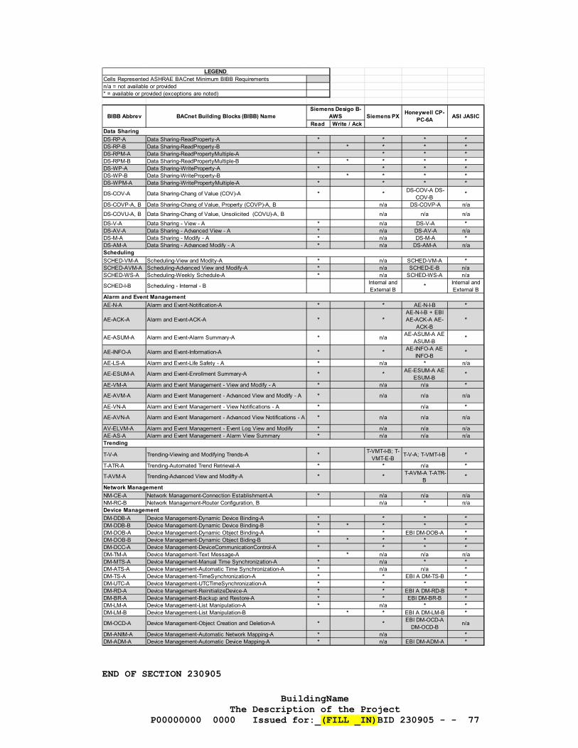
BuildingName The Description of the Project
P00000000 0000 Issued for:_(FILL _IN)BID 230905 - - 77
END OF SECTION 230905
Cells Represented ASHRAE BACnet Minimum BIBB Requirementsn/a = not available or provided
Read Write / Ack
DS-RP-A Data Sharing-ReadProperty-A * * * *DS-RP-B Data Sharing-ReadProperty-B * * * *DS-RPM-A Data Sharing-ReadPropertyMultiple-A * * * *DS-RPM-B Data Sharing-ReadPropertyMultiple-B * * * *DS-WP-A Data Sharing-WriteProperty-A * * * *DS-WP-B Data Sharing-WriteProperty-B * * * *DS-WPM-A Data Sharing-WritePropertyMultiple-A * * * *
DS-COV-A Data Sharing-Chang of Value (COV)-A * * DS-COV-A DS-COV-B
*
DS-COVP-A, B Data Sharing-Chang of Value, Property (COVP)-A, B n/a DS-COVP-A n/aDS-COVU-A, B Data Sharing-Chang of Value, Unsolicited (COVU)-A, B n/a n/a n/aDS-V-A Data Sharing - View - A * n/a DS-V-A *DS-AV-A Data Sharing - Advanced View - A * n/a DS-AV-A n/aDS-M-A Data Sharing - Modify - A * n/a DS-M-A *DS-AM-A Data Sharing - Advanced Modify - A * n/a DS-AM-A n/a
SCHED-VM-A Scheduling-View and Modity-A * n/a SCHED-VM-A *SCHED-AVM-A Scheduling-Advanced View and Modify-A * n/a SCHED-E-B n/aSCHED-WS-A Scheduling-Weekly Schedule-A * n/a SCHED-WS-A n/a
SCHED-I-B Scheduling - Internal - B Internal and External B
* Internal and External B
AE-N-A Alarm and Event-Notification-A * * AE-N-I-B *
AE-ACK-A Alarm and Event-ACK-A * *AE-N-I-B + EBI AE-ACK-A AE-
ACK-B*
AE-ASUM-A Alarm and Event-Alarm Summary-A * n/a AE-ASUM-A AE ASUM-B
*
AE-INFO-A Alarm and Event-Information-A * * AE-INFO-A AE INFO-B
*
AE-LS-A Alarm and Event-Life Safety - A * n/a * n/a
AE-ESUM-A Alarm and Event-Enrollment Summary-A * * AE-ESUM-A AE ESUM-B
*
AE-VM-A Alarm and Event Management - View and Modify - A * n/a n/a *
AE-AVM-A Alarm and Event Management - Advanced View and Modify - A * n/a n/a n/a
AE-VN-A Alarm and Event Management - View Notifications - A * n/a *
AE-AVN-A Alarm and Event Management - Advanced View Notifications - A * n/a n/a n/a
AV-ELVM-A Alarm and Event Management - Event Log View and Modify * n/a n/a n/aAE-AS-A Alarm and Event Management - Alarm View Summary * n/a n/a n/a
T-V-A Trending-Viewing and Modifying Trends-A * T-VMT-I-B; T-VMT-E-B
T-V-A; T-VMT-I-B *
T-ATR-A Trending-Automated Trend Retrieval-A * * n/a *
T-AVM-A Trending-Advanced View and Modifty-A * * T-AVM-A T-ATR-B
*
NM-CE-A Network Management-Connection Establishment-A * n/a n/a n/aNM-RC-B Network Management-Router Configuration, B n/a * n/a
DM-DDB-A Device Management-Dynamic Device Binding-A * * * *DM-DDB-B Device Management-Dynamic Device Binding-B * * * * *DM-DOB-A Device Management-Dynamic Object Binding-A * * EBI DM-DOB-A *DM-DOB-B Device Management-Dynamic Object Biding-B * * * *DM-DCC-A Device Management-DeviceCommunicationControl-A * * * *DM-TM-A Device Management-Text Message-A * n/a n/a n/aDM-MTS-A Device Management-Manual Time Synchronization-A * n/a * *DM-ATS-A Device Management-Automatic Time Synchronization-A * n/a n/a *DM-TS-A Device Management-TimeSynchronization-A * * EBI A DM-TS-B *DM-UTC-A Device Management-UTCTimeSynchronization-A * * * *DM-RD-A Device Management-ReinitializeDevice-A * * EBI A DM-RD-B *DM-BR-A Device Management-Backup and Restore-A * * EBI DM-BR-B *DM-LM-A Device Management-List Manipulation-A * n/a * *DM-LM-B Device Management-List Manipulation-B * * EBI A DM-LM-B *
DM-OCD-A Device Management-Object Creation and Deletion-A * * EBI DM-OCD-A DM-OCD-B
n/a
DM-ANIM-A Device Management-Automatic Network Mapping-A * n/a *DM-ADM-A Device Management-Automatic Device Mapping-A * n/a EBI DM-ADM-A *
LEGEND
* = available or provided (exceptions are noted)
ASI JASICSiemens PXBIBB Abbrev BACnet Building Blocks (BIBB) NameSiemens Desigo B-
AWS Honeywell CP-PC-6A
Data Sharing
Device Management
Network Management
Trending
Alarm and Event Management
Scheduling


![********************************************************** 23 21 13.23 20.pdf · division 23 - heating, ventilating, and air conditioning (hvac) section 23 21 13.23 20 [high]](https://img.pdfslide.us/doc/110x75/5b16e5fc7f8b9a686d8e97b8/-23-21-1323-20pdf.jpg)