Embed Size (px)
Citation preview

Division 2 Sitework Specifications

INDEX SITE WORKS DIVISION-2 SPECIFICATIONS PROJECT NO. 163600889
OPS 211 HUNTMAR ROAD
SECTION 02035 CONTRACTORS INFORMATION REQUEST
SECTION 02100 SITE PREPARATION
SECTION 02200 EARTHWORK
SECTION 02222 EXCAVATION, BACKFILLING AND COMPACTING FOR UTILITIES
SECTION 02223 EXCAVATION, BACKFILLING AND COMPACTING FOR PAVEMENT
SECTION 02227 AGGREGATE MATERIALS
SECTION 02260 TOPSOIL AND FINISH GRADING
SECTION 02505 GRANULAR BASE COURSE
SECTION 02511 ASPHALTIC CONCRETE PAVING
SECTION 02525 CURB AND SIDEWALKS
SECTION 02584 PAVEMENT MARKINGS
SECTION 02687 SITE GAS LINES
SECTION 02846 SIGNAGE
SECTION 02900 LANDSCAPING
SECTION 02906 PLANTING OF TREES, SHRUBS AND GROUND COVERS
SECTION 02911 TOPSOIL AND FINISH GRADING
SECTION 02933 SODDING
END OF SECTION INDEX
Page 1 of 1

Master Specification Revised 10-2000 02035-1
SECTION 02035
CONTRACTOR'S INFORMATION REQUEST PART I GENERAL
All work shall conform to the local Municipal Specifications where
conflicts exist. Applicable CSA standards will prevail where ANSI or ASTM conflict with CSA standards.
1.01 SUMMARY
A. Section Includes:
1. Administrative and procedural requirements for handling and
processing "Contractor's Information Request" (CIR).
2. "Contractor's Information Request" process diagram is
attached at the end of this Section.
3. "Contractor's Information Request" form is attached at the
end of this Section.
1.02 DEFINITION
A. Requests for Information: A formal process used during the
construction phase to facilitate communication between the
contractor and the Civil Engineering Consultant (CEC) with regard
to requests for additional information and clarification of the
intent of the Contract Documents (Drawings and Specifications).
B. Do not use "Contractor's Information Request" form during bidding.
Direct questions during bidding phase as indicated in the bid documents.
1.03 PROCEDURE
A. Conditions Requiring Clarification of the Contract Documents:
1. Contractor shall submit a "Contractor's Information Request"
to the Civil Engineering Consultant.
2. Submit "Contractor's Information Request" from Contractor's
office or field office only. "Requests for Information"
submitted directly from subcontractors or suppliers will not
be accepted.
3. Generate "Requests for Information" by one source per project
and number accordingly.
4. Submit one "Contractor's Information Request" per form.

Master Specification Revised 10-2000 02035-2
B. Civil Engineering Consultant will review CIR from the Contractor
with reasonable promptness and the Contractor will be notified in
writing of decisions made.
1. The Civil Engineering Consultant's written response to the
CIR shall not be considered as a Change Order or Change
Directive, nor does it authorize changes in the Contract Sum
or Contract Time.
C. Contractor shall maintain a log of "Requests for Information" sent
to, and responses from Civil Engineering Consultant. "Requests for
Information" log shall be sent, by Fax, every Friday to the Civil
Engineering Consultant.
D. All "Requests for Information" regarding scheduling, costing and
owner provided equipment coordination shall be directed to the
Civil Engineering Consultant.
1.04 REQUEST FOR INFORMATION FORM
A. Submit "Contractor's Information Request" on the attached
"Contractor's Information Request" form, or format accordingly on
letterhead. Civil Engineering Consultant will not respond to
requests for information unless this form or format is utilized.
B. Where submittal form or format does not provide space needed for
complete information, additional sheets may be attached.
END OF SECTION 02035

CONTRACTOR'S INFORMATION REQUEST
DATE: CIR NO:
TO:
FROM:
(General Contractor)
PROJECT: (City, Province)
Store # CPM Project #
SPECIFICATION SECTION: (Project Superintendent)
DWG. NO: (Job Site Fax Number)
DETAIL NO:
INFORMATION REQUESTED:
Requested by:
REPLY:
Master Specification Revised 10-2000 02035-3

Master Specification Revised 10-2000 02100-1
SECTION 02100
SITE PREPARATION
PART 1 GENERAL
A. General Conditions, Supplementary Conditions and Division 01 apply
to this Section.
B. All work shall conform to the local Municipal Specifications where conflicts exist. Applicable CSA standards will prevail where ANSI or ASTM conflict with CSA standards.
1.01 SECTION INCLUDES:
A. Cleaning site of debris, grass, trees and other plant life in
preparation for site or building excavation work.
B. Protection of existing structures, trees or vegetation indicated on the contract documents to remain.
C. Stripping topsoil from areas that are to be incorporated into the
limits of the project and where so indicated on the construction drawings.
1.02 RELATED SECTIONS
A. Section 02050 - Demolition
B. Section 02070 - Selective Demolition
C. Section 02200 - Earthwork
D. Section 02270 - Slope Protection and Erosion Control
E. Construction Drawings
F. Supplementary Specification No. 1
G. Occupational Health and Safety Act and Regulations for
Construction Projects.
1.03 ENVIRONMENTAL REQUIREMENTS
A. Construct temporary erosion control systems as shown on the plans
or as directed by the engineer to protect adjacent properties and water resources from erosion and sedimentation.
B. In the event that the site works on this project will be under the
jurisdiction of a Municipal Topsoil Preservation by-law,
Conservation Authority or Ministry of Natural Resources work permits, etc., the Contractor is responsible for ensuring compliance with the applicable regulations throughout the entire
construction period. The permits require Erosion and Sedimentation Control Measures to be in place during construction and include monitoring of storm water flows during construction.
C. The contractor shall be totally responsible for conducting the
stormwater management and site stabilization practices in
Master Specification Revised 10-2000 02100-2
accordance with the Topsoil Preservation, Conservation Authority
or Ministry of Natural Resources work permits and for any enforcement action taken or imposed by Federal, Provincial or Municipal agencies, including the cost of fines, construction
delays and remedial actions resulting from the contractors failure to comply with all provisions of the applicable permits.
1.04 PROJECT CONDITIONS
A. Conditions existing at time of inspection for bidding purposes
will be maintained by owner in so far as practical.
B. Variations to conditions or discrepancy in actual conditions as
they apply to site preparation operations are to be brought to the attention of the Civil Engineering Consultant prior to the commencement of any site work.
PART 2 PRODUCTS
Off-site materials shall be transported to project using well maintained
and operating vehicles. Once on site, transporting vehicles shall stay on designated haul roads and shall at no time endanger improvements by rutting, overloading, or pumping.
PART 3 EXECUTION
3.01 PREPARATION
Verify that existing plant life and clearing limits are clearly tagged,
identified and marked in such a manner as to insure their safety throughout construction operations.
3.02 PROTECTION
A. Locate and identify existing utilities that are to remain and
protect them from damage.
B. Protect trees, plant growth and features designated to remain as
final landscape.
C. Conduct operations with minimum interference to public or private accesses and facilities. Maintain access and egress at all times
and clean or sweep any roadways daily or as required by the governing authority. At such times as deemed necessary by the owner, dust control shall be provided with sprinkling systems or
equipment provided by the contractor.
D. Protect bench marks, property corners and all other survey monuments from damage or displacement. If a marker needs to be removed it shall be referenced by a licensed land surveyor and
replaced, as necessary, by the same licensed surveyor.
E. Provide traffic control as required, in accordance with local
municipal requirements.

Master Specification Revised 10-2000 02100-3
3.03 CLEARING
A. Clear all areas within the site boundary as well as any offsite
servicing areas required for complete site construction and
execution of work.
B. Unless otherwise indicated on the drawings, remove trees, stumps, shrubs, grass, other vegetation, improvements, boulders, asphalt, concrete rubble, tires, wood, fence and any other redundant
materials, or obstructions interfering with installation of new construction. Removal includes digging out stumps and roots. Depressions caused by clearing and grubbing operations are to be
filled to subgrade elevation to avoid water ponding. Satisfactory fill material shall be placed in horizontal layers not exceeding 200 mm loose depth, and thoroughly compacted per fill requirements
of this section and Section 02200.
C. Remove grass, trees, plant life, stumps and all other construction debris from the site to a dump site that is suitable for handling
such material according to applicable Local, Provincial and Federal laws and regulations.
3.04 TOPSOIL EXCAVATION
A. Strip topsoil from areas that are to be filled, excavated,
landscaped or re-graded to such a depth that it prevents
intermingling with underlying subsoil or questionable material.
B. Cut heavy growths of grass from areas before stripping and remove with the rest of the cleared vegetative material.
C. Topsoil shall consist of organic surficial soil found in depth of
not less than 150 mm. Satisfactory topsoil is reasonably free of
subsoil, clay lumps, stones and other objects over 50 mm in diameter, weeds, roots, and other objectionable material.
D. Stockpile topsoil in storage piles in areas shown or where
directed. Construct storage piles to freely drain surface water.
Cover storage piles as required to prevent windblown dust. Dispose of unsuitable topsoil as specified for waste material, unless otherwise specified by owner. Excess topsoil shall be
removed from the site by the Contractor unless specifically noted otherwise on the Drawings.
3.05 DUST CONTROL
A. The Contractor will be responsible for all dust control in
accordance with local municipal standards, bylaws and requirements
including supply and placement of water, calcium, etc.
END OF SECTION 02100

Master Specification Revised 10-2000 02200-1
SECTION 02200
EARTHWORK
PART 1 GENERAL
A. General Conditions, Supplementary Conditions and Division 01 apply
to this Section.
B. All work shall conform to the local Municipal Specifications where conflicts exist. Applicable CSA standards will prevail where ANSI or ASTM conflict with CSA standards.
1.01 SECTION INCLUDES
A. Protection, modification and/or installation of utilities as
sitework progresses paying particular attention to grade changes and any necessary staging of work.
B. Cutting, filling and grading to required lines, dimensions,
contours and proposed elevations for proposed improvements.
C. Scarifying, compaction, drying and removal of unsuitable material
to ensure proper preparation of areas for fills or proposed
improvements. 1.02 RELATED SECTIONS
A. Section 02050 - Demolition
B. Section 02070 – Selective Demolition
C. Section 02100 - Site Preparation
D. Section 02221 - Excavation, Backfill and Compaction for Structures
E. Section 02222 - Excavation, Backfill and Compaction for Utilities
F. Section 02223 - Excavation, Backfill and Compaction for Pavement
G. Section 02227 - Aggregate Materials
H. Section 02229 - Rock Removal
I. Section 02245 - Soil Stabilization
J. Section 2270 - Slope Protection and Erosion Control
K. Section 02900 - Landscaping
L. Geotechnical Report (if available) for boring locations and
findings of subsurface materials and conditions.
M. Construction Drawings

Master Specification Revised 10-2000 02200-2
N. Architectural Plans and Specifications as they relate specifically
to the earthwork beneath the buildings, where the architectural requirements are more stringent than the civil requirements
O. Supplementary Specification No. 1.
1.03 REFERENCE STANDARDS
A. American Society for Testing and Materials (ASTM) latest edition.
B. American Association of State Highway and Transportation Officials (AASHTO) latest edition
C. Local Municipal Standards and Specifications.
D. Occupational Health and Safety Act and Regulation for Construction
Projects. 1.04 QUALITY ASSURANCE
A. Independent Testing Laboratory selected and paid by owner, shall
be retained to perform construction testing on site based on the following:
1. Building Subgrade Areas, including 3.0 m Outside Exterior
Building Lines: In cut areas, not less than one compaction test for every 235 square metres. In fill areas, same rate of testing for each 200 mm lift (measured loose).
2. Areas of Construction exclusive of building subgrade: In cut
areas, not less than one compaction test for every 950
square metres. In fill areas, same rate of testing for each 200 mm lift (measured loose).
B. If compaction requirements are not complied with at any time
during construction process, remove and recompact deficient areas
until proper compaction is obtained at no additional expense to owner.
C. In all areas to receive pavement, a CBR (or LBR) test shall be
performed for each type of material imported from off-site.
D. The following tests shall be performed on each type of on-site or
imported soil material used as compacted fill as part of construction testing requirements.
1. Moisture and Density Relationship: ASTM D 698 or ASTM D1557.
2. Mechanical Analysis: AASHTO T-88
3. Plasticity Index: ASTM D 4318
E. Field density tests for in-place materials shall be performed
according to one of the following standards as part of construction testing requirements.
1. Nuclear Method: ASTM D 2922 (Method B-Direct Transmission)
F. Independent Testing Laboratory shall prepare test reports that
indicate test location, elevation data, and test results. Owner, Engineer/Architect, and Contractor shall be provided with copies

Master Specification Revised 10-2000 02200-3
of reports within 96 hours of time test was performed. In event
that any test performed fails to meet these Specifications, owner and contractor shall be notified immediately by independent testing laboratory.
G. All costs related to re-testing due to failures shall be paid for by the
contractor at no additional expense to owner. Owner reserves the right to employ an Independent Testing Laboratory and to direct
any testing that is deemed necessary. Contractor shall provide free access to site for testing activities.
1.05 SUBMITTALS
A. Submit a sample of each type of off-site fill materials that is to
be used at the site in an airtight, 5 kg container for the testing laboratory.
B. Submit the name of each material supplier and specific type and
source of each material. Any change in source throughout the job requires approval of the owner or engineer.
C. For use of fabrics or geogrids, a design shall be submitted for
approval by the Owner. PART 2 PRODUCTS
2.01 MATERIALS
A. Excavated and re-used material for subsoil fill as specified
herein.
B. Aggregate fill as specified in Section 02227.
C. Imported subsoil material approved by the owner and specified herein.
D. Topsoil fill as specified in Section 02100.
E. Acceptable stabilization fabrics and Geogrids or Equivalents as
approved by the Geotechnical Engineer as specified in contract documents.
F. Filter/Drainage Fabrics as specified in contract documents, or
equivalent as approved by the Geotechnical Engineer. 2.02 EQUIPMENT
Off-site materials shall be transported to project using well maintained
and operating vehicles. Once on site, transporting vehicles shall stay on designated haul roads and shall at no time endanger improvements by rutting, overloading, or pumping.

Master Specification Revised 10-2000 02200-4
PART 3 EXECUTION 3.01 PREPARATION
A. Identify required lines, levels, contours and datum
Survey stakes with exact elevations must be positioned to identify the engineered fill areas and the proposed finished fill grade.
B. Locate and identify existing utilities that are to remain and
protect them from damage.
C. Notify utility companies to remove and/or relocate any utilities that are in conflict with the proposed improvements.
D. Protect plant life, lawns, fences, existing structures, sidewalks,
paving and curbs from excavating equipment and vehicular traffic.
E. Protect benchmarks, property corners and all other survey
monuments from damage or displacement. If a marker needs to be removed it shall be referenced by a licensed land surveyor and
replaced, as necessary, by the same.
F. Remove from site material encountered in grading operations that, in opinion of owner or owners representative, is unsuitable or undesirable for backfilling, subgrade or foundation purposes and
all surplus fill materials. Dispose of in a manner satisfactory to owner. Backfill areas with layers of suitable material and compact as specified.
G. Prior to placing fill in low areas, such as previously existing
creeks, ponds, or lakes, perform following procedures. All work must be performed per applicable legislation/regulation and as approved by Engineer.
1. Drain water out by gravity with ditch having flow line
lower than lowest elevation in low area. If drainage cannot be performed by gravity ditch, use adequate pump to obtain same results.
2. After drainage of low area is complete, remove mulch, mud,
debris, and other unsuitable material by using acceptable equipment and methods that will keep natural soils
underlying low areas dry and undisturbed.
3. If proposed for fill, all muck, mud, and other materials removed from above low areas shall be dried on-site by spreading in thin layers for observation by owner or owners
representative. Material shall be inspected and, if found to be suitable for use as fill material, shall be incorporated into lowest elevation of site filling
operation, but not under the building area or within 3.0 m
of perimeter of building pad or paving subgrade. If, after observation by owner or owners representative, material is
found to be unsuitable, all unsuitable material shall be removed from site.
4. In the event of a site material deficit, co-ordinate, and
import fill from off site and include all costs as specified
herein.

Master Specification Revised 10-2000 02200-5
The fill is not to be brought to the site until such time that a sample has been reviewed and tested by qualified engineers, with respect to suitability of material for
filling purposes intended, and it is certified that the material is free of chemical or toxic contaminants.
3.02 EXCAVATION FOR FILLING AND GRADING
A. Classification of Excavation: Contractor by submitting bid
acknowledges that he has investigated the site to determine type,
quantity, quality, and character of excavation work to be performed. All excavation to comply with requirements of the OHSA for construction projects.
B. Perform excavation using capable well maintained equipment and
methods acceptable to owner and governing agencies.
C. When performing grading operations during periods of wet weather, provide adequate drainage and ground water management to control
moisture of soils.
D. Shore, brace, and drain excavations as necessary to maintain safe, secure, and free of water at all times.
E. Excavated material containing rock or stone greater than 150 mm in
largest dimension is unacceptable as fill within the proposed
building and paving area.
F. Rock or stone less than 150 mm in largest dimension is acceptable as fill up to 600 mm below the surface of proposed subgrade when mixed with suitable material.
G. Rock or stone less than 50 mm in largest dimension and mixed with
suitable material is acceptable as fill within the upper 600 mm of proposed subgrade.
3.03 FILLING AND SUBGRADE PREPARATION
A. Fill areas to contours and elevations shown with unfrozen
materials.
B. Place fill in continuous lifts specified herein.
C. Refer to Section 02221 for filling requirements for structures.
D. Refer to Section 02222 for filling requirements for utilities.
E. Refer to Section 02223 for filling requirements for pavements.
F. Areas exposed by excavation or stripping and on which subgrade
preparations are to be performed shall be scarified to minimum depth of 200 mm and compacted to minimum of 98% SPMDD, unless
otherwise specified in the contract documents or drawings at a moisture content of not less than 1% below and not more than 3% above, or as directed by the Geotechnical Engineer, the optimum
moisture content. These areas shall then be proofrolled to detect any areas of insufficient compaction. Proofrolling shall be accomplished by making a minimum of two (2) complete passes with a
fully-loaded tandem-axle dump truck, or approved equivalent, in each of the two perpendicular directions under the supervision and

Master Specification Revised 10-2000 02200-6
direction of a field geotechnical engineer. Areas of failure shall
be excavated and re-compacted as stated above.
G. Fill materials used in preparation of subgrade shall be placed in lifts or layers not to exceed 200 mm loose measure and compacted
to a minimum density of 98% SPMDD unless otherwise specified in the contract documents or drawings at a moisture content of not less than 1% below and not more than 3% above the optimum moisture
content or as directed by the Geotechnical Engineer.
H. Material imported from off-site shall have a CBR (California Bearing Ratio) or LBR (Limerock Bearing Ratio) value equal to or above the pavement design subgrade CBR or LBR value indicated on
the Drawings, and subject to acceptance by the Engineer. 3.04 MAINTENANCE OF SUBGRADE
A. Finished subgrades shall be verified to ensure proper elevation
and conditions for construction above subgrade.
B. Protect subgrade from excessive wheel loading during construction, including concrete trucks and dump trucks.
C. Remove areas of finished subgrade found to have insufficient
compaction density to depth necessary and replace in a manner that will comply with compaction requirements by use of material equal to or better than best subgrade material on site. Surface of
subgrade after compaction shall be hard, uniform, smooth, stable, and true to grade and cross-section.
3.05 FILTER FABRIC
A. The filter material shall be as described in the appropriate
Appendices and/or Drawings or an equal alternative and the
Contractor is required to have a sample of the material delivered to the site for approval prior to commencing the installation.
Place filter material in the manner outlined by the manufacturer or as specified. Adjacent sections of filter cloth shall be
overlapped a minimum of 600 mm unless otherwise noted. 3.06 RIP-RAP
A. Place rip-rap in all areas where indicated on the Drawings. The
stone for rip-rap shall consist of fieldstone or rough unhewn quarry stone as nearly uniform, in section as is practical. The
stones shall be dense, resistant to the action of air and water, and suitable in all aspects for the purpose intended
B. Slopes and other areas to be protected shall be dressed to the
line and grade shown on the plans prior to the placing of rip-rap. Contractor shall undercut the areas to receive rip-rap to an
elevation equal to the final elevation less the average diameter of the stones before placing the rip-rap.
C. Filter fabric and bedding stone shall be installed prior to the
placement of the stones if so indicated on the drawings. The bedding stone shall be quarried and crushed angular limestone, or approved equivalent, in accordance with Section 02227 and shall be

Master Specification Revised 10-2000 02200-7
150 mm in depth. Filter fabric shall be as specified herein and
as detailed on the plans.
D. Stones shall be placed so that the greater portion of their weight is carried by the earth and not by the adjacent stones. The stones
shall be placed in a single layer with close joints. The upright areas of the stone shall make an angle of approximately 90-degree with the embankment slope. The courses shall be placed from the
bottom of the embankment upward, the larger stones being placed in the lower courses. Open joints shall be filled with spalls. Stones shall be embedded in the embankment as necessary to present a
uniform top surface such that the variation between tops of adjacent stones shall not exceed 75 mm.
3.07 FINISH GRADING
A. Grade all areas where finish grade elevations or contours are
indicated on Drawings, other than paved areas and buildings,
including excavated areas, filled and transition areas, and
landscaped areas. Graded areas shall be uniform and smooth, free from rock, debris, or irregular surface changes. Finished subgrade surface shall not be more than 30 mm above or below established
finished subgrade elevation, and all ground surfaces shall vary uniformly between indicated elevations. Finish ditches shall be graded to allow for proper drainage without ponding and in a
manner that will minimize erosion potential. For topsoil application, refer to Section 02900 Landscaping.
B. Correct all settlement and eroded areas within one year after date
of completion at no additional expense to owner. Bring grades to proper elevation. Replant or replace any grass, shrubs, bushes, or other vegetation that appears dead, dying or disturbed by
construction activities. Refer to Section 02270 for slope protection and erosion control.
C. Refer to Section 02245 for soil stabilization using lime, cement,
fly ash and geotextile fabric methods for subbase materials. 3.08 DUST CONTROL
A. The Contractor will be responsible for all dust control in
accordance with local municipal standards, bylaws and requirements
including supply and placement of water, calcium, etc. 3.09 ROCK EXCAVATION (See Section 02229 Rock Removal)
END OF SECTION 02200
Master Specification Revised 10-2000 02222-1
SECTION 02222
EXCAVATION, BACKFILLING AND COMPACTING FOR UTILITIES PART 1 GENERAL
A. General Conditions, Supplementary Conditions and Division 01 apply
to this Section.
B. All work shall conform to the local Municipal Specifications where
conflicts exist. Applicable CSA standards will prevail where ANSI or ASTM conflict with CSA standards.
1.01 SECTION INCLUDES
A) Excavating trenches for the installation of utilities
B) Backfilling trench with bedding material as specified and
indicated and filling trench with suitable material to proposed
subgrade.
C) Compacting backfill materials in an acceptable manner
D) Borings and casings under roads
1.02 RELATED SECTIONS
A) Section 02050 - Demolition
B) Section 02070 - Selective Demolition
C) Section 02200 - Earthwork
D) Section 02227 - Aggregate Materials
E) Section 02229 - Rock Removal
F) Section 02605 - Sewer Structures
G) Section 02660 - Water Distribution Systems
H) Section 02720 - Storm Sewer Systems
I) Section 02730 - Sanitary Sewer Systems
J) Section 02811 - Landscape Irrigation
K) Geotechnical report (if available) for boring locations and
findings of subsurface materials and conditions
L) Construction Drawings
M) Supplementary Specifications No.1.
1.03 REFERENCE STANDARDS

Master Specification Revised 10-2000 02222-2
A. American Water Works Association Latest Edition
B. American Association of State Highway and Transportation Officials (AASHTO) latest edition
C. American Society for Testing and Materials (ASTM) latest edition.
D. Occupational Health and Safety Act and Regulations for Construction Projects.
E. Local Municipal Standards and Specifications.
1.04 QUALITY ASSURANCE
Independent testing laboratory selected and paid by owner shall be retained to perform construction testing on backfilling operations as specified in Section 02200 and as stated herein.
1.05 SUBMITTALS
A. Shop Drawings or details pertaining to Site Utilities are not
required unless required by regulatory authorities or unless use of materials, methods, equipment, or procedures are contrary to Drawings or these specifications are proposed. Do not perform work
until required shop drawings have been accepted by Owner.
B. The Contractor shall contact all utility companies and determine if additional easements will be required to complete the project. Contractor shall provide written confirmation of the status of all
easements to the Owner's Construction Manager at the time of the preconstruction conference or no later than 90 days prior to the project possession date.
C. Submit a sample of each type of offsite fill material that is to
be used in backfilling in an air-tight, 5 kg container for the testing laboratory or submit a gradation and certification of the
aggregate material that is to be used to the testing laboratory
for review. 1.06 PROJECT RECORD DOCUMENTS
Accurately record actual locations of all subsurface utilities, structures and obstructions encountered.
PART 2 PRODUCTS
2.01 MATERIALS
A. Bedding Material: Processed sand and gravel free from clay lumps,
organic, or other deleterious material, and complying with
gradation requirements of the local Municipality.
B. Backfill material from site as specified in Section 02200 and
approved by the owner or owner's representative.
C. Backfill material from offsite as specified in Section 02200 and approved by the owner or owner's representative.
D. Steel Casing Pipe: Comply with AWWA C-200, minimum grade B, size
and wall thickness as indicated on Drawings.
Master Specification Revised 10-2000 02222-3
E. Acceptable Stabilization Fabrics and Geogrids as specified in Contract Documents or equivalent as approved by Engineer.
F. The filter material shall be as described in the appropriate
Appendices and/or Drawings or an equal alternative and the
Contractor is required to have a sample of the material delivered to the site for approval prior to commencing the installation.
PART 3 EXECUTION
3.01 PREPARATION
A. Set all lines, elevations, and grades for utility and drainage
system work and control system for duration of work, including careful maintenance of bench marks, property corners, monuments,
or other reference points.
B. Maintain in operating condition all existing utilities, active
utilities and drainage systems encountered in utility installation. Repair any surface or subsurface improvements shown
on Drawings.
C. Verify location, size, elevation, and other pertinent data
required to make connections to existing utilities and drainage
systems prior to commencing construction, and as indicated on
Contract documents. Report any variation from design drawings to
the Civil Engineering Consultant immediately. Contractor shall
comply with local codes and regulations.
D. Over excavate and properly prepare areas of subgrade that are not
capable of supporting the proposed systems. These areas shall be stabilized by using acceptable filter fabrics and/or additional bedding material placed and compacted as specified.
E. Design and install dewatering systems that will be required to
construct the proposed utilities in a manner that is described
herein. 3.02 EXCAVATION
A. The local utility companies shall be contacted before excavation
shall begin. Dig trench at proper width and depth for laying pipe,
conduit, or cable. Cut trench banks vertical if possible and
remove stones from bottom of trench as necessary to avoid point-bearing. Over excavate wet or unstable soil, if encountered, from trench bottom as necessary to provide suitable base for continuous and uniform bedding.
B. All trench excavation side walls greater than 1.2 m in depth shall
be sloped, shored, sheeted, braced or otherwise supported by means of sufficient strength to protect the workmen within them in
accordance with the applicable rules and regulations established for construction by the Ministry of Labour, Occupational Health
and Safety Act (OHSA), and by local ordinances. Lateral travel
distance to an exit ladder or steps shall not be greater than specified in the OHSA.
C. Perform excavation as indicated for specified depths. During
excavation, stockpile materials suitable for backfilling in
orderly manner far enough from bank of trench to avoid overloading, slides, or cave-ins.

Master Specification Revised 10-2000 02222-4
D. Remove excavated materials not required or not suitable for
earthworks, backfill or embankments and waste to the contractors approved disposal site. Any structures discovered during excavation(s) shall also be disposed.
E. Prevent surface water from flowing into trenches or other
excavations by temporary grading or other methods, as required. Remove accumulated subsurface water in trenches or other
excavations by pumping, deep wells, trench backfilling or other acceptable methods.
F. Open cut excavation with trenching machine or backhoe. Where
machines other than ladder or wheel-type trenching machines are
used, do not use clods for backfill. Dispose of unsuitable material and provide other suitable material at no additional cost to Owner.
G. Accurately grade trench bottom to provide uniform bearing and
support for each section of pipe on bedding material at every point along entire length, except where necessary to excavate for bell holes, proper sealing of pipe joints, or other required
connections. Dig bell holes and depressions for joints after trench bottom has been graded. Dig no deeper, longer, or wider than needed to make joint connection properly.
H. Trench width requirements below the top of the pipe shall not be
less than 300 mm nor more than 450 mm wider than outside surface of any pipe or conduit that is to be installed to designated elevations and grades. All other trench width requirements for
pipe, conduit, or cable shall be the least practical width that will allow for proper compaction of trench backfill, or as specified by pipe manufacturer.
I. Trench depth requirements measured from finished grade or paved
surface shall meet the following requirements or applicable codes and ordinances:
1. Water Mains: Depths, elevations, and grades as indicated on
Drawings.
2. Sanitary Sewer: Depths, elevations, and grades as indicated on Drawings.
3. Storm Sewer: Depths, elevations, and grades as shown on
Drawings.
4. Electrical Conduits: 600 mm minimum to top of conduit or as required by the local utility company requirements, whichever is deeper.
5. TV Conduits: 450 mm minimum to top of conduit or as required
by the local utility company, whichever is deeper.
6. Telephone Conduits: 450 mm minimum to top of conduit, or as required by the local utility company, whichever is deeper.
7. Gas Mains and Service: 750 mm minimum to top of pipe, or as
required by the local utility company, whichever is deeper.
J. The Contractor is required to backfill all trenches in the
municipal right-of-way as per Local Municipality Standards.
Master Specification Revised 10-2000 02222-5
K. The Contractor shall schedule his work so that there will be
no open excavation adjacent to a lane carrying traffic
overnight and on non-working days. Excavations within ten
metres (10 m) of lanes carrying vehicular or pedestrian
traffic shall be backfilled with the specified material up
to subgrade and compacted prior to closing down daily
operations.
The above is subject to all additional restrictions placed
by the Local Municipalities or Governing Authority. All associated costs will be deemed included in the lump sum price.
3.03 PIPE BEDDING
A. The Contractor is required to notify the Engineer of the source of
granular material immediately upon award of this contract. No
service installation is to commence until samples have been obtained by the material testing company and test results reviewed
and approved by the Local Municipality or the Engineer. Any services installed prior to this approval may be ordered removed and replaced by the Engineer at no cost to the Owner.
No payment will be made or time allowed due to delays.
B. The Contractor shall use normal bedding materials when installing
the sewer in a dry, stable trench condition. If required, in wet conditions (as previously identified in the geotechnical report), the Contractor may use substitute bedding materials if approved by
the Geotechnical Engineer. Use of clear stone shall not be permitted unless wrapped with a filter fabric to perform as a separator between the stone and the native soil and between the
stone and other bedding materials. Where the invert of the sewer is underlain by non-engineered fill or other unsuitable materials, these materials are to be excavated and the Contractor shall
install a well graded granular material as approved by the Engineer.
C. Accurately cut trenches for pipe or conduit that is to be
installed to designated elevations plus depth of bedding material below bottom of pipe and to width as specified. Place specified bedding material, compact in bottom of trench, and accurately
shape to conform to lower portion of pipe barrel.
D. Place geotextile fabric as specified on the plans and
specifications. 3.04 BACKFILLING
A. Criteria: Trenches shall not be backfilled until required tests
are performed and the utility systems comply with and are accepted by applicable governing authorities. Backfill trenches as specified. If improperly backfilled, reopen to depth required to obtain proper compaction. Backfill and compact, as specified, to properly correct condition in an acceptable manner.
Master Specification Revised 10-2000 02222-6
B. Backfilling: After pipe or conduit has been installed, bedded, and
tested as specified, backfill trench or structure excavation with specified material placed in 200 mm maximum loose lifts.
C. Backfill trenches to the contours and elevations shown on the
plans with unfrozen materials.
D. Systematically backfill to allow maximum time for natural settlement. Do not backfill over porous, wet, frozen or spongy subgrade surfaces.
3.05 COMPACTION
A. Exercise proper caution when compacting immediately over top of
pipes or conduits. Water jetting or flooding is not permitted as a method of compaction unless directed or approved by the Engineer.
B. Native backfill materials are to be brought to not less than 1%
and not more than 3% or as directed the Geotechnical Engineer of
optimum moisture content and compacted to 95% of maximum density
up to the level of subgrade elevations.
C. All materials used for backfill shall comply with the requirements of Section 02200.
3.06 BORINGS AND CASINGS UNDER ROADS, HIGHWAYS AND RAILROAD CROSSINGS
A. When indicated by Drawings and specifications, all street, road,
highway, or railroad crossings for utility mains installed by the jacking and boring method shall be in accordance with contract
specifications and governing authorities.
B. Excavation of approach pits and trenches within right-of-way of street, road, highway, or railroad shall be of sufficient distance
from paving or railroad tracks to permit traffic to pass without
interference. Tamp backfill for approach pits and trenches within right-of-way in layers not greater than 150 mm thick for entire
length and depth of trench or pit. Compact backfill to 95% of maximum density obtained at optimum moisture as determined by AASHO T 180-57, Method A. Mechanical tampers may be used after
cover of 150 mm has been obtained over top of barrel of pipe.
C. Accomplish boring operation using commercial type boring rig and hole shall be bored to proper alignment and grade and within 50 mm of same diameter as largest outside joint diameter of pipe
installed. Install pipe in hole immediately after bore has been made, and in no instance shall hole be left open while unattended.
D. In event subsurface operations result in failure or damage to
pavement within one year of construction, Contractor shall make
necessary repairs to pavement at no additional cost to Owner. In event paving cracks on either side of pipe line or is otherwise
disturbed or broken due to construction operations, Contractor
shall repair or replace disturbed or broken area at no additional expense to the Owner.
E. Clean and prime interior and exterior of casing pipe; and line
with two coats of asphalt in accordance with project
specifications.
Master Specification Revised 10-2000 02222-7
F. Butt weld steel casing. Welds shall be full penetration single
butt-welds in accordance with CSA requirements.
G. Install casing and utility pipe with end seals, vent pipe, and
other special equipment in accordance with approval agency/utility
specifications.
3.07 ROCK EXCAVATION (See Section 02229 Rock Removal)
3.08 TRANSPORTATION
Off-site materials shall be transported to the project using well
maintained and operating vehicles. Once on the job site, all
transporting vehicles shall stay on designated haul roads and shall at
no time endanger any of the improvements by rutting, overloading or
pumping the haul road.
END OF SECTION 02222

Master Specification Revised 10-2000 02223-1
SECTION 02223
EXCAVATION, BACKFILLING AND COMPACTING FOR PAVEMENT PART 1 GENERAL
A. General Conditions, Supplementary Conditions and Division 01 apply
to this Section.
B. All work shall conform to the local Municipal Specifications where conflicts exist. Applicable CSA standards will prevail where ANSI or ASTM conflict with CSA standards.
1.01 SECTION INCLUDES
A. Excavate to line, grade and configuration as shown in the plans
and specifications for proposed and future pavement areas.
B. Fill to line, grade and configuration as shown in the plans and specifications for proposed and future pavement areas.
C. Compacting fill materials in an acceptable manner as stated
herein. 1.02 RELATED SECTIONS
A. Section 02200 - Earthwork
B. Section 02227 - Aggregate Materials
C. Section 02229 - Rock Removal
D. Section 02245 - Soil Stabilization
E. Section 02505 - Paving Base Course
F. Section 02511 - Asphaltic Concrete Paving
G. Section 02520 - Portland Cement Concrete Paving
H. Section 02525 - Curbs and Sidewalks
I. Geotechnical Report (if available) for Boring Locations and
Findings of Subsurface Materials and Conditions.
J. Construction Drawings
K. Supplementary Specification No. 1.
Master Specification Revised 10-2000 02223-2
1.03 REFERENCE STANDARDS
A. American Society for Testing and Materials (ASTM) latest edition.
B. American Association of State Highway and Transportation Officials (AASHTO) latest edition
C. Local Municipal Standards and Specifications.
D. Occupational Health and Safety Act and Regulation for Construction
Projects.
E. Refer to Section 02200 for additional reference standards.
1.04 QUALITY ASSURANCE
Independent testing laboratory selected and paid by owner shall be retained to perform construction testing on filling operations and
subgrade analysis as specified in Section 02200 and as stated herein. 1.05 SUBMITTALS
A. Shop drawings or details pertaining to excavating and filling for
pavement are not required unless otherwise shown on the drawings or specifications or if contrary procedures to the project
documents are proposed.
B. Submit a sample of each type of off-site fill material that is to be used in backfilling in an air-tight, 5 kg container for the testing laboratory or submit a gradation and certification of the
aggregate material that is to be used to the testing laboratory for review.
PART 2 PRODUCTS
2.01 MATERIALS
A. Fill material from on-site as specified in Section 02200 and
approved by the owner or owners representative.
B. Fill material from off-site as specified in Section 02200 and
approved by the owner or owners representative.
C. Aggregate material as specified in Section 02227.
D. Acceptable stabilization fabrics and geogrids as specified in contract document or equivalent approved by Engineer.
2.02 EQUIPMENT
Off-site materials shall be transported to project using well maintained
and operating vehicles. Once on site, transporting vehicles shall stay
on designated haul roads and shall at no time endanger improvements by rutting, overloading, or pumping.

Master Specification Revised 10-2000 02223-3
PART 3 EXECUTION 3.01 PREPARATION
A. Identify all lines, elevations and grades necessary to construct
pavements, curb and gutter, bases, walkways and roadways as shown
in the plans and specifications.
B. Carefully protect benchmarks, property corners, monuments or other reference points. Should any markers, etc. need to be removed, it shall be referenced by a licensed land surveyor and replaced as
necessary by same.
C. Locate and identify all site utilities that have previously been installed and may be in danger of damage by grading operations.
D. Locate and identify all existing utilities that are to remain and
protect them from damage.
E. Over excavate and properly prepare areas of subgrade that are not capable of supporting the proposed systems. These areas shall be stabilized by using acceptable filter fabrics and/or aggregate
material placed and compacted as specified. 3.02 EXCAVATION
A. Excavate roadway and pavement areas to line and grade as shown in
the plans and specifications.
B. Engage all suitable material into the project fill areas as specified in Section 02200.
C. Unsuitable excavated material is to be disposed of in a manner and
location that is acceptable to the owner and local governing agencies.
D. Perform excavation using capable, well maintained equipment and
methods acceptable to the owner and the project document requirements.
3.03 FILLING AND SUBGRADE PREPARATION
A. Areas exposed by excavation or stripping and on which subgrade
preparations for paving are to be performed, including future
pavement areas, shall be scarified to minimum depth of 200 mm and compacted to minimum 98% SPMDD, unless otherwise specified in the contract documents or drawings at a moisture content of not less
than 1% below and not more than 3% above the optimum moisture content or as directed by the Geotechnical Engineer. These areas shall then be proofrolled to detect any areas of insufficient
compaction. Proofrolling shall be accomplished by making a minimum of two (2) complete passes with a fully-loaded tandem-axle dump
truck, or approved equivalent, in each of the two perpendicular
directions under the supervision and direction of a field geotechnical engineer. Areas of failure shall be excavated and re- compacted as stated above.
B. Fill materials used in preparation of subgrade shall be placed in
lifts or layers not to exceed 200 mm loose measure and compacted to a minimum density 98% SPMDD unless otherwise specified in the
Master Specification Revised 10-2000 02223-4
contract documents or drawings at a moisture content of not less
than 1% below and not more than 3% above the optimum moisture content.
C. Frost tapers of subgrade transitions and back of curbs must be
provided at 5:1 or as directed by the Geotechnical Engineer.
D. The following table stipulates maximum allowable values for plasticity index (PI) and liquid limit (LL) of suitable fill
materials to be used in the specified areas, unless specifically stated otherwise on the Drawings:
PI LL
*Paving Area, below upper 600 mm 20 50 *Paving Area, upper 600 mm 15 40
(*References to Depth are to Proposed Subgrade Elevations)
E. Material imported from off-site shall have a CBR (California
Bearing Ratio) or LBR (Limerock Bearing Ratio) value equal to or above the pavement design subgrade CBR or LBR value indicated on
the Contract documents. 3.04 COMPACTION
A. Maintain optimum moisture content of fill materials to attain
required compaction density.
B. All materials shall be tested in accordance with Section 02200.
C. An independent testing laboratory selected and paid by the owner,
shall be retained to perform testing on-site, in accordance with
Section 02200. D. If compaction requirements are not complied with at any time during
construction process, remove and re-compact deficient areas until
proper compaction is obtained at no additional expense to owner. 3.05 MAINTENANCE OF SUBGRADE
A. Finished subgrades shall be verified to ensure proper elevation
and conditions for construction above subgrade.
B. Protect subgrade from excessive wheel loading during construction including concrete trucks and dump trucks.
C. Remove areas of finished subgrade found to have insufficient
compaction density to depth necessary and replace in a manner that will comply with compaction requirements by use of material equal to or better than best subgrade material on-site. Surface of
subgrade after compaction shall be hard, uniform, smooth, stable, and true to grade and cross-section.

Master Specification Revised 10-2000 02223-5
3.06 FINISH GRADING
A. Finish grading shall be in accordance with Section 02200 and as
more specifically stated herein.
B. Grading of paving areas shall be checked by string line from grade
stakes set at not more than 15 m centres. Tolerances of 30 mm, more or less, will be permitted. Contractor to provide engineering and field staking necessary for verification of lines, grades, and
elevations. 3.07 ROCK EXCAVATION (See Section 02229 Rock Removal)
END OF SECTION 02223

Master Specification Revised 10-2000 02227-1
SECTION 02227
AGGREGATE MATERIALS
PART 1 GENERAL
A. General Conditions, Supplementary Conditions and Division 01 apply to this Section.
B. All work shall conform to the local Municipal Specifications where
conflicts exist. Applicable CSA standards will prevail where ANSI or ASTM conflict with CSA standards.
1.01 SECTION INCLUDES
Aggregate Materials
1.02 RELATED SECTIONS
A. Section 02050 - Demolition
B. Section 02100 - Site Preparation
C. Section 02200 - Earthwork
D. Section 02221 - Excavation, Backfill and Compaction for Structures
E. Section 02222 - Excavation, Backfill and Compaction for Utilities
F. Section 02223 - Excavation, Backfill and Compaction for Pavement
G. Section 02245 - Soil Stabilization
H. Section 02270 - Slope Protection and Erosion Control
I. Construction Drawings
J. Supplementary Specifications No.1 1.03 REFERENCE STANDARDS
A. American Association of State Highway and Transportation Officials
(AASHTO) latest edition.
B. Local Municipal Standards and Specifications.
C. Occupational Health and Safety Act and Regulation for Construction Projects.
1.04 QUALITY ASSURANCE
Tests and analysis of aggregate material will be performed in accordance
with standard ASTM and AASHTO procedures listed herein.

Master Specification Revised 10-2000 02227-2
1.05 SUBMITTALS
A. Submit in air tight containers a 5 kg sample of each aggregate or
mixture that is to be incorporated into the project to the testing
laboratory designated by the owner.
B. Submit the name of each material supplier and specific type and source of each material. Any change in source throughout the job requires approval of the owner and engineer.
C. Submit materials certificate to on-site independent testing
laboratory which is signed by material producer and Contractor, certifying that materials comply with, or exceed, the requirements
herein. PART 2 PRODUCTS
2.01 MATERIALS
A. The Contractor is required to notify the Engineer of the source of
granular material for parking facility and access roadway construction prior to placement to allow for obtaining samples and testing to confirm conformance with project requirements. No
granular material is to be placed until approval is received from the Engineer.
B. All construction and materials shall meet or exceed the
requirements of this section or noted on the drawings which pertain to paving base course design, materials, preparation, and/or execution. All materials shall be as indicated on Drawings
or Specifications and shall comply with applicable municipal specifications regarding source, quality, gradation, liquid limit, plasticity index, and mix proportioning.
C. Local availability and variances with each municipal and
provincial requirements may change the gradations and parameters of these materials. The Contractor shall indicate when submitting materials to be tested what the various applications will be.
D. Crushed concrete, rock, asphalt or other materials as specified in
the contract documents shall be suitably crushed by means of an on-site crusher only where specified in the project documents. Testing of the crushed material will be required to ensure
compliances with the applicable specifications. On-site crushed material shall only be used as directed by the Engineer.
PART 3 EXECUTION
3.01 STOCKPILING
Stockpile on-site at locations indicated by the owner in such a manner that there will be no standing water or mixing with other materials.
3.02 BORROW SITES
Upon completion of borrow operations, clean up borrow areas as indicated
on the plans in a neat and reasonable manner to the satisfaction of the property owner, the owner and the engineer.
3.03 TRANSPORTATION

Master Specification Revised 10-2000 02227-3
Off-site materials shall be transported to the project using well
maintained and operating vehicles. Once on the job site, all
transporting vehicles shall stay on designated haul roads and shall at
no time endanger any of the improvements by rutting, overloading or
pumping the haul road or finished surfaces.
END OF SECTION 02227
SECTION 02260
TOPSOIL AND FINSIH GRADING
PART 1 – GENERAL
1.01 GENERAL REQUIREMENTS
A. Division 1, General Requirements, is part of this Section and
shall apply as if repeated here.
1.02 REALATED WORK
A. Landscaping 02900
1.03 TESTING
A. Inform Landscape Architect of proposed source of topsoil to be
supplied and provide access for sampling at least 5 days prior
to commencing work.
B. Obtain Landscape Architect's initial approval of topsoil at
source.
C. Test topsoil from source prior to stripping and stockpiling,
for NPK, Mg, soluble salt content, organic matter and pH value.
1. Use 25 mm diameter sampling tube or spade and take 25
samples per hectare to full depth of top soil at random
across entire area to be stripped. Mix samples thoroughly
before
submitting for testing.
2. Submit 0.5 kg sample of topsoil to testing laboratory and
indicate intended use, type of mulches to be applied, type of
subsoil and quality of drainage. Prepare and ship sample
according to provincial regulations.
3. Determine required lime or sulphur treatment to bring pH
value of soil 5.5 to 7.5 level.
4. Submit two copies of soil analysis and recommendations for
corrections to Landscape Architect.
5. Inspection and testing of topsoil will be carried out by
testing laboratory designated by Landscape Architect.
Master Specification Revised 10-2000 02260-1
02260-2
1.04 SCHEDULING OF WORK
A. Schedule placing of topsoil and finish grading to permit
sodding or seeding operations within 2 days.
1.05 DELIVERY AND STORAGE
A. Deliver and store fertilizer lime sulphur in waterproof bags
showing bulk accompanied in writing by weight, analysis and
name of manufacturer.
PART 2 - PRODUCTS
2.01 MATERIALS
A. Imported topsoil: friable, neither heavy clay nor of very light
sandy nature containing minimum of 4% organic matter for clay
loams and 2% for sandy loams to maximum of 20% by volume. Free
from subsoil, roots, grass, weeds, toxic materials, stones,
foreign object and with an acidity range (pH) of 5.5 to 7.5.
Topsoil containing crabgrass, couchgrass or noxious weeds is
not acceptable.
B. Peatmoss: decomposed plant material, fairly elastic and
homogenous, free of decomposed colloidal residue, wood, sulphur
and iron containing minimum 60% organic matter by weight and
moisture content not exceeding 15%. Shredded particles may not
exceed 6 mm in size. Minimum pH value of peat 4.5, maximum 6.0.
C. Muskeg: partly decomposed organic matter, mostly consisting of
sphagnum moss, free of roots, branches and other debris not
sufficiently decomposed.
D. Fertilizer:
1. Complete commercial synthetic slow release fertilizer with
maximum 35% water soluble nitrogen.
2. Formulation ratio: as per test results.
E. Lime:
1. Ground agricultural limestone containing minimum 85% of
total carbonates.
2. Gradation requirements: percentage passing by weight, 90%
passing 1.0 mm sieve, 50% passing 125 micrometre seive.
3. Use lime as indicated by acidity analysis of topsoil to
bring pH to required level.

02260-3
F. Bonemeal: raw steamed bonemeal, finely ground with a minimum
analysis of 3% nitrogen and 20% phosphoric acid.
G. Sand: hard, granular sharp sand to CSA A82.56- M1976, well
washed and free of impurities, chemical or organic matter.
H. Sulphur: finely crushed agricultural elemental sulphur, free of
impurities.
I. Insulation for planters: polystyrene board to CGSB 41-GP-14a,
type 3, thickness 50 mm as indicated.
J. Drainage medium for planters: 20 mm clear, crushed stone
granular material.
K. Filter medium: mineral fibre insulation to CGSB 51-GP-11M, type
1. nominal density 12 kg/mü, thickness 25 mm, width 900 mm.
2.02 SOIL MIXTURES AND PLANTING
A. Planting soil:
1. For planting of trees, shrubs, and vines, mix topsoil with
20% peatmoss loose by volume.
B. Incorporate bonemeal into planting soil at rate of 3
kg/mü of soil mixture.
1. Soil mix for planters:
2. Use mixture of 6 parts topsoil to 3 parts peatmoss and 1
part of sand thoroughly mixed.
3. Incorporate bonemeal into soil at rate of 3 kg/mü of soil
mixture.
C. Incorporate fertilizer as required by soil analysis.
2.03 SITE MADE GROWING MEDIUM
A. Spread 50 mm of peat moss 50 mm of sawdust 100 mm of muskeg
with 100 mm of clean sandy soil over existing soil. Mix, spread
material thoroughly into top 100 mm of existing soil.
PART 3 - EXECUTION
3.01 PREPARATION
A. Grade subgrade, eliminating uneven areas and low spots,
ensuring positive drainage. Remove debris, roots, branches,
stones in excess of 50 mm diameter and other deleterious
materials. Remove subsoil that has been contaminated with oil,
02260-4
gasoline or calcium chloride. Dispose of removed materials as
directed.
B. Cultivate entire area which is to receive topsoil to depth of
100 mm. Repeat cultivation in those areas where equipment used
for hauling and spreading has compacted subgrade.
3.02 SPREADING OF TOPSOIL
A. Do not spread topsoil until Landscape Architect has inspected
and approved subgrade.
B. Spread topsoil with adequate moisture in uniform layers during
dry weather over approved, dry, unfrozen subgrade, where
planting is indicated.
C. Keep topsoil 15 mm below finished grade for sodded areas;
elsewhere bring topsoil up to finished grade.
D. Apply topsoil to the following minimum depths: 450 mm for shrub
beds.
E. Remove stones, roots, grass, weeds, construction materials,
debris and foreign non-organic objects from topsoil.
F. Manually spread topsoil around trees and plants.
3.03 SOIL AMENDMENTS
A. Apply lime, sulphur or other soil amendment at rate determined
from soil sample test.
B. Mix soil amendment well into full depth of topsoil by
cultivating or roto-tilling prior to application of fertilizer.
3.04 APPLICATION OF FERTILIZER
A. Apply fertilizer at least one week after lime application and
at least 6 days before sodding or seeding.
B. Spread fertilizer with mechanical spreaders over entire area of
topsoil at manufacturer's recommended rate of application rate
determined on basis of soil sample test rate as directed.
C. Mix fertilizer thoroughly into upper 50 mm of topsoil.
3.05 FINISH GRADING
A. Fine grade mechanically manually entire topsoiled area to
contours and elevations as indicated as directed. Eliminate
rough spots and low areas to ensure positive drainage.

02260-5
B. Planting over roof slab: maximum depth 1000 mm at tree base,
and 800 mm elsewhere.
3.06 SURPLUS MATERIAL
A. Dispose of surplus topsoil not required for fine grading and
landscaping off site at Contractors expense.
END OF SECTION 02260

Master Specification Revised 10-2000 02505-1
SECTION 02505
PAVING BASE COURSE
PART 1 GENERAL
A. General Conditions, Supplementary Conditions and Division 01 apply to this Section.
B. All work shall conform to the local Municipal Specifications where
conflicts exist. Applicable CSA standards will prevail where ANSI or ASTM conflict with CSA standards.
1.01 SECTION INCLUDES
A. Construction of Granular Base
B. Construction of Sand/Shell Base
C. Construction of Full Depth Asphalt Base
D. Construction of Hot-Mix, Hot Laid Asphalt
1.02 RELATED SECTIONS
A. Section 02100 - Site Preparation
B. Section 02200 - Earthwork
C. Section 02223 - Excavation, Backfill and Compaction for Pavement
D. Section 02227 - Aggregate Materials
E. Section 02245 - Soil Stabilization
F. Section 02511 - Asphaltic Concrete Paving
G. Section 02520 - Portland Cement Concrete Paving
H. Section 02525 - Curbs and Sidewalks
I. Section 02900 - Landscaping
J. Construction Drawings
K. Supplementary Specification No. 1
1.03 REFERENCES
A. American Society for Testing and Materials (ASTM) latest edition.
B. American Association of State Highway and Transportation Officials
(AASHTO) latest edition.
C. Local Municipal Standards and Specifications.
D. Occupational Health and Safety Act and Regulation for Construction
Projects. PART 2 PRODUCTS

Master Specification Revised 10-2000 02505-2
2.01 FILL MATERIALS
A. Submit materials certificate to on-site independent testing
laboratory which is signed by material producer and Contractor,
certifying that materials comply with, or exceed, the requirements herein.
PART 3 EXECUTION
3.01 EXAMINATION
Contractor shall verify that the subgrade has been inspected, tested and the gradients and elevations are correct, dry and properly prepared.
3.02 CONSTRUCTION
A. Perform base course construction in a manner that will drain
surface properly at all times and at the same time prevent runoff from adjacent areas from draining onto base course construction.
B. Compact base material to not less than 100% SPMDD, unless
otherwise indicated on the Drawings.
C. Granular Base: Construct to thickness indicated on Drawings. Apply in lifts or layers not exceeding 200 mm, measured loose.
D. Local standard Hot Mix, Hot Laid Asphalt Base and Surface Course:
Construct to thickness indicated on Drawings in lifts or layers
not exceeding 75 mm, measured loose. Compact to minimum 100% Marshal Density.
3.03 QUALITY ASSURANCE
A. An Independent Testing Laboratory, selected and paid by Owner,
shall be retained to perform construction testing of in-place base
courses for compliance with requirements for thickness, compaction, density and tolerance. Paving base course tolerances shall be verified (by means of as constructed survey readings on
not more than 15.0 m centers) to be not more than 15 mm above design elevation which will allow for paving thicknesses as shown in the Drawings. Contractor shall provide instruments and a
suitable benchmark where required.
B. The following minimum tests shall be performed on each type of material used as base course material:
1. Moisture and Density Relationship: ASTM D 698 or ASTM D
1557.
2. Mechanical Analysis: AASHTO T-88.
3. Plasticity Index: ASTM D-4318.
4. Base material thickness: Perform one test for each 1,900
square metres of in-place base material area.
5. Base material compaction: Perform one test in each lift for each 1,900 square metres of in-place base material area.
6. Test each source of base material for compliance with
applicable specifications.
Master Specification Revised 10-2000 02505-3
C. Field density tests for in-place materials shall be performed
according to one of the following standards as part of construction testing requirements:
1. Sand-Cone Method: ASTM D 1556.
2. Balloon Method: ASTM D 2167.
3. Nuclear Method: ASTM D 2922, Method B (Direct Transmission).
D. Independent Testing Laboratory shall prepare test reports that indicate test location, elevation data, and test results. The Owner, Engineer, and Contractor shall be provided with copies of reports within 96 hours of time test was performed. In event that any test performed fails to meet these Specifications, the Owner, Engineer and Contractor shall be notified immediately by Independent Testing Laboratory. The Owner reserves right to employ Independent Testing Laboratory and to direct any testing that is deemed by them to be necessary. Contractor shall provide free access to site for testing activities.
E. Costs related to retesting due to failure shall be paid for by
Contractor at no additional expense to Owner. 3.04 TRANSPORTATION
Off-site materials shall be transported to the project using well maintained and operating vehicles. Once on the job site, all transporting vehicles shall stay on designated haul roads and shall at
no time endanger any of the improvements by rutting, overloading or pumping the haul road.
END OF SECTION 02505

Master Specification Revised 10-2000 02511-1
SECTION 02511
ASPHALTIC CONCRETE PAVING
PART 1 GENERAL
A. General Conditions, Supplementary Conditions and Division 01 apply
to this Section.
B. All work shall conform to the local Municipal Specifications where conflicts exist. Applicable CSA standards will prevail where ANSI or ASTM conflict with CSA standards.
1.01 SECTION INCLUDES
A. Asphaltic concrete paving; surface course, binder course and base
course. 1.02 RELATED SECTIONS
A. Section 02223 - Excavation, Backfill and Compacting for Pavement
B. Section 02505 - Paving Base Course
C. Section 02520 - Portland Cement Concrete Paving
D. Section 02525 - Curbs
E. Section 02584 - Parking Lot and Roadway Marking
F. Construction Drawings
G. Occupational Health and Safety Act and Regulation for Construction
Projects. 1.03 SUBMITTALS
A. Mix Design: Before any asphaltic concrete paving is constructed,
submit actual mix design to the Owner's Construction Department
for review and/or approval. Design mix submittal shall follow the
format as indicated in the Asphalt Institute Manual MS-2, Marshall Stability Method; and shall include the type/name of the mix, gradation analysis, grade of asphalt cement used, Marshall Stability (lbs.), flow, and effective asphalt content (percent), for each material. The design shall be for a mixture listed in the current edition of the applicable specifications.
B. Material Certificates: Submit materials certificate to on-site
independent testing laboratory which is signed by material producer and Contractor, certifying that materials comply with, or
exceed, the requirements herein.
Master Specification Revised 10-2000 02511-2
1.04 PROJECT CONDITIONS
A. Weather Limitations:
1. Apply prime and tack coats when ambient temperature is above
4.5°C, and when temperature has been above 2°C for 12 hours immediately prior to application. Do not apply when base is
wet, contains excess moisture, or during rain.
2. Construct asphaltic concrete paving when atmospheric
temperature is above 4.5°C. 1.05 REFERENCES
A. Local Municipal Standards and Specifications
B. MS-2-Mix design methods for asphaltic concrete and other hot mix
types per The Asphalt Institute (AI)
C. MS-3-Asphalt Plant Manual per The Asphalt Institute (AI)
D. Hot Mix Asphalt Paving Handbook per US Army Corp of Engineers,
UN-13 (CE MP-ET)
E. MS-19-Basic Asphalt Emulsion Manual per The Asphalt Institute (AI)
F. ASTM D946 - Penetration - Graded Asphalt Cement for use in Pavement Construction
G. AASHTO M-226/ASTM D3381 Asphalt Cement
H. AASHTO M-140/ASTM D997 or AASHTO M-208/ASTM D-2397 Tack Coat
I. AASHTO M-117/ASTM D242 Mineral Filler
J. AASHTO T-245/ASTM D1559 Marshall Mix Design
PART 2 PRODUCTS
2.01 MATERIALS
A. Provide asphalt-aggregate mixture as recommended by local
authorities to suit project conditions. Use locally available
materials and gradations which meet local authority requirements and exhibit satisfactory records of previous installations.
B. Asphalt Cement: Comply with requirements of municipality or as
directed by Engineer.
C. Tack Coat: Emulsified asphalt; AASHTO M-140/ASTM D 997 or AASHTO M 208/ASTM D 2397, SS-1h, CSS-1, or CSS-1h, diluted with one part water to one part emulsified asphalt.
D. Mineral Filler: Rock or slag dust, hydraulic cement, or other
inert material complying with AASHTO M-17/ASTM D 242, if recommended by applicable state highway standards.
E. Asphalt-Aggregate Mixture: Unless otherwise noted on the Drawings,
the Design Mix shall have a minimum stability based on a 50-blow
Marshall complying with ASTM D 1559 of 1000 lb with a flow between 8 and 16.

Master Specification Revised 10-2000 02511-3
Percent bitumen by weight of total mix: 5.0 - 8.5.
Air voids: 3-6%
Percent aggregate voids filled with asphalt cement: 70 - 82%. Allowable variance of percent bitumen by weight of total mix = 0.4, or as otherwise specified.
2.02 EQUIPMENT
Maintain equipment in satisfactory operating condition and correct
breakdowns in a manner that will not delay or be detrimental to progress of paving operations.
PART 3 EXECUTION
3.01 PREPARATION
A. Remove loose material from compacted base material surface
immediately before applying prime coat.
B. Proof roll prepared base material surface to check for areas
requiring additional compaction and areas requiring removal and recompaction.
C. Do not begin paving work until deficient base material areas have
been corrected and are ready to receive paving. 3.02 APPLICATIONS
A. Tack Coat:
1. Apply to contact surfaces of previously constructed
asphaltic concrete base courses or portland cement concrete and surfaces abutting or projecting into asphaltic concrete or into asphaltic concrete pavement.
2. Apply tack coat to asphaltic concrete base course or sand
asphalt base course. Apply emulsified asphalt tack coat between each lift or layer of full depth asphaltic concrete
and sand asphalt bases and on surface of all such bases where asphaltic concrete paving will be constructed.
3. Apply emulsified asphalt tack coat in accordance with APWA
Section 2204.
4. Apply at minimum rate of 0.25 litres per square metre of
surface.
5. Allow to dry until at proper condition to receive paving.
Master Specification Revised 10-2000 02511-4
3.03 ASPHALTIC CONCRETE PLACEMENT
A. Place asphaltic concrete mixture on completed compacted subgrade
surface, spread, and strike off. Spread mixture at following
minimum temperatures or as otherwise specified:
1. When ambient temperature is between 4.5°C and 10°C, mixture
temp. = 140°C
2. When ambient temperature is between 10°C and 15°C, mixture
temp. = 137.5°C
3. When ambient temperature is higher than 15°C, mixture temp.
= 135°C
B. Whenever possible, all pavement shall be spread by a finishing
machine; however, inaccessible or irregular areas may be placed by hand methods. The hot mixture shall be spread uniformly to the required depth with hot shovels and rakes. After spreading, the
hot mixture shall be carefully smoothed to remove all segregated course aggregate and rake marks. Rakes and lutes used for hand spreading shall be of the type designed for use on asphalt
mixtures. Loads shall not be dumped faster that they can be properly spread. Workers shall not stand on the loose mixture while spreading.
C. Paving Machine Placement: Apply successive lifts of asphaltic
concrete in transverse directions with the surface course placed in the direction of surface-water flow. Place in typical strips not less than 3.0 m wide.
D. Joints: Make joints between old and new pavements, or between
successive days and work in a manner that will provide a
continuous bond between adjoining work. Construction joints shall
have same texture, density, and smoothness as other sections of asphaltic concrete course. Clean contact surfaces of all joints and apply tack coat.
3.04 ROLLING AND COMPACTION
A. The mixture, after being spread, shall be thoroughly compacted by
rolling as soon as it will bear the weight of the rollers without undue displacement. The number, weight, and types of rollers and sequences of rolling operations shall be such that the required
density and surface are consistently attained while the mixture is in a workable condition.
B. Compact mixture with hot hand tampers or vibrating plate
compactors in areas inaccessible to rollers.
C. Breakdown Rolling: Accomplish breakdown or initial rolling
immediately following rolling of joints and outside edge. Check surface after breakdown rolling, and repair displaced areas by loosening and filling with hot material.
D. Second Rolling: Follow breakdown rolling as soon as possible,
while mixture is hot. Continue second rolling until mixture has been thoroughly compacted.

Master Specification Revised 10-2000 02511-5
E. Finish Rolling: Perform finish rolling while mixture is still warm
enough for removal of roller marks. Continue rolling until roller marks are eliminated and course has attained maximum density.
F. Patching: Remove and replace paving areas mixed with foreign
materials and defective areas. Cut out such areas and fill with fresh, hot asphaltic concrete. Compact by rolling to maximum surface density and smoothness.
G. Protection: After final rolling, do not permit vehicular traffic
on pavement until it has cooled and hardened. Erect barricades to protect paving from traffic until mixture has cooled enough not to become marked.
3.05 FIELD QUALITY CONTROL
A. Independent Testing Laboratory, selected and paid by Owner, shall
be retained to perform construction testing of in-place asphaltic
concrete courses for compliance with requirements for thickness, compaction and surface smoothness. Asphaltic surface and base
courses shall be randomly cored at a minimum rate of one core for every 1,850 square metres of paving. However, no less than three cores in light duty areas and three cores in heavy duty areas
shall be obtained. Coring holes shall be immediately filled with full-depth asphalt or with concrete. Asphaltic Concrete pavement samples shall be tested for conformance with the mix design.
B. Grade Control: Establish and maintain required lines and
elevations.
C. Thickness: In-place compacted thickness shall not be less than thickness specified on the drawings. Areas of deficient paving thickness shall receive a tack coat and a minimum 25 mm overlay;
or shall be removed and replaced to the proper thickness, at the discretion of the Owner; until specified thickness of the course is met or exceeded at no additional expense to the Owner.
D. Surface Smoothness: Testing shall be performed on the finished
surface of each asphalt concrete course for smoothness, using 3.0 m straightedge applied parallel with, and at right angles to centerline of paved area. The results of these tests shall be made
available to the owner upon request. Surfaces will not be acceptable if the following 3.0 m straightedge tolerances for smoothness are exceeded.
Base Course Surface: 6 mm
Wearing Course Surface: 5 mm
E. Check surface areas at intervals necessary to eliminate ponding areas. Remove and replace unacceptable paving as directed by
Owner.
F. Compaction: Field density test for in place materials shall be
performed by examination of field cores in accordance with one of the following standards, and shall be 100% Marshall Density:
1. Bulk specific gravity of paraffin-coated specimens: ASTM
D-1188.
2. Bulk specific gravity using saturated surface-dry specimens: ASTM D-2726.
Rate of testing shall be one core per 1,850 square metres of
pavement, with a minimum of 3 cores from heavy =-duty areas and 3

Master Specification Revised 10-2000 02511-6
cores from standard-duty areas. Cores shall be cut from areas
representative of the project.
Areas of insufficient compaction shall be delineated, removed, and
replaced in compliance with the specifications at no expense to
the Owner.
3.06 TRANSPORTATION
Off-site materials shall be transported to the project using well
maintained and operating vehicles. Once on the job site, all
transporting vehicles shall stay on designated haul roads and shall at
no time endanger any of the improvements by rutting, overloading or
pumping the haul road.
END OF SECTION 02511

Master Specification Revised 10-2000 02525-1
SECTION 02525
CURB AND SIDEWALKS
PART I GENERAL
A. General Conditions, Supplementary Conditions and Division 01 apply to this Section.
B. All work shall conform to the local Municipal Specifications where
conflicts exist. Applicable CSA standards will prevail where ANSI or ASTM conflict with CSA standards.
1.01 SECTION INCLUDES
A. Combination concrete curb and gutter
B. Concrete Curb
C. Concrete Sidewalk
1.02 RELATED SECTIONS
A. Section 02100 - Site Preparation.
B. Section 02227 - Aggregate Material.
C. Section 02505 - Paving Base Course.
D. Section 02584 - Pavement Markings.
E. Section 03300 - Cast-in-place Concrete (See Architectural/Building Specifications).
F. Construction Drawings.
G. Supplementary Specification No. 1
1.03 REFERENCES
A. American Concrete Institute (ACI) latest edition.
304R Recommended Practice for Measuring, Mixing, Trensporting, and Placing Concrete
308 Standard Practice for Curing Concrete
B. American Society for Testing and Materials (ASTM) latest edition A 615 Deformed and Plain Billet-Steel for Concrete
Reinforcement C 33 Concrete Aggregates C 94 Ready-Mixed Concrete C 150 Portland Cement C 260 Air-Entraining Admixtures for Concrete C 309 Liquid Membrane-Forming Compounds for Curing Concrete C 494 Chemical Admixtures for Concrete D 1751 Performed Expansion Joint Fillers for Concrete Paving
and Structural Construction 9Nonextruding and Resilent Bitumious Types)

Master Specification Revised 10-2000 02525-2
C. Local Municipal Standards and Specifications.
D. Canadian Standards Association Specifications and Standards.
E. Occupational Health and Safety Act and Regulation for Construction Projects.
1.05 PERFORMANCE REQUIREMENTS
A. Contractor shall maintain access for vehicular and pedestrian
traffic as required for other construction activities. Utilize temporary striping, flagmen, barricades, warning signs, and warning lights as required.
PART 2 PRODUCTS
2.01 MATERIALS
Unless otherwise specified in the contract documents.
A. Forms: Steel, wood, or other suitable material of size and
strength to resist movement during concrete placement and to
retain horizontal and vertical alignment until removal. Use straight forms, free of distortion and defects. Use flexible spring steel forms or laminated boards to form radius bends as
required. The forms shall be of a depth equal to the depth of curbing or sidewalk, and so designed as to permit secure fastening together at the tops. Coat forms with nonstaining type coating that will not discolour or deface surface of concrete.
B. Concrete Materials: Comply with requirements of applicable Section
03300 for concrete materials, admixtures, bonding materials, curing materials, and others as required.
C. Joint Fillers: Resilient premolded bituminous impregnated
fiberboard units complying with ASTM D 1751 FS HH-F-341, Type II, Class A; or AASHTO M 153, Type I.
D. Joint Sealers: Non-priming, pourable, self-leveling polyurethane.
Acceptable sealants are Sonneborn "Sonolastic Paving Joint Seal- ant" Sonneborn "Sonomeric CT 1 Sealant", Sonneborn "Sonomeric CT 2 Sealant", Mameco "Vulken 45", or Woodmont Products "Chem-Caulk".
E. Reinforcing Bars: Deformed steel bars, ASTM, A 615, Grade 40.
2.02 MIX DESIGN AND TESTING
A. Concrete mix design and testing shall comply with requirements of
applicable Section 03300.
B. Design mix to produce normal weight concrete consisting of Portland cement, aggregate, water-reducing admixture, air-entraining admixture, and water to produce the following properties:
1. Compressive Strength: 32 MPA, minimum at 28 days, unless
otherwise indicated on the Drawings on specifications.
2. Slump Range: 50 mm - 125 mm at time of placement.
3. Air Entrainment: 5% to 8%.

Master Specification Revised 10-2000 02525-3
PART 3 EXECUTION 3.01 PREPARATION
A. Proof-roll prepared base material surface to check for unstable
areas. The paving work shall begin after any unsuitable areas have been corrected and are ready to receive paving. Compaction testing for the base material shall be completed prior to the placement of
the paving.
B. Surface Preparation: Remove loose material from compacted base material surface to produce a firm, smooth surface immediately before placing concrete.
3.02 INSTALLATION
A. Form Construction
1. Set forms to required grades and lines, rigidly braced and
secured.
2. Install sufficient quantity of forms to allow continuance of work and so that forms remain in place a minimum of 24 hours after concrete placement.
3. Check completed formwork for grade and alignment to
following tolerances:
- Top of forms not more than 3 mm in 3.0 m. - Vertical face on longitudinal axis, not more than 6 mm
in 3.0 m.
4. Clean forms after each use, and coat with form release agent as often as required to ensure separation from concrete without damage.
B. Concrete Placement
1. Comply with applicable requirements of Section 03300.
2. Do not place concrete until base material and forms have
been checked for line and grade. Moisten base material if
required to provide uniform dampened condition at time concrete is placed. Concrete shall not be placed around manholes or other structures until they are at the required
finish elevation and alignment.
3. Place concrete using methods which prevent segregation of mix. Consolidate concrete along face of forms and adjacent to transverse joints with internal vibrator. Keep vibrator
away from joint assemblies, reinforcement, or side forms. Consolidate with care to prevent dislocation of dowels, and joint devices.
Master Specification Revised 10-2000 02525-4
4. Deposit and spread concrete in continuous operation between
transverse joints, as far as possible. If interrupted for more than 1/2 hour, place construction joint. Automatic
machine may be used for curb and gutter placement at Contractor's option. Machine placement must produce curbs and gutters to required cross section, lines, grades,
finish, and jointing as specified for formed concrete. When the machine placement option is utilized, the granular base must be graded to within 30mm of the underside of curb prior
to curb installation commencement. If results are not acceptable, remove and replace with formed concrete as specified.
C. Joint Construction
1. Contraction Joints: Concrete curb, concrete gutter or
concrete curb and gutter, where specified on the plans,
shall be constructed in uniform sections of the length specified on the plans. The joints between sections shall be
formed either by steel templates 3.0 mm in thickness, of a length equal to the width of the gutter and/or curb, and with a depth which will penetrate at least 50 mm below the
surface of the curb and/or gutter; or with 19 mm thick preformed expansion joint filler cut to the exact cross section of the curb and/or gutter; or by sawing to a depth
of at least 50 mm while the concrete is between 4 to 24 hours old. If steel templates are used, they shall be left in place until the concrete has set sufficiently to hold its
shape, but shall be removed while the forms are still in place.
2. Longitudinal Construction Joints: Concrete curb, concrete
gutter or combination concrete curb and gutter, where
specified on the plans, shall be tied to concrete pavement with 15 m round deformed reinforcement bars of the length
and spacing shown on the plans.
3. Transverse Expansion Joints: Transverse expansion joint in
curb, curb and gutter, gutter or sidewalk shall have the filler cut to the exact cross section of the curb, curb and
gutter, gutter or sidewalk. The joints shall be similar to the type of expansion joint used in the adjacent pavement.
D. Joint Fillers: Extend joint fillers full-width and depth of
joint, and not less than 13 mm or more than 25 mm below finished
surface where joint sealer is indicated. Furnish joint fillers in one-piece lengths for full width being placed, wherever possible. Where more than one length is required, lace or clip joint filler
sections together.
E. Joint Sealants: All joints shall be sealed with approved exterior pavement joint sealants and shall be installed per manufacturer's
recommendations. 3.03 CONCRETE FINISHING
A. After striking off and consolidating concrete, smooth surface by
screeding and floating. Adjust floating to compact surface and produce uniform texture. After floating, test surface for trueness with 3.0 m straightedge. Distribute concrete as required to remove
surface irregularities, and refloat repaired areas to provide continuous smooth finish.
Master Specification Revised 10-2000 02525-5
B. Work edges of sidewalks, gutters, back top edge of integral curb,
and formed joints with an edging tool, and round to 13 mm radius. Eliminate tool marks on concrete surface. After completion of floating and troweling when excess moisture or surface sheen has
disappeared, complete surface finishing, as follows:
1. Inclined Slab Surfaces: Provide coarse, nonslip finish by scoring surface with stiff-bristled broom perpendicular to
line of traffic.
2. Curbs, gutters, and walks: Broom finish by drawing fine-hair broom across surface perpendicular to line of traffic. Repeat operation as necessary to produce a fine line
texture.
C. Do not remove forms for 24 hours after concrete has been placed. After form removal, clean ends of joints and point up any minor honeycombed areas. Remove and replace areas or sections with major defects, as directed.
D. Protect and cure finished concrete paving using acceptable
moist-curing methods, more particularly described in the "water-curing" section of ACI 308.
3.04 BACKFILL
After the concrete has set sufficiently, the spaces in front and back of the curb and gutter or sidewalk shall be refilled to the required
elevation with suitable material which shall be compacted until firm and solid and neatly graded.
3.05 CLEANING AND ADJUSTING
A. Sweep concrete pavement and wash free of stains, discolorations,
dirt, and other foreign material just prior to final inspection.
B. Protect concrete from damage until acceptance of work. Exclude
traffic from pavement for at least 14 days after placement. When construction traffic is permitted, maintain pavement as clean as
possible by removing surface stains and spillage of materials. 3.06 TRANSPORTATION
Off-site materials shall be transported to the project using well
maintained and operating vehicles. Once on the job site, all transporting vehicles shall stay on designated haul roads and shall at no time endanger any of the improvements by rutting, overloading or
pumping the haul road.
END OF SECTION 02525

Master Specification Revised 10-2000 02584-1
SECTION 02584
PAVEMENT MARKINGS
PART 1 GENERAL
A. General Conditions, Supplementary Conditions and Division 01 apply to this Section.
B. All work shall conform to the local Municipal Specifications where
conflicts exist. Applicable CSA standards will prevail where ANSI or ASTM conflict with CSA standards.
1.01 SECTION INCLUDES
A. Painted pavement marking.
B. Painted curbs, guard posts and light pole bases.
1.02 RELATED SECTIONS
A. Section 02200 - Earthwork
B. Section 02230 - Paving Base Course
C. Section 02511 - Asphaltic Concrete Paving
D. Section 02513 - Portland Cement Concrete Paving
E. Section 02525 - Curbs and Sidewalks
F. Construction Drawings
G. Supplementary Specification No. 1
H. Occupational Health and Safety Act and Regulation for Construction
Projects. 1.03 PROJECT CONDITIONS
A. Maintain access for vehicular and pedestrian traffic as required
for other construction activities. Utilize flagmen, barricades, warning signs and warning lights as required.
PART 2 PRODUCTS
2.01 MATERIALS
A. The paint shall be a non-bleeding, quick-drying, alkyd petroleum
base paint, or an organic solvent based paint, suitable for traffic-bearing surface and shall meet FS TTP-85E and mixed in accordance with manufacture's instructions
Master Specification Revised 10-2000 02584-2
PART 3 EXECUTION 3.01 PREPARATION
A. Sweep and clean surface to eliminate loose material and dust.
B. Where existing pavement markings are indicated on the drawings to
be removed or would interfere with the adhesion of new paint, a
motorized abrasive device shall be used to remove the markings. The equipment employed shall not damage the existing paving or create a surface hazardous to vehicle or pedestrian traffic. In
all areas within public rights-of-way, the method of marking removal shall be approved by governing authority.
3.02 APPLICATION
A. Apply two (2) coats of paint at manufacturer recommended rate
without the addition of thinner. Apply with mechanical equipment
to produce uniform straight edges. At sidewalk curbs and crosswalks, use a straightedge to ensure a uniform, clean, and straight stripe.
B. All line painting colour coding will be in accordance with
Provincial regulations unless otherwise noted in the Contract Drawings.
C. Install preformed pavement markings in accordance with
manufacturer‟s recommended procedures for the specified material.
END OF SECTION 02584

Master Specification Revised 10-2000 02687-1
SECTION 02687
SITE GAS LINES
PART 1 GENERAL
1.01 SECTION INCLUDES
A. Pipe and fittings for site utility natural or propane gas
distribution.
B. All work shall conform to the local Municipal Specifications where
conflicts exist. Applicable CSA standards will prevail where ANSI
or ASTM conflict with CSA standards.
C. Propane storage tanks.
1.02 RELATED SECTIONS
A. Section 02200 - Earthwork
B. Section 02222 - Excavating, Backfill, and Compacting for Utilities
C. Construction Drawings
1.03 REFERENCES
A. AASHTO T180 - Moisture-Density Relations of Soils Using a 10-lb
(4.54 kg) Rammer and an 18-in. (457 mm) Drop.
B. ANSI/ASME B16.18 - Cast Copper Alloy Solder Joint Pressure
Fittings.
C. ANSI/ASME B16.22 - Wrought Copper and Copper Alloy Solder Joint
Pressure Fittings.
D. ANSI/ASME B16.26 - Cast Copper Alloy Fittings for Flared Copper
Tubes.
E. ANSI/ASME Sec. 8D - Pressure Vessels.
F. ANSI/ASME Sec. 9 - Welding and Brazing Qualifications.
G. ANSI/ASTM B32 - Solder Metal
H. ANSI/ASTM D1557 - Test Methods for Moisture-Density Relations of
Soils and Soil-Aggregate Mixtures Using 10 lb (4.54 Kg) Rammer and 18 inch (457 mm) Drop.
I. ANSI/AWS A5.8 - Brazing Filler Metal.
J. ANSI/AWWA C105 - Polyethylene Encasement for Ductile Iron Piping
for Water and Other liquids.
K. ANSI B16.3 - Malleable Iron Threaded Fittings.

Master Specification Revised 10-2000 02687-2
L. ANSI B16.11 - Forged Steel Fittings, Socket Welding and Threaded.
M. ANSI B31.2 - Fuel Gas Piping.
N. ANSI B31.8 - Gas Transmission and Distribution Piping Systems.
O. ANSI Z223.1 (NFPA 54) - National Fuel Gas Code.
P. ASME Boiler and Pressure Code.
Q. ASTM A120 - Pipe, Steel, Black and Hot-Dipped, Zinc Coated
(Galvanized) Welded and Seamless, for Ordinary Uses.
R. ASTM A234 - Pipe Fittings of Wrought Carbon Steel and Alloy Steel
for Moderate and Elevated Temperatures.
S. ASTM B75 - Seamless Copper Tube.
T. ASTM B88 - Seamless Copper Water Tube.
U. ASTM D2513 - Thermoplastic Gas Pressure Pipe, Tubing and Fittings.
V. ASTM D2517 - Reinforced Epoxy Resin Gas Pressure Pipe and
Fittings.
W. ASTM D2683 - Socket Type Polyethylene Fittings For Outside
Diameter Controlled Polyethylene Pipe and Tubing.
X. ASTM D2922 - Test Methods for Density of Soil and Soil Aggregate
in Place by Nuclear Methods (Shallow Depth).
Y. ASTM D3017 - Test Methods for Moisture Content of Soil and
Soil-Aggregate Mixtures.
Z. ASTM F678 - Polyethylene Gas Pressure Pipe, Tubing and Fittings.
1.04 SUBMITTALS
A. Product Data: Provide data on pipe materials, pipe fittings,
valves and accessories.
B. Manufacturer's Certificate: Certify that products meet or exceed
specified local requirements.
1.05 PROJECT RECORD DOCUMENTS
A. Accurately record actual locations of pipe mains, valves,
connections, and top of pipe elevations.
B. Identify and describe unexpected variations to subsoil conditions
and location of uncharted utilities.
1.06 QUALITY ASSURANCE
A. Perform Work in accordance with utility company and/or
municipality.

Master Specification Revised 10-2000 02687-3
B. Gas Cock: Manufacturer's name and pressure rating marked on valve
body.
C. Welding Materials and Procedures: Conform to ASME Boiler and
Pressure Vessel Code and applicable state regulations.
D. Welders Certification: In accordance with ANSI/ASME Sec 9.
E. Conform to ANSI Z223.1 (NFPA 54) ANSI B31.2 and/or ANSI B31.8.
1.07 DELIVERY, STORAGE, AND HANDLING
A. Deliver, store, protect and handle all products to be included in
the work.
B. Deliver and store valves in shipping containers with labelling in
place.
PART 2 PRODUCTS
2.01 PIPE
A. Steel Pipe Below Ground: ASTM A120, Schedule 40 black:
1. Fittings: ANSI B16.11, forged steel, or ASTM A234 forged
steel welding type.
2. Joints: Welded and seamless.
3. Jackets: ANSI/AWWA C105 polyethylene jacket, Double layer,
half lapped, 10 mil polyethylene tape.
B. Steel Pipe Above Ground: ASTM A120 Schedule 40 black:
1. Fittings: ANSI B16.3, malleable iron, ANSI Bl6.11, forged
steel, or ASTM A234, forged steel welding type.
2. Joints: Threaded.
C. For Propane Systems: Copper tubing below ground: ASTM B88, Type
K , internally tinned:
1. Fittings: ANSI/AWWA B16.18, cast copper, or ANSI/ASME
B16.22, wrought copper; internally tinned.
2. Joint: ANSI/AWS A5.8 BCuP silver brazed.
D. For Propane Systems: Copper tubing above ground: ASTM B88, Type
K, L or ASTM B75, Type GP ; internally tinned:
1. Fittings: ANSI/ASME B6.18 cast copper, ANSI/ASME B16.22,
wrought copper, or ANSI/ASME B16.26, cast copper, internally
tinned.
2. Joint: ANSI/ASTM B32, Solder, Grade 95TA or ANSI/AWS A5.8,
BCuP silver brazed.

Master Specification Revised 10-2000 02687-4
E. Polyethylene Pipe: ASTM D2513, SDR 11.5 or ASTM F678 Series 125:
1. Fittings: ASTM D2513.
2. Joints: Mechanical or Compression fit.
3. Trace Wire: Magnetic detectable conductor, brightly colored
plastic covering, imprinted with "Natural Gas Service" in
large letters.
F. Reinforced Epoxy Resin Piping: ASTM D2517:
1. Fittings: ASTM D2517.
2. Joints: Bell and spigot with epoxy resin.
3. Trace Wire: Magnetic detectable conductor, brightly colored
plastic covering, imprinted with "Natural Gas Service" in
large letters.
2.02 GAS COCKS
A. 2 Inches and Smaller: 150 psig (1 040 kPa) WOG, bronze body,
bronze tapered plug, non-lubricated, Teflon packing, threaded ends
with cast iron curb box, cover, and key.
B. 2 Inches and Larger: 125 psig (860 kPa) WOG, Steel or Cast iron
body and tapered plug, non-lubricated, Teflon packing, threaded
ends, with cast iron curb box, cover, and key.
C. For Applications With Line Pressure Greater Than 60 psig (415
KPA): Over 2 Inches (50 mm): Cast iron body and plug, pressure lubricated, Teflon packing, flanged ends, with cast iron curb box, cover, and key.
2.03 PRESSURE REGULATING VALVES
A. Valves: Single stage, malleable iron body, corrosion- resistant,
pressure regulator with atmospheric vent, elevation compensator;
with threaded ends for 2 inch and smaller, flanged ends larger
than 2 inch.
B. Capacity: For inlet and outlet gas pressures, specific gravity,
and flow rate indicated.
2.05 PROPANE STORAGE TANKS
A. Construction: Closed, welded steel, tested and stamped in
accordance with ANSI/ASME Section 8D; minimum 250 psig (1 700 kPa)
rating; cleaned, prime coated and painted with two coats of silver
anti-rust paint, and supplied with steel support saddles, pressure
gage; tapping for installation of piping and accessories.
B. Vaporizer: 1,000 watts, heating cable bedded in 1 inch of glass
fiber insulation and covered by flexible stainless steel plate,
with thermostat in weatherproof box set to turn on at - 13 degrees
F with manual off-on switch.
Master Specification Revised 10-2000 02687-5
C. Size:
1. Capacity: Diameter and length as shown on plans.
PART 3 EXECUTION
3.01 EXAMINATION
A. Verify existing conditions.
B. Verify that building service connection and utility gas main size,
location and depth are as indicated.
3.02 PREPARATION
A. Ream pipe ends and remove burrs. Bevel plain end ferrous pipe
over 2 inches diameter Thread ferrous pipe 2 inches diameter and
under.
B. Remove scale and dirt, on inside and outside, before assembly.
C. Prepare piping connections with flanges or threading and unions.
3.03 BEDDING
A. Excavate pipe trench and place bedding material in accordance with
Section 02222 for work of this Section.
3.04 INSTALLATION - PIPING
A. Maintain separation of gas line from sewer, water or storm water
piping in accordance with state or local code.
B. Install piping to conserve space and not interfere with use of
site space.
C. Install piping to allow for expansion and contraction without
stressing pipe or joints.
D. Install cocks and other fittings as required.
E. Establish elevations of buried piping in accordance with Section
02222 for work in this Section.
F. Wrap couplings and fittings of steel pipe with polyethylene tape
and heat shrink over pipe.
G. For nonmetallic Pipe: Install trace wire continuous over top of
pipe.
H. Backfill trench in accordance with Section 02222.
I. Center and plumb valve box over valve. Set box cover flush with
finished ground surface. Prevent shock or stress from being
transmitted through valve box to valve.

Master Specification Revised 10-2000 02687-6
J. Wrap valve and valve box with polyethylene tape and heat shrink or
paint valves and valve boxes with red anti-rust primer and one
coat of epoxy paint.
3.05 SERVICE CONNECTIONS
A. Provide sleeve in foundation wall for gas service main. Caulk
enlarged sleeve watertight.
B. Anchor service main to interior surface of foundation wall.
C. Install service regulator adjacent to building wall in specified
location.
D. Install service regulator and riser pipe to prevent undue stress
upon service pipe. For plastic service pipe, use steel pipe riser
from below ground to regulator.
E. Provide regulator vent with rain and insect proof opening,
terminating not less than five feet away from building openings.
3.06 PROPANE TANK INSTALLATION
A. Place tank legs on concrete footings, level within tolerance of 2
inches. Provide footings in accordance with Section 03300.
B. Prepare and grade an area outside tank perimeter, for a distance
of 6 feet. Grade, place and compact gravel fill to a compacted
depth of 3 inches. Compact to 95 percent.
C. Provide tank with relief valve, shutoff valve, pressure regulator,
pressure gage and removable protection cover. Install piping,
shutoff valve and pressure gage to underground piping.
D. Set tank regulator to outlet pressure as indicated on plans.
E. Install vaporizer to under side of tank and secure to tank with
aluminum tray and two stainless steel straps.
F. Install weatherproof control box for vaporizer 40 inches above
ground surface. Install to 4 x 4 inch cedar post, driven into
ground 40 inches.
G. Install wiring. Install control wire from vaporizer to control
box 20 inches below ground surface. Install service wiring 24
inches below ground from control box to building.
END OF SECTION 02687

Master Specification Revised 10-2000 02846-1
SECTION 02846
SIGNAGE PART 1 GENERAL
A. General Conditions, Supplementary Conditions and Division 01 apply
to this Section.
B. All work shall conform to the local Municipal Specifications where conflicts exist. Applicable CSA standards will prevail where ANSI
or ASTM conflict with CSA standards. 1.01 SECTION INCLUDES
Traffic control signs complying with Local Provincial Transportation standards and as specified. See Construction Drawings for type, location, and quantity of signs required.
1.02 RELATED REQUIREMENTS:
A. Construction Drawings
B. Manufacturer's mounting instructions.
C. Supplementary Specification No. 1
D. Occupational Health and Safety Act and Regulation for Construction Projects.
PART 2 PRODUCTS
2.01 ACCEPTABLE MANUFACTURER
As approved by local municipality.
2.02 SIGNS
A. "STOP" Signs
B. "SPEED LIMIT 15" Signs
C. "ACCESSIBLE PARKING SYMBOL" Signs
D. "NO PARKING, FIRE LANE" Signs
E. "KEEP RIGHT" Signs
F. "DO NOT ENTER" Signs
G. "YIELD" Signs
H. "RIGHT TURN ONLY" Signs
I. "LEFT TURN ONLY" Signs
J. "NO TRUCKS"
K. "PEDESTRIAN CROSSING" Signs
L. Miscellaneous Signs - See Contract Documents
Master Specification Revised 10-2000 02846-2
2.03 POSTS
Round galvanized posts with galvanized sign-mounting hardware for each
sign or as otherwise specified.
PART 3 EXECUTION
Install posts in 450 mm round x 1.2 m deep concrete foundations. Set
posts vertical and plumb with bottom of sign at 2.0 m above finish
grade. Mount signs in accordance with manufacturer's instructions.
END OF SECTION 02846
Master Specification Revised 10-2000 02900-1
SECTION 02900
LANDSCAPING PART 1 GENERAL
A. General Conditions, Supplementary Conditions and Division 01 apply
to this Section.
B. All work shall conform to the local Municipal Specifications where
conflicts exist. Applicable CSA standards will prevail where ANSI or ASTM conflict with CSA standards.
1.01 QUALITY OF WORK AND MATERIALS
The Contractor shall furnish all materials and perform all work in accordance with these specifications, drawings, and instructions
provided by the Landscape Architect or Owner's representative hereafter also referred to as Landscape Architect. The work shall include everything shown on the drawings and required by the specifications and
everything to which in the judgement of the Landscape Architect is incidental to what is shown on the drawings or required by the specifications. All work completed and materials furnished and
installed shall be of the best quality and shall be in strict accordance with the intention of the drawings, specifications and samples. The Contractor shall cooperate with the Landscape Architect so that no error
or discrepancy in the drawings or specifications shall cause defective or inappropriate materials to be used or poor workmanship to be allowed and so that the work may proceed in the most efficient and effective
manner. Contractor to inform the Landscape Architect of all discrepancies in writing, and obtain instructions in writing prior to starting work.
1.02 WEATHER CONDITIONS
Work must be carried out only during weather conditions favourable to
landscape construction and to the health and welfare of plants. The suitability of such weather conditions shall be determined by the Landscape Architect and Contractor.
1.03 PROTECTION
A. Before commencing work, all trees and shrubs which are to be saved
must be protected from damage by the placement of fencing flagged as per Landscape Architect's instructions for visibility or some other suitable protective procedure approved by the Owner's
Construction Manager. No work may begin until this requirement is fulfilled, or approvals granted by governing municipalities.
B. In order to avoid damage to roots, bark or lower branches, no
truck or other equipment shall be driven or parked within the drip line of any tree, unless the tree overspreads a paved way.
C. The contractor shall use any and all precautionary measures when
performing work around trees, walks, pavements, utilities, and any other features either existing or previously installed under this
Contract.
D. The Contractor shall adjust depth of earthwork and loaming when working immediately adjacent to any of the aforementioned features in order to prevent disturbing tree roots, undermining walks and
pavements, and damage in general to any existing or newly incorporated item.

Master Specification Revised 10-2000 02900-2
E. Plants transported to the project in open vehicles shall be covered with tarpaulins or other suitable covers securely fastened to the body of the vehicle to prevent injury to the plants. Closed vehicles shall be adequately ventilated to prevent overheating of the plants. Evidence of inadequate protection following digging, carelessness while in transit, or improper handling or storage shall be cause for rejection. All plants shall be kept moist, fresh, and protected. Such protection shall encompass the entire period during which the plants are in transit, being handled, or are in temporary storage.
F. Where excavating, fill, or grading is required within the branch
spread of trees that are to remain, the work shall be performed as follows:
1. TRENCHING: When trenching occurs around trees to remain, the
tree roots shall not be cut but the trench shall be tunneled
under or around the roots by careful hand digging and without injury to the roots. If cutting occurs, the root must be cut cleanly with a sharp clean saw. Do not rip
roots.
2. RAISING GRADES: When the existing grade at tree is below the new finished grade, and fill not exceeding 400 mm is required, clean, washed gravel graded from 30 mm to 60 mm in
size shall be placed directly around the tree trunk. The gravel shall extend out from trunk on all sides a minimum of 450 mm and finish approximately 60 mm above the finished
grade at tree. Install gravel before any earth fill is placed. New earth fill shall not be left in contact with the trunks of any trees requiring fill. Where fill
exceeding 400 mm is required, a dry laid tree well shall be constructed around the trunk of the tree. The tree well shall extend out from the trunk on all sides a minimum of
1000 mm and to 76 mm above finish grade. Coarse grade rock
or materials determined by the Landscape Architect shall be placed directly around the tree well extending out to the
drip line of the tree. Clean, washed graved graded from 30 mm to 60 mm in size shall be placed directly over the coarse rock to a depth of 76 mm. Approved backfill material
shall be placed directly over the washed gravel to desired finished grade.
3. LOWERING GRADES: Existing trees in areas where the new
finished grade is to be lowered shall have regrading work done by hand to elevation as indicated. Roots as required shall be cut cleanly 76 mm below finished grade and scars
covered with tree paint.
4. Trees marked for preservation that are located more than 150 mm above proposed grades shall stand on broad rounded mounds and be graded smoothly into the lower level. Trees located
more than 400 mm above proposed grades shall have a dry laid stone wall, or other retaining structure as detailed on the plans, constructed a minimum of 1800 mm from the trunk.
Exposed or broken roots shall be cut clean and covered with topsoil.
1.04 SAMPLES
A. It is the responsibility of the Contractor, before ordering or purchasing materials, to provide samples of those materials to the
Landscape Architect for approval, if so requested.
Master Specification Revised 10-2000 02900-3
B. The Contractor is to submit certification tags from trees, shrubs
and seed verifying type and purity. 1.05 QUALITY OF PLANTS
A. Plant material shall in all cases conform with requirements of the
Provincial Nursery Trades latest versions of rules and grading adopted by the Canadian Nursery Trades Associations, but upgraded to meet the following additional requirements.
B. Unless specifically noted otherwise, all plants shall be of
selected specimen quality, exceptionally heavy, symmetrical,
tightly knit, so trained or favoured in their development and appearance as to be superior in form, number of branches, compactness and symmetry. All plants shall have a normal habit or
sound, healthy, vigorous plants with well developed root system.
C. Plants shall be free of disease, insect pests, eggs or larvae.
D. Plants shall not be pruned before delivery.
E. Trees with abrasion of the bark, sunscalds, disfiguring knots or fresh cuts of limbs over 30 mm which have not completely calloused
shall be rejected.
F. All plants shall be typical of their species or variety and shall have a normal habit of growth and be legibly tagged with the proper name. All plants shall have been grown under climatic
conditions similar to those in the locality of the site of the project under construction or have been acclimated to such condition for at least two (2) years.
G. The root system of each shall be well provided with fibrous roots.
All parts shall be sound, healthy, vigorous, well-branched and densely foliated when in leaf.
H. All plants designated ball and burlap (B&B) or (S&B) must be moved
with the root systems as solid units with balls of earth firmly wrapped with burlap. The diameter and depth of the balls of earth must be sufficient to encompass the fibrous root feeding systems
necessary for the healthy development of the plant. No plant shall be accepted when the ball of earth surrounding its roots has been badly cracked or broken preparatory to or during the process
of planting. The balls shall remain intact during all operations. All plants that cannot be planted at once must be heeled-in by
setting in the ground and covering the balls with soil or mulch
and then watering. Hemp burlap and twine is preferable to treated. If treated burlap is used, all twine is to be cut from around trunk and all burlap is to be removed.

Master Specification Revised 10-2000 02900-4
I. The trunk of each tree shall be a single trunk growing from a
single unmutilated crown of roots unless specified in the planting schedule. No part of the trunk shall be conspicuously crooked as
compared with normal trees of the same variety.
J. The thickness of each shrub shall correspond to the trade classification "No.1". Single stemmed of thin plants shall not be
accepted. The side branches must be generous, well-twigged, and the plant as a whole well-branched to the ground. The plants must be in moist condition, free from dead wood, bruises or other root
or branch injuries. 1.06 MIX DESIGN AND TESTING
A. Plants shall be measured when branches are in their normal
position.
B. Shrubs shall meet the requirements for spread, height or container size stated in the Plant List. The measurements are to be taken
from the ground level to the average height of the shrub and not to the longest branch. Height and spread dimensions specified refer to the main body of the trees (measured from the crown of
the roots to the tip of the top branch) shall be not less than the minimum size designated.
C. Caliper measurements shall be taken at a point on the trunk 150 mm
above natural ground line for trees up to 100 mm in caliper, and
at a point 300 mm above the natural ground line for trees exceeding 100 mm in caliper.
D. If a range of size is given, no plant shall be less than the
minimum size, and not less than 50% of the plants shall be as
large as the upper half of the range specified.
E. The measurements specified are the minimum size acceptable and,
where pruning is required, are the measurements after pruning. 1.07 NOTIFICATION OF DELIVERY
Unless otherwise authorized by the Landscape Architect, the Contractor shall notify the Landscape Architect at least 48 hours in advance of the
anticipated delivery date of any plant materials. A legible copy of the invoice, showing kinds and sizes of materials included for each shipment shall be furnished to the Landscape Architect.
1.08 GUARANTEE
A. The condition of all new plant materials is the responsibility of
the Contractor and shall be approved by the Landscape Architect.
B. Until final approval, any replacement of plant materials that may be necessary shall be at the expense of the Contractor.
C. In addition to other standard provisions, the Contractor's bid
amount shall also provide for the following:
1. Maintenance and replacement necessary during the one year guarantee period.
2. Replacement in kind, or with a substitute acceptable to the
Landscape Architect, of all plant materials not in a healthy
growing condition or that has died back to the crown or beyond normal pruning limits.

Master Specification Revised 10-2000 02900-5
3. The Contractor shall also be responsible for any damage
caused by his operations and shall dispose of all rubbish and excess soil as directed.
1.09 RIGHT OF REJECTION
The Landscape Architect reserves the right to inspect and reject plants
at any time and at any place. 1.10 MAINTENANCE OPERATIONS BEFORE APPROVAL
A. Plant care shall begin immediately after each plant is
satisfactorily installed and shall continue throughout the life of the contract until final acceptance of the project.
B. Care shall include, but not be limited to, replacing mulch that
has been displaced by erosion or other means, repairing and
reshaping water rings or saucers, maintaining stakes and guys as originally installed, watering when needed or directed, and
performing any other work required to keep the plants in a healthy condition.
C. Contractor shall remove and replace all dead, defective and/or
rejected plants as required before final acceptance.
D. Grassed areas damaged during the process of the work shall be the responsibility of the Contractor, who shall restore the disturbed areas to a condition satisfactory to the Landscape Architect.
This may include filling to grade, fertilizing, seeding, sodding and mulching.
1.11 FINAL APPROVAL
The Landscape Architect shall have the final approval for acceptance of the landscaping.
1.12 RELATED REQUIREMENTS
Construction Drawings
Specs. Section 02222 Excavating, Backfilling, and Compacting for Utilities
Specs. Section 02660 Water and Sewer Systems PART 2 PLANTING MATERIALS:
2.01 LOAM OR TOPSOIL
A. Work Included - Place topsoil in areas designated on the drawings
or as specified herein.
B. Area - All exterior ground within the limit of contract, except surfaces occupied by buildings and structures, paving, and except
areas indicated to be undisturbed, shall be topsoiled, as
specified.
C. Placement of Topsoil - Place no topsoil until subgrade has been approved. Before placing topsoil, rake subsoil surface clear of
stones, debris, and roots. Compact topsoil to form a layer with minimum depth of 100 mm in lawn areas and 600 mm in shrub beds. Topsoil shall be placed so that after final settlement there will
be good drainage (and conforming to elevations shown on drawings). Contractor is to maintain surfaces and place any additional
topsoil necessary to replace that eroded before acceptance.

Master Specification Revised 10-2000 02900-6
D. Preparation - Disk, drag, harrow or hand rake subgrade to a depth
of 50 mm to provide bond for topsoil. Topsoil which must be transported across finished walks shall be delivered in such a
manner that no damage will be done to the walks. The Contractor shall be responsible for the repair of such damage.
E. Topsoil: Natural, friable, fertile, fine loamy soil possessing
the characteristics of representative topsoils in the vicinity which produces a heavy growth; free from subsoil, objectionable weeds, litter, sods, stiff clay, stones larger than 25 mm in
diameter, stumps, roots, trash, toxic substances, or any other material which may be harmful to plant growth or hinder planting operations. Contractor is to verify amount stockpiled and supply
any additional as needed. 2.02 FERTILIZER
A. Fertilizer shall be delivered to the site, mixed as specified, in
the original unopened standard size bags showing weight, analysis and name of manufacturer. Containers shall bear the manufacturer's guaranteed statement of analysis or a
manufacturer's certificate of compliance covering analysis shall be furnished to the Landscape Architect. Store fertilizer in a weatherproof place and in such a manner that it shall be kept dry
and its effectiveness shall not be impaired.
B. Percentages of nitrogen, phosphorus and potash shall be based on laboratory test recommendations as approved by the Landscape
Architect. For the purpose of bidding, assume 10% nitrogen, 6% phosphorus and 4% potash by weight. At least 50% of the total nitrogen shall contain no less than 3% water-insoluble nitrogen.
At least 60% of the nitrogen content shall be derived from super-phosphate containing not less than 18% phosphoric acid or bone meal containing 25% - 30% phosphoric acid and 2% - 3%
nitrogen. Potash shall be derived from muriate of potash
containing 55% - 60% potash.
C. Grass or sodded areas shall have fertilizer applied in two (2) applications with a thorough watering immediately following
application. The first application shall be one (1) week before the seeding at the rate of 132 L per 92.9 m
2 harrowed into the top
60 mm of seed bed. The second application shall be done at the
rate of 94 L per 92.9 m2 immediately following the second mowing.

Master Specification Revised 10-2000 02900-7
2.03 PEAT MOSS
A. Peat moss shall be local peat moss or approved equal in colour and
consistency, to be used for planting soil mixture only.
B. Peat moss shall be a moss peat, finely shredded to pass a 15 mm
mesh and shall be no less than 90% organic material by weight, with an ash content by ignition of no more than 10%.
C. Material shall contain no less than 35% and no more than 66%
moisture by weight, but shall have a water-holding capacity of 150% - 200%.
D. Material shall have a PH value between 4 and 5.
E. Material may be imported (supplied in bales) or domestic
(furnished in bulk). If furnished in bulk, the material and its
source must be acceptable to the Landscape Architect.
F. Peat moss shall not be used as mulch, except on ground cover, and be free of all pests and diseases.
2.04 SHREDDED PINE BARK MULCH
Shredded pine bark mulch or approved equal shall be used as 100 mm top dressing in all plant beds and around all trees planted by landscape
contractor. Single trees or shrubs shall be mulched to the outside edge of the saucer. Mulch shall be of sufficient character as not to be easily displaced by wind or water runoff, and be free of all pests and
diseases. 2.05 STAKING MATERIAL
A. Stakes shall be 60 mm x 76 mm x 2000 mm cedar. Three (3) stakes
per tree.
B. Wire tree staking shall be pliable No. 12 galvanized soft steel
wire.
C. Hose shall be two-ply fibre-bearing rubber garden hose, not less
than 15 mm inside diameter, black or green, and of suitable length.
2.06 WATER
On-site water shall be potable. Hose and other watering equipment shall be furnished by the Contractor.
2.07 LAWN SEED
Lawn seed mixture shall be fresh, clean new crop seed. The Contractor
shall furnish to the Landscape Architect the dealer's guaranteed
statement of the composition of the mixture and the percentage of purity and germination of each variety. Contractor shall supply to Landscape

Master Specification Revised 10-2000 02900-8
2.08 WEED MAT (IF REQUIRED)
Weed mat shall be "Dewitt Weed Barrier" or approved equal. The weed mat shall be placed under all planting areas not to be seeded, or as
directed on drawings. The mat shall be covered with mulch and secured in place by a soil anchor.
2.09 STEEL EDGE (IF REQUIRED)
Steel edge shall be 5 mm x 100 mm interlocking steel edge, staked with metal stakes sufficiently to hold in place as approved by Landscape
Architect. See plans for locations. 2.10 STONE MULCH (IF REQUIRED)
A. Install stone mulch as per plans, details and specifications.
B. The size and colour of the stone mulch should be as per the plans
placed to a depth of 100 mm.
C. Adjust grades allowing for thickness of mulch by cutting or filling. Assure slight pitch away from building. Rake surface
smooth and even and roll or tamp so that subgrade is uniformly firm.
D. Lay filter fabric type 270 R by Terrafix or approved equal on the
compacted subgrade before placing stone, minimum overlap shall be 150 mm.
2.11 SOD
A. GENERAL
A.1 GENERAL REQUIREMENTS
.1 General Conditions of the Contract is part of this section and shall apply as if repeated here.
A.2 RELATED WORK
.1 Topsoil and finish grading: Section 02260
A.3 SAMPLES
.1 Submit 1 m of sample sod in accordance with Division 1.
A.4 DELIVERY AND STORAGE
.1 Schedule deliveries in order to keep storage at job site to
minimum without causing delays.
.2 Deliver, unload and store sod on pallets.
.3 Deliver sod to site within 24 hours of being lifted and lay
sod within 36 hours of being lifted.
.4 Do not deliver small, irregular or broken pieces of sod.
.5 During wet weather allow sod to dry sufficiently to prevent
tearing during lifting and handling.

Master Specification Revised 10-2000 02900-9
.6 During dry weather protect sod from drying and water sod as
necessary to ensure its vitality and prevent dropping of soil in handling. Dry sod will be rejected.
A.5 SCHEDULING
.1 Schedule sod laying to coincide with topsoil operations.
B. PRODUCTS
B.1 MATERIALS
.1 Nursery sod: Quality and source to comply with Standards outlined in `Guide Specification for Nursery Stock', Section
17, 1978, published by Canadian Nursery Trades. .1 Number one Kentucky Bluegrass/Fescue Sod: sod grown
from minimum 40% Kentucky Bluegrass, 30% Creeping Red Fescue.
.2 Wire mesh: 40 mm agricultural (chicken wire) mesh.
.3 Wooden pegs: 17 x 17 x 200 mm or approved 200 mm long steel
staples.
.4 Water: potable.
.5 Herbicide: as required.
.6 Fertilizer: complete synthetic slow release fertilizer with maximum 35% water soluble nitrogen.
C. EXECUTION
C.1 WORKMANSHIP
.1 Keep site well drained.
.2 Clean up immediately soil or debris spilled onto pavement
and dispose of deleterious materials.
C.2 LAYING OF SOD
.1 Obtain approval of topsoil grade and depth before starting
sodding.
.2 Lay sod during growing season. Sodding during dry summer period, at freezing temperatures or over frozen soil is not acceptable.
.3 Lay sod in rows, perpendicular to slope, smooth and even
with adjoining areas, and with joints staggered. Butt sections closely without overlapping or leaving gaps between sections. Cut our irregular or thin sections with a sharp
knife.
.4 Provide closed contact between sod and soil by means of light roller. Heavy rolling to correct irregularities in grade is not permitted.
.5 Water immediately after sod laying to obtain moisture
penetration through sod into top 100 mm of topsoil.

Master Specification Revised 10-2000 02900-10
.6 Provide adequate protection of sodded areas against erosion
and mechanical damage. Remove protection after lawn areas have bee accepted.
.7 Provide wooden Pegs or steel staples on sod laid over slopes
greater than 3:1 (rise/run).
C.3 MAINTENANCE
.1 Ensure maintenance equipment suitable to owner and
consultant.
.2 Water sodded areas in sufficient quantities and at required frequency to maintain sub-soil immediately under sod
continuously moist for depth of 75 to 100 mm.
.3 Cut grass twice to 40 mm when it reaches height of 60 mm. Remove clippings which will smother grassed areas.
.4 Apply herbicide when broadleaf weeds start developing in
competition with grass. When sod area is top dressed and
seeded apply herbicide only after new grass is well
established and resistant to herbicide, apply herbicide in
accordance with manufacturer's instructions when winds are
less than 10 km/hour, when air temperature is above 10°C. .1 Use 2-4-D amine herbicide for susceptible broadleaf
weeds. .2 Use 2-4-D plus mecoprop mixtures herbicides for 2-4-D
resistant plants. Prevent drifting of spray, repair damage to grass and plants.
.3 Avoid use of dicamba solutions near trees and shrubs.
.5 Fertilize sodded areas one month after sodding with 10.10.10
ratio fertilizer. Spread evenly at rate if 10 kg of nitrogen/ 100 m
2 and water in well. Postpone fertilizing
until next spring if application falls within four week
period prior to expected end of growth season in locality.
C.4 ACCEPTANCE
.1 Sodded areas will be accepted at final inspection provided that:
.1 Sodded areas are properly established.
.2 Sod is free of bare and dead spots and without weeds.
.3 No surface soil is visible when grass has been cut to height of 40 mm.
.4 Sodded areas have been cut minimum 2 times.
.2 Lawns sodded in fall will be accepted in following spring one month after start of growing season provided acceptance
conditions are fulfilled.

Master Specification Revised 10-2000 02900-11
2.12 EROSION CONTROL BLANKET/FABRIC NETTING
A. Contractor shall provide and install where indicated on civil
drawings "Curlex" blankets: by American Excelsior Company;
"Polyjute" Style 465 GT: by Synthetic Industries or approved equal.
B. The area to be covered shall be properly prepared, fertilized, and
seeded before blanket is applied. When blanket is unrolled, the
netting shall be on top and the fibers in contact with the soil over the entire area. In ditches the blanket shall be applied in the direction of the flow of water, butted snugly at ends and side
and stapled. On slopes, the blankets shall be applied either horizontally or vertically to the slope. Ends and sides shall be butted snugly and stapled. Staple to manufacturer's
recommendations. PART 3 PLANTING PROCEDURES
3.01 PLANTING COORDINATION
A. The Contractor shall inform the Landscape Architect of the date
when the planting shall commence and of the anticipated delivery date of the material.
B. Failure to notify the Landscape Architect in advance of order to
arrange proper scheduling may result in loss of time or rejection of a plant or plants not installed as specified or directed.
3.02 DIGGING AND HANDLING
A. Balled and burlapped plants shall be dug with firm natural balls
of earth of sufficient diameter and depth to include most of the
fibrous roots.
B. Roots or balls and containers of grown plants of all plants shall be adequately protected at all times from the sun and from drying
winds.
C. All balled and burlapped and container grown plants which cannot be planted immediately upon delivery shall be set on the ground and shall be well protected with soil, wet moss or other
acceptable material. Bare rooted plants which cannot be planted immediately shall be heeled-in upon delivery. All shall be kept moist.
D. Bundles of plants shall be opened and the plants separated before
the roots are covered. Care shall be taken to prevent air pockets among the roots. During planting operations, bare roots shall be covered with canvas, hay or other suitable material. No plant
shall be bound with wire or rope at any time so as to damage the bark or break the branches.
3.03 TREES AND SHRUB PLANTING OPERATIONS
A. Planting operations shall be performed at a steady rate of work
unless weather conditions make it impossible to work. No plant
material shall be planted in frozen ground.
B. The Contractor shall provide sufficient tools and equipment required to carry out the planting operation.
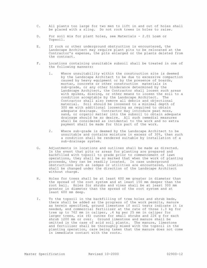
Master Specification Revised 10-2000 02900-12
C. All plants too large for two men to lift in and out of holes shall
be placed with a sling. Do not rock trees in holes to raise.
D. For soil mix for plant holes, see Materials - 2.01 Loam or Topsoil.
E. If rock or other underground obstruction is encountered, the
Landscape Architect may require plant pits to be relocated at the Contractor's expense, the pits enlarged or the plants deleted from the contract.
F. Locations containing unsuitable subsoil shall be treated in one of
the following manners:
1. Where unsuitability within the construction site is deemed by the Landscape Architect to be due to excessive compaction caused by heavy equipment or by the presence of boards, mortar, concrete or other construction materials in sub-grade, or any other hinderance determined by the Landscape Architect, the Contractor shall loosen such areas with spikes, discing, or other means to loosen the soil to a condition acceptable by the Landscape Architect. The Contractor shall also remove all debris and objectional material. Soil should be loosened to a minimal depth of 300 mm with additional loosening as required to obtain adequate drainage. Contractor may introduce peat moss, sand, or organic matter into the subsoil to obtain adequate drainage should he so desire. All such remedial measures shall be considered as incidental to the work and no extra payment shall be made for this part of the work.
2. Where sub-grade is deemed by the Landscape Architect to be
unsuitable and contains moisture in excess of 30%, then such
a condition shall be rendered suitable by installation of a sub-drainage system.
G. Adjustments in locations and outlines shall be made as directed.
In the event that pits or areas for planting are prepared and backfilled with topsoil to grade prior to commencement of lawn operations, they shall be so marked that when the work of planting proceeds, they can be readily located. In case underground obstructions such as ledges or utilities are encountered, location shall be changed under the direction of the Landscape Architect without charge.
H. Holes for trees shall be at least 600 mm greater in diameter than
the spread of the root system and at least 150 mm deeper than the root ball. Holes for shrubs and vines shall be at least 300 mm greater in diameter than the spread of the root system and at
least 600 mm deep.
I. To the topsoil in the backfilling of tree holes and shrub beds, there shall be added as the progress of the work permits, manure
as herein specified, ground limestone if soil tests indicate it is
needed, and commercial fertilizer at the rate of three 1.3 kg for tree up to 762 mm in caliper, .4 kg per 25 mm in caliper for larger trees, six (6) ounces for small shrubs and 226 g for each
shrub 1200 mm or over. Ground limestone and manure shall be omitted in the case of acid soil plants. The manure, limestone and fertilizer shall be thoroughly mixed with the topsoil in the
planting operation, care being taken that the manure does not come in immediate contact with the roots.

Master Specification Revised 10-2000 02900-13
J. The plants shall be planted in the center of the holes and at the
same depth as they previously grew. Loam shall be backfilled in layers of not more than 200 mm and each layer watered sufficiently to settle before the next layer is put in place. Loam shall be
tamped under edges of balled plants . Enough topsoil shall be used to bring the surfaces to finish grade when settled.
1. A saucer shall be provided around each plant as shown on the
drawings.
2. Plants shall be soaked with water twice within the first twenty-four (24) hours of time of planting. Water shall be applied with low pressure so as to soak in thoroughly
without dislodging the topsoil.
3. Approved weed mat shall be placed under all areas to be covered with mulch. Secure weed mat in place with a soil anchor, then cover with mulch as directed.
4. A 762 mm layer (after settlement) of mulch or approved equal
shall be applied directly on top of weed mat to the entire area of each saucer or planting bed.
3.04 PLANT BED EXCAVATIONS
Excavate tree pits and plant beds to the depth indicated on the detail sheet.
3.05 MAINTENANCE DURING CONSTRUCTION
A. Maintenance shall begin immediately after planting. Plants shall
be watered, mulched, weeded, pruned, sprayed, fertilized, cultivated, and otherwise maintained and protected until provisional acceptance. Settled plants shall be reset to proper
grade and position, planting saucer restored and dead material removed. Stakes and wires shall be tightened and repaired.
Defective work shall be corrected as soon as possible after it
becomes apparent and weather and season permit.
B. If a substantial number of plants are sickly or dead at the time of inspection, acceptance shall not be granted and the Contractor's responsibility for maintenance of all plants shall be
extended until replacements are made.
C. All replacements shall be plants of the same kind and size specified on the Plant List. They shall be furnished and planted
as specified above. The cost shall be borne by the Contractor. Replacements resulting from removal, loss, or damage due to occupancy of the project in any part, vandalism, physical damage
by animals, vehicles, etc., and losses due to curtailment of water by local authorities shall be approved and paid for by the Owner.
D. Plants shall be guaranteed for a period of one (1) year after
inspection and provisional acceptance.
E. At the end of the Establishment Period, inspection shall be made
again. Any plant required under this contract that is dead or unsatisfactory to the Owner shall be removed from the site. These shall be replaced during the normal planting season.
3.06 SEEDING
A. Area - All exterior ground within the limit of contract, except
surfaces occupied by buildings and structures and paving, except

Master Specification Revised 10-2000 02900-14
areas indicated to be undisturbed, shall be seeded or planted as
shown on drawings.
Furnish topsoil, finish grading, prepare seed bed, seed and maintain areas as indicated on the drawings.
B. Seed Bed Preparation - Grade areas to finish grades, filling as
needed or removing surplus dirt and floating areas to a smooth, uniform grade as indicated on grading plans. All lawn areas shall slope to drain. Where no grades are shown, areas shall have a
smooth and continual grade between existing or fixed controls (such as walks, curbs, catch basin, elevational steps or building) and elevations shown on plans. Roll, scarify, rake and level as
necessary to obtain true, even lawn surfaces. All finish grades shall meet approval of the Landscape Architect, before grass seed is sown. Loosen soil to a depth of 150 mm in lawn areas by
approved method of scarification and grade to remove ridges and depressions. Remove stones or foreign matter over 60 mm in
diameter from the top 60 mm of soil. Float lawn areas to
approximately finish grades.
C. Seed beds should be permitted to settle or should be firmed by rolling before seedings are made.
D. Seeding shall not be performed in windy weather.
E. Seeding shall be done in two (2) directions at right angles to
each other.
F. Lawn areas shall be seeded by sowing evenly with an approved
mechanical seeder at the rate of a minimum of 1.36 kg per 92.9 m2.
Culti-packer or approved similar equipment may be used to cover the seed and to form the seed bed in one operation. In areas
inaccessible to culti-packer, the seeded ground shall be lightly raked with flexible rakes and rolled with a water ballast roller. After rolling, seeded areas are to be lightly mulched with wheat
straw.
G. If the project completion date prohibits in-season planting, the Contractor shall prepare himself for out-of-season seeding or sodding so that all lawns shall be completed and ready for
acceptance at time of project completion, without additional cost to the Owner. Lawn maintenance shall be the same as for other planting.
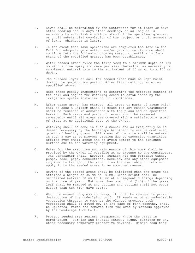
Master Specification Revised 10-2000 02900-15
H. Lawns shall be maintained by the Contractor for at least 30 days
after sodding and 60 days after seeding, or as long as is necessary to establish a uniform stand of the specified grasses,
or until substantial completion of the project or until acceptance of lawns, whichever is later.
I. In the event that lawn operations are completed too late in the
Fall for adequate germination and/or growth, maintenance shall continue into the following growing season or until a uniform stand of the specified grasses has been established.
J. Water seeded areas twice the first week to a minimum depth of 150
mm with a fine spray and once per week thereafter as necessary to supplement natural rain to the equivalent of 30 mm or to a 150 mm depth.
K. The surface layer of soil for seeded areas must be kept moist
during the germination period. After first cutting, water as specified above.
L. Make three weekly inspections to determine the moisture content of
the soil and adjust the watering schedule established by the
irrigation system installer to fit conditions.
M. After grass growth has started, all areas or parts of areas which fail to show a uniform stand of grass for any reason whatsoever
shall be reseeded in accordance with the plans and as specified herein. Such areas and parts of areas shall be reseeded repeatedly until all areas are covered with a satisfactory growth
of grass at no additional cost to the Owner.
N. Watering shall be done in such a manner and as frequently as is deemed necessary by the Landscape Architect to assure continued growth of healthy grass. All areas of the site shall be watered
in such a way as to prevent erosion due to excessive quantities
applied over small areas and to avoid damage to the finished surface due to the watering equipment.
O. Water for the execution and maintenance of this work shall be
provided by the Owner if possible at no expense to the Contractor. The Contractor shall, however, furnish his own portable tanks,
pumps, hose, pipe, connections, nozzles, and any other equipment
required to transport the water from the available outlets and apply it to the seeded areas in an approved manner.
P. Mowing of the seeded areas shall be initiated when the grass has
attained a height of 35 mm to 60 mm. Grass height shall be
maintained between 30 mm to 45 mm at subsequent cuttings depending on the time of year. Not more than one third (1/3) of the grass leaf shall be removed at any cutting and cutting shall not occur
closer than ten (10) days apart.
Q. When the amount of grass is heavy, it shall be removed to prevent destruction of the underlying turf. If weeds or other undesirable
vegetation threaten to smother the planted species, such vegetation shall be mowed or, in the case of rank growths, shall be uprooted, raked and removed from the area by methods approved
by the Landscape Architect.
R. Protect seeded area against trespassing while the grass is germinating. Furnish and install fences, signs, barriers or any other necessary temporary protective devices. Damage resulting

Master Specification Revised 10-2000 02900-16
from trespass, erosion, washout, settlement or other causes shall
be repaired by the Contractor at his expense.
S. Remove all fences, signs, barriers or other temporary protective devices after final acceptance.
3.07 SOD - SEE SODDING SPECIFICATION
A. Area - As noted on plan, a 1,000 mm wide strip shall be sodded
along walks, roadways, swales and parking areas to prevent washing
and erosion.
B. Sod Bed Preparation - Grade areas to finish grade, filling as
needed or removing surplus dirt, stones, debris, etc. and floating areas to a smooth, uniform grade as indicated on grading plans. All lawn areas are to slope to drain.
C. Sod shall be cut and laid on site the same day. Only healthy vigorous growing sod is to be laid.
D. Always lay sod across slope and tightly together so as to make a
solid area.
E. Roll or firmly but lightly tamp with suitable wooden or metal
tamper all new sod sufficiently to set or press sod into underlaying soil.
F. After sodding has been completed, clean up and thoroughly moisten
newly sodded areas. PART 4 MAINTENANCE CONTRACT
4.01 GENERAL LANDSCAPING
A. Contractor shall provide the Owner with three (3) written
proposals due no later that the established possession date for landscape maintenance from experienced local maintenance gardener certified by Landscape Ontario and capable of performing the work
outlined herein. The accepted proposal and maintenance contract will be for a period of 1 year and renewable in one year increments as per Owner's discretion. Maintenance will begin
immediately after final approval and acceptance of the landscaping by the Owner.
B. Landscape maintenance shall include all necessary watering,
cultivation, weeding, pruning, wound dressing, disease and insect
pest control, protective spraying, replacement of dead plant material (labour only), straightening plants which lean or sag, adjustments of plants which settle or are planted too low, mowing
of turf areas, replacement of mulch that has been displaced by
erosion or other means, repairing and reshaping of water rings or saucers, re-placement of mulch that has been displaced by erosion
or subsidence, and the reseeding or replanting of those areas affected. Removal of all rubbish, waste, tools, and equipment used in the execution of the contract at the end of each work day, and
any other procedure consistent with good horticultural practice necessary to insure normal, vigorous and healthy growth of all plant material are also part of this maintenance contract.
C. During the first year of the maintenance contract, any replacement
of plant material shall be the responsibility of the general

Master Specification Revised 10-2000 02900-17
landscape contractor with exceptions as listed in Section 2900, 3.05, C.
D. Landscape maintenance contractor shall purchase and maintain
Contractor's general liability insurance in the amounts determined
by the Owner to protect him from the Contractor's operations under the maintenance contract. Certification of such insurance shall be filed with the Owner prior to the commencement of the work.
4.02 WATERING
A. The quantity of water applied at one time shall be sufficient to
penetrate the soil to a minimum of 200 mm in shrub beds and 150 mm
in turf areas at a rate which will prevent saturation of the soil.
B. On-site water shall be furnished by the Owner. Hose and other watering equipment shall be furnished by the Landscape Contractor.
4.03 WEEDING
Maintenance contractor shall keep all planting areas free from weeds and
undesirable grasses by a method and by materials approved by the C.N.T.A.
4.04 DISEASE AND INSECT PEST CONTROL
Inspect all plant material at least once a month to locate any disease or insect pest infestations. Upon the discovery of any disease or
insect pest infestation, identify, or have identified, the nature or species of the infestation. A method of control in accordance with common Provincial standards shall be immediately implemented.
4.05 FERTILIZING
Maintenance contractor is to fertilize plant material on a regularly
scheduled program to fit the requirements of the plant material to
maintain vigorous and healthy plant growth. 4.06 PRUNING AND REPAIR
The amount of pruning shall be limited to the minimum necessary to remove dead or injured twigs and branches and to compensate for the loss of roots as a result of transplanting operation and/or to maintain safety in vehicular use areas. Pruning shall be done in such a manner as to not change the natural habit or shape of the plant. All cuts shall be made flush, leaving no stubs.
4.07 MOWING
Mow all grass areas at regular intervals to keep the grass height from
exceeding 76 mm. Mow grass areas in such a manner as to prevent clippings from blowing on paved areas, and sidewalks. Cleanup after mowing shall include sweeping or blowing of paved areas and sidewalks to
clear them from mowing debris. 4.08 CLEAN UP
During the course of maintenance planting, excess and waste materials shall be continuously and promptly removed at the end of each work day.
4.09 MAINTENANCE REPORT AND SCHEDULE OF ACTIVITIES
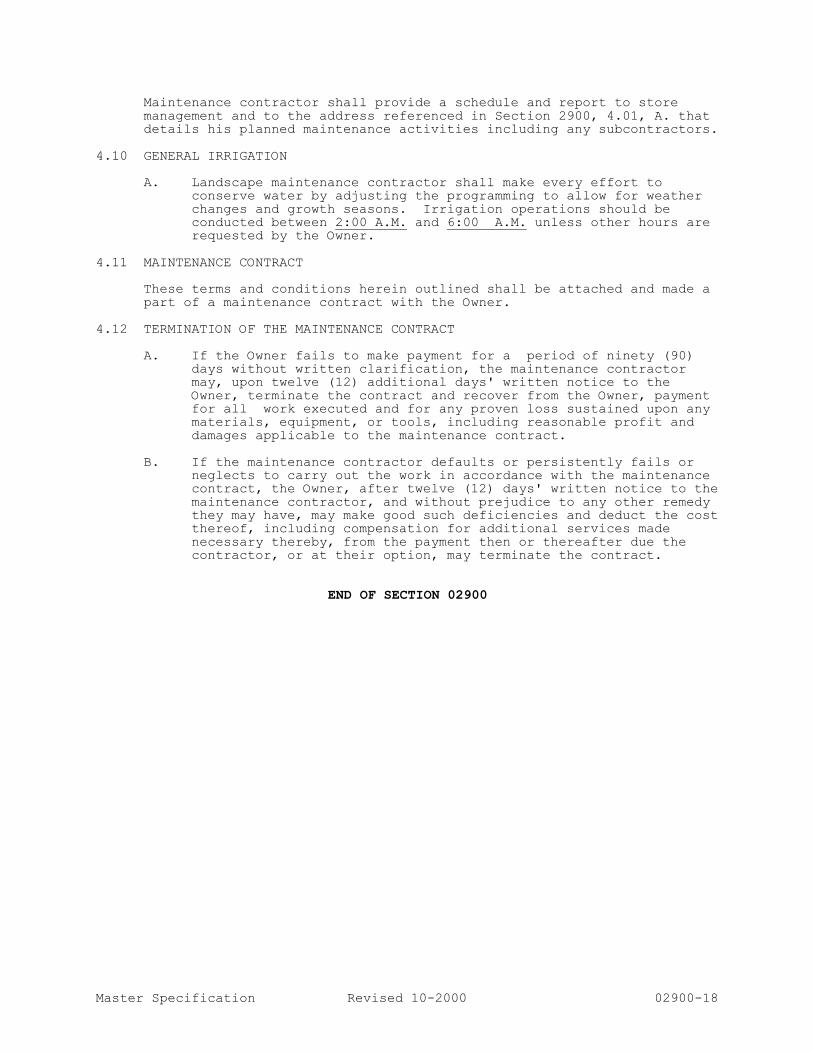
Master Specification Revised 10-2000 02900-18
Maintenance contractor shall provide a schedule and report to store
management and to the address referenced in Section 2900, 4.01, A. that details his planned maintenance activities including any subcontractors.
4.10 GENERAL IRRIGATION
A. Landscape maintenance contractor shall make every effort to
conserve water by adjusting the programming to allow for weather
changes and growth seasons. Irrigation operations should be conducted between 2:00 A.M. and 6:00 A.M. unless other hours are requested by the Owner.
4.11 MAINTENANCE CONTRACT
These terms and conditions herein outlined shall be attached and made a
part of a maintenance contract with the Owner. 4.12 TERMINATION OF THE MAINTENANCE CONTRACT
A. If the Owner fails to make payment for a period of ninety (90)
days without written clarification, the maintenance contractor may, upon twelve (12) additional days' written notice to the
Owner, terminate the contract and recover from the Owner, payment for all work executed and for any proven loss sustained upon any materials, equipment, or tools, including reasonable profit and
damages applicable to the maintenance contract.
B. If the maintenance contractor defaults or persistently fails or neglects to carry out the work in accordance with the maintenance contract, the Owner, after twelve (12) days' written notice to the
maintenance contractor, and without prejudice to any other remedy they may have, may make good such deficiencies and deduct the cost thereof, including compensation for additional services made
necessary thereby, from the payment then or thereafter due the contractor, or at their option, may terminate the contract.
END OF SECTION 02900

OPS Collision Reporting Centre TOPSOIL AND FINISH Section 02911
GRADING Page 1 of 2
PART 1 - GENERAL
1.1 Related Work .1 Planting of Trees, Shrubs and Groundcovers Section 02906
.2 Sodding Section 02933
1.2 Scope .1 This section specifies requirements for the supply and placing of
imported topsoil and the preparation of planting soil.
1.3 Source Quality Control .1 Acceptance of topsoil shall be subject to inspection and soil analysis
test results. Do not commence work until topsoil accepted by
Consultant.
.2 Inspection and testing of topsoil will be carried out by an
independent testing laboratory. Cost for tests shall be included in
the lump sum amount.
1.4 Testing .1 Test topsoil from source for clay, sand and silt, NPK, Mg, soluble
salt content, pH value, growth inhibitors, soil sterilant, organic
matter, and conductivity.
.2 Use 25 mm diameter sampling tube or spade and take 25 samples
per hectare to full depth of topsoil at random across entire area to be stripped or 1 sample per 100 m
3 of stockpiled topsoil. Mix
samples together thoroughly before submitting for testing.
.3 Submit 0.5 kg sample of topsoil to testing laboratory and indicate
present use, intended use, type of subsoil, and quality of drainage.
Prepare and ship sample in accordance with provincial regulations
and testing laboratory requirements.
.4 Determine required treatment to bring pH value of soil between
range of 5.5 to 7.5 level.
.5 Submit 1 copy of soil analysis and recommendation for corrections,
to Consultant
.6 Test laboratory to be to Consultant's approval.
1.5 Scheduling of Work .1 Schedule placing of topsoil and grading to permit seeding within 7
days.
1.6 Definition .1 Friable: Soil, which is easily crumbled through fingers when, held by
hand.
PART 2 - PRODUCTS
2.1 Materials .1 Topsoil:
.1 Friable, neither heavy clay nor of very light sandy nature consisting
of 70% sand, 10% silt, 20% clay and pH value of 5.5 to 7.5.
.2 Organic Matter, 4% for clay loams, and 2% for sandy loams to
maximum of 20% by volume.
.2 Peat moss:
.1 Derived from partially decomposed fibrous or cellular stems and
leaves of species of Sphagnum Mosses.
.2 Elastic and homogeneous, brown in colour.
.3 Free of wood and deleterious material which could prohibit growth.
.4 Shredded particle minimum size: 5 mm.
.3 Fertilizer:
.1 Shall be subject to the results of the soil analysis test of supplied
topsoil.
.4 Bonemeal:
.1 Raw commercial bonemeal, finely ground with a minimum analysis
of 20% phosphoric acid.

OPS Collision Reporting Centre TOPSOIL AND FINISH Section 02911
GRADING Page 2 of 2
.2 Gradation requirements: percentage passing by weight, 90% passing 1.0 mm sieve, 50% passing 0.125 mm sieve.
.5 Limestone: .1 Ground agricultural limestone containing minimum 85% of total
carbonates. .2 Gradation requirements: percentage passing by weight, 90%
passing 1.0 mm sieve, 50% passing 0.125 mm sieve. .6 Planting Mixture:
.1 Mix 4 parts topsoil with 1 part peatmoss. Incorporate bone meal into planting soil at a rate of 0.5kg/m3 of soil mixture.
PART 3 - EXECUTION
3.1 Preparation of Existing Grade
.1 Grade soil, eliminating uneven areas and low spots, ensuring positive drainage. Remove soil contaminated with toxic materials. Dispose of removed materials as directed by Consultant.
.2 Cultivate entire area, to receive topsoil, to depth of 100 mm. Repeat cultivation in those areas where equipment used for hauling and spreading has compacted soil.
.3 Remove surface debris, roots, vegetation, branches, stones and other deleterious materials in excess of 50 mm diameter.
3.2 Spreading of Topsoil .1 Spread topsoil after Consultant has inspected and approved subgrade.
.2 Spread topsoil with adequate moisture in uniform layers over approved, unfrozen subgrade, where seeding is indicated.
.3 Place topsoil to following minimum depths:
125mm for sodded areas.
3.3 Soil Amendments .1 Apply soil amendments at rate as specified and as determined from
soil sample test. .2 Mix soil amendment well into full depth of topsoil prior to application
of fertilizer.
3.4 Application of Fertilizer .1 Spread fertilizer uniformly over entire area of topsoil at manufacturer's recommended rate determined on basis of soil sample test.
.2 Mix fertilizer thoroughly to full depth of topsoil.
3.5 Finish Grading .1 Fine grade and loosen topsoil prior to seeding. Eliminate rough spots and low areas to ensure positive drainage. Prepare loose friable bed by means of cultivation and subsequent raking.
.2 Roll to consolidate topsoil for areas to be sodded, leaving surface smooth, uniform, firm against deep foot printing, and with fine loose texture, to approval of Consultant.
END OF SECTION
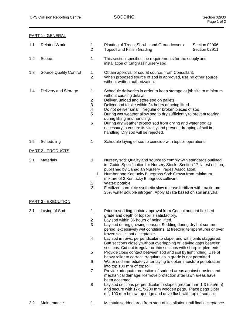
OPS Collision Reporting Centre SODDING Section 02933
Page 1 of 2
PART 1 - GENERAL
1.1 Related Work .1 Planting of Trees, Shrubs and Groundcovers Section 02906
.2 Topsoil and Finish Grading Section 02911
1.2 Scope .1 This section specifies the requirements for the supply and installation of turfgrass nursery sod.
1.3 Source Quality Control .1 Obtain approval of sod at source, from Consultant.
.2 When proposed source of sod is approved, use no other source without written authorization.
1.4 Delivery and Storage .1
.2
Schedule deliveries in order to keep storage at job site to minimum without causing delays. Deliver, unload and store sod on pallets.
.3 Deliver sod to site within 24 hours of being lifted.
.4 Do not deliver small, irregular or broken pieces of sod.
.5
.6
During wet weather allow sod to dry sufficiently to prevent tearing during lifting and handling. During dry weather protect sod from drying and water sod as
necessary to ensure its vitality and prevent dropping of soil in handling. Dry sod will be rejected.
1.5 Scheduling .1 Schedule laying of sod to coincide with topsoil operations.
PART 2 - PRODUCTS
2.1 Materials .1 Nursery sod: Quality and source to comply with standards outlined
in `Guide Specification for Nursery Stock,' Section 17, latest edition,
published by Canadian Nursery Trades Association.
.1 Number one Kentucky Bluegrass Sod: Grown from minimum
mixture of 3 Kentucky Bluegrass cultivars
.2 Water: potable.
.3 Fertilizer: complete synthetic slow release fertilizer with maximum
35% water soluble nitrogen. Apply at rate based on soil analysis.
PART 3 - EXECUTION
3.1 Laying of Sod .1 Prior to sodding, obtain approval from Consultant that finished
grade and depth of topsoil is satisfactory.
.2 Lay sod within 36 hours of being lifted.
.3 Lay sod during growing season. Sodding during dry hot summer
period, excessively wet conditions, at freezing temperatures or over
frozen soil, is not acceptable.
.4 Lay sod in rows, perpendicular to slope, and with joints staggered.
Butt sections closely without overlapping or leaving gaps between
sections. Cut out irregular or thin sections with sharp implements.
.5 Provide close contact between sod and soil by light rolling. Use of
heavy roller to correct irregularities in grade is not permitted.
.6 Water sod immediately after laying to obtain moisture penetration
into top 100 mm of topsoil.
.7 Provide adequate protection of sodded areas against erosion and
mechanical damage. Remove protection after lawn areas have
been accepted.
.8 Lay sod sections perpendicular to slopes greater than 1:3 (rise/run)
and secure with 17x17x200 mm wooden pegs. Place pegs 3 per m
2, 100 mm below top edge and drive flush with top of sod soil.
3.2 Maintenance .1 Maintain sodded area from start of installation until final acceptance.
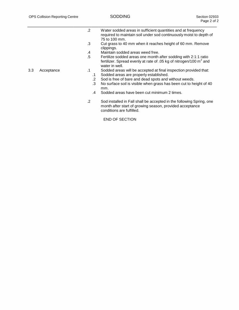
OPS Collision Reporting Centre SODDING Section 02933
Page 2 of 2
.2
.3
Water sodded areas in sufficient quantities and at frequency required to maintain soil under sod continuously moist to depth of 75 to 100 mm. Cut grass to 40 mm when it reaches height of 60 mm. Remove
clippings. .4 Maintain sodded areas weed free. .5 Fertilize sodded areas one month after sodding with 2:1:1 ratio
fertilizer. Spread evenly at rate of .05 kg of nitrogen/100 m2
and
water in well. 3.3 Acceptance .1 Sodded areas will be accepted at final inspection provided that:
.1 Sodded areas are properly established.
.2 Sod is free of bare and dead spots and without weeds.
.3 No surface soil is visible when grass has been cut to height of 40
mm.
.4 Sodded areas have been cut minimum 2 times.
.2 Sod installed in Fall shall be accepted in the following Spring, one
month after start of growing season, provided acceptance
conditions are fulfilled.
END OF SECTION

INDEX SITE WORKS DIVISION-2 SPECIFICATIONS PROJECT NO. 163600889
OPS 211 HUNTMAR ROAD
SECTION 02035 CONTRACTORS INFORMATION REQUEST
SECTION 02100 SITE PREPARATION
SECTION 02200 EARTHWORK
SECTION 02222 EXCAVATION, BACKFILLING AND COMPACTING FOR UTILITIES
SECTION 02223 EXCAVATION, BACKFILLING AND COMPACTING FOR PAVEMENT
SECTION 02227 AGGREGATE MATERIALS
SECTION 02260 TOPSOIL AND FINISH GRADING
SECTION 02505 GRANULAR BASE COURSE
SECTION 02511 ASPHALTIC CONCRETE PAVING
SECTION 02525 CURB AND SIDEWALKS
SECTION 02584 PAVEMENT MARKINGS
SECTION 02687 SITE GAS LINES
SECTION 02846 SIGNAGE
SECTION 02900 LANDSCAPING
SECTION 02906 PLANTING OF TREES, SHRUBS AND GROUND COVERS
SECTION 02911 TOPSOIL AND FINISH GRADING
SECTION 02933 SODDING
END OF SECTION INDEX
Page 1 of 1

SECTION 02035 CONTRACTOR'S INFORMATION REQUEST
PART I GENERAL
All work shall conform to the local Municipal Specifications where conflicts exist. Applicable CSA standards will prevail where ANSI or ASTM conflict with CSA standards.
1.01 SUMMARY
A. Section Includes:
1. 1. Administrative and procedural requirements for handling and
processing "Contractor's Information Request" (CIR).
2. 2. "Contractor's Information Request" process diagram is attached at the
end of this Section.
3. 3. "Contractor's Information Request" form is attached at the end of this
Section.
1.02 DEFINITION
A. Requests for Information: A formal process used during the
construction phase to facilitate communication between the contractor
and the Civil Engineering Consultant (CEC) with regard to requests
for additional information and clarification of the intent of the
Contract Documents (Drawings and Specifications).
B. Do not use "Contractor's Information Request" form during bidding.
Direct questions during bidding phase as indicated in the bid
documents.
1.03 PROCEDURE
A. Conditions Requiring Clarification of the Contract Documents:
1. 1. Contractor shall submit a "Contractor's Information Request"to the
Civil Engineering Consultant.
2. 2. Submit "Contractor's Information Request" from Contractor's office
or field office only. "Requests for Information"submitted directly from
subcontractors or suppliers will not be accepted.
3. 3. Generate "Requests for Information" by one source per project and
number accordingly.
4. 4. Submit one "Contractor's Information Request" per form.
Master Specification Revised 10-2000 02035-
1
B. Civil Engineering Consultant will review CIR from the Contractorwith
reasonable promptness and the Contractor will be notified in writing
of decisions made.
1. The Civil Engineering Consultant's written response to the CIR
shall not be considered as a Change Order or ChangeDirective,

nor does it authorize changes in the Contract Sum or Contract
Time.
C. Contractor shall maintain a log of "Requests for Information" sent
to, and responses from Civil Engineering Consultant. "Requests for
Information" log shall be sent, by Fax, every Friday to the Civil
Engineering Consultant.
D. All "Requests for Information" regarding scheduling, costing and
owner provided equipment coordination shall be directed to the Civil
Engineering Consultant.
1.04 REQUEST FOR INFORMATION FORM
A. Submit "Contractor's Information Request" on the attached
"Contractor's Information Request" form, or format accordingly on
letterhead. Civil Engineering Consultant will not respond to requests
for information unless this form or format is utilized.
B. Where submittal form or format does not provide space needed for
complete information, additional sheets may be attached.
END OF SECTION 02035
Master Specification Revised 10-2000

02035- 2
CONTRACTOR'S INFORMATION REQUEST
DATE: CIR NO:
TO: PROJECT: (City, Province)
FROM: (General Contractor)
(Project Superintendent)
Store # CPM Project #
SPECIFICATION
SECTION:
(Job Site Fax Number)
INFORMATION REQUESTED:
Requested by:
REPLY:
DWG. NO:
DETAIL
NO:

Master Specification Revised 10-2000 02035-3

02100 - 1 of 4
SECTION 02100 SITE PREPARATION PROJECT NO. 163600889
PART 1 GENERAL
A. General Conditions, Supplementary Conditions and Division 01 apply to this
Section.
1.01 SECTION INCLUDES:
A. Identification of the construction limits.
B. Cleaning site of debris, grass, trees and other plant life in preparation
for site or building excavation Work.
C. Protection of existing structures, trees or vegetation indicated on the
Contract Documents to remain.
D. Stripping topsoil from areas that are to be incorporated into the limits
of the Project and where so indicated on the Drawings.
1.02 RELATED SECTIONS
A. Section 02200 - Earthwork
1.03 ENVIRONMENTAL REQUIREMENTS
A. Construct temporary erosion control systems as shown on the plans or as
directed by the Sitework Engineer of Record to protect adjacent properties
and water resources from erosion and sedimentation.
B. Hickenbottom risers are to be constructed as detailed on the Drawings
including installation, maintenance and removal, storm sewers, clear stone
jacket, maintenance hole structures, and restoration of disturbed areas
including rip rap as detailed, grading, topsoil and sod, and all other
labour and/or materials required to complete the Work.
C. The Contractor shall not allow silt-laden water to enter any adjacent
sewer system, adjoining properties or existing watercourse. To this end,
the Contractor will be required to construct any channel Work and/or storm
sewer pond outfalls in the dry. The method of dewatering and siltation
control will be as specified in the Drawings.
D. Construction of the pond is to include all excavation and removal of
excavated material, maintenance during construction, sub-excavation of
saturated material and placement of „engineered backfill‟ to proposed pre-
grade elevations after service installation. Excavated materials are to
be stockpiled for use as pond backfill material placed as engineered fill
or disposed of offsite as directed by the Sitework Engineer of Record.
E. It shall be the responsibility of the Contractor to contain and control
storm water runoff prior to the main outfalls being operational.
F. In the event that the site Work on this Project will be under the
jurisdiction of a Municipal Topsoil Preservation by-law, Conservation
Authority or Ministry of Natural Resources Work permits, the Contractor is
responsible for ensuring compliance with the applicable regulations
throughout the entire construction period. The permits require erosion and

02100 - 2 of 4
SECTION 02100 SITE PREPARATION PROJECT NO. 163600889
sedimentation control measures to be in place during construction and
include monitoring of storm water flows during construction.
G. The Contractor shall be responsible for conducting the stormwater
management and site stabilization practices in accordance with the
governmental authorities requirements and for any enforcement action taken
or imposed by the governmental authorities, including the cost of fines,
construction delays and remedial actions resulting from the Contractors
failure to comply with all provisions of the requirements.
1.04 PROJECT CONDITIONS
A. Conditions existing at time of inspection for bidding purposes will be
maintained by Owner in so far as practical.
B. Variations to conditions or discrepancy in actual conditions as they apply
to site preparation operations are to be brought to the attention of the
Sitework Engineer of Record prior to the commencement of any site Work.
PART 2 PRODUCTS
A. Off-site materials shall be transported to Project using well maintained
and operating vehicles. Once on site, transporting vehicles shall stay on
designated haul roads and shall at no time endanger improvements by
rutting, overloading, or pumping.
PART 3 EXECUTION
3.01 PREPARATION
A. Verify that existing plant life and clearing limits are clearly tagged,
identified and marked in such a manner as to insure their safety
throughout construction operations.
3.02 PROTECTION
A. Locate and identify existing utilities that are to remain and protect them
from damage.
B. Any information shown for existing utilities has been provided by others.
The Contractor is responsible for locating and verifying any possible conflicts and/or discrepancies with regard to existing / proposed utilities and report such conflicts and/or discrepancies to the Sitework Engineer of Record within 48 hours prior to commencement of the Work. Lost time due to failure of the Contractor to confirm utility locations and notify the Sitework Engineer of Record of possible conflicts 48 hours prior to construction will be at the Contractor‟s expense.
C. The Contractor shall inform the Sitework Engineer of Record, the Local
Municipality, and the utility Owner or authority of the proposed method of
excavation around, and temporary support of utilities and services prior
to the start of construction. The proposed method will be subject to the
approval of the authority having jurisdiction.
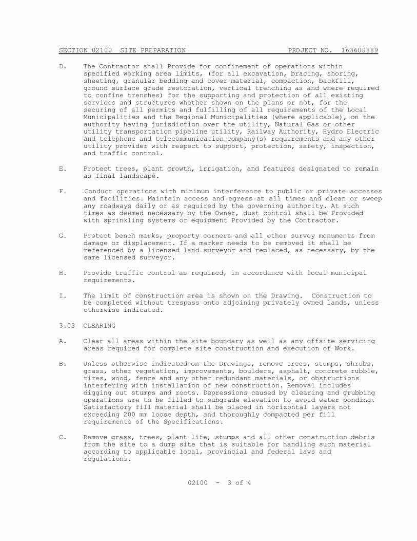
02100 - 3 of 4
SECTION 02100 SITE PREPARATION PROJECT NO. 163600889
D. The Contractor shall Provide for confinement of operations within
specified working area limits, (for all excavation, bracing, shoring,
sheeting, granular bedding and cover material, compaction, backfill,
ground surface grade restoration, vertical trenching as and where required
to confine trenches) for the supporting and protection of all existing
services and structures whether shown on the plans or not, for the
securing of all permits and fulfilling of all requirements of the Local
Municipalities and the Regional Municipalities (where applicable), on the
authority having jurisdiction over the utility, Natural Gas or other
utility transportation pipeline utility, Railway Authority, Hydro Electric
and telephone and telecommunication company(s) requirements and any other
utility provider with respect to support, protection, safety, inspection,
and traffic control.
E. Protect trees, plant growth, irrigation, and features designated to remain
as final landscape.
F. Conduct operations with minimum interference to public or private accesses
and facilities. Maintain access and egress at all times and clean or sweep
any roadways daily or as required by the governing authority. At such
times as deemed necessary by the Owner, dust control shall be Provided
with sprinkling systems or equipment Provided by the Contractor.
G. Protect bench marks, property corners and all other survey monuments from
damage or displacement. If a marker needs to be removed it shall be
referenced by a licensed land surveyor and replaced, as necessary, by the
same licensed surveyor.
H. Provide traffic control as required, in accordance with local municipal
requirements.
I. The limit of construction area is shown on the Drawing. Construction to
be completed without trespass onto adjoining privately owned lands, unless otherwise indicated.
3.03 CLEARING
A. Clear all areas within the site boundary as well as any offsite servicing
areas required for complete site construction and execution of Work.
B. Unless otherwise indicated on the Drawings, remove trees, stumps, shrubs,
grass, other vegetation, improvements, boulders, asphalt, concrete rubble,
tires, wood, fence and any other redundant materials, or obstructions
interfering with installation of new construction. Removal includes
digging out stumps and roots. Depressions caused by clearing and grubbing
operations are to be filled to subgrade elevation to avoid water ponding.
Satisfactory fill material shall be placed in horizontal layers not
exceeding 200 mm loose depth, and thoroughly compacted per fill
requirements of the Specifications.
C. Remove grass, trees, plant life, stumps and all other construction debris
from the site to a dump site that is suitable for handling such material
according to applicable local, provincial and federal laws and
regulations.

02100 - 4 of 4
SECTION 02100 SITE PREPARATION PROJECT NO. 163600889
3.04 TOPSOIL EXCAVATION
A. Strip topsoil from areas that are to be filled, excavated, landscaped or
re-graded to such a depth that it prevents intermingling with underlying
subsoil or questionable material.
B. Cut heavy growths of grass from areas before stripping and remove with the
rest of the cleared vegetative material.
C. Topsoil shall consist of organic surficial soil found in depth of not less
than 150 mm. Satisfactory topsoil is reasonably free of subsoil, clay
lumps, stones and other objects over 50 mm in diameter, weeds, roots, and
other objectionable material.
D. Stockpile topsoil in storage piles in areas shown or where directed.
Construct storage piles to freely drain surface water. Cover storage piles as required to prevent windblown dust. Dispose of unsuitable topsoil as specified for waste material. Excess topsoil shall be removed from the site by the Contractor unless specifically noted otherwise on the Drawings.
3.05 DUST CONTROL
A. The Contractor will be responsible for all dust control in accordance with
local municipal standards, bylaws and requirements including supply and
placement of water, calcium, or other means as directed by the Sitework
Engineer of Record.
END OF SECTION 02100
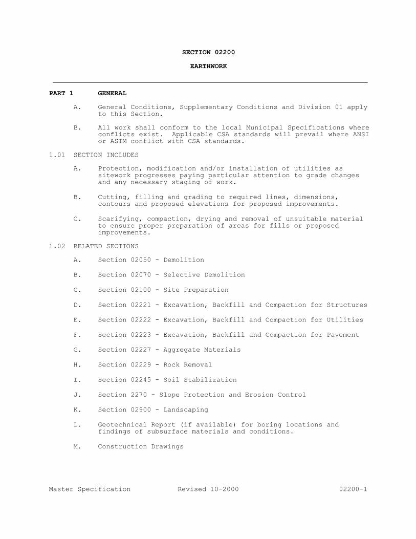
Master Specification Revised 10-2000 02200-1
SECTION 02200
EARTHWORK
PART 1 GENERAL
A. General Conditions, Supplementary Conditions and Division 01 apply
to this Section.
B. All work shall conform to the local Municipal Specifications where conflicts exist. Applicable CSA standards will prevail where ANSI or ASTM conflict with CSA standards.
1.01 SECTION INCLUDES
A. Protection, modification and/or installation of utilities as
sitework progresses paying particular attention to grade changes and any necessary staging of work.
B. Cutting, filling and grading to required lines, dimensions,
contours and proposed elevations for proposed improvements.
C. Scarifying, compaction, drying and removal of unsuitable material
to ensure proper preparation of areas for fills or proposed
improvements. 1.02 RELATED SECTIONS
A. Section 02050 - Demolition
B. Section 02070 – Selective Demolition
C. Section 02100 - Site Preparation
D. Section 02221 - Excavation, Backfill and Compaction for Structures
E. Section 02222 - Excavation, Backfill and Compaction for Utilities
F. Section 02223 - Excavation, Backfill and Compaction for Pavement
G. Section 02227 - Aggregate Materials
H. Section 02229 - Rock Removal
I. Section 02245 - Soil Stabilization
J. Section 2270 - Slope Protection and Erosion Control
K. Section 02900 - Landscaping
L. Geotechnical Report (if available) for boring locations and
findings of subsurface materials and conditions.
M. Construction Drawings
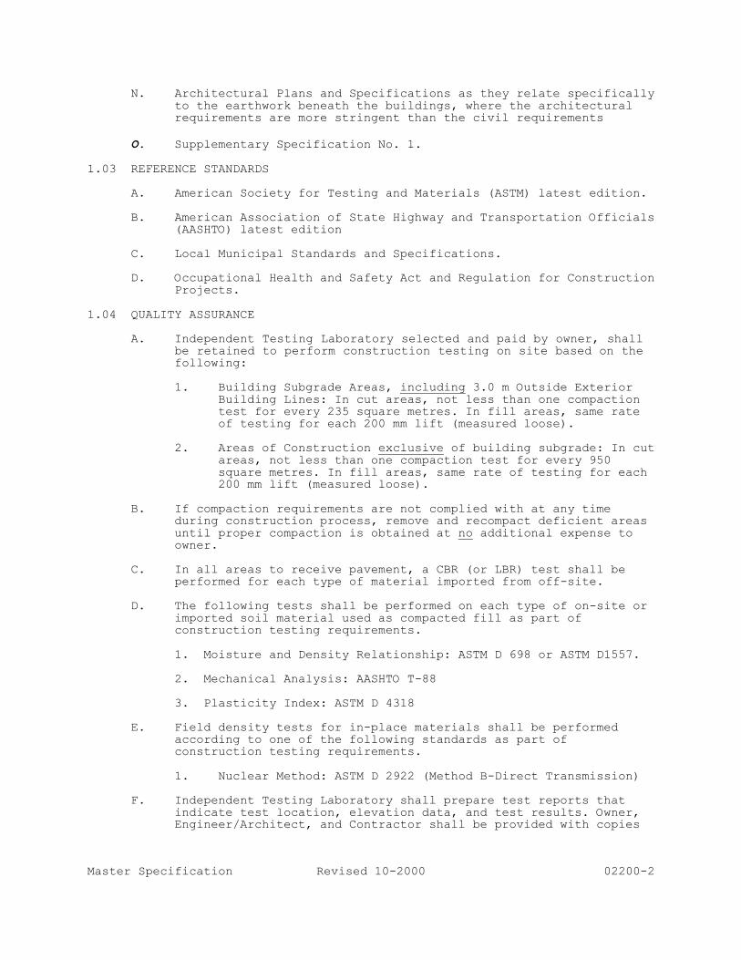
Master Specification Revised 10-2000 02200-2
N. Architectural Plans and Specifications as they relate specifically
to the earthwork beneath the buildings, where the architectural requirements are more stringent than the civil requirements
O. Supplementary Specification No. 1.
1.03 REFERENCE STANDARDS
A. American Society for Testing and Materials (ASTM) latest edition.
B. American Association of State Highway and Transportation Officials (AASHTO) latest edition
C. Local Municipal Standards and Specifications.
D. Occupational Health and Safety Act and Regulation for Construction
Projects. 1.04 QUALITY ASSURANCE
A. Independent Testing Laboratory selected and paid by owner, shall
be retained to perform construction testing on site based on the following:
1. Building Subgrade Areas, including 3.0 m Outside Exterior
Building Lines: In cut areas, not less than one compaction test for every 235 square metres. In fill areas, same rate of testing for each 200 mm lift (measured loose).
2. Areas of Construction exclusive of building subgrade: In cut
areas, not less than one compaction test for every 950
square metres. In fill areas, same rate of testing for each 200 mm lift (measured loose).
B. If compaction requirements are not complied with at any time
during construction process, remove and recompact deficient areas
until proper compaction is obtained at no additional expense to owner.
C. In all areas to receive pavement, a CBR (or LBR) test shall be
performed for each type of material imported from off-site.
D. The following tests shall be performed on each type of on-site or
imported soil material used as compacted fill as part of construction testing requirements.
1. Moisture and Density Relationship: ASTM D 698 or ASTM D1557.
2. Mechanical Analysis: AASHTO T-88
3. Plasticity Index: ASTM D 4318
E. Field density tests for in-place materials shall be performed
according to one of the following standards as part of construction testing requirements.
1. Nuclear Method: ASTM D 2922 (Method B-Direct Transmission)
F. Independent Testing Laboratory shall prepare test reports that
indicate test location, elevation data, and test results. Owner, Engineer/Architect, and Contractor shall be provided with copies
Master Specification Revised 10-2000 02200-3
of reports within 96 hours of time test was performed. In event
that any test performed fails to meet these Specifications, owner and contractor shall be notified immediately by independent testing laboratory.
G. All costs related to re-testing due to failures shall be paid for by the
contractor at no additional expense to owner. Owner reserves the right to employ an Independent Testing Laboratory and to direct
any testing that is deemed necessary. Contractor shall provide free access to site for testing activities.
1.05 SUBMITTALS
A. Submit a sample of each type of off-site fill materials that is to
be used at the site in an airtight, 5 kg container for the testing laboratory.
B. Submit the name of each material supplier and specific type and
source of each material. Any change in source throughout the job requires approval of the owner or engineer.
C. For use of fabrics or geogrids, a design shall be submitted for
approval by the Owner. PART 2 PRODUCTS
2.01 MATERIALS
A. Excavated and re-used material for subsoil fill as specified
herein.
B. Aggregate fill as specified in Section 02227.
C. Imported subsoil material approved by the owner and specified herein.
D. Topsoil fill as specified in Section 02100.
E. Acceptable stabilization fabrics and Geogrids or Equivalents as
approved by the Geotechnical Engineer as specified in contract documents.
F. Filter/Drainage Fabrics as specified in contract documents, or
equivalent as approved by the Geotechnical Engineer. 2.02 EQUIPMENT
Off-site materials shall be transported to project using well maintained
and operating vehicles. Once on site, transporting vehicles shall stay on designated haul roads and shall at no time endanger improvements by rutting, overloading, or pumping.

Master Specification Revised 10-2000 02200-4
PART 3 EXECUTION 3.01 PREPARATION
A. Identify required lines, levels, contours and datum
Survey stakes with exact elevations must be positioned to identify the engineered fill areas and the proposed finished fill grade.
B. Locate and identify existing utilities that are to remain and
protect them from damage.
C. Notify utility companies to remove and/or relocate any utilities that are in conflict with the proposed improvements.
D. Protect plant life, lawns, fences, existing structures, sidewalks,
paving and curbs from excavating equipment and vehicular traffic.
E. Protect benchmarks, property corners and all other survey
monuments from damage or displacement. If a marker needs to be removed it shall be referenced by a licensed land surveyor and
replaced, as necessary, by the same.
F. Remove from site material encountered in grading operations that, in opinion of owner or owners representative, is unsuitable or undesirable for backfilling, subgrade or foundation purposes and
all surplus fill materials. Dispose of in a manner satisfactory to owner. Backfill areas with layers of suitable material and compact as specified.
G. Prior to placing fill in low areas, such as previously existing
creeks, ponds, or lakes, perform following procedures. All work must be performed per applicable legislation/regulation and as approved by Engineer.
1. Drain water out by gravity with ditch having flow line
lower than lowest elevation in low area. If drainage cannot be performed by gravity ditch, use adequate pump to obtain same results.
2. After drainage of low area is complete, remove mulch, mud,
debris, and other unsuitable material by using acceptable equipment and methods that will keep natural soils
underlying low areas dry and undisturbed.
3. If proposed for fill, all muck, mud, and other materials removed from above low areas shall be dried on-site by spreading in thin layers for observation by owner or owners
representative. Material shall be inspected and, if found to be suitable for use as fill material, shall be incorporated into lowest elevation of site filling
operation, but not under the building area or within 3.0 m
of perimeter of building pad or paving subgrade. If, after observation by owner or owners representative, material is
found to be unsuitable, all unsuitable material shall be removed from site.
4. In the event of a site material deficit, co-ordinate, and
import fill from off site and include all costs as specified
herein.

Master Specification Revised 10-2000 02200-5
The fill is not to be brought to the site until such time that a sample has been reviewed and tested by qualified engineers, with respect to suitability of material for
filling purposes intended, and it is certified that the material is free of chemical or toxic contaminants.
3.02 EXCAVATION FOR FILLING AND GRADING
A. Classification of Excavation: Contractor by submitting bid
acknowledges that he has investigated the site to determine type,
quantity, quality, and character of excavation work to be performed. All excavation to comply with requirements of the OHSA for construction projects.
B. Perform excavation using capable well maintained equipment and
methods acceptable to owner and governing agencies.
C. When performing grading operations during periods of wet weather, provide adequate drainage and ground water management to control
moisture of soils.
D. Shore, brace, and drain excavations as necessary to maintain safe, secure, and free of water at all times.
E. Excavated material containing rock or stone greater than 150 mm in
largest dimension is unacceptable as fill within the proposed
building and paving area.
F. Rock or stone less than 150 mm in largest dimension is acceptable as fill up to 600 mm below the surface of proposed subgrade when mixed with suitable material.
G. Rock or stone less than 50 mm in largest dimension and mixed with
suitable material is acceptable as fill within the upper 600 mm of proposed subgrade.
3.03 FILLING AND SUBGRADE PREPARATION
A. Fill areas to contours and elevations shown with unfrozen
materials.
B. Place fill in continuous lifts specified herein.
C. Refer to Section 02221 for filling requirements for structures.
D. Refer to Section 02222 for filling requirements for utilities.
E. Refer to Section 02223 for filling requirements for pavements.
F. Areas exposed by excavation or stripping and on which subgrade
preparations are to be performed shall be scarified to minimum depth of 200 mm and compacted to minimum of 98% SPMDD, unless
otherwise specified in the contract documents or drawings at a moisture content of not less than 1% below and not more than 3% above, or as directed by the Geotechnical Engineer, the optimum
moisture content. These areas shall then be proofrolled to detect any areas of insufficient compaction. Proofrolling shall be accomplished by making a minimum of two (2) complete passes with a
fully-loaded tandem-axle dump truck, or approved equivalent, in each of the two perpendicular directions under the supervision and
Master Specification Revised 10-2000 02200-6
direction of a field geotechnical engineer. Areas of failure shall
be excavated and re-compacted as stated above.
G. Fill materials used in preparation of subgrade shall be placed in lifts or layers not to exceed 200 mm loose measure and compacted
to a minimum density of 98% SPMDD unless otherwise specified in the contract documents or drawings at a moisture content of not less than 1% below and not more than 3% above the optimum moisture
content or as directed by the Geotechnical Engineer.
H. Material imported from off-site shall have a CBR (California Bearing Ratio) or LBR (Limerock Bearing Ratio) value equal to or above the pavement design subgrade CBR or LBR value indicated on
the Drawings, and subject to acceptance by the Engineer. 3.04 MAINTENANCE OF SUBGRADE
A. Finished subgrades shall be verified to ensure proper elevation
and conditions for construction above subgrade.
B. Protect subgrade from excessive wheel loading during construction, including concrete trucks and dump trucks.
C. Remove areas of finished subgrade found to have insufficient
compaction density to depth necessary and replace in a manner that will comply with compaction requirements by use of material equal to or better than best subgrade material on site. Surface of
subgrade after compaction shall be hard, uniform, smooth, stable, and true to grade and cross-section.
3.05 FILTER FABRIC
A. The filter material shall be as described in the appropriate
Appendices and/or Drawings or an equal alternative and the
Contractor is required to have a sample of the material delivered to the site for approval prior to commencing the installation.
Place filter material in the manner outlined by the manufacturer or as specified. Adjacent sections of filter cloth shall be
overlapped a minimum of 600 mm unless otherwise noted. 3.06 RIP-RAP
A. Place rip-rap in all areas where indicated on the Drawings. The
stone for rip-rap shall consist of fieldstone or rough unhewn quarry stone as nearly uniform, in section as is practical. The
stones shall be dense, resistant to the action of air and water, and suitable in all aspects for the purpose intended
B. Slopes and other areas to be protected shall be dressed to the
line and grade shown on the plans prior to the placing of rip-rap. Contractor shall undercut the areas to receive rip-rap to an
elevation equal to the final elevation less the average diameter of the stones before placing the rip-rap.
C. Filter fabric and bedding stone shall be installed prior to the
placement of the stones if so indicated on the drawings. The bedding stone shall be quarried and crushed angular limestone, or approved equivalent, in accordance with Section 02227 and shall be
Master Specification Revised 10-2000 02200-7
150 mm in depth. Filter fabric shall be as specified herein and
as detailed on the plans.
D. Stones shall be placed so that the greater portion of their weight is carried by the earth and not by the adjacent stones. The stones
shall be placed in a single layer with close joints. The upright areas of the stone shall make an angle of approximately 90-degree with the embankment slope. The courses shall be placed from the
bottom of the embankment upward, the larger stones being placed in the lower courses. Open joints shall be filled with spalls. Stones shall be embedded in the embankment as necessary to present a
uniform top surface such that the variation between tops of adjacent stones shall not exceed 75 mm.
3.07 FINISH GRADING
A. Grade all areas where finish grade elevations or contours are
indicated on Drawings, other than paved areas and buildings,
including excavated areas, filled and transition areas, and
landscaped areas. Graded areas shall be uniform and smooth, free from rock, debris, or irregular surface changes. Finished subgrade surface shall not be more than 30 mm above or below established
finished subgrade elevation, and all ground surfaces shall vary uniformly between indicated elevations. Finish ditches shall be graded to allow for proper drainage without ponding and in a
manner that will minimize erosion potential. For topsoil application, refer to Section 02900 Landscaping.
B. Correct all settlement and eroded areas within one year after date
of completion at no additional expense to owner. Bring grades to proper elevation. Replant or replace any grass, shrubs, bushes, or other vegetation that appears dead, dying or disturbed by
construction activities. Refer to Section 02270 for slope protection and erosion control.
C. Refer to Section 02245 for soil stabilization using lime, cement,
fly ash and geotextile fabric methods for subbase materials. 3.08 DUST CONTROL
A. The Contractor will be responsible for all dust control in
accordance with local municipal standards, bylaws and requirements
including supply and placement of water, calcium, etc. 3.09 ROCK EXCAVATION (See Section 02229 Rock Removal)
END OF SECTION 02200
02222 - 1 of 8
SECTION 02222 EXCAVATION, BAKFILLING AND COMPACTION FOR UTILITIES
PROJECT NO. 163600889
PART 1 GENERAL
A. General Conditions, Supplementary Conditions and Division 01 apply to this
Section.
1.01 SECTION INCLUDES
A. Excavating trenches for the installation of utilities
B. Backfilling trench with bedding material as specified and indicated and
filling trench with suitable material to proposed subgrade.
C. Compacting backfill materials in an acceptable manner
D. Borings and casings under roads
1.02 RELATED SECTIONS
A. Section 02200 - Earthwork
B. Section 02227 - Aggregate Materials
1.03 REFERENCE STANDARDS
A. Not Used.
1.04 QUALITY ASSURANCE
A. Independent testing laboratory selected and paid by Owner shall be
retained to perform construction testing on backfilling operations as
specified in Section 02200 and as stated herein.
1.05 SUBMITTALS
A. Shop Drawings or details pertaining to site utilities are not required
unless required by regulatory authorities or unless use of materials,
methods, equipment, or procedures are contrary to Drawings or these
Specifications are proposed. Do not perform Work until required Shop
Drawings have been accepted by Owner.
B. The Contractor shall contact all utility companies and determine if
additional easements will be required to complete the project. Contractor
shall provide written confirmation of the status of all easements to the
Owner's construction manager at the time of the preconstruction
conference.
C. Submit a Sample of each type of off-site fill materials that is to be used
at the site in an airtight container at a size requested by the
independent testing laboratory. All fill materials to be imported from
off-site sources must be confirmed as suitable for reuse from an
environmental and geotechnical perspective by the Sitework Engineer of
Record prior to being imported to the site.

02222 - 2 of 8
SECTION 02222 EXCAVATION, BAKFILLING AND COMPACTION FOR UTILITIES
PROJECT NO. 163600889
D. Prior to import of any fill material, the Contractor shall provide to the
Owner‟s geotechnical and environmental engineer(s) the source(s) of the
fill material to be imported to the site. The Contractor shall also
provide any test results required by the Sitework Engineer of Record(s).
All test results shall be of a recent date (within 60 days of submission
to the geotechnical engineer).
1.06 PROJECT RECORD DOCUMENTS
A. Accurately record actual locations of all subsurface utilities, structures
and obstructions encountered.
PART 2 PRODUCTS
2.01 MATERIALS
A. Bedding Material: Processed sand and gravel free from clay lumps, organic,
or other deleterious material, and complying with Specifications.
B. Backfill material from site as per Specifications.
C. Backfill material from offsite as per Specifications.
D. Steel Casing Pipe: Comply with AWWA C-200, minimum grade B, size and wall
thickness as indicated on Drawings and if not indicated, as required to
suit the condition.
E. Acceptable Stabilization Fabrics and Geogrids as specified in Contract
Documents.
F. The filter material shall be as described in the appropriate Appendices
and/or Drawings or an equal alternative, as approved by the Sitework
Engineer of Record, and the Contractor is required to have a Sample of the
material delivered to the site for approval prior to commencing the
installation.
PART 3 EXECUTION
3.01 PREPARATION
A. Set all lines, elevations, and grades for utility and drainage system Work
and control system for duration of Work, including careful maintenance of
bench marks, property corners, monuments, or other reference points.
B. Maintain in operating condition all existing utilities, active utilities
and drainage systems encountered in utility installation. Repair any
surface or subsurface improvements shown on Drawings.
C. Verify location, size, elevation, and other pertinent data required to
make connections to existing utilities and drainage systems prior to
commencing construction, and as indicated on Contract Documents. Report
any variation from design Drawings to the Sitework Engineer of Record
immediately. Contractor shall comply with local codes and regulations.
02222 - 3 of 8
SECTION 02222 EXCAVATION, BAKFILLING AND COMPACTION FOR UTILITIES
PROJECT NO. 163600889
D. Any information shown for existing utilities has been provided by others.
The Contractor is responsible for locating and verifying any possible conflicts and/or discrepancies with regard to existing / proposed utilities and report such conflicts and/or discrepancies to the Sitework Engineer of Record within 48 hours prior to commencement of the Work. Lost time due to failure of the Contractor to confirm utility locations and notify the Sitework Engineer of Record of possible conflicts 48 hours prior to construction will be at the Contractor‟s expense.
E. Over excavate and properly prepare areas of subgrade that are not capable
of supporting the proposed systems. These areas shall be stabilized by
using acceptable filter fabrics and/or additional bedding material placed
and compacted as specified.
F. Design and install dewatering systems that will be required to construct
the proposed utilities in a manner that is described herein.
3.02 EXCAVATION
A. The local utility companies shall be contacted before excavation shall
begin. Dig trench at proper width and depth for laying pipe, conduit, or
cable. Cut trench banks less than 1.2 meters in depth vertical if possible
and remove stones from bottom of trench as necessary to avoid
point-bearing. Over excavate wet or unstable soil, if encountered, from
trench bottom as necessary to provide suitable base for continuous and
uniform bedding.
B. The Contractor shall inform the Sitework Engineer of Record, the local
municipality, and the utility Owner or authority of the proposed method of
excavation around, and temporary support of utilities and services prior
to the start of construction. The proposed method will be subject to the
approval of the authority having jurisdiction.
C. The Contractor shall provide for confinement of operations within
specified working area limits, (for all excavation, bracing, shoring,
sheeting, granular bedding and cover material, compaction, backfill,
ground surface grade restoration, vertical trenching as and where required
to confine trenches) for the supporting and protection of all existing
services and structures whether shown on the Drawings or not, for the
securing of all permits and fulfilling of all requirements of the local
municipalities and the regional municipalities (where applicable), on the
authority having jurisdiction over the utility, Natural Gas or other
utility transportation pipeline utility, Railway Authority, Hydro Electric
and telephone and telecommunication company(s) requirements and any other
utility provider with respect to support, protection, safety, inspection,
and traffic control.
D. All trench excavation side walls greater than 1.2 m in depth shall be
sloped, shored, sheeted, braced or otherwise supported by means of
sufficient strength to protect the workers within them in accordance with
the applicable rules and regulations established for construction by the
governmental authorities.

02222 - 4 of 8
SECTION 02222 EXCAVATION, BAKFILLING AND COMPACTION FOR UTILITIES
PROJECT NO. 163600889
E. Perform excavation as indicated for specified depths. During excavation,
stockpile materials suitable for backfilling in orderly manner far enough
from bank of trench to avoid overloading, slides, or cave-ins.
F. Remove excavated materials not required or not suitable for earthworks,
backfill or embankments and waste to the Contractor‟s approved disposal
site. Any structures discovered during excavation(s) shall also be
disposed as specified.
G. Prevent surface water from flowing into trenches or other excavations by
temporary grading or other methods, as required. Remove accumulated
subsurface water in trenches or other excavations by pumping, deep wells,
trench backfilling or other acceptable methods.
H. Open cut excavation with trenching machine or backhoe. Where machines
other than ladder wheel-type trenching machines are used, do not use clods for backfill. Dispose of unsuitable material and provide other suitable material at no additional cost to Owner.
I. Accurately grade trench bottom to provide uniform bearing and support for
each section of pipe on bedding material at every point along entire
length, except where necessary to excavate for bell holes, proper sealing
of pipe joints, or other required connections. Dig bell holes and
depressions for joints after trench bottom has been graded. Dig no deeper,
longer, or wider than needed to make joint connection properly.
J. Trench width requirements below the top of the pipe shall not be less than
300 mm nor more than 450 mm wider than outside surface of any pipe or conduit that is to be installed to designated elevations and grades. All other trench width requirements for pipe, conduit, or cable shall be the least practical width that will allow for proper compaction of trench backfill, or as specified by pipe manufacturer.
K. Trench depth requirements measured from finished grade or paved surface
shall meet the following requirements or governmental authority codes and
ordinances:
1. Water mains: Depths, elevations, and grades as indicated on
Drawings. 2. Sanitary sewer: Depths, elevations, and grades as indicated on
Drawings. 3. Storm sewer: Depths, elevations, and grades as shown on Drawings. 4. Electrical conduits: 600 mm minimum to top of conduit or as
required by the local utility company requirements, whichever is deeper.
5. TV conduits: 450 mm minimum to top of conduit or as required by the local utility company, whichever is deeper.
6. Telephone conduits: 450 mm minimum to top of conduit, or as required by the local utility company, whichever is deeper.
7. Gas mains and service: 750 mm minimum to top of pipe, or as required by the local utility company, whichever is deeper.
L. The Contractor is required to backfill all trenches in the municipal
right-of-way as per local municipality standards.
02222 - 5 of 8
SECTION 02222 EXCAVATION, BAKFILLING AND COMPACTION FOR UTILITIES
PROJECT NO. 163600889
M. The Contractor shall schedule his Work so that there will be no open
excavation adjacent to a lane carrying traffic overnight and on non-
working days. Excavations within ten metres (10 m) of lanes carrying
vehicular or pedestrian traffic shall be backfilled with the specified
material up to subgrade and compacted prior to closing down daily
operations.
N. The above is subject to all additional restrictions placed by the local
municipalities or governing authority.
O. The depths to low inverts as shown on the servicing Drawings are
representative only of sewer pipe inverts. The Contractor should be aware
that some structures have deep „sumps‟ or capacity chambers below the
inverts shown. Stormceptors and maintenance holes shall include any
additional sheeting, dewatering, engineered fill, or restraining joints,
which the Contractor deems necessary to support or construct adjacent
structures.
P. The Contractor shall be responsible for removal and disposal of surplus
trench spoils generated from servicing and electrical operations.
Q. Any detail shown related to trenching, trench support, shafts, tunnel
liner, is for presentation to the approval agencies to indicate how the
Work will generally be carried out. It is the Contractor‟s responsibility
to ensure that all such Work is carried out in accordance with the
governing authorities‟ requirements. The Contractor is to provide all
required design submissions, stamped by a professional engineer where
required.
3.03 PIPE BEDDING
A. The Contractor is required to notify the Sitework Engineer of Record of
the source of granular material immediately upon award of this Contract.
No service installation is to commence until Samples have been obtained by
the material testing company and test results reviewed and approved by the
local municipality or the Sitework Engineer of Record. Any services
installed prior to this approval may be ordered removed and replaced by
the Sitework Engineer of Record at no cost to the Owner.
No payment will be made or time allowed due to delays.
B. The Contractor shall use bedding materials in accordance with the
Specifications when installing sewer, retaining walls or footings in a
dry, stable trench condition.
C. In wet conditions, basic dewatering and additional granular bedding shall
be provided at no additional costs.
D. Use of clear stone shall not be permitted unless wrapped with a filter
fabric to perform as a separator between the stone and the native soil and
between the stone and other bedding materials. Where the invert of the
sewer is underlain by unsuitable materials, these materials are to be
excavated and the Contractor shall install a well-graded granular
material, as approved by the Sitework Engineer of Record.
02222 - 6 of 8
SECTION 02222 EXCAVATION, BAKFILLING AND COMPACTION FOR UTILITIES
PROJECT NO. 163600889
E. Accurately cut trenches for pipe or conduit that is to be installed to
designated elevations plus depth of bedding material below bottom of pipe
and to width as specified. Place specified bedding material, compact in
bottom of trench, and accurately shape to conform to lower portion of pipe
barrel.
F. Place geotextile fabric as specified on the plans and Specifications.
3.04 BACKFILLING
A. Criteria: Trenches shall not be backfilled until required tests are
performed and the utility systems comply with and are accepted by
applicable governing authorities. Backfill trenches as specified. If
improperly backfilled, reopen to depth required to obtain proper
compaction. Backfill and compact, as specified, to properly correct
condition in an acceptable manner.
B. Backfilling: After pipe or conduit has been installed, bedded, and tested
as specified, backfill trench or structure excavation with specified
material placed in 200 mm maximum loose lifts.
C. Backfill trenches to the contours and elevations shown on the plans with
unfrozen materials.
D. Systematically backfill to allow maximum time for natural settlement. Do
not backfill over porous, wet, frozen or spongy subgrade surfaces.
3.05 FINISH GRADING
A. The Contractor will be required to reinstate the area(s) affected by
utility installation/ removal to original or better conditions.
B. Any existing landscaping features, whether inside or beyond the
construction limits, unless slated for removal and replacement, if damaged
by construction operations will be replaced at the Contractor‟s expense.
The Contractor will be fully responsible for all protection of existing
landscaping features.
C. The Contractor shall provide all labour, Construction Equipment, and
materials to complete the Work including, but not limited to, granular
road base materials, asphalt, concrete, topsoil, sod, and any other item
to make good.
3.06 COMPACTION
A. Exercise proper caution when compacting immediately over top of pipes or
conduits. Water jetting or flooding is not permitted as a method of
compaction unless directed or approved by the Sitework Engineer of Record.
B. Areas exposed by excavation or stripping and on which building subgrade
preparations are to be performed shall be scarified to a minimum depth of
200 mm and compacted to a minimum of 100% SPMDD, at a moisture content as
specified by soil type in the geotechnical recommendations. These areas
shall then be proofrolled to detect any areas of insufficient compaction.

02222 - 7 of 8
SECTION 02222 EXCAVATION, BAKFILLING AND COMPACTION FOR UTILITIES
PROJECT NO. 163600889
Proofrolling shall be accomplished by making a minimum of two (2) complete
passes with a fully-loaded tandem-axle dump truck, or approved equivalent,
in each of the two perpendicular directions under the supervision and
direction of the Owner‟s geotechnical engineer. Deficient areas identified
by the Owner‟s geotechnical engineer shall be excavated and re-compacted
as specified herein.
C. All materials used for backfill shall comply with the Specifications.
3.07 BORINGS AND CASINGS UNDER ROADS, HIGHWAYS AND RAILROAD CROSSINGS
A. When indicated by Drawings and Specifications, all street, road, highway,
or railroad crossings for utility mains installed by the jacking and
boring method shall be in accordance with the Specifications and governing
authorities.
B. Excavation of approach pits and trenches within right-of-way of street,
road, highway, or railroad shall be of sufficient distance from paving or
railroad tracks to permit traffic to pass without interference. Tamp
backfill for approach pits and trenches within right-of-way in layers not
greater than 150 mm thick for entire length and depth of trench or pit.
Compact backfill to 98% of maximum density obtained at optimum moisture as
determined by AASHO T 180-57, Method A. Mechanical tampers may be used
after cover of 150 mm has been obtained over top of barrel of pipe.
C. Accomplish boring operation using commercial type boring rig and hole
shall be bored to proper alignment and grade and within 50 mm of same
diameter as largest outside joint diameter of pipe installed. Install pipe
in hole immediately after bore has been made, and in no instance shall
hole be left open while unattended.
D. In event subsurface operations result in failure or damage to pavement
within one year of construction, Contractor shall make necessary repairs
to pavement at no additional cost to Owner. In event paving cracks on
either side of pipe line or is otherwise disturbed or broken due to
construction operations, Contractor shall repair or replace disturbed or
broken area at no additional expense to the Owner.
E. Clean and prime interior and exterior of casing pipe; and line with two
coats of asphalt in accordance with the Specifications.
F. Butt weld steel casing. Welds shall be full penetration single butt-welds
in accordance with CSA requirements.
G. Install casing and utility pipe with end seals, vent pipe, and other
special equipment in accordance with approval agency/utility
Specifications.
3.08 ROCK EXCAVATION (SEE SECTION 02229 ROCK REMOVAL)
3.09 TRANSPORTATION
A. Off-site materials shall be transported to the project using well
maintained and operating vehicles. Once on the job site, all transporting

SECTION 02222 EXCAVATION, BAKFILLING AND COMPACTION FOR UTILITIES
PROJECT NO. 163600889
vehicles shall stay on designated haul roads and shall at no time endanger
any of the improvements by rutting, overloading or pumping the haul road.
END OF SECTION 02222
02222 8 of 8
02223 - 1 of 4
SECTION 02223 EXCAVATION, BACKFILLING AND COMPACTING FOR PAVEMENT
PROJECT NO. 163600889
PART 1 GENERAL
A. General Conditions, Supplementary Conditions and Division 01 apply to this
Section.
1.01 SECTION INCLUDES
A. Excavate to line, grade and configuration as shown in the plans and
Specifications for proposed and future pavement areas.
B. Fill to line, grade and configuration as shown in the plans and
Specifications for proposed and future pavement areas.
C. Compacting fill materials in an acceptable manner as stated herein.
1.02 RELATED SECTIONS
A. Section 02200 - Earthwork
B. Section 02227 - Aggregate Materials
C. Section 02505 - Paving Base Course
D. Section 02525 - Curbs and Sidewalks
1.03 REFERENCE STANDARDS
A. Not Used.
1.04 QUALITY ASSURANCE
A. Independent testing laboratory selected and paid by Owner shall be
retained to perform construction testing on filling operations and
subgrade analysis as specified in Section 02200 and as stated herein.
1.05 SUBMITTALS
A. Shop Drawings or details pertaining to excavating and filling for pavement
are not required unless otherwise shown on the Drawings or Specifications
or if contrary procedures to the Contract Documents are proposed.
B. Submit a Sample of each type of off-site fill materials that is to be used
at the site in an airtight container at a size requested by the
independent testing laboratory. All fill materials to be imported from
off-site sources must be confirmed as suitable for reuse from an
environmental and geotechnical perspective by the Sitework Engineer of
Record prior to being imported to the site.
C. Prior to import of any fill material, the Contractor shall Provide to the
Owner‟s geotechnical and environmental engineer(s) the source(s) of the
fill material to be imported to the site. The Contractor shall also

02223 - 2 of 4
SECTION 02223 EXCAVATION, BACKFILLING AND COMPACTING FOR PAVEMENT
PROJECT NO. 163600889
Provide any test results required by the Sitework Engineer of Record. All
test results shall be of a recent date (within 60 days of submission to
the geotechnical engineer).
PART 2 PRODUCTS
2.01 MATERIALS
A. Fill material from on-site as per Specifications.
B. Fill material from off-site as per Specifications.
C. Aggregate material as per Specifications.
D. Acceptable stabilization fabrics as per Specifications.
2.02 EQUIPMENT
A. Off-site materials shall be transported to Project using well maintained
and operating vehicles. Once on site, transporting vehicles shall stay on
designated haul roads and shall at no time endanger improvements by
rutting, overloading, or pumping.
PART 3 EXECUTION
3.01 PREPARATION
A. Identify all lines, elevations and grades necessary to construct
pavements, curb and gutter, bases, walkways and roadways as shown in the
Drawings and Specifications.
B. Carefully protect benchmarks, property corners, monuments or other
reference points. Should any markers need to be removed, it shall be
referenced by a licensed land surveyor and replaced as necessary by same
licensed surveyor.
C. Locate and identify all site utilities that have previously been installed
and may be in danger of damage by grading operations.
D. Locate and identify all existing utilities that are to remain and protect
them from damage.
E. Over excavate and properly prepare areas of subgrade that are not capable
of supporting the proposed systems. These areas shall be stabilized by
using acceptable filter fabrics and/or aggregate material placed and
compacted as specified.
3.02 EXCAVATION
A. Excavate roadway and pavement areas to line and grade as shown in the
Drawings and Specifications.

02223 - 3 of 4
SECTION 02223 EXCAVATION, BACKFILLING AND COMPACTING FOR PAVEMENT
PROJECT NO. 163600889
B. Engage all suitable material into the Project fill areas as specified in Section 02200.
C. Unsuitable excavated material is to be disposed of in a manner and
location that is acceptable to the Owner and local governing agencies.
D. Perform excavation using capable, well maintained Construction Equipment
and methods acceptable to the Owner and the Contract Document
requirements.
3.03 FILLING AND SUBGRADE PREPARATION
A. Within building envelopes/concrete aprons, all fill materials will be
compacted to 100% SPMDD.
B. Areas exposed by excavation or stripping and on which building subgrade
preparations are to be performed shall be scarified to a minimum depth of
200 mm and compacted to a minimum of 100% SPMDD, at a moisture content as
specified by soil type in the geotechnical recommendations. These areas
shall then be proofrolled to detect any areas of insufficient compaction.
Proofrolling shall be accomplished by making a minimum of two (2) complete
passes with a fully-loaded tandem-axle dump truck, or approved equivalent,
in each of the two perpendicular directions under the supervision and
direction of the Owner‟s geotechnical engineer. Deficient areas identified
by the Owner‟s geotechnical engineer shall be excavated and re-compacted
as specified herein.
C. Fill materials used in preparation of subgrade shall be placed in lifts or
layers not to exceed 200 mm loose measure and compacted to a minimum
density 98% SPMDD, at a moisture content of not less than 1% below and not
more than 3% above the optimum moisture content.
D. Frost tapers of subgrade transitions and back of curbs must be Provided at
5:1 or as directed by the Owner‟s geotechnical engineer.
E. The following table stipulates maximum allowable values for plasticity
index (PI) and liquid limit (LL) of suitable fill materials to be used in
the specified areas, unless specifically stated otherwise on the Drawings:
PI LL
*Paving Area, below upper 600 mm 20 50 *Paving Area, upper 600 mm 15 40
(*References to Depth are to Proposed Subgrade Elevations)
F. Material imported from off-site shall have a CBR (California Bearing
Ratio) or LBR (Limerock Bearing Ratio) value equal to or above the
pavement design subgrade CBR or LBR value indicated on the Contract
Documents.

02223 - 4 of 4
SECTION 02223 EXCAVATION, BACKFILLING AND COMPACTING FOR PAVEMENT
PROJECT NO. 163600889
3.04 COMPACTION
A. Maintain moisture content of fill materials to attain required compaction
density.
B. All materials shall be tested as per Specifications.
C. An independent testing laboratory selected and paid by the Owner, shall be
retained to perform testing on-site, as per Specifications.
D. If compaction requirements are not complied with at any time during
construction process, remove and re-compact deficient areas until proper
compaction is obtained at no additional expense to Owner.
3.05 MAINTENANCE OF SUBGRADE
A. Finished subgrades shall be verified to ensure proper elevation and
conditions for construction above subgrade.
B. Protect subgrade from excessive wheel loading during construction
including concrete trucks and dump trucks.
C. Remove areas of finished subgrade found to have insufficient compaction
density to depth necessary and replace in a manner that will comply with
compaction requirements by use of material equal to or better than best
subgrade material on-site. Surface of subgrade after compaction shall be
hard, uniform, smooth, stable, and true to grade and cross-section.
3.06 FINISH GRADING
A. Finish grading shall be in accordance with Section 02200 and as more
specifically stated herein.
B. Grading of paving areas shall be confirmed by survey at not more than 5 m
centres. Tolerances of 30 mm, more or less, will be permitted. Contractor
to Provide engineering and field staking necessary for verification of
lines, grades, and elevations.
3.07 ROCK EXCAVATION (SEE SECTION 02229 ROCK REMOVAL)
END OF SECTION 02223

02227 - 1 of 3
SECTION 02227_ AGGREGATE MATERIALS PROJECT NO. 163600889
PART 1 GENERAL
A. General Conditions, Supplementary Conditions and Division 01 apply to this
Section.
1.01 SECTION INCLUDES
A. Aggregate Materials
1.02 RELATED SECTIONS
A. Section 02100 - Site Preparation
B. Section 02200 - Earthwork
C. Section 02222 - Excavation, Backfill and Compaction for Utilities
D. Section 02223 - Excavation, Backfill and Compaction for Pavement
1.03 REFERENCE STANDARDS
A. Not Used.
1.04 QUALITY ASSURANCE
A. Tests and analysis of aggregate material will be performed in accordance
with standard ASTM and AASHTO procedures listed herein.
1.05 SUBMITTALS
A. Submit in air tight containers a Sample of each aggregate or mixture that
is to be incorporated into the Project at a size requested by the
independent testing laboratory designated by the Owner.
B. Submit the name of each material Supplier and specific type and source of
each material. Any change in source throughout the job requires approval
of the Owner and Sitework Engineer of Record.
C. Submit materials certificate to on-site independent testing laboratory
which is signed by material producer and Contractor, certifying that
materials comply with, or exceed, the requirements herein.
PART 2 PRODUCTS
2.01 MATERIALS
A. The Contractor is required to notify the Sitework Engineer of Record of
the source of granular material for parking facility and access roadway
construction prior to placement to allow for obtaining Samples and testing
to confirm conformance with Project requirements. No granular material is
to be placed until approval is received from the Sitework Engineer of
Record.

02227 - 2 of 3
SECTION 02227_ AGGREGATE MATERIALS PROJECT NO. 163600889
B. All construction and materials shall meet or exceed the requirements of
this Section or noted on the Drawings which pertain to paving base course
design, materials, preparation, and/or execution. All materials shall be
as indicated on Drawings or Specifications and shall comply with
applicable municipal Specifications regarding source, quality, gradation,
liquid limit, plasticity index, and mix proportioning.
C. Local availability and variances with each municipal and provincial
requirements may change the gradations and parameters of these materials.
The Contractor shall indicate when submitting materials to be tested what
the various applications will be.
D. Crushed concrete, rock, asphalt or other materials as specified in the
Contract Documents shall be suitably crushed by means of an on-site
crusher only where specified in the Contract Documents. Testing of the
crushed material will be required to ensure compliances with the
Specifications. On-site crushed material shall only be used as directed
by the Sitework Engineer of Record.
E. In areas where existing paved areas require sub-excavation to meet new
roadway pre-grade elevations, the existing granular materials may be re-
used as granular sub-base in new areas where schedule permits as approved
by the Sitework Engineer of Record.
PART 3 EXECUTION
3.01 STOCKPILING
A. Stockpile on-site at locations indicated by the Owner in such a manner
that there will be no standing water or mixing with other materials.
3.02 BORROW SITES
A. Upon completion of borrow operations, clean up borrow areas as indicated
on the plans in a neat and reasonable manner to the satisfaction of the
property Owner, the Owner and the Sitework Engineer of Record.

02227 - 3 of 3
SECTION 02227_ AGGREGATE MATERIALS PROJECT NO. 163600889
3.03 TRANSPORTATION
A. Off-site materials shall be transported to the Project using well-
maintained and operating vehicles. Once on the job site, all transporting
vehicles shall stay on designated haul roads and shall at no time endanger
any of the improvements by rutting, overloading or pumping the haul road
or finished surfaces.
END OF SECTION 02227
02260 1 of 4
SECTION 02260 TOPSOIL AND FINISH GRADING PROJECT NO. 163600889
PART 1 GENERAL
1.01 GENERAL REQUIREMENTS
A. General Conditions, Supplementary Conditions and Division 01 apply to
this Section.
1.02 REALATED SECTIONS
A. Section 02900 - Landscaping (if included)
B. Section 02906 - Planting of Trees, Shrubs, and Groundcovers (if included)
C. Section 02933 - Sodding (if included)
1.03 TESTING
A. Inform Landscape Architect of Record of proposed source of topsoil to be
supplied and Provide access for sampling at least 5 days prior to
commencing Work.
B. Obtain Landscape Architect of Record's initial approval of topsoil at
source.
C. Test topsoil from source prior to stripping and stockpiling, for NPK, Mg,
soluble salt content, organic matter and pH value.
1. Use 25 mm diameter sampling tube or spade and take 25 Samples per
hectare to full depth of top soil at random across entire area to
be stripped. Mix Samples thoroughly before submitting for testing.
2. Submit 0.5 kg Sample of topsoil to testing laboratory and indicate
intended use, type of mulches to be applied, type of subsoil and
quality of drainage. Prepare and ship Sample according to
provincial regulations.
3. Determine required lime or sulphur treatment to bring pH value of
soil 5.5 to 7.5 level.
4. Submit two copies of soil analysis and recommendations for
corrections to Landscape Architect of Record.
5. Inspection and testing of topsoil will be carried out by testing
laboratory designated by Landscape Architect of Record.
1.04 SCHEDULING OF WORK
A. Schedule placing of topsoil and finish grading to permit sodding or
seeding operations within 2 days.
1.05 DELIVERY AND STORAGE
A. Deliver and store fertilizer lime sulphur in waterproof bags showing bulk
accompanied in writing by weight, analysis and name of manufacturer.

02260 2 of 4
SECTION 02260 TOPSOIL AND FINISH GRADING PROJECT NO. 163600889
PART 2 PRODUCTS
2.01 MATERIALS
A. Imported topsoil: friable, neither heavy clay nor of very light sandy
nature containing minimum of 4% organic matter for clay loarns and 2% for
sandy loarns to maximum of 20% by volume. Free from subsoil, roots, grass,
weeds, toxic materials, stones, foreign object and with an acidity range
(pH) of 5.5 to 7.5. Topsoil containing crabgrass, couchgrass or noxious
weeds is not acceptable.
B. Peatrnoss: decomposed plant material, fairly elastic and homogenous, free
of decomposed colloidal residue, wood, sulphur and iron containing
minimum 60% organic matter by weight and moisture content not exceeding
15%. Shredded particles may not exceed 6 rnrn in size. Minimum pH value of
peat 4.5, maximum 6.0.
C. Muskeg: partly decomposed organic matter, mostly consisting of sphagnum
moss, free of roots, branches and other debris not sufficiently
decomposed.
D. Fertilizer:
1. Complete commercial synthetic slow release fertilizer with maximum
35% water soluble nitrogen.
2. Formulation ratio: as per test results.
E. Lime:
1. Ground agricultural limestone containing minimum 85% of total
carbonates.
2. Gradation requirements: percentage passing by weight, 90% passing
1.0 rnm sieve, 50% passing 125 micrometre sieve.
3. Use lime as indicated by acidity analysis of topsoil to bring pH
to required level.
F. Bonemeal: raw steamed bonemeal, finely ground with a minimum analysis of
3% nitrogen and 20% phosphoric acid.
G. Sand: hard, granular sharp sand to CSA A82.56- M1976, well washed and
free of impurities, chemical or organic matter.
H. Sulphur: finely crushed agricultural elemental sulphur, free of
impurities.
I. Insulation for planters: polystyrene board to CGSB 41-GP-14a, type 3,
thickness 50 rnm as indicated.
J. Drainage medium for planters: 20 rnm clear, crushed stone granular
material.
K. Filter medium: mineral fibre insulation to CGSB 51-GP-11M, type

02260 - 3 of 4
SECTION 02260 TOPSOIL AND FINISH GRADING PROJECT NO. 163600889
1. Nominal density 12 kg/m3, thickness 25 mm, width 900 mm.
2.02 SOIL MIXTURES AND PLANTING
A. Planting soil:
1. For planting of trees, shrubs, and vines, mix topsoil with 20%
peatmoss loose by volume.
B. Incorporate bonemeal into planting soil at rate of 3 kg/m3 of soil
mixture.
1. Soil mix for planters:
2. Use mixture of 6 parts topsoil to 3 parts peatmoss and 1 part of
sand thoroughly mixed.
3. Incorporate bonemeal into soil at rate of 3 kg/m3 of soil mixture.
C. Incorporate fertilizer as required by soil analysis.
2.03 SITE MADE GROWING MEDIUM
A. Spread 50 mm of peat moss 50 mm of sawdust 100 mm of muskeg with 100 mm
of clean sandy soil over existing soil. Mix, spread material thoroughly
into top 100 mm of existing soil.
PART 3 EXECUTION
3.01 PREPARATION
A. Grade subgrade, eliminating uneven areas and low spots, ensuring positive
drainage. Remove debris, roots, branches, stones in excess of 50 mm
diameter and other deleterious materials. Remove subsoil that has been
contaminated with oil, gasoline or calcium chloride. Dispose of removed
materials as directed.
B. Cultivate entire area which is to receive topsoil to depth of 100 mm.
Repeat cultivation in those areas where Construction Equipment used for
hauling and spreading has compacted subgrade.
3.02 SPREADING OF TOPSOIL
A. Do not spread topsoil until Landscape Architect of Record has inspected
and approved subgrade.
B. Spread topsoil with adequate moisture in uniform layers during dry
weather over approved, dry, unfrozen subgrade, where planting is
indicated.
C. Keep topsoil 15 mm below finished grade for sodded areas; elsewhere bring
topsoil up to finished grade.
D. Apply topsoil to the following minimum depths: 450 mm for shrub beds.

02260 - 4 of 4
SECTION 02260 TOPSOIL AND FINISH GRADING PROJECT NO. 163600889
E. Remove stones, roots, grass, weeds, construction materials, debris and
foreign non-organic objects from topsoil.
F. Manually spread topsoil around trees and plants.
3.03 SOIL AMENDMENTS
A. Apply lime, sulphur or other soil amendment at rate determined from soil
Sample test.
B. Mix soil amendment well into full depth of topsoil by cultivating or
roto-tilling prior to application of fertilizer.
3.04 APPLICATION OF FERTILIZER
A. Apply fertilizer at least one week after lime application and at least 6
days before sodding or seeding.
B. Spread fertilizer with mechanical spreaders over entire area of topsoil
at manufacturer's recommended rate of application rate determined on
basis of soil Sample test rate as directed.
C. Mix fertilizer thoroughly into upper 50 mm of topsoil.
3.05 FINISH GRADING
A. Fine grade mechanically. Manually rake entire topsoiled area to contours
and elevations as indicated as directed. Eliminate rough spots and low
areas to ensure positive drainage.
B. Planting over roof slab: maximum depth 1000 mm at tree base, and 800 mm
elsewhere.
3.06 SURPLUS MATERIAL
A. Dispose of all existing site topsoil materials, which are not, designated
for re-use within the Contract Documents, off site.
END OF SECTION 02260

02505 - 1 of 2
SECTION 02505 GRANULAR BASE COURSE PROJECT NO. 163600889
PART 1 GENERAL
A. General Conditions, Supplementary Conditions and Division 01 apply to this
Section.
1.01 SECTION INCLUDES
A. Construction of granular base
B. Construction of full depth asphalt base
1.02 RELATED SECTIONS
A. Section 02100 - Site Preparation
B. Section 02200 - Earthwork
C. Section 02223 - Excavation, Backfill and Compaction for Pavement
D. Section 02227 - Aggregate Materials
E. Section 02525 - Curbs and Sidewalks
F. Section 02900 - Landscaping
1.03 REFERENCES
A. Not Used.
PART 2 PRODUCTS
2.01 FILL MATERIALS
A. Submit materials certificate to on-site independent testing laboratory
which is signed by material producer and Contractor, certifying that
materials comply with, or exceed, the requirements herein.
PART 3 EXECUTION
3.01 EXAMINATION
A. Contractor shall verify that the subgrade has been inspected, tested and
the gradients and elevations are correct, dry and properly prepared.
3.02 CONSTRUCTION
A. Perform base course construction in a manner that will drain surface
properly at all times and at the same time prevent runoff from adjacent
areas from draining onto base course construction. Paving base course
tolerances shall be not more than 15 mm above design elevation which will
allow for paving thicknesses as shown in the Drawings.
02505 - 2 of 2
SECTION 02505 GRANULAR BASE COURSE PROJECT NO. 163600889
B. Compact base material to not less than 100% SPMDD, unless otherwise
indicated on the Drawings.
C. Granular Base: Construct to thickness indicated on Drawings. Apply in
lifts or layers not exceeding 200 mm, measured loose.
3.03 QUALITY ASSURANCE
A. An independent testing laboratory, selected and paid by Owner, shall be
retained to perform construction testing of in-place base courses for
compliance with requirements for compaction and density.
B. The following minimum tests shall be performed on each type of material
used as base course material:
1. Moisture and Density Relationship: ASTM D 698 or ASTM D 1557. 2. Mechanical Analysis: AASHTO T-88. 3. Plasticity Index: ASTM D-4318. 4. Base material thickness: Perform one test for each 950 square
metres of in-place base material area in parking areas and one every 50 linear meters within roadways.
5. Base material compaction: Perform one test in each lift for each 950 square metres of in-place base material area in parking areas and one every 50 linear meters within roadways.
6. Test each source of base material for compliance with Specifications.
C. Field density tests for in-place materials shall be performed according to
one of the following standards as part of construction testing
requirements:
1. Nuclear Method: ASTM D 2922, Method B (Direct Transmission).
D. Independent testing laboratory shall prepare test reports that indicate
test location, elevation data, and test results. The Owner, Sitework
Engineer of Record and Contractor shall be provided with copies of
reports. In event that any test performed fails to meet these
Specifications, the Owner, Sitework Engineer of Record and Contractor
shall be notified immediately by independent testing laboratory. The Owner
reserves right to employ independent testing laboratory and to direct any
testing that is deemed by them to be necessary. Contractor shall Provide
free access to site for testing activities.
Costs related to retesting due to failure shall be paid for by Contractor at no additional expense to Owner.
3.04 TRANSPORTATION
A. Off-site materials shall be transported to the Project using well
maintained and operating vehicles. Once on the job site, all transporting
vehicles shall stay on designated haul roads and shall at no time endanger
any of the improvements by rutting, overloading or pumping the haul road.
END OF SECTION 02505

02525 - 1 of 5
SECTION 02525 CURB AND SIDEWALKS PROJECT NO. 163600889
PART 1 GENERAL
A. General Conditions, Supplementary Conditions and Division 01 apply to this
Section.
1.01 SECTION INCLUDES
A. Combination concrete curb and gutter
B. Concrete curb
C. Concrete sidewalk
1.02 RELATED SECTIONS
A. Section 02100 - Site Preparation
B. Section 02505 – Granular Base Course
C. Section 02227 - Aggregate Material
D. Section 02584 - Pavement Markings
1.03 REFERENCES
A. American Concrete Institute (ACI) latest edition.
1. 304R Recommended Practice for Measuring, Mixing,
Transporting, and Placing Concrete 2. 308 Standard Practice for Curing Concrete
B. CSA A23-04 – Concrete materials and methods of concrete
construction/methods of test and standard practice for concrete.
C. American Society for Testing and Materials (ASTM) latest edition.
1. A 615 Deformed and Plain Billet-Steel for Concrete
Reinforcement
2. C 33 Concrete Aggregates
3. C 94 Ready-Mixed Concrete
4. C 150 Portland Cement
5. C 260 Air-Entraining Admixtures for Concrete
6. C 309 Liquid Membrane-Forming Compounds for Curing Concrete
7. C 494 Chemical Admixtures for Concrete
8. D 1751 Performed Expansion Joint Fillers for Concrete Paving
and Structural Construction Nonextruding and Resilent
Bitumious Types)
1.04 PERFORMANCE REQUIREMENTS
A. Contractor shall maintain access for vehicular and pedestrian traffic as
required for other construction activities. Utilize temporary striping,
flagmen, barricades, warning signs, and warning lights as required.

02525 - 2 of 5
SECTION 02525 CURB AND SIDEWALKS PROJECT NO. 163600889
1.05 PROJECT CONDITIONS
A. All curbs, as shown on the grading plan, are to be priced within the site
Work portion of the Contract including/excluding curbs surrounding the
proposed building. Concrete islands and sidewalks not abutting the
building walls are also to be included within the site Work portion of
this Contract. All concrete features including but not limited to
concrete aprons, concrete pads, monolithic sidewalks and curbs abutting
the building walls are not to be priced within the site Work portion of
this Contract as they are deemed to be included in the “building package”.
PART 2 PRODUCTS
2.01 MATERIALS
A. Unless otherwise specified in the Contract Documents.
1. Forms: Steel, wood, or other suitable material of size and
strength to resist movement during concrete placement and to
retain horizontal and vertical alignment until removal. Use
straight forms, free of distortion and defects. Use flexible
spring steel forms or laminated boards to form radius bends as
required. The forms shall be of a depth equal to the depth of
curbing or sidewalk, and so designed as to permit secure fastening
together at the tops. Coat forms with nonstaining type coating
that will not discolour or deface surface of concrete. 2. Joint fillers: Resilient premolded bituminous impregnated
fiberboard units complying with ASTM D 1751 FS HH-F-341, Type II, Class A; or AASHTO M 153, Type I.
3. Joint sealers: Non-priming, pourable, self-leveling polyurethane. Acceptable sealants are Sonneborn "Sonolastic Paving Joint Seal- ant", Sonneborn "Sonomeric CT 1 Sealant", Sonneborn "Sonomeric CT 2 Sealant", Mameco "Vulken 45", or Woodmont Products "Chem-Caulk".
4. Reinforcing bars: Deformed steel bars, ASTM, A 615, Grade 40.
2.02 MIX DESIGN AND TESTING
A. Design mix to produce normal weight concrete consisting of Portland
cement, approved supplementary cementing materials, aggregate,
water-reducing admixture, air-entraining admixture, and water to produce
the following properties:
1. Compressive strength: 32 MPA, minimum at 28 days, unless otherwise
indicated on the Drawings or Specifications.
2. Slump range curbs: maximum of 60 mm at time of placement. 3. Slump range sidewalks: 80 mm +/- 20 mm at time of placement. 4. Air entrainment: 5% to 8%.
PART
3
EXECUTION
3.01 PREPARATION
A. Proof-roll prepared base material surface to check for unstable areas. The
paving Work shall begin after any unsuitable areas have been corrected and
02525 - 3 of 5
SECTION 02525 CURB AND SIDEWALKS PROJECT NO. 163600889
are ready to receive paving. Compaction testing for the base material
shall be completed prior to the placement of the paving.
B. Surface preparation: Remove loose material from compacted base material
surface to produce a firm, smooth surface immediately before placing
concrete.
C. Due to the phasing of parking lot construction, a shoulder will be
constructed at the limit of the Phase I parking and roadway areas
adjoining future phases as shown on the Drawings. No curbs are to be
installed where shoulders are constructed. Shoulders will be an extension
of the granular road base materials beyond the limit of the paved surface
with increased depths as required adjacent to the asphalt edge and will
include all items shown on detail Drawings.
3.02 INSTALLATION
A. Form construction:
1. Set forms to the required grades and lines, rigidly braced and
secured.
2. Install sufficient quantity of forms to allow continuance of Work
and so that forms remain in place a minimum of 24 hours after
concrete placement.
3. Check completed formwork for grade and alignment to following
tolerances:
a) Top of forms not more than 3 mm in 3.0 m. b) Vertical face on longitudinal axis, not more than 6 mm in
3.0 m. 4. Clean forms after each use, and coat with form release agent as
often as required to ensure separation from concrete without damage.
B. Concrete placement:
1. Do not place concrete until base material and forms have been
checked for line and grade. Moisten base material if required to
Provide uniform dampened condition at time concrete is placed.
Concrete shall not be placed around manholes or other structures
until they are at the required finish elevation and alignment.
2. Place concrete using methods which prevent segregation of mix. Consolidate concrete along face of forms and adjacent to transverse joints with internal vibrator. Keep vibrator away from joint assemblies, reinforcement, or side forms. Consolidate with care to prevent dislocation of dowels, and joint devices.
3. Deposit and spread concrete in continuous operation between transverse joints, as far as possible. If interrupted for more than 1/2 hour, place construction joint. Automatic machine may be used for curb and gutter placement at Contractor's option. Machine placement must produce curbs and gutters to required cross section, lines, grades, finish, and jointing as specified for formed concrete. When the machine placement option is utilized, the granular base must be graded to within 30mm of the underside of curb prior to curb installation commencement. If results are not acceptable, remove and replace with formed concrete as specified.
02525 - 4 of 5
SECTION 02525 CURB AND SIDEWALKS PROJECT NO. 163600889
C. Joint construction:
1. Contraction joints: Concrete curb, concrete gutter or concrete
curb and gutter, where specified on the plans, shall be
constructed in uniform sections of the length specified on the
plans. The joints between sections shall be formed either by steel
templates 3.0 mm in thickness, of a length equal to the width of
the gutter and/or curb, and with a depth which will penetrate at
least 50 mm below the surface of the curb and/or gutter; or with
19 mm thick preformed expansion joint filler cut to the exact
cross section of the curb and/or gutter; or by sawing to a depth
of at least 50 mm while the concrete is between 4 to 24 hours old.
If steel templates are used, they shall be left in place until
the concrete has set sufficiently to hold its shape, but shall be
removed while the forms are still in place.
2. Longitudinal construction joints: Concrete curb, concrete gutter
or combination concrete curb and gutter, where specified on the
plans, shall be tied to concrete pavement with 15 mm round
deformed reinforcement bars of the length and spacing shown on the
plans.
3. Transverse expansion joints: Transverse expansion joint in curb,
curb and gutter, gutter or sidewalk shall have the filler cut to
the exact cross section of the curb, curb and gutter, gutter or
sidewalk. The joints shall be similar to the type of expansion
joint used in the adjacent pavement.
D. Joint fillers: Extend joint fillers full-width and depth of joint, and
not less than 13 mm or more than 25 mm below finished surface where joint
sealer is indicated. Furnish joint fillers in one-piece lengths for full
width being placed, wherever possible. Where more than one length is
required, lace or clip joint filler sections together.
E. Joint sealants: All joints shall be sealed with approved exterior pavement
joint sealants and shall be installed per manufacturer's recommendations.
3.03 CONCRETE FINISHING
A. After striking off and consolidating concrete, smooth surface by screeding
and floating. Adjust floating to compact surface and produce uniform
texture. After floating, test surface for trueness with 3.0 m
straightedge. Distribute concrete as required to remove surface
irregularities, and refloat repaired areas to Provide continuous smooth
finish.
B. Work edges of sidewalks, gutters, back top edge of integral curb, and
formed joints with an edging tool, and round to 13 mm radius. Eliminate
tool marks on concrete surface. After completion of floating and
trowelling when excess moisture or surface sheen has disappeared, complete
surface finishing, as follows:
1. Inclined slab surfaces: Provide coarse, nonslip finish by scoring
surface with stiff-bristled broom perpendicular to line of
traffic.

02525 - 5 of 5
SECTION 02525 CURB AND SIDEWALKS PROJECT NO. 163600889
2. Curbs, gutters, and walks: Broom finish by drawing fine-hair broom
across surface perpendicular to line of traffic. Repeat operation
as necessary to produce a fine line texture.
C. Do not remove forms for 24 hours after concrete has been placed. After
form removal, clean ends of joints and point up any minor honeycombed
areas. Remove and replace areas or sections with major defects, as
directed.
D. Protect and cure finished concrete paving using acceptable moist-curing
methods, more particularly described in the "water-curing" section of ACI
308 or approved curing compound.
3.04 BACKFILL
A. After the concrete has set sufficiently, the spaces in front and back of
the curb and gutter or sidewalk shall be refilled to the required
elevation with suitable material which shall be compacted until firm and
solid and neatly graded.
3.05 CLEANING AND ADJUSTING
A. Sweep concrete pavement and wash free of stains, discolorations, dirt, and
other foreign material just prior to final inspection.
B. Protect concrete from damage until acceptance of Work. Exclude traffic
from pavement for at least 14 days after placement. When construction
traffic is permitted, maintain pavement as clean as possible by removing
surface stains and spillage of materials.
3.06 TRANSPORTATION
A. Off-site materials shall be transported to the Project using well
maintained and operating vehicles. Once on the job site, all transporting
vehicles shall stay on designated haul roads and shall at no time endanger
any of the improvements by rutting, overloading or pumping the haul road.
END OF SECTION 02525

02584 - 1 of 2
SECTION 02584 PAVEMENT MARKINGS PROJECT NO. 163600889
PART 1 GENERAL
A. General Conditions, Supplementary Conditions and Division 01 apply to this
Section.
1.01 SECTION INCLUDES
A. Painted pavement marking.
B. Painted curbs, guard posts and light pole bases.
1.02 RELATED SECTIONS
A. Section 02511 - Asphaltic Concrete Paving
B. Section 02525 - Curbs and Sidewalks
C. Section 02584 – Pavement Markings
1.03 PROJECT CONDITIONS
A. Maintain access for vehicular and pedestrian traffic as required for other
construction activities. Utilize flagmen, barricades, warning signs and
warning lights as required.
PART 2 PRODUCTS
2.01 MATERIALS
A. The paint shall be a non-bleeding, quick-drying, alkyd petroleum base
paint, or an organic solvent based paint, suitable for traffic-bearing
surface and shall meet FS TTP-85E and mixed in accordance with
manufacture's instructions.

02584 - 2 of 2
SECTION 02584 PAVEMENT MARKINGS PROJECT NO. 163600889
PART 3 EXECUTION
3.01 PREPARATION
A. Sweep and clean surface to eliminate loose material and dust.
B. Where existing pavement markings are to be removed or would interfere with
the adhesion of new paint, the following methods as per OPSS 532, SP
105S12 shall be used to remove the markings:
1. Compressed Air Abrasive Blasting 2. High Pressure Water Blasting
C. The Construction Equipment employed shall not damage the existing paving
or create a surface hazardous to vehicle or pedestrian traffic.
D. In all areas within public rights-of-way, the method of marking removal
shall be approved by governing authority.
3.02 APPLICATION
A. Apply two (2) coats of paint at manufacturer recommended rate without the
addition of thinner. Apply with mechanical Construction Equipment to
produce uniform straight edges. At sidewalk curbs and crosswalks, use a
straightedge to ensure a uniform, clean, and straight stripe.
B. The two coats of paint for the pavement markings (including all existing
and new pavement marking locations within the Parcel and areas affected by
construction), including line painting and directional symbols/islands,
and the painting of all new and existing light standard bases within the
Parcel and areas affected by construction, shall be completed in two
separate occasions. The first coat shall be applied upon completion of
surface asphalt, and the second coat shall be applied no sooner than 48
hours after the initial application.
C. All line painting colour coding shall be in accordance with Provincial
regulations unless otherwise noted in the Contract Drawings.
D. Install preformed pavement markings in accordance with manufacturer‟s
recommended procedures for the specified material.
END OF SECTION 02584
02687 - 1 of 6
SECTION 02687 SITE GAS LINES PROJECT NO. 163600889
PART 1 GENERAL
1.01 GENERAL REQUIREMENTS
A. General Conditions, Supplementary Conditions and Division 01 apply to this
Section.
1.02 SECTION INCLUDES
A. Pipe and fittings for site utility natural or propane gas distribution.
B. Propane storage tanks.
1.03 RELATED SECTIONS
A. Section 02200 - Earthwork
B. Section 02222 - Excavating, Backfill, and Compacting for Utilities
1.04 REFERENCES
A. AASHTO T180 - Moisture-Density Relations of Soils Using a 10-lb (4.54 kg)
Rammer and an 18-in. (457 mm) Drop.
B. ANSI/ASME B16.18 - Cast Copper Alloy Solder Joint Pressure Fittings.
C. ANSI/ASME B16.22 - Wrought Copper and Copper Alloy Solder Joint Pressure
Fittings.
D. ANSI/ASME B16.26 - Cast Copper Alloy Fittings for Flared Copper Tubes.
E. ANSI/ASME Sec. 8D - Pressure Vessels.
F. ANSI/ASME Sec. 9 - Welding and Brazing Qualifications.
G. ANSI/ASTM B32 - Solder Metal
H. ANSI/ASTM D1557 - Test Methods for Moisture-Density Relations of Soils and
Soil-Aggregate Mixtures Using 10 lb (4.54 Kg) Rammer and 18 inch (457 mm)
Drop.
I. ANSI/AWS A5.8 - Brazing Filler Metal.
J. ANSI/AWWA C105 - Polyethylene Encasement for Ductile Iron Piping for
Water and Other liquids.
K. ANSI B16.3 - Malleable Iron Threaded Fittings.
L. ANSI B16.11 - Forged Steel Fittings, Socket Welding and Threaded.
M. ANSI B31.2 - Fuel Gas Piping.
N. ANSI B31.8 - Gas Transmission and Distribution Piping Systems.

02687 - 2 of 6
SECTION 02687 SITE GAS LINES PROJECT NO. 163600889
O. ANSI Z223.1 (NFPA 54) - National Fuel Gas Code.
P. ASME Boiler and Pressure Code.
Q. ASTM A120 - Pipe, Steel, Black and Hot-Dipped, Zinc Coated (Galvanized)
Welded and Seamless, for Ordinary Uses.
R. ASTM A234 - Pipe Fittings of Wrought Carbon Steel and Alloy Steel for
Moderate and Elevated Temperatures.
S. ASTM B75 - Seamless Copper Tube.
T. ASTM B88 - Seamless Copper Water Tube.
U. ASTM D2513 - Thermoplastic Gas Pressure Pipe, Tubing and Fittings.
V. ASTM D2517 - Reinforced Epoxy Resin Gas Pressure Pipe and Fittings.
W. ASTM D2683 - Socket Type Polyethylene Fittings For Outside Diameter
Controlled Polyethylene Pipe and Tubing.
X. ASTM D2922 - Test Methods for Density of Soil and Soil Aggregate in Place
by Nuclear Methods (Shallow Depth).
Y. ASTM D3017 - Test Methods for Moisture Content of Soil and Soil-Aggregate
Mixtures.
Z. ASTM F678 - Polyethylene Gas Pressure Pipe, Tubing and Fittings.
1.05 SUBMITTALS
A. Product data: Provide data on pipe materials, pipe fittings, valves and
accessories.
B. Manufacturer's certificate: Certify that Product meets or exceeds
Specifications.
1.06 PROJECT RECORD DRAWINGS
A. Accurately record actual locations of piping mains, valves, connections,
and top of pipe elevations including cross measurement ties to all valves,
connections, and bends.
B. Identify and describe unexpected variations to subsoil conditions and
location of uncharted utilities.
1.07 QUALITY ASSURANCE
A. Perform Work in accordance with utility company and/or municipality.
B. Gas cock: Manufacturer's name and pressure rating marked on valve body.
C. Welding materials and procedures: Conform to ASME Boiler and Pressure
Vessel Code and governing authority regulations.
02687 - 3 of 6
SECTION 02687 SITE GAS LINES PROJECT NO. 163600889
D. Welders certification: In accordance with ANSI/ASME Sec 9.
E. Conform to ANSI Z223.1 (NFPA 54) ANSI B31.2 and/or ANSI B31.8.
1.08 DELIVERY, STORAGE, AND HANDLING
A. Deliver, store, protect and handle all Product to be included in the Work.
B. Deliver and store valves in shipping containers with labelling in place.
PART 2 PRODUCTS
2.01 PIPE
A. Steel pipe below ground: ASTM A120, Schedule 40 black:
1. Fittings: ANSI B16.11, forged steel, or ASTM A234 forged steel
welding type.
2. Joints: Welded and seamless. 3. Jackets: ANSI/AWWA C105 polyethylene jacket, double layer, half
lapped, 10 mil polyethylene tape. B. Steel pipe above ground: ASTM A120 Schedule 40 black:
1. Fittings: ANSI B16.3, malleable iron, ANSI Bl6.11, forged steel,
or ASTM A234, forged steel welding type.
2. Joints: Threaded.
C. For propane systems: Copper tubing below ground: ASTM B88, Type K ,
internally tinned:
1. Fittings: ANSI/AWWA B16.18, cast copper, or ANSI/ASME B16.22,
wrought copper; internally tinned.
2. Joint: ANSI/AWS A5.8 BCuP silver brazed.
D. For propane systems: Copper tubing above ground: ASTM B88, Type K, L or
ASTM B75, Type GP; internally tinned:
1. Fittings: ANSI/ASME B6.18 cast copper, ANSI/ASME B16.22, wrought
copper, or ANSI/ASME B16.26, cast copper, internally tinned.
2. Joint: ANSI/ASTM B32, solder, grade 95TA or ANSI/AWS A5.8, BCuP silver brazed.
E. Polyethylene pipe: ASTM D2513, SDR 11.5 or ASTM F678 Series 125:
1. Fittings: ASTM D2513. 2. Joints: Mechanical or compression fit. 3. Trace wire: Magnetic detectable conductor, brightly colored
plastic covering, imprinted with "Natural Gas Service" in large letters.
F. Reinforced epoxy resin piping: ASTM D2517:
1. Fittings: ASTM D2517. 2. Joints: Bell and spigot with epoxy resin.

02687 - 4 of 6
SECTION 02687 SITE GAS LINES PROJECT NO. 163600889
3. Trace wire: Magnetic detectable conductor, brightly coloured
plastic covering, imprinted with "Natural Gas Service" in large
letters.
2.02 GAS COCKS
A. Under 51mm: 1,040 kPa WOG, bronze body, bronze tapered plug,
non-lubricated, Teflon packing, threaded ends with cast iron curb box, cover, and key.
B. Over 50mm: 860 kPa WOG, Steel or Cast iron body and tapered plug,
non-lubricated, Teflon packing, threaded ends, with cast iron curb box, cover, and key.
C. For applications with line pressure greater than 415 kPa: Over 50 mm:
Cast iron body and plug, pressure lubricated, teflon packing, flanged
ends, with cast iron curb box, cover, and key.
2.03 PRESSURE REGULATING VALVES
A. Valves: Single stage, malleable iron body, corrosion- resistant, pressure
regulator with atmospheric vent, elevation compensator; with threaded ends
for 50mm and smaller, flanged ends larger than 50mm.
B. Capacity: For inlet and outlet gas pressures, specific gravity, and flow
rate indicated.
2.04 PROPANE STORAGE TANKS
A. Construction: Closed, welded steel, tested and stamped in accordance with
ANSI/ASME Section 8D; minimum 1,700 kPa rating; cleaned, prime coated and
painted with two coats of silver anti-rust paint, and supplied with steel
support saddles, pressure gage; tapping for installation of piping and
accessories.
B. Vaporizer: 1,000 watts, heating cable bedded in 1 inch of glass fiber
insulation and covered by flexible stainless steel plate, with thermostat
in weatherproof box set to turn on at - 25 degrees Celsius with manual
off-on switch.
C. Size:
1. Capacity: Diameter and length as shown on Drawings.

02687 - 5 of 6
SECTION 02687 SITE GAS LINES PROJECT NO. 163600889
PART 3 EXECUTION
3.01 EXAMINATION
A. Verify existing conditions.
B. Verify that building service connection and utility gas main size,
location and depth are as indicated.
3.02 PREPARATION
A. Ream pipe ends and remove burrs. Bevel plain end ferrous pipe over 2
inches diameter Thread ferrous pipe 50mm diameter and under.
B. Remove scale and dirt, on inside and outside, before assembly.
C. Prepare piping connections with flanges or threading and unions.
3.03 BEDDING
A. Excavate pipe trench and place bedding material in accordance with
Specifications.
3.04 INSTALLATION - PIPING
A. Maintain separation of gas line from sewer, water or storm water piping in
accordance with governing authority regulations and requirements.
B. Install piping to conserve space and not interfere with use of site space.
C. Install piping to allow for expansion and contraction without stressing
pipe or joints.
D. Install cocks and other fittings as required.
E. Establish elevations of buried piping in accordance with Specifications.
F. Wrap couplings and fittings of steel pipe with polyethylene tape and heat
shrink over pipe.
G. For non-metallic pipe: Install trace wire continuous over top of pipe.
H. Backfill trench in accordance with Specifications.
I. Centre and plumb valve box over valve. Set box cover flush with finished
ground surface. Prevent shock or stress from being transmitted through
valve box to valve.
J. Wrap valve and valve box with polyethylene tape and heat shrink or paint
valves and valve boxes with red anti-rust primer and one coat of epoxy
paint.

02687 - 6 of 6
SECTION 02687 SITE GAS LINES PROJECT NO. 163600889
3.05 SERVICE CONNECTIONS
A. Provide sleeve in foundation wall for gas service main. Caulk enlarged
sleeve watertight.
B. Anchor service main to interior surface of foundation wall.
C. Install service regulator adjacent to building wall in specified location.
D. Install service regulator and riser pipe to prevent undue stress upon
service pipe. For plastic service pipe, use steel pipe riser from below ground to regulator.
E. Provide regulator vent with rain and insect proof opening, terminating not
less than five feet away from building openings.
3.06 PROPANE TANK INSTALLATION
A. Place tank legs on concrete footings, level within tolerance of 50mm.
B. Prepare and grade an area outside tank perimeter, for a distance of 1.8
meters. Grade, place and compact gravel fill to a compacted depth of
75mm, compact to 95 percent.
C. Provide tank with relief valve, shutoff valve, pressure regulator,
pressure gage and removable protection cover. Install piping, shutoff
valve and pressure gage to underground piping.
D. Set tank regulator to outlet pressure as indicated on Drawings.
E. Install vaporizer to under side of tank and secure to tank with aluminum
tray and two stainless steel straps.
F. Install weatherproof control box for vaporizer 1 meter above ground
surface. Install to 100mm x 100mm cedar post, driven into ground 1 meter.
G. Install wiring. Install control wire from vaporizer to control box 500mm
below ground surface. Install service wiring 600mm below ground from
control box to building.
END OF SECTION 02687
02846-1
SECTION 02846
SIGNAGE
PART 1 GENERAL
A. General Conditions, Supplementary Conditions and Division 01 apply to this Section.
B. All work shall conform to the local Municipal Specifications where
conflicts exist. Applicable CSA standards will prevail where ANSI
or ASTM conflict with CSA standards. 1.01 SECTION INCLUDES
Traffic control signs complying with Local Provincial Transportation standards and as specified. See Construction Drawings for type, location, and quantity of signs required.
1.02 RELATED REQUIREMENTS:
A. Construction Drawings
B. Manufacturer's mounting instructions.
C. Supplementary Specification No. 1
D. Occupational Health and Safety Act and Regulation for Construction Projects.
PART 2 PRODUCTS
2.01 ACCEPTABLE MANUFACTURER
As approved by local municipality.
2.02 SIGNS
A. "STOP" Signs
B. "SPEED LIMIT 15" Signs
C. "ACCESSIBLE PARKING SYMBOL" Signs
D. "NO PARKING, FIRE LANE" Signs
E. "KEEP RIGHT" Signs
F. "DO NOT ENTER" Signs
G. "YIELD" Signs
H. "RIGHT TURN ONLY" Signs
I. "LEFT TURN ONLY" Signs
J. "NO TRUCKS"
K. "PEDESTRIAN CROSSING" Signs
L. Miscellaneous Signs - See Contract Documents

02846-2
2.03 POSTS
Round galvanized posts with galvanized sign-mounting hardware for each sign or as otherwise specified.
PART 3 EXECUTION
Install posts in 450 rnrn round x 1.2 rn deep concrete foundations. Set
posts vertical and plumb with bottom of sign at 2.0 rn above finish grade. Mount signs in accordance with manufacturer's instructions.
END OF SECTION 02846

PLANTING OF TREES, Section 02906
SHRUBS AND GROUND COVERS Page 1 of 5
PART 1 - GENERAL
1.1 Related Work .1 Topsoil and Finish Grading Section 02911 .2 Sodding Section 02933
1.2 Scope .1 This section covers the requirements for the supply and installation
of Nursery Stock trees, shrubs and groundcovers. Included in this work is the excavation, soil preparation, fertilization, staking, weed control fabric, mulching, watering and maintenance of the plant material.
1.3 Reference Standard .1 Trees, shrubs and ground covers shall be No. 1 Grade in
accordance with the Metric Guide Specification for Nursery Stock by the Canadian Nursery Trades Association (latest edition). "Collected" stock will not be accepted, unless specified.
1.4 Source Quality Control .1 Obtain approval from Consultant of plant material at source prior to
digging. Acceptance of plant material at source does not prevent rejection on site prior to or after planting operations.
.2 Imported plant material must be accompanied with necessary
permits and import licenses. Conform to federal and provincial regulations.
1.5 Scheduling .1 Obtain approval from Consultant of schedule 7 days in advance of
shipment of plant material.
1.6 Product Data .1 Provide product data for: .1 Fertilizer .2 Anti-desiccant .3 Mulch .4 Guying assembly
1.7 Delivery, Storage and Protection
.1 Protect plant material from frost, excessive heat, wind and sun during delivery.
.2 Immediately store and protect plant material which will not be installed within 1 hour after arrival at site in approved storage location approved by Consultant.
.3 Protect plant material from damage during transportation: .1 When delivery distance is less than 30 km and vehicle travels at
speeds under 80 km/h, tie tarpaulins around plants or over vehicle box. When delivery distance exceeds 30 km or vehicle travels at speeds over 80 km/h, use enclosed vehicle.
.4 Protect stored plant material from frost, wind and sun and as follows:
.1 For bare root plant material, preserve moisture around roots by heeling-in or burying roots in sand or topsoil and watering to full depth of root zone.
.2 For pots and containers, maintain moisture level in containers. Heel-in fibre pots.
.3 For balled and burlapped and wire basket root balls, place to protect branches from damage. Maintain moisture level in root zones.
1.8 Warranty and Replacements
.1 The Contractor shall warrant that plant material as itemized on plant list will remain free of defects for one (1) full year from date of Acceptance.
.2 Throughout the warranty period, the Contractor, at his own

PLANTING OF TREES, Section 02906
SHRUBS AND GROUND COVERS Page 2 of 5
expense, shall replace plant material of the same size and species as specified, if any of the following conditions apply:
.1 Plant material is found dead or unhealthy as determined by the Consultant.
.2 Plant material is found in an unsatisfactory growing condition.
.3 Plant material does not meet the requirements of the specifications .3 Consultant reserves the right to extend Contractor's warranty
responsibilities for an additional one year if, at end of initial warranty period, leaf development and growth is not sufficient to ensure future survival.
.4 Contractor shall not be responsible for the cost of replacements, after Acceptance, resulting from theft and vandalism.
PART 2 - PRODUCTS
2.1 Plant Material .1 Type of root preparation, sizing, grading and quality: comply with Metric Guide Specification for Nursery Stock by the Canadian Trades Association (latest edition).
.2 Source of plant material: .1 The plant material must be grown for a minimum of two (2) years in
Zones 4(a) to 6(a) in accordance with Agriculture Canada Plant Hardiness Zones Map. Provide certification that plant material complies with this requirement upon request.
.2 Label each plant as to type, grade and size.
.3 Use trees and shrubs with strong fibrous root system free of disease, insects, defects or injuries and structurally sound. Use trees with straight trunks, well and characteristically branched for species. Plants must be transplanted or root pruned regularly, but not later than 11 months prior to arrival on site.
.4 Plant material that has come out of dormant stage and is too far advanced will not be accepted unless, due to special circumstances, approval has been obtained.
.3 Plant material: Free of disease, insects, defects or injuries and structurally sound with strong fibrous root system.
.4 Plant material: root pruned regularly, but not later than one growing season prior to arrival on site. Plant material: free of disease, insects, defects or injuries and structurally sound with strong fibrous root system.
.5 Trees with straight trunks, well and characteristically branched for species except where specified otherwise.
.6 Bare root stock: nursery grown, in dormant stage, not balled and burlapped or contained grown.
2.2 Topsoil/Topsoil Amendments
.1 As specified in Section 02911 .2 As specified in soils report.
2.3 Native (Backfill) Material
.1 Native backfill material shall be in a friable condition free from lumps, stones and other debris. Backfill planting beds / tree pits to the following recommendations:
.1 Sandy, excessively drained soil: Add 30-40% by volume of organic material to the backfill.
.2 Intermediate (loamy), well to adequately drained soil: Use native backfill only.
.3 Clayey, poorly drained soil: Loosen soil in a wide area and use native backfill only.
2.4 Water .1 Potable. Free of impurities that would inhibit plant growth.

PLANTING OF TREES, Section 02906
SHRUBS AND GROUND COVERS Page 3 of 5
2.5
Tree Support Stakes
.1
Steel 'T' post, 40 x 40 x 5 x 2440 mm. with 2 coats black oxide primer.
2.6 Guying Collar .1 PVC tubing, 13mm dia.
2.7
Trunk Protection
.1
Burlap: clean, minimum 2.5 kg/m2
mass and 150 mm wide, and twine fastener.
2.8 Fertilizer .1 Synthetic commercial type, ratio 5:3:2.
2.9 Anti-desiccant .1 Wax-like emulsion.
2.10 Mulch .1 Composted cedar mulch
2.11 Weed Control Fabric .1 Woven covering fabric Amoco 2000 or approved equal.
2.12 Rodent Protection .1
.1
Deciduous Trees: Flexible plastic (white)
2.13 Safety Markings .1 Florescent, orange colour flagging tape.
PART 3 - EXECUTION
3.1 Pre-planting Operation .1 Weed Control Fabric: .1 Place Weed Control Fabric over prepared beds in Shrub and 'mass'
(reforestation) planting areas. .2 Lay material loosely on soil surface, parallel to the contours of the
slope. .3 Staple with 11 gauge wire, 150mm long, at 1.0m centres. .4 Overlap adjacent strips by 300mm.min.
.2 For jute burlapped rootballs, cut away top one third of wrapping and wire basket without damaging root ball. Do not pull burlap or rope from under root ball.
.3 For container stock or root balls in non-degradable wrapping, remove entire container or wrapping without damaging root ball.
.4 For Tree spade dug material, dig plant material with mechanised digging equipment of hydraulic spade or clam shell type. Place root ball in wire basket and line with burlap. Dig tree pit with same mechanised equipment as used to dig plant.
3.2 Excavation and Preparation of Planting Beds
.1 Stake out configuration of planting bed(s) as indicated on Drawings. .2 Obtain approval of layout from Consultant prior to excavation. .3 Excavate to depth to allow for 300mm planting soil to finish grade
for Shrub planting areas. Scarify bottom 100mm. .4 Place 300mm of planting soil.
.5 For individual Nursery Stock tree planting: .1 Stake out location and obtain approval from Consultant prior to
excavating. .2 Excavate to depth and width as indicated. .3 Remove rocks, roots, debris from excavated material. .4 Soil excavated from tree pits shall be added to the topsoil. .5 Scarify bottom of planting pit to 50mm. .6 Remove water which enters excavation prior to planting.
Notify Consultant if water source is groundwater.

PLANTING OF TREES, Section 02906
SHRUBS AND GROUND COVERS Page 4 of 5
3.3 Planting .1 Set trees and shrubs plumb in planting pits. Orient plant material to
give best appearance in relation to structure, roads and walks. All plant material shall be planted to a depth equal to the depth at which it was originally grown.
.2 For Shrub planting areas, cut a 300mm x 300mm "X" through the weed control fabric at centres indicated, and fold open for planting. Dig soil with a spade to a min. depth to suite size of root system. Tamp soil back in between roots and add water. Close folded fabric around plant. Spread with 75mm depth mulch as specified.
.3 For Nursery Stock Trees: Set trees plumb in centre of pit. Backfill soil in 150mm lifts. Tamp each lift to eliminate air pockets. When 2/3 depth of planting pit has been filled, fill remaining with water. After water has penetrated into soil, backfill to finish grade. Form watering saucer as indicated. Lay Weed control fabric and cover with 75mm depth mulch, as specified
3.4 Trunk Protection .1 Install trunk protection on deciduous trees as indicated.
3.5 Pruning .1 Prune trees and shrubs after planting only to remove dead and
injured branches and branches that cross over and rub causing damage to bark. Employ clean, sharp tools and make cuts flush with main branch, smooth and sloping, to prevent accumulation of water.
Do not cut lead branches or remove small twigs along main branches.
3.6 Tree Supports .1 Install tree supports as indicated on drawings
.2 Install flagging tape on all guy (fastening) wires.
3.7 Maintenance during Establishment
.1 Perform following maintenance operations from time of planting to acceptance by Consultant.
.1 Water to maintain soil moisture conditions for optimum establishment, growth and health of plant material without causing erosion.
.2 For Evergreen material, water thoroughly in late fall, prior to freeze- up, to saturate soil around root system.
.3 Remove weeds monthly by hand.
.4 Remove dead or broken branches from plant material.
.5 Keep tree supports and trunk protection in proper repair and adjustment.
.6 Remove and replace dead plants and plants not in healthy growing condition. Make replacements in same manner as specified for original plantings.
3.8 Acceptance .1 Plant material will be accepted by Consultant after planting operation is completed provided that plant material exhibits healthy growing condition and is free from disease, insects and fungal organisms.
3.9 Maintenance during Warranty Period
.1 From time of acceptance by Consultant to end of warranty period, perform following maintenance operations:
.1 Water to maintain soil moisture conditions for optimum growth and health of plant material without causing erosion.
.2 Reform damaged watering saucers.
.3 Remove weeds monthly by hand
.4 Replace or re-spread missing or disturbed mulch to specified depth.
.5 Remove dead, broken or hazardous branches from plant material.
.6 Keep tree supports and trunk protection in proper repair and

PLANTING OF TREES, Section 02906
SHRUBS AND GROUND COVERS Page 5 of 5
adjustment.
.7 Remove trunk protection at end of warranty period.
.8 Remove and replace dead plants and plants not in healthy growing condition. Make replacements in same manner as specified for original plantings.
.9 Remove and replace dead plants and plants not in healthy growing condition. Make replacements in same manner as specified for original plantings.
Remove tree supports and trunk protection at end of warranty
period, from site.
END OF SECTION

OPS Collision Reporting Centre TOPSOIL AND FINISH Section 02911
GRADING Page 1 of 2
PART 1 - GENERAL
1.1 Related Work .1 Planting of Trees, Shrubs and Groundcovers Section 02906
.2 Sodding Section 02933
1.2 Scope .1 This section specifies requirements for the supply and placing of
imported topsoil and the preparation of planting soil.
1.3 Source Quality Control .1 Acceptance of topsoil shall be subject to inspection and soil analysis
test results. Do not commence work until topsoil accepted by
Consultant.
.2 Inspection and testing of topsoil will be carried out by an
independent testing laboratory. Cost for tests shall be included in
the lump sum amount.
1.4 Testing .1 Test topsoil from source for clay, sand and silt, NPK, Mg, soluble
salt content, pH value, growth inhibitors, soil sterilant, organic
matter, and conductivity.
.2 Use 25 mm diameter sampling tube or spade and take 25 samples
per hectare to full depth of topsoil at random across entire area to be stripped or 1 sample per 100 m
3 of stockpiled topsoil. Mix
samples together thoroughly before submitting for testing.
.3 Submit 0.5 kg sample of topsoil to testing laboratory and indicate
present use, intended use, type of subsoil, and quality of drainage.
Prepare and ship sample in accordance with provincial regulations
and testing laboratory requirements.
.4 Determine required treatment to bring pH value of soil between
range of 5.5 to 7.5 level.
.5 Submit 1 copy of soil analysis and recommendation for corrections,
to Consultant
.6 Test laboratory to be to Consultant's approval.
1.5 Scheduling of Work .1 Schedule placing of topsoil and grading to permit seeding within 7
days.
1.6 Definition .1 Friable: Soil, which is easily crumbled through fingers when, held by
hand.
PART 2 - PRODUCTS
2.1 Materials .1 Topsoil:
.1 Friable, neither heavy clay nor of very light sandy nature consisting
of 70% sand, 10% silt, 20% clay and pH value of 5.5 to 7.5.
.2 Organic Matter, 4% for clay loams, and 2% for sandy loams to
maximum of 20% by volume.
.2 Peat moss:
.1 Derived from partially decomposed fibrous or cellular stems and
leaves of species of Sphagnum Mosses.
.2 Elastic and homogeneous, brown in colour.
.3 Free of wood and deleterious material which could prohibit growth.
.4 Shredded particle minimum size: 5 mm.
.3 Fertilizer:
.1 Shall be subject to the results of the soil analysis test of supplied
topsoil.
.4 Bonemeal:
.1 Raw commercial bonemeal, finely ground with a minimum analysis
of 20% phosphoric acid.

OPS Collision Reporting Centre TOPSOIL AND FINISH Section 02911
GRADING Page 2 of 2
.2 Gradation requirements: percentage passing by weight, 90% passing 1.0 mm sieve, 50% passing 0.125 mm sieve.
.5 Limestone: .1 Ground agricultural limestone containing minimum 85% of total
carbonates. .2 Gradation requirements: percentage passing by weight, 90%
passing 1.0 mm sieve, 50% passing 0.125 mm sieve. .6 Planting Mixture:
.1 Mix 4 parts topsoil with 1 part peatmoss. Incorporate bone meal into planting soil at a rate of 0.5kg/m3 of soil mixture.
PART 3 - EXECUTION
3.1 Preparation of Existing Grade
.1 Grade soil, eliminating uneven areas and low spots, ensuring positive drainage. Remove soil contaminated with toxic materials. Dispose of removed materials as directed by Consultant.
.2 Cultivate entire area, to receive topsoil, to depth of 100 mm. Repeat cultivation in those areas where equipment used for hauling and spreading has compacted soil.
.3 Remove surface debris, roots, vegetation, branches, stones and other deleterious materials in excess of 50 mm diameter.
3.2 Spreading of Topsoil .1 Spread topsoil after Consultant has inspected and approved subgrade.
.2 Spread topsoil with adequate moisture in uniform layers over approved, unfrozen subgrade, where seeding is indicated.
.3 Place topsoil to following minimum depths:
125mm for sodded areas.
3.3 Soil Amendments .1 Apply soil amendments at rate as specified and as determined from
soil sample test. .2 Mix soil amendment well into full depth of topsoil prior to application
of fertilizer.
3.4 Application of Fertilizer .1 Spread fertilizer uniformly over entire area of topsoil at manufacturer's recommended rate determined on basis of soil sample test.
.2 Mix fertilizer thoroughly to full depth of topsoil.
3.5 Finish Grading .1 Fine grade and loosen topsoil prior to seeding. Eliminate rough spots and low areas to ensure positive drainage. Prepare loose friable bed by means of cultivation and subsequent raking.
.2 Roll to consolidate topsoil for areas to be sodded, leaving surface smooth, uniform, firm against deep foot printing, and with fine loose texture, to approval of Consultant.
END OF SECTION

OPS Collision Reporting Centre SODDING Section 02933
Page 1 of 2
PART 1 - GENERAL
1.1 Related Work .1 Planting of Trees, Shrubs and Groundcovers Section 02906
.2 Topsoil and Finish Grading Section 02911
1.2 Scope .1 This section specifies the requirements for the supply and installation of turfgrass nursery sod.
1.3 Source Quality Control .1 Obtain approval of sod at source, from Consultant.
.2 When proposed source of sod is approved, use no other source without written authorization.
1.4 Delivery and Storage .1
.2
Schedule deliveries in order to keep storage at job site to minimum without causing delays. Deliver, unload and store sod on pallets.
.3 Deliver sod to site within 24 hours of being lifted.
.4 Do not deliver small, irregular or broken pieces of sod.
.5
.6
During wet weather allow sod to dry sufficiently to prevent tearing during lifting and handling. During dry weather protect sod from drying and water sod as
necessary to ensure its vitality and prevent dropping of soil in handling. Dry sod will be rejected.
1.5 Scheduling .1 Schedule laying of sod to coincide with topsoil operations.
PART 2 - PRODUCTS
2.1 Materials .1 Nursery sod: Quality and source to comply with standards outlined
in `Guide Specification for Nursery Stock,' Section 17, latest edition,
published by Canadian Nursery Trades Association.
.1 Number one Kentucky Bluegrass Sod: Grown from minimum
mixture of 3 Kentucky Bluegrass cultivars
.2 Water: potable.
.3 Fertilizer: complete synthetic slow release fertilizer with maximum
35% water soluble nitrogen. Apply at rate based on soil analysis.
PART 3 - EXECUTION
3.1 Laying of Sod .1 Prior to sodding, obtain approval from Consultant that finished
grade and depth of topsoil is satisfactory.
.2 Lay sod within 36 hours of being lifted.
.3 Lay sod during growing season. Sodding during dry hot summer
period, excessively wet conditions, at freezing temperatures or over
frozen soil, is not acceptable.
.4 Lay sod in rows, perpendicular to slope, and with joints staggered.
Butt sections closely without overlapping or leaving gaps between
sections. Cut out irregular or thin sections with sharp implements.
.5 Provide close contact between sod and soil by light rolling. Use of
heavy roller to correct irregularities in grade is not permitted.
.6 Water sod immediately after laying to obtain moisture penetration
into top 100 mm of topsoil.
.7 Provide adequate protection of sodded areas against erosion and
mechanical damage. Remove protection after lawn areas have
been accepted.
.8 Lay sod sections perpendicular to slopes greater than 1:3 (rise/run)
and secure with 17x17x200 mm wooden pegs. Place pegs 3 per m
2, 100 mm below top edge and drive flush with top of sod soil.
3.2 Maintenance .1 Maintain sodded area from start of installation until final acceptance.

OPS Collision Reporting Centre SODDING Section 02933
Page 2 of 2
.2
.3
Water sodded areas in sufficient quantities and at frequency required to maintain soil under sod continuously moist to depth of 75 to 100 mm. Cut grass to 40 mm when it reaches height of 60 mm. Remove
clippings. .4 Maintain sodded areas weed free. .5 Fertilize sodded areas one month after sodding with 2:1:1 ratio
fertilizer. Spread evenly at rate of .05 kg of nitrogen/100 m2
and
water in well. 3.3 Acceptance .1 Sodded areas will be accepted at final inspection provided that:
.1 Sodded areas are properly established.
.2 Sod is free of bare and dead spots and without weeds.
.3 No surface soil is visible when grass has been cut to height of 40
mm.
.4 Sodded areas have been cut minimum 2 times.
.2 Sod installed in Fall shall be accepted in the following Spring, one
month after start of growing season, provided acceptance
conditions are fulfilled.
END OF SECTION