Embed Size (px)
Citation preview

Rev. 2.0
Digital Video Security System
Digital Video Recorder
www.DiViSdvr.com
DiViS DVR.com *All contents of this document may change without prior notice, and actual product appearance may differ from depicted herein.
DiViS DVR - H.264 Series
Hardware Installation Guide

1 DiViS
www.DiViSDVR.com
1. Specification of DiViS H.264 3
2. Products and components 5
2-1. DiViS H.264 Series Board 5
2-2. Accessories 6
2-3. Optional Accessories 7
3. Board Description 8
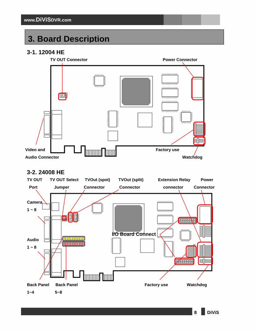
3-1. 12004 HE 8
3-2. 24008 HE 8
3-3. 48016 HE 9
3-4. 96032 HE Slave 9
3-5. 48016 HE D1 10
3-6. I/O Board 11
4. Installation 12
4-1. 12004 HE 12
4-2. 24008 HE 13
4-2-1. Pigtail Type 13
4-2-2. Back Panel Type 14
4-3. 48016 HE 15
4-3-1. Pigtail Type 15
4-3-2. Back Panel Type 16
4-4. 96032 HE Slave 17
4-5. 48016 HE D1 19
4-5-1. Pigtail Type 19
4-5-2. Back Panel Type 20
5. Accessories 21
5-1. Back Panel 21
5-2. Video and Audio Pigtail Cable 22
5-2-1. Pigtail 4ch and 8ch Cable 22
5-2-2. Pigtail 16ch Cable 23
5-3. Sensor Board 23
5-4. USB to RS422/485 Converter 24
5-5. USB to RS422/485 Converter (32ch) 25
Index

2 DiViS
www.DiViSDVR.com
This is a guide book that explains the hardware components and provides a step-by-step installation of DVR board. For the software explanation, please refer to “Installation and User’s Guide”. This guide book is applicable to, among DiViS products, 12004HE, 24008HE, 48016HE, 48016HE D1 and 96032HE Slave boards. The pictures and the name of the products are subject to change; the usage, however, may be similar.
Please contact us through the LiveChat service for any technical questions. Website: https://divisdvr.com
Introduction

3 DiViS
www.DiViSDVR.com
· 1~32 Camera Inputs / Output
Up to 32 camera inputs are available on screen for digital handling.
Normal input condition: 75 Ohm, 1 Volt (p-p)
· 1~32 Sensor Inputs
Up to 32 sensors can be linked to the system
External DC 12 Volt power must be provided to the sensor input from outside.
· 1~8 Digital Outputs (Relay Outputs)
Digital Outputs can be used to activate alarm response devices, such as shutters and sirens.
These outputs can be activated by sensors and motion detection.
· Sound Recording and Two-Way Communication Capabilities
Sound can be recorded with video images. Two-way communication is possible between DiViS main and DiViS
Net or Web, while sound is being recorded.
*Note: Sound recording must be made with an amplified microphone.
· Display Features (w/ Multi-Viewing)
Multi-Viewing display feature allows up to 16 different camera shots to be displayed onscreen at the same
time. Other display features include enlarging all displayed cameras or just one. 32 channel viewing can be
attained with specially configured cards.
· PAN/TILT/ZOOM/FOCUS Capabilities
Each connected camera can be manipulated through the DiViS main program as long as the camera supports
such capabilities. This feature can also be controlled remotely.
· Auto Rebooting System
When DiViS detects an error or malfunction within the system, it will automatically reboot the system in order to
correct it.
· Motion Detection and Sensor Trigger
Detection features make it possible to utilize more efficient recording methods, such as recording only when
movement is detected.
1. Specification of DiViS H.264

4 DiViS
www.DiViSDVR.com
· Scheduled Recording
Scheduling allows the administrator to record with different methods at different time periods. Every
combination of scheduling is available in DiViS program.
· Manual and Auto Backup
Data can be preserved through various formats (DAT, CD, or DVD) and data from specific cameras and/or time
periods can be specifically isolated for backup in various formats as well. Much like scheduled recording,
backup of data can be scheduled as well.
· Digitalized Video Search
Digital playback features include advanced search features, such as searching by text data, and image
extracting, which allows portions of existing video to be isolated and saved as a separate file.
· Network Support (TCP/IP, LAN, Modem Protocol Support)
DiViS supports network access, which allows administrators to log in to DVR main program from DiViS-Net or
any web browser and remotely access all the features that are provided locally.
· Integration with Text data from External Devices
Data from external devices (POS, Access Control, ATM, etc) can be recorded with DVR video images. Our
advanced search features allow users to search the local data using information from external devices when an
event occurs. This guarantees high level of integrity and security.
* Note: 96032HE consists of one of 48016HE and 96032HE Slave
Feature 12004HE 24008HE 48016HE 96032HE Slave 48016HE D1
Camera Input (NTSC/PAL) 1~4Port 1~8Port 1~16 Port 1~32 Port 1~16 Port
Sound Input 1~4Port 1~8Port 1~16 Port 1~32 Port 1~16 Port
Sensor Input 1~4Port 1~16Port 1~16 Port 1~32 Port 1~16 Port
Relay Output 1~4Port 1~4Port 1~4 Port 1~8 Port 1~4 Port
Composite Output 1 Port (NTSC/PAL, Normal)
Image Format H.264
Recording Mode Watch, Normal, Motion Detection, Sensor, scheduled Recording
Remote Control Full remote control PSTN, ISDN,ADSL, LAN and TCP/IP
Back-up DAT, CD, DVD
PAN/TILT/ZOOM/FOCUS RS-232/422/485 Interface
5 DiViS
www.DiViSDVR.com
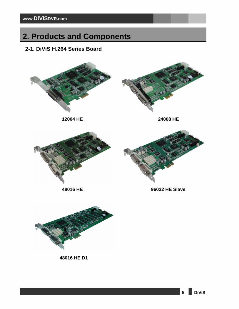
2-1. DiViS H.264 Series Board
12004 HE 24008 HE
48016 HE 96032 HE Slave
48016 HE D1
2. Products and Components
6 DiViS
www.DiViSDVR.com
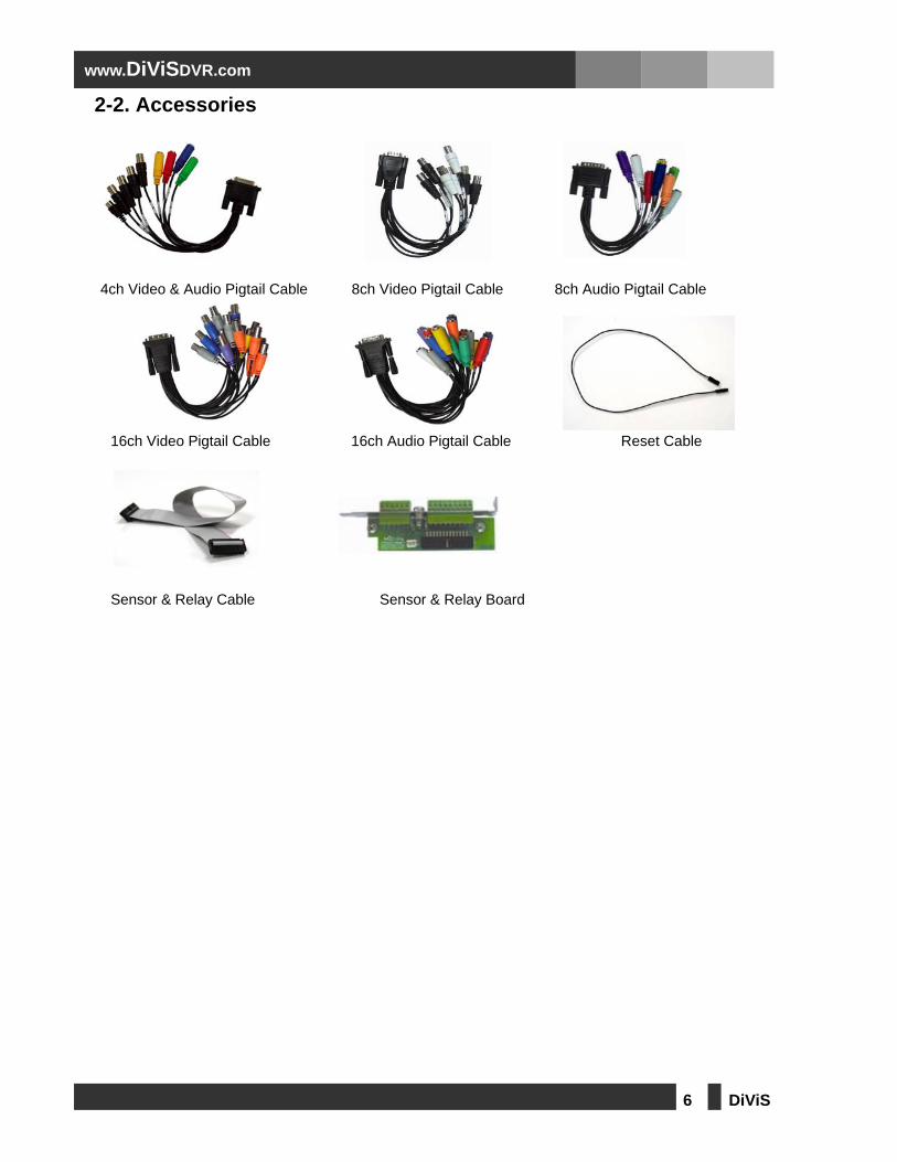
2-2. Accessories 4ch Video & Audio Pigtail Cable 8ch Video Pigtail Cable 8ch Audio Pigtail Cable
16ch Video Pigtail Cable 16ch Audio Pigtail Cable Reset Cable
Sensor & Relay Cable Sensor & Relay Board

7 DiViS
www.DiViSDVR.com
2-3. Optional Accessories
RS422/485 Board RS422/485 Board (32ch) RS422/485 Board Cable
I/O Board Sensor & Relay Cable Sensor Board Video Cable
Back Panel TV-OUT cable 1(for 32ch) TV-OUT cable 2(for 32ch)
8 DiViS
www.DiViSDVR.com
3-1. 12004 HE
TV OUT Connector Power Connector
Video and Factory use
Audio Connector Watchdog
3-2. 24008 HE TV OUT TV OUT Select TVOut (spot) TVOut (split) Extension Relay Power
Port Jumper Connector Connector connector Connector
Camera
1 ~ 8
Audio
1 ~ 8
Back Panel Back Panel Factory use Watchdog
1~4 5~8
3. Board Description
I/O Board Connect

9 DiViS
www.DiViSDVR.com
3-3. 48016 HE TV OUT Select TVOut (spot) TVOut (split) Extension Relay Power
Jumper Connector Connector Connector Connector
Camera
1 ~ 16
Audio
1 ~ 16
Back Panel Factory use Watchdog
Connector
3-4. 96032 HE Slave TV OUT Select TVOut (spot) TVOut (split) Power
Jumper Connector Connector Connector
Camera
17 ~ 32
Audio
17 ~ 32
Back Panel Factory use TVOut Connect
Connector Socket
I/O Board Connect
1 ~ 45 ~ 89 ~ 1213 ~ 16
I/O Board Connect
17 ~ 2021 ~ 2425 ~ 2829 ~ 32

10 DiViS
www.DiViSDVR.com
3-5. 48016 HE D1 Camera TV OUT Select TVOut (spot) Extension Relay Power
1 ~ 16 Jumper Connector Connector Connector
Audio TVOut (spot/split) Back Panel Factory use Watchdog
1 ~ 16 Connector Connector
I/O Board Connect
1 ~ 45 ~ 89 ~ 1213 ~ 16

11 DiViS
www.DiViSDVR.com
3-6. I/O Board

12 DiViS
www.DiViSDVR.com
4-1. 12004 HE
1) Connect 1~4 channel video pigtail cable to the top connector.
2) Connect 1~4 channel audio pigtail cable to the bottom connector.
3) Connect TV-OUT monitor.
4) Connect Power cable
5) Connect watchdog cable. (Black cable must go bottom of the connector)
4. Installation
1
2
3
4
5

13 DiViS
www.DiViSDVR.com
4-2. 24008 HE 4-2-1. Pigtail Type
1) Connect 1~16 channel video pigtail cable to the top connector.
2) Connect 1~16 channel audio pigtail cable to the bottom connector.
3) Connect CCTV monitor.
4) Connect the other side of the I/O cable to the I/O connector.
5) Connect I/O cable to the sensor port.
6) Connect watchdog cable. (Black cable must go bottom of the connector)
7) Connect Power cable
1
2
3
4
5
6
7

14 DiViS
www.DiViSDVR.com
4-2-2. Back Panel Type
1) Back Panel.
2) Sensor Cable.
3) When connecting video cables to back panel, make sure to leave the bottom pin on the back panel and
have white cables facing up.
4) Connect TV-Out cable to the top pin on back panel. (make sure to have the white cable facing up)
5) Connect the other side of the TV-Out cable to the capture board.
6) Connect the video cable with BNC2 label.
7) Connect the remaining cable with BNC2 label.
8) Connect audio pigtail cable.
9) Connect watchdog cable. .(Black cable must go bottom of the connector)
10) Connect Power cable
2 1 1
6
7
8 9
3 4 8 5
3 10

15 DiViS
www.DiViSDVR.com
4-3. 48016 HE 4-3-1. Pigtail Type
6) Connect 1~16 channel video pigtail cable to the top connector.
7) Connect 1~16 channel audio pigtail cable to the bottom connector.
8) Connect CCTV monitor.
9) Connect I/O cable to the sensor port.
10) Connect the other side of the I/O cable to the I/O connector.
11) Connect watchdog cable as shown below. (White cables must face the top)
12) Connect extension relay
13) Connect Power Cable
1
2
3
4
5
6
7
8

16 DiViS
www.DiViSDVR.com
4-3-2. Back Panel Type
1) Back Panel.
2) Sensor Cable.
3) With white cable facing up, connect video cables to back panel leaving just one bottom pin..
4) Connect TV-Out cable to the top pin of back panel. (The white cable must face the top)
5) Connect the other side of the TV-Out cable to the capture board.
6) Connect the video cable labeled BNC2 here.
7) Connect the remaining cable labeled BNC2 here.
8) Connect the video cable labeled BNC9 here.
9) Connect the remaining cable labeled BNC9 here.
10) Connect audio pigtail cable.
11) Connect watchdog cable as shown below. (The white cable must face the top)
2
1 1
6
7
8
9
3 4
8 5
3
10
11

17 DiViS
www.DiViSDVR.com
4-4. 96032 HE Slave
6 5
6
7
8
11
5 10 5 9
1
2
3
4

18 DiViS
www.DiViSDVR.com
1) Connect 1~16 channel video pigtail cable to the top connector of the master board.
2) Connect 1~16 channel audio pigtail cable to the bottom connector of the master board.
3) Connect 17~32 channel video pigtail cable to the top connector of the slave board.
4) Connect 17~32 channel audio pigtail cable to the bottom connector of the slave board.
5) Connect TV-out cable to the master board.
6) Connect the other side of the TV-out cable to the master connector on TV-Out board.
7) Connect TV-out cable to the slave board.
8) Connect the other side of the TV-out cable to the slave connector on TV-Out board.
9) Make sure to have the white cable of the TV-out cable facing up on the TV-Out board.
10) Make sure to have the white cable of the TV-out cable facing down on the Slave board.
11) Connect watchdog cable.

19 DiViS
www.DiViSDVR.com
4-5. 48016 HE D1 4-5-1. Pigtail Type
1) Connect 1~16 channel video pigtail cable to the top connector.
2) Connect 1~16 channel audio pigtail cable to the bottom connector.
3) Connect CCTV monitor.
4) Connect I/O cable to the sensor port.
5) Connect the other side of the I/O cable to the I/O connector.
6) Connect watchdog cable as shown below. (White cables must face the top)
7) Connect Power Cable
1
2
3
4
5
6
7

20 DiViS
www.DiViSDVR.com
4-5-2. Back Panel Type
1) Back Panel.
2) Sensor Cable.
3) With white cable facing up, connect video cables to back panel leaving just one bottom pin..
4) Connect TV-Out cable to the top pin of back panel. (The white cable must face the top)
5) Connect the other side of the TV-Out cable to the capture board.
6) Connect the video cable labeled BNC2 here.
7) Connect the remaining cable labeled BNC2 here.
8) Connect the video cable labeled BNC9 here.
9) Connect the remaining cable labeled BNC9 here.
10) Connect audio pigtail cable.
11) Connect watchdog cable as shown below. (The white cable must face the top)
12) Connect power cable
2
1 1
6
7
8
9
3 4
8 5
3
10
11
12

21 DiViS
www.DiViSDVR.com
5-1. Back Panel
Sensor & Relay (Digital I/O)Sensor Input 0~15 1~16
Input Common 0~1 17, 18
Relay Output 0~3 19~22
Output Common 0~1 23, 24
Camera I/O Camera Ground 3, 5, ~ 31, 33
Camera Signal 4, 6, ~ 32, 34
TV Out Ground 1
TV Out Signal 2
5. Accessories

22 DiViS
www.DiViSDVR.com
5-2. Video and Audio Pigtail Cable 5-2-1. Pigtail 4ch and 8ch Cable
Video Pigtail cable Audio Pigtail cable 1~4 BNC : Black BNC 1 : Blue con 2 : Yellow con
3 : Green con
4 : Red con
Video Pigtail cable Audio Pigtail cable 1~4 BNC : Black BNC 1 : Blue con 5 : Gray con
5~8 BNC : White BNC 2 : Yellow con 6 : Purple con
3 : Green con 7 : White con
4 : Red con 8 : Orange con

23 DiViS
www.DiViSDVR.com
5-2-2. Pigtail 16ch Cable
Video Pigtail cable Audio Pigtail cable 1 ~ 4 : Blue BNC 1, 9 : Red con 5, 13 : Blue con
5 ~ 8 : Orange BNC 2, 10 : Orange con 6, 14 : Violet con
9 ~ 12 : Violet BNC 3, 11 :Yellow con 7, 15 : Gray con
13 ~ 16 : Gray BNC 4, 12 : Green con 8, 16 : White con
5-3. Sensor Board
Sensor port pin number 1 ~ 16 : Signal input
G : Ground
R1, R2, R3, R4 : Relay output

24 DiViS
www.DiViSDVR.com
5-4. USB to RS422/485 Converter
1) Connect to internal USB header on system motherboard.
2) Connect the other side to RS422/485 Board.
3) Connect a power source to any one of these power sockets.
RS-485 Mode RS-422 Mode
1 2
3
2

25 DiViS
www.DiViSDVR.com
5-5. USB to RS422/485 Converter (32ch)
USB to RS422/485 Converter + TV-OUT board for 32 channels
1) Connect to internal USB header on system motherboard.
2) Connect the other side to RS422/485 Board.
3) Connect a power source to any one of these power sockets.
4) Connect to the TV-out cable
5) TV-Out connector: Connect it to the master board.
6) TV-Out connector: Connect it to the slave board.
7) Connect it to the slave board.
2 2 1
3
6
7
4 5