Embed Size (px)
Citation preview

Rev. 1.0
Digital Video Security System
Digital Video Recorder
www.DiViSdvr.com
DiViS DVR.com *All contents of this document may change without prior notice, and actual product appearance may differ from depicted herein.
DiViS DVR
Hardware Installation Guide
HD-SDI Series

1 DiViS
www.DiViSDVR.com
1. Specification of DiViS HD 3
2. Installation Notes 5
2-1. Recommendation for
12004HDH & 24008HDH 5
2-2. Recommendation for
48016HDH 5
3. Products and Components 6
3-1. DiViS HD Series Board 6
3-2. Optional Accessories 6
4. Board Description 7
4-1. 12004HDH 7
4-2. 24008HDH 8
4-3. 48016HDH 10
4-4. I/O Board 12
5. Installation 13
5-1. 12004HDH Installation 13
5-2. 24008HDH Installation 14
5-3. 48016HDH Installation 15
6. Accessories 17
6-1. RS422/485 Converter 17
Index

2 DiViS
www.DiViSDVR.com
This is a guide book that explains the hardware components and provides a step-by-step installation of DVR board. For the software explanation, please refer to “Installation and User’s Guide”. This guide book is applicable to, among DiViS products, 12004HDH, 24008HDH & 48016HDH board. The pictures and the name of the products are subject to change; however, the usage may be similar.
Please contact us through the LiveChat service for any technical questions. Website: https://divisdvr.com
Introduction

3 DiViS
www.DiViSDVR.com
ㆍ 1~16 Camera inputs/output
Up to 16 camera inputs are available on screen for digital handling.
- Normal input condition: 75 Ohm, SMPTE 292M
ㆍ 1~16 Sensor inputs
Up to 16 sensors can be linked to the system.
- Power supply of DC 12 Volt is required from outside.
ㆍ 1~4 Digital outputs (Relay outputs)
Digital Outputs can be used to activate things like shutters and sirens, and activation can be linked to
sensor and motion detection.
ㆍ Sound recording and Two-way communication capability
Sound can be recorded with video images. Two-way communication is possible between DiViS main
and DiViS-Net.
ㆍ Display feature (with Multi-viewing)
Multi-Viewing allows 1, 4, 6, 9, 10, 16 different camera shots to be displayed onscreen at the same time.
Other display features include enlarging all displayed cameras or just one.
ㆍ PAN/TILT/ZOOM/FOCUS Capabilities
Each connected camera can be manipulated through the DiViS main program as long as each
camera supports such capabilities.
ㆍ Auto Rebooting System
When DiViS detects an error or malfunction within the system, it will automatically reboot the
system in order to correct it.
ㆍ Motion Detection and Sensor Trigger
Detection features make it possible to record images only when movement is detected, preserving
volume space and maximizing the use of physical storage space.
ㆍ Scheduled Recording
Scheduling allows the administrator to record images only during designated time periods, if so desired.
Every combination of scheduling is available in the DiViS program.
ㆍ Manual and Auto Backup
1. Specification of DiViS HD

4 DiViS
www.DiViSDVR.com
Data can be preserved through various formats (DAT, CD, or DVD) and data from specific cameras
and/or time periods can be specifically isolated for backup as well. Much like scheduled recording,
backup of data can be scheduled as well.
ㆍ Digitalized Video Search
Recorded data features digital playback for each camera simultaneously or one at a time. Playback
features include advanced search features and image extracting, which allows portions of existing video
to be extracted and saved as a separate file.
ㆍ Network Support (PSTN, TCP/IP, LAN ,Modem Protocol Support)
DiViS supports network access, which allows administrators to login to DiViS main and remotely access
all the features provided locally.
ㆍ POS, Access Control, ATM Support
Record data from external devices(POS, Access Control, ATM, etc)with DVR video images. Text
Search allows to search data from external devices with DVR video image when event occurs. This will
raise the level of integrity and security
Function 12004HDH 24008HDH 48016HDH Camera Input 1~4 Port HD 1~8 Port HD 1~16 Port HD
Sound Input 2 Channel
Sensor Input 16 Port
Relay Output 4 Port
Image Format Hardware H.264
Recording Mode Watch, Normal, Motion Detection, Sensor, scheduled Recording
Remote Control Full remote control PSTN, ISDN,ADSL, LAN and TCP/IP
Back-up DAT, CD, DVD
PAN/TILT/ZOOM/FOCUS RS-232/422/485 Interface
5 DiViS
www.DiViSDVR.com
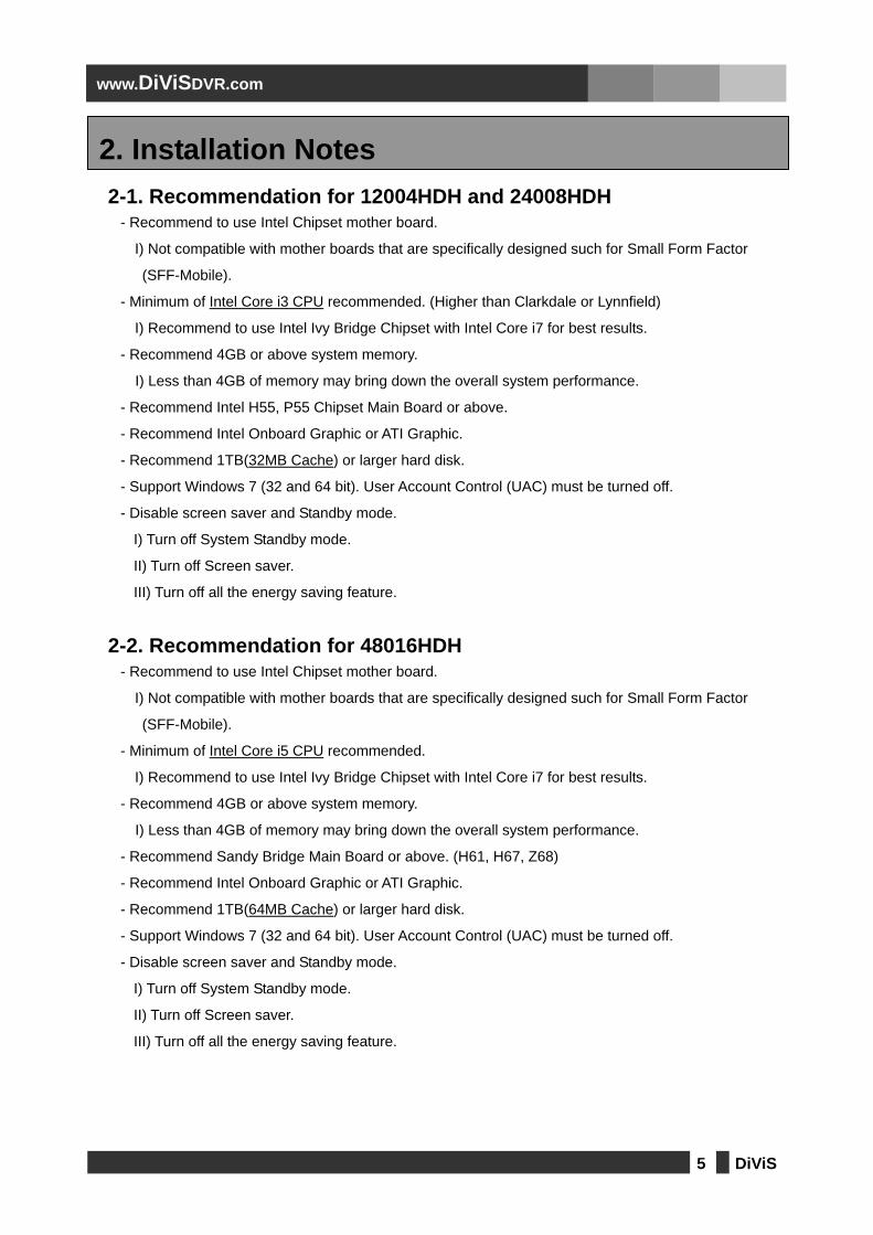
2-1. Recommendation for 12004HDH and 24008HDH
- Recommend to use Intel Chipset mother board.
I) Not compatible with mother boards that are specifically designed such for Small Form Factor
(SFF-Mobile).
- Minimum of Intel Core i3 CPU recommended. (Higher than Clarkdale or Lynnfield)
I) Recommend to use Intel Ivy Bridge Chipset with Intel Core i7 for best results.
- Recommend 4GB or above system memory.
I) Less than 4GB of memory may bring down the overall system performance.
- Recommend Intel H55, P55 Chipset Main Board or above.
- Recommend Intel Onboard Graphic or ATI Graphic.
- Recommend 1TB(32MB Cache) or larger hard disk.
- Support Windows 7 (32 and 64 bit). User Account Control (UAC) must be turned off.
- Disable screen saver and Standby mode.
I) Turn off System Standby mode.
II) Turn off Screen saver.
III) Turn off all the energy saving feature.
2-2. Recommendation for 48016HDH
- Recommend to use Intel Chipset mother board.
I) Not compatible with mother boards that are specifically designed such for Small Form Factor
(SFF-Mobile).
- Minimum of Intel Core i5 CPU recommended.
I) Recommend to use Intel Ivy Bridge Chipset with Intel Core i7 for best results.
- Recommend 4GB or above system memory.
I) Less than 4GB of memory may bring down the overall system performance.
- Recommend Sandy Bridge Main Board or above. (H61, H67, Z68)
- Recommend Intel Onboard Graphic or ATI Graphic.
- Recommend 1TB(64MB Cache) or larger hard disk.
- Support Windows 7 (32 and 64 bit). User Account Control (UAC) must be turned off.
- Disable screen saver and Standby mode.
I) Turn off System Standby mode.
II) Turn off Screen saver.
III) Turn off all the energy saving feature.
2. Installation Notes

6 DiViS
www.DiViSDVR.com
3-1. DVR Board
12004HDH
24008HDH 48016HDH
3-2. Optional Accessories
Sensor Port Sensor Cable
RS-485 Board USB RS-485 board cable
3. Products and Components

7 DiViS
www.DiViSDVR.com
4-1. 12004HDH
1) BNC connector: Connect BNC cable 1 ch.
2) BNC connector: Connect BNC cable 2 ch.
3) BNC connector: Connect BNC cable 3 ch.
4) BNC connector: Connect BNC cable 4 ch.
5) Factory use
6) I/O Board connector: Connect I/O Board.
7) Power connector
8) Extension Relay connector: Connect extension relay.
9) Watchdog connector.
4. Board Description
1
3
4
6
9
6 7
7
2
7 6
5
8 8

8 DiViS
www.DiViSDVR.com
4-2. 24008HDH
1
3
4
6
9
6 7
7
2
7 6
5
8 8
10
12
13
6 6 7
15
11 14

9 DiViS
www.DiViSDVR.com
1) BNC connector: Connect BNC cable 1 ch.
2) BNC connector: Connect BNC cable 2 ch.
3) BNC connector: Connect BNC cable 3 ch.
4) BNC connector: Connect BNC cable 4 ch.
5) Factory use
6) I/O Board connector: Connect I/O Board.
7) Power connector
8) Extension Relay connector: Connect extension relay.
9) Watchdog connector.
10) BNC connector: Connect BNC cable 5 ch.
11) BNC connector: Connect BNC cable 6 ch.
12) BNC connector: Connect BNC cable 7 ch.
13) BNC connector: Connect BNC cable 8 ch.
14) Factory use
15) Power connector

10 DiViS
www.DiViSDVR.com
4-3. 48016HDH
1
3
4
6
9
6 7
7
2
7 6
5 8 8
10
12
13
14
11
15
17
18
19
16
20
22
23
24
21

11 DiViS
www.DiViSDVR.com
1) BNC connector: Connect BNC cable 1 ch.
2) BNC connector: Connect BNC cable 2 ch.
3) BNC connector: Connect BNC cable 3 ch.
4) BNC connector: Connect BNC cable 4 ch.
5) Factory use
6) I/O Board connector: Connect I/O Board.
7) Power connector
8) Extension Relay connector: Connect extension relay.
9) Watchdog connector.
10) BNC connector: Connect BNC cable 5 ch.
11) BNC connector: Connect BNC cable 6 ch.
12) BNC connector: Connect BNC cable 7 ch.
13) BNC connector: Connect BNC cable 8 ch.
14) Power connector
15) BNC connector: Connect BNC cable 9 ch.
16) BNC connector: Connect BNC cable 10 ch.
17) BNC connector: Connect BNC cable 11 ch.
18) BNC connector: Connect BNC cable 12 ch.
19) Power connector
20) BNC connector: Connect BNC cable 13 ch.
21) BNC connector: Connect BNC cable 14 ch.
22) BNC connector: Connect BNC cable 15 ch.
23) BNC connector: Connect BNC cable 16 ch.
24) Power connector

12 DiViS
www.DiViSDVR.com
4-4. I/O board
Bottom side Top side
1) I/O Connector: Connect I/O Cable.
2) Board Connector: Connect to the upper I/O board connector of the capture board.
3) Board Connector: Connect to the lower I/O board connector of the capture board.
1 1
2
3

13 DiViS
www.DiViSDVR.com
5-1. 12004HDH Installation
1) Connect 1~4 channel video BNC cable to the connector.
2) Connect Power cable
3) Connect I/O cable to the sensor port.
4) Connect the other side of the I/O cable to the I/O connector.
5) Connect watchdog cable. (Black cable must go bottom of the connector)
5. Installation
1
3
2
4
5

14 DiViS
www.DiViSDVR.com
5-2. 24008HDH Installation
1) Connect 1~4 channel video BNC cable to the connector.
2) Connect Power cable
3) Connect I/O cable to the sensor port.
4) Connect the other side of the I/O cable to the I/O connector.
5) Connect watchdog cable. (Black cable must go bottom of the connector)
6) Connect 1~4 channel video BNC cable to the connector.
7) Connect Power cable
1
3 2
4
5
6
7

15 DiViS
www.DiViSDVR.com
5-3. 48016HDH Installation
1
3 2
4
5
6
7
8
9

16 DiViS
www.DiViSDVR.com
1) Connect 1~4 channel video BNC cable to the connector.
2) Connect Power cable
3) Connect I/O cable to the sensor port.
4) Connect the other side of the I/O cable to the I/O connector.
5) Connect watchdog cable. (Black cable must go bottom of the connector)
6) Connect 4~8 channel video BNC cable to the connector.
7) Connect Power cable
8) Connect 9~12 channel video BNC cable to the connector.
9) Connect Power cable
10) Connect 13~16 channel video BNC cable to the connector.
11) Connect Power cable
10
11

17 DiViS
www.DiViSDVR.com
6-1. USB to RS 422/485 Converter
PTZ Device Port Convertor
1) Connect to a COM port on system motherboard.
2) Connect the other side of this cable to RS-485 Board.
3) They are power sockets. It requires connection to only one of them.
RS-485 Mode RS-422 Mode
6. Accessories
1 2
3
2