Embed Size (px)
Citation preview

Distribution Transformer
InstructorEngr. Muhammad Yaseen

Introduction of Distribution Transformer In general distribution transformers are used to reduce primary
system voltages (2.4-34.5kV) to utilization voltages (120-600V).
IEC (International electrotechnical comission) standards do not distinguish between distribution transformers and power transformer. They are all power transformers in the sense that their purpose is to transmit power from one voltage level to another.
Traditionally, transformers that transform the voltage down to the domestic consumer voltage (usually 400V or less) are called distribution transformers.

Common for most transformers regardless of size and application is the basic physics and the dominant materials, like: Special types of thin magnetic steel plates in the core, which provides the necessary
strong magnetic field because of the unique magnetic properties of iron; Copper or aluminum as conductor materials in the windings; Cellulose products like high density paper and pressboard as solid insulation materials
has been and with few exceptions still is dominant; Mineral oil is the dominant insulating fluid, which also has cooling function.
In practical transformer design the manufacturer has the choice between two different basic concepts: Core type transformer Shell type transformer
In a nutshell we can say that while the winding of core –type enclose the core, the core of shell-type encloses the windings.
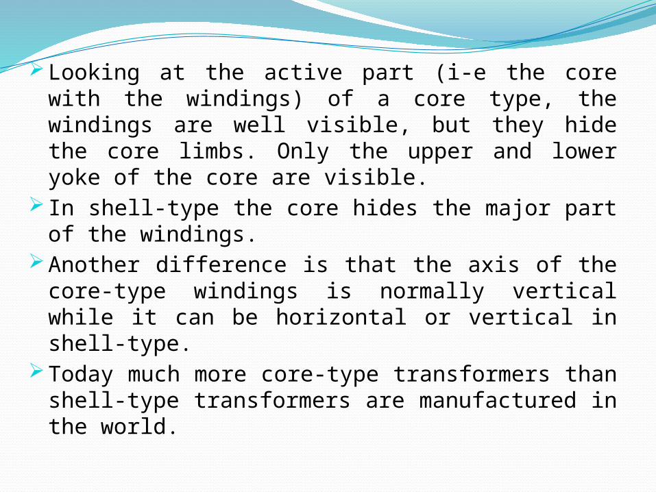
Looking at the active part (i-e the core with the windings) of a core type, the windings are well visible, but they hide the core limbs. Only the upper and lower yoke of the core are visible.
In shell-type the core hides the major part of the windings.
Looking at the active part (i-e the core with the windings) of a core type, the windings are well visible, but they hide the core limbs. Only the upper and lower yoke of the core are visible.
In shell-type the core hides the major part of the windings.Another difference is that the axis of the core-type windings is
normally vertical while it can be horizontal or vertical in shell-type.
Today much more core-type transformers than shell-type transformers are manufactured in the world.


A wound type of core used in single-phase distribution transformers is shown in below
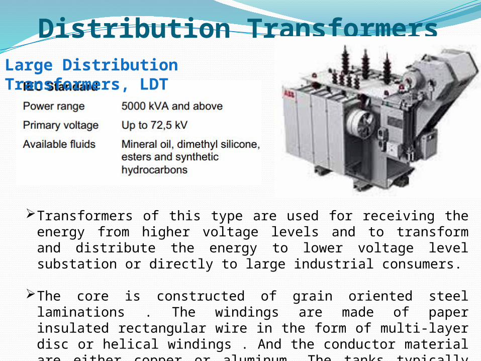
Distribution TransformersLarge Distribution Transformers, LDT
Transformers of this type are used for receiving the energy from higher voltage levels and to transform and distribute the energy to lower voltage level substation or directly to large industrial consumers.
The core is constructed of grain oriented steel laminations . The windings are made of paper insulated rectangular wire in the form of multi-layer disc or helical windings . And the conductor material are either copper or aluminum. The tanks typically have radiators.

Distribution TransformersSmall Distribution Transformers, SDT
Transformers of this type are used to step down three-phase high voltage to low voltage for energy distribution , mainly in the countryside or low-density populated areas.
The transformers are three phase oil immersed hermetically(air tight) sealed, adaptable for pole mounting or assembly in substations.
On customer request, the transformer can be equipped with an oil conservator.Hot dip zinc coating is often the preferred surface treatment for outdoor
applications.
Distribution Transformers
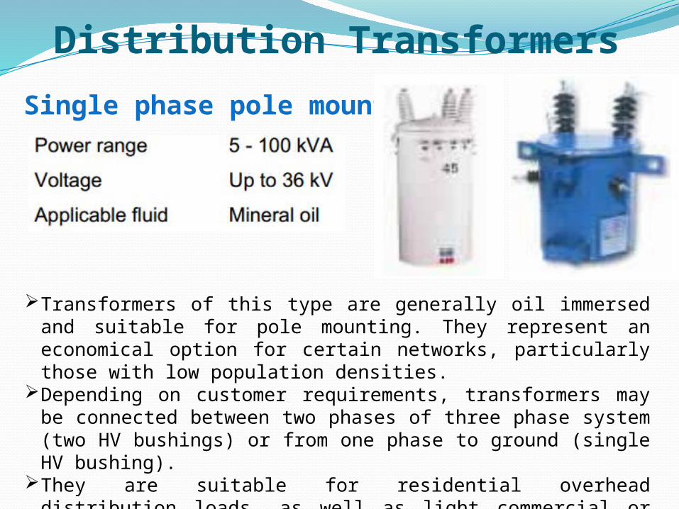
Single phase pole mounted
Transformers of this type are generally oil immersed and suitable for pole mounting. They represent an economical option for certain networks, particularly those with low population densities.
Depending on customer requirements, transformers may be connected between two phases of three phase system (two HV bushings) or from one phase to ground (single HV bushing).
They are suitable for residential overhead distribution loads, as well as light commercial or industrial loads.
Distribution TransformerTypes of Distribution TransformerThere are several types of transformer used in the distribution
system. Such as single phase transformer, three phase transformer, pole mounted transformer, pad mounted transformer, and underground transformer.
What is Voltage Regulation?The voltage regulation is the percentage of voltage difference
between no load and full load voltages of a transformer with respect to its full load voltage.

Distribution TransformerExplanation of voltage regulation of transformer If an Electrical power transformer is an open circuited, means load
is not connected with secondary terminals. In this situation, the secondary terminal voltage of the transformer will be its secondary induced emf E2.
Whenever full load is connected to the secondary terminals of the transformer, rated current I2 flows through the secondary circuit and voltage drop comes into picture. At this situation, primary winding will also draw equivalent full load current from source.
The voltage drop in the secondary is I2Z2 where Z2 is the secondary impedance of transformer.

Distribution TransformerNow if at this loading condition, any one measures the voltage
between secondary terminals, he or she will get voltage V2 across load terminals which is obviously less than no load secondary voltage E2 and this is because of I2Z2 voltage drop in the transformer.
Expression of voltage regulation of transformerExpression of Voltage Regulation of Transformer, represented in
percentage, is

Tap Changer of Transformer

Distribution TransformerLosses in distribution transformerAs the electrical transformer is a static device, mechanical loss in
transformer normally does not come into picture. We generally consider only electrical losses in transformer. Loss in any machine is broadly defined as difference between input power and output power.
When input power is supplied to the primary of transformer, some portion of that power is used to compensate core losses in transformer i.e. Hysteresis loss in transformer and Eddy current loss in transformer core and some portion of the input power is lost as I2R loss and dissipated as heat in the primary and secondary windings, because these windings have some internal resistance in them.

Distribution Transformerhe first one is called core loss or iron loss in transformer and the
later is known as ohmic loss or copper loss in transformer.Another loss occurs in transformer, known as Stray Loss, due to
Stray fluxes link with the mechanical structure and winding conductors.
Copper Loss in TransformerCopper loss is I2R loss, in primary side it is I1
2R1 and in secondary side it is I2
2R2 loss, where I1 & I2 are primary & secondary current of transformer and R1 & R2 are resistances of primary & secondary winding. As the both primary & secondary currents depend upon load of transformer, copper loss in transformer vary with load.

Distribution TransformerCore Losses in Transformer
Hysteresis loss and eddy current loss, both depend upon magnetic properties of the materials used to construct the core of transformer and its design. So these losses in transformer are fixed and do not depend upon the load current. So core losses in transformer which is alternatively known as iron loss in transformer can be considered as constant for all range of load.
Hysteresis loss in transformer is denoted as,

Distribution Transformer
Distribution TransformerEfficiency of Distribution Transformer
The efficiency of transformer is defined as the ratio between output power to input power of the transformer at full load condition, but in case of a distribution transformer, the concept is a little bit different as the possibility of running a distribution transformer at its full load condition is nearly nil.
In this concept, we use the ratio of total energy delivered by the transformer to the total energy fed to the transformer, during a 24 hrs span of time instead of ratio of power output and input of the transformer. Hence, all day efficiency is determined as, total KWh at the secondary of the total KWh at the primary of the transformer for a long specific period preferably 24 hrs. i.e,

Distribution Transformer
This is very much use full to judge the performance of a distribution transformer, whose primary is connected to the system forever, but secondary load varies tremendously throughout the day.

Distribution TransformerConstruction of Silica Gel Breather
The silica gel breather of transformer is very simple in the aspect of design. It is nothing but a pot of silica gel through which, air passes during breathing of transformer. The silica gel is a very good absorber of moisture. Freshly regenerated gel is very efficient, it may dry down air to a dew point of below − 40°C. A well maintained silica gel breather will generally operate with a dew point of − 35°C as long as a large enough quantity of gel has been used. The picture shows a silica gel breather of transformer.
![trtr trn tru tr[] ujosephschwartzdermatology.com/wp-content/uploads/... · trtr UEI trtr E] utr E] Y-ES tr tr B D tr tr tr tr tr NO tr EI tr u u u EI E tr OlherSystemic: Diobetes](https://img.pdfslide.us/doc/110x75/5f655dabeca5702d4204d061/trtr-trn-tru-tr-ujosep-trtr-uei-trtr-e-utr-e-y-es-tr-tr-b-d-tr-tr-tr-tr-tr-no.jpg)


![Revision and Exam Tips - New SMART website · =====trtrt]=-tr-trtrtrtrtrtr-tr F 1F]ilflfrritfltrft tr-trtr=tr tr=tr==tr tr-tlF-lflft 71 trtr=trtrtr=tr trtrtrtrtr=trtr trtrtrtrtr==tr](https://img.pdfslide.us/doc/110x75/5ed679a2e7ed90307a0783ea/revision-and-exam-tips-new-smart-trtrt-tr-trtrtrtrtrtr-tr-f-1filflfrritfltrft.jpg)