Embed Size (px)
Citation preview
Part 2 – Reference
DISTRIBUTION CONSTRUCTION STANDARDS HANDBOOK
HB01-2007
Pa r t 2 – Re f e r ence
Drawing Register
Number Revision Description
R01 F Pole Bolt Details
R02/1 B Bonding - Intermediate
R02/2 B Bonding - Strain
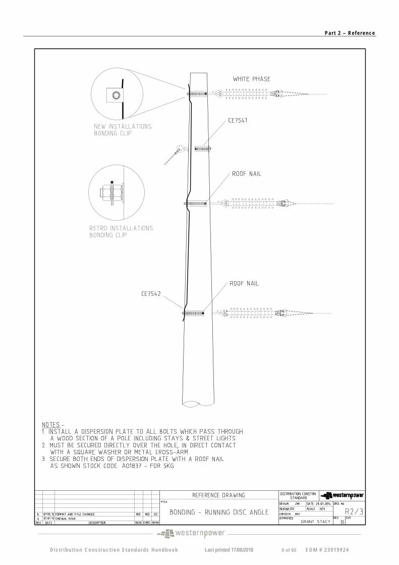
R02/3 B Bonding - Running Disc Angle
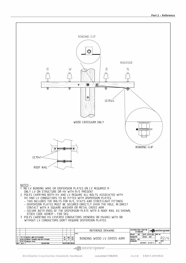
R02/4 G Bonding - Wood LV Cross-arm
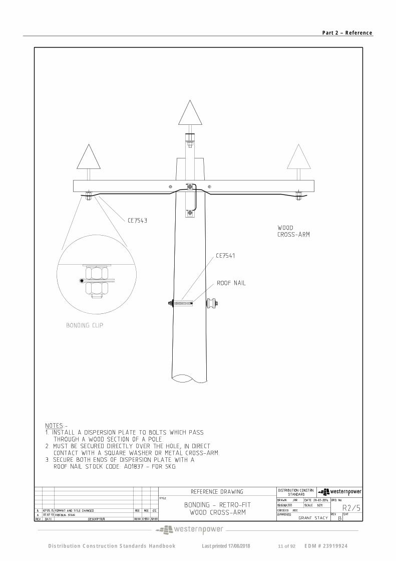
R02/5 B Bonding - Retrofit Wood Cross-arm
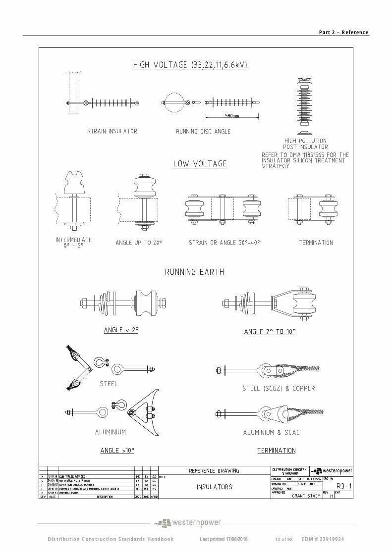
R03-1 H Insulators
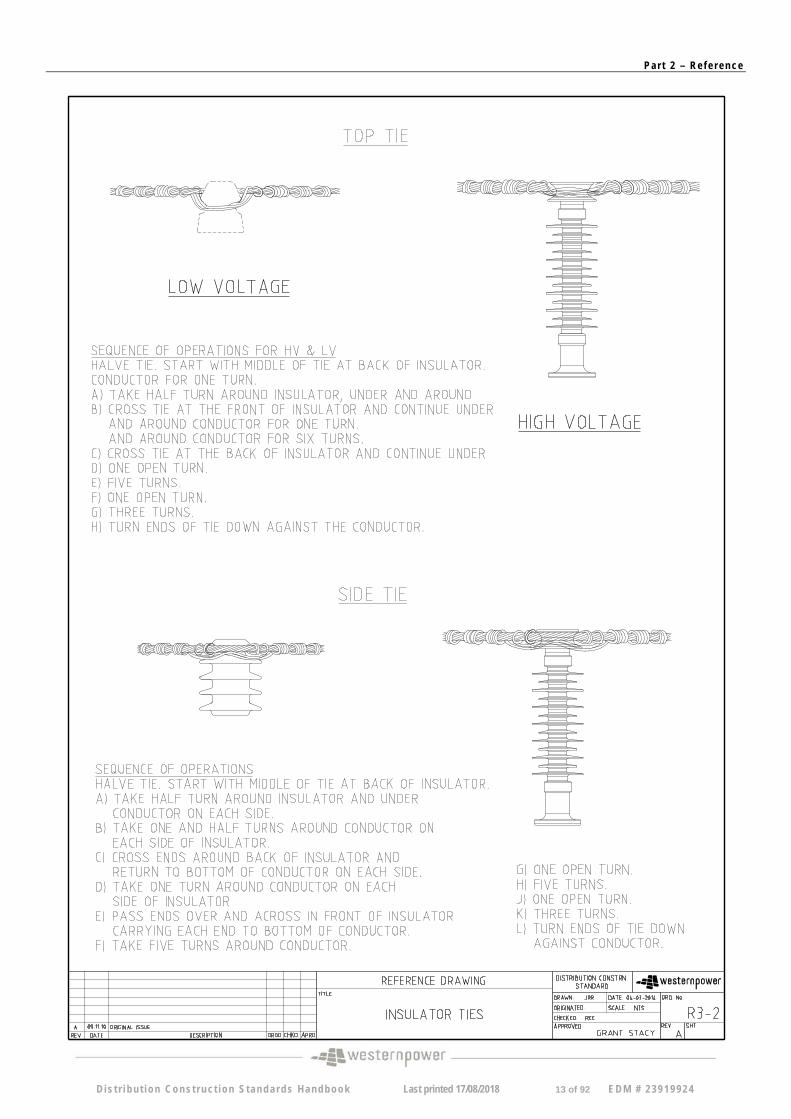
R03-2 A Insulator Ties
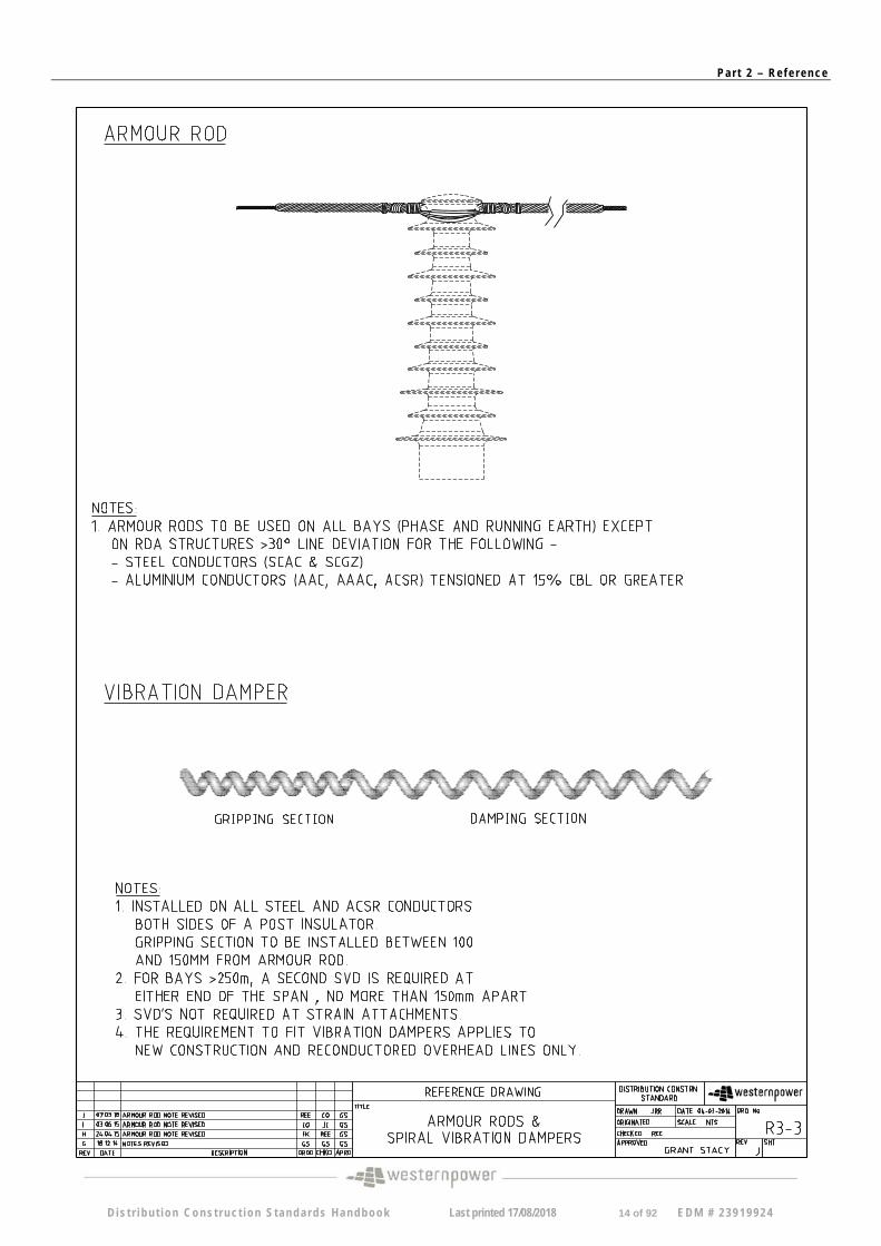
R03-3 J Armour Rods and Spiral Vibration Dampers
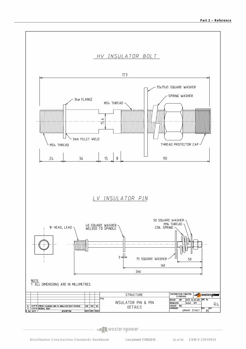
R04 B Insulator Pin & Pin Details
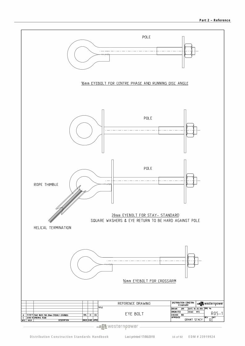
R05-1 D Eyebolt
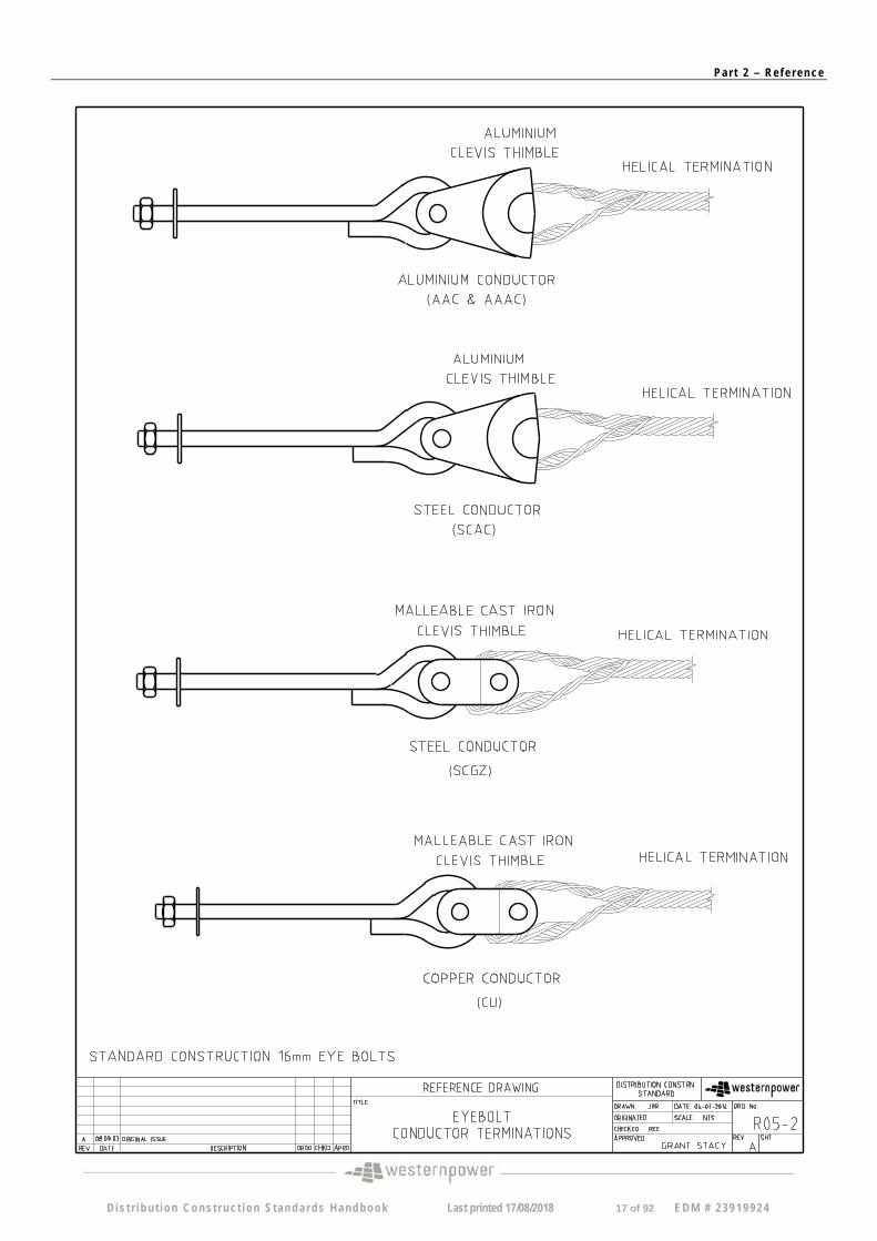
R05-2 A Eyebolt, Conductor Terminations
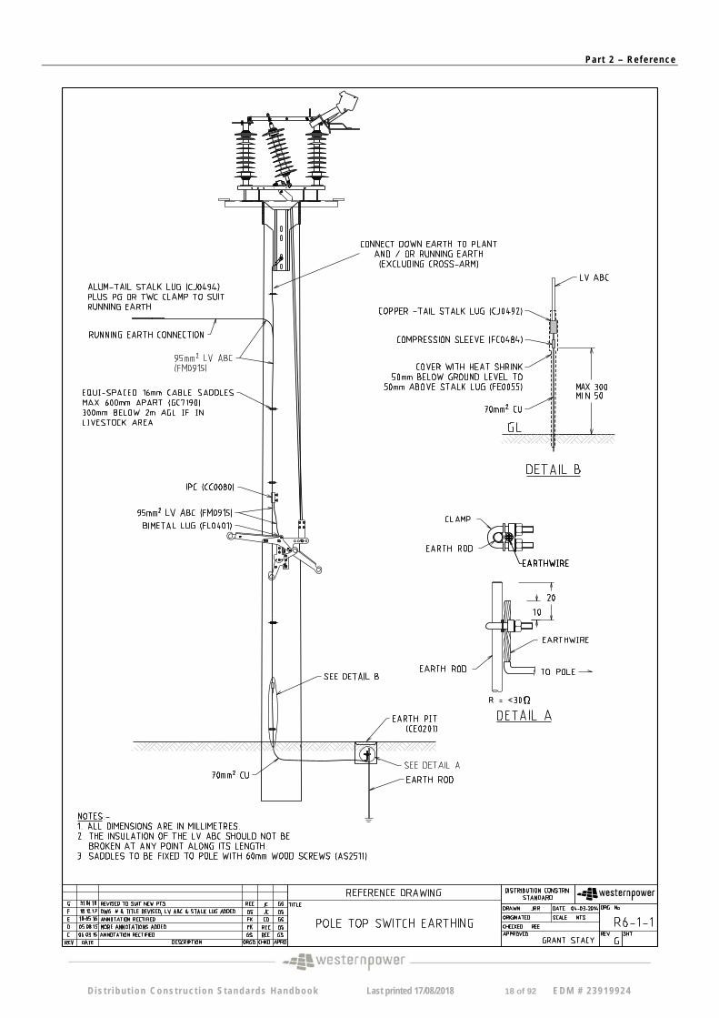
R06-1-1 G Pole top switch Earthing
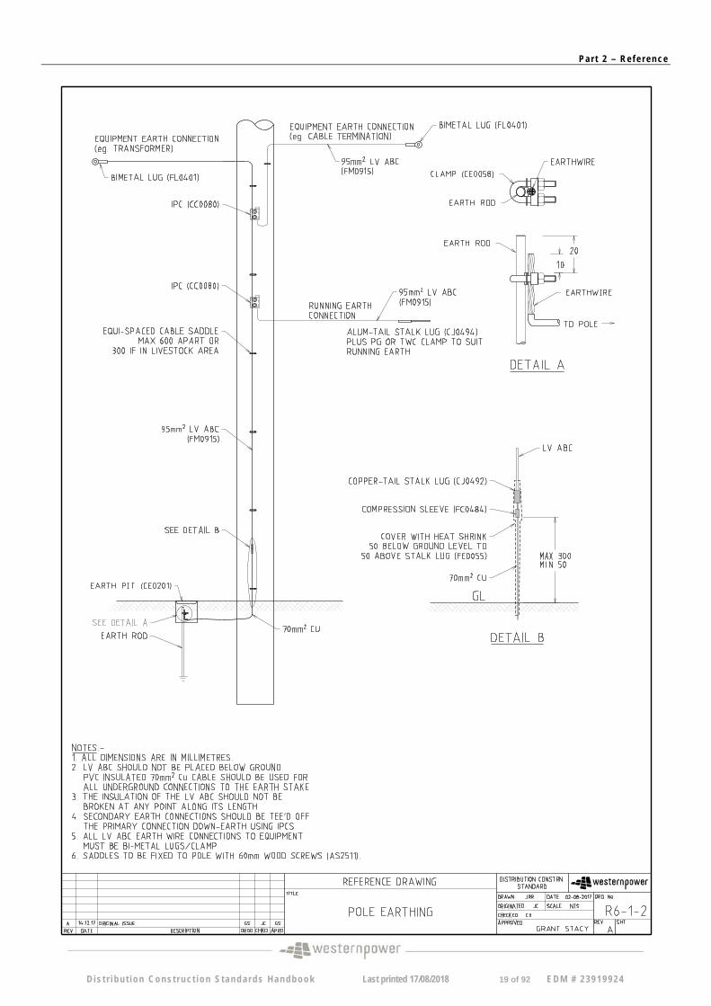
R06-1-2 A Pole Earthing
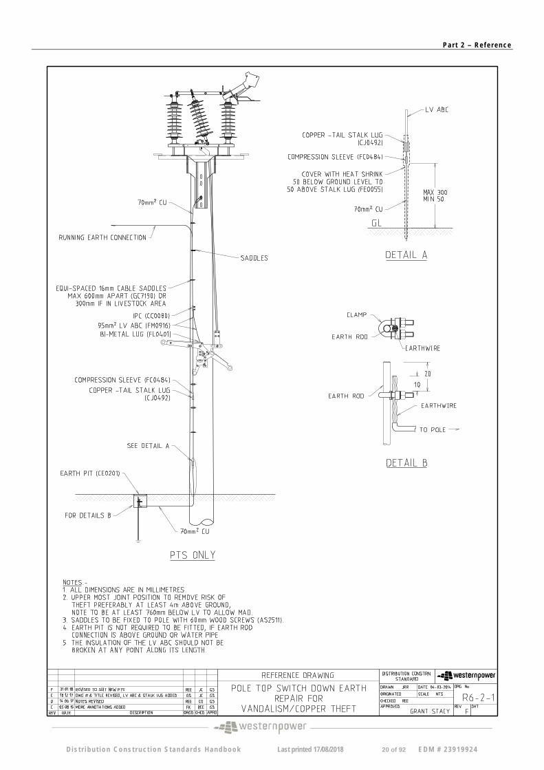
R06-2-1 F PTS Down Earth Repair for Vandalism/Copper Theft
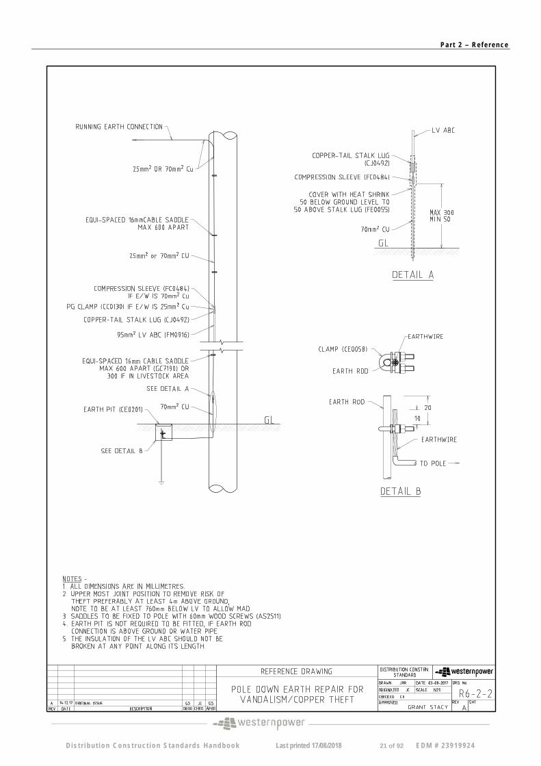
R06-2-2 A Pole Down Earth Repair for Vandalism/Copper Theft
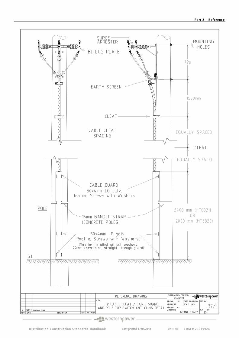
R07-1 C HV Overhead Mains To Cable, Cable Guard, and Cleat Details
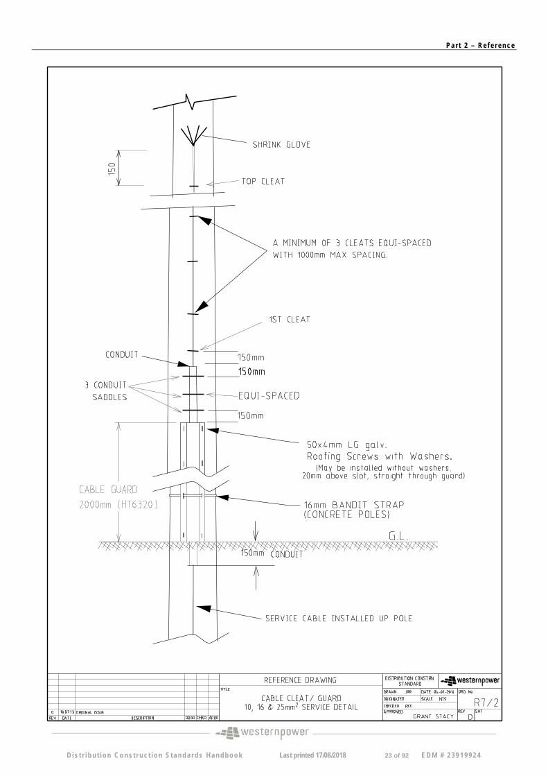
R07-2 B 10,16 and 25mm Service cable cleat/guard fixing details
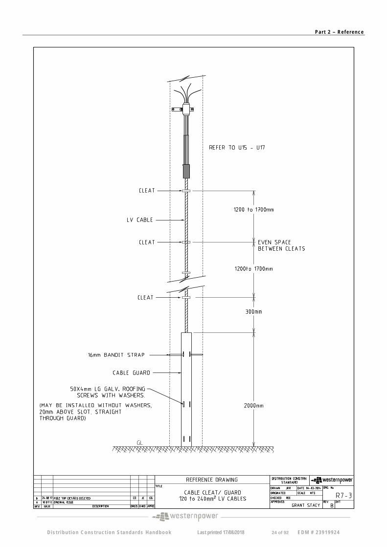
R07-3 B Cable Cleat/Guard 120 to 240mm sq LV cables
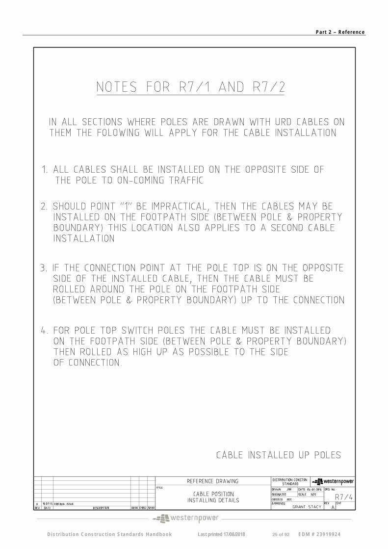
R07-4 B Cable Position Installing Details
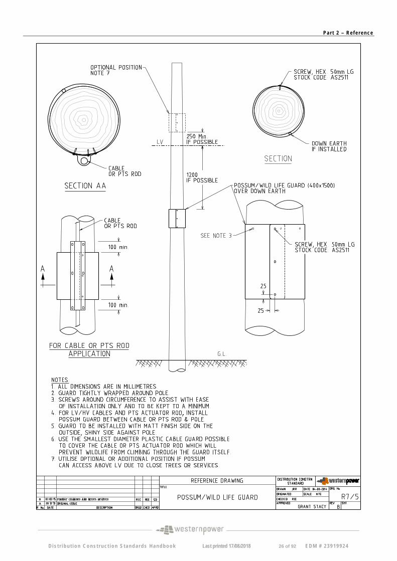
R07-5 B Possum / Wild life guard
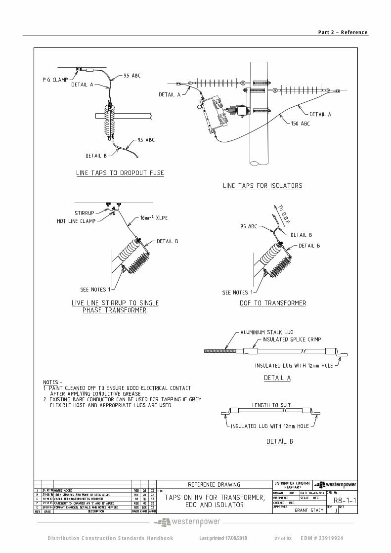
R08-1-1 J ABC Taps For Transformer, and Cable Termination
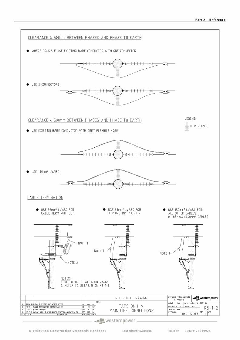
R08-1-2 F Taps on HV Main Line Connections
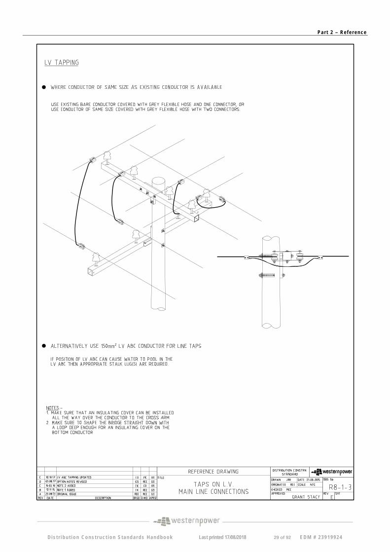
R08-1-3 E Taps on LV Main Line Connections
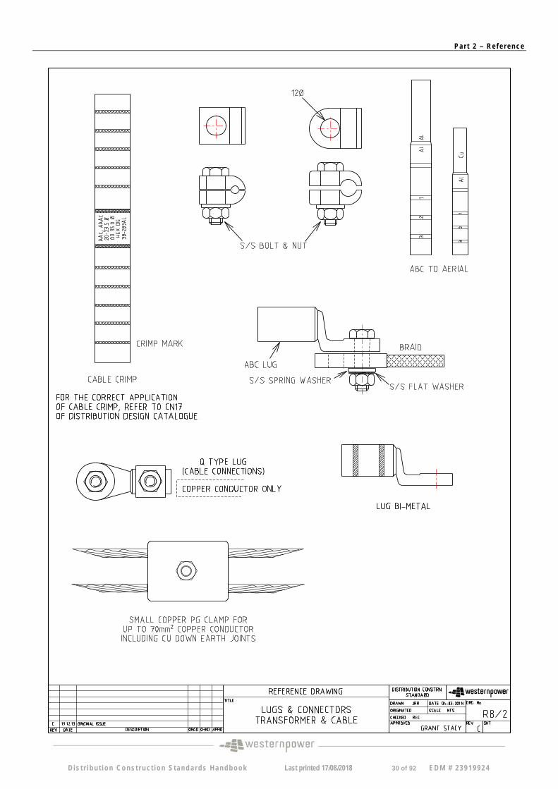
R08-2 C Lugs & Connectors, Transformer & Cable
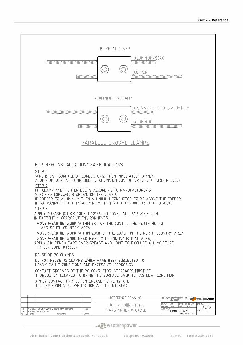
R08-3 F Lugs & Connectors, Transformer & Cable
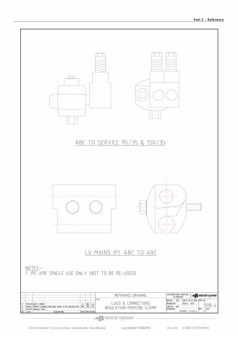
R08-4 F Lugs & Connectors, Insulation Piercing Clamp
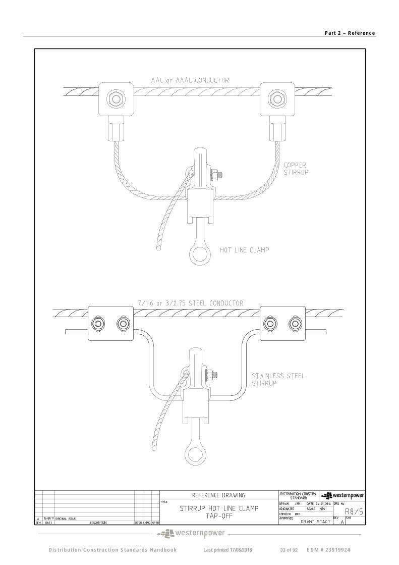
R08-5 A Stirrup Hot Line Clamp Tap - off
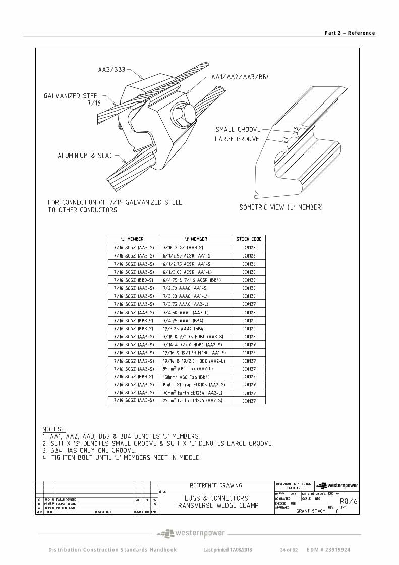
R08-6 B Lugs & Connectors – Transverse Wedge Clamp
R08-7 B Full Tension Compression Splices for Bare AAC/AAAC, Copper & Steel Conductors
R08-8 A Non Tension Compression Lugs and Sleeves
D is t r i bu t i on Cons t ruc t ion S tanda rds Handbook Last printed 17/08/2018 2 of 92 EDM # 23919924
Pa r t 2 – Re f e r ence
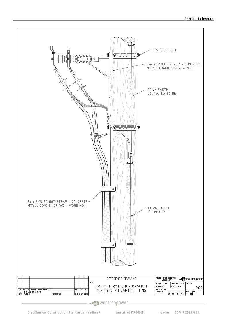
R09 D Cable Termination bracket, 1 ph & 3 ph Earth Fitting
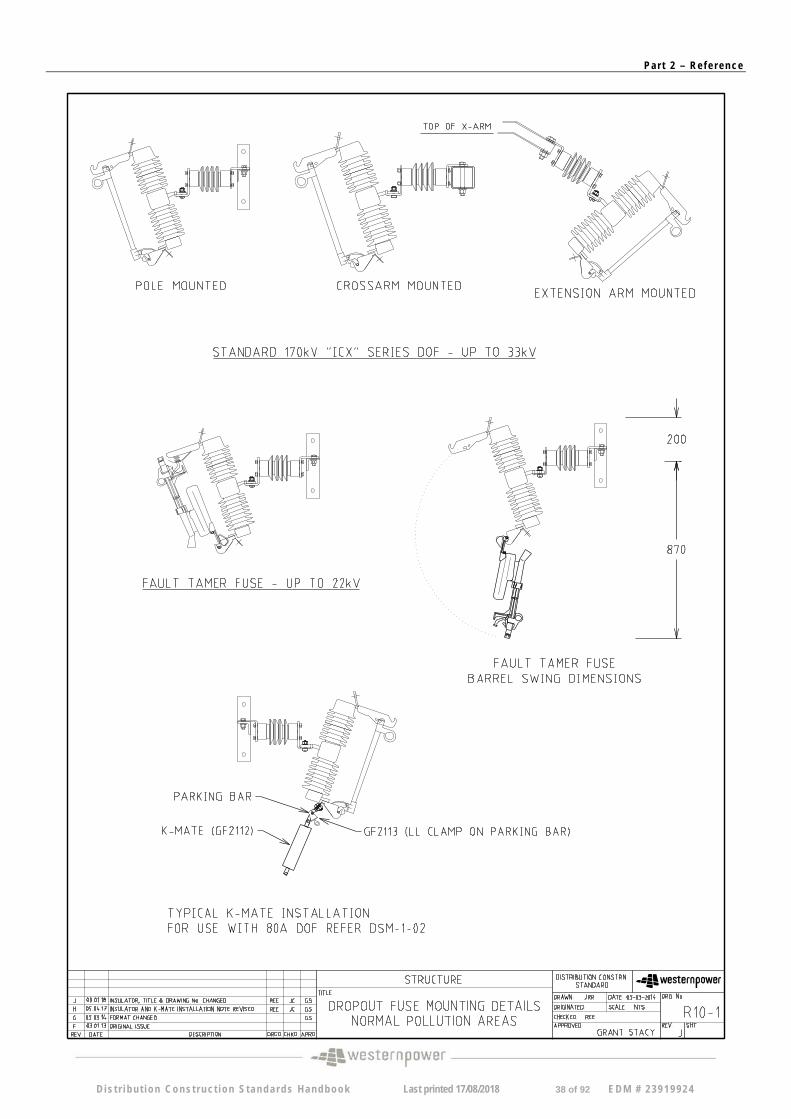
R10-1 J Dropout Fuse Mounting Details – Normal Pollution Area
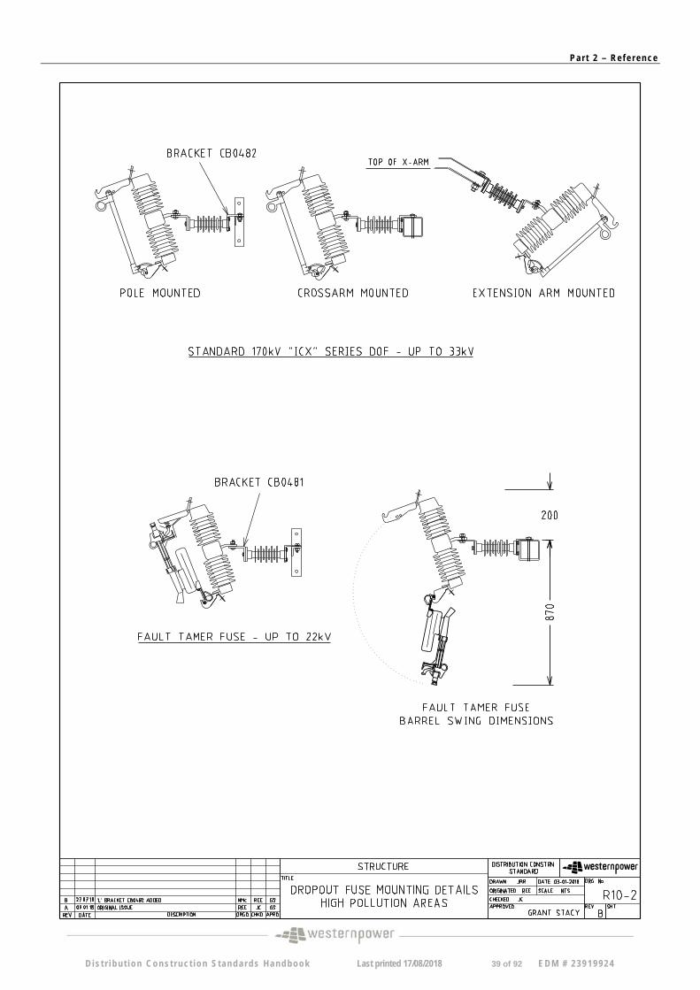
R10-2 B Dropout Fuse Mounting Details – High Pollution Area
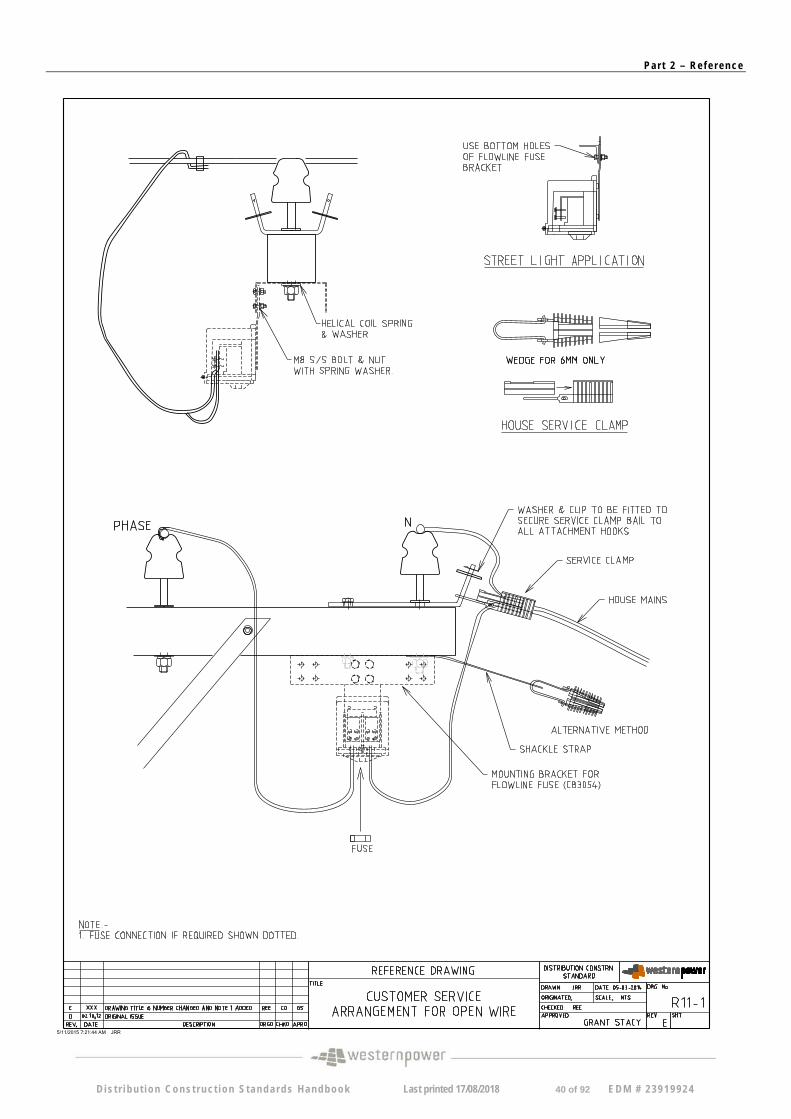
R11-1 E Customer service arrangement for open wire
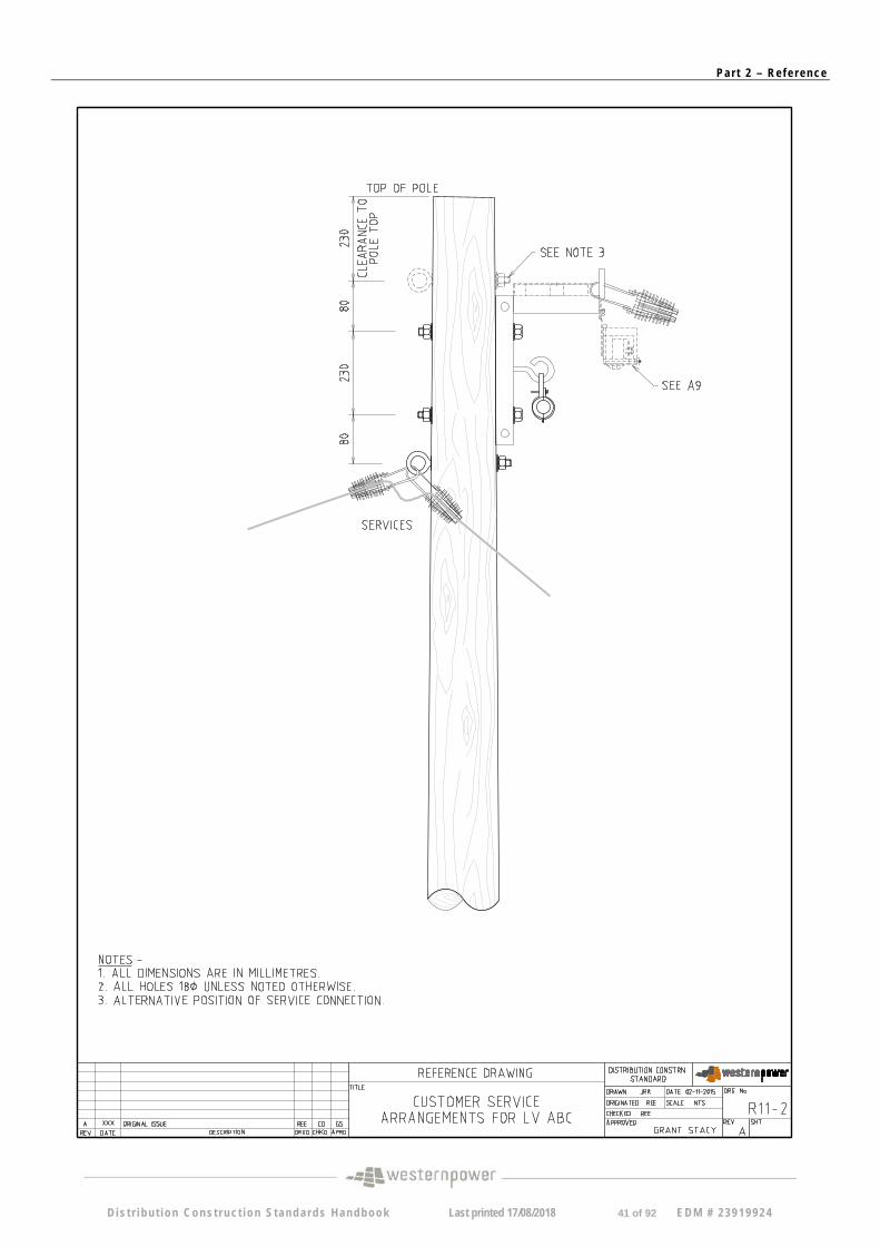
R11-2 A Customer service arrangement for LV ABC
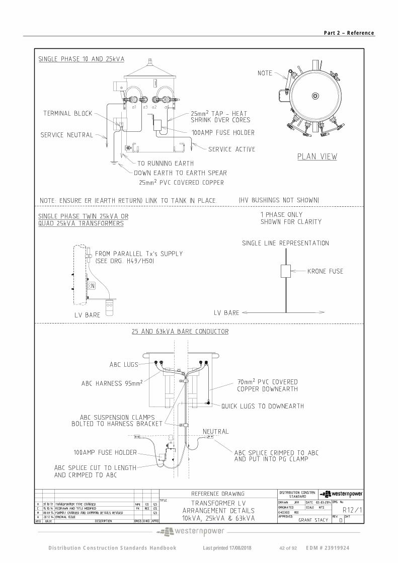
R12-1 D Transformer LV, Isolation Details 10Kva, 25Kva & 63Kva
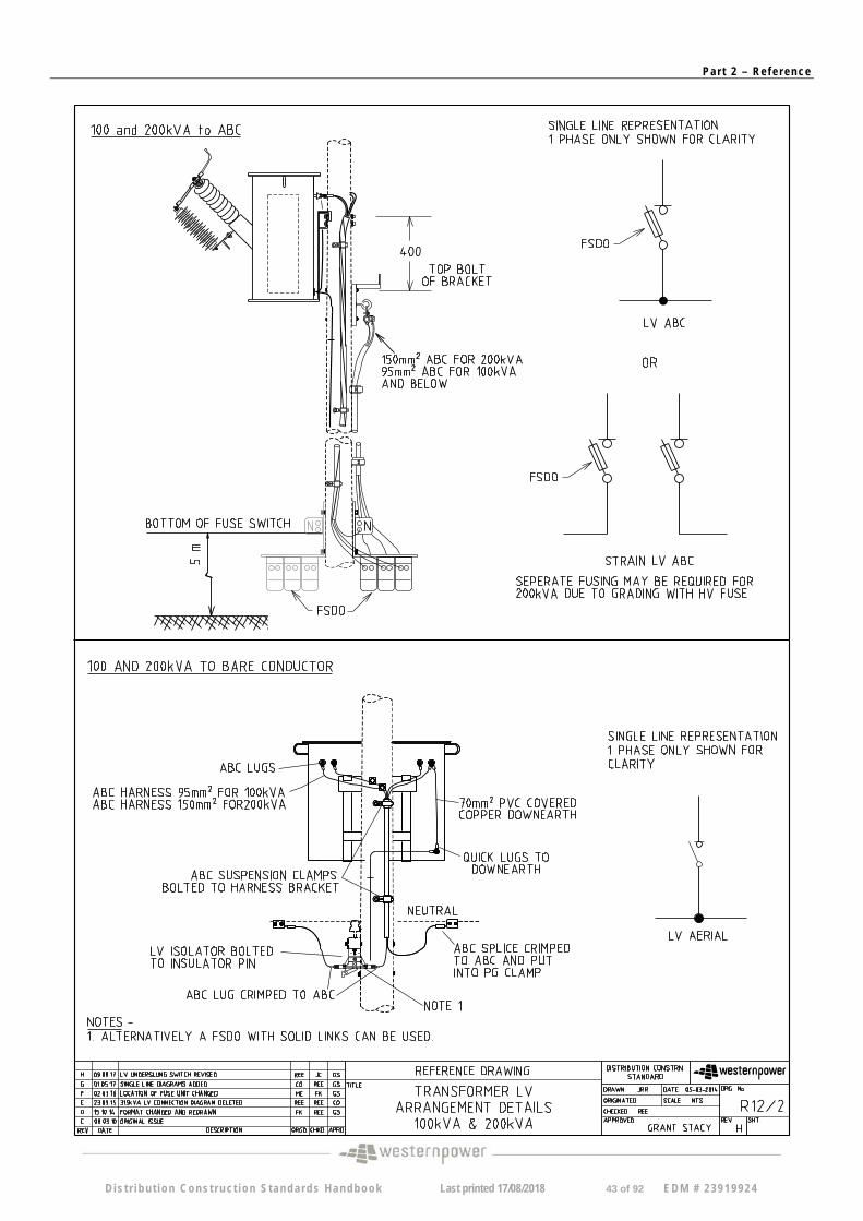
R12-2 H Transformer LV Arrangement Details 100kVA & 200kVA
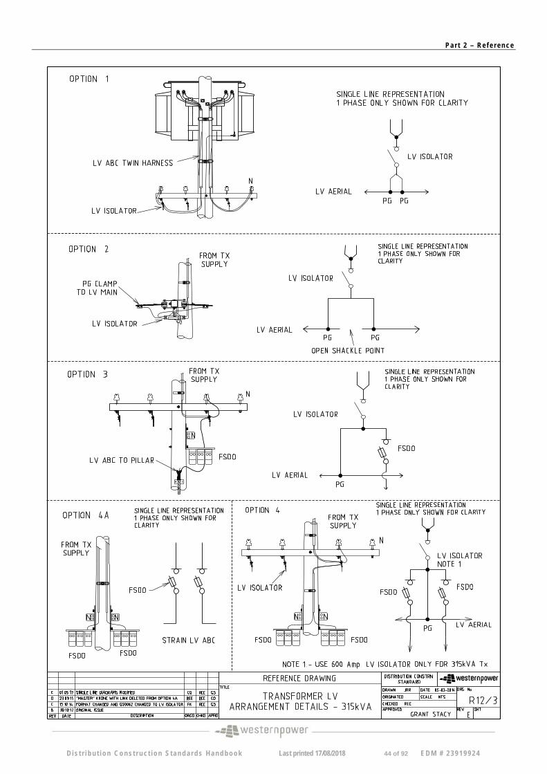
R12/3 E Transformer LV Arrangement Details 315kVA
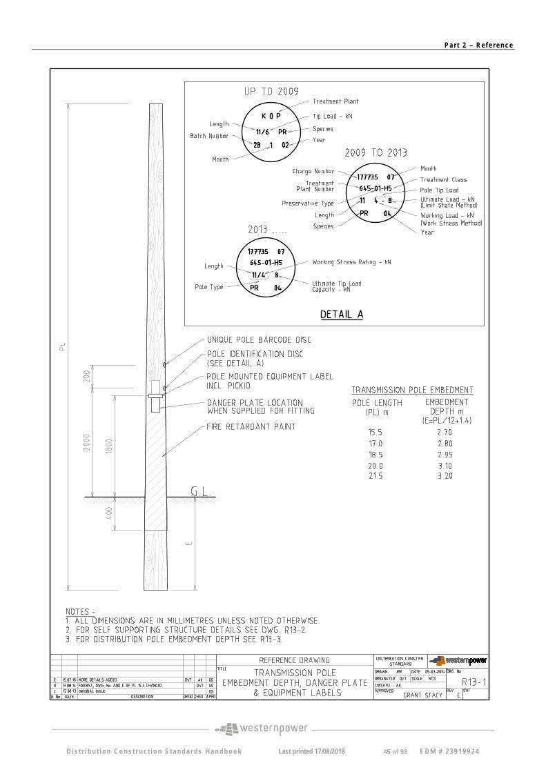
R13/1 E Pole Embedment Depth, Danger Plate
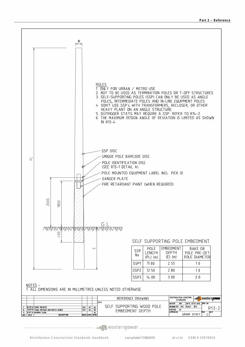
R13-2 C Self-Supporting Wood Pole Embedment Depth
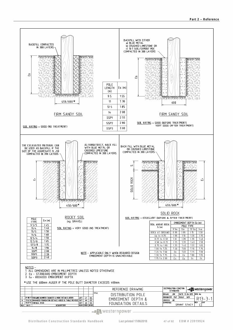
R13-3-1 C Distribution Pole Embedment Depth & Foundation Details (Sht. 1/2)
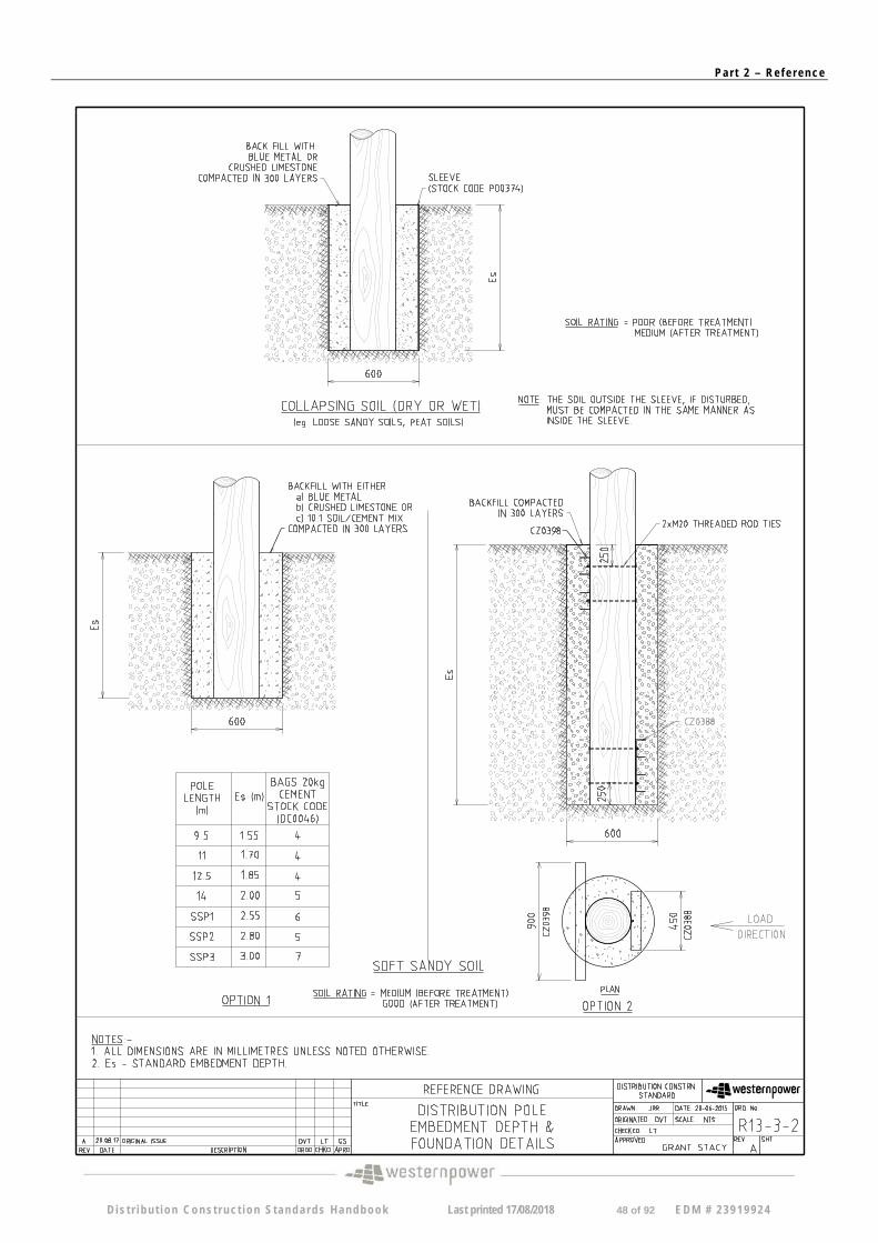
R13-3-2 A Distribution Pole Embedment Depth & Foundation Details (Sht. 2/2)
R13-4 B Wood Pole Design Angle of deviation for Urban applications
R13-5 A Wood Pole Design Angle of deviation for Rural applications
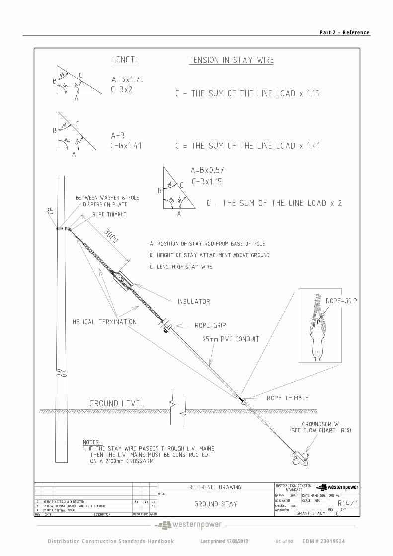
R14/1 C Ground Stay
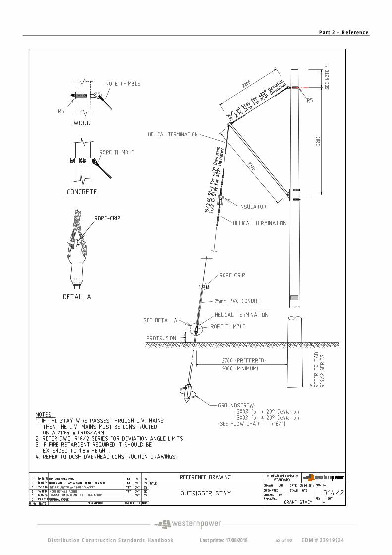
R14/2 H Outrigger Stay
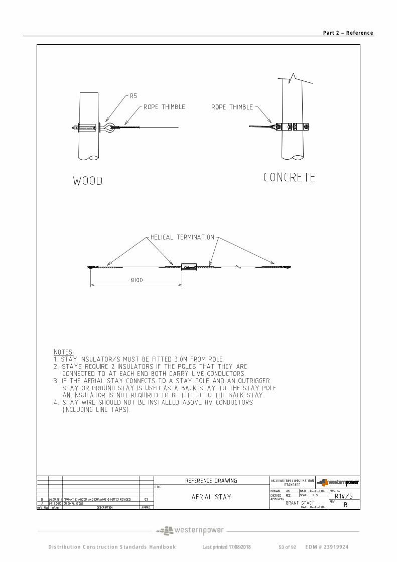
R14/5 B Aerial Stay
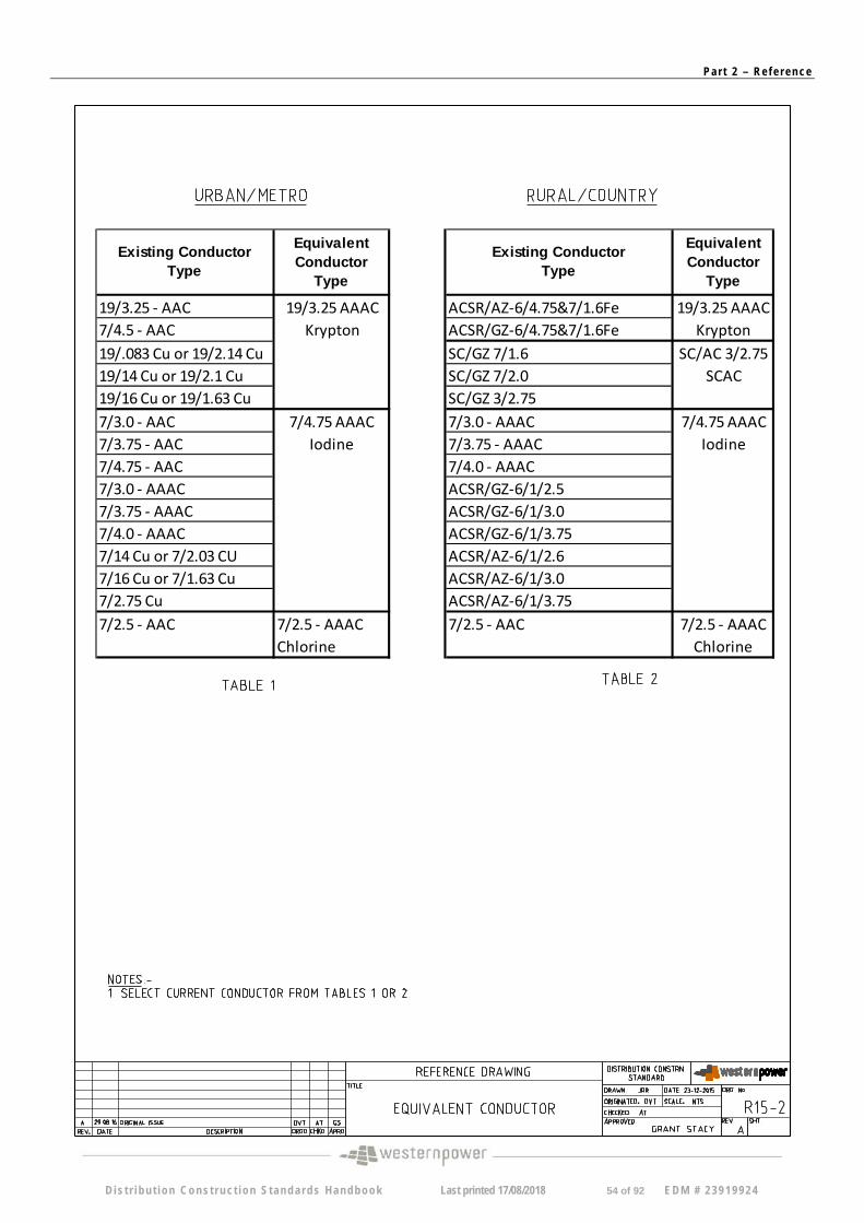
R15-2 A Equivalent Conductor
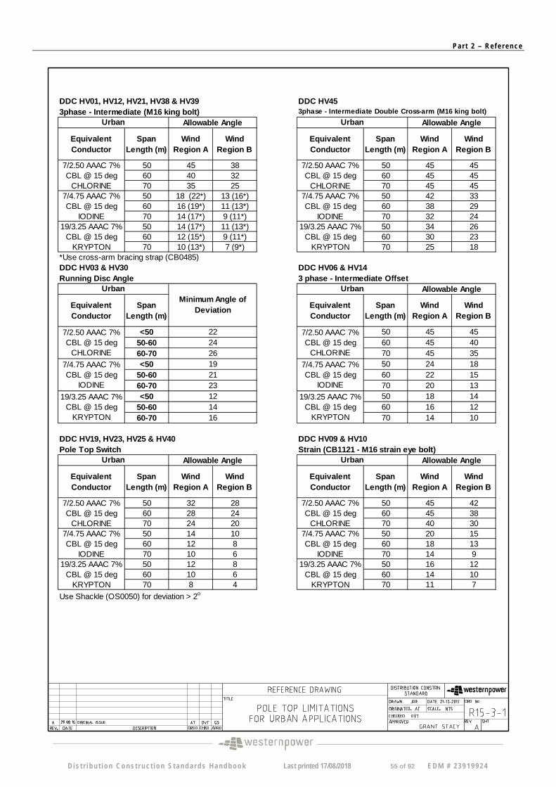
R15-3-1 A Pole Top Limitations for Urban Applications
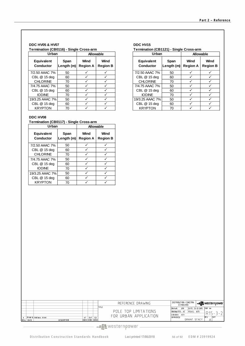
R15-3-2 A Pole Top Limitations for Urban Applications
R15-3-3 A Pole Top Limitations for Rural Applications
R15-3-4 A Pole Top Limitations for Rural Applications
R15-3-5 A Pole Top Limitations for Rural Applications
R15-3-6 A Pole Top Limitations for Rural Applications
R15-3-7 A Pole Top Limitations for Rural Applications
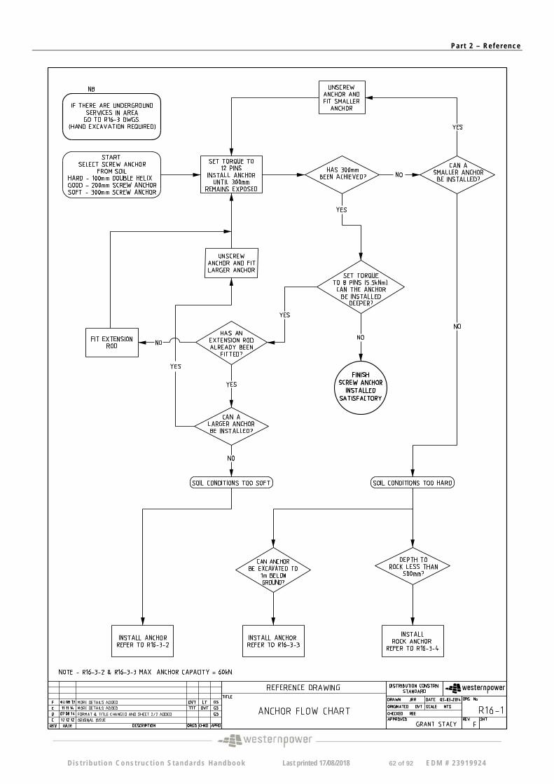
R16-1 F Anchor Flow Chart
R16/2 /1 E Screw Anchor Embedment Depth Dispensation Table for Distribution Poles – 9.5m
R16/2 /2 B Screw Anchor Embedment Depth Dispensation Table for Distribution Poles -11m (Sht 1/4)
R16/2 /3 B Screw Anchor Embedment Depth Dispensation Table for Distribution Poles – 11m (Sht 2/4
R16/2 /4 B Screw Anchor Embedment Depth Dispensation Table for Distribution Poles – 11m (Sht 3/4)
R16/2 /5 B Screw Anchor Embedment Depth Dispensation Table for Distribution Poles – 11m (Sht 4/4)
R16/2 /6 B Screw Anchor Embedment Depth Dispensation Table for Distribution Poles -12.5m (Sht. 1/4)
D is t r i bu t i on Cons t ruc t ion S tanda rds Handbook Last printed 17/08/2018 3 of 92 EDM # 23919924
Pa r t 2 – Re f e r ence
Screw Anchor Embedment Depth Dispensation Table for Distribution Poles – R16/2 /7 B
12.5m (Sht. 2/4)
Screw Anchor Embedment Depth Dispensation Table for Distribution Poles – R16/2 /8 B
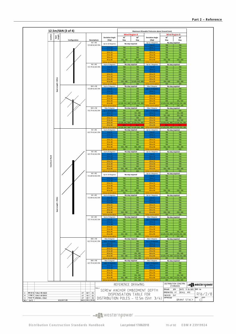
12.5m (Sht. 3/4)
Screw Anchor Embedment Depth Dispensation Table for Distribution Poles – R16/2 /9 B
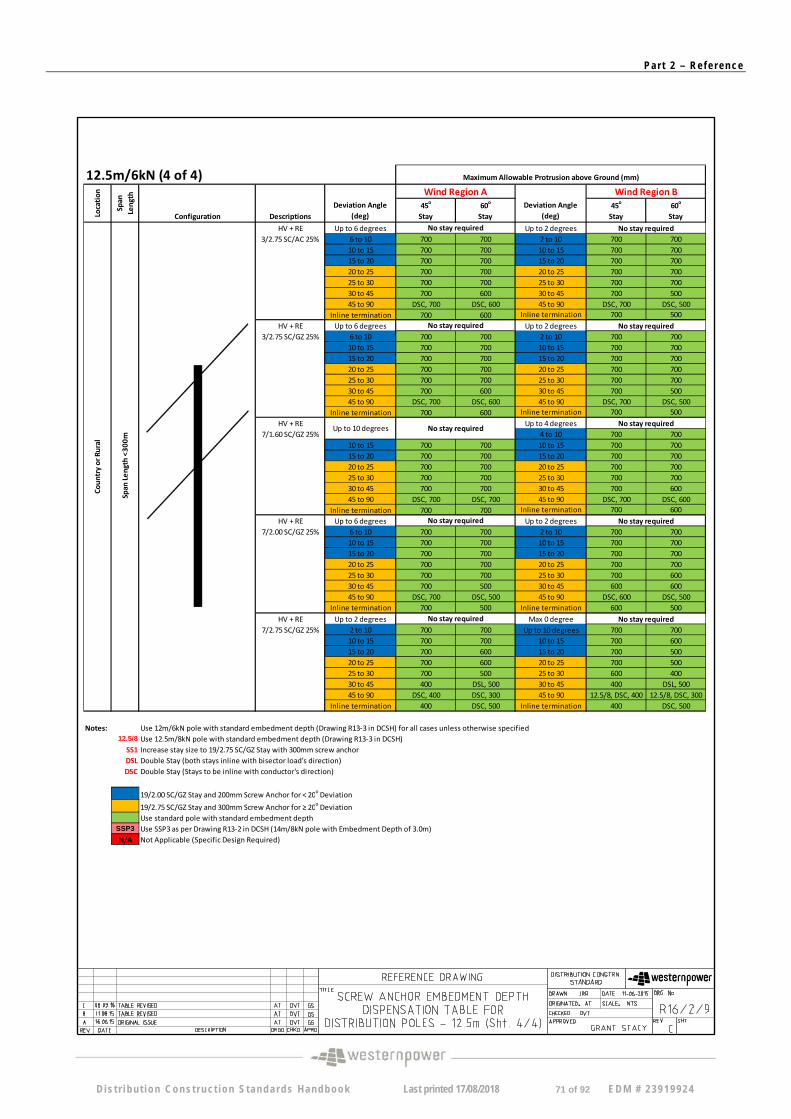
12.5m (Sht. 4/4)
R16-3-1 A Screw Anchor Installation for Medium to Hard Soil
R16-3-2 A Anchor Installation for Soft Soils
R16-3-3 B Anchor Installation for Hard Soil
R16-3-4 A Anchor Installation for Rock
R25 C Water Corporation – EVERBLU Collector Installation
R26-3 E Street Light Cut-out, Single Phase Supply for Double Insulated Equipment
R26-4 C Avenue Street Lights Luminaire Installation
R26-5 A Street Light Wiring Installation Standard (Part 1)
R26-6 B Street Light Wiring Installation Standard (Part 2)
R26-7 A Street Light Cut-out 1 Phase Supply for LED Class II Luminaires
R27 G Fusing Arrangement for Street Light Columns
R29 A 25kVA Padmount Tx LV Distribution Board 240V Terminal Block
R30 A 25kVA Padmount Tx LV Distribution Board 480V Terminal Block
R34-1 D LV Cable Live End Seal
R34-2 D HV Cable Live End Seal
R36-1 B Schneider (Nulec) Recloser Control Box Connection Detail
R36-2 A Schneider – ADVC2 Power Supply Control Box Connection Details
R37 A Nulec Recloser Solar Connection
R38 A Overhead Fault Indicator Solar Connection
R39 A Installer Identification Tag
R40 A Installation Of Above Ground Cable Marker
R41 A Customer Service Carryover Connection
D is t r i bu t i on Cons t ruc t ion S tanda rds Handbook Last printed 17/08/2018 4 of 92 EDM # 23919924
Pa r t 2 – Re f e r ence
General Notes
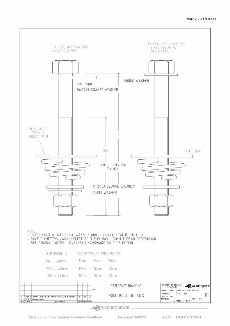
1. Overhead Hardware - Bolt Selection
All bolt holes must be drilled to size for the bolt being fitted as over size bolt holes allow excess plant/equipment movement which may result in the plant/equipment being damaged.
Pole bolt length selected to avoid excessive thread protrusion, maximum 100mm. Bolt packing (multiple washers/springs etc) must not be used as a permanent fixing.
Pole bolt excess thread may be flat trimmed and sharp edges must be removed to suit the fitting of washers and coil springs as per standard bolt selection. This is to prevent overlength bolts and/or sharp edges presenting a hazard to public and personnel safety (eg. pole top switch handle bolts). Cold galv or galmet should be applied to exposed metal.
2. Overhead Hardware – Sleeve/Splice Clearances
Fargo and crimp type compression sleeves must have a 100mm minimum clearance from all other line hardware such as insulators, conductor ties, armor rods, pg clamps and deadends etc.
3. Overhead Hardware – North Country Extreme Pollution Areas
In North Country (from Ledge Point to Kalbarri inclusively), all areas within 20 kilometres of the coast are considered to be in extremely corrosive environments. In such areas, grease and tape must be appropriately applied to all new lugs and connectors (as described in drawing R8/3) to prevent moisture ingress.
4. Overhead Hardware – Steel Strap (Band-It Strap) use on wood poles
Steel straps are not to be used on wood poles as the prime fixing method for equipment due to possible wood shrinkage causing the equipment to become loose and unstable. It may be used in conjunction with other fixing methods (eg. Bolts, coach screws, TEK screws, etc) but not as the sole support method.
D is t r i bu t i on Cons t ruc t ion S tanda rds Handbook Last printed 17/08/2018 5 of 92 EDM # 23919924
Pa r t 2 – Re f e r ence
D i s t r i bu t i on Cons t ruc t ion S tanda rds Handbook Last printed 17/08/2018 6 of 92 EDM # 23919924
Pa r t 2 – Re f e r ence
D i s t r i bu t i on Cons t ruc t ion S tanda rds Handbook Last printed 17/08/2018 7 of 92 EDM # 23919924
Pa r t 2 – Re f e r ence
D i s t r i bu t i on Cons t ruc t ion S tanda rds Handbook Last printed 17/08/2018 8 of 92 EDM # 23919924
Pa r t 2 – Re f e r ence
D i s t r i bu t i on Cons t ruc t ion S tanda rds Handbook Last printed 17/08/2018 9 of 92 EDM # 23919924
Pa r t 2 – Re f e r ence
D i s t r i bu t i on Cons t ruc t ion S tanda rds Handbook Last printed 17/08/2018 10 of 92 EDM # 2 3919924
Pa r t 2 – Re f e r ence
D i s t r i bu t i on Cons t ruc t ion S tanda rds Handbook Last printed 17/08/2018 11 of 92 EDM # 2 3919924
Pa r t 2 – Re f e r ence
D i s t r i bu t i on Cons t ruc t ion S tanda rds Handbook Last printed 17/08/2018 12 of 92 EDM # 2 3919924
Pa r t 2 – Re f e r ence
D i s t r i bu t i on Cons t ruc t ion S tanda rds Handbook Last printed 17/08/2018 13 of 92 EDM # 2 3919924
Pa r t 2 – Re f e r ence
D i s t r i bu t i on Cons t ruc t ion S tanda rds Handbook Last printed 17/08/2018 14 of 92 EDM # 2 3919924
Pa r t 2 – Re f e r ence
D i s t r i bu t i on Cons t ruc t ion S tanda rds Handbook Last printed 17/08/2018 15 of 92 EDM # 2 3919924
Pa r t 2 – Re f e r ence
D i s t r i bu t i on Cons t ruc t ion S tanda rds Handbook Last printed 17/08/2018 16 of 92 EDM # 2 3919924
Pa r t 2 – Re f e r ence
D i s t r i bu t i on Cons t ruc t ion S tanda rds Handbook Last printed 17/08/2018 17 of 92 EDM # 2 3919924
Pa r t 2 – Re f e r ence
D i s t r i bu t i on Cons t ruc t ion S tanda rds Handbook Last printed 17/08/2018 18 of 92 EDM # 2 3919924
Pa r t 2 – Re f e r ence
D i s t r i bu t i on Cons t ruc t ion S tanda rds Handbook Last printed 17/08/2018 19 of 92 EDM # 2 3919924
Pa r t 2 – Re f e r ence
D i s t r i bu t i on Cons t ruc t ion S tanda rds Handbook Last printed 17/08/2018 20 of 92 EDM # 2 3919924
Pa r t 2 – Re f e r ence
D i s t r i bu t i on Cons t ruc t ion S tanda rds Handbook Last printed 17/08/2018 21 of 92 EDM # 2 3919924
Pa r t 2 – Re f e r ence
D i s t r i bu t i on Cons t ruc t ion S tanda rds Handbook Last printed 17/08/2018 22 of 92 EDM # 2 3919924
Pa r t 2 – Re f e r ence
D i s t r i bu t i on Cons t ruc t ion S tanda rds Handbook Last printed 17/08/2018 23 of 92 EDM # 2 3919924
Pa r t 2 – Re f e r ence
D i s t r i bu t i on Cons t ruc t ion S tanda rds Handbook Last printed 17/08/2018 24 of 92 EDM # 2 3919924
Pa r t 2 – Re f e r ence
D i s t r i bu t i on Cons t ruc t ion S tanda rds Handbook Last printed 17/08/2018 25 of 92 EDM # 2 3919924
Pa r t 2 – Re f e r ence
D i s t r i bu t i on Cons t ruc t ion S tanda rds Handbook Last printed 17/08/2018 26 of 92 EDM # 2 3919924
Pa r t 2 – Re f e r ence
D i s t r i bu t i on Cons t ruc t ion S tanda rds Handbook Last printed 17/08/2018 27 of 92 EDM # 2 3919924
Pa r t 2 – Re f e r ence
D i s t r i bu t i on Cons t ruc t ion S tanda rds Handbook Last printed 17/08/2018 28 of 92 EDM # 2 3919924
Pa r t 2 – Re f e r ence
D i s t r i bu t i on Cons t ruc t ion S tanda rds Handbook Last printed 17/08/2018 29 of 92 EDM # 2 3919924
Pa r t 2 – Re f e r ence
D i s t r i bu t i on Cons t ruc t ion S tanda rds Handbook Last printed 17/08/2018 30 of 92 EDM # 2 3919924
Pa r t 2 – Re f e r ence
D i s t r i bu t i on Cons t ruc t ion S tanda rds Handbook Last printed 17/08/2018 31 of 92 EDM # 2 3919924
Pa r t 2 – Re f e r ence
D i s t r i bu t i on Cons t ruc t ion S tanda rds Handbook Last printed 17/08/2018 32 of 92 EDM # 2 3919924
Pa r t 2 – Re f e r ence
D i s t r i bu t i on Cons t ruc t ion S tanda rds Handbook Last printed 17/08/2018 33 of 92 EDM # 2 3919924
Pa r t 2 – Re f e r ence
D i s t r i bu t i on Cons t ruc t ion S tanda rds Handbook Last printed 17/08/2018 34 of 92 EDM # 2 3919924
Pa r t 2 – Re f e r ence
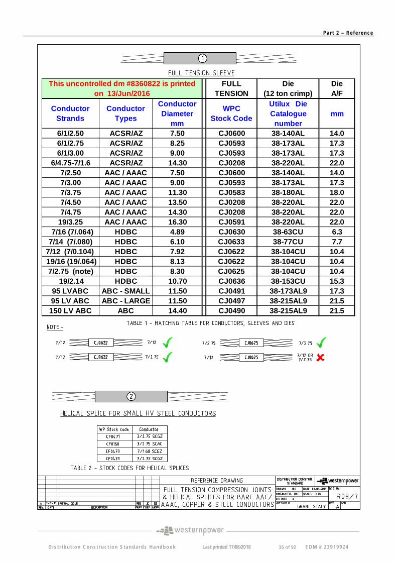
FULL TENSION
Die (12 ton crimp)
Die A/F
Conductor Strands
Conductor Types
Conductor Diameter
mm
WPC Stock Code
Utilux Die Catalogue
number mm
6/1/2.50 ACSR/AZ 7.50 CJ0600 38-140AL 14.0 6/1/2.75 ACSR/AZ 8.25 CJ0593 38-173AL 17.3 6/1/3.00 ACSR/AZ 9.00 CJ0593 38-173AL 17.3
6/4.75-7/1.6 ACSR/AZ 14.30 CJ0208 38-220AL 22.0 7/2.50 AAC / AAAC 7.50 CJ0600 38-140AL 14.0 7/3.00 AAC / AAAC 9.00 CJ0593 38-173AL 17.3 7/3.75 AAC / AAAC 11.30 CJ0583 38-180AL 18.0 7/4.50 AAC / AAAC 13.50 CJ0208 38-220AL 22.0 7/4.75 AAC / AAAC 14.30 CJ0208 38-220AL 22.0
19/3.25 AAC / AAAC 16.30 CJ0591 38-220AL 22.0 7/16 (7/.064) HDBC 4.89 CJ0630 38-63CU 6.3 7/14 (7/.080) HDBC 6.10 CJ0633 38-77CU 7.7
7/12 (7/0.104) HDBC 7.92 CJ0622 38-104CU 10.4 19/16 (19/.064) HDBC 8.13 CJ0622 38-104CU 10.4 7/2.75 (note) HDBC 8.30 CJ0625 38-104CU 10.4
19/2.14 HDBC 10.70 CJ0636 38-153CU 15.3 95 LVABC ABC - SMALL 11.50 CJ0491 38-173AL9 17.3 95 LV ABC ABC - LARGE 11.50 CJ0497 38-215AL9 21.5 150 LV ABC ABC 14.40 CJ0490 38-215AL9 21.5
This uncontrolled dm #8360822 is printed on 13/Jun/2016
D is t r i bu t i on Cons t ruc t ion S tanda rds Handbook Last printed 17/08/2018 35 of 92 EDM # 2 3919924
Pa r t 2 – Re f e r ence
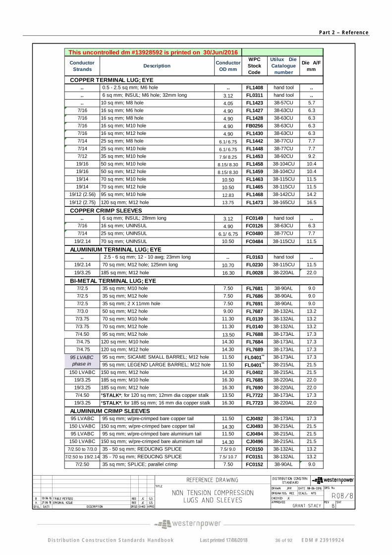
Conductor Strands
Description Conductor
OD mm
WPC Stock Code
Utilux Die Catalogue
number
Die A/F mm
.. 0.5 - 2.5 sq mm; M6 hole .. FL1408 hand tool ..
.. 6 sq mm; INSUL; M6 hole; 32mm long 3.12 FL0311 hand tool ..
.. 10 sq mm; M8 hole 4.05 FL1423 38-57CU 5.7
7/16 16 sq mm; M6 hole 4.90 FL1427 38-63CU 6.3
7/16 16 sq mm; M8 hole 4.90 FL1428 38-63CU 6.3
7/16 16 sq mm; M10 hole 4.90 FB0256 38-63CU 6.3
7/16 16 sq mm; M12 hole 4.90 FL1430 38-63CU 6.3
7/14 25 sq mm; M8 hole 6.1/ 6.75 FL1442 38-77CU 7.7
7/14 25 sq mm; M10 hole 6.1/ 6.75 FL1448 38-77CU 7.7
7/12 35 sq mm; M10 hole 7.9/ 8.25 FL1453 38-92CU 9.2
19/16 50 sq mm; M10 hole 8.15/ 8.30 FL1458 38-104CU 10.4
19/16 50 sq mm; M12 hole 8.15/ 8.30 FL1459 38-104CU 10.4
19/14 70 sq mm; M10 hole 10.50 FL1463 38-115CU 11.5
19/14 70 sq mm; M12 hole 10.50 FL1465 38-115CU 11.5
19/12 (2.56) 95 sq mm; M10 hole 12.83 FL1468 38-142CU 14.2
19/12 (2.75) 120 sq mm; M12 hole 13.75 FL1473 38-165CU 16.5
.. 6 sq mm; INSUL; 28mm long 3.12 FC0149 hand tool ..
7/16 16 sq mm; UNINSUL 4.90 FC0126 38-63CU 6.3
7/14 25 sq mm; UNINSUL 6.1/ 6.75 FC0480 38-77CU 7.7
19/2.14 70 sq mm; UNINSUL 10.50 FC0484 38-115CU 11.5
ALUMINIUM TERMINAL LUG; EYE .. 2.5 - 6 sq mm; 12 - 10 awg; 23mm long .. FL0163 hand tool ..
19/2.14 70 sq mm; M12 hole; 125mm long 10.70 FL0230 38-115CU 11.5
19/3.25 185 sq mm; M12 hole 16.30 FL0028 38-220AL 22.0
7/2.5 35 sq mm; M10 hole 7.50 FL7681 38-90AL 9.0
7/2.5 35 sq mm; M12 hole 7.50 FL7686 38-90AL 9.0
7/2.5 35 sq mm; 2 X 11mm hole 7.50 FL7691 38-90AL 9.0
7/3.0 50 sq mm; M12 hole 9.00 FL7687 38-132AL 13.2
7/3.75 70 sq mm; M10 hole 11.30 FL0139 38-132AL 13.2
7/3.75 70 sq mm; M12 hole 11.30 FL0140 38-132AL 13.2
7/4.50 95 sq mm; M12 hole 13.50 FL7688 38-173AL 17.3
7/4.75 120 sq mm; M10 hole 14.30 FL7684 38-173AL 17.3
7/4.75 120 sq mm; M12 hole 14.30 FL7689 38-173AL 17.3
95 sq mm; SICAME SMALL BARREL; M12 hole 11.50 FL0401** 38-173AL 17.3
95 sq mm; LEGEND LARGE BARREL; M12 hole 11.50 FL0401** 38-215AL 21.5
150 LVABC 150 sq mm; M12 hole 14.30 FL0402 38-215AL 21.5
19/3.25 185 sq mm; M10 hole 16.30 FL7685 38-220AL 22.0
19/3.25 185 sq mm; M12 hole 16.30 FL7690 38-220AL 22.0
7/4.50 *STALK*; for 120 sq mm; 12mm dia copper stalk 13.50 FL7722 38-173AL 17.3
19/3.25 *STALK*; for 185 sq mm; 16 mm dia copper stalk 16.30 FL7723 38-220AL 22.0
95 LVABC 95 sq mm; w/pre-crimped bare copper tail 11.50 CJ0492 38-173AL 17.3
150 LVABC 150 sq mm; w/pre-crimped bare copper tail 14.30 CJ0493 38-215AL 21.5
95 LVABC 95 sq mm; w/pre-crimped bare aluminium tail 11.50 CJ0494 38-215AL 21.5
150 LVABC 150 sq mm; w/pre-crimped bare aluminium tail 14.30 CJ0496 38-215AL 21.5
7/2.50 to 7/3.0 35 - 50 sq mm; REDUCING SPLICE 7.5/ 9.0 FC0150 38-132AL 13.2
7/2.50 to 19/2.14 35 - 70 sq mm; REDUCING SPLICE 7.5/ 10.7 FC0151 38-132AL 13.2
7/2.50 35 sq mm; SPLICE; parallel crimp 7.50 FC0152 38-90AL 9.0
ALUMINIUM CRIMP SLEEVES
This uncontrolled dm #13928592 is printed on 30/Jun/2016
COPPER TERMINAL LUG; EYE
COPPER CRIMP SLEEVES
BI-METAL TERMINAL LUG; EYE
95 LVABC phase in
D is t r i bu t i on Cons t ruc t ion S tanda rds Handbook Last printed 17/08/2018 36 of 92 EDM # 2 3919924
Pa r t 2 – Re f e r ence
D i s t r i bu t i on Cons t ruc t ion S tanda rds Handbook Last printed 17/08/2018 37 of 92 EDM # 2 3919924
Pa r t 2 – Re f e r ence
D i s t r i bu t i on Cons t ruc t ion S tanda rds Handbook Last printed 17/08/2018 38 of 92 EDM # 2 3919924
Pa r t 2 – Re f e r ence
D i s t r i bu t i on Cons t ruc t ion S tanda rds Handbook Last printed 17/08/2018 39 of 92 EDM # 2 3919924
Pa r t 2 – Re f e r ence
5/11/2015 7:21:44 AM JRR
D is t r i bu t i on Cons t ruc t ion S tanda rds Handbook Last printed 17/08/2018 40 of 92 EDM # 2 3919924
Pa r t 2 – Re f e r ence
D i s t r i bu t i on Cons t ruc t ion S tanda rds Handbook Last printed 17/08/2018 41 of 92 EDM # 2 3919924
Pa r t 2 – Re f e r ence
D i s t r i bu t i on Cons t ruc t ion S tanda rds Handbook Last printed 17/08/2018 42 of 92 EDM # 2 3919924
Pa r t 2 – Re f e r ence
D i s t r i bu t i on Cons t ruc t ion S tanda rds Handbook Last printed 17/08/2018 43 of 92 EDM # 2 3919924
Pa r t 2 – Re f e r ence
D i s t r i bu t i on Cons t ruc t ion S tanda rds Handbook Last printed 17/08/2018 44 of 92 EDM # 2 3919924
Pa r t 2 – Re f e r ence
D i s t r i bu t i on Cons t ruc t ion S tanda rds Handbook Last printed 17/08/2018 45 of 92 EDM # 2 3919924
Pa r t 2 – Re f e r ence
D i s t r i bu t i on Cons t ruc t ion S tanda rds Handbook Last printed 17/08/2018 46 of 92 EDM # 2 3919924
Pa r t 2 – Re f e r ence
D i s t r i bu t i on Cons t ruc t ion S tanda rds Handbook Last printed 17/08/2018 47 of 92 EDM # 2 3919924
Pa r t 2 – Re f e r ence
D i s t r i bu t i on Cons t ruc t ion S tanda rds Handbook Last printed 17/08/2018 48 of 92 EDM # 2 3919924
Pa r t 2 – Re f e r ence
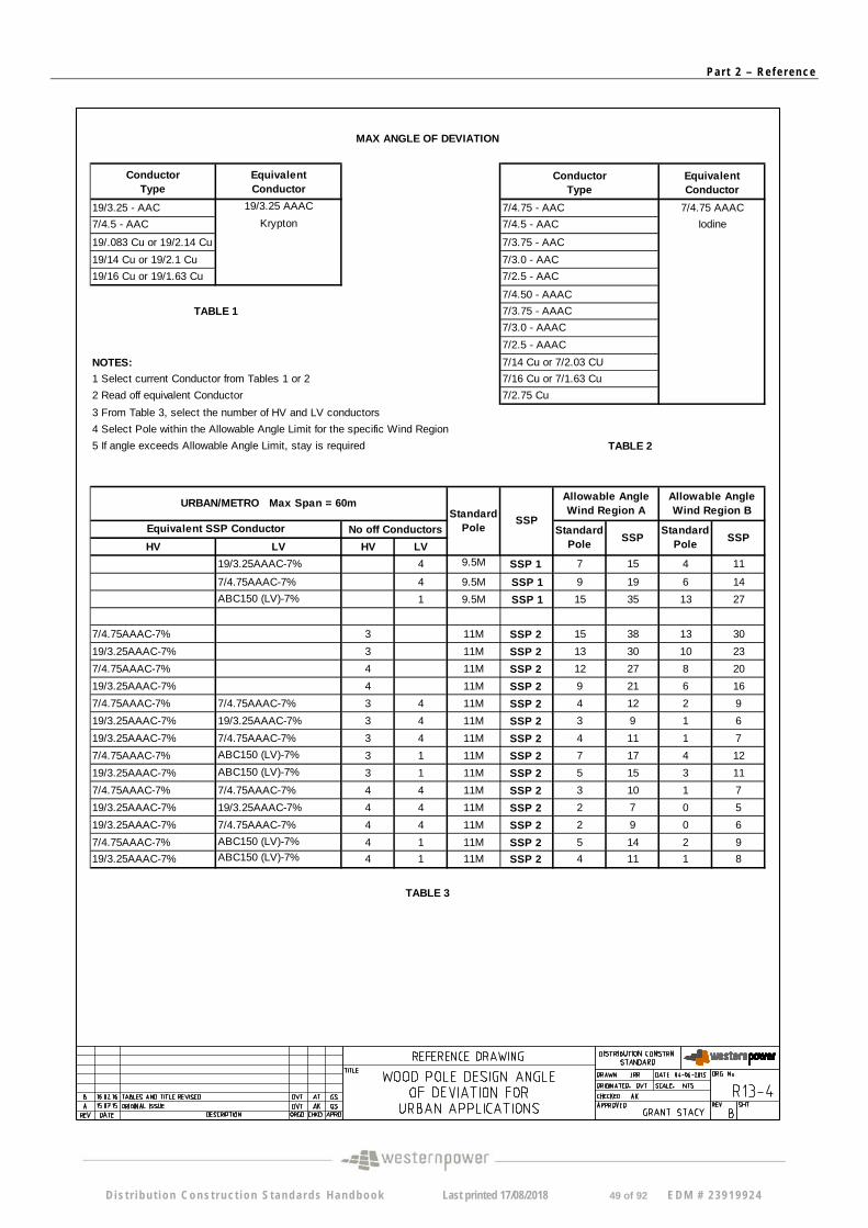
MAX ANGLE OF DEVIATION
Conductor Equivalent Type Conductor
19/3.25 - AAC 19/3.25 AAAC
Krypton 7/4.5 - AAC
19/.083 Cu or 19/2.14 Cu
19/14 Cu or 19/2.1 Cu
19/16 Cu or 19/1.63 Cu
Conductor Equivalent Type Conductor
7/4.75 - AAC 7/4.75 AAAC
Iodine 7/4.5 - AAC
7/3.75 - AAC
7/3.0 - AAC
7/2.5 - AAC
7/4.50 - AAAC
7/3.75 - AAAC
7/3.0 - AAAC
7/2.5 - AAAC
7/14 Cu or 7/2.03 CU
7/16 Cu or 7/1.63 Cu
7/2.75 Cu
TABLE 1
NOTES:
1 Select current Conductor from Tables 1 or 2
2 Read off equivalent Conductor
3 From Table 3, select the number of HV and LV conductors
4 Select Pole within the Allowable Angle Limit for the specific Wind Region
5 If angle exceeds Allowable Angle Limit, stay is required TABLE 2
URBAN/METRO Max Span = 60m
Equivalent SSP Conductor No off Conductors
HV LV HV LV
19/3.25AAAC-7% 4
7/4.75AAAC-7% 4
ABC150 (LV)-7% 1
7/4.75AAAC-7% 3
19/3.25AAAC-7% 3
7/4.75AAAC-7% 4
19/3.25AAAC-7% 4
7/4.75AAAC-7% 7/4.75AAAC-7% 3 4
19/3.25AAAC-7% 19/3.25AAAC-7% 3 4
19/3.25AAAC-7% 7/4.75AAAC-7% 3 4
7/4.75AAAC-7% ABC150 (LV)-7% 3 1
19/3.25AAAC-7% ABC150 (LV)-7% 3 1
7/4.75AAAC-7% 7/4.75AAAC-7% 4 4
19/3.25AAAC-7% 19/3.25AAAC-7% 4 4
19/3.25AAAC-7% 7/4.75AAAC-7% 4 4
7/4.75AAAC-7% ABC150 (LV)-7% 4 1
19/3.25AAAC-7% ABC150 (LV)-7% 4 1
Standard Pole
9.5M
9.5M
9.5M
11M
11M
11M
11M
11M
11M
11M
11M
11M
11M
11M
11M
11M
11M
SSP
SSP 1
SSP 1
SSP 1
SSP 2
SSP 2
SSP 2
SSP 2
SSP 2
SSP 2
SSP 2
SSP 2
SSP 2
SSP 2
SSP 2
SSP 2
SSP 2
SSP 2
Allowable Angle Wind Region A
Standard SSP
Pole
7 15
9 19
15 35
15 38
13 30
12 27
9 21
4 12
3 9
4 11
7 17
5 15
3 10
2 7
2 9
5 14
4 11
Allowable Angle Wind Region B
Standard SSP
Pole
4 11
6 14
13 27
13 30
10 23
8 20
6 16
2 9
1 6
1 7
4 12
3 11
1 7
0 5
0 6
2 9
1 8
TABLE 3
D is t r i bu t i on Cons t ruc t ion S tanda rds Handbook Last printed 17/08/2018 49 of 92 EDM # 2 3919924
Pa r t 2 – Re f e r ence
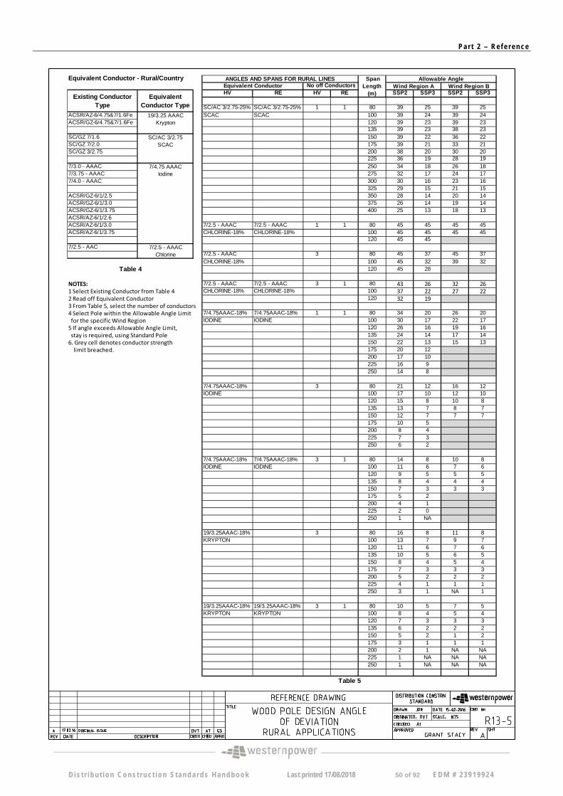
Equivalent Conductor - Rural/Country
HV RE HV RE SSP2 SSP3 SSP2 SSP3
SC/AC 3/2.75-25% SC/AC 3/2.75-25% 1 1 80 39 25 39 25 ACSR/AZ-6/4.75&7/1.6Fe 19/3.25 AAAC SCAC SCAC 100 39 24 39 24 ACSR/GZ-6/4.75&7/1.6Fe Krypton 120 39 23 39 23
135 39 23 38 23 SC/GZ 7/1.6 SC/AC 3/2.75 150 39 22 36 22 SC/GZ 7/2.0 SCAC 175 39 21 33 21 SC/GZ 3/2.75 200 38 20 30 20
225 36 19 28 19 7/3.0 - AAAC 7/4.75 AAAC 250 34 18 26 18 7/3.75 - AAAC Iodine 275 32 17 24 17 7/4.0 - AAAC 300 30 16 23 16
325 29 15 21 15 ACSR/GZ-6/1/2.5 350 28 14 20 14 ACSR/GZ-6/1/3.0 375 26 14 19 14
400 25 13 18 13
7/2.5 - AAAC 7/2.5 - AAAC 1 1 80 45 45 45 45 CHLORINE-18% CHLORINE-18% 100 45 45 45 45
120 45 45
7/2.5 - AAAC 3 80 45 37 45 37 CHLORINE-18% 100 45 32 39 32
120 45 28
7/2.5 - AAAC 7/2.5 - AAAC 3 1 80 43 26 32 26 CHLORINE-18% CHLORINE-18% 100 37 22 27 22
120 32 19
7/4.75AAAC-18% 7/4.75AAAC-18% 1 1 80 34 20 26 20 IODINE IODINE 100 30 17 22 17
120 26 16 19 16 135 24 14 17 14 150 22 13 15 13175 20 12 200 17 10 225 16 9 250 14 8
7/4.75AAAC-18% 3 80 21 12 16 12 IODINE 100 17 10 12 10
120 15 8 10 8 135 13 7 8 7 150 12 7 7 7 175 10 5 200 8 4 225 7 3 250 6 2
7/4.75AAAC-18% 7/4.75AAAC-18% 3 1 80 14 8 10 8 IODINE IODINE 100 11 6 7 6
120 9 5 5 5 135 8 4 4 4 150 7 3 3 3 175 5 2 200 4 1 225 2 0 250 1 NA
19/3.25AAAC-18% 3 80 16 8 11 8 KRYPTON 100 13 7 9 7
120 11 6 7 6 135 10 5 6 5 150 8 4 5 4 175 7 3 3 3 200 5 2 2 2 225 4 1 1 1 250 3 1 NA 1
19/3.25AAAC-18% 19/3.25AAAC-18% 3 1 80 10 5 7 5 KRYPTON KRYPTON 100 8 4 5 4
120 7 3 3 3 135 6 2 2 2 150 5 2 1 2 175 3 1 1 1 200 2 1 NA NA 225 1 NA NA NA 250 1 NA NA NA
Allowable Angle Wind Region A Wind Region B
ANGLES AND SPANS FOR RURAL LINES No off ConductorsEquivalent Conductor
Span Length
(m)
ACSR/GZ-6/1/3.75 ACSR/AZ-6/1/2.6 ACSR/AZ-6/1/3.0 ACSR/AZ-6/1/3.75
7/2.5 - AAC 7/2.5 - AAAC Chlorine
NOTES: 1 Select Existing Conductor from Table 4 2 Read off Equivalent Conductor 3 From Table 5, select the number of conductors 4 Select Pole within the Allowable Angle Limit for the specific Wind Region 5 If angle exceeds Allowable Angle Limit, stay is required, using Standard Pole 6. Grey cell denotes conductor strength limit breached.
Table 5
Table 4
Existing Conductor Type
Equivalent Conductor Type
D is t r i bu t i on Cons t ruc t ion S tanda rds Handbook Last printed 17/08/2018 50 of 92 EDM # 2 3919924
Pa r t 2 – Re f e r ence
D i s t r i bu t i on Cons t ruc t ion S tanda rds Handbook Last printed 17/08/2018 51 of 92 EDM # 2 3919924
Pa r t 2 – Re f e r ence
D i s t r i bu t i on Cons t ruc t ion S tanda rds Handbook Last printed 17/08/2018 52 of 92 EDM # 2 3919924
Pa r t 2 – Re f e r ence
D i s t r i bu t i on Cons t ruc t ion S tanda rds Handbook Last printed 17/08/2018 53 of 92 EDM # 2 3919924
Pa r t 2 – Re f e r ence
Existing Conductor Type
Equivalent Conductor
Type
Existing Conductor Type
Equivalent Conductor
Type
19/3.25 ‐ AAC 19/3.25 AAAC ACSR/AZ‐6/4.75&7/1.6Fe 19/3.25 AAAC 7/4.5 ‐ AAC Krypton ACSR/GZ‐6/4.75&7/1.6Fe Krypton
19/.083 Cu or 19/2.14 Cu SC/GZ 7/1.6 SC/AC 3/2.75 19/14 Cu or 19/2.1 Cu SC/GZ 7/2.0 SCAC 19/16 Cu or 19/1.63 Cu SC/GZ 3/2.75
7/3.0 ‐ AAC 7/4.75 AAAC 7/3.0 ‐ AAAC 7/4.75 AAAC 7/3.75 ‐ AAC Iodine 7/3.75 ‐ AAAC Iodine 7/4.75 ‐ AAC 7/4.0 ‐ AAAC 7/3.0 ‐ AAAC ACSR/GZ‐6/1/2.5 7/3.75 ‐ AAAC ACSR/GZ‐6/1/3.0 7/4.0 ‐ AAAC ACSR/GZ‐6/1/3.75 7/14 Cu or 7/2.03 CU ACSR/AZ‐6/1/2.6 7/16 Cu or 7/1.63 Cu ACSR/AZ‐6/1/3.0 7/2.75 Cu ACSR/AZ‐6/1/3.75
7/2.5 ‐ AAAC 7/2.5 ‐ AAAC Chlorine Chlorine
7/2.5 ‐ AAC 7/2.5 ‐ AAC
D is t r i bu t i on Cons t ruc t ion S tanda rds Handbook Last printed 17/08/2018 54 of 92 EDM # 2 3919924
Pa r t 2 – Re f e r ence
DDC HV01, HV12, HV21, HV38 & HV39 DDC HV45 3phase - Intermediate (M16 king bolt) 3phase - Intermediate Double Cross-arm (M16 king bolt)
Equivalent Conductor
Span Length (m)
Wind Region A
Wind Region B
Equivalent Conductor
Span Length (m)
Wind Region A
Wind Region B
50 45 38 50 45 45 60 40 32 60 45 45 70 35 25 70 45 45 50 18 (22*) 13 (16*) 50 42 33 60 16 (19*) 11 (13*) 60 38 29 70 14 (17*) 9 (11*) 70 32 24 50 14 (17*) 11 (13*) 50 34 26 60 12 (15*) 9 (11*) 60 30 23 70 10 (13*) 7 (9*) 70 25 18
*Use cross-arm bracing strap (CB0485) DDC HV03 & HV30 DDC HV06 & HV14 Running Disc Angle 3 phase - Intermediate Offset
Equivalent Conductor
Span Length (m)
Equivalent Conductor
Span Length (m)
Wind Region A
Wind Region B
<50 50 45 45 50-60 60 45 40 60-70 70 45 35 <50 50 24 18
50-60 60 22 15 60-70 70 20 13 <50 50 18 14
50-60 60 16 12 60-70 70 14 10
DDC HV19, HV23, HV25 & HV40 DDC HV09 & HV10 Pole Top Switch Strain (CB1121 - M16 strain eye bolt)
Equivalent Conductor
Span Length (m)
Wind Region A
Wind Region B
Equivalent Conductor
Span Length (m)
Wind Region A
Wind Region B
50 32 28 50 45 42 60 28 24 60 45 38 70 24 20 70 40 30 50 14 10 50 20 15 60 12 8 60 18 13 70 10 6 70 14 9 50 12 8 50 16 12 60 10 6 60 14 10 70 8 4 70 11 7
Use Shackle (OS0050) for deviation > 2o
7/4.75 AAAC 7% CBL @ 15 deg
IODINE 19/3.25 AAAC 7%
CBL @ 15 deg KRYPTON
19/3.25 AAAC 7% CBL @ 15 deg
KRYPTON
12 14 16
7/4.75 AAAC 7% CBL @ 15 deg
IODINE
26 19 21 23
Urban Allowable Angle
7/2.50 AAAC 7% CBL @ 15 deg
CHLORINE
Urban Allowable Angle
7/2.50 AAAC 7% CBL @ 15 deg
CHLORINE
Urban
19/3.25 AAAC 7% CBL @ 15 deg
KRYPTON
Urban
7/4.75 AAAC 7% CBL @ 15 deg
IODINE
19/3.25 AAAC 7% CBL @ 15 deg
KRYPTON
Minimum Angle of Deviation
22 24
7/2.50 AAAC 7% CBL @ 15 deg
CHLORINE
7/4.75 AAAC 7% CBL @ 15 deg
IODINE
19/3.25 AAAC 7% CBL @ 15 deg
KRYPTON
7/4.75 AAAC 7% CBL @ 15 deg
IODINE
Urban Allowable Angle
7/2.50 AAAC 7% CBL @ 15 deg
CHLORINE
19/3.25 AAAC 7% CBL @ 15 deg
KRYPTON
Allowable Angle
7/2.50 AAAC 7% CBL @ 15 deg
CHLORINE
Urban Allowable Angle
7/2.50 AAAC 7% CBL @ 15 deg
CHLORINE
7/4.75 AAAC 7% CBL @ 15 deg
IODINE
D is t r i bu t i on Cons t ruc t ion S tanda rds Handbook Last printed 17/08/2018 55 of 92 EDM # 2 3919924
Pa r t 2 – Re f e r ence
DDC HV05 & HV07 DDC HV15 Termination (CB0116) - Single Cross-arm Termination (CB1121) - Single Cross-arm
Equivalent Conductor
Span Length (m)
Wind Region A
Wind Region B
Equivalent Conductor
Span Length (m)
Wind Region A
Wind Region B
50 50 60 60 70 70 50 50 60 60 70 70 50 50 60 60 70 70
DDC HV08 Termination (CB0117) - Single Cross-arm
Equivalent Conductor
Span Length (m)
Wind Region A
Wind Region B
50 60 70 50 60 70 50 60
70
Allowable
7/2.50 AAAC 7% CBL @ 15 deg
CHLORINE
Urban
7/4.75 AAAC 7% CBL @ 15 deg
IODINE
19/3.25 AAAC 7% CBL @ 15 deg
KRYPTON
Urban Allowable
7/2.50 AAAC 7% CBL @ 15 deg
CHLORINE 7/4.75 AAAC 7% CBL @ 15 deg
IODINE 19/3.25 AAAC 7%
CBL @ 15 deg KRYPTON
Urban Allowable
7/2.50 AAAC 7% CBL @ 15 deg
CHLORINE 7/4.75 AAAC 7% CBL @ 15 deg
IODINE 19/3.25 AAAC 7%
CBL @ 15 deg KRYPTON
D is t r i bu t i on Cons t ruc t ion S tanda rds Handbook Last printed 17/08/2018 56 of 92 EDM # 2 3919924
Pa r t 2 – Re f e r ence
DDC HV01, HV12, HV21, HV38 & HV39 DDC HV45 3phase - Intermediate (M16 king bolt) 3phase - Intermediate Double Cross-arm (M16 king bolt)
Equivalent Conductor
Span Length (m)
Wind Region A
Wind Region B
Equivalent Conductor
Span Length (m)
Wind Region A
Wind Region B
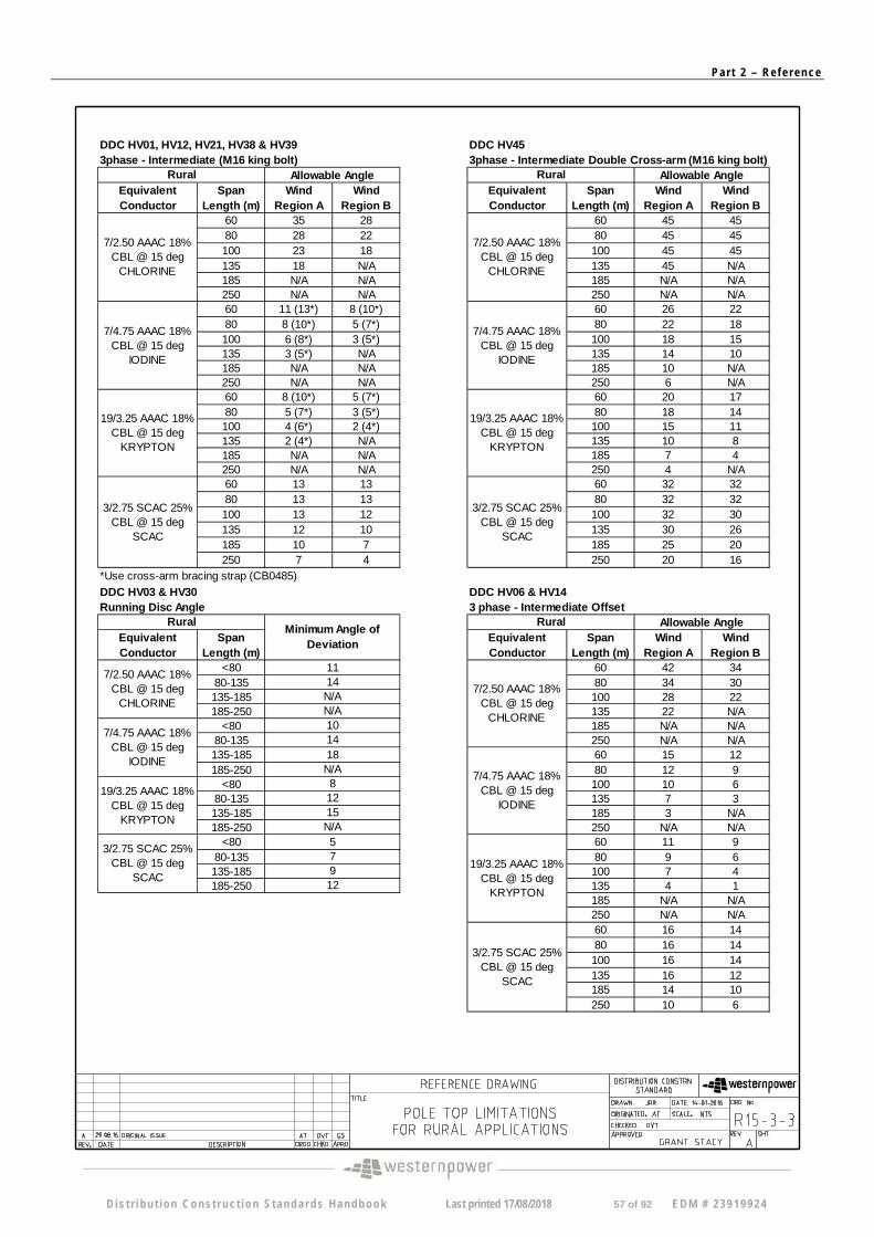
60 35 28 60 45 45 80 28 22 80 45 45 100 23 18 100 45 45 135 18 N/A 135 45 N/A 185 N/A N/A 185 N/A N/A 250 N/A N/A 250 N/A N/A 60 11 (13*) 8 (10*) 60 26 22 80 8 (10*) 5 (7*) 80 22 18 100 6 (8*) 3 (5*) 100 18 15 135 3 (5*) N/A 135 14 10 185 N/A N/A 185 10 N/A 250 N/A N/A 250 6 N/A 60 8 (10*) 5 (7*) 60 20 17 80 5 (7*) 3 (5*) 80 18 14 100 4 (6*) 2 (4*) 135 2 (4*) N/A 185 N/A N/A 250 N/A N/A 60 13 13 80 13 13 100 13 12 135 12 10 185 10 7 250 7 4
Equivalent Conductor
Span Length (m)
Equivalent Conductor
Span Length (m)
Wind Region A
Wind Region B
<80 60 42 34 80-135 80 34 30 135-185 100 28 22 185-250 135 22 N/A
<80 185 N/A N/A 80-135 250 N/A N/A 135-185 60 15 12 185-250 80 12 9
<80 100 10 6 80-135 135 7 3 135-185 185 3 N/A 185-250 250 N/A N/A
<80 60 11 9 80-135 80 9 6 135-185 100 7 4 185-250 135 4 1
185 N/A N/A 250 N/A N/A 60 16 14 80 16 14 100 16 14 135 16 12 185 14 10 250 10 6
Rural Allowable Angle
7/2.50 AAAC 18% CBL @ 15 deg
CHLORINE
7/4.75 AAAC 18% CBL @ 15 deg
IODINE
19/3.25 AAAC 18% CBL @ 15 deg
KRYPTON
3/2.75 SCAC 25% CBL @ 15 deg
SCAC
100 15 11 135 10 8 185 7 4 250 4 N/A 60 32 32 80 32 32 100 32 30 135 30 26 185 25 20 250 20 16
*Use cross-arm bracing strap (CB0485)
DDC HV03 & HV30 DDC HV06 & HV14 Running Disc Angle 3 phase - Intermediate Offset
7/2.50 AAAC 18% CBL @ 15 deg
CHLORINE
Allowable Angle
7/2.50 AAAC 18% CBL @ 15 deg
CHLORINE
10 14
9 12
3/2.75 SCAC 25% CBL @ 15 deg
SCAC
19/3.25 AAAC 18% CBL @ 15 deg
KRYPTON
18
Minimum Angle of Deviation
11 14 N/A N/A
Rural
N/A 8 12 15 N/A 5
7/4.75 AAAC 18% CBL @ 15 deg
IODINE 7/4.75 AAAC 18%
CBL @ 15 deg IODINE
19/3.25 AAAC 18% CBL @ 15 deg
KRYPTON
3/2.75 SCAC 25% CBL @ 15 deg
SCAC
7
Rural
Rural Allowable Angle
7/2.50 AAAC 18% CBL @ 15 deg
CHLORINE
7/4.75 AAAC 18% CBL @ 15 deg
IODINE
19/3.25 AAAC 18% CBL @ 15 deg
KRYPTON
3/2.75 SCAC 25% CBL @ 15 deg
SCAC
D is t r i bu t i on Cons t ruc t ion S tanda rds Handbook Last printed 17/08/2018 57 of 92 EDM # 2 3919924
Pa r t 2 – Re f e r ence
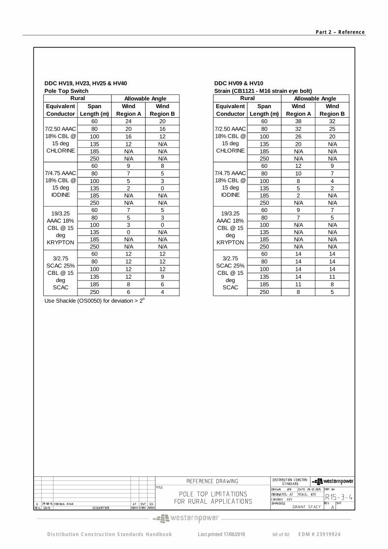
DDC HV19, HV23, HV25 & HV40 DDC HV09 & HV10 Pole Top Switch Strain (CB1121 - M16 strain eye bolt)
Equivalent Conductor
Span Length (m)
Wind Region A
Wind Region B
Equivalent Conductor
Span Length (m)
Wind Region A
Wind Region B
60 24 20 60 38 32 80 20 16 80 32 25 100 16 12 100 26 20 135 12 N/A 135 20 N/A 185 N/A N/A 185 N/A N/A 250 N/A N/A 250 N/A N/A 60 9 8 60 12 9 80 7 5 80 10 7 100 5 3 100 8 4 135 2 0 135 5 2 185 N/A N/A 185 2 N/A 250 N/A N/A 250 N/A N/A 60 7 5 60 9 7 80 5 3 100 3 0 135 0 N/A 185 N/A N/A 250 N/A N/A 60 12 12 80 12 12 100 12 12 135 12 9 185 8 6 250 6 4
7/4.75 AAAC 18% CBL @
15 deg IODINE
19/3.25 AAAC 18% CBL @ 15
deg KRYPTON
3/2.75 SCAC 25% CBL @ 15
deg SCAC
Rural Allowable Angle
7/2.50 AAAC 18% CBL @
15 deg CHLORINE
80 7 5 100 N/A N/A 135 N/A N/A 185 N/A N/A 250 N/A N/A 60 14 14 80 14 14 100 14 14 135 14 11 185 11 8 250 8 5
Use Shackle (OS0050) for deviation > 2o
19/3.25 AAAC 18% CBL @ 15
deg KRYPTON
7/4.75 AAAC 18% CBL @
15 deg IODINE
3/2.75 SCAC 25% CBL @ 15
deg SCAC
7/2.50 AAAC 18% CBL @
15 deg CHLORINE
Rural Allowable Angle
D is t r i bu t i on Cons t ruc t ion S tanda rds Handbook Last printed 17/08/2018 58 of 92 EDM # 2 3919924
Pa r t 2 – Re f e r ence
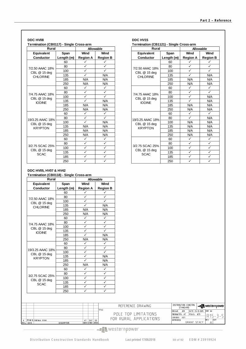
DDC HV08 DDC HV15 Termination (CB0117) - Single Cross-arm Termination (CB1121) - Single Cross-arm
Equivalent Conductor
Span Length (m)
Wind Region A
Wind Region B
Equivalent Conductor
Span Length (m)
Wind Region A
Wind Region B
60 60
80 80
100 100
135 N/A 135 N/A 185 N/A N/A 185 N/A N/A 250 N/A N/A 250 N/A N/A 60 60
80 80
100 100 N/A 135 N/A 135 N/A 185 N/A N/A 185 N/A N/A 250 N/A N/A 250 N/A N/A 60 60
80 80 N/A 100 N/A 135 N/A N/A 185 N/A N/A 250 N/A N/A 60
80
100
135
185
250
Equivalent Conductor
Span Length (m)
Wind Region A
Wind Region B
60
80 100 135 N/A 185 N/A N/A 250 N/A N/A 60
80 100 135 185 N/A 250 N/A N/A 60
80 100 135 N/A 185 N/A 250 N/A N/A 60
80
100
135 185
250
7/4.75 AAAC 18% CBL @ 15 deg
IODINE
19/3.25 AAAC 18% CBL @ 15 deg
KRYPTON
3/2.75 SCAC 25% CBL @ 15 deg
SCAC
7/2.50 AAAC 18% CBL @ 15 deg
CHLORINE
Allowable Rural
100 N/A N/A 135 N/A N/A 185 N/A N/A 250 N/A N/A 60
80
100
135
185
250
DDC HV05, HV07 & HV42 Termination (CB0118) - Single Cross-arm
7/2.50 AAAC 18% CBL @ 15 deg
CHLORINE
7/4.75 AAAC 18% CBL @ 15 deg
IODINE
19/3.25 AAAC 18% CBL @ 15 deg
KRYPTON
Allowable
19/3.25 AAAC 18% CBL @ 15 deg
KRYPTON
3/2.75 SCAC 25% CBL @ 15 deg
SCAC
Rural Allowable
7/2.50 AAAC 18% CBL @ 15 deg
CHLORINE
7/4.75 AAAC 18% CBL @ 15 deg
IODINE
3/2.75 SCAC 25% CBL @ 15 deg
SCAC
Rural
D is t r i bu t i on Cons t ruc t ion S tanda rds Handbook Last printed 17/08/2018 59 of 92 EDM # 2 3919924
Pa r t 2 – Re f e r ence
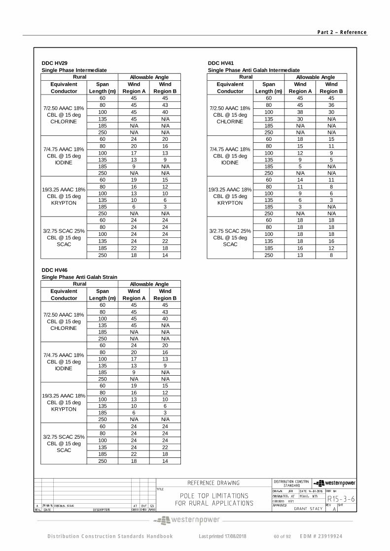
DDC HV29 DDC HV41 Single Phase Intermediate Single Phase Anti Galah Intermediate
Equivalent Conductor
Span Length (m)
Wind Region A
Wind Region B
Equivalent Conductor
Span Length (m)
Wind Region A
Wind Region B
60 45 45 60 45 45 80 45 43 80 45 36 100 45 40 100 38 30 135 45 N/A 135 30 N/A 185 N/A N/A 185 N/A N/A 250 N/A N/A 250 N/A N/A 60 24 20 60 18 15 80 20 16 80 15 11 100 17 13 100 12 9 135 13 9 135 9 5 185 9 N/A 185 5 N/A 250 N/A N/A 250 N/A N/A 60 19 15 60 14 11 80 16 12 80 11 8 100 13 10 135 10 6 185 6 3 250 N/A N/A 60 24 24 80 24 24 100 24 24 135 24 22 185 22 18 250 18 14
Equivalent Conductor
Span Length (m)
Wind Region A
Wind Region B
60 45 45 80 45 43 100 45 40 135 45 N/A 185 N/A N/A 250 N/A N/A 60 24 20 80 20 16 100 17 13 135 13 9 185 9 N/A 250 N/A N/A 60 19 15 80 16 12 100 13 10 135 10 6 185 6 3 250 N/A N/A 60 24 24 80 24 24 100 24 24 135 24 22 185 22 18 250 18 14
Rural
7/2.50 AAAC 18% CBL @ 15 deg
CHLORINE
7/4.75 AAAC 18% CBL @ 15 deg
IODINE
Allowable Angle
19/3.25 AAAC 18% CBL @ 15 deg
KRYPTON
3/2.75 SCAC 25% CBL @ 15 deg
SCAC
100 9 6 135 6 3 185 3 N/A 250 N/A N/A 60 18 18 80 18 18 100 18 18 135 18 16 185 16 12 250 13 8
DDC HV46 Single Phase Anti Galah Strain
Allowable Angle
19/3.25 AAAC 18% CBL @ 15 deg
KRYPTON
Allowable Angle
3/2.75 SCAC 25% CBL @ 15 deg
SCAC
19/3.25 AAAC 18% CBL @ 15 deg
KRYPTON
3/2.75 SCAC 25% CBL @ 15 deg
SCAC
7/4.75 AAAC 18% CBL @ 15 deg
IODINE
Rural
7/2.50 AAAC 18% CBL @ 15 deg
CHLORINE
7/2.50 AAAC 18% CBL @ 15 deg
CHLORINE
Rural
7/4.75 AAAC 18% CBL @ 15 deg
IODINE
D is t r i bu t i on Cons t ruc t ion S tanda rds Handbook Last printed 17/08/2018 60 of 92 EDM # 2 3919924
Pa r t 2 – Re f e r ence
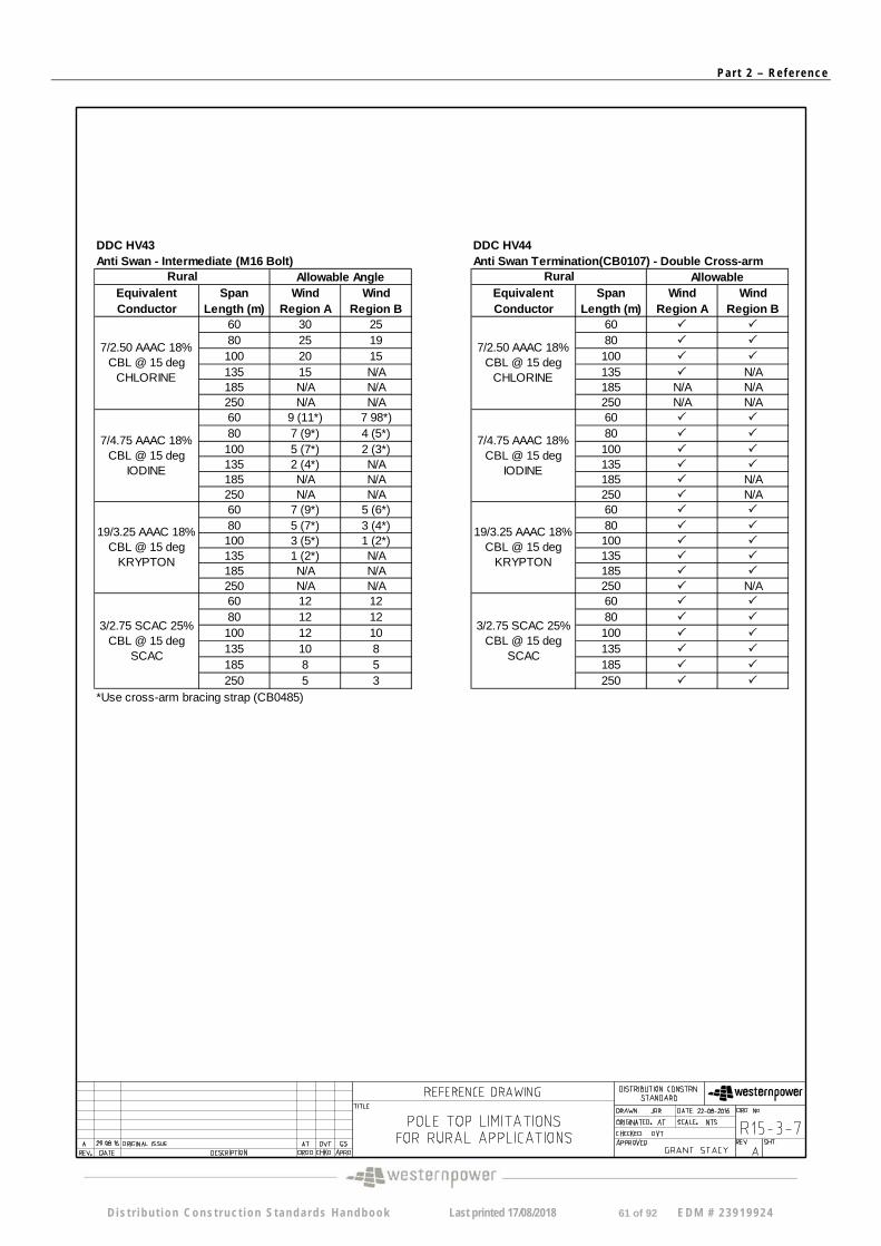
DDC HV43 DDC HV44 Anti Swan - Intermediate (M16 Bolt) Anti Swan Termination(CB0107) - Double Cross-arm
Equivalent Conductor
Span Length (m)
Wind Region A
Wind Region B
Equivalent Conductor
Span Length (m)
Wind Region A
Wind Region B
60 30 25 60
80 25 19 80
100 20 15 100
135 15 N/A 135 N/A 185 N/A N/A 185 N/A N/A 250 N/A N/A 250 N/A N/A 60 9 (11*) 7 98*) 60
80 7 (9*) 4 (5*) 80
100 5 (7*) 2 (3*) 100 135 2 (4*) N/A 135 185 N/A N/A 185 N/A 250 N/A N/A 250 N/A 60 7 (9*) 5 (6*) 80 5 (7*) 3 (4*) 100 3 (5*) 1 (2*) 135 1 (2*) N/A 185 N/A N/A 250 N/A N/A 60 12 12 80 12 12 100 12 10 135 10 8 185 8 5 250 5 3
19/3.25 AAAC 18% CBL @ 15 deg
KRYPTON
3/2.75 SCAC 25% CBL @ 15 deg
SCAC
Rural Allowable Angle
7/2.50 AAAC 18% CBL @ 15 deg
CHLORINE
7/4.75 AAAC 18% CBL @ 15 deg
IODINE
60
80 100 135 185 250 N/A 60
80
100
135
185
250
*Use cross-arm bracing strap (CB0485)
Allowable
7/2.50 AAAC 18% CBL @ 15 deg
CHLORINE
7/4.75 AAAC 18% CBL @ 15 deg
IODINE
19/3.25 AAAC 18% CBL @ 15 deg
KRYPTON
Rural
3/2.75 SCAC 25% CBL @ 15 deg
SCAC
D is t r i bu t i on Cons t ruc t ion S tanda rds Handbook Last printed 17/08/2018 61 of 92 EDM # 2 3919924
Pa r t 2 – Re f e r ence
D i s t r i bu t i on Cons t ruc t ion S tanda rds Handbook Last printed 17/08/2018 62 of 92 EDM # 2 3919924
Pa r t 2 – Re f e r ence
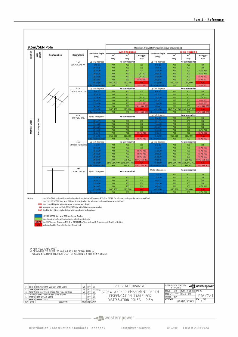
9.5m/5kN Pole
45o
Stay 60
o
Stay Out‐rigger
Stay 45
o
Stay 60
o
Stay Out‐rigger
Stay
4 LV Up to 9 degrees Up to 6 degrees 7/4.75 AAAC 7% 9 to 10 700 700 700 6 to 10 700 700 700
10 to 15 700 700 700 10 to 15 700 700 700 15 to 20 700 700 700 15 to 20 700 700 11/6, 700 20 to 25 700 700 11/6 , 700 20 to 25 700 700 11/6, 700 25 to 30 700 700 11/6 , 700 25 to 30 700 700 SSP1, 700 30 to 45 700 600 SSP1, 600 30 to 45 700 600 SSP1, 500 45 to 90 DSC, 700 DSC, 700 N/A 45 to 90 DSC, 700 DSC, 600 N/A
Inline termination 700 700 SSP1, 600 Inline termination 700 600 SSP1, 500 4 LV Up to 6 degrees Up to 4 degrees
19/3.25 AAAC 7% 6 to 10 700 700 700 4 to 10 700 700 700 10 to 15 700 700 700 10 to 15 700 700 700 15 to 20 700 700 11/6 , 700 15 to 20 700 700 11/6 , 600 20 to 25 700 700 11/6 , 700 20 to 25 700 700 SSP1, 600 25 to 30 700 700 SSP1, 600 25 to 30 700 700 SSP1, 600 30 to 45 700 600 SSP1, SS1, 500 30 to 45 700 500 SSP1, SS1, 500 45 to 90 DSC, 700 DSC, 600 N/A 45 to 90 11/6, DSC, 700 11/6, DSC, 500 N/A
Inline termination 700 600 SSP1, SS1, 500 Inline termination 700 500 SSP1, SS1, 500 4 LV Up to 8 degrees
7/2.75 Cu 15% 8 to 10 700 700 700 10 to 15 700 700 700 10 to 15 700 700 700 15 to 20 700 700 700 15 to 20 700 700 700 20 to 25 700 700 700 20 to 25 700 700 700 25 to 30 700 700 700 25 to 30 700 700 11/6, 700 30 to 45 700 700 SSP1, 700 30 to 45 700 700 SSP1, 700 45 to 90 DSC, 700 DSC, 700 N/A 45 to 90 DSC, 700 DSC, 700 N/A
Inline termination 700 700 SSP1, 700 Inline termination 700 700 SSP1, 700
4 LV Up to 4 degrees Up to 2 degrees 19/0.101 HDBC 15% 4 o 10 700 700 700 2 to 10 700 700 700
10 to 15 700 700 700 10 to 15 700 700 SSP1, 700 15 to 20 700 700 SSP1, 700 15 to 20 700 700 SSP1, 700 20 to 25 700 700 SSP1, 700 20 to 25 700 700 SSP1, 700 25 to 30 700 700 SSP1, 600 25 to 30 700 600 SSP1, 600 30 to 45 600 SS1, 400 SSP1, SS1, 300 30 to 45 600 SS1, 400 SSP1, SS1, 300 45 to 90 11/6, DSC, 600 11/6, DSC, 400 N/A 45 to 90 11/6, DSC, 400 11/6, DSC, 400 N/A
Inline termination 600 SS1, 400 SSP1, SS1, 300 Inline termination 600 SS1, 400 SSP1, SS1, 300
ABC LV ABC 150 7%
13 to 15 700 700 700 18 to 20 700 700 700 15 to 20 700 700 700 20 to 25 700 700 700 20 to 25 700 700 700 25 to 30 700 700 700 25 to 30 700 700 700 30 to 45 700 700 700 30 to 45 700 700 11/6, 700 45 to 90 DSC, 700 DSC, 700 N/A 45 to 90 DSC, 700 DSC, 600 N/A
Inline termination 700 700 700 Inline termination 700 700 11/6, 700
Notes: Use 9.5m/5kN pole with standard embedment depth (Drawing R13‐3 in DCSH) for all cases unless otherwise specified Use 19/2.00 SC/GZ Stay and 200mm Screw Anchor for all cases unless otherwise specified
11/6 Use 11m/6kN pole with standard embedment depth SS1 Increase stay size to 19/2.75 SC/GZ Stay with 300mm screw anchor DSC Double Stay (Stays to be inline with conductor's direction)
19/2.00 SC/GZ Stay and 200mm Screw Anchor Use standard pole with standard embedment depth Use SSP1 as per Drawing R13‐2 in DCSH (11m/6kN pole with Embedment Depth of 2.55m) Not Applicable (Specific Design Required)
Maximum Allowable Protrusion above Ground (mm)
No stay required
No stay required
No stay required Up to 13 degrees
Span
Length
< 60m
Deviation Angle (deg)
No stay required
No stay required
Metro or U
rban
Wind Region A Wind Region B Deviation Angle
(deg)
No stay required
Up to 10 degrees No stay required
No stay required
Up to 18 degrees No stay required
Location
Span
Length
Configuration Descriptions
No stay required
SSP1
N/A
D is t r i bu t i on Cons t ruc t ion S tanda rds Handbook Last printed 17/08/2018 63 of 92 EDM # 2 3919924
Pa r t 2 – Re f e r ence
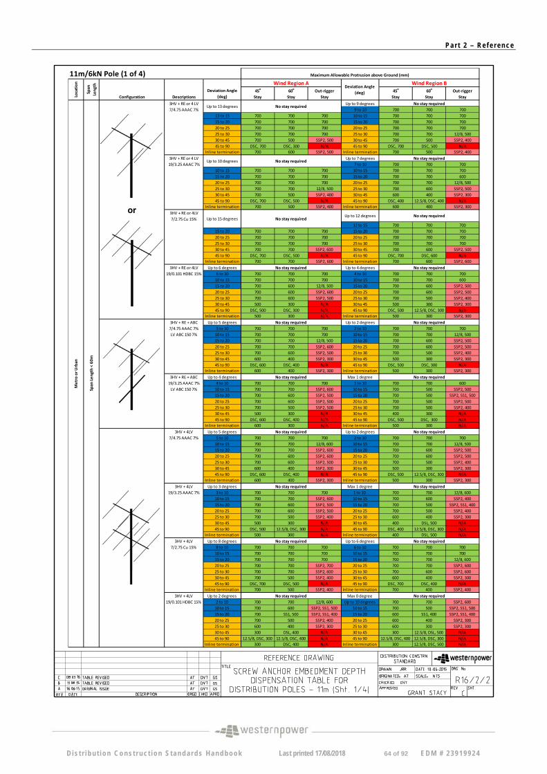
11m/6kN Pole (1 of 4)
45o
Stay 60
o
Stay Out‐rigger
Stay 45
o
Stay 60
o
Stay Out‐rigger
Stay
3HV + RE or 4 LV Up to 9 degrees 7/4.75 AAAC 7% 9 to 10 700 700 700
13 to 15 700 700 700 10 to 15 700 700 700 15 to 20 700 700 700 15 to 20 700 700 700 20 to 25 700 700 700 20 to 25 700 700 700 25 to 30 700 700 700 25 to 30 700 700 12/8, 500 30 to 45 700 500 SSP2, 500 30 to 45 700 500 SSP2, 400 45 to 90 DSC, 700 DSC, 300 N/A 45 to 90 DSC, 700 DSC, 500 N/A
Inline termination 700 600 SSP2, 500 Inline termination 700 500 SSP2, 400
3HV + RE or 4 LV Up to 7 degrees 19/3.25 AAAC 7% 7 to 10 700 700 700
10 to 15 700 700 700 10 to 15 700 700 700 15 to 20 700 700 700 15 to 20 700 700 600 20 to 25 700 700 700 20 to 25 700 700 12/8, 500 25 to 30 700 700 12/8, 500 25 to 30 700 600 SSP2, 500 30 to 45 700 500 SSP2, 400 30 to 45 600 400 SSP2, 300 45 to 90 DSC, 700 DSC, 500 N/A 45 to 90 DSC, 400 12.5/8, DSC, 400 N/A
Inline termination 700 500 SSP2, 400 Inline termination 600 400 SSP2, 300
3HV + RE or 4LV 7/2.75 Cu 15%
12 to 15 700 700 700 15 to 20 700 700 700 15 to 20 700 700 700 20 to 25 700 700 700 20 to 25 700 700 700 25 to 30 700 700 700 25 to 30 700 700 700 30 to 45 700 700 SSP2, 600 30 to 45 700 600 SSP2, 500 45 to 90 DSC, 700 DSC, 500 N/A 45 to 90 DSC, 700 DSC, 600 N/A
Inline termination 700 700 SSP2, 600 Inline termination 700 600 SSP2, 600
3HV + RE or 4LV Up to 6 degrees Up to 4 degrees 19/0.101 HDBC 15% 6 to 10 700 700 700 4 to 10 700 700 700
10 to 15 700 700 700 10 to 15 700 700 600 15 to 20 700 600 12/8, 500 15 to 20 700 600 SSP2, 500 20 to 25 700 600 SSP2, 600 20 to 25 700 600 SSP2, 500 25 to 30 700 600 SSP2, 500 25 to 30 700 500 SSP2, 400 30 to 45 500 300 N/A 30 to 45 500 300 SSP2, 300 45 to 90 DSC, 500 DSC, 300 N/A 45 to 90 DSC, 500 12.5/8, DSC, 300 N/A
Inline termination 500 300 N/A Inline termination 500 300 SSP2, 300
3HV + RE + ABC Up to 5 degrees Up to 2 degrees 7/4.75 AAAC 7% 5 to 10 700 700 700 2 to 10 700 700 700 LV ABC 150 7% 10 to 15 700 700 700 10 to 15 700 700 12/8, 500
15 to 20 700 700 12/8, 500 15 to 20 700 600 SSP2, 500 20 to 25 700 700 SSP2, 600 20 to 25 700 600 SSP2, 500 25 to 30 700 600 SSP2, 500 25 to 30 700 500 SSP2, 400 30 to 45 600 400 SSP2, 300 30 to 45 500 300 SSP2, 300 45 to 90 DSC, 600 DSC, 400 N/A 45 to 90 DSC, 500 DSC, 300 N/A
Inline termination 600 400 SSP2, 300 Inline termination 500 300 SSP2, 300
3HV + RE + ABC Up to 4 degrees Max 1 degree 19/3.25 AAAC 7% 4 to 10 700 700 700 1 to 10 700 700 600 LV ABC 150 7% 10 to 15 700 700 SSP2, 600 10 to 15 700 500 SSP2, 500
15 to 20 700 600 SSP2, 500 15 to 20 700 500 SSP2, SS1, 500 20 to 25 700 600 SSP2, 500 20 to 25 700 500 SSP2, 500 25 to 30 700 500 SSP2, 500 25 to 30 700 500 SSP2, 400 30 to 45 500 300 N/A 30 to 45 400 300 N/A 45 to 90 DSC, 600 DSC, 400 N/A 45 to 90 DSC, 500 DSC, 300 N/A
Inline termination 600 300 N/A Inline termination 500 300 N/A 3HV + 4LV Up to 5 degrees Up to 2 degrees
7/4.75 AAAC 7% 5 to 10 700 700 700 2 to 10 700 700 700 10 to 15 700 700 12/8, 600 10 to 15 700 700 12/8, 500 15 to 20 700 700 SSP2, 600 15 to 20 700 600 SSP2, 500 20 to 25 700 600 SSP2, 600 20 to 25 700 600 SSP2, 500 25 to 30 700 600 SSP2, 500 25 to 30 700 500 SSP2, 400 30 to 45 600 400 SSP2, 300 30 to 45 500 300 SSP2, 300 45 to 90 DSC, 600 DSC, 400 N/A 45 to 90 DSC, 500 12.5/8, DSC, 300 N/A
Inline termination 600 400 SSP2, 300 Inline termination 500 300 SSP2, 300 3HV + 4LV Up to 3 degrees Max 1 degree
19/3.25 AAAC 7% 3 to 10 700 700 700 1 to 10 700 700 12/8, 600 10 to 15 700 700 SSP2, 600 10 to 15 700 600 SSP2, 400 15 to 20 700 600 SSP2, 500 15 to 20 700 500 SSP2, SS1, 400 20 to 25 700 600 SSP2, 500 20 to 25 700 500 SSP2, 400 25 to 30 700 500 SSP2, 400 25 to 30 600 400 SSP2, 300 30 to 45 500 300 N/A 30 to 45 400 DSL, 500 N/A 45 to 90 DSC, 500 12.5/8, DSC, 300 N/A 45 to 90 DSC, 400 12.5/8, DSC, 300 N/A
Inline termination 500 300 N/A Inline termination 400 DSL, 500 N/A 3HV + 4LV Up to 8 degrees Up to 6 degrees
7/2.75 Cu 15% 8 to 10 700 700 700 6 to 10 700 700 700 10 to 15 700 700 700 10 to 15 700 700 700 15 to 20 700 700 700 15 to 20 700 700 12/8, 600 20 to 25 700 700 SSP2, 700 20 to 25 700 700 SSP2, 600 25 to 30 700 700 SSP2, 600 25 to 30 700 600 SSP2, 600 30 to 45 700 500 SSP2, 400 30 to 45 600 400 SSP2, 300 45 to 90 DSC, 700 DSC, 500 N/A 45 to 90 DSC, 700 DSC, 400 N/A
Inline termination 700 500 SSP2, 400 Inline termination 700 400 SSP2, 400 3HV + 4LV Up to 2 degrees Max 0 degree
19/0.101 HDBC 15% 2 to 10 700 700 12/8, 600 Up to 10 degrees 700 700 SSP2, 600 10 to 15 700 600 SSP2, SS1, 500 10 to 15 700 500 SSP2, SS1, 500 15 to 20 700 SS1, 500 SSP2, SS1, 400 15 to 20 600 SS1, 400 SSP2, SS1, 400 20 to 25 700 500 SSP2, 400 20 to 25 600 400 SSP2, 300 25 to 30 600 400 SSP2, 300 25 to 30 600 300 SSP2, 300 30 to 45 300 DSL, 400 N/A 30 to 45 300 12.5/8, DSL, 500 N/A 45 to 90 12.5/8, DSC, 300 12.5/8, DSC, 400 N/A 45 to 90 12.5/8, DSC, 400 12.5/8, DSC, 300 N/A
Inline termination 300 DSC, 400 N/A Inline termination 300 12.5/8, DSC, 500 N/A
Maximum Allowable Protrusion above Ground (mm)
Deviation Angle (deg)
Wind Region B
No stay required
No stay required
No stay required
Location
Span
Length
Configuration Descriptions
Deviation Angle (deg)
Wind Region A
No stay required
No stay required
No stay required
No stay required
Up to 12 degrees
Span
Length
< 60m
or
No stay required
No stay required
No stay required
No stay required
No stay required
Up to 13 degrees
Up to 15 degrees
Metro or U
rban
No stay required
No stay required
No stay required
No stay required
No stay required
No stay required
No stay required
Up to 10 degrees No stay required
D is t r i bu t i on Cons t ruc t ion S tanda rds Handbook Last printed 17/08/2018 64 of 92 EDM # 2 3919924
Pa r t 2 – Re f e r ence
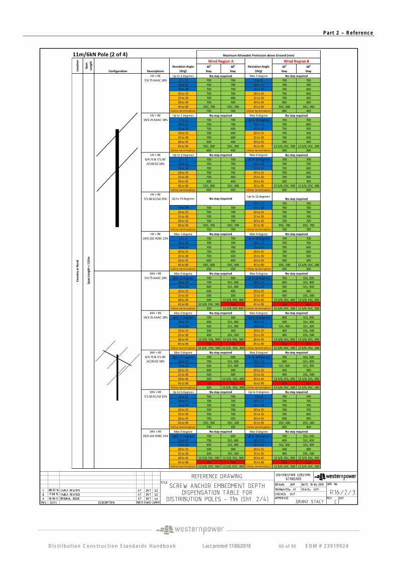
11m/6kN Pole (2 of 4)
45o
Stay 60
o
Stay 45
o
Stay 60
o
Stay
HV + RE Up to 2 degrees Max 1 degree 7/4.75 AAAC 18% 2 to 10 700 700 1 to 10 700 700
10 to 15 700 700 10 to 15 700 700 15 to 20 700 700 15 to 20 700 600 20 to 25 700 700 20 to 25 700 600 25 to 30 700 600 25 to 30 700 500 30 to 45 700 500 30 to 45 600 400 45 to 90 DSC, 700 DSC, 500 45 to 90 DSC, 600 DSC, 400
Inline termination 700 500 Inline termination 600 400
HV + RE Up to 1 degrees Max 0 degree 19/3.25 AAAC 18% 1 to 10 700 700 Up to 10 degrees 700 700
10 to 15 700 700 10 to 15 700 600 15 to 20 700 600 15 to 20 700 500 20 to 25 700 600 20 to 25 700 500 25 to 30 700 600 25 to 30 700 500 30 to 45 600 400 30 to 45 500 300 45 to 90 DSC, 600 DSC, 400 45 to 90 12.5/8, DSC, 500 12.5/8, DSC, 300
Inline termination 600 400 Inline termination 500 300
HV + RE Up to 2 degrees Max 0 degree 6/4.75 & 7/1.60 2 to 10 700 700 Up to 10 degrees 700 700 ACSR/GZ 18% 10 to 15 700 700 10 to 15 700 700
15 to 20 700 700 15 to 20 700 600 20 to 25 700 700 20 to 25 700 600 25 to 30 700 600 25 to 30 700 500 30 to 45 600 400 30 to 45 500 300 45 to 90 DSC, 600 DSC, 400 45 to 90 12.5/8, DSC, 500 12.5/8, DSC, 300
Inline termination 600 400 Inline termination 500 300
HV + RE 7/1.60 SC/GZ 25%
12 to 15 700 700 15 to 20 700 700 15 to 20 700 700 20 to 25 700 700 20 to 25 700 700 25 to 30 700 700 25 to 30 700 700 30 to 45 700 700 30 to 45 700 700 45 to 90 DSC, 700 DSC, 700 45 to 90 DSC, 700 DSC, 700
Inline termination 700 700 Inline termination 700 700
HV + RE Max 1 degree Max 0 degree 19/0.101 HDBC 23% 1 to 10 700 700 Up to 10 degrees 700 700
10 to 15 700 700 10 to 15 700 700 15 to 20 700 700 15 to 20 700 600 20 to 25 700 600 20 to 25 700 600 25 to 30 700 600 25 to 30 700 500 30 to 45 600 400 30 to 45 500 300 45 to 90 DSC, 600 DSC, 400 45 to 90 DSC, 500 12.5/8, DSC, 300
Inline termination 600 400 Inline termination 500 300
3HV + RE Max 0 degree Max 0 degree 7/4.75 AAAC 18% Upto 10 degrees 700 600 Up to 10 degrees 700 SS1, 500
10 to 15 700 SS1, 500 10 to 15 600 SS1, 400 15 to 20 600 SS1, 400 15 to 20 500 SS1, 300 20 to 25 600 400 20 to 25 500 300 25 to 30 500 300 25 to 30 400 DSL, 300 30 to 45 300 12.5/8, DSL, 400 30 to 45 12.5/8, DSL, 300 12.5/8, DSL, 300 45 to 90 12.5/8, DSC, 300 N/A 45 to 90 N/A N/A
Inline termination 300 12.5/8, DSC 400 Inline termination 12.5/8, DSC, 300 12.5/8, DSC, 300
3HV + RE Max 0 degree Max 0 degree 19/3.25 AAAC 18% Upto 10 degrees 700 500 Up to 10 degrees 600 SS1, 400
10 to 15 600 SS1, 400 10 to 15 500 SS1, 300 15 to 20 500 SS1, 300 15 to 20 SS1, 400 SS1 ,300 20 to 25 500 300 20 to 25 400 DSL, 300 25 to 30 400 DSL, 500 25 to 30 300 DSL, 500 30 to 45 12.5/8, DSL, 500 12.5/8 DSL, 300 30 to 45 12.5/8, DSL, 500 12.5/8, DSL, 300 45 to 90 N/A N/A 45 to 90 N/A N/A
Inline termination 12.5/8, DSC, 500 12.5/8, DSC, 300 Inline termination 12.5/8, DSC, 500 12.5/8, DSC, 300
3HV + RE Max 0 degree Max 0 degree 6/4.75 & 7/1.60 Upto 10 degrees 700 600 Up to 10 degrees 700 SS1, 500 ACSR/GZ 18% 10 to 15 700 SS1, 500 10 to 15 600 SS1, 400
15 to 20 600 SS1, 400 15 to 20 SS1, 500 SS1, 300 20 to 25 600 300 20 to 25 500 300 25 to 30 500 300 25 to 30 400 DSL, 500 30 to 45 300 12.5/8, DSL, 400 30 to 45 12.5/8, DSL, 500 12.5/8, DSL, 300 45 to 90 N/A N/A 45 to 90 N/A N/A
Inline termination 300 12.5/8, DSC, 400 Inline termination 12.5/8, DSC, 500 12.5/8, DSC, 300
3HV + RE Up to 6 degrees Up to 4 degrees 7/1.60 SC/GZ 25% 6 to 10 700 700 4 to 10 700 700
10 to 15 700 700 10 to 15 700 700 15 to 20 700 700 15 to 20 700 700 20 to 25 700 700 20 to 25 700 700 25 to 30 700 700 25 to 30 700 600 30 to 45 700 500 30 to 45 600 400 45 to 90 DSC, 500 DSC, 500 45 to 90 DSC, 600 DSC, 400
Inline termination 700 500 Inline termination 600 400
3HV + RE Max 0 degree Max 0 degree 19/0.101 HDBC 23% Upto 10 degrees 700 600 Up to 10 degrees 700 SS1, 500
10 to 15 700 SS1, 400 10 to 15 600 SS1, 400 15 to 20 600 SS1, 400 15 to 20 SS1, 500 SS1, 300 20 to 25 500 300 20 to 25 500 300 25 to 30 500 DSL, 500 25 to 30 400 DSL, 500 30 to 45 12.5/8, DSL, 500 12.5/8, DSL, 300 30 to 45 12.5/8, DSL, 500 12.5/8, DSL, 300 45 to 90 N/A N/A 45 to 90 N/A N/A
Inline termination 12.5/8, DSC, 500 12.5/8, DSC, 300 Inline termination 12.5/8, DSC, 500 12.5/8, DSC, 300
No stay required
No stay required
No stay required
No stay required
Maximum Allowable Protrusion above Ground (mm)
Wind Region B Deviation Angle
(deg)
No stay required
Span
Length
No stay required
Descriptions
Deviation Angle (deg)
Wind Region A
Configuration
Span
Length
< 135m
Up to 12 degrees
No stay required
No stay required
No stay required
No stay required
No stay required
No stay required
Location
Country or Rural
No stay required
Up to 15 degrees No stay required
No stay required
No stay required
No stay required
No stay required
No stay required
No stay required
D is t r i bu t i on Cons t ruc t ion S tanda rds Handbook Last printed 17/08/2018 65 of 92 EDM # 2 3919924
Pa r t 2 – Re f e r ence
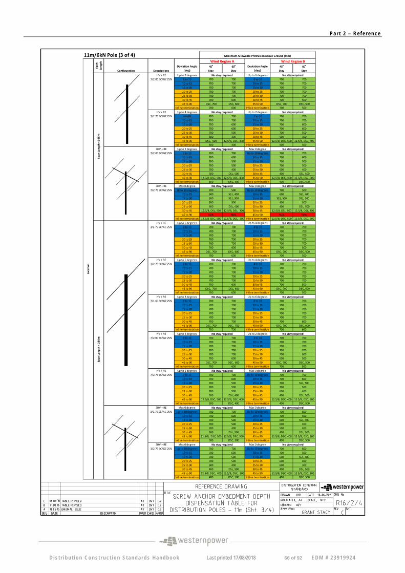
11m/6kN Pole (3 of 4)
45o
Stay 60
o
Stay 45
o
Stay 60
o
Stay
HV + RE Up to 8 degrees Up to 6 degrees 7/2.00 SC/GZ 25% 8 to 10 700 700 6 to 10 700 700
10 to 15 700 700 10 to 15 700 700 15 to 20 700 700 15 to 20 700 700 20 to 25 700 700 20 to 25 700 700 25 to 30 700 700 25 to 30 700 700 30 to 45 700 600 30 to 45 700 500 45 to 90 DSC, 700 DSC, 600 45 to 90 DSC, 700 DSC, 500
Inline termination 700 600 Inline termination 700 500 HV + RE Up to 4 degrees Up to 2 degrees
7/2.75 SC/GZ 25% 4 to10 700 700 2 to 10 700 700 10 to 15 700 700 10 to 15 700 700 15 to 20 700 600 15 to 20 700 600 20 to 25 700 600 20 to 25 700 600 25 to 30 700 500 25 to 30 700 500 30 to 45 600 300 30 to 45 500 300 45 to 90 DSC, 500 12.5/8, DSC, 300 45 to 90 12.5/8, DSC, 500 12.5/8, DSC, 400
Inline termination 500 300 Inline termination 500 300 3HV + RE Up to 2 degrees Max 0 degree
7/2.00 SC/GZ 25% 2 to 10 700 700 Up to 10 degrees 700 700 10 to 15 700 600 10 to 15 700 600 15 to 20 700 500 15 to 20 700 500 20 to 25 700 500 20 to 25 700 500 25 to 30 700 400 25 to 30 600 400 30 to 45 500 DSL, 500 30 to 45 400 DSL, 500 45 to 90 12.5/8, DSC, 500 12.5/8, DSC, 400 45 to 90 12.5/8, DSC, 400 12.5/8, DSC, 300
Inline termination 500 DSC, 500 Inline termination 400 DSC, 500 3HV + RE Max 0 degree Max 0 degree
7/2.75 SC/GZ 25% Upto 10 degrees 700 500 Up to 10 degrees 700 500 10 to 15 600 SS1, 400 10 to 15 600 SS1, 400 15 to 20 500 SS1, 300 15 to 20 SS1, 500 SS1, 300 20 to 25 500 300 20 to 25 400 300 25 to 30 400 DSL, 400 25 to 30 400 DSL, 500 30 to 45 12.5/8, DSL, 500 12.5/8, DSL, 300 30 to 45 12.5/8, DSL, 500 12.5/8, DSL, 300 45 to 90 N/A N/A 45 to 90 N/A N/A
Inline termination 12.5/8, DSC, 500 12.5/8, DSC, 300 Inline termination 12.5/8, DSC, 500 12.5/8, DSC, 300
HV + RE Up to 6 degrees Up to 4 degrees 3/2.75 SC/AC 25% 6 to 10 700 700 4 to 10 700 700
10 to 15 700 700 10 to 15 700 700 15 to 20 700 700 15 to 20 700 700 20 to 25 700 700 20 to 25 700 700 25 to 30 700 700 25 to 30 700 700 30 to 45 700 600 30 to 45 700 500 45 to 90 DSC, 700 DSC, 600 45 to 90 DSC, 700 DSC, 500
Inline termination 700 600 Inline termination 700 500
HV + RE Up to 6 degrees Up to 4 degrees 3/2.75 SC/GZ 25% 6 to 10 700 700 4 to 10 700 700
10 to 15 700 700 10 to 15 700 700 15 to 20 700 700 15 to 20 700 700 20 to 25 700 700 20 to 25 700 700 25 to 30 700 700 25 to 30 700 700 30 to 45 700 600 30 to 45 700 500 45 to 90 DSC, 700 DSC, 600 45 to 90 DSC, 700 DSC, 500
Inline termination 700 600 Inline termination 700 500
HV + RE Up to 8 degrees Up to 6 degrees 7/1.60 SC/GZ 25% 8 to 10 700 700 6 to 10 700 700
10 to 15 700 700 10 to 15 700 700 15 to 20 700 700 15 to 20 700 700 20 to 25 700 700 20 to 25 700 700 25 to 30 700 700 25 to 30 700 700 30 to 45 700 700 30 to 45 700 600 45 to 90 DSC, 700 DSC, 700 45 to 90 DSC, 700 DSC, 600
Inline termination 700 700 Inline termination 700 600 HV + RE Up to 6 degrees Up to 2 degrees
7/2.00 SC/GZ 25% 6 to 10 700 700 2 to 10 700 700 10 to 15 700 700 10 to 15 700 700 15 to 20 700 700 15 to 20 700 700 20 to 25 700 700 20 to 25 700 700 25 to 30 700 700 25 to 30 700 600 30 to 45 700 600 30 to 45 600 500 45 to 90 DSC, 700 DSC, 600 45 to 90 DSC, 700 DSC, 500
Inline termination 700 600 Inline termination 700 500 HV + RE Up to 2 degrees Max 0 degree
7/2.75 SC/GZ 25% 2 to 10 700 700 Up to 10 degrees 700 700 10 to 15 700 600 10 to 15 700 600 15 to 20 700 500 15 to 20 700 SS1, 500 20 to 25 700 500 20 to 25 700 500 25 to 30 700 500 25 to 30 600 400 30 to 45 500 DSL, 400 30 to 45 400 DSL, 500 45 to 90 12.5/8, DSC, 500 12.5/8, DSC, 400 45 to 90 12.5/8, DSC, 400 12.5/8, DSC, 300
Inline termination 500 DSC, 400 Inline termination 400 DSC, 500 3HV + RE Max 0 degree Max 0 degree
3/2.75 SC/AC 25% Up to 10 degrees 700 700 Up to 10 degrees 700 600 10 to 15 700 600 10 to 15 700 500 15 to 20 700 500 15 to 20 600 SS1, 400 20 to 25 700 500 20 to 25 600 400 25 to 30 700 400 25 to 30 500 400 30 to 45 500 DSL, 500 30 to 45 400 DSL, 500 45 to 90 12.5/8, DSC, 500 12.5/8, DSC, 300 45 to 90 12.5/8, DSC, 400 12.5/8, DSC, 300
Inline termination 500 DSC, 500 Inline termination 400 DSC, 500 3HV + RE Max 0 degree Max 0 degree
3/2.75 SC/GZ 25% Up to 10 degrees 700 700 Up to 10 degrees 700 600 10 to 15 700 600 10 to 15 700 500 15 to 20 700 500 15 to 20 600 SS1, 400 20 to 25 700 500 20 to 25 600 400 25 to 30 600 400 25 to 30 600 300 30 to 45 400 DSL, 500 30 to 45 400 DSL, 500 45 to 90 12.5/8, DSC, 400 12.5/8, DSC, 300 45 to 90 12.5/8, DSC, 400 12.5/8, DSC, 300
Inline termination 400 DSC, 500 Inline termination 400 DSC, 500
No stay required
No stay required
Maximum Allowable Protrusion above Ground (mm)
Wind Region A Deviation Angle
(deg)
Wind Region B
Location
Span
Length
Configuration
No stay required
Span
Length
<165m
Descriptions
Deviation Angle (deg)
No stay required
No stay required
No stay required
No stay required No stay required
Span
Length
< 250m
No stay required
No stay required
No stay required
No stay required
No stay required
No stay required
No stay required
No stay required
No stay required
No stay required
No stay required
No stay required
No stay required
No stay required
D is t r i bu t i on Cons t ruc t ion S tanda rds Handbook Last printed 17/08/2018 66 of 92 EDM # 2 3919924

Pa r t 2 – Re f e r ence
Notes: Use 11m/6kN pole with standard embedment depth (Drawing R13‐3 in DCSH) for all cases unless otherwise specified 12.5/8 Use 12.5m/8kN pole with standard embedment depth (Drawing R13‐3 in DCSH)
SS1 Increase stay size to 19/2.75 SC/GZ Stay with 300mm screw anchor DSL Double Stay (both stays inline with bisector load's direction) DSC Double Stay (Stays to be inline with conductor's direction)
19/2.00 SC/GZ Stay and 200mm Screw Anchor for < 20o Deviation
19/2.75 SC/GZ Stay and 300mm Screw Anchor for ≥ 20o Deviation
Use standard pole with standard embedment depth Use Use SSP2 as per Drawing R13‐2 in DCSH (12.5m/8kN pole with Embedment Depth of 2.8m) Not Applicable (Specific Design Required)
11m/6kN Pole (4 of 4)
45o
Stay 60
o
Stay 45
o
Stay 60
o
Stay
HV + RE Up to 6 degrees Up to 2 degrees 3/2.75 SC/AC 25% 6 to 10 700 700 2 to 10 700 700
10 to 15 700 700 10 to 15 700 700 15 to 20 700 700 15 to 20 700 700 20 to 25 700 700 20 to 25 700 700 25 to 30 700 700 25 to 30 700 600 30 to 45 700 500 30 to 45 700 500 45 to 90 DSC, 700 DSC, 500 45 to 90 DSC, 700 DSC, 500
Inline termination 700 500 Inline termination 700 500
HV + RE Up to 6 degrees Up to 2 degrees 3/2.75 SC/GZ 25% 6 to 10 700 700 2 to 10 700 700
10 to 15 700 700 10 to 15 700 700 15 to 20 700 700 15 to 20 700 700 20 to 25 700 700 20 to 25 700 700 25 to 30 700 700 25 to 30 700 600 30 to 45 700 500 30 to 45 700 500 45 to 90 DSC, 700 DSC, 500 45 to 90 DSC, 700 DSC, 500
Inline termination 700 500 Inline termination 700 500
HV + RE Up to 8 degrees up to 4 degrees 7/1.60 SC/GZ 25% 8 to 10 700 700 4 to 10 700 700
10 to 15 700 700 10 to 15 700 700 15 to 20 700 700 15 to 20 700 700 20 to 25 700 700 20 to 25 700 700 25 to 30 700 700 25 to 30 700 700 30 to 45 700 600 30 to 45 700 600 45 to 90 DSC, 700 DSC, 600 45 to 90 DSC, 700 DSC, 600
Inline termination 700 600 Inline termination 700 600
HV + RE Up to 4 degrees Up to 2 degrees 7/2.00 SC/GZ 25% 4 to 10 700 700 2 to 10 700 700
10 to 15 700 700 10 to 15 700 700 15 to 20 700 700 15 to 20 700 600 20 to 25 700 700 20 to 25 700 600 25 to 30 700 700 25 to 30 700 600 30 to 45 700 500 30 to 45 600 400 45 to 90 DSC, 700 12.5/8, DSC, 500 45 to 90 DSC, 600 DSC, 400
Inline termination 700 500 Inline termination 600 400
HV + RE Max 4 degrees Max 0 degree 7/2.75 SC/GZ 25% 4 to 10 700 700 Up to 10 degrees 700 600
10 to 15 700 600 10 to 15 700 500 15 to 20 700 500 15 to 20 700 SS1, 500 20 to 25 700 500 20 to 25 400 400 25 to 30 700 400 25 to 30 600 400 30 to 45 400 DSL, 500 30 to 45 400 DSL, 500 45 to 90 12.5/8, DSC, 400 12.5/8, DSC, 400 45 to 90 12.5/8, DSC, 400 12.5/8, DSC, 300
Inline termination 400 DSC, 500 Inline termination 400 DSC, 500
SSP2
N/A
Location
Span
Length
Span
Length
<300m
No stay required
Descriptions Configuration
Deviation Angle (deg)
Maximum Allowable Protrusion above Ground (mm)
Wind Region A Deviation Angle
(deg)
Wind Region B
No stay required
No stay required
No stay required
No stay required
No stay required
No stay required
No stay required
No stay required
No stay required
D is t r i bu t i on Cons t ruc t ion S tanda rds Handbook Last printed 17/08/2018 67 of 92 EDM # 2 3919924
Pa r t 2 – Re f e r ence
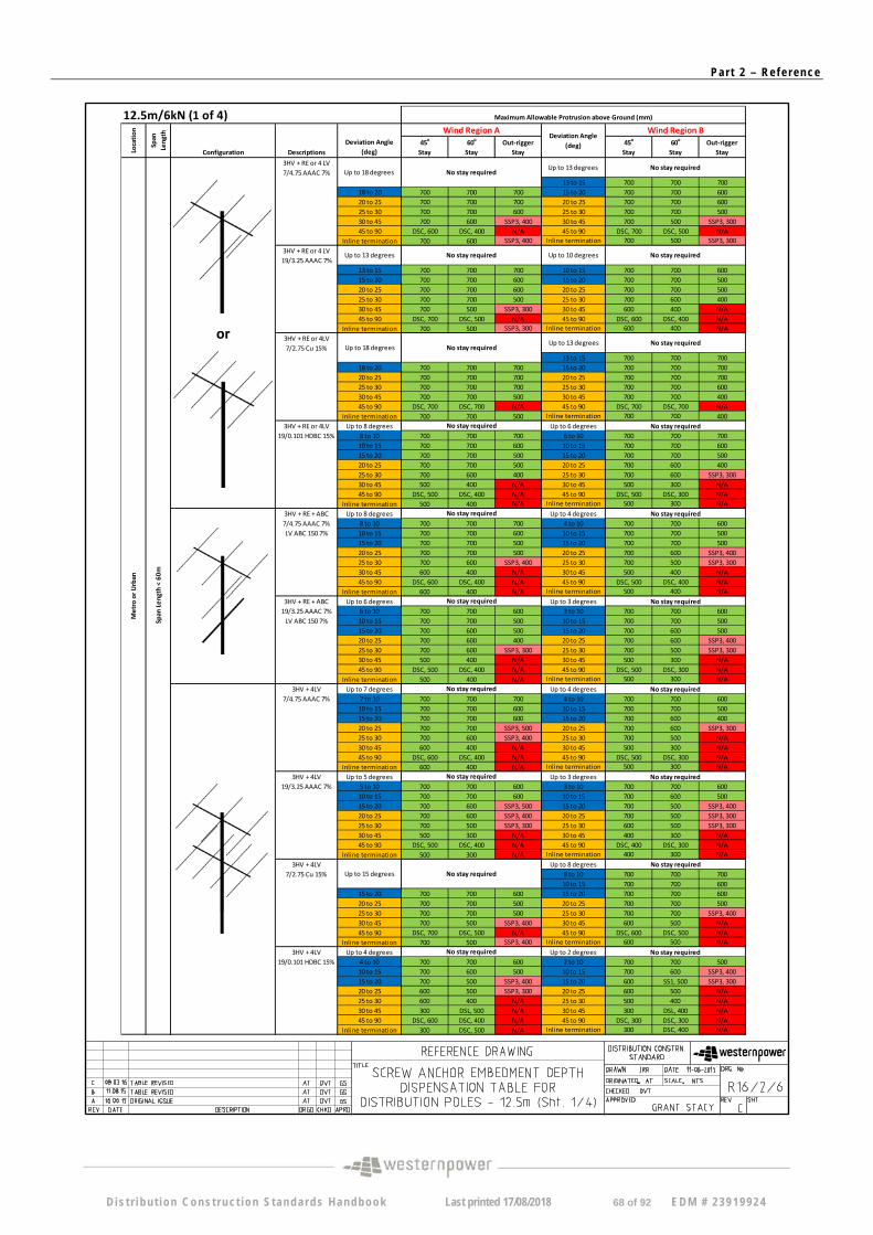
12.5m/6kN (1 of 4)
45o
Stay 60
o
Stay Out‐rigger
Stay 45
o
Stay 60
o
Stay Out‐rigger
Stay
3HV + RE or 4 LV 7/4.75 AAAC 7%
13 to 15 700 700 700 18 to 20 700 700 700 15 to 20 700 700 600 20 to 25 700 700 700 20 to 25 700 700 600 25 to 30 700 700 600 25 to 30 700 700 500 30 to 45 700 600 SSP3, 400 30 to 45 700 500 SSP3, 300 45 to 90 DSC, 600 DSC, 400 N/A 45 to 90 DSC, 700 DSC, 500 N/A
Inline termination 700 600 SSP3, 400 Inline termination 700 500 SSP3, 300
3HV + RE or 4 LV 19/3.25 AAAC 7%
13 to 15 700 700 700 10 to 15 700 700 600 15 to 20 700 700 600 15 to 20 700 700 500 20 to 25 700 700 600 20 to 25 700 700 500 25 to 30 700 700 500 25 to 30 700 600 400 30 to 45 700 500 SSP3, 300 30 to 45 600 400 N/A 45 to 90 DSC, 700 DSC, 500 N/A 45 to 90 DSC, 600 DSC, 400 N/A
Inline termination 700 500 SSP3, 300 Inline termination 600 400 N/A
3HV + RE or 4LV 7/2.75 Cu 15%
13 to 15 700 700 700 18 to 20 700 700 700 15 to 20 700 700 700 20 to 25 700 700 700 20 to 25 700 700 700 25 to 30 700 700 700 25 to 30 700 700 600 30 to 45 700 700 500 30 to 45 700 700 400 45 to 90 DSC, 700 DSC, 700 N/A 45 to 90 DSC, 700 DSC, 700 N/A
Inline termination 700 700 500 Inline termination 700 700 400 3HV + RE or 4LV Up to 8 degrees Up to 6 degrees
19/0.101 HDBC 15% 8 to 10 700 700 700 6 to 10 700 700 700 10 to 15 700 700 600 10 to 15 700 700 600 15 to 20 700 700 500 15 to 20 700 700 500 20 to 25 700 700 500 20 to 25 700 600 400 25 to 30 700 600 400 25 to 30 700 600 SSP3, 300 30 to 45 500 400 N/A 30 to 45 500 300 N/A 45 to 90 DSC, 500 DSC, 400 N/A 45 to 90 DSC, 500 DSC, 300 N/A
Inline termination 500 400 N/A Inline termination 500 300 N/A
3HV + RE + ABC Up to 8 degrees Up to 4 degrees 7/4.75 AAAC 7% 8 to 10 700 700 700 4 to 10 700 700 600 LV ABC 150 7% 10 to 15 700 700 600 10 to 15 700 700 500
15 to 20 700 700 500 15 to 20 700 700 500 20 to 25 700 700 500 20 to 25 700 600 SSP3, 400 25 to 30 700 600 SSP3, 400 25 to 30 700 500 SSP3, 300 30 to 45 600 400 N/A 30 to 45 500 400 N/A 45 to 90 DSC, 600 DSC, 400 N/A 45 to 90 DSC, 500 DSC, 400 N/A
Inline termination 600 400 N/A Inline termination 500 400 N/A
3HV + RE + ABC Up to 6 degrees Up to 3 degrees 19/3.25 AAAC 7% 6 to 10 700 700 600 3 to 10 700 700 600 LV ABC 150 7% 10 to 15 700 700 500 10 to 15 700 700 500
15 to 20 700 600 500 15 to 20 700 600 500 20 to 25 700 600 400 20 to 25 700 600 SSP3, 400 25 to 30 700 600 SSP3, 300 25 to 30 700 500 SSP3, 300 30 to 45 500 400 N/A 30 to 45 500 300 N/A 45 to 90 DSC, 500 DSC, 400 N/A 45 to 90 DSC, 500 DSC, 300 N/A
Inline termination 500 400 N/A Inline termination 500 300 N/A
3HV + 4LV Up to 7 degrees Up to 4 degrees 7/4.75 AAAC 7% 7 to 10 700 700 700 4 to 10 700 700 600
10 to 15 700 700 600 10 to 15 700 700 500 15 to 20 700 700 600 15 to 20 700 600 400 20 to 25 700 700 SSP3, 500 20 to 25 700 600 SSP3, 300 25 to 30 700 600 SSP3, 400 25 to 30 700 500 N/A 30 to 45 600 400 N/A 30 to 45 500 300 N/A 45 to 90 DSC, 600 DSC, 400 N/A 45 to 90 DSC, 500 DSC, 300 N/A
Inline termination 600 400 N/A Inline termination 500 300 N/A
3HV + 4LV Up to 5 degrees Up to 3 degrees 19/3.25 AAAC 7% 5 to 10 700 700 600 3 to 10 700 700 600
10 to 15 700 700 600 10 to 15 700 600 500 15 to 20 700 600 SSP3, 500 15 to 20 700 500 SSP3, 400 20 to 25 700 600 SSP3, 400 20 to 25 700 500 SSP3, 300 25 to 30 700 500 SSP3, 300 25 to 30 600 500 SSP3, 300 30 to 45 500 300 N/A 30 to 45 400 300 N/A 45 to 90 DSC, 500 DSC, 400 N/A 45 to 90 DSC, 400 DSC, 300 N/A
Inline termination 500 300 N/A Inline termination 400 300 N/A
3HV + 4LV Up to 8 degrees 7/2.75 Cu 15% 8 to 10 700 700 700
10 to 15 700 700 600 15 to 20 700 700 600 15 to 20 700 700 600 20 to 25 700 700 500 20 to 25 700 700 500 25 to 30 700 700 500 25 to 30 700 700 SSP3, 400 30 to 45 700 500 SSP3, 400 30 to 45 600 500 N/A 45 to 90 DSC, 700 DSC, 500 N/A 45 to 90 DSC, 600 DSC, 500 N/A
Inline termination 700 500 SSP3, 400 Inline termination 600 500 N/A
3HV + 4LV Up to 4 degrees Up to 2 degrees 19/0.101 HDBC 15% 4 to 10 700 700 600 2 to 10 700 700 500
10 to 15 700 600 500 10 to 15 700 600 SSP3, 400 15 to 20 700 500 SSP3, 400 15 to 20 600 SS1, 500 SSP3, 300 20 to 25 600 500 SSP3, 300 20 to 25 600 500 N/A 25 to 30 600 400 N/A 25 to 30 500 400 N/A 30 to 45 300 DSL, 500 N/A 30 to 45 300 DSL, 400 N/A 45 to 90 DSC, 600 DSC, 400 N/A 45 to 90 DSC, 300 DSC, 300 N/A
Inline termination 300 DSC, 500 N/A Inline termination 300 DSC, 400 N/A
Up to 18 degrees No stay required Up to 13 degrees No stay required
Up to 13 degrees No stay required Up to 10 degrees No stay required
Maximum Allowable Protrusion above Ground (mm)
No stay required No stay required
No stay required No stay required
No stay required No stay required
Up to 15 degrees No stay required
Metro
or U
rban
Location
Span
Length
Configuration Descriptions
Deviation Angle (deg)
Wind Region A Deviation Angle
(deg)
Wind Region B
Up to 18 degrees No stay required Up to 13 degrees
No stay required No stay required
No stay required
No stay required No stay required
No stay required
Span
Length <
60m
or
No stay required No stay required
D is t r i bu t i on Cons t ruc t ion S tanda rds Handbook Last printed 17/08/2018 68 of 92 EDM # 2 3919924
Pa r t 2 – Re f e r ence
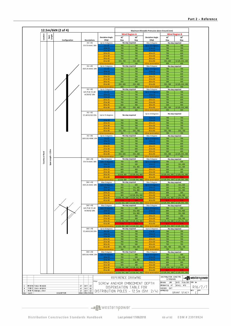
12.5m/6kN (2 of 4)
45o
Stay 60
o
Stay 45
o
Stay 60
o
Stay
HV + RE Up to 3 degrees Max 0 degree 7/4.75 AAAC 18% 3 to 10 700 700 Up to 10 degrees 700 700
10 to 15 700 700 10 to 15 700 700 15 to 20 700 700 15 to 20 700 600 20 to 25 700 700 20 to 25 700 600 25 to 30 700 700 25 to 30 700 600 30 to 45 700 500 30 to 45 600 400 45 to 90 DSC, 700 DSC, 500 45 to 90 DSC, 600 12.5/8, DSC, 400
Inline termination 700 500 Inline termination 600 400
HV + RE Up to 2 degrees Max 0 degree 19/3.25 AAAC 18% 2 to 10 700 700 Up to 10 degrees 700 700
10 to 15 700 700 10 to 15 700 700 15 to 20 700 700 15 to 20 700 600 20 to 25 700 700 20 to 25 700 600 25 to 30 700 600 25 to 30 700 500 30 to 45 600 400 30 to 45 500 300 45 to 90 DSC, 600 DSC, 400 45 to 90 DSC, 500 12.5/8, DSC, 300
Inline termination 600 400 Inline termination 500 300 HV + RE Up to 2 degrees Max 0 degree
6/4.75 & 7/1.60 2 to 10 700 700 Up to 10 degrees 700 700 ACSR/GZ 18% 10 to 15 700 700 10 to 15 700 700
15 to 20 700 700 15 to 20 700 600 20 to 25 700 700 20 to 25 700 600 25 to 30 700 600 25 to 30 700 600 30 to 45 600 400 30 to 45 500 400 45 to 90 DSC, 600 DSC, 400 45 to 90 DSC, 500 12.5/8, DSC, 400
Inline termination 600 400 Inline termination 500 400 HV + RE
7/1.60 SC/GZ 25% 10 to 15 700 700
15 to 20 700 700 15 to 20 700 700 20 to 25 700 700 20 to 25 700 700 25 to 30 700 700 25 to 30 700 700 30 to 45 700 700 30 to 45 700 700 45 to 90 DSC, 700 DSC, 700 45 to 90 DSC, 700 DSC, 700
Inline termination 700 700 Inline termination 700 700
HV + RE Up to 2 degrees Max 0 degree 19/0.101 HDBC 23% 2 to 10 700 700 Up to 10 degrees 700 700
10 to 15 700 700 10 to 15 700 700 15 to 20 700 700 15 to 20 700 600 20 to 25 700 700 20 to 25 700 600 25 to 30 700 600 25 to 30 700 600 30 to 45 600 400 30 to 45 500 400 45 to 90 DSC, 600 DSC, 400 45 to 90 DSC, 500 12.5/8, DSC, 400
Inline termination 600 400 Inline termination 500 400
3HV + RE Max 0 degree Max 0 degree 7/4.75 AAAC 18% Upto 10 degrees 700 600 Up to 10 degrees 700 500
10 to 15 700 500 10 to 15 600 SS1, 400 15 to 20 600 SS1, 400 15 to 20 500 SS1, 300 20 to 25 600 400 20 to 25 500 300 25 to 30 500 300 25 to 30 400 300 30 to 45 12.5/8, 300 12.5/8, DSL, 400 30 to 45 12.5/8, DSL, 500 12.5/8, DSL, 300 45 to 90 N/A N/A 45 to 90 N/A N/A
Inline termination 12.5/8, 300 12.5/8, DSC, 400 Inline termination 12.5/8, DSC, 500 12.5/8, DSC, 300
3HV + RE Max 0 degree Max 0 degree 19/3.25 AAAC 18% Upto 10 degrees 700 600 Up to 10 degrees 600 SS1, 500
10 to 15 600 SS1, 500 10 to 15 500 SS1, 400 15 to 20 500 SS1, 400 15 to 20 400 SS1, 300 20 to 25 500 300 20 to 25 400 300 25 to 30 400 12.5/8, DSL, 500 25 to 30 300 DSL, 500 30 to 45 12.5/8, DSL, 500 12.5/8, DSL, 400 30 to 45 12.5/8, DSL, 400 12.5/8, DSL, 300 45 to 90 N/A N/A 45 to 90 N/A N/A
Inline termination 12.5/8, DSC, 500 12.5/8, DSC, 400 Inline termination 12.5/8, DSC, 400 12.5/8, DSC, 300 3HV + RE Max 0 degree Max 0 degree
6/4.75 & 7/1.60 Upto 10 degrees 700 600 Up to 10 degrees 700 500 ACSR/GZ 18% 10 to 15 700 SS1, 500 10 to 15 600 SS1, 400
15 to 20 600 SS1, 400 15 to 20 500 SS1, 300 20 to 25 600 400 20 to 25 500 300 25 to 30 500 300 25 to 30 400 DSL, 500 30 to 45 12.5/8, DSL, 500 12.5/8, DSL, 400 30 to 45 12.5/8, DSL, 500 12.5/8, DSL, 300 45 to 90 N/A N/A 45 to 90 N/A N/A
Inline termination 12.5/8, DSC, 500 12.5/8, DSC, 400 Inline termination 12.5/8, DSC, 500 12.5/8, DSC, 300 3HV + RE Up to 8 degrees Up to 2 degrees
7/1.60 SC/GZ 25% 8 to 10 700 700 2 to 10 700 700 10 to 15 700 700 10 to 15 700 700 15 to 20 700 700 15 to 20 700 700 20 to 25 700 700 20 to 25 700 700 25 to 30 700 700 25 to 30 700 700 30 to 45 700 500 30 to 45 700 700 45 to 90 DSC, 700 DSC, 500 45 to 90 DSC, 700 DSC, 700
Inline termination 700 500 Inline termination 700 700
3HV + RE Max 0 degree Max 0 degree 19/0.101 HDBC 23% Upto 10 degrees 700 600 Up to 10 degrees 700 500
10 to 15 700 500 10 to 15 600 SS1, 400 15 to 20 600 SS1, 400 15 to 20 500 SS1, 300 20 to 25 500 400 20 to 25 600 300 25 to 30 500 300 25 to 30 400 300 30 to 45 12.5/8, DSL, 500 12.5/8, DSL, 400 30 to 45 12.5/8, DSL, 500 12.5/8, DSL, 300 45 to 90 N/A N/A 45 to 90 N/A N/A
Inline termination 12.5/8, DSC, 500 12.5/8, DSC, 400 Inline termination 12.5/8, DSC, 500 12.5/8, DSC, 300
No stay required
Maximum Allowable Protrusion above Ground (mm)
No stay required No stay required
No stay required No stay required
No stay required No stay required
No stay required No stay required
Deviation Angle (deg) Lo
cation
Span
Length Wind Region A
Deviation Angle (deg)
Wind Region B
Configuration Descriptions
Span
Length
< 135m
Country or Rural
No stay required No stay required
No stay required No stay required
No stay required No stay required
Up to 15 degrees No stay required Up to 10 degrees
No stay required
No stay required
No stay required No stay required
D is t r i bu t i on Cons t ruc t ion S tanda rds Handbook Last printed 17/08/2018 69 of 92 EDM # 2 3919924
Pa r t 2 – Re f e r ence
12.5m/6kN (3 of 4)
45o
Stay 60
o
Stay 45
o
Stay 60
o
Stay
HV + RE Up to 4 degrees 7/2.00 SC/GZ 25% 4 to 10 700 700
10 to 15 700 700 10 to 15 700 700 15 to 20 700 700 15 to 20 700 700 20 to 25 700 700 20 to 25 700 700 25 to 30 700 700 25 to 30 700 700 30 to 45 700 600 30 to 45 700 600 45 to 90 DSC, 700 DSC, 600 45 to 90 DSC, 700 DSC, 600
Inline termination 700 600 Inline termination 700 600 HV + RE Up to 4 degrees Up to 2 degrees
7/2.75 SC/GZ 25% 4 to 10 700 700 2 to 10 700 700 10 to 15 700 700 10 to 15 700 700 15 to 20 700 700 15 to 20 700 600 20 to 25 700 700 20 to 25 700 600 25 to 30 700 600 25 to 30 700 500 30 to 45 600 300 30 to 45 500 300 45 to 90 DSC, 500 12.5/8, DSC, 300 45 to 90 DSC, 500 DSC, 300
Inline termination 600 300 Inline termination 500 300
3HV + RE Up to 2 degrees Max 0 degree 7/2.00 SC/GZ 25% 2 to 10 700 700 Up to 10 degrees 700 700
10 to 15 700 700 10 to 15 700 600 15 to 20 700 600 15 to 20 700 500 20 to 25 700 600 20 to 25 700 500 25 to 30 700 500 25 to 30 600 500 30 to 45 500 200 30 to 45 400 DSL, 500 45 to 90 12.5/8, DSC, 500 12.5/8, DSC, 300 45 to 90 12.5/8, DSC, 400 12.5/8, DSC, 400
Inline termination 500 300 Inline termination 400 DSC, 500
3HV + RE Max 0 degree Max 0 degree 7/2.75 SC/GZ 25% Up to 10 degrees 700 600 Up to 10 degrees 700 500
10 to 15 600 SS1, 500 10 to 15 600 SS1, 400 15 to 20 500 SS1, 400 15 to 20 SS1, 500 SS1, 300 20 to 25 500 300 20 to 25 400 300 25 to 30 400 DSL, 500 25 to 30 400 DSL, 500 30 to 45 12.5/8, DSL, 500 12.5/8, DSL, 300 30 to 45 12.5/8, DSL, 400 12.5/8, DSL, 300 45 to 90 N/A N/A 45 to 90 N/A N/A
Inline termination 12.5/8, DSC, 500 12.5/8, DSC, 300 Inline termination 12.5/8, DSC, 400 12.5/8, DSC, 300
HV + RE Up to 8 degrees Up to 2 degrees 3/2.75 SC/AC 25% 8 to 10 700 700 2 to 10 700 700
10 to 15 700 700 10 to 15 700 700 15 to 20 700 700 15 to 20 700 700 20 to 25 700 700 20 to 25 700 700 25 to 30 700 700 25 to 30 700 700 30 to 45 700 600 30 to 45 700 500 45 to 90 DSC, 700 DSC, 600 45 to 90 DSC, 500 DSC, 300
Inline termination 700 600 Inline termination 700 600 HV + RE Up to 8 degrees Up to 2 degrees
3/2.75 SC/GZ 25% 8 to 10 700 700 2 to 10 700 700 10 to 15 700 700 10 to 15 700 700 15 to 20 700 700 15 to 20 700 700 20 to 25 700 700 20 to 25 700 700 25 to 30 700 700 25 to 30 700 700 30 to 45 700 600 30 to 45 700 500 45 to 90 DSC, 700 DSC, 600 45 to 90 DSC, 700 DSC, 500
Inline termination 700 600 Inline termination 700 500
HV + RE Up to 4 degrees 7/1.60 SC/GZ 25% 4 to 10 700 700
10 to 15 700 700 10 to 15 700 700 15 to 20 700 700 15 to 20 700 700 20 to 25 700 700 20 to 25 700 700 25 to 30 700 700 25 to 30 700 700 30 to 45 700 600 30 to 45 700 700 45 to 90 DSC, 700 DSC, 600 45 to 90 DSC, 700 DSC, 700
Inline termination 700 600 Inline termination 700 700
HV + RE Up to 6 degrees Up to 2 degrees 7/2.00 SC/GZ 25% 6 to 10 700 700 2 to 10 700 700
10 to 15 700 700 10 to 15 700 700 15 to 20 700 700 15 to 20 700 700 20 to 25 700 700 20 to 25 700 700 25 to 30 700 700 25 to 30 700 700 30 to 45 700 700 30 to 45 700 500 45 to 90 DSC, 700 DSC, 700 45 to 90 DSC, 700 DSC, 500
Inline termination 700 700 Inline termination 700 500
HV + RE Up to 2 degrees Max 0 degree 7/2.75 SC/GZ 25% 2 to 10 700 700 Up to 10 degrees 700 700
10 to 15 700 700 10 to 15 700 600 15 to 20 700 600 15 to 20 700 500 20 to 25 700 600 20 to 25 700 500 25 to 30 700 500 25 to 30 600 500 30 to 45 500 300 30 to 45 400 DSL, 500 45 to 90 DSC, 500 DSC, 300 45 to 90 12.5/8, DSC, 400 12.5/8, DSC, 300
Inline termination 500 300 Inline termination 400 DSC, 500
3HV + RE Max 0 degree Max 0 degree 3/2.75 SC/AC 25% Upto 10 degrees 700 700 Up to 10 degrees 700 700
10 to 15 700 600 10 to 15 700 600 15 to 20 700 500 15 to 20 600 500 20 to 25 700 500 20 to 25 600 500 25 to 30 600 500 25 to 30 600 400 30 to 45 500 DSL, 500 30 to 45 400 DSL, 500 45 to 90 DSC, 500 DSC, 300 45 to 90 12.5/8, DSC, 500 12.5/8, DSC, 300
Inline termination 500 DSC, 500 Inline termination 400 DSC, 500 3HV + RE Max 0 degree Max 0 degree
3/2.75 SC/GZ 25% Upto 10 degrees 700 700 Up to 10 degrees 700 700 10 to 15 700 600 10 to 15 700 600 15 to 20 700 500 15 to 20 600 500 20 to 25 700 500 20 to 25 600 500 25 to 30 600 500 25 to 30 600 400 30 to 45 400 DSL, 500 30 to 45 400 DSL, 500 45 to 90 DSC, 400 DSC, 300 45 to 90 12.5/8, DSC, 500 12.5/8, DSC, 300
Inline termination 400 DSC, 500 Inline termination 400 DSC, 500
Up to 10 degrees No stay required
Maximum Allowable Protrusion above Ground (mm)
Location
Span
Length
Configuration Descriptions Deviation Angle
(deg)
Wind Region A Deviation Angle
(deg)
Wind Region B
No stay required
No stay required
No stay required No stay required
No stay required No stay required
Span
Length
< 250m
No stay required
No stay required No stay required
No stay required No stay required
No stay required
No stay required
Span
Length
<165m
No stay required
No stay required No stay required
No stay required No stay required
No stay required No stay required
Up to 10 degrees No stay required
Country or Rural
D is t r i bu t i on Cons t ruc t ion S tanda rds Handbook Last printed 17/08/2018 70 of 92 EDM # 2 3919924
Pa r t 2 – Re f e r ence
12.5m/6kN (4 of 4)
45o
Stay 60
o
Stay 45
o
Stay 60
o
Stay
HV + RE Up to 6 degrees Up to 2 degrees 3/2.75 SC/AC 25% 6 to 10 700 700 2 to 10 700 700
10 to 15 700 700 10 to 15 700 700 15 to 20 700 700 15 to 20 700 700 20 to 25 700 700 20 to 25 700 700 25 to 30 700 700 25 to 30 700 700 30 to 45 700 600 30 to 45 700 500 45 to 90 DSC, 700 DSC, 600 45 to 90 DSC, 700 DSC, 500
Inline termination 700 600 Inline termination 700 500
HV + RE Up to 6 degrees Up to 2 degrees 3/2.75 SC/GZ 25% 6 to 10 700 700 2 to 10 700 700
10 to 15 700 700 10 to 15 700 700 15 to 20 700 700 15 to 20 700 700 20 to 25 700 700 20 to 25 700 700 25 to 30 700 700 25 to 30 700 700 30 to 45 700 600 30 to 45 700 500 45 to 90 DSC, 700 DSC, 600 45 to 90 DSC, 700 DSC, 500
Inline termination 700 600 Inline termination 700 500
HV + RE Up to 4 degrees 7/1.60 SC/GZ 25% 4 to 10 700 700
10 to 15 700 700 10 to 15 700 700 15 to 20 700 700 15 to 20 700 700 20 to 25 700 700 20 to 25 700 700 25 to 30 700 700 25 to 30 700 700 30 to 45 700 700 30 to 45 700 600 45 to 90 DSC, 700 DSC, 700 45 to 90 DSC, 700 DSC, 600
Inline termination 700 700 Inline termination 700 600
HV + RE Up to 6 degrees Up to 2 degrees 7/2.00 SC/GZ 25% 6 to 10 700 700 2 to 10 700 700
10 to 15 700 700 10 to 15 700 700 15 to 20 700 700 15 to 20 700 700 20 to 25 700 700 20 to 25 700 700 25 to 30 700 700 25 to 30 700 600 30 to 45 700 500 30 to 45 600 600 45 to 90 DSC, 700 DSC, 500 45 to 90 DSC, 600 DSC, 500
Inline termination 700 500 Inline termination 600 500
HV + RE Up to 2 degrees Max 0 degree 7/2.75 SC/GZ 25% 2 to 10 700 700 Up to 10 degrees 700 700
10 to 15 700 700 10 to 15 700 600 15 to 20 700 600 15 to 20 700 500 20 to 25 700 600 20 to 25 700 500 25 to 30 700 500 25 to 30 600 400 30 to 45 400 DSL, 500 30 to 45 400 DSL, 500 45 to 90 DSC, 400 DSC, 300 45 to 90 12.5/8, DSC, 400 12.5/8, DSC, 300
Inline termination 400 DSC, 500 Inline termination 400 DSC, 500
Notes: Use 12m/6kN pole with standard embedment depth (Drawing R13‐3 in DCSH) for all cases unless otherwise specified 12.5/8 Use 12.5m/8kN pole with standard embedment depth (Drawing R13‐3 in DCSH)
SS1 Increase stay size to 19/2.75 SC/GZ Stay with 300mm screw anchor DSL Double Stay (both stays inline with bisector load's direction) DSC Double Stay (Stays to be inline with conductor's direction)
19/2.00 SC/GZ Stay and 200mm Screw Anchor for < 20o Deviation
19/2.75 SC/GZ Stay and 300mm Screw Anchor for ≥ 20o Deviation Use standard pole with standard embedment depth Use SSP3 as per Drawing R13‐2 in DCSH (14m/8kN pole with Embedment Depth of 3.0m) Not Applicable (Specific Design Required)
Up to 10 degrees No stay required
No stay required
No stay required
Span
Length
<300m
No stay required No stay required
No stay required No stay required
No stay required No stay required
No stay required
Country or R
ural
Maximum Allowable Protrusion above Ground (mm)
Location
Span
Length
Configuration Descriptions Deviation Angle
(deg)
Wind Region A Deviation Angle
(deg)
Wind Region B
SSP3
N/A
D is t r i bu t i on Cons t ruc t ion S tanda rds Handbook Last printed 17/08/2018 71 of 92 EDM # 2 3919924
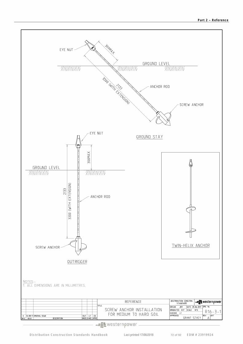
Pa r t 2 – Re f e r ence
D i s t r i bu t i on Cons t ruc t ion S tanda rds Handbook Last printed 17/08/2018 72 of 92 EDM # 2 3919924
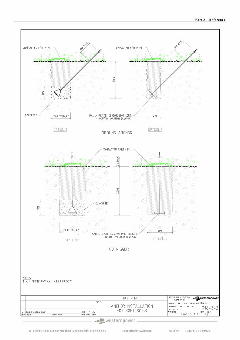
Pa r t 2 – Re f e r ence
D i s t r i bu t i on Cons t ruc t ion S tanda rds Handbook Last printed 17/08/2018 73 of 92 EDM # 2 3919924
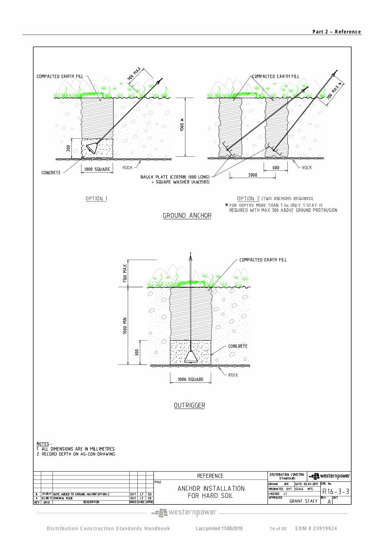
Pa r t 2 – Re f e r ence
D i s t r i bu t i on Cons t ruc t ion S tanda rds Handbook Last printed 17/08/2018 74 of 92 EDM # 2 3919924
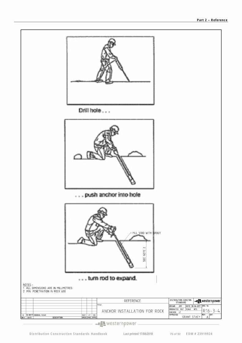
Pa r t 2 – Re f e r ence
D i s t r i bu t i on Cons t ruc t ion S tanda rds Handbook Last printed 17/08/2018 75 of 92 EDM # 2 3919924
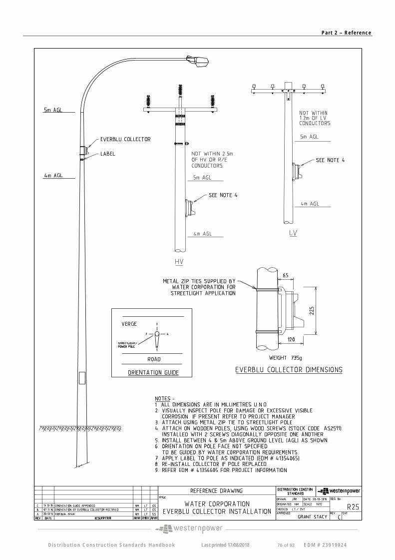
Pa r t 2 – Re f e r ence
D i s t r i bu t i on Cons t ruc t ion S tanda rds Handbook Last printed 17/08/2018 76 of 92 EDM # 2 3919924
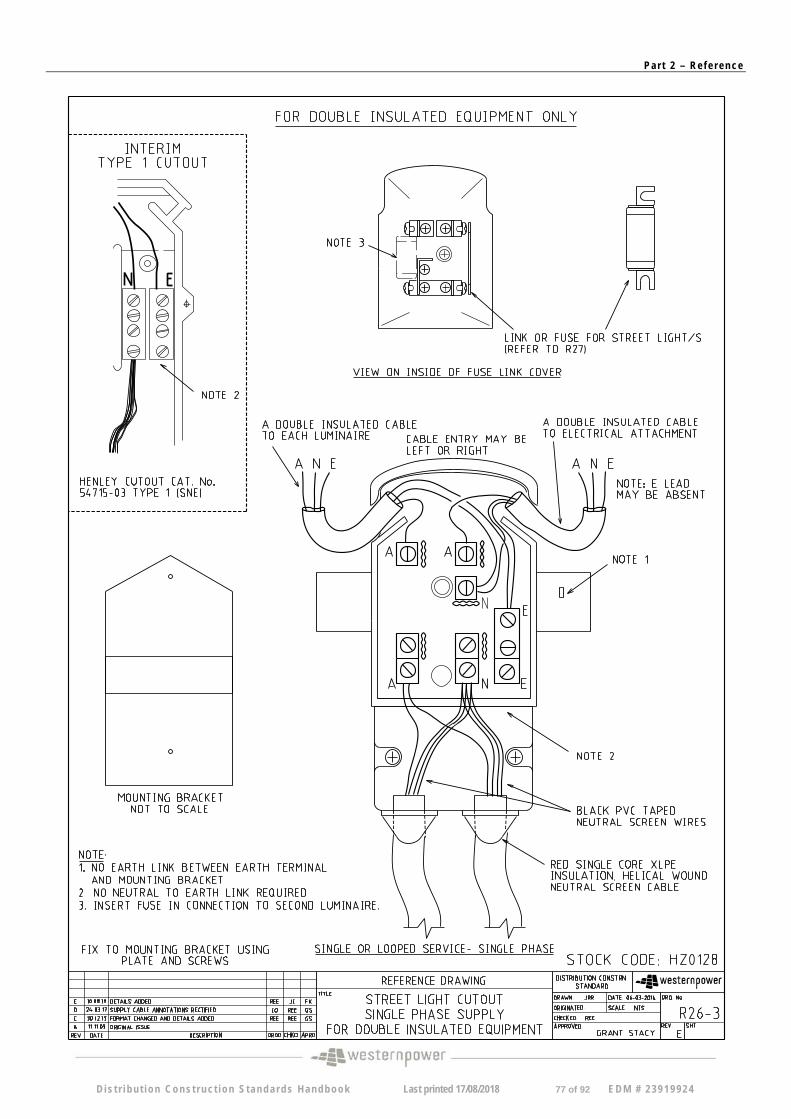
Pa r t 2 – Re f e r ence
D i s t r i bu t i on Cons t ruc t ion S tanda rds Handbook Last printed 17/08/2018 77 of 92 EDM # 2 3919924
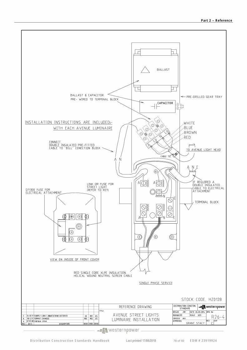
Pa r t 2 – Re f e r ence
D i s t r i bu t i on Cons t ruc t ion S tanda rds Handbook Last printed 17/08/2018 78 of 92 EDM # 2 3919924
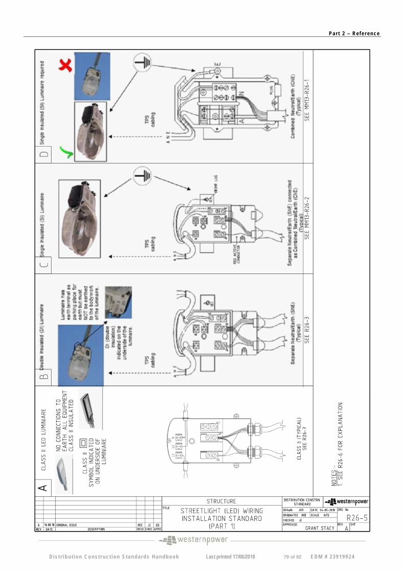
Pa r t 2 – Re f e r ence
D i s t r i bu t i on Cons t ruc t ion S tanda rds Handbook Last printed 17/08/2018 79 of 92 EDM # 2 3919924
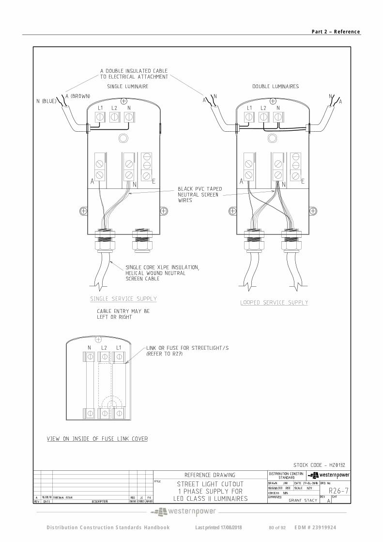
Pa r t 2 – Re f e r ence
D i s t r i bu t i on Cons t ruc t ion S tanda rds Handbook Last printed 17/08/2018 80 of 92 EDM # 2 3919924
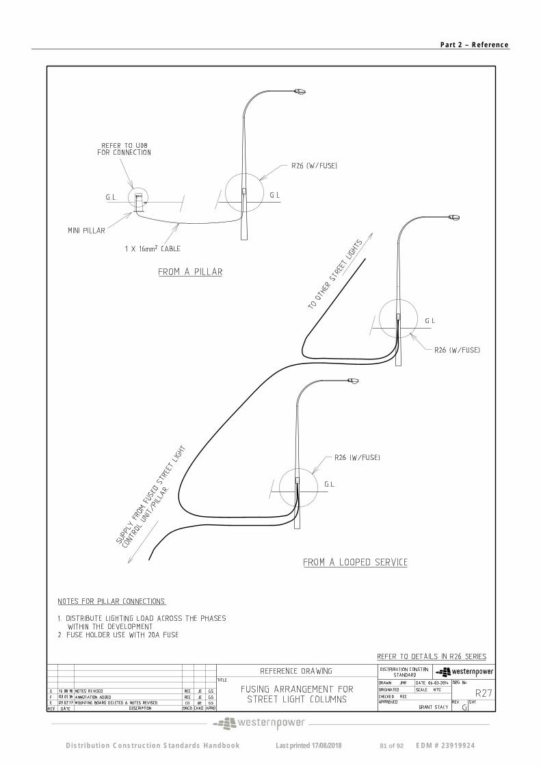
Pa r t 2 – Re f e r ence
D i s t r i bu t i on Cons t ruc t ion S tanda rds Handbook Last printed 17/08/2018 81 of 92 EDM # 2 3919924
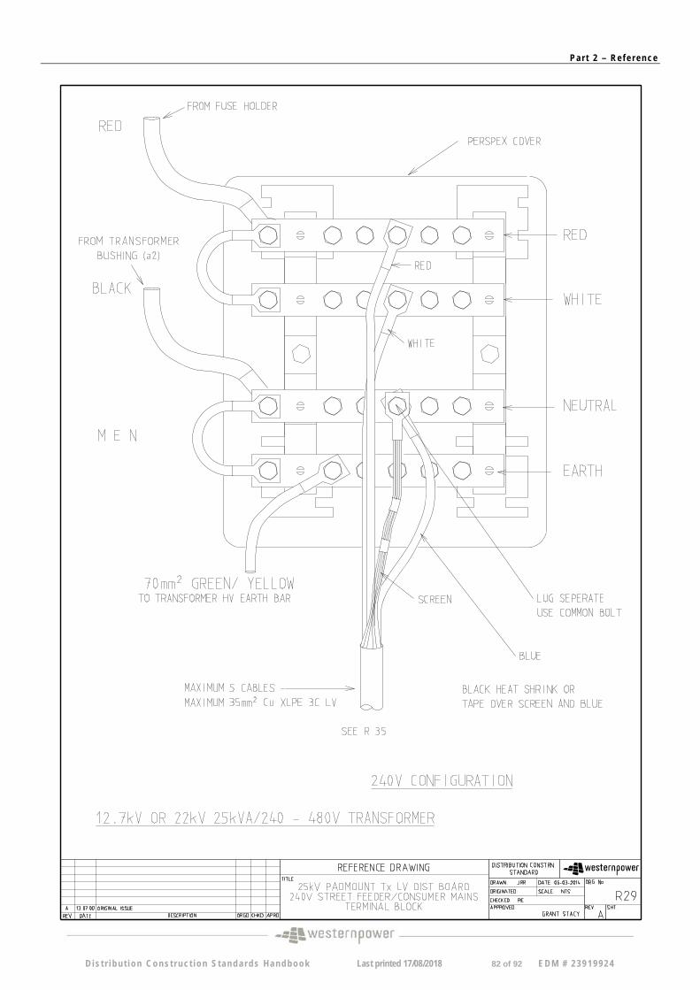
Pa r t 2 – Re f e r ence
D i s t r i bu t i on Cons t ruc t ion S tanda rds Handbook Last printed 17/08/2018 82 of 92 EDM # 2 3919924
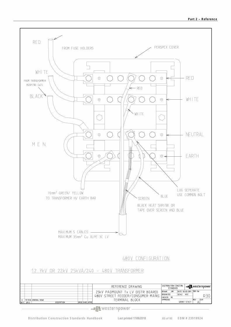
Pa r t 2 – Re f e r ence
D i s t r i bu t i on Cons t ruc t ion S tanda rds Handbook Last printed 17/08/2018 83 of 92 EDM # 2 3919924
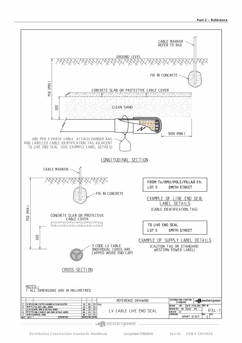
Pa r t 2 – Re f e r ence
D i s t r i bu t i on Cons t ruc t ion S tanda rds Handbook Last printed 17/08/2018 84 of 92 EDM # 2 3919924
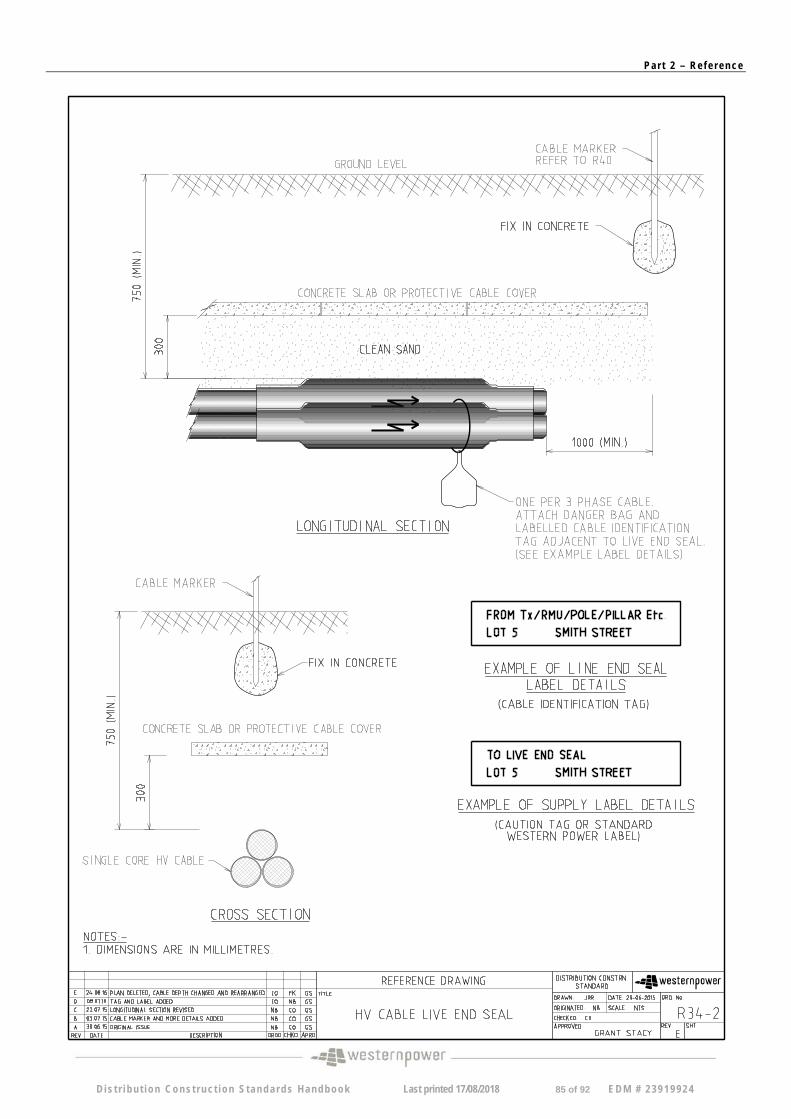
Pa r t 2 – Re f e r ence
D i s t r i bu t i on Cons t ruc t ion S tanda rds Handbook Last printed 17/08/2018 85 of 92 EDM # 2 3919924
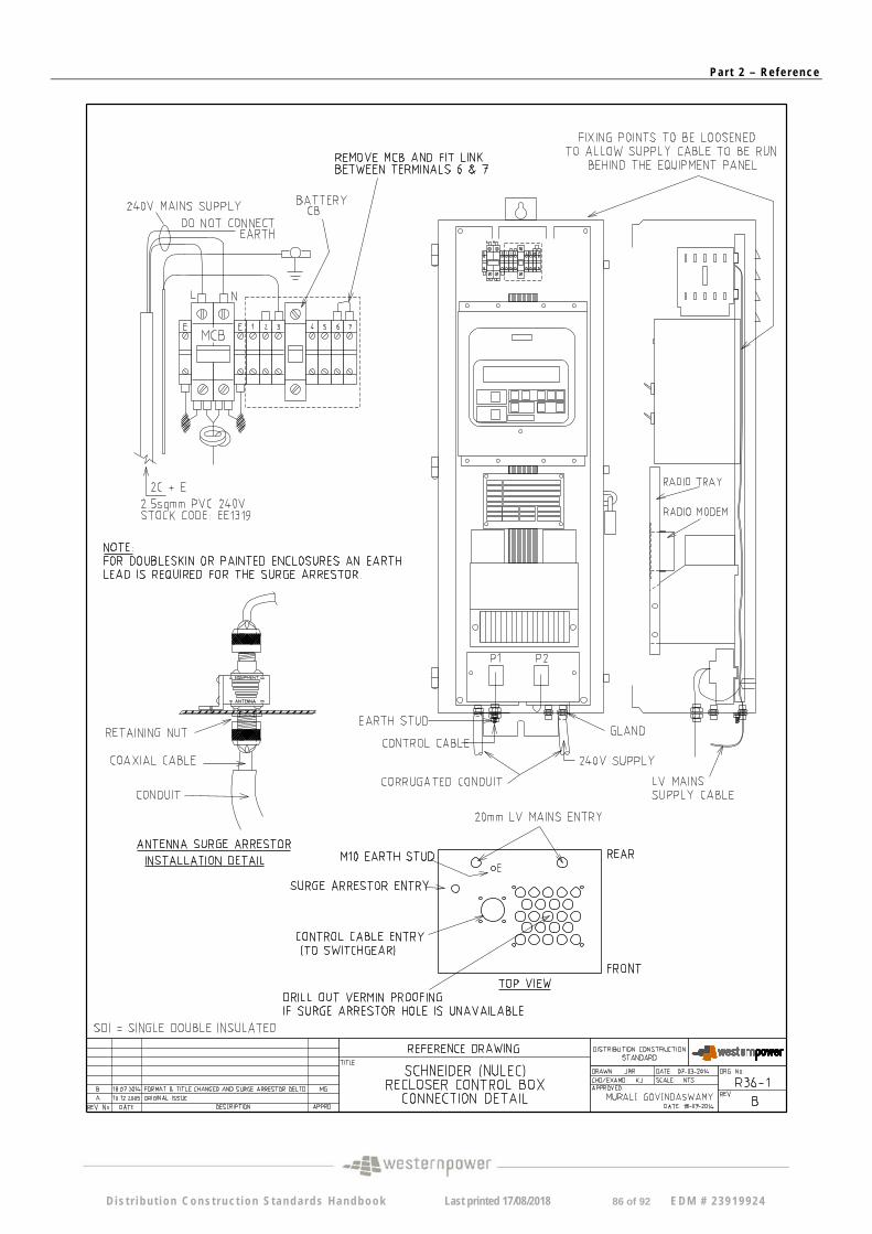
Pa r t 2 – Re f e r ence
D i s t r i bu t i on Cons t ruc t ion S tanda rds Handbook Last printed 17/08/2018 86 of 92 EDM # 2 3919924
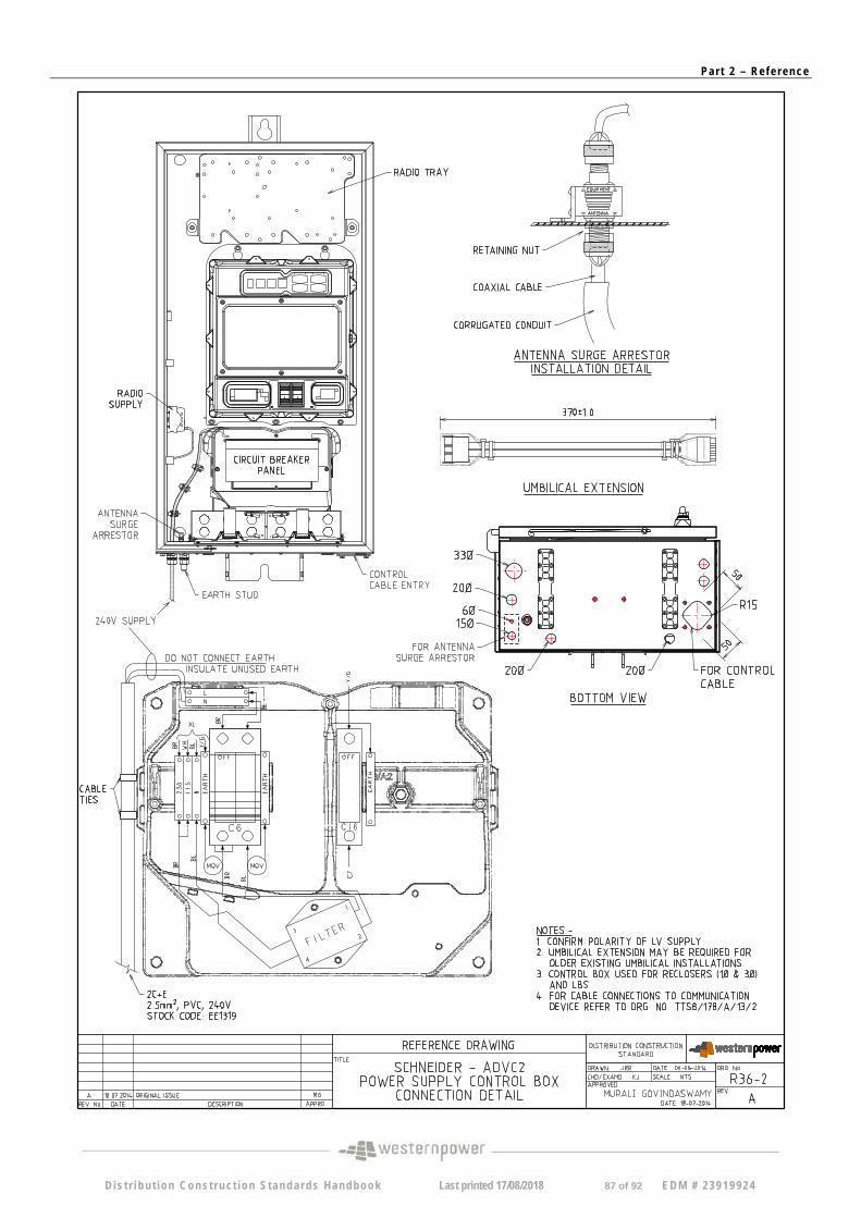
Pa r t 2 – Re f e r ence
D i s t r i bu t i on Cons t ruc t ion S tanda rds Handbook Last printed 17/08/2018 87 of 92 EDM # 2 3919924
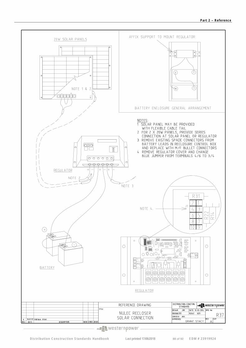
Pa r t 2 – Re f e r ence
D i s t r i bu t i on Cons t ruc t ion S tanda rds Handbook Last printed 17/08/2018 88 of 92 EDM # 2 3919924
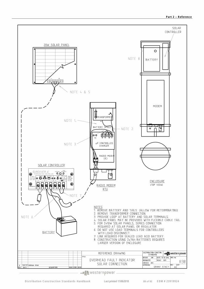
Pa r t 2 – Re f e r ence
D i s t r i bu t i on Cons t ruc t ion S tanda rds Handbook Last printed 17/08/2018 89 of 92 EDM # 2 3919924
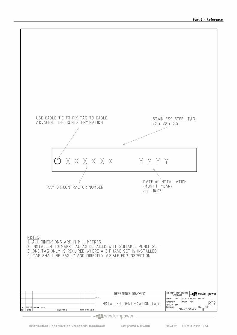
Pa r t 2 – Re f e r ence
D i s t r i bu t i on Cons t ruc t ion S tanda rds Handbook Last printed 17/08/2018 90 of 92 EDM # 2 3919924
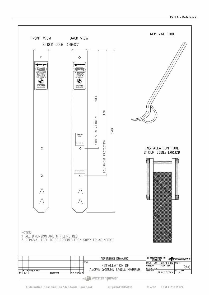
Pa r t 2 – Re f e r ence
D i s t r i bu t i on Cons t ruc t ion S tanda rds Handbook Last printed 17/08/2018 91 of 92 EDM # 2 3919924
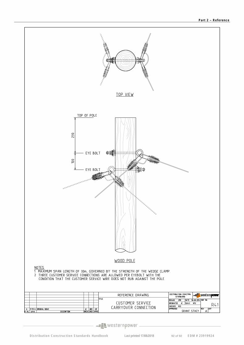
Pa r t 2 – Re f e r ence
D i s t r i bu t i on Cons t ruc t ion S tanda rds Handbook Last printed 17/08/2018 92 of 92 EDM # 2 3919924