Embed Size (px)
Citation preview
Distribution Boxes
Table of Contents
4-1Visit our website: www.ab.com/catalogs
Publication M117-CA001A-EN-P
Gen
eral
Qui
ck S
elec
tion
Intr
od
uctio
n3-
Co
nnec
tion
Sys
tem
s4-
Dis
trib
utio
nB
oxe
sS
afet
yC
onn
ectio
nN
etw
ork
Med
ia
Distribution Boxes
General Information
Mini Distribution Boxes
DC Micro Distribution Boxes
AC Micro Distribution Boxes
Pico Distribution Boxes
IDC Distribution Boxes
Cat. No. Index...................................................................12-1
Quick Selection Guide.........................................................4-2Introduction .........................................................................4-3Configurator.........................................................................4-4
4-Pin, One Signal per Port, Cable Connector...................4-104-Pin, One Signal per Port, Cable with
Mini QD Connector .........................................................4-124-Pin, Two Signals per Port, Cable Connector .................4-144-Pin, One Signal per Port, Terminal Block Connector ....4-164-Pin, One or Two Signals per Port,
M23 Main Connector ......................................................4-18
4-, 6-, and 8-Port, Parallel Wired ......................................4-20
3-Pin, Cable Connector.....................................................4-223-Pin, DC Micro Main Connector......................................4-24
One Signal per Port, Cable Connector .............................4-26
3-Pin, Parallel Wired ............................................................4-64-Pin, Parallel Wired ............................................................4-8
Distribution Boxes
Quick Selection Guide
4-2Visit our website: www.ab.com/catalogs
Publication M117-CA001A-EN-P
General
Quick S
election
Introd
uction
3-Co
nnection
System
s4-D
istributio
nB
oxes
Safety
Co
nnection
Netw
ork M
edia
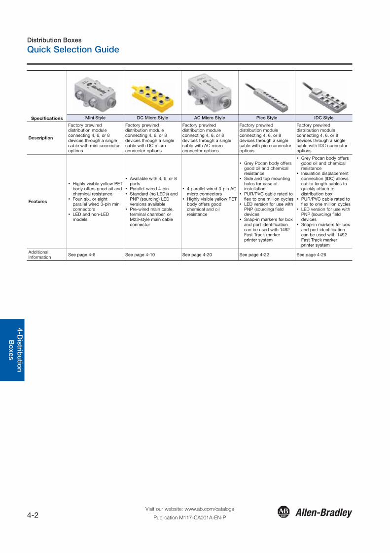
Specifications Mini Style DC Micro Style AC Micro Style Pico Style IDC Style
Description
Factory prewireddistribution moduleconnecting 4, 6, or 8devices through a singlecable with mini connectoroptions
Factory prewireddistribution moduleconnecting 4, 6, or 8devices through a singlecable with DC microconnector options
Factory prewireddistribution moduleconnecting 4, 6, or 8devices through a singlecable with AC microconnector options
Factory prewireddistribution moduleconnecting 4, 6, or 8devices through a singlecable with pico connectoroptions
Factory prewireddistribution moduleconnecting 4, 6, or 8devices through a singlecable with IDC connectoroptions
Features
� Highly visible yellow PETbody offers good oil andchemical resistance
� Four, six, or eightparallel wired 3-pin miniconnectors
� LED and non-LEDmodels
� Available with 4, 6, or 8ports
� Parallel-wired 4-pin� Standard (no LEDs) and
PNP (sourcing) LEDversions available
� Pre-wired main cable,terminal chamber, orM23-style main cableconnector
� 4 parallel wired 3-pin ACmicro connectors
� Highly visible yellow PETbody offers goodchemical and oilresistance
� Grey Pocan body offersgood oil and chemicalresistance
� Side and top mountingholes for ease ofinstallation
� PUR/PVC cable rated toflex to one million cycles
� LED version for use withPNP (sourcing) fielddevices
� Snap-in markers for boxand port identificationcan be used with 1492Fast Track markerprinter system
� Grey Pocan body offersgood oil and chemicalresistance
� Insulation displacementconnection (IDC) allowscut-to-length cables toquickly attach todistribution box
� PUR/PVC cable rated toflex to one million cycles
� LED version for use withPNP (sourcing) fielddevices
� Snap-in markers for boxand port identificationcan be used with 1492Fast Track markerprinter system
AdditionalInformation See page 4-6 See page 4-10 See page 4-20 See page 4-22 See page 4-26
Distribution Boxes
Introduction
4-3Visit our website: www.ab.com/catalogs
Publication M117-CA001A-EN-P
Gen
eral
Qui
ck S
elec
tion
Intr
od
uctio
n3-
Co
nnec
tion
Sys
tem
s4-
Dis
trib
utio
nB
oxe
sS
afet
yC
onn
ectio
nN
etw
ork
Med
ia
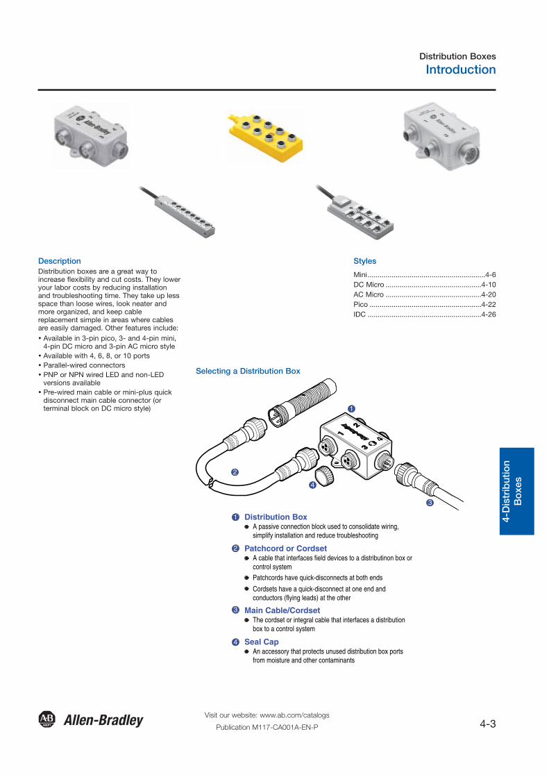
Description Styles
Selecting a Distribution Box
Distribution BoxA passive connection block used to consolidate wiring,simplify installation and reduce troubleshooting
2
1
4
3
1
Patchcord or CordsetA cable that interfaces field devices to a distributinon box orcontrol system
Main Cable/CordsetThe cordset or integral cable that interfaces a distributionbox to a control system
Seal CapAn accessory that protects unused distribution box portsfrom moisture and other contaminants
2
4
3
Patchcords have quick-disconnects at both ends
Cordsets have a quick-disconnect at one end andconductors (flying leads) at the other
Distribution boxes are a great way toincrease flexibility and cut costs. They loweryour labor costs by reducing installationand troubleshooting time. They take up lessspace than loose wires, look neater andmore organized, and keep cablereplacement simple in areas where cablesare easily damaged. Other features include:� Available in 3-pin pico, 3- and 4-pin mini,
4-pin DC micro and 3-pin AC micro style� Available with 4, 6, 8, or 10 ports� Parallel-wired connectors� PNP or NPN wired LED and non-LED
versions available� Pre-wired main cable or mini-plus quick
disconnect main cable connector (orterminal block on DC micro style)
Mini...........................................................4-6DC Micro ................................................4-10AC Micro ................................................4-20Pico ........................................................4-22IDC .........................................................4-26
Distribution Boxes
Mini & DC Micro Style
4-4Visit our website: www.ab.com/catalogs
Publication M117-CA001A-EN-P
Configurator
General
Quick S
election
Introd
uction
3-Co
nnection
System
s4-D
istributio
nB
oxes
Safety
Co
nnection
Netw
ork M
edia
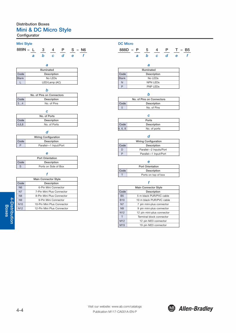
aIlluminated
Code Description
Blank No LEDs
L LED/Lamp (AC)
bNo. of Pins on Connectors
Code Description
3…4 No. of Pins
cNo. of Ports
Code Description
4,6,8 No. of Ports
dWiring Configuration
Code Description
P Parallel—1 Input/Port
ePort Orientation
Code Description
S Ports on Side of Box
fMain Connector Style
Code Description
N6 6-Pin Mini Connector
N7 7-Pin Mini Plus Connector
N8 8-Pin Mini Plus Connector
N9 9-Pin Mini Connector
N10 10-Pin Mini Plus Connector
N12 12-Pin Mini Plus Connector
aIlluminated
Code Description
Blank No LEDs
N NPN LEDs
P PNP LEDs
bNo. of Pins on Connectors
Code Description
5 No. of Pins
cPorts
Code Description
4, 6, 8 No. of ports
dWiring Configuration
Code Description
D Parallel—2 Inputs/Port
P Parallel—1 Input/Port
ePort Orientation
Code Description
T Ports on top of box
fMain Connector Style
Code Description
B5 5 m black PUR/PVC cable
B10 10 m black PUR/PVC cable
N7 7 pin mini-plus connector
N9 9 pin mini-plus connector
N12 12 pin mini-plus connector
T Terminal block connector
M12 12 pin M23 connector
M19 19 pin M23 connector
Mini Style
889N – L 3 4 P S – N6
a b c d e f
DC Micro
888D – P 5 4 P T – B5
a b c d e f

Distribution Boxes
AC Micro & Pico Style
4-5Visit our website: www.ab.com/catalogs
Publication M117-CA001A-EN-P
Configurator
Gen
eral
Qui
ck S
elec
tion
Intr
od
uctio
n3-
Co
nnec
tion
Sys
tem
s4-
Dis
trib
utio
nB
oxe
sS
afet
yC
onn
ectio
nN
etw
ork
Med
ia
aIlluminated
Code Description
Blank No LEDs
L LED/Lamp AC
bNo. of Pins on Connectors
Code Description
3 No. of Pins
cPorts
Code Description
4, 6, 8 No. of ports
dWiring Configuration
Code Description
P Parallel—1 Input/Port
ePort Orientation
Code Description
S Ports on side of box
fMain Connector Style
Code Description
N6 6-pin mini connector
N7 7-pin mini-plus connector
N8 8-pin mini-plus connector
N9 9-pin mini-plus connector
N10 10-pin mini-plus connector
N12 12-pin mini-plus connector
aIlluminated
Code Description
P PNP LEDs
bNo. of Pins on Connectors
Code Description
3 No. of Pins
cNo. of Ports
Code Description
4, 6,8, 10,
12No. of Ports
dWiring Configuration
Code Description
P Parallel—1 Input/Port
ePort Orientation
Code Description
T Ports on Top of Box
fMain Connector Style
Code Description
B5 5 m Black PUR/PVC Cable
B10 10 m Black PUR/PVC Cable
D8 8-Pin DC Micro Connector
AC Micro
898R – L 3 4 P S – N6
a b c d e f
Pico
889P – P 3 4 P T – B5
a b c d e f
Distribution Boxes
Mini Style
4-6Visit our website: www.ab.com/catalogs
Publication M117-CA001A-EN-P
3-Pin, Parallel Wired, Mini Connector
General
Quick S
election
Introd
uction
3-Co
nnection
System
s4-D
istributio
nB
oxes
Safety
Co
nnection
Netw
ork M
edia
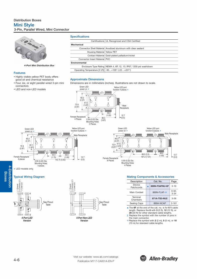
4-Port Mini Distribution Box
Features� Highly visible yellow PET body offers
good oil and chemical resistance� Four, six, or eight parallel wired 3-pin mini
connectors� LED and non-LED models
Specifications
Approximate DimensionsDimensions are in millimeters (inches). Illustrations are not drawn to scale.
Certifications UL Recognized and CSA Certified
Mechanical
Connector Shell Material Anodized aluminum with clear sealant
Housing Material Yellow PET
Contact Material Gold-plated palladium/nickel
Connector Insert Material PVC
Environmental
Enclosure Type Rating NEMA 4, 6P, 12, 13; IP67; 1200 psi washdown
Operating Temperature [C (F)] -30…+105° (-22…+221°)
Green LEDpower on
Yellow LED portfunction 6 places
Male Receptacle
12.7(0.5)
49.0(1.93)
142.75 (5.62)
44.4(1.75)
5.59 (0.22) Dia.Mounting Holes
4 places
Female Receptacle6 places
72.9(2.87)
60.2(2.37)
22.1(1.87)
1
2
3
4
5
6
Green LEDpower on
Yellow LED portfunction 8 places
Male Receptacle
12.7(0.5)
49.0(1.93)88.9 (3.5)
187.2 (7.37)
5.59 (0.22) Dia.Mounting Holes
4 Places
Female Receptacle8 Places
72.9(2.87)
60.2(2.37)
47.5(1.87)
12
34
56
78
Typical Wiring Diagram
1 G
roun
d3
Com
mon
(L1)
2 Lo
ad (L
2)
1 G
roun
d3
Com
mon
(L1)
2 Lo
ad (L
2)
4-Port LEDVersion
4-Port Non-LEDVersion
2
1
4
3
See PinoutTable
See PinoutTable
2
1
4
3
Mating Components & Accessories
Description Cat. No. Page
DevicePatchcords ♣ 889N-F3AFNU-6F 3-10
Main Cordset 889N-F‡AF-�3-32,3-34
TerminalChambers 871A-TS3-NU2 3-26
Sealing Caps 889A-NCAP 3-161
Green LEDpower on
Yellow LED portfunction 4 places
MaleReceptacle
12.7(0.5)98.3
(3.87)
49.0(1.93)
5.59 (0.22) Dia.Mounting Holes
2 Places
Female Receptacle4 Places
72.9(2.87)
60.2(2.37)
47.5(1.87)
1
2
3
4
� LED models only.
♣ The 6F at the end of the cat. no. is for 6 ft cablelength. Replace the 6 with 3 (3 ft), 12 (12 ft), or20 (20 ft) for other standard cable lengths.
‡ Replace the symbol with the number of pins inthe main connector.
�Replace the symbol with 2 (2 m), 5 (5 m), or 10(10 m) for standard cable lengths.

Distribution Boxes
Mini Style
4-7Visit our website: www.ab.com/catalogs
Publication M117-CA001A-EN-P
3-Pin, Parallel Wired, Mini Connector
Gen
eral
Qui
ck S
elec
tion
Intr
od
uctio
n3-
Co
nnec
tion
Sys
tem
s4-
Dis
trib
utio
nB
oxe
sS
afet
yC
onn
ectio
nN
etw
ork
Med
ia
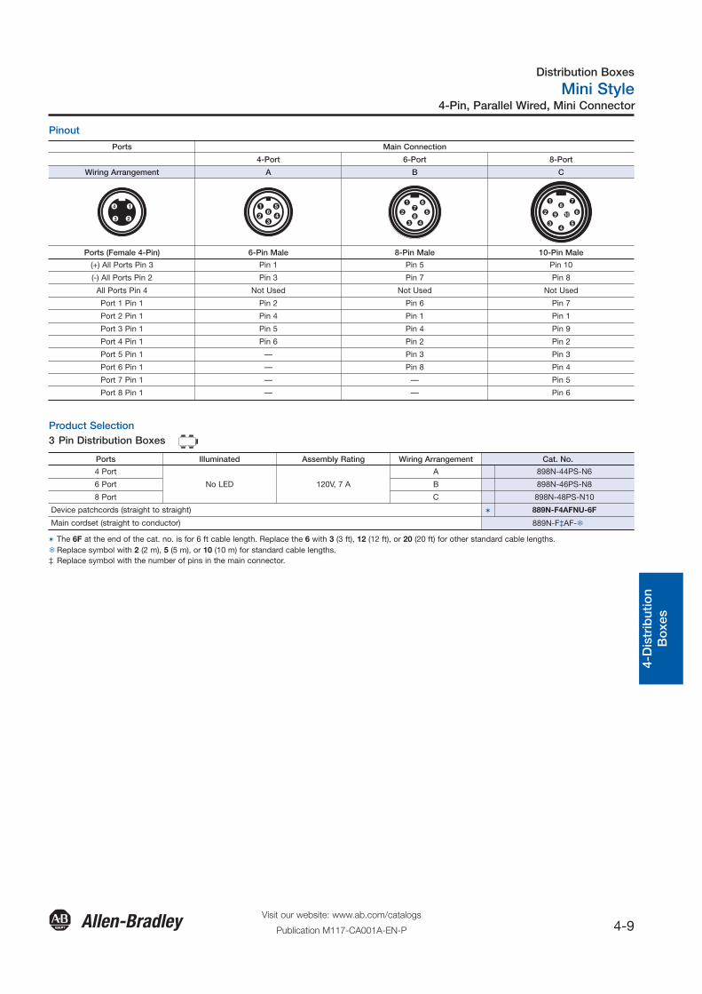
Pinout
Ports Main Connection
4-Port 6-Port 8-Port
Wiring Arrangement A B C D E F
Ports (Female 3-Pin) 6-Pin Male 7-Pin Male 8-Pin Male 9-Pin Male 10-Pin Male 12-Pin Male
LED Ground — Pin 1 — Pin 4 — Pin 7
(+) All Ports Pin 3 Pin 1 Pin 3 Pin 5 Pin 5 Pin 10 Pin 11
(-) All Ports Pin 1 Pin 3 Pin 7 Pin 7 Pin 7 Pin 8 Pin 9
Port 1 Pin 2 Pin 2 Pin 4 Pin 6 Pin 6 Pin 7 Pin 10
Port 2 Pin 2 Pin 4 Pin 5 Pin 1 Pin 1 Pin 1 Pin 1
Port 3 Pin 2 Pin 5 Pin 2 Pin 4 Pin 9 Pin 9 Pin 12
Port 4 Pin 2 Pin 6 Pin 6 Pin 2 Pin 2 Pin 2 Pin 2
Port 5 Pin 2 — — Pin 3 Pin 8 Pin 3 Pin 3
Port 6 Pin 2 — — Pin 8 Pin 3 Pin 4 Pin 4
Port 7 Pin 2 — — — — Pin 5 Pin 5
Port 8 Pin 2 — — — — Pin 6 Pin 6
No Connection — — — — — Pin 8
Product Selection
3 Pin Distribution Boxes
Ports Illuminated Assembly Rating Wiring Arrangement Cat. No.
4 PortNo LED 600V, 7 A A 898N-34PS-N6
LED 120V, 7 A B 898N-L34PS-N7
6 PortNo LED 600V, 7 A C 898N-36PS-N8
LED 120V, 7 A D 898N-L36PS-N9
8 PortNo LED 600V, 7 A E 898N-38PS-N10
LED 120V, 7 A F 898N-L38PS-N12
Device patchcords (straight to straight) � 889N-F3AFNU-6F
Main cordset (straight to conductor) 889N-F‡AF-�
� The 6F at the end of the cat. no. is for 6 ft cable length. Replace the 6 with 3 (3 ft), 12 (12 ft), or 20 (20 ft) for other standard cable lengths.�Replace symbol with 2 (2 m), 5 (5 m), or 10 (10 m) for standard cable lengths.‡ Replace symbol with the number of pins in the main connector.
Distribution Boxes
Mini Style
4-8Visit our website: www.ab.com/catalogs
Publication M117-CA001A-EN-P
4-Pin, Parallel Wired, Mini Connector
General
Quick S
election
Introd
uction
3-Co
nnection
System
s4-D
istributio
nB
oxes
Safety
Co
nnection
Netw
ork M
edia
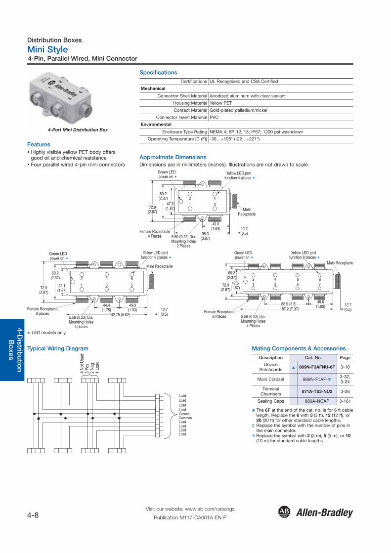
4-Port Mini Distribution Box
Features� Highly visible yellow PET body offers
good oil and chemical resistance� Four parallel wired 4-pin mini connectors
Specifications
Approximate DimensionsDimensions are in millimeters (inches). Illustrations are not drawn to scale.
Certifications UL Recognized and CSA Certified
Mechanical
Connector Shell Material Anodized aluminum with clear sealant
Housing Material Yellow PET
Contact Material Gold-plated palladium/nickel
Connector Insert Material PVC
Environmental
Enclosure Type Rating NEMA 4, 6P, 12, 13; IP67; 1200 psi washdown
Operating Temperature [C (F)] -30…+105° (-22…+221°)
Green LEDpower on
Yellow LED portfunction 4 places
MaleReceptacle
12.7(0.5)98.3
(3.87)
49.0(1.93)
5.59 (0.22) Dia.Mounting Holes
2 Places
Female Receptacle4 Places
72.9(2.87)
60.2(2.37)
47.5(1.87)
1
2
3
4
Green LEDpower on
Yellow LED portfunction 6 places
Male Receptacle
12.7(0.5)
49.0(1.93)
142.75 (5.62)
44.4(1.75)
5.59 (0.22) Dia.Mounting Holes
4 places
Female Receptacle6 places
72.9(2.87)
60.2(2.37)
22.1(1.87)
1
2
3
4
5
6
Green LEDpower on
Yellow LED portfunction 8 places
Male Receptacle
12.7(0.5)
49.0(1.93)88.9 (3.5)
187.2 (7.37)
5.59 (0.22) Dia.Mounting Holes
4 Places
Female Receptacle8 Places
72.9(2.87)
60.2(2.37)
47.5(1.87)
12
34
56
78
Typical Wiring Diagram
LoadLoadLoadLoadGroundCommonLoadLoadLoadLoad
4 N
ot U
sed
3 Po
s2
Neg
1 Lo
ad
Mating Components & Accessories
� LED models only.
Description Cat. No. Page
DevicePatchcords ♣ 889N-F3AFNU-6F 3-10
Main Cordset 889N-F‡AF-�3-32,3-34
TerminalChambers 871A-TS3-NU2 3-26
Sealing Caps 889A-NCAP 3-161
♣ The 6F at the end of the cat. no. is for 6 ft cablelength. Replace the 6 with 3 (3 ft), 12 (12 ft), or20 (20 ft) for other standard cable lengths.
‡ Replace the symbol with the number of pins inthe main connector.
�Replace the symbol with 2 (2 m), 5 (5 m), or 10(10 m) for standard cable lengths.
Distribution Boxes
Mini Style
4-9Visit our website: www.ab.com/catalogs
Publication M117-CA001A-EN-P
4-Pin, Parallel Wired, Mini Connector
Gen
eral
Qui
ck S
elec
tion
Intr
od
uctio
n3-
Co
nnec
tion
Sys
tem
s4-
Dis
trib
utio
nB
oxe
sS
afet
yC
onn
ectio
nN
etw
ork
Med
ia
Pinout
Ports Main Connection
4-Port 6-Port 8-Port
Wiring Arrangement A B C
Ports (Female 4-Pin) 6-Pin Male 8-Pin Male 10-Pin Male
(+) All Ports Pin 3 Pin 1 Pin 5 Pin 10
(-) All Ports Pin 2 Pin 3 Pin 7 Pin 8
All Ports Pin 4 Not Used Not Used Not Used
Port 1 Pin 1 Pin 2 Pin 6 Pin 7
Port 2 Pin 1 Pin 4 Pin 1 Pin 1
Port 3 Pin 1 Pin 5 Pin 4 Pin 9
Port 4 Pin 1 Pin 6 Pin 2 Pin 2
Port 5 Pin 1 — Pin 3 Pin 3
Port 6 Pin 1 — Pin 8 Pin 4
Port 7 Pin 1 — — Pin 5
Port 8 Pin 1 — — Pin 6
Product Selection3 Pin Distribution Boxes
Ports Illuminated Assembly Rating Wiring Arrangement Cat. No.
4 Port
No LED 120V, 7 A
A 898N-44PS-N6
6 Port B 898N-46PS-N8
8 Port C 898N-48PS-N10
Device patchcords (straight to straight) � 889N-F4AFNU-6F
Main cordset (straight to conductor) 889N-F‡AF-�
� The 6F at the end of the cat. no. is for 6 ft cable length. Replace the 6 with 3 (3 ft), 12 (12 ft), or 20 (20 ft) for other standard cable lengths.�Replace symbol with 2 (2 m), 5 (5 m), or 10 (10 m) for standard cable lengths.‡ Replace symbol with the number of pins in the main connector.
Distribution Boxes
DC Micro Style
4-10Visit our website: www.ab.com/catalogs
Publication M117-CA001A-EN-P
4-Pin, One Signal per Port, Cable Connector
General
Quick S
election
Introd
uction
3-Co
nnection
System
s4-D
istributio
nB
oxes
Safety
Co
nnection
Netw
ork M
edia
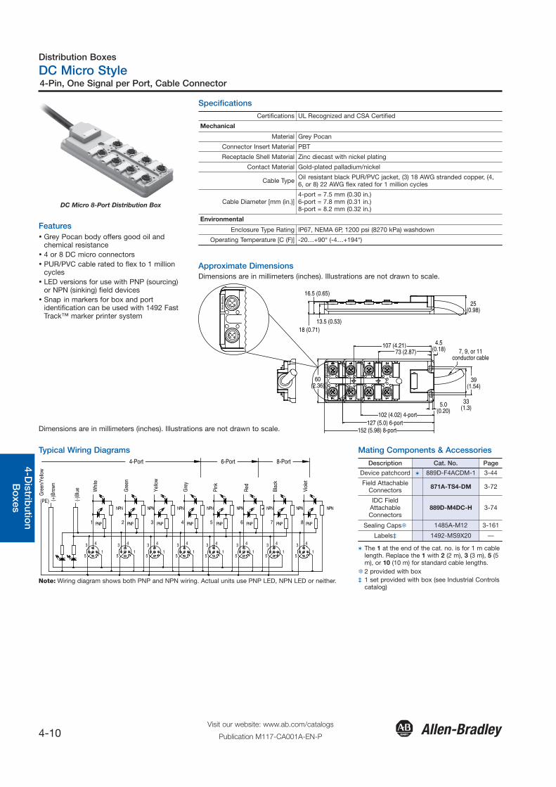
DC Micro 8-Port Distribution Box
Features� Grey Pocan body offers good oil and
chemical resistance� 4 or 8 DC micro connectors� PUR/PVC cable rated to flex to 1 million
cycles� LED versions for use with PNP (sourcing)
or NPN (sinking) field devices� Snap in markers for box and port
identification can be used with 1492 FastTrack™ marker printer system
Specifications
Approximate DimensionsDimensions are in millimeters (inches). Illustrations are not drawn to scale.
Certifications UL Recognized and CSA Certified
Mechanical
Material Grey Pocan
Connector Insert Material PBT
Receptacle Shell Material Zinc diecast with nickel plating
Contact Material Gold-plated palladium/nickel
Cable Type Oil resistant black PUR/PVC jacket, (3) 18 AWG stranded copper, (4,6, or 8) 22 AWG flex rated for 1 million cycles
Cable Diameter [mm (in.)]4-port = 7.5 mm (0.30 in.)6-port = 7.8 mm (0.31 in.)8-port = 8.2 mm (0.32 in.)
Environmental
Enclosure Type Rating IP67, NEMA 6P, 1200 psi (8270 kPa) washdown
Operating Temperature [C (F)] -20…+90° (-4…+194°)
107 (4.21)73 (2.87)
60(2.36)
39(1.54)
4.5(0.18)
25(0.98)
7, 9, or 11conductor cable
33(1.3)
102 (4.02) 4-port127 (5.0) 6-port
152 (5.98) 8-port
13.5 (0.53)
16.5 (0.65)
18 (0.71)89
8D-5
4PT-
B5Al
len-
Brad
ley
-
5.0(0.20)
Alle
n-Br
adle
y
Dimensions are in millimeters (inches). Illustrations are not drawn to scale.
Typical Wiring Diagrams
NPN NPN
PNP PNP
NPN NPN NPN
51
51
51
5
43 4 3 3 4 3 4
15
15
15
15
1
3 4 3 4 3 4 3 4
4-Port
Gre
en/Y
ello
w
(+)B
row
n
(-)Bl
ue Whi
te
Gre
en
(PE)
PNP
NPN
PNP
NPN
PNP PNP PNP PNP
NPN
Yello
w
Gre
y
Pink
Red
Blac
k
Viol
et
6-Port 8-Port
1 2 3 4 5 6 7 8
Note: Wiring diagram shows both PNP and NPN wiring. Actual units use PNP LED, NPN LED or neither.
Mating Components & Accessories
Description Cat. No. Page
Device patchcord � 889D-F4ACDM-1 3-44
Field AttachableConnectors 871A-TS4-DM 3-72
IDC FieldAttachableConnectors
889D-M4DC-H 3-74
Sealing Caps� 1485A-M12 3-161
Labels‡ 1492-MS9X20 —
� The 1 at the end of the cat. no. is for 1 m cablelength. Replace the 1 with 2 (2 m), 3 (3 m), 5 (5m), or 10 (10 m) for standard cable lengths.
� 2 provided with box‡ 1 set provided with box (see Industrial Controls
catalog)
Distribution Boxes
DC Micro Style
4-11Visit our website: www.ab.com/catalogs
Publication M117-CA001A-EN-P
4-Pin, One Signal per Port, Cable Connector
Gen
eral
Qui
ck S
elec
tion
Intr
od
uctio
n3-
Co
nnec
tion
Sys
tem
s4-
Dis
trib
utio
nB
oxe
sS
afet
yC
onn
ectio
nN
etw
ork
Med
ia
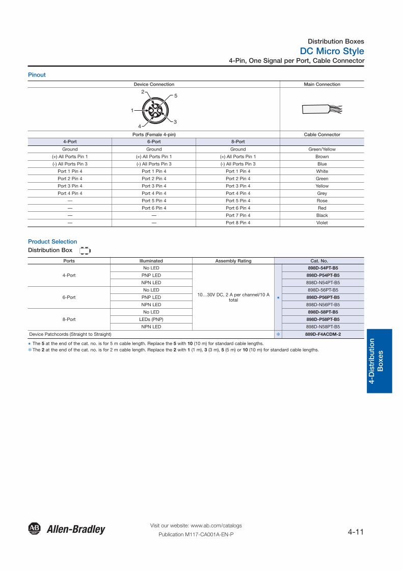
Pinout
Product SelectionDistribution Box
Device Connection Main Connection
5
4 3
1
2
Ports (Female 4-pin) Cable Connector
4-Port 6-Port 8-Port
Ground Ground Ground Green/Yellow
(+) All Ports Pin 1 (+) All Ports Pin 1 (+) All Ports Pin 1 Brown
(-) All Ports Pin 3 (-) All Ports Pin 3 (-) All Ports Pin 3 Blue
Port 1 Pin 4 Port 1 Pin 4 Port 1 Pin 4 White
Port 2 Pin 4 Port 2 Pin 4 Port 2 Pin 4 Green
Port 3 Pin 4 Port 3 Pin 4 Port 3 Pin 4 Yellow
Port 4 Pin 4 Port 4 Pin 4 Port 4 Pin 4 Grey
— Port 5 Pin 4 Port 5 Pin 4 Rose
— Port 6 Pin 4 Port 6 Pin 4 Red
— — Port 7 Pin 4 Black
— — Port 8 Pin 4 Violet
Ports Illuminated Assembly Rating Cat. No.
4-Port
No LED
10…30V DC, 2 A per channel/10 Atotal �
898D-54PT-B5
PNP LED 898D-P54PT-B5
NPN LED 898D-N54PT-B5
6-Port
No LED 898D-56PT-B5
PNP LED 898D-P56PT-B5
NPN LED 898D-N56PT-B5
8-Port
No LED 898D-58PT-B5
LEDs (PNP) 898D-P58PT-B5
NPN LED 898D-N58PT-B5
Device Patchcords (Straight to Straight) � 889D-F4ACDM-2
� The 5 at the end of the cat. no. is for 5 m cable length. Replace the 5 with 10 (10 m) for standard cable lengths. � The 2 at the end of the cat. no. is for 2 m cable length. Replace the 2 with 1 (1 m), 3 (3 m), 5 (5 m) or 10 (10 m) for standard cable lengths.
Distribution Boxes
DC Micro Style
4-12Visit our website: www.ab.com/catalogs
Publication M117-CA001A-EN-P
4-Pin, One Signal per Port, Cable with Mini QD Connector
General
Quick S
election
Introd
uction
3-Co
nnection
System
s4-D
istributio
nB
oxes
Safety
Co
nnection
Netw
ork M
edia
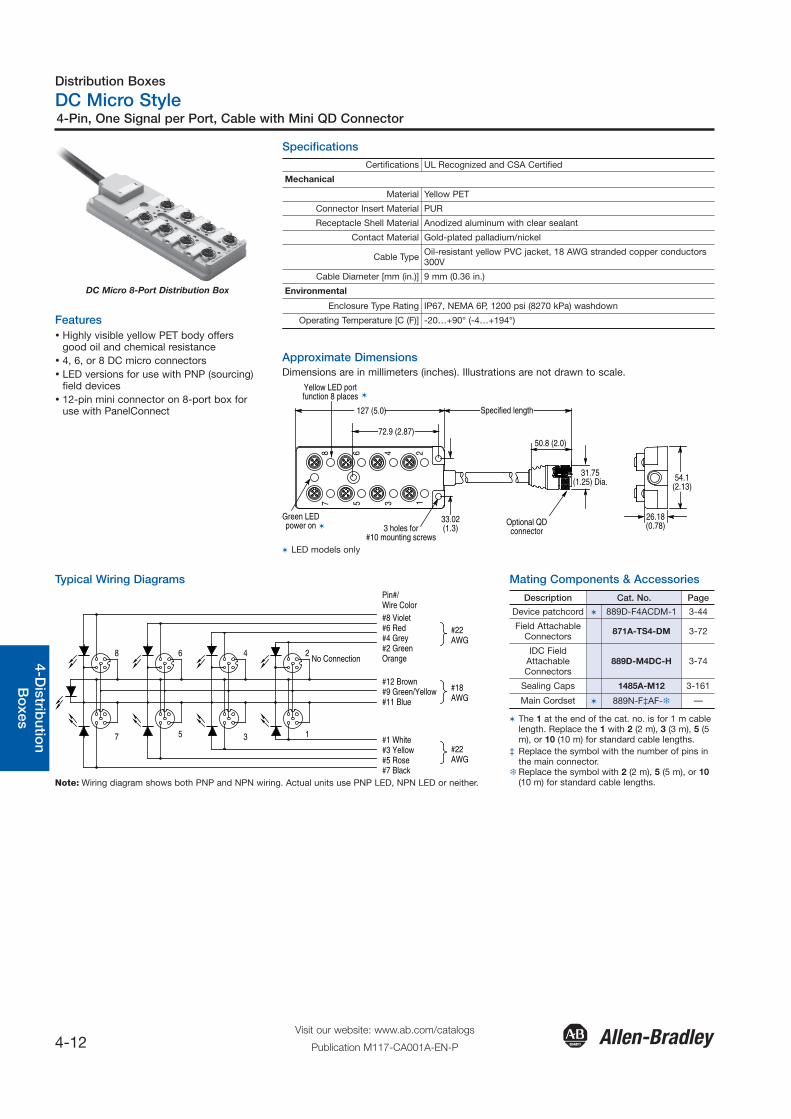
DC Micro 8-Port Distribution Box
Features� Highly visible yellow PET body offers
good oil and chemical resistance� 4, 6, or 8 DC micro connectors� LED versions for use with PNP (sourcing)
field devices� 12-pin mini connector on 8-port box for
use with PanelConnect
Specifications
Approximate DimensionsDimensions are in millimeters (inches). Illustrations are not drawn to scale.
Certifications UL Recognized and CSA Certified
Mechanical
Material Yellow PET
Connector Insert Material PUR
Receptacle Shell Material Anodized aluminum with clear sealant
Contact Material Gold-plated palladium/nickel
Cable Type Oil-resistant yellow PVC jacket, 18 AWG stranded copper conductors300V
Cable Diameter [mm (in.)] 9 mm (0.36 in.)
Environmental
Enclosure Type Rating IP67, NEMA 6P, 1200 psi (8270 kPa) washdown
Operating Temperature [C (F)] -20…+90° (-4…+194°)
72.9 (2.87)
54.1(2.13)
78
5 3 1
46 2127 (5.0) Specified length
33.02(1.3)
50.8 (2.0)
31.75(1.25) Dia.
26.18(0.78)3 holes for
#10 mounting screws
Green LEDpower on
Yellow LED portfunction 8 places
Optional QDconnector
� LED models only
Mating Components & AccessoriesTypical Wiring DiagramsPin#/Wire Color#8 Violet#6 Red#4 Grey#2 GreenOrangeNo Connection
#12 Brown#9 Green/Yellow#11 Blue
#1 White#3 Yellow#5 Rose#7 Black
#22AWG
#22AWG
#18AWG
3 1
4 2
7 5
8 6
Note: Wiring diagram shows both PNP and NPN wiring. Actual units use PNP LED, NPN LED or neither.
Description Cat. No. Page
Device patchcord � 889D-F4ACDM-1 3-44
Field AttachableConnectors 871A-TS4-DM 3-72
IDC FieldAttachableConnectors
889D-M4DC-H 3-74
Sealing Caps 1485A-M12 3-161
Main Cordset � 889N-F‡AF-� —
� The 1 at the end of the cat. no. is for 1 m cablelength. Replace the 1 with 2 (2 m), 3 (3 m), 5 (5m), or 10 (10 m) for standard cable lengths.
‡ Replace the symbol with the number of pins inthe main connector.
�Replace the symbol with 2 (2 m), 5 (5 m), or 10(10 m) for standard cable lengths.
Distribution Boxes
DC Micro Style
4-13Visit our website: www.ab.com/catalogs
Publication M117-CA001A-EN-P
4-Pin, One Signal per Port, Cable with Mini QD Connector
Gen
eral
Qui
ck S
elec
tion
Intr
od
uctio
n3-
Co
nnec
tion
Sys
tem
s4-
Dis
trib
utio
nB
oxe
sS
afet
yC
onn
ectio
nN
etw
ork
Med
ia
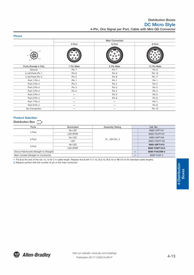
Pinout
Product SelectionDistribution Box
Main Connection
4-Port 6-Port 8-Port
5
4 3
1
2
Ports (Female 4 Pin) 7 Pin Male 9 Pin Male 12 Pin Male
Ground Pin 7 Pin 7 Pin 9
(+) All Ports Pin 1 Pin 6 Pin 9 Pin 12
(-) All Ports Pin 3 Pin 5 Pin 8 Pin 11
Port 1 Pin 4 Pin 1 Pin 1 Pin 1
Port 2 Pin 4 Pin 2 Pin 2 Pin 2
Port 3 Pin 4 Pin 3 Pin 3 Pin 3
Port 4 Pin 4 Pin 4 Pin 4 Pin 4
Port 5 Pin 4 — Pin 5 Pin 5
Port 6 Pin 4 — Pin 6 Pin 6
Port 7 Pin 4 — — Pin 7
Port 8 Pin 4 — — Pin 8
No Connection — — Pin 10
Ports Illuminated Assembly Rating Cat. No.
4 PortNo LED
10…30V DC, 3
898D-54PT-N7
LED (PNP) 898D-P54PT-N7
6 PortNo LED 898D-56PT-N9
LED 898D-P56PT-N9
8 PortNo LED 898D-58PT-N12
LED (PNP) 898D-P58PT-N12
Device Patchcords (Straight to Straight) � 889D-F4ACDM-2
Main Cordset (Straight to Conductor) � 889N-F§AF-2
� The 2 at the end of the cat. no. is for 2 m cable length. Replace the 2 with 1 (1 m), 3 (3 m), 5 (5 m) or 10 (10 m) for standard cable lengths. § Replace symbol with the number of pin in the main conductor.
Distribution Boxes
DC Micro Style
4-14Visit our website: www.ab.com/catalogs
Publication M117-CA001A-EN-P
4-Pin, Two Signals per Port, Cable Connector
General
Quick S
election
Introd
uction
3-Co
nnection
System
s4-D
istributio
nB
oxes
Safety
Co
nnection
Netw
ork M
edia
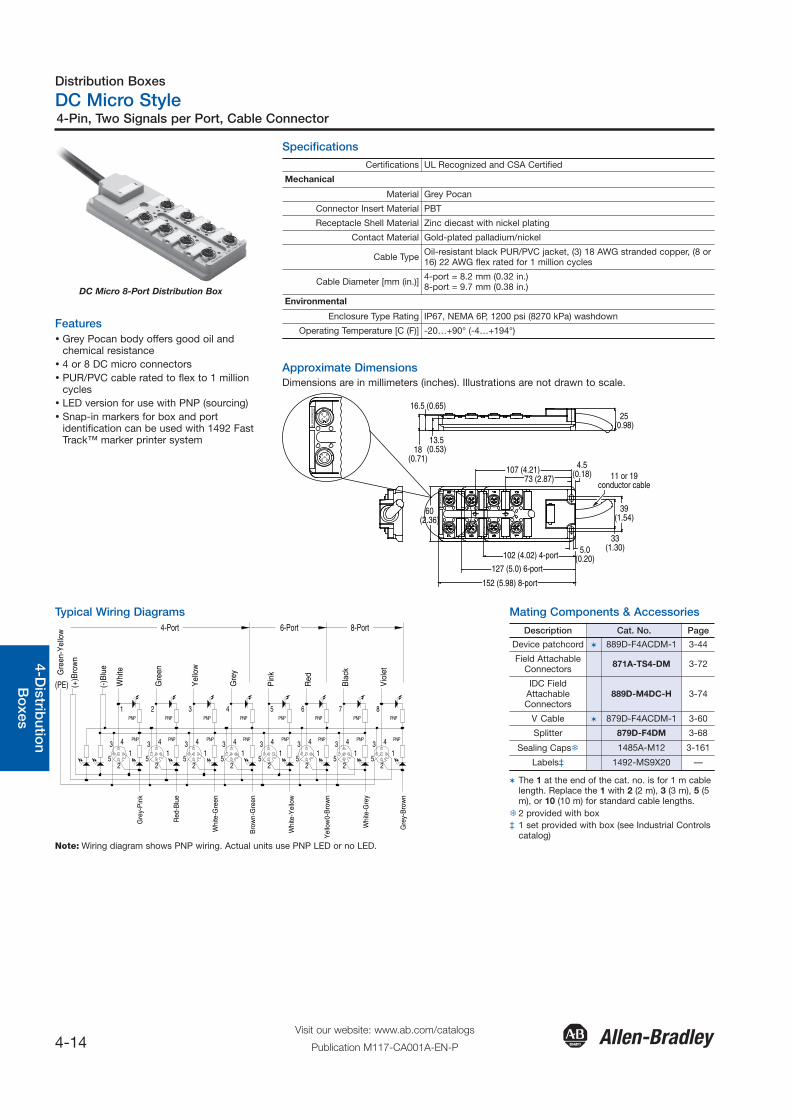
DC Micro 8-Port Distribution Box
Features� Grey Pocan body offers good oil and
chemical resistance� 4 or 8 DC micro connectors� PUR/PVC cable rated to flex to 1 million
cycles� LED version for use with PNP (sourcing)� Snap-in markers for box and port
identification can be used with 1492 FastTrack™ marker printer system
Specifications
Certifications UL Recognized and CSA Certified
Mechanical
Material Grey Pocan
Connector Insert Material PBT
Receptacle Shell Material Zinc diecast with nickel plating
Contact Material Gold-plated palladium/nickel
Cable Type Oil-resistant black PUR/PVC jacket, (3) 18 AWG stranded copper, (8 or16) 22 AWG flex rated for 1 million cycles
Cable Diameter [mm (in.)] 4-port = 8.2 mm (0.32 in.)8-port = 9.7 mm (0.38 in.)
Environmental
Enclosure Type Rating IP67, NEMA 6P, 1200 psi (8270 kPa) washdown
Operating Temperature [C (F)] -20…+90° (-4…+194°)
Approximate DimensionsDimensions are in millimeters (inches). Illustrations are not drawn to scale.
60(2.36)
107 (4.21)73 (2.87)
39(1.54)
4.5(0.18)
25(0.98)
11 or 19conductor cable
33(1.30)
102 (4.02) 4-port
127 (5.0) 6-port
152 (5.98) 8-port
13.5(0.53)
16.5 (0.65)
18(0.71)
-
5.0(0.20)
ALLE
N-B
RAD
LEY
ALLE
N-B
RAD
LEY
Typical Wiring Diagrams
51
3
1
4
51
3 4
2
51
51
3 4
3
3 4
4
51
5
3 4
5
3
6
15
15
134 4
7
3 4
8
2 2 2 2 2 2 2 2
4-Port
Gre
en-Y
ello
w
(+)B
row
n
(-)B
lue
Whi
te
Gre
en
(PE)
PNP
Yel
low
Gre
y
Pin
k
Red
Bla
ck
Vio
let
6-Port 8-Port
PNP
PNP
PNP
PNP
PNP
PNP
PNP
PNP
PNP
PNP
PNP
PNP
PNP
PNP
PNP
Gre
y-P
ink
Red
-Blu
e
Whi
te-G
reen
Bro
wn-
Gre
en
Whi
te-Y
ello
w
Yel
low
0-B
row
n
Whi
te-G
rey
Gre
y-B
row
n
Note: Wiring diagram shows PNP wiring. Actual units use PNP LED or no LED.
Mating Components & Accessories
Description Cat. No. Page
Device patchcord � 889D-F4ACDM-1 3-44
Field AttachableConnectors 871A-TS4-DM 3-72
IDC FieldAttachableConnectors
889D-M4DC-H 3-74
V Cable � 879D-F4ACDM-1 3-60
Splitter 879D-F4DM 3-68
Sealing Caps� 1485A-M12 3-161
Labels‡ 1492-MS9X20 —
� The 1 at the end of the cat. no. is for 1 m cablelength. Replace the 1 with 2 (2 m), 3 (3 m), 5 (5m), or 10 (10 m) for standard cable lengths.
� 2 provided with box‡ 1 set provided with box (see Industrial Controls
catalog)
Distribution Boxes
DC Micro Style
4-15Visit our website: www.ab.com/catalogs
Publication M117-CA001A-EN-P
4-Pin, Two Signals per Port, Cable Connector
Gen
eral
Qui
ck S
elec
tion
Intr
od
uctio
n3-
Co
nnec
tion
Sys
tem
s4-
Dis
trib
utio
nB
oxe
sS
afet
yC
onn
ectio
nN
etw
ork
Med
ia
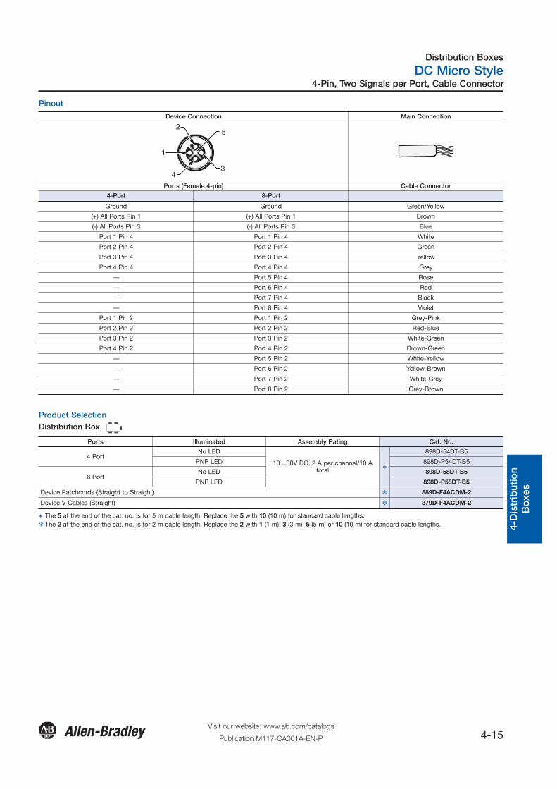
Pinout
Product SelectionDistribution Box
Device Connection Main Connection
5
4 3
1
2
Ports (Female 4-pin) Cable Connector
4-Port 8-Port
Ground Ground Green/Yellow
(+) All Ports Pin 1 (+) All Ports Pin 1 Brown
(-) All Ports Pin 3 (-) All Ports Pin 3 Blue
Port 1 Pin 4 Port 1 Pin 4 White
Port 2 Pin 4 Port 2 Pin 4 Green
Port 3 Pin 4 Port 3 Pin 4 Yellow
Port 4 Pin 4 Port 4 Pin 4 Grey
— Port 5 Pin 4 Rose
— Port 6 Pin 4 Red
— Port 7 Pin 4 Black
— Port 8 Pin 4 Violet
Port 1 Pin 2 Port 1 Pin 2 Grey-Pink
Port 2 Pin 2 Port 2 Pin 2 Red-Blue
Port 3 Pin 2 Port 3 Pin 2 White-Green
Port 4 Pin 2 Port 4 Pin 2 Brown-Green
— Port 5 Pin 2 White-Yellow
— Port 6 Pin 2 Yellow-Brown
— Port 7 Pin 2 White-Grey
— Port 8 Pin 2 Grey-Brown
Ports Illuminated Assembly Rating Cat. No.
4 PortNo LED
10…30V DC, 2 A per channel/10 Atotal �
898D-54DT-B5
PNP LED 898D-P54DT-B5
8 PortNo LED 898D-58DT-B5
PNP LED 898D-P58DT-B5
Device Patchcords (Straight to Straight) � 889D-F4ACDM-2
Device V-Cables (Straight) � 879D-F4ACDM-2
� The 5 at the end of the cat. no. is for 5 m cable length. Replace the 5 with 10 (10 m) for standard cable lengths. � The 2 at the end of the cat. no. is for 2 m cable length. Replace the 2 with 1 (1 m), 3 (3 m), 5 (5 m) or 10 (10 m) for standard cable lengths.
Distribution Boxes
DC Micro Style
4-16Visit our website: www.ab.com/catalogs
Publication M117-CA001A-EN-P
4-Pin, One Signal per Port, Terminal Block Connector
General
Quick S
election
Introd
uction
3-Co
nnection
System
s4-D
istributio
nB
oxes
Safety
Co
nnection
Netw
ork M
edia
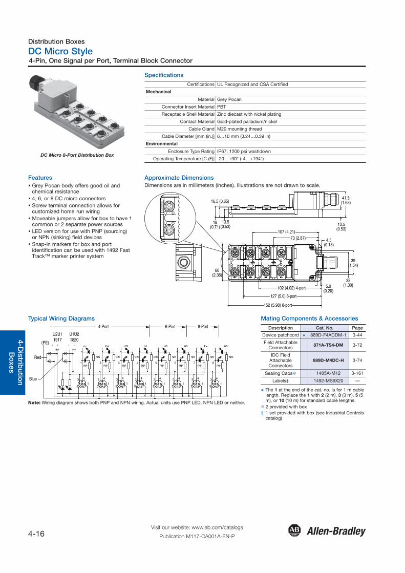
DC Micro 8-Port Distribution Box
Features� Grey Pocan body offers good oil and
chemical resistance� 4, 6, or 8 DC micro connectors� Screw terminal connection allows for
customized home run wiring� Moveable jumpers allow for box to have 1
common or 2 separate power sources� LED version for use with PNP (sourcing)
or NPN (sinking) field devices� Snap-in markers for box and port
identification can be used with 1492 FastTrack™ marker printer system
Specifications
Typical Wiring Diagrams
Certifications UL Recognized and CSA Certified
Mechanical
Material Grey Pocan
Connector Insert Material PBT
Receptacle Shell Material Zinc diecast with nickel plating
Contact Material Gold-plated palladium/nickel
Cable Gland M20 mounting thread
Cable Diameter [mm (in.)] 6…10 mm (0.24…0.39 in)
Environmental
Enclosure Type Rating IP67; 1200 psi washdown
Operating Temperature [C (F)] -20…+90° (-4…+194°)
Blue
-- --
3
5
4
1
1
5
31
4
5
3 4
2 3
15
3 4
15
3
4 5
1
4
5
3 4
1
6
4
5
31
5
31
4
7 8
4-Port
1 2
(PE)
NPN
3 4 5 6 7 8
6-Port 8-Port
PNP
NPN
PNP
NPN
PNP
NPN
PNP
NPN
PNP
NPN
PNP
NPN
PNP
NPN
PNP
++
1917U2U1
++
1820U1U2
Red
Note: Wiring diagram shows both PNP and NPN wiring. Actual units use PNP LED, NPN LED or neither.
Approximate DimensionsDimensions are in millimeters (inches). Illustrations are not drawn to scale.
107 (4.21)73 (2.87) 4.5
(0.18)
41.5(1.63)
33(1.30)5.0
(0.20)
ALLE
N-B
RAD
LEY
13.5(0.53)
16.5 (0.65)
18(0.71)
ALLE
N-B
RAD
LEY
13.5(0.53)
39(1.54)
898D
-54P
T-T
B
60(2.36)
102 (4.02) 4-port
127 (5.0) 6-port
152 (5.98) 8-port
Mating Components & Accessories
Description Cat. No. Page
Device patchcord � 889D-F4ACDM-1 3-44
Field AttachableConnectors 871A-TS4-DM 3-72
IDC FieldAttachableConnectors
889D-M4DC-H 3-74
Sealing Caps� 1485A-M12 3-161
Labels‡ 1492-MS9X20 —
� The 1 at the end of the cat. no. is for 1 m cablelength. Replace the 1 with 2 (2 m), 3 (3 m), 5 (5m), or 10 (10 m) for standard cable lengths.
� 2 provided with box‡ 1 set provided with box (see Industrial Controls
catalog)
Distribution Boxes
DC Micro Style
4-17Visit our website: www.ab.com/catalogs
Publication M117-CA001A-EN-P
4-Pin, One Signal per Port, Terminal Block Connector
Gen
eral
Qui
ck S
elec
tion
Intr
od
uctio
n3-
Co
nnec
tion
Sys
tem
s4-
Dis
trib
utio
nB
oxe
sS
afet
yC
onn
ectio
nN
etw
ork
Med
ia
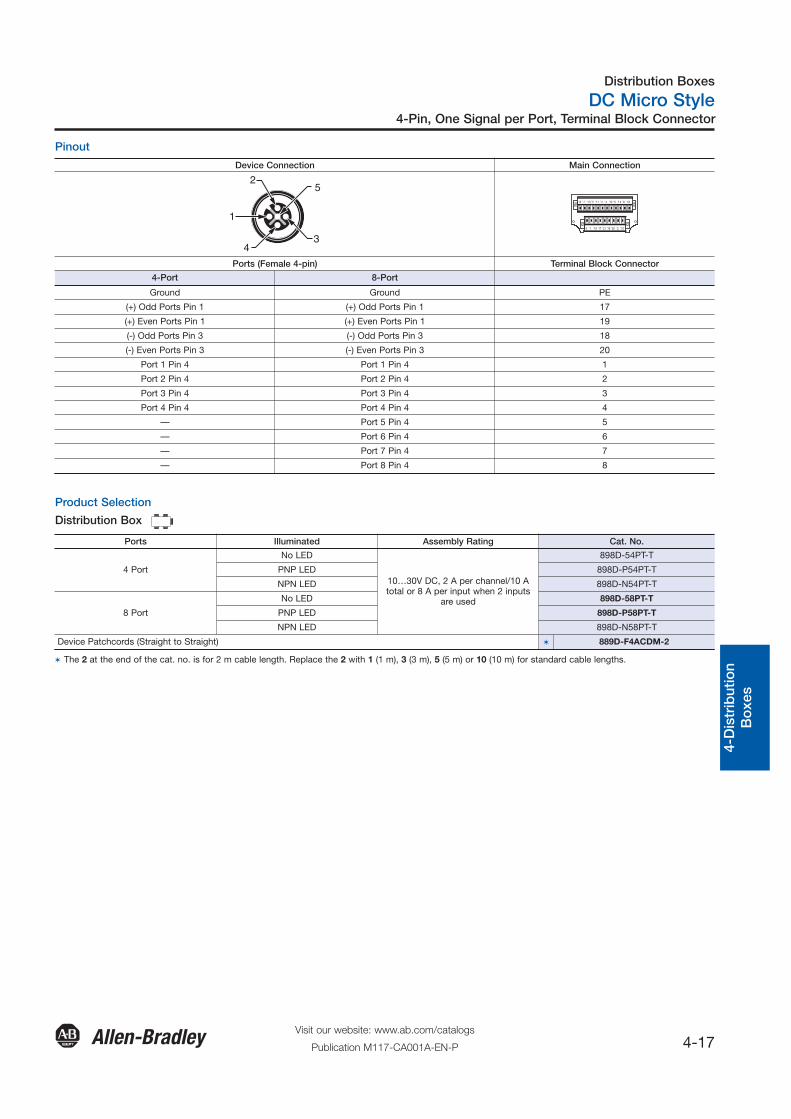
Pinout
Product Selection
Distribution Box
Device Connection Main Connection
5
4 3
1
2
15 7 13 5 11 3 4 12 6 14 8 16
9 1 19 17 21 18 20 2 10
Ports (Female 4-pin) Terminal Block Connector
4-Port 8-Port
Ground Ground PE
(+) Odd Ports Pin 1 (+) Odd Ports Pin 1 17
(+) Even Ports Pin 1 (+) Even Ports Pin 1 19
(-) Odd Ports Pin 3 (-) Odd Ports Pin 3 18
(-) Even Ports Pin 3 (-) Even Ports Pin 3 20
Port 1 Pin 4 Port 1 Pin 4 1
Port 2 Pin 4 Port 2 Pin 4 2
Port 3 Pin 4 Port 3 Pin 4 3
Port 4 Pin 4 Port 4 Pin 4 4
— Port 5 Pin 4 5
— Port 6 Pin 4 6
— Port 7 Pin 4 7
— Port 8 Pin 4 8
Ports Illuminated Assembly Rating Cat. No.
4 Port
No LED
10…30V DC, 2 A per channel/10 Atotal or 8 A per input when 2 inputs
are used
898D-54PT-T
PNP LED 898D-P54PT-T
NPN LED 898D-N54PT-T
8 Port
No LED 898D-58PT-T
PNP LED 898D-P58PT-T
NPN LED 898D-N58PT-T
Device Patchcords (Straight to Straight) � 889D-F4ACDM-2
� The 2 at the end of the cat. no. is for 2 m cable length. Replace the 2 with 1 (1 m), 3 (3 m), 5 (5 m) or 10 (10 m) for standard cable lengths.
Distribution Boxes
DC Micro Style
4-18Visit our website: www.ab.com/catalogs
Publication M117-CA001A-EN-P
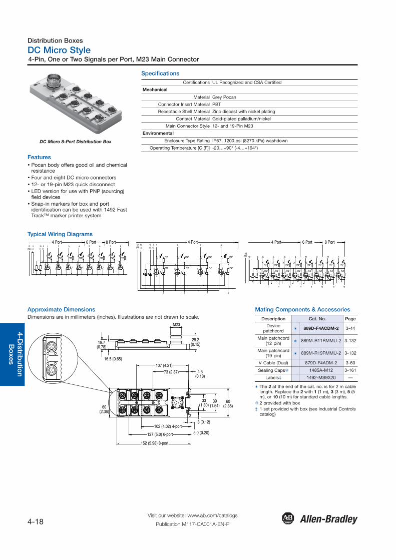
4-Pin, One or Two Signals per Port, M23 Main Connector
General
Quick S
election
Introd
uction
3-Co
nnection
System
s4-D
istributio
nB
oxes
Safety
Co
nnection
Netw
ork M
edia
DC Micro 8-Port Distribution Box
Features� Pocan body offers good oil and chemical
resistance� Four and eight DC micro connectors� 12- or 19-pin M23 quick disconnect� LED version for use with PNP (sourcing)
field devices� Snap-in markers for box and port
identification can be used with 1492 FastTrack™ marker printer system
Specifications
Typical Wiring Diagrams
Certifications UL Recognized and CSA Certified
Mechanical
Material Grey Pocan
Connector Insert Material PBT
Receptacle Shell Material Zinc diecast with nickel plating
Contact Material Gold-plated palladium/nickel
Main Connector Style 12- and 19-Pin M23
Environmental
Enclosure Type Rating IP67, 1200 psi (8270 kPa) washdown
Operating Temperature [C (F)] -20…+90° (-4…+194°)
3
5
41
5
3
PNP1 2
14
5
3 41
PNP PNP3
4
5
31
5
31
4
PNP4 5
PNP
3
5
41
5
3
PNP6 7
14
5
31
4
8PNP PNP
(-)1012
(PE)11(+)
19(-)
2 3 4 5 6 7 8
5
52
1
PNP
3 4
1
PNP
6 7 8
(PE)12
(+)11
(-)(-)10 9 1 2 3 4
2
3
51
4 PNP
PNP1
3
52
1
PNP4
PNP1
PNP1
2
3
51
PNP4
1
51
3
1
11217316515619
4
51
3 4
2
12(PE)
51
51
3 4
3
3 4
4
51
5
3 4
5
3
6
15
15
134 4
7
3 4
8
2 2 2 2 2 2 2 2
PNPPNP PNP PNP PNP PNP PNP PNP
PNP PNP PNP PNP PNP PNP PNP PNP
181013914847
4 Port 6 Port 8 Port 4 Port 4 Port 6 Port 8 Port
Approximate DimensionsDimensions are in millimeters (inches). Illustrations are not drawn to scale.
73 (2.87)107 (4.21)
4.5(0.18)
5.0 (0.20)
ALLE
N-BR
ADLE
Y
16.5 (0.65)
898D
-54P
T-M
12 B
19.7(0.78)
M23
3 (0.12)
29.2(0.15)
33(1.30)
39(1.54)
60(2.36)60
(2.36)
102 (4.02) 4-port
127 (5.0) 6-port
152 (5.98) 8-port
ALLE
N-B
RAD
LEY
Mating Components & Accessories
Description Cat. No. Page
Devicepatchcord � 889D-F4ACDM-2 3-44
Main patchcord(12 pin) � 889M-R11RMMU-2 3-132
Main patchcord(19 pin) � 889M-R19RMMU-2 3-132
V Cable (Dual) 879D-F4ADM-2 3-60
Sealing Caps� 1485A-M12 3-161
Labels‡ 1492-MS9X20 —
� The 2 at the end of the cat. no. is for 2 m cablelength. Replace the 2 with 1 (1 m), 3 (3 m), 5 (5m), or 10 (10 m) for standard cable lengths.
� 2 provided with box‡ 1 set provided with box (see Industrial Controls
catalog)
Distribution Boxes
DC Micro Style
4-19Visit our website: www.ab.com/catalogs
Publication M117-CA001A-EN-P
4-Pin, One or Two Signals per Port, M23 Main Connector
Gen
eral
Qui
ck S
elec
tion
Intr
od
uctio
n3-
Co
nnec
tion
Sys
tem
s4-
Dis
trib
utio
nB
oxe
sS
afet
yC
onn
ectio
nN
etw
ork
Med
ia
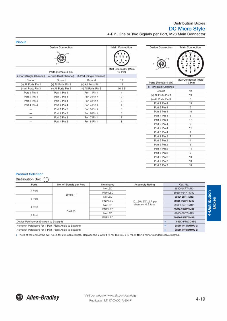
Pinout
Device Connection Main Connection
5
4 3
1
2
2
3
45
6
1
11
10
98
712
Ports (Female 4-pin)M23 Connector (Male
12 Pin)
4-Port (Single Channel) 4-Port (Dual Channel) 8-Port (Single Channel)
Ground Ground Ground 12
(+) All Ports Pin 1 (+) All Ports Pin 2 (+) All Ports Pin 1 11
(-) All Ports Pin 3 (-) All Ports Pin 4 (-) All Ports Pin 3 10 & 9
Port 1 Pin 4 Port 1 Pin 4 Port 1 Pin 4 1
Port 2 Pin 4 Port 2 Pin 4 Port 2 Pin 4 2
Port 3 Pin 4 Port 3 Pin 4 Port 3 Pin 4 3
Port 4 Pin 4 Port 4 Pin 4 Port 4 Pin 4 4
— Port 1 Pin 2 Port 5 Pin 4 5
— Port 2 Pin 2 Port 6 Pin 4 6
— Port 3 Pin 2 Port 7 Pin 4 7
— Port 4 Pin 2 Port 8 Pin 4 8
Device Connection Main Connection
5
4 3
1
2 2
3
456
11110
9
87
12
1813
1416
1719
15
Ports (Female 4-pin)M23 Connector (Male
19 Pin)
8-Port (Dual Channel)
Ground 12
(+) All Ports Pin 1 19
(-) All Ports Pin 3 6
Port 1 Pin 4 15
Port 2 Pin 4 5
Port 3 Pin 4 16
Port 4 Pin 4 3
Port 5 Pin 4 17
Port 6 Pin 4 2
Port 7 Pin 4 11
Port 8 Pin 4 1
Port 1 Pin 2 7
Port 2 Pin 2 4
Port 3 Pin 2 8
Port 4 Pin 2 14
Port 5 Pin 2 9
Port 6 Pin 2 13
Port 7 Pin 2 10
Port 8 Pin 2 18
Product Selection
Distribution Box
Ports No. of Signals per Port Illuminated Assembly Rating Cat. No.
4 Port
Single (1)
No LED
10…30V DC, 2 A perchannel/10 A total
898D-54PT-M12
PNP LED 898D-P54PT-M12
8 PortNo LED 898D-58PT-M12
PNP LED 898D-P58PT-M12
4 Port
Dual (2)
No LED 898D-54DT-M12
PNP LED 898D-P54DT-M12
8 PortNo LED 898D-58DT-M19
PNP LED 898D-P58DT-M19
Device Patchcords (Straight to Straight) � 889D-F4ACDM-2
Homerun Patchcord for 4-Port (Right Angle to Straight) � 889M-R11RMMU-2
Homerun Patchcord for 8-Port (Right Angle to Straight) � 889M-R19RMMU-2
� The 2 at the end of the cat. no. is for 2 m cable length. Replace the 2 with 1 (1 m), 3 (3 m), 5 (5 m) or 10 (10 m) for standard cable lengths.
12.5(0.50)
5.5 (0.22) dia.mounting holes (4 places)
31
42
49.2 (1.94)3-pole femreceptacle(4 places)
98.4 (3.88)
47.8(1.88)
73.0(2.88)
60.3(2.38)
75
86
31
42
31
42
5
6
98.4 (3.88)44.5 (1.75) 49.2 (1.94)
9-pole malereceptacle
88.9 (3.5)
47.8(1.88)
73.0(2.88)
60.3(2.38)
5.5 (0.22) dia.mounting holes (4 places)
3-pole femreceptacle(6 places) 12.5
(0.50) 5.5 (0.22) dia.mounting holes (4 places)
3-pole femreceptacle(8 places)
47.8(1.88)
73.0(2.88)
60.3(2.38)
12-pole malereceptacle
12.5(0.50)
49.2 (1.94)187.3 (7.38)
Distribution Boxes
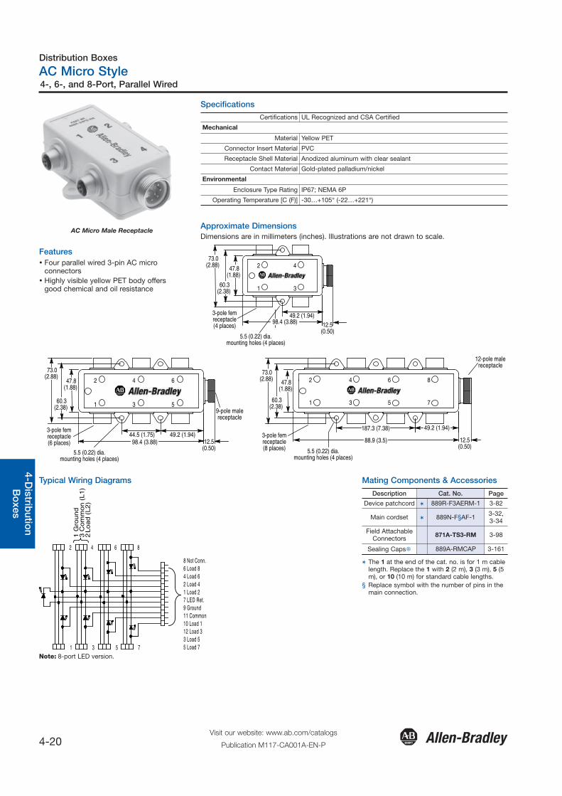
AC Micro Style
4-20Visit our website: www.ab.com/catalogs
Publication M117-CA001A-EN-P
4-, 6-, and 8-Port, Parallel Wired
General
Quick S
election
Introd
uction
3-Co
nnection
System
s4-D
istributio
nB
oxes
Safety
Co
nnection
Netw
ork M
edia
AC Micro Male Receptacle
Features� Four parallel wired 3-pin AC micro
connectors� Highly visible yellow PET body offers
good chemical and oil resistance
Specifications
Approximate DimensionsDimensions are in millimeters (inches). Illustrations are not drawn to scale.
Certifications UL Recognized and CSA Certified
Mechanical
Material Yellow PET
Connector Insert Material PVC
Receptacle Shell Material Anodized aluminum with clear sealant
Contact Material Gold-plated palladium/nickel
Environmental
Enclosure Type Rating IP67; NEMA 6P
Operating Temperature [C (F)] -30…+105° (-22…+221°)
Typical Wiring Diagrams
75
86
31
42
8 Not Conn.6 Load 84 Load 62 Load 41 Load 27 LED Ret.9 Ground11 Common10 Load 112 Load 33 Load 55 Load 7
1 G
rou
nd
3 C
om
mo
n (
L1
)2
Lo
ad
(L
2)
Note: 8-port LED version.
Mating Components & Accessories
Description Cat. No. Page
Device patchcord � 889R-F3AERM-1 3-82
Main cordset � 889N-F§AF-1 3-32,3-34
Field AttachableConnectors 871A-TS3-RM 3-98
Sealing Caps� 889A-RMCAP 3-161
� The 1 at the end of the cat. no. is for 1 m cablelength. Replace the 1 with 2 (2 m), 3 (3 m), 5 (5m), or 10 (10 m) for standard cable lengths.
§ Replace symbol with the number of pins in themain connection.

Distribution Boxes
AC Micro Style
4-21Visit our website: www.ab.com/catalogs
Publication M117-CA001A-EN-P
4-, 6-, and 8-Port, Parallel Wired
Gen
eral
Qui
ck S
elec
tion
Intr
od
uctio
n3-
Co
nnec
tion
Sys
tem
s4-
Dis
trib
utio
nB
oxe
sS
afet
yC
onn
ectio
nN
etw
ork
Med
ia
Pinout and Wiring Arrangement
2
1 3
Main Connection
4-Port 6-Port 8-Port
Wiring Arangement A B C D E F
Ports (3-pin ACMicro Female) 6-Pin Mini Male 7-Pin Mini Male 8-Pin Mini Male 9-Pin Mini Male 10-Pin Mini Male 12-Pin Mini Male
LED Return — Pin 1 — Pin 4 — Pin 7
All Ports Pin 3 (L1) Pin 1 Pin 3 Pin 5 Pin 5 Pin 10 Pin 11
All Ports Pin 1 (GND) Pin 3 Pin 7 Pin 7 Pin 7 Pin 8 Pin 9
Port 1 Pin 2 (L2) Pin 2 Pin 4 Pin 6 Pin 6 Pin 7 Pin 10
Port 2 Pin 2 (L2) Pin 4 Pin 5 Pin 1 Pin 1 Pin 1 Pin 1
Port 3 Pin 2 (L2) Pin 5 Pin 2 Pin 4 Pin 9 Pin 9 Pin 12
Port 4 Pin 2 (L2) Pin 6 Pin 6 Pin 2 Pin 2 Pin 2 Pin 2
Port 5 Pin 2 (L2) — — Pin 3 Pin 8 Pin 3 Pin 3
Port 6 Pin 2 (L2) — — Pin 8 Pin 3 Pin 4 Pin 4
Port 7 Pin 2 (L2) — — — — Pin 5 Pin 5
Port 8 Pin 2 (L2) — — — — Pin 6 Pin 6
No Connection — — — — — Pin 8
Product Selection3-Pin Distribution Boxes
No. of Ports Illuminated Assembly Rating Wiring Arrangement Cat. No.�
4 PortNo LED 300V, 3 A A 898R-34PS-N6
LED 120V, 3 A B 898R-L34PS-N7
6 PortNo LED 300V, 3 A C 898R-36PS-N8
LED 120V, 3 A D 898R-L36PS-N9
8 PortNo LED 300V, 3 A E 898R-38PS-N10
LED 120V, 3 A F 898R-L38PS-N12
Device Patchcords (Straight to Straight) 889R-F3AERM-2
Main Cordset (Straight to Conductor) 889N-F§AF-1
� The 2 at the end of the cat. no. is for 2 m cable length. Replace the 2 with 1 (1 m), 3 (3 m), 5 (5 m), or 10 (10 m) for standard cable lengths. § Replace symbol with the number of pins in the main connection.
Distribution Boxes
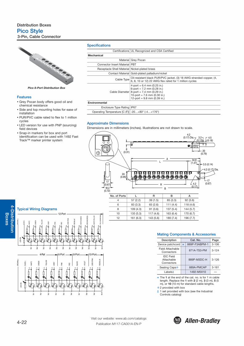
Pico Style
4-22Visit our website: www.ab.com/catalogs
Publication M117-CA001A-EN-P
3-Pin, Cable Connector
General
Quick S
election
Introd
uction
3-Co
nnection
System
s4-D
istributio
nB
oxes
Safety
Co
nnection
Netw
ork M
edia
Pico 8-Port Distribution Box
Features� Grey Pocan body offers good oil and
chemical resistance� Side and top mounting holes for ease of
installation� PUR/PVC cable rated to flex to 1 million
cycles� LED version for use with PNP (sourcing)
field devices� Snap-in markers for box and port
identification can be used with 1492 FastTrack™ marker printer system
Specifications
Certifications UL Recognized and CSA Certified
Mechanical
Material Grey Pocan
Connector Insert Material PBT
Receptacle Shell Material Nickel-plated brass
Contact Material Gold-plated palladium/nickel
Cable Type Oil-resistant black PUR/PVC jacket, (3) 18 AWG stranded copper, (4,6, 8, 10 or 12) 22 AWG flex rated for 1 million cycles
Cable Diameter
4-port = 6.4 mm (0.25 in.)6-port = 7.2 mm (0.28 in.)8-port = 7.4 mm (0.29 in.)10-port = 7.6 mm (0.30 in.)12-port = 9.8 mm (0.39 in.)
Environmental
Enclosure Type Rating IP67
Operating Temperature [C (F)] -20…+80° (-4…+176°)
Approximate DimensionsDimensions are in millimeters (inches). Illustrations are not drawn to scale.
412
34.8(1.37)
ALLEN-BRADLEY898P-P34PT-B5
12 1 10 424
(0.95)
AL
4.2 (0.17) Dia.
17(0.67)
8(0.31)
4.5(0.18)
3.5 (0.14)
20(0.79)
3.2(0.13)
R
4.2(0.17) Dia.
4.2(0.17)
17(0.67)18.2
(0.72) B
13
A B
No. of Ports L R B A
4 57 (2.2) 39 (1.5) 85 (3.3) 92 (3.6)
6 83 (3.3) 65 (2.6) 111 (4.4) 118 (4.6)
8 109 (4.3) 91 (3.6) 137 (5.4) 144 (5.7)
10 135 (5.3) 117 (4.6) 163 (6.4) 170 (6.7)
12 161 (6.3) 143 (5.6) 189 (7.4) 196 (7.7)
Mating Components & Accessories
Description Cat. No. Page
Device patchcord � 889P-F3ABPM-1 3-106
Field AttachableConnectors 871A-TS3-PM 3-124
IDC FieldAttachableConnectors
889P-M3DC-H 3-126
Sealing Caps� 889A-PMCAP 3-161
Labels‡ 1492-M5X10 —
� The 1 at the end of the cat. no. is for 1 m cablelength. Replace the 1 with 2 (2 m), 3 (3 m), 5 (5m), or 10 (10 m) for standard cable lengths.
� 2 provided with box‡ 1 set provided with box (see the Industrial
Controls catalog)
Typical Wiring Diagrams
4-Port 6-Port 8-Port 10-Port
12-Port
LED
-GN
3
4
Bu1
Bu2
31
Bu3
31 1
4 4
Bu4
3 1
Bu5
3 31
4 4 4
Bu8
Bu6
1 3
Bu7
1 3
4 4
Bu9
31
Bu10
31 1
4 4
BRO
WN
(+)
BLU
E(-)
AW
HIT
E
AG
REE
N
AYE
LLO
W
AG
REY
A A
PIN
K
GR
EY/P
INK
A
RED
AR
ED/B
LUE
BRO
WN
/GR
EEN
WH
ITE/
GR
EEN
A A
Bu12
Bu11
3
4
1 3
4
1
YELL
OW
/BR
OW
N
WH
ITE/
YELL
OW
A A
BLU
E(-)
BRO
WN
(+)
3 1
4
WH
ITE
4
3 1
4
3 1 3
4
1 13
4
3
4
1 3
4 4
31 1
A A A A A A A A
GR
EEN
YELL
OW
GR
EY
PIN
K
RED
BLAC
K
VIO
LET
LED
-GN
Bu1
Bu2
Bu3
Bu4
Bu5
Bu6
Bu7
Bu8
4
313
Bu9
4
1
Bu10
A
GR
EY/P
INK
A
RED
/BLU
E

Distribution Boxes
Pico Style
4-23Visit our website: www.ab.com/catalogs
Publication M117-CA001A-EN-P
3-Pin, Cable Connector
Gen
eral
Qui
ck S
elec
tion
Intr
od
uctio
n3-
Co
nnec
tion
Sys
tem
s4-
Dis
trib
utio
nB
oxe
sS
afet
yC
onn
ectio
nN
etw
ork
Med
ia
Pinout
Device Connection Main Connection
3 1
4
Ports (Female 3 pin) Cable
4-Port 6-Port 8-Port 10-Port 12-Port
Ground Ground Ground Ground Ground Green/Yellow
(+) All Ports Pin 1 (+) All Ports Pin 1 (+) All Ports Pin 1 (+) All Ports Pin 1 (+) All Ports Pin 1 Brown
(-) All Ports Pin 3 (-) All Ports Pin 3 (-) All Ports Pin 3 (-) All Ports Pin 3 (-) All Ports Pin 3 Blue
Port 1 Pin 4 Port 1 Pin 4 Port 1 Pin 4 Port 1 Pin 4 Port 1 Pin 4 White
Port 2 Pin 4 Port 2 Pin 4 Port 2 Pin 4 Port 2 Pin 4 Port 2 Pin 4 Green
Port 3 Pin 4 Port 3 Pin 4 Port 3 Pin 4 Port 3 Pin 4 Port 3 Pin 4 Yellow
Port 4 Pin 4 Port 4 Pin 4 Port 4 Pin 4 Port 4 Pin 4 Port 4 Pin 4 Grey
— Port 5 Pin 4 Port 5 Pin 4 Port 5 Pin 4 Port 5 Pin 4 Rose
— Port 6 Pin 4 Port 6 Pin 4 Port 6 Pin 4 Port 6 Pin 4 Red
— — Port 7 Pin 4 Port 7 Pin 4 — Black
— — Port 8 Pin 4 Port 8 Pin 4 — Violet
— — — Port 9 Pin 4 Port 7 Pin 4 Grey/Pink
— — — Port 10 Pin 4 Port 8 Pin 4 Red/Glue
— — — — Port 9 Pin 4 White/Green
— — — — Port 10 Pin 4 Brown/Green
— — — — Port 11 Pin 4 White/Yellow
— — — — Port 12 Pin 4 Yellow/Brown
Product Selection3-Pin Single Output, Distribution Boxes
No. of Ports Illuminated Assembly Rating Cat. No.
4-Port
PNP LED 10…30V DC, 2 A per channel/6 Atotal
� 898P-P34PT-B5
6-Port � 898P-P36PT-B5
8-Port � 898P-P38PT-B5
10-Port � 898P-P310PT-B5
12-Port � 898P-P312PT-B5
Device Patchcord (3-pin straight to straight) � 889P-F3ABPM-5
� The 5 at the end of the cat. no. is for 5 m cable length. Replace the 5 with 10 (10 m) for standard lengths.� The 5 at the end of the cat. no. is for 5 m cable length. Replace the 5 with 1 (1 m), 2 (2 m), 3 (3 m), or 10 (10 m) for standard lengths.
Distribution Boxes
Pico Style
4-24Visit our website: www.ab.com/catalogs
Publication M117-CA001A-EN-P
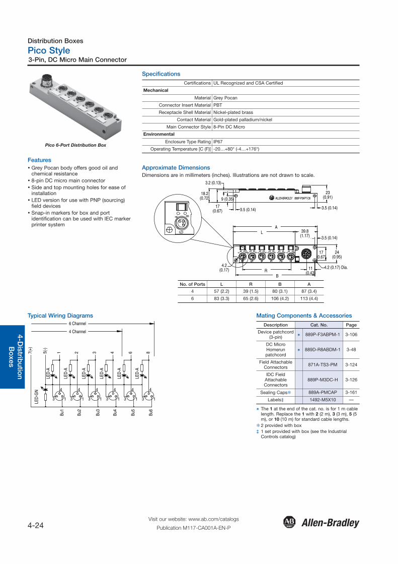
3-Pin, DC Micro Main Connector
General
Quick S
election
Introd
uction
3-Co
nnection
System
s4-D
istributio
nB
oxes
Safety
Co
nnection
Netw
ork M
edia
Pico 6-Port Distribution Box
Features� Grey Pocan body offers good oil and
chemical resistance� 8-pin DC micro main connector� Side and top mounting holes for ease of
installation� LED version for use with PNP (sourcing)
field devices� Snap-in markers for box and port
identification can be used with IEC markerprinter system
Specifications
Certifications UL Recognized and CSA Certified
Mechanical
Material Grey Pocan
Connector Insert Material PBT
Receptacle Shell Material Nickel-plated brass
Contact Material Gold-plated palladium/nickel
Main Connector Style 8-Pin DC Micro
Environmental
Enclosure Type Rating IP67
Operating Temperature [C (F)] -20…+80° (-4…+176°)
Approximate DimensionsDimensions are in millimeters (inches). Illustrations are not drawn to scale.
17(0.67)
3.2 (0.13)
4.2(0.17) 4.2 (0.17) Dia.11
(0.43)
9 (0.35)
3.5 (0.14)
R
18.2(0.72)
B
ALLEN-BRADLEY 898P-P34PT-D8
3.5 (0.14)
23(0.91)
AL
3.5 (0.14)
17(0.67)
24(0.95)
39.8(1.17)
A B A B A B A B A B A B
413
A B
No. of Ports L R B A
4 57 (2.2) 39 (1.5) 80 (3.1) 87 (3.4)
6 83 (3.3) 65 (2.6) 106 (4.2) 113 (4.4)
Mating Components & Accessories
Description Cat. No. Page
Device patchcord(3-pin) � 889P-F3ABPM-1 3-106
DC MicroHomerunpatchcord
� 889D-R8ABDM-1 3-48
Field AttachableConnectors 871A-TS3-PM 3-124
IDC FieldAttachableConnectors
889P-M3DC-H 3-126
Sealing Caps� 889A-PMCAP 3-161
Labels‡ 1492-M5X10 —
� The 1 at the end of the cat. no. is for 1 m cablelength. Replace the 1 with 2 (2 m), 3 (3 m), 5 (5m), or 10 (10 m) for standard cable lengths.
� 2 provided with box‡ 1 set provided with box (see the Industrial
Controls catalog)
Typical Wiring Diagrams
5(-)
7(+)
3 1
4
4
4 Channel
6 Channel
4
3 1
4
3 1 3
4
1 13
4
3
4
1
321 6 8
LED
-GN
Bu1
Bu2
Bu3
Bu4
Bu5
Bu6
LED
-A
LED
-A
LED
-A
LED
-A
LED
-A
LED
-A
Distribution Boxes
Pico Style
4-25Visit our website: www.ab.com/catalogs
Publication M117-CA001A-EN-P
3-Pin, DC Micro Main Connector
Gen
eral
Qui
ck S
elec
tion
Intr
od
uctio
n3-
Co
nnec
tion
Sys
tem
s4-
Dis
trib
utio
nB
oxe
sS
afet
yC
onn
ectio
nN
etw
ork
Med
ia
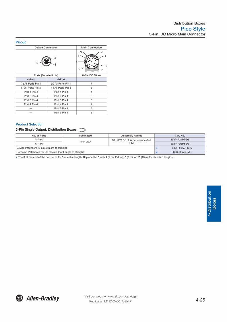
Pinout
Device Connection Main Connection
3 1
4
5 67
8
4
31
2
Ports (Female 3 pin) 8-Pin DC Micro
4-Port 6-Port
(+) All Ports Pin 1 (+) All Ports Pin 1 7
(-) All Ports Pin 3 (-) All Ports Pin 3 5
Port 1 Pin 4 Port 1 Pin 4 1
Port 2 Pin 4 Port 2 Pin 4 2
Port 3 Pin 4 Port 3 Pin 4 3
Port 4 Pin 4 Port 4 Pin 4 4
— Port 5 Pin 4 6
— Port 6 Pin 4 8
Product Selection
3-Pin Single Output, Distribution Boxes
No. of Ports Illuminated Assembly Rating Cat. No.
4-PortPNP LED 10…30V DC, 2 A per channel/3 A
total898P-P34PT-D8
6-Port 898P-P36PT-D8
Device Patchcord (3-pin straight to straight) � 889P-F3ABPM-5
Homerun Patchcord for D8 models (right angle to straight) � 889D-R8ABDM-5
� The 5 at the end of the cat. no. is for 5 m cable length. Replace the 5 with 1 (1 m), 2 (2 m), 3 (3 m), or 10 (10 m) for standard lengths.
Distribution Boxes
IDC Style
4-26Visit our website: www.ab.com/catalogs
Publication M117-CA001A-EN-P
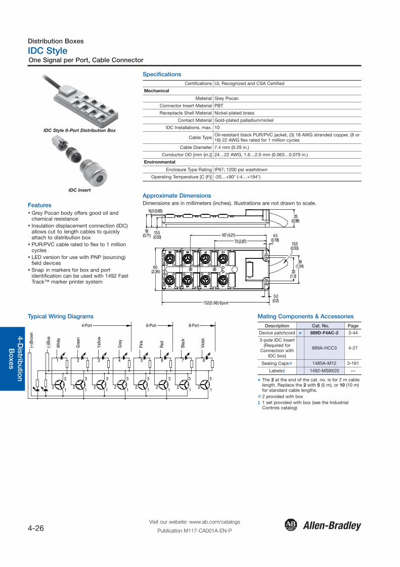
One Signal per Port, Cable Connector
General
Quick S
election
Introd
uction
3-Co
nnection
System
s4-D
istributio
nB
oxes
Safety
Co
nnection
Netw
ork M
edia
IDC Style 8-Port Distribution Box
IDC Insert
Features� Grey Pocan body offers good oil and
chemical resistance� Insulation displacement connection (IDC)
allows cut to length cables to quicklyattach to distribution box
� PUR/PVC cable rated to flex to 1 millioncycles
� LED version for use with PNP (sourcing)field devices
� Snap in markers for box and portidentification can be used with 1492 FastTrack™ marker printer system
Specifications
Approximate DimensionsDimensions are in millimeters (inches). Illustrations are not drawn to scale.
Certifications UL Recognized and CSA Certified
Mechanical
Material Grey Pocan
Connector Insert Material PBT
Receptacle Shell Material Nickel-plated brass
Contact Material Gold-plated palladium/nickel
IDC Installations, max. 10
Cable Type Oil-resistant black PUR/PVC jacket, (3) 18 AWG stranded copper, (8 or16) 22 AWG flex rated for 1 million cycles
Cable Diameter 7.4 mm (0.29 in.)
Conductor OD [mm (in.)] 24…22 AWG, 1.6…2.0 mm (0.063…0.079 in.)
Environmental
Enclosure Type Rating IP67; 1200 psi washdown
Operating Temperature [C (F)] -20…+90° (-4…+194°)
60(2.36)
39(1.54)
25(0.98)
898H
-58P
T-B5
BAl
len B
radle
y
1 231
2 3 12 3
31 2
12 3
31 2
12 3
31 2
152(5.98) 8 port
107 (4.21)73 (2.87)
4.5(0.18)
13.5(0.53)
33(1.3)
13.5 (0.53)
16.5 (0.65)
18 (0.71)
5.0(0.2)
Mating Components & AccessoriesTypical Wiring Diagrams4-Port
(+)B
row
n
(-)Bl
ue
Whi
te
Gre
en
Yello
w
Gre
y
Pink
Red
6-Port 8-Port
3
12
1111
3
2
33
22
3
221
21
3 3
21
3
1 2 3 4 5 6 7 8
Blac
k
Viol
et
Description Cat. No. Page
Device patchcord � 889D-F4AC-2 3-44
3-pole IDC Insert(Required for
Connection withIDC box)
889A-HCC3 4-27
Sealing Caps� 1485A-M12 3-161
Labels‡ 1492-MS9X20 —
� The 2 at the end of the cat. no. is for 2 m cablelength. Replace the 2 with 5 (5 m), or 10 (10 m)for standard cable lengths.
� 2 provided with box‡ 1 set provided with box (see the Industrial
Controls catalog)

Distribution Boxes
IDC Style
4-27Visit our website: www.ab.com/catalogs
Publication M117-CA001A-EN-P
One Signal per Port, Cable Connector
Gen
eral
Qui
ck S
elec
tion
Intr
od
uctio
n3-
Co
nnec
tion
Sys
tem
s4-
Dis
trib
utio
nB
oxe
sS
afet
yC
onn
ectio
nN
etw
ork
Med
ia
Pinout
Device Connection Main Connection
1
3
2
Ports (IDC) Cable Connector
8-Port
(+) All Ports Pin 1 Brown
(-) All Ports Pin 3 Blue
Port 1 Pin 2 White
Port 2 Pin 2 Green
Port 3 Pin 2 Yellow
Port 4 Pin 2 Grey
Port 5 Pin 2 Rose
Port 6 Pin 2 Red
Port 7 Pin 2 Black
Port 8 Pin 2 Violet
Product Selection3-Pin Single Output, Distribution Boxes
No. of Ports Illuminated Assembly Rating Cat. No.
8 Port No LED 10…30V DC, 2 A per channel/10 Atotal
� 898H-58PT-B5
8 Port PNP LED � 898H-P58PT-B5
Device Patchcord (3 pin straight to straight) 889A-HCC3
Device Patchcord (3 pin straight to straight) � 889D-F4AC-5
� The 5 at the end of the cat. no. is for 5 m cable length. Replace the 5 with 10 (10 m) for standard lengths.� The 5 at the end of the cat. no. is for 5 m cable length. Replace the 5 with 2 (2 m) or 10 (10 m) for standard lengths.
Distribution Boxes
Notes
4-28Visit our website: www.ab.com/catalogs
Publication M117-CA001A-EN-P
General
Quick S
election
Introd
uction
3-Co
nnection
System
s4-D
istributio
nB
oxes
Safety
Co
nnection
Netw
ork M
edia