Embed Size (px)
Citation preview

Power Supply and Media
Table of Contents
11-1Visit our website: www.ab.com/catalogs
Publication M117-CA001A-EN-P
Gen
eral
Qui
ck S
elec
tion
Intr
od
uctio
nC
onn
ectio
nS
yste
ms
11-P
ow
erS
upp
ly &
Med
iaS
afet
yC
onn
ectio
nN
etw
ork
Med
ia
Three-Phase Power Media
General Information
Three-Phase Power Cordsets & Patchcords — Trunk Cable ..............................................11-6
Three-Phase Power Cordsets & Patchcords — Drop Cable ................................................11-8
Three-Phase Power Tees & Reducer — 4-Pole ..................................................................11-10
Three-Phase Power Receptacles, Male & Female..............................................................11-12
Control Power MediaTrunk and Drop Cables ......................................................................................................11-14
T-Ports ................................................................................................................................11-16
Receptacles ........................................................................................................................11-17
Shorting Plugs ....................................................................................................................11-18
Three-Phase and Control Power MediaAccessories ........................................................................................................................11-19
Catalog Number Index ........................................................................ 12-1Power Supply .................................................................................... 11-20
Selection Criteria ..................................................................................................................11-2
Quick Selection Guide ..........................................................................................................11-4
Power Supply and Media
Note: The products in this chapter are all suitable for use with ArmorStart® Distributed MotorControllers. For product information, see the Industrial Controls catalog orwww.ab.com/catalogs.

Power Supply and Media
Selection Criteria
11-2Visit our website: www.ab.com/catalogs
Publication M117-CA001A-EN-P
General
Quick S
election
Introd
uction
Co
nnection
System
s11-P
ow
erS
upp
ly & M
edia
Safety
Co
nnection
Netw
ork M
edia
Description
� Reduce commissioning time� Plug and play design eliminates wiring
errors� Increased system design flexibility� No special tools required� Reduced labor costs
Control Power Media
� Cordsets: Cable with integral male orfemale connector at one end and flyingleads at the other
� Patchcords: Cable with integralconnector at each end (one male, onefemale)
Power Supplies
� Cordsets: Cable with integral male orfemale connector at one end and flyingleads at the otherAvailable in 2, 5, or 10 m lengths.
� Patchcords: Cable with integralconnector at each end (one male, onefemale)Available in 1, 2, 3, 5, or 10 m lengths.
The power media offers both three-phaseand control power cable systems ofcordsets, patchcords, receptacles, tees,reducers and accessories, to be used withthe ArmorStart Distributed Motor Controller.These cable system components allowquick connection of ArmorStart DistributedMotor Controllers, thereby reducinginstallation time. They provide forrepeatable, reliable connection of the three-phase and control power to the ArmorStartDistributed Motor Controller and motor, byproviding a plug and play environment thatalso avoids system mis-wiring.
Compared to the traditional conduitinstallations, with power media you profitand benefit from:
The control power tees offers flexibility insystem design. The 6-pin/5-used T-portconnects a single drop line to the trunk.Two types of tees are offered. The E-stop Intee is used to connect to the Bulletin 800FOn-Machine E-Stop station using a controlpower media patchcord. The E-stop Outtee is used with cordset or patchcord toconnect to the ArmorStart DistributedMotor Controller.
The receptacles provide a termination pointat the panel and ArmorStart DistributedMotor Controller. The female receptaclescan be used for a panel mount connection.The male receptacles can be used for aquick disconnect at the ArmorStartDistributed Motor Controller with glandplate design.
The control power media offers a minidisconnect cables that provides a secureconnection to the ArmorStart DistributedMotor Controller. The control power mediacomponents are a 6-pin/5-usedconfiguration to prevent mis-wiring withnetwork connectors. The connectors canbe straight or right angled and arephysically keyed to prevent wiring mishaps.The cabling options include:
� IP67 and NEC Class 2 ratings� Vacuum encapsulation technology� Quick connectors� Smooth surface, suitable for washdown
Available in 0.5, 1, 1.5, 2, 2.5, 3, 4, 6, 8, 10,12, or 14 m lengths.
The three-phase power tee, reducing tee,and reducer offers flexibility in systemdesign.
The receptacles provide a termination pointat the panel and motor junction box. Thefemale receptacles can be used for a panelmount connection. The male receptaclescan be used for a quick disconnect at themotor junction box.
Three-phase power media components arerated for motor branch circuits perUL 2237.
The three-phase power media offers quickdisconnect cables that provide a secureconnection to the ArmorStart DistributedMotor Controller. The connectors can bestraight or right angled and are physicallykeyed to prevent wiring mishaps. Thecabling options include:
Three-Phase Power Media
Bulletin 1607 power supplies provide:

Power Supply and Media
Selection Criteria
11-3Visit our website: www.ab.com/catalogs
Publication M117-CA001A-EN-P
Gen
eral
Qui
ck S
elec
tion
Intr
od
uctio
nC
onn
ectio
nS
yste
ms
11-P
ow
erS
upp
ly &
Med
iaS
afet
yC
onn
ectio
nN
etw
ork
Med
ia
Media Diagram Suitable for ArmorStart®
1. 3-Phase Power Patchcord (Trunk) ..... 11-6 6. Control Power Patchcord ...................... 11-14 11. DeviceNet Patchcord (Drop) .................. 6-26
2. 3-Phase Power T-port ............................. 11-10 7. Control Power T-port — E-Stop OUT(Cat. No. 898N-653ES-NKF).................. 11-16 12. DeviceNet Receptacle ............................. 6-28
3. 3-Phase Power Patchcord (Drop) ...... 11-8 8. Control Power Receptacle .................... 11-17 13. DeviceNet Terminator ............................... 6-33
4. 3-Phase Power Reducer ........................ 11-10 9. DeviceNet Patchcord (Trunk) ............... 6-24 14. Control Power T-port — E-Stop IN(Cat. No. 899N-653ST-NKF).................... 11-16
5. 3-Phase Power Receptacle .................. 11-12 10. DeviceNet T-port ..................................... 6-34
RESET
OFF
Bulletin 280/281ArmorStart
Bulletin 283ArmorStart
Bulletin 284ArmorStart
PLC
Bulletin 1492FBBranch Circuit
Protective Device
Enclosure
Bulletin 1606Power Supply
Bulletin 800FEmergency StopPush Button
1606-XLSDNET4DeviceNet
Power Supply
E-StopOut
E-StopIn

Power Supply and Media
Quick Selection Guide
11-4Visit our website: www.ab.com/catalogs
Publication M117-CA001A-EN-P
General
Quick S
election
Introd
uction
Co
nnection
System
s11-P
ow
erS
upp
ly & M
edia
Safety
Co
nnection
Netw
ork M
edia
Three-Phase Power Media
Three-Phase Power Trunk Cable
Three-Phase Power Drop Cable
Three-Phase Power Tees and Reducers
Three-Phase Power Receptacles
Three-Phase Power Accessories
Description
� Cordset - Cable withIntegrel Female or Maleconnector on one end
� PatchCord - Cable withintegrel female or maleconnector on each end
� Cordset - Cable withIntegrel Female or Maleconnector on one end
� PatchCord - Cable withintegrel female or maleconnector on each end
� Tee - Connects to a singledrop line to trunk with M35connectors
� Reducing Tee - Connectsto a single M22 drop lineto trunk M35 connector
� Reducer - Connects fromM35 male connector toM22 female connector
� Female receptacles are apanel mount connectorwith flying leads
� Male receptacles are amotor juction box mountedconnector with flying leads
� Sealing Caps offered inversions to interface withfemale or male connectors
� Locking Clips clamshelldesign clips over threepower phase connector tolimit customer access
Features
� Rated for Motor BranchCircuits
- Meets UL 2237 forIndustrial Machinery
- 65ka High fault rating(SCCR)
- Rated for wash downenvironments
� Straight or Right AngleConnectors
� 4-pin connector type� Cable Rating:
TC-ER/STOOW� Multiple Standard lengths
� Rated for Motor BranchCircuits
- Meets UL 2237 forIndustrial Machinery
- 65ka High fault rating(SCCR)
- Rated for wash downenvironments
� Straight or Right AngleConnectors
� 4-pin connector type� Cable Rating: TC-
ER/STOOW� Multiple Standard lengths
� Rated for Motor BranchCircuits
- Meets UL 2237 forIndustrial Machinery
- 65ka High fault rating(SCCR)
- Rated for wash downenvironments
� Trunk Tee, Reducing Teeand Reducer
� 4-pin connector type
� Rated for Motor BranchCircuits
- Meets UL 2237 forIndustrial Machinery
- 65ka High fault rating(SCCR)
- Rated for wash downenvironments
� Male and femaleconfigurations
� 4-pin connector type� 1/2 in. NPT� Available in 1 meter length
� Sealing Caps - Available inM35 and M22 styles
� Locking Clips - Designedfor M35 and M22connectors
Rated Voltage 600V 600V 600V 600V ⎯
Connector BodyDimensions
� Straight:88.9 mm x 38.6 mm
� Right Angle:75.5 mm x 74 mm
� Straight:56. mm x 25.4 mm
� Right Angle:44.9 mm x 40.4 mm
� Trunk Tee:108 mm x 73.6 mm
� Reducing Tee:108 mm x 65.5 mm
� Reducer:112.5 mm x 38.1 mm
� M22 Female:33.45 mm x 25.45 mm
� M22 Male:28.04 mm x 25.45 mm
� M35 Female:71.12 mm x 38.10 mm
� M35 Male:63.50 mm x 38.10 mm
⎯
Product Selection See page 11-6 See page 11-8 See page 11-10 See page 11-12 See page 11-19
Control Power Media
Control Power Cordsets & Patchcords
Control Power T-ports
Control Power Receptacles
Control Power Shorting Plugs
Control Power Accessories
Description � Cable with integralconnector on either one orboth ends
� Cable with single maleconnector attached totwo female connectors
� Panel mount connectorwith flying leads
� Integral connector withleads shorted forspecific applicationrequirements
� Sealing caps, mountingnuts, and sealingwashers
Features � 6-pin/5-used configuration� Male and female� Straight or right angle
versions� 16 AWG conductors, cable
dual rated UL TC/OpenWiring and STOOW
� Multiple Standard lengths
� 6-pin/5-usedconfiguration
� Compact design� Color-coded E-stop in
and E-stop outconfigurations
� 6-pin/5-usedconfiguration
� Male and female� 16 AWG conductors� 1/2 NPT mounting
threads� Multiple standard
lengths
� 6-pin/5-usedconfiguration
� Male� Multiple versions color
coded for simpleidentification
� Rugged durableconstruction
� Designed to mate withControl Power media
Rated Voltage 600V 600V 600V 600V ⎯Connector BodyDimensions
� Straight:56 x 25 mm (2.2 x 1 in.)
� Right Angle:40 x 45 mm (1.6 x 1.8 in.)
72 x 64 mm (2.8 x 2.5 in.) 30 x 25 mm (1.2 x 1 in.) 56 x 25 mm (2.2 x 1 in.) ⎯
Product Selection See page 11-14 See page 11-16 See page 11-17 See page 11-18 See page 11-19

Power Supply and Media
Quick Selection Guide
11-5Visit our website: www.ab.com/catalogs
Publication M117-CA001A-EN-P
Gen
eral
Qui
ck S
elec
tion
Intr
od
uctio
nC
onn
ectio
nS
yste
ms
11-P
ow
erS
upp
ly &
Med
iaS
afet
yC
onn
ectio
nN
etw
ork
Med
ia
Power Supply
Features� IP67 and NEC Class 2 ratings� Vacuum encapsulation technology� Dual output availability
� 150% power boost� Quick connectors� Smooth surface, suitable for washdown
Output Power 50...200 W
Input Voltage /Primary Voltage
90…264V AC100…300V DC
Efficiency 82…89%
Output Voltage /Secondary Voltage 24V DC
Rated OutputCurrent 2…8 A
OperatingTemperature Range(Tamb)
-25…+60 °C>60 °C with derating
Non-OperatingTemperature Range -40…+85 °C
Certifications CE, UL 508 (UL Listed), UL 60950 (cURus)
Standards IEC/EN 60950, EN 60529, CE EN 60950; cULus Listed, UL508, cURus Recognized UL60950/CSA C22.2, No. 60950-1
Product Selection See page 11-20
Note: When used with ArmorConnect® control media an intermediate junction box, or field installable connector, is required.
Power Supply

Power Media
Three Phase Power Cordsets and Patchcords — Trunk Cables
11-6Visit our website: www.ab.com/catalogs
Publication M117-CA001A-EN-P
25 A, TC-ER/STOOW PVC
General
Quick S
election
Introd
uction
Co
nnection
System
s11-P
ow
erM
edia
Safety
Co
nnection
Netw
ork M
edia
Features� Listed per UL 2237 for use in motor
branch circuits per NFPA 79� One piece molded design, M35
connection� Can be used as a drop cable for 25 A
rated ArmorStart Distributed MotorController or when desired to minimizevoltage drops on extended cable runs
Specifications
88.9 (3.50)
38.6(1.52)
Female straight(1.95 - 2.25)
(2.94)
(1.52)
74.7
49.5 - 57.1
38.6
Female 90 deg.
88.9 (3.50)
38.6(1.52)
Male straight
(1.95 - 2.25)
(2.94)
(1.52)
74.7
49.5 - 57.1
38.6
Male 90 deg.
Example of Cordset
Example of Patchcord
Approximate DimensionsDimensions are in millimeters (inches). Illustrations are not drawn to scale.
Certifications UL Listed File No. E318496, Guide PVVA
Standards Compliance UL 2237
Mechanical
Coupling Nut Black anodized aluminum
Housing Black PVC
Insert Black PVC
Cable Diameter 0.775 in. +/- 0.12 in. (19.68 mm +/- 0.5 mm) with four 10 AWGconductors
Electrical
Contacts Copper alloy with gold over nickel plating
Cable Black PVC, dual rated UL TC/open wiring and STOOW
Cable Rating 600V AC/DC
Assembly Rating 600V @ 25 A
Short Circuit Current Rating(SCCR)
Circuit Breaker: Suitable for use on a circuit capable of delivering notmore than 65000 RMS Symmetrical Amperes at 480V AC maximumwhen protected by Bul. 140U-H frame circuit breaker, not rated morethan 480V, 100 A and a maximum interrupting of 65000 RMSSymmetrical Amperes.
Fusing: Suitable for use on a circuit capable of delivering not morethan 65000 RMS Symmetrical Amperes at 600V AC maximum whenprotected by CC, J, and T class fuses.
Environmental
Enclosure Type Rating IP67, NEMA 4 & 6P; 1200 psi washdown
Operating Temperature UL Type TC 600V 90 °C Dry 75 °C Wet, Exposed Run (ER) or MTW600V 90 °C or STOOW 105 °C 600V - CSA STOOW 600V FT2

Power Media
Three Phase Power Cordsets and Patchcords — Trunk Cables
11-7Visit our website: www.ab.com/catalogs
Publication M117-CA001A-EN-P
25 A, TC-ER/STOOW PVC
Gen
eral
Qui
ck S
elec
tion
Intr
od
uctio
nC
onn
ectio
nS
yste
ms
11-P
ow
erM
edia
Saf
ety
Co
nnec
tion
Net
wo
rk M
edia
Pinout and Color Code
Face View Pinout
4-Pin
Female Male
Color Code 1 Black 2 Green/Yellow Extended PIN
3 Red4 White
Product Selection
Cordsets�
Pin Count Assembly Rating
Cat. No.
Straight Female Right-Angle Female Straight Male Right-Angle Male4-pin 600V, 25 A 280-PWRM35E-M� 280-PWRM35F-M� 280-PWRM35G-M� 280-PWRM35H-M�
Patchcords�
Pin Count Assembly Rating
Cat. No.
Straight FemaleStraight Male
Right-Angle FemaleStraight Male
Straight FemaleRight-Angle Male
Right-Angle FemaleRight-Angle Male
4-pin 600V, 25 A 280-PWRM35A-M� 280-PWRM35B-M� 280-PWRM35C-M� 280-PWRM35D-M�
�Stainless steel version may be ordered by adding S to the cat. no. (Example: Cat. No. 280S-PWRM35A-M*)
� Replace symbol with code from table below that represents length desired.
Feet 1.62 3.3 4.9 6.5 8.1 9.8 13.1 19.7 26.2 32.8 39.4 45.9
Meters 0.5 1 1.5 2 2.5 3 4 6 8 10 12 14
Code 05 1 015 2 025 3 4 6 8 10 12 14

Power Media
Three Phase Power Cordsets and Patchcords — Drop Cables
11-8Visit our website: www.ab.com/catalogs
Publication M117-CA001A-EN-P
10 A, TC-ER/STOOW PVC
General
Quick S
election
Introd
uction
Co
nnection
System
s11-P
ow
erM
edia
Safety
Co
nnection
Netw
ork M
edia
Features� Listed per UL 2237 for use in motor
branch circuits per NFPA 79� One-piece molded design, M22
connection� Can be used as a trunk cable for 10 A
rated ArmorStart Distributed MotorController
� Can be used as a 10 A non-shieldedmotor cable
Specifications
Approximate DimensionsDimensions are in millimeters (inches). Illustrations are not drawn to scale.
56.1 (2.21)
25.4(1.00)
Female straight 32.5 (1.28)
40.4(1.59)
25.4(1.00)
Female 90 deg.
59.4 (2.34)
25.4(1.00)
Male straight 32.5 (1.28)
43.2(1.70)
25.4(1.00)
Male 90 deg.
Example of Cordset
Example of Patchcord
Certifications UL Listed File No. E318496, Guide PVVA
Standards Compliance UL 2237
Mechanical
Coupling Nut Black anodized aluminum
Housing Black PVC
Insert Black PVC
Cable Diameter 0.43 in. +/- 0.12 in. (10.9 mm +/- 0.5 mm) with four 16 AWGconductors
Electrical
Contacts Brass with gold over nickel plating
Cable Black PVC, dual rated UL TC/open wiring and STOOW
Cable Rating 600V AC/DC
Assembly Rating 600V @ 10 A
Short Circuit Current Rating(SCCR)
Fusing: Suitable for use on a circuit capable of delivering not morethan 65000 RMS Symmetrical Amperes at 600V AC maximum whenprotected by CC, J, and T class fuses, rated 40 A non-time delay or20 A time delay.
Environmental
Enclosure Type Rating IP67, NEMA 4 & 6P; 1200 psi washdown
Operating Temperature UL Type TC 600V 90 °C Dry 75 °C Wet, Exposed Run (ER) or MTW600V 90 °C or STOOW 105 °C 600V - CSA STOOW 600V FT2

Power Media
Three Phase Power Cordsets and Patchcords — Drop Cables
11-9Visit our website: www.ab.com/catalogs
Publication M117-CA001A-EN-P
10 A, TC-ER/STOOW PVC
Gen
eral
Qui
ck S
elec
tion
Intr
od
uctio
nC
onn
ectio
nS
yste
ms
11-P
ow
erM
edia
Saf
ety
Co
nnec
tion
Net
wo
rk M
edia
Pinout and Color Code
Face View Pinout
4-Pin
Female Male
Color Code 1 Black 2 White
3 Red4 Green/Yellow Extended PIN
Product Selection
Cordsets �
Pin Count Assembly Rating
Cat. No.
Straight Female Right-Angle Female Straight Male Right-Angle Male4-pin 600V, 10 A 280-PWRM22E-M� 280-PWRM22F-M� 280-PWRM22G-M� 280-PWRM22H-M�
Patchcords �
Pin Count Assembly Rating
Cat. No.
Straight FemaleStraight Male
Right-Angle FemaleStraight Male
Straight FemaleRight-Angle Male
Right-Angle FemaleRight-Angle Male
4-pin 600V, 10 A 280-PWRM22A-M� 280-PWRM22B-M� 280-PWRM22C-M� 280-PWRM22D-M�
�Stainless steel version may be ordered by adding S to the cat. no. (Example: Cat. No. 280S-PWRM22A-M*)
� Replace symbol with code from table below that represents length desired.
Feet 1.62 3.3 4.9 6.5 8.1 9.8 13.1 19.7 26.2 32.8 39.4 45.9
Meters 0.5 1 1.5 2 2.5 3 4 6 8 10 12 14
Code 05 1 015 2 025 3 4 6 8 10 12 14

Power Media
Three Phase Power Tees and Reducers — 4-Pole
11-10Visit our website: www.ab.com/catalogs
Publication M117-CA001A-EN-P
General
Quick S
election
Introd
uction
Co
nnection
System
s11-P
ow
erM
edia
Safety
Co
nnection
Netw
ork M
edia
Features� Listed per UL 2237 for use in motor
branch circuits per NFPA 79− One-piece molded design− M35 power tee− M35 power tee with M22 reducing drop− M35 to M22 straight reducer
� 4-pin T-port connects a single drop lineto the trunk
� 4-pin configuration
Specifications
Approximate DimensionsDimensions are in millimeters (inches). Illustrations are not drawn to scale.
Reducer
112.5(4.43)
25.4(1.00)
38.1(1.50)
# 1 # 1
# 2 # 2
# 3 # 3
# 4 # 4
M35MALE
M22FEMALE
BLACK
RED
GREEN/YELLOWWHITE
WIRING DIAGRAM
Power Tee
#2 - GREEN/YELLOW
#1 - BLACK
#3 - RED #4 - WHITE
KEYWAY
19.0(0.75)
38.0(1.50)
108.0(4.25)
73.7 (2.90)
EXTENDED PIN 2GREEN/YELLOW LEAD
FEM
ALE
#3 RED
#1 BLACK
#2 G
REEN
/YEL
LOW
#4 WHITE
MA
LE
#3 R
ED
#1 B
LAC
K
#2 GREEN/YELLOW
#4 W
HIT
E
WIRING DIAGRAM
FEMALE
Power Tee - Reducing Drop#4 - GREEN/YELLOW
#1 - BLACK
#3 - RED
#2 - WHITE
KEYWAY
108.0(4.25)
19.0(0.75)
38.0(1.50)
65.3 (2.57)
EXTENDED PIN 2GREEN/YELLOW LEAD
FEM
ALE
#3 RED
#1 BLACK
#4 G
REEN
/YEL
LOW
#4 WHITE
MA
LE
#3 R
ED
#1 B
LAC
K
#2 GREEN/YELLOW
#2 W
HIT
E
WIRING DIAGRAM
FEMALE
Certifications UL Listed File No. E318496, Guide PVVA
Standards Compliance UL 2237
Mechanical
Coupling Nut Black anodized aluminum (trunk), black zinc die cast (drop)
Housing Black PVC
Insert Black PVC
Electrical
Contacts Copper alloy with gold over nickel plating
Voltage 600V AC/DC
Assembly RatingTrunk tee: 25 AReducing tee: trunk 25 A / drop 15 AReducer: 15 A
Short Circuit Current Rating(SCCR)
Trunk TeeFusing: Suitable for use on a circuit capable of delivering not morethan 65000 RMS Symmetrical Amperes at 600V AC maximum whenprotected by CC, J, and T class fusesCircuit Breaker: Suitable for use on a circuit capable of delivering notmore than 65000 RMS Symmetrical Amperes at 480V AC maximumwhen protected by Bul. 140U-H frame circuit breaker, not rated morethan 480V, 100 A and a maximum interrupting of 65000 RMSSymmetrical Amperes.
Reducing Tee & ReducerFusing: Suitable for use on a circuit capable of delivering not morethan 65000 RMS Symmetrical Amperes at 600V AC maximum whenprotected by CC, J, and T class fuses, rated 40 A non-time delay or20 A time delay.
Environmental
Enclosure Type Rating IP67, NEMA 4 & 6P; 1200 psi washdown

Power Media
Three Phase Power Tees and Reducers — 4-Pole
11-11Visit our website: www.ab.com/catalogs
Publication M117-CA001A-EN-P
Gen
eral
Qui
ck S
elec
tion
Intr
od
uctio
nC
onn
ectio
nS
yste
ms
11-P
ow
erM
edia
Saf
ety
Co
nnec
tion
Net
wo
rk M
edia
Pinout and Color Code
Assembly Rating Color Code
Face View Pinout
4-Pin
M35 Connector M22 Connector
Trunk Tee: 25 A A
Female Male
1 Black 2 Green/YellowExtended PIN
3 Red4 White
Reducing Tee:Trunk 25 A / Drop 15 A B
Female Male Female
1 Black 2 Green/YellowExtended PIN
3 Red4 White
1 Black 2 White
3 Red4 Green/YellowExtended PIN
Reducer:Trunk 25 A / Drop 15 A C
Male Female
1 Black 2 Green/YellowExtended PIN
3 Red4 White
1 Black 2 White
3 Red4 Green/YellowExtended PIN
Product SelectionTees and Reducing Adapters �
Description Assembly Rating Color Code Cat. No.
M35, 3-Phase Power Tee, 4-pole 25 A A 280-T35
M35, 3-Phase Power Tee Reducing drop M22, 4-pole Trunk 25 A/Drop 15 A B 280-RT35
M35, 3-Phase Reducing Adapter, 4-pole 15 A C 280-RA35
�Stainless steel version may be ordered by adding S to the cat. no. (Example: Cat. No. 280S-T35)

Power Media
Three Phase Power Receptacles — Male and Female
11-12Visit our website: www.ab.com/catalogs
Publication M117-CA001A-EN-P
16 & 10 AWG, 1/2 in. NPT Mount
General
Quick S
election
Introd
uction
Co
nnection
System
s11-P
ow
erM
edia
Safety
Co
nnection
Netw
ork M
edia
Features
Specifications
� Listed per UL 2237 for use in motorbranch circuits per NFPA 79
� 16 & 10 AWG conductors� 4-pin configuration, M35 or M22
connection� Female receptacles can be used for panel
mount connection� Male receptacles can be used for quick
disconnect motor junction box� 1/2 in.-14 NPT threads
Approximate DimensionsDimensions are in millimeters (inches). Illustrations are not drawn to scale.
1000(39.37)
280-M22F-M1
280-M22M-M1
18.49(0.728)
3.81(0.150)
12.09 (0.476)
7.32(0.288)
15.95(0.628)
28.04(1.104)
4.75(0.187)
1000(39.37)
280-M35F-M1
280-M35M-M1
45.26(1.782)
7.62 +/-2.54(0.30 +/- 0.10)
11.89 (0.468)
6.35 (0.25)
11.89 (0.468)
6.35 (0.25)
51.61(2.032)
1000(39.37)
1000(39.37)
Certifications UL Listed File No. E318496, Guide PVVA
Standards Compliance UL 2237
Mechanical
Insert Black PVC
Receptacle Shell Material Black anodized aluminum (female) and zinc die cast, black E-coat(male)
Electrical
Contacts Copper alloy with gold over nickel plating (trunk), brass with gold overnickel plating (drop)
Cable Rating 600V AC/DC
Assembly Rating 4-pin — 10 AWG, 600V @ 25 A4-pin — 16 AWG, 600V @ 10 A
Short Circuit Current Rating(SCCR)
4-pin — 10 AWGFusing: Suitable for use on a circuit capable of delivering not morethan 65000 RMS Symmetrical Amperes at 600V AC maximum whenprotected by CC, J, and T class fusesCircuit Breaker: Suitable for use on a circuit capable of delivering notmore than 65000 RMS Symmetrical Amperes at 480V AC maximumwhen protected by Bul. 140U-H frame circuit breaker, not rated morethan 480V, 100 A and a maximum interrupting of 65000 RMSSymmetrical Amperes.
4-pin — 16 AWGFusing: Suitable for use on a circuit capable of delivering not morethan 65000 RMS Symmetrical Amperes at 600V AC maximum whenprotected by CC, J, and T class fuses, rated 40 A non-time delay or20 A time delay.
Environmental
Enclosure Type Rating IP67, NEMA 4 & 6P; 1200 psi washdown

Power Media
Three Phase Power Receptacles — Male and Female
11-13Visit our website: www.ab.com/catalogs
Publication M117-CA001A-EN-P
16 & 10 AWG, 1/2 in. NPT Mount
Gen
eral
Qui
ck S
elec
tion
Intr
od
uctio
nC
onn
ectio
nS
yste
ms
11-P
ow
erM
edia
Saf
ety
Co
nnec
tion
Net
wo
rk M
edia
Pinout and Color Code
Assembly Rating
Color Code
Face View Pinout
4-Pin
M35 Connector M22 Connector
Female Male Female Male
16 AWG, 600V, 10 A A 1 Black 2 White
3 Red4 Green/Yellow Extended PIN
10 AWG, 600V, 25 A B1 Black
2 Green/Yellow Extended PIN
3 Red4 White
Product SelectionReceptacles �
Pin Count Assembly Rating Color Code
Cat. No.
Female Male
4-pin16 AWG, 600V, 10 A A 280-M22F-M1 280-M22M-M1
10 AWG, 600V, 25 A B 280-M35F-M1 280-M35M-M1
�Stainless steel version may be ordered by adding S to the cat. no. (Example: Cat. No. 280S-M22F-M1)
AccessoriesMounting Nuts and Flat Seals
DescriptionPkg.
Quantity Cat. No.
Mounting nuts for 1/2 in.-14 NPT threaded receptacles10
889A-U1NUT-10
Flat sealing washers for 1/2 in.-14 NPT threaded receptacles 889A-U1FSL-10

Power Media
Control Power Trunk and Drop Cables
11-14Visit our website: www.ab.com/catalogs
Publication M117-CA001A-EN-P
6-Pin/5-Used 16 AWG, STOOW PVC
General
Quick S
election
Introd
uction
Co
nnection
System
s11-P
ow
erM
edia
Safety
Co
nnection
Netw
ork M
edia
Trunk and Drop Cables
Features� 6-pin/5-used configuration to prevent
mis-wiring with network connectors� One piece molded design� 16 AWG exposed run (TC-ER) rated
cable� Red overmolds to indicate presence of
E-stop wiring
Specifications
Mechanical
Coupling Nut Black epoxy coated zinc
Overmold Black Riteflex TPE
Insert Yellow Riteflex TPE
Contacts Brass/gold over palladium nickel
Cable Grey PVC, 16 AWG, dual rated UL TC/open wiring and STOOW
Cable Diameter 0.44 in. +/- 0.12 in. (11.18 mm +/- 0.5 mm)
Electrical
Cable Rating UL Type TC 600V 90 °C Dry 75 °C Wet, Open Wiring or MTW 600V 90°C or STOOW 105 °C 600V - CSA STOOW 600V FT2
Assembly Rating 600V, 10 A
Environmental
Enclosure Type Rating IP67, NEMA 6P, 1200 psi washdown
Operating Temperature -20…+90 °C (-4…+194 °F)
Approximate DimensionsDimensions are in millimeters (inches). Illustrations are not drawn to scale.
Female 90 Deg.
39.6 (1.56)
25.4(1.0) dia.
7/8 in.16 UN-2B
32.5(1.28)
Male 90 Deg.
40.6 (1.6)
25.4(1.0) dia.
7/8 in.16 UN-2B
32.5(1.28)
Example of Cordset Example of Patchcord
Female Straight
25.4(1.0) dia.
56.1 (2.21)
Male Straight
Extended Pin 3
59.4 (2.34)

Power Media
Control Power Trunk and Drop Cables
11-15Visit our website: www.ab.com/catalogs
Publication M117-CA001A-EN-P
6-Pin/5-Used 16 AWG, STOOW PVC
Gen
eral
Qui
ck S
elec
tion
Intr
od
uctio
nC
onn
ectio
nS
yste
ms
11-P
ow
erM
edia
Saf
ety
Co
nnec
tion
Net
wo
rk M
edia
Pinout and Color Code
Face View Pinout
6-pin/5-used
Female Male
Color Code 1 Red (+)2 Black (-)
3 Green (GND)
4 Blank/Not Used5 Blue (S1)6 White (S2)
Product Selection
Cordsets
Pin Count Assembly Rating
Cat. No.
Straight Female Right-Angle Female Straight Male Right-Angle Male
6-Pin/5-used 16 AWG 600V, 10 A 889N-F65GF-� 889N-R65GF-� 889N-M65GF-� 889N-E65GF-�
� Replace symbol with length in meters (2, 5, or 10 standard)
Patchcords
Pin Count Assembly Rating
Cat. No.
Straight Female Straight Male
Right-Angle Female Straight Male
Straight Female Right-Angle Male
Right-Angle Female Right-Angle Male
6-Pin/5-used 16 AWG 600V, 10 A 889N-F65GFNM-� 889N-R65GFNM-� 889N-F65GFNE-� 889N-R65GFNE-�
�Replace symbol with length in meters (1, 2, 3, 5, or 10 standard)
Feet 6.5 16.4 32.8
Meters 2 5 10
Code 2 5 10
Feet 3.3 6.5 9.8 16.4 32.8
Meters 1 2 3 5 10
Code 1 2 3 5 10

Power Media
Control Power T-Ports
11-16Visit our website: www.ab.com/catalogs
Publication M117-CA001A-EN-P
6-Pin/5-Used
General
Quick S
election
Introd
uction
Co
nnection
System
s11-P
ow
erM
edia
Safety
Co
nnection
Netw
ork M
edia
T-Ports
Features� 6-pin/5-used configuration to prevent
mis-wiring with network connectors� One piece molded design� Durable compact design
Specifications
Mechanical
Coupling Nut Black epoxy coated zinc
Housing Riteflex TPE
Insert Yellow Riteflex TPE
Contacts Brass/gold over palladium nickel
Electrical
Assembly Rating 600V, 10 A
Environmental
Enclosure Type Rating IP67, NEMA 6P, 1200 psi washdown
Operating Temperature -20…+90 °C (-4…+194 °F)
Approximate DimensionsDimensions are in millimeters (inches). Illustrations are not drawn to scale.
Pin 4
Pin 3
Pin 5Pin 1
Pin 2 Blank
Pin 6
28.5(1.12) 71.8 (2.8)
4.5 (0.17) Dia.2 Places
9.8 (0.38) Dia.2 Places
14.6(0.57)
38(1.49)
Product SelectionT-Ports
Configuration Assembly Rating Overmold Color Wiring Diagram Cat. No.
E-stop out 600V, 10 A Red
1
2
35
6
1
2
35
6
1 2 3 5 6
898N-653ES-NKF
E-stop in 600V, 10 A Black
12
3
5
6
12
3
5
6
1 2 3 5 6
898N-653ST-NKF
Pinout and Color Code
Face View Pinout
6-pin/5-used
Female Male
Color Code 1 Red
2 Black3 Green
4 Blank/Not Used5 Blue
6 White

Power Media
Control Power Receptacles
11-17Visit our website: www.ab.com/catalogs
Publication M117-CA001A-EN-P
6-Pin/5-Used
Gen
eral
Qui
ck S
elec
tion
Intr
od
uctio
nC
onn
ectio
nS
yste
ms
11-P
ow
erM
edia
Saf
ety
Co
nnec
tion
Net
wo
rk M
edia
Receptacles
Features� 6-pin/5-used configuration to prevent
mis-wiring with network connectors� 1/2 in.-14 NPT threads
Specifications
Approximate DimensionsDimensions are in millimeters (inches). Illustrations are not drawn to scale.
Mechanical
Receptacle Shell Male: black epoxy coated zinc die castFemale: black anodized aluminum
Insert Yellow PVC
Contacts Brass/gold over palladium nickel
Electrical
Assembly Rating 600V, 10 A
Environmental
Enclosure Type Rating IP67, NEMA 6P, 1200 psi washdown
Operating Temperature -20…+90 °C (-4…+194 °F)
Epoxy Filled
28.1 (1.11)
12.2 (0.48)1/2 in. 14 NPT Thread
7/8 in. 16 UNS-2Athread
4.78 (0.18)
152.4/203.2 (6.0/8.0)7/8 in. 16 UNS-2A
thread
3.81 (0.15)7.32 (0.28)
25.07(0.98)Dia.
30.5 (1.2)
11.1(0.44)
1/2 in. 14 NPT
177.8 (7.0)3.81 (0.15)
21.3 (0.84)Dia.
Product SelectionReceptacles
Pin Count Assembly Rating
Cat. No.
Female Male
6-Pin/5-used 16 AWG 600V, 10 A 888N-D65AF1-� 888N-M65AF1-�
� Replace symbol with length in meters (0.3 or 1 standard)
Pinout and Color Code
Face View Pinout
6-pin/5-used
Female Male
Color Code 1 Red (+)2 Black (-)
3 Green (GND)
4 Blank/Not Used5 Blue (S1)
6 White (S2)
Power Media
Control Power Shorting Plugs
11-18Visit our website: www.ab.com/catalogs
Publication M117-CA001A-EN-P
6-Pin/5-Used
General
Quick S
election
Introd
uction
Co
nnection
System
s11-P
ow
erM
edia
Safety
Co
nnection
Netw
ork M
edia
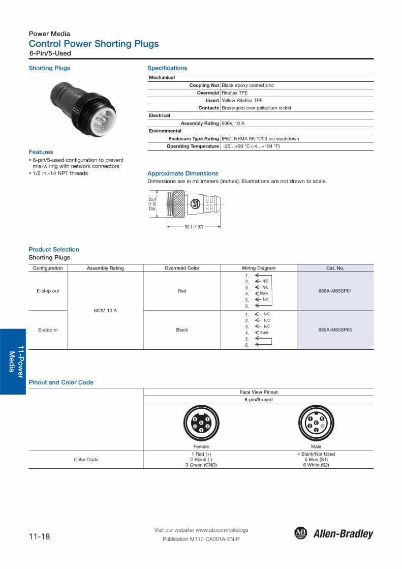
Shorting Plugs
Features� 6-pin/5-used configuration to prevent
mis-wiring with network connectors� 1/2 in.-14 NPT threads
Specifications
25.4(1.0)Dia.
50.1 (1.97)
Product SelectionShorting Plugs
Configuration Assembly Rating Overmold Color Wiring Diagram Cat. No.
E-stop out
600V, 10 A
Red
1.2.3.4.5.6.
N/C
N/C
N/C
Blank 889A-M65SP61
E-stop in Black
1.2.3.4.5.6.
N/C
N/C
N/C
Blank889A-M65SP65
Pinout and Color Code
Face View Pinout
6-pin/5-used
Female Male
Color Code 1 Red (+)2 Black (-)
3 Green (GND)
4 Blank/Not Used5 Blue (S1)6 White (S2)
Mechanical
Coupling Nut Black epoxy coated zinc
Overmold Riteflex TPE
Insert Yellow Riteflex TPE
Contacts Brass/gold over palladium nickel
Electrical
Assembly Rating 600V, 10 A
Environmental
Enclosure Type Rating IP67, NEMA 6P, 1200 psi washdown
Operating Temperature -20…+90 °C (-4…+194 °F)
Approximate DimensionsDimensions are in millimeters (inches). Illustrations are not drawn to scale.

Power Media
Three Phase and Control Power Accessories
11-19Visit our website: www.ab.com/catalogs
Publication M117-CA001A-EN-P
Locking Clips, Sealing Caps, Mounting Nuts, and Flat Seals
Gen
eral
Qui
ck S
elec
tion
Intr
od
uctio
nC
onn
ectio
nS
yste
ms
11-P
ow
erM
edia
Saf
ety
Co
nnec
tion
Net
wo
rk M
edia
Sealing Caps
Connector Style Material Thread Configuration Dimensions Cat. No.
Control Power (M22)
Aluminum grey, anodized
External, male
7/8 in. -16 UN 2 A Threads
Gasket
1485A-C1
Internal, female
7/8 in. -16 UN2 B Threads
Gasket889A-NCAP
3-Phase Power (M35)
External, male
1-3/8 in. -16 UN2A Threads
Gasket 889A-QMCAP
Internal, female
1-3/8 in. -16 UN2B Threads
Gasket 889A-QCAP
Accessories Specifications
Locking Clips Sealing Caps
Mechanical
Material ABS/PC plastics Anodized aluminum
Color Black Grey
Electrical
Non-current carrying, no ratings required
Environmental
Enclosure Type Rating No rating required IP67, NEMA 4 & 6P; 1200 psiwashdown
Product Selection
Locking Clips
Description Pkg. QuantityConnector
Style Cat. No.
Clam shell design clips over the three-phase power media drop connection, to limit customer access.10
M22 Connector 280-MTRLC-M22
Clam shell design clips over the three-phase power media trunk connection, to limit customer access. M35 Connector 280-MTRLC-M35

Power Supplies
Bulletin 1607 Power Supplies
11-20Visit our website: www.ab.com/catalogs
Publication M117-CA001A-EN-P
General
Quick S
election
Introd
uction
Co
nnection
System
s11-P
ow
erS
upp
liesS
afetyC
onnectio
nN
etwo
rk Med
ia
Features� IP67 and NEC Class 2 ratings� Vacuum encapsulation technology� Quick connectors� Smooth surface, suitable for washdown
Specifications
1607-XT50D1A 1607-XT100D1A 1607-XT200D1A 1607-XT200D2A
Output Power 48.0 W 91.2 W192 W (288 W
with bonuspower)
91.2 W peroutput
Input Voltage (47...63 Hz) 100…240V AC, 100...353V DC 100…240V AC, 100...300V DC
Operational Range 90…264V AC, 100...353V DC 90…264V AC, 100...300V DC
Power Factor Correction@ 47…63 Hz ⎯ >0.98 active
Hold-up Time 50 ms
Rated Input Current 1.0 A (115V AC), 0.5 A (230V AC)
2.0 A (115V AC), 1.0 A (230V AC)
2.4 A (115V AC), 1.2 A (230V AC)
2.2 A (115V AC), 1.1 A (230V AC)
Inrush Current <25 A
Efficiency >88%, 120V AC>89%, 230V AC
>82%, 120V AC>85%, 230V AC
Output Voltage 24V (+1%)
Rated Output Current 2.0 A 3.8 A 8 A 3.8 A per output
Reserve Power (typ. 4 s,60 s recovery time) ⎯ 12 A ⎯
Ripple Voltage <240 mVPP bandwidth, 1 MHz
Noise <480 mVPP bandwidth, 20 MHz
Overcurrent ProtectionElectronic current
limited to2.2…2.7 A
Electronic currentlimited to
3.8…4.1 A
Electronic currentlimited to
12.1…15.6 A(8.4…10.4 A after4 s bonus power
times out)
Electronic currentlimited to
3.8…4.1 A
AC Power On LEDIndication for Output 1 Yes
AC Power On LEDIndication for Output 2 ⎯ Yes
Operating TemperatureRange (Tamb)
-25...+70 °C (-13…158 °F)derate 2.5%/K,
50...70 °C (122…158 °F)
-25...+60 °C (-13…140 °F)derate 2%/K,
50...60 °C (122…140 °F)
Non-OperatingTemperature Range -40...+85 °C (-40…+185 °F)
Humidity up to 100% with condensation
MTBF♣ >500 000 hours
Dimensions (W x H x D) 140 x 36 x 85 mm(5.51 x 1.42 x 3.35 in.)
187 x 74 x 122 mm(7.36 x 2.91 x 4.80 in.)
Weight 750 g (1.65 lb) 3040 g (6.70 lb)
Ingress Protection IP67, EN 60529
Certifications/Standards
CE, UL 508 (UL Listed), UL 60950 (cURus)Safety standards = IEC/EN 60950, EN 60529
CE EN 60950; cULus Listed, UL508, cURus RecognizedUL60950/CSA C22.2, No. 60950-1
Special Features NEC Class 2 ⎯ NEC Class 2
♣ MTBF determined by Siemens norm SN 29500 at full load current and 40 °C (104 °F).

1607-XT50D1A and 1607-XT100D1A 1607-XT200D1A
1305
74
35
140
85(2.91)
(5.51)
(1.38)
(3.35)
(5.11)
Location ofKeying Tab
225(8.86)
6.6
100 (3.94)
122 (4.80)
74 (2.91)
22 (0.87)
187(7.36)
245(9.65)
Location ofKeying Tab
1607-XT200D2A
225(8.86)
6.6
100 (3.94)122 (4.80)
74 (2.91)
22 (0.87)
187(7.36)
245(9.65)
Location ofKeying Tab
Power Supplies
Bulletin 1607 Power Supplies
11-21Visit our website: www.ab.com/catalogs
Publication M117-CA001A-EN-P
Gen
eral
Qui
ck S
elec
tion
Intr
od
uctio
nC
onn
ectio
nS
yste
ms
11-P
ow
erS
upp
lies
Saf
ety
Co
nnec
tion
Net
wo
rk M
edia
Pinouts
Pin Connection
1 NC
2 L
3 N
Pin Connection
1 +
2 +
3 -
4 -
Input Output
Product Selection
Input Voltage Output Power [W] Output Voltage [V DC] Output Current [A] Inrush Current Cat. No.
Single Output
100…240V AC,100…353V DC
48.0
24 (+1%)
2.0
<25 A
1607-XT50D1A
91.2 3.8 1607-XT100D1A
192 (288 with bonus power) 8 1607-XT200D1A
Dual Output
100…240V AC,100…300V DC 91.2 per output 24 (+1%) 3.8 <25 A 1607-XT200D2A
Approximate DimensionsDimensions in millimeters (inches). Dimensions are not intended to be used for manufacturing purposes.
Note: When used with ArmorConnect control mediaan intermediate junction box, or field installableconnector, is required.
Power Supplies
Bulletin 1607 Power Supplies
11-22Visit our website: www.ab.com/catalogs
Publication M117-CA001A-EN-P
General
Quick S
election
Introd
uction
Co
nnection
System
s11-P
ow
erS
upp
liesS
afetyC
onnectio
nN
etwo
rk Med
ia
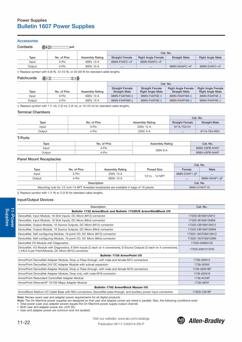
Input/Output Devices
Description Cat. No.
Bulletin 1732 ArmorBlock and Bulletin 1732D/E ArmorWeldBlock I/O
DeviceNet, Input Module, 16 Sink Inputs, DC Micro (M12) connector 1732D-IB16M12M12
DeviceNet, Input Module, 16 Sink Inputs, DC Micro (Mini) connector 1732D-IB16M12MINI
DeviceNet, Output Module, 16 Source Outputs, DC Micro (M12) connector 1732D-OB16M12M12
DeviceNet, Output Module, 16 Source Outputs, DC Micro (Mini) connector 1732D-OB16M12MINI
DeviceNet, Self-configuring Module, 16 point I/O, DC Micro (M12) connector 1732D-16CFGM12M12
DeviceNet, Self-configuring Module, 16 point I/O, DC Micro (Mini) connector 1732D-16CFGM12MN
DeviceNet I/O Module with Diagnostics 1732D-8X8M12D
DeviceNet, I/O Module with Diagnostics, 8 Sink Inputs (2 each on 4 connectors), 8 Source Outputs (2 each on 4 connectors),1.4/8.0 A per Point/Module, DC Micro (M12) connector 1732D-8X81212HD
Bulletin 1738 ArmorPoint I/O
ArmorPoint DeviceNet Adapter Module, Drop or Pass-through, with male and female M12 connectors 1738-ADN12
ArmorPoint DeviceNet 24V DC Adapter Module with subnet expansion 1738-ADNX
ArmorPoint DeviceNet Adapter Module, Drop or Pass-through, with male and female M18 connectors 1738-ADN18P
ArmorPoint DeviceNet Adapter Module, Drop only, with male M18 connector 1738-ADN18
ArmorPoint Redundant ControlNet Adapter Module 1738-ACNR
ArmorPoint Ethernet/IP 10/100 Mbps Adapter Module 1738-AENT
Bulletin 1792 ArmorBlock Maxum I/O
ArmorBlock MaXum I/O Cable Base with Mini connectors, DeviceNet pass-through, and auxiliary power input connection 1792D-CB18P
Note: Review exact user and adapter power requirements for all digital products. Note: The On-Machine power supplies are designed so that user and adapter power are wired in parallel. Also, the following conditions exist:� Total power (user plus adapter power) equals the On-Machine power supply output channel.� Both user and adapter power are +24V DC. � User and adapter power are common and not isolated.
Accessories
Cordsets
Type No. of Pins Assembly Rating
Cat. No.
Straight Female Right Angle Female Straight Male Right Angle Male
Input 3-Pin 600V, 13 A 889N-F3AFC-�F 889N-R3AFC-�F ⎯ ⎯Output 4-Pin 600V, 10 A ⎯ ⎯ 889N-M4AFC-�F 889N-E4AFC-�F
� Replace symbol with 6 (6 ft), 12 (12 ft), or 20 (20 ft) for standard cable lengths.
Patchcords
Type No. of Pins Assembly Rating
Cat. No.
Straight FemaleStraight Male
Straight FemaleRight Angle Male
Right Angle FemaleStraight Male
Right Angle FemaleRight Angle Male
Input 3-Pin 600V, 13 A 889N-F3AFNM-‡ 889N-F3AFNE-‡ 889N-R3AFNM-‡ 889N-R3AFNE-‡
Output 4-Pin 600V, 10 A 889N-F4AFNM-‡ 889N-F4AFNE-‡ 889N-R4AFNM-‡ 889N-R4AFNE-‡
‡ Replace symbol with 1 (1 m), 2 (2 m), 5 (5 m), or 10 (10 m) for standard cable lengths.
Terminal Chambers
Type No. of Pins Assembly Rating
Cat. No.
Straight Female Straight Male
Input 3-Pin 250V, 12 A 871A-TS3-N1 ⎯Output 4-Pin 250V, 9 A ⎯ 871A-TS4-NM1
T-Ports
Type No. of Pins Assembly Rating Cat. No.
Input 3-Pin300V 8 A
898N-33PB-N4KF
Output 4-Pin 898N-43PB-N4KF
Panel Mount Receptacles
Type No. of Pins Assembly Rating Thread Size
Cat. No.
Female Male
Input 3-Pin 250V, 13 A1/2 in. - 14 NPT
888N-D3AF1-§F ⎯Output 4-Pin 600V, 10 A ⎯ 888N-M4AF1-§F
Description Cat. No.
Mounting nuts for 1/2 inch-14 NPT threaded receptacles are available in bags of 10 pieces 889A-U1NUT-10
§ Replace symbol with 1 (1 ft) or 3 (3 ft) for standard cable lengths.