Embed Size (px)
Citation preview
Distribution Automation Handbook Section 8.13 Backup Protection
Distribution Automation Handbook (prototype)
Power System Protection, 8.13 Backup protection
1MRS757293
2
Contents 8.13 Backup Protection ......................................................................................................................... 3
8.13.1 Introduction .......................................................................................................................... 3 8.13.1.1 REQUIREMENTS FOR BACKUP PROTECTION ........................................................................................................................... 3 8.13.1.2 JUSTIFICATION OF RESERVE PROTECTION ............................................................................................................................. 3 8.13.1.3 TENTATIVE METHODOLOGY ................................................................................................................................................. 4
8.13.2 Fundamental Concepts ........................................................................................................ 4 8.13.2.1 POWER SYSTEM FAULTS ...................................................................................................................................................... 5 8.13.2.2 NON-POWER SYSTEM FAULT TRIPPINGS ............................................................................................................................... 5 8.13.2.3 POWER SYSTEM DISTURBANCES ........................................................................................................................................... 5
8.13.3 Backup Protection ................................................................................................................ 7 8.13.3.1 REMOTE BACKUP PROTECTION ............................................................................................................................................ 8 8.13.3.2 SUBSTATION LOCAL BACKUP PROTECTION......................................................................................................................... 10 8.13.3.3 CIRCUIT LOCAL BACKUP PROTECTION ............................................................................................................................... 11 8.13.3.4 DUPLICATED MAIN PROTECTIONS ...................................................................................................................................... 12 8.13.3.5 BREAKER FAILURE PROTECTION ........................................................................................................................................ 12 8.13.3.6 INTEGRATED PROTECTION TERMINALS ............................................................................................................................... 13 8.13.3.7 THE SINGLE-FAILURE CRITERION ....................................................................................................................................... 14
8.13.4 Performance Indices .......................................................................................................... 14 8.13.4.1 CORRECT PERFORMANCE OF PROTECTIONS ........................................................................................................................ 15 8.13.4.2 DEPENDABILITY OF PROTECTIONS ...................................................................................................................................... 15 8.13.4.3 SECURITY OF PROTECTIONS ................................................................................................................................................ 15 8.13.4.4 RELIABILITY OF PROTECTIONS ........................................................................................................................................... 18 8.13.4.5 DEPENDABILITY OF SWITCHING DEVICES ........................................................................................................................... 19 8.13.4.6 THE FAULT-CLEARING TIME............................................................................................................................................... 19
8.13.5 Reliability Performance ..................................................................................................... 21
Distribution Automation Handbook (prototype)
Power System Protection, 8.13 Backup protection
1MRS757293
3
8.13 Backup Protection
According to the International Electrotechnical Vocabulary [8.13.5], backup protection is intended to oper-ate when a power system fault is not cleared or an abnormal condition is not detected in the required time because of failure or inability of other protection to operate or failure of the appropriate circuit-breaker(s) to trip. The backup protection is, by definition, slower than the main protection. Utilities install backup pro-tection to improve the dependability of their fault-clearing system. Here, dependability is the probability of not failing to clear a power system fault or abnormality.
8.13.1 Introduction
Consider a power system protected by one main protection and one backup protection. The addition of a second main protection will increase the availability, dependability and performance of the fault-clearing system. In the USA and in other countries, the term backup protection designates a form of protection that operates independently of specified devices in the main protection system. There, the backup protection may duplicate the main protection or may be intended to operate only if the main protection system fails to operate or is temporarily out of service. Technical committees within the IEC have discussed the differenc-es between the main protection and backup protection for several years. Recently, IEC has reached an in-ternational agreement and published the definitions [8.13.5].
8.13.1.1 Requirements for Backup Protection
Backup protection shall operate when the main protection fails. A relay may fail to operate once or twice per 100 demands. In such a case, the protection system will not operate correctly and the circuit-breaker will not receive a tripping command. A circuit-breaker, in turn, may fail to open and break less than once per 1 000 demands. Such failures of a protection relay or a switching device may prevent the proper clear-ing of the fault.
The requirements for the backup protection are not independent of the requirements for the entire fault-clearing system. Some protection engineers [8.13.2] find it reasonable to apply the single-failure criterion when planning the fault-clearing system. Reference [8.13.4] contains the exact wording of the single-failure criterion. This wording comes from the reliability analysis of nuclear power plants. Protection engineers use an elementary form of the single-failure criterion that requires that the failure of any one component in a fault-clearing system must not result in failure to clear a power system fault or abnormality.
8.13.1.2 Justification of Reserve Protection
In the future, executives with little or no experience of power system protection will manage restructured power utilities. In such an environment, there will be a strong pressure to cut costs. Provocative questions arise, like: "Why should we invest in protection, it does not generate any kilowatt-hours?" "Why is one main protection not good enough, we have an insurance?" A question can be phrased: "Is reserve protection always necessary or can we trust one main protection with self-supervision?"
Few protection engineers can justify the cost associated with a YES. It is possible to operate a part of a power system without a reserve protection for some faults. Many power utilities consider that only one
Distribution Automation Handbook (prototype)
Power System Protection, 8.13 Backup protection
1MRS757293
4
main protection is good enough for phase-to-earth faults on small systems with an isolated neutral. The failure rate is low and the consequences may be unimportant if the system is situated within the fence of the substation. On the other hand, many protection engineers hesitate to take the responsibility of a NO. Few power utilities accept to operate effectively earthed power transmission systems with only one main protec-tion. The number of shunt faults per year is high, and the consequences of a failure to clear the fault may be serious.
8.13.1.3 Tentative Methodology
Some protection engineers may argue that it is the policy of the company to use two main protections and two backup protections. In the future, the management of the restructured power utilities will not accept such arguments. In such an environment, the protection engineers have to justify the costs for the protection system. It will not be sufficient to provide a technical justification. It will be necessary to provide an eco-nomical justification.
It may be concluded that the fault-clearing system shall, as a minimum, satisfy the external requirements. The cost of additional protection must be less than or of the same order of magnitude as the sum of:
1. The avoided cost for reinforcement of power lines and items of plant due to the reduction of fault-clearing time after the installation of second main protection or backup protection
2. The estimated reduction of the present value of future operation and maintenance cost due to im-provement of operational security after the installation of second main protection and backup protec-tion
3. The estimated reduction of the present value of future disturbance costs due to the reduction of the number of incorrectly cleared power system faults and abnormalities
The disturbance cost should include the cost associated with: (1) the risk for personal injury and property damage to third parties, (2) the risk for property damage to own power lines and items of plant, (3) the cus-tomer outage cost, (3) the voltage disturbances, (4) the customer complaints and (5) bad will.
8.13.2 Fundamental Concepts
Backup protection is an important function of the protection system. The protection engineer must coordi-nate the design of the backup protection with the design of the main protection. In this process, the protec-tion engineer cooperates with power system planners and designers. The protection engineer must be famil-iar with the requirements, the utility's system design criteria, the utility's plant specifications, the failure rates of the protected plant, the performance indices of the fault-clearing system, the reliability of protec-tion equipment and the probability that a switching device fails to interrupt the fault current. The power system planner should help formulate the requirements on the fault-clearing system. One consideration is the stability of the power system. Another consideration is the type of busbar. Protection engineers and power system designers must co-ordinate the demands on and performance of station equipment. It is ne-cessary to strike a balance between technical and economical benefits on one hand and risks associated with the escalation of the complexity of protection on the other hand.

Distribution Automation Handbook (prototype)
Power System Protection, 8.13 Backup protection
1MRS757293
5
8.13.2.1 Power System Faults
A power system fault is a power system abnormality that involves or is the result of a failure of primary equipment and normally requires the immediate disconnection of the faulty equipment from the rest of the power system by the tripping of the appropriate circuit-breakers. Power system faults can be shunt, series or combination faults.
8.13.2.2 Non-power System Fault Trippings
A non-power system fault tripping is an unwanted tripping of a circuit-breaker as a result of a fault other than power system fault. The unwanted operations of a protection in the absence of a power system fault or the tripping of a breaker due to other secondary equipment failure or to human error are examples of non-power system fault trippings. Also the term non-system fault is used as a synonym to non-power system fault tripping.
8.13.2.3 Power System Disturbances
Here, the term power system disturbance is used for a sequence of power system faults that the system op-erators treat as one incident. Figure 8.13.1 shows a system that will be used use to discuss this concept.
BD
C
400 kV
A130 kV
F
Figure 8.13.1: Single-line diagram for a system
It is assumed that a sustained phase-to-earth fault occurs at F on the power line from A to B. Also, there is one non-unit protection without telecommunication at A and another one at B. The protections initiate au-tomatic reclosing without synchronism check or voltage check. The final assumption is that the protection system, the breakers and the reclosing equipment operate correctly.
The protection at A detects the fault and trips the breaker at A. It interrupts the fault current after about 100 milliseconds. The protection at B detects the fault, but it lies outside Zone-1 of the protection. After about 400 milliseconds, the protection at B trips the breaker. It interrupts the fault current from B and the automatic reclosing equipment at A gives a closing command to the breaker after one second. It recloses onto the sustained fault, and the fault current starts to flow. The protection operates a second time and trips the breaker. It interrupts the fault current from A about 60 milliseconds later. After 1.5 second, the automat-
Distribution Automation Handbook (prototype)
Power System Protection, 8.13 Backup protection
1MRS757293
6
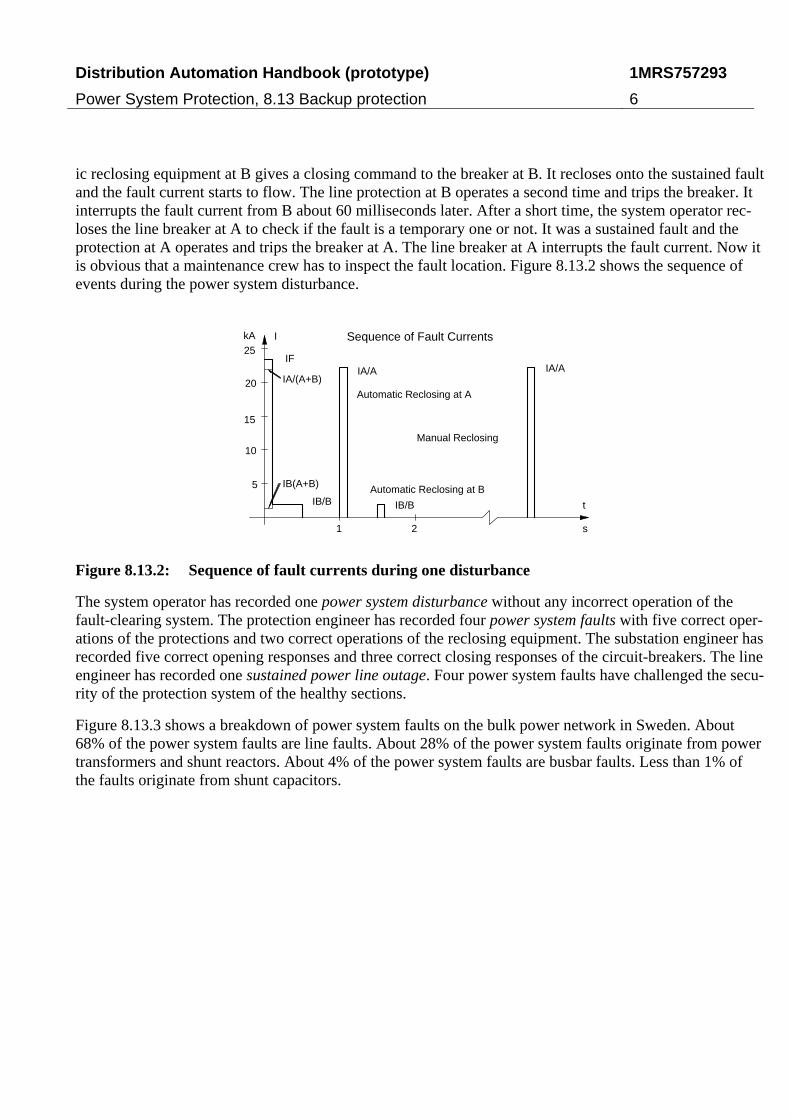
ic reclosing equipment at B gives a closing command to the breaker at B. It recloses onto the sustained fault and the fault current starts to flow. The line protection at B operates a second time and trips the breaker. It interrupts the fault current from B about 60 milliseconds later. After a short time, the system operator rec-loses the line breaker at A to check if the fault is a temporary one or not. It was a sustained fault and the protection at A operates and trips the breaker at A. The line breaker at A interrupts the fault current. Now it is obvious that a maintenance crew has to inspect the fault location. Figure 8.13.2 shows the sequence of events during the power system disturbance.
1 2 s
t
IkA
5
10
15
20
25Sequence of Fault Currents
IA/(A+B)
IB/B
IB(A+B)
IA/A
IB/B
IA/AIF
Automatic Reclosing at A
Automatic Reclosing at B
Manual Reclosing
Figure 8.13.2: Sequence of fault currents during one disturbance
The system operator has recorded one power system disturbance without any incorrect operation of the fault-clearing system. The protection engineer has recorded four power system faults with five correct oper-ations of the protections and two correct operations of the reclosing equipment. The substation engineer has recorded five correct opening responses and three correct closing responses of the circuit-breakers. The line engineer has recorded one sustained power line outage. Four power system faults have challenged the secu-rity of the protection system of the healthy sections.
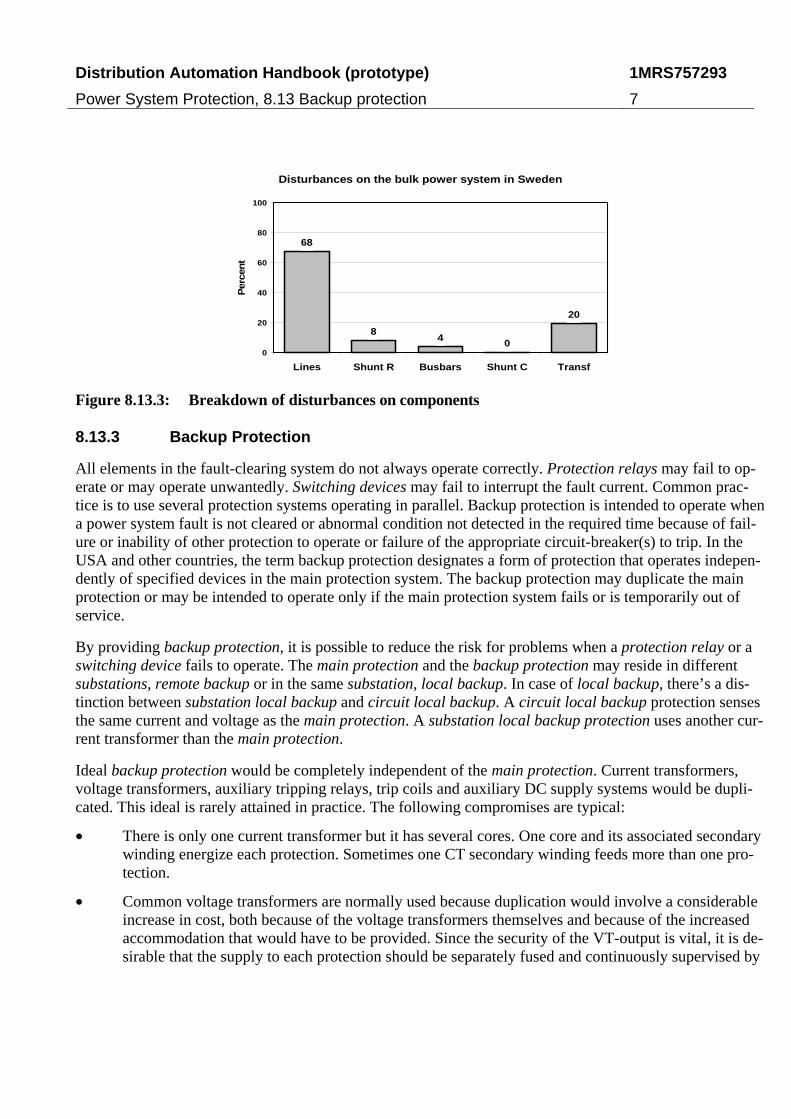
Figure 8.13.3 shows a breakdown of power system faults on the bulk power network in Sweden. About 68% of the power system faults are line faults. About 28% of the power system faults originate from power transformers and shunt reactors. About 4% of the power system faults are busbar faults. Less than 1% of the faults originate from shunt capacitors.
Distribution Automation Handbook (prototype)
Power System Protection, 8.13 Backup protection
1MRS757293
7
Disturbances on the bulk power system in Sweden
68
84
0
20
0
20
40
60
80
100
Lines Shunt R Busbars Shunt C Transf
Per
cen
t
Figure 8.13.3: Breakdown of disturbances on components
8.13.3 Backup Protection
All elements in the fault-clearing system do not always operate correctly. Protection relays may fail to op-erate or may operate unwantedly. Switching devices may fail to interrupt the fault current. Common prac-tice is to use several protection systems operating in parallel. Backup protection is intended to operate when a power system fault is not cleared or abnormal condition not detected in the required time because of fail-ure or inability of other protection to operate or failure of the appropriate circuit-breaker(s) to trip. In the USA and other countries, the term backup protection designates a form of protection that operates indepen-dently of specified devices in the main protection system. The backup protection may duplicate the main protection or may be intended to operate only if the main protection system fails or is temporarily out of service.
By providing backup protection, it is possible to reduce the risk for problems when a protection relay or a switching device fails to operate. The main protection and the backup protection may reside in different substations, remote backup or in the same substation, local backup. In case of local backup, there’s a dis-tinction between substation local backup and circuit local backup. A circuit local backup protection senses the same current and voltage as the main protection. A substation local backup protection uses another cur-rent transformer than the main protection.
Ideal backup protection would be completely independent of the main protection. Current transformers, voltage transformers, auxiliary tripping relays, trip coils and auxiliary DC supply systems would be dupli-cated. This ideal is rarely attained in practice. The following compromises are typical:
• There is only one current transformer but it has several cores. One core and its associated secondary winding energize each protection. Sometimes one CT secondary winding feeds more than one pro-tection.
• Common voltage transformers are normally used because duplication would involve a considerable increase in cost, both because of the voltage transformers themselves and because of the increased accommodation that would have to be provided. Since the security of the VT-output is vital, it is de-sirable that the supply to each protection should be separately fused and continuously supervised by
Distribution Automation Handbook (prototype)
Power System Protection, 8.13 Backup protection
1MRS757293
8
a relay that will give alarm on failure of the supply and, where appropriate, prevent an unwanted operation.
• Trip supplies to the two protections should be separately fused. Duplication of tripping batteries and trip coils on circuit-breakers is sometimes provided.
8.13.3.1 Remote Backup Protection
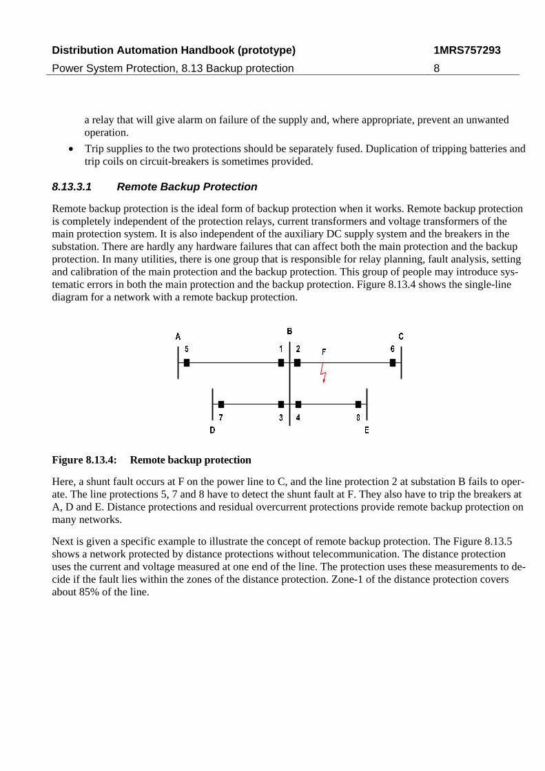
Remote backup protection is the ideal form of backup protection when it works. Remote backup protection is completely independent of the protection relays, current transformers and voltage transformers of the main protection system. It is also independent of the auxiliary DC supply system and the breakers in the substation. There are hardly any hardware failures that can affect both the main protection and the backup protection. In many utilities, there is one group that is responsible for relay planning, fault analysis, setting and calibration of the main protection and the backup protection. This group of people may introduce sys-tematic errors in both the main protection and the backup protection. Figure 8.13.4 shows the single-line diagram for a network with a remote backup protection.
Figure 8.13.4: Remote backup protection
Here, a shunt fault occurs at F on the power line to C, and the line protection 2 at substation B fails to oper-ate. The line protections 5, 7 and 8 have to detect the shunt fault at F. They also have to trip the breakers at A, D and E. Distance protections and residual overcurrent protections provide remote backup protection on many networks.
Next is given a specific example to illustrate the concept of remote backup protection. The Figure 8.13.5 shows a network protected by distance protections without telecommunication. The distance protection uses the current and voltage measured at one end of the line. The protection uses these measurements to de-cide if the fault lies within the zones of the distance protection. Zone-1 of the distance protection covers about 85% of the line.
Distribution Automation Handbook (prototype)
Power System Protection, 8.13 Backup protection
1MRS757293
9
Zone 1Zone 2
Zone 3
Step 1
Step 2
Step 3
AB
C
Time
Distance
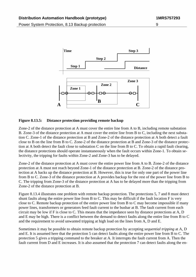
Figure 8.13.5: Distance protection providing remote backup
Zone-2 of the distance protection at A must cover the entire line from A to B, including remote substation B. Zone-3 of the distance protection at A must cover the entire line from B to C, including the next substa-tion C. Zone-1 of the distance protection at B and Zone-2 of the distance protection at A both detect a fault close to B on the line from B to C. Zone-2 of the distance protection at B and Zone-3 of the distance protec-tion at A both detect the fault close to substation C on the line from B to C. To obtain a rapid fault clearing, the distance protections should operate instantaneously when the fault occurs within Zone-1. To obtain se-lectivity, the tripping for faults within Zone-2 and Zone-3 has to be delayed.
Zone-2 of the distance protection at A must cover the entire power line from A to B. Zone-2 of the distance protection at A must not reach beyond Zone-1 of the distance protection at B. Zone-2 of the distance pro-tection at A backs up the distance protection at B. However, this is true for only one part of the power line from B to C. Zone-3 of the distance protection at A provides backup for the rest of the power line from B to C. The tripping from Zone-3 of the distance protection at A has to be delayed more than the tripping from Zone-2 of the distance protection at B.
Figure 8.13.4 illustrates one problem with remote backup protection. The protections 5, 7 and 8 must detect shunt faults along the entire power line from B to C. This may be difficult if the fault location F is very close to C. Remote backup protection of the entire power line from B to C may become impossible if many power lines, transformers or generators feed fault current to the busbar at B. The fault current from each circuit may be low if F is close to C. This means that the impedance seen by distance protections at A, D and E may be high. There is a conflict between the demand to detect faults along the entire line from B to C and the requirement to avoid unwanted tripping at high load on the lines from A, D and E.
Sometimes it may be possible to obtain remote backup protection by accepting sequential tripping at A, D and E. It is assumed here that the protection 5 can detect faults along the entire power line from B to C. The protection 5 gives a tripping command to the breaker at A. It interrupts the fault current from A. Then the fault current from D and E increases. It is also assumed that the protection 7 can detect faults along the en-
Distribution Automation Handbook (prototype)
Power System Protection, 8.13 Backup protection
1MRS757293
10
tire power line from B to C when the breaker at A is open. The protection 7 now gives a tripping command to the breaker at D. It interrupts the fault current from D. The protection at 8 can detect faults along the en-tire power line from B to C when the breakers 5 and 7 both are open. The protection at 8 now gives a trip-ping command to the breaker 8. It interrupts the fault current from E and the current in the fault. The total fault clearing time may be very long, several seconds. It is not always possible to accept such a long fault-clearing time. The heating, the elongation and the increased sag of the conductors of the power line from B to C may be unacceptable.
8.13.3.2 Substation Local Backup Protection
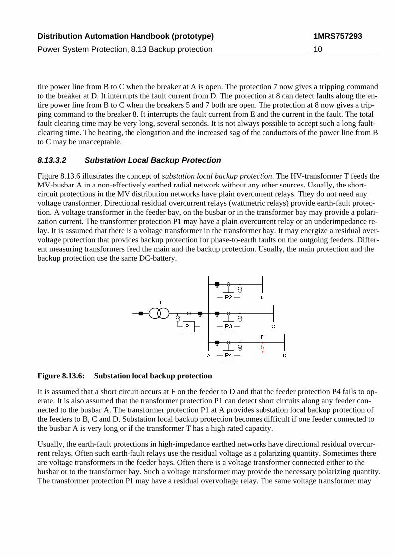
Figure 8.13.6 illustrates the concept of substation local backup protection. The HV-transformer T feeds the MV-busbar A in a non-effectively earthed radial network without any other sources. Usually, the short-circuit protections in the MV distribution networks have plain overcurrent relays. They do not need any voltage transformer. Directional residual overcurrent relays (wattmetric relays) provide earth-fault protec-tion. A voltage transformer in the feeder bay, on the busbar or in the transformer bay may provide a polari-zation current. The transformer protection P1 may have a plain overcurrent relay or an underimpedance re-lay. It is assumed that there is a voltage transformer in the transformer bay. It may energize a residual over-voltage protection that provides backup protection for phase-to-earth faults on the outgoing feeders. Differ-ent measuring transformers feed the main and the backup protection. Usually, the main protection and the backup protection use the same DC-battery.
Figure 8.13.6: Substation local backup protection
It is assumed that a short circuit occurs at F on the feeder to D and that the feeder protection P4 fails to op-erate. It is also assumed that the transformer protection P1 can detect short circuits along any feeder con-nected to the busbar A. The transformer protection P1 at A provides substation local backup protection of the feeders to B, C and D. Substation local backup protection becomes difficult if one feeder connected to the busbar A is very long or if the transformer T has a high rated capacity.
Usually, the earth-fault protections in high-impedance earthed networks have directional residual overcur-rent relays. Often such earth-fault relays use the residual voltage as a polarizing quantity. Sometimes there are voltage transformers in the feeder bays. Often there is a voltage transformer connected either to the busbar or to the transformer bay. Such a voltage transformer may provide the necessary polarizing quantity. The transformer protection P1 may have a residual overvoltage relay. The same voltage transformer may
Distribution Automation Handbook (prototype)
Power System Protection, 8.13 Backup protection
1MRS757293
11
feed both the main protection and the backup protection. The main protection and the backup protection are not completely independent of each other.
In case of an EHV transformer feeding an effectively earthed meshed HV network, the line protections P2, P3 and P4 may be distance protections. Usually, there are voltage transformers in the bays for the power lines to B, C and D. The transformer protection P1 may be an underimpedance protection. Usually there is a voltage transformer in the transformer bay. Sometimes there is only one voltage transformer connected to the busbar. The same voltage transformer may feed both the main protections and the backup protection. The main protection and the backup protection are not completely independent of each other.
It is difficult to obtain a backup protection of power lines in meshed networks by means of substation local backup protection only. In a meshed network, the distance protections P2, P3 and P4 may provide substa-tion local backup protection of the busbar. The distance protections P2, P3 and P4 may have an offset Zone-3 that covers the busbar. Another alternative is that the distance protections P2, P3 and P4 have an in-dependent and reverse-looking Zone-4 that covers the busbar. The reverse-looking Zone-4 may have a shorter operating time than an offset Zone-3 that must co-ordinate with Zone-2 of other distance protec-tions.
8.13.3.3 Circuit Local Backup Protection
Remote backup cannot always detect all faults on the adjacent power lines. One example is a meshed HV-network as shown in Figure 8.13.4. It is assumed that a shunt fault occurs at F on the power line between B and C and that the line protection 2 in substation B fails to operate. The line protections 5, 7 and 8 have to detect the shunt fault. The intermediate infeed at B will enlarge the impedances seen by the distance protec-tions at A, D and E. This enlargement may prevent the use of remote backup protection.
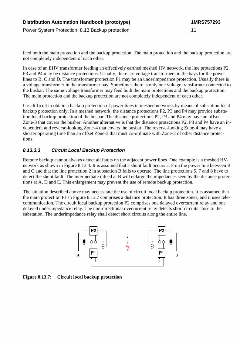
The situation described above may necessitate the use of circuit local backup protection. It is assumed that the main protection P1 in Figure 8.13.7 comprises a distance protection. It has three zones, and it uses tele-communication. The circuit local backup protection P2 comprises one delayed overcurrent relay and one delayed underimpedance relay. The non-directional overcurrent relay detects short circuits close to the substation. The underimpedance relay shall detect short circuits along the entire line.
Figure 8.13.7: Circuit local backup protection
Distribution Automation Handbook (prototype)
Power System Protection, 8.13 Backup protection
1MRS757293
12
8.13.3.4 Duplicated Main Protections
On EHV-networks, it is a common practice to use duplicated line protections, which provides mutual relay backup. One may use relays from different manufacturers, or relays based upon different principles. Proba-bly, the two relays will not suffer from the same design inadequacies. Theoretically, the use of different types of relays will increase the dependability. The use of two types of relays may, however, increase the risk for unwanted operation. Some utilities use two identical protections to maintain the security.
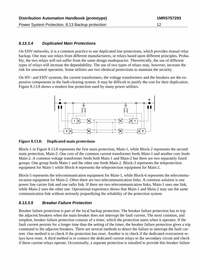
On HV- and EHV-systems, the current transformers, the voltage transformers and the breakers are the ex-pensive components in the fault-clearing system. It may be difficult to justify the cost for their duplication. Figure 8.13.8 shows a modern line protection used by many power utilities.
Figure 8.13.8: Duplicated main protections
Block-1 in Figure 8.13.8 represents the first main protection, Main-1, while Block-2 represents the second main protection, Main-2. One core of the common current transformer feeds Main-1 and another core feeds Main-2. A common voltage transformer feeds both Main-1 and Main-2 but there are two separately fused groups. One group feeds Main-1 and the other one feeds Main-2. Block-3 represents the teleprotection equipment for Main-1 while Block-4 represents the teleprotection equipment for Main-2.
Block-5 represents the telecommunication equipment for Main-1, while Block-6 represents the telecommu-nication equipment for Main-2. Often there are two telecommunication links. A common solution is one power line carrier link and one radio link. If there are two telecommunication links, Main-1 uses one link, while Main-2 uses the other one. Operational experience shows that Main-1 and Main-2 may use the same communication link without seriously jeopardizing the reliability of the protection system.
8.13.3.5 Breaker Failure Protection
Breaker failure protection is part of the local backup protection. The breaker failure protection has to trip the adjacent breakers when the main breaker does not interrupt the fault current. The most common, and simplest, breaker failure protection consists of a timer, which the protection starts when it operates. If the fault current persists for a longer time than the setting of the timer, the breaker failure protection gives a trip command to the adjacent breakers. There are several methods to detect the failure to interrupt the fault cur-rent. One method is to check if the protection has reset. Another is to check if the dedicated overcurrent re-lays have reset. A third method is to connect the dedicated current relays to the secondary circuit and check if these current relays operate. Occasionally, a separate protection is installed to provide this breaker failure
Distribution Automation Handbook (prototype)
Power System Protection, 8.13 Backup protection
1MRS757293
13
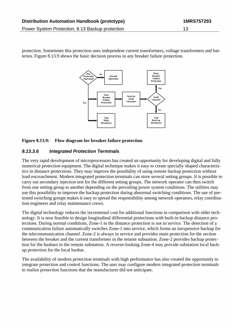
protection. Sometimes this protection uses independent current transformers, voltage transformers and bat-teries. Figure 8.13.9 shows the basic decision process in any breaker failure protection.
HasProtectionOperated?
FaultCleared?
Yes
No
Yes
No
NormalOperation
StartBreakerFailure
Protection
Wait forFault
Clearance
ResetBreakerFailure
Protection
TripBack-up
Breaker(s)
TripMain
Breaker(s)
Figure 8.13.9: Flow diagram for breaker failure protection
8.13.3.6 Integrated Protection Terminals
The very rapid development of microprocessors has created an opportunity for developing digital and fully numerical protection equipment. The digital technique makes it easy to create specially shaped characteris-tics in distance protections. They may improve the possibility of using remote backup protection without load encroachment. Modern integrated protection terminals can store several setting groups. It is possible to carry out secondary injection test for the different setting groups. The network operator can then switch from one setting group to another depending on the prevailing power system conditions. The utilities may use this possibility to improve the backup protection during abnormal switching conditions. The use of pre-tested switching groups makes it easy to spread the responsibility among network operators, relay coordina-tion engineers and relay maintenance crews.
The digital technology reduces the incremental cost for additional functions in comparison with older tech-nology. It is now feasible to design longitudinal differential protections with built-in backup distance pro-tections. During normal conditions, Zone-1 in the distance protection is not in service. The detection of a communication failure automatically switches Zone-1 into service, which forms an inexpensive backup for the telecommunication channel. Zone-2 is always in service and provides main protection for the section between the breaker and the current transformer in the remote substation. Zone-2 provides backup protec-tion for the busbars in the remote substation. A reverse-looking Zone-4 may provide substation local back-up protection for the local busbar.
The availability of modern protection terminals with high performance has also created the opportunity to integrate protection and control functions. The user may configure modern integrated protection terminals to realize protection functions that the manufacturer did not anticipate.

Distribution Automation Handbook (prototype)
Power System Protection, 8.13 Backup protection
1MRS757293
14
8.13.3.7 The Single-Failure Criterion
Some utilities find it reasonable to apply the single-failure criterion in the planning of the fault-clearing system. Protection engineers use an elementary form of the single-failure criterion that requires that the failure of any one component in a fault-clearing system should not result in a complete failure to clear a power system fault or abnormality. The single-failure criterion can be applied as follows:
1. The power system is considered: (a) in its normal switching state or (b) in a switching state where one power line is out of service.
2. A power system fault occurs on the power system. (a) three-phase short circuits, (b) phase-to-earth faults and (c) single-phase series faults are considered.
3. There is one fault in the fault-clearing system, and the following are considered: (a) a loss of input from a voltage transformer, (b) a loss of input from a current transformer, (c) a failure to operate of a protection relay, (d) a blown DC fuse, (e) an interruption of a tripping circuit and (f) a failure to oper-ate of a switching device.
4. To be checked if the faulty fault-clearing system will clear the power system fault at predefined loca-tions. The following must be considered: (a) an arbitrary line fault, (b) a busbar fault and (c) a fault on each of the terminals of power transformers. A second main protection or backup protection must be added until the fault-clearing system clears all faults.
5. To be checked if the healthy lines and healthy items of the plant can withstand the fault current for the above cases. A second main protection or backup protection to be added or the primary equipment reinforced until it withstands the fault current during the fault-clearing time.
The protection engineer must carry out a more detailed analysis to make clear the above procedure. Ques-tions to be answered include: Is it sufficient to consider the outage of one power line? Is it necessary to consider the outage of a power transformer without changing the settings of the relays? Is it sufficient to consider only one state of the generating system? Is it necessary to consider faults between current trans-formers and circuit-breakers? Is it necessary to consider phase-to-earth faults on non-effectively earthed systems within substations? Is it necessary to consider other failures in the fault-clearing system? How to assess outage costs?
8.13.4 Performance Indices
To be able to assess quantitatively the reliability of fault-clearing systems, a set of performance indices has to be defined. It is also useful to compile data on the reliability performance of the fault-clearing system. Some performance indices for protection systems and switching devices are introduced. Also some reliabil-ity performance data are reproduced. The fault-clearing system is divided into subsystems. They include the first main protection (Main-1), the backup protections, the switching devices and the second main protec-tion (Main-2). The subsystems for a power line or an item of plant are considered. It is also possible to de-fine reliability performance indices for protective relays, but it is outside the scope here.
Distribution Automation Handbook (prototype)
Power System Protection, 8.13 Backup protection
1MRS757293
15
8.13.4.1 Correct Performance of Protections
The tasks of the fault-clearing system are to: (1) detect power system faults and abnormalities, (2) identify the faulty item of plant and (3) interrupt the fault currents as quickly as reasonable. Performance indices measure: (1) the probability of not having a failure to operate, (2) the ability of not having an unwanted op-eration and (3) the probability of interrupting the fault current.
Three situations are considered: In the first case, there is a power system fault for which the protection shall operate. The protection operates correctly if it issues a tripping command. It operates incorrectly if it does not issue a tripping command. In the second case, there is a power system fault for which the protection shall not operate. In the third case, there is neither a power system fault nor an abnormality, and the protec-tion shall not operate. The protection system operates incorrectly if it issues a tripping command in the second and third case. It operates correctly if it refrains from issuing a tripping command in the second and third case. In most cases, the switching devices shall open and interrupt the fault current when it receives a command. A switching device operates correctly if it opens and interrupts the fault current when it receives an opening command. An exception is the bypass device for series capacitors. It operates correctly if it closes and carries the (fault) current when it receives a closing command.
8.13.4.2 Dependability of Protections
The dependability of protection is the probability for a protection of not having a failure to operate under given conditions for a given time interval. An index of dependability should measure the ability of the pro-tection system to operate when there is a power system fault for which the protection shall operate. It is easy to add the number of internal faults and the number of correct operation of the protection system for those faults. This means that the relative frequency of correct operations can be calculated. It also means that the probability of correct operation can be discussed. The index D of dependability is defined as fol-lows:
fc
c
fc
fs
s
f
NN
N
NN
NN
N
ND
+=
+−
=−= 1 (8.13.1)
Here, fN is the number of failures to operate at internal power system faults, sN is the number of internal
power system faults and cN is the number of correct operations, at internal power system faults, during the
given time interval. The performance index D as defined by equation (8.13.1) above measures the perfor-mance of the protection only when there is a power system fault. Incorrect operations at power system faults for which the protection should not have operated do not influence the index of dependability. The performance index D as defined by equation (8.13.1) above satisfies the axioms for a probability measure.
8.13.4.3 Security of Protections
The security of protection is the probability for a protection of not having an unwanted operation for a giv-en time interval. An index of security should measure the ability of the protection not to operate when it should not. Some power utilities define a measure S of security as follows.
Distribution Automation Handbook (prototype)
Power System Protection, 8.13 Backup protection
1MRS757293
16
uc
c
NN
NS
+= (8.13.2)
Here cN is the number of correct operations and uN is the number of unwanted operations of the protection
during the given time interval. Failures to operate do not affect the performance index S as defined by equ-ation (8.13.2) above. This performance index is easy to calculate and use. It is easy to count the number of unwanted operations and the number of correct operations for a given protection and a given time interval. It is most relevant for temporal comparison of the security of a given protection system.
The performance index S defined by equation (8.13.2) above is, unfortunately, not the relative frequency corresponding to the probability of not having an unwanted operation. The reason is that the denominator
uc NN + does not count the number of events when the protection system could have operated unwantedly
but did not. This means that the performance index S as defined by equation (8.13.2) does not measure the probability for a protection of not having an unwanted operation for a given time interval. The performance index does, however, measure the ability for a protection of not having an unwanted operation for a given time interval.
The performance index S defined by equation (8.13.2) above measures the performance of the protection both when there is a power system fault and when there is no power system fault. It is easy to determine if there was a power system fault or not when adding up the number of unwanted operations. This means that the number of unwanted operations uN can be separated as follows:
uuusu NNN += (8.13.3)
Here usN is the number of spontaneous unwanted operations of the protection and uuN is the number of
unselective operations of the protection during a given time interval. A spontaneous unwanted operation of a protection is an operation of the protection without any power system fault or abnormality. An unselec-tive operation of a protection is an unwanted operation of a protection when there is a power system fault or abnormality for which the protection should not have operated. The term spontaneous unwanted operation is used as a synonym to non-power system fault tripping. It is an incident which results in the unwanted tripping of a circuit-breaker as a result of a fault, other than power system fault, such as the unwanted oper-ation of protection in the absence of a power system fault or the tripping of a circuit-breaker due to some other secondary equipment or to human error.
The number of spontaneous unwanted operations of a protection usN does not depend directly on the num-
ber of power system faults. It is, however, possible to define a rate of spontaneous unwanted operations
uλ .
p
usu T
N=λ (8.13.4)
Distribution Automation Handbook (prototype)
Power System Protection, 8.13 Backup protection
1MRS757293
17
Here pT is the given time interval. It is easy to count the number of spontaneous unwanted operations and
estimate the rate of spontaneous operations. It depends on the properties of the protection proper and on the environment in the substation. The spontaneous unwanted operations include unwanted trippings of circuit-breakers from the protection as result of human errors. This means that the complexity of the protection system, testing, fault tracing and maintenance activities in the substation may influence the rate of sponta-neous unwanted operations.
An unselective operation of a protection is an unwanted operation of a protection when there is a power system fault or abnormality for which the protection should not have operated. The number of such unse-lective operations of the protection uuN depends on the number of external power system faults. The num-
ber also depends on the probability for the protection of operating unwantedly in case of an external power system fault. The risk of encountering an unselective operation is high if the power system fault occurs near the protected section. The risk of encountering an unselective operation is low if the power system fault oc-curs far from the protected section.
The probability of encountering an unselective operation can be approximated by the measure U given by the expression below:
en
uu
N
NU = (8.13.5)
Here enN is the number of external power system faults that occur near but still outside the protected sec-
tion. The crux is to define a zone of a power system that is near but still outsidethe protected section. In theory, such a zone could be defined as the union of all fault locations external to the protected section where a power system fault causes some response in the protection. A measure of the probability of en-countering an unselective operation could be defined as the number unselective operations of the protection divided by the total number of responses to external power system faults and abnormalities. Such a measure would then depend on the probability of not having a failure to respond to an external fault. In practice, such a definition is too complex for practical data collection.
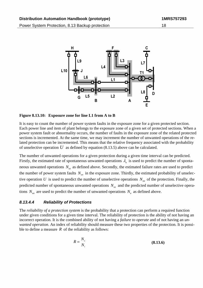
The IEEE working group D5 on performance measures for the microprocessor-based transmission line re-lays has introduced the concept of an exposure zone, [8.13.6] and [8.13.7]. The concept represents a signifi-cant innovation and may pave the way for better performance indices. Here is demonstrated the concept of an exposure zone in a couple of examples. First is considered the power line L1 in Figure 8.13.10. The power line L1 runs from busbar A to busbar B in Figure 8.13.10. The power lines L2, L3, ..., Lk terminate at busbar A or at busbar B in Figure 8.13.10. The transformers T1, T2, ..., Tm terminate at busbar A or at busbar B in Figure 8.13.10. Busbar A and B may energize shunts (such as shunt capacitors and shunt reac-tors) S1, S2, ..., Sn not shown in Figure 8.13.10.The exposure zone of the protected power line L1 is de-fined as the union of: (1) the power lines, L2, L3, ..., Lk, (2) the power transformers, T1, T2, ... , Lm, and (3) the shunts S1, S2, ..., Sn. Also the exposure zone of other protected sections, such as power transfor-mers, busbars and generating units, can be defined in a similar way.
Distribution Automation Handbook (prototype)
Power System Protection, 8.13 Backup protection
1MRS757293
18
Figure 8.13.10: Exposure zone for line L1 from A to B
It is easy to count the number of power system faults in the exposure zone for a given protected section. Each power line and item of plant belongs to the exposure zone of a given set of protected sections. When a power system fault or abnormality occurs, the number of faults in the exposure zone of the related protected sections is incremented. At the same time, we may increment the number of unwanted operations of the re-lated protection can be incremented. This means that the relative frequency associated with the probability of unselective operation U as defined by equation (8.13.5) above can be calculated.
The number of unwanted operations for a given protection during a given time interval can be predicted. Firstly, the estimated rate of spontaneous unwanted operations uλ is used to predict the number of sponta-
neous unwanted operations usN as defined above. Secondly, the estimated failure rates are used to predict
the number of power system faults enN in the exposure zone. Thirdly, the estimated probability of unselec-
tive operation U is used to predict the number of unselective operations uuN of the protection. Finally, the
predicted number of spontaneous unwanted operations usN and the predicted number of unselective opera-
tions uuN are used to predict the number of unwanted operations uN as defined above.
8.13.4.4 Reliability of Protections
The reliability of a protection system is the probability that a protection can perform a required function under given conditions for a given time interval. The reliability of protection is the ability of not having an incorrect operation. It is the combined ability of not having a failure to operate and of not having an un-wanted operation. An index of reliability should measure these two properties of the protection. It is possi-ble to define a measure R of the reliability as follows:
i
c
N
NR = (8.13.6)
Distribution Automation Handbook (prototype)
Power System Protection, 8.13 Backup protection
1MRS757293
19
Here cN is the number of correct operations and iN is the number of incorrect operations during the given
time interval. Equation (8.13.7) below defines the number of incorrect operations iN during the given time
interval:
ufi NNN += (8.13.7)
Here fN is the number of failures to operate on internal power system faults and uN is the number of un-
wanted operations of the protection during the given time interval. The performance index R as defined by equation (8.13.7) is easy to calculate and use. It is easy to count the number of failures to operate at internal power system faults, the number of unwanted operations and the number of correct operations for a given protection and a given time interval. The performance index R is most relevant for a temporal comparison of the reliability of a given protection system.
8.13.4.5 Dependability of Switching Devices
The dependability of a switching device is the probability of not having a failure to interrupt the fault cur-rent when the device has received a trip command. The dependability of a bypass device is the probability of not having a failure to make the (fault) current when the device has received a closing command. Equa-tion (8.13.8) defines a measure D of the dependability of a switching device:
fc
c
NN
ND
+= (8.13.8)
Here cN is the number of number of correct responses when the device has received an operating command
and fN is the number of failures to respond.
8.13.4.6 The Fault-clearing Time
As mentioned before, the tasks of the fault-clearing system are to: (1) detect power system faults, (2) identi-fy the faulty item of plant and (3) interrupt the fault currents as quickly as reasonable. The performance in-dices above measure (1) the probability of not having a failure to operate, (2) the ability of not having an unwanted operation and (3) the probability of breaking or making the (fault) current.
However, the performance indices do not explicitly measure the speed of operation. Many utilities want to measure this speed and some authorities require it. Equation (8.13.9) defines the fault-clearing time fT :
{ }ifNi
f TMaxT ,1=
= (8.13.9)
Here ifT , is the fault-clearing time at terminal i of the protected section, and N is the number of terminals
(usually two) of the protected section.
Equation (8.13.10) below defines the fault-clearing time ifT , at terminal i of the protected section:
Distribution Automation Handbook (prototype)
Power System Protection, 8.13 Backup protection
1MRS757293
20
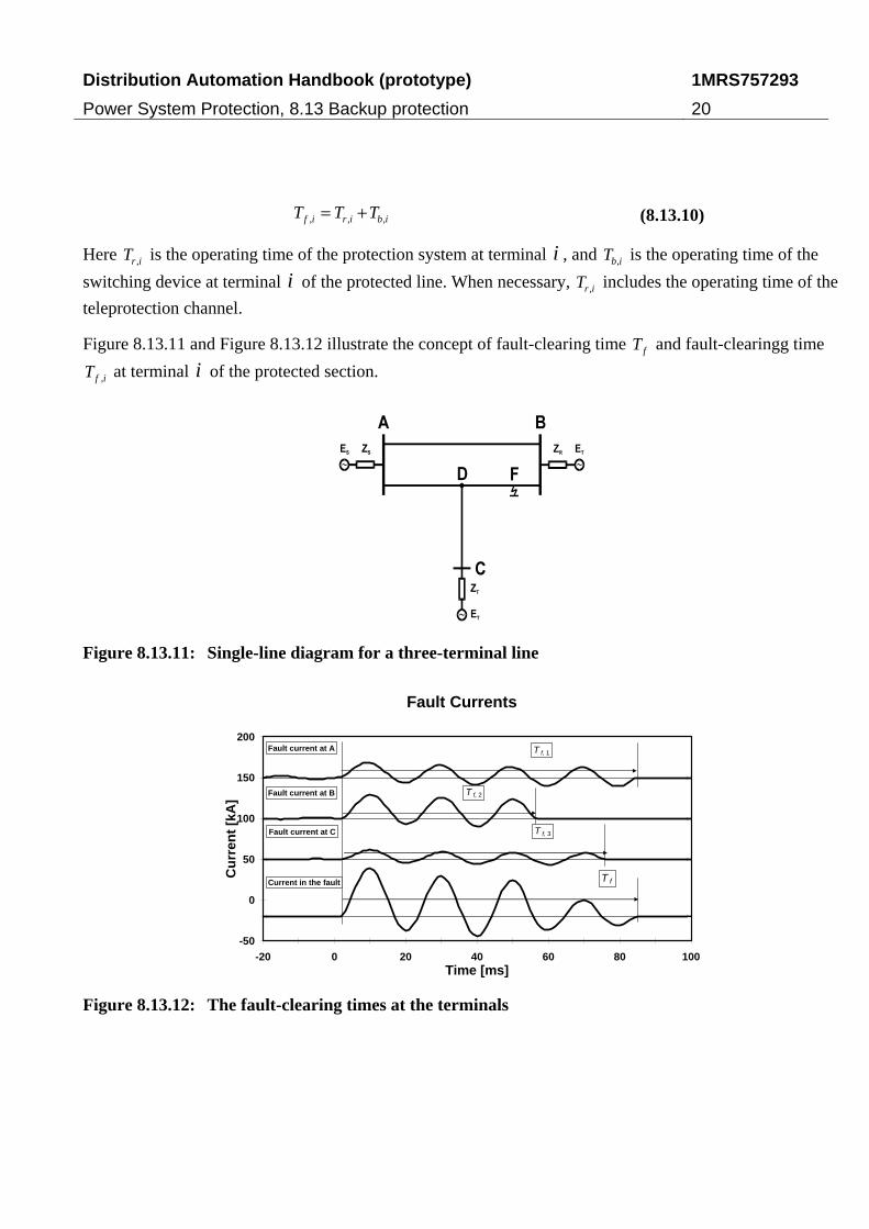
ibirif TTT ,,, += (8.13.10)
Here irT , is the operating time of the protection system at terminal i , and ibT , is the operating time of the
switching device at terminal i of the protected line. When necessary, irT , includes the operating time of the
teleprotection channel.
Figure 8.13.11 and Figure 8.13.12 illustrate the concept of fault-clearing time fT and fault-clearingg time
ifT , at terminal i of the protected section.
Figure 8.13.11: Single-line diagram for a three-terminal line
Fault Currents
-50
0
50
100
150
200
-20 0 20 40 60 80 100Time [ms]
Cu
rren
t [k
A]
T f
T f, 1
T f, 2
T f, 3
Fault current at A
Fault current at B
Fault current at C
Current in the fault
Figure 8.13.12: The fault-clearing times at the terminals
Distribution Automation Handbook (prototype)
Power System Protection, 8.13 Backup protection
1MRS757293
21
8.13.5 Reliability Performance
Below is reproduced and discussed some reliability performance data for fault-clearing systems. It is neces-sary to be very cautious when collecting, comparing and using such statistical data.
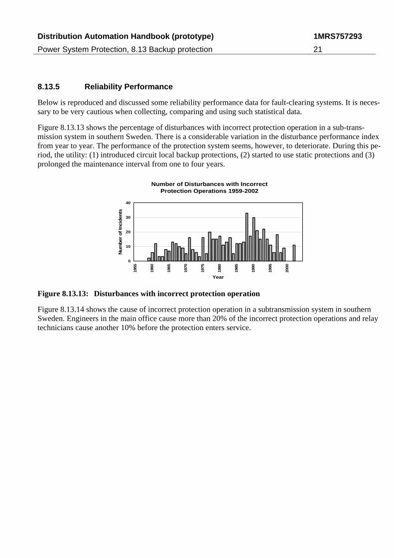
Figure 8.13.13 shows the percentage of disturbances with incorrect protection operation in a sub-trans-mission system in southern Sweden. There is a considerable variation in the disturbance performance index from year to year. The performance of the protection system seems, however, to deteriorate. During this pe-riod, the utility: (1) introduced circuit local backup protections, (2) started to use static protections and (3) prolonged the maintenance interval from one to four years.
Number of Disturbances with IncorrectProtection Operations 1959-2002
0
10
20
30
40
1955
1960
1965
1970
1975
1980
1985
1990
1995
2000
Year
Num
ber
of In
cid
ents
Figure 8.13.13: Disturbances with incorrect protection operation
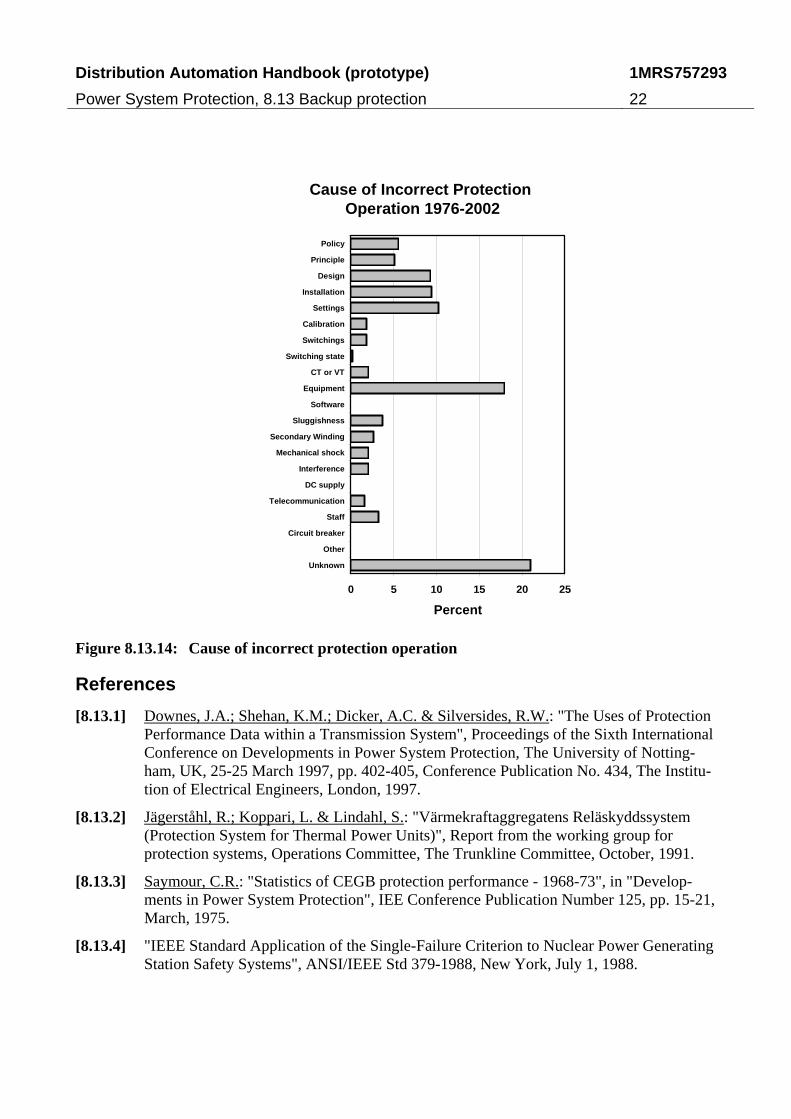
Figure 8.13.14 shows the cause of incorrect protection operation in a subtransmission system in southern Sweden. Engineers in the main office cause more than 20% of the incorrect protection operations and relay technicians cause another 10% before the protection enters service.
Distribution Automation Handbook (prototype)
Power System Protection, 8.13 Backup protection
1MRS757293
22
Cause of Incorrect Protection Operation 1976-2002
0 5 10 15 20 25
Policy
Principle
Design
Installation
Settings
Calibration
Switchings
Switching state
CT or VT
Equipment
Software
Sluggishness
Secondary Winding
Mechanical shock
Interference
DC supply
Telecommunication
Staff
Circuit breaker
Other
Unknown
Percent
Figure 8.13.14: Cause of incorrect protection operation
References
[8.13.1] Downes, J.A.; Shehan, K.M.; Dicker, A.C. & Silversides, R.W.: "The Uses of Protection Performance Data within a Transmission System", Proceedings of the Sixth International Conference on Developments in Power System Protection, The University of Notting-ham, UK, 25-25 March 1997, pp. 402-405, Conference Publication No. 434, The Institu-tion of Electrical Engineers, London, 1997.
[8.13.2] Jägerståhl, R.; Koppari, L. & Lindahl, S.: "Värmekraftaggregatens Reläskyddssystem (Protection System for Thermal Power Units)", Report from the working group for protection systems, Operations Committee, The Trunkline Committee, October, 1991.
[8.13.3] Saymour, C.R.: "Statistics of CEGB protection performance - 1968-73", in "Develop-ments in Power System Protection", IEE Conference Publication Number 125, pp. 15-21, March, 1975.
[8.13.4] "IEEE Standard Application of the Single-Failure Criterion to Nuclear Power Generating Station Safety Systems", ANSI/IEEE Std 379-1988, New York, July 1, 1988.
Distribution Automation Handbook (prototype)
Power System Protection, 8.13 Backup protection
1MRS757293
23
[8.13.5] "International Electrotechnical Vocabulary, Chapter 448: Power System protection", Publication 50(448), Second edition 1995-12, International Electrotechnical Commis-sion, Geneva, 1995.
[8.13.6] "Proposed Statistical Performance Measures for Microprocessor-based Transmission-line Protective Relays: Part I -- Explanation of the Statistics", IEEE Transactions on Power Delivery, vol. 12, no. 1, pp. 134-143, January, 1997.
[8.13.7] "Proposed Statistical Performance Measures for Microprocessor-based Transmission-line Protective Relays: Part II -- Collection and Uses of Data", IEEE Transactions on Power Delivery, vol. 12, no. 1, pp. 144-156, January, 1997.
Document revision history
Document revision/date History
A / 07 October 2010 First revision Disclaimer and Copyrights
The information in this document is subject to change without notice and should not be construed as a commitment by ABB Oy. ABB Oy assumes no responsibility for any errors that may appear in this document.
In no event shall ABB Oy be liable for direct, indirect, special, incidental or consequential damages of any nature or kind aris-ing from the use of this document, nor shall ABB Oy be liable for incidental or consequential damages arising from use of any software or hardware described in this document.
This document and parts thereof must not be reproduced or copied without written permission from ABB Oy, and the contents thereof must not be imparted to a third party nor used for any unauthorized purpose.
The software or hardware described in this document is furnished under a license and may be used, copied, or disclosed only in accordance with the terms of such license.
Copyright © 2010 ABB Oy
All rights reserved.
Trademarks
ABB is a registered trademark of ABB Group. All other brand or product names mentioned in this document may be trade-marks or registered trademarks of their respective holders.

This page is intentionally left blank.

This page is intentionally left blank.

This page is intentionally left blank

© C
opyr
ight
201
1 A
BB
. All
right
s re
serv
ed. 1
MR
S75
7293
A
Contact information
ABB Oy, Distribution Automation P.O.Box 699 Visiting address: Muottitie 2A FI-65101 Vaasa, FINLAND Phone: +358 10 22 11 Fax: +358 10 22 41094 www.abb.com/substationautomation