Embed Size (px)
Citation preview
lJ1
j1
,.' .-- -",,~t'''''''I1.c ,eVii<;;;r~?,~·,t"~~~;·.x
{: ,\1,
80!:
____ ._ .... J~_'__t5· 0 26
.,..
[';PIOY-ID FOR PUBliC RElEASE; DISTR~BunON UNLlM~
OTIC
S-·',"--'-' ~"..CTED". ~ :s:;;.
i:,t,"~; ~;;~ 1 6 1900·
ROME AIR DEVELOPMENT CINTER AAir Force Systems CommandGrlHlss Air Force B<l58, New Yor:t 13441
Spencer J. RochefortRa imundas Sukys~orman C. Poirier
A RADIATING CABLE n~JTRUSION
DETECTION SYSTEMNortheastern Univenity
IADC·...O·l :"5. lllnal'echnlcal leport
June 1910
• iI
! I
I •
> _. --- ... . ~--
\''_OM ••
If your address has changed or if you wish to be removed from t_ 1tADC" ,i,
maiUflg list, or :1f the addres~~ is no Long rr eJD!:loyed by your or,.m.,~~'t"tton, please notify.RADC (EEC) , ~nscom AFB MA 01731. This will ~~el.t ~,
us in maintaining a curr~nt maillng\list.\
Do not return this copy. Retai~ or ~e8t~OY.
s-, .'
/',.....,.1' ....:::J~ , "FOR THE COMMANDERl c7·~-I'· / ...........
~;,~.
NICHOLAS V. lCARASProject Engineer
ALLAN C. SCHELLChief, Electromagnetic Sciences Diviei':.ll
JOHN P. HUSSActing Chief,- Plana Offi~.,
'ril,"\(
, \\'~'\ • \.'j
-
APPROVED:
APPROVlID:
'thla report 'hu beell ren_" v tb.a -l.DC 'ublic: Aff.ire Of:1-' (p.:Illn4 ~.• ,rd....bh to tbw RaUonal 'l_dua1cal Ll'lfotliation, Service (lftt.).AtMTlS it will H eel...tlhle to the aoneral public. 1nclud1na for_lI_WltlOQ8.
Unc..n ...SG-115 ha. be.pu reviewed and 18 approved fol' pubUc4tioa.
.•!rt '.~'-.. ''''-''
, I
j
i1
. i;,
I ..fI "i
I ' ,
J
l
i
II
UNCLASSIFIED ,SE':U~ITY CLASSIFICATION OF THIS PAOE (""." DO,' ~\
.:L.:l. '7500 J!1473
UNCLASSIFIED
FOIIMI ~AN 7JDO
IEC~VC~ SSIFIC:ATION OF THIS ".OE (11'/I." D.,o E,,'.,od)
@I l'i} REPORT DOCUMENTArlON PAGE READ INSTRUCTIONS
BEFORE COMPLETING FO~M
~~rrR-8(1-17~ - ~~;jq()£S91'~~IEJ'S C.TAL.OO NUM.t:A
. ..
(~1- - v O~Ta PEtD~~~
~ ~IATING~BLE.£NTRUSION~E~ON ~STEM"J JFina~technical ep_t.l8Se 78-3Dc791.. ", .._.' ---~.-
AMINO 0 .. 0. ~EP "
Ib)N/A
~(o)
Spencer J.!Rochefort / @ F19628-78-C~~~~Raimundas.l Sukys
'"-' - PM'Norman C. j Poirier~. . ! o AOOIIESS .......... 't~'''C'.,,~A~EA • WO~K UN ...t:RSNortheastern Univ~y
627n2F j,-1Electronics Rese~rch L8b9FS~gry rt: 46/J1'53l J '7 ..1 SBoston MA 02115 e-:
'I. C:ONTIIOL.L.INO OFFICI! NAME .NO AOD~ESS -Deputy for Electronic Technology (RAD~ JU~8rjl r'
Hanscom AFB MA 01731 AOES,... 52
'~a::""'" ....cv ".'C7d-J'5 .i..
IS. SECU"ITV CI.•ASS. (0' ,"'. 'OPO,')"'co)
UNCLASSIFIED
110. OECL.ASSIFICATION DOWNO~ADINO
NI iCHEDUL.E
16. DISTRllIUTlOt, STATEMENT (01/1". Ropo,')
Approved for public release; distribution unlimited.
17. DISTRIBUTION ST., EMENT (01'''. o"o"oc' .",...d I:> Dlocle 20.1/ dIU.,.", ,,_ Ropo,')
Same
'I. SUPPL. ZMEN T AIIV NOTES
RADC Project Engineer: NICHOLAS V, KARAS (RADC/EEC)
,t. KEV WORDS (COII""u. 0" ,.V.,.' old. 1/ nee.....,. .,d Ido,,"')' b)' b/ocl< r.umbo,)
Intruder DetectionRacilating CableSignal CancellationQuadrature Detection
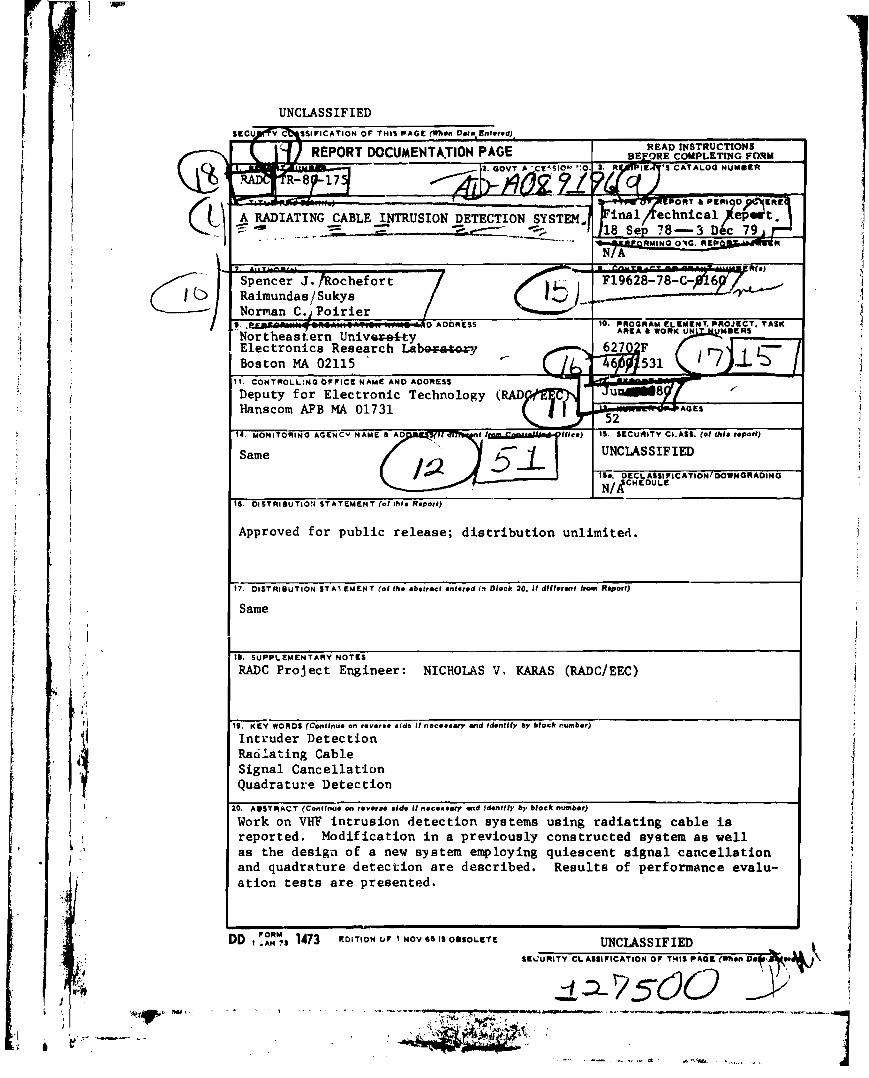
20.•IISTII"CT (Co"l/"u. 011 'OV'''O old. 1/ ".c....". ..d Id."",)' "" "/ocle "UIII".')
Work on VHF intrusion detection systems using radiating cable iareported. Modification in a previously constructed system as wellas the design of a new system employing quiescent aignal cancellationand quadr~ture detection are described. Results of performance evalu-ation tests are presented.
~•. _.. ,
't:",",'--~-•
r,If
t'!(.
I i
I.:
t il ! .1,.t~ .'j l:f "
/I
11
I
!.'
i11jj
,.'
j
j1
III1
-
8
5
1
23
Page No.
" • •",::.~ ... t ", , ".~..-. ~.-
\ • ..l·1 ~ • I ~ ,.' () J.."
tAl~"C__.iii
~. '4 __• --.-.----'
l' ,".
\Acce:~~i ~ ~~ ,.l~.~.~.' r
N":' 1:.; v., ".' c ,
D:·: ':',:,Un ..... : J'.":.$ ,:~
.J....... • . <I .\ ~,J'
TABIE CF cnmNl'S
B. Circuits of AIDS ---------------------- 11
nmoxJCl'I~ _.------------------------
C. Performance --------------------- 16
D. Conclusion ----------------- 21
KDIFICATI~ OF '!HE EXISTING SYS'I'EM -------
A. General Description ----------- 8
3. AREA IN1'IU)IOO DEIWnOO SYSTEM II ----
REFEREtCES -----------------..---,------
2.
~ ---------------------------- 23
RElATED <r.NI'R1\CI'S AND PUBLIC'ATlOOS ----------------- 23
1.
!Ir
r\.
Ii, ;~
l
i \ i't I,':" ii '.,:~ I,
t {"
~: jIIIi
It t
I
I 'Ir r
Itt
t ,
I!;,\

.Page No.
24
25
26
26
27
28
29
30
31
32
--- 33
34
35
36
-- 37
38
3. lotxlified Al.aI:m Threshold Circuit --.---------
4. Power SuW1y ----
5. Block Diagram of Ala) ----- .-----------
6. Transnitter an::l Receiver Circuits --------
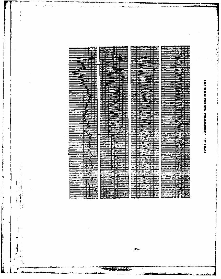
13. Ci.ro.Jnferent.ial walk - Bcrly lot>tion Test ------
14. nesponse to cable'Crossir¥1s -----------
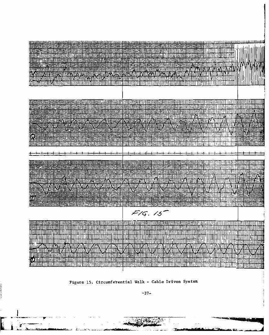
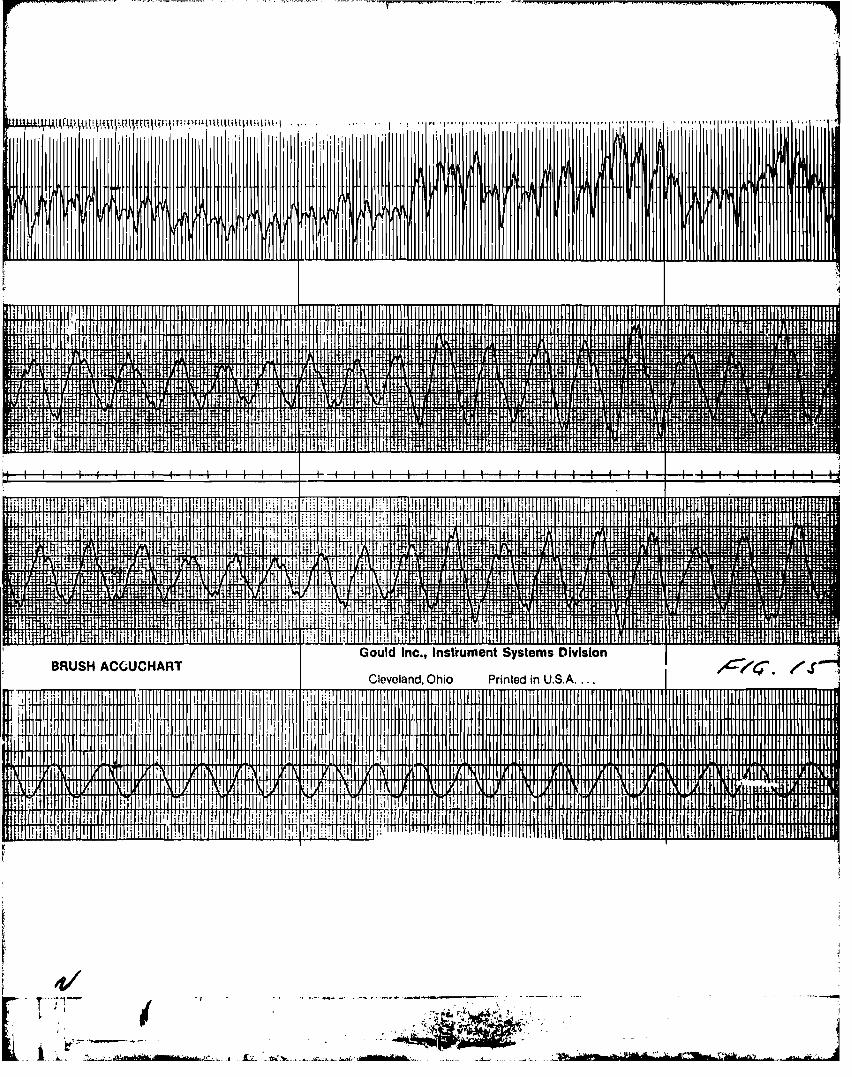
15. Circunferential walk - cable Driven System ---,
16. Ci.rclJnferential walk - Antenna Driven System ----,
11. ()liescent Test -.---------.--------
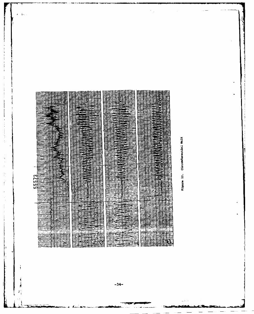
12. Circl.Jnferentia1 walk ----.-----
7. SlJm\i11g Circuits -----.-------------
8. ()lad-ature Circuits --
9. Vector COnpltation Circuits -.---- ,---
10. Moniter Circuit -.------
Figure No.
1. Diqital1y amtro11ed AtterJJatar --------.--
2. Digital Fa:. -------------------
, ..._ 7 tiHbnii 'un ••• r .m? •
iv
.·~~~,i~~¥¥\~,"q. ....
.. G.b' '.. .;: _.'O'-_.:-:I.~~_ .. ,'.~.~,.=tb ten 'rifte· +ed·'~•• ' ~·"··'f l' .. .... ai+b~
!; 'tt.~,~,--,
i_.-,~:,..._.~Wtt" 1_' 1&: -'.:...<1..1 _,~'.:.l
i'-~ ..... ,
EVALUATI otl
BecaUI'e of the val ue of resources, the costs of securl ty personnel,
and the thre~+s of vandal 15m and sabotage, a need exists for an lntruder
detectIon system to protect lsolated hIgh value resources. Present systems
f
1itr,I
i
)
~ .I
suffer severe deflclencles: a hIgh false alarm rate, diffIculty In controlling
the extent and uniformity of the detection zone, and crltlcal set-up procedure••
To overcome these problems a radio fr~quency Intruder detection system concept
has been d~veloped which makes use of a transmitting leaky coax cable, receiving
monopole antennas, and signal processing cirCUitry. This report concentrate,
on the design and development aspects of the signal processIng ctrcultry.
Signal processing circuitry using signal cancellatIon and quadrature detection
technIques was designed, const~ucted and tested. The circuits perfunmed well
and within their design lImits. During the test~ng, the circuits were continually
modlfled and updated so that the present design Is sound and can serve as a
solid foundation for future advanced development.
N' CHOLAS V. KARAS
Project Engineer
v

-rQ
, I·'-r·n _..I~ "--__.•... ~..
1. INTRODUCTION---.. -~This report describes the development of a radio frequency intruder
detection system intended to protect high value individual resourcns.
The work included some modifications of an already existing system as
well as ~he ~evelopment of a new instrument. The mechanism of tha inter-
action between the single radiat~on wire system and the intrude~ h£s not
as yet been fully I1nderstood. Therefv~e, the emphasis in both of the tasks
was placed on the development of a data 9ath~I'in9 research tuol rather than
on the p.oduction of an operational
. The existing instrumentl was
~G2B-77-C-0142 for the Rome Air
Base~>The original intent was to
system•...../
originally developed under contract
Development center at Hanscom Air Fo~ce
demonstrate only the feasibility of an area
intrusion detection system using radiation coaxial cable, but in the continuous
process of data gathering to determine the RF field characteristics of a
single wire intrusion detection ~ystem, the device was also used in conjuction
with other instruments, to make measurements during field operations. In
that application some shor~comin9s were noted. Thereforel.to1fi~th.!instrument more versatile as a research tool some modifications of the
existing circuits as well as some new 4dditions were incorporated into the
port~le transmitter-receiver unit.
~ In parallel 'ith these modifications another Bystem design was
In the single wire system, where the leaky cQaxial cable was driven at one
end while t.he other was terminated by a matched load, the ~plitude of the
envelope of the detected disturbance exihibited co~siderable variation.
-1- r-r:-
(
disturb&n~e originating at the driven end of the cable was ~lways larger
:'1
I.f,I ~
I:I,
II'Ii
i:r:LI
III
than the one originating near the te.rminatic;n. Also, sane shadowing by
the rosources being protected was found to exist. To counteract thelle
problems, a split coaxi~l cable drive with two receiving monopole antenn.11
was considered. The coui.l cable was to be drivfln at. both ends wb,ile a
matched te~ination was to be plac,d at the midpoint between the driven ends.
This was to reduce to some extent the dependance of the disturbance signal
amplitude on the position of the intruder along the cable. To reduce the
shadowing problem two receiving antennas feeding a single receiver through
a signal combiner were considered. Also, considered was a switching arrange-
ment Where the two sides of the coaxial cable would be alternately driven.
This arrangement trgetber with a synchronous detection could provide infor-
mation on the sector in which intrusion was taking place. This project
was carried through the preliminary design stages and then set aside for a
design of an i.nstrument to test some new idea.s on the single wire intruder
detector system.
At the time a new hypothesis2 wap proposed by' Dr. J. L. Poirier of
RACe on the behavior of the RF signals in a radiating cable area intrusion
detection Rystem. The hypothesis was basad on the data qathered during a
series of experiments with a Bingle radiating coaxial cable and a centrally
located single receiving antenna. The findings seemed to indicate that a
receiving systEIII employing a carrier Buppl:ession and a quadrature detection
scheme could eliminate some of the more objectionable features of the
previous approach.
There were considerable variations in the quiescent received signal
:.
jII,'.
-2-
area enclosed by the radiating cable. A relatively small displacement of
strength that depended on the location of the reoeiving antenna within theioj
J
lh
)10, I
0, I
\ . ~'<""'--~-
1 ~..... ~..:Li:;j'..~"d" rO?±*tr.,lJ; 'C"~W'~'" ", ..t:_~_, ...,~~~ ..,_.. ...:-.k" ....:~~
j, j
\
. '4EQiQJ»?".' $ » --
71'S t.t·~b'''· ,...'.... , _. -" ..,..~<,..••.L. .........,:;~trdt'·M'+d~"¥r k••'y ....AWtttM tT~
t~(r
f,,Il
r
,., 1
phase between the distrubance and the quiescent signal. The resulting
oscillations contained zero crossings which represented effective nulls
in the dhturbed RF field. Silrilar dqnal oscillation. were ob.erved
during taa circum!.erentlal walks.) In turn theBe null. produced voltages
at the dbtector below p£eset threshold levels during ~ portion o~ tua
cycle. Thus, at least theoretically, an intruder could approach and
cross the cable without being detected.
To reduce the effect of the larqe oscillations in the detected
disturbance signal caused by an approaching intruder the phase dependent
components had to be elilM-ted from the signal at the detector. For that
purpos9 a quad~ature detection scheme was employed. In addition to the
amplitUde detection a phase detection circuits were also incorporated
~e instrument. No threshold or alarm circuits were included.
In the first part of this report s,ome of the modifications of the
pr<ilviously constructed instrument are described. The circuit diagrams
shown should be viewed in conjunction 'itlith the circuit descriptions
presented in Reference 1. The rest of the report is devoten to the
description of th~ latest instrument. Since the design of the switchable
instrument did not proceed beyond the advanced planning stages no descrip-
Ition of that system is press.ted. r\\
-4- r
-
·'T~I""'""""••••" __""__.'"~"'~,;;.~,;,;;".,,-,,;:;m~"""-;:';"=O:"''''.'M-.~'~...-.&" ~;"~·"·f'rrT.1F ,-.,...1IIiIIii........ ..... _
2. MODIFICATIONS OF THE EXISISTING SYSTEM
The original area Intrusion Detection and Alnrm syatem1 developed
Il
III
I~t,i
in 1977 was il'ltended to demonstrate o'nly the feaaibility of an intruder
detection system employing a leaky coaxial cable an~ a stmple monopole
antenna. During tests designed to determ~ne the RF field characteri.tic.
of such a system the unit was employed to gather data. In that capacity
some shortcomings were noted.
During prolonged circumferential walks the alarm threahold levels
al. ,eared to be changing. Considerable changes in the threshold le-,ela
occurred when several of these walks were repeated within a·short ttme
J
I11
.'
il[1'i',!
"I,!.~
t'II'
I
1.t:
I:.r
I
I A.~
I ,,
L ;.'
of each other. This behaviol was caused by the normal response of the
AGC circuit. The circuit interpreted the rapid but unsymetrical variationa
in the signal strength caused by a person walking around the pertmeter
as a long ~erm s1gnal strength change and tried to adjuat the receiver gain
accordingly. A repeated walk just compounded the probl.m. To correct
this deficiency a switch selectable manual gain control was added to the
circuit. similar probl ~s may be encountered with other systems during
eVbluation and testing, if a manual ~vorid. of the AGC circuits ia not
provided.
In conjunction with this AGC modification a new digitally controlled
~ircuit was constructed. It was intended as a replacement for the existing
highly nonlinear RF atternator within the AGC loop. To keep the ttmQ
constant of the AGC the same at all operating levels the cha~acteri8tic
required lineraization. The control signal to the RF atteunator was shaped
~l -5-.;~
• ~l;
·,.fltt+r.-
I
'---'-"'-i~
............ ,A
-
by a bootstrap circuit. Acceptable, but not invariant ti_ con.tant
'II" achieved throughout the operatinq range. Alao, 4urill9 tha te.t.,
when thQ AGC was dbabled, the ayatem had to be IllAnually a4juat.4 to
I
.
J'\
I", VI
I'I
J
J"..f: II
J \
,/ '
operating point upon a command.
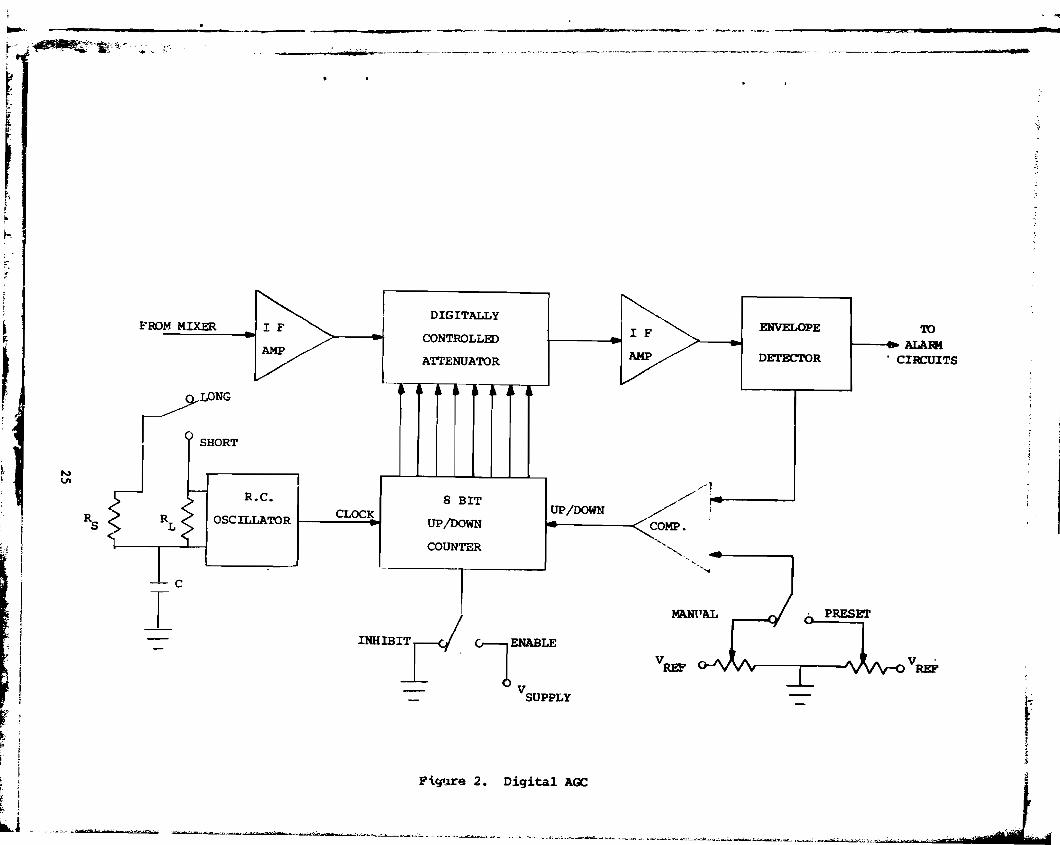
The digitally controlled attenuator ahown in Fiqure. 1 and 2 al~in.te4
these problems. It could be opera':ed over a 64dB range in 0,2548 incr.ant••
An eight bit UP/DOWN counter, drive~ by a clock and controlled by a
comparator maintained the design signal level. Th. reaction time of the
AGe was controlled by the clock I a high frequency signal for initial
adjustment and a low frequency clock for norm.l operation. An inhibit
switch was included to maintain the quie.cent level during the periferal
tes~s walks to establish th~ detection probabilities and/or to .et the
alarm threshold levels. A manual control AOd. \1Il.. al.o retained in the
design. This AGC looV was not installed into the exiating ayatem only
because, at that ttme, the emphasia waa ahifted to the development of an
instrument to teat new idea. on the Bingle wire intruBion detection .yat...
Originally the alarm threshold levels for both the incre.aing an~
the decreasing 'lignal levels due to • diatrubance wez'••et at 3dB with
respect to the quie.cent signal level. They were thought adequate to
dete~t an intruder crossing the radiating cable. In exper~ntation_ith
circumferential walks at various distanc•• from the ~abl. the .etting8 ~re
found to bo r.estrictiv.. Controls we~e provided to .et the laver and
the upper deflection threshold levels independently over .ero to 6dB range.
This modification of the existing comparator circuit ia .hown in Fi~e 3.
-6-
• _1
1iI.

To test the characteristics of the system ~ith a buried coaxial
radi"tinq cable, the tranaitter pow.r wa. incr.ased frc:. 10 to :200 IN.
A caac:ad. of AVANTElt r,PD - 401, 402 and 403 RF _rlifiu. with a total
gain of 3~B replaced the Q-BIT QB-6l4 am~lifier to g~ovid. the nec....ry
powe.c boost.
The batte.t'y configuration and its output voltage was chanqed to 24V
to accOlllDOdate the power requirements of the new RF amplifier. A battery
charger, shewn itl Figur13 4, was also added. Two battery pack. in the
original systam were damaqed during field operations due to massive
i
1III
ov.rcharges. The charger allowed for a continuous operation of the system
free an external pov.er »eurce and an unlimited charging time without
damage to the batteries. The battery voltago and the three internal
regulator output v.:.oltages could be monitored on a panel meter. The
incoming RF signal level and the AGe voltage could a180 be selected for
display on the same meter.
These additions and modifications improved the overall usefulness
and reliability of the instrum'4{"-, The digita~ AGe Loop , although not
·1
..)1. "\
,J I L ......
. . t'''-'-~-~~_ ........... ~_ ~"Ih- 4Tf'ed_ _ t
actually installed into th~ systar" could further contribute to the
improvem"nt if Lncoxporr.ced in a similar area intrusion detection and
alarm system.
-7-
Ij
A. General Description
The second Area Intrusion Detection System (AIDS) was designed
to reflect the thinJd.ng at that time on the behavior of the RF field
3. AREA IN'l'IWSION DETECTION SYSTEM II
pointed out in the introduction of this report, the AGe employed in the
to be counterproductive in the stabilization of the alarm threshold levels.
Therefore, it waa replaced by a quiescent signal cancellation circuit. In
near and within the area encircled by a single radiation cable. As
rec~ived signal path, as was the case in the first system, was thought
addition, a quadrature detection of the disturbance signal was used to
elUninate the phase related variations in the detected signal. Since the
transmi~ter-receivQrunit was envisioned to be u~ed as a research tool
rather than as an alarm systen, the circuits associated with the set~ings
of the decision thresholds and the alarm were not incorporated in the design.
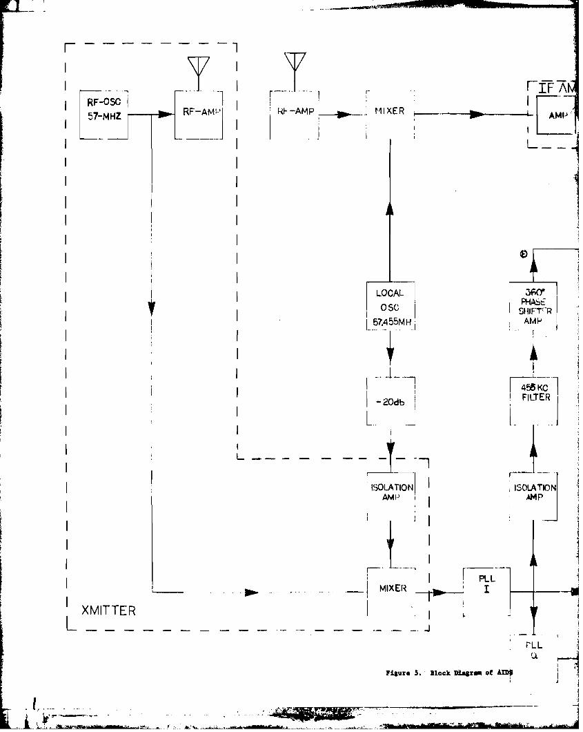
A block diagram cf th", syst.em is shown in Figure 5. The RF portion
lt!
irr
! ,I
'I
I
l ',il '\
! II', ~
I
I•I
of the system operated at 57 MHz while the other operations were
performed at an intermidate frequency of 455 kHz and a base band of
o to 10Hz.
A crystal controlled oscillator and an amplifier produced
approximately 250 mw of RF signal to drive the radiating cable or the
antenna, if desireti. A small port,i.on of the oscillator oui:put was also
used to power a mixer where the 455 KHz intermediate frequency reference
signal was generated. For that purpose a crystal controlled local
oscillator of 57.455 MHz was uaed. The output of the same local oscillator
~.'
was alao employed to drive another mixer to produce the IF signal from
t..:'~e received and amplified RF•
.J,/ j
·f' .~
) ~ :-8-
I • t" ._.~.'--" t+oWrtb'iidiiie _ dr'"
, ,.:p:a $
'••H·~
III
.I
'. ,--,""w'" ~"'.',-"'~'"ldIJ~_._
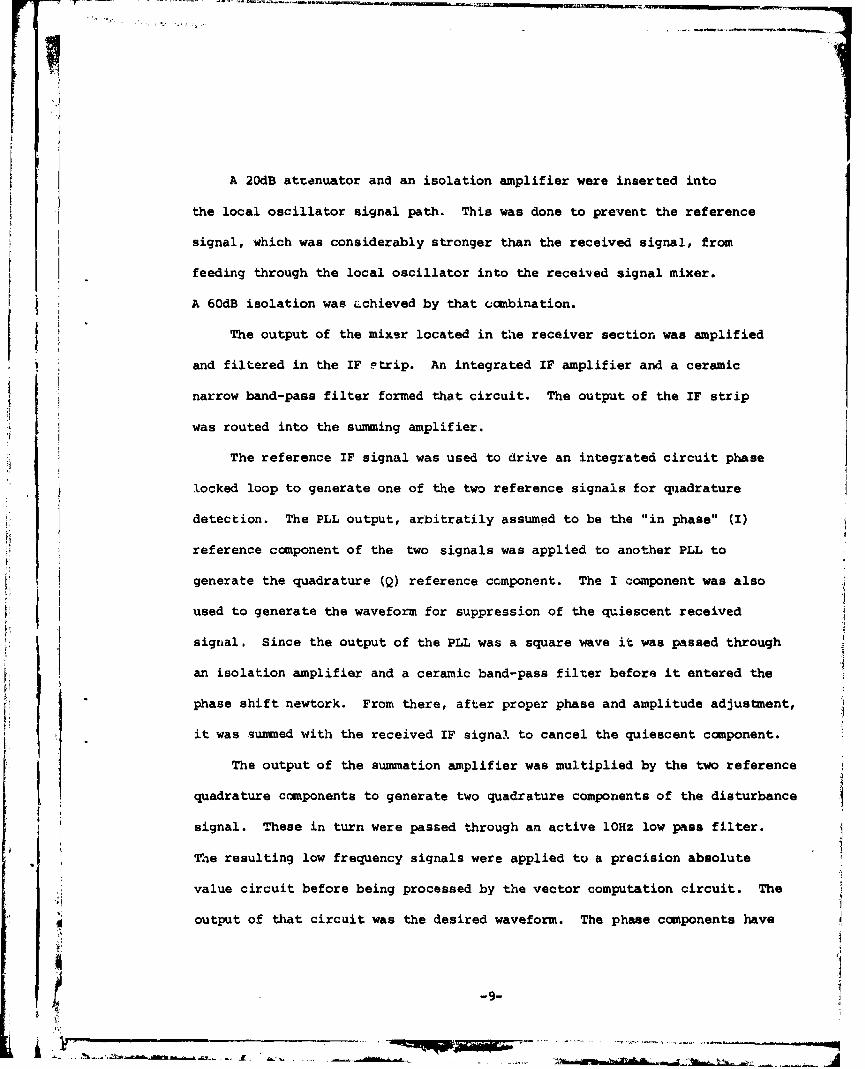
A 20dB ate~nuator and an isolation amplifier were inserted into
the local oscillator signal path. This ~as done to prevent the reference
signal, which was considerably stronger than the received signal, from
feeding through the local oscillator into the recei'V'ed signal mixer.
A 60dB isolation was Lchieved by that ~ombination.
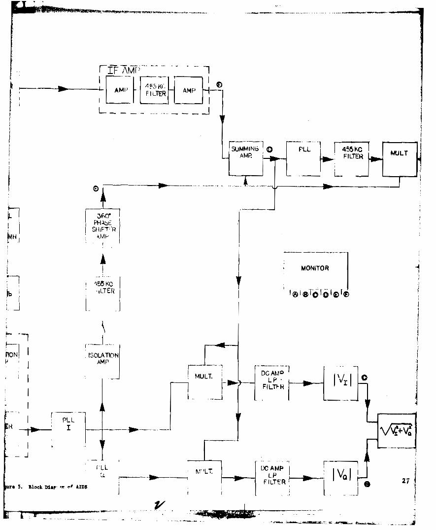
The output of the mix~r located in t~e receiver section was amplified
and filtered in the IF ~trip. An integrated IF amplifier and a ceramic
narrow band-pass filter formed that circuit. The output of the IF strip
was routed into the summing amplifier.
The reference IF signal was used to drive an integrated circuit phase
locked loop to generate one of the two reference signals for ~ladrature
detection. The PLL output, arbitratily assum~d to be the "in phase" (I)
reference canponent of the two signals was applied to another PLL to
generate the quadrature (Q) reference component. The I component was also
used to generate the waveform for suppression of the ~iescent received
signal. Since the output of the PLL was a square wave it ",as passed through
an isolation amplifier and a ceramic band-pass filter before it entered the
phase shift n~wtork. From there, after proper phase and amplitude adjustment,
it was ~wrmed with the received IF signa~. to cancel the quiescent canponent.
The output of the summation amplifier was mUltiplied by the two reference
quadrature components to generate t~o quadrature components of the disturbance
signal. These in turn were passed through an active 10Hz low pass filter •
~1e resulting low frequency signals were applied to a precision absolute
,]j!"
I~,~
output of that circuit ~as the desired waveform. The phase canponents have
value circuit before being processed by the vector computation circuit. The
...: ..
-9-
4L-l( #1ilc p";; -_.~' ......_,
·-'fc'···).······_............ ····.'J.VJf.., _"._. ~
h1W: ·'ttn fNil,.e·'M-" ><["6 ~·lI'l!~.-~,.~~~
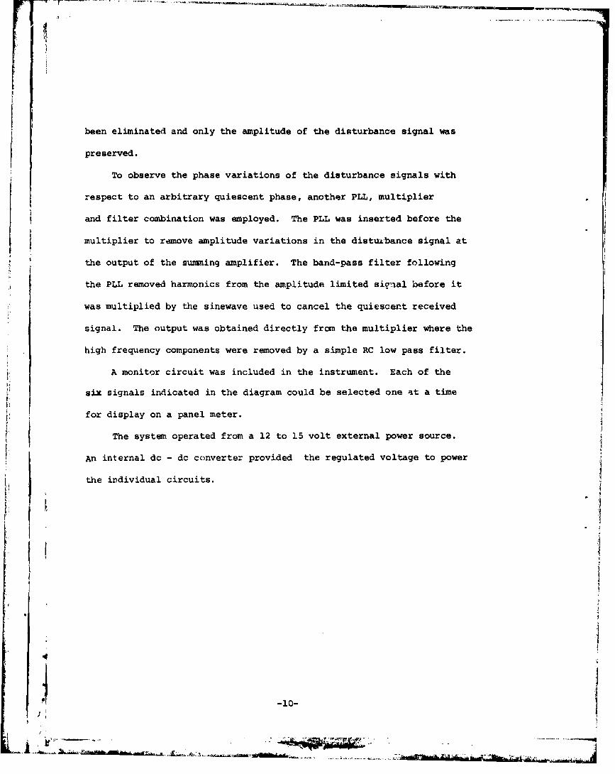
been eliminated and only the amplitude of the disturbance signal was
preserved.
To observe the phase variations of the disturbance signals with
respect to an arbitrary quiescent phase, another PLL, mUltiplier
and filter combination was employed. The PLL was inserted before the
multiplier to rdmove amplitude variations in the distu~bance signal at
the output of the summing amplifier. The band-pass filter following
the PLL removed harmonics from the amplitude limited sig'.lal hefore it
was multiplied by the sinewave used to cancel the quiescer.t received
signal. The output was obtained directly from the multiplier where the
high frequency components were removed by a simple RC low pass filter.
A monitor circuit was included in the instrument. Each of the
six signals indicated in the diagram could be selected one ~t a time
for display on a panel meter.
The system operated from a 12 to 15 volt external power source.
An internal dc - dc converter provided the regulated voltage to power
J II
the individual circuits.
-10-
',1
j':11a
j
I.J
1
1\
_I""'II'-~.'..-r--'."-'1",
II!
·1
I,
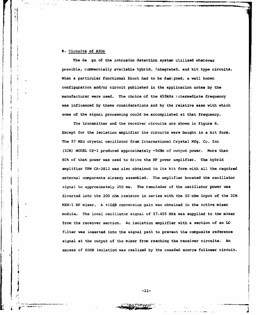
B. Circuits of AIDS
The de .gn of the intrusion detection system utilized wherever
possible, ~ommercially available hybrid, integrated, and kit type circuits.
When a particular functional bloc): had to be des~"lned, a well known
configuration and/or circuit published in the applicacion notes by the
manufacturer were used. The choice of the 455kHz '.L:.termediate frequency
was influenced by these considerations and by the relative ease with which
some of the signal processing could be accomplished at that frequency.
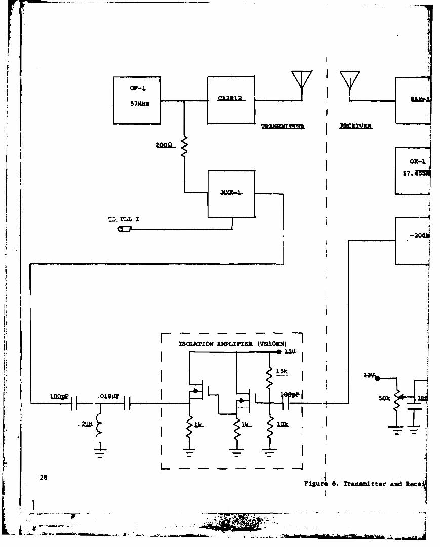
The transmitter and the receiver circuits are shown in Figure 6.
Except for the isolation amplifier the circuits were bought in a kit form.
The 57 MHz crystal oscillator from International Crystal Mfg. C~. Inc
-11-
...._--j. ...;~..!.r,;:_"-~"'I"",- .,"_
filter was inserted into the signal path to prevent the composite reference
signal at the output of the mixer from reaching. the receiver circuits. An
excess of 60dB isolation was realized by the casaded source follower circuit.
module. The local oscillator signal of 57.455 MHz was supplied to the mixer
signal to approximately 250 mw. The remainder of the oscillator power ~as
~~X-l RF mixer. A +lOdB conversion gain was obtained in the ~ctive mixer
from the receiver section. An isolation amplifier with a section of an LC
external components already assembled. The amplifier boosted the oscillator
diverted into the 200 ohm resistor in series with the 50'ohnl input of the ICM
80\ of that power was used to drive the RF power amplifier. The hybrid
amplifier TRW CA-28l2 was also obtained in its kit form with all the required
(IeM) MODEL OF-l produced approximately -5dBm of output power. More than
.' \ ._._-._-_.---_.._----_...
I IIIII
l;,\f';fft,..
rI!!.,.,
..._ ... ' ',..~...,,-,._~_ ..._~~.• ....,..--.:=-~._~~>~·_Y·=--·~""""""""·""'=u.> """"'.....__...... ......""","_~_
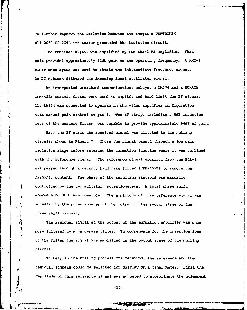
To further improve the isolation between the stages a TEKTRONIX
011-0059-02 20dB attenuator preceeded the isolation circuit.
The received signal was amplified by ICM SAX-l RF amplifier. That
unit provided approximately 12db gain at the operating frequency. A MXX-l
mixer once again was used to obtain the intermediate frequency signal.
An LC network filtered the incoming local oscillator signal.
An intergrated brOadband communications subsystem LM374 and a MONATA
CFM-455F ceramic filter were used to amplify and band limit the IF signal.
The LM374 was connected to operate in the video amplifier configuration
with manual gain control at pin 1. The IF strip, including a 6dB insertion
loss of the ceramic filter, was capable to provide approximately 64dB of gain.
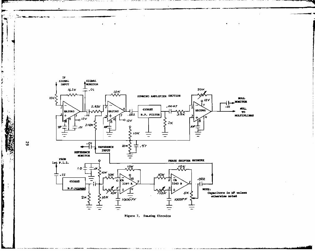
From the IF strip the received signal was directed to the nulling
b"
circuits shown in Figure 7. There the signal passed through a low gain
isolation stage before entering the summation junction where it was combined
with the reference oignal. The reference signal obtained from the PLL-l
.i1
1.~J
.J
1
was passed through a ceramic band pass filter (CEM-455F) to remove the
harmonic content. The phase of the resulting sinusoid was manually
controlled by the two multiturn potentiometers. A total phase shift
approaching 360 0 was possible. The amplitude of this reference signal was
adjusted by the potentiometer at the output of the second stage of the
phase shift circuit.
The residual signal at the output of the summation amplifier was once
more filtered by a band-pass filter. To compensate for the inser'tion loss
of the filter the signal was amplified in the output stage of the nUlling
circuit.
To help in the nulling process the received, the reference and the
residual signals could be selected for display on a panel meter. First the
amplitude of this reference signal was adjusted to approxlmate ~he quiesc~nt
-12-
iiliiia=-~---~~Jir(,!i;4(w,';";91i""n·'t ) eM W .."., ....... d3D-"m Tnssn..
.:,~~·e.¥(Whib . i.r··'~·'" WE .. ""-'f ...... ,aJ~••=-
ee co' ~~.. _... ,.• ~"."., ...... ",,>.,.~
.I :I " ~,\ 7"" .• ...-.-..-.••- 'CW_
~=.i.._ .:A...."L•. 1\ ,'M I':~_' b
r ,r
~.'!'.1:'j,.....
, .
r III
f. 1
r '1! '~
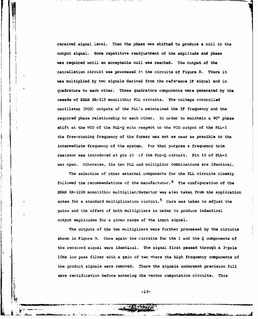
received signal level. Then the phase was shifted to produce a null in the
output signal. Some repetitive readjustment of the amplitude and phase
was required until an acceptable null was reached. Tha output of the
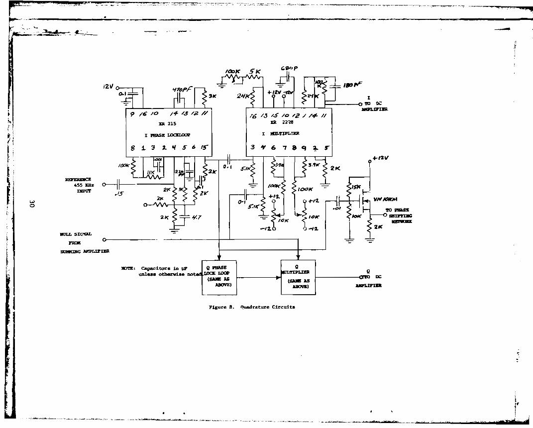
cancellation circuit was processed i~ the circuits of Figure 8. There it
was multiplied by two signals derived from the reference IF signal and in
~adratur. to each other. These -=lUadrature canponents were generated by the
casade of EXAR XR-21S monolithic PLL circuits. The voltage controlled
o~cillator (VCO} outputs of the PLL's maintained the IF frequency and the
required phase relationship to each other. In order to maintain a 90° phase
shift at the VCO of the PLL-Q witn respect to the VCO output of the PLL-I
the free-running frequency of the former was set as near as possible to the
intermediate frequency of the system. For that purpose a frequency trim
resistor was introduGed at pin 10 cf the PLL-Q circuit. Pin 10 of PLL-I
was open. Otherwise, the two PLL and multiplier combinations are identical.
The selection of other external components for the PLL circuits closely
followed the recommendations of the manufactur~r.4 The configuration of ther •,
t i
I:"t:fE;~ ,
I'
I,!
\I•i
EXAR XR-2228 monolithic multiplier/detector was also taken from the application
notes for a standard multiplication circuit. S Care was taken to adjust the
gains and the offset of both mUltipliers in order to produce indentical
output amplitudes for a given range of the input signal.
The outputs of the two mUltipliers were further processed by the circuits
shown in Fig~re 9. Once again the circuits f~ the I and the Q components of
the received signal were ident~cal. The signal first passed through a 3-pole
10HZ low pass filter with a gain of two where the high frequency components of
the product signals were removed. There the signals underwent precision full
wave rectification before entering the vector computation circuits. ~his
__til----_._'------_.«as
, j~,,--.,~ '.,~-- " ..-_.. ,---.....__..._...._------~ ...~~----......-~---~ ......_---_-......"~" ..,.~---- ....-- ....--.-r--
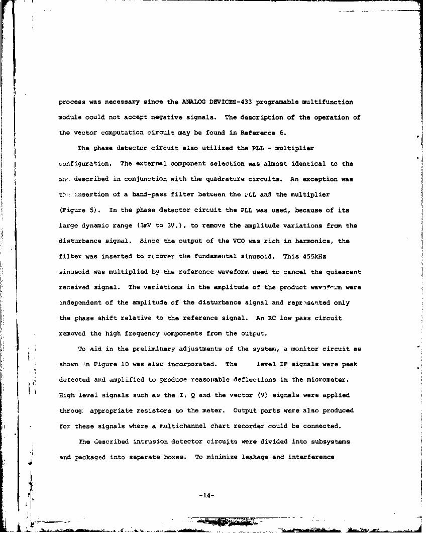
process was necessary since the ANALOG DEVICES-433 prQgramable multifunction
module could not accept negative signals. The description of the operation of
the vector computation circuit may be found in Refererce 6.
The phase detector circuit also utilized the PLL - multiplier
configuration. The external component selection was almost identical to the
on'. described in conjunction with the quadrature circuits. An exception was
t~1': i.nsertion ot a band-pass filter bet...~en tho l:'LL and the mUltiplier
(Figure 5). In the phase detector circuit the PLL was used, because of its
large dynamic range (3mV to 3V.), to remove the amplitude variations fram the
disturbance signal. Since the output of the VCO was rich in harmonics, the
filtE'!r was inserted to rL;;Over the fundamental sinusoid. This 455kHz
'j. l
l
11ijJ
111I,!
-14-
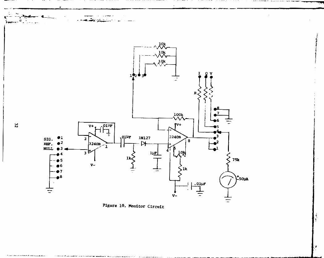
remov6d the high frequency components from the output.
..
,
±ttw•.A
level IF signals were peak
throug1 appropriate resistors to the meter. Output ports were also produced
The ~escribed intrusion detector circu~ts were divided into subsystems
and packaged into separate boxes. To minimize leakage and interference
To aid in the preliminary adjustments of the system, a monitor circuit as
High level signals such as the I, Q and the vector (V) signals were applied
for these signals where a multichannel chart recorder could be connected.
shown 1n Figure 10 was also incorporated. The
the phase shift relative to the reference signal. An RC low pass circuit
independent of the amplitude of the disturbance signal and re~~s6nted only
detected and amplified to produce reasonable deflections in the micrometer •
sinusoid was mUltiplied by the reference waveform used to cancel the quiescent
received signal. The variations in the amplitude of the product wav~~~~~ were
~.l
Hi,-r:~;,
I~ >,l
I:r:
I,~
li~ It;
I .
I Ii ~, I
II
'I
i'j
J
l•) I,:
problems interconnections betwe.n the subsystems were made through RF
connectors and shielded cables. Servicing or modifying the eeparate
circuit blocks was relatively simple. New functional blocks could
easily be added or rfHnoved to try some new configurations. The subsystems
were mO'JIlted in a metal instrument carrying case for transportation.
:1,j
i! J'! .1"~ :
,I'
]II
iiI,i:
r,,;
,
I: I li
\!~
j
L jl
I4
jj,:t
J :'t -----------_...._~~ .......,,- -..........~.< ..,,-,....."'-..,.......~_..
j , Jr' -::- ...--..-:-- ~ - .__.......Ls,....L . ." ",'1 dNt'rle.ft _ ' +rl £i..~ .. _..
-15-
_ w_
rr
--'---, -----
..........._-~----_ .. ·..··_.. ·_,··-·---11
c. Perfoxm&nce
Several t~8t. wer.e conducted at \~e RACC test .~~ at Han.com Air
~
HitI
II1..
II
I
\
.I ,_n PIR
Force Base to evaluate the performance of the intru.ion detection 8y.t~.
The tests were primarily intended to establish the validity of the system
design concepts and to observe its performance in a field enviroment.
Due to time limitations trope_ed by the approaching end of the contract
onl:.' ,:;ualita,tive observations were made on' the (lystem behavior. These
led to ~ discovery of a f~w minor defficiences, mostly in the alignment
procedures, which were correcte~. No attempt was made to gather
quantitative data reg"'.rding the variations in the disturbance signal
caused by various system dep~~yment configurations or due to the position
and lor size of the intruder.
The ~ests were conductod usi~g Type 28~ radiating coaxial ca~le
manuft.c-tured by the Tim~s Wire and Cable Co. A monopole antenna mounted
on a g.lound plane wa..l placed r.uar the center .Jf a 44 meter diameter
cirr:le formed by the cable. rhe "llonopola was st,hi:i.i~3d against wir.d by
four nonconducting guy wires attacned to the ground plane. l'Jo attempt
was made to optimize U1e ~ntenna for the op.ra~ion at 5?MHz. When
measured clle ov-"ralJ. signal path loss C'f the system rnnged betwec.•1 85 to
94d}:1 en several occasior:s &:'-5 ulldel.· differing cable deployment. During
each of the tests ~~e system was operated at quiescent conditions for long
periods at a time to observe any spur iOU3 deviat.ions of the output fran
a preset value that could be interpreted as a false alarm. On each of
the occasions there ~as vehicular as well a. pedestrian traffic on a road
approximately 15 met~rs from the radiating cable. Only or.ce a small but
-16-
_: .'1:"0
I
r
r
t
--..... r
I
I1\
f
I
I, I
f )~
.. -. -" _.__ ... _---_ .._._-----_._- ----~--
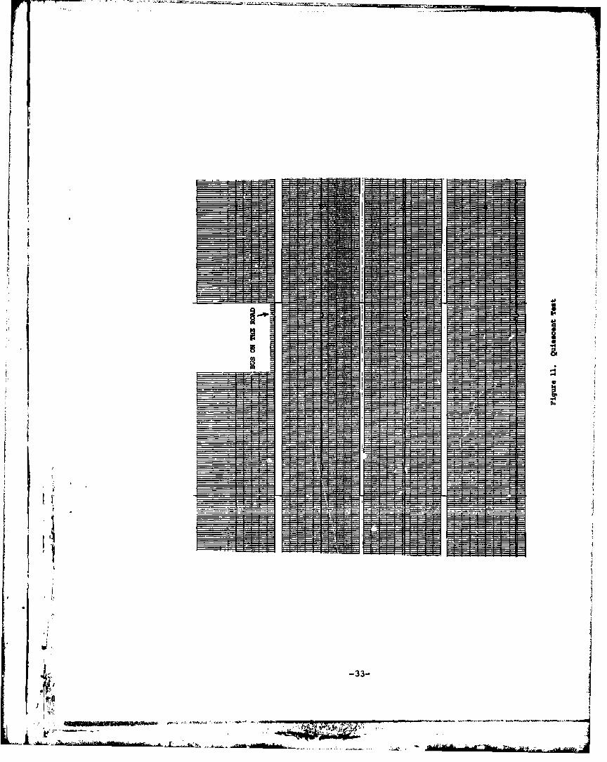
significant deviation occurred from the quie.c.nt leval which coincided with
a bus passing the test site. A portion ot that quie.cent t ••t i ••hown in
Figure 11. The top trace represents the vector signal. Th~ two lo~r
ones show the Q and I components respectivelv, while the very bottan trace
representR the phase detector output. In thia figure and in all that
follow the ch~nnel deflections of the chart recroder were approximately
set to 20omV/cm for the vector signal and 50omv/cm for the other signal••
It must be emphasized that these were only very approximate settings in
which th~ vernier gain controls Were ignored. Therefore, the diviation
of the signals trom their quiescent v~lues should be viewed in conjunction
with other traces Where the disturbances by a person near the cable are
shown. The deviation coinciding with the passing of the bu. was less
than 10' of the minimum deflection observed in any of the circumferential
wQlks. It should be noted that other traffic was also present during the
time period represented by the traces. Also, wind gusts e.timated in exce••
of 50 km/hr were also present during that particular ~\ie.c.nt signal test.
A~ may be observed the wind and the traffic ~ad no significant effect on
the system.
A quadrature alignment check and a circumf~rential wal} rusults are
shown in Figure 12. The traces from top to bottom represent the vector,
Q, I and phase signals respectively. The left hand portion of the figure
shows the vector and the quadrature signals during an aligrnnent check.
After each deployment the system was exercised to confirm it. propor
operation. One of these tests involved a check for balance of th$ two
quadrature components < A phase deviation of only a few degree. from a
-17-
true quadrature introduces substantial error in the camputed vector signal.
'~.n drivon by sinu.~ijs out of quadrature, the vector ~ignal exhibits
error voltagG at twice the frequency of 'he input signal. Amplitude
differences and de offset voltages also contribute to the output errors
with de and ac components. In this test a signal generator was tuned to
I.III
iI
'iI,
"'"
.~J i ,!",ll!
if IF frequency of the system. Its output was applied to the sUJllltd..ng
amplifier with the cancellation signal disconnected. Two quadrature
components were generated in the PLL-multiplier circuits. While the
oscillator signal slOWly drifted within the base of 0 to 10Hz from the
system 7.F signal a vector signal was obtained. The magnitude of the ripple
in that signal was a good indication of the balance in the quadrature
circuit under dynamic conditions. The phase circuit was not connected
during the test shown in the figure.
The right hand sile of the fig~re shows the results of a circumferential
walk taken immediately after the system check. The cable was approached
from the end terminated in a load. The walker then ~oceeded towards the
end connected to the transmitter. Thus the increasing received signal
strength when the lble losses deeredse. The envelopes of the vector as
well as of the two qu~drature components show the int9rference pattern
between the radiated and the surface wav~ signals. It was expected that
the vflotor signal would be a. relatively smoo'i:h envelope of the quadrature
components. Therefore, when the fine noise like structure was first
observed it w~s thought to be caused by the signal processing circuits.
Although the quadrature balance teats &hows some imperfections in the vector
signal, the variations in the signal obrained during the circumferential
WAlk could not be attributed to the imperfections of the quadrature
-18-
. J1
I1
!11
jl1I
~~
.I.. • Irw 1 ni .r.'"...,~.~-
1. i..,~I1""'''' 'M
Ell;\
_no' :.J3t tnT em' "t sm. re'.it..· "",. Otwi~
flt.
f[
j
-. ,
I
i110
.".. ,
detActor. It was concluded that the ~'ine stn\cture was caused by the motion
of the body, its arms and legs. To test this ~slumption another walk wal
taken. The results a~e presented in Figure lJ. During the first helf of
the walk the II intruder II pruduces minim.m\ IlIOt:lon by keeping his IorIltl Io.gainst
the body And by taking small robot li~e steps. The fine atrUQture in the
vector signal was redllced considerably. The body motion during each small
step may be observed in portions of the quadrature components. In the second
half of the walk normal motions were res\uned as evidenced by the increase
in th~ amplitude of the higher frequency components.
Figure 14 shows the respon&e of the s~stem to an intruder crossing
the cable and to the motion within the encircled area. First, the radiating
cable was crossed at the high power end near the feed line. Then the
intruder passed within approximately one meter of the receiving antenna and
left the encircled area approximately 1800 from the entrance point. On
the return path the cable was crosDed near the place where the exit hal been
made. Now the antenna was passed on ~h~ other side and the exist was made at
the termination of the coaxial cable. The disturbances at the 1800 crossings
were much more pronQunced then at the both ends of the cable. This, of course,
was a pure coincidence for this crossing. But it points out the fact that
a large variation in the disturbance signal amplitUde can be ~xpected,
making it difficult to chcoae the alarm threshold levels to inl\ure detection
while minimizing the false alarm rate from a ne~rby activity. It should be
noted that the phase detector outputs showed less amplitude variation in
the cable crossings but were more sensitive to the activity near the
receiving antenna.
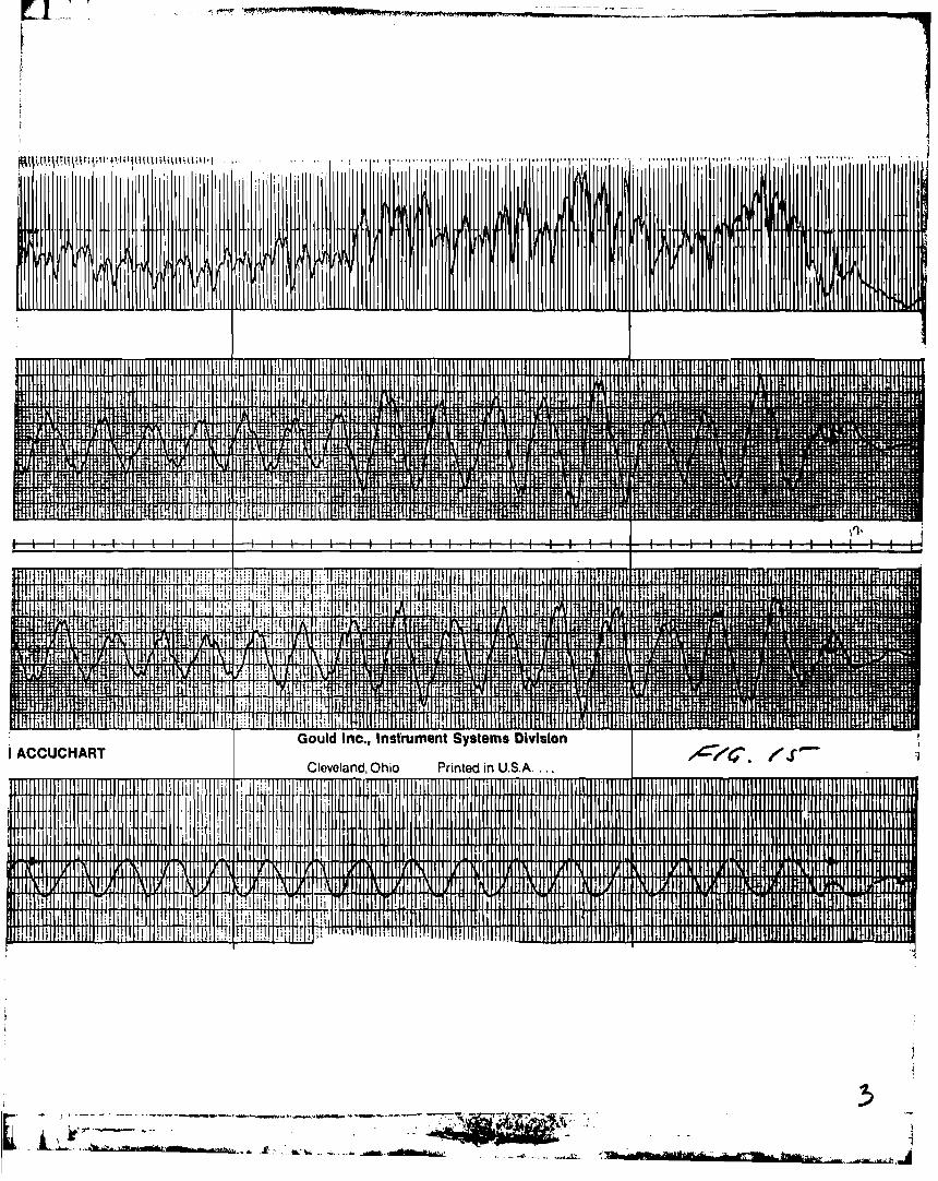
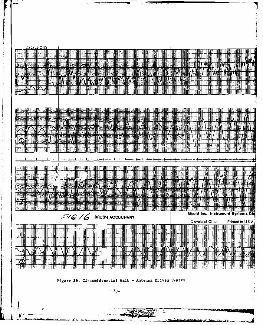
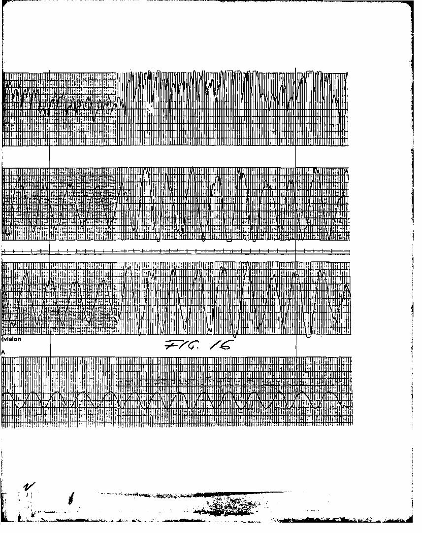
Figures 15 and 16 represent two circumferential walks with an expended
-19-
tj~e scale to show in more detail the tine structure in the wavefoxms.
16 the walk wa. made while the antenna was connected t~ radiate and the
cable was used to reedve the signal. In this conU9\lX'aUon there wae an
increaae in the recoived power. ~heretore, the .Yltem wal readjueted to
cancel the quiescent signal. Alao, dur ing both of th.... walk. the pha.e
detector circuits were driven directly from the reterence PLL and not trom
the cancellation signal. For that reason there were no djfterence. in the
amplitude of the phaae detector output for the two configuration.. Although
the amplitudes differed, the general shape in the envelope of the vector
signals were preserved. The signal amplitude in the antenna driven ca.e
was limited by the chart recorder and not by the signal proce••ing circuit•
. 1
j
l1l
CSKU a
-20-
.IIIIii ~_"'_l'tIi"""""NI b$A'~_.\""' '-'-'-"l'Y_""_II:S••••••;;;b;-·...- ...."...._--..."I:'~--_ ..,---'.~J,\L
- . IFu ••uu.M _,
--~--------""''''-'''----------------_'l'''''Il'_
D. Conclusion-_.""-An intrusion detection system using quiescent signal cancellation
and quadrature detection was designed, constructed and tested. It was
intended to be an instr~ent for observation and dAta gathering rather
~~an for field deployment to protect high value individual resources.
Time ltmita~ions curtailed the intended testing program to several per-
formance evaluation tests in which the emphasis was placed on qualitative
obse.vations to identify areas where further refinement in the system
concept and/or circuits would be necessary.
From these tests it may be concluded that the system performed well
and within its design limits. The indirect gain control by cancellation
of the quiescent signal while leaving the disturbance component unaffected
presented no difficulties. The manual adjustment of the reference signal
phase and amplitude to achieve the desired cancellation proved to be
somewhat Lnccnvend.enti, It could be replaced by an autcmated prJcess. The
quadrature deteotion scheme required some attention and care in balancing
of the quadrature circuit components to achieve the desired results at the
connections. The proximity ot the transmitter to the receiver also
output of the vector computation circuit. A more serious problem was~
I!1i11;I,jj
)
,,i
1-1
1jjJ1
Humans
No substantial
Vehicles at lS meters did
. -~ .. _.-_...... ,.."..- ......_--~.............__..._-"......-'. ~
..~....iidHt ri' d ....- ..~.......Mld~
-21-
'~f:ltf~• _. :l\>",' '1'., ',' / • " ;'!'". _
t_tns,~\...
The field tests indicated that the system was not very susceptible
to an activity away from the radiating cable.
could not ',e detected at distances in excess of 3 meters.
contrihuted to the leakage problem.
presented by the leakage of the reference signals from the transmitter
into the received signal circuits through the common local oscillator
'not produce a signal that could be interpreted as an intrusion.
,t
!II
i ~ ,I! J
I: - •., ................,_.._ ... -.. ~,..." ... -_.
1-1 j ,! jr' 7" ----,.- ~ _. .
lIl..-..._j~--,-~wtG ..,,,1t~ =. $ t \l~\w,
._~ ,. '''- .-..- "' ..----- ------.-----------------_._-
deviation from the quiescent level was ever detected that was not caused
by a person crossing or passing close to the radiating cable. Activity
within the enclosed area and especially near the rec~iving antenna produced
detectable disturbance levels..1lJ
".,"
It
The quadrature detector output showed much more activity than expected.
The body motion produced higher frequency components superimposed upon
the dc level representing the amplitude envelope of the disturbance caused
by a circumferential walk. The envelope also varied somewhat more than
expected. There appeared to be less variation in the amplitude of the
detected disturbance signal caused by deployment than in a system using
~1111
J,J1
t-'a AGe. It should be noted that this is only a qualitative obRervation.
Comparative and quantitative tests should be conducted to determine if
indeed this is true.
threshold levels •
be eliminated. On the other hand, the nulls in the detected threshold
reappear. There may exist a detection method, which not unlike the
-22-
=q "aX $ iF - .._' - ~;:;l!':Z~:',__. . c ;e,j::C:. ..4"."'., __, ~ ........ 1.-' $', . ...~O~ ••• _ ,._~o- ...2J~itgilllllll.__.II...-...i:I.=.....,.;;;IIIii::;;..~c·;.-Ili;..l;;;ilil:~*...o......._~_~....
The data from the phase detector seems to offer an alternative to the
quadrature method, could fill in the nulls to insure detection with stable
voltage which have been elimated by the quadrature detection scheme would
as the disturbance signals the amplitude related threshold problems could
amplitude based detection system. By hard limiting the reference as well
I •I
Jl
1 ~".C,
I r'-
t ' . _,"'8_' ,...-c-r.. , ,,~,_.' .....~....... ..
.,"'...............,-~~, ....~ !I'_tHe '. .e: .-...L-....... ?~_._:;, ~t d~
I•
" ,
IIt',r!II
II4
r
t'
J
t
,t
I~ !"~:i
I'.
Itt
~ 1
<,
~... 1
1,1!
REFERENCES
1. Rochefort, J.S., Sukys, R. and poirier, N.C.(1978), "An Area Intrusion Detection and Alarm System,"RADC-TR-78-258, Fir~l Report, Northeastern University, A0632~9.
2. poirier, J .L. Prtvate COIl1I\unication, (1978)
3. poirier, J.L., Karas, N.V. Antonucci, J.A., Szczytko,M. (1977)"VHF Intrusion Detection" A Technique for Parked Aircraft,"RADC-T,R-77-384, In-House Report, Rome Air Development Center, A051144.
4. ,"Phase-Locked Loop Data BOOk," (1978) Exar Integrated Systems, Inc.
s. "Monolithic MUltiplior/Decoder." (1979) Exar Integrated System, Inc.
o. Sheingold, D.H. (1974), "Noulonear Circuits Handbook."Analog Devices Inc.
PERSONNEL
A list of engineers who contributed to the work reported is given belO'.,:
J. Spencer Rochefort, Professor of Electrical Engineering,Co-Principal Investigator
Raimundas Sukys, Senior Research AssociateCo-Principal Investigator
Norman C. Poirier, Research Associate, Engineer
RELATED CONTRACTS & PUBLICATIONS
F19628-77-C-0142, 15 May 1977 through 15 February 1978
F19628-78-C-0160, 18 september 1978 through 3 December 1979
Rochefort, J.S., Sukys, R. and Poirier, N.C. (1978),"An Area Intrusion Detection and Alarm System." RADC-TR-78-258
,I,1j1
ij
23
.....-_..._-----.._--_.- ~.,~. --..",
• \ .Jt~:;- ..--.",,--~~''-...I~~~__,~ IT "'.,Vj,I.t+ '_ &ri"'P ,...---Au ....L~~_ <~~...._'"'. ,~~'-'--'~t
.:?]ZIPI..riJf€?Jjk~;·. - ~
~lt t "{. 1_"~_1'~_~ _._ .... u. _,u_.,-_.<.l_~":"'".....~ ... ,· ~",_1:'~~
Figure 1. Digitally Controlled Attenuator
PUT
i-
RELAy
MAGNACRAFT
W172DIP-7(2 PER CELL)
.."'"C-~··-·:;:~-: ,-.";.;o."c·"",,.-..-_y,,--.,. ... - - .•"~..,....".,..,.,,~ .".....~ .. , "!!!"'J;H;Z; 4;;'1----.......-.. - .....-,._ ..~_.- ------
I .LV .L~ UA.LV.c~
--~-----------_..'--_ ..
4.._...:_
-CELL Al A2 A3 A4 AS A6 A7 A8
Rl 34750 17380 870U 436S' 2210 1160 68.8S' 52.60 -R2 1.440 2.880 5.770 11.£.10 23.80 52.80 153.8n 9950
R3 34750 1738Q 870n 436S' ~2H2 116 0 68.80 52.60
CELL Al A2 A3 A4 . AS A6 A7 A8-
7T 60 ~~ 1 4 7r. 1~~
~_I _"l-i ?~ - ..
84 144~ 8 4_ 144t
iR2AAJ\
I
IVVv!
'> <>
IR.l R3;>
l16.dB Il,.dB I- ------ -
0.25dB 0.50dl 1.OdB 2.OdB 4.0dB 8.OdB
l
N
"""
J!!t:~:c,. 9AC$i- CE4S;' .. ' ,., 44941>, .. *-...", %. ""'fF__~~~~,-'T-~~"""-~,,..._,,,,,,,,,_,::~~~::-:,, ,_: ..:.:~_-:,,:_,
t
~. ~.r\- --.~
: t
b1·~.V~
i--
ft
,~.~It'I, ,1 .. ,L.
\
---...ll ..-...~*j: "."%2'=.$' • ',£'~~-"~._........"...~.;", .......-_.. f'~~~~"... j,';~ __ "" __" __ .,,__ ,,,__
I! 1I •
• f J
.~ .J.J__ .. __JIi
~}
...,.--~._~-. --'._--.-... - --- ..--_._---- --~---~._ ....-...--------.-..----_._------' ,.,,,--.-.-.- ...
'{',.• .
.....-_~._ __ _ .... _, .._' . ~. _.__ _L'~-' - •.e.,. - ..""~.1
M'''' ~
~
F-'~" .;:r-:-'~~~
h;
h
:7.it
•
t
FROM MIXER
AMP
~LONG
I 9 SHORT
DIGITALLY
CONTROLLED
ATTENUATOR
I FENVELOPE
DETECTOR
TOI .. ALARM
CIBCUITS
1JDigital AGe ~
arl 1. 1 a e ~ ~ ~~_-" ~..... ~ ~~_~ .- ~~ .... _.~".. __ ,....,~"""'... ""-•••--'-.~--',.. __.... :....s....&..~.,...----..,..........._ ••~..".'" or. "rj¥ "'c-z'hf - H
l~
r!j.~
v 'I',....n REF
:> PRESET,MANPAL
VREF
/1/" ,/ ~
COMPo...
-;"<,
-'"
UP/DOWN8 BIT
UP/DOWN
COUNTER
F i.9".lZ'e 2.
INHmr lEHABLE~ VSUPPLY
CLOCK
. 'C,1 :7fitc'.' :I G~.t:ir ......... , .... ·..~..:...L<:_::......~~·,....··~.W._:.. .... '----'-........;;.._.-...!:...a..o-.d... U.~
R.C.
OSCILLATOR I ~
-' C
I
RS
"-~r' _1 , ..t ...,C. ~_w.:.-f'
NVI
,~'
k~
L'··' !.-' i
.- !j

~, r---
~i\"'!
t\
1<101
'lo,
if[i
l\~,fe,
"~:
Ji
Ii
I,',:",\...• II
\
~ I
I ~,
•i'j
1<i;J
28V - 40V
•
Figure 3.
+,1.0,
Modified Al~ Threshold Circuit
J,.IA7BGlJIe
Fiqure 4. Power Supply
-26-
.. "t!"
]A
24V
ij!
•· .. v !
~fiCY
PHASt:SHfFTq~
AMI-',I
~~--'l
! ~~T~ IL . ..J
i ISOLATION, ~p
, .
~~I XER
r:
LOCAL
i OSC IL_~7~~55MHi
•-_·J-'II I
I -20db !L.. .J
I
~J_,,I
I'-i
I
i
--l=-.,. ISOLATIONI I
AMP i I
III r--'-I ,PLL
MIXEH 11-II~~_ I
. I__ .J
J
_IIRI--AMP
I
tL _
... _~ ...
- - - -l
Jl
:
RF-A::J :
IIIIIIIIIIIII
II
,II
I,
r---II
II
II
I
III
IIIIIIIII
III
III
III
I XMITTERL _
1rLL i
'ilure S. Block Dlqra of Am. II rli Jj
. 1
~"1'~i~::..;, "..~~J r. ,,~.~: ~. --~~~••,.·.",.":t;"....._ -:~.--••j
!tt
It[
<>- ,.,••• -.,.. .... - , .......... -
MUlT-~L~ j-.,I 4551\C: FILTER
. L_...SIJM~IN6 : 4)
AMP. 1.---..1
I
-j
_..._~,,~
MONITOR
~'LL
•II~~cl'ILTEf~ J
I. .j
\
I~~~~~j~p
r'-"-: PLL
I - •..__
I-' j
,r- -,r.~IONI If1 : I
III
II~
. MILT. OCt?:p I ~'-, VQ ' 1~.l. I' --_.•..,.----, F1LTE:R I-!--I--.-
lre 5. Block Di.,· '!I' 1:'# UDII I ,I : II I I .: .,,,.,_
h .. f _ .. -:..-'
..,.....--------_......
r Itt 01'-1 Irf 57MHa
CU S U
~ Ifrl DANBNl.,.,.. I g;;1xyp,
II
"XX-lII
~.r:'L I
~.:'
O:;~.;57.
~ i
IIi!~ \II
r:~ ,,-Iir;~ ;,.",
Hf:
I'
I ~re~1r
..L
I ~~N ~LI;;BR ~l;') I~I
I
~~_I-.+--J
I
L..--
l-iY:i_.......,
,_;,........_00:0----.- ._-.
en t*.·,~., ....

---------------------- -
MXX-]
r OX-1 108J:lP-)"tI 57.mHRz I!
l\
~~,!,
...2QdbII--r
,~
--
ter and Receiver Circuits
~J1
J
II
j1
1i
-41F
I~F -t"'''D
TO SUMMING AMP... i 09- uv.tit3'14N :H
1..,...
l*2 ..... -T --
-uu
--
!----"-_0._-:1'~
MS.- ~3 • ...·tt Wiif.HIirHb ....:tiM, J
...-1
..~ "I_"".~....-----.~~->·..,_ ._r_~·_ .....·._;-p _ __;o"".-.--" ~i"--
-~- --~ ~~ ..._._- -- -, .._--"-.,-- .
~r
t~.·---.~ ..~~;~~~~"._.,,<:'2"~ i
!~I
II)
~ .f. .. _r.. ~ '''*''f -.E44W¥;...... -"' ....,. ~ - .._~-
'!I
~
2'0MDL'fiPLUaS
JI:JLL
J--.noR·01
JK7!E:C&R8Citcn 10 )II' unlea
otbIIrViM aot:e4
IDle
PDSE SBD'TBR~
.,I
455JJ1Z
501<
B.P. FU,TEIl
2K
.~17
SUMUBG AllPLIFn:.R SBCTroB
7
~
Figure 7. S~ Circuits
.;l:GNAL-L
IDIITOIl
.01
455mz
B.P.
REPEIlEIICEJl:*ZTOR
21<
/6.21<
IFSIGlAL
DIPOT
l'ROl'lp o£ o£ .
.IS
NID
}.,,,~;
,..,
~,._._." ~-'-~,_.__ :....>.:.~........~....~~" ...-..••.••• ~__.~.,~'~........,.....~""••._., ..... ; e k '.,_, ~·~-,_~_",,-__ .~,.'_:"i.. .." .~~".,_...~. ~ i• • Ed d f :?s' .''it" (1' or 6 « EO C it os" -, rt. ,-ri
ai._----------.,.~-............_, -
F--1: P.4*.*. i ...•..•• ..?}..,... ·.C;:*C .. _ ..... _.~:!". ·~,·':"·="".c:::-·c·cc
~~.. . - -~' .; .. ~. '. --- -C....:.... •.' ~~<._-~ .. -... _-
--~:-::':..:.::."';;""~~~-:-=':;':':';' ~ ;~':';;;';'~'r.-~ __ -~---~'~'~"~C'-'-""';I'~-'_~"""~"""""~_~"'.''----'''""'''C.__'~~'__ "-::._.........,.-~~ .".!'. ;>.. ;::;;
-...,
""2"
DC
UIPLIFDIl
Q
21<
g,'1'1PL1BIl
(~&S
ABOVE)
';9<'1 P
-d~
r JCJL'f1PL!ER
3'V6 78q ~S'"
/'6 /.5 /$ /0 /2//+ IIxa 22~
5K
:£
'5 I I I I ) I I om 0.::I I lllIl'LurGl
Figure 8. Ouadrature Clrcuita
Q PBASBL()CI; WOP
(SUE "UO'VB)
lCl'E: Capacitor. in lJ1'unluI. otbeEvi... DO
12V --. 3K
=-9 /6/0 1+ /,3 /2 //
xa 2~5
:£ PHASE L()CI';WOP
8 1. '3 2. &f S 6 IS"
~lOOK
'SIC
, y+,~ rjm~.1--~~'11/11 IiJIO,I
~> 0' m PIlAU~'~K ~ ~
6-12. 1 21(
o c' c' I I i -
REl'EilBIlCB,,55 mz
IBPUT
FRC«
smMDJG Nn'LU'I:BR.
BOLL S:lG!IAL
l.Wo
~
I
i·~
~~nt.;, !
HI
J~
i~.#
r~..:'-'"""'-'"""'~ ~_....,~_.l.ioo.."""'_._ ......._.-_.._.: _~""'_"'-!.c-"= ...' =""_. , .~~ .. ' .. _zt+-riM .. +f ~.'"''"''.~~,."''__.......,..::,.•'_'_,~~,_ .___ ...•. _."'._~__,_"",.-~ _-,,-,.-,-,-,,--. __.• ,._,._ •.:.- ...,..... ,J'-. •. -'"' . .' " "'rent· d~~..-.......""'~-'"'-- . ecrw .7Mn: -t· '6 - C - J 'b? '1 ~ 7

__________no__._., "..~___..__.-__....... ~
,' ..,.
._ry-~
-- .... .-'.~". ..;.' ..""'~
-----..,....~~~.~.,..."...~".~. ~-~ .._~.~..-.~~~.,.,"--..........-_------~--~.:"~.c· .. M -~. ... ._' •. ' ..... '•...•....•~-;:-7""-="
t~ ..~ t ~_.
;.-.~ ..r"''''p • ........-_...~.~.i-~ --rit
s-
~
~r J.. Ir i
r t~ lr !~, Il :
I j
f/¥-7K
Vs
VBC!IlR_ 0[11'
. e " ,,;_..-- .~~ __ ..-.d....... . .~-....... c ....... . .::as::L ·2--"" _ .. ~ .~_ ..._.. .._ ........... ~~,.'"""" ......_. ...... L_->-".
Pipre 9. Vector CoIlputatiou Circuits
/.
1:-;.-
J'/.1l
/~71<
VB
VBC:'lCt 5mI CDCUI'r
SI\IIE
AS
A80IIE
1oBSOJ'.,D'!B VALVE
CIllCOr:'S
~ JQIZ~
AS
LBfNE
DC '1'0 l~z
AcnYE pn,2ZIlS
Z P'IlIOItMJLI'IPLIJa
w~
E~
}
i
I
:I;I<I.1U
~~'---'~-"--:-,,""""-:-~ ----~_.
y" «.__.. --'=:--"
- --e. ....i;f«-;;~..,.; . --
.i
.?11i
I!
I
I
ii~f
Tn)-..{
: III~14~~5 -=-
~nt:
!t-:r1k
v-
I
llU27
-- r>t--. I
;-- /I. 10! ;! r- .-c\ 10k
1lr,l,~~
v-
SIG.REF.NULL
WN
Figure 10. ~nitor Circuit
':
.,
. 1I1rttt'r_L..~.-,"_._,~ __ ._d.-_~ -.-.'..... L._....._l~<-oI<;...'~'----- ....c...o "f ·w.-&:......"_ *i&',4, .'. <'<:it': 'Cit'W 5
..
i'I. f. ;
I !.jII
i.'
,"
j
"
...... -..~
':~-' -..
---- ------~ '-~ ----'-~J''MUtt' *c»r iiWwM!tat'e. •Ad--:-
w".'''.,;...".... ..... .... ~ ~..... ...
'_---.,.
1j
,l '
~~-:.::.~: =-
NP'4
j...
t'...... ·t • L
-34-
enzl!get'VA~__,_.&'
.+I'.·,IfV4 '
"
i'Ii•
'.....,
'I,~,
~
~i
(! .
; ~'.'
,~;1"I'~.\41
~
jI~
S-.4 1~
i 1
f 1!1
ii
'iii~i~
1~u.....r4
•j...
'Sf ''(5W-'
-35-

r\
~ I
Fr'r-
I~:
"I
i!rI
;
I I.i
I'I,.;
I
I
!~I~~§~fi.i~!'~~::~~f:§ :.;::p; §ili;-" . -g..'3='::::.~ -- ..E=~ ~::: ~:.:~
,-._- ._- ~-:: - :::::~ =~-:.:.:-:- :== ...--.. .. - -- - - - .--- -- .._..
" =,. _..... .. 0
_. - -.."J".i== t§ :-:2 . ..- --- .-.
~l'-" .--. --- _.. ..:;:f:.V~ :§ ~::'fm": ~;;: ::..-::;:~ - ... - ..
~~I~f~j~ili~!ii~~~j_S5:!mf!:I1l -",u:::;':: :-;:.:; ~.
~ -; K: --~::7 ~". .. ~i::.:.' .. ~ ::i[::?:::::~ ~:~ -. - .•
0 - ~5E=. .: ~_..-
-- _. J::-:: ._-~:.. ~.:.: --~
I
Figure 14. Response to Cable Crossings
..... , ., .• "., ...... , .... ~.....,.__t,' , ....HP'>c._,___. ....
.,,
...
t) I '
I
-36-
.•r.I~_~.JIIo.l~:,r',. .~~._~.i, .;
-,_. .-,,.~. J
1
Figure 15. Circumfe~ential Walk - Cable Driven System
"37-
4"'''; "# "..,.,." Q. 41 !!iii-I'_ '.*»IU,M .. K:;",;; .. ; ;;;p;;; R~444;
.. I . ,, "i "
~I II I I '
l I!
i II
•• rt .,. 0' 'I"" t I,., ,." ""I"" "'" 0 0, I '" 0 ., t. 0 t ttT" • , 1111' It" t I I I I II t " I. ,
, I I . I I II' I; I ~ '
I
.••. -t
., .• 1
i:.t,
Printed in U.S.A. ...
j; ,.
• ~ I. ,
_ ...,..~..--....... ,._ .•_ * ...._•....,~_u. .. .· ... -.__ .If/'r ·";1-
I'i
~J I
~I
[
i . . ., .. '<':~__ ~"':',~I:'~'.'.':~\;,;'; , .,.~T~;:·:.
' .....~~'7~=~~:' _' 'd' ',IL"" u:.fJL ·_O":......,k~-"""'"...~,.>.>{, .• · _'db.. __!L"_.~.,,~,",L. ,,'~""""
0 ..:r,fi
I Ii
I ! I 'II,
, .1 ,
1 .. ..
Jt cPiv ""y&r .'.~I..J
.-'" ,
LI
1, t. 1 ll
. I ! ..I'l : i. [i!: .. 1'-I. f
I .
"HtlrrT+lM+1 1lid ., I :1~ ~ii:!.! iii: !ili i: I!,:, tI,·1I ! il.!
;i
Cleveland, Ohio
1jlil. ii.·· II i:· I: Iii.
1
Ii 1\.
,c:/~ / b BRUSH ACCUCHART
!,~i!il( '(ti I I.I
'J
~ :itI:
I:~.~
Figure 16. Circumferential Walk - Antenna Dri~en System
-38-
J',1 ,
...,
.,. "'-"-~1oIi'ftW"""'1IIIIII,
It:*)f.::-'H~~
1
f
..IITI ""11,, I
III :I i! I
I! ,
t·~I
II
~. I
rrr" [i ,II
I ·1 : A: It
l4-, !
! r", I ' , ,r:;
• 11' #, u' lillJ• I"
Ii
I.',I
, I~'
H HI i'r r
11' : i!i, II-
~:
.. ,I: I
: !
" ~: mii, m:' I' ~
• il
, ! I
"t! -. ~.'[IT" Ji " '. ~r IHIU'': ,~. , ..;'~ i
" ~~ ij:!" "I, ~ .. ': .. , l r. ,.I
-+ I I I I I+-
l rl1iI' Ii 11W~:lrI~ ~+IW'~ij~~!llItl : :, I I '~ ~t il 11 1:i~ t f'd!Hij [III ritll/lll,11 " rtf ~
I f, '" Ill! I it'J'j :!t! ill': f!' :,WJ: lltl :~lH tl _i:, ~_' [Utt:.n1,1 ! ,'I,: !lji ;,,' lj'li ~jl! ~t',· Llj If+: r ; , mum' I '" I,· 01 ,n
" I", ,Ii '" I", II I Ill.. 1 " t , ,', i,iJ.', ~I" : " i.·11 ':li!li lii,lil!ttrul,'I'I~f' i I I~ J ", II. I. '11' I!,';
I t1 '~m' 'fil! I ,.~ iii! : '1 I, ! ~l!.,',~,' I I: '" '~ 1I, :tt· II iHI! i. ! [Iii ilt, l. : t l. t I" f, 'I, r '. i!~:'i
, W'I II" I I', 'I:T'" m I' 1 fH in ,~~~~~'I+:~:, ,.. ,' :.;1 ,::, :..! ::~, .:J.;)4-;~t!' . ~ ,I I • ~ ., f, , ' IIII I,:!, I,,,· 'I' , ' , I': .. '" I. t I"" ...', I." : I ',.. llLl ; Itll II .. ~' ." m:,. • II ,., I .. ·.·'· ,.,. , . •
11j
1ji
11]:,
J~'j
1

MISSIONof
Rams Air DevekJpment Center~
,\
AA.OC pt.a.n6 ami u.ec.u.:t~ 1le,6 eCUt.c.h t development, .te.4,t and~ e.tee.-ted a.c.qtJ..iAWon plLoglLa.mo i.rz. IIuWOltt 06 COmfll4ncL, Conetct'C~On6 a.nd I nte.llig €onc.e (C3t) ac.UvLtie..6. rec.hnlcal<tna errgbte~rt9 ~u."puu wUJUt1 w't.~ 06 ttchn.i.c.a.t c,Clftpcte.nee.u pltov.idtd t» ESV PILogltam 06 6.ic.e.6 (P\.'h) (lone{ o.thelr. ESOeleme.nt4" The. punci.pa..t te.c.hn-ic.a.t :n.Lu.ion altW aJ'l.e.cor"nunic.a.t.i.o~, el.ee.t't.omagnmc. gu..ida.rte.e and c.orte'tol, hUltveil.lance 06 gJr.ol..l.ltd a.nd a.e.ILO~pa.C.e. ob1e.c.t4, i.''l.tp£Ugenc.e. da.ta.coUec;t,.ion and hdYlcLUng, .i.n6oJtJna.tiort .6y4ttm te, hnolo9V,/ono4phe!U('. pltopa.ga.tion, 6o.u.d 6-ta.te 6cie.nc.e4, m(.c/tOW!tvt Sph~6.ic..& a.nd c.lec-t'ton.i.c. lleUab.U..i..ty, m3.it1t:tU.rta.b~ andcompa..t).b,ULty.
~~
~~
· !
I,.'';
~,
, Ir
..", ",( .,,~.l.. t •