Embed Size (px)
Citation preview
High-Performance, Single-Signal Direct-Conversion Receivers The direct-conversion receiver described in August 1992 QST featured high dynamic range, low-distortion audio and a super SSB filter shape factor. What more could you ask for? How about adding an image-reject mixer to that basic design for great opposite- sideband rejection? By Rick Campbell, KK7B
Department of Electrical Engineering Michigan Technological Un~versity Houghton, MI 49931
D irect-conversion receivers are capa- ble of outstanding performance. The The high-performance receiver
described in August 1992 QST' has now been used from 25 kHz to 6 GHz with excel- lent results. Nicknamed "Rl," that receiver works well and sounds good because it com- bines several desirable traits:
high third-order, two-tone dynamic range; moderate noise figure; low distortion from antenna to speaker leads; and 60 dB of output signal-to-noise ratio.
The significant flaw in R1 is that it has no opposite-sideband rejection. This flaw can cause real problems when you try to use the receiver for serious listening. On the crowded HF bands, the opposite sideband is almost always occupied by an interfering signal or two. On VHF and microwaves, the noise in the opposite sideband reduces the signal-to-noise ratio by up to 3 dB.2
There are two ways to get rid of the oppo- site sideband: (1) a narrow filter before the downconverter; or (2) an image-reject mixer. A fixed-frequency direct-conversion re- ceiver preceded by a narrow filter and tun- able converter is a conventional superhet. The image-reject mixer is less familiar.
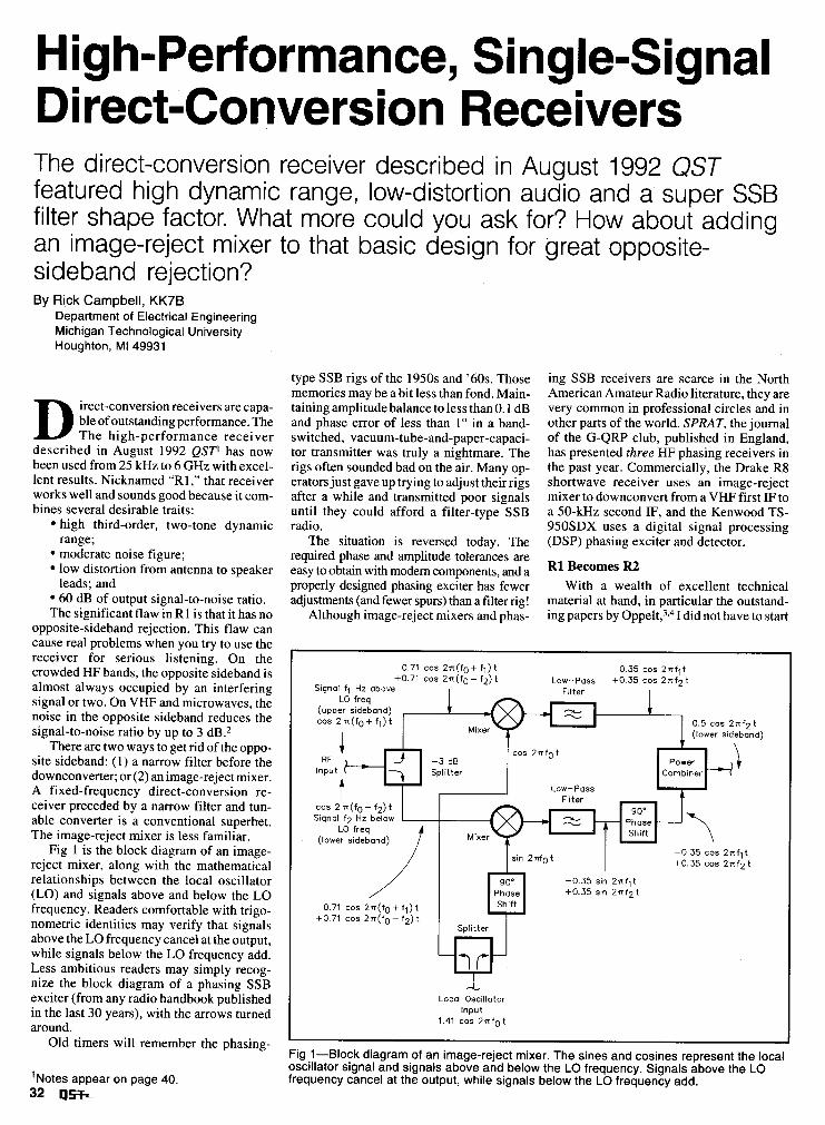
Fig 1 is the block diagram of an image- reject mixer, along with the mathematical relationships between the local oscillator (LO) and signals above and below the LO frequency. Readers comfortable with trigo- nometric identities may verify that signals above the LO frequency cancel at the output, while signals below the LO frequency add. Less ambitious readers may simply recog- nize the block diagram of a phasing SSB exciter (from any radio handbook published in the last 30 years), with the arrows turned around.
Old timers will remember the phasing-
' ~ o t e s appear on page 40. 32 USL
type SSB rigs of the 1950s and '60s. Those memories may be a bit less than fond. Main- taining amplitude balance to less than 0.1 dB and phase error of less than 1" in a band- switched, vacuum-tube-and-paper-capaci- tor transmitter was truly a nightmare. The rigs often sounded bad on the air. Many op- erators just gave up trying to adjust their rigs after a while and transmitted poor signals until they could afford a filter-type SSB radio.
The situation is reversed today. The required phase and amplitude tolerances are easy to obtain with modem components, and a properly designed phasing exciter has fewer adjustments (and fewer spurs) than a filter rig!
Although image-reject mixers and phas-
ing SSB receivers are scarce in the North American Amateur Radio literature, they are very common in professional circles and in other parts of the world. SPRAT, the journal of the G-QRP club, published in England, has presented three HF phasing receivers in the past year. Commercially, the Drake R8 shortwave receiver uses an image-reject mixer to downconvert from a VHF first IF to a 50-kHz second IF, and the Kenwood TS- 950SDX uses a digital signal processing (DSP) phasing exciter and detector.
R1 Becomes R2 With a wealth of excellent technical
material at hand, in particular the outstand- ing papers by O ~ p e l t , ~ . ~ I did not have to start
0.71 cos 2n(f0 + fl) t 0.35 cos 2nflt +0.71 cos 2n(f0 - f2) t Low-Pass +0.35 cos 2 n f 2 t
Signal f l Hz above
-0.35 cos 2nflt +0.35 cos 2 n f 2 t
+0.35 sin 2 n f 2 t
Local Oscillator Input
1.41 cos 2n f0 t
Fig 1-Block diagram of an image-reject mixer. The sines and cosines represent the local oscillator signal and signals above and below the LO frequency. Signals above the LO frequency cancel at the output, while signals below the LO frequency add.
I Channel To LO,
Band-Pass
Components inside dashed lines are included on the original R1 board.
r--------- 1 Splitter Mixer Preamp Audio
Phase- I Shift
Filter - Network Summer Input
1 I Band-Pass
Diplexer I I I I
I I I I I I
L ------- -l I L -
To LO2
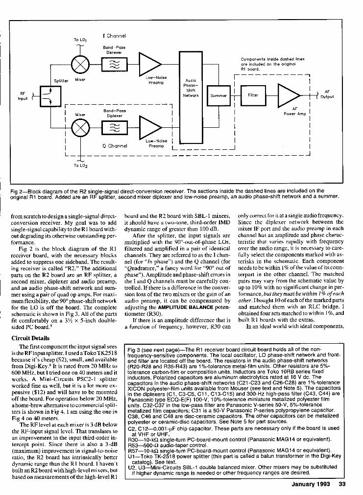
I Fig 2-Block diagram of the R2 single-signal direct-conversion receiver. The sections inside the dashed lines are included on the original R1 board. Added are an RF splitter, second mixer diplexer and low-noise preamp, an audio phase-shift network and a summer.
from scratch to design a single-signal direct- conversion receiver. My goal was to add single-signal capability to the R1 board with- out degrading its otherwise outstanding per- formance.
Fig 2 is the block diagram of the R1 receiver board, with the necessary blocks added to suppress one sideband. The result- ing receiver is called "R2." The additional parts on the R2 board are an RF splitter, a second mixer, diplexer and audio preamp, and an audio phase-shift network and sum- mer using a pair of quad op amps. For maxi- mum flexibility, the 90" phase-shift network for the LO is off the board. The complete
I schematic is shown in Fig 3. All of the parts I fit comfortably on a 3% x 5-inch double-
sided PC board.5 I ' Circuit Details
The first component the input signal sees is the RF input splitter. I used aToko TK25 18 because it's cheap ($2), small, and available from Digi-Key.6 It is rated from 20 MHz to 600 MHz, but I tried one on 40 meters and it works. A Mini-Circuits PSC2-1 splitter worked fine as well, but it is a lot more ex- pensive ($12) and will have to be mounted off the board. For operation below 20 MHz, a home-brew alternative to commercial split- ters is shown in Fig 4. I am using the one in Fig 4 on 40 meters.
The RF level at each mixer is 3 dB below the RF-input signal level. That translates to an improvement in the input third-order in- tercept point. Since there is also a 3-dB (maximum) improvement in signal-to-noise ratio, the R2 board has intrinsically better dynamic range than the R1 board. I haven't built an R2 board with high-level mixers, but based on measurements of the high-level R1
board and the R2 board with SBL-1 mixers, it should have a two-tone, third-order IMD dynamic range of greater than 100 dB.
After the splitter, the input signals are multiplied with the 90"-out-of-phase LOs, filtered and amplified in a pair of identical channels. They are referred to as the I chan- nel (for "In phase") and the Q channel (for "Quadrature," a fancy word for "90" out of phase"). Amplitude and phase-shift errors in the I and Q channels must be carefully con- trolled. If there is a difference in the conver- sion loss of the two mixers or the gain of an audio preamp, it can be compensated by adjusting the AMPLITUDE BALANCE poten- tiometer (R30).
If there is an amplitude difference that is a function of frequency, however, R30 can
only correct for it at a single audio frequency. Since the diplexer network between the mixer IF port and the audio preamp in each channel has an amplitude and phase charac- teristic that varies rapidly with frequency over the audio range, it is necessary to care- fully select the components marked with as- terisks in the schematic. Each component needs to be within 1 % of the value of its coun- terpart in the other channel. The matched pairs may vary from the schematic value by up to 10% with no significant change in per- formance, but they must be within 1 % of each other. I bought 10 of each of the marked parts and matched them with an RLC bridge. I obtained four sets matched to within 1 %, and built R1 boards with the extras.
In an ideal world with ideal components,
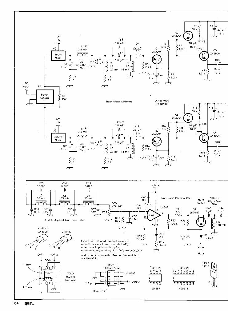
Fig 3 (see next page)-The R1 receiver board circuit board holds all of the non- frequency-sensitive components. The local oscillator, LO phase-shift network and front- end filter are located off the board. The resistors in the audio phase-shift networks (R20-R28 and R35-R43) are 1%-tolerance metal-film units. Other resistors are 5%- tolerance carbon-film or composition units. Inductors are Toko 1 ORB series fixed inductors. Polarized capacitors are aluminum electrolytics rated at 16 V dc. The capacitors in the audio phase-shift networks (C21-C23 and C26-C28) are 1%-tolerance XlCON polyester-film units available from Mouser (see text and Note 5). The capacitors in the diplexers (Cl, C3-C5, C11, C13-C15) and 300-Hz high-pass filter (C43, C44) are Panasonic type ECQ-E(F) 100-V, 10%-tolerance miniature metalized polyester film units. C32-C37 in the low-pass filter are Panasonic V-series 50-V, 5%-tolerance metalized film capacitors; C31 is a 50-V Panasonic P-series polypropylene capacitor. C38, C46 and C48 are disc-ceramic capacitors. The other capacitors can be metalized polyester or ceramic-disc capacitors. See Note 5 for part sources. C2, C12-0.001 y F chip capacitor. These parts are necessary only if the board is used
at VHF or UHF. R30-10-kR single-turn PC-board-mount control (Panasonic MAG14 or equivalent). R53-500-R audio-taper control. R57-10-kR single-turn PC-board-mount control (Panasonic MAG14 or equivalent). U1-Toko TK-2518 power splitter (this part is called a balun transformer in the Digi-Key
catalog). See text. U2, U3-Mini-Circuits SBL-1 double balanced mixer. Other mixers may be substituted
if h i~her dynamic range is needed or other frequency ranges are desired.
January 1993 33
0' LO C4 *
- SBL-1
2 7 m H l 8 m H
RF
Band-Pass Diplexers 50- Cl Audio
90' LO ~ 1 4 *
27rnH 1 8 m H
C31 C32 C33 0.0068 0.033 0.022 +12 v
I f I I I f -
L7 L8 L9 33 rnH 33 rnH 33 mH Low-Noise Preamplifier 300-Hz
)?:ceh High-Pass --4
500 C39 Filter VOLUME 0.1 LM387 R51 P7 C43 C44 I f 470 2N5457 pF
3-kHz Elliptical Low-Pass Filter R50 R52
l o o k 1 M
21'13904
Except as indicated, decimal values of
C capacitance are in microfarads ( p F ) ;
D others ore in picofarads ( p F ) ; Ground resistances are in ohms; k=1,000, M=1.000,000. to
OUT 1 OUT 2 Mute * Matched components. See caption and text. ** Heotsink
SBL-1 . TIP29.
Bottom V~ew Top V~ew Top V~ew TIP30
8 -4 LO lnput 14131211 10 9 8
TOKO TK2518
Top View RF lnput + 1 IF Output
1 2 3 4 1 2 3 4 5 6 7
LM387 NE5514 Blue R ~ n g
January 1993 35
R10 --+I2 v
1 k
Break connection here and insert sideband selection switch (see text). -
+12 v To
Fig 5
R29 R35
4.7 k 10 k C25
10 p F R30 2 - 4
I O 1
AMPLITUDE 4.7 k
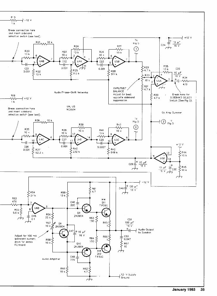
Audio Phase-Shift Networks BALANCE
R19 - w + 1 2 V
1 k
Adjust for best opposite sideband suppression
4.7 k ~ 3 3 . Break here for
SIDEBAND SELECT Switch (See Fig 5).
U4, U5 Break connection here NE5514 and insert sideband selection switch (see text).
+12 v
Adjust for 100 m A quiescent current drain for entire R2 board
Audio Amplifier 220
4 )
R60 10 k
12-v Supply - Ground
4 I
Op Amp Summer
2 bffilar turns on # 43 ferrite bead
Phasing 4 turns on 1 4 3 ferrite beod
(50 0: 25 fl auto-transformer) Top 3 turns abovs ground.
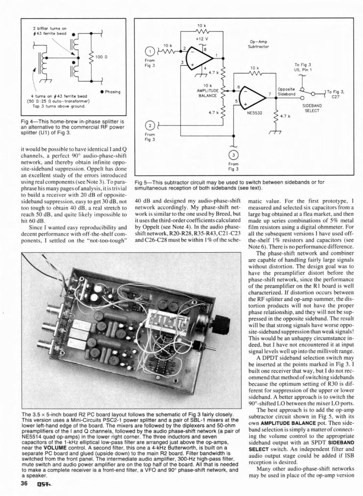
Fig 4-This home-brew in-phase splitter is an alternative to the commercial RF power splitter (Ul) of Fig 3.
it would be possible to have identical 1 and Q channels, a perfect 90" audio-phase-shift network. and thereby obtain infinite oppo- site-sideband suppression. Oppelt has done an excellent study of the errors introduced usingreal components (see Note 3). To para- phrase his many pages of analysis, it is trivial to build a receiver with 20 dB of opposite- sideband suppression. easy to get 30 dB, not too tough to obtain 40 dB, a real stretch to reach 50 dB, and quite likely impossible to hit 60 dB.
Since I wanted easy reproducibility and decent performance with off-the-shelf com- ponents, I settled on the "not-too-tough"
10 k
+12 v Op-Amp
Subtractor
SIDEBAND
From qb Fig 3 -
0 From Fig 3
Fig %This subtractor circuit may be used to switch between sidebands or for simultaneous reception of both sidebands (see text).
40 dB and designed my audio-phase-shift matic value. For the first prototype, I network accordingly. My phase-shift net- measured and selected six capacitors from a work is similar to the one used by Breed. but large bag obtained at a flea market, and then it uses the third-ordercoefficientscalculated made up series combinations of 5% metal by Oppelt (see Note 4). In the audio phase- film resistors using a digital ohmmeter. For shift network, R20-R28, R35-R43,C21 -C23 all the subsequent versions I have used off- and C26-C28 must be within I % of the sche- the-shelf 1 % resistors and capacitors (see
Note 6). There is no performance difference. The phase-shift network and combiner
are capable of handling fairly large signals without distortion. The design goal was to have the preamplifier distort before the phase-shift network, since the performance of the preamplifier on the Rl board is well characterized. If distortion occurs between the RF splitter and op-amp summer, the dis- tortion products will not have the proper phase relationship, and they will not be sup- pressed in the opposite sideband. The result will be that strong signals have worse oppo- site-sideband suppression than weak signals! This would be an unhappy circumstance in- deed, but I have not encountered it at input signal levels well up into the millivolt range.
A DPDT sideband selection switch may be inserted at the points marked in Fig 3. I built one receiver that way, but I do not rec- ommend that methodof switching sidebands because the optimum setting of R30 is dif- ferent for suppression of the upper or lower sideband. A better approach is to switch the 90"-shifted LO between the mixer LO ports.
The 3.5 x 5-inch board R2 PC board layout follows the schematic of Fig 3 fairly closely. This version uses a Mini-Circuits PSC2-1 power splitter and a pair of SBL-1 mixers at the lower left-hand edge of the board. The mixers are followed by the diplexers and 50-ohm preamplifiers of the I and Q channels, followed by the audio phase-shift network (a pair of NE5514 quad op-amps) in the lower right corner. The three inductors and seven capacitors of the 1-kHz elliptical low-pass filter are arranged just above the op-amps, near the VOLUME control. A second filter, this one a 4-kHz Butterworth, is built on a separate PC board and glued (upside down) to the main R2 board. Filter bandwidth is switched from the front panel. The intermediate audio amplifier, 300-Hz high-pass filter, mute switch and audio power amplifier are on the top half of the board. All that is needed to make a complete receiver is a front-end filter, a VFO and 90" phase-shift network, and a speaker.
The best approach is to add the op-amp subtractor circuit shown in Fig 5 , with its own AMPLITUDE BALANCE pot. Then side- band selection is simply a matter of connect- ing the volume control to the appropriate sideband output with an SPDT SIDEBAND SELECT switch. An independent filter and audio output stage could be added if ISB reception is desired.
Many other audio-phase-shift networks may be used in place of the op-amp version
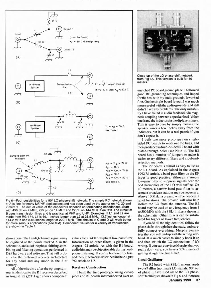
Fig &Four possibilities for a 90" LO phase-shift network. The simple RC network shown at A is fine for many MFlHF applications and has been used by the author on 40, 20 and 2 meters. The actual value of the capacitors depends on terminating impedances. Start with 450 pF on 7 MHz. 225 pF on 14 MHz and 22 pF on 144 MHz. See text. The circuit a t 6 uses transmission lines and is practical at VHF and UHF. Examples: If L1 and L2 are made from RG-174, L1 is 69.1 inches longer than L2 at 28.5 MHz; 13.7 inches longer at 144.2 MHz and 8.86 inches longer at 222.1 MHz. The circuits at C and D will work better for more serious applications (see text). Component values for a variety of frequencies are shown in Table 1.
output 1
(Used by Breed) XC = 50 fl 0 design freq
output 2
L l
n
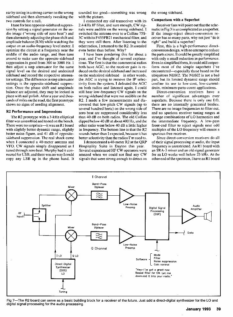
shown here. The I and Q channel signals may values for a 3-kHz elliptical low-pass filter. be digitized at the points marked X in the Information on other filters is given in the schematic, and all of the phase shifting, com- August '92 article. As with the R1 board, bining and filtering operations performed in audio hiss may beobjectionable during head- DSP hardware and software. That will prob- phone listening. If you're bothered by hiss. ably be the preferred receiver architecture add the RC networks described in the August for any band and any mode in the 21st '92 article toU6.
b
In-Phase Splitter
century. All of the circuitry after the o p a m p sum- Receiver Construction
mer is identical to the R1 receiver described I built the first prototype using cut-up in August '92 QST. Fig 3 shows component pieces of RI boards interconnected over an
A Transmission L1 = 2 longer than L2
Line 4
if RG-174. then A g 67% A
Close-up of the LO phase-shift network from Fig 6A. This version is built for 40 meters.
L2
(B)
L
In-Phase XC - XC = 50 R Splitter
See Table 1.
('3
Lumped Uament C2 L3 Mikinson
X L ~ = X L ~ - 71 fl XCl = 35 R
k 2 ' %3' 71 X L ~ = 50 fl Xc4 = Xc5 = 50 R
Sea Table 1.
unetched PC board ground plane. I followed good RF grounding techniques and hoped forthebest with my audiogrounds. It worked fine. On the single-board layout, I was much morecareful with the audiogrounds. and still didn't have any problems. The only instabil- ity I have found is audio feedback via mag- netic coupling between a speaker lead (either one!) and the inductors in the diplexer stages. This is easy to cure by simply moving the speaker wires a few inches away from the inductors, but it can be a real puzzle if you don't expect it.
I built two more prototypes on single- sided PC boards to work out the bugs. and then produced a double-sided R2 board with plated-through holes (see Note 1). The R2 board has a number of jumpers to make it easier to try different filters and sideband- selection methods.
The R2 board is almost as easy to use as the Rl board. As explained in the August 1992 R1 article, a band-pass filter on the RF input is good practice, although a simple low-pass filter to suppress signals near the odd harmonics of the LO will suffice. On 40 meters, a narrow band-pass filter to at- tenuate broadcast stations may be necessary. Above 10 MHz, a preamp will be needed in quiet locations. The preamp will also help isolate the LO from the antenna. The R2 board may be used on any frequency from 1 to SOOMHz with the SBL-I mixers shown in the schematic. Other mixers can be substi- tuted for higher or lower frequencies.
If you do all the trig identities, follow the phase shifts through the schematic, and care- fully connect everything, Murphy guaran- tees that you will end up with the wrong side- band. It is much easier to simply hook it up and then switch the LO connections if it's wrong. If you can convince Murphy that you really don't care, you have a 50% chance of getting it right the first time!
Local Oscillator The R2 board with SBL-I mixers needs
two +7 dBm (nominal) LO signals, 90" out of phase. I have used all of the LO phase- shift techniques shown in Fig 6, and there are
January 1993 37
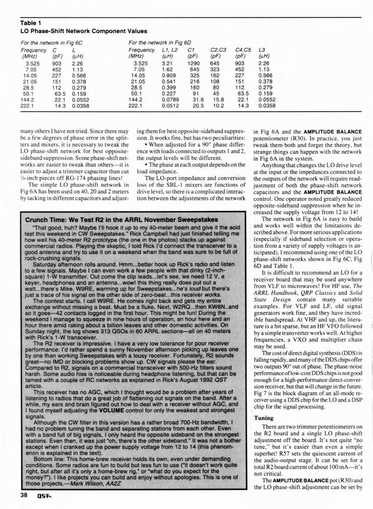
Table 1 LO Phase-Shift Network Component Values
For the network in Fig 6C Frequency C L (MHz) (PF) (pH) 3.525 903 2.26 7.05 452 1.13 14.05 227 0.566 21.05 151 0.378 28.5 112 0.279 50.1 63.5 0.159 144.2 22.1 0.0552 222.1 14.3 0.0358
For the network in Fig 6D Frequency L1, L2 C1 (MHz) (pH) (PF) 3.525 3.21 1290 7.05 1.62 645 14.05 0.809 325 21.05 0.541 216 28.5 0.399 160 50.1 0.227 91 144.2 0.0789 31.6 222.1 0.0512 20.5
many others I have not tried. Since there may ing them for best opposite-sideband suppres- in Fig 6A and the AMPLITUDE BALANCE sion. It works fine, but has two peculiarities: potentiometer (R30). In practice, you just
When adjusted for a 90' phase differ- tweak them both and forget the theory, but ence with loads connected to outputs 1 and 2, strange things can happen with the network the output levels will be different. in Fig 6A in the system.
The phase at each output depends on the Anything that changes the LO drive level load impedance. at the input or the impedances connected to
The LO-port impedance and conversion the outputs of the network will require read- loss of the SBL-I mixers are functions of justment of both the phase-shift network drive level, so there i s acomplicated interac- capacitors and the AMPLITUDE BALANCE tion between the adjustments of the network control. One operator noted greatly reduced
opposite-sideband suppression when he in- creased the supply voltage from 12 to 14!
The network in Fig 6A is easy to build and works well within the limitations de- scribed above. For more serious applications
I (especially i f sideband selection or opera- tion from a variety of supply voltages is an- ticipated), I recommend using one of the LO phase-shift networks shown in Fig 6C, Fig 6D and Table 1.
I t i s difficult to recommend an LO for a
be a few degrees of phase error in the split- ters and mixers, i t i s necessary to tweak the LO phase-shift network for best opposite- sideband suppression. Some phase-shift net- works are easier to tweak than others-it i s easier to adjust a trimmer capacitor than cut %-inch pieces off RG-174 phasing lines!
The simple LO phase-shift network in Fig 6A has been used on 40.20 and 2 meters by tacking in different capacitors and adjust-
r I ! in the ARRL November $
ood, huh? Maybe I'll hook it up to my 40-meter beam and give it the acid test this weekend in CW Sweepstakes." Rick Campbell had just finished telling me how well his 40-meter R2 prototype (the one in the photos) stacks up against commercial radios. Playing the skeptic, I told Rick I'd connect the transceiver to a good antenna and try to use it on a weekend when the band was sure to be full of rock-crushing signal
Saturday aftemoc n to a few signals. Ma square) 1 -W transm keyer, headphones arlu arr arrtertrta...wuw! IIIIS ~rrlrty really uuas (JUL u wa tt... there's Mike, WSRE, warming up for Sweepstakes ... he's loud b~ just a trace of his signal on the other side of zero-beat ... this receiver I
The contest starts. I call W9RE. He comes right back and gets my exchange without missing a beat. Must be a fluke. Next, W2RQ ... then KweN..ana so it g o e s 4 2 contacts logged in the first hour. This might be fun! During the weekend I manage to squeeze in nine hours of operation, an hour here and an hour there amid raking about a billion leaves and other domestic activities. On Sunday night, the log shows 313 QSOs in 60 ARRL sections-all on 40 meters with Rick's 1-W transceiver.
The R2 receiver is impress performance: I'd rather spend ne by one than working Sweepsta~es witn a lousy receiver. tonunarely, HZ sounas great--no IMD or blocking problems show up. CW signals please the Compared to R2, signals on a commercial transceiver with 500-Hz filt I
harsh. Some audio hiss is noticeable during headphone listening, but )e tamed with a couple of RC networks as explained in Rick's August 19 article.
This re ; no AGC, which I thought would be a problem after years of listening tc bat do a great job of flattening out signals on the band. After a while, my ears ana main figured out how to deal with a receiver without AGC, and I found myself adjusting the VOLUME control for only the weakest and strongest signals.
Althou! her broad I had no prc tations fro with a ban0 ruil or oig slgnais, I only nearo me opposite sideoano on rne srronoest stations. Even then, it was just "oh, there's the other sideband." It wa! ther except when I cranked up the pply volta! ! to 14 (thi enon is explained in the text).
Bottom line: This home-brew receiver holds its own, even under demanding conditions. Some radios are fun to build but less 1 ite right, but after all it's only a home-brew money?"). I like projects you can build s of those projects.-Mark Wilson, AA2Z
Crunch 1 "That g
! Test R2
S. on rolls arl ybe l can itter. Out c --A -- --
ound. Hml even work :ome the ( . - - - . . .
m...better ; a few pec :lip leads.. ..-.I .L:- IL:
hook up F 3ple with t ..let's see, -- ---,I.. .
lick's radic hat dinky we need
.I^^ ̂ -..a ^
I and liste (2-inch- 12V,a . .. ̂ receiver board that may be used anywhere
from VLF to microwaves! For HF use. The ARRL Handbook. QRP Classics and Solid State Design contain many suitable ' examples. For VLF and LF, old signal generators work fine, and they have incred- ible bandspread. At VHF and up, the litera- ture is a bit sparse, but an HF VFO followed I by a simple transverter works well. At higher frequencies, a VXO and multiplier chain may be used.
The cost of direct digital synthesis (DDS) i s ~
fallingrapidly, and many of the DDS chipsoffer ' two outputs 90" out of phase. The phase-noise 1
IUl a ut there's works. entire .--.-.. .
,ive. I havt a sunny P ...
3 a very lo Jovember
w toleranc afternoon . -
:e for pool picking ul . . .
* receiver p leaves a -- ear. ers sound that can t 192 QST
performanceof low-cost DDS chips i s not good I enough for a high-performance direct-conver-
, sion receiver, but that will change in the future. Fig 7 is the block diagram of an all-mode re- ceiver using a DDS chip for the LO and a DSP , chip for the signal processing.
I
ceiver has s radios tl- . .
is version nd and sel . - - n . L - .
has a rat1 parating s . -3 .L -
700-HZ bi m each ot -L--A - - A
indwidth. her. Even .L_ -A ----
Tuning I
3h the CW sblem tuni 3 c 0. - * L
filter in tP ing the ba~ .- 0 .
There are two trimmer potentiometers on the R2 board and a single LO phase-shift
I adjustment off the board. It's not quite "no tune," but it's easier than even a simple superhet! R57 sets the quiescent current of the audio-output stage. It can be set for a total R2 board current of about 100 mA-it's not critical.
The AMPLITUDE BALANCE pot (R30) and the LO phase-shift adjustment can be set by
s not a bi;i s phenom ge from 1;
'un to use hat do yo1 without ap
("it doesn 1 expect fc ~ologies. T
't work qui )r the 'his is one
rig," or "w ind enjoy
ear by tuning in a strong carrier on the wrong sideband and then alternately tweaking the two controls for a null.
I tune for best opposite-sideband suppres- sion by setting a signal generator on the au- dio image ("wrong side of zero beat") and then alternately adjusting the phase shift and amplitude balance (R30) while watching the output on an audio-frequency level meter. I optimize the circuit at a frequency near the middle of the audio range, and then tune around to make sure the opposite-sideband suppression is good from 300 to 3000 Hz. I then adjust a step attenuator for the same signal level on the desired and undesired sideband and record the respective attenua- tor settings. The difference in step attenuator settings is the opposite-sideband suppres- sion. Once the phase shift and amplitude balance are adjusted, they may be locked in place with nail polish. After a year and thou- sands of miles on the road, the first prototype shows no signs of needing alignment.
R2 Performance and Impressions The R2 prototype with a 3-kHz elliptical
filter was assembled and tested on the bench. There were no surprises-it was an R1 board with slightly better dynamic range, slightly better noise figure, and 41 dB of opposite- sideband suppression. The real shock came when I connected a 40-meter antenna and VFO. CW signals simply disappeared as I tuned through zero beat. Murphy had it con- nected for USB, and there was no way I could copy any LSB up in the phone band. It
sounded too good-something was wrong with the picture.
I connected my old transceiver with its 2.4-kHz IF filter, and sure enough, CW sig- nals were audible on the wrong sideband. I switched the antenna over to a Collins 75s- 3C with its F455FB21 mechanical filter, and they were still there. After listening to the other radios, I returned to the R2. It sounded even better than before. Why?
I have been pondering this for about a year, and I've thought of several explana- tions. The first is that the commercial radios both have AGC, so the receiver gain is re- duced on the desired sideband and increased on the undesired sideband-in other words, the AGC is trying to remove the IF selec- tivity from the system. I defeated the AGC on both radios and listened again. I could still hear low-frequency CW signals on the wrong sideband that were not audible on the R2. I made a few measurements and dis- covered that low-pitch CW signals (up to several hundred hertz) on the wrong side of zero beat are suppressed considerably less than 40 dB on both radios. The old Collins dipped below 40 dB at about 400 Hz, and the other radio went below 40 dB a little higher in frequency. The bottom line is that the R2 sounds better than I expected, because it has better selectivity than the radios I'm used to.
I demonstrated a 40-meter R2 at the QRP Hospitality Suite in Dayton this year. Several experienced HF CW operators were amazed when we could not find any CW signals that were strong enough to detect on
the wrong sideband.
Comparison with a Superhet Receiver fans will point out that the sche-
matic in Fig 3 is as complicated as a superhet. If the image-reject direct-conversion re- ceiver has so many parts, why not just "do it right" and build a superhet?
First, this is a high-performance direct- conversion design, with no attempt to reduce the parts count. It could be greatly simplified with only a small reduction in performance. Even in simplified form, it could still outper- form most of the simple superhets I've encountered+specially those based on the ubiquitous NE602. The NE602 is not a bad par( but its limited dynamic range should confine its use to low-cost, low-current- drain, minimum-parts-count applications.
Direct-conversion receivers have a number of significant advantages over superhets. Because there is only one LO, there are no internally generated birdies. There are no image frequencies to filter out, and no spurious receiver tuning ranges at strange combinations of LO harmonics and the intermediate frequency. A low-pass front-end filter to reject signals near odd multiples of the LO frequency will ensure a spurious-free receiver.
Since direct-conversion receivers do all of their signal processing at audio, the input frequency is unrestricted. An R l board with an SRA-3 mixer and an old signal generator for an LO works well below 25 kHz. At the other end of the spectrum, I have an R l board
I Channel
Band-Pass Mixer Diplexer -
c.u - Splitter
Preamp Audio Digital Signal Processing
RF Input
Bond-Pass
Data
Q Channel
H e y l ' v e got a great new Bessel filter for CW. Let m e download it into your radio."
Tuning
Fig 7-The R2 board can serve a s a basic building block for a receiver of the future. Just add a direct-digital synthesizer for the LO and digital signal processing for the audio processing.
January 1993 39
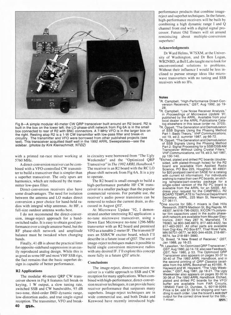
Fig &A simple modular 40-meter CW QRP transceiver built around an R2 board. R2 is built in the box on the lower left; the LO phase-shift network from Fig 6A is in the small box connected to rear of R2 with BNC connectors. A 7-MHz VFO is in the larger box on the right. Resting atop R2 is a 1-W CW transmitter with low-pass filter and break-in circuitry. The transmitter and VFO were borrowed from other published projects (see text). This transceiver acquitted itself well in the 1992 ARRL Sweepstakes-see the sidebar. (photos by Kirk Kleinschmidt, NT0Z)
with a printed rat-race mixer working at 5760 MHz.
A direct-conversion receiver can be com- bined with a VFO-controlled C W transmit- ter to bui ld a transceiver that is simpler than a superhet transceiver. The only spurs are harmonics, which are reduced by the trans- mitter low-pass filter.
Direct-conversion receivers also have some disadvantages. The need for isolation between the antenna and L O makes direct conversion a poor choice for hand-held ra- dios with integral whip antennas. A t HF, a full-size outdoor antenna works best. I do not recommend the direct-conver-
sion, image-reject approach for a band- switched radio. I t is easy to obtain good per- formance over a single amateur band, but the R F phase-shift network and amplitude balance must be tweaked when changing bands.
Finally, 41 dB is about the practical l imi t for opposite-sideband suppression i n an eas- i l y reproduced analog design. While this is as good as scme H F and most V H F SSB rigs, the fact remains that the basic superhet de- sign is capable o f better performance.
R2 Applications The modular 40-meter QRP C W trans-
ceiver shown i n F ig 8 features fu l l break-in keying, 1 W output, a slow tuning rate, switched SSB and C W bandwidths, 93 dB two-tone, third-order IMD dynamic range, low-distortion audio, and true single-signal reception. The transmitter, VFO and break-
40 u s
i n circuitry were borrowed from "The Ugly Weekender" and the "Optimized QRP Transceiver" i n The 1992ARRL Handbook.'' The receiver is an R2 board with the RC L O phase-shift network from F ig 6A. I t is a joy to operate.
The R2 board is small enough to bui ld a high-performance portable H F C W trans- ceiver i n a smaller package than the popular commercial versions. For portable use, the receiver's audio power transistors can be removed to reduce the current drain, as dis- cussed i n August QST.
A t Microwave Update '92, I demon- strated another inteiesting R 2 application: a no-tune microwave transceiver, using a Down East Microwave no-tune 1296-MHz transverter with an R2 board and premixed VFO as a tunable 2-meter IF. The transmit I F uses an SSBICW exciter board, which I'll describe i n a future issue o f QST:The use o f image-reject techniques makes i t possible to bui ld single conversion microwave radios with any desired IF. I'll explore this concept more ful ly i n a future QST article.
Conclusions The image-reject, direct-conversion re-
ceiver is a viable approach to SSB and C W reception for many applications. When com- bined with high-performance, direct-conver- sion receiver techniques, i t can provide basic receiver performance that surpasses many superhets. Image-reject techniques are i n wide commercial use, and both Drake and Kenwood have recently introduced high-
performance products that combine image- reject and superhet techniques. I n the future, high-performance receivers w i l l be built by combining a high dynamic range I and Q channel front end with a digital signal pro- cessor. Future O ld Timers w i l l sit around reminiscing about multiple-conversion superhets!
Acknowledgments Dr Ward Helms, W7SXM. at the Univer-
sity o f Washington, and Dr Ben Logan, WB2NBD, at Bel l Labs taught me tolook for unconventional solutions to problems. Without their influence I would be less in- clined to pursue strange ideas l ike micro- wave transverters with no tuning and SSB receivers with no IFs.
Notes ' R. Campbell. "High-Performance Direct-Con-
version Receivers," QST, Aug 1992. pp 19- 28.
2 ~ k a m p b e l l . "Low N o i ~ e Receiver Analysis," in Proceedings of M~crowave Update '91. published by the ARRL. Available from your local dealer or the ARRL Publications Cata- log elsewhere in this Issue (order no. 3703).
3 ~ . Oppelt. "The Generation and Demodulation of SSB Signals Using the Phasing Method Part 1 : Basic Theory," VHFCommunications, vol 19. ed 2. summer 1987. pp 66-72.
4 ~ . Oppelt. "The Generation and Demodulation of SSB Signals Using the Phasing Method Part 2: Signal Processing for a SSBIDSBIAM Transceiver Without Using Crystal Filters." VHF Communications. vol 19. ed 3. fall 1987. pp 130-140.
5~tched, plated and drilled PC boards (double- sided, with plated-through holes) for the R2 board are available from Applied Radio Science. PO Box 225, Houghton, MI 49931 for $20 postpaid (send an SASE for a catalog with current kit information). For individuals wishing to maketheirown PC boards, an etch- ing templatelpart-overlay package for a single-sided version of the R2 PC board is available from the ARRL for an SASE. Ad- dress our request for the CAMPBELL R2 B o A ~ i ~ ~ ~ ~ L ~ ~ ~ t o ~ e c h n i c a l ~epartment Secretary, ARRL, 225 Main St, Newington, CT 06111. - -~
60ne source for SBL-1 mixers is Oak Hills Research. 20879 Madison St. Big Rapids. MI 49307, tel616-796-0920). XICON 1% oolves- - r - 2 - -
ter film capacitors used in the-audio phase- shift network are available from Mouser Elec- tronics, 2401 Hwy 287 N, Mansfield, TX 76063, tel 800-346-6873, 817-483-4422, fax 817-483-0931. All other parts are available from Digi-Key, PO Box 677, Thief River Falls, MN 56701 -0677, tel800-344-4539.218-681- 6674. fax 21 8-681 -3880. . - -
' ~ - ~ r e e d , "A New Breed of Receiver," QST. Jan 1988. pp 16-23.
'R. ~ewallen; ' ~ n Optimized QRP Transceiver," QST, Aug 1980, pp 14-1 9; also see Feedback, QST, Nov 1980. p 53. The Optimized ORP Transceiver also appears on pages 30-37 to 30-40 of The 1993 ARRL Handbook, and in the second printing of ORP Classics (avail- able from the ARRL Bookshelf as #3169). R. Hayward and W. Hayward, "The 'Ugly Week- ender.'" QST, Aug 1981, pp 18-21. The Ugly Weekender also appears on pages 30-33 to 30-36 of The 1993 ARRL Handbook. Etched, plated and drilled PC boards for the VFOI buffer are available from FAR Circuits, 18N640 Field Ct. Dundee, IL 601 18-9269. Pr~ce is $4; add $1.50 for shipping and han- dling to each order. Use the board's AUX OUT output for the correct drive level for the SBL- 1 mixer. 'P--