Embed Size (px)
Citation preview
1
Network Layer 4-1
Distance Vector Algorithm
Bellman-Ford Equation (dynamic programming)Definedx(y) := cost of least-cost path from x to y
Then
dx(y) = min {c(x,v) + dv(y) }
where min is taken over all neighbors v of x
v
Network Layer 4-2
Bellman-Ford example
u
yx
wv
z2
21
3
1
1
2
53
5Clearly, dv(z) = 5, dx(z) = 3, dw(z) = 3
du(z) = min { c(u,v) + dv(z),c(u,x) + dx(z),c(u,w) + dw(z) }
= min {2 + 5,1 + 3,5 + 3} = 4
Node that achieves minimum is nexthop in shortest path ➜ forwarding table
B-F equation says:
2
Network Layer 4-3
Distance Vector Algorithm
Dx(y) = estimate of least cost from x to yNode x knows cost to each neighbor v: c(x,v)Node x maintains distance vector Dx = [Dx(y): y є N ]Node x also maintains its neighbors’ distance vectors
For each neighbor v, x maintains Dv = [Dv(y): y є N ]
Network Layer 4-4
Distance vector algorithm (4)
Basic idea:Each node periodically sends its own distance vector estimate to neighborsWhen a node x receives new DV estimate from neighbor, it updates its own DV using B-F equation:
Dx(y) ← minv{c(x,v) + Dv(y)} for each node y ∊ N
Under minor, natural conditions, the estimate Dx(y) converge to the actual least cost dx(y)
3
Network Layer 4-5
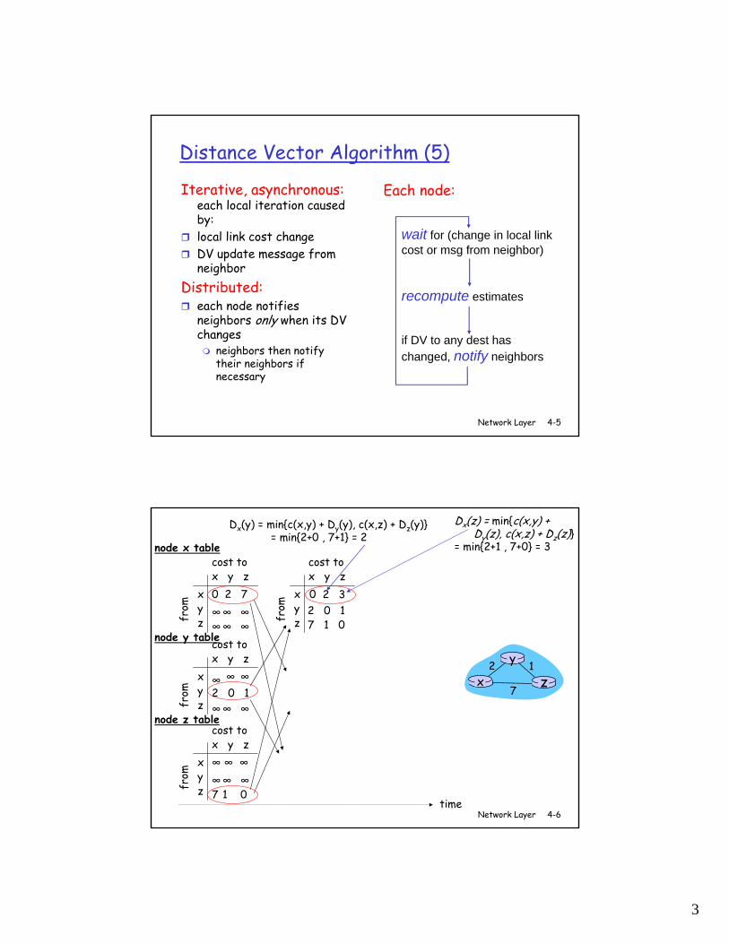
Distance Vector Algorithm (5)
Iterative, asynchronous: each local iteration caused by: local link cost change DV update message from neighbor
Distributed:each node notifies neighbors only when its DV changes
neighbors then notify their neighbors if necessary
wait for (change in local link cost or msg from neighbor)
recompute estimates
if DV to any dest has changed, notify neighbors
Each node:
Network Layer 4-6
x y zxyz
0 2 7∞∞ ∞∞∞ ∞
from
cost to
from
from
x y zxyz
0
from
cost to
x y zxyz
∞ ∞
∞∞ ∞
cost to
x y zxyz
∞∞ ∞7 1 0
cost to
∞2 0 1
∞ ∞ ∞
2 0 17 1 0
time
x z12
7
y
node x table
node y table
node z table
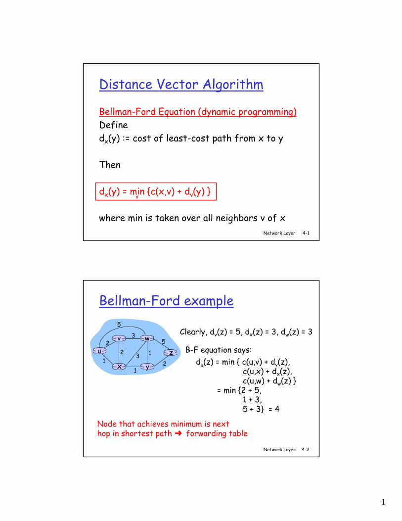
Dx(y) = min{c(x,y) + Dy(y), c(x,z) + Dz(y)} = min{2+0 , 7+1} = 2
Dx(z) = min{c(x,y) + Dy(z), c(x,z) + Dz(z)}
= min{2+1 , 7+0} = 3
32
4
Network Layer 4-7
x y zxyz
0 2 7∞∞ ∞∞∞ ∞
from
cost tofr
omfr
omx y z
xyz
0 2 3
from
cost tox y z
xyz
0 2 3
from
cost to
x y zxyz
∞ ∞
∞∞ ∞
cost tox y z
xyz
0 2 7fr
om
cost tox y z
xyz
0 2 3
from
cost to
x y zxyz
0 2 3fr
om
cost tox y z
xyz
0 2 7
from
cost tox y z
xyz
∞∞ ∞7 1 0
cost to
∞2 0 1
∞ ∞ ∞
2 0 17 1 0
2 0 17 1 0
2 0 13 1 0
2 0 13 1 0
2 0 1
3 1 02 0 1
3 1 0
time
x z12
7
y
node x table
node y table
node z table
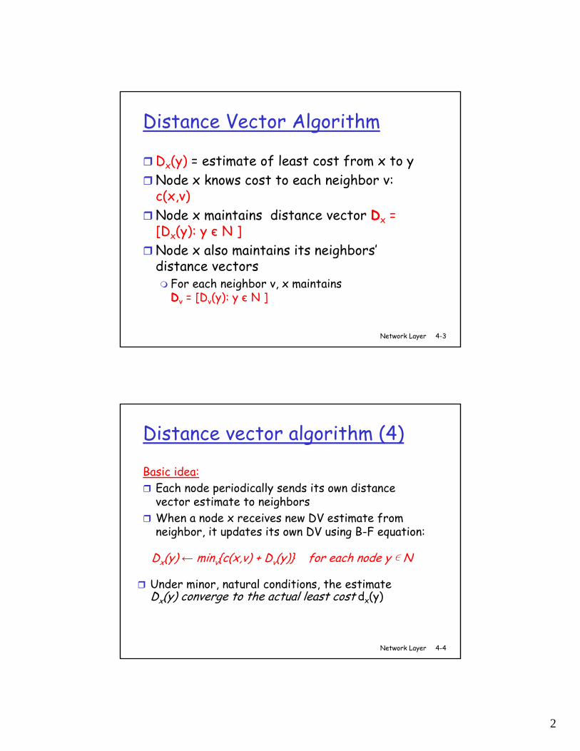
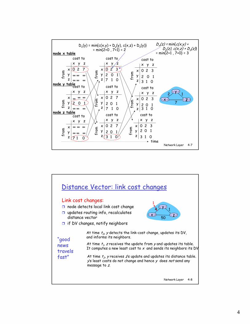
Dx(y) = min{c(x,y) + Dy(y), c(x,z) + Dz(y)} = min{2+0 , 7+1} = 2
Dx(z) = min{c(x,y) + Dy(z), c(x,z) + Dz(z)}
= min{2+1 , 7+0} = 3
Network Layer 4-8
Distance Vector: link cost changes
Link cost changes:node detects local link cost change updates routing info, recalculates distance vectorif DV changes, notify neighbors
“goodnews travelsfast”
x z14
50
y1
At time t0, y detects the link-cost change, updates its DV, and informs its neighbors.
At time t1, z receives the update from y and updates its table. It computes a new least cost to x and sends its neighbors its DV.
At time t2, y receives z’s update and updates its distance table. y’s least costs do not change and hence y does not send any message to z.
5
Network Layer 4-9
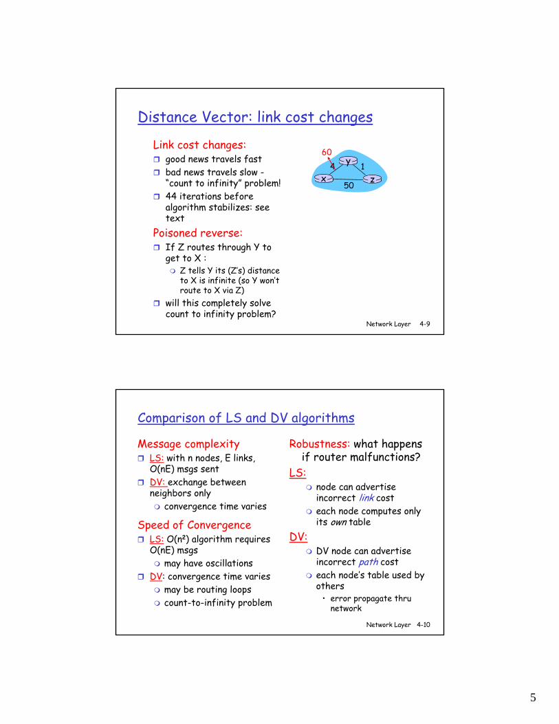
Distance Vector: link cost changes
Link cost changes:good news travels fast bad news travels slow -“count to infinity” problem!44 iterations before algorithm stabilizes: see text
Poisoned reverse:If Z routes through Y to get to X :
Z tells Y its (Z’s) distance to X is infinite (so Y won’t route to X via Z)
will this completely solve count to infinity problem?
x z14
50
y60
Network Layer 4-10
Comparison of LS and DV algorithms
Message complexityLS: with n nodes, E links, O(nE) msgs sent DV: exchange between neighbors only
convergence time varies
Speed of ConvergenceLS: O(n2) algorithm requires O(nE) msgs
may have oscillationsDV: convergence time varies
may be routing loopscount-to-infinity problem
Robustness: what happens if router malfunctions?
LS:node can advertise incorrect link costeach node computes only its own table
DV:DV node can advertise incorrect path costeach node’s table used by others
• error propagate thru network
6
Network Layer 4-11
Chapter 4: Network Layer
4. 1 Introduction4.2 Virtual circuit and datagram networks4.3 What’s inside a router4.4 IP: Internet Protocol
Datagram formatIPv4 addressingICMPIPv6
4.5 Routing algorithmsLink stateDistance VectorHierarchical routing
4.6 Routing in the Internet
RIPOSPFBGP
4.7 Broadcast and multicast routing
Network Layer 4-12
Hierarchical Routing
scale: with 200 million destinations:can’t store all dest’s in routing tables!routing table exchange would swamp links!
administrative autonomyinternet = network of networkseach network admin may want to control routing in its own network
Our routing study thus far - idealization all routers identicalnetwork “flat”
… not true in practice
7
Network Layer 4-13
Hierarchical Routing
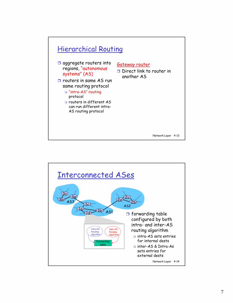
aggregate routers into regions, “autonomous systems” (AS)routers in same AS run same routing protocol
“intra-AS” routingprotocolrouters in different AS can run different intra-AS routing protocol
Gateway routerDirect link to router in another AS
Network Layer 4-14
3b
1d
3a
1c2aAS3
AS1AS2
1a
2c2b
1b
Intra-ASRouting algorithm
Inter-ASRouting algorithm
Forwardingtable
3c
Interconnected ASes
forwarding table configured by both intra- and inter-AS routing algorithm
intra-AS sets entries for internal destsinter-AS & Intra-As sets entries for external dests
8
Network Layer 4-15
3b
1d
3a
1c2aAS3
AS1AS2
1a
2c2b
1b
3c
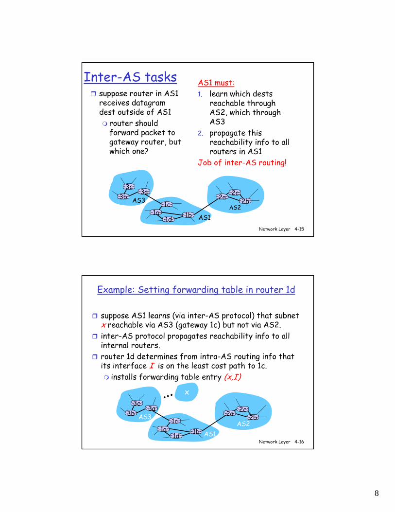
Inter-AS taskssuppose router in AS1 receives datagram dest outside of AS1
router should forward packet to gateway router, but which one?
AS1 must:1. learn which dests
reachable through AS2, which through AS3
2. propagate this reachability info to all routers in AS1
Job of inter-AS routing!
Network Layer 4-16
Example: Setting forwarding table in router 1d
suppose AS1 learns (via inter-AS protocol) that subnet x reachable via AS3 (gateway 1c) but not via AS2.inter-AS protocol propagates reachability info to all internal routers.router 1d determines from intra-AS routing info that its interface I is on the least cost path to 1c.
installs forwarding table entry (x,I)
3b
1d
3a
1c2aAS3
AS1AS2
1a
2c2b
1b
3cx…
9
Network Layer 4-17
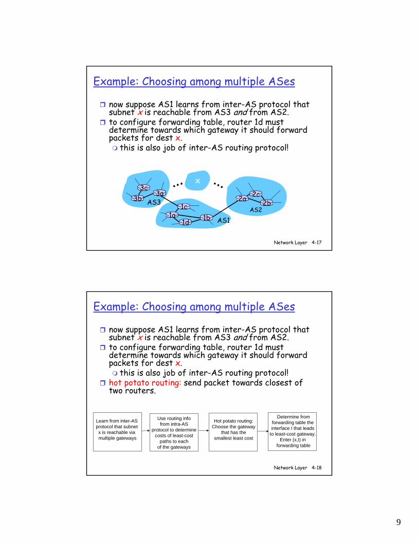
Example: Choosing among multiple ASes
now suppose AS1 learns from inter-AS protocol that subnet x is reachable from AS3 and from AS2.to configure forwarding table, router 1d must determine towards which gateway it should forward packets for dest x.
this is also job of inter-AS routing protocol!
3b
1d
3a
1c2aAS3
AS1AS2
1a
2c2b
1b
3cx… …
Network Layer 4-18
Learn from inter-AS protocol that subnet x is reachable via multiple gateways
Use routing infofrom intra-AS
protocol to determinecosts of least-cost
paths to eachof the gateways
Hot potato routing:Choose the gateway
that has the smallest least cost
Determine fromforwarding table the interface I that leads
to least-cost gateway. Enter (x,I) in
forwarding table
Example: Choosing among multiple ASes
now suppose AS1 learns from inter-AS protocol that subnet x is reachable from AS3 and from AS2.to configure forwarding table, router 1d must determine towards which gateway it should forward packets for dest x.
this is also job of inter-AS routing protocol!hot potato routing: send packet towards closest of two routers.
10
Network Layer 4-19
Chapter 4: Network Layer
4. 1 Introduction4.2 Virtual circuit and datagram networks4.3 What’s inside a router4.4 IP: Internet Protocol
Datagram formatIPv4 addressingICMPIPv6
4.5 Routing algorithmsLink stateDistance VectorHierarchical routing
4.6 Routing in the Internet
RIPOSPFBGP
4.7 Broadcast and multicast routing
Network Layer 4-20
Intra-AS Routing
also known as Interior Gateway Protocols (IGP)most common Intra-AS routing protocols:
RIP: Routing Information Protocol
OSPF: Open Shortest Path First
IGRP: Interior Gateway Routing Protocol (Cisco proprietary)
11
Network Layer 4-21
Chapter 4: Network Layer
4. 1 Introduction4.2 Virtual circuit and datagram networks4.3 What’s inside a router4.4 IP: Internet Protocol
Datagram formatIPv4 addressingICMPIPv6
4.5 Routing algorithmsLink stateDistance VectorHierarchical routing
4.6 Routing in the Internet
RIPOSPFBGP
4.7 Broadcast and multicast routing
Network Layer 4-22
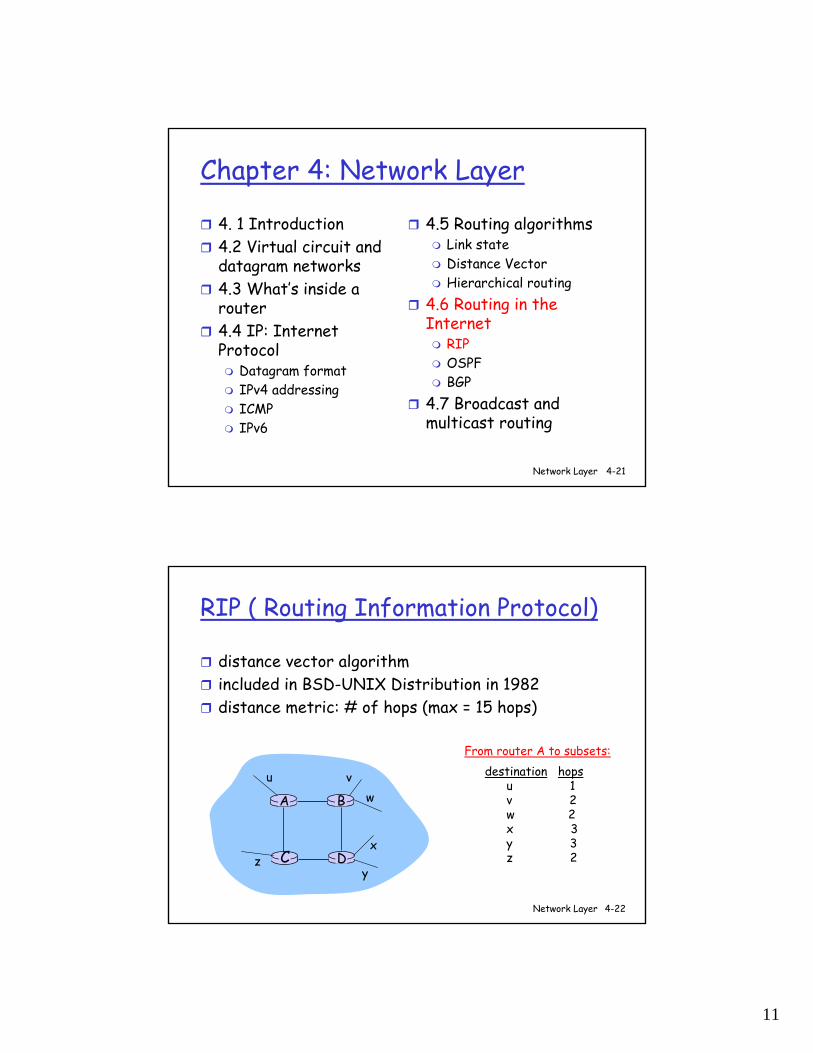
RIP ( Routing Information Protocol)
distance vector algorithmincluded in BSD-UNIX Distribution in 1982distance metric: # of hops (max = 15 hops)
DC
BA
u vw
x
yz
destination hopsu 1v 2w 2x 3y 3z 2
From router A to subsets:
12
Network Layer 4-23
RIP advertisements
distance vectors: exchanged among neighbors every 30 sec via Response Message (also called advertisement)each advertisement: list of up to 25 destination nets within AS
Network Layer 4-24
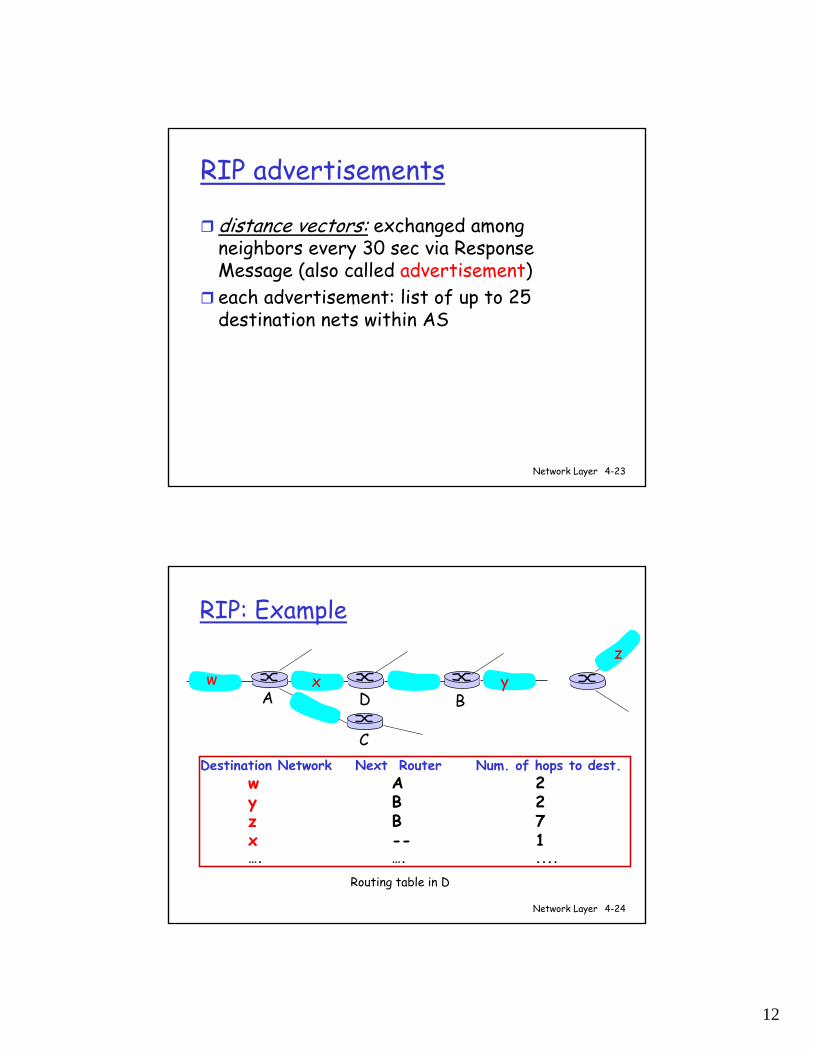
RIP: Example
Destination Network Next Router Num. of hops to dest.w A 2y B 2z B 7x -- 1…. …. ....
w x y
z
A
C
D B
Routing table in D
13
Network Layer 4-25
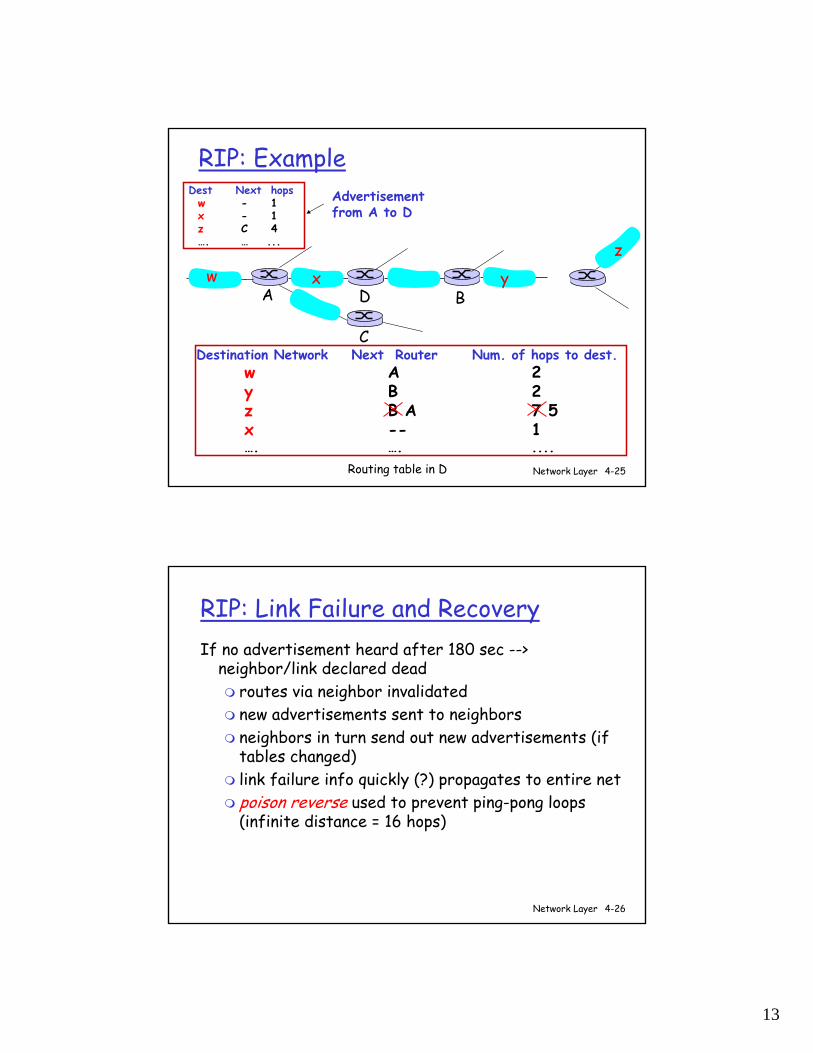
RIP: Example
Destination Network Next Router Num. of hops to dest.w A 2y B 2z B A 7 5x -- 1…. …. ....
Routing table in D
w x y
z
A
C
D B
Dest Next hopsw - 1x - 1z C 4…. … ...
Advertisementfrom A to D
Network Layer 4-26
RIP: Link Failure and RecoveryIf no advertisement heard after 180 sec -->
neighbor/link declared deadroutes via neighbor invalidatednew advertisements sent to neighborsneighbors in turn send out new advertisements (if tables changed)link failure info quickly (?) propagates to entire netpoison reverse used to prevent ping-pong loops (infinite distance = 16 hops)
14
Network Layer 4-27
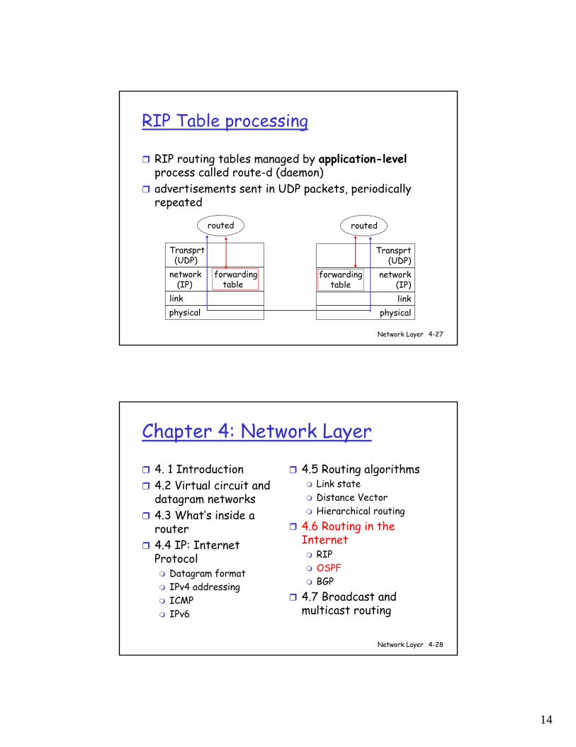
RIP Table processing
RIP routing tables managed by application-levelprocess called route-d (daemon)advertisements sent in UDP packets, periodically repeated
physicallink
network forwarding(IP) table
Transprt(UDP)
routed
physicallink
network(IP)
Transprt(UDP)
routed
forwardingtable
Network Layer 4-28
Chapter 4: Network Layer
4. 1 Introduction4.2 Virtual circuit and datagram networks4.3 What’s inside a router4.4 IP: Internet Protocol
Datagram formatIPv4 addressingICMPIPv6
4.5 Routing algorithmsLink stateDistance VectorHierarchical routing
4.6 Routing in the Internet
RIPOSPFBGP
4.7 Broadcast and multicast routing
15
Network Layer 4-29
OSPF (Open Shortest Path First)
“open”: publicly availableuses Link State algorithm
LS packet disseminationtopology map at each noderoute computation using Dijkstra’s algorithm
OSPF advertisement carries one entry per neighbor routeradvertisements disseminated to entire AS (via flooding)
carried in OSPF messages directly over IP (rather than TCP or UDP
Network Layer 4-30
OSPF “advanced” features (not in RIP)
security: all OSPF messages authenticated (to prevent malicious intrusion) multiple same-cost paths allowed (only one path in RIP)For each link, multiple cost metrics for different TOS (e.g., satellite link cost set “low” for best effort; high for real time)integrated uni- and multicast support:
Multicast OSPF (MOSPF) uses same topology data base as OSPF
hierarchical OSPF in large domains.
16
Network Layer 4-31
Chapter 4: Network Layer
4. 1 Introduction4.2 Virtual circuit and datagram networks4.3 What’s inside a router4.4 IP: Internet Protocol
Datagram formatIPv4 addressingICMPIPv6
4.5 Routing algorithmsLink stateDistance VectorHierarchical routing
4.6 Routing in the Internet
RIPOSPFBGP
4.7 Broadcast and multicast routing
Network Layer 4-32
Internet inter-AS routing: BGP
BGP (Border Gateway Protocol): the de facto standardBGP provides each AS a means to:1. Obtain subnet reachability information from
neighboring ASs.2. Propagate reachability information to all AS-
internal routers.3. Determine “good” routes to subnets based on
reachability information and policy.allows subnet to advertise its existence to rest of Internet: “I am here”
17
Network Layer 4-33
BGP basicspairs of routers (BGP peers) exchange routing info over semi-permanent TCP connections: BGP sessions
BGP sessions need not correspond to physical links.
when AS2 advertises prefix to AS1:AS2 promises it will forward any addresses datagrams towards that prefix.AS2 can aggregate prefixes in its advertisement
3b
1d
3a
1c2aAS3
AS1
AS21a
2c
2b
1b
3ceBGP session
iBGP session
Network Layer 4-34
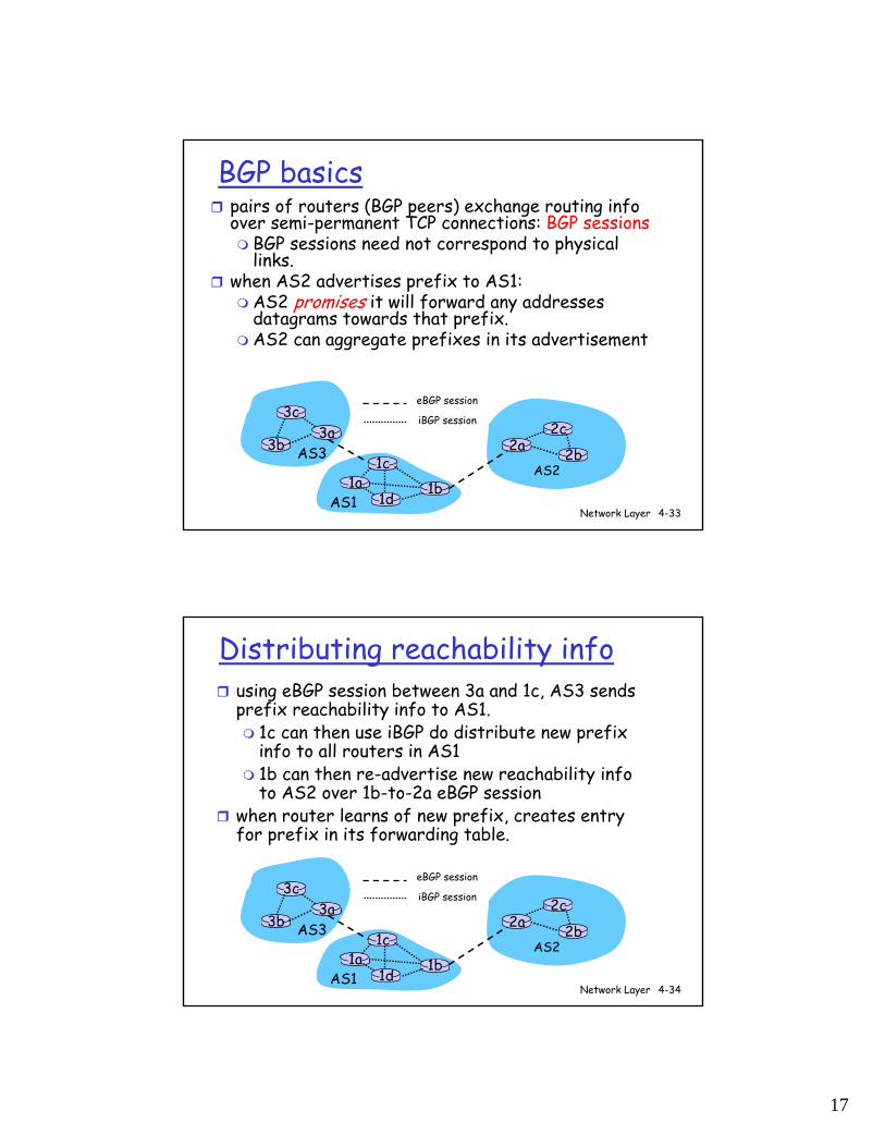
Distributing reachability infousing eBGP session between 3a and 1c, AS3 sends prefix reachability info to AS1.
1c can then use iBGP do distribute new prefix info to all routers in AS11b can then re-advertise new reachability info to AS2 over 1b-to-2a eBGP session
when router learns of new prefix, creates entry for prefix in its forwarding table.
3b
1d
3a
1c2aAS3
AS1
AS21a
2c
2b
1b
3ceBGP session
iBGP session
18
Network Layer 4-35
Path attributes & BGP routes
advertised prefix includes BGP attributes. prefix + attributes = “route”
two important attributes:AS-PATH: contains ASs through which prefix advertisement has passed: e.g, AS 67, AS 17 NEXT-HOP: indicates specific internal-AS router to next-hop AS. (may be multiple links from current AS to next-hop-AS)
when gateway router receives route advertisement, uses import policy to accept/decline.
Network Layer 4-36
BGP route selection
router may learn about more than 1 route to some prefix. Router must select route.elimination rules:
1. local preference value attribute: policy decision
2. shortest AS-PATH 3. closest NEXT-HOP router: hot potato routing4. additional criteria
19
Network Layer 4-37
BGP messages
BGP messages exchanged using TCP.BGP messages:
OPEN: opens TCP connection to peer and authenticates senderUPDATE: advertises new path (or withdraws old)KEEPALIVE keeps connection alive in absence of UPDATES; also ACKs OPEN requestNOTIFICATION: reports errors in previous msg; also used to close connection
Network Layer 4-38
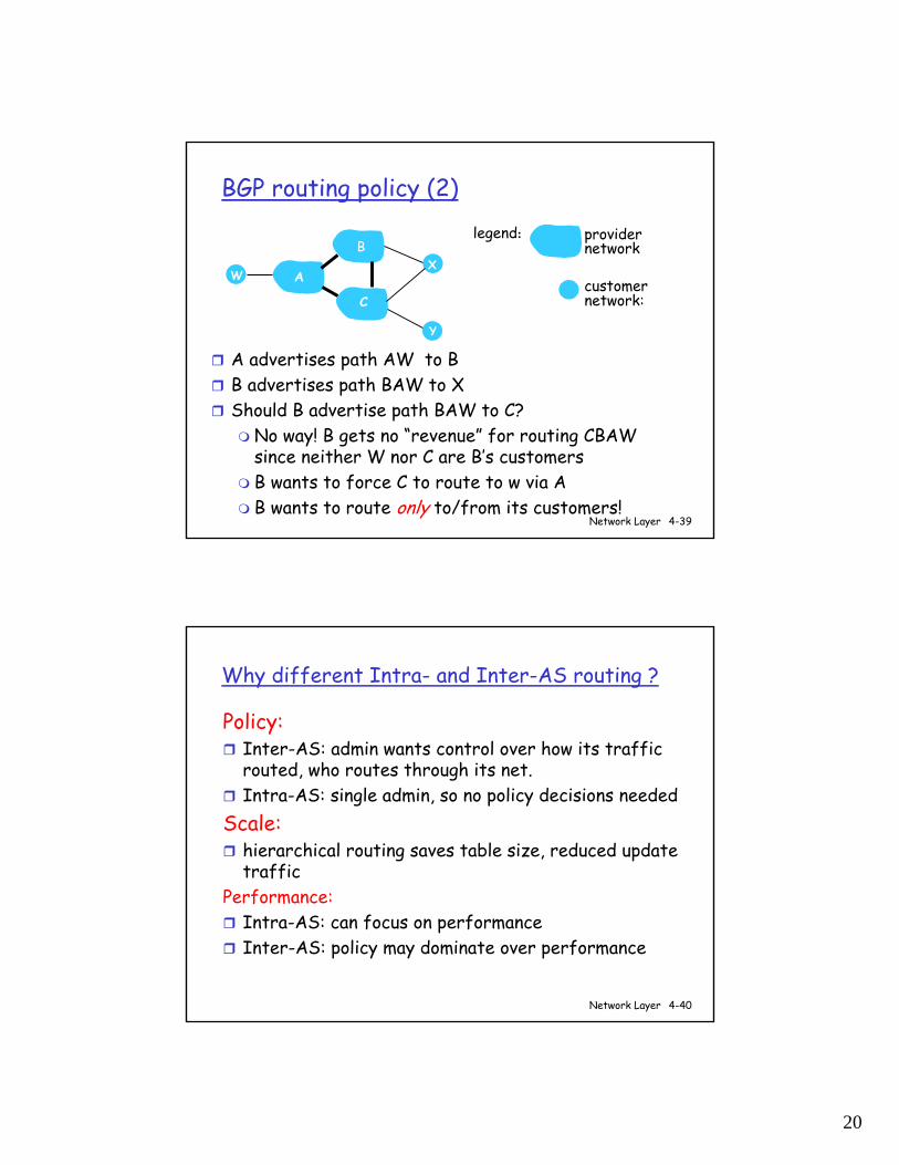
BGP routing policy
A,B,C are provider networksX,W,Y are customer (of provider networks)X is dual-homed: attached to two networks
X does not want to route from B via X to C.. so X will not advertise to B a route to C
A
B
C
WX
Y
legend:
customer network:
providernetwork
20
Network Layer 4-39
BGP routing policy (2)
A advertises path AW to BB advertises path BAW to X Should B advertise path BAW to C?
No way! B gets no “revenue” for routing CBAW since neither W nor C are B’s customers B wants to force C to route to w via AB wants to route only to/from its customers!
A
B
C
WX
Y
legend:
customer network:
providernetwork
Network Layer 4-40
Why different Intra- and Inter-AS routing ?
Policy:Inter-AS: admin wants control over how its traffic routed, who routes through its net. Intra-AS: single admin, so no policy decisions needed
Scale:hierarchical routing saves table size, reduced update traffic
Performance:Intra-AS: can focus on performanceInter-AS: policy may dominate over performance
21
Network Layer 4-41
Chapter 4: Network Layer
4. 1 Introduction4.2 Virtual circuit and datagram networks4.3 What’s inside a router4.4 IP: Internet Protocol
Datagram formatIPv4 addressingICMPIPv6
4.5 Routing algorithmsLink stateDistance VectorHierarchical routing
4.6 Routing in the Internet
RIPOSPFBGP
4.7 Broadcast and multicast routing
Network Layer 4-42
R1
R2
R3 R4
sourceduplication
R1
R2
R3 R4
in-networkduplication
duplicatecreation/transmissionduplicate
duplicate
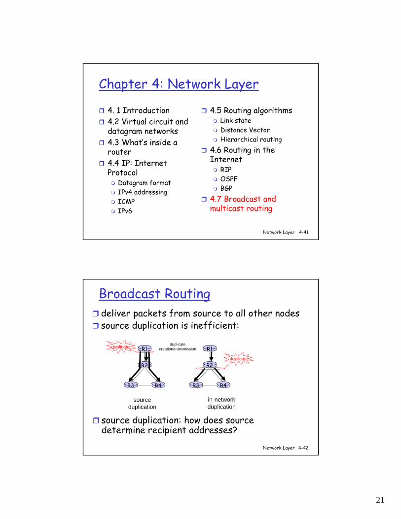
Broadcast Routingdeliver packets from source to all other nodessource duplication is inefficient:
source duplication: how does source determine recipient addresses?
22
Network Layer 4-43
In-network duplication
flooding: when node receives brdcst pckt, sends copy to all neighbors
Problems: cycles & broadcast stormcontrolled flooding: node only brdcsts pktif it hasn’t brdcst same packet before
Node keeps track of pckt ids already brdcstedOr reverse path forwarding (RPF): only forward pckt if it arrived on shortest path between node and source
spanning treeNo redundant packets received by any node
Network Layer 4-44
A
B
G
DE
c
F
A
B
G
DE
c
F
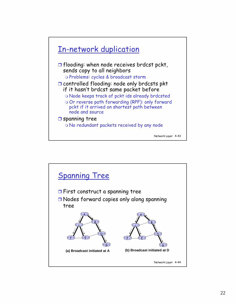
(a) Broadcast initiated at A (b) Broadcast initiated at D
Spanning Tree
First construct a spanning treeNodes forward copies only along spanning tree
23
Network Layer 4-45
A
B
G
DE
c
F1
2
3
4
5
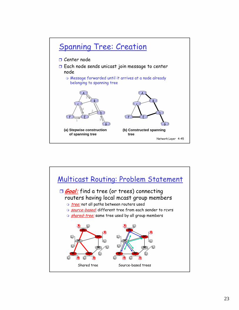
(a) Stepwise construction of spanning tree
A
B
G
DE
c
F
(b) Constructed spanning tree
Spanning Tree: CreationCenter nodeEach node sends unicast join message to center node
Message forwarded until it arrives at a node already belonging to spanning tree
Multicast Routing: Problem StatementGoal: find a tree (or trees) connecting routers having local mcast group members
tree: not all paths between routers usedsource-based: different tree from each sender to rcvrsshared-tree: same tree used by all group members
Shared tree Source-based trees
24
Approaches for building mcast trees
Approaches:source-based tree: one tree per source
shortest path treesreverse path forwarding
group-shared tree: group uses one treeminimal spanning (Steiner) center-based trees
…we first look at basic approaches, then specific protocols adopting these approaches
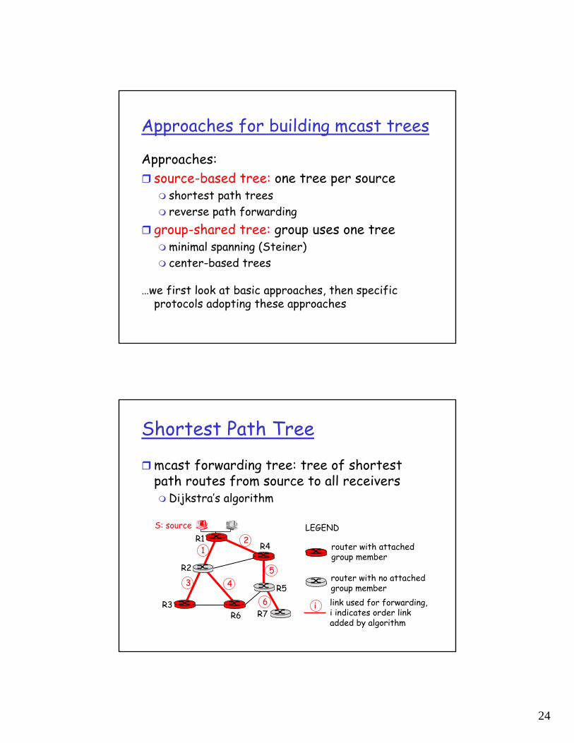
Shortest Path Tree
mcast forwarding tree: tree of shortest path routes from source to all receivers
Dijkstra’s algorithm
R1
R2
R3
R4
R5
R6 R7
21
6
3 45
i
router with attachedgroup member
router with no attachedgroup memberlink used for forwarding,i indicates order linkadded by algorithm
LEGENDS: source
25
Reverse Path Forwarding
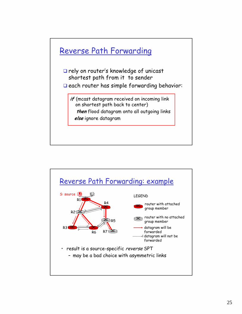
if (mcast datagram received on incoming link on shortest path back to center)then flood datagram onto all outgoing linkselse ignore datagram
rely on router’s knowledge of unicast shortest path from it to sendereach router has simple forwarding behavior:
Reverse Path Forwarding: example
• result is a source-specific reverse SPT– may be a bad choice with asymmetric links
R1
R2
R3
R4
R5
R6 R7
router with attachedgroup member
router with no attachedgroup memberdatagram will be forwarded
LEGENDS: source
datagram will not be forwarded
26
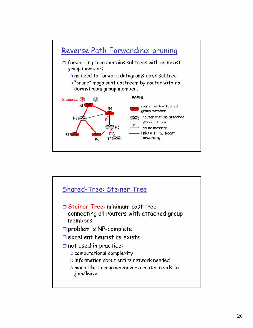
Reverse Path Forwarding: pruningforwarding tree contains subtrees with no mcast group members
no need to forward datagrams down subtree“prune” msgs sent upstream by router with no downstream group members
R1
R2
R3
R4
R5
R6 R7
router with attachedgroup memberrouter with no attachedgroup memberprune message
LEGENDS: source
links with multicastforwarding
P
P
P
Shared-Tree: Steiner Tree
Steiner Tree: minimum cost tree connecting all routers with attached group membersproblem is NP-completeexcellent heuristics existsnot used in practice:
computational complexityinformation about entire network neededmonolithic: rerun whenever a router needs to join/leave
27
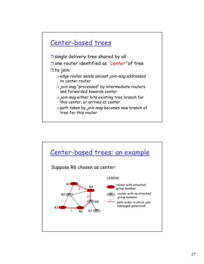
Center-based trees
single delivery tree shared by allone router identified as “center” of treeto join:
edge router sends unicast join-msg addressed to center routerjoin-msg “processed” by intermediate routers and forwarded towards centerjoin-msg either hits existing tree branch for this center, or arrives at centerpath taken by join-msg becomes new branch of tree for this router
Center-based trees: an example
Suppose R6 chosen as center:
R1
R2
R3
R4
R5
R6 R7
router with attachedgroup memberrouter with no attachedgroup memberpath order in which join messages generated
LEGEND
21
3
1
28
Internet Multicasting Routing: DVMRP
DVMRP: distance vector multicast routing protocol, RFC1075flood and prune: reverse path forwarding, source-based tree
RPF tree based on DVMRP’s own routing tables constructed by communicating DVMRP routers no assumptions about underlying unicastinitial datagram to mcast group flooded everywhere via RPFrouters not wanting group: send upstream prune msgs
DVMRP: continued…soft state: DVMRP router periodically (1 min.) “forgets” branches are pruned:
mcast data again flows down unpruned branchdownstream router: reprune or else continue to receive data
routers can quickly regraft to tree following IGMP join at leaf
odds and endscommonly implemented in commercial routersMbone routing done using DVMRP
29
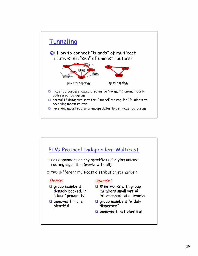
TunnelingQ: How to connect “islands” of multicast
routers in a “sea” of unicast routers?
mcast datagram encapsulated inside “normal” (non-multicast-addressed) datagramnormal IP datagram sent thru “tunnel” via regular IP unicast to receiving mcast routerreceiving mcast router unencapsulates to get mcast datagram
physical topology logical topology
PIM: Protocol Independent Multicast
not dependent on any specific underlying unicast routing algorithm (works with all)
two different multicast distribution scenarios :
Dense:group members densely packed, in “close” proximity.bandwidth more plentiful
Sparse:# networks with group members small wrt # interconnected networksgroup members “widely dispersed”bandwidth not plentiful
30
Consequences of Sparse-Dense Dichotomy:
Densegroup membership by routers assumed until routers explicitly prunedata-driven construction on mcast tree (e.g., RPF)bandwidth and non-group-router processing profligate
Sparse:no membership until routers explicitly joinreceiver- drivenconstruction of mcast tree (e.g., center-based)bandwidth and non-group-router processing conservative
PIM- Dense Mode
flood-and-prune RPF, similar to DVMRP butunderlying unicast protocol provides RPF info for incoming datagramless complicated (less efficient) downstream flood than DVMRP reduces reliance on underlying routing algorithmhas protocol mechanism for router to detect it is a leaf-node router
31
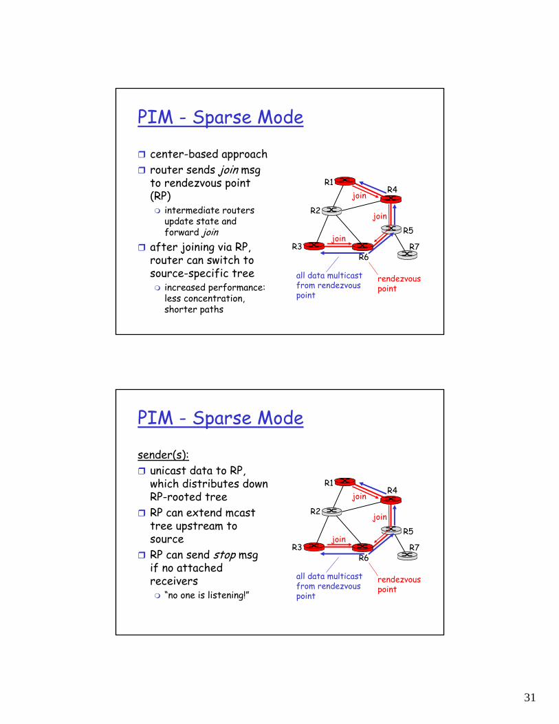
PIM - Sparse Mode
center-based approachrouter sends join msg to rendezvous point (RP)
intermediate routers update state and forward join
after joining via RP, router can switch to source-specific tree
increased performance: less concentration, shorter paths
R1
R2
R3
R4
R5
R6R7
join
join
join
all data multicastfrom rendezvouspoint
rendezvouspoint
PIM - Sparse Mode
sender(s):unicast data to RP, which distributes down RP-rooted treeRP can extend mcast tree upstream to sourceRP can send stop msg if no attached receivers
“no one is listening!”
R1
R2
R3
R4
R5
R6R7
join
join
join
all data multicastfrom rendezvouspoint
rendezvouspoint
32
Network Layer 4-63
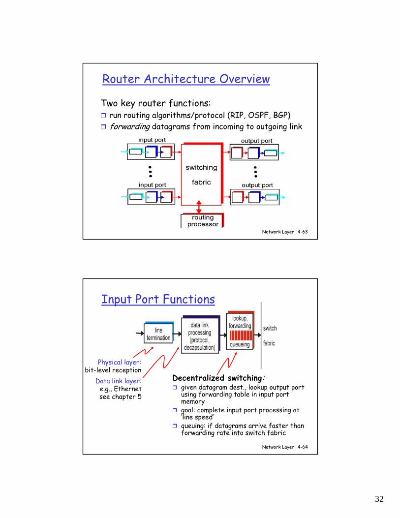
Router Architecture Overview
Two key router functions:run routing algorithms/protocol (RIP, OSPF, BGP)forwarding datagrams from incoming to outgoing link
Network Layer 4-64
Input Port Functions
Decentralized switching:given datagram dest., lookup output port using forwarding table in input port memorygoal: complete input port processing at ‘line speed’queuing: if datagrams arrive faster than forwarding rate into switch fabric
Physical layer:bit-level reception
Data link layer:e.g., Ethernetsee chapter 5
33
Network Layer 4-65
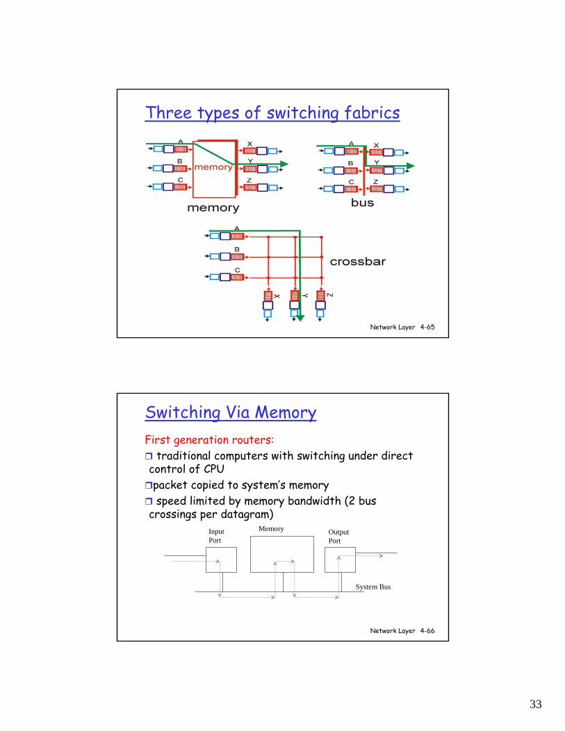
Three types of switching fabrics
Network Layer 4-66
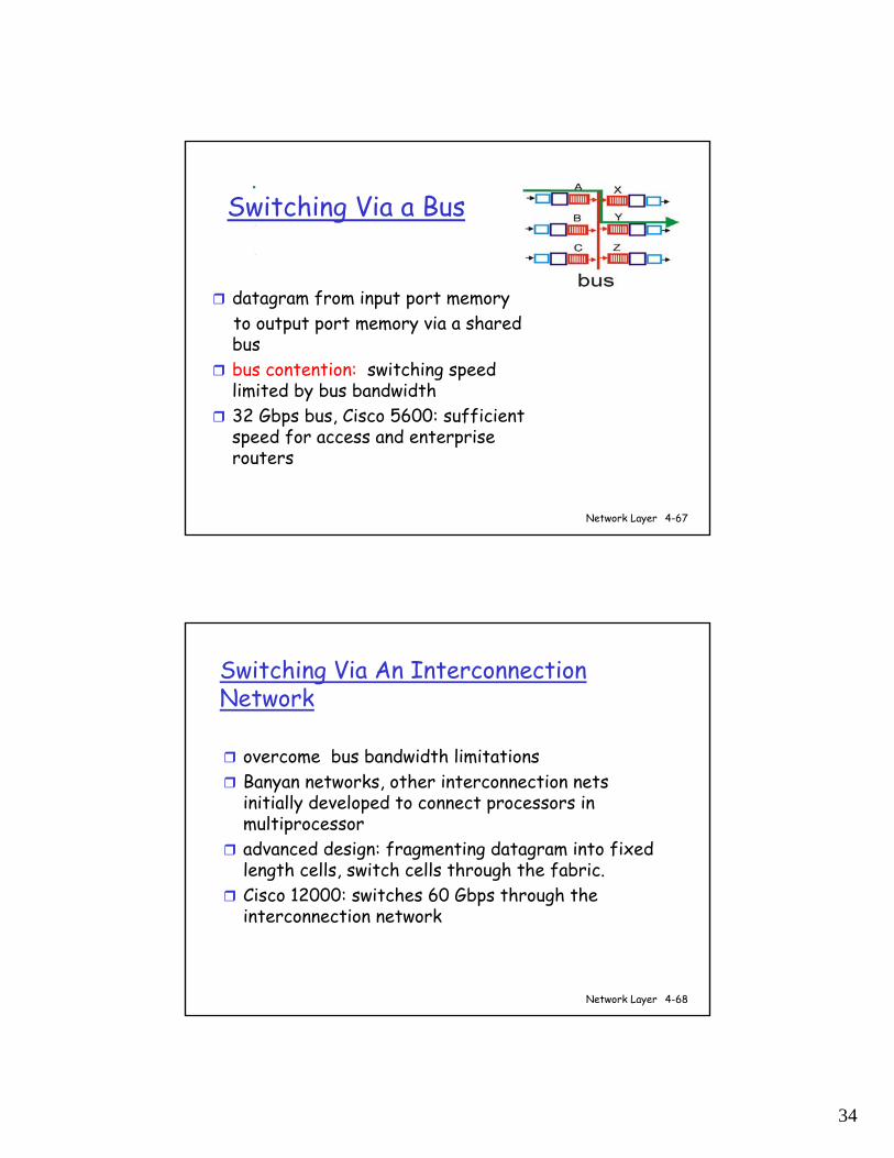
Switching Via MemoryFirst generation routers:
traditional computers with switching under direct control of CPUpacket copied to system’s memoryspeed limited by memory bandwidth (2 bus
crossings per datagram)InputPort
OutputPort
Memory
System Bus
34
Network Layer 4-67
Switching Via a Bus
datagram from input port memoryto output port memory via a shared busbus contention: switching speed limited by bus bandwidth32 Gbps bus, Cisco 5600: sufficient speed for access and enterprise routers
Network Layer 4-68
Switching Via An Interconnection Network
overcome bus bandwidth limitationsBanyan networks, other interconnection nets initially developed to connect processors in multiprocessoradvanced design: fragmenting datagram into fixed length cells, switch cells through the fabric. Cisco 12000: switches 60 Gbps through the interconnection network
35
Network Layer 4-69
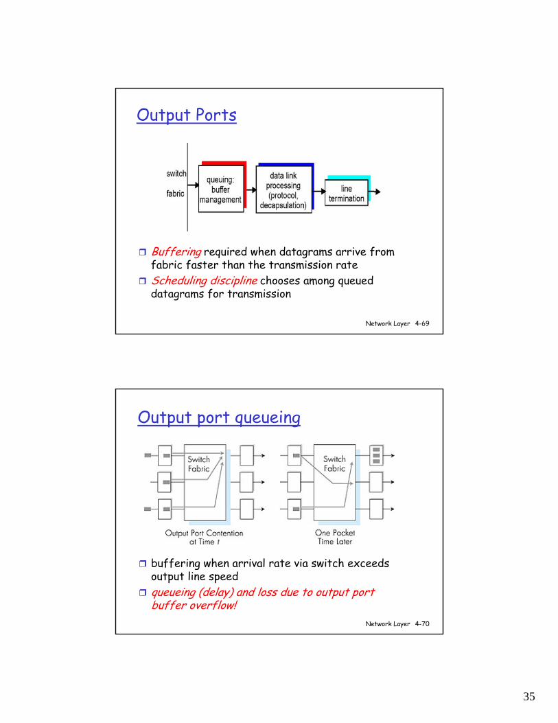
Output Ports
Buffering required when datagrams arrive from fabric faster than the transmission rateScheduling discipline chooses among queued datagrams for transmission
Network Layer 4-70
Output port queueing
buffering when arrival rate via switch exceeds output line speedqueueing (delay) and loss due to output port buffer overflow!
36
Network Layer 4-71
How much buffering?
RFC 3439 rule of thumb: average buffering equal to “typical” RTT (say 250 msec) times link capacity C
e.g., C = 10 Gps link: 2.5 Gbit bufferRecent recommendation: with N flows, buffering equal to RTT C.
N
Network Layer 4-72
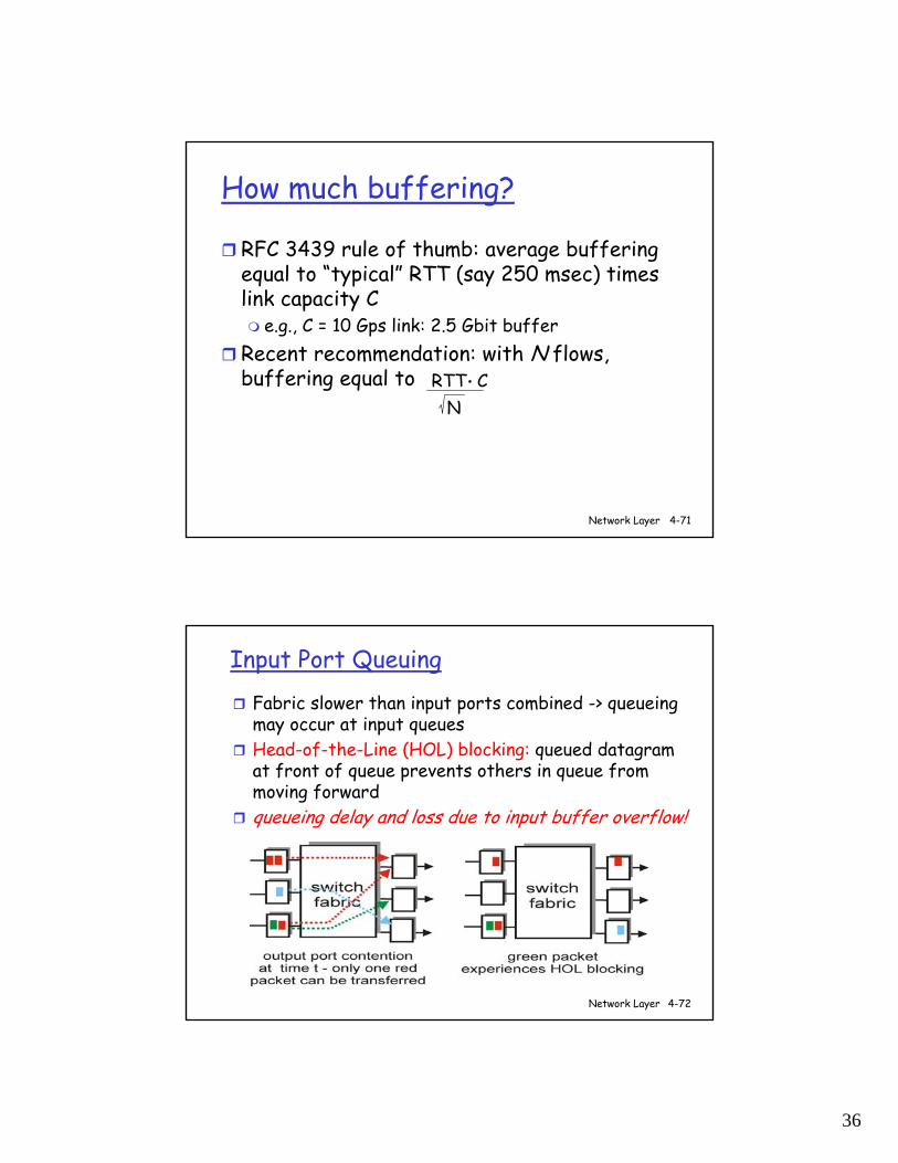
Input Port Queuing
Fabric slower than input ports combined -> queueing may occur at input queues Head-of-the-Line (HOL) blocking: queued datagram at front of queue prevents others in queue from moving forwardqueueing delay and loss due to input buffer overflow!