Embed Size (px)
Citation preview
Display unit and IR remote control
___________________
___________________
___________________
___________________
___________________
___________________
___________________
___________________
___________________
SIMATIC
EMS400S Display unit and IR remote control
Operating Instructions
09/2013 A5E03728783-03
Preface
Overview 1
Safety instructions 2
Installing and connecting the display unit
3
Control elements and displays
4
Operating devices 5
Maintenance and repairs 6
Technical specifications 7
Appendix A
Siemens AG Industry Sector Postfach 48 48 90026 NÜRNBERG GERMANY
A5E03728783-03 Ⓟ 02/2014 Technical data subject to change
Copyright © Siemens AG 2013. All rights reserved
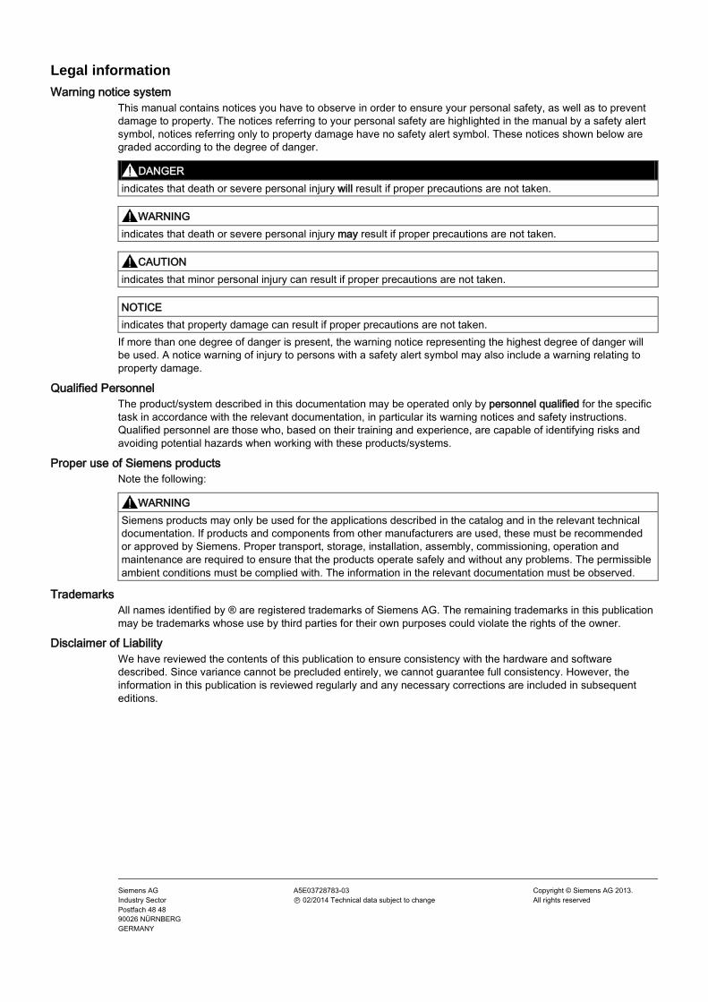
Legal information Warning notice system
This manual contains notices you have to observe in order to ensure your personal safety, as well as to prevent damage to property. The notices referring to your personal safety are highlighted in the manual by a safety alert symbol, notices referring only to property damage have no safety alert symbol. These notices shown below are graded according to the degree of danger.
DANGER indicates that death or severe personal injury will result if proper precautions are not taken.
WARNING indicates that death or severe personal injury may result if proper precautions are not taken.
CAUTION indicates that minor personal injury can result if proper precautions are not taken.
NOTICE indicates that property damage can result if proper precautions are not taken.
If more than one degree of danger is present, the warning notice representing the highest degree of danger will be used. A notice warning of injury to persons with a safety alert symbol may also include a warning relating to property damage.
Qualified Personnel The product/system described in this documentation may be operated only by personnel qualified for the specific task in accordance with the relevant documentation, in particular its warning notices and safety instructions. Qualified personnel are those who, based on their training and experience, are capable of identifying risks and avoiding potential hazards when working with these products/systems.
Proper use of Siemens products Note the following:
WARNING Siemens products may only be used for the applications described in the catalog and in the relevant technical documentation. If products and components from other manufacturers are used, these must be recommended or approved by Siemens. Proper transport, storage, installation, assembly, commissioning, operation and maintenance are required to ensure that the products operate safely and without any problems. The permissible ambient conditions must be complied with. The information in the relevant documentation must be observed.
Trademarks All names identified by ® are registered trademarks of Siemens AG. The remaining trademarks in this publication may be trademarks whose use by third parties for their own purposes could violate the rights of the owner.
Disclaimer of Liability We have reviewed the contents of this publication to ensure consistency with the hardware and software described. Since variance cannot be precluded entirely, we cannot guarantee full consistency. However, the information in this publication is reviewed regularly and any necessary corrections are included in subsequent editions.
Display unit and IR remote control Operating Instructions, 09/2013, A5E03728783-03 3
Preface
Purpose of the operating instructions These operating instructions provide information based on the documentation requirements specified in IEC 62079. This information relates to the place of use, transport, storage, mounting, use and maintenance.
These operating instructions are intended for:
● Commissioning engineers
● Operators
● Maintenance personnel
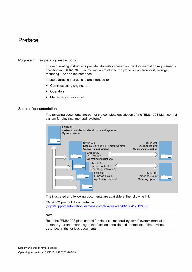
Scope of documentation The following documents are part of the complete description of the "EMS400S plant control system for electrical monorail systems":
The illustrated and following documents are available at the following link:
EMS400S product documentation (http://support.automation.siemens.com/WW/view/en/68156412/133300)
Note
Read the "EMS400S plant control for electrical monorail systems" system manual to enhance your understanding of the function principle and interaction of the devices described in the various documents.
Preface
Display unit and IR remote control 4 Operating Instructions, 09/2013, A5E03728783-03
The documents contain links to other relevant documents for Siemens standard modules that are used for the electrical monorail system. The "S7-1200 Automation System" System Manual for the SIMATIC S7 CPU is of ultimate importance in this context.
Scope This documents applies to:
● SIMATIC EMS400S Diagnostics Unit, Order Number 6ES7292-0AA50-0AA0
● SIMATIC EMS400S IR remote control, order number 6ES7292-0CA50-0AA0
Note
Observe the following points: • This document supplements the "EMS400S plant control system for electrical monorail
systems" system manual. • You are also going to need this document whenever the system is recommissioned. Keep
this and supplementary documentation in a safe place for the entire life cycle of the device.
• Submit all of these documents to a future owner of the device.
Knowledge required General knowledge in the fields of electrical engineering, automation technology and process communication is prerequisite for comprehension of this documentation. This includes knowledge of the "TIA Portal" engineering software.
Style conventions Notation Scope "Add screen" • Terminology for the user interface, e.g. dialog name, tab,
button, menu command • Necessary entries, e.g. limit value, tag value • Path information
"File > Edit" Operational sequences, e.g, menu command, shortcut menu command
Please observe notes labeled as follows:
Note
A note contains important information about the product described in the document and its handling, or a specific section of the document to which you should pay particular attention.
Preface
Display unit and IR remote control Operating Instructions, 09/2013, A5E03728783-03 5
Naming conventions Term Applies to Device • Display unit
• IR remote control
Control cabinet • Installation cabinet • Enclosure • Terminal box • Console • Switchboard
Figures This document contains illustrations of the described devices. The illustrations may deviate from the particularities of the delivered device.
Preface
Display unit and IR remote control 6 Operating Instructions, 09/2013, A5E03728783-03
Display unit and IR remote control Operating Instructions, 09/2013, A5E03728783-03 7
Table of contents
Preface ................................................................................................................................................... 3
1 Overview................................................................................................................................................. 9
1.1 Display unit ..................................................................................................................................... 9 1.1.1 Product overview............................................................................................................................ 9 1.1.2 Scope of delivery.......................................................................................................................... 10 1.1.3 Accessories .................................................................................................................................. 10
1.2 IR remote control.......................................................................................................................... 11 1.2.1 Product overview.......................................................................................................................... 11 1.2.2 Scope of delivery.......................................................................................................................... 11
2 Safety instructions ................................................................................................................................. 13
2.1 Safety instructions ........................................................................................................................ 13
2.2 IT security notes ........................................................................................................................... 15
3 Installing and connecting the display unit ............................................................................................... 17
3.1 Check the scope of delivery ......................................................................................................... 17
3.2 Permitted mounting positions ....................................................................................................... 17
3.3 Mounting location and clearances ............................................................................................... 19
3.4 Installing the display unit .............................................................................................................. 21
3.5 Wiring information ........................................................................................................................ 23
3.6 Interfaces ..................................................................................................................................... 24
3.7 Connecting interfaces .................................................................................................................. 24 3.7.1 Connecting functional ground ...................................................................................................... 24 3.7.2 Wiring the power supply ............................................................................................................... 27
3.8 Installing and wiring an external infrared sensor ......................................................................... 28
3.9 Securing the cables ..................................................................................................................... 28
4 Control elements and displays .............................................................................................................. 29
4.1 Display unit ................................................................................................................................... 29
4.2 IR remote control.......................................................................................................................... 30 4.2.1 Check the scope of delivery ......................................................................................................... 30 4.2.2 Layout the IR remote control ........................................................................................................ 31 4.2.3 Transmission range of the IR remote control and signal transmission ........................................ 32
Table of contents
Display unit and IR remote control 8 Operating Instructions, 09/2013, A5E03728783-03
5 Operating devices ................................................................................................................................. 33
5.1 Operating the display unit ........................................................................................................... 33
5.2 Operating the IR remote control .................................................................................................. 35 5.2.1 Inserting and changing batteries ................................................................................................. 35 5.2.2 Checking the battery charge ....................................................................................................... 36 5.2.3 Adjusting brightness .................................................................................................................... 37 5.2.4 Function principle and functional scope ...................................................................................... 38
6 Maintenance and repairs ....................................................................................................................... 39
7 Technical specifications ........................................................................................................................ 41
7.1 Display unit .................................................................................................................................. 41 7.1.1 Dimensional diagram .................................................................................................................. 41 7.1.2 Technical specifications .............................................................................................................. 42 7.1.3 Interface description .................................................................................................................... 43 7.1.3.1 Power supply interface ................................................................................................................ 43 7.1.3.2 Interface for external infrared sensor .......................................................................................... 43 7.1.3.3 Data exchange interface ............................................................................................................. 44
7.2 IR remote control ......................................................................................................................... 45 7.2.1 Dimensional diagram .................................................................................................................. 45 7.2.2 Technical specifications .............................................................................................................. 46
7.3 Approvals .................................................................................................................................... 47
7.4 Notes about usage ...................................................................................................................... 48
7.5 Electromagnetic compatibility...................................................................................................... 49
7.6 Environmental conditions ............................................................................................................ 51 7.6.1 Transportation and storage requirements ................................................................................... 51 7.6.2 Operational requirements ............................................................................................................ 52 7.6.3 Tests for compliance with environmental conditions .................................................................. 53
A Appendix .............................................................................................................................................. 55
A.1 Technical support ........................................................................................................................ 55
A.2 Abbreviations .............................................................................................................................. 56
Index .................................................................................................................................................... 57
Display unit and IR remote control Operating Instructions, 09/2013, A5E03728783-03 9
Overview 1 1.1 Display unit
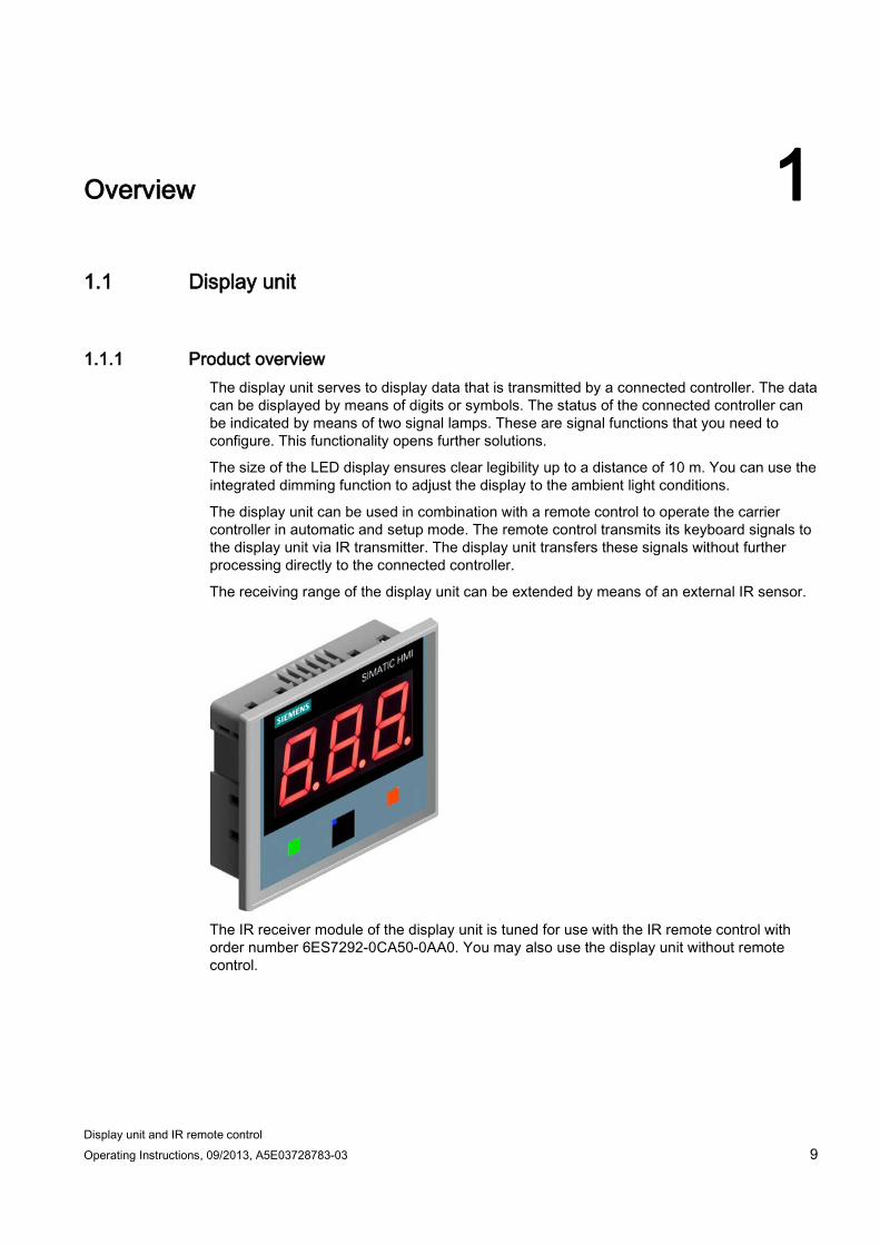
1.1.1 Product overview The display unit serves to display data that is transmitted by a connected controller. The data can be displayed by means of digits or symbols. The status of the connected controller can be indicated by means of two signal lamps. These are signal functions that you need to configure. This functionality opens further solutions.
The size of the LED display ensures clear legibility up to a distance of 10 m. You can use the integrated dimming function to adjust the display to the ambient light conditions.
The display unit can be used in combination with a remote control to operate the carrier controller in automatic and setup mode. The remote control transmits its keyboard signals to the display unit via IR transmitter. The display unit transfers these signals without further processing directly to the connected controller.
The receiving range of the display unit can be extended by means of an external IR sensor.
The IR receiver module of the display unit is tuned for use with the IR remote control with order number 6ES7292-0CA50-0AA0. You may also use the display unit without remote control.
Overview 1.1 Display unit
Display unit and IR remote control 10 Operating Instructions, 09/2013, A5E03728783-03
1.1.2 Scope of delivery The scope of delivery of the display unit includes:
● 1 × display unit
● 1 x accessory pack with the following contents:
– 4 clamping brackets
– 4 threaded pins for the clamping brackets
– 1 mains terminal for the power supply
1.1.3 Accessories The following accessories are available on order:
● IR remote control
The IR remote control represents the input device for the display unit. It is available under order number 6ES7292-0CA50-0AA0.
● Infrared sensor
The IR sensor is used to extend the range of the IR receiver of the display unit. It is available under order number 6ES7292-0AA55-0AA0.
Orders for accessories can be place t the following link:
Industry Mall (http://mall.automation.siemens.com)
Overview 1.2 IR remote control
Display unit and IR remote control Operating Instructions, 09/2013, A5E03728783-03 11
1.2 IR remote control
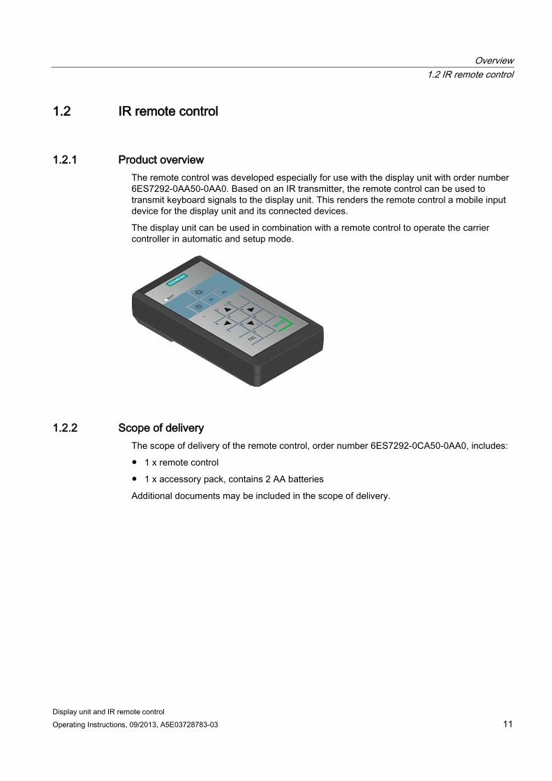
1.2.1 Product overview The remote control was developed especially for use with the display unit with order number 6ES7292-0AA50-0AA0. Based on an IR transmitter, the remote control can be used to transmit keyboard signals to the display unit. This renders the remote control a mobile input device for the display unit and its connected devices.
The display unit can be used in combination with a remote control to operate the carrier controller in automatic and setup mode.
1.2.2 Scope of delivery The scope of delivery of the remote control, order number 6ES7292-0CA50-0AA0, includes:
● 1 x remote control
● 1 x accessory pack, contains 2 AA batteries
Additional documents may be included in the scope of delivery.
Overview 1.2 IR remote control
Display unit and IR remote control 12 Operating Instructions, 09/2013, A5E03728783-03
Display unit and IR remote control Operating Instructions, 09/2013, A5E03728783-03 13
Safety instructions 2 2.1 Safety instructions
WARNING
Injury or material damage
You risk the development of danger sources and deactivation of safety functions if you neglect the safety and handling instructions provided in this document. This can result in personal injuries or material damage.
Strictly adhere to the safety and handling instructions.
Always adhere to the safety instructions and accident prevention regulations for the respective application, independent of the safety instructions provided in this document.
Safety during commissioning and operation Observe the relevant safety guidelines when using the devices in an EMS plant. For more information, refer to chapter "Safety instructions" in the "EMS400S trolley controller for EMS plants" system manual.
The documents belonging to the devices are listed in the preface.
WARNING
Installation/use as intended
It is strictly forbidden to commission the device before compliance with Machinery Directive 2006/42/E has been verified for the machine to be operated with this device.
Verify before commissioning that the provisions of Directive 2006/42/EC are fulfilled.
Safety instructions 2.1 Safety instructions
Display unit and IR remote control 14 Operating Instructions, 09/2013, A5E03728783-03
Safety when working in and on electrical systems Only authorized persons are allowed to work in or on electrical equipment. The following safety regulations for prevention of electrical shock are valid in Germany:
1. Isolation of the system from power
2. Securing the system against restart
3. Verification of isolation from power at all poles
4. Grounding and shorting the system
5. Covering or fencing off adjacent live parts
These safety regulations are based on DIN VDE 0105.
Note
The safety regulations must be applied in the aforementioned order before any work is carried out on electrical systems. The safety regulations must be applied in reverse order on completion of all tasks on the electrical system.
Identify the electrical system in accordance with valid safety regulations when working on this system.
Observe the valid safety regulations of the respective country.
Safety during operation
Note
High-frequency radiation, e.g. from cellular phones, may cause unwanted operating states in the plant.
Warranty Prerequisites for trouble-free and safe operation of the device:
● Proper transportation and storage
● Proper mounting and wiring
● Proper operation and repairs
Non-compliance with these regulations shall render the device warranty void.
ESD An ESD (Electrostatically Sensitive Device) is equipped with electronic components. Due to their design, electronic components are highly sensitive to overvoltage and electrostatic discharge. Observer the regulations governing the handling of ESD components.
Safety instructions 2.2 IT security notes
Display unit and IR remote control Operating Instructions, 09/2013, A5E03728783-03 15
2.2 IT security notes Siemens offers IT security mechanisms for its portfolio of automation and drive products in order to support safe operation of the plant/machine. We recommend that you stay informed about the IT security developments for your products. For information on this topic, refer to: Industry Online Support (http://www.siemens.de/automation/csi_en_WW): You can register for a product-specific newsletter here.
For the safe operation of a plant/machine, however, it is also necessary to integrate the automation components into an overall IT security concept for the entire plant/machine, which corresponds to the state-of-the-art IT technology. You can find information on this under: Industrial Security (http://www.siemens.com/industrialsecurity).
Products used from other manufacturers should also be taken into account here.
Safety instructions 2.2 IT security notes
Display unit and IR remote control 16 Operating Instructions, 09/2013, A5E03728783-03
Display unit and IR remote control Operating Instructions, 09/2013, A5E03728783-03 17
Installing and connecting the display unit 3 3.1 Check the scope of delivery
Check the scope of delivery for completeness and visible signs of transport damage.
Note
You risk malfunctions if using faulty parts that have were delivered to you. Always use part that do not disclose any fault. Contact your Siemens partner for support for faulty parts.
3.2 Permitted mounting positions
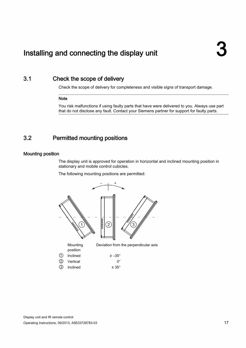
Mounting position The display unit is approved for operation in horizontal and inclined mounting position in stationary and mobile control cubicles.
The following mounting positions are permitted:
Mounting
position Deviation from the perpendicular axis
① Inclined ≥ –35° ② Vertical 0° ③ Inclined ≤ 35°
Installing and connecting the display unit 3.2 Permitted mounting positions
Display unit and IR remote control 18 Operating Instructions, 09/2013, A5E03728783-03
The display unit is quipped with venting slots for heat convection into the control cabinet where thermal energy is dissipated on the panels of the control cabinet.
Note
You risk damage to the display unit if operating it outside the approved ambient temperature limits. The approvals and warranty for the display unit shall be rendered void in this case.
Mobile operation
Note
Note that the mounting position may only be exceeded on a short-term basis during mobile operation.
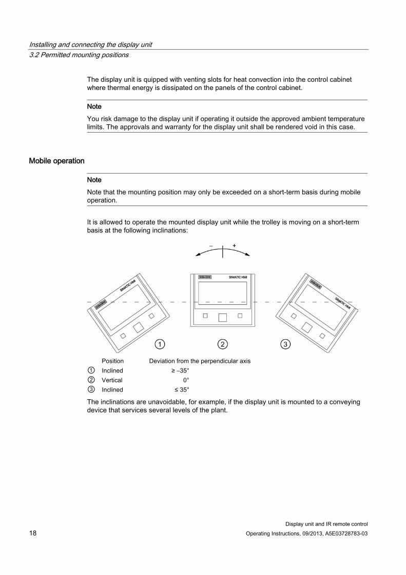
It is allowed to operate the mounted display unit while the trolley is moving on a short-term basis at the following inclinations:
Position Deviation from the perpendicular axis ① Inclined ≥ –35° ② Vertical 0° ③ Inclined ≤ 35°
The inclinations are unavoidable, for example, if the display unit is mounted to a conveying device that services several levels of the plant.
Installing and connecting the display unit 3.3 Mounting location and clearances
Display unit and IR remote control Operating Instructions, 09/2013, A5E03728783-03 19
3.3 Mounting location and clearances
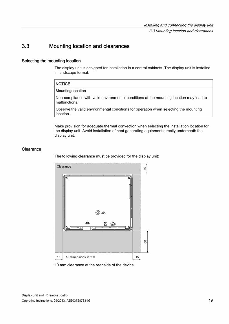
Selecting the mounting location The display unit is designed for installation in a control cabinets. The display unit is installed in landscape format.
NOTICE
Mounting location
Non-compliance with valid environmental conditions at the mounting location may lead to malfunctions.
Observe the valid environmental conditions for operation when selecting the mounting location.
Make provision for adequate thermal convection when selecting the installation location for the display unit. Avoid installation of heat generating equipment directly underneath the display unit.
Clearance The following clearance must be provided for the display unit:
10 mm clearance at the rear side of the device.
Installing and connecting the display unit 3.3 Mounting location and clearances
Display unit and IR remote control 20 Operating Instructions, 09/2013, A5E03728783-03
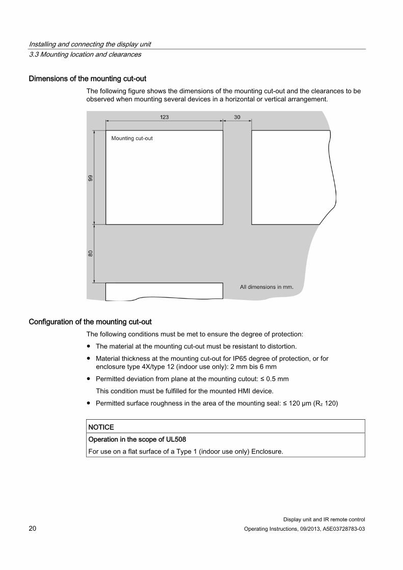
Dimensions of the mounting cut-out The following figure shows the dimensions of the mounting cut-out and the clearances to be observed when mounting several devices in a horizontal or vertical arrangement.
Configuration of the mounting cut-out The following conditions must be met to ensure the degree of protection:
● The material at the mounting cut-out must be resistant to distortion.
● Material thickness at the mounting cut-out for IP65 degree of protection, or for enclosure type 4X/type 12 (indoor use only): 2 mm bis 6 mm
● Permitted deviation from plane at the mounting cutout: ≤ 0.5 mm
This condition must be fulfilled for the mounted HMI device.
● Permitted surface roughness in the area of the mounting seal: ≤ 120 µm (Rz 120)
NOTICE
Operation in the scope of UL508
For use on a flat surface of a Type 1 (indoor use only) Enclosure.
Installing and connecting the display unit 3.4 Installing the display unit
Display unit and IR remote control Operating Instructions, 09/2013, A5E03728783-03 21
3.4 Installing the display unit Clamping brackets are provided for mounting the display unit in a control cabinet. These prevent the main dimensions of the display unit from being exceeded. Always adhere to the specifications in these operating instructions when installing the display unit.
Requirement ● 4 clamping brackets
The clamping brackets are included in the accessory kit.
Procedure
Note Mounting the clamping brackets
You will risk damage to the enclosure of device if you continue to turn the mounting screw while the gap between the device and the panel of the control cabinet is already closed.
Once the gap is closed, do not turn the mounting screw any further. You may also tighten the clamping bracket with a torque wrench set to ≤ 0.2 N/m. Risk of the loss of the guaranteed degree of protection
The degree of protection is not insured if the mounting seal is not installed, or if it is damaged or improperly inserted.
Check the presence, condition and seating of the mounting seal.
Installing and connecting the display unit 3.5 Wiring information
Display unit and IR remote control 22 Operating Instructions, 09/2013, A5E03728783-03
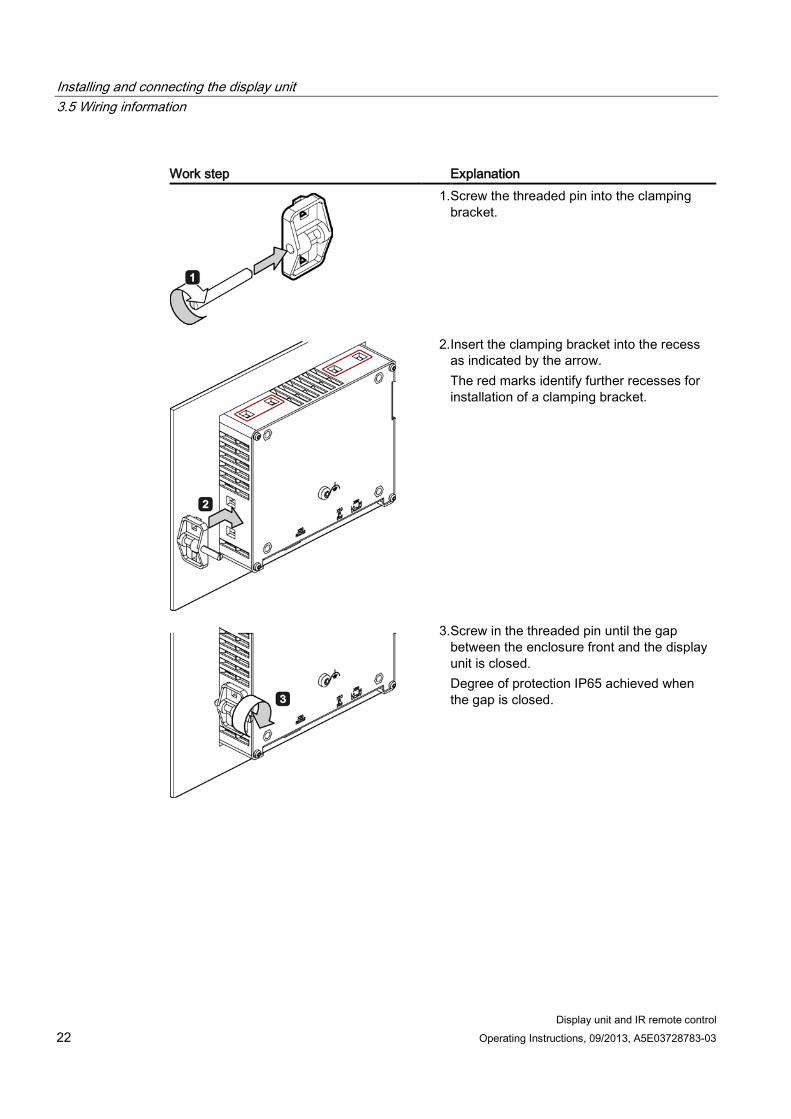
Work step Explanation
1. Screw the threaded pin into the clamping bracket.
2. Insert the clamping bracket into the recess as indicated by the arrow. The red marks identify further recesses for installation of a clamping bracket.
3. Screw in the threaded pin until the gap between the enclosure front and the display unit is closed. Degree of protection IP65 achieved when the gap is closed.
Installing and connecting the display unit 3.5 Wiring information
Display unit and IR remote control Operating Instructions, 09/2013, A5E03728783-03 23
3.5 Wiring information
Wiring sequence
Note
You will risk damage to the device if you ignore the specified wiring sequence.
Wire the device in the following sequence:
1. Functional ground
2. Power supply
3. I/O devices
You can disconnect the device in reverse order.
Note Device failure
Moisture and condensation lead to malfunction. Moisture in the form of condensation on or in the device is formed: • When transporting a device at low temperatures • Under extreme temperature variations
Bring the device to room temperature before operating. Condensation
Do not expose the device to direct heat radiation from a heater.
If condensation has developed, wait approximately 4 hours until the HMI device has dried completely before switching it on.
Wiring cables Make sure that you do not bend the pins when connecting the cables. Secure the cables and connectors using the fixation facilities provided.
Note
You will risk malfunctions if using cables that are not approved.
Always use shielded standard cables for data transmission. Orders for accessories can be placed at the following Internet URL:
Industry Mall (http://mall.automation.siemens.com)
Installing and connecting the display unit 3.6 Interfaces
Display unit and IR remote control 24 Operating Instructions, 09/2013, A5E03728783-03
3.6 Interfaces
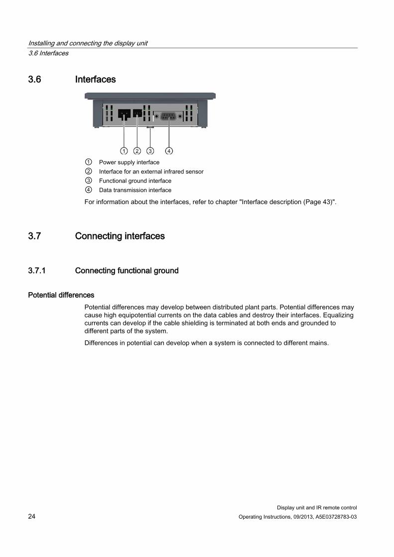
① Power supply interface ② Interface for an external infrared sensor ③ Functional ground interface ④ Data transmission interface
For information about the interfaces, refer to chapter "Interface description (Page 43)".
3.7 Connecting interfaces
3.7.1 Connecting functional ground
Potential differences Potential differences may develop between distributed plant parts. Potential differences may cause high equipotential currents on the data cables and destroy their interfaces. Equalizing currents can develop if the cable shielding is terminated at both ends and grounded to different parts of the system.
Differences in potential can develop when a system is connected to different mains.
Installing and connecting the display unit 3.7 Connecting interfaces
Display unit and IR remote control Operating Instructions, 09/2013, A5E03728783-03 25
General requirements of equipotential bonding You must reduce potential differences to the possible minimum by installing equipotential conductors to ensure proper functioning of the respective electronic components. For this reason, observe the following rules when installing the equipotential bonding circuit:
● The effectiveness of equipotential bonding increases proportionally with lower impedance or greater cross-section of the equipotential bonding conductor.
● If two plant components are interconnected by means of shielded data cables and their shielding is grounded at both ends, the impedance of the additionally installed equipotential bonding conductor may not exceed 10 % of the shielding impedance.
● The cross-section of an equipotential bonding conductor must be of sufficient size to cope with the maximum equipotential current.
In practical life, equipotential bonding conductors with a minimum cross-section of 16 mm² are generally accepted for the interconnection between control cabinets or with grounding busbars.
● Use equipotential bonding conductors made of copper or galvanized steel.
Interconnect the equipotential bonding conductors and the earth rod/protective conductor on a large surface and protect these against corrosion.
● Use a suitable cable clamp to bond the shielding of the data cable flush to the equipotential busbar. Keep the length of cable between the device and the equipotential bonding rail as short as possible.
● Route the equipotential bonding conductors and data cables in parallel and with minimum clearance between them.
Installing and connecting the display unit 3.7 Connecting interfaces
Display unit and IR remote control 26 Operating Instructions, 09/2013, A5E03728783-03
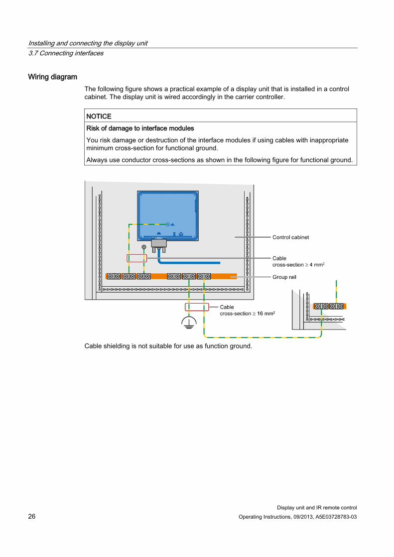
Wiring diagram The following figure shows a practical example of a display unit that is installed in a control cabinet. The display unit is wired accordingly in the carrier controller.
NOTICE
Risk of damage to interface modules
You risk damage or destruction of the interface modules if using cables with inappropriate minimum cross-section for functional ground.
Always use conductor cross-sections as shown in the following figure for functional ground.
Cable shielding is not suitable for use as function ground.
Installing and connecting the display unit 3.7 Connecting interfaces
Display unit and IR remote control Operating Instructions, 09/2013, A5E03728783-03 27
3.7.2 Wiring the power supply
Power supply
NOTICE
Safe electrical isolation
Use only 24 V DC power supply units with safe electrical isolation in accordance with IEC 60364-4-41 or HD 384.04.41 (VDE 0100, Part 410), for example, in accordance with the PELV standard.
The supply voltage must be within the specified voltage range. Incorrect voltage may cause function failures on the device.
Note
Provide an external fusing of ≤ 4.0 A for the 24 V DC input of the display unit.
Applies to non-isolated system design:
Note
Wire the 24 V GND connection of the DC-24-V output of the power supply to the equipotential bus to achieve a uniform reference potential. Select a central termination point as far as possible.
Wiring the mains terminal block The mains terminal block for wiring the power supply is included in your package. The mains terminal block is designed for conductor cross-sections from 0.25 mm² to 2.5 mm².
Note
Always use wires with a conductor cross-section of ≥ 0.5 mm².
You can terminate solid or stranded wires. Wire end ferrules are not required.
Note Damage to the display unit
Do not tighten the screws of the main terminal block while it is inserted in the device. You risk damage to the device due to the pressure of the screwdriver on the main terminal block and its socket.
Always remove the main terminal block to terminate the wires.
Installing and connecting the display unit 3.8 Installing and wiring an external infrared sensor
Display unit and IR remote control 28 Operating Instructions, 09/2013, A5E03728783-03
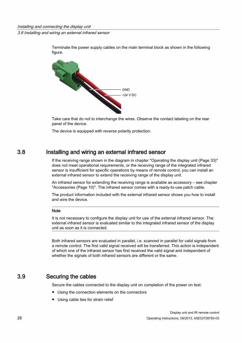
Terminate the power supply cables on the main terminal block as shown in the following figure.
Take care that do not to interchange the wires. Observe the contact labeling on the rear panel of the device.
The device is equipped with reverse polarity protection.
3.8 Installing and wiring an external infrared sensor If the receiving range shown in the diagram in chapter "Operating the display unit (Page 33)" does not meet operational requirements, or the receiving range of the integrated infrared sensor is insufficient for specific operations by means of remote control, you can install an external infrared sensor to extend the receiving range of the display unit.
An infrared sensor for extending the receiving range is available as accessory – see chapter "Accessories (Page 10)". The infrared sensor comes with a ready-to-use patch cable.
The product information included with the external infrared sensor shows you how to install and wire the device.
Note
It is not necessary to configure the display unit for use of the external infrared sensor. The external infrared sensor is evaluated similar to the integrated infrared sensor of the display unit as soon as it is connected.
Both infrared sensors are evaluated in parallel, i.e. scanned in parallel for valid signals from a remote control. The first valid signal received will be transferred. This action is independent of which one of the infrared sensor has first received the valid signal and independent of whether the signals of both infrared sensors are different or the same.
3.9 Securing the cables Secure the cables connected to the display unit on completion of the power on test:
● Using the connection elements on the connectors
● Using cable ties for strain relief
Display unit and IR remote control Operating Instructions, 09/2013, A5E03728783-03 29
Control elements and displays 4 4.1 Display unit
The specific information to be displayed on the display unit depends on the configuration of the connected controller. This configuration also applies to the LED display and signal lamps.
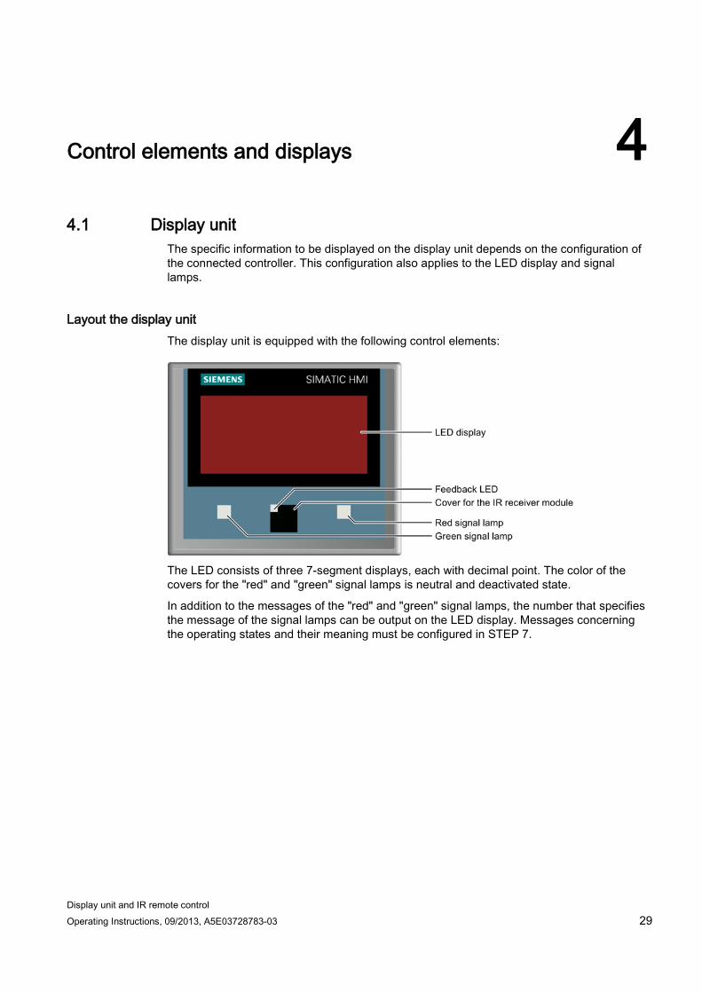
Layout the display unit The display unit is equipped with the following control elements:
The LED consists of three 7-segment displays, each with decimal point. The color of the covers for the "red" and "green" signal lamps is neutral and deactivated state.
In addition to the messages of the "red" and "green" signal lamps, the number that specifies the message of the signal lamps can be output on the LED display. Messages concerning the operating states and their meaning must be configured in STEP 7.
Control elements and displays 4.2 IR remote control
Display unit and IR remote control 30 Operating Instructions, 09/2013, A5E03728783-03
LED display The characters were selected to display acronyms in the following form:
● Err – for errors
● F05 – for error number 05
● Pr1 – for process 1
● 1-3 – for station 1 to 3
Signal lamps The signal lamps are suitable, for example to indicate the following states:
● Error state
● Current operating state
Whether or not the controller transmits specific messages to the display unit depends on the configuration in STEP 7.
Feedback LED This LED indicates that a valid signal was received from a remote control.
4.2 IR remote control
4.2.1 Check the scope of delivery Check the scope of delivery for completeness and visible signs of transport damage.
Note
You risk malfunctions if using faulty parts that have were delivered to you. Always use part that do not disclose any fault. Contact your Siemens partner for support for faulty parts.
Control elements and displays 4.2 IR remote control
Display unit and IR remote control Operating Instructions, 09/2013, A5E03728783-03 31
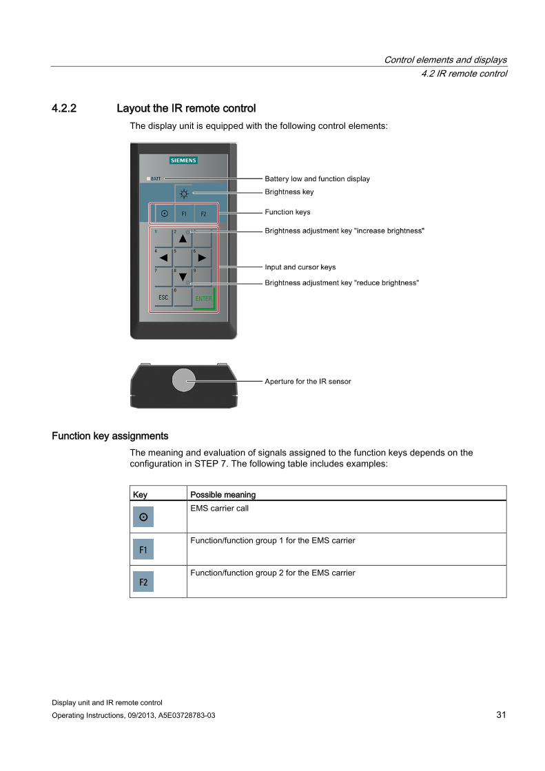
4.2.2 Layout the IR remote control The display unit is equipped with the following control elements:
Function key assignments The meaning and evaluation of signals assigned to the function keys depends on the configuration in STEP 7. The following table includes examples:
Key Possible meaning
EMS carrier call
Function/function group 1 for the EMS carrier
Function/function group 2 for the EMS carrier
Control elements and displays 4.2 IR remote control
Display unit and IR remote control 32 Operating Instructions, 09/2013, A5E03728783-03
Assignment of the input and cursor keys The meaning and evaluation of the signals of keys and keystrokes assigned in the Step 7 program depends on the configuration in STEP 7. More information is available in the system manual "EMS400S plant control system for electrical monorail systems".
The number of input or cursor key signals that can be used standalone or in combination with a second key is specified in chapter "Function principle and functional scope (Page 38)".
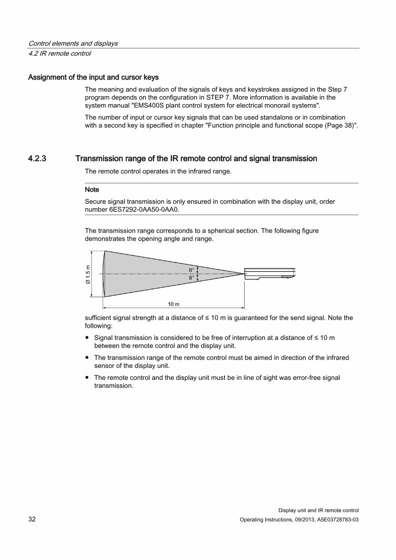
4.2.3 Transmission range of the IR remote control and signal transmission The remote control operates in the infrared range.
Note
Secure signal transmission is only ensured in combination with the display unit, order number 6ES7292-0AA50-0AA0.
The transmission range corresponds to a spherical section. The following figure demonstrates the opening angle and range.
sufficient signal strength at a distance of ≤ 10 m is guaranteed for the send signal. Note the following:
● Signal transmission is considered to be free of interruption at a distance of ≤ 10 m between the remote control and the display unit.
● The transmission range of the remote control must be aimed in direction of the infrared sensor of the display unit.
● The remote control and the display unit must be in line of sight was error-free signal transmission.
Display unit and IR remote control Operating Instructions, 09/2013, A5E03728783-03 33
Operating devices 5 5.1 Operating the display unit
You always need to use the remote control to enter control commands via the display unit. It is not possible to enter control commands directly at the display unit. For information about the remote control, refer to chapter "Accessories (Page 10)".
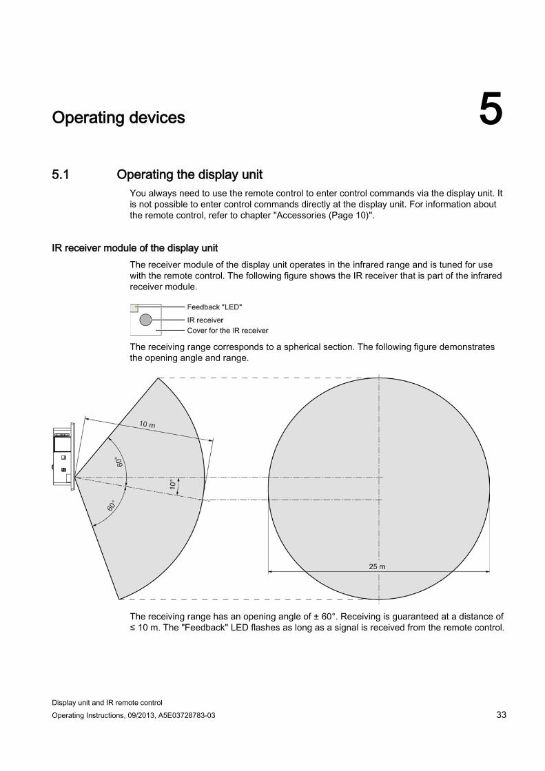
IR receiver module of the display unit The receiver module of the display unit operates in the infrared range and is tuned for use with the remote control. The following figure shows the IR receiver that is part of the infrared receiver module.
The receiving range corresponds to a spherical section. The following figure demonstrates the opening angle and range.
The receiving range has an opening angle of ± 60°. Receiving is guaranteed at a distance of ≤ 10 m. The "Feedback" LED flashes as long as a signal is received from the remote control.
Operating devices 5.1 Operating the display unit
Display unit and IR remote control 34 Operating Instructions, 09/2013, A5E03728783-03
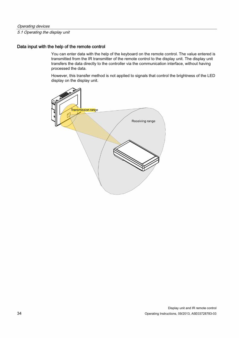
Data input with the help of the remote control You can enter data with the help of the keyboard on the remote control. The value entered is transmitted from the IR transmitter of the remote control to the display unit. The display unit transfers the data directly to the controller via the communication interface, without having processed the data.
However, this transfer method is not applied to signals that control the brightness of the LED display on the display unit.
Operating devices 5.2 Operating the IR remote control
Display unit and IR remote control Operating Instructions, 09/2013, A5E03728783-03 35
5.2 Operating the IR remote control
5.2.1 Inserting and changing batteries
Requirement ● 2 Mignon batteries
The batteries are included in the accessory kit.
Procedure
Note
Be careful not to press any keys while replacing the battery. Such an action may unintentionally trigger a function.
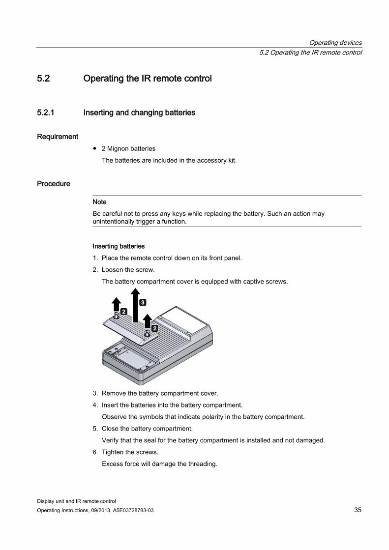
Inserting batteries
1. Place the remote control down on its front panel.
2. Loosen the screw.
The battery compartment cover is equipped with captive screws.
3. Remove the battery compartment cover.
4. Insert the batteries into the battery compartment.
Observe the symbols that indicate polarity in the battery compartment.
5. Close the battery compartment.
Verify that the seal for the battery compartment is installed and not damaged.
6. Tighten the screws.
Excess force will damage the threading.
Operating devices 5.2 Operating the IR remote control
Display unit and IR remote control 36 Operating Instructions, 09/2013, A5E03728783-03
Removing batteries
Remove the batteries in the same way. Make provisions for the proper disposal of waste batteries. Additional information is available in the Preface (Page 39), section "Disposal of batteries".
5.2.2 Checking the battery charge You can test the charging state of the batteries of the remote control.
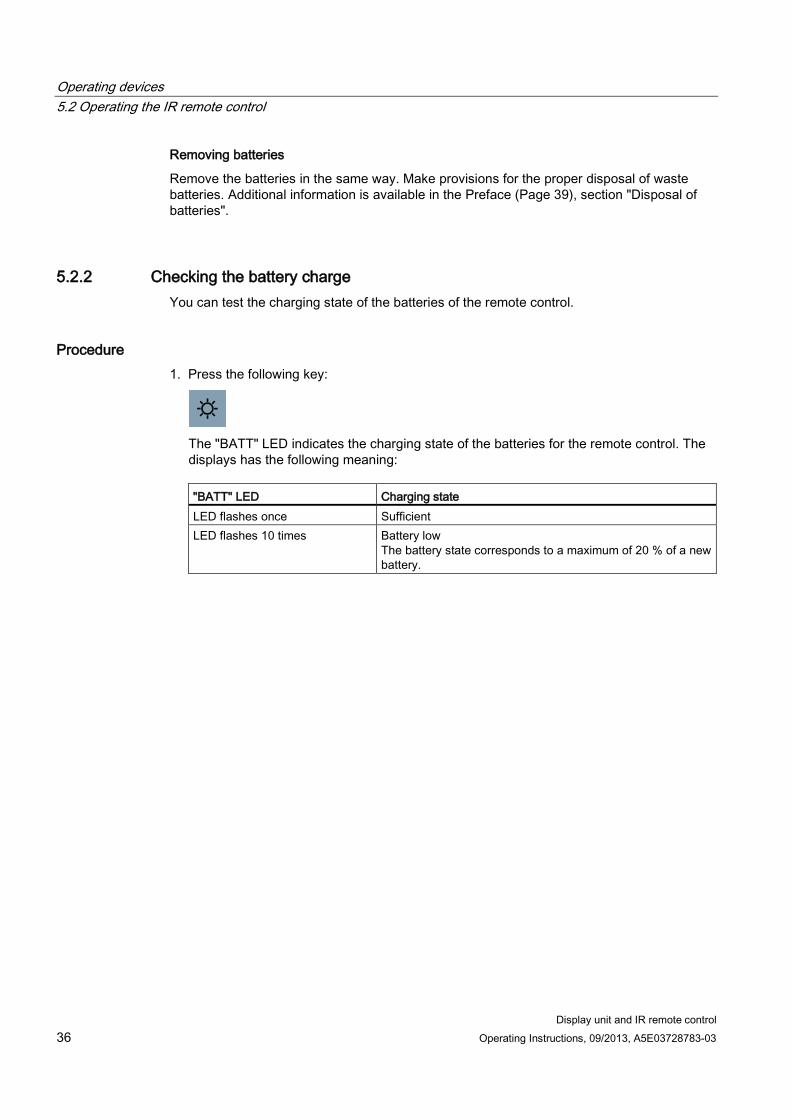
Procedure 1. Press the following key:
The "BATT" LED indicates the charging state of the batteries for the remote control. The displays has the following meaning:
"BATT" LED Charging state LED flashes once Sufficient LED flashes 10 times Battery low
The battery state corresponds to a maximum of 20 % of a new battery.
Operating devices 5.2 Operating the IR remote control
Display unit and IR remote control Operating Instructions, 09/2013, A5E03728783-03 37
5.2.3 Adjusting brightness You can use the remote control to adjust the brightness of the LED display on the display unit. The brightness control signals are only evaluated by the display unit.
These signals do not adjust the brightness of both signal lamps.
For reasons of safety, you cannot adjust the brightness of the LED display on a permanent basis. The adjustment is retained for the duration of 60 seconds. On expiration, the brightness is reset automatically.
However, the brightness is not reset as long as you transmit signals from the remote control to the display unit. The adjustment is retained for the duration of 60 seconds after the last input from the remote control. On expiration, the brightness is reset again.
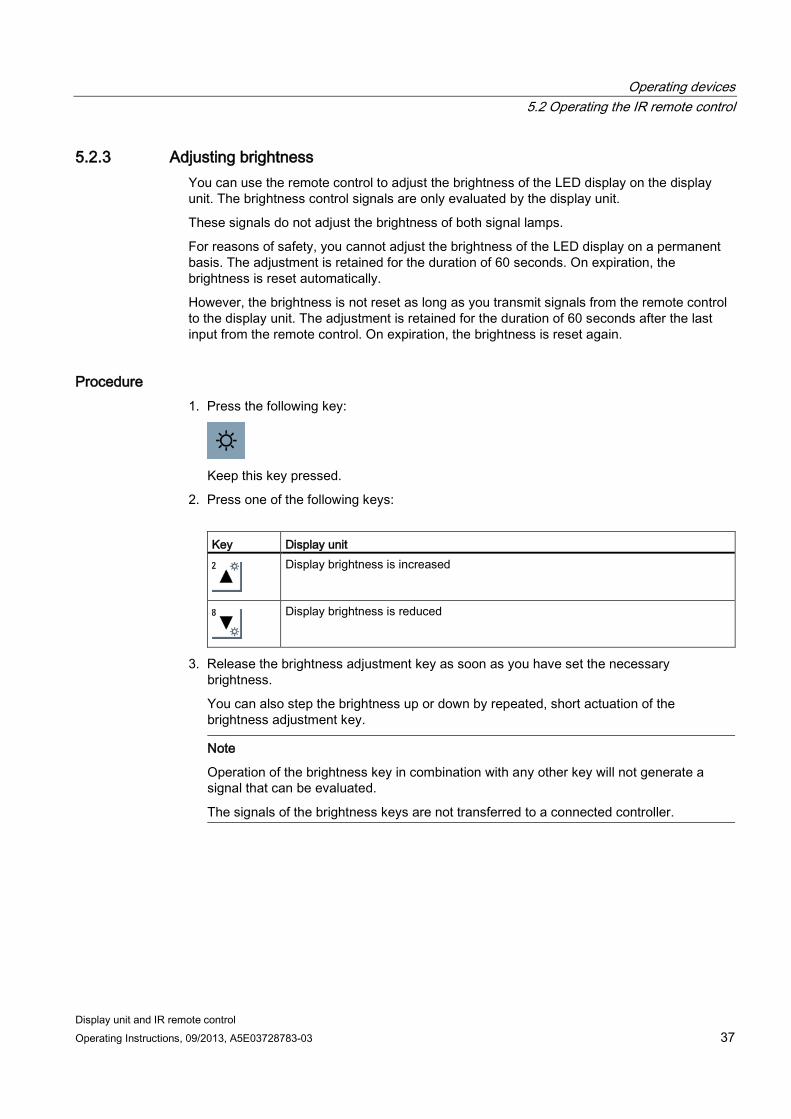
Procedure 1. Press the following key:
Keep this key pressed.
2. Press one of the following keys:
Key Display unit
Display brightness is increased
Display brightness is reduced
3. Release the brightness adjustment key as soon as you have set the necessary brightness.
You can also step the brightness up or down by repeated, short actuation of the brightness adjustment key.
Note
Operation of the brightness key in combination with any other key will not generate a signal that can be evaluated.
The signals of the brightness keys are not transferred to a connected controller.
Operating devices 5.2 Operating the IR remote control
Display unit and IR remote control 38 Operating Instructions, 09/2013, A5E03728783-03
5.2.4 Function principle and functional scope
Function principle The remote control serves as wireless input device for the following devices:
● Display unit
Controls the display brightness.
● EMS400S carrier controller
These are control commands to the carrier controller for moving the EMS carrier.
Functional scope The following operating modes can be configured in STEP 7 for the remote control keys:
Operating mode Number of configurable signals Single operation 15 Double operation 105 Triple operation and more 0 Brightness key, standalone 0 Brightness key with brightness adjustment key
0
The actions triggered by the transmitted signals in the connected controller depend on the project.
Brightness key signals are not transferred to the connected controller by the display unit.
Display unit and IR remote control Operating Instructions, 09/2013, A5E03728783-03 39
Maintenance and repairs 6
Maintenance The display unit and remote control on maintenance-free. Cyclic maintenance work is not required. However, you should not dispense with cleaning of the device.
Clean the front of the device if soiled, or if legibility of the LED display is impaired.
NOTICE
Risk of damage
The use of compressed air, steam blasters, or aggressive solutions or cleaners will damage the device.
Use a cleaning cloth that is moistened with a cleaning agent to clean the equipment. Only use water with a little liquid soap or a screen cleaning foam.
Repairs The display unit will not be repaired. You can return the faulty designs for the purpose of fault analysis to the Retouren-Center Fürth .
The address is:
Siemens AG Sektor Industry Retouren-Center Siemensstr. 2 90766 Fürth Germany
You will receive a credit note for the return device. A credit not is only granted if the party that submitted the device has ordered a new device.
Recycling and disposal The products described in this manual can be recycled due to their low level of contaminants. Contact a certified disposal service company for environmentally sound recycling and disposal of your old devices.
Maintenance and repairs
Display unit and IR remote control 40 Operating Instructions, 09/2013, A5E03728783-03
Disposal of batteries and rechargeable batteries Waste batteries and rechargeable batteries are hazardous waste the may not be disposed of in residual waste. For this reason, dispose of waste batteries and rechargeable batteries properly and in compliance with valid guidelines. Identify the container provided for this purpose with the label, "Used batteries and rechargeables".
Note
You can deposit used batteries and rechargeables at any public collection site and anywhere batteries or rechargeables of similar type are sold.
You can also send batteries and rechargeables to the following address:
Siemens AG Sektor Industry Retouren-Center Siemensstr. 2 90766 Fürth Germany
Display unit and IR remote control Operating Instructions, 09/2013, A5E03728783-03 41
Technical specifications 7 7.1 Display unit
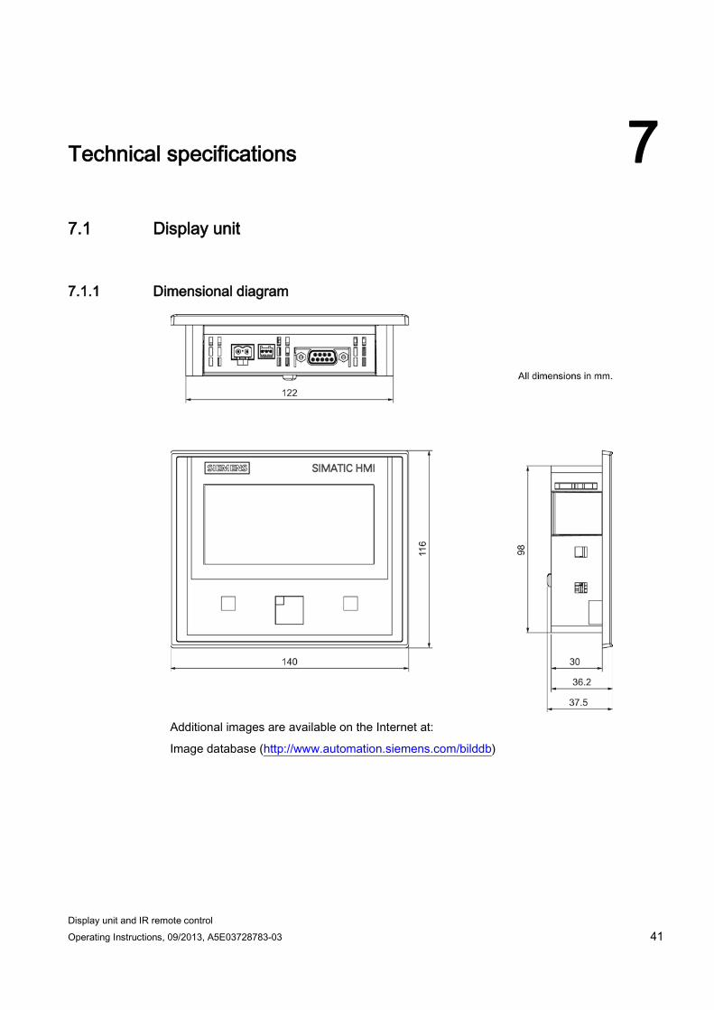
7.1.1 Dimensional diagram
Additional images are available on the Internet at:
Image database (http://www.automation.siemens.com/bilddb)
Technical specifications 7.1 Display unit
Display unit and IR remote control 42 Operating Instructions, 09/2013, A5E03728783-03
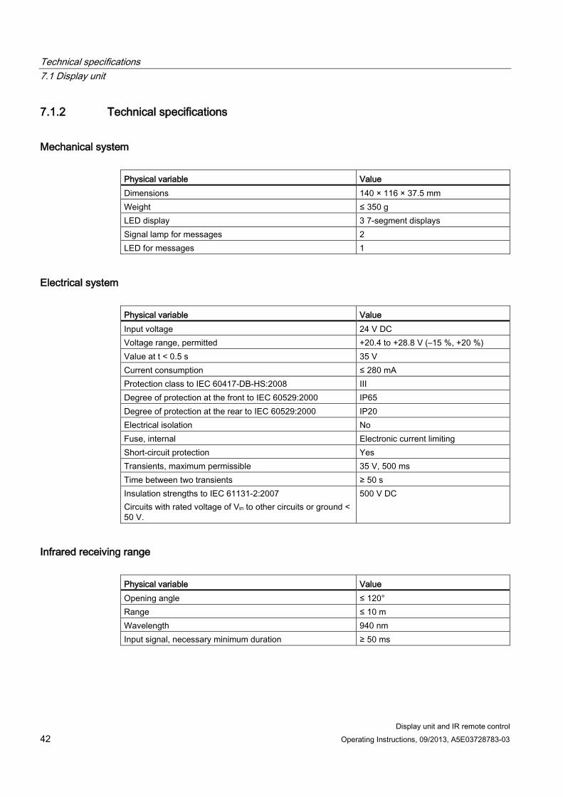
7.1.2 Technical specifications
Mechanical system Physical variable Value Dimensions 140 × 116 × 37.5 mm Weight ≤ 350 g LED display 3 7-segment displays Signal lamp for messages 2 LED for messages 1
Electrical system Physical variable Value Input voltage 24 V DC Voltage range, permitted +20.4 to +28.8 V (–15 %, +20 %) Value at t < 0.5 s 35 V Current consumption ≤ 280 mA Protection class to IEC 60417-DB-HS:2008 III Degree of protection at the front to IEC 60529:2000 IP65 Degree of protection at the rear to IEC 60529:2000 IP20 Electrical isolation No Fuse, internal Electronic current limiting Short-circuit protection Yes Transients, maximum permissible 35 V, 500 ms Time between two transients ≥ 50 s Insulation strengths to IEC 61131-2:2007 Circuits with rated voltage of Vin to other circuits or ground < 50 V.
500 V DC
Infrared receiving range Physical variable Value Opening angle ≤ 120° Range ≤ 10 m Wavelength 940 nm Input signal, necessary minimum duration ≥ 50 ms
Technical specifications 7.1 Display unit
Display unit and IR remote control Operating Instructions, 09/2013, A5E03728783-03 43
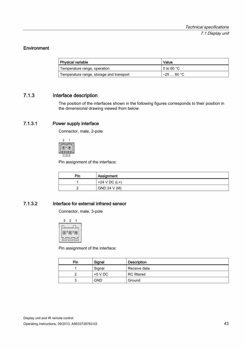
Environment Physical variable Value Temperature range, operation 0 to 60 °C Temperature range, storage and transport –25 … 60 °C
7.1.3 Interface description The position of the interfaces shown in the following figures corresponds to their position in the dimensional drawing viewed from below.
7.1.3.1 Power supply interface Connector, male, 2-pole
Pin assignment of the interface:
Pin Assignment 1 +24 V DC (L+) 2 GND 24 V (M)
7.1.3.2 Interface for external infrared sensor Connector, male, 3-pole
Pin assignment of the interface:
Pin Signal Description 1 Signal Receive data 2 +5 V DC RC filtered 3 GND Ground
Technical specifications 7.1 Display unit
Display unit and IR remote control 44 Operating Instructions, 09/2013, A5E03728783-03
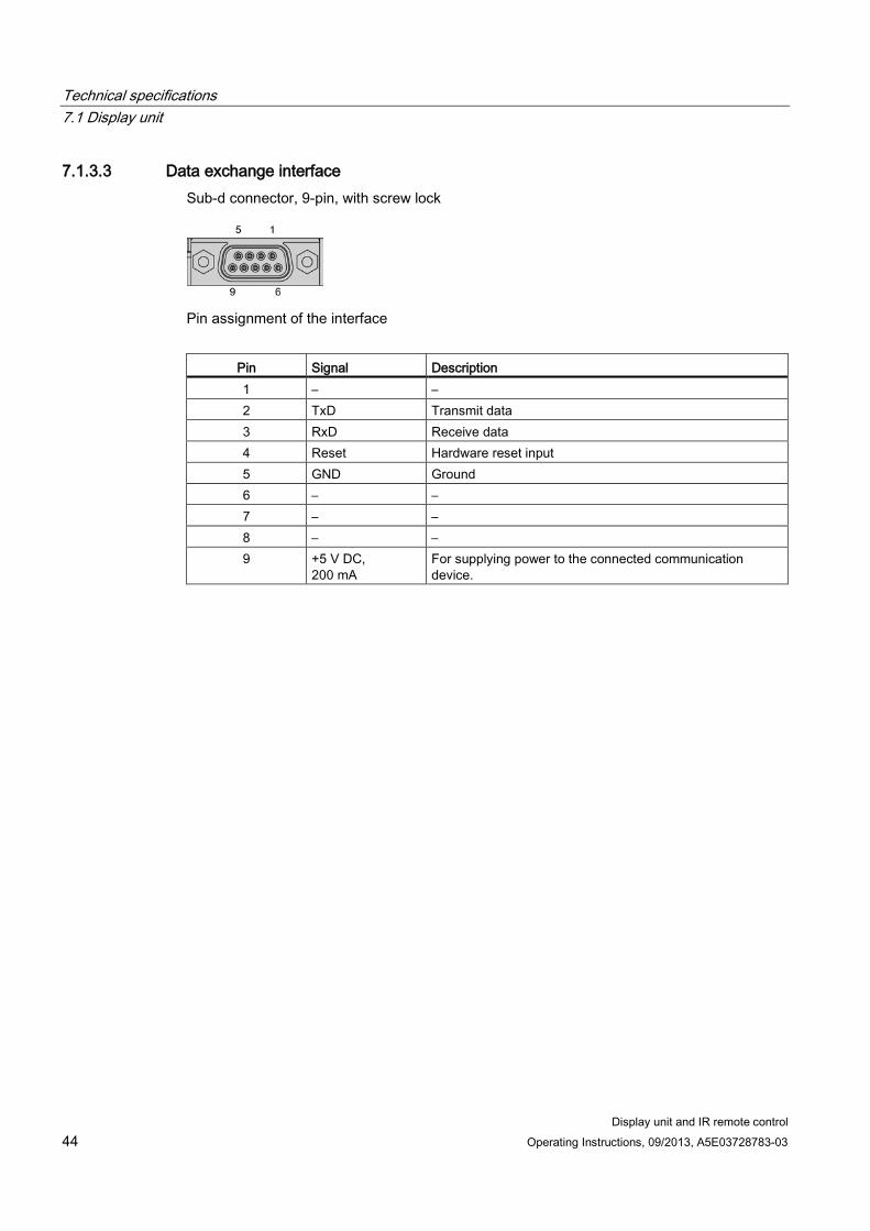
7.1.3.3 Data exchange interface Sub-d connector, 9-pin, with screw lock
Pin assignment of the interface
Pin Signal Description 1 – – 2 TxD Transmit data 3 RxD Receive data 4 Reset Hardware reset input 5 GND Ground 6 – – 7 – – 8 – – 9 +5 V DC,
200 mA For supplying power to the connected communication device.
Technical specifications 7.2 IR remote control
Display unit and IR remote control Operating Instructions, 09/2013, A5E03728783-03 45
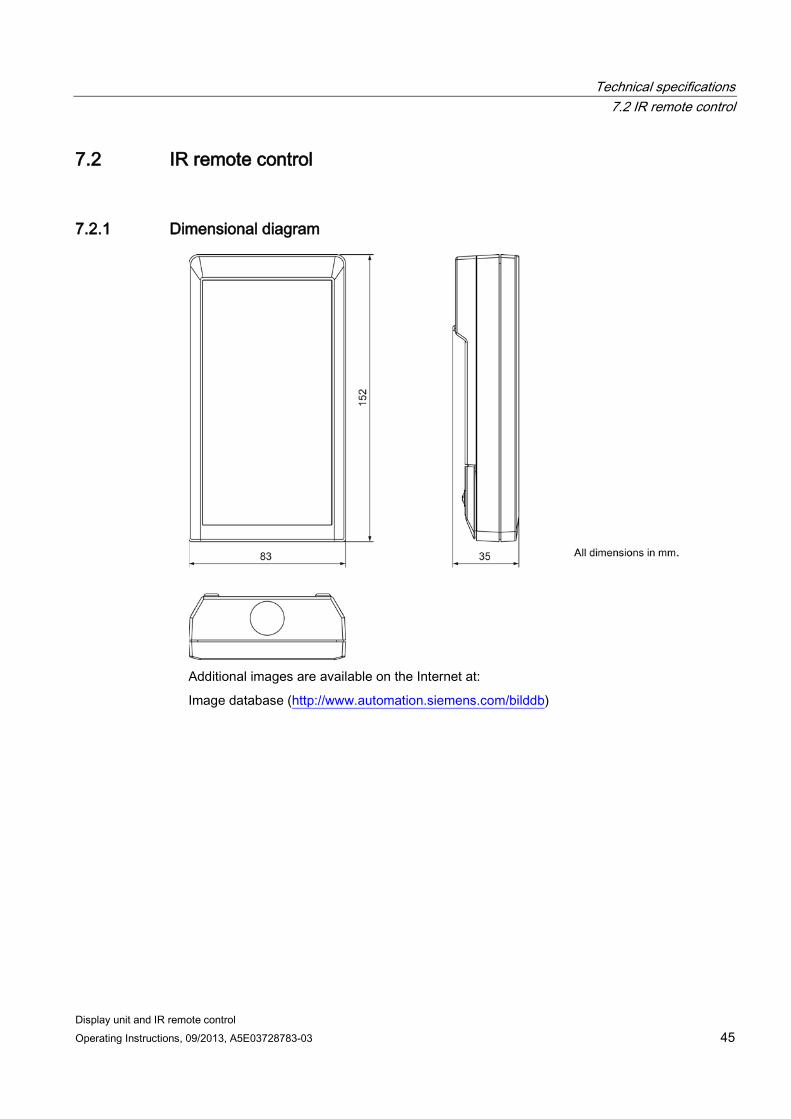
7.2 IR remote control
7.2.1 Dimensional diagram
Additional images are available on the Internet at:
Image database (http://www.automation.siemens.com/bilddb)
Technical specifications 7.2 IR remote control
Display unit and IR remote control 46 Operating Instructions, 09/2013, A5E03728783-03
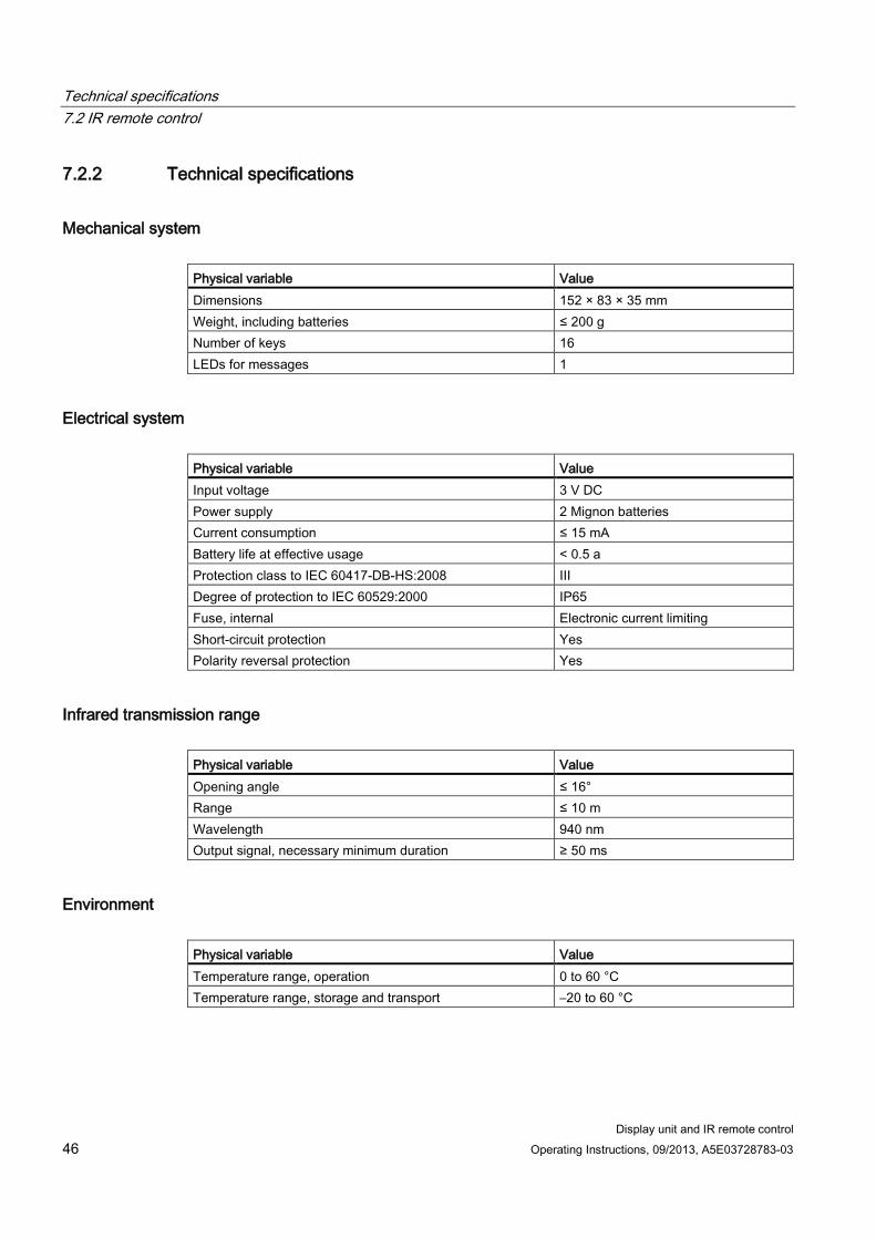
7.2.2 Technical specifications
Mechanical system Physical variable Value Dimensions 152 × 83 × 35 mm Weight, including batteries ≤ 200 g Number of keys 16 LEDs for messages 1
Electrical system Physical variable Value Input voltage 3 V DC Power supply 2 Mignon batteries Current consumption ≤ 15 mA Battery life at effective usage < 0.5 a Protection class to IEC 60417-DB-HS:2008 III Degree of protection to IEC 60529:2000 IP65 Fuse, internal Electronic current limiting Short-circuit protection Yes Polarity reversal protection Yes
Infrared transmission range Physical variable Value Opening angle ≤ 16° Range ≤ 10 m Wavelength 940 nm Output signal, necessary minimum duration ≥ 50 ms
Environment Physical variable Value Temperature range, operation 0 to 60 °C Temperature range, storage and transport –20 to 60 °C
Technical specifications 7.3 Approvals
Display unit and IR remote control Operating Instructions, 09/2013, A5E03728783-03 47
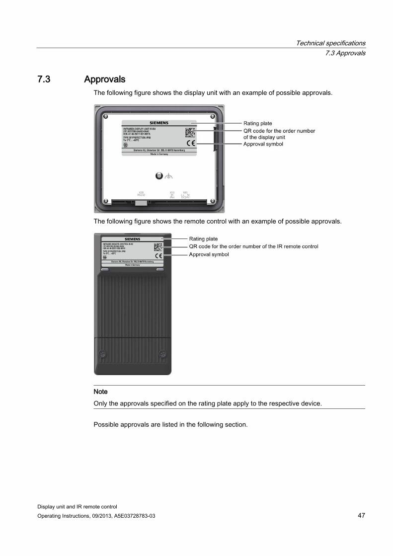
7.3 Approvals The following figure shows the display unit with an example of possible approvals.
The following figure shows the remote control with an example of possible approvals.
Note
Only the approvals specified on the rating plate apply to the respective device.
Possible approvals are listed in the following section.
Technical specifications 7.4 Notes about usage
Display unit and IR remote control 48 Operating Instructions, 09/2013, A5E03728783-03
CE approval The device complies with European standards for programmable logic controllers which were published in the Official Journals of the European Union:
● 2004/108/EC "Electromagnetic Compatibility" (EMC Directive)
● 1999/5/ECG "Directive of the European Parliament and of the Council from March 9, 1999 relating to Radio Equipment and Telecommunications Terminal Equipment and the Mutual Recognition of their Conformity"
● Specific absorption rate in accordance with EN 50932:2004
EC Declaration of Conformity The EC Declarations of Conformity are available to the relevant authorities at the following address:
Siemens AG Sektor Industry I IA AS RD ST Postfach 1963 92209 Amberg Germany
UL approval Note the following:
The device shall be supplied from an insulating source, rated 24 VDC (class 2).
"Underwriters Laboratories Inc." approval in accordance with UL 508 (Industrial Control Equipment)
Note
The UL symbol indicates that the display unit and the IR remote control have been tested and approved by Underwriters Laboratories according to standard UL 508.
7.4 Notes about usage
Industrial applications The display unit and IR remote control are designed for industrial applications. For this reason, the following standards are met:
Standard Title Release EN 61131-2:2007 Programmable logic controllers – Part 2:
Equipment requirements and tests 01.01.2009
Use in residential areas Rules for operation in residential areas:
The display unit and IR remote control meet requirements of limit class B to EN 55011 in terms of the emission of RF interference.
Technical specifications 7.5 Electromagnetic compatibility
Display unit and IR remote control Operating Instructions, 09/2013, A5E03728783-03 49
7.5 Electromagnetic compatibility The device also meets requirements of the EMC legislation on internal European market. The enhanced testing and limit value levels defined by CDV 61326-3-1/Ed. 1 have been taken into account during the type test.
The EMC test of the device was passed in accordance with the following standards:
Standard Title Release EN 61000-6-2:2006 EMC: Basic technical standard – Immunity to
interference in industrial areas 01.05.2006
EN 61000-6-4:2007 EMC: Basic technical standard – Immunity to interference emission in industrial areas
01.11.2007
EMC-compliant installation The EMC compliant installation of the device and the use of interference proof cables form the basics for error-free operation.
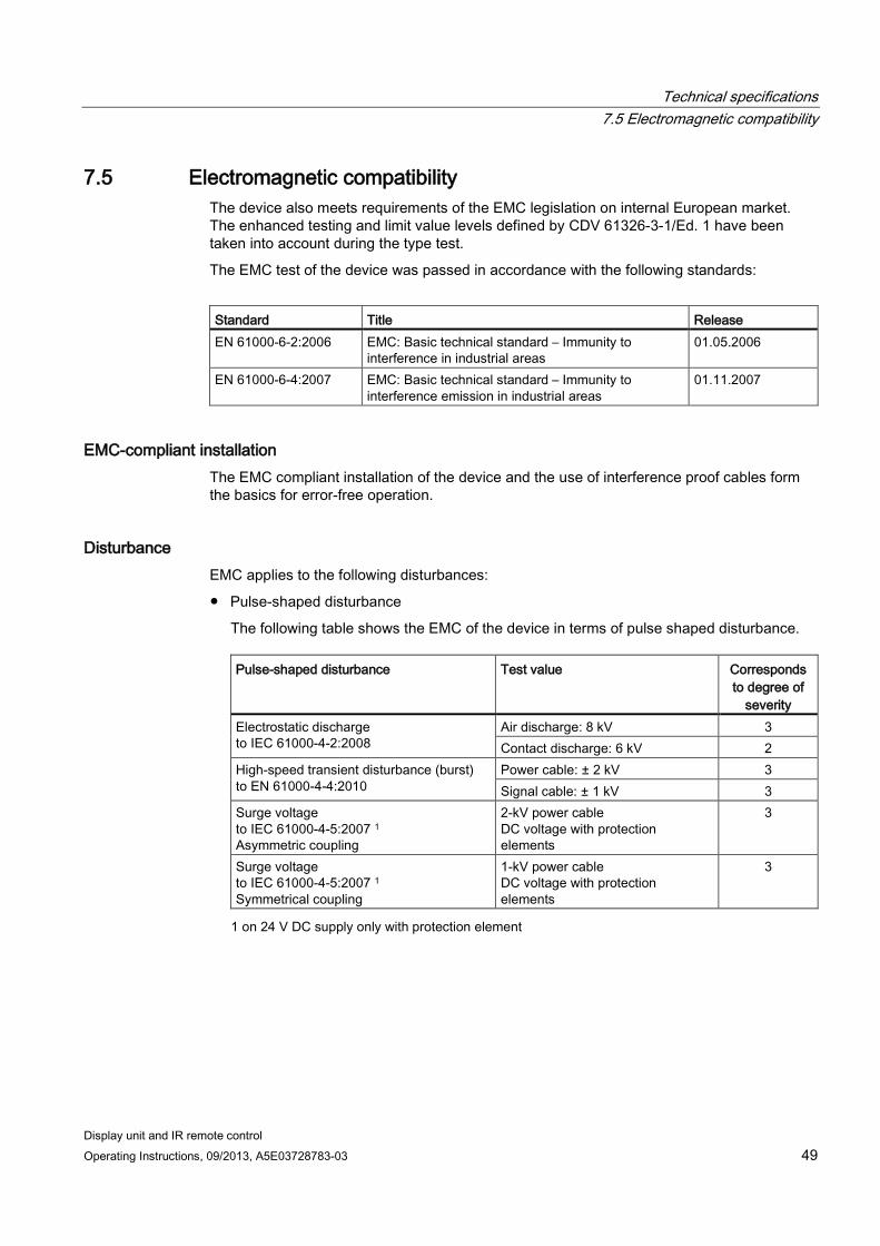
Disturbance EMC applies to the following disturbances:
● Pulse-shaped disturbance
The following table shows the EMC of the device in terms of pulse shaped disturbance.
Pulse-shaped disturbance Test value Corresponds to degree of
severity Electrostatic discharge to IEC 61000-4-2:2008
Air discharge: 8 kV 3 Contact discharge: 6 kV 2
High-speed transient disturbance (burst) to EN 61000-4-4:2010
Power cable: ± 2 kV 3 Signal cable: ± 1 kV 3
Surge voltage to IEC 61000-4-5:2007 1 Asymmetric coupling
2-kV power cable DC voltage with protection elements
3
Surge voltage to IEC 61000-4-5:2007 1 Symmetrical coupling
1-kV power cable DC voltage with protection elements
3
1 on 24 V DC supply only with protection element
Technical specifications 7.5 Electromagnetic compatibility
Display unit and IR remote control 50 Operating Instructions, 09/2013, A5E03728783-03
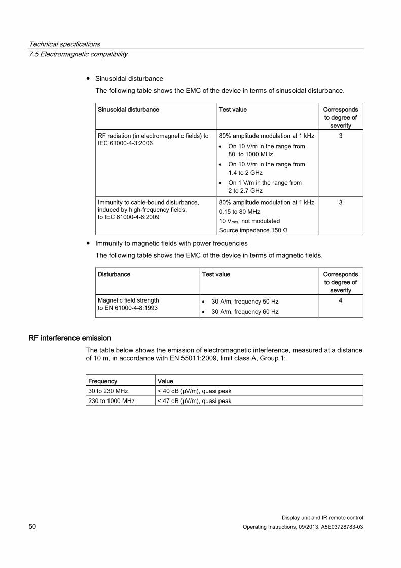
● Sinusoidal disturbance
The following table shows the EMC of the device in terms of sinusoidal disturbance.
Sinusoidal disturbance Test value Corresponds to degree of
severity RF radiation (in electromagnetic fields) to IEC 61000-4-3:2006
80% amplitude modulation at 1 kHz • On 10 V/m in the range from
80 to 1000 MHz • On 10 V/m in the range from
1.4 to 2 GHz • On 1 V/m in the range from
2 to 2.7 GHz
3
Immunity to cable-bound disturbance, induced by high-frequency fields, to IEC 61000-4-6:2009
80% amplitude modulation at 1 kHz 0.15 to 80 MHz 10 Vrms, not modulated Source impedance 150 Ω
3
● Immunity to magnetic fields with power frequencies
The following table shows the EMC of the device in terms of magnetic fields.
Disturbance Test value Corresponds to degree of
severity Magnetic field strength to EN 61000-4-8:1993
• 30 A/m, frequency 50 Hz • 30 A/m, frequency 60 Hz
4
RF interference emission The table below shows the emission of electromagnetic interference, measured at a distance of 10 m, in accordance with EN 55011:2009, limit class A, Group 1:
Frequency Value 30 to 230 MHz < 40 dB (μV/m), quasi peak 230 to 1000 MHz < 47 dB (μV/m), quasi peak
Technical specifications 7.6 Environmental conditions
Display unit and IR remote control Operating Instructions, 09/2013, A5E03728783-03 51
7.6 Environmental conditions
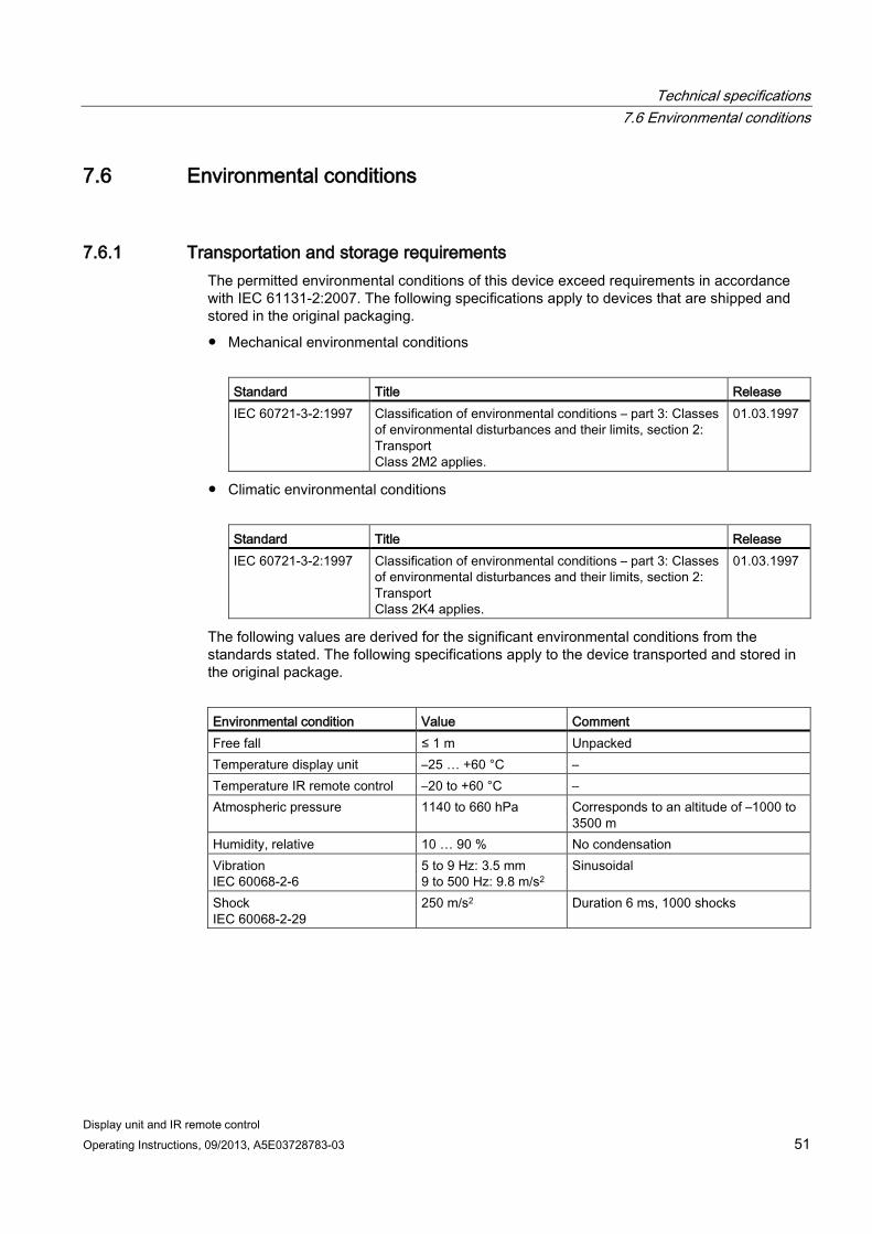
7.6.1 Transportation and storage requirements The permitted environmental conditions of this device exceed requirements in accordance with IEC 61131-2:2007. The following specifications apply to devices that are shipped and stored in the original packaging.
● Mechanical environmental conditions
Standard Title Release IEC 60721-3-2:1997 Classification of environmental conditions – part 3: Classes
of environmental disturbances and their limits, section 2: Transport Class 2M2 applies.
01.03.1997
● Climatic environmental conditions
Standard Title Release IEC 60721-3-2:1997 Classification of environmental conditions – part 3: Classes
of environmental disturbances and their limits, section 2: Transport Class 2K4 applies.
01.03.1997
The following values are derived for the significant environmental conditions from the standards stated. The following specifications apply to the device transported and stored in the original package.
Environmental condition Value Comment Free fall ≤ 1 m Unpacked Temperature display unit –25 … +60 °C – Temperature IR remote control –20 to +60 °C – Atmospheric pressure 1140 to 660 hPa Corresponds to an altitude of –1000 to
3500 m Humidity, relative 10 … 90 % No condensation Vibration IEC 60068-2-6
5 to 9 Hz: 3.5 mm 9 to 500 Hz: 9.8 m/s2
Sinusoidal
Shock IEC 60068-2-29
250 m/s2 Duration 6 ms, 1000 shocks
Technical specifications 7.6 Environmental conditions
Display unit and IR remote control 52 Operating Instructions, 09/2013, A5E03728783-03
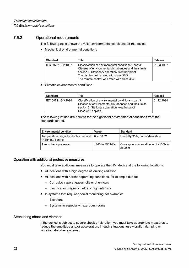
7.6.2 Operational requirements The following table shows the valid environmental conditions for the device.
● Mechanical environmental conditions
Standard Title Release IEC 60721-3-2:1997 Classification of environmental conditions – part 3:
Classes of environmental disturbances and their limits, section 3: Stationary operation, weather-proof The display unit is rated with class 3M3. The remote control was rated with class 3K7.
01.03.1997
● Climatic environmental conditions
Standard Title Release IEC 60721-3-3:1994 Classification of environmental conditions – part 3:
Classes of environmental disturbances and their limits, section 3: Stationary operation, weatherproof Class 3K3 applies.
01.12.1994
The following values are derived for the significant environmental conditions from the standards stated.
Environmental condition Value Standard Temperature range for display unit and IR remote control
0 to 60 °C Humidity 95%, no condensation
Atmospheric pressure 1140 to 795 hPa Corresponds to an altitude of –1000 to 2500 m
Operation with additional protective measures You must take additional measures to operate the HMI device at the following locations:
● At locations with a high degree of ionizing radiation
● At locations with harsher operating conditions, for example due to:
– Corrosive vapors, gases, oils or chemicals
– Electrical or magnetic fields of high intensity
● In systems that require special monitoring, for example:
– Elevators
– Systems in especially hazardous rooms
Attenuating shock and vibration If the device is subject to severe shock or vibration, you must take appropriate measures to reduce the amplitude and/or acceleration. In such situations, use vibration damping or vibration absorber systems.
Technical specifications 7.6 Environmental conditions
Display unit and IR remote control Operating Instructions, 09/2013, A5E03728783-03 53
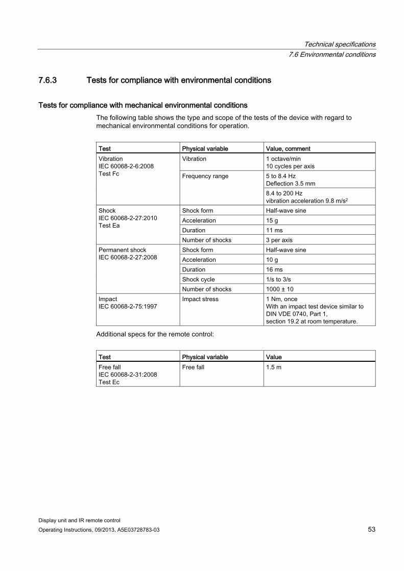
7.6.3 Tests for compliance with environmental conditions
Tests for compliance with mechanical environmental conditions The following table shows the type and scope of the tests of the device with regard to mechanical environmental conditions for operation.
Test Physical variable Value, comment Vibration IEC 60068-2-6:2008 Test Fc
Vibration 1 octave/min 10 cycles per axis
Frequency range 5 to 8.4 Hz Deflection 3.5 mm 8.4 to 200 Hz vibration acceleration 9.8 m/s2
Shock IEC 60068-2-27:2010 Test Ea
Shock form Half-wave sine Acceleration 15 g Duration 11 ms Number of shocks 3 per axis
Permanent shock IEC 60068-2-27:2008
Shock form Half-wave sine Acceleration 10 g Duration 16 ms Shock cycle 1/s to 3/s Number of shocks 1000 ± 10
Impact IEC 60068-2-75:1997
Impact stress 1 Nm, once With an impact test device similar to DIN VDE 0740, Part 1, section 19.2 at room temperature.
Additional specs for the remote control:
Test Physical variable Value Free fall IEC 60068-2-31:2008 Test Ec
Free fall 1.5 m
Technical specifications 7.6 Environmental conditions
Display unit and IR remote control 54 Operating Instructions, 09/2013, A5E03728783-03
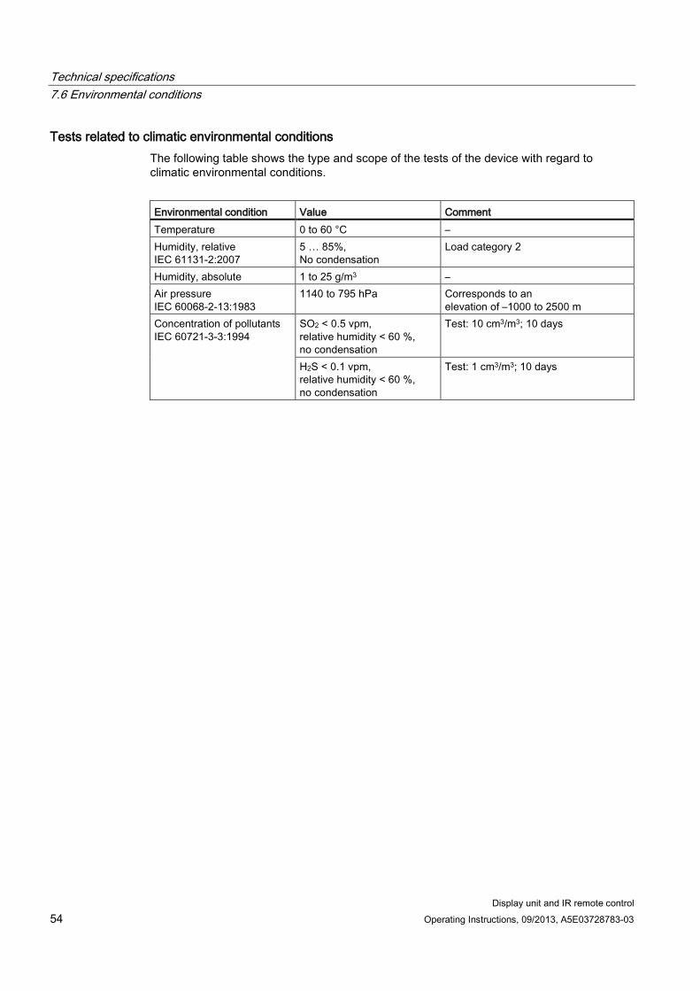
Tests related to climatic environmental conditions The following table shows the type and scope of the tests of the device with regard to climatic environmental conditions.
Environmental condition Value Comment Temperature 0 to 60 °C – Humidity, relative IEC 61131-2:2007
5 … 85%, No condensation
Load category 2
Humidity, absolute 1 to 25 g/m3 – Air pressure IEC 60068-2-13:1983
1140 to 795 hPa Corresponds to an elevation of –1000 to 2500 m
Concentration of pollutants IEC 60721-3-3:1994
SO2 < 0.5 vpm, relative humidity < 60 %, no condensation
Test: 10 cm3/m3; 10 days
H2S < 0.1 vpm, relative humidity < 60 %, no condensation
Test: 1 cm3/m3; 10 days
Display unit and IR remote control Operating Instructions, 09/2013, A5E03728783-03 55
Appendix A A.1 Technical support
Technical support for the devices described in this document is available at:
● Technical Support (http://www.siemens.de/automation/csi_en_WW)
● Support Request (http://www.siemens.com/automation/support-request)
● Service (http://support.automation.siemens.com/WW/view/en/16604318)
● Contacts and office locations (http://www.automation.siemens.com/mcms/aspa-db/en/Pages/default.aspx)
● Training center (http://sitrain.automation.siemens.com/sitrainworld/?AppLang=en)
SIMATIC product information is available at:
● Industry Portal (http://www.automation.siemens.com/_en/portal/index.htm)
● Overall SIMATIC documentation (http://www.siemens.com/simatic-tech-doku-portal)
Appendix A.2 Abbreviations
Display unit and IR remote control 56 Operating Instructions, 09/2013, A5E03728783-03
A.2 Abbreviations AC Alternating current AG Aktiengesellschaft DC Direct Current DIN Deutsches Institut für Normung EC Europäische Gemeinschaft ESD Components and modules endangered by electrostatic discharge EMS Electrical Monorail System EMS400S Electric Monorail System 400 Signal EMC Electromagnetic compatibility EN European standard GND Ground HF High Frequency IEC International Electronic Commission IP Ingress Protection IR Infrared IT Information Technology LED Light Emitting Diode PELV Protective Extra Low Voltage PI Produktinformation RxD Receive Data Sub-D Subminiature D TxD Transmit Data VDE Verband der Elektrotechnik, Elektronik und Informationstechnik e. V.
Display unit and IR remote control Operating Instructions, 09/2013, A5E03728783-03 57
Index
A Approval
CE, 48
B Batteries
Inserting, 35 Removing, 36
Battery Used, 40
C Cable
Connecting, 23 CE approval, 48 Clamping bracket, 21 Clearance
Display unit, 19 Condensation, 23 Connecting
Mains terminal block, 27 Power supply, 27 Sensor, 28
Contact person, 55 Control element, 31 Cursor key, 32
D Data transmission, 23 Declaration of Conformity, 48 Device failure, 23 Display element, 31 Display unit, 11, 33, 37, 37
Clearance, 19 Layout, 29 Mounting, 21 Mounting location, 19 Mounting position, 17
Disposal, 39 Document
SIMATIC complete, 55
E EC Declaration of Conformity, 48 Electrical system
Technical specifications, 42, 46 Enter key, 32 Environment
Technical specifications, 43, 46 Environmental condition, 51, 52 ESD, 14
F Function key, 31 Function principle, 38 Functional scope, 38
I Industry Portal, 55 Infrared transmission range
Technical specifications, 42, 46 Interfaces, 24 IR receiver module, 33 IT Security, 15
L LED display, 37
M Mechanical system
Technical specifications, 42, 46 Mounting
Display unit, 21 Mounting cut-out
Dimensions, 20 Properties, 20
Mounting location Display unit, 19
Mounting mode, 21 Mounting position
Display unit, 17
Index
Display unit and IR remote control 58 Operating Instructions, 09/2013, A5E03728783-03
O Office location, 55 Operating instructions
Associated documents, 3 Purpose, 3 Scope, 4
Operation Mobile, 18
P PELV, 27 Pin assignment
Power supply, 43 Sensor, 43
Potential difference, 24 Power supply, 24
R Rating plate, 48 Receiver module, 33 Rechargeable battery
Used, 40 Recycling, 39
S Scope
Operating instructions, 4 Scope of delivery, 10, 11
Checking, 17, 30 Security information, 15 Sensor
Connecting, 28 Service, 55 Signal combination, 38 Support
Technical, 55 Support request, 55
T Technical specifications
Power supply, 43 Sensor, 43
Technical support, 55 Technical Support, 55 Training center, 55 Transport damage, 17, 30
W Wiring
Cable, 23 Sequence, 23
Wiring sequence, 23