Embed Size (px)
Citation preview
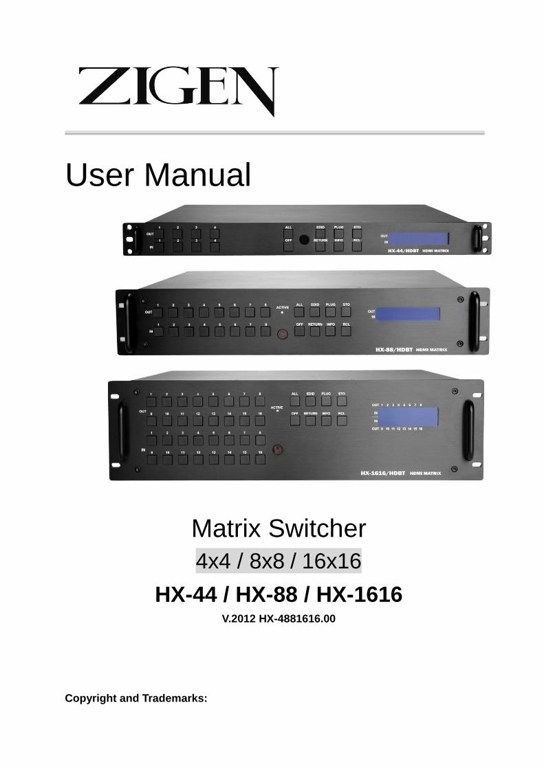
Matrix Switching System—User Manual
User Manual
Matrix Switcher
4x4 / 8x8 / 16x16
HX-44 / HX-88 / HX-1616 V.2012 HX-4881616.00
Copyright and Trademarks:

Matrix Switcher Series—User Manual
1
All rights reserved by ZIGEN, INC. No part of this document may be reproduced in any form or by any means without written permission from the product manufacturer. Changes are periodically made to the information in this document. They will be incorporated in subsequent editions. The product manufacturer may make improvements and /or changes in the product described in this document at any time.
All the registered trademarks referred to this manual are belonging to their respective companies.
Before You Begin
Follow all instructions marked on the device during using.
Do not attempt to maintain the device by yourself, any faults, please contact your vendor.
Provide proper ventilation and air circulation and do not use near water.
It is better to keep it in a dry environment.
The system should be installed indoor only. Install either on a sturdy rack or desk in a well-ventilated place.
Only use the power cord supported with the device.
Do not use liquid or aerosol cleaners to clean the device.
Always unplug the power to the device before cleaning.
Unplug the power cord during lightning or after a prolonged period of non-use to avoid damage to the equipment.
Matrix Switcher Series—User Manual
2
Table of Contents 1. Matrix System Overview ............................................................................................................ 4
1.1 Introduction ....................................................................................................................... 4
1.2 Packing .............................................................................................................................. 5
1.3 Accessories (Optional) ...................................................................................................... 6
2. Features ....................................................................................................................................... 6
3. Specifications .............................................................................................................................. 8
4. Device Installation ....................................................................................................................... 9
5. Front/Rear Panels ...................................................................................................................... 10
5.1 Front Panel ...................................................................................................................... 10
5.2 Rear Panel ....................................................................................................................... 13
6. Matrix Switcher and Peripherals Connections .......................................................................... 15
6.1 Input/Output Connections ............................................................................................... 18
6.1.1 Output LED .......................................................................................................... 19
6.1.2 Output Cable ........................................................................................................ 19
6.2 IR Pass-through Connection ............................................................................................ 20
6.3 IR EXT Connection ......................................................................................................... 21
6.4 Power Connection ........................................................................................................... 21
6.5 Matrix Switcher Remote Control .................................................................................... 22
6.6 Ports and Switchers ......................................................................................................... 23
6.6.1 RS-232 .................................................................................................................. 23
6.6.2 RS-485 .................................................................................................................. 25
6.6.3 LAN Port .............................................................................................................. 27
6.6.4 DIP Switcher 8 Pins ............................................................................................. 28
6.6.5 DIP Switcher 2 Pins ............................................................................................. 28
6.6.6 Device ID Settings ............................................................................................... 29
7. Matrix Application Software ..................................................................................................... 31
7.1 Software Introduction ...................................................................................................... 31
7.1.1 Software Description ............................................................................................ 31
7.1.2 Software Activation .............................................................................................. 31
7.1.3 Connect Matrix Switcher and PC ......................................................................... 32
7.2 Matrix Configuration ....................................................................................................... 32
7.2.1 Main Operation Interface ..................................................................................... 34
7.2.2 Disconnect Function Key ..................................................................................... 36
7.2.3 Audio Configuration Function ............................................................................. 38
7.2.4 EDID Configuration Function .............................................................................. 41
7.2.5 RS-232 Memory Function .................................................................................... 42
7.2.6 Options Function .................................................................................................. 43
7.2.7 Other Application ................................................................................................. 43

Matrix Switcher Series—User Manual
3
7.2.8 Communication Protocol/Control Command Code ............................................. 44
7.3 LAN Web Configuration ................................................................................................. 45
7.3.1 Audio Configuration ............................................................................................. 46
7.3.2 Video Configuration ............................................................................................. 47
7.3.3 Device Status Information .................................................................................... 48
7.3.4 Device Output View ............................................................................................. 48
7.3.5 LAN Main Operation ........................................................................................... 49
7.3.6 LAN Memory Function ........................................................................................ 50
7.3.7 LAN IP Function .................................................................................................. 51
7.3.8 Other Application ................................................................................................. 52
8. Operation Examples .................................................................................................................. 53
9. Troubleshooting ......................................................................................................................... 62
Appendix A Matrix Switcher Remote Controller .......................................................................... 64
Appendix B IR Mini-Controller .................................................................................................... 65
Appendix C Firmware Upgrade .................................................................................................... 66
Appendix D RS-232 Communication Protocol ............................................................................. 69
D-1 Host Request .................................................................................................................. 69
D-1.1 Device Byte ......................................................................................................... 69
D-1.2 Request Byte ....................................................................................................... 70
D-1.3 Index Byte ........................................................................................................... 72
D-1.4 Value Byte ........................................................................................................... 73
D-1.5 CRC Byte ............................................................................................................ 74
D-2 Device ACK Packet ....................................................................................................... 75
D-2.1 ACK Type A ........................................................................................................ 75
D-2.2 ACK Type B ........................................................................................................ 76
D-2.3 ACK Type C ........................................................................................................ 77
D-2.4 ACK Type D ........................................................................................................ 78
D-2.5 ACK Type E ........................................................................................................ 79
Appendix E Extender (HX-RW) ................................................................................................... 81
Features ................................................................................................................................. 82
Specifications ........................................................................................................................ 82
Installation ............................................................................................................................. 82
IR Receiver Cable Directions ................................................................................................ 84
IR Blaster Cable Directions ................................................................................................... 84
HDMI Output Connector ...................................................................................................... 84
Wiring Information for Link Connector ................................................................................ 85
Firmware Upgrade ................................................................................................................. 86

Matrix Switching System—User Manual
4
1. Matrix System Overview
1.1 Introduction
ZIGEN HX-44, 88, 1616/HDBT Modular Matrix Routing Switchers are high performance
HDMI matrix switchers designed for applications where routing of high resolution digital
video signals are required. HX-44, 88, 1616/HDBT Matrix switchers are HDMI 1.4b
compatible and supports resolutions up to 4Kx2K/30Hz and HDTV 1080p/60Hz, HX-44,
88, 1616/HDBT also ensures simultaneous distribution of any input source signal to one
or more HDCP compliant displays. (All-to-one / one-to-all combination)
HX-44, 88, 1616/HDBT matrix switchers are ideal for use in bars, restaurants,
commercial, medical, military, government and residential environments where
distribution of high resolution, digital video signals are needed and digital pathway is
essential for maintaining the highest possible image quality from all sources.
HX-44, 88, 1616/HDBT also offers the ability to save (4 for HX-44/HDBT) 8 frequently
used I/O configurations as presets.
HX-44, 88, 1616/HDBT can be operated via the front panel, RS-232, IR or Ethernet.
Figure 1-1 HX-44 Matrix Switcher
Figure 1-2 HX-88 Matrix Switchers
Matrix Switcher Series—User Manual
5
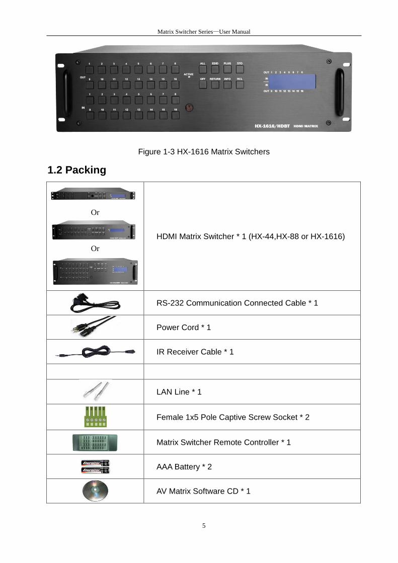
Figure 1-3 HX-1616 Matrix Switchers
1.2 Packing
Or
Or
HDMI Matrix Switcher * 1 (HX-44,HX-88 or HX-1616)
RS-232 Communication Connected Cable * 1
Power Cord * 1
IR Receiver Cable * 1
LAN Line * 1
Female 1x5 Pole Captive Screw Socket * 2
Matrix Switcher Remote Controller * 1
AAA Battery * 2
AV Matrix Software CD * 1
Matrix Switcher Series—User Manual
6
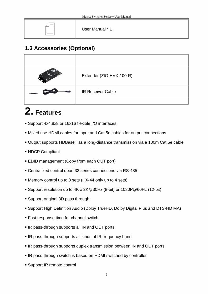
User Manual * 1
1.3 Accessories (Optional)
Extender (ZIG-HVX-100-R)
IR Receiver Cable
2. Features
Support 4x4,8x8 or 16x16 flexible I/O interfaces
Mixed use HDMI cables for input and Cat.5e cables for output connections
Output supports HDBaseT as a long-distance transmission via a 100m Cat.5e cable
HDCP Compliant
EDID management (Copy from each OUT port)
Centralized control upon 32 series connections via RS-485
Memory control up to 8 sets (HX-44 only up to 4 sets)
Support resolution up to 4K x 2K@30Hz (8-bit) or 1080P@60Hz (12-bit)
Support original 3D pass through
Support High Definition Audio (Dolby TrueHD, Dolby Digital Plus and DTS-HD MA)
Fast response time for channel switch
IR pass-through supports all IN and OUT ports
IR pass-through supports all kinds of IR frequency band
IR pass-through supports duplex transmission between IN and OUT ports
IR pass-through switch is based on HDMI switched by controller
Support IR remote control

Matrix Switcher Series—User Manual
7
Support IR Mini-Controller to select the input channel through Output configuration
Support RS-232 control
Support RS-485 serial control
Support Ethernet control
Internal universal power supply
1U rack for HX-44 and 2U rack for HX-88 and 3U rack for HX-1616
Matrix Switcher Series—User Manual
8
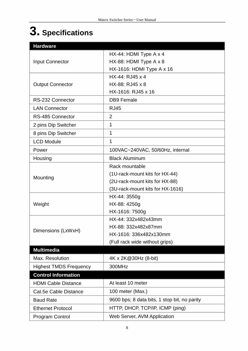
3. Specifications
Hardware
Input Connector
HX-44: HDMI Type A x 4
HX-88: HDMI Type A x 8
HX-1616: HDMI Type A x 16
Output Connector
HX-44: RJ45 x 4
HX-88: RJ45 x 8
HX-1616: RJ45 x 16
RS-232 Connector DB9 Female
LAN Connector RJ45
RS-485 Connector 2
2 pins Dip Switcher 1
8 pins Dip Switcher 1
LCD Module 1
Power 100VAC~240VAC, 50/60Hz, internal
Housing Black Aluminum
Mounting
Rack mountable
(1U-rack-mount kits for HX-44)
(2U-rack-mount kits for HX-88)
(3U-rack-mount kits for HX-1616)
Weight
HX-44: 3550g
HX-88: 4250g
HX-1616: 7500g
Dimensions (LxWxH)
HX-44: 332x482x43mm
HX-88: 332x482x87mm
HX-1616: 336x482x130mm
(Full rack wide without grips)
Multimedia
Max. Resolution 4K x 2K@30Hz (8-bit)
Highest TMDS Frequency 300MHz
Control Information
HDMI Cable Distance At least 10 meter
Cat.5e Cable Distance 100 meter (Max.)
Baud Rate 9600 bps; 8 data bits, 1 stop bit, no parity
Ethernet Protocol HTTP, DHCP, TCP/IP, ICMP (ping)
Program Control Web Server, AVM Application

Matrix Switcher Series—User Manual
9
Serial Control Port RS-232: 9 Pin Female D Type Connector
RS-485: 1X5 Pole Captive Screw
Control Sequence Matrix
Remote Control Remote Controller, IR Receiver, IR Blaster
Web Server LAN, RJ45
4. Device Installation
The Matrix Switcher has a black metallic housing. It can be placed on a sturdy desk
directly or installed on a 1U (HX-44), 2U (HX-88) or 3U (HX-1616) 19in bracket. See
below:
Figure 4-1 mounts the Device on a Standard Bracket with 1U Rack-mount
(HX-44)
Figure 4-2 mounts the Device on a Standard Bracket with 2U Rack-mount
(HX-88)
Figure 4-3 mounts the Device on a Standard Bracket with 3U Rack-mount
(HX-1616)
Matrix Switcher Series—User Manual
10
5. Front/Rear Panels
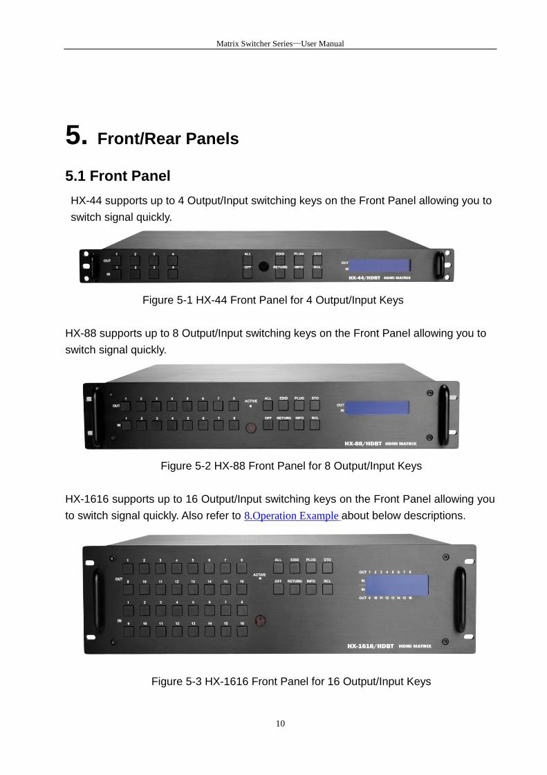
5.1 Front Panel
HX-44 supports up to 4 Output/Input switching keys on the Front Panel allowing you to
switch signal quickly.
Figure 5-1 HX-44 Front Panel for 4 Output/Input Keys
HX-88 supports up to 8 Output/Input switching keys on the Front Panel allowing you to
switch signal quickly.
Figure 5-2 HX-88 Front Panel for 8 Output/Input Keys
HX-1616 supports up to 16 Output/Input switching keys on the Front Panel allowing you
to switch signal quickly. Also refer to 8.Operation Example about below descriptions.
Figure 5-3 HX-1616 Front Panel for 16 Output/Input Keys

Matrix Switcher Series—User Manual
11
OUT1~4, 8 or 16 keys (output channel): Specify the Channel 1~Channel 4, 8 or 16 for
HDMI signal output. These keys configure the status or access the settings; you can
also use these keys to switch output channels.
IN1~4, 8 or 16 keys (input channel): Specify the Channel 1~Channel 4, 8 or 16 for
HDMI signal input. Use these keys to switch the connected input channels or use them
to instead of number keys upon memory selections.
ALL: This key allows user to set single input channel to all output channels. The usage
of “ALL” key is the same as output key.
- Press the “ALL” key.
- Select the one of the IN 1~4, 8 or 16 keys.
- The selected IN x key will transfer the input signal to all output channels.
- You can also press the “ALL” key and then press the “OFF” key to disable all
the displayed switching settings.
OFF: Disable the entire output channels. Press one of the OUT x keys that want to be
disabled for the output channel, then press the “OFF” key. Likewise, press the “ALL”
key and then press the “OFF” key to disable all the displayed switching settings. In
addition to switching port menu, press “OFF” key can return to the main screen during
implementing in other menu. You can also press “OFF” key to disable the light of LCD
screen for saving power.
EDID: FIX (fix mode) and OUT1 (access the first output channel) selection key.
- FIX mode: The Matrix Switcher supplies a set of fixed EDID values to support up
to only 1080P high performance TV.
- OUT1 mode: The Matrix Switcher will access the EDID values of high
performance TV that connected to the first output channel, and copy the EDID
value to all the input channels so that the DVD player can support to all the
HDTV.
RETURN: Press this key to go back to main screen.
PLUG: Press this key to show you the status of all HDMI Type A or RJ45 jacks on the
rear panel. If the HDMI or RJ45 jack is in HPD (hot plug detect), it will appear “O” on
the screen. Alternatively, it will appear “X” specified the HDMI or RJ45 jack is unused.
INFO: Press this key to show you the Matrix Switcher’s version, ID and IP address.
Press PLUG and INFO keys simultaneously to show you the firmware versions of
modules.
STO: The “Store Key” saves all current output/input corresponding relations up to 8
sets for a memory control.

Matrix Switcher Series—User Manual
12
- Press the “STO” key firstly.
- Arrange memory location. (Support up to 8 sets of memories, user can select
the memory location through OUT1~OUT8/IN1~IN8.)
- The relations among all settings will be saved in the memory permanently.
RCL: The “Retriever Key” retrieves all settings that are saved in the memory.
- Press the “RCL” key firstly.
- Then make a random to select one of output/input channel key 1~8.
- The system will retrieve the saved all status and implement current status
switching if the previously saving channel is selected.
Press and hold STO and RCL keys simultaneously at least 1 sec. to restore to factory
default values.
HX-44 Memory control only up to 4 sets
ACTIVE LED: A clear LED indicator designed for reaction by pressing keys on the front
panel and remote controller. Refer to Appendix A Matrix Switcher Remote Controller.
Only HX-88 / HX-1616.
IR Receiver: Infrared receiver can receive signals from the Matrix Switcher Remote
Controller.
LCD: LCD display shows current Matrix Switcher status and operation status.
Press any keys on the front panel or controller to enable the light of LCD momentarily.
This function cannot be controlled by RS-232 or LAN.
Matrix Switching System—User Manual
13
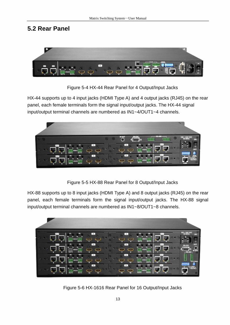
5.2 Rear Panel
Figure 5-4 HX-44 Rear Panel for 4 Output/Input Jacks
HX-44 supports up to 4 input jacks (HDMI Type A) and 4 output jacks (RJ45) on the rear
panel, each female terminals form the signal input/output jacks. The HX-44 signal
input/output terminal channels are numbered as IN1~4/OUT1~4 channels.
Figure 5-5 HX-88 Rear Panel for 8 Output/Input Jacks
HX-88 supports up to 8 input jacks (HDMI Type A) and 8 output jacks (RJ45) on the rear
panel, each female terminals form the signal input/output jacks. The HX-88 signal
input/output terminal channels are numbered as IN1~8/OUT1~8 channels.
Figure 5-6 HX-1616 Rear Panel for 16 Output/Input Jacks

Matrix Switcher Series—User Manual
14
The HX-1616 supports up to 16 input jacks (HDMI Type A) and 16 output jacks (RJ45)
on the rear panel, each female terminals form the signal input/output jacks. The HX-1616
signal input/output terminal channels are numbered as IN1~16/OUT1~16 channels. The
input terminal channels supply you to connect to different equipment including
Blu-ray/DVD players, graphics workstations, and number displays. The output jacks
allow you to connect to extensible accessory devices for over long connections with
terminals just like projectors, video recorders, displays and multiplexers and so on.
Power Port: The Power Port is applicable for 100~240VAC, 50~60Hz connected to the
outlet of power source. Refer to 6.4 Power Connection.
Power Switch: To switch power ON or OFF the Matrix Switcher.
RS-232: Use a 9-pin RS-232 cable to connect both computer serial port (COM1 or
COM2) and Matrix Switcher RS-232 communication port, refer to 6.6.1 RS-232. The
computer then can be deployed to control the Matrix Switcher after installing of
application software. Refer to 7.1 Software Introduction for a software control or
Appendix D RS-232 Communication Protocol for an individual configuration.
RS-485: Connection ports allow you to connect/control more than one Matrix product,
refer to 6.6.2 RS-485.
LAN Port: Use the RJ45 connection cable to connect the Internet and the Matrix
Switcher. The entire PCs at the same network can control the Matrix Switcher through
the LAN port. Refer to 6.6.3 LAN Port.
Switchers: Matrix Switcher supports 8 pins DIP and 2 pins DIP switchers for
connected configurations. For more information, refer to 6.6 Ports and Switchers.
- Pin 1~Pin5: ID - Pin 6: Master/Slave - Pin 7: RS-232/LAN - Pin 8: IP RESET
IR EXT: This is used to connect the IR Receiver Cable for the Matrix Switcher Remote
Controller. Refer to 6.3 IR EXT Connection.
INPUT1~4, 8 or 16: Matrix Switcher Input jacks are connected to the Blu-ray players,
DVD players, STBs or other source devices.
HDMI Type A: Pin Definitions:
Pin # Signal Pin # Signal
1 TMDS Data2+ 11 TMDS Clock Shield
2 TMDS Data2 Shield 12 TMDS Clock-
3 TMDS Data2- 13 CEC (NC on device)

Matrix Switcher Series—User Manual
15
4 TMDS Data1+ 14 Utility (NC on device)
5 TMDS Data1 Shield 15 DDC-SCL
6 TMDS Data1- 16 DDC-SDA
7 TMDS Data0+ 17 DDC-Ground
8 TMDS Data0 Shield
18 +5V Power
9 TMDS Data0- 19 Hot Plug Detect
10 TMDS Clock+
OUTPUT1~4, 8 or 16: Matrix Switcher Output jacks are connected to extensible
accessory devices (HVX-100-R) for HDTVs, projectors or other sink devices
connection.
OUTPUT1~8 or 16 RJ45 jacks are only used for extender (HVX-100-R) connection.
IR Tx1~4, 8 or 16 Ports: Used to connect to the IR Blaster Cable for IR pass-through.
IR Emitter:
IR Rx1~8 or 16 Ports: Used to connect to the IR Receiver Cable for IR pass-through.
IR Receiver Pin Definitions:
6. Matrix Switcher and Peripherals Connections
Figure 6-1 HX-44 Connections
Matrix Switcher Series—User Manual
16
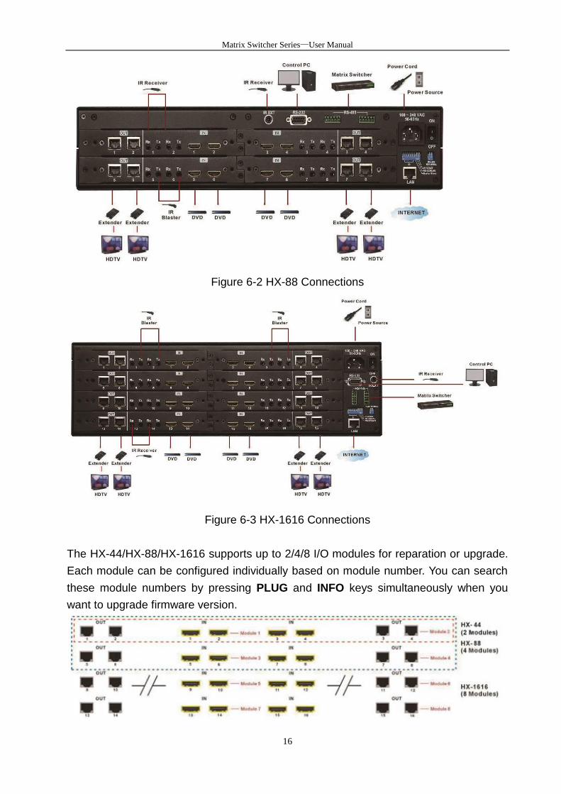
Figure 6-2 HX-88 Connections
Figure 6-3 HX-1616 Connections
The HX-44/HX-88/HX-1616 supports up to 2/4/8 I/O modules for reparation or upgrade.
Each module can be configured individually based on module number. You can search
these module numbers by pressing PLUG and INFO keys simultaneously when you
want to upgrade firmware version.

Matrix Switcher Series—User Manual
17
Figure 6-4 Modules Deployment
Matrix Switcher Series—User Manual
18
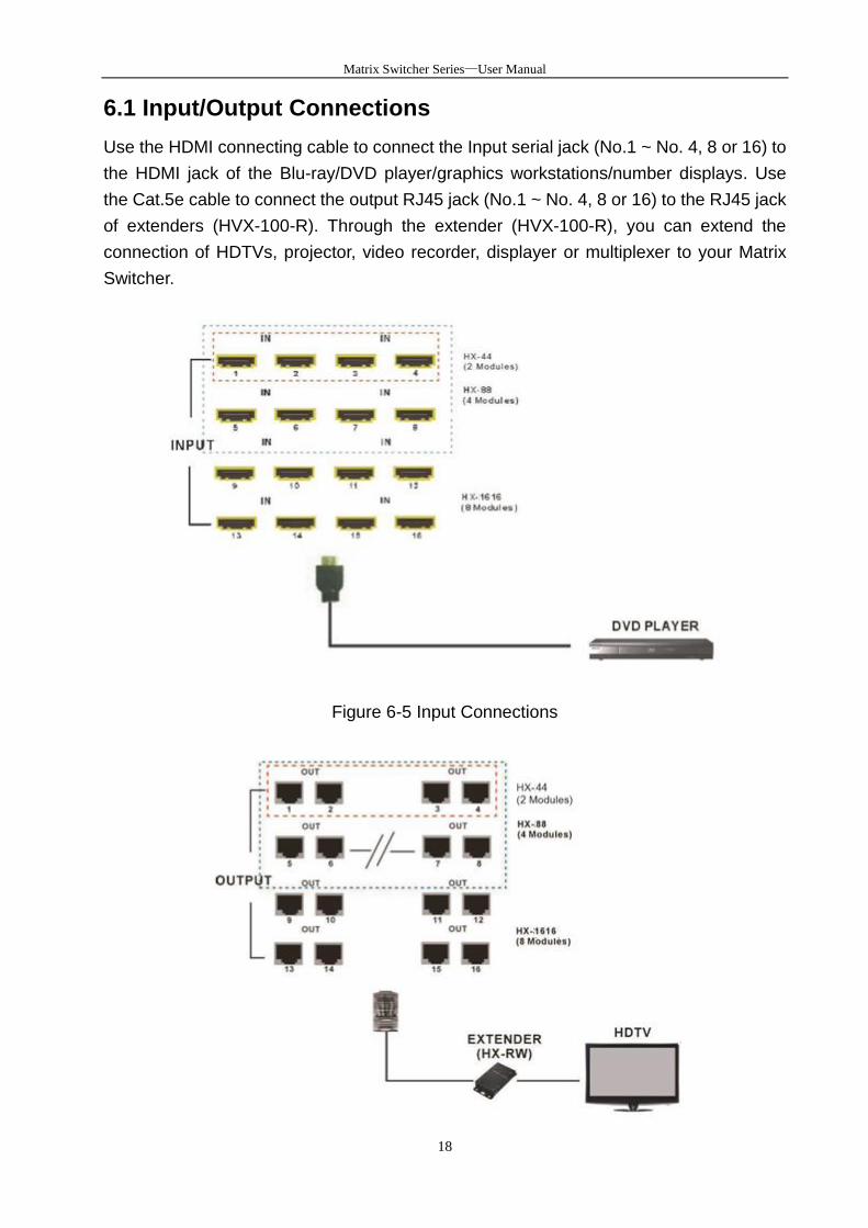
6.1 Input/Output Connections
Use the HDMI connecting cable to connect the Input serial jack (No.1 ~ No. 4, 8 or 16) to
the HDMI jack of the Blu-ray/DVD player/graphics workstations/number displays. Use
the Cat.5e cable to connect the output RJ45 jack (No.1 ~ No. 4, 8 or 16) to the RJ45 jack
of extenders (HVX-100-R). Through the extender (HVX-100-R), you can extend the
connection of HDTVs, projector, video recorder, displayer or multiplexer to your Matrix
Switcher.
Figure 6-5 Input Connections

Matrix Switcher Series—User Manual
19
Figure 6-6 Output Connections
6.1.1 Output LED
This Matrix Switcher supports HDBaseT output for a long distance signal transmission.
Output connector is RJ45 jack with two LED indicators. The LED indicators show you the
status of output transmission.
* The left of RJ45 output jack is specified for HDCP LED (Yellow).
* The right of RJ45 output jack is specified for LINK LED (Green).
The LED indicators are only designed for the Output – RJ45 jack of Matrix Switcher.
LED Indicators:
LED Off Blink On
LINK
(Green) No Link Low Power Mode HDBaseT Link
HDCP
(Yellow) No HDMI Signals No Encryption HDCP Encryption
6.1.2 Output Cable
HDBaseT was designed to provide Full HD performance up to 100 meters of Cat.5e or
superior cables. In a typical installation, the cable is stretched to its full length between
the HDBaseT Transmitter device and the HDBaseT Receiver device. However
sometimes, especially, in demonstrations or in a lab environment, the cable is rolled
randomly in small turns for convenience. The randomly rolled UTP cable suffers
additional signal impairments (compared to straight cable) and therefore the maximal
operating reach might be reduced. When a Cat.5e cable is randomly rolled, it is
recommended to limit its length to approximate 50 meters. Rolling a Cat.5e cable around
a 70cm fixed diameter plastic drum has just a minor effect on the FEXT (Far End Cross
Talk) when compared to a fully stretched cable.
Matrix Switching System—User Manual
20
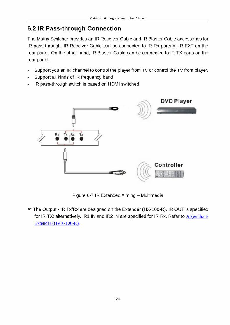
6.2 IR Pass-through Connection
The Matrix Switcher provides an IR Receiver Cable and IR Blaster Cable accessories for
IR pass-through. IR Receiver Cable can be connected to IR Rx ports or IR EXT on the
rear panel. On the other hand, IR Blaster Cable can be connected to IR TX ports on the
rear panel.
- Support you an IR channel to control the player from TV or control the TV from player.
- Support all kinds of IR frequency band
- IR pass-through switch is based on HDMI switched
Figure 6-7 IR Extended Aiming – Multimedia
The Output - IR Tx/Rx are designed on the Extender (HX-100-R). IR OUT is specified
for IR TX; alternatively, IR1 IN and IR2 IN are specified for IR Rx. Refer to Appendix E
Extender (HVX-100-R).
Matrix Switcher Series—User Manual
21
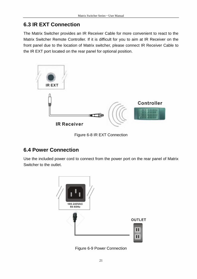
6.3 IR EXT Connection
The Matrix Switcher provides an IR Receiver Cable for more convenient to react to the
Matrix Switcher Remote Controller. If it is difficult for you to aim at IR Receiver on the
front panel due to the location of Matrix switcher, please connect IR Receiver Cable to
the IR EXT port located on the rear panel for optional position.
Figure 6-8 IR EXT Connection
6.4 Power Connection
Use the included power cord to connect from the power port on the rear panel of Matrix
Switcher to the outlet.
Figure 6-9 Power Connection
Matrix Switcher Series—User Manual
22
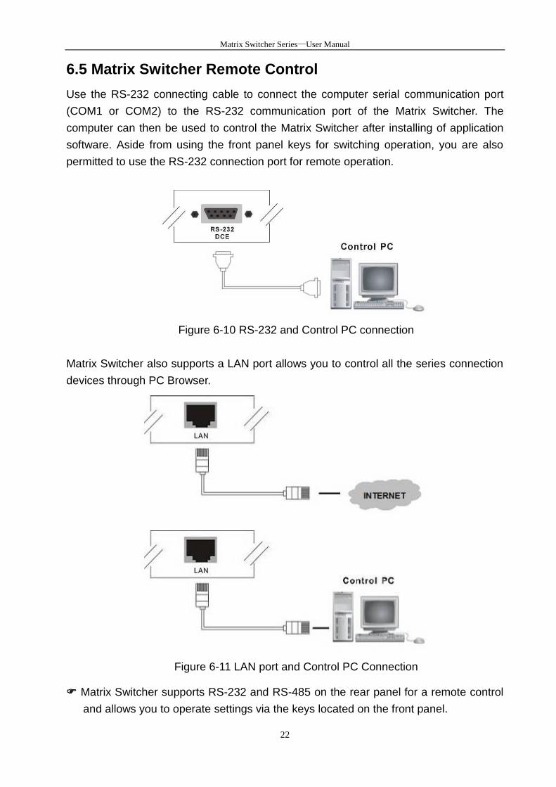
6.5 Matrix Switcher Remote Control
Use the RS-232 connecting cable to connect the computer serial communication port
(COM1 or COM2) to the RS-232 communication port of the Matrix Switcher. The
computer can then be used to control the Matrix Switcher after installing of application
software. Aside from using the front panel keys for switching operation, you are also
permitted to use the RS-232 connection port for remote operation.
Figure 6-10 RS-232 and Control PC connection
Matrix Switcher also supports a LAN port allows you to control all the series connection
devices through PC Browser.
Figure 6-11 LAN port and Control PC Connection
Matrix Switcher supports RS-232 and RS-485 on the rear panel for a remote control
and allows you to operate settings via the keys located on the front panel.
Matrix Switching System—User Manual
23
6.6 Ports and Switchers
The Matrix Switcher provides standard RS-232 and RS-485 serial communication ports.
Beside the front panel for key switching operation, you can also use the RS-232 or
RS-485 serial communication port to carry out remote operation.
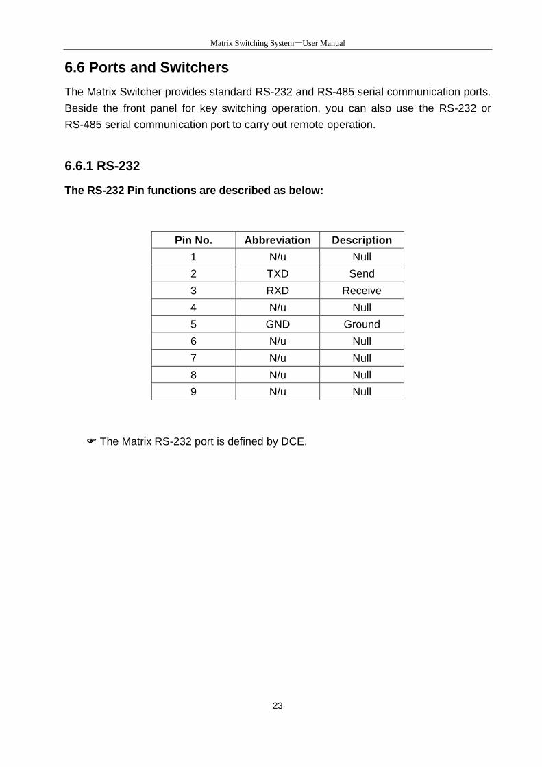
6.6.1 RS-232
The RS-232 Pin functions are described as below:
Pin No. Abbreviation Description
1 N/u Null
2 TXD Send
3 RXD Receive
4 N/u Null
5 GND Ground
6 N/u Null
7 N/u Null
8 N/u Null
9 N/u Null
The Matrix RS-232 port is defined by DCE.
Matrix Switcher Series—User Manual
24
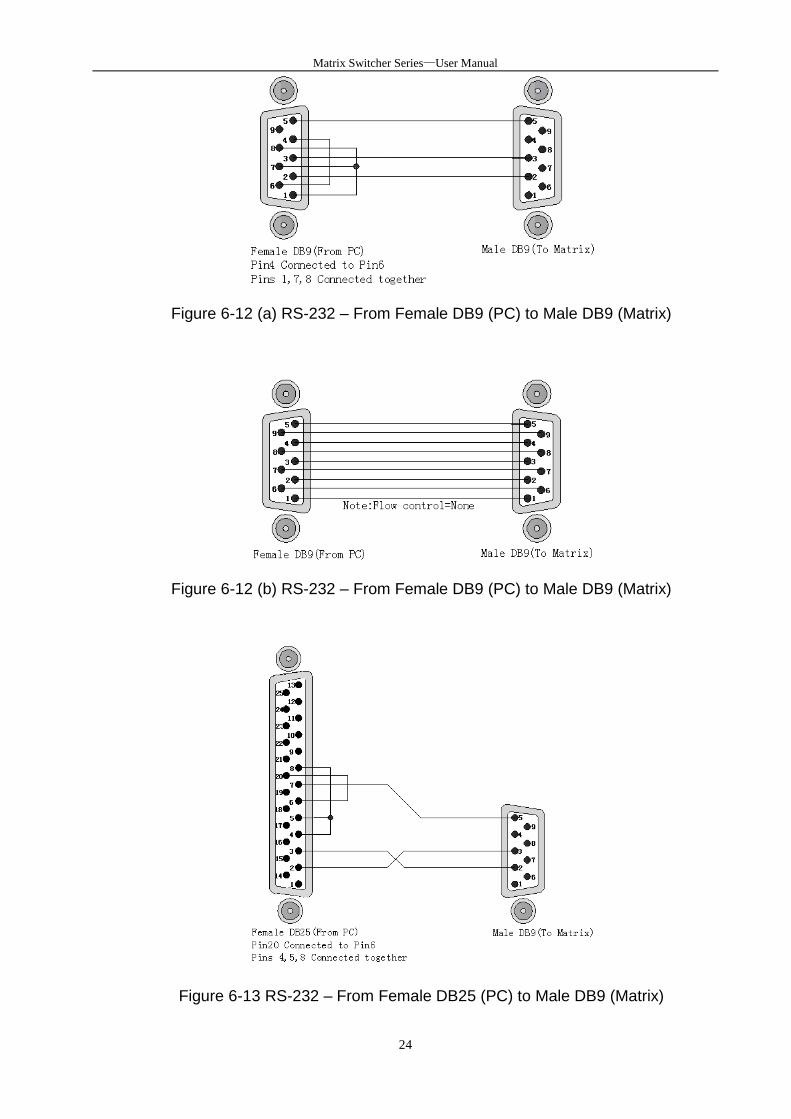
Figure 6-12 (a) RS-232 – From Female DB9 (PC) to Male DB9 (Matrix)
Figure 6-12 (b) RS-232 – From Female DB9 (PC) to Male DB9 (Matrix)
Figure 6-13 RS-232 – From Female DB25 (PC) to Male DB9 (Matrix)
Matrix Switcher Series—User Manual
25
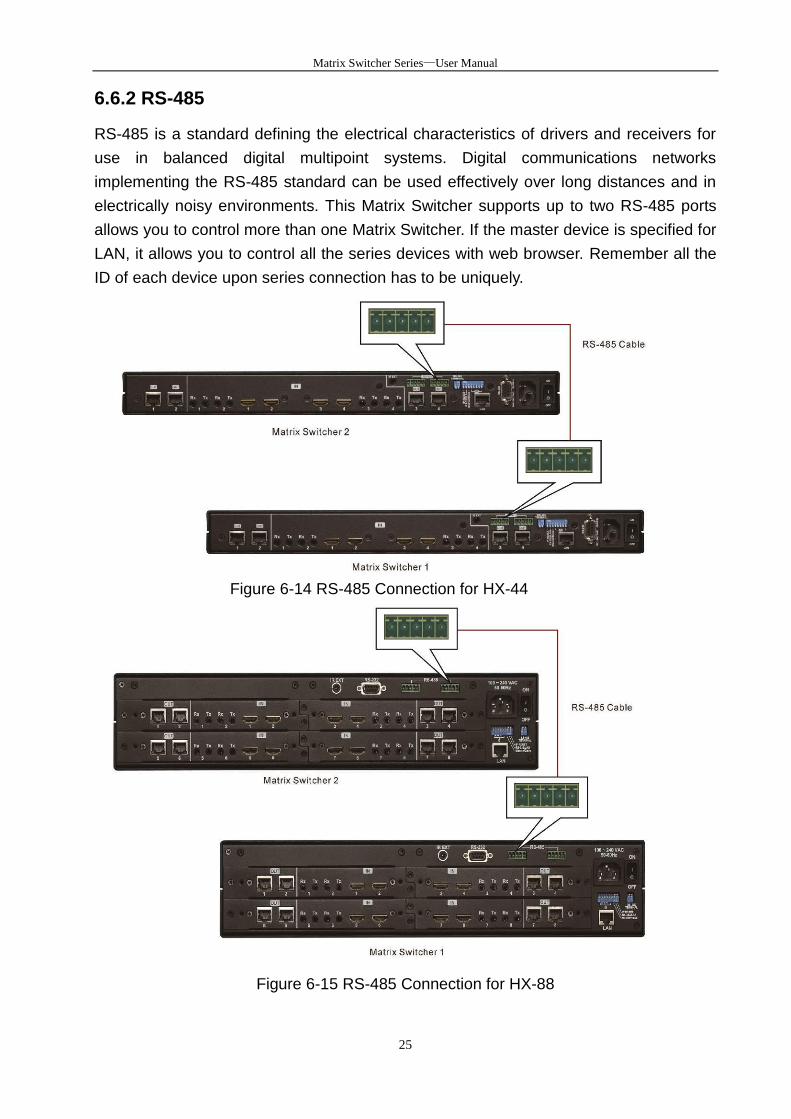
6.6.2 RS-485
RS-485 is a standard defining the electrical characteristics of drivers and receivers for
use in balanced digital multipoint systems. Digital communications networks
implementing the RS-485 standard can be used effectively over long distances and in
electrically noisy environments. This Matrix Switcher supports up to two RS-485 ports
allows you to control more than one Matrix Switcher. If the master device is specified for
LAN, it allows you to control all the series devices with web browser. Remember all the
ID of each device upon series connection has to be uniquely.
Figure 6-14 RS-485 Connection for HX-44
Figure 6-15 RS-485 Connection for HX-88
Matrix Switcher Series—User Manual
26
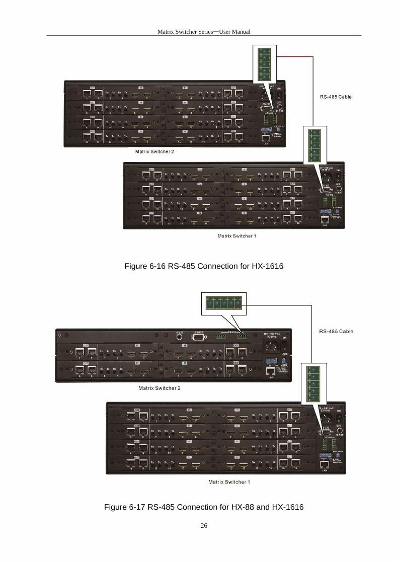
Figure 6-16 RS-485 Connection for HX-1616
Figure 6-17 RS-485 Connection for HX-88 and HX-1616
Matrix Switcher Series—User Manual
27
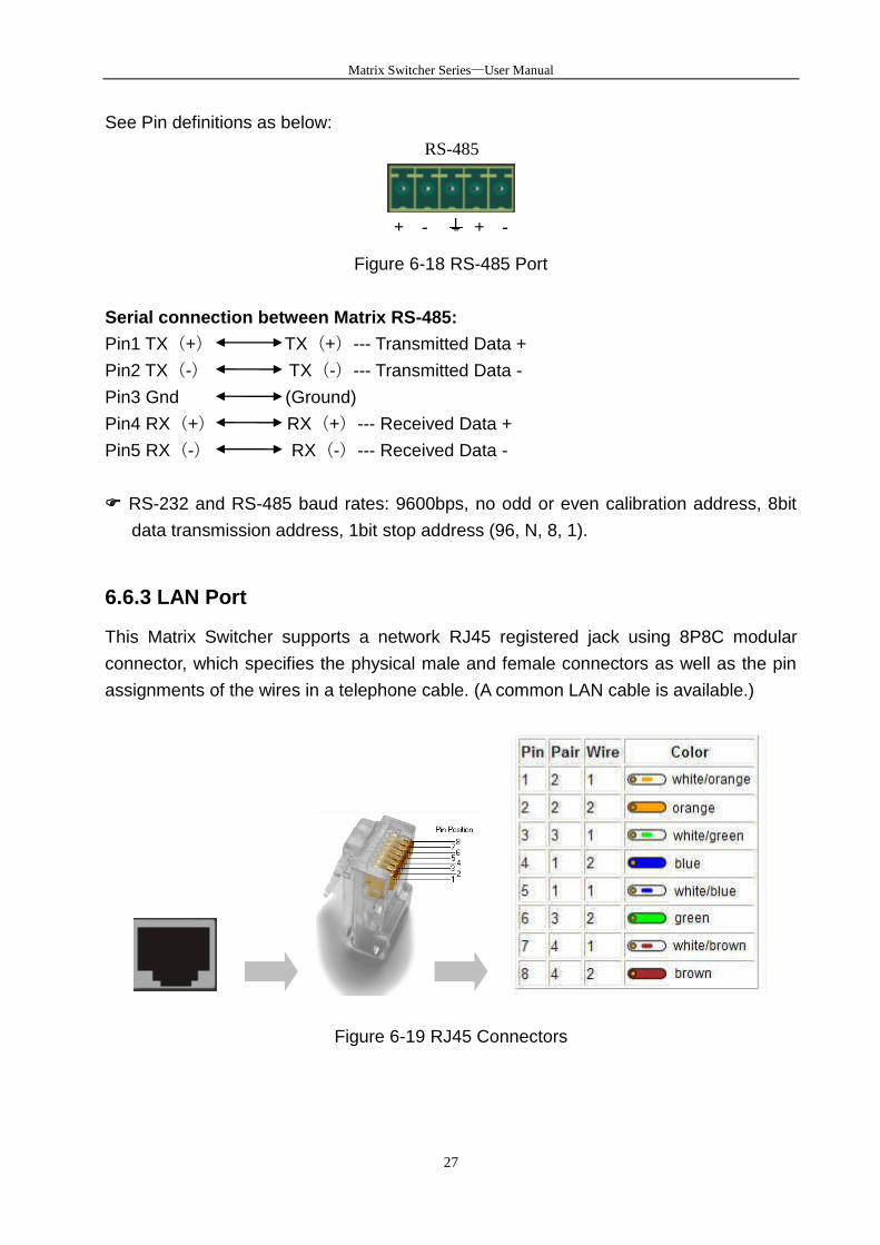
See Pin definitions as below:
RS-485
+ - + -
Figure 6-18 RS-485 Port
Serial connection between Matrix RS-485:
Pin1 TX(+) TX(+)--- Transmitted Data +
Pin2 TX(-) TX(-)--- Transmitted Data -
Pin3 Gnd (Ground)
Pin4 RX(+) RX(+)--- Received Data +
Pin5 RX(-) RX(-)--- Received Data -
RS-232 and RS-485 baud rates: 9600bps, no odd or even calibration address, 8bit
data transmission address, 1bit stop address (96, N, 8, 1).
6.6.3 LAN Port
This Matrix Switcher supports a network RJ45 registered jack using 8P8C modular
connector, which specifies the physical male and female connectors as well as the pin
assignments of the wires in a telephone cable. (A common LAN cable is available.)
Figure 6-19 RJ45 Connectors

Matrix Switcher Series—User Manual
28
6.6.4 DIP Switcher 8 Pins
Figure 6-20 DIP Switchers
A. DIP Switcher Pin 1 to 5: Switch to down (ON) is specified for “0”, on the other hand
to up (OFF) be specified for “1”. For Device ID settings refer to 6.6.6 Device ID Settings.
B. DIP Switcher Pin 6: Mater/Slave Enable/Disable. Only one Matrix Switcher can be
connected to other device and control PC via RS-232/LAN that is specified as Master,
others are specified as Slave.
ON: RS-485 Serial Master and RS-232 / LAN Enable.
OFF: RS-485 Serial Slave and RS-232 / LAN Disable.
C. DIP Switcher Pin 7: Switch between RS-232 port and LAN port connection.
ON: RS-232
OFF: LAN
D. DIP Switcher Pin 8: Reset the web server IP address to 192.168.0.3
The steps are as below:
1. Please adjust the pin8 to ON and re-start the Matrix Switcher.
2. After the Matrix Switcher re-starts about 10 seconds, shut down it.
3. For a normal operation, please adjust the pin8 to OFF, then power on the Matrix
Switcher again. The IP address will be restored to the default value: 192.168.0.3
6.6.5 DIP Switcher 2 Pins
Figure 6-21 RS-485 Terminal Switchers
DIP Switch RS-485 Terminator: RS-485 Terminator for ON/OFF
ON: RS-485 Terminator ON.
OFF: RS-485 Terminator OFF.
Proceed Multi Matrix Switcher connections, the RS-485 Terminator for the last device
Matrix Switcher Series—User Manual
29
must be set to ON. Others must be set to OFF.
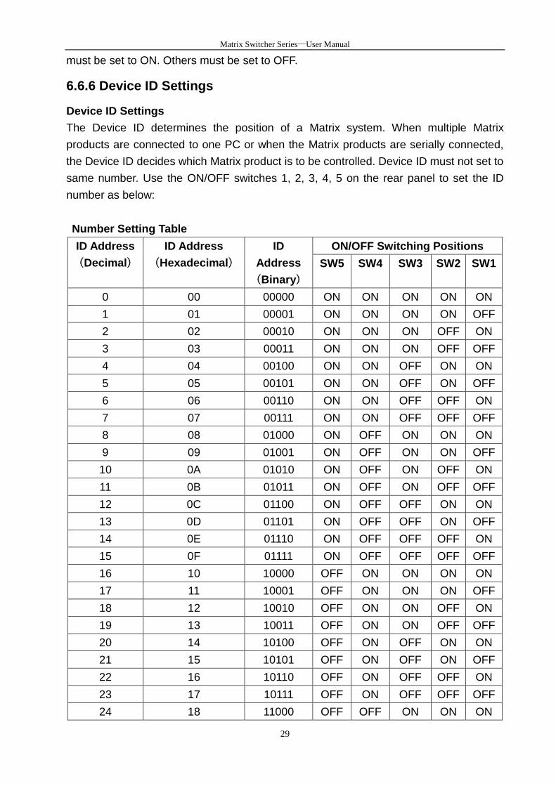
6.6.6 Device ID Settings
Device ID Settings
The Device ID determines the position of a Matrix system. When multiple Matrix
products are connected to one PC or when the Matrix products are serially connected,
the Device ID decides which Matrix product is to be controlled. Device ID must not set to
same number. Use the ON/OFF switches 1, 2, 3, 4, 5 on the rear panel to set the ID
number as below:
Number Setting Table
ID Address
(Decimal)
ID Address
(Hexadecimal)
ID
Address
(Binary)
ON/OFF Switching Positions
SW5 SW4 SW3 SW2 SW1
0 00 00000 ON ON ON ON ON
1 01 00001 ON ON ON ON OFF
2 02 00010 ON ON ON OFF ON
3 03 00011 ON ON ON OFF OFF
4 04 00100 ON ON OFF ON ON
5 05 00101 ON ON OFF ON OFF
6 06 00110 ON ON OFF OFF ON
7 07 00111 ON ON OFF OFF OFF
8 08 01000 ON OFF ON ON ON
9 09 01001 ON OFF ON ON OFF
10 0A 01010 ON OFF ON OFF ON
11 0B 01011 ON OFF ON OFF OFF
12 0C 01100 ON OFF OFF ON ON
13 0D 01101 ON OFF OFF ON OFF
14 0E 01110 ON OFF OFF OFF ON
15 0F 01111 ON OFF OFF OFF OFF
16 10 10000 OFF ON ON ON ON
17 11 10001 OFF ON ON ON OFF
18 12 10010 OFF ON ON OFF ON
19 13 10011 OFF ON ON OFF OFF
20 14 10100 OFF ON OFF ON ON
21 15 10101 OFF ON OFF ON OFF
22 16 10110 OFF ON OFF OFF ON
23 17 10111 OFF ON OFF OFF OFF
24 18 11000 OFF OFF ON ON ON

Matrix Switcher Series—User Manual
30
25 19 11001 OFF OFF ON ON OFF
26 1A 11010 OFF OFF ON OFF ON
27 1B 11011 OFF OFF ON OFF OFF
28 1C 11100 OFF OFF OFF ON ON
29 1D 11101 OFF OFF OFF ON OFF
30 1E 11110 OFF OFF OFF OFF ON
31 1F 11111 OFF OFF OFF OFF OFF
Matrix Switcher Series—User Manual
31
7. Matrix Application Software
7.1 Software Introduction
The 《AV Matrix》 matrix control software applies to different input/output matrixes.
7.1.1 Software Description
The 《AV Matrix》 matrix testing software is an application tool developed for matrix
testing and application. The software operation environment is as below:
- Window98/2000/NT/XP operating systems - 32M internal memory or above - 10M hard disk space or above - CD-ROM - At least one serial communication port
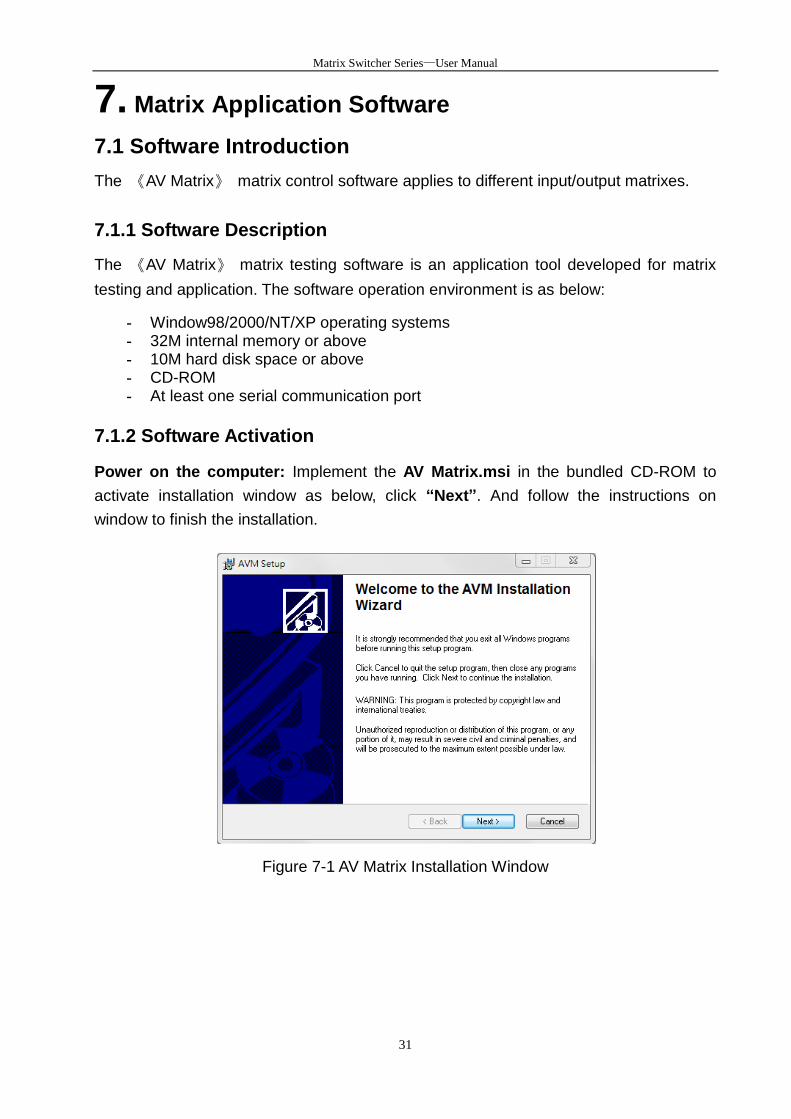
7.1.2 Software Activation
Power on the computer: Implement the AV Matrix.msi in the bundled CD-ROM to
activate installation window as below, click “Next”. And follow the instructions on
window to finish the installation.
Figure 7-1 AV Matrix Installation Window
Matrix Switcher Series—User Manual
32
7.1.3 Connect Matrix Switcher and PC
You must power off the Matrix Switcher. Then, connect the Matrix RS-232 port to the PC
RS-232 port with the bundled communication cable. And make sure the DIPs on the rear
panel are set to Master and RS-232. (Refer to the previous section 6.6.1 RS-232)
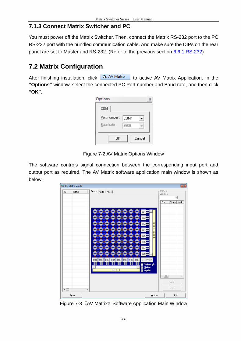
7.2 Matrix Configuration
After finishing installation, click to active AV Matrix Application. In the
“Options” window, select the connected PC Port number and Baud rate, and then click
“OK”.
Figure 7-2 AV Matrix Options Window
The software controls signal connection between the corresponding input port and
output port as required. The AV Matrix software application main window is shown as
below:
Figure 7-3《AV Matrix》Software Application Main Window
Matrix Switcher Series—User Manual
33
The Device ID is based on the DIP of switcher located on the rear panel.
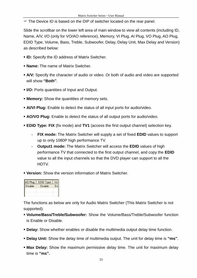
Slide the scrollbar on the lower left area of main window to view all contents (including ID,
Name, A/V, I/O (only for VO/AO reference), Memory, VI Plug, AI Plug, VO Plug, AO Plug,
EDID Type, Volume, Bass, Treble, Subwoofer, Delay, Delay Unit, Max Delay and Version)
as described below:
ID: Specify the ID address of Matrix Switcher.
Name: The name of Matrix Switcher.
A/V: Specify the character of audio or video. Or both of audio and video are supported
will show “Both”.
I/O: Ports quantities of Input and Output.
Memory: Show the quantities of memory sets.
AI/VI Plug: Enable to detect the status of all input ports for audio/video.
AO/VO Plug: Enable to detect the status of all output ports for audio/video.
EDID Type: FIX (fix mode) and TV1 (access the first output channel) selection key.
- FIX mode: The Matrix Switcher will supply a set of fixed EDID values to support
up to only 1080P high performance TV.
- Output1 mode: The Matrix Switcher will access the EDID values of high
performance TV that connected to the first output channel, and copy the EDID
value to all the input channels so that the DVD player can support to all the
HDTV.
Version: Show the version information of Matrix Switcher.
The functions as below are only for Audio Matrix Switcher (This Matrix Switcher is not
supported):
Volume/Bass/Treble/Subwoofer: Show the Volume/Bass/Treble/Subwoofer function
is Enable or Disable.
Delay: Show whether enables or disable the multimedia output delay time function.
Delay Unit: Show the delay time of multimedia output. The unit for delay time is “ms”.
Max Delay: Show the maximum permissive delay time. The unit for maximum delay
time is “ms”.
Matrix Switching System—User Manual
34
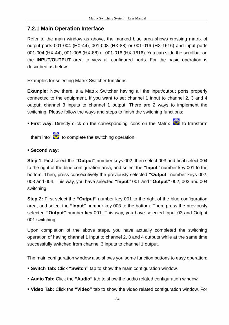
7.2.1 Main Operation Interface
Refer to the main window as above, the marked blue area shows crossing matrix of
output ports 001-004 (HX-44), 001-008 (HX-88) or 001-016 (HX-1616) and input ports
001-004 (HX-44), 001-008 (HX-88) or 001-016 (HX-1616). You can slide the scrollbar on
the INPUT/OUTPUT area to view all configured ports. For the basic operation is
described as below:
Examples for selecting Matrix Switcher functions:
Example: Now there is a Matrix Switcher having all the input/output ports properly
connected to the equipment. If you want to set channel 1 input to channel 2, 3 and 4
output; channel 3 inputs to channel 1 output. There are 2 ways to implement the
switching. Please follow the ways and steps to finish the switching functions:
First way: Directly click on the corresponding icons on the Matrix to transform
them into to complete the switching operation.
Second way:
Step 1: First select the “Output” number keys 002, then select 003 and final select 004
to the right of the blue configuration area, and select the “Input” number key 001 to the
bottom. Then, press consecutively the previously selected “Output” number keys 002,
003 and 004. This way, you have selected “Input” 001 and “Output” 002, 003 and 004
switching.
Step 2: First select the “Output” number key 001 to the right of the blue configuration
area, and select the “Input” number key 003 to the bottom. Then, press the previously
selected “Output” number key 001. This way, you have selected Input 03 and Output
001 switching.
Upon completion of the above steps, you have actually completed the switching
operation of having channel 1 input to channel 2, 3 and 4 outputs while at the same time
successfully switched from channel 3 inputs to channel 1 output.
The main configuration window also shows you some function buttons to easy operation:
Switch Tab: Click “Switch” tab to show the main configuration window.
Audio Tab: Click the “Audio” tab to show the audio related configuration window.
Video Tab: Click the “Video” tab to show the video related configuration window. For
Matrix Switcher Series—User Manual
35
more information, refer to 7.2.4 EDID Configuration Function.
Disconnect: To disable the connections. After you had configured the connection
between input and output ports, you can click this button to disable the connections
Select all output: Click this button to select all output ports including output 001-004
(HX-44), 001-008 (HX-88) or 001-016 (HX-1616).
Video check box: Used for video configurations.
Audio check box: Used for audio configurations.
Scan: To search the device controlled by the AV Matrix Application configuration.
When the device name located on the left of main configuration window is empty, you
can click the Scan to research and update the device ID and Name and other related
information. End the Scan function by pressing the Scan again during scanning
process. And the left of main configuration window will show you the detected
information presently.
Options: Allows you to configure the Port number and Baud rate.
Exit: Click this button to exit the configuration window.
Save: Click this button to save the connected combinations both output ports and input
ports into the memory set.
Load: Click this button to retrieve the previously saved settings.
For more information and operations, please refer to next chapters.
Matrix Switching System—User Manual
36
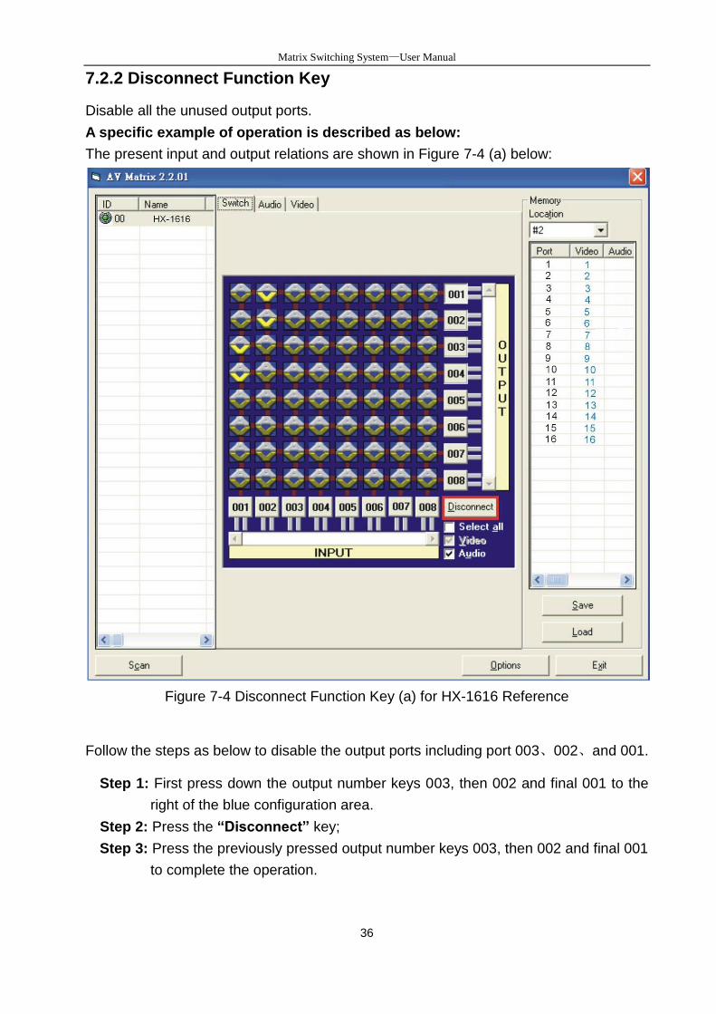
7.2.2 Disconnect Function Key
Disable all the unused output ports.
A specific example of operation is described as below:
The present input and output relations are shown in Figure 7-4 (a) below:
Figure 7-4 Disconnect Function Key (a) for HX-1616 Reference
Follow the steps as below to disable the output ports including port 003、002、and 001.
Step 1: First press down the output number keys 003, then 002 and final 001 to the
right of the blue configuration area.
Step 2: Press the “Disconnect” key;
Step 3: Press the previously pressed output number keys 003, then 002 and final 001
to complete the operation.
Matrix Switcher Series—User Manual
37
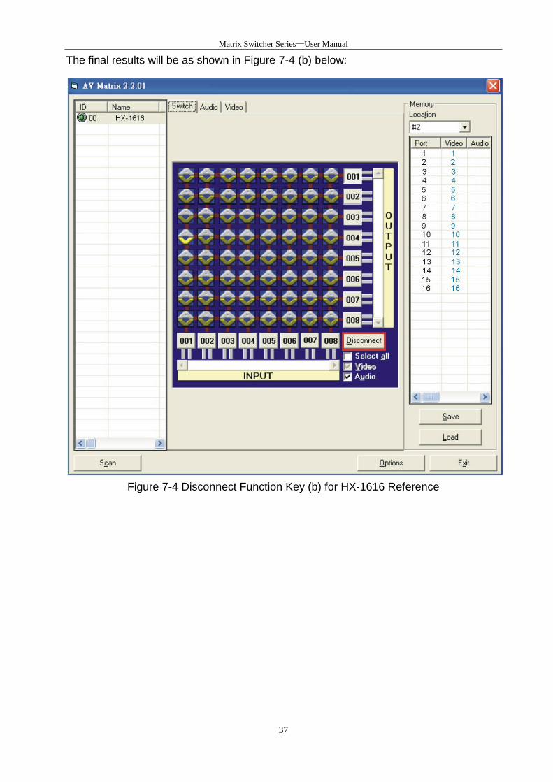
The final results will be as shown in Figure 7-4 (b) below:
Figure 7-4 Disconnect Function Key (b) for HX-1616 Reference
Matrix Switcher Series—User Manual
38
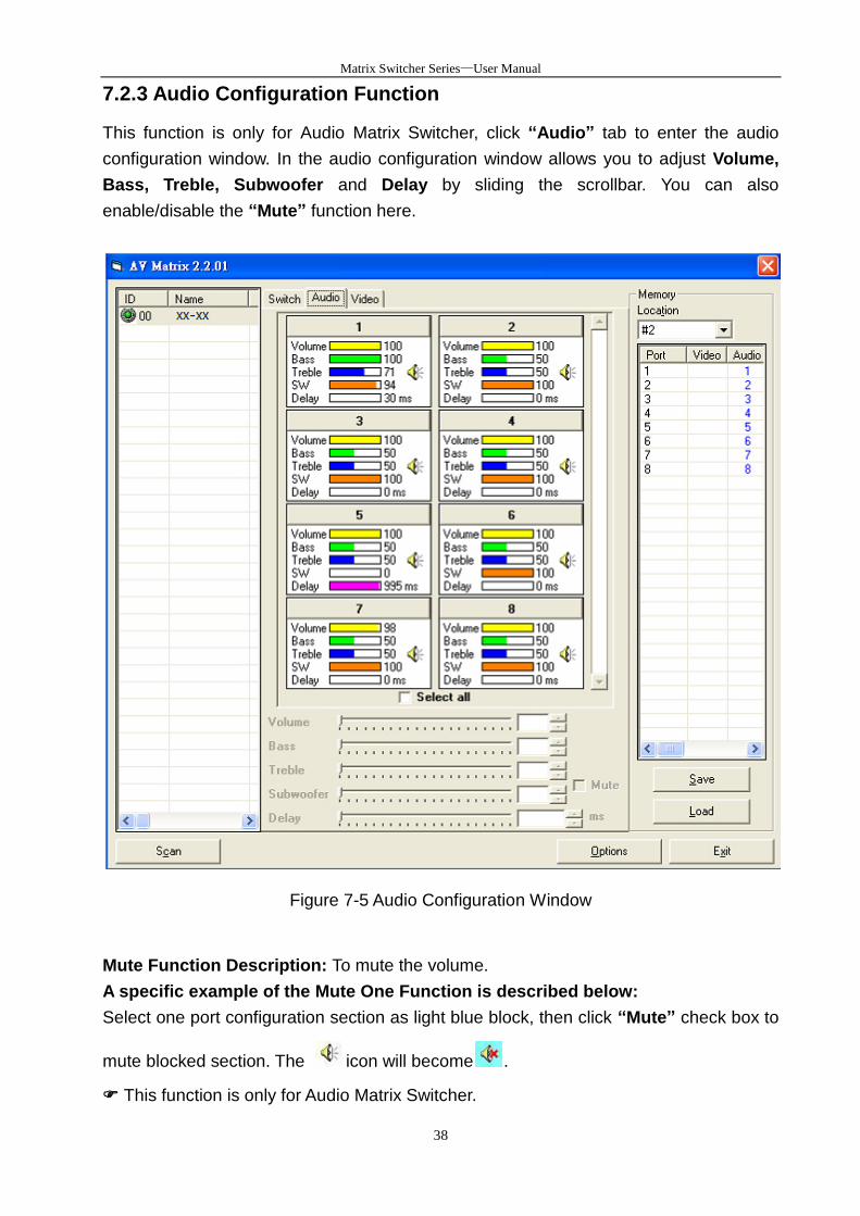
7.2.3 Audio Configuration Function
This function is only for Audio Matrix Switcher, click “Audio” tab to enter the audio
configuration window. In the audio configuration window allows you to adjust Volume,
Bass, Treble, Subwoofer and Delay by sliding the scrollbar. You can also
enable/disable the “Mute” function here.
Figure 7-5 Audio Configuration Window
Mute Function Description: To mute the volume.
A specific example of the Mute One Function is described below:
Select one port configuration section as light blue block, then click “Mute” check box to
mute blocked section. The icon will become .
This function is only for Audio Matrix Switcher.
Matrix Switcher Series—User Manual
39
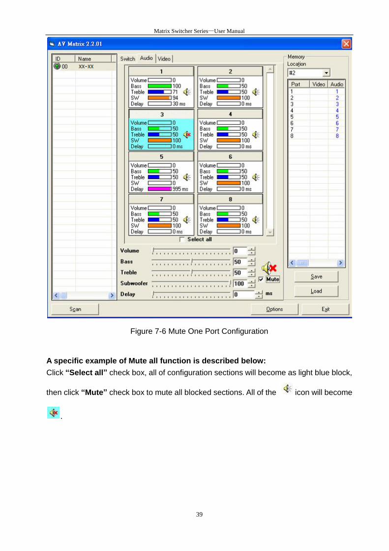
Figure 7-6 Mute One Port Configuration
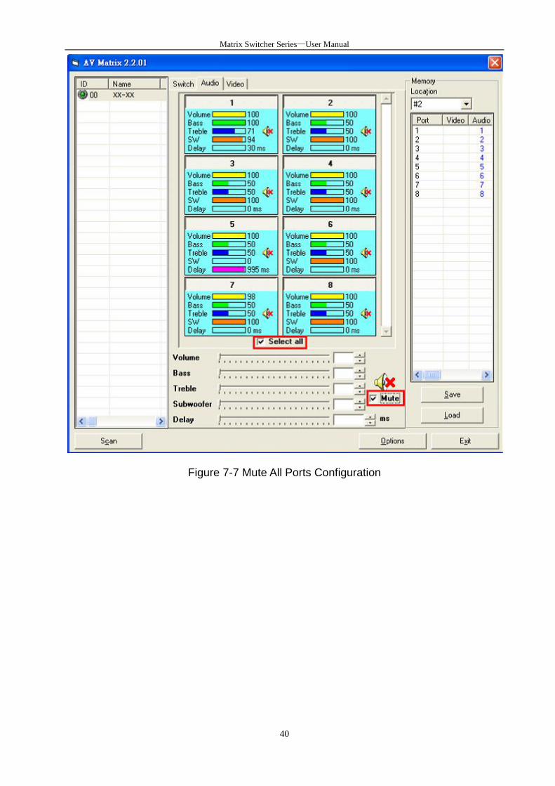
A specific example of Mute all function is described below:
Click “Select all” check box, all of configuration sections will become as light blue block,
then click “Mute” check box to mute all blocked sections. All of the icon will become
.
Matrix Switcher Series—User Manual
40
Figure 7-7 Mute All Ports Configuration
Matrix Switcher Series—User Manual
41
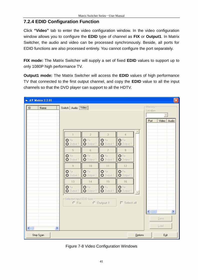
7.2.4 EDID Configuration Function
Click “Video” tab to enter the video configuration window. In the video configuration
window allows you to configure the EDID type of channel as FIX or Output1. In Matrix
Switcher, the audio and video can be processed synchronously. Beside, all ports for
EDID functions are also processed entirely. You cannot configure the port separately.
FIX mode: The Matrix Switcher will supply a set of fixed EDID values to support up to
only 1080P high performance TV.
Output1 mode: The Matrix Switcher will access the EDID values of high performance
TV that connected to the first output channel, and copy the EDID value to all the input
channels so that the DVD player can support to all the HDTV.
Figure 7-8 Video Configuration Windows
Matrix Switcher Series—User Manual
42
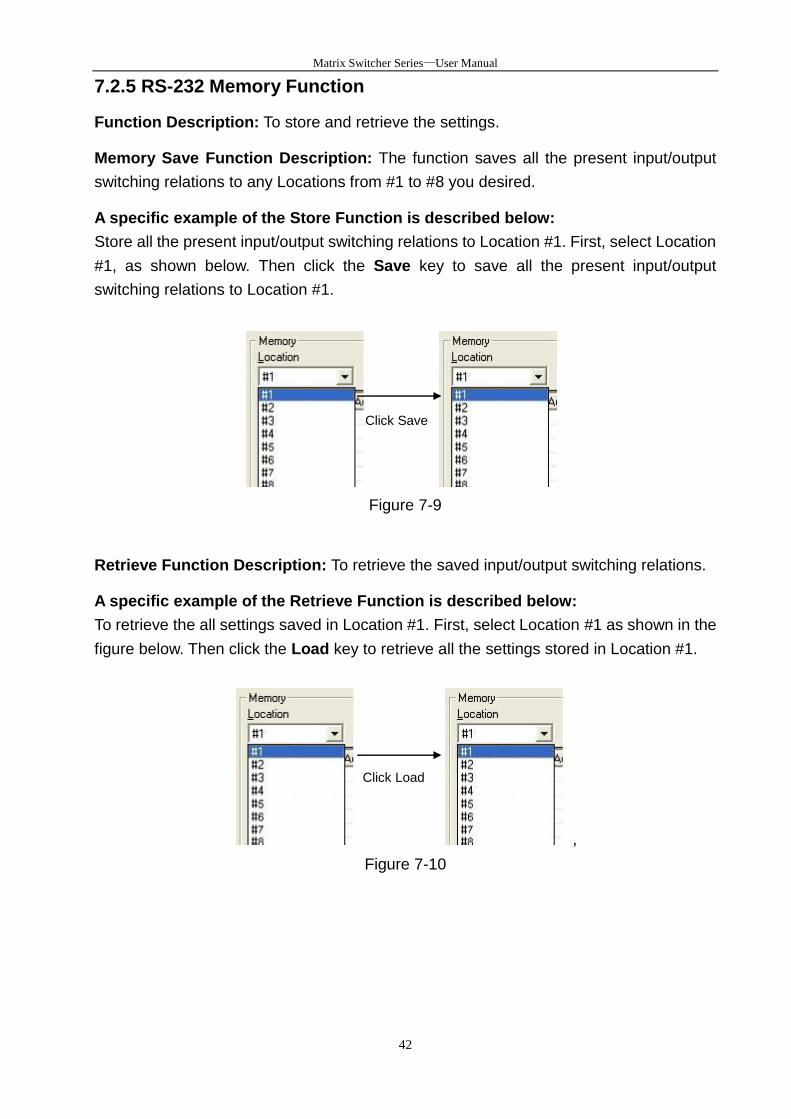
7.2.5 RS-232 Memory Function
Function Description: To store and retrieve the settings.
Memory Save Function Description: The function saves all the present input/output
switching relations to any Locations from #1 to #8 you desired.
A specific example of the Store Function is described below:
Store all the present input/output switching relations to Location #1. First, select Location
#1, as shown below. Then click the Save key to save all the present input/output
switching relations to Location #1.
Figure 7-9
Retrieve Function Description: To retrieve the saved input/output switching relations.
A specific example of the Retrieve Function is described below:
To retrieve the all settings saved in Location #1. First, select Location #1 as shown in the
figure below. Then click the Load key to retrieve all the settings stored in Location #1.
,
Figure 7-10
Click Save
Click Load
Matrix Switcher Series—User Manual
43
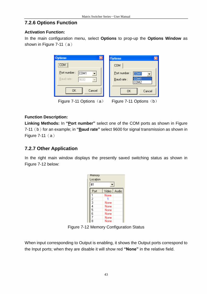
7.2.6 Options Function
Activation Function:
In the main configuration menu, select Options to prop-up the Options Window as
shown in Figure 7-11(a)
Figure 7-11 Options(a) Figure 7-11 Options(b)
Function Description:
Linking Methods: In “Port number” select one of the COM ports as shown in Figure
7-11(b)for an example; in “Baud rate” select 9600 for signal transmission as shown in
Figure 7-11(a)
7.2.7 Other Application
In the right main window displays the presently saved switching status as shown in
Figure 7-12 below:
Figure 7-12 Memory Configuration Status
When input corresponding to Output is enabling, it shows the Output ports correspond to
the Input ports; when they are disable it will show red “None” in the relative field.

Matrix Switcher Series—User Manual
44
7.2.8 Communication Protocol/Control Command Code
Communication Protocol: Baud rate 9600bps, no odd or even calibration bit address,
8bit transmission address, 1bit stop address. Please refer to the “Command list.pdf” in
the CD-ROM for more relative Command Code information. Also see Appendix D
RS-232 Communication Protocol.
Matrix Switching System—User Manual
45
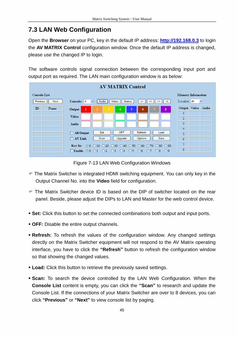
7.3 LAN Web Configuration
Open the Browser on your PC, key in the default IP address: http://192.168.0.3 to login
the AV MATRIX Control configuration window. Once the default IP address is changed,
please use the changed IP to login.
The software controls signal connection between the corresponding input port and
output port as required. The LAN main configuration window is as below:
Figure 7-13 LAN Web Configuration Windows
The Matrix Switcher is integrated HDMI switching equipment. You can only key in the
Output Channel No. into the Video field for configuration.
The Matrix Switcher device ID is based on the DIP of switcher located on the rear
panel. Beside, please adjust the DIPs to LAN and Master for the web control device.
Set: Click this button to set the connected combinations both output and input ports.
OFF: Disable the entire output channels.
Refresh: To refresh the values of the configuration window. Any changed settings
directly on the Matrix Switcher equipment will not respond to the AV Matrix operating
interface, you have to click the “Refresh” button to refresh the configuration window
so that showing the changed values.
Load: Click this button to retrieve the previously saved settings.
Scan: To search the device controlled by the LAN Web Configuration. When the
Console List content is empty, you can click the “Scan” to research and update the
Console List. If the connections of your Matrix Switcher are over to 8 devices, you can
click “Previous” or “Next” to view console list by paging.
Matrix Switcher Series—User Manual
46
Upgrade: Use for firmware upgrade. For more information, refer to Appendix C
Firmware Upgrade .
Options: Allow you to configure the IP address.
Save: Click this button to save the connected combinations output and input ports. It
also includes the present input/output switching relations and all settings.
For more relative information, refer to 5.1 Front Panel as “STO” key function.
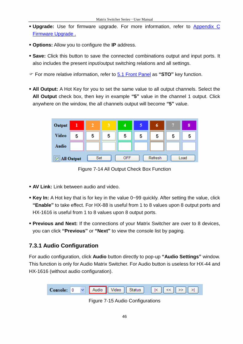
All Output: A Hot Key for you to set the same value to all output channels. Select the
All Output check box, then key in example “5” value in the channel 1 output. Click
anywhere on the window, the all channels output will become “5” value.
Figure 7-14 All Output Check Box Function
AV Link: Link between audio and video.
Key In: A Hot key that is for key in the value 0~99 quickly. After setting the value, click
“Enable” to take effect. For HX-88 is useful from 1 to 8 values upon 8 output ports and
HX-1616 is useful from 1 to 8 values upon 8 output ports.
Previous and Next: If the connections of your Matrix Switcher are over to 8 devices,
you can click “Previous” or “Next” to view the console list by paging.
7.3.1 Audio Configuration
For audio configuration, click Audio button directly to pop-up “Audio Settings” window.
This function is only for Audio Matrix Switcher. For Audio button is useless for HX-44 and
HX-1616 (without audio configuration).
Figure 7-15 Audio Configurations
Matrix Switcher Series—User Manual
47
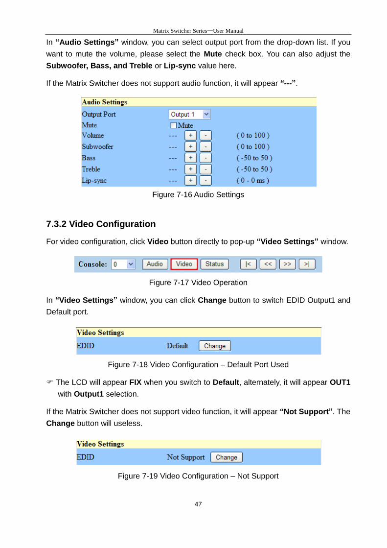
In “Audio Settings” window, you can select output port from the drop-down list. If you
want to mute the volume, please select the Mute check box. You can also adjust the
Subwoofer, Bass, and Treble or Lip-sync value here.
If the Matrix Switcher does not support audio function, it will appear “---”.
Figure 7-16 Audio Settings
7.3.2 Video Configuration
For video configuration, click Video button directly to pop-up “Video Settings” window.
Figure 7-17 Video Operation
In “Video Settings” window, you can click Change button to switch EDID Output1 and
Default port.
Figure 7-18 Video Configuration – Default Port Used
The LCD will appear FIX when you switch to Default, alternately, it will appear OUT1
with Output1 selection.
If the Matrix Switcher does not support video function, it will appear “Not Support”. The
Change button will useless.
Figure 7-19 Video Configuration – Not Support
Matrix Switcher Series—User Manual
48
7.3.3 Device Status Information
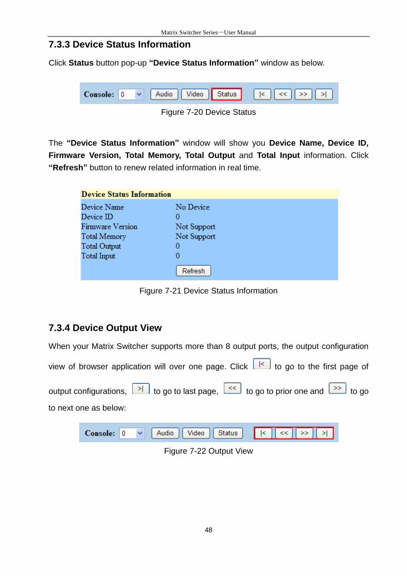
Click Status button pop-up “Device Status Information” window as below.
Figure 7-20 Device Status
The “Device Status Information” window will show you Device Name, Device ID,
Firmware Version, Total Memory, Total Output and Total Input information. Click
“Refresh” button to renew related information in real time.
Figure 7-21 Device Status Information
7.3.4 Device Output View
When your Matrix Switcher supports more than 8 output ports, the output configuration
view of browser application will over one page. Click to go to the first page of
output configurations, to go to last page, to go to prior one and to go
to next one as below:
Figure 7-22 Output View
Matrix Switcher Series—User Manual
49
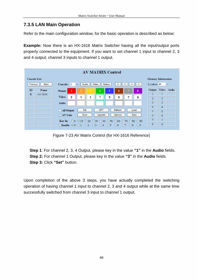
7.3.5 LAN Main Operation
Refer to the main configuration window, for the basic operation is described as below:
Example: Now there is an HX-1616 Matrix Switcher having all the input/output ports
properly connected to the equipment. If you want to set channel 1 input to channel 2, 3
and 4 output; channel 3 inputs to channel 1 output.
Figure 7-23 AV Matrix Control (for HX-1616 Reference)
Step 1: For channel 2, 3, 4 Output, please key in the value “1” in the Audio fields.
Step 2: For channel 1 Output, please key in the value “3” in the Audio fields.
Step 3: Click “Set” button.
Upon completion of the above 3 steps, you have actually completed the switching
operation of having channel 1 input to channel 2, 3 and 4 output while at the same time
successfully switched from channel 3 input to channel 1 output.
Matrix Switching System—User Manual
50
7.3.6 LAN Memory Function
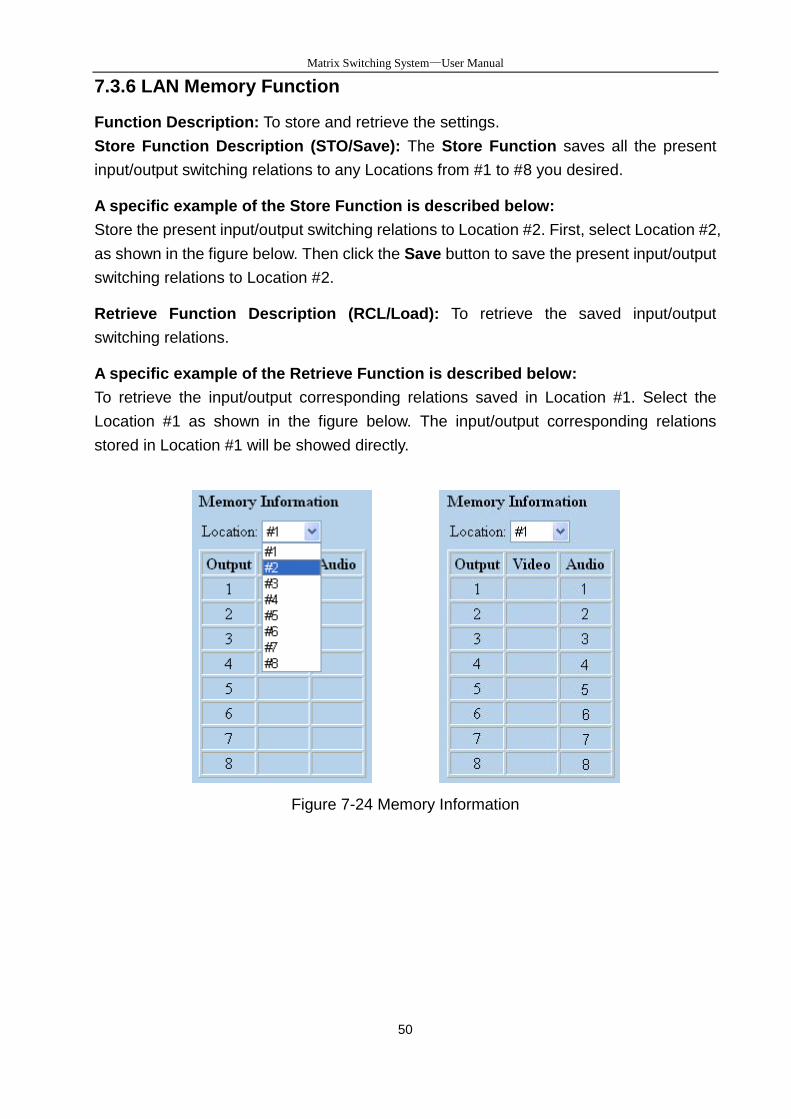
Function Description: To store and retrieve the settings.
Store Function Description (STO/Save): The Store Function saves all the present
input/output switching relations to any Locations from #1 to #8 you desired.
A specific example of the Store Function is described below:
Store the present input/output switching relations to Location #2. First, select Location #2,
as shown in the figure below. Then click the Save button to save the present input/output
switching relations to Location #2.
Retrieve Function Description (RCL/Load): To retrieve the saved input/output
switching relations.
A specific example of the Retrieve Function is described below:
To retrieve the input/output corresponding relations saved in Location #1. Select the
Location #1 as shown in the figure below. The input/output corresponding relations
stored in Location #1 will be showed directly.
Figure 7-24 Memory Information
Matrix Switching System—User Manual
51
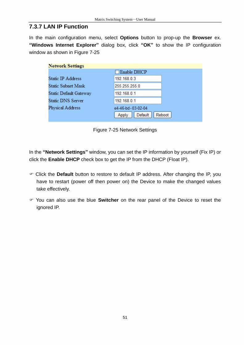
7.3.7 LAN IP Function
In the main configuration menu, select Options button to prop-up the Browser ex.
“Windows Internet Explorer” dialog box, click “OK” to show the IP configuration
window as shown in Figure 7-25
Figure 7-25 Network Settings
In the “Network Settings” window, you can set the IP information by yourself (Fix IP) or
click the Enable DHCP check box to get the IP from the DHCP (Float IP).
Click the Default button to restore to default IP address. After changing the IP, you
have to restart (power off then power on) the Device to make the changed values
take effectively.
You can also use the blue Switcher on the rear panel of the Device to reset the
ignored IP.
Matrix Switching System—User Manual
52
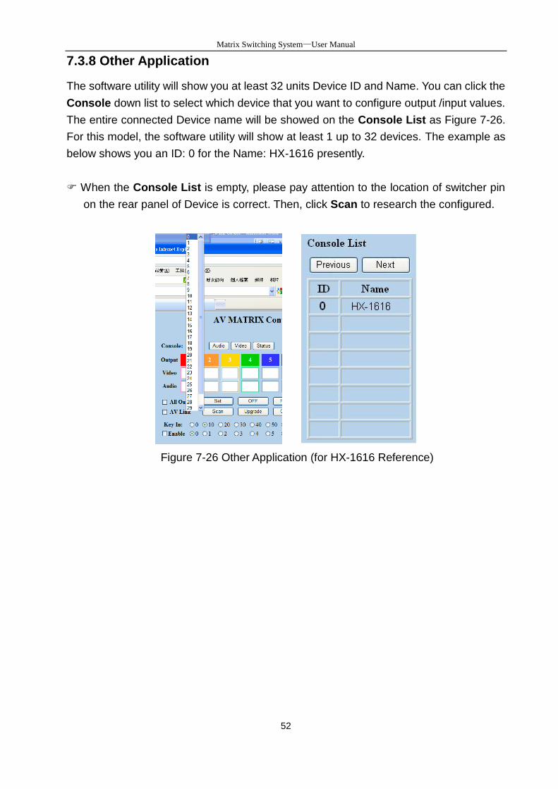
7.3.8 Other Application
The software utility will show you at least 32 units Device ID and Name. You can click the
Console down list to select which device that you want to configure output /input values.
The entire connected Device name will be showed on the Console List as Figure 7-26.
For this model, the software utility will show at least 1 up to 32 devices. The example as
below shows you an ID: 0 for the Name: HX-1616 presently.
When the Console List is empty, please pay attention to the location of switcher pin
on the rear panel of Device is correct. Then, click Scan to research the configured.
Figure 7-26 Other Application (for HX-1616 Reference)
Matrix Switching System—User Manual
53
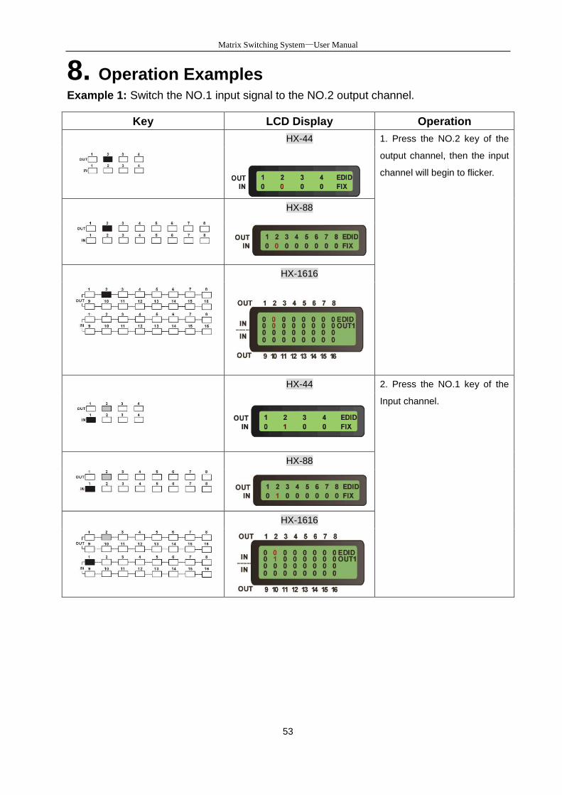
8. Operation Examples Example 1: Switch the NO.1 input signal to the NO.2 output channel.
Key LCD Display Operation
HX-44 1. Press the NO.2 key of the
output channel, then the input
channel will begin to flicker.
HX-88
HX-1616
HX-44 2. Press the NO.1 key of the
Input channel.
HX-88
HX-1616
Matrix Switcher Series—User Manual
54
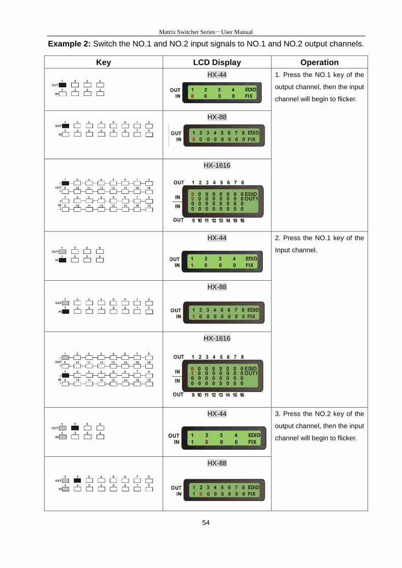
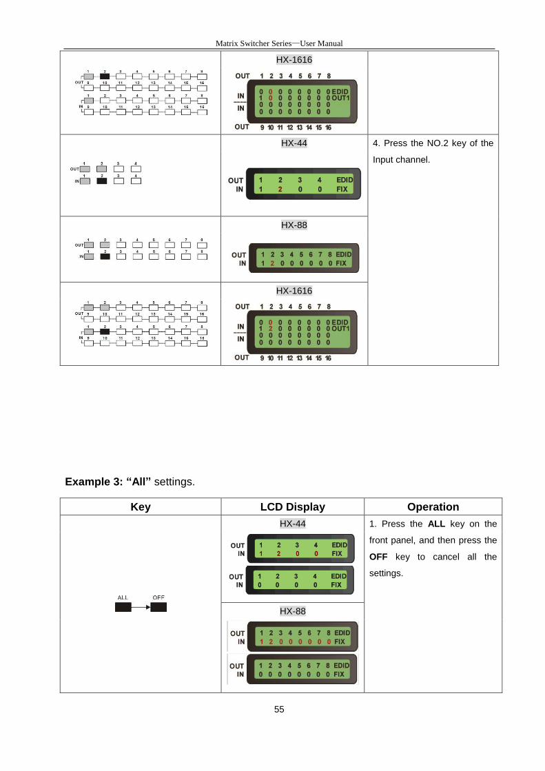
Example 2: Switch the NO.1 and NO.2 input signals to NO.1 and NO.2 output channels.
Key LCD Display Operation
HX-44 1. Press the NO.1 key of the
output channel, then the input
channel will begin to flicker.
HX-88
HX-1616
HX-44 2. Press the NO.1 key of the
Input channel.
HX-88
HX-1616
HX-44 3. Press the NO.2 key of the
output channel, then the input
channel will begin to flicker.
HX-88
Matrix Switcher Series—User Manual
55
HX-1616
HX-44 4. Press the NO.2 key of the
Input channel.
HX-88
HX-1616
Example 3: “All” settings.
Key LCD Display Operation
HX-44 1. Press the ALL key on the
front panel, and then press the
OFF key to cancel all the
settings.
HX-88
Matrix Switcher Series—User Manual
56
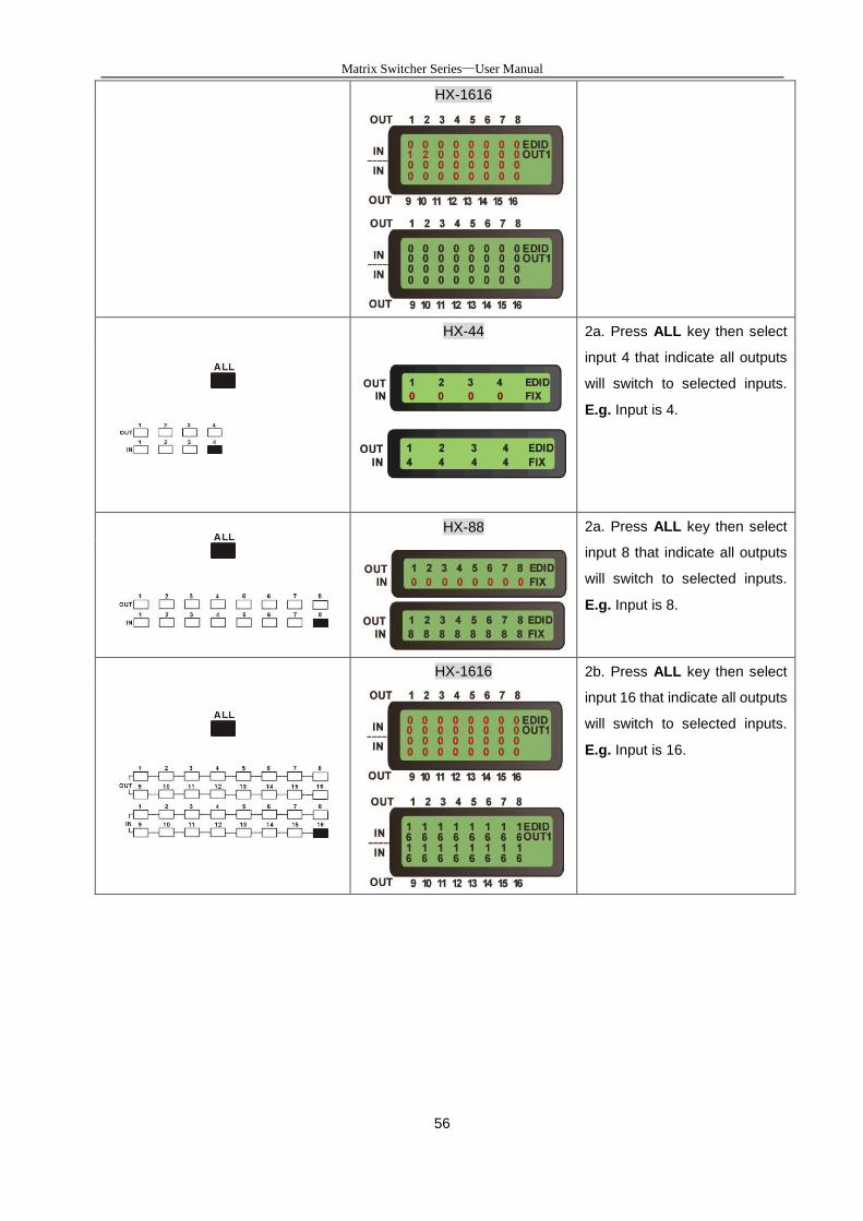
HX-1616
HX-44 2a. Press ALL key then select
input 4 that indicate all outputs
will switch to selected inputs.
E.g. Input is 4.
HX-88 2a. Press ALL key then select
input 8 that indicate all outputs
will switch to selected inputs.
E.g. Input is 8.
HX-1616 2b. Press ALL key then select
input 16 that indicate all outputs
will switch to selected inputs.
E.g. Input is 16.
Matrix Switcher Series—User Manual
57
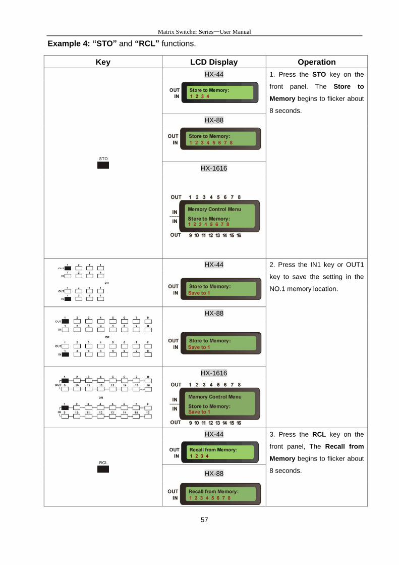
Example 4: “STO” and “RCL” functions.
Key LCD Display Operation
HX-44 1. Press the STO key on the
front panel. The Store to
Memory begins to flicker about
8 seconds.
HX-88
HX-1616
HX-44 2. Press the IN1 key or OUT1
key to save the setting in the
NO.1 memory location.
HX-88
HX-1616
HX-44 3. Press the RCL key on the
front panel, The Recall from
Memory begins to flicker about
8 seconds.
HX-88
Matrix Switcher Series—User Manual
58
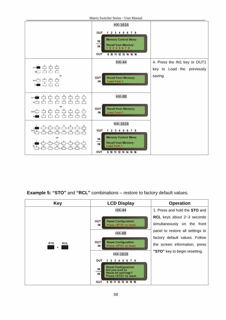
HX-1616
HX-44 4. Press the IN1 key or OUT1
key to Load the previously
saving.
HX-88
HX-1616
Example 5: “STO” and “RCL” combinations – restore to factory default values.
Key LCD Display Operation
HX-44 1. Press and hold the STO and
RCL keys about 2~3 seconds
simultaneously on the front
panel to restore all settings to
factory default values. Follow
the screen information, press
“STO” key to begin resetting.
HX-88
HX-1616
Matrix Switcher Series—User Manual
59
HX-44 2. After finish resetting, All of
settings will restore to the
factory default values.
HX-88
HX-1616
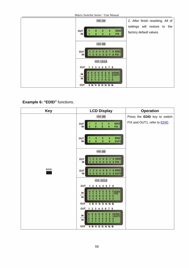
Example 6: “EDID” functions.
Key LCD Display Operation
HX-88 Press the EDID key to switch
FIX and OUT1, refer to EDID.
HX-88
HX-1616
Matrix Switcher Series—User Manual
60
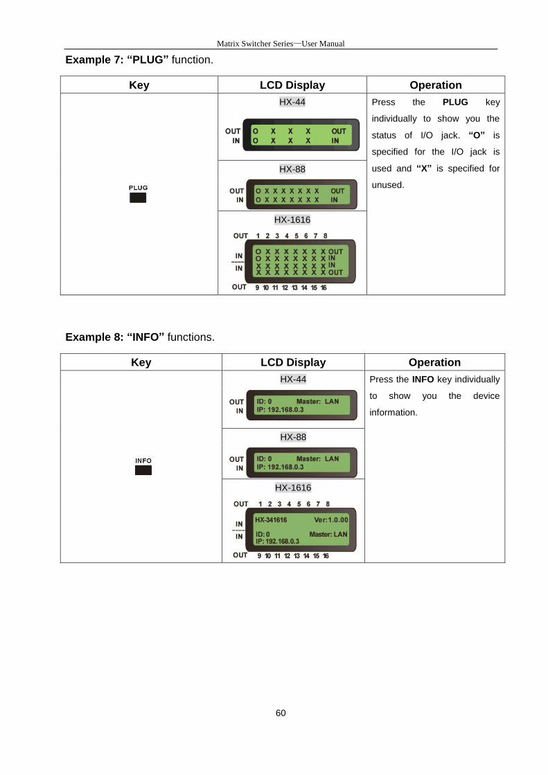
Example 7: “PLUG” function.
Key LCD Display Operation
HX-44 Press the PLUG key
individually to show you the
status of I/O jack. “O” is
specified for the I/O jack is
used and “X” is specified for
unused.
HX-88
HX-1616
Example 8: “INFO” functions.
Key LCD Display Operation
HX-44 Press the INFO key individually
to show you the device
information.
HX-88
HX-1616
Matrix Switcher Series—User Manual
61
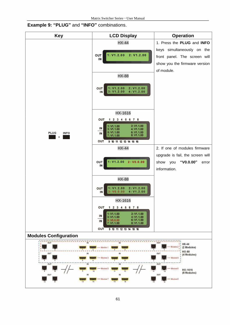
Example 9: “PLUG” and “INFO” combinations.
Key LCD Display Operation
HX-44 1. Press the PLUG and INFO
keys simultaneously on the
front panel. The screen will
show you the firmware version
of module.
HX-88
HX-1616
HX-44 2. If one of modules firmware
upgrade is fail, the screen will
show you “V0.0.00” error
information.
HX-88
HX-1616
Modules Configuration

Matrix Switcher Series—User Manual
62
9. Troubleshooting
1. What to do if LCD is fail in display?
Answer: Check the connection of power cord is not loosening and the power cord is in a
good status having no any damage. Check the power source is normally.
2. What to do if the HDMI Matrix front panel keys switching not responsive?
Answer: The HDMI Matrix front panel keys employ scanning testing and require longer
response time. Press the keys for 2 seconds and then release. This way, key
switching will be responsive in operation.
3. What to do if the serial port (usually refer to the computer serial port) fails to control the
HDMI Matrix?
Answer: Check that the communication port set by the control software is correctly
connected to the corresponding serial port of the equipment. Also, check if the
computer communication port is in good order. Check the ID address and DIP
Switcher are configured correctly. Refer to 6.6.6 Device ID Settings and 6.6.5
DIP Switcher 2 Pins.
4. What to do if the corresponding audio signal fails to output during HDMI Matrix
switching?
Answer:
(1) Check if there is signal on the input end. If there is no input signal, it could be that the
input connection cable is broken or the connector gets loosen. You are advised to
replace the connection cable.
(2) Check if there is signal on the output end. If there is no output signal, it could be that
the cable is broken or the connector gets loosen. You are advised to replace the
connection cable.
(3) Check if the output port number is the same as the controlled port number.
(4) Check the connections of input and output ports are correctly.
(5) If none of the above circumstances happen, it could be internal failure of the product
itself. You must send for repair by qualified technical engineers.

Matrix Switcher Series—User Manual
63
5. What to do if you sense the power leakage during plugging or unplugging of the
input/output ports?
Answer: It could be that the equipment power is not properly grounded. You must
properly ground your equipment; otherwise product life can easily be shortened.
6. What to do if the HDMI Matrix panel keys and communication ports are out of order?
Answer: Check if the equipment power input is in good contact and the computer
communication ports are in good order. If yes, it could be some internal failure of the
product, please send for repair by qualified technical engineer.
7. What to do if operation and function failure occurred?
Answer: Check if the equipment and the Matrix system are in proper connection. If the
problem persists, send the product to the maintenance center for repair.
8. How to avoid the equipment failure due to the high temperature?
Answer: Place the equipment in a ventilate location. If it is still not to be improved,
please check with the build-in fan whether is damaged. Or contact your agency for
helping.
9. What to do if IR function failure occurred?
Answer: Check the remote controller is in a fully battery and the IR connector is not
loosening. Check whether the remote controller is aiming at the IR receiver accurately.
Matrix Switcher Series—User Manual
64
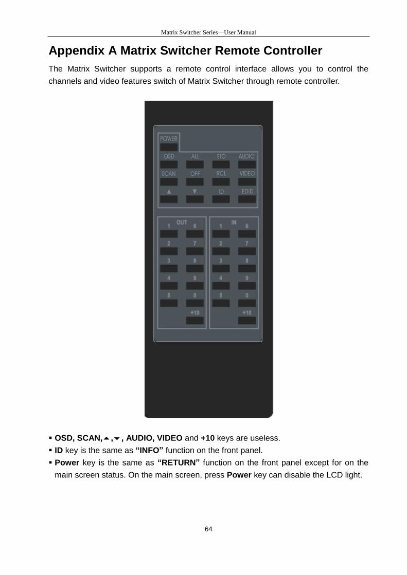
Appendix A Matrix Switcher Remote Controller
The Matrix Switcher supports a remote control interface allows you to control the
channels and video features switch of Matrix Switcher through remote controller.
OSD, SCAN,,, AUDIO, VIDEO and +10 keys are useless.
ID key is the same as “INFO” function on the front panel.
Power key is the same as “RETURN” function on the front panel except for on the
main screen status. On the main screen, press Power key can disable the LCD light.
Matrix Switcher Series—User Manual
65
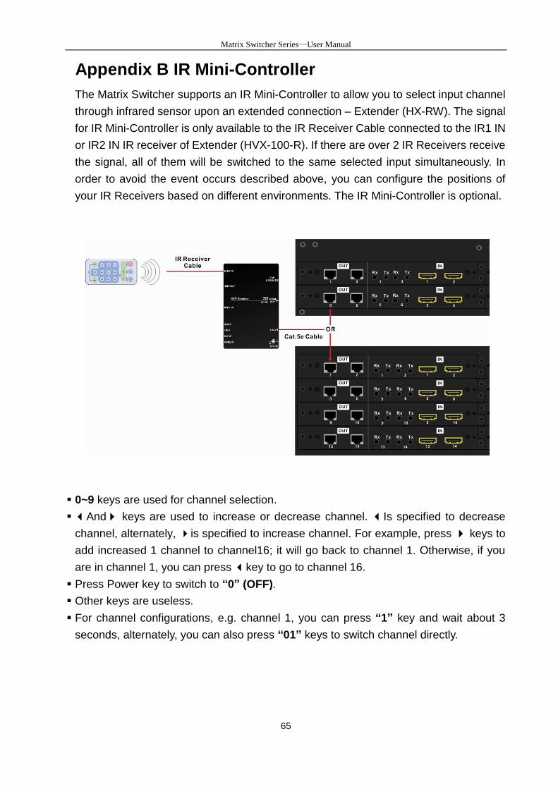
Appendix B IR Mini-Controller
The Matrix Switcher supports an IR Mini-Controller to allow you to select input channel
through infrared sensor upon an extended connection – Extender (HX-RW). The signal
for IR Mini-Controller is only available to the IR Receiver Cable connected to the IR1 IN
or IR2 IN IR receiver of Extender (HVX-100-R). If there are over 2 IR Receivers receive
the signal, all of them will be switched to the same selected input simultaneously. In
order to avoid the event occurs described above, you can configure the positions of
your IR Receivers based on different environments. The IR Mini-Controller is optional.
0~9 keys are used for channel selection.
And keys are used to increase or decrease channel. Is specified to decrease
channel, alternately, is specified to increase channel. For example, press keys to
add increased 1 channel to channel16; it will go back to channel 1. Otherwise, if you
are in channel 1, you can press key to go to channel 16.
Press Power key to switch to “0” (OFF).
Other keys are useless.
For channel configurations, e.g. channel 1, you can press “1” key and wait about 3
seconds, alternately, you can also press “01” keys to switch channel directly.
Matrix Switcher Series—User Manual
66
Appendix C Firmware Upgrade
This Chapter will introduce you how to upgrade firmware on your web browser. For
firmware upgrade, you have to upload the firmware file to your web server and then
upload it to your device from web server.
Follow the steps as below to upgrade the firmware:
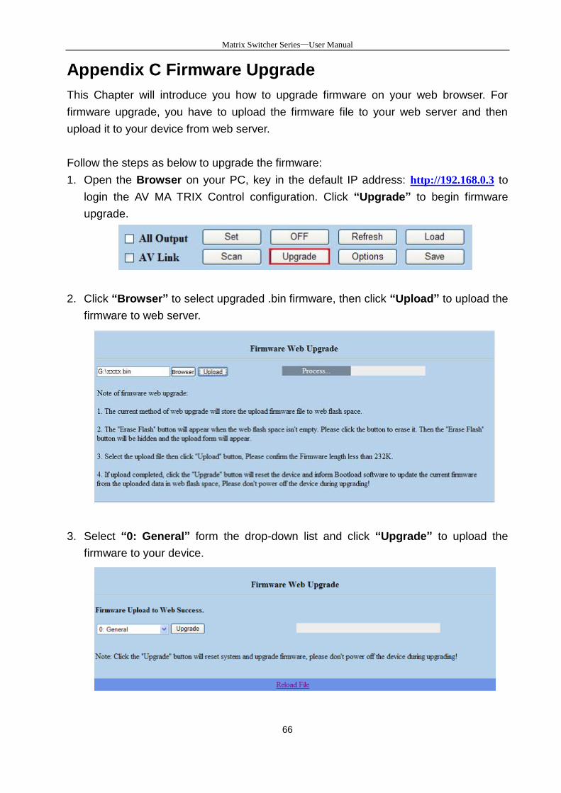
1. Open the Browser on your PC, key in the default IP address: http://192.168.0.3 to
login the AV MA TRIX Control configuration. Click “Upgrade” to begin firmware
upgrade.
2. Click “Browser” to select upgraded .bin firmware, then click “Upload” to upload the
firmware to web server.
3. Select “0: General” form the drop-down list and click “Upgrade” to upload the
firmware to your device.
Matrix Switcher Series—User Manual
67
For 0: General selecting, you have to adjust the switcher ID on the real panel to “0”
that means the device with ID “0” will be upgraded.
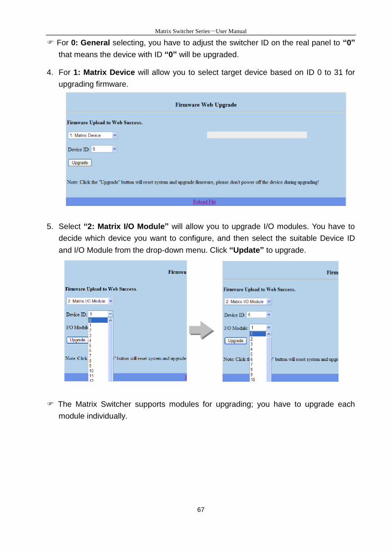
4. For 1: Matrix Device will allow you to select target device based on ID 0 to 31 for
upgrading firmware.
5. Select “2: Matrix I/O Module” will allow you to upgrade I/O modules. You have to
decide which device you want to configure, and then select the suitable Device ID
and I/O Module from the drop-down menu. Click “Update” to upgrade.
The Matrix Switcher supports modules for upgrading; you have to upgrade each
module individually.
Matrix Switcher Series—User Manual
68
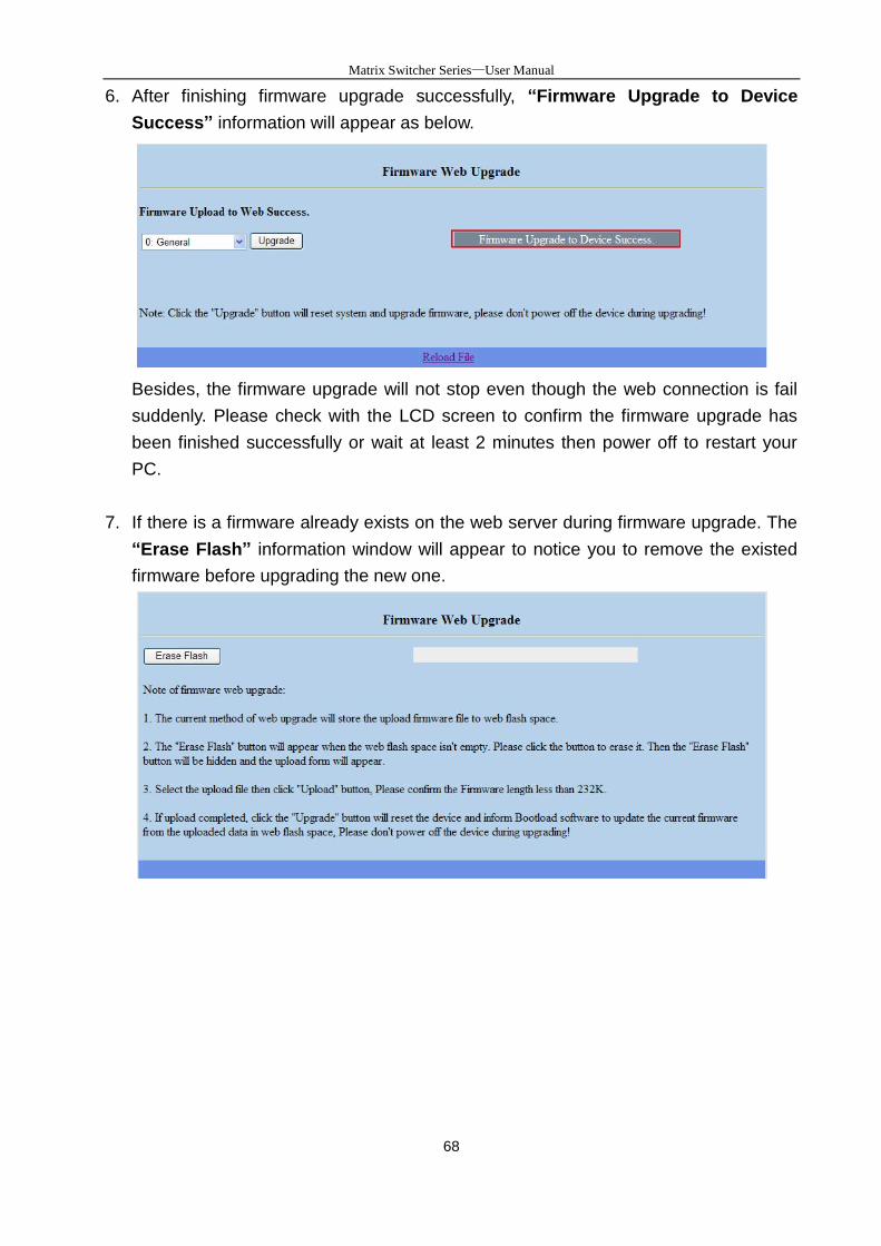
6. After finishing firmware upgrade successfully, “Firmware Upgrade to Device
Success” information will appear as below.
Besides, the firmware upgrade will not stop even though the web connection is fail
suddenly. Please check with the LCD screen to confirm the firmware upgrade has
been finished successfully or wait at least 2 minutes then power off to restart your
PC.
7. If there is a firmware already exists on the web server during firmware upgrade. The
“Erase Flash” information window will appear to notice you to remove the existed
firmware before upgrading the new one.
Matrix Switcher Series—User Manual
69
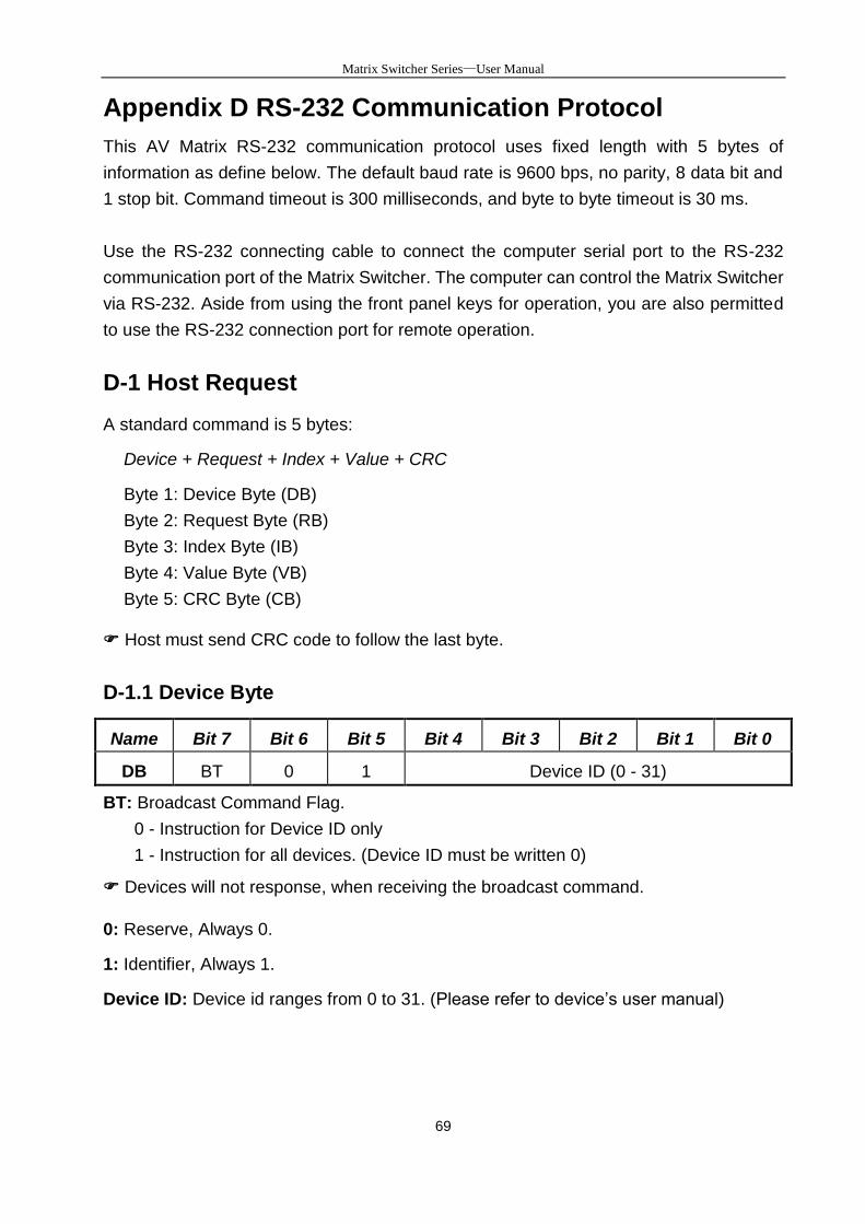
Appendix D RS-232 Communication Protocol
This AV Matrix RS-232 communication protocol uses fixed length with 5 bytes of
information as define below. The default baud rate is 9600 bps, no parity, 8 data bit and
1 stop bit. Command timeout is 300 milliseconds, and byte to byte timeout is 30 ms.
Use the RS-232 connecting cable to connect the computer serial port to the RS-232
communication port of the Matrix Switcher. The computer can control the Matrix Switcher
via RS-232. Aside from using the front panel keys for operation, you are also permitted
to use the RS-232 connection port for remote operation.
D-1 Host Request
A standard command is 5 bytes:
Device + Request + Index + Value + CRC
Byte 1: Device Byte (DB)
Byte 2: Request Byte (RB)
Byte 3: Index Byte (IB)
Byte 4: Value Byte (VB)
Byte 5: CRC Byte (CB)
Host must send CRC code to follow the last byte.
D-1.1 Device Byte
Name Bit 7 Bit 6 Bit 5 Bit 4 Bit 3 Bit 2 Bit 1 Bit 0
DB BT 0 1 Device ID (0 - 31)
BT: Broadcast Command Flag.
0 - Instruction for Device ID only
1 - Instruction for all devices. (Device ID must be written 0)
Devices will not response, when receiving the broadcast command.
0: Reserve, Always 0.
1: Identifier, Always 1.
Device ID: Device id ranges from 0 to 31. (Please refer to device’s user manual)
Matrix Switcher Series—User Manual
70
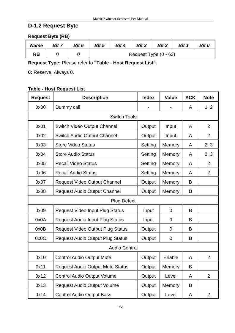
D-1.2 Request Byte
Request Byte (RB)
Name Bit 7 Bit 6 Bit 5 Bit 4 Bit 3 Bit 2 Bit 1 Bit 0
RB 0 0 Request Type (0 - 63)
Request Type: Please refer to "Table - Host Request List".
0: Reserve, Always 0.
Table - Host Request List
Request Description Index Value ACK Note
0x00 Dummy call - - A 1, 2
Switch Tools
0x01 Switch Video Output Channel Output Input A 2
0x02 Switch Audio Output Channel Output Input A 2
0x03 Store Video Status Setting Memory A 2, 3
0x04 Store Audio Status Setting Memory A 2, 3
0x05 Recall Video Status Setting Memory A 2
0x06 Recall Audio Status Setting Memory A 2
0x07 Request Video Output Channel Output Memory B
0x08 Request Audio Output Channel Output Memory B
Plug Detect
0x09 Request Video Input Plug Status Input 0 B
0x0A Request Audio Input Plug Status Input 0 B
0x0B Request Video Output Plug Status Output 0 B
0x0C Request Audio Output Plug Status Output 0 B
Audio Control
0x10 Control Audio Output Mute Output Enable A 2
0x11 Request Audio Output Mute Status Output Memory B
0x12 Control Audio Output Volume Output Level A 2
0x13 Request Audio Output Volume Output Memory B
0x14 Control Audio Output Bass Output Level A 2
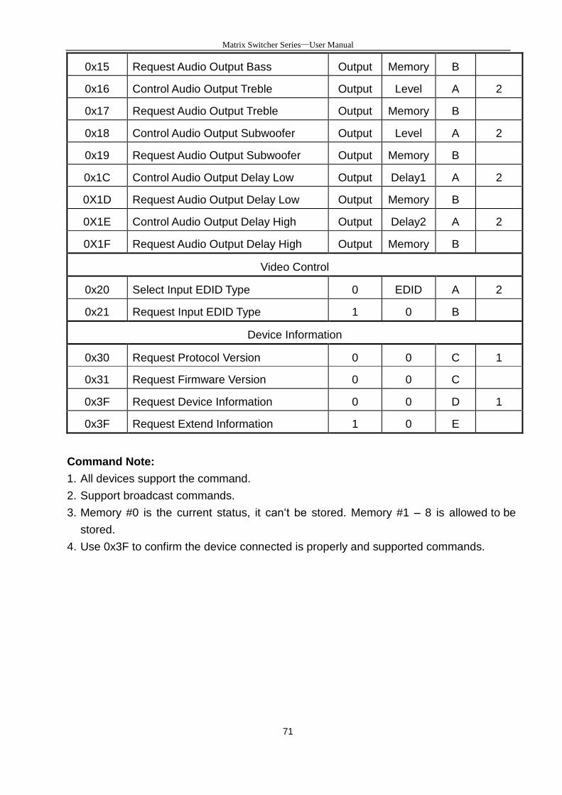
Matrix Switcher Series—User Manual
71
0x15 Request Audio Output Bass Output Memory B
0x16 Control Audio Output Treble Output Level A 2
0x17 Request Audio Output Treble Output Memory B
0x18 Control Audio Output Subwoofer Output Level A 2
0x19 Request Audio Output Subwoofer Output Memory B
0x1C Control Audio Output Delay Low Output Delay1 A 2
0X1D Request Audio Output Delay Low Output Memory B
0X1E Control Audio Output Delay High Output Delay2 A 2
0X1F Request Audio Output Delay High Output Memory B
Video Control
0x20 Select Input EDID Type 0 EDID A 2
0x21 Request Input EDID Type 1 0 B
Device Information
0x30 Request Protocol Version 0 0 C 1
0x31 Request Firmware Version 0 0 C
0x3F Request Device Information 0 0 D 1
0x3F Request Extend Information 1 0 E
Command Note:
1. All devices support the command.
2. Support broadcast commands.
3. Memory #0 is the current status, it can‘t be stored. Memory #1 – 8 is allowed to be
stored.
4. Use 0x3F to confirm the device connected is properly and supported commands.

Matrix Switcher Series—User Manual
72
D-1.3 Index Byte
Index Byte (IB)
Name Bit 7 Bit 6 Bit 5 Bit 4 Bit 3 Bit 2 Bit 1 Bit 0
IB Index
Index: Please refer to "Table - Host Request List" and "Table - Command Index List".
Table – Command Index List
Index Description
Output The output that will be selected. (Port 1 = 1, Port 2 = 2… Port n = n)
0: All outputs
Input The input that will be selected. (Port 1 = 1, Port 2 = 2… Port n = n)
0: All inputs
Setting
The setting type that will be selected.
0: All Settings
1: Switch Settings only
2: Video/Audio Settings only
- Don’t care
Matrix Switcher Series—User Manual
73
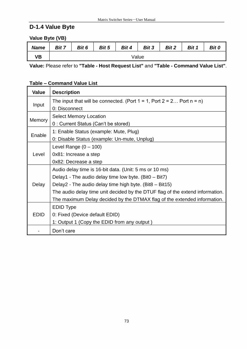
D-1.4 Value Byte
Value Byte (VB)
Name Bit 7 Bit 6 Bit 5 Bit 4 Bit 3 Bit 2 Bit 1 Bit 0
VB Value
Value: Please refer to "Table - Host Request List" and "Table - Command Value List".
Table – Command Value List
Value Description
Input The input that will be connected. (Port 1 = 1, Port 2 = 2… Port n = n)
0: Disconnect
Memory Select Memory Location
0 : Current Status (Can‘t be stored)
Enable 1: Enable Status (example: Mute, Plug)
0: Disable Status (example: Un-mute, Unplug)
Level
Level Range (0 – 100)
0x81: Increase a step
0x82: Decrease a step
Delay
Audio delay time is 16-bit data. (Unit: 5 ms or 10 ms)
Delay1 - The audio delay time low byte. (Bit0 – Bit7)
Delay2 - The audio delay time high byte. (Bit8 – Bit15)
The audio delay time unit decided by the DTUF flag of the extend information.
The maximum Delay decided by the DTMAX flag of the extended information.
EDID
EDID Type
0: Fixed (Device default EDID)
1: Output 1 (Copy the EDID from any output )
- Don’t care
Matrix Switcher Series—User Manual
74
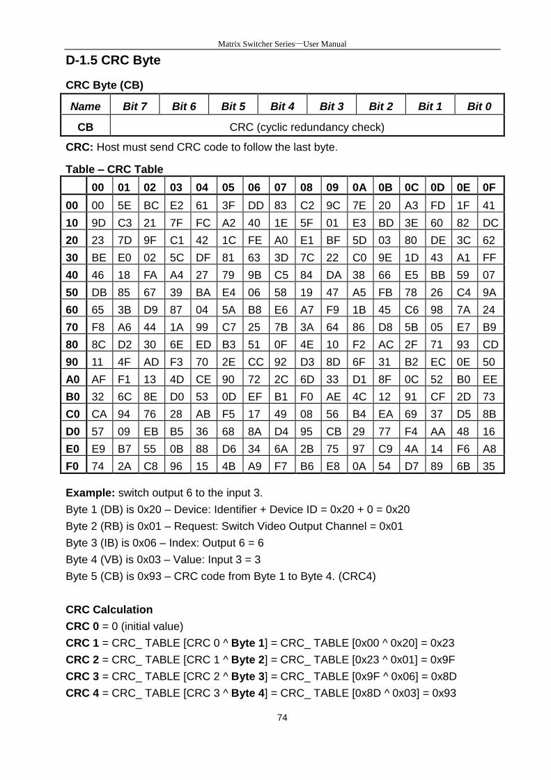
D-1.5 CRC Byte
CRC Byte (CB)
Name Bit 7 Bit 6 Bit 5 Bit 4 Bit 3 Bit 2 Bit 1 Bit 0
CB CRC (cyclic redundancy check)
CRC: Host must send CRC code to follow the last byte.
Table – CRC Table
00 01 02 03 04 05 06 07 08 09 0A 0B 0C 0D 0E 0F
00 00 5E BC E2 61 3F DD 83 C2 9C 7E 20 A3 FD 1F 41
10 9D C3 21 7F FC A2 40 1E 5F 01 E3 BD 3E 60 82 DC
20 23 7D 9F C1 42 1C FE A0 E1 BF 5D 03 80 DE 3C 62
30 BE E0 02 5C DF 81 63 3D 7C 22 C0 9E 1D 43 A1 FF
40 46 18 FA A4 27 79 9B C5 84 DA 38 66 E5 BB 59 07
50 DB 85 67 39 BA E4 06 58 19 47 A5 FB 78 26 C4 9A
60 65 3B D9 87 04 5A B8 E6 A7 F9 1B 45 C6 98 7A 24
70 F8 A6 44 1A 99 C7 25 7B 3A 64 86 D8 5B 05 E7 B9
80 8C D2 30 6E ED B3 51 0F 4E 10 F2 AC 2F 71 93 CD
90 11 4F AD F3 70 2E CC 92 D3 8D 6F 31 B2 EC 0E 50
A0 AF F1 13 4D CE 90 72 2C 6D 33 D1 8F 0C 52 B0 EE
B0 32 6C 8E D0 53 0D EF B1 F0 AE 4C 12 91 CF 2D 73
C0 CA 94 76 28 AB F5 17 49 08 56 B4 EA 69 37 D5 8B
D0 57 09 EB B5 36 68 8A D4 95 CB 29 77 F4 AA 48 16
E0 E9 B7 55 0B 88 D6 34 6A 2B 75 97 C9 4A 14 F6 A8
F0 74 2A C8 96 15 4B A9 F7 B6 E8 0A 54 D7 89 6B 35
Example: switch output 6 to the input 3.
Byte 1 (DB) is 0x20 – Device: Identifier + Device ID = 0x20 + 0 = 0x20
Byte 2 (RB) is 0x01 – Request: Switch Video Output Channel = 0x01
Byte 3 (IB) is 0x06 – Index: Output 6 = 6
Byte 4 (VB) is 0x03 – Value: Input 3 = 3
Byte 5 (CB) is 0x93 – CRC code from Byte 1 to Byte 4. (CRC4)
CRC Calculation
CRC 0 = 0 (initial value)
CRC 1 = CRC_ TABLE [CRC 0 ^ Byte 1] = CRC_ TABLE [0x00 ^ 0x20] = 0x23
CRC 2 = CRC_ TABLE [CRC 1 ^ Byte 2] = CRC_ TABLE [0x23 ^ 0x01] = 0x9F
CRC 3 = CRC_ TABLE [CRC 2 ^ Byte 3] = CRC_ TABLE [0x9F ^ 0x06] = 0x8D
CRC 4 = CRC_ TABLE [CRC 3 ^ Byte 4] = CRC_ TABLE [0x8D ^ 0x03] = 0x93
Matrix Switcher Series—User Manual
75
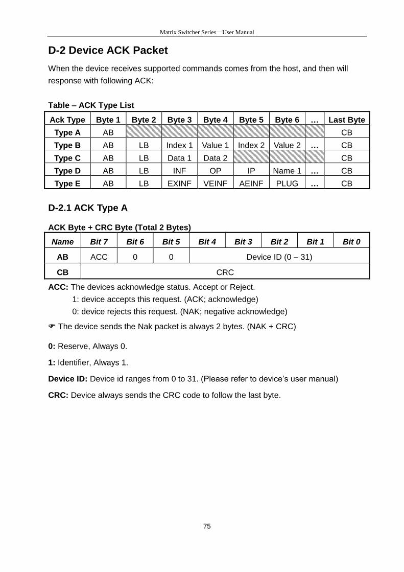
D-2 Device ACK Packet
When the device receives supported commands comes from the host, and then will
response with following ACK:
Table – ACK Type List
Ack Type Byte 1 Byte 2 Byte 3 Byte 4 Byte 5 Byte 6 … Last Byte
Type A AB CB
Type B AB LB Index 1 Value 1 Index 2 Value 2 … CB
Type C AB LB Data 1 Data 2 CB
Type D AB LB INF OP IP Name 1 … CB
Type E AB LB EXINF VEINF AEINF PLUG … CB
D-2.1 ACK Type A
ACK Byte + CRC Byte (Total 2 Bytes)
Name Bit 7 Bit 6 Bit 5 Bit 4 Bit 3 Bit 2 Bit 1 Bit 0
AB ACC 0 0 Device ID (0 – 31)
CB CRC
ACC: The devices acknowledge status. Accept or Reject.
1: device accepts this request. (ACK; acknowledge)
0: device rejects this request. (NAK; negative acknowledge)
The device sends the Nak packet is always 2 bytes. (NAK + CRC)
0: Reserve, Always 0.
1: Identifier, Always 1.
Device ID: Device id ranges from 0 to 31. (Please refer to device’s user manual)
CRC: Device always sends the CRC code to follow the last byte.
Matrix Switcher Series—User Manual
76
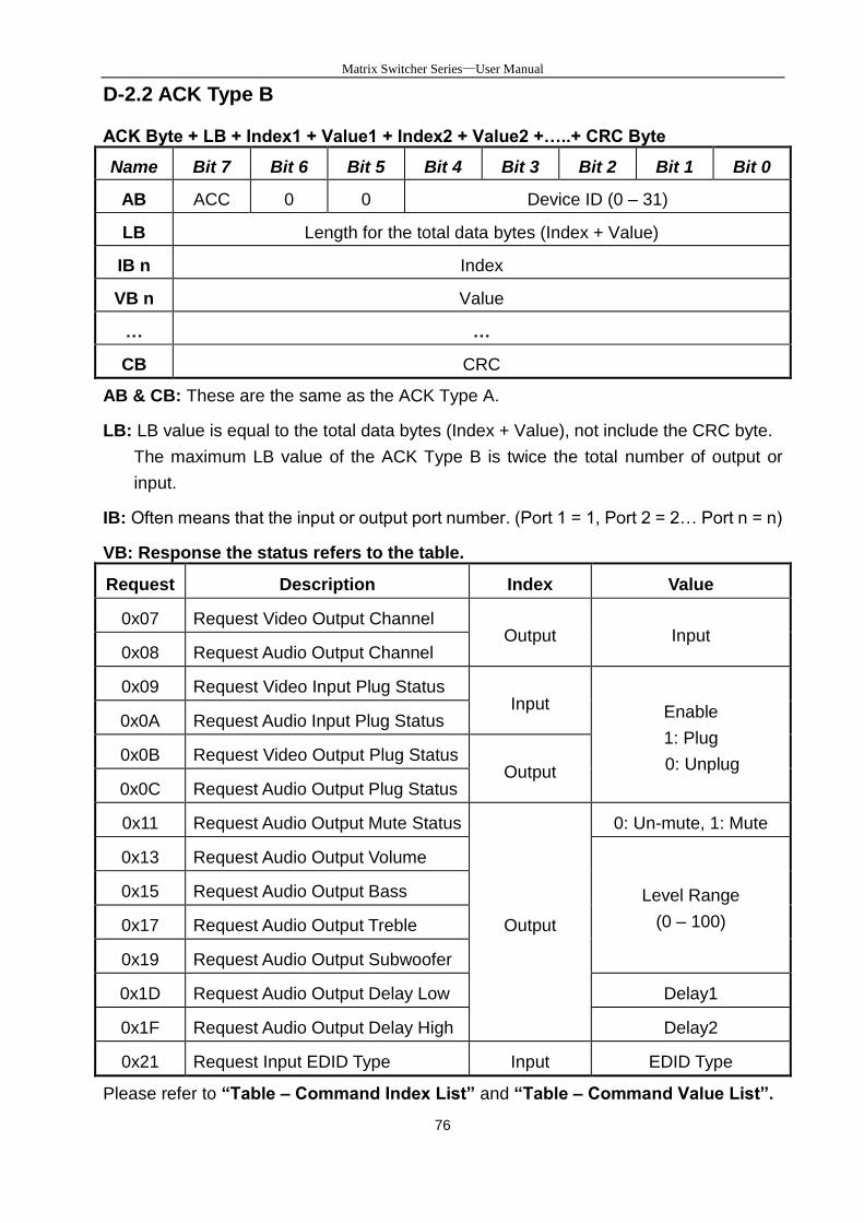
D-2.2 ACK Type B
ACK Byte + LB + Index1 + Value1 + Index2 + Value2 +…..+ CRC Byte
Name Bit 7 Bit 6 Bit 5 Bit 4 Bit 3 Bit 2 Bit 1 Bit 0
AB ACC 0 0 Device ID (0 – 31)
LB Length for the total data bytes (Index + Value)
IB n Index
VB n Value
… …
CB CRC
AB & CB: These are the same as the ACK Type A.
LB: LB value is equal to the total data bytes (Index + Value), not include the CRC byte.
The maximum LB value of the ACK Type B is twice the total number of output or
input.
IB: Often means that the input or output port number. (Port 1 = 1, Port 2 = 2… Port n = n)
VB: Response the status refers to the table.
Request Description Index Value
0x07 Request Video Output Channel Output Input
0x08 Request Audio Output Channel
0x09 Request Video Input Plug Status Input Enable
1: Plug
0: Unplug
0x0A Request Audio Input Plug Status
0x0B Request Video Output Plug Status Output
0x0C Request Audio Output Plug Status
0x11 Request Audio Output Mute Status
Output
0: Un-mute, 1: Mute
0x13 Request Audio Output Volume
Level Range
(0 – 100)
0x15 Request Audio Output Bass
0x17 Request Audio Output Treble
0x19 Request Audio Output Subwoofer
0x1D Request Audio Output Delay Low Delay1
0x1F Request Audio Output Delay High Delay2
0x21 Request Input EDID Type Input EDID Type
Please refer to “Table – Command Index List” and “Table – Command Value List”.
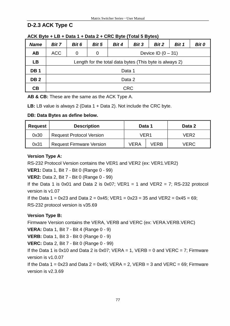
Matrix Switcher Series—User Manual
77
D-2.3 ACK Type C
ACK Byte + LB + Data 1 + Data 2 + CRC Byte (Total 5 Bytes)
Name Bit 7 Bit 6 Bit 5 Bit 4 Bit 3 Bit 2 Bit 1 Bit 0
AB ACC 0 0 Device ID (0 – 31)
LB Length for the total data bytes (This byte is always 2)
DB 1 Data 1
DB 2 Data 2
CB CRC
AB & CB: These are the same as the ACK Type A.
LB: LB value is always 2 (Data 1 + Data 2). Not include the CRC byte.
DB: Data Bytes as define below.
Request Description Data 1 Data 2
0x30 Request Protocol Version VER1 VER2
0x31 Request Firmware Version VERA VERB VERC
Version Type A:
RS-232 Protocol Version contains the VER1 and VER2 (ex: VER1.VER2)
VER1: Data 1, Bit 7 - Bit 0 (Range 0 - 99)
VER2: Data 2, Bit 7 - Bit 0 (Range 0 - 99)
If the Data 1 is 0x01 and Data 2 is 0x07; VER1 = 1 and VER2 = 7; RS-232 protocol
version is v1.07
If the Data 1 = 0x23 and Data 2 = 0x45; VER1 = 0x23 = 35 and VER2 = 0x45 = 69;
RS-232 protocol version is v35.69
Version Type B:
Firmware Version contains the VERA, VERB and VERC (ex: VERA.VERB.VERC)
VERA: Data 1, Bit 7 - Bit 4 (Range 0 - 9)
VERB: Data 1, Bit 3 - Bit 0 (Range 0 - 9)
VERC: Data 2, Bit 7 - Bit 0 (Range 0 - 99)
If the Data 1 is 0x10 and Data 2 is 0x07; VERA = 1, VERB = 0 and VERC = 7; Firmware
version is v1.0.07
If the Data 1 = 0x23 and Data 2 = 0x45; VERA = 2, VERB = 3 and VERC = 69; Firmware
version is v2.3.69
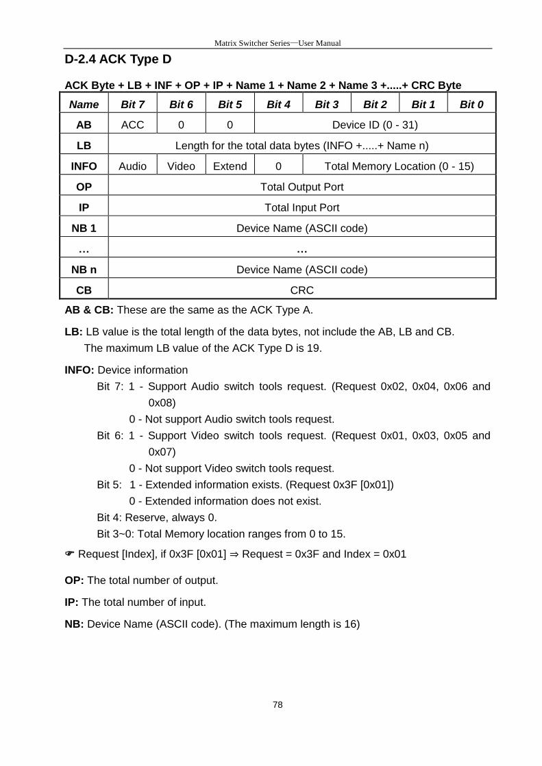
Matrix Switcher Series—User Manual
78
D-2.4 ACK Type D
ACK Byte + LB + INF + OP + IP + Name 1 + Name 2 + Name 3 +.....+ CRC Byte
Name Bit 7 Bit 6 Bit 5 Bit 4 Bit 3 Bit 2 Bit 1 Bit 0
AB ACC 0 0 Device ID (0 - 31)
LB Length for the total data bytes (INFO +.....+ Name n)
INFO Audio Video Extend 0 Total Memory Location (0 - 15)
OP Total Output Port
IP Total Input Port
NB 1 Device Name (ASCII code)
… …
NB n Device Name (ASCII code)
CB CRC
AB & CB: These are the same as the ACK Type A.
LB: LB value is the total length of the data bytes, not include the AB, LB and CB.
The maximum LB value of the ACK Type D is 19.
INFO: Device information
Bit 7: 1 - Support Audio switch tools request. (Request 0x02, 0x04, 0x06 and
0x08)
0 - Not support Audio switch tools request.
Bit 6: 1 - Support Video switch tools request. (Request 0x01, 0x03, 0x05 and
0x07)
0 - Not support Video switch tools request.
Bit 5: 1 - Extended information exists. (Request 0x3F [0x01])
0 - Extended information does not exist.
Bit 4: Reserve, always 0.
Bit 3~0: Total Memory location ranges from 0 to 15.
Request [Index], if 0x3F [0x01] ⇒ Request = 0x3F and Index = 0x01
OP: The total number of output.
IP: The total number of input.
NB: Device Name (ASCII code). (The maximum length is 16)
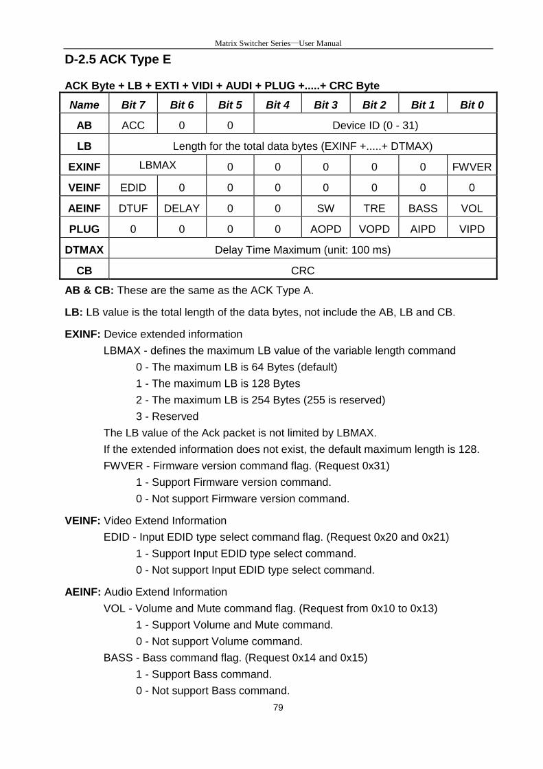
Matrix Switcher Series—User Manual
79
D-2.5 ACK Type E
ACK Byte + LB + EXTI + VIDI + AUDI + PLUG +.....+ CRC Byte
Name Bit 7 Bit 6 Bit 5 Bit 4 Bit 3 Bit 2 Bit 1 Bit 0
AB ACC 0 0 Device ID (0 - 31)
LB Length for the total data bytes (EXINF +.....+ DTMAX)
EXINF LBMAX
0
0 0 0 0 0 FWVER
VEINF EDID 0 0 0 0 0 0 0
AEINF DTUF DELAY 0 0 SW TRE BASS VOL
PLUG 0 0 0 0 AOPD VOPD AIPD VIPD
DTMAX Delay Time Maximum (unit: 100 ms)
CB CRC
AB & CB: These are the same as the ACK Type A.
LB: LB value is the total length of the data bytes, not include the AB, LB and CB.
EXINF: Device extended information
LBMAX - defines the maximum LB value of the variable length command
0 - The maximum LB is 64 Bytes (default)
1 - The maximum LB is 128 Bytes
2 - The maximum LB is 254 Bytes (255 is reserved)
3 - Reserved
The LB value of the Ack packet is not limited by LBMAX.
If the extended information does not exist, the default maximum length is 128.
FWVER - Firmware version command flag. (Request 0x31)
1 - Support Firmware version command.
0 - Not support Firmware version command.
VEINF: Video Extend Information
EDID - Input EDID type select command flag. (Request 0x20 and 0x21)
1 - Support Input EDID type select command.
0 - Not support Input EDID type select command.
AEINF: Audio Extend Information
VOL - Volume and Mute command flag. (Request from 0x10 to 0x13)
1 - Support Volume and Mute command.
0 - Not support Volume command.
BASS - Bass command flag. (Request 0x14 and 0x15)
1 - Support Bass command.
0 - Not support Bass command.
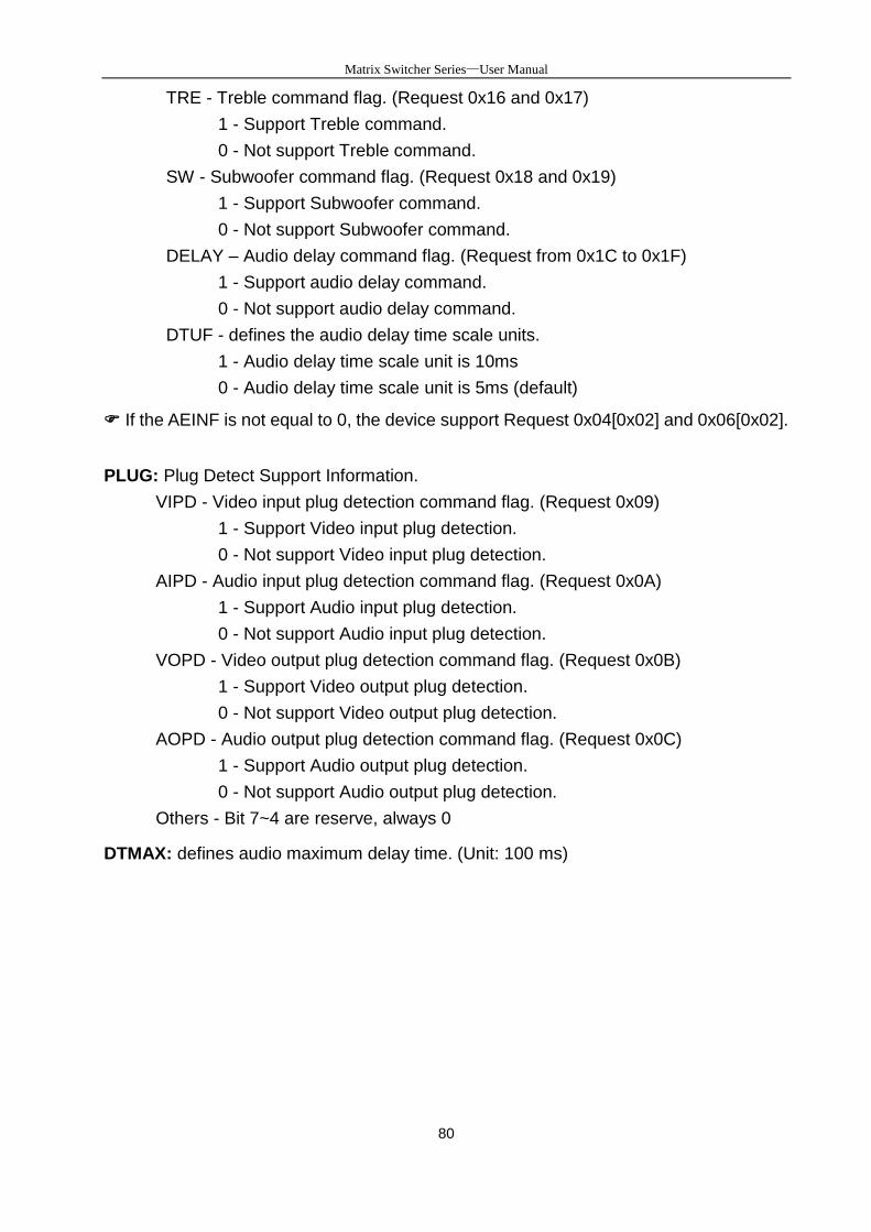
Matrix Switcher Series—User Manual
80
TRE - Treble command flag. (Request 0x16 and 0x17)
1 - Support Treble command.
0 - Not support Treble command.
SW - Subwoofer command flag. (Request 0x18 and 0x19)
1 - Support Subwoofer command.
0 - Not support Subwoofer command.
DELAY – Audio delay command flag. (Request from 0x1C to 0x1F)
1 - Support audio delay command.
0 - Not support audio delay command.
DTUF - defines the audio delay time scale units.
1 - Audio delay time scale unit is 10ms
0 - Audio delay time scale unit is 5ms (default)
If the AEINF is not equal to 0, the device support Request 0x04[0x02] and 0x06[0x02].
PLUG: Plug Detect Support Information.
VIPD - Video input plug detection command flag. (Request 0x09)
1 - Support Video input plug detection.
0 - Not support Video input plug detection.
AIPD - Audio input plug detection command flag. (Request 0x0A)
1 - Support Audio input plug detection.
0 - Not support Audio input plug detection.
VOPD - Video output plug detection command flag. (Request 0x0B)
1 - Support Video output plug detection.
0 - Not support Video output plug detection.
AOPD - Audio output plug detection command flag. (Request 0x0C)
1 - Support Audio output plug detection.
0 - Not support Audio output plug detection.
Others - Bit 7~4 are reserve, always 0
DTMAX: defines audio maximum delay time. (Unit: 100 ms)

Matrix Switcher Series—User Manual
81
Appendix E Extender (HVX-100-R)
The extension of HDMI video signal device supports up to 100 meter away by using an
Extender and Cat.5e cable.
HDMI Extender is ideal for:
Test bench facilities
Data Center
Help desks
Front View
Rear View
LED Indicators (Green):
LED Off Blink On
POWER Power Off - Power On
MODE - Power Connected -
LINK No Link Low Power Mode HDBaseT Link
HDCP No HDMI Signals No Encryption HDCP Encryption
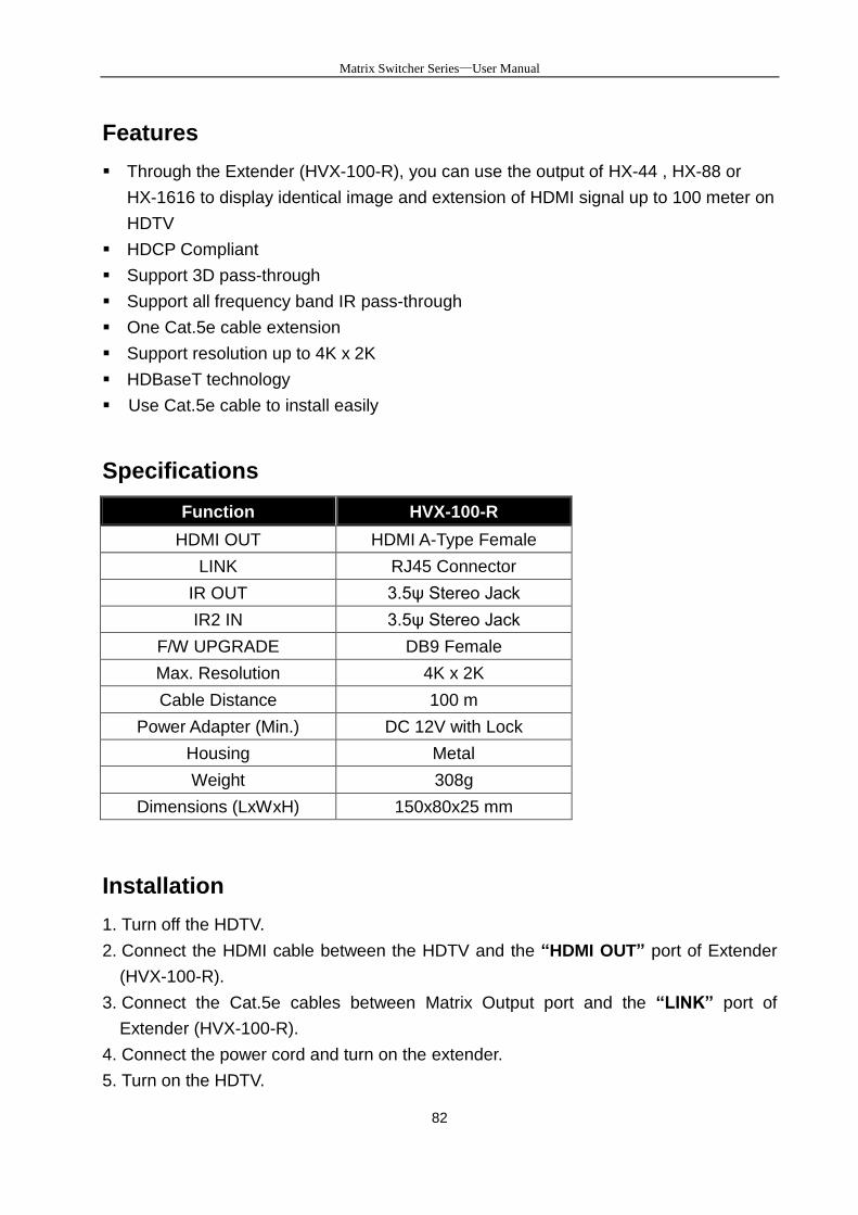
Matrix Switcher Series—User Manual
82
Features
Through the Extender (HVX-100-R), you can use the output of HX-44 , HX-88 or
HX-1616 to display identical image and extension of HDMI signal up to 100 meter on
HDTV
HDCP Compliant
Support 3D pass-through
Support all frequency band IR pass-through
One Cat.5e cable extension
Support resolution up to 4K x 2K
HDBaseT technology
Use Cat.5e cable to install easily
Specifications
Function HVX-100-R
HDMI OUT HDMI A-Type Female
LINK RJ45 Connector
IR OUT 3.5ψ Stereo Jack
IR2 IN 3.5ψ Stereo Jack
F/W UPGRADE DB9 Female
Max. Resolution 4K x 2K
Cable Distance 100 m
Power Adapter (Min.) DC 12V with Lock
Housing Metal
Weight 308g
Dimensions (LxWxH) 150x80x25 mm
Installation
1. Turn off the HDTV.
2. Connect the HDMI cable between the HDTV and the “HDMI OUT” port of Extender
(HVX-100-R).
3. Connect the Cat.5e cables between Matrix Output port and the “LINK” port of
Extender (HVX-100-R).
4. Connect the power cord and turn on the extender.
5. Turn on the HDTV.

Matrix Switcher Series—User Manual
83

Matrix Switching System—User Manual
84
IR Receiver Cable Directions
Put IR Receiver Cable into the Extender (HX-RW) “IR2 IN” port and place the IR
Receiver Cable, so that you can point to it easily with your IR remote controller.
IR Receiver Cable:
GND+VSig
IR Blaster Cable Directions
Plug IR Blaster Cable into Extender (HX-RW) “IR OUT” port located on the front-panel.
IR Emitter:
HDMI Output Connector
Pin # Signal Pin # Signal
1 TMDS Data 2+ 11 TMDS Clock Shield
2 TMDS Data 2 Shield 12 TMDS Clock -
3 TMDS Data 2- 13 CEC
4 TMDS Data 1+ 14 Utility (NC on device)
5 TMDS Data 1 Shield 15 DDC SCL
6 TMDS Data 1- 16 DDC SDA
7 TMDS Data 0+ 17 DDC/CEC Ground
8 TMDS Data 0 Shield 18 +5 Power
9 TMDS Data 0- 19 Hot Plug Detect
10 TMDS Clock+
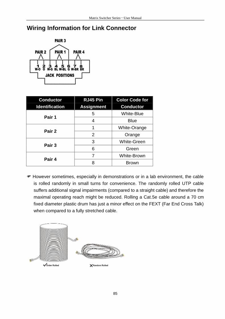
Matrix Switcher Series—User Manual
85
Wiring Information for Link Connector
Conductor
Identification
RJ45 Pin
Assignment
Color Code for
Conductor
Pair 1 5 White-Blue
4 Blue
Pair 2 1 White-Orange
2 Orange
Pair 3 3 White-Green
6 Green
Pair 4 7 White-Brown
8 Brown
However sometimes, especially in demonstrations or in a lab environment, the cable
is rolled randomly in small turns for convenience. The randomly rolled UTP cable
suffers additional signal impairments (compared to a straight cable) and therefore the
maximal operating reach might be reduced. Rolling a Cat.5e cable around a 70 cm
fixed diameter plastic drum has just a minor effect on the FEXT (Far End Cross Talk)
when compared to a fully stretched cable.
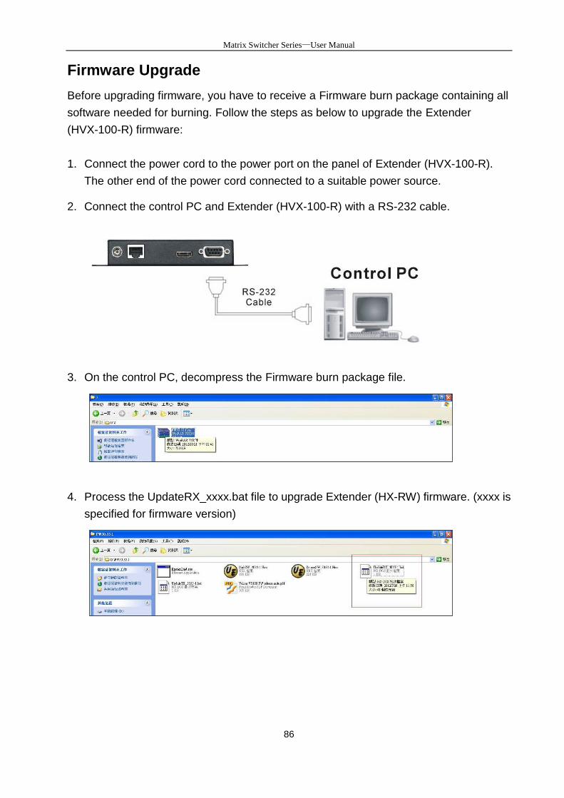
Matrix Switcher Series—User Manual
86
Firmware Upgrade
Before upgrading firmware, you have to receive a Firmware burn package containing all
software needed for burning. Follow the steps as below to upgrade the Extender
(HVX-100-R) firmware:
1. Connect the power cord to the power port on the panel of Extender (HVX-100-R).
The other end of the power cord connected to a suitable power source.
2. Connect the control PC and Extender (HVX-100-R) with a RS-232 cable.
3. On the control PC, decompress the Firmware burn package file.
4. Process the UpdateRX_xxxx.bat file to upgrade Extender (HX-RW) firmware. (xxxx is
specified for firmware version)
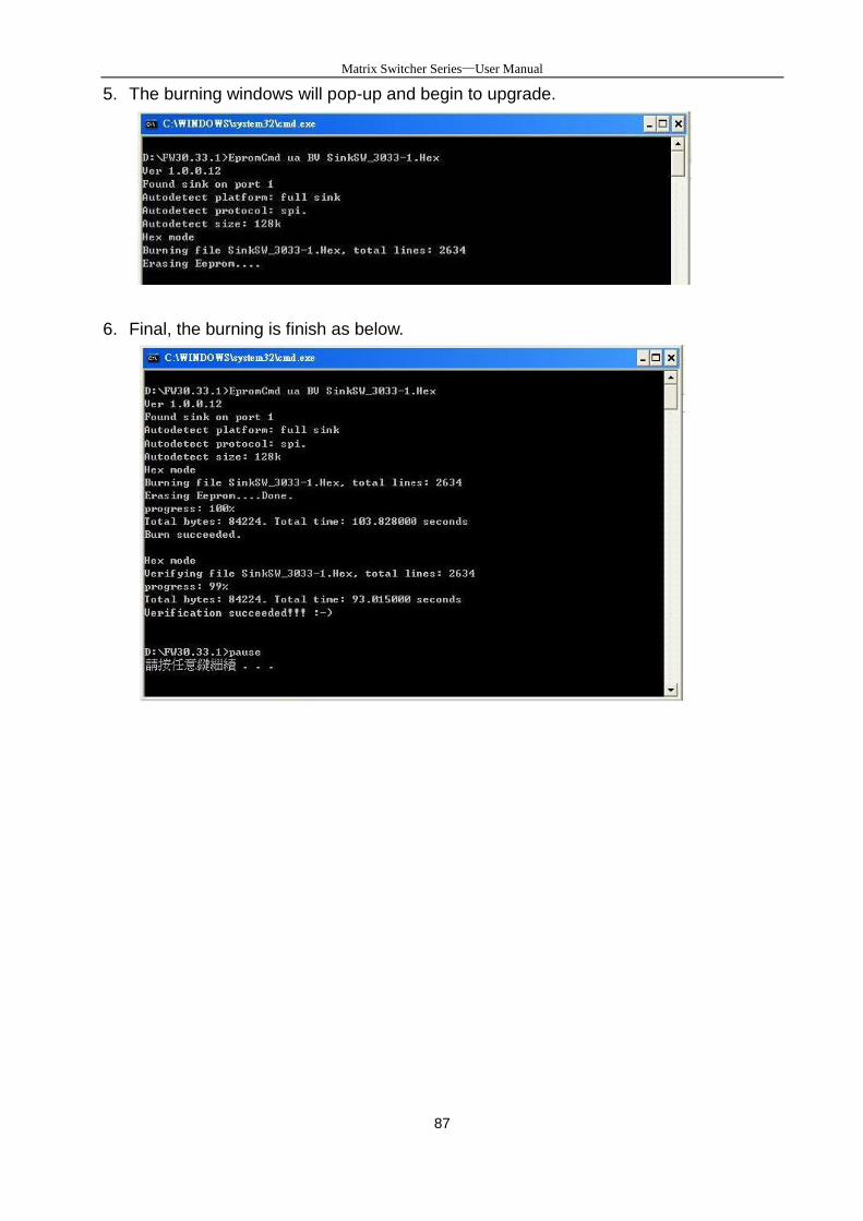
Matrix Switcher Series—User Manual
87
5. The burning windows will pop-up and begin to upgrade.
6. Final, the burning is finish as below.