Embed Size (px)
Citation preview
Dispersion of entropy waves advecting through combustion chambers
UKCTRF Annual Meeting
15th September 2016, Durham University, Durham
Yu Xia, Ignacio Duran, Aimee S. Morgans, Xingsi Han
Department of Mechanical Engineering,
Imperial College London, U.K.

Outline
1. Motivation
–– Entropy wave and entropy noise
2. Methodology
–– Passive scalar entropy transport + flowfield LES
3. Result
–– Entropy wave advection in turbulent reacting flows
4. Conclusion & Future Work
2

1.1. Generation of entropy waves
Entropy waves are temperature fluctuations (𝑇′) generated by unsteady
combustion in a gas turbine combustor, also known as “hot/cold spots”.
Flame image courtesy
of R. Balachandran
Unsteady flame
Entropy waves
(𝑝′)
3
Hot spots
Cold spots
Entropy waves (𝑇′)

1.2. Entropy wave advection and release of entropy noise
The generated entropy waves are swept downstream by the mean flow, advecting
towards the chamber exit, accelerating through the nozzle or turbine blades and
releasing “entropy noise*” (also known as “indirect combustion noise”).
Entropy wave
acceleration
in turbine stages
Entropy wave
acceleration
in a supersonic
nozzle
4
* Marble & Candel. 1977

1.3. Impact of entropy noise on gas turbine performance
• The released entropy noise are transmitted further downstream, increasing the
total noise level from gas turbine, and also reflected upstream and interact with
the flame, contributing to the damaging thermoaocustic instabilities.
* Leyko et al. 2009Schematics of flow perturbations in a gas turbine combustor
Contributes to thermoacoustic instability Increasing total noise level
• The strength of entropy noise is proportional to the entropy wave amplitude at
the combustor exit, which is an order of magnitude larger* than the direct
acoustic noise generated by the flame.
5
exit

1.4. Entropy wave dispersion in fully-developed pipe flow
• Traditional low-order models* for entropy noise neglect entropy wave advection and
assume uniform amplitude at exit plane, but entropy wave advection can be dispersive
and attenuate the exiting entropy amplitude and affect the generated entropy noise.
• E.g. in a fully-developed pipe flow**, the PDF of the residence time 𝜏𝑟 from flame to
pipe exit follows a Gaussian distribution, with highly-decreased entropy wave amplitude
at pipe exit. This is due to the dispersion effect of the non-uniform velocity profile 𝑢(𝑟).
* Marble & Candel. 1977 ** Morgans et al, JFM, 2013
𝜏𝑟 =𝐿
𝑢(𝑟)
Pipe length L
𝑢(𝑟)Flame
Exit
PDF of 𝜏𝑟
6

1.5. Aim of this work
Photo of the test combustor, taken from a Siemens
SGT-100 gas turbine (Stopper 2013)
Sketch of the combustion chamber,
Indicating flow swirling and CH4/air premixing
• Different from a fully-developed pipe flow, the turbulent reacting flow in a gas turbine
combustor is much more complex (e.g. vortex shedding, flow swirling), which is expected to
have higher dispersion effects on entropy wave advection.
• In this work, the entropy wave advection in a full-scale industrial combustor is studied,
operated under lean premixed condition at 3 bar pressure, with cold gaseous methane (CH4)
premixed with hot preheated air.
7

2.1. Entropy wave equation
The governing equation for entropy wave within a fluid flow is:
Entropy advection Heat addition Thermal gradients Frictional heating
The non-dimensional version of above equation is then obtained:
For a turbulent reacting flow with low bulk Ma number and large bulk Re number ,
the entropy wave equation simplifies into a purely entropy advection equation:
8

2.2. Large eddy simulation (LES) of turbulent reacting flow
The open-source low-Mach LES code OpenFOAM is used to simulate turbulent
reacting flows in this combustor.
The computational domain* contains 8.5m
structured mesh cells with flame refined.
• 1st-order (Euler) time discretisation + 2nd-order (Gaussian) spatial discretisation;
• Smagorinsky model for sub-grid scale turbulent modelling, and Partially-Stirred Reactor
(PaSR) model for turbulence-chemistry interaction;
• 4-step reduced mechanism for methane/air reaction, involving 7 intermediate species (incl.
CH4, CO, CO2, H2, H2O, O2, N2).
Numerical settings
Contour of mean heat release rate per unit
volume on symmetry plane Y=0
9
* G. Bulat. 2012

2.2. Large eddy simulation (LES) of turbulent reacting flow
The mean and an instantaneous flowfield are both simulated. A flow recirculation zone
exists in both flowfields, but the instantaneous flowfield also exhibits large-scale
unsteady flow structures (e.g. swirl), which are not captured in the mean flowfield.
“Time-frozen” mean
flowfield
“Time-varying”
instantaneous
flowfield
Flow recirculation
zone
Large-scale
unsteady flow
structures
10

2.3. Passive scalar entropy transport method
A Gaussian-type impulsive entropy source 𝑄 is defined at the mean flame location based on
the mean heat release field 𝑞𝑚𝑒𝑎𝑛, introducing passive scalar entropy into the combustor.
Entropy source 𝑸 at mean
flame location
Gaussian shape function:
(𝑡1 = 0.005 𝑠 , 𝜎1 = 0.001 𝑠)
Time-variation of entropy source 𝑸
Now the pure entropy advection equation has a source term 𝑄 on its right-hand side:
where
11

With the impulsive entropy source 𝑄, the entropy advection equation becomes a
passive scalar transport equation:
The entropy 𝑠 is a
passive scalar
which advects within the
mean velocity field from flame location to
combustor chamber exit
For an instantaneous flowfield, 𝑢𝑚𝑒𝑎𝑛 is replaced by instantaneous vector 𝑢𝑖𝑛𝑠:
2.3. Passive scalar entropy transport method
𝑢𝑖𝑛𝑠
Above two key equations are then simulated for entropy wave advection
in a turbulent premixed combustor.
12

3.1. Entropy advection within “time-frozen” mean flowfield
13
In the “time-frozen” mean flowfield, entropy waves close to the side-walls reach the
chamber exit earlier, but near the centreline the waves are drawn upstream by
flow recirculation zone and trapped inside it for a long time.
“Time-frozen” mean
flowfield
on plane Y=0
Entropy wave advection
on plane Y=0

3.1. Entropy advection within “time-frozen” mean flowfield
Entropy wave advection within the “time-frozen” mean flowfield
It takes a long time (~0.2s) for all the
entropy waves to exit the chamber, due to
the “dragging & trapping” effects of the
flow recirculation zone near centreline.
1
3× source amplitude
Short tail
Entropy source
Entropy wave at exit
The entropy wave amplitude at chamber
exit follows the Gaussian shape, and
remains 1/3 of the source amplitude due to
the non-uniform mean velocity profile.
Entropy remaining
in the chamber
Entropy already
left the chamber
14

3.2. Entropy advection within “time-varying” instantaneous flowfield
15
In a “time-varying” instantaneous flowfield, entropy wave advection is irregular and
faster due to large-scale unsteady flow features increasing the downstream speed.
The effect of the centreline flow recirculation zone is much weaker and negligible.
“Time-varying’’
instantaneous flow field
on plane Y=0
Entropy wave advection
on plane Y=0

Entropy wave advection within the “time-varying” instantaneous flow field
The unsteady flow structures modify the
advection speed and overcome the delay
from flow recirculation zone, leading to a
much shorter total exit time of 0.1s.
3.2. Entropy advection within “time-varying” instantaneous flowfield
1
6× source amplitude
The entropy wave amplitude at combustor exit
follows a much flatter Gaussian distribution,
due to the stronger dispersion effects of the
large-scale unsteady flow structures.
Entropy source
Long tail
Entropy remaining
in the chamber
Entropy already
left the chamber
Entropy wave at exit
16
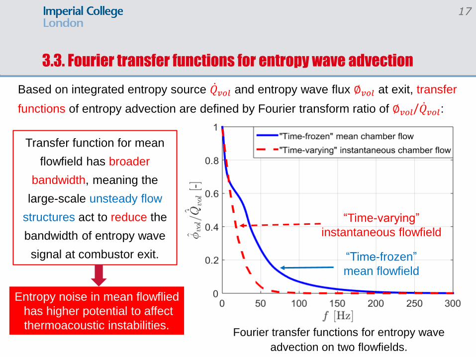
3.3. Fourier transfer functions for entropy wave advection
Based on integrated entropy source 𝑄𝑣𝑜𝑙 and entropy wave flux ∅𝑣𝑜𝑙 at exit, transfer
functions of entropy advection are defined by Fourier transform ratio of ∅𝑣𝑜𝑙/ 𝑄𝑣𝑜𝑙:
Transfer function for mean
flowfield has broader
bandwidth, meaning the
large-scale unsteady flow
structures act to reduce the
bandwidth of entropy wave
signal at combustor exit.
Fourier transfer functions for entropy wave
advection on two flowfields.
“Time-frozen”
mean flowfield
“Time-varying”
instantaneous flowfield
17
Entropy noise in mean flowflied
has higher potential to affect
thermoacoustic instabilities.

4. Conclusion & Future work
1. The entropy wave advection in a full-scale gas turbine combustor is studied:
Using turbulent reacting flow LES;
Superimposed with passive scalar entropy transport.
2. Entropy wave advection in the “time-frozen” mean flowfield:
Dispersed by a non-uniform mean velocity profile;
Entropy waves near centreline are trapped & delayed by flow recirculation zone;
Exiting amplitude follows Gaussian distribution and remains 1/3 of the source amplitude.
3. Entropy wave advection in a “time-varying” instantaneous flowfield:
Irregular & dominated by large-scale unsteady flow structures;
A shorter total exit time of 0.1s (>0.2s for mean flowfield);
Exiting amplitude follows a much flatter Gaussian response
with only 1/6 of the source amplitude.
4. Future work will focus on entropy noise effect on thermoacoustic instabilities.
18

References
19
[1] F. E. Marble, M. Candel, Acoustic disturbances from gas nonuniformities convected through
a nozzle, Journal of Sound and Vibration 55 (1977) 225–243.
[2] M. Leyko, F. Nicoud, T. Poinsot, Comparison of direct and indirect combustion noise
mechanisms in a model combustor, AIAA Journal 47 (11) (2009) 2709–2716.
[3] A. S. Morgans, C. S. Goh, J. A. Dahan, The dissipation and shear dispersion of entropy
waves in combustor thermoacoustics, Journal of Fluid Mechanics 733 (2013) R2.
[5] G. Bulat, Large eddy simulations of reacting swirling flows in an industrial burner, PhD
Thesis, Imperial College London, 2012.
[4] U. Stopper, W. Meier, R. Sadanandan, M. Stöhr, M. Aigner, G. Bulat, Exper- imental study of
industrial gas turbine flames including quantification of pres- sure influence on flow field, fuel/air
premixing and flame shape, Combustion and Flame 160 (10) (2013) 2103–2118.