Embed Size (px)
Citation preview
YOUR LIFE. OUR INSPIRATION.
Dishwasher Installation instructions
instructions d'instaHation du _ave-vaisseIRe
Instrucciones de insta_aci6n para _avavajiHas
Use and Care Manua_ _ocated on reverse side
Tourner _e guide pour _ee instructions d'utiHsation et d'entretienVo_tee e_ manua_ para encontrar _as instrucciones de uso y cuidado
9000063716 (8504)

Tabmeof Contents / Important hstructions
important Safety instructions
To avoid possible injury or property damage,OBSERVE ALL WARNINGS AND CAUTIONS.These instructions are intended for use byqualified installers onty.
The dishwasher must be installed by a qualifiedserqce technician.o in addition to these instructions, the dishwasher
shah be installed to meet aH eUectrbaUand
pUumbingcodes and ordinances (both nationaUandbcaU).
Read these installation instructions completelyand follow them carefully. They will save you timeand effort and help to ensure safety and optimum
If the dishwasher is installed in a Jocation thatexperiences freezing temperatures (e.g., in aholiday home), you must drain aH the waterfrom the dishwasher's interior. Water systemruptures that occur as a result of freezing arenot covered by warranty.
IMPORTANT* The dishwasherdrain hose must be installed
with a portion of it at least 20" (508mm) off thecabinet floor; otherwise the dishwasher may notdrain properly.
* This dishwasher is intended for residential use
only, and should not be used in commercial foodservice establishments.
o NEW INSTALLATION - If the dishwasher is anew installation, most of the work must be donebefore the dishwasher is moved into place.
* REPLACEMENT - If the dishwasher is replacinganother dishwasher, check the existingdishwasher connections for compatibility withthe new dishwasher, and replace parts asnecessary.
* This appliance has been found to be incompliance with CAN/CSA-C22.2 No. 167/UL749. It is the responsibility of the owner and theinstaller to determine if additional requirementsand standards apply in specific installations.
Inspect the DishwasherAfter unpacking the dishwasher and prior toinstallation, thoroughly inspect the dishwasher forpossible freight or cosmetic damage. Report anydamage immediately. Cosmetic defects must bereported within 5 days of installation.NOTE: Do not discard any bags or items that comewith the original package until after the entireinstallation has been completed,
Tools and Materials Needed
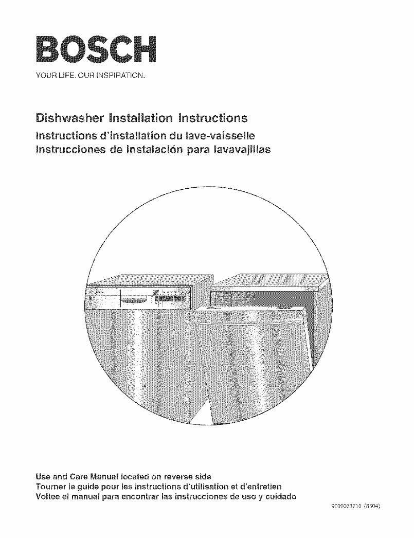
TOOLS NEEDED
Hammer
Tape Measu re
Wire Cutter
Hob Saw Adjustabb Wrench
Sbt Screwdriver
Wire Stripper
PhHHpsScrewdriver
DrHI _- Z i
%20 Screwdriver
Level
MATERIALS NEEDED(Additional materiab may be required to comply with bcal codes,)
Ebctrbal Supply CaNe - Minimum #14 AWG, 2 conductor, 1 ground, insulated copperconductors rated 75°C or higher,
_> Hot Water Supply Line - Minimum 3/8" O,D, copper tubing or metal braided dishwasher......"_*s{_: ....... supply line,
5 @}s Shut-off valve and fittings appropriate for hot water supply line (copper tubing/compression fitting, or braided hose),
90° elbow with 3/8" N,P,T, male threads on one leg, and sized to fit your water supply
<c_........... ;._",_> line (copper tubing/compression fitting, or braided hose) on the other leg,
:_;: Teflon tape or other pipe thread compound to seal plumbing connections,
UL listed conduit connector or strain relief,
2

Materials Supplied
MATERIALS SUPPUEDAccessory Parts SuppliedAccessory parts for your dishwasher come in one or more pUasticbags that are outlined bebw.NOTE: Make sure you save aHthe bags until you have compbted your installation.NOTE: Always use the suppibd or recommended hardware.
f Manual Set BagA ManuaUSet Bag is provided with each dishwasher andincludes:
A Use & Care instructions and installationinstructions (both manuab may be included
,nasingb"flip-styb'bookB Quick Reference Guide (sebct modeb)C ExtraTaH item SpdnHerD SHUand SHV installation Template (SHI and SHV _
models only); r
E White Cotton Insulation Strip (SHY66C, SHX99A,SH E66C, SH E99C, SHX57C and SHV57C models
f" Dishwasher Installation KitA Dishwasher Installation Kit is provided with eachdishwasher and includes:
F Toe Panel Screws (2 black machine screws)Note: These screws are included, but not used onmodels with the Toe Panel Installation Kit.
G Counter Top Mounting Brackets (2 '%"shaped metalbrackets)
H Mounting Bracket Screws (2 silver wood screws)1 Rubber Drain Hose Adaptor (1 Mack rubber tube)J Hose Clamps ( 1 silver spring clamp to use to
attach the rubber adaptor to the Drain Hose and 1gold screw clamp to attach the rubber adaptor to
K Wire Nuts (3 for electrical connection)L Electrical Junction Box Screws (2 silver
@--
M Leg Leveler Locking Screws (2 gold coarse
!h sad screws!f SHI/SHV Door Panel Installation Kit
A Door Panel Installation Kit is provided with selectdishwashers that use a custom wood door panel andincludes:
N Plastic Caps (2)0 Spring Tension Screws (2 larger silver machine
screws used to adjust the door springs to accom-modate doors of different weights)
P Door Mounting Brackets (2 gold metal bracketsand 2 white plastic brackets used to mount thecustom door)
Q Door Mounting Bracket Screws (8 silver woodscrews)
R Door Mounting Screws (2 long silver screws used
£_5559
@@ @,@B
f Toe Panel Installation KitA Toe Panel Installation Kit is provided on modelsSHY66C, SHX99A, SHE66C, SHE99C, SHX57C, andSHV57C. These models have a special noise reducingToe Panel with the following mounting hardware:
S Toe Panel Screws (2 black screws used to attach
T Black Plastic Base Access Panel Screws (2 longsilver screws used to attach the Black plasticBase AccessPans!!o!he d!shwasher: _J
3

EncBosure Preparation
v I
23-5/8" - 24-1/4" (600-616
23-9/I 6"
I_(598mm)
I"
(89z}mrn)mIR_mum
rY_f]q
Figure 1
Check --I
clearancebetweendishwasherdoor and wall
Countertop
Figure 2
i\
i \\
I\
ElectricaJ Shock Hazard
To avoid eJectricaJ shock, make sure the watersupply and electrical suppJy are shut off beforeinstallation or service.
ENCLOSURE PREPARATmON
NOTE: This dishwasher is designed to be enclosed on thetop and both sides by standard residentiaU kitchencabinetry.
Select a location as close to the sink as possible foreasy access to water supply and drain lines.For proper dishwasher operation and appearance, ensurethat the enclosure is square and has the dimensionsshown in Figure !.if the dishwasher is to be installed in a corner, make surethat there is adequate clearance to open the door. SeeFigure 2,
ElectricaJ Shock/Fire Hazard
To avoid eJectric shock or fire, do not allow theeJectricaJ and water supply Jines to touch.Separate channeJs are provided under thedishwasher (see page 10).
If the enclosure requires openings for the electrical supplycable, hot water supply line, and dishwasher drain hose,place them within the dimensions shown by the shadedarea of Figure 3 to avoid interference with the dishwasherframe or other components. Make the openings for theelectrical supply cable and hot water supply line 1"(25.4mm) diameter. Make the opening for the dishwasherdrain hose 1-1/4" (32mm) diameter. If the openings aremade through wood, sand them smooth. If the openingsare made through metal, make them large enough toaccommodate grommets or other protective sheaths withinside diameters of 1" (25.4mm) for the electrical supplycable and the hot water supply line, and 1-1/4" (32mm) forthe dishwasher drain hose.
Figure 3
4

30 _E
(762mm)
21 EE
(533mm)
Electrical Shock Hazard
To avoid electdcaJ shock, do not work on anenergized circuit. Doing so could resuJt in seriousinjury or death. Onty qualified electricians shouldperform electrical work. Do not attempt any workon the dishwasher etectric suppty circuit until youare certain the circuit is
de-energized.
Figure 4
Dishwasher E_ectrica_ Rating
Velts Amperes Watts
120 60 15 1,450(max)
3" A,, 1
( 75mm ° lOOmm1.
3/8"- 1/2" _ .<( 8mm- 13mm) I
Figure 5
Fire Hazard
To avoid a fire hazard, make sure electrical workis properly installed. OnJy qualified electriciansshouJd perform eJectrical work.
Electrica! SupplyThe customer has the responsibility of ensuring that thedishwasher electrical installation is in compliance with allnational and local electrical codes and ordinances. Thedishwasher is designed for an electrical supply of 120V,60 Hz, AC, connected to a dishwasher-dedicated,properly grounded electrical circuit with a fuse or breakerrated for 15 amps. Electrical supply conductors shall be aminimum #14 AWG copper wire rated at 75°C or higher.
Regardless of where the electrical supply cable enters theenclosure, position the cable 21" (533mm) from theenclosure's left side, as shown in Figure 4. Extend thecable 30" (762mm) from the enclosure's back, as shownin Figure 4.
Remove 3" =4" (75mm =lOOmm) of the cable's outercasing, as shown in Figure 5, then remove 3/8" - 1/2"(9 - 13mm) of insulation from each wire, as shown inFigure 5.
Plumbing Preparation
i355mm)Hot Water
SupplyLine
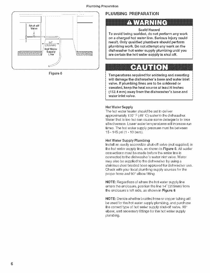
PLUMBING PREPARATmON
Scald HazardTo avoid being scaJded, do not perform any workon a charged hot water tine. Serious injury couldresult. Only qualified plumbers should performpJumbing work. Do not attempt any work on thedishwasher hot water supply pJumbing until youare certain the hot water supply is shut off.
Figure 6 Temperatures required for so(dedng and sweatingwil( damage the dishwasher's base and water inJetva(ve. If plumbing lines are to be eo)dered orsweated, keep the heat source at Jeast 6 inches(152.4 ram) away from the dishwasher's base andwater in(et vaJve.
Hot Water SupplyThe hot water heater should be set to deliverapproximately 120° F (49 ° C) water to the dishwasher,Water that is too hot can cause some detergents to loseeffectiveness, Lower water temperatures will increase runtimes, The hot water supply pressure must be between15 - 145 psi (1 - 10 bars),
Hot Water Supply PlumbingInstall an easily accessible shut-off valve (not supplied) inthe hot water supply line, as shown in Figure 6, All solderconnections must be made before the water line isconnected to the dishwasher's water inlet valve, Watermay abe be supplied to the dishwasher by using astainless steel braided hose approved for dishwasher use,Check with your local plumbing supply sources for theproper hose and 90° elbow fitting,
NOTE: Regardless of where the hot water supply lineenters the enclosure, position the line 14" (355mm) fromthe enclosure's left side, as shown in Figure 6,
NOTE: Decide whether braided hose or copper tubing wiiibe used for the hot water supply plumbing, and purchasethe correct type of hot water supply shut-off valve, 90°elbow, and necessary fittings for the hot water supply
6

Plumbing Preparation/Dishwasher Preparation
AirGap
Figure 8
PLUMBING PREPARATmON (continued)Drain PtumbingUnder Sink Drain Connectionff the dishwasher is to drain either directUyinto thehousehoUd drain pUumbingor through an air gap, install ay-branch taHpbce under the sink as shown in Figure 7,
installing an Air Gapif local ordinances require an air gap, as shown inFigure 8, install it according to the manufacturer'sinstructions,
DisposerMake sure to remove the disposer's dishwasher drainconnection plug before connecting the dishwasher drainhose, See Figure 9,
Figure 9
Step I
Step 2
Figure 10
Step I
Figure 11
DISHWASHER PREPARATmONDishwasher preparation involves four tasks:
Installing the Mounting Brackets
Installing the 90° elbow fittingJunction Box Preparation
installing the Countertop Mounting Brackets
Before installing the supplied countertop mountingbrackets, decide which method of securing thedishwasher into its enclosure wilt be used. Oncethe mounting brackets are installed on the dish-washer, removing them is difficult and will damagethe mounting brackets and the dishwasher.
The dishwasher can be secured into its enclosure in two
ways:1 Top Mount is used for countertops made of wood or
other materials that can easily drilled, Orient themounting brackets as shown in Figure 10, andposition the two small tabs on the mounting bracketsover the two slots on the dishwasher's front corners,Push the mounting brackets down firmly to insert thetabs into the slots,
2 Side Mount is used for countertops made of marne,granite, or other very hard materials that cannot beeasily drilled, Bend the mounting brackets along thesmall hobs and in the same direction as the two smalltabs, Orient the mounting brackets as shown in Figure11, and position the two small tabs on the mountingbrackets over the two slots on the dishwasher's frontcorners, Push the mounting brackets down firmly toinsert the tabs into the slots,
Tip Over HazardTo avoid a tip over hazard, do not use thedishwasher until it is completeJy installed. Whenopening the door on an uninstaHed dishwasher,carefully open the door while supporting the rearof the unit. Failure to fottow this warning canresuff in serious injury.

Dishwasher Preparation
Toe
PaneH
Figure 12
DmSHWASHER PREPARATmON (continued)
Removing the Toe Pane1FleguJar Toe PaneJThe toe paneHis HooseHyattached with tape, Remove thetape and puHHthe toe paneHaway from the dishwasher, Setthe toe paneHaside, HtwHHbe reinstaHHedHater,
PJastic Base Access Panel and Toe PaneJ (SHY660,SHX99A, SHE660, SHE990, SHX570, and SHV570modeJe only)The pHasticbase access paneHand toe paneHare in pHaceon the dishwasher, but are not attached, Remove the toepaneHfirst, as shown in Figure 12, then remove thepHasticbase access paneH,as shown in Figure 12,
Installing the 90 ° Elbow FittingNOTE: The 90° eHbowfitting is not suppHiedwith thedishwasher, and must be purchased separateHy, Hfthedishwasher's hot water suppHy Hineis to be copper tubing,make certain the eHbowhas a compression fitting,AppHyTeflon tape or other pipe seaHantwhen required,Orient the hot water suppHyconnection Hegof the eHbowtoward the channeHopening in the dishwasher base, SeeFigure 13,
Junction Box Preparation1 Remove junction box cover (see Figure 14) by HiRing
the junction box cover up and off,2 Remove the strain reHiefpilate by removing the screw
at the back of the junction box, as shown in Figure15 and sHidingthe strain reHiefpilate out,
3 Set the junction box cover, strain reHiefpilate, andscrew aside, They wiHHbe re-instaHHedHater,
Figure 13
Figure 14 Figure 15
8

Door Paneminstallation
23-1/16"
(5s6
1/4" max,
; ram) _
_ J
Figure 16
. DOOR PANEL mNSTALLATmON
SH U/SH E ModeJs - Accessory Panel lnstaJtationUfyou have an SHU/SHE modeUand have ordered anaccessory paneUkit, install the paneUprior to sliding thedishwasher into pUace.The paneUdimensions are shown inFigure 16.
SHI Modets - Panet InstallationSHUmodeUscome with additionaUmounting hardware anda tempUatesheet with installation instructions. The stain°UesssteeUmodeUs of the SHUseries aUsocome with twoextension pieces. The extension pieces are used tomatch the control panel height (Figure 17, "B" dimension)to the horizontal drawer line of the cabinets, and must beinstalled as shown in on the template sheet. The standardpiece is used for drawer heights up to 6" (152mm); thelong piece is used for drawer heights greater than 6"(152mm) but 6o7/16" (164mm) or less. Ifyou r drawers aretaller than 6o7/16", you can either slide the extensionpiece in as far as it will go, or remove it and fit the doorpanel directly below the control panel.
C
A
Figure 17
SIll/SHY Models - Panel lnstaJlationSHV models come with additional mounting hardware anda template sheet that will show you how to mount thepanel. One side of the template shows how to mount aone piece panel; the other side shows how to mount a twopiece panel. Decide which type of installation you wantbefore proceeding with the installation.
Fig. 17Dimension
SHI Only
Fig. 18 Panem DimensionDimension
20 11/16" - 25"D (SHJ) (526turn - 635mrn)
E 27 3/!6" - 30 5/16"
(SIll & SHV) (690mm - 770mm)
F 23 [€/16" - 23 3/8"(SHI & SHV) (589mrn - 594turn)
Extension "A"
Max, oMino "B .... C"
Standard Long Max,=Mino
5/16- 11/16" i11/16- 1 1/8" 55/!6" 55/8-67/16"
(8-18mm) i(18 - 29mm) (!35mm) (143 - 164mm)

PlacingtheDishwasher/SecuringtheDishwasher
_L14"
355mm) _/
J
Figure 19
Hot Water Supply Lineand Electrical SupplyCable Position inChannels
J
Figure 20
PLACmNG THE DISHWASHER
1 Straighten and position the hot water supply line andthe electrical supply cable as shown in Figure 19 sothat they wiii align with their channels under thedishwasher base,
2 Position the dishwasher close enough to the enclosureso that you can run the dishwasher drain hose to theunder sink drain connection, Make certain that the hot
water supply line and the electrical supply cable are intheir channels under the dishwasher base, as shown inFigure 20,
3 Slide the dishwsher into the opening making sure thatthe hot water supply line and the electrical supplycane stay in their proper channels,
4 Make sure the dishwasher is level, Adjust the rearleveler by turning the center screw at the front of thedishwasher, as shown in Figure 21a, Turning the screwclockwise raises the rear of the dishwasher, Adjust thefront levelers by turning them with a screwdriver, asshown in Figure 21b, Turning the levelers to the rightraises the dishwasher, if additional height is needed,shims may be added under the leveler feet,
SECURING THE DISHWASHER
1 Drive the mounting screws through the hobs in themounting brackets as shown in Figure 22 for Top orSide Mount.
f
Figure 21
10Figure 22
Leg YLevelerLockingScrew
• ScrewBoss
Figure 23
Figure 24
Drain Hose Connection
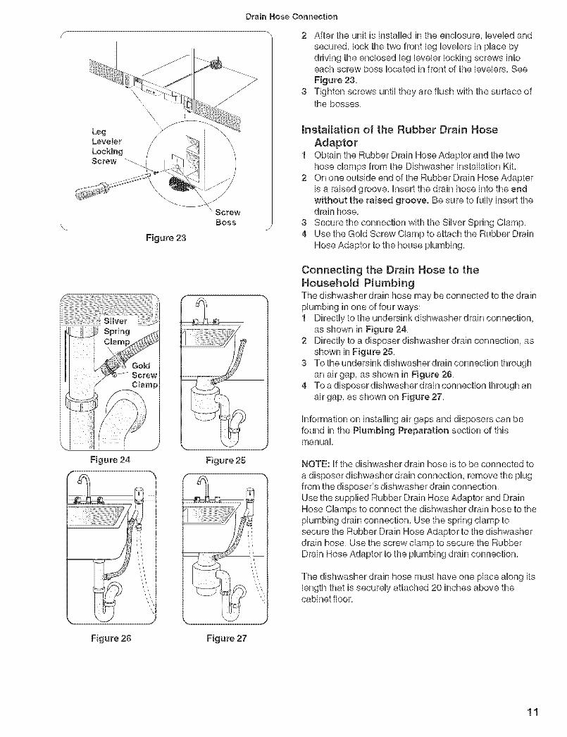
2 After the unit is instafled in the enclosure, bvebd andsecured, lock the two front bg bvebrs in place bydriving the enclosed bg bvebr locking screws intoeach screw boss located in front of the bvebrs, SeeFigure 23,
3 Tighten screws until they are flush with the surface ofthe bosses,
mnstaHation of the Rubber Drain Hose
Adaptor1 Obtain the Rubber Drain Hose Adaptor and the two
hose damps from the Dishwasher Instaflation Kit,2 On one outside end of the Rubber Drain Hose Adapter
is a raised groove, Insert the drain hose into the endwithout the raised groove. Be sure to fully insert thedrain hose,
3 Secure the connection with the Silver Spring Clamp,4 Use the Gold Screw Clamp to attach the Rubber Drain
Hose Adaptor to the house plumbing,
Figure 25
Connecting the Drain Hose to the
Household P_umbingThe dishwasher drain hose may be connected to the drainplumbing in one of four ways:1 Directly to the undersink dishwasher drain connection,
as shown in Figure 24,2 Directly to a disposer dishwasher drain connection, as
shown in Figure 25,3 To the undersink dishwasherdrain connection through
an air gap, as shown in Figure 26,4 To a disposer dishwasher drain connection through an
air gap, as shown on Figure 27,
information on installing air gaps and disposers can befound in the Ptumbing Preparation section of thismanual,
NOTE: if the dishwasher drain hose is to be connected toa disposer dishwasher drain connection, remove the plugfrom the disposer's dishwasher drain connection.Use the supplied Rubber Drain Hose Adaptor and DrainHose Clamps to connect the dishwasher drain hose to theplumbing drain connection. Use the spring clamp tosecure the Rubber Drain Hose Adaptor to the dishwasherdrain hose. Use the screw clamp to secure the RubberDrain Hose Adaptor to the plumbing drain connection.
The dishwasher drain hose must have one place along itslength that is securely attached 20 inches above thecabinet floor,
Figure 26 Figure 27
11

Hot Water Connection
HOT WATER CONNECTmON
Scald HazardTo avoid being scaJded, do not perform any workon a charged hot water tine. Serious injury couldresult. Only qualified plumbers shouJd performpJumbing work. Do not attempt any work on thedishwasher hot water supply pJumbing until youare certain the hot water supply is shut off.
NOTE: Make certain that the correct 90° eUbowfitting (notsupplied) for the hot water supply line has been pur-chased and installed on the dishwasher as described inthe Dishwasher Preparation section of this manual,The hot water supply line may be connected to thedishwasher in one of two ways:1 With braided hose,2 With copper tubing,
Braided Dishwasher Suppty HoseAfter connections are made turn on the hot water supplyto check for leaks,NOTE: Braided dishwasher supply hoses can also beused to extend pre-existing dishwasher water supplylines,
Copper Tubing
Temperatures required for soJdedng and sweatingwrit damage the dishwasher's water inlet vaJve. Ifptumbing Hnes are to be soldered or sweated,keep the heat source at Jeast 6 inches (152.4 ram)away from the dishwasher's water intet vaJve.
, if using a solder joint instead of a compression fitting,be sure to make all solder connections before
connecting the water line to the dishwasher,* Make certain there are no sharp bends or kinks in the
water line that might restrict water flow,* Be sure to use pipe thread compound or Teflon tape to
seal the connection when required,, Before connecting the copper hot water supply line to
the dishwasher, flush it with hot water to clear anyforeign material,
* Turn on the water supply to check for leaks after
NOTE: Do not use pipe sealant on compression fittings,
12

Figure 28
Figure 29
Casing
Electrical Connection
ELECTFiICAL CONNECTmON
Electrical Shock HazardTo avoid ebctricaJ shock, do not work on anenergized circuit. Doing so could result in seriousinjury or death. OnJy quaJified eJectricians shouJdperform ebctrical work. Do not attempt any workon the dishwasher electric suppJy circuit until youare certain the circuit is de-energized.
Fire Hazard
To avoid a fire hazard, make sure eJectricaJ workis properly installed. Only qualified electriciansshouJd perform electricaJ work.
Grounding instructionsThe dishwasher must be properly grounded beforeoperating, This appliance must be connected to agrounded metal permanent wiring system, or anequipment grounding conductor must be run with thecircuit conductors and connected to the equipmentgrounding terminal or lead on the dishwasher, Make surethat the dishwasher is connected to a suitable ground incompliance with all local codes or, in the absence of alocal code, with the NATIONAL ELECTRICAL CODE inthe United States or the CANADIAN ELECTRIC CODEC22,1-latest edition in Canada as well as any provincial/state or municipal or local codes that apply,
1 Retrieve the strain relief plate, and install a strain relief(not supplied) into the opening on the strain relief plate,NOTE: Orient the strain relief as shown in Figure 28,
2 Pass the electrical supply cable through the strainrelief, as shown in Figure 29, Make sure the outer wirecasing extends about 1/2" (13mm) through the strainrelief,
3 Tighten the strain relief screws,4 Slide the strain relief plate into the junction box, and
secure it to the junction box with the supplied screw,
13
EmectricalConnection/Door Tension Adjustment/Base and Toe Panel
-_ ELECTRICAL CONNECTmON (continued)
Figure 31
Figure 32J
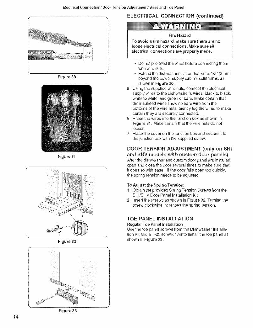
Fire Hazard
To avoid a fire hazard, make sure there are notoose eJectrical connections. Make sure aH
etectricaJ connections are properly made.
o Do not pre-twist the wires before connecting themwith wire nuts,
o Extend the dishwasher's stranded wires 1/8" (3mm)beyond the power supply cable's solid wires, asshown in Figure 30,
5 Using the supplied wire nuts, connect the electricalsupply wires to the dishwasher's wires, black to black,white to white, and green or bare, Make certain thatthe insulated wires show no bare wire from the
bottoms of the wire nuts, Gently tug the wires to makecertain they are securely connected,
6 Press the wires into the junction box as shown inFigure 31, Make certain that the wire nuts do notloosen,
7 Place the cover on the junction box and secure it tothe junction box with the supplied screw,
DOOR TENSION ADJUSTMENT (only on SHI
and SHV mode_s with custom door pane_s)After the dishwasher and custom door panel are installed,open and close the door several times to make sure thatit does so with ease, If the door falls open too quickly,the spring tension needs to be adjusted,
To Adjust the Spring Tension:1 Obtain the provided Spring Tension Screws from the
SHI/SHV Door Panel Installation Kit,
2 insert the screws as shown in Figure 32, Turning thescrew clockwise increases the spring tension,
TOE PANEL mNSTALLATmON
Regutar Toe Panel installationUse the toe panel screws from the Dishwasher Installa°tion Kit and a %20 screwdriver to install the toe panel asshown in Figure 33,
14Figure 33

Base and Toe Pane,/Final Instructions
BASE AND TOE PANEL (Continued)
PJaetic Base Access PaneJ and Toe PaneJ installation(SHY66C, SH×99A, SH E66C, SHE99C, SH×57C, andSHV57C modete only)1 PUacethe PUastb Base Access PaneUunder and up the
front bottom paneUof the dishwasher, as shown inFigure 34a,
2 insert the PUastb Base Access PaneUscrews into thePUastb Base Access PaneU,as shown in Figure 34b,Tighten the PUastb Base Access PaneUScrews,
3 PUace the Cotton UnsuUationStrip under the unit,between the bottom of the Plastic Base Access Paneland the floor, as shown in Figure 34c,
4 Attach the Toe Panel to the Plastic Base Access Panelusing the Toe Panel Screws included in the Toe PanelInstallation Kit, See Figure 34d,
NOTE: You will not use the normal Toe Panel Screwsincluded in the Dishwasher Installation Kit on thesemodels,
In some conditions, Hydrogen gas can form in ahot water system that has not been used forweeks. Hydrogen gas is e×pJoeive. Before fillinga dishwasher from a system that has been off forweeks, run the water from a nearby faucet in awett ventilated area untit there is no sound or
evidence of gas.
FINAL mNSTRUCTmONS
1 Energize the dishwasher power supply circuit,2 Consult the Dishwasher Use and Care Manual, and run
the dishwasher through one complete cycle, if thedishwasher does not operate properly, refer to the Self-Help section of the Use and Care Manual, if thedishwasher still does not operate properly, refer to theCustomer Service Section of the Use and CareManual,
15

Customer Service
CUSTOMER SERVmCEYour Bosch dishwasher requires no special care other than that described in the Care and Cleaning section of the Useand Care Manual, if you are having a problem with your dishwasher, before calling for service please refer to the Self-Help section of the Use and Care Manual, if service is necessary, contact your dealer or installer or an authorizedservice center, Do not attempt to repair the appliance yourself, Any work performed by unauthorized personnel may voidthe warranty,
if you are having a problem with your Bosch dishwasher and are not pleased with the service you have received, pleasetake the following steps (in the order listed below) until the problem is corrected to your satisfaction,
1, Contact your installer or the Bosch Authorized Service Contractor in your area,2, E-mail us from the customer service section of our website, www,boschappliances,com,3, Write us at:
BSH Home Appliances, Corp,5551 McFadden AvenueHuntington Beach, CA 92649
4, Call us at 1°800°944°2904,
Please be sure to include (if you are writing), or have available (if you are calling), the following information:oModel numberoSerial number
oDate of original purchaseDate the problem originatedExplanation of the problem
Also, if you are writing, please include a daytime phone number where you can be reached, You will find the model andserial number information on the label located on the right-hand side of the inner door of your dishwasher, see Figure 1,it will look similiar to this:
1
1Please make a copy of your invoice and keep it with this manual,
16© BSH Homo Appliances Corporation 2005 • Litho U,S,A, 07/04

Notes

Notes

Notes

© BSH Home Appliances Corporation 2005 • Litho U,S,A, 07/04
90 00 06 37 16 (8504)