Embed Size (px)
DESCRIPTION
Diseño térmico y mecánico de intercambiadores de calor
Citation preview
Diseño de Intercambiadores de Calor
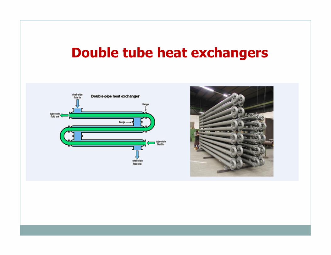
Double tube heat exchangers
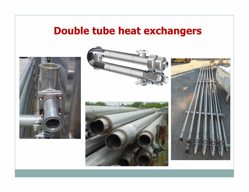
Double tube heat exchangers
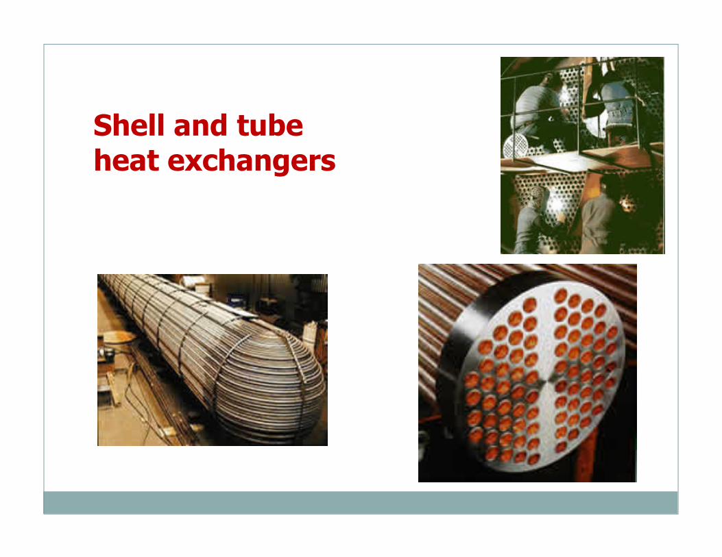
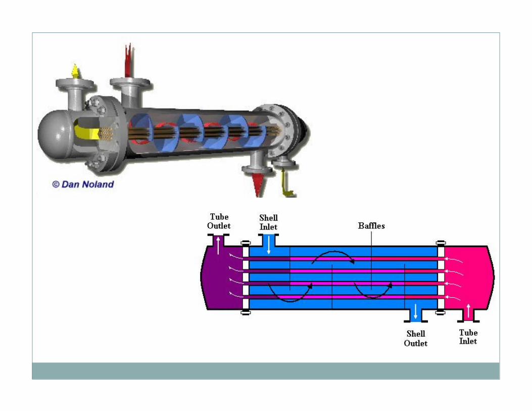
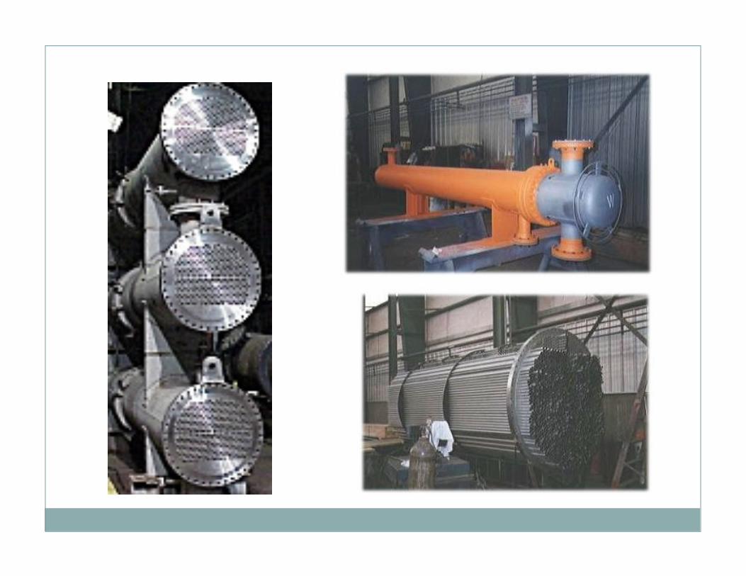
Shell and tube heat exchangers
DISEÑO TÉRMICO (OPERACIONAL)
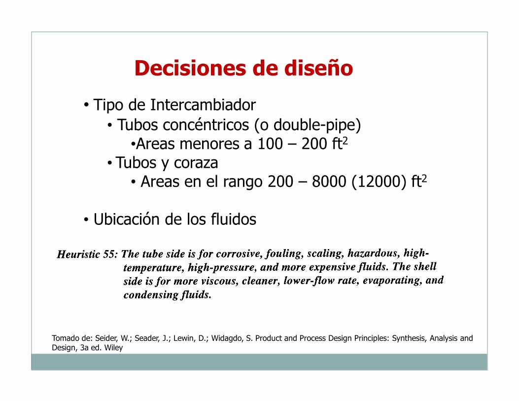
Decisiones de diseño
• Tipo de Intercambiador • Tubos concéntricos (o double-pipe)
•Areas menores a 100 – 200 ft2
• Tubos y coraza• Areas en el rango 200 – 8000 (12000) ft2
• Ubicación de los fluidos
Tomado de: Seider, W.; Seader, J.; Lewin, D.; Widagdo, S. Product and Process Design Principles: Synthesis, Analysis and Design, 3a ed. Wiley
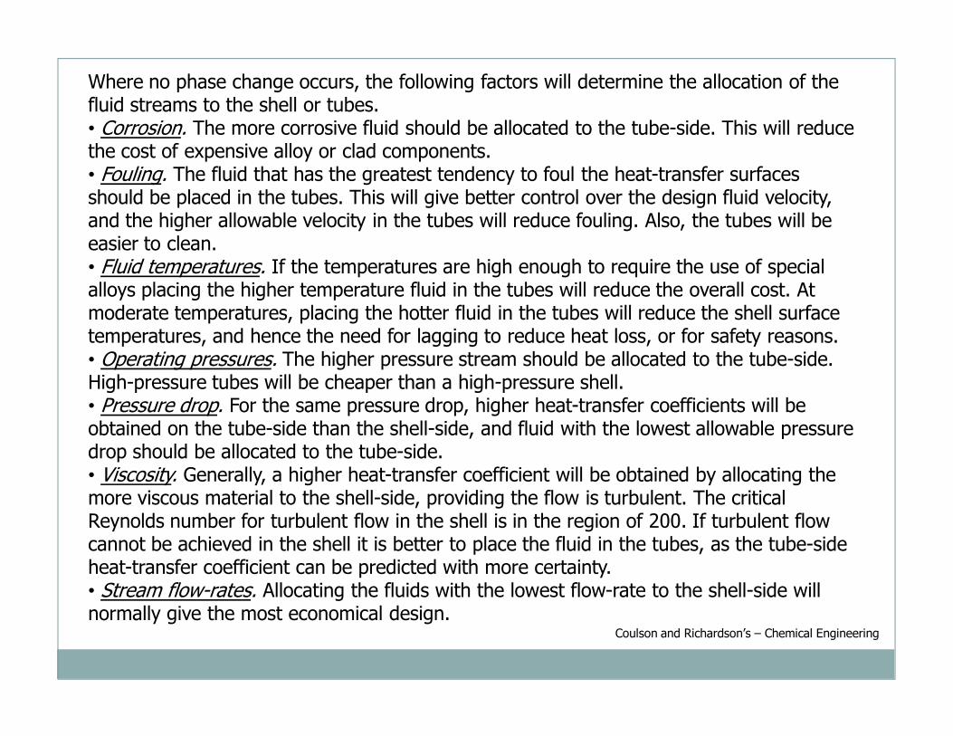
Where no phase change occurs, the following factors will determine the allocation of the fluid streams to the shell or tubes.• Corrosion. The more corrosive fluid should be allocated to the tube-side. This will reduce the cost of expensive alloy or clad components.• Fouling. The fluid that has the greatest tendency to foul the heat-transfer surfaces should be placed in the tubes. This will give better control over the design fluid velocity, and the higher allowable velocity in the tubes will reduce fouling. Also, the tubes will be easier to clean.• Fluid temperatures. If the temperatures are high enough to require the use of special alloys placing the higher temperature fluid in the tubes will reduce the overall cost. At moderate temperatures, placing the hotter fluid in the tubes will reduce the shell surface temperatures, and hence the need for lagging to reduce heat loss, or for safety reasons.• Operating pressures. The higher pressure stream should be allocated to the tube-side. High-pressure tubes will be cheaper than a high-pressure shell.• Pressure drop. For the same pressure drop, higher heat-transfer coefficients will be obtained on the tube-side than the shell-side, and fluid with the lowest allowable pressure drop should be allocated to the tube-side.• Viscosity. Generally, a higher heat-transfer coefficient will be obtained by allocating the more viscous material to the shell-side, providing the flow is turbulent. The critical Reynolds number for turbulent flow in the shell is in the region of 200. If turbulent flow cannot be achieved in the shell it is better to place the fluid in the tubes, as the tube-side heat-transfer coefficient can be predicted with more certainty.• Stream flow-rates. Allocating the fluids with the lowest flow-rate to the shell-side will normally give the most economical design.
Coulson and Richardson’s – Chemical Engineering
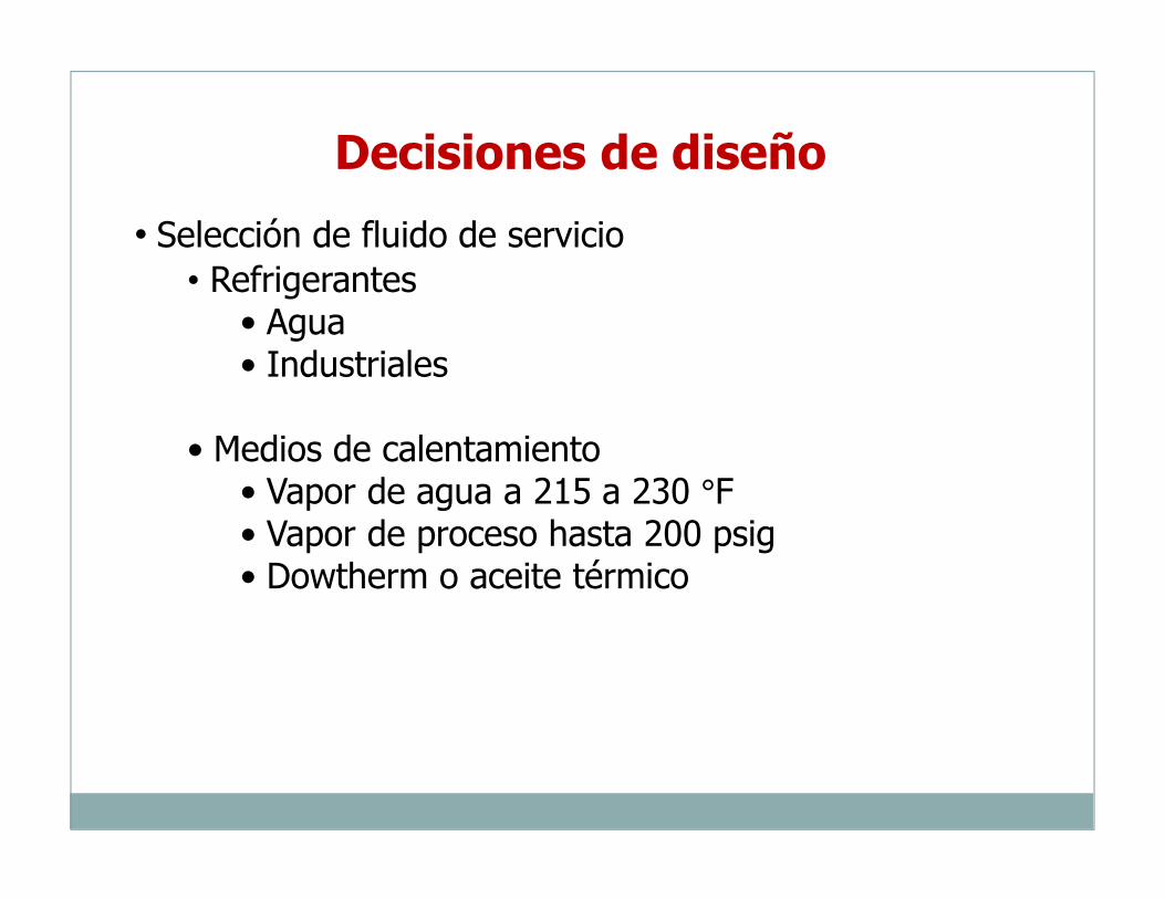
• Selección de fluido de servicio• Refrigerantes
• Agua• Industriales
• Medios de calentamiento• Vapor de agua a 215 a 230 °F• Vapor de proceso hasta 200 psig• Dowtherm o aceite térmico
Decisiones de diseño
Decisiones de diseño
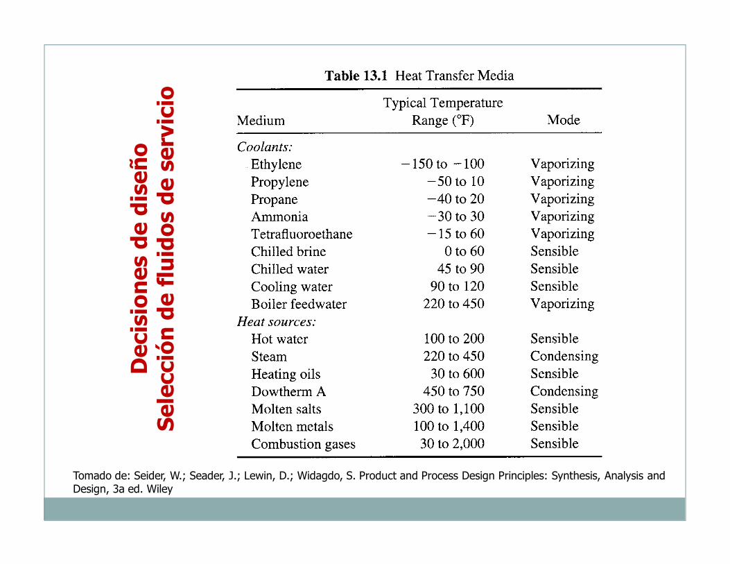
Selección de fluidos de servicio
Tomado de: Seider, W.; Seader, J.; Lewin, D.; Widagdo, S. Product and Process Design Principles: Synthesis, Analysis and Design, 3a ed. Wiley
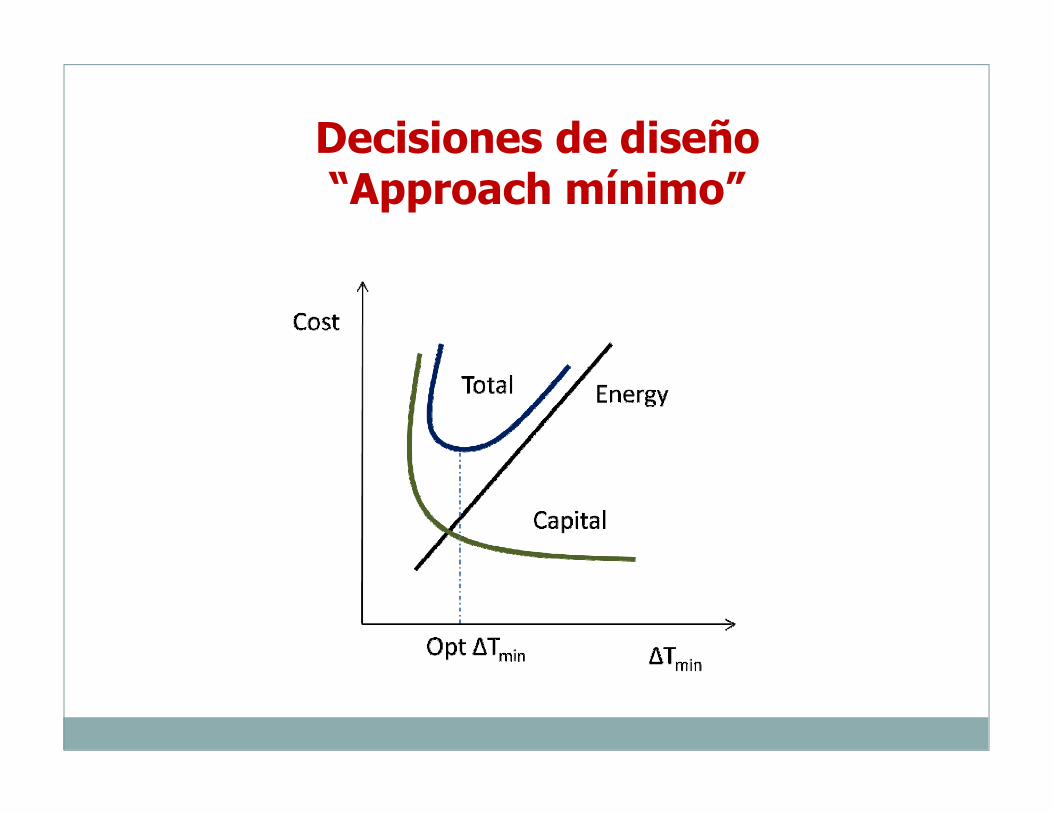
Decisiones de diseño“Approach mínimo”

Decisiones de diseño“Approach mínimo”
Tomado de: Seider, W.; Seader, J.; Lewin, D.; Widagdo, S. Product and Process Design Principles: Synthesis, Analysis and Design, 3a ed. Wiley
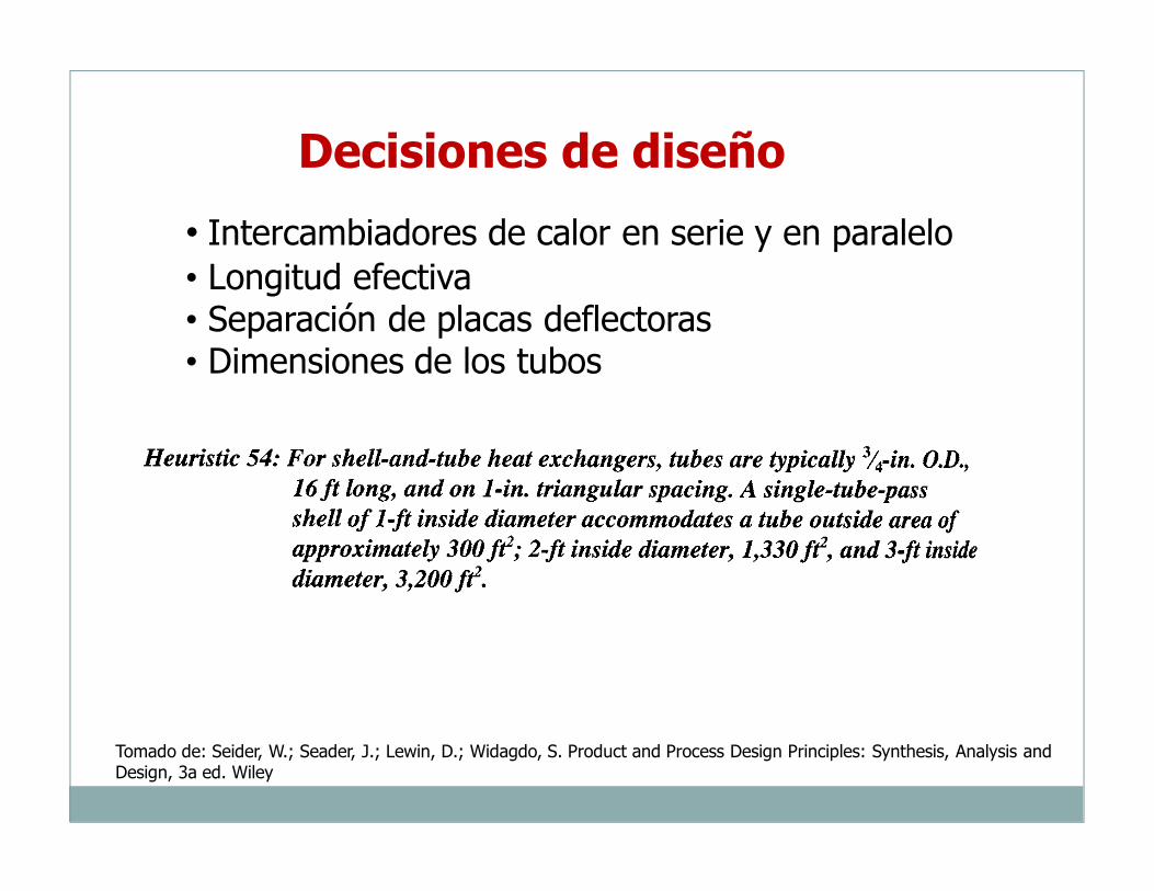
Decisiones de diseño
• Intercambiadores de calor en serie y en paralelo• Longitud efectiva• Separación de placas deflectoras• Dimensiones de los tubos
Tomado de: Seider, W.; Seader, J.; Lewin, D.; Widagdo, S. Product and Process Design Principles: Synthesis, Analysis and Design, 3a ed. Wiley
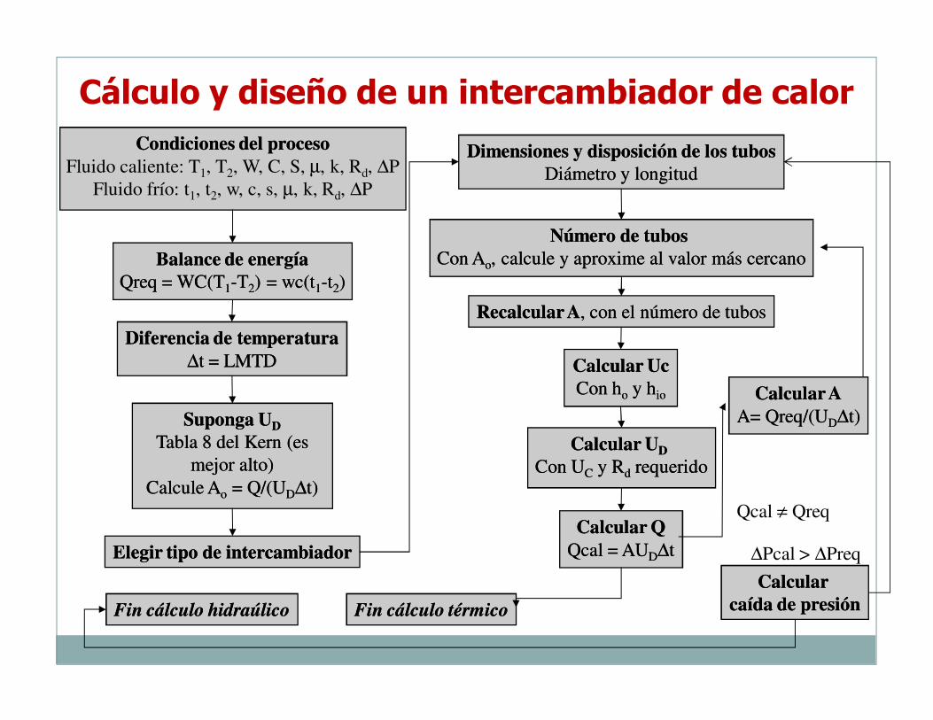
Cálculo y diseño de un intercambiador de calorCondiciones del procesoCondiciones del proceso
Fluido caliente: T1, T2, W, C, S, µ, k, Rd, ∆P
Fluido frío: t1, t2, w, c, s, µ, k, Rd, ∆P
Balance de energíaBalance de energía
Qreq = WC(TQreq = WC(T11--TT22) = wc(t) = wc(t11--tt22))
Diferencia de temperaturaDiferencia de temperatura
∆∆t = LMTDt = LMTD
Suponga USuponga UDD
Tabla 8 del Kern (es Tabla 8 del Kern (es
mejor alto)mejor alto)
Calcule ACalcule Aoo = Q/(U= Q/(UDD∆∆t)t)
Recalcular ARecalcular A, con el número de tubos, con el número de tubos
Elegir tipo de intercambiadorElegir tipo de intercambiador
Número de tubosNúmero de tubos
Con ACon Aoo, calcule y aproxime al valor más cercano, calcule y aproxime al valor más cercano
Dimensiones y disposición de los tubosDimensiones y disposición de los tubos
Diámetro y longitudDiámetro y longitud
Calcular UcCalcular Uc
Con hCon hoo y hy hioio
Calcular QCalcular Q
Qcal = AUQcal = AUDD∆∆tt
Qcal ≠ Qreq
Fin cálculo térmicoFin cálculo térmico
Calcular UCalcular UDD
Con UCon UCC y Ry Rdd requeridorequerido
Calcular ACalcular A
A= Qreq/(UA= Qreq/(UDD∆∆t)t)
Calcular Calcular
caída de presióncaída de presión
∆Pcal > ∆Preq
Fin cálculo hidraúlicoFin cálculo hidraúlico
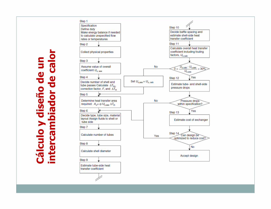
Cálculo y diseño de un
intercam
biador de calor
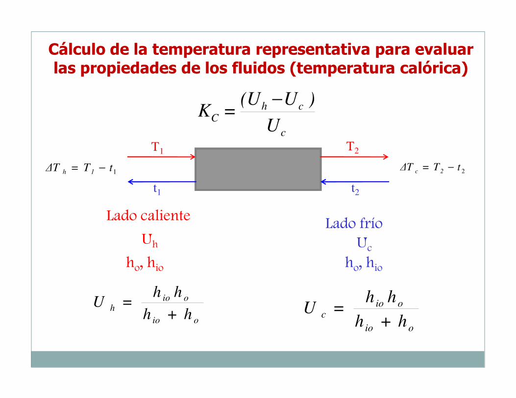
c
chC
U
)U(U=K
−
1tT=∆T 1h − 2tT=∆T2c
−
T1 T2
t1 t2
Lado calienteLado frío
Uh Ucho, hio ho, hio
oio
oioh
h+h
hh=U
oio
oioc
h+h
hh=U
Cálculo de la temperatura representativa para evaluar las propiedades de los fluidos (temperatura calórica)
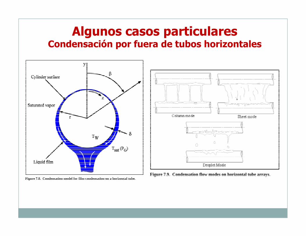
Algunos casos particularesCondensación por fuera de tubos horizontales
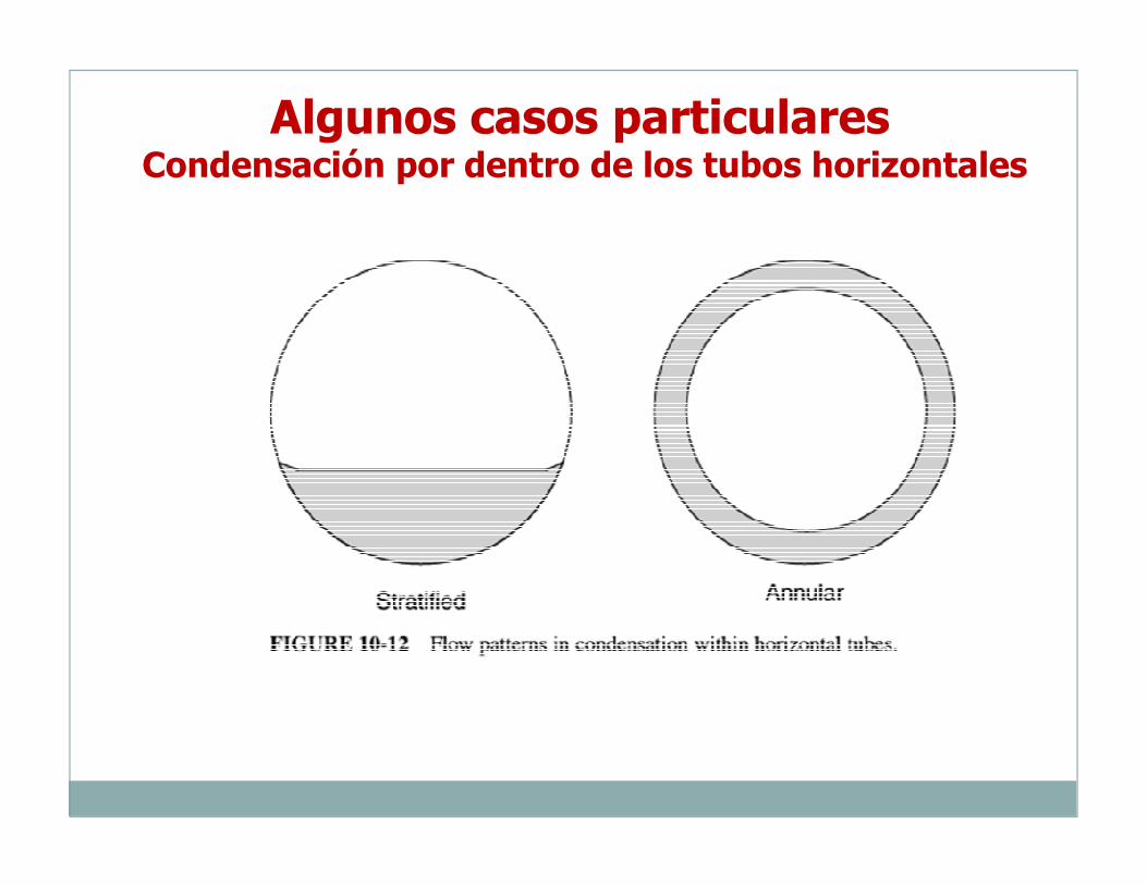
Algunos casos particularesCondensación por dentro de los tubos horizontales
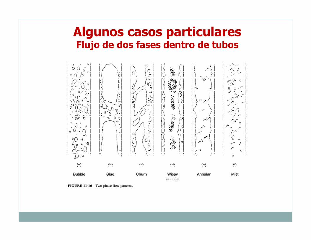
Algunos casos particularesFlujo de dos fases dentro de tubos
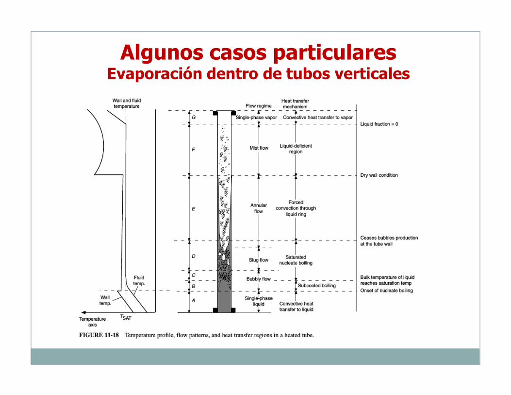
Algunos casos particularesEvaporación dentro de tubos verticales
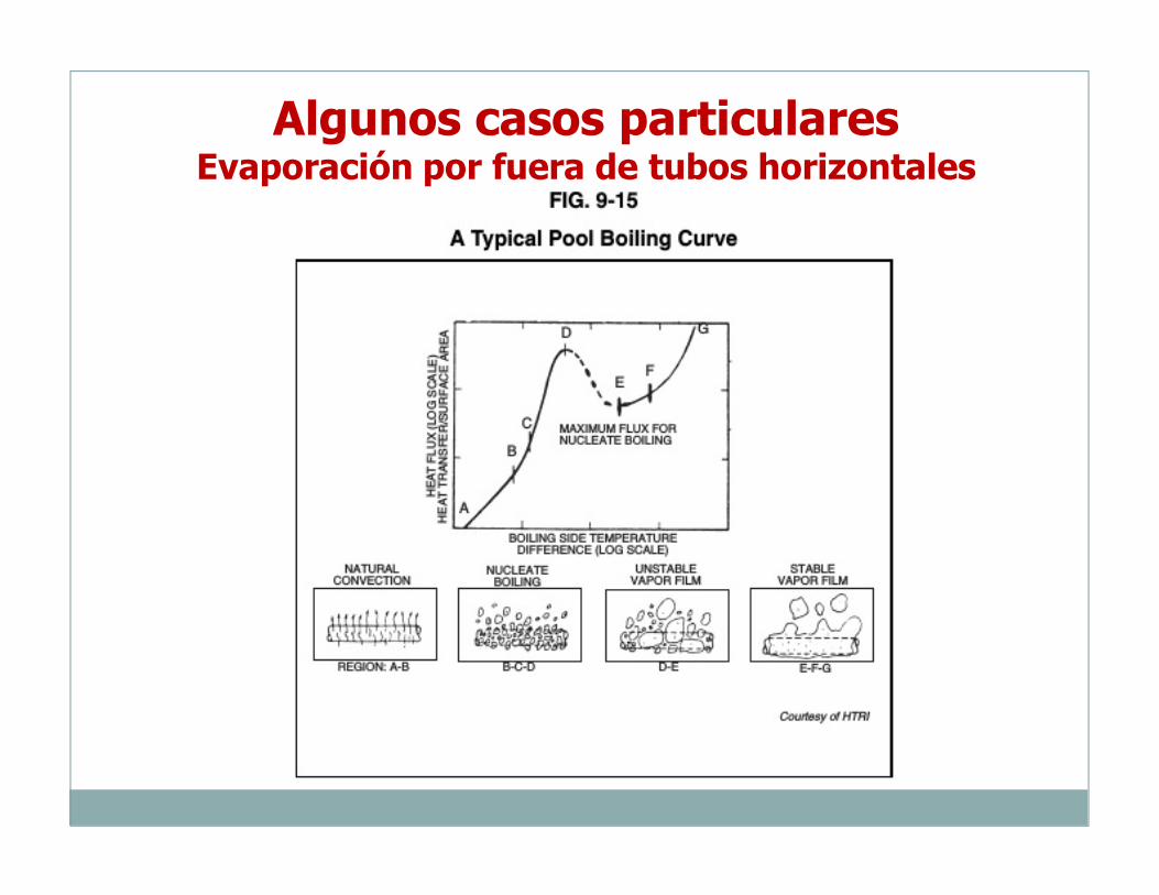
Algunos casos particularesEvaporación por fuera de tubos horizontales
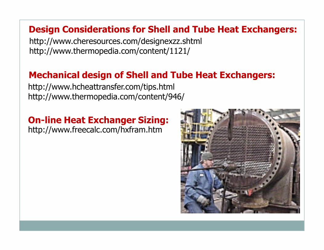
http://www.cheresources.com/designexzz.shtmlhttp://www.thermopedia.com/content/1121/
Design Considerations for Shell and Tube Heat Exchangers:
On-line Heat Exchanger Sizing:http://www.freecalc.com/hxfram.htm
Mechanical design of Shell and Tube Heat Exchangers:http://www.hcheattransfer.com/tips.htmlhttp://www.thermopedia.com/content/946/

DISEÑO MECÁNICO
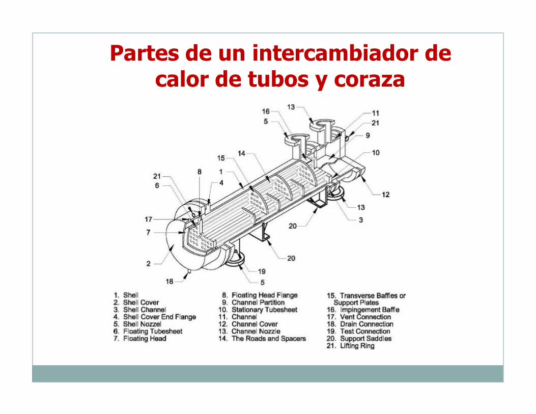
Partes de un intercambiador de calor de tubos y coraza
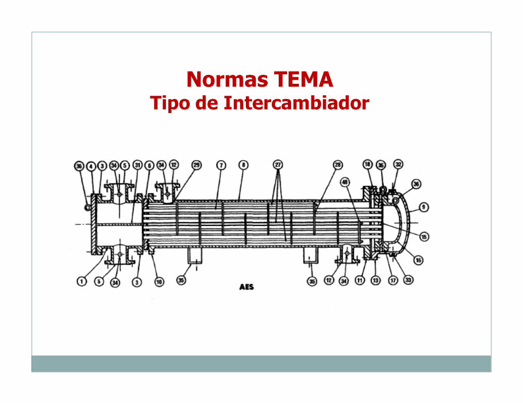
Normas TEMATipo de Intercambiador
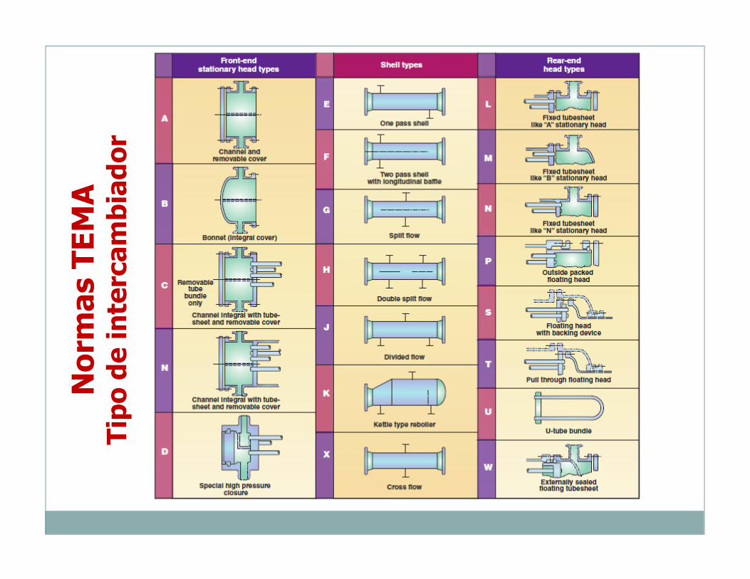
Norm
as TEMA
Tipo de intercam
biador
Norm
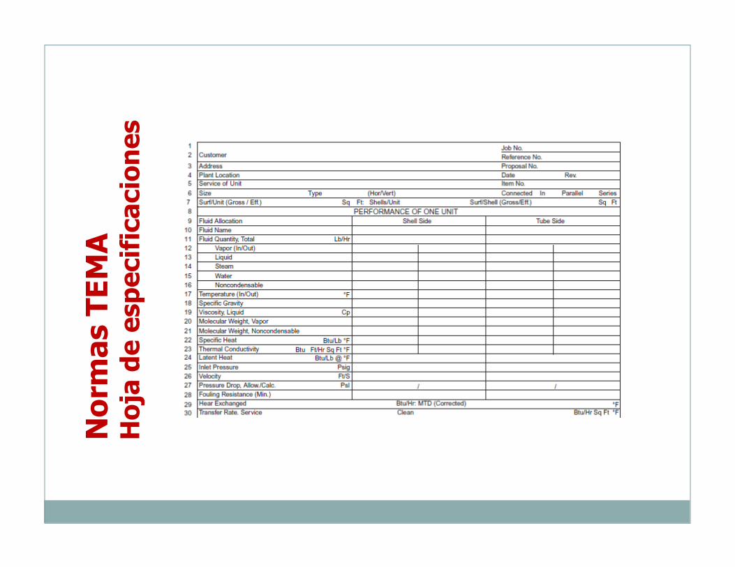
as TEMA
Hoja de especificaciones
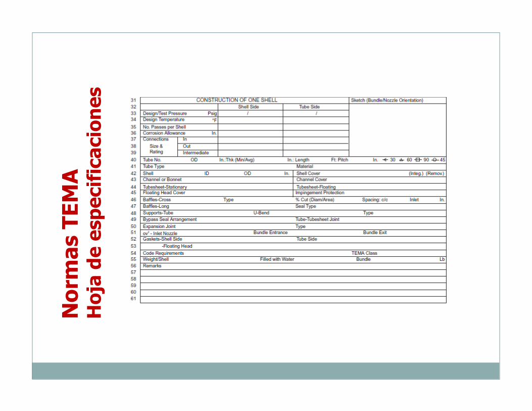
Norm
as TEMA
Hoja de especificaciones
Algunas referencias
• Tapias et al. “Métodos y algoritmos de diseño en ingeniería química.”• Kern. “Process heat transfer.”• Ludwig, E. “Applied Process Design for Chemical Petrochemical Plants.” 4th ed.• Brannan. “Rules of Thumb for Chemical Engineers.” 4th
ed.• Normas TEMA.• Cao. “Heat Transfer in Process Engineering.”• Faccini. “Ejecución de proyectos de ingeniería.”