Embed Size (px)
Citation preview

IOP Conference Series Materials Science and Engineering
OPEN ACCESS
Discontinuous Galerkin method based onperidynamic theoryTo cite this article H G Aksoy and E enocak 2010 IOP Conf Ser Mater Sci Eng 10 012227
View the article online for updates and enhancements
You may also likeMultiscale simulation of the heat and masstransfer with Brinkman modelValentin Alekseev Maria Vasilyeva andVasily Vasiliev
-
A multi-scale discontinuous Galerkinmethod for mathematical modeling of heatconduction processes with phasetransitions in heterogeneous mediaS I Markov E P Shurina and N B Itkina
-
HDG schemes for stationary convection-diffusion problemsR Z Dautov and E M Fedotov
-
This content was downloaded from IP address 18119944104 on 06112021 at 1952
Discontinuous Galerkin method based on
peridynamic theory
H G Aksoy and E Senocak12
1 Istanbul Technical University Department of Mechanical Engineering Inonu Cad No87Gumussuyu 34437 Istanbul Turkey
E-mail senocakituedutr
Abstract In this study a novel formulation of the discontinuous Galerkin method is derivedbased on peridynamic theory Derivation of the proposed formulation is presented Numericalanalysis are performed for 2D problems and results are compared to their respective knownexact solutions Numerical tests are performed at the incompressible limit The proposeddiscontinuous Galerkin formulation is found to be robust and successful in modelling elastostaticproblems
1 IntroductionModeling of discontinuities in solid mechanics such as shock waves and crack surfaces is one ofthe major research area in modeling the mechanical behavior of materials In these problemsthe degradation of numerical accuracy around the discontinuity affects the conservation ofenergy momentum and angular momentum In solid dynamics problems such as impact plasticdeformation and crack propagation problems the conservation of energy and momentum in thenumerical method are important
In recent years researchers have focused on conservative numerical methods Among thesenumerical methods the discontinuous Galerkin method (DGM) has been of interest to manyresearchers DGM is first proposed for the time integration of first order hyperbolic equationsfor the solution of the neutron transport problem in Ref [1] The time discontinuous Galerkin(TDG) method has also been used for the time integration of fluid flow and heat conductionproblems [2 3]
DGM allows for discontinuities at the element interfaces and it is therefore advantageousto use DGM for shock wave propagation problems in fluid mechanics Approximate Riemannfluxes are used for the calculation of interelement fluxes [3 4] More recently DGM has beendeveloped for the discretization of second order PDEs for the discretization of diffusive terms inNavier-Stokersquos equations [5 6]
Theoretical and numerical studies on modeling solid dynamics problems with discontinuitieswithin the variational framework goes back to 70rsquos [7 8] It is advantageous to use DGMfor shock wave and crack propagation problems as it allows for discontinuities at the elementinterfaces Another advantage of the DGM is that sudden changes in material properties areallowed at the element interfaces for layered materials Different formulations are proposed by
2 On leave University of Pitesti Faculty of Mechanics and Technology Pitesti Arges Romania
WCCMAPCOM 2010 IOP PublishingIOP Conf Series Materials Science and Engineering 10 (2010) 012227 doi1010881757-899X101012227
ccopy 2010 Published under licence by IOP Publishing Ltd 1
different researchers according to the problem of interest A mixed formulation is proposed formodeling discontinuities in Ref [7] A novel formulation is derived in Ref [8] and is used forthe modeling of shock wave propagation problems by a shock fitting [9] In solid mechanicsDGM has been begun to be used for time integration in elastodynamic problems [10] Recentstudies about DGM are on formulations with discontinuous displacement fields Consistencyof the displacement field at element interfaces plays a key role in the stability in theseformulations [11 12] A locking free DGM for the modelingof linear elastic materials is proposedin Ref [13] In this study the method of Nitsche [14] is reformulated and stabilization termswhich are for the consistency of displacements at element interfaces are added A nonsymmetricformulation proposed in Ref [5] for elliptic equations is derived for solid dynamics along withTDG for a space-time discontinuous as presented in Refs [15 16] The Bubnov-Galerkin methodis used in Ref [17] and in this study Godunov values calculated from neighboring elementsare used as target values at element interfaces The DGM proposed in Ref [18] for ellipticproblems is derived for linear elastostatics in Ref [19] which is generalized for nonlinear elasticproblems in Ref [20] The Hu-Washizu-de Veubeke functional is used for the derivation of DGMfor hyperelastic materials in [21] which is extended to non-linear solid dynamics problems in[22] A mixed formulation is proposed for linear elasticity in Ref [23] namely the hybridizablediscontinuous Galerkin method
Although the proposed formulations are consistent by means of displacement field numericalerror in the displacement field at element interfaces [20] is the drawback of these formulationsIn this study a novel formulation of the discontinuous Galerkin method based on peridynamictheory [24] is proposed for elastostatic problems A Single element connected to a rigid walland an in-plane loaded square problem are solved in order to determine the numerical propertiesof the proposed method
2 Equations of ElastostaticsIn this study we consider a linear elastic body occupying a space Ω sub Rd where d is the numberof dimensions The boundary of Ω is denoted by Γ ΓD and ΓN denote the subregions of Γwhere displacement and traction force are specified such that
Γ = ΓN
cupΓD and ΓN
capΓD = empty (1)
The equilibrium equation for elastostatics can be written as follows
nabla middot σ + b = 0 in Ω (2)
In the equation above σ is the Cauchy stress tensor and b represents the body forces per unitmassBoundary conditions can be defined as follows
σ middot n = t in ΓN u = u in ΓD
(3)
where t and u are the specified traction force and displacement respectivelyFor a linear elastic material the stress tensor can be defined as
σ = C nablau (4)
where C is the stiffness tensor
WCCMAPCOM 2010 IOP PublishingIOP Conf Series Materials Science and Engineering 10 (2010) 012227 doi1010881757-899X101012227
2
Figure 1 Typical solution domain
3 Weak Formulation for Discontinuous Galerkin MethodPh(Ω) is a regular partition of the domain Ω such that Ph(Ω) is generated by division of Ω intoNe number of Ωe subdomains such that Ωe
capΩnb = empty for e = nb Boundary of each subdomain
Ωe is partially continuous arc for two dimensional problems and partially continuous surfacefor three dimensional problems Γint defines the interelement boundary of any two adjacentelements and ΓI is the sum of interior boundaries such that
Γint = Γe
capΓnb foralle = nb (5)
ΓI =cup
Γint (6)
We define the broken space of trial functions Vn in which u(x) is smooth and continuous vectorfunction for every Ωe Similarly defined is the broken space of weighting functions Wn in whichw(x) is smooth and continuous vector function for every Ωe Elements of Vn and Wn arenon-zero vector functions in Ωe and zero elsewhere A typical solution domain in space is shownin Figure (1)Let x isin Γint xe = x minus ϵn and xnb = x + ϵn Note that ne = minusnnb = n where ne is the unitoutward vector of subdomain ΩeDifference and averaging operators can be defined for an arbitrary variable ϕ as follows
[ϕ(x))] = (ϕ(xnb)minus ϕ(xe))
lt ϕ(x) gt= (ϕ(xnb) + ϕ(xe))2
We begin with the weighting the equilibrium equation in an elementwise manner The weightedform of the Equation (2) can be written assum
ΩeisinPh
intΩe
w middot (nabla middot σ + b)dv = 0 (7)
where w is an arbitrary vector of weighting functions Taking the first term in Equation (7) fora single element and integrating by parts we obtain equationint
Ωe
w middot (nabla middot σ)dv =sumΩe
(
intΓe
w middot tlowastndsminusintΩe
nablaw σdv) (8)
WCCMAPCOM 2010 IOP PublishingIOP Conf Series Materials Science and Engineering 10 (2010) 012227 doi1010881757-899X101012227
3
In Equation (8) tlowastn is the approximate traction force at the interface of two adjacent elements
31 Approximate Traction ForceDifferent from the previous formulations presented in the literature an approximate tractionforce based on the peridynamic theory [24] is proposed In peridynamic theory pairwise forcefunctions based on displacements similar to that in the atomistic models are used In this studypairwise force functions are used to calculate the approximate traction forces at interelementboundaries Therefore there is no need for additional terms to have consistent formulation inthe displacement fieldThe pairwise force function at point xi due to the xj is defined as
fij = fij(xj minus xiu(xj)minus u(xi)) (9)
such that
fij = minusfji (10)
The relation between the displacements and pairwise force is given in [25] for multidimensionalproblems as
f = C(ξ)(u(xj)minus u(xi)) (11)
In Equation (11) C(ξ) is the tensorial micromodulus and ξ = xj minus xiFor pairwise force function to satisfy Equation (10) the micromodulus function must be aneven function Additionally as the distance between interacting points increases the magnitudeof the pairwise force function must decrease Consequently the micromodulus function mustsatisfy the following conditions
C(ξ) rarr 0 as |ξ| rarr infinC(ξ) gt 0
(12)
We assume that only particles along the interelement boundaries between two neighboringelements interact with each other Thus we can use a micromodulus function for one dimensionalproblems In this study we use the micromodulus function proposed in Ref[26] given as
C(ξ) = 4E
δ3radicπeminus(|ξ|δ)2 (13)
In Equation (13) δ is the horizon which controls the nonlocal character of the micromodulus andE is the Youngrsquos modulus In this study the horizon is controlled by a non-locality parameternd such that δ = hfnd where hf is edge length of an elementThe approximate traction force tlowastn at point x isin Γe can be calculated as follows
tlowastn(x) =
intΓnb
f(xprime minus xu(xprime)minus u(x))dsprime (14)
where xprime isin Γnb
32 Discontinuous Galerkin MethodThe resulting bilinear and linear operators are derived as follows
B(uw) =sum
ΩeisinPh
intΩe
nablaw σdv +
Nisumi=1
intSi
[w] middot (C(ξ)[u])dS +
intSD
w middot (C(ξ) u)dS (15)
WCCMAPCOM 2010 IOP PublishingIOP Conf Series Materials Science and Engineering 10 (2010) 012227 doi1010881757-899X101012227
4
L(w) =sum
ΩeisinPh
intΩe
w middot bdv +intSD
w middot (C(ξ) u)dS +sum
ΓeisinΓN
intΓe
w middot tds (16)
In Equations (15) and (16) Si = Γe times Γnb SD = Γe times ΓD and Ni is the number of interelementboundaries The solution of B(uw) = L(w) is the solution of the problem defined byEquation (2) and Equation (3)
4 Numerical Implementation
Figure 2 Quadrature points for approximate traction force
Let uh(x) be the approximate solution of u(x) The bilinear operator after evaluating theintegrals can be written as follows
B(uh(x)w) =
Nesume=1
(Keuhe + Fe(u
he ) + Fnb(u
hnb) (17)
in which Ke is the element stiffness matrix The terms Fe and Fnb arise from the surfaceintegrals along the element interfaces In order to computate Fe and Fnb approximate tractionforce at quadrature point i is calculated as a first step For this purpose the integration on alenth of 2δ on the edge of neighbor element is performed (see Figure (2))In the following equations superscript h is dropped for simplicity
Nesume=1
(Keue +sumnb
Knbunb minus Fext) = 0 (18)
where Ke is the modified element stiffness matrix and defined as Ke = Ke + partFepartue
andsumnbKnbunb =
partFnbpartunb
Equation (18) is solved by using Bi-CGSTAB algorithm [27] along with the ILU(0)preconditioner
WCCMAPCOM 2010 IOP PublishingIOP Conf Series Materials Science and Engineering 10 (2010) 012227 doi1010881757-899X101012227
5
5 Numerical ExamplesIn this section two different problems are solved in order to determine the numerical propertiesof the peridynamic discontinuous Galerkin method (PDGM) Results are compared to that ofnumerical results obtained from the symmetric discontinuous Galerkin method (SDGM) [13]and the nonsymmetric discontinuous Gakerkin method (NSDGM) [16]
51 Single Element Connected To a Rigid WallIn this example a single element connected to a rigid wall under tension and shear loads isstudied The geometryof the problems are shown in Figure (3) Solution is obtained as aparameter of the element edge length h in order to determine the effect of the PDGM oncharacteristic element behavior Bilinear basis functions are used Youngrsquos modulus E is 1 Nm2
and Poissonrsquos ratio ν is 03
(a) Tension loaded element (b) Shear loaded element
Figure 3 Loading conditions of single element connected to a rigid wall
L1 norm of the error at node 1 is shown in Figure (4) It is seen that error is consistentlydecreasing in all methods The order of error in PDGM is lower than NSDGM and SDGM inboth tension and shear loading When element size is unity the order of error in the case ofshear loading is 01 for both NSDGM and SDGM where as PDGM shows an improved resultof 001 The order of error decreases to 001 in NSDGM and SDM and 10minus3 in PDGM undertension
52 In-Plane Loaded SquareIn-plane loaded square with dirichlet boundary conditions is solved using plane strain conditionswhich is shown in Figure (5) Body forces per unit volume are given by Equation (20) and areapplied to obtain the displacement field given in Equation (19) Triangular and quadrilateralelements are used with linear and bilinear basis functions respectively Each side of the domainis divided into 2 4 8 16 and 32 elements Meshes with 16times16 elements are shown in Figure (6)Young modulus is taken as E = 1 Nm2
ux(x y) = x(1minus x)y(1minus y)uy(x y) = x(1minus x)y(1minus y)
(19)
bx(x y) =8E((4νminus2)x2+2(3+2ν(yminus1)minus2y)yminus4x(minus1+ν+y)minus1)
1minusνminus2ν2
by(x y) =8E(4(νminus1)x2+x(6minus4νminus4y)+2(2+2ν(yminus1)minusy)yminus1)
1minusνminus2ν2
(20)
L2 norm of the error at different element sizes are plotted in Figure (7) for triangular andquadrilateral elements when Poissonrsquos ratio is ν = 025 It is seen that the change in non-locality
WCCMAPCOM 2010 IOP PublishingIOP Conf Series Materials Science and Engineering 10 (2010) 012227 doi1010881757-899X101012227
6
h
|e1|
10-4 10-3 10-2 10-1 10010-11
10-9
10-7
10-5
10-3
10-1
101
NSDGMSDMNSDGM γ=3SDGM γ=3NSDGM γ=10SDGM γ=10PDGM
(a) Element under tension
h
|e1|
10-4 10-3 10-2 10-1 10010-11
10-9
10-7
10-5
10-3
10-1
101
NSDGMSDMNSDGM γ=3SDGM γ=3NSDGM γ=10SDGM γ=10PDGM
(b) Element under shear
Figure 4 L1 norm of the error at point 1
Figure 5 In plane loaded square domain
parameter nd does not change the result significantly for both types of grids The error in PDGMis higher than NSDGM and SDGM for courser grids when triangular elements are used As thegrid is refined the error in PDGM becomes lower than NSDGM and SDGM In the case of thequadrilateral grid the error in NSDGM is lower than that for PDGM and SDGM In additionas the grid is refined it is seen that convergence rate decreases below 2 for both in PDGM andSDGM
The sum of jumps in displacement at the element interfaces are shown as a measure ofnumerical consistency at the element interfaces in Figure (8) The sum of jumps in displacementis almost identical and independent of the penalty parameter γ in SDGM and NSDGM whenthe grids with triangular elements are used The sum of jumps in displacement decreases withthe increase in non-locality parameter nd in PDGM In addition it is three orders of magnitudelower in PDGM than in NSDGM and SDGM Though there are differences in sum of jumps indisplacement in SDGM and NSDGM results obtained for PDGM are still lower than the twopreceding methods
WCCMAPCOM 2010 IOP PublishingIOP Conf Series Materials Science and Engineering 10 (2010) 012227 doi1010881757-899X101012227
7
(a) Triangular Elements (b) Quadrilateral Elements
Figure 6 16times 16 grid
h
||e|| 2
10-2 10-1 10010-4
10-3
10-2
10-1
100
PDGM nd=3PDGM nd=6PDGM nd=12PDGM nd=24NSDGM γ=3NSDGM γ=10SDGM γ=3SDGM γ=10
1
2
(a) Triangular Elements
h
||e|| 2
10-2 10-1 10010-4
10-3
10-2
10-1
100
PDGM nd=3PDGM nd=6PDGM nd=12PDGM nd=24NSDGM γ=3NSDGM γ=10SDGM γ=3SDGM γ=10
1
2
(b) Quadrilateral Elements
Figure 7 L2 norm of the error at different element sizes
L2 norm of the error at the incompressible limit is given in Table (1) and Table (2) for32times 32 gridsValues higher than 1 are shown with dashed lines and the solution is assumed tohave diverged It is observed that grid type has an effect on the stability and quadrilateral gridsare more stable at the incompressible limit Error in computations with PDGM is higher onquadrilateral grids than triangular grids Additionally error in the incompressible limit is lowerin PDGM than in SDGM and NSDGM on triangular grids and PDGM is more stable in bothgrid types
WCCMAPCOM 2010 IOP PublishingIOP Conf Series Materials Science and Engineering 10 (2010) 012227 doi1010881757-899X101012227
8
h
Σ|[u
]|
10-2 10-1 10010-7
10-6
10-5
10-4
10-3
10-2
10-1
PDGM nd=3PDGM nd=6PDGM nd=12PDGM nd=24NSDGM γ=3NSDGM γ=10SDGM γ=3SDGM γ=10
(a) Triangular Elements
h
Σ|[u
]|
10-2 10-1 10010-7
10-6
10-5
10-4
10-3
10-2
10-1
PDGM nd=3PDGM nd=6PDGM nd=12PDGM nd=24NSDGM γ=3NSDGM γ=10SDGM γ=3SDGM γ=10
(b) Quadrilateral Elements
Figure 8 Sum of error due to jump in displacement at the interelement boundaries
Table 1 L2 norm of the error for different Poissonrsquos ratios on 32 times 32 grid with triangularelements
ν025 049 0499 04999
PDGM nd = 3 0001485 0060392 0617792 minusminusnd = 6 0000945 0016615 0155059 minusminusnd = 12 0000964 0006299 0041466 0020254nd = 24 0000981 0004355 0019944 0005263
NSDGM γ = 3 00016037 00098552 minusminus 08978276γ = 10 00010152 00064710 00539982 6139811822
SDGM γ = 3 0000823 0754250 minusminus minusminusγ = 10 0000883 0754247 0754250 minusminus
Table 2 L2 norm of the error for different Poissonrsquos ratios 32 times 32 grid with quadrilateralelements
ν025 049 0499 04999
PDGM nd = 3 0006021 0037528 0278704 minusminusnd = 6 0005345 0020191 0103343 0685498nd = 12 0005178 0016649 0081792 0250924nd = 24 0005137 0015877 0080576 0201159
NSDGM γ = 3 0000869 0001352 0001352 0013105γ = 10 0000670 0001080 0002763 0007465
SDGM γ = 3 0012168 0766051 minusminus minusminusγ = 10 0001350 0001409 0002115 minusminus
WCCMAPCOM 2010 IOP PublishingIOP Conf Series Materials Science and Engineering 10 (2010) 012227 doi1010881757-899X101012227
9
6 ConclusionIn this study a novel DGM formulation is derived based on peridynamic theory Error iscalculated for a single element connected to a rigid wall and in-plane loaded square domainIt is seen that for most cases PDGM is robust and more accurate Additionally jumpsin displacement due to the weak enforcement of continuity are not severe as SDGM andNSDGM The convergence rate is higher than that for NSDGM and SDGM PDGM posesmore accurate results compared to the SDGM and NSDGM Further analysis will be performedin order to investigate the effectiveness of presented formulation on the solution of problemswith discontinuities
References[1] Lesaint P and Raviart P A 1974 in Mathematical Aspects of Finite Elements in Partial Differential Equations
edt C de Boor (Academic Press New York) chap On a Finite Element Method for Solving the NeutronTransport Equation pp 89ndash145
[2] Hughes T 1983 in Computational Methods For Transient Analysis edt T Belytschko and TJR Hughes(Elsevier Science Publishing Company Inc) chap Analysis of Transient Algorithms with ParticularReference to Stability pp 67ndash155
[3] Lowrie R B 1996 Compact Higher-Order Numerical Methods For Hyperbolic Conservation Laws PhD thesisUniversity of Michigan Ann Arbor Michigan USA
[4] Baumann C E and Oden J T 2000 International Journal for Numerical Methods in Engineering 47 61ndash73[5] Baumann C E 1997 An HP-Adaptive Discontinuous Finite Element Method For Computational Fluid
Dynamics PhD thesis University of Texas at Austin Texas USA[6] Cockburn B and Shu C W 1998 SIAM Journal on Numerical Analysis 35 2440ndash2463[7] Pian T H H 1976 Journal of the Franklin Institute 302 473ndash488[8] Wellford L C and Oden J 1976 Computer Methods in Applied Mechanics and Engineering 8 1ndash16[9] Wellford L C and Oden J 1976 Computer Methods in Applied Mechanics and Engineering 8 17ndash36
[10] Hughes T J R and Hulbert G M 1988 Computer Methods in Applied Mechanics and Engineering 66 339ndash363[11] Brezzi F Cockburn B Marini L D and Suli E 2005 Computer Methods in Applied Mechanics and Engineering
195 3293ndash3310[12] Noels L and Radovitzky R 2007 Journal of Applied Mechanics 74 1031ndash1036[13] Hansbo P and Larson M G 2002 Computer methods in applied mechanics and engineering 191 1895ndash1908[14] Nietsche J 1970 Abh Math Univ Hamburg 36 9ndash15[15] Aksoy H G Tanriover H and Senocak E 2004 Houston-Texas USA in Proceedings of EarthampSpace 2004
Engineering Construction and Operations in Challenging Environments ed Malla R B and Maji A pp532ndash539
[16] Aksoy H G and Senocak E 2008 Communications in Numerical Methods in Engineering 24 1887ndash1907[17] Abedi R Petroacovici B and Haber R B 2005 Computer Methods in Applied Mechanics and Engineering[18] Brezzi F Manzini G Marini D Pietra P and Russo A 2000 Numerical Methods for Partial Differential
Equations 16 365ndash378[19] Lew A Neff P Sulsky D and Ortiz M 2004 Applied Mathematics Research Express 3 73ndash106[20] Eyck A T and Lew A 2006 International Journal for Numerical Methods in Engineering 67 1204ndash1247[21] Noels L and Radovitzky R 2006 International Journal for Numerical Methods in Engineering 68 64ndash97[22] Noels L and Radovitzky R 2008 International Journal for Numerical Methods in Engineering 74 1393ndash1420[23] Soon S C Cockburn B and Stolarski K 2009 International Journal for Numerical Methods in Engineering
80 1058ndash1092[24] Silling S A 2000 Journal of the Mechanics and Physics of Solids 48 175ndash209[25] Gerstle W Sau N and Silling S A 2007 Nuclear Engineering and Design 237 1250ndash1258[26] Weckner O and Abeyarathne R 2005 Journal of the Mechanics and Physics of Solids 53 705ndash728[27] van der Vorst H A 1992 SIAM Journal on Scientific and Statistical Computing 13 631ndash644
WCCMAPCOM 2010 IOP PublishingIOP Conf Series Materials Science and Engineering 10 (2010) 012227 doi1010881757-899X101012227
10

h
|e1|
10-4 10-3 10-2 10-1 10010-11
10-9
10-7
10-5
10-3
10-1
101
NSDGMSDMNSDGM γ=3SDGM γ=3NSDGM γ=10SDGM γ=10PDGM
(a) Element under tension
h
|e1|
10-4 10-3 10-2 10-1 10010-11
10-9
10-7
10-5
10-3
10-1
101
NSDGMSDMNSDGM γ=3SDGM γ=3NSDGM γ=10SDGM γ=10PDGM
(b) Element under shear
Figure 4 L1 norm of the error at point 1
Figure 5 In plane loaded square domain
parameter nd does not change the result significantly for both types of grids The error in PDGMis higher than NSDGM and SDGM for courser grids when triangular elements are used As thegrid is refined the error in PDGM becomes lower than NSDGM and SDGM In the case of thequadrilateral grid the error in NSDGM is lower than that for PDGM and SDGM In additionas the grid is refined it is seen that convergence rate decreases below 2 for both in PDGM andSDGM
The sum of jumps in displacement at the element interfaces are shown as a measure ofnumerical consistency at the element interfaces in Figure (8) The sum of jumps in displacementis almost identical and independent of the penalty parameter γ in SDGM and NSDGM whenthe grids with triangular elements are used The sum of jumps in displacement decreases withthe increase in non-locality parameter nd in PDGM In addition it is three orders of magnitudelower in PDGM than in NSDGM and SDGM Though there are differences in sum of jumps indisplacement in SDGM and NSDGM results obtained for PDGM are still lower than the twopreceding methods
WCCMAPCOM 2010 IOP PublishingIOP Conf Series Materials Science and Engineering 10 (2010) 012227 doi1010881757-899X101012227
7
(a) Triangular Elements (b) Quadrilateral Elements
Figure 6 16times 16 grid
h
||e|| 2
10-2 10-1 10010-4
10-3
10-2
10-1
100
PDGM nd=3PDGM nd=6PDGM nd=12PDGM nd=24NSDGM γ=3NSDGM γ=10SDGM γ=3SDGM γ=10
1
2
(a) Triangular Elements
h
||e|| 2
10-2 10-1 10010-4
10-3
10-2
10-1
100
PDGM nd=3PDGM nd=6PDGM nd=12PDGM nd=24NSDGM γ=3NSDGM γ=10SDGM γ=3SDGM γ=10
1
2
(b) Quadrilateral Elements
Figure 7 L2 norm of the error at different element sizes
L2 norm of the error at the incompressible limit is given in Table (1) and Table (2) for32times 32 gridsValues higher than 1 are shown with dashed lines and the solution is assumed tohave diverged It is observed that grid type has an effect on the stability and quadrilateral gridsare more stable at the incompressible limit Error in computations with PDGM is higher onquadrilateral grids than triangular grids Additionally error in the incompressible limit is lowerin PDGM than in SDGM and NSDGM on triangular grids and PDGM is more stable in bothgrid types
WCCMAPCOM 2010 IOP PublishingIOP Conf Series Materials Science and Engineering 10 (2010) 012227 doi1010881757-899X101012227
8
h
Σ|[u
]|
10-2 10-1 10010-7
10-6
10-5
10-4
10-3
10-2
10-1
PDGM nd=3PDGM nd=6PDGM nd=12PDGM nd=24NSDGM γ=3NSDGM γ=10SDGM γ=3SDGM γ=10
(a) Triangular Elements
h
Σ|[u
]|
10-2 10-1 10010-7
10-6
10-5
10-4
10-3
10-2
10-1
PDGM nd=3PDGM nd=6PDGM nd=12PDGM nd=24NSDGM γ=3NSDGM γ=10SDGM γ=3SDGM γ=10
(b) Quadrilateral Elements
Figure 8 Sum of error due to jump in displacement at the interelement boundaries
Table 1 L2 norm of the error for different Poissonrsquos ratios on 32 times 32 grid with triangularelements
ν025 049 0499 04999
PDGM nd = 3 0001485 0060392 0617792 minusminusnd = 6 0000945 0016615 0155059 minusminusnd = 12 0000964 0006299 0041466 0020254nd = 24 0000981 0004355 0019944 0005263
NSDGM γ = 3 00016037 00098552 minusminus 08978276γ = 10 00010152 00064710 00539982 6139811822
SDGM γ = 3 0000823 0754250 minusminus minusminusγ = 10 0000883 0754247 0754250 minusminus
Table 2 L2 norm of the error for different Poissonrsquos ratios 32 times 32 grid with quadrilateralelements
ν025 049 0499 04999
PDGM nd = 3 0006021 0037528 0278704 minusminusnd = 6 0005345 0020191 0103343 0685498nd = 12 0005178 0016649 0081792 0250924nd = 24 0005137 0015877 0080576 0201159
NSDGM γ = 3 0000869 0001352 0001352 0013105γ = 10 0000670 0001080 0002763 0007465
SDGM γ = 3 0012168 0766051 minusminus minusminusγ = 10 0001350 0001409 0002115 minusminus
WCCMAPCOM 2010 IOP PublishingIOP Conf Series Materials Science and Engineering 10 (2010) 012227 doi1010881757-899X101012227
9
6 ConclusionIn this study a novel DGM formulation is derived based on peridynamic theory Error iscalculated for a single element connected to a rigid wall and in-plane loaded square domainIt is seen that for most cases PDGM is robust and more accurate Additionally jumpsin displacement due to the weak enforcement of continuity are not severe as SDGM andNSDGM The convergence rate is higher than that for NSDGM and SDGM PDGM posesmore accurate results compared to the SDGM and NSDGM Further analysis will be performedin order to investigate the effectiveness of presented formulation on the solution of problemswith discontinuities
References[1] Lesaint P and Raviart P A 1974 in Mathematical Aspects of Finite Elements in Partial Differential Equations
edt C de Boor (Academic Press New York) chap On a Finite Element Method for Solving the NeutronTransport Equation pp 89ndash145
[2] Hughes T 1983 in Computational Methods For Transient Analysis edt T Belytschko and TJR Hughes(Elsevier Science Publishing Company Inc) chap Analysis of Transient Algorithms with ParticularReference to Stability pp 67ndash155
[3] Lowrie R B 1996 Compact Higher-Order Numerical Methods For Hyperbolic Conservation Laws PhD thesisUniversity of Michigan Ann Arbor Michigan USA
[4] Baumann C E and Oden J T 2000 International Journal for Numerical Methods in Engineering 47 61ndash73[5] Baumann C E 1997 An HP-Adaptive Discontinuous Finite Element Method For Computational Fluid
Dynamics PhD thesis University of Texas at Austin Texas USA[6] Cockburn B and Shu C W 1998 SIAM Journal on Numerical Analysis 35 2440ndash2463[7] Pian T H H 1976 Journal of the Franklin Institute 302 473ndash488[8] Wellford L C and Oden J 1976 Computer Methods in Applied Mechanics and Engineering 8 1ndash16[9] Wellford L C and Oden J 1976 Computer Methods in Applied Mechanics and Engineering 8 17ndash36
[10] Hughes T J R and Hulbert G M 1988 Computer Methods in Applied Mechanics and Engineering 66 339ndash363[11] Brezzi F Cockburn B Marini L D and Suli E 2005 Computer Methods in Applied Mechanics and Engineering
195 3293ndash3310[12] Noels L and Radovitzky R 2007 Journal of Applied Mechanics 74 1031ndash1036[13] Hansbo P and Larson M G 2002 Computer methods in applied mechanics and engineering 191 1895ndash1908[14] Nietsche J 1970 Abh Math Univ Hamburg 36 9ndash15[15] Aksoy H G Tanriover H and Senocak E 2004 Houston-Texas USA in Proceedings of EarthampSpace 2004
Engineering Construction and Operations in Challenging Environments ed Malla R B and Maji A pp532ndash539
[16] Aksoy H G and Senocak E 2008 Communications in Numerical Methods in Engineering 24 1887ndash1907[17] Abedi R Petroacovici B and Haber R B 2005 Computer Methods in Applied Mechanics and Engineering[18] Brezzi F Manzini G Marini D Pietra P and Russo A 2000 Numerical Methods for Partial Differential
Equations 16 365ndash378[19] Lew A Neff P Sulsky D and Ortiz M 2004 Applied Mathematics Research Express 3 73ndash106[20] Eyck A T and Lew A 2006 International Journal for Numerical Methods in Engineering 67 1204ndash1247[21] Noels L and Radovitzky R 2006 International Journal for Numerical Methods in Engineering 68 64ndash97[22] Noels L and Radovitzky R 2008 International Journal for Numerical Methods in Engineering 74 1393ndash1420[23] Soon S C Cockburn B and Stolarski K 2009 International Journal for Numerical Methods in Engineering
80 1058ndash1092[24] Silling S A 2000 Journal of the Mechanics and Physics of Solids 48 175ndash209[25] Gerstle W Sau N and Silling S A 2007 Nuclear Engineering and Design 237 1250ndash1258[26] Weckner O and Abeyarathne R 2005 Journal of the Mechanics and Physics of Solids 53 705ndash728[27] van der Vorst H A 1992 SIAM Journal on Scientific and Statistical Computing 13 631ndash644
WCCMAPCOM 2010 IOP PublishingIOP Conf Series Materials Science and Engineering 10 (2010) 012227 doi1010881757-899X101012227
10

h
Σ|[u
]|
10-2 10-1 10010-7
10-6
10-5
10-4
10-3
10-2
10-1
PDGM nd=3PDGM nd=6PDGM nd=12PDGM nd=24NSDGM γ=3NSDGM γ=10SDGM γ=3SDGM γ=10
(a) Triangular Elements
h
Σ|[u
]|
10-2 10-1 10010-7
10-6
10-5
10-4
10-3
10-2
10-1
PDGM nd=3PDGM nd=6PDGM nd=12PDGM nd=24NSDGM γ=3NSDGM γ=10SDGM γ=3SDGM γ=10
(b) Quadrilateral Elements
Figure 8 Sum of error due to jump in displacement at the interelement boundaries
Table 1 L2 norm of the error for different Poissonrsquos ratios on 32 times 32 grid with triangularelements
ν025 049 0499 04999
PDGM nd = 3 0001485 0060392 0617792 minusminusnd = 6 0000945 0016615 0155059 minusminusnd = 12 0000964 0006299 0041466 0020254nd = 24 0000981 0004355 0019944 0005263
NSDGM γ = 3 00016037 00098552 minusminus 08978276γ = 10 00010152 00064710 00539982 6139811822
SDGM γ = 3 0000823 0754250 minusminus minusminusγ = 10 0000883 0754247 0754250 minusminus
Table 2 L2 norm of the error for different Poissonrsquos ratios 32 times 32 grid with quadrilateralelements
ν025 049 0499 04999
PDGM nd = 3 0006021 0037528 0278704 minusminusnd = 6 0005345 0020191 0103343 0685498nd = 12 0005178 0016649 0081792 0250924nd = 24 0005137 0015877 0080576 0201159
NSDGM γ = 3 0000869 0001352 0001352 0013105γ = 10 0000670 0001080 0002763 0007465
SDGM γ = 3 0012168 0766051 minusminus minusminusγ = 10 0001350 0001409 0002115 minusminus
WCCMAPCOM 2010 IOP PublishingIOP Conf Series Materials Science and Engineering 10 (2010) 012227 doi1010881757-899X101012227
9
6 ConclusionIn this study a novel DGM formulation is derived based on peridynamic theory Error iscalculated for a single element connected to a rigid wall and in-plane loaded square domainIt is seen that for most cases PDGM is robust and more accurate Additionally jumpsin displacement due to the weak enforcement of continuity are not severe as SDGM andNSDGM The convergence rate is higher than that for NSDGM and SDGM PDGM posesmore accurate results compared to the SDGM and NSDGM Further analysis will be performedin order to investigate the effectiveness of presented formulation on the solution of problemswith discontinuities
References[1] Lesaint P and Raviart P A 1974 in Mathematical Aspects of Finite Elements in Partial Differential Equations
edt C de Boor (Academic Press New York) chap On a Finite Element Method for Solving the NeutronTransport Equation pp 89ndash145
[2] Hughes T 1983 in Computational Methods For Transient Analysis edt T Belytschko and TJR Hughes(Elsevier Science Publishing Company Inc) chap Analysis of Transient Algorithms with ParticularReference to Stability pp 67ndash155
[3] Lowrie R B 1996 Compact Higher-Order Numerical Methods For Hyperbolic Conservation Laws PhD thesisUniversity of Michigan Ann Arbor Michigan USA
[4] Baumann C E and Oden J T 2000 International Journal for Numerical Methods in Engineering 47 61ndash73[5] Baumann C E 1997 An HP-Adaptive Discontinuous Finite Element Method For Computational Fluid
Dynamics PhD thesis University of Texas at Austin Texas USA[6] Cockburn B and Shu C W 1998 SIAM Journal on Numerical Analysis 35 2440ndash2463[7] Pian T H H 1976 Journal of the Franklin Institute 302 473ndash488[8] Wellford L C and Oden J 1976 Computer Methods in Applied Mechanics and Engineering 8 1ndash16[9] Wellford L C and Oden J 1976 Computer Methods in Applied Mechanics and Engineering 8 17ndash36
[10] Hughes T J R and Hulbert G M 1988 Computer Methods in Applied Mechanics and Engineering 66 339ndash363[11] Brezzi F Cockburn B Marini L D and Suli E 2005 Computer Methods in Applied Mechanics and Engineering
195 3293ndash3310[12] Noels L and Radovitzky R 2007 Journal of Applied Mechanics 74 1031ndash1036[13] Hansbo P and Larson M G 2002 Computer methods in applied mechanics and engineering 191 1895ndash1908[14] Nietsche J 1970 Abh Math Univ Hamburg 36 9ndash15[15] Aksoy H G Tanriover H and Senocak E 2004 Houston-Texas USA in Proceedings of EarthampSpace 2004
Engineering Construction and Operations in Challenging Environments ed Malla R B and Maji A pp532ndash539
[16] Aksoy H G and Senocak E 2008 Communications in Numerical Methods in Engineering 24 1887ndash1907[17] Abedi R Petroacovici B and Haber R B 2005 Computer Methods in Applied Mechanics and Engineering[18] Brezzi F Manzini G Marini D Pietra P and Russo A 2000 Numerical Methods for Partial Differential
Equations 16 365ndash378[19] Lew A Neff P Sulsky D and Ortiz M 2004 Applied Mathematics Research Express 3 73ndash106[20] Eyck A T and Lew A 2006 International Journal for Numerical Methods in Engineering 67 1204ndash1247[21] Noels L and Radovitzky R 2006 International Journal for Numerical Methods in Engineering 68 64ndash97[22] Noels L and Radovitzky R 2008 International Journal for Numerical Methods in Engineering 74 1393ndash1420[23] Soon S C Cockburn B and Stolarski K 2009 International Journal for Numerical Methods in Engineering
80 1058ndash1092[24] Silling S A 2000 Journal of the Mechanics and Physics of Solids 48 175ndash209[25] Gerstle W Sau N and Silling S A 2007 Nuclear Engineering and Design 237 1250ndash1258[26] Weckner O and Abeyarathne R 2005 Journal of the Mechanics and Physics of Solids 53 705ndash728[27] van der Vorst H A 1992 SIAM Journal on Scientific and Statistical Computing 13 631ndash644
WCCMAPCOM 2010 IOP PublishingIOP Conf Series Materials Science and Engineering 10 (2010) 012227 doi1010881757-899X101012227
10
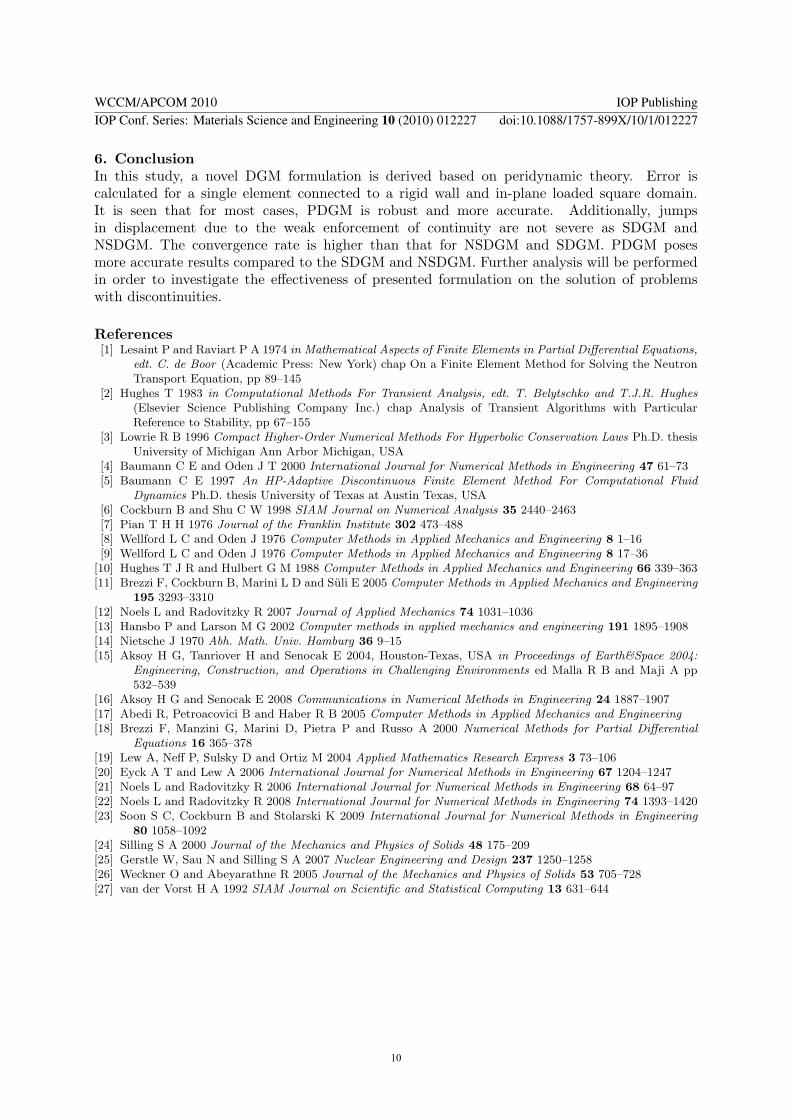


![Discontinuous Galerkin Methods - [Groupe Calcul]](https://img.pdfslide.us/doc/110x75/61fb86042e268c58cd5f2ee4/discontinuous-galerkin-methods-groupe-calcul.jpg)