Embed Size (px)
Citation preview
54 CAT-POS-E-2001 ASM
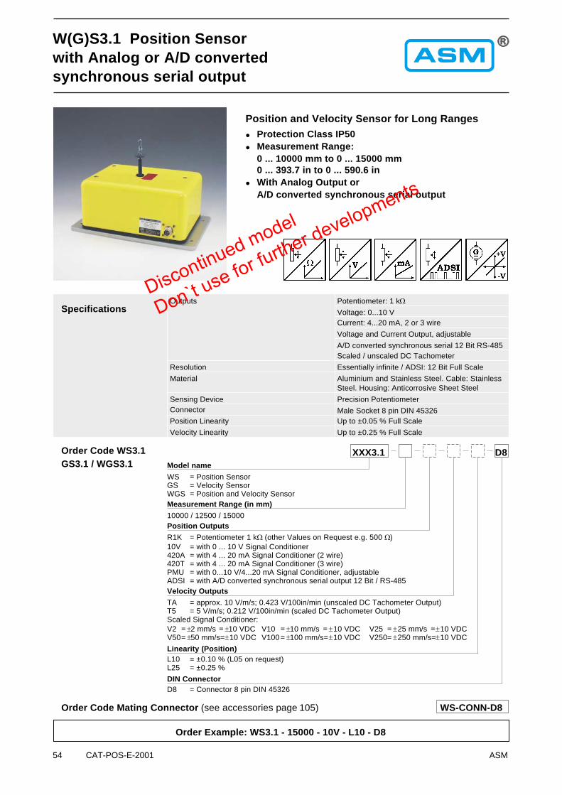
Position and Velocity Sensor for Long Ranges
� Protection Class IP50� Measurement Range:
0 ... 10000 mm to 0 ... 15000 mm0 ... 393.7 in to 0 ... 590.6 in
� With Analog Output orA/D converted synchronous serial output
SpecificationsOutputs Potentiometer: 1 k�
Voltage: 0...10 VCurrent: 4...20 mA, 2 or 3 wire
Voltage and Current Output, adjustable
A/D converted synchronous serial 12 Bit RS-485Scaled / unscaled DC Tachometer
Resolution Essentially infinite / ADSI: 12 Bit Full Scale
Material Aluminium and Stainless Steel. Cable: StainlessSteel. Housing: Anticorrosive Sheet Steel
Sensing Device Precision PotentiometerConnector Male Socket 8 pin DIN 45326Position Linearity Up to ±0.05 % Full Scale
Velocity Linearity Up to ±0.25 % Full Scale
Order Example: WS3.1 - 15000 - 10V - L10 - D8
W(G)S3.1 Position Sensorwith Analog or A/D convertedsynchronous serial output
Order Code Mating Connector (see accessories page 105) WS-CONN-D8
Order Code WS3.1
Model name
WS = Position SensorGS = Velocity SensorWGS = Position and Velocity SensorMeasurement Range (in mm)
10000 / 12500 / 15000Position Outputs
R1K = Potentiometer 1 k� (other Values on Request e.g. 500 �)10V = with 0 ... 10 V Signal Conditioner420A = with 4 ... 20 mA Signal Conditioner (2 wire)420T = with 4 ... 20 mA Signal Conditioner (3 wire)PMU = with 0...10 V/4...20 mA Signal Conditioner, adjustableADSI = with A/D converted synchronous serial output 12 Bit / RS-485Velocity Outputs
TA = approx. 10 V/m/s; 0.423 V/100in/min (unscaled DC Tachometer Output)T5 = 5 V/m/s; 0.212 V/100in/min (scaled DC Tachometer Output)Scaled Signal Conditioner:V2 = �2 mm/s = �10 VDC V10 = �10 mm/s = �10 VDC V25 = �25 mm/s =�10 VDCV50= �50 mm/s=�10 VDC V100= �100 mm/s=�10 VDC V250= �250 mm/s=�10 VDC
Linearity (Position)L10 = ±0.10 % (L05 on request)L25 = ±0.25 %
DIN ConnectorD8 = Connector 8 pin DIN 45326
D8XXX3.1GS3.1 / WGS3.1
Discontinued model
Don`t use for further developments
ASM CAT-POS-E-2001 55
Cable Forcestypical at 20 °C
Range[mm] [in]
Maximum Pull-out Force[N]
Minimum Pull-in Force[N]
10000 393.7 10.6 6.212500 492.1 8.6 5.115000 590.6 7.2 4.3
Specifications(Continuation)
Protection Class (IEC 529) IP50
Weight 5.1 kg approx.Environmental
Immunity to Interference (EMC) Refer to Output Specification
Temperature Refer to Output Specification
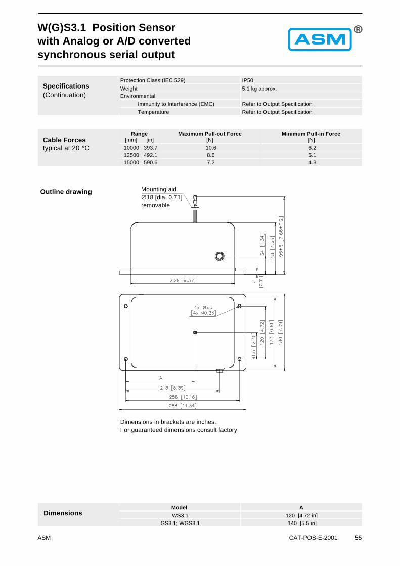
Mounting aid�18 [dia. 0.71]removable
Dimensions in brackets are inches.For guaranteed dimensions consult factory
DimensionsModel A
WS3.1 120 [4.72 in]GS3.1; WGS3.1 140 [5.5 in]
W(G)S3.1 Position Sensorwith Analog or A/D convertedsynchronous serial output
Outline drawing

56 CAT-POS-E-2001 ASM
Compact Sensor for Long Ranges
� Protection Class IP50� Measurement Range:
0 ... 15000 mm0 ... 590.6 in
� With Incremental Encoder Output
Order Example: WS3.1 - 15000 - 1 - PP530 - D8
WS3.1 Position Sensorwith Incremental Encoder
Order Code Mating Connector (see accessories page 105) WS-CONN-D8
SpecificationsOutputs Incremental Encoder Output with differential
Push-pull Circuit for reliable Data Transmission.The output is compatible with LD, HTL, TTL andCMOS.
Resolution 1 Pulse per mm; 25.4 pulses per in
Distance between Reference Pulses 1500 mmMaterial Aluminium and Stainless Steel. Cable: Stainless
steel. Housing: Anticorrosive Sheet SteelSensing Device Incremental Encoder
Connector Male Socket 8 pin DIN 45326
Linearity ±0.05 % Full Scale
Protection Class (IEC 529) IP50Weight 5.1 kg approx.
Environmental
Immunity to Interference (EMC) Refer to Output SpecificationTemperature Refer to Output Specification
Order Code WS3.1
Model Name
Measurement Range (in mm)
15000 (smaller measurement ranges included)Pulse per mm
1 = 1 Pulse per mm; 25.4 pulses per in
Output
DIN ConnectorD8 = Connector 8 pin DIN 45326
WS3.1 D8PP530incremental
ASM CAT-POS-E-2001 57
Cable Forcestypical at 20 °C
Range[mm] [in]
Maximum Pull-out Force[N]
Minimum Pull-in Force[N]
15000 590.6 7.7 4.5
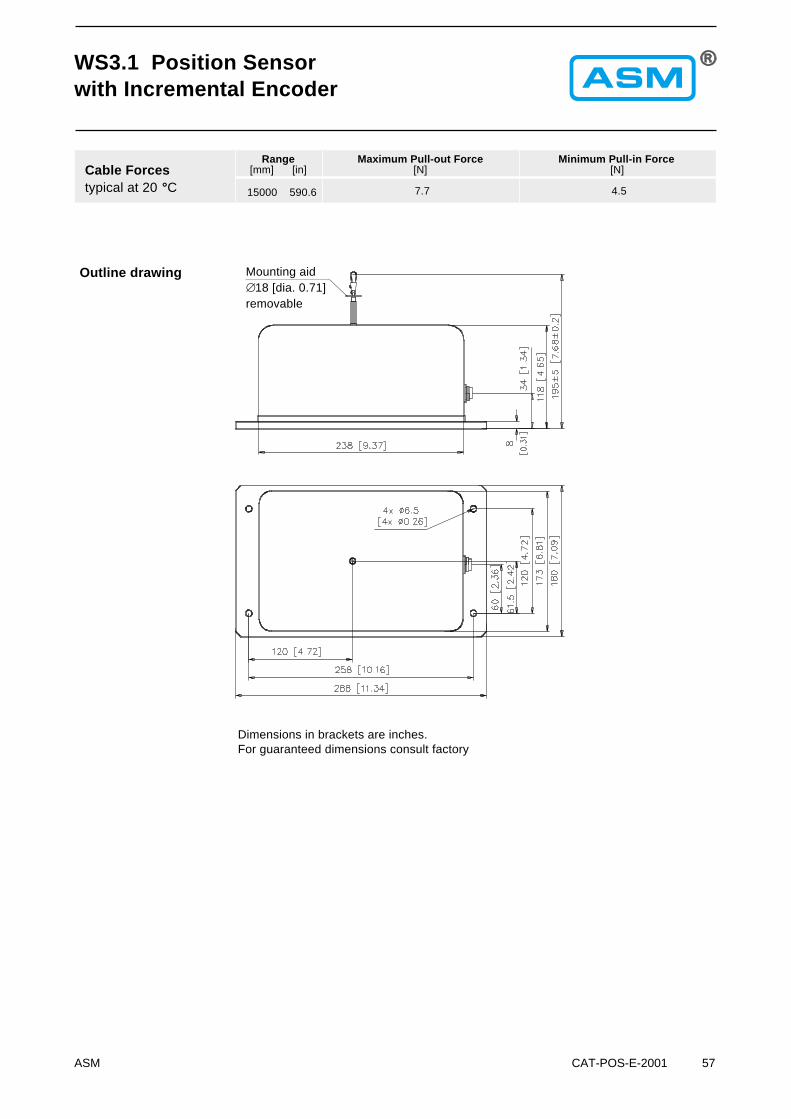
Mounting aid�18 [dia. 0.71]removable
Dimensions in brackets are inches.For guaranteed dimensions consult factory
Outline drawing
WS3.1 Position Sensorwith Incremental Encoder
ASM CAT-POS-E-2001 79
WS Position SensorsOutput Specifications R1K and 10V
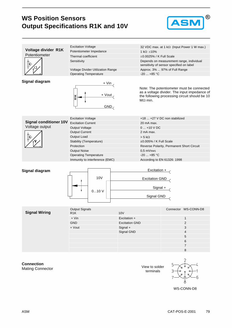
Voltage divider R1KPotentiometer
Excitation Voltage 32 VDC max. at 1 k� (Input Power 1 W max.)Potentiometer Impedance 1 k� �10%
Thermal coefficient �0.0025% / K Full Scale
Sensitivity Depends on measurement range, individualsensitivity of sensor specified on label
Voltage Divider Utilization Range Approx. 3% ... 97% of Full RangeOperating Temperature -20 ... +85 °C
Signal conditioner 10VVoltage output
Excitation Voltage +18 ... +27 V DC non stabilized
Excitation Current 20 mA max.
Output Voltage 0 ... +10 V DCOutput Current 2 mA max.
Output Load > 5 k�
Stability (Temperature) ±0.005% / K Full Scale
Protection Reverse Polarity, Permanent Short Circuit
Output Noise 0,5 mVRMS
Operating Temperature -20 ... +85 °C
Immunity to interference (EMC) According to EN 61326: 1998
Signal WiringOutput SignalsR1K 10V
Connector WS-CONN-D8
+ Vin Excitation + 1
GND Excitation GND 2
+ Vout Signal + 3Signal GND 4
5
67
8
WS-CONN-D8
View to solderterminals
Note: The potentiometer must be connectedas a voltage divider. The input impedance ofthe following processing circuit should be 10M� min.
Signal diagram
Signal diagram
+ Vout
+ Vin
GND
Excitation GND
Excitation +
Signal GND
Signal +
ConnectionMating Connector
10V
0...10 V

80 CAT-POS-E-2001 ASM
WS Position SensorsOutput Specifications 420A and 420T
Signal Conditioner420TCurrent output (3 wire)
Excitation Voltage +18...+27 V DC non stabilized
Excitation Current 40 mA max.Load Resistor 350 � max.
Output Current 4 ... 20 mA equivalent to 0 ... 100% RangeStability (Temperature) ±0.005% / K Full Scale
Protection Reverse Polarity, Permanent Short Circuit
Output Noise 0.5 mVRMS
Operating Temperature -20 ... +85 °C
Immunity to Interference According to EN 61326: 1998
Signal conditioner420ACurrent output (2 wire)
Excitation Voltage +12 ... 27 VDC non stabilized, measured at thesensor terminals
Excitation Current 35 mA max.
Output Current 4 ... 20 mA equivalent to 0 ... 100% RangeStability(Temperature) ±0.01% / K Full Scale
Protection Reverse Polarity, Permanent Short Circuit
Output Noise 0.5 mVRMS
Operating Temperature -20 ... +85 °C
Immunity to Interference (EMC) According to EN 61326: 1998
Signal WiringOutput Signals420A 420T
Connector WS-CONN-D8
Signal + Excitation + 1Signal – Excitation GND 2
Signal + 3
45
6
78
WS-CONN-D8
View to solderterminals
ConnectionMating Connector
Signal +
Signal –
420A
4...20 mA
420T
4...20 mA
Excitation +
Signal +
Excitation GND
Signal Diagram
Signal diagram
ASM CAT-POS-E-2001 81
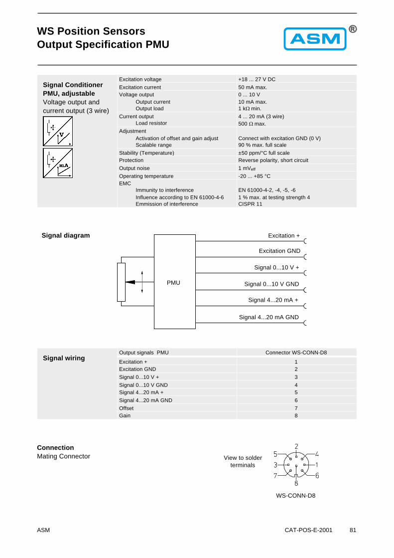
Signal ConditionerPMU, adjustableVoltage output andcurrent output (3 wire)
Excitation voltage +18 ... 27 V DC
Excitation current 50 mA max.Voltage output
Output currentOutput load
0 ... 10 V10 mA max.1 k� min.
Current outputLoad resistor
4 ... 20 mA (3 wire)500 � max.
AdjustmentActivation of offset and gain adjustScalable range
Connect with excitation GND (0 V)90 % max. full scale
Stability (Temperature) ±50 ppm/°C full scaleProtection Reverse polarity, short circuit
Output noise 1 mVeff
Operating temperature -20 ... +85 °CEMC
Immunity to interferenceInfluence according to EN 61000-4-6Emmission of interference
EN 61000-4-2, -4, -5, -61 % max. at testing strength 4CISPR 11
Signal wiringOutput signals PMU Connector WS-CONN-D8
Excitation + 1Excitation GND 2
Signal 0...10 V + 3
Signal 0...10 V GND 4Signal 4...20 mA + 5
Signal 4...20 mA GND 6
Offset 7Gain 8
Signal diagram
WS Position SensorsOutput Specification PMU
WS-CONN-D8
View to solderterminals
ConnectionMating Connector
Excitation +
Excitation GND
Signal 0...10 V +
Signal 0...10 V GND
Signal 4...20 mA +
Signal 4...20 mA GND
PMU
82 CAT-POS-E-2001 ASM
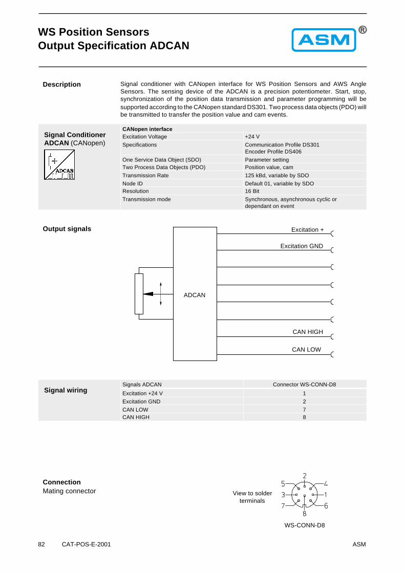
Signal ConditionerADCAN (CANopen)
CANopen interfaceExcitation Voltage +24 V
Specifications Communication Profile DS301Encoder Profile DS406
One Service Data Object (SDO) Parameter settingTwo Process Data Objects (PDO) Position value, cam
Transmission Rate 125 kBd, variable by SDO
Node ID Default 01, variable by SDOResolution 16 Bit
Transmission mode Synchronous, asynchronous cyclic ordependant on event
Signal conditioner with CANopen interface for WS Position Sensors and AWS AngleSensors. The sensing device of the ADCAN is a precision potentiometer. Start, stop,synchronization of the position data transmission and parameter programming will besupported according to the CANopen standard DS301. Two process data objects (PDO) willbe transmitted to transfer the position value and cam events.
Description
Signal wiringSignals ADCAN Connector WS-CONN-D8
Excitation +24 V 1
Excitation GND 2
CAN LOW 7CAN HIGH 8
Output signals
WS-CONN-D8
View to solderterminals
ConnectionMating connector
Excitation +
Excitation GND
CAN LOW
CAN HIGH
ADCAN
WS Position SensorsOutput Specification ADCAN
ASM CAT-POS-E-2001 83
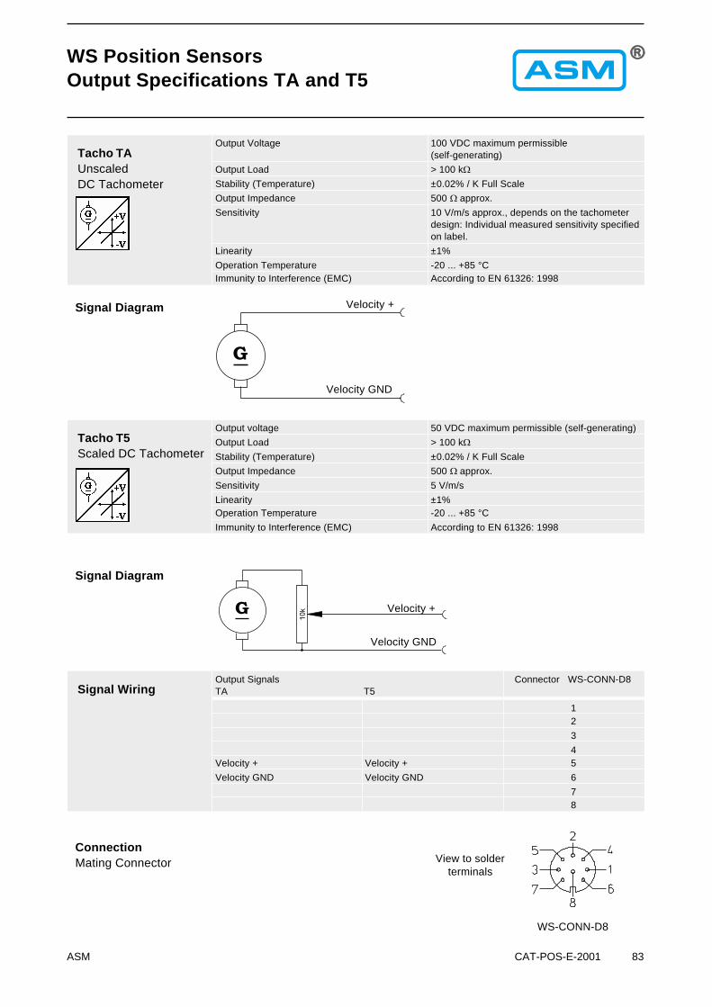
WS Position SensorsOutput Specifications TA and T5
Tacho TAUnscaledDC Tachometer
Output Voltage 100 VDC maximum permissible(self-generating)
Output Load > 100 k�
Stability (Temperature) ±0.02% / K Full Scale
Output Impedance 500 � approx.
Sensitivity 10 V/m/s approx., depends on the tachometerdesign: Individual measured sensitivity specifiedon label.
Linearity ±1%
Operation Temperature -20 ... +85 °CImmunity to Interference (EMC) According to EN 61326: 1998
Tacho T5Scaled DC Tachometer
Output voltage 50 VDC maximum permissible (self-generating)
Output Load > 100 k�
Stability (Temperature) ±0.02% / K Full Scale
Output Impedance 500 � approx.
Sensitivity 5 V/m/s
Linearity ±1%Operation Temperature -20 ... +85 °C
Immunity to Interference (EMC) According to EN 61326: 1998
Signal WiringOutput SignalsTA T5
Connector WS-CONN-D8
12
3
4Velocity + Velocity + 5
Velocity GND Velocity GND 6
78
WS-CONN-D8
View to solderterminals
ConnectionMating Connector
Velocity +
Velocity GND
Velocity GND
Velocity +
Signal Diagram
Signal Diagram
84 CAT-POS-E-2001 ASM
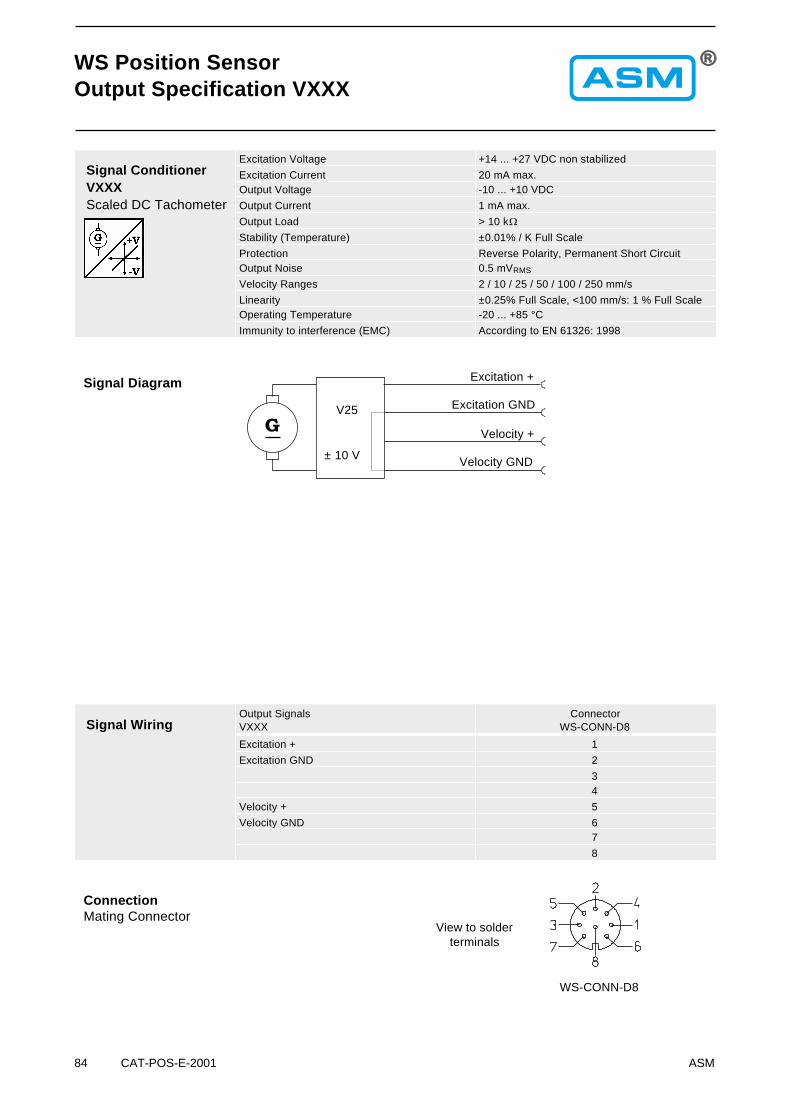
Signal ConditionerVXXXScaled DC Tachometer
Excitation Voltage +14 ... +27 VDC non stabilized
Excitation Current 20 mA max.Output Voltage -10 ... +10 VDC
Output Current 1 mA max.
Output Load > 10 k�
Stability (Temperature) ±0.01% / K Full Scale
Protection Reverse Polarity, Permanent Short CircuitOutput Noise 0.5 mVRMS
Velocity Ranges 2 / 10 / 25 / 50 / 100 / 250 mm/s
Linearity ±0.25% Full Scale, <100 mm/s: 1 % Full ScaleOperating Temperature -20 ... +85 °C
Immunity to interference (EMC) According to EN 61326: 1998
WS Position SensorOutput Specification VXXX
Signal WiringOutput SignalsVXXX
ConnectorWS-CONN-D8
Excitation + 1
Excitation GND 2
34
Velocity + 5
Velocity GND 67
8
WS-CONN-D8
View to solderterminals
ConnectionMating Connector
Signal Diagram Excitation +
Excitation GND
Velocity GND
Velocity +
V25
± 10 V

88 CAT-POS-E-2001 ASM
WS Position SensorsOutput Specification ADSI
The sensing device of the ADSI is a precision potentiometer. The position information isgiven by an analog/digital converter output serialized as a data word. Data transmissiontakes place by means of the signals CLOCK and DATA. The processing unit (PLC, Micro-computer) sends pulse sequences which clock the data transmission with the requiredtransfer rate. With the first falling edge of a pulse sequence the position of the sensor isrecorded and stored. The following rising edges control the bit-by-bit A/D conversion,encoding and output of the data word.After a delay time the next new position information will be transmitted.
Signal ConditionerADSIA/D convertedsynchronous serial
Output EIA RS-422, RS-485, short-circuit proof
Excitation Voltage 11 ... 27 VDC
Excitation Current 200 mA max.Clock Frequency 70 ... 500 kHz
Code Gray Code, Continuous Progression
Delay between Pulse Trains T=30 µs min.Resolution 12 Bit (4096 Counts) Full Scale
Stability (Temperature) ±0.005% / K Full Scale
Operation Temperature -20 ... +85 °CImmunity to Interference (EMC) According to EN 61326: 1998
RecommendedProcessingInput Circuit
GND (0V)
Sensor Circuit Cable Subsequent Circuit
Data Format(Train of 26 Pulses)
WS-CONN-D8
Mating ConnectorView to solder terminals
Cable Length Baud Rate
50 m 300 kHz200 m 100 kHz
Note:Extension of the cable length will reduce themaximum transmission rate. The signalsCLOCK/CLOCK and DATA/DATA must beconnected in a twisted pair cable, shieldedper pair and common.
Description
� Resolution 12 Bit, Data Transmission synchronous serial� No Loss of Data at Power-down� Easy to Connect to PLC’s with SSI Input Circuit
Signal Wiring /Connection
Signal name Connector Pin
Excitation + 1
Excitation GND (0V) 2CLOCK 3
CLOCK 4
DATA 5DATA 6
Screen not connected
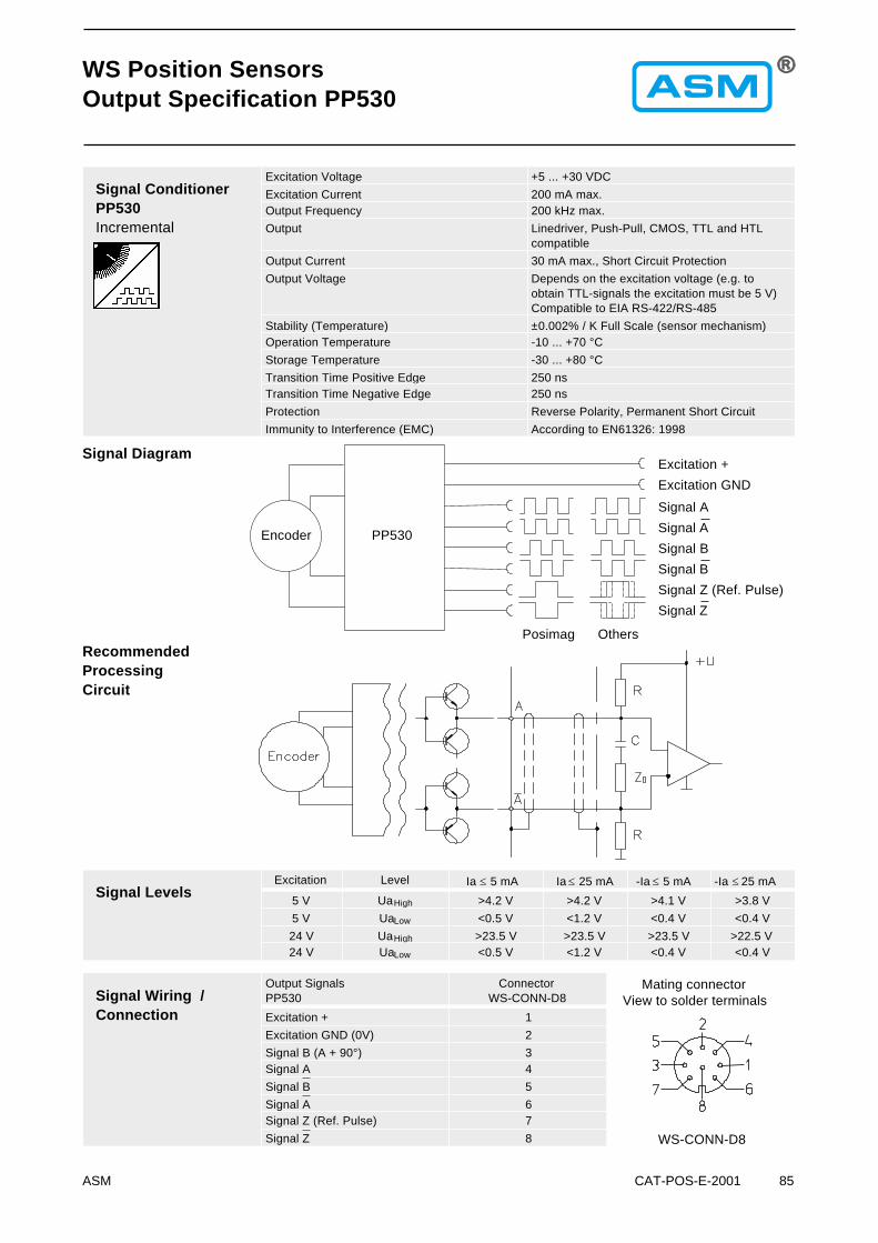
ASM CAT-POS-E-2001 85
WS Position SensorsOutput Specification PP530
Signal ConditionerPP530Incremental
Excitation Voltage +5 ... +30 VDC
Excitation Current 200 mA max.Output Frequency 200 kHz max.
Output Linedriver, Push-Pull, CMOS, TTL and HTLcompatible
Output Current 30 mA max., Short Circuit Protection
Output Voltage Depends on the excitation voltage (e.g. toobtain TTL-signals the excitation must be 5 V)Compatible to EIA RS-422/RS-485
Stability (Temperature) ±0.002% / K Full Scale (sensor mechanism)Operation Temperature -10 ... +70 °C
Storage Temperature -30 ... +80 °C
Transition Time Positive Edge 250 nsTransition Time Negative Edge 250 ns
Protection Reverse Polarity, Permanent Short Circuit
Immunity to Interference (EMC) According to EN61326: 1998
Signal LevelsExcitation Level Ia � 5 mA Ia � 25 mA -Ia � 5 mA -Ia � 25 mA
5 V UaHigh >4.2 V >4.2 V >4.1 V >3.8 V
5 V UaLow <0.5 V <1.2 V <0.4 V <0.4 V
24 V UaHigh >23.5 V >23.5 V >23.5 V >22.5 V24 V UaLow <0.5 V <1.2 V <0.4 V <0.4 V
RecommendedProcessingCircuit
Excitation +
Excitation GND
Signal Diagram
Signal A
Signal B
Signal A
Signal B
Signal Z (Ref. Pulse)
Signal Z
Encoder PP530
Signal Wiring /Connection
Output SignalsPP530
ConnectorWS-CONN-D8
Excitation + 1
Excitation GND (0V) 2
Signal B (A + 90°) 3Signal A 4
Signal B 5
Signal A 6Signal Z (Ref. Pulse) 7
Signal Z 8 WS-CONN-D8
Mating connectorView to solder terminals
Posimag Others