Embed Size (px)
Citation preview


Dis
asse
mbl
y
Ove
rvie
w2
-1
2.Disassembly
Cha
pter
2: D
isas
sem
bly
This
cha
pter
pro
vide
s st
ep-b
y-st
ep in
stru
ctio
ns f
or d
isas
sem
blin
g th
e X7
200
serie
s no
tebo
ok’s
par
ts a
nd s
ubsy
stem
s.W
hen
it co
mes
to re
asse
mbl
y, re
vers
e th
e pr
oced
ures
(unl
ess o
ther
wis
e in
dica
ted)
.
We
sugg
est y
ou c
ompl
etel
y re
view
any
pro
cedu
re b
efor
e yo
u ta
ke th
e co
mpu
ter a
part.
Proc
edur
es su
ch a
s upg
radi
ng/re
plac
ing
the
RA
M, o
ptic
al d
evic
e an
d ha
rd d
isk
are
incl
uded
in th
e Use
r’s M
anua
l but
are
repe
ated
her
e fo
r you
r con
veni
ence
.
To m
ake
the
disa
ssem
bly
proc
ess
easi
er e
ach
sect
ion
may
hav
e a
box
in th
e pa
ge m
argi
n. In
form
atio
n co
ntai
ned
unde
rth
e fig
ure
# w
ill g
ive
a sy
nops
is o
f the
sequ
ence
of p
roce
dure
s inv
olve
d in
the
disa
ssem
bly
proc
edur
e. A
box
with
a
lists
the
rele
vant
par
ts y
ou w
ill h
ave
afte
r the
dis
asse
mbl
y pr
oces
s is c
ompl
ete.
Not
e: T
he p
arts
list
ed w
ill b
e fo
r the
dis
-as
sem
bly
proc
edur
e lis
ted
ON
LY, a
nd n
ot a
ny p
revi
ous d
isas
sem
bly
step
(s) r
equi
red.
Ref
er to
the
part
list f
or th
e pr
evi-
ous d
isas
sem
bly
proc
edur
e. T
he a
mou
nt o
f scr
ews
you
shou
ld b
e le
ft w
ith w
ill b
e lis
ted
here
als
o.
A b
ox w
ith a
w
ill a
lso
prov
ide
any
poss
ible
hel
pful
info
rmat
ion.
A b
ox w
ith a
c
onta
ins w
arni
ngs.
An
exam
ple
of th
ese
type
s of b
oxes
are
show
n in
the
side
bar.

Dis
asse
mbl
y
2-
2O
verv
iew
2.Disassembly
NO
TE:
All
disa
ssem
bly
proc
edur
es a
ssum
e tha
t the
syst
em is
turn
ed O
FF, a
nd d
isco
nnec
ted
from
any
pow
er su
pply
(the
batte
ry is
rem
oved
too)
.
The
follo
win
g to
ols a
re re
com
men
ded
whe
n w
orki
ng o
n th
e no
tebo
ok P
C:
Con
nect
ions
with
in th
e co
mpu
ter a
re o
ne o
f fou
r typ
es:
Lock
ing
colla
r soc
kets
for r
ibbo
n co
nnec
tors
To re
leas
e the
se co
nnec
tors
, use
a sm
all f
lat-h
ead
scre
wdr
iver
toge
ntly
pry
the
lock
ing
colla
r aw
ay fr
om it
s bas
e. W
hen
repl
ac-
ing
the
conn
ectio
n, m
ake
sure
the
conn
ecto
r is
orie
nted
in th
esa
me
way
. The
pin
1 si
de is
usu
ally
not
indi
cate
d.
Pres
sure
sock
ets f
or m
ulti-
wire
con
nect
ors
To r
elea
se th
is co
nnec
tor
type
, gra
sp it
at i
ts h
ead
and
gent
lyro
ck it
from
sid
e to
sid
e as
you
pul
l it o
ut. D
o no
t pul
l on
the
wire
s th
emse
lves
. Whe
n re
plac
ing
the
conn
ectio
n, d
o no
t try
tofo
rce
it. T
he so
cket
onl
y fit
s one
way
.
Pres
sure
sock
ets f
or ri
bbon
con
nect
ors
To re
leas
e th
ese
conn
ecto
rs, u
se a
smal
l pai
r of n
eedl
e-no
se p
li-er
s to
gen
tly li
ft th
e co
nnec
tor a
way
from
its
sock
et. W
hen
re-
plac
ing
the
conn
ectio
n, m
ake
sure
the
conn
ecto
r is
orie
nted
inth
e sa
me
way
. The
pin
1 sid
e is
usu
ally
not
indi
cate
d.
Boa
rd-to
-boa
rd o
r mul
ti-pi
n so
cket
sTo
sep
arat
e th
e bo
ards
, gen
tly r
ock
them
fro
m s
ide
to s
ide
asyo
u pu
ll th
em a
part.
If th
e co
nnec
tion
is v
ery
tight
, use
a s
mal
lfla
t-hea
d sc
rew
driv
er -
use
just
eno
ugh
forc
e to
star
t.

Dis
asse
mbl
y
Ove
rvie
w2
-3
2.Disassembly
The
follo
win
g pr
ecau
tions
are
a re
min
der.
To a
void
per
sona
l inj
ury
or d
amag
e to
the
com
pute
r whi
le p
erfo
rmin
g a
re-
mov
al a
nd/o
r rep
lace
men
t job
, tak
e th
e fo
llow
ing
prec
autio
ns:
1.D
on't
drop
it. P
erfo
rm y
our r
epai
rs a
nd/o
r upg
rade
s on
a s
tabl
e su
rface
. If t
he c
ompu
ter f
alls
, the
cas
e an
d ot
her
com
pone
nts
coul
d be
dam
aged
.2.
Don
't ov
erhe
at it
. Not
e th
e pr
oxim
ity o
f any
hea
ting
elem
ents
. Kee
p th
e co
mpu
ter o
ut o
f dire
ct s
unlig
ht.
3.Av
oid
inte
rfer
ence
. Not
e th
e pr
oxim
ity o
f any
hig
h ca
paci
ty tr
ansf
orm
ers,
ele
ctric
mot
ors,
and
oth
er s
trong
mag
-ne
tic fi
elds
. The
se c
an h
inde
r pro
per p
erfo
rman
ce a
nd d
amag
e co
mpo
nent
s an
d/or
dat
a. Y
ou s
houl
d al
so m
onito
r th
e po
sitio
n of
mag
netiz
ed to
ols
(i.e.
scr
ewdr
iver
s).
4.K
eep
it dr
y. T
his
is a
n el
ectri
cal a
pplia
nce.
If w
ater
or a
ny o
ther
liqu
id g
ets
into
it, t
he c
ompu
ter c
ould
be
badl
y da
mag
ed.
5.B
e ca
refu
l with
pow
er. A
void
acc
iden
tal s
hock
s, d
isch
arge
s or
exp
losi
ons.
6.Pe
riphe
rals
– T
urn
off a
nd d
etac
h an
y pe
riphe
rals
.7.
Bew
are
of s
tatic
dis
char
ge. I
Cs,
suc
h as
the
CPU
and
mai
n su
ppor
t chi
ps, a
re v
ulne
rabl
e to
sta
tic e
lect
ricity
. B
efor
e ha
ndlin
g an
y pa
rt in
the
com
pute
r, di
scha
rge
any
stat
ic e
lect
ricity
insi
de th
e co
mpu
ter.
Whe
n ha
ndlin
g a
prin
ted
circ
uit b
oard
, do
not u
se g
love
s or
oth
er m
ater
ials
whi
ch a
llow
sta
tic e
lect
ricity
bui
ldup
. We
sugg
est t
hat
you
use
an a
nti-s
tatic
wris
t stra
p in
stea
d.8.
Bew
are
of c
orro
sion
. As
you
perfo
rm y
our j
ob, a
void
touc
hing
any
con
nect
or le
ads.
Eve
n th
e cl
eane
st h
ands
pro
-du
ce o
ils w
hich
can
attr
act c
orro
sive
ele
men
ts.
9.K
eep
your
wor
k en
viro
nmen
t cle
an. T
obac
co s
mok
e, d
ust o
r oth
er a
ir-bo
rn p
artic
ulat
e m
atte
r is
ofte
n at
tract
ed
to c
harg
ed s
urfa
ces,
redu
cing
per
form
ance
.10
.K
eep
trac
k of
the
com
pone
nts.
Whe
n re
mov
ing
or re
plac
ing
any
part,
be
care
ful n
ot to
leav
e sm
all p
arts
, suc
h as
sc
rew
s, lo
ose
insi
de th
e co
mpu
ter.
Do
not a
pply
cle
aner
dire
ctly
to th
e co
mpu
ter,
use
a so
ft cl
ean
clot
h.D
o no
t use
vol
atile
(pet
role
um d
istil
late
s) o
r abr
asiv
e cl
eane
rs o
n an
y pa
rt of
the
com
pute
r.

Dis
asse
mbl
y
Rem
ovin
g th
e B
atte
ry2
-5
2.Disassembly
1.Tu
rn th
e co
mpu
ter o
ff, a
nd tu
rn it
ove
r.2.
Loos
en s
crew
s -
(Fig
ure
1a)a
nd c
aref
ully
lift
the
batte
ry
up
(Fig
ure
1b).
3.R
emov
e th
e ba
ttery
fr
om th
e ba
ttery
bay
(Fig
ure
1c).
a.
4
b.
23
1
c.
4
Figu
re 1
Bat
tery
Rem
oval
Dis
asse
mbl
y
2-
12R
emov
ing
the
Key
boar
d
2.Disassembly
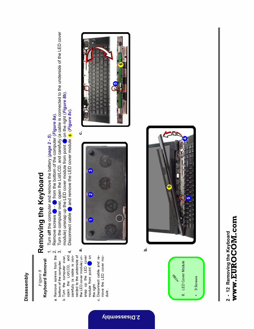
1.Tu
rn o
ff th
e co
mpu
ter a
nd re
mov
e th
e ba
ttery
(pag
e 2
- 5).
2.R
emov
e sc
rew
s -
from
the
botto
m o
f the
com
pute
r (Fi
gure
8a)
.3.
Turn
the
com
pute
r ove
r, op
en th
e Li
d/LC
D, a
nd c
aref
ully
(a c
able
is c
onne
cted
to th
e un
ders
ide
of th
e LE
D c
over
m
odul
e) u
nsna
p up
the
LED
cov
er m
odul
e fro
m p
oint
o
n th
e rig
ht (F
igur
e 8b
).4.
Dis
conn
ect c
able
a
nd re
mov
e th
e LE
D c
over
mod
ule
(Fig
ure
8c).
Figu
re 8
Key
boar
d R
emov
al
a. b.
23
4
1
c.
5
5
6
6

Dis
asse
mbl
y
Rem
ovin
g th
e K
eybo
ard
2-
13
2.Disassembly
5.R
emov
e sc
rew
s -
from
the
keyb
oard
(Fig
ure
9d).
6.C
aref
ully
lift
the
keyb
oard
up,
bei
ng c
aref
ul n
ot to
ben
d th
e ke
yboa
rd ri
bbon
cab
le
. D
isco
nnec
t the
key
boar
d rib
bon
cabl
e fr
om th
e lo
ckin
g co
llar s
ocke
t (F
igur
e 9e
).7.
Rem
ove
the
keyb
oard
(F
igur
e 9f
).
d.f.
e.
78
9
Keyb
oard
Tab
s
(f)
Figu
re 9
Key
boar
d R
emov
al
(con
t’d.)

Dis
asse
mbl
y
2-
14R
emov
ing
the
Key
boar
d
2.Disassembly
8.R
emov
e sc
rew
s -
from
the
keyb
oard
shi
eldi
ng p
late
(F
igur
e 10
g).
9.Li
ft th
e ke
yboa
rd s
hiel
ding
pla
te u
p in
the
dire
ctio
n of
the
arro
w
(Fig
ure
10h)
.10
.R
emov
e th
e ke
yboa
rd s
hiel
ding
pla
te
(Fig
ure
10i).
g.h.
2 1 i.
Figu
re 1
0K
eybo
ard
Rem
oval
(co
nt’d
.)

Dis
asse
mbl
y
Rem
ovin
g th
e K
eybo
ard
2-
15
2.Disassembly
1.W
hen
re-in
serti
ng th
e ke
yboa
rd s
hiel
ding
pla
te
mak
e su
re y
ou in
sert
it by
slid
ing
it in
to p
ositi
on a
t an
angl
e as
ill
ustra
ted
by a
rrow
b
elow
, and
pre
ss it
dow
n in
to p
ositi
on (F
igur
e 11
a).
2.S
ecur
e th
e pl
ate
with
scr
ews
- (F
igur
e 11
b).
Figu
re 1
1K
eybo
ard
Shie
ldin
g Pl
ate
Inse
rtio
n
14
2
3
5
a.b.
Dis
asse
mbl
y
2-
18R
emov
ing
the
Syst
em M
emor
y (R
AM
)
2.Disassembly
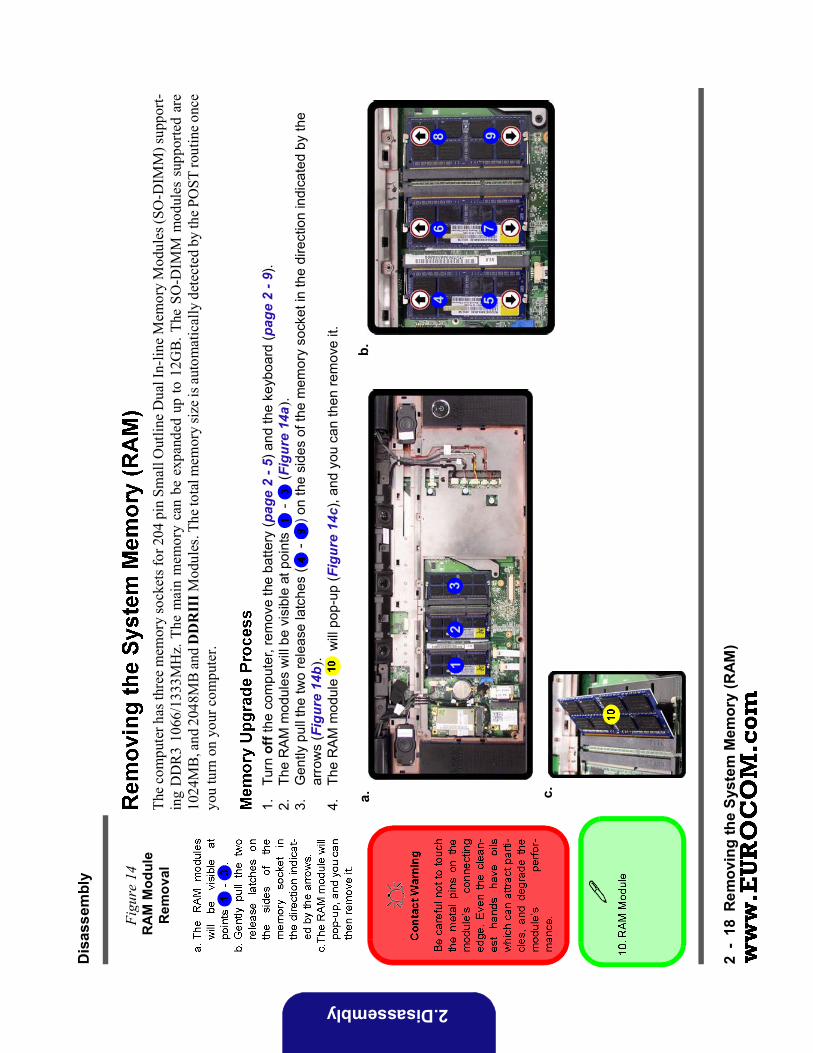
The
com
pute
r has
thre
e m
emor
y so
cket
s for
204
pin
Sm
all O
utlin
e D
ual I
n-lin
e M
emor
y M
odul
es (S
O-D
IMM
) sup
port-
ing
DD
R3
1066
/133
3MH
z. T
he m
ain
mem
ory
can
be e
xpan
ded
up to
12G
B. T
he S
O-D
IMM
mod
ules
sup
porte
d ar
e10
24M
B, a
nd 2
048M
B a
nd D
DR
III M
odul
es. T
he to
tal m
emor
y siz
e is a
utom
atic
ally
det
ecte
d by
the P
OST
rout
ine o
nce
you
turn
on
your
com
pute
r.
1.Tu
rn o
ff th
e co
mpu
ter,
rem
ove
the
batte
ry (p
age
2 - 5
) and
the
keyb
oard
(pag
e 2
- 9).
2.Th
e R
AM
mod
ules
will
be
visi
ble
at p
oint
s -
(Fig
ure
14a)
.3.
Gen
tly p
ull t
he tw
o re
leas
e la
tche
s (
- ) o
n th
e si
des
of th
e m
emor
y so
cket
in th
e di
rect
ion
indi
cate
d by
the
arro
ws
(Fig
ure
14b)
.4.
The
RA
M m
odul
e w
ill p
op-u
p (F
igur
e 14
c), a
nd y
ou c
an th
en re
mov
e it.
Figu
re 1
4 R
AM
Mod
ule
Rem
oval
a.
24
1
b.
3
5
6 7
8 9
c.

Dis
asse
mbl
y
Rem
ovin
g th
e Sy
stem
Mem
ory
(RA
M)
2-
19
2.Disassembly
5.P
ull t
he la
tche
s to
rele
ase
the
seco
nd a
nd th
ird m
odul
es if
nec
essa
ry.
6.In
sert
a ne
w m
odul
e ho
ldin
g it
at a
bout
a 3
0° a
ngle
and
fit t
he c
onne
ctor
s fir
mly
into
the
mem
ory
slot
.7.
The
mod
ule’
s pi
n al
ignm
ent w
ill a
llow
it to
onl
y fit
one
way
. Mak
e su
re th
e m
odul
e is
sea
ted
as fa
r int
o th
e sl
ot a
s it
will
go.
DO
NO
T FO
RC
E th
e m
odul
e; it
sho
uld
fit w
ithou
t muc
h pr
essu
re.
8.P
ress
the
mod
ule
in a
nd d
own
tow
ards
the
mai
nboa
rd u
ntil
the
slot
leve
rs c
lick
into
pla
ce to
sec
ure
the
mod
ule.
9.R
epla
ce th
e ba
y co
ver a
nd s
crew
s (m
ake
sure
you
reco
nnec
t the
fan
cabl
e be
fore
scr
ewin
g do
wn
the
bay
cove
r).
10.
Res
tart
the
com
pute
r to
allo
w th
e B
IOS
to re
gist
er th
e ne
w m
emor
y co
nfig
urat
ion
as it
sta
rts u
p.