Embed Size (px)
Citation preview
−1− WK 460 580
WK460 580
04.2001r.
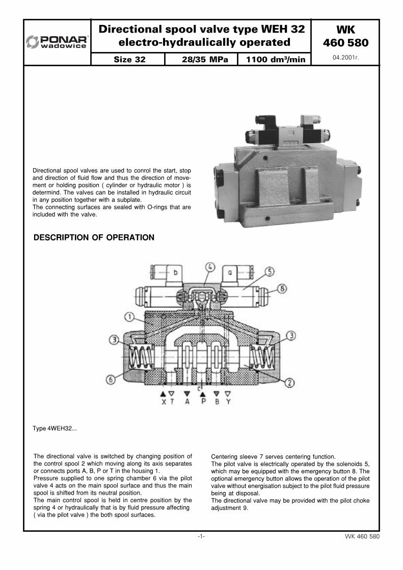
Directional spool valve type WEH 32 electro−hydraulically operated
Directional spool valves are used to conrol the start, stopand direction of fluid flow and thus the direction of move-ment or holding position ( cylinder or hydraulic motor ) isdetermind. The valves can be installed in hydraulic circuitin any position together with a subplate.The connecting surfaces are sealed with O-rings that areincluded with the valve.
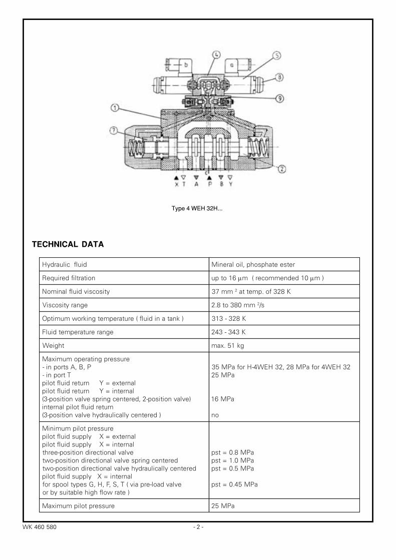
DESCRIPTION OF OPERATION
The directional valve is switched by changing position ofthe control spool 2 which moving along its axis separatesor connects ports A, B, P or T in the housing 1.Pressure supplied to one spring chamber 6 via the pilotvalve 4 acts on the main spool surface and thus the mainspool is shifted from its neutral position.The main control spool is held in centre position by thespring 4 or hydraulically that is by fluid pressure affecting( via the pilot valve ) the both spool surfaces.
Centering sleeve 7 serves centering function.The pilot valve is electrically operated by the solenoids 5,which may be equipped with the emergency button 8. Theoptional emergency button allows the operation of the pilotvalve without energisation subject to the pilot fluid pressurebeing at disposal.The directional valve may be provided with the pilot chokeadjustment 9.
Type 4WEH32...
Size 32 28/35 MPa 1100 dm3/min
− 2 −WK 460 580
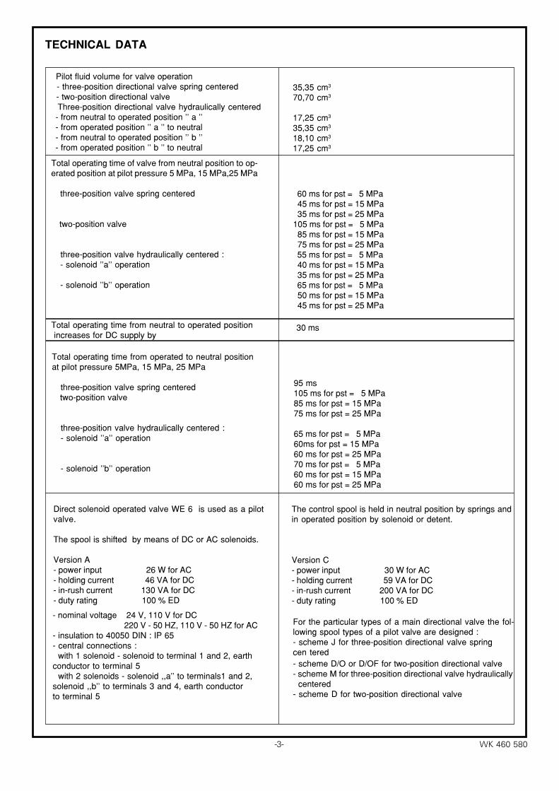
Type 4 WEH 32H...
TECHNICAL DATA
diulfciluardyH retseetahpsohp,liolareniM
noitartlifderiuqeR 61otpu µ 01dednemmocer(m µ )m
ytisocsivdiulflanimoN mm73 2 K823fo.pmetta
egnarytisocsiV mm083ot8.2 2 s/
)knatanidiulf(erutarepmetgnikrowmumitpO K823−313
egnarerutarepmetdiulF K343−342
thgieW gk15.xam
erusserpgnitarepomumixaMP,B,Astropni−
Ttropni−lanretxe=Ynruterdiulftoliplanretni=Ynruterdiulftolip
)evlavnoitisop−2,deretnecgnirpsevlavnoitisop−3(nruterdiulftoliplanretni
)deretnecyllaciluardyhevlavnoitisop−3(
23HEW4rofaPM82,23HEW4−HrofaPM53aPM52
aPM61
on
erusserptolipmuminiMlanretxe=Xylppusdiulftoliplanretni=Xylppusdiulftolip
evlavlanoitceridnoitisop−eerhtderetnecgnirpsevlavlanoitceridnoitisop−owt
deretnecyllaciluardyhevlavlanoitceridnoitisop−owtlanretni=Xylppusdiulftolip
evlavdaol−erpaiv(T,S,F,H,Gsepytloopsrof)etarwolfhgihelbatiusybro
aPM8.0=tspaPM0.1=tspaPM5.0=tsp
aPM54.0=tsp
erusserptolipmumixaM aPM52
−3− WK 460 580
TECHNICAL DATA
35,35 cm3
70,70 cm3
17,25 cm3
35,35 cm3
18,10 cm3
17,25 cm3
Total operating time of valve from neutral position to op- erated position at pilot pressure 5 MPa, 15 MPa,25 MPa
three-position valve spring centered
two-position valve
three-position valve hydraulically centered : - solenoid ''a'' operation
- solenoid ''b'' operation
60 ms for pst = 5 MPa 45 ms for pst = 15 MPa 35 ms for pst = 25 MPa 105 ms for pst = 5 MPa 85 ms for pst = 15 MPa 75 ms for pst = 25 MPa 55 ms for pst = 5 MPa 40 ms for pst = 15 MPa 35 ms for pst = 25 MPa 65 ms for pst = 5 MPa 50 ms for pst = 15 MPa 45 ms for pst = 25 MPa
30 msTotal operating time from neutral to operated position increases for DC supply by
95 ms105 ms for pst = 5 MPa85 ms for pst = 15 MPa75 ms for pst = 25 MPa
65 ms for pst = 5 MPa60ms for pst = 15 MPa60 ms for pst = 25 MPa70 ms for pst = 5 MPa60 ms for pst = 15 MPa60 ms for pst = 25 MPa
Total operating time from operated to neutral positionat pilot pressure 5MPa, 15 MPa, 25 MPa
three-position valve spring centered two-position valve
three-position valve hydraulically centered : - solenoid ''a'' operation
- solenoid ''b'' operation
Direct solenoid operated valve WE 6 is used as a pilotvalve.
The spool is shifted by means of DC or AC solenoids.
Version A- power input 26 W for AC- holding current 46 VA for DC- in-rush current 130 VA for DC- duty rating 100 % ED
The control spool is held in neutral position by springs andin operated position by solenoid or detent.
Version C- power input 30 W for AC- holding current 59 VA for DC- in-rush current 200 VA for DC- duty rating 100 % ED
- nominal voltage 24 V, 110 V for DC 220 V - 50 HZ, 110 V - 50 HZ for AC- insulation to 40050 DIN : IP 65- central connections : with 1 solenoid - solenoid to terminal 1 and 2, earthconductor to terminal 5 with 2 solenoids - solenoid ,,a'' to terminals1 and 2,solenoid ,,b'' to terminals 3 and 4, earth conductorto terminal 5
For the particular types of a main directional valve the fol-lowing spool types of a pilot valve are designed :- scheme J for three-position directional valve springcen tered- scheme D/O or D/OF for two-position directional valve- scheme M for three-position directional valve hydraulically centered- scheme D for two-position directional valve
Pilot fluid volume for valve operation - three-position directional valve spring centered - two-position directional valve Three-position directional valve hydraulically centered - from neutral to operated position '' a '' - from operated position '' a '' to neutral - from neutral to operated position '' b '' - from operated position '' b '' to neutral
− 4 −WK 460 580
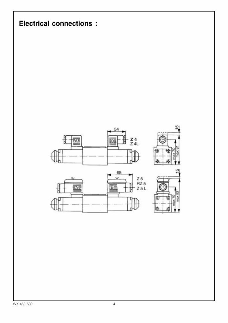
Electrical connections :
−5− WK 460 580
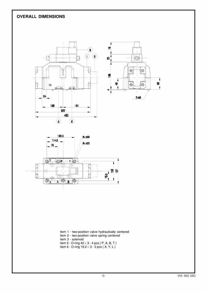
OVERALL DIMENSIONS
item 1 - two-position valve hydraulically centereditem 2 - two-position valve spring centereditem 3 - solenoiditem 5 - O-ring 42 × 3 - 4 pcs ( P, A, B, T )item 6 - O-ring 19.2 × 3 - 3 pcs ( X, Y, L )
− 6 −WK 460 580
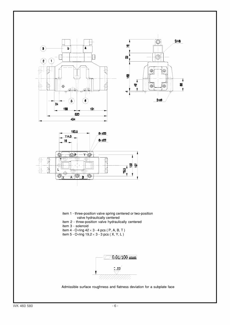
Admissible surface roughness and flatness deviation for a subplate face
item 1 - three-position valve spring centered or two-position valve hydraulically centereditem 2 - three-position valve hydraulically centereditem 3 - solenoiditem 4 - O-ring 42 × 3 - 4 pcs ( P, A, B, T )item 5 - O-ring 19,2 × 3 - 3 pcs ( X, Y, L )
−7− WK 460 580
0
∆p
(MPa
)
0,8
1,0
1,2
0,6
0,4
0,2
360120 480 720600240Q (dm / min)
0
∆p
(MPa
)
0,8
1,0
1,2
0,6
0,4
0,2
360120 480 720600240Q (dm / min)3 3
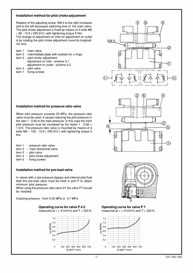
Installation method for pilot choke adjustment
Rotation of the adjusting screw SW 6 to the right increasesand to the left decreases switching time of the main valve.The pilot choke adjustment is fixed by means of 4 bolts M5× 80 - 10.9 ( DIN 912 ) with tightening torque 5 Nm.The change of adjustment on inlet for adjustment on outletis by rotating the pilot choke adjustment round its longitudi-nal axis.
item 1 - main valveitem 2 - intermediate plate with sockets for o-rings.item 3 - pilot choke adjustment adjustment on inlet - scheme 3.1 adjustment on outlet - scheme 3.2item 4 - pilot valveitem 7 - fixing screws
Installation method for pressure ratio valve
When pilot pressure exceeds 25 MPa, the pressure ratiovalve must be used. It causes reducing the pilot pressure inthe ratio 1 : 0.66 to the main pressure. In this case the mainpilot pressure must be increased by the factor 1 : 0.66 =1.515. The pressure ratio valve is mounted by means of 4bolts M5 × 100 - 10.9 ( DIN 912 ) with tightening torque 5Nm
item 1 - pressure ratio valveitem 2 - main directional valveitem 3 - pilot valveitem 4 - pilot choke adjustmentitem 5 - fixing screws
Installation method for pre-load valve
In valves with a low pressure bypass and internal pilot fluidfeed the pre-load valve must be fixed in port P to obtainminimum pilot pressure.When using the pressure ratio valve D1 the valve P7 shouldbe installed.
Cracking pressure - from 0.45 MPa or 0.7 MPa
Operating curve for valve P 7measured at ν = 41mm2/s and T = 323 K.
Operating curve for valve P 4.5measured at ν = 41mm2/s and T = 323 K.
− 8 −WK 460 580
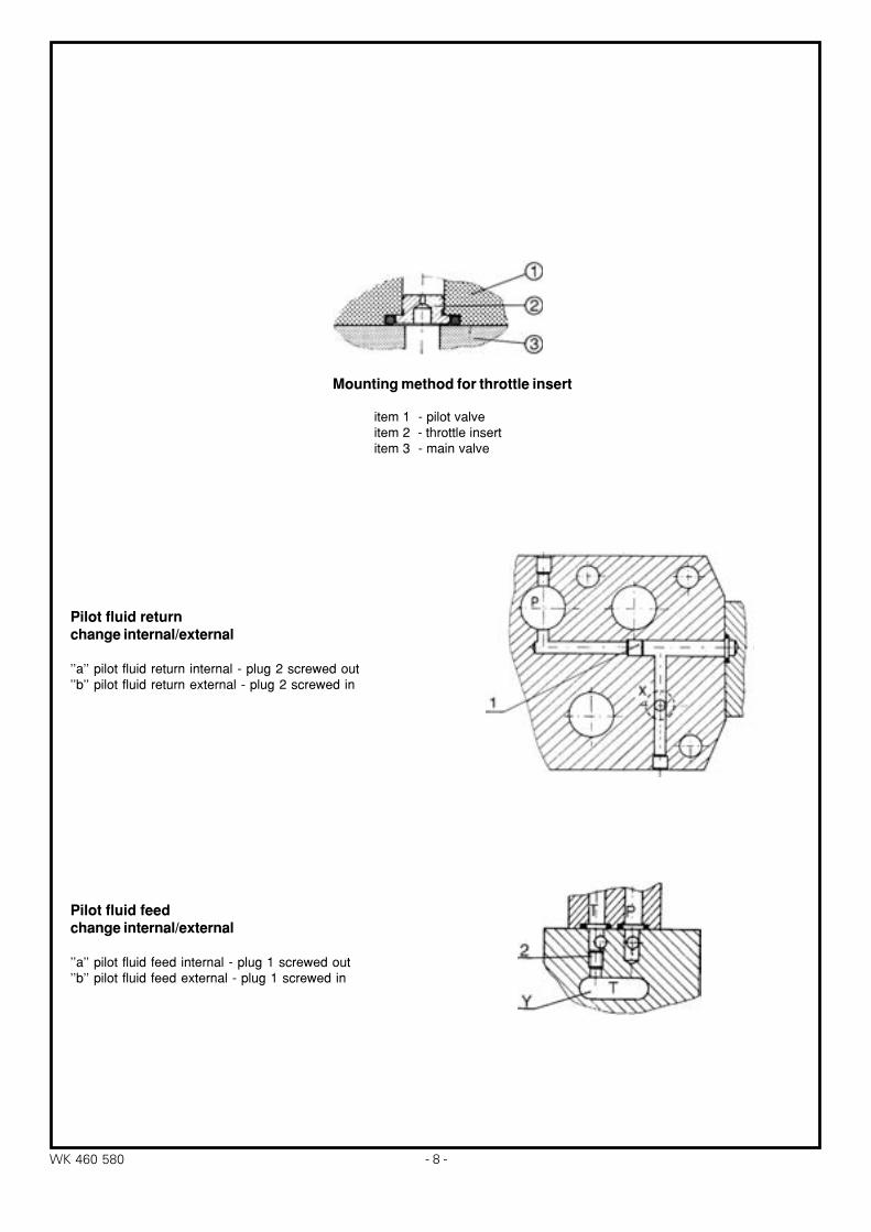
Mounting method for throttle insert
item 1 - pilot valveitem 2 - throttle insertitem 3 - main valve
Pilot fluid returnchange internal/external
''a'' pilot fluid return internal - plug 2 screwed out''b'' pilot fluid return external - plug 2 screwed in
Pilot fluid feedchange internal/external
''a'' pilot fluid feed internal - plug 1 screwed out''b'' pilot fluid feed external - plug 1 screwed in
−9− WK 460 580
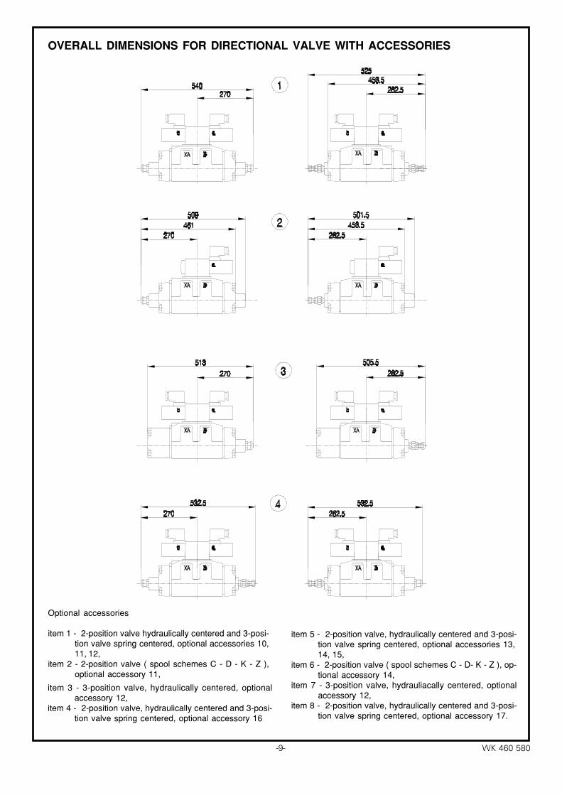
OVERALL DIMENSIONS FOR DIRECTIONAL VALVE WITH ACCESSORIES
Optional accessories
item 1 - 2-position valve hydraulically centered and 3-posi-tion valve spring centered, optional accessories 10,11, 12,
item 2 - 2-position valve ( spool schemes C - D - K - Z ),optional accessory 11,
item 3 - 3-position valve, hydraulically centered, optionalaccessory 12,
item 4 - 2-position valve, hydraulically centered and 3-posi-tion valve spring centered, optional accessory 16
item 5 - 2-position valve, hydraulically centered and 3-posi-tion valve spring centered, optional accessories 13,14, 15,
item 6 - 2-position valve ( spool schemes C - D- K - Z ), op-tional accessory 14,
item 7 - 3-position valve, hydrauliacally centered, optionalaccessory 12,
item 8 - 2-position valve, hydraulically centered and 3-posi-tion valve spring centered, optional accessory 17.
− 10 −WK 460 580
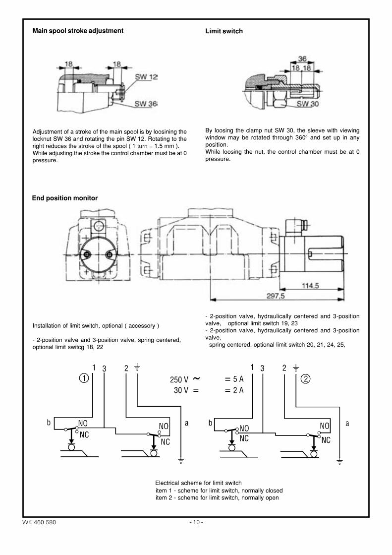
Main spool stroke adjustment
Adjustment of a stroke of the main spool is by loosining thelocknut SW 36 and rotating the pin SW 12. Rotating to theright reduces the stroke of the spool ( 1 turn = 1.5 mm ).While adjusting the stroke the control chamber must be at 0pressure.
Installation of limit switch, optional ( accessory )
- 2-position valve and 3-position valve, spring centered,optional limit switcg 18, 22
End position monitor
- 2-position valve, hydraulically centered and 3-positionvalve, optional limit switch 19, 23- 2-position valve, hydraulically centered and 3-positionvalve, spring centered, optional limit switch 20, 21, 24, 25,
item 1 - scheme for limit switch, normally closeditem 2 - scheme for limit switch, normally open
Electrical scheme for limit switch
By loosing the clamp nut SW 30, the sleeve with viewingwindow may be rotated through 360° and set up in anyposition.While loosing the nut, the control chamber must be at 0pressure.
Limit switch
−11− WK 460 580
0
∆p (M
Pa)
0,8
1,6
1,8
0,6
1,4
0,4
1,2
0,2
1,0
P T→
S
B A→
J;L;M;Q;U;
V;F;H;C;D;K;Z;
720600240120 960840 1100480360Q (dm / min)3
0
∆p (M
Pa)
0,8
1,6
1,8
0,6
1,4
0,4
1,2
0,2
1,0
P A→
A T→
B T→
P B→
B A→
R
E;R;W;
720600240120 960840 1100480360Q (dm / min)3
720600240120 960840 1100480360Q (dm / min)
0
∆p (M
Pa)
0,8
1,6
1,8
0,6
1,4
0,4
1,2
0,2
1,0
P T→
P A→A T→
B T→
P B→G;T;
3
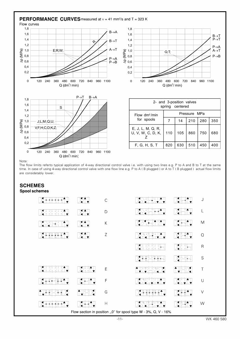
measured at ν = 41 mm2/s and T = 323 KPERFORMANCE CURVESFlow curves
Flow section in position ,,0'' for spool type W - 3%, Q, V - 16%
SCHEMESSpool schemes
2- and 3-position valvesspring centered
Flow dm /minfor spools
Pressure MPa
7 14 210 280 350
E, J, L, M, Q, R,U, V, W, C, D, K,
Z110 105 860 750 680
F, G, H, S, T 820 630 510 450 400
2
Note:The flow limits referto typical application of 4−way directional control valve i.e. with using two lines e.g. P to A and B to T at the sametime. In case of using 4−way directional control valve with one flow line e.g. P to A ( B plugged ) or A to T ( B plugged ) actual flow limitsare considetably lower.
− 12 −WK 460 580
1 2
c
fe
g
d
ba
h
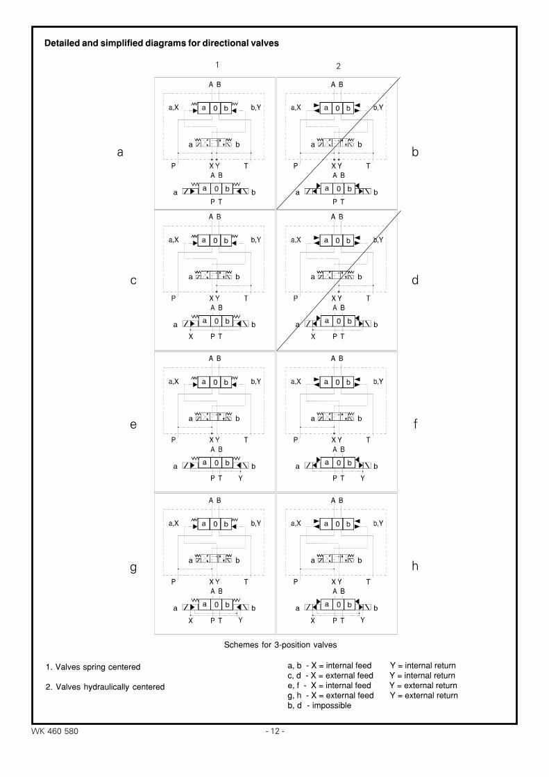
Detailed and simplified diagrams for directional valves
Schemes for 3-position valves
1. Valves spring centered
2. Valves hydraulically centered
a, b - X = internal feed Y = internal returnc, d - X = external feed Y = internal returne, f - X = internal feed Y = external returng, h - X = external feed Y = external returnb, d - impossible
−13− WK 460 580
1
4
3
2
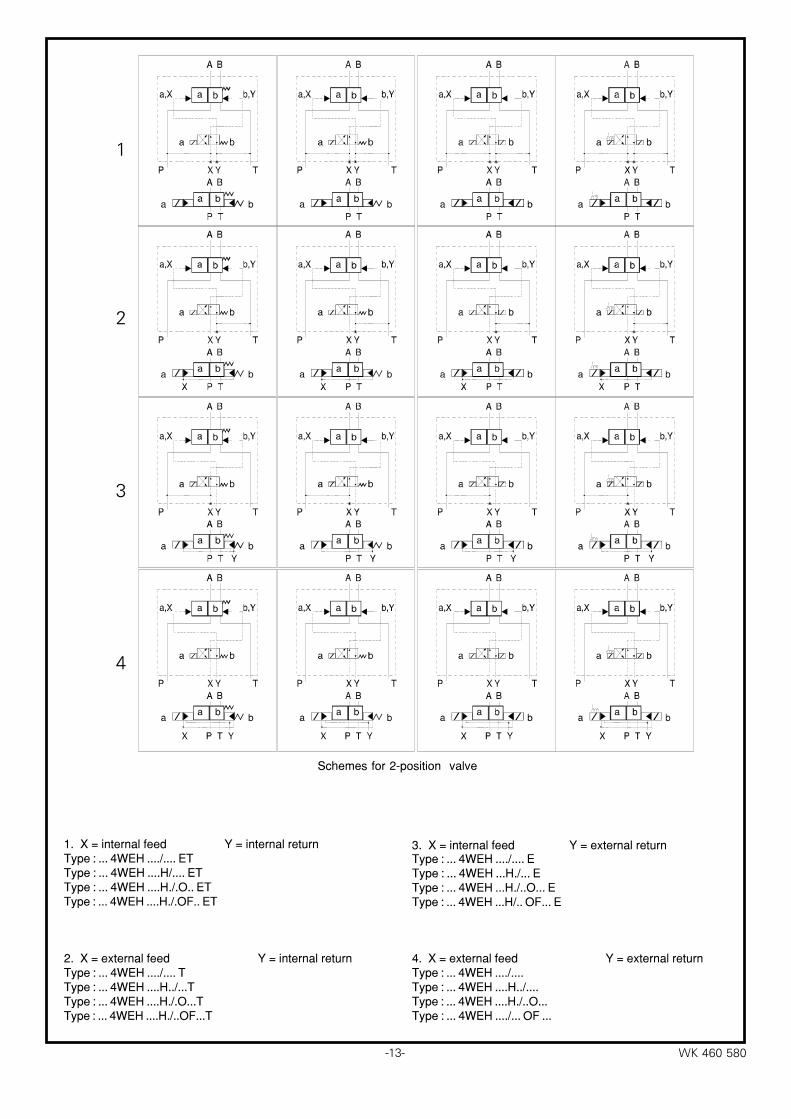
Schemes for 2-position valve
1. X = internal feed Y = internal returnType : ... 4WEH ..../.... ETType : ... 4WEH ....H/.... ETType : ... 4WEH ....H./.O.. ETType : ... 4WEH ....H./.OF.. ET
2. X = external feed Y = internal returnType : ... 4WEH ..../.... TType : ... 4WEH ....H../...TType : ... 4WEH ....H./.O...TType : ... 4WEH ....H./..OF...T
3. X = internal feed Y = external returnType : ... 4WEH ..../.... EType : ... 4WEH ...H./... EType : ... 4WEH ...H./..O... EType : ... 4WEH ...H/.. OF... E
4. X = external feed Y = external returnType : ... 4WEH ..../....Type : ... 4WEH ....H../....Type : ... 4WEH ....H./..O...Type : ... 4WEH ..../... OF ...
− 14 −WK 460 580
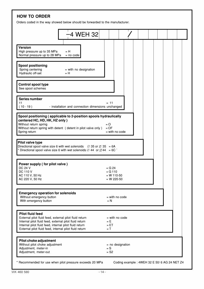
HOW TO ORDER
Version High pressure up to 35 MPa = H Normal pressure up to 28 MPa = no code
Spool positioning Spring centering = with no designation Hydraulic off-set = H
Control spool type See spool schemes
Series number11 = 11( 10 - 19 ) - installation and connection dimensions unchanged
_ 4 WEH 32
Spool positioning ( applicable to 2-position spools hydraulicallycentered HC, HD, HK, HZ only )Without return spring = OWithout return spring with detent ( detent in pilot valve only ) = OFSpring return = with no code
Pilot valve typeDirectional spool valve size 6 with wet solenoids ∅ 35 or 35 = 6A* Directional spool valve size 6 with wet solenoids ∅ 44 or 44 = 6C *
Power supply ( for pilot valve )DC 24 V = G 24DC 110 V = G 110AC 110 V, 50 Hz = W 110-50AC 220 V, 50 Hz = W 220-50
Emergency operation for solenoids Without emergency button = with no code With emergency button = N
Pilot fluid feedExternal pilot fluid feed, external pilot fluid return = with no codeInternal pilot fluid feed, external pilot fluid return = EInternal pilot fluid feed, internal pilot fluid return = ETExternal pilot fluid feed, internal pilot fluid return = T
Pilot choke adjustmentWithout pilot choke adjustment = no designationAdjustment, meter-in = SAdjustment, meter-out = S2
* Recommended for use when pilot pressure exceeds 20 MPa Coding example : 4WEH 32 E 50/ 6 AG 24 NET Z4
Orders coded in the way showed below should be forwarded to the manufacturer.
⁄⁄⁄⁄⁄
−15− WK 460 580
* *
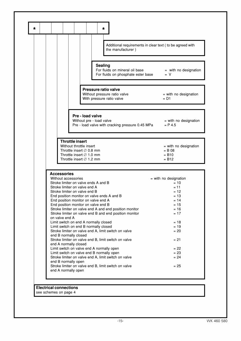
Additional requirements in clear text ( to be agreed withthe manufacturer )
SealingFor fluids on mineral oil base = with no designationFor fluids on phosphate ester base = V
Pressure ratio valveWithout pressure ratio valve = with no designationWith pressure ratio valve = D1
Throttle insertWithout throttle insert = with no designationThrottle insert ∅ 0.8 mm = B 08Throttle insert ∅ 1.0 mm = B10Throttle insert ∅ 1.2 mm = B12
Electrical connectionssee schemes on page 4
Accessories Without accessories = with no designation Stroke limiter on valve ends A and B = 10 Stroke limiter on valve end A = 11 Stroke limiter on valve end B = 12 End position monitor on valve ends A and B = 13 End position monitor on valve end A = 14 End position monitor on valve end B = 15 Stroke limiter on valve end A and end position monitor = 16 Stroke limiter on valve end B and end position monitor = 17 on valve end A Limit switch on end A normally closed = 18 Limit switch on end B normally closed = 19 Stroke limiter on valve end A, limit switch on valve = 20 end B normally closed Stroke limiter on valve end B, limit switch on valve = 21 end A normally closed Limit switch on valve end A normally open = 22 Limit switch on valve end B normally open = 23 Stroke limiter on valve end A, limit switch on valve = 24 end B normally open Stroke limiter on valve end B, limit switch on valve = 25 end A normally open
Pre - load valveWithout pre - load valve = with no designationPre - load valve with cracking pressure 0.45 MPa = P 4.5
−16− WK 460 580
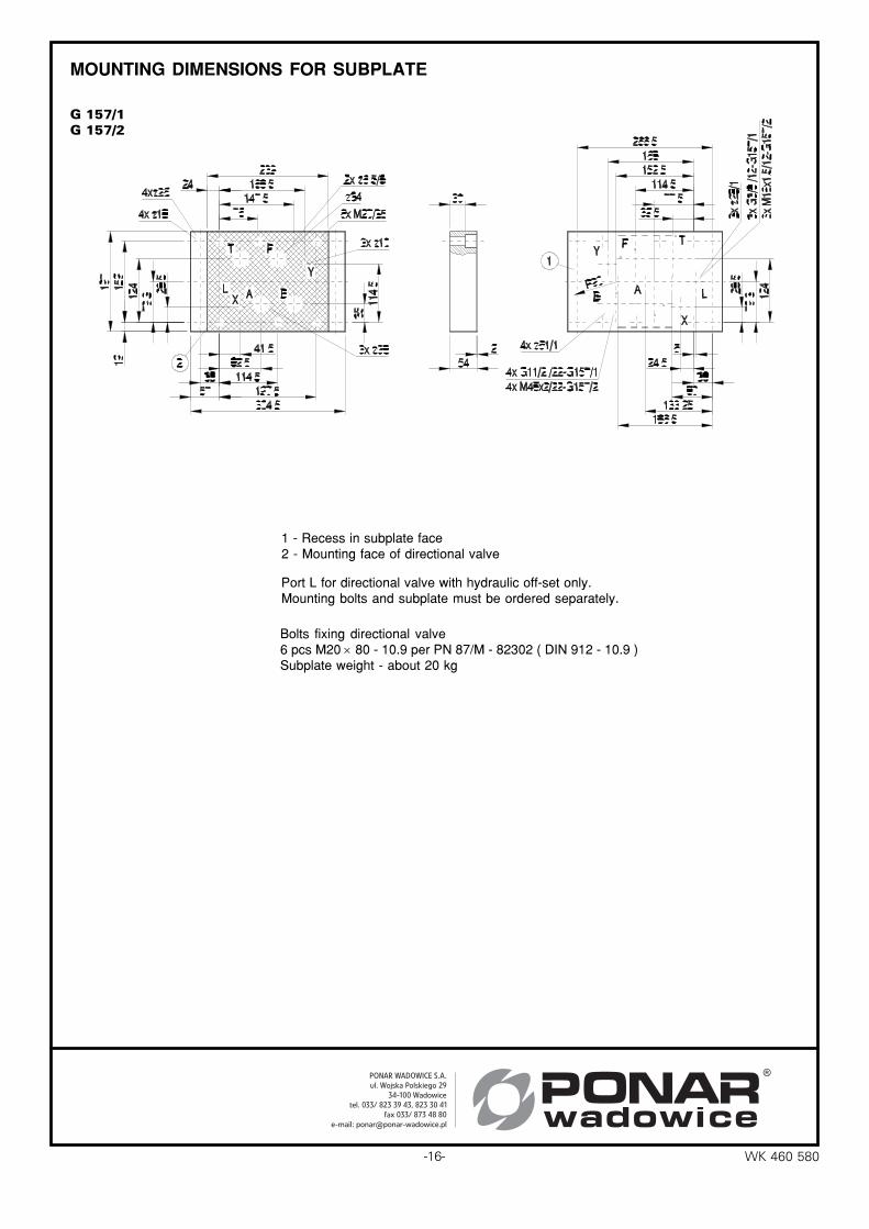
G 157/1G 157/2
MOUNTING DIMENSIONS FOR SUBPLATE
Port L for directional valve with hydraulic off-set only.Mounting bolts and subplate must be ordered separately.
Bolts fixing directional valve6 pcs M20 × 80 - 10.9 per PN 87/M - 82302 ( DIN 912 - 10.9 )Subplate weight - about 20 kg
1 - Recess in subplate face2 - Mounting face of directional valve