Embed Size (px)
Citation preview
INTERNATIONAL JOURNAL OF COMMUNICATION SYSTEMSInt. J. Commun. Syst. 2010; 23:1537–1553Published online 16 March 2010 in Wiley Online Library (wileyonlinelibrary.com). DOI: 10.1002/dac.1123
Direction finding receiver for UWB impulse radio signalin multipath environment
Joni Polili Lie1,∗,†, Boon Poh Ng2 and Chong Meng Samson See3
1Temasek Laboratories@NTU, 9th Storey, BorderX Block, Research Techno Plaza, 50 Nanyang Drive, Singapore2School of Electrical and Electronic Engineering, Nanyang Technological University, Singapore
3DSO National Laboratories, Singapore
SUMMARY
In this paper, we propose a direction finding (DF) receiver for ultra wideband impulse radio (UWB-IR)signal in a realistic multipath environment. The receiver uses an array of antenna, where each antenna isconnected to a proposed propagation-delay estimation structure. The advantage of the proposed structureis that it outputs a trapezoidal signal whose amplitude reflects the propagation delay and thus relaxesthe sampling rate requirement of the analog-to-digital-converter (ADC). The angle-of-arrival (AOA) isestimated from the vector of propagation delays measured with respect to reference antenna. Because theseestimated delays contain outliers, we propose a simple AOA estimation algorithm based on minimumfractional-distance search. Experimental results based on simulation show that the proposed DF receiverachieves better performance compared with the minimum �1- and �2-based (least-squares based) distancesearch. Copyright q 2010 John Wiley & Sons, Ltd.
Received 15 November 2008; Revised 2 September 2009; Accepted 9 January 2010
KEY WORDS: ultra wideband (UWB); impulse radio; direction-of-arrival estimation; fractional distance
1. INTRODUCTION
Ultra wideband impulse radio (UWB-IR) is well known for its short-duration pulse transmission,which can be realized simply by using a pulse-generating circuitry and antenna. Thus, it has agreat potential for low-complexity and low-cost communications system. It is first introduced inradar-related applications [1] and later used for high data rate communications [2–4] as well ashigh precision localization systems [5–8]. The latter requires estimation of location metrics at thereceiving-end.
Time-of-arrival (TOA) is one of the location metrics that can be used for the localization. Itsestimation for UWB-IR has been discussed extensively in the literature. However, the achievable
∗Correspondence to: Joni Polili Lie, Temasek Laboratories@NTU, 9th Storey, BorderX Block, Research TechnoPlaza, 50 Nanyang Drive, Singapore.
†E-mail: [email protected]
Copyright q 2010 John Wiley & Sons, Ltd.

1538 J. P. LIE, B. P. NG AND C. M. S. SEE
resolution requires Nyquist-rate sampling or is limited by the sub-sampling rate used. Further-more, the TOA estimation assumes the transmit time is known at the receiver. In this paper, weconsider angle-of-arrival (AOA) estimation for the UWB-IR system. Unlike TOA estimation, AOAestimation does not need to know the transmit time.
A number of delay-and-sum beamforming techniques have been proposed to estimate the AOAof a UWB-IR signal in a multipath environment [9, 10]. Such techniques require fully or partlythe channel information as aprior knowledge. In [11], a weighted subspace wideband directionfinding (DF) algorithm is proposed to estimate the AOA of the UWB-IR signal. These proposedmethods necessitate the receiver to sample the received signal at Nyquist’s rate. Because of thelarge spectral support of the UWB-IR signal, the receiver needs to sample at very high rates andhandle a huge amount of data. To avoid the need to sample at Nyquist’s rate, the authors in [12]proposed a DF approach using digital channelization receiver architecture. Using the proposedchannelization, the UWB spectrum bins are down-converted into a much lower frequency, henceallowing a low sampling rate ADC to be used.
Unlike previous approaches, our approach is based on detecting the ‘spike’ using an analoglevel-thresholding under the assumption that the noise level of the received signal has been reducedsignificantly by the RF front-end such that the UWB impulse spike is not buried under thenoise‡. To estimate the instant when the ‘spike’ is detected, we propose a simple architecture thatis able to achieve a time resolution finer than the sampling period of the ADC used. By extendingthe proposed single-channel structure to a multi-channel one, the AOA can be estimated fromthe estimated propagation delays of each channel (measured with respect to a reference channel)using a simple minimum-distance search technique [13, 14]. It is worth mentioning that the timeresolution required for the propagation-delay estimation to be used for the AOA estimation issmaller than the pulse duration. Hence, the energy-detection-based approaches [8, 15–17] for thedelay estimation cannot be used because its maximum achievable resolution is of the order of thepulse duration.
The rest of the paper is organized as follows. Section 2 explains the background of UWB-IRtransmission and the modeling of its received signal under a realistic propagation channel. Theproposed structure for propagation-delay estimation, followed with the minimum-distance searchtechnique for AOA estimation are described in Sections 3 and 4, respectively. A validation ofthe proposed techniques based on simulation experiments is given in Section 5. Finally, a shortconclusion is drawn in Section 6.
2. BACKGROUND
UWB-IR system transmits baseband pulses of extremely short duration for communications. Owingto its carrierless transmission, the transmitter may be realized with low-complexity design andmanufactured with low cost. On the receiving end, the non-ideal propagation of the basebandpulses introduces several challenges on the receiver design. Because of multipath propagation, thereplicas of the pulse (propagating from the reflected paths) are also received. In addition, the pulse
‡The authors do not claim that the state-of-the-art RF front-end circuitry is able to achieve the requirements set bythis assumption.
Copyright q 2010 John Wiley & Sons, Ltd. Int. J. Commun. Syst. 2010; 23:1537–1553DOI: 10.1002/dac

DIRECTION FINDING RECEIVER FOR UWB IMPULSE RADIO 1539
shape of the received signal is different from the shape of the transmitted pulse due to the effectsof antenna and propagation.
After the RF front-end, the received signal can be modeled as follows:
r(t)=L∑
l=0alwl(t−�l)+�(t), (1)
where wl is the lth received pulse waveform with unit energy, (al ,�l ) are the attenuationand delay of the lth received pulse and �(t) is the zero-mean additive white gaussian noise(AWGN).
When the single-channel receiving signal model in (1) is extended to a multi-channel signalmodel, each of the received pulse carries a unique spatial information captured using an antennaarray. Let {�l} denote the AOA of the lth pulse, measured with respect to the array axis. These AOAdetermine the additional propagation delay, with respect to the propagation delay at the referencechannel, and at the receiving antenna array. To formulate the propagation delay, consider the firstchannel to be the reference and let rn be the position of the nth antenna measured with respect tothe position of the reference antenna. Given the propagation speed c, the propagation delay of thenth channel �l,n can be expressed as follows:
�l,n = rTnklc
, (2)
where kl =[sin(�l)cos(�l),sin(�l)sin(�l),cos(�l)]T, �l and �l are the elevation and azimuth angleof the lth pulse, respectively. The superscript T denotes the transpose operation. Thus, the receivedsignal at the nth channel is given by
rn(t)=L∑
l=0alwl(t−�l −�l,n)+�(t). (3)
Figure 1 shows an example of the received signal at the reference (0th), 3rd and 6th antenna.The objective of this paper is to design a multi-channel UWB-IR receiving system that estimates
the AOA of the received pulse propagating from the direct path. The estimate can then be used asthe location metrics for the UWB-IR localization system.
3. PROPAGATION DELAY ESTIMATION
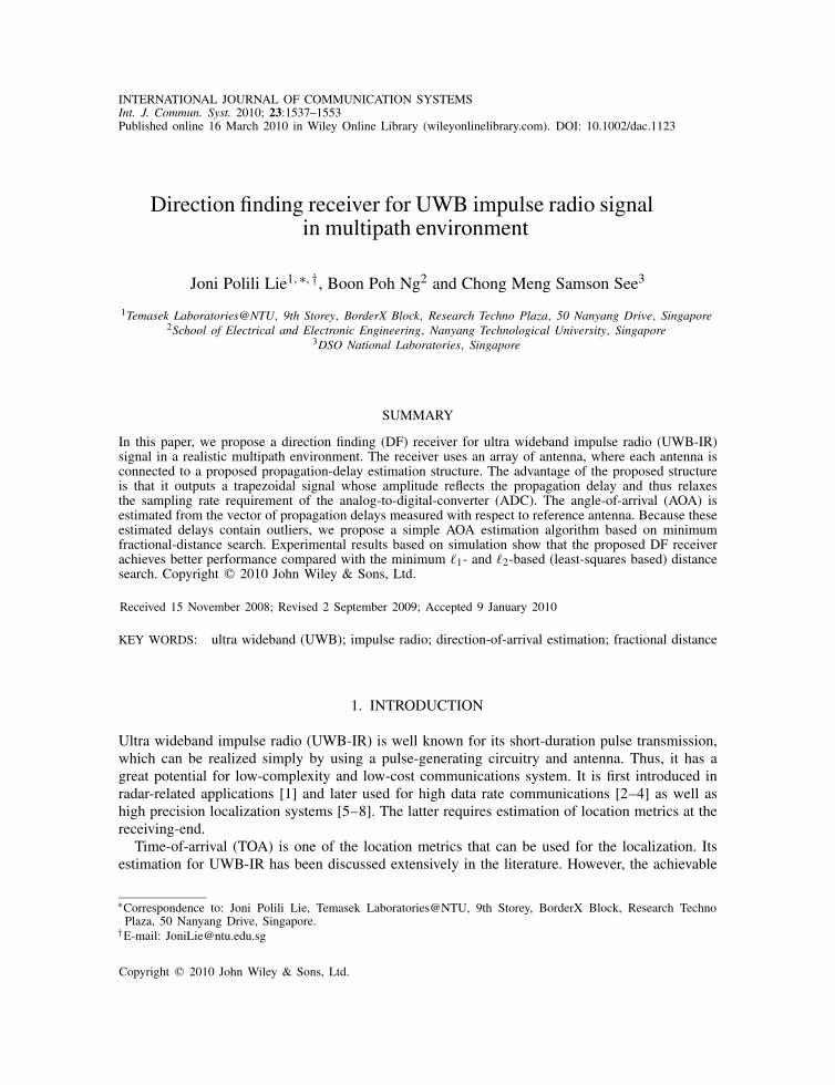
This section describes the proposed structure for estimating the propagation delay of the receivedpulse from the direct path, as shown in Figure 2. Because the direct path is the shortest pathpossible for the transmitted pulse to reach the receiver, the received pulse from the direct path willarrive first at the antenna. It is important to mention that because the emission power for UWBtransmission is limited, it is very likely that the UWB impulse is buried under the noise floorwhen received at the antenna. In our model, we assume that a signal pre-conditioning step at theRF front-end has been implemented in order to reduce the noise floor significantly such that theUWB impulse ‘spike’ level is above the noise floor. From the difference between the noise floorand the ‘spike’ of the received pulse, a simple comparator can be utilized to indicate the pulse.The challenge here is how to measure accurately the instant when the comparator switches itsoutput. We utilize a simple structure to estimate the propagation delay from the difference between
Copyright q 2010 John Wiley & Sons, Ltd. Int. J. Commun. Syst. 2010; 23:1537–1553DOI: 10.1002/dac
1540 J. P. LIE, B. P. NG AND C. M. S. SEE
0 0.5 1 1.5 2 2.5 3 3.5
0
0.5
time [sec]
ampl
itude
[uV
]
0 0.5 1 1.5 2 2.5 3 3.5
0
0.5
time [sec]
ampl
itude
[uV
]
0 0.5 1 1.5 2 2.5 3 3.5
0
0.5
time [sec]
ampl
itude
[uV
]
(a)
(c)
(b)
Figure 1. A realization of received UWB-IR signal at: (a) 0th; (b) 3rd; and(c) 6th antenna that forms the array.
Figure 2. Proposed structure for estimating propagation delay of the received pulse from the direct path.The UWB impulse signal before comparator is assumed to have been pre-conditioned such that the noise
level is significantly reduced and the UWB impulse is no longer buried under the noise.
comparator switching instances of two channel, where the latter is the reference. It is worth notingthat the proposed structure utilizes low-rate ADC, yet achieves time resolution finer than the ADCrate.
As shown in Figure 2, the proposed structure consists of a comparator, latch circuit, integratorand ADC. Shown in Figure 2 are the waveforms at points designated by labels (a–d) for a typical
Copyright q 2010 John Wiley & Sons, Ltd. Int. J. Commun. Syst. 2010; 23:1537–1553DOI: 10.1002/dac

DIRECTION FINDING RECEIVER FOR UWB IMPULSE RADIO 1541
0 0.1 0.2 0.3 0.4 0.5 0.6 0.7 0.8 0.9 1
0
0.2
0.4
time [sec]
ampl
itude
[uV
]
0 0.1 0.2 0.3 0.4 0.5 0.6 0.7 0.8 0.9 1
0
0.5
1
time [sec]
ampl
itude
[vol
t]
0 0.1 0.2 0.3 0.4 0.5 0.6 0.7 0.8 0.9 1
0
0.5
1
time [sec]
ampl
itude
[vol
t]
0 0.1 0.2 0.3 0.4 0.5 0.6 0.7 0.8 0.9 1
0
2
4
6
time [sec]
ampl
itude
[vol
t]
(b)
(c)
(d)
(a)
Figure 3. Illustration of the signals at various stages of the proposed structure in Figure 2.
received UWB-IR signal. Consider the threshold is set at the level above the noise floor.§ At theinstant when (a) is higher than the threshold, the comparator will switch its output and generate (b).Upon detecting the switching event, the latch circuit will produce a rectangular wave (c).The pulse duration of (c) will be determined by the latch duration and should be set at a muchlonger duration in order to ignore the switching event due to the reflected-path pulses. Therectangular wave is then integrated to produce the waveform (d) (Figure 3).
Let �n denote the first instant when the waveform (a) is higher than the threshold and is taken asthe estimated propagation delay. The rectangular wave (c) produced by the latch can be expressedas follows:
(c) :H(t− �n)−H(t− �n−Tlatch), (4)
where H(t) denotes the Heaviside step function and Tlatch is the latch duration. Since it is wellknown that the integration of a Heaviside step function produces a ramp function, R(t), therefore,
§This setting has to be achieved during calibration of the structure.
Copyright q 2010 John Wiley & Sons, Ltd. Int. J. Commun. Syst. 2010; 23:1537–1553DOI: 10.1002/dac

1542 J. P. LIE, B. P. NG AND C. M. S. SEE
Figure 4. Proposed array structure constructed from extending the single-channelstructure in Figure 2 to the multi-channel.
we can express the waveform (d) as follows:
(d) : R(t− �n)−R(t− �n−Tlatch)
=
⎧⎪⎨⎪⎩
t− �n, �n�t��n+Tlatch,
−(t− �n−2Tlatch), �n+Tlatch�t��n+2Tlatch,
0 otherwise.
(5)
The next procedure for estimating the propagation delay is as follows. Consider a N -channelantenna array and each channel implements the proposed structure in Figure 2. Assume the firstchannel to be the reference, the propagation delay is reflected at the amplitude of the waveformproduced by the summer, labeled as (c) in Figure 5.
Let �0 denote the estimated propagation delay at the reference. The waveform at Figure 5(c)can be expressed as follows:
[R(t− �n)−R(t− �n−Tlatch)]−[R(t− �0)−R(t− �0−Tlatch)]. (6)
Given that the estimated propagation delays satisfy the following inequality �0��n <Tlatch, thewaveform at Figure 5(c) can be simplified as follows:
⎧⎪⎪⎪⎪⎪⎪⎪⎪⎪⎪⎨⎪⎪⎪⎪⎪⎪⎪⎪⎪⎪⎩
t− �0, �0�t��n,
�n− �0, �n�t��0+Tlatch,
−(2t− �0− �n−Tlatch), �0+Tlatch�t��n+Tlatch,
�0− �n, �n+Tlatch�t��0+2Tlatch,
−(t− �n−2Tlatch), �0+2Tlatch�t��n+2Tlatch,
0 otherwise.
(7)
For better explanation, the reader can refer to Figure 6. On the basis of the above formulation,the inter-element delay estimate is reflected at the amplitude of the waveform at Figure 5(c) when�0�t��0+Tlatch.
This waveform is then sampled by ADC and its amplitude is the inter-element delay estimate(Figure 4). The ADC considered is based on the modification of direct-conversion (flash) ADC,
Copyright q 2010 John Wiley & Sons, Ltd. Int. J. Commun. Syst. 2010; 23:1537–1553DOI: 10.1002/dac

DIRECTION FINDING RECEIVER FOR UWB IMPULSE RADIO 1543
0 0.5 1 1.5
0
2
4
6
time [sec]
ampl
itude
[vol
t]
(a)
0 0.5 1 1.5
0
2
4
6
time [sec]
ampl
itude
[vol
t]
0 0.5 1 1.5
0
1
time [sec]
ampl
itude
[vol
t]
(b)
(c)
the amplitude level indicates
the delay shift between
the above two waveforms
Figure 5. Illustration of the procedure to extract the inter-element delay from the outputs of the twosingle-channel structures. The figures are labeled according to the labels shown in Figure 4.
Figure 6. The illustration used to derive the equation representation of Figure 5(c).
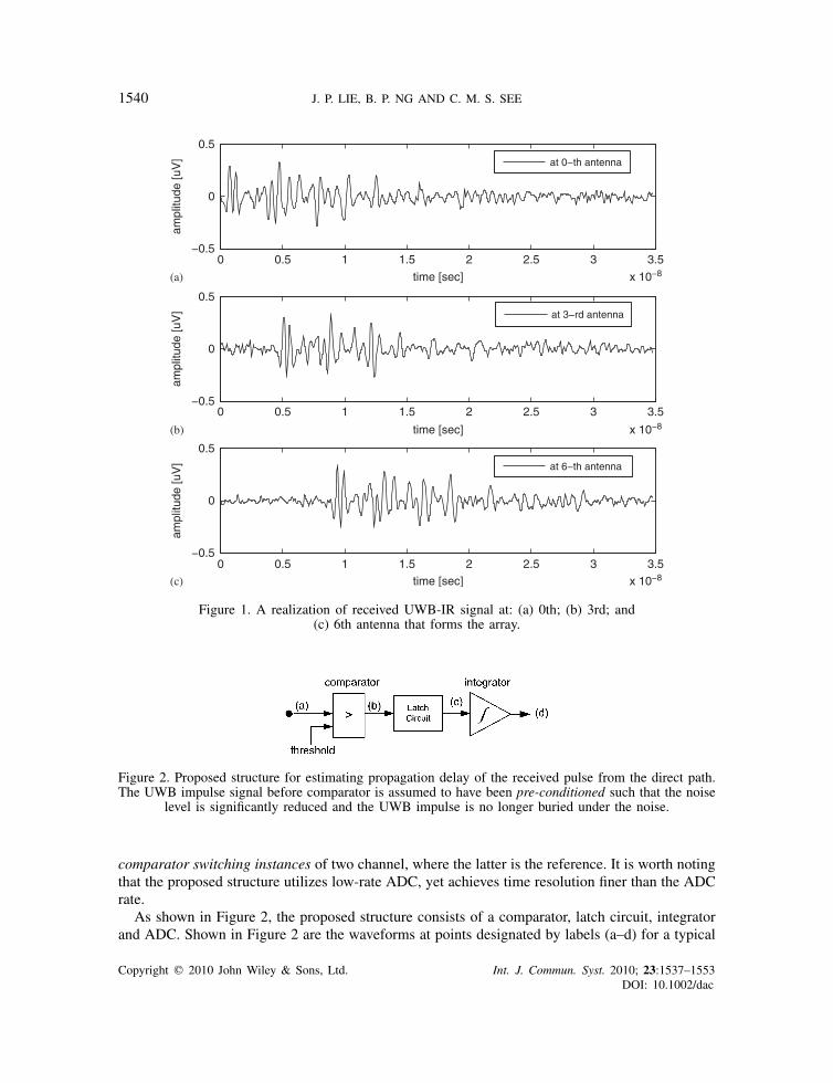
as shown in Figure 7. Notice that the resistor values for setting the threshold for the comparatorsare adjusted based on the required angular resolution. For example, to achieve 1◦ resolution, 180comparators are required and their thresholds are set such that each output corresponds to a uniqueAOA. These thresholds are given by
vthres(�scan)= 1
crTnko(�scan), (8)
Copyright q 2010 John Wiley & Sons, Ltd. Int. J. Commun. Syst. 2010; 23:1537–1553DOI: 10.1002/dac
1544 J. P. LIE, B. P. NG AND C. M. S. SEE
Figure 7. Proposed direct-conversion ADC model to be implemented as partof the structure proposed in Figure 4.
where �scan={0◦,1◦, . . . ,180◦} for 1◦-resolution DF. To realize the 180 comparators, the resolutionfor the proposed ADC is B=8 bits.¶
The overall proposed structure is essentially based on the idea that exploits the different prop-agation delays at each antenna in order to lower the required ADC speed. A similar idea hasalso been used in the time-interleaved ADC (TI-ADC) design since 1980s [18, 19]. As the nameimplies, the idea is to split the analog input into M parallel channels so that the sampling ratecan be increased by M factor. Each parallel channel only needs to use 1/M of the required ADCrate. Unlike the TI-ADC structure, the proposed structure only needs to resolve the full bandwidthof the waveform at Figure 4(c) instead of the initial bandwidth of the UWB signal. Moreover,the proposed structure requires only single ADC, whereas the TI-ADC needs M ADC. This ispossible because the proposed structure is only interested in the time value, whereas the TI-ADCproduces both the amplitude and time value.
4. AOA ESTIMATION
Ideally, given the N−1 estimates of the inter-element propagation delay, its relationship with theAOA can be expressed as follows [13, 14]:
so= 1
cRko+e, (9)
where so=[�0,1, �0,2, . . . , �0,N−1]T, R=[rT1 ,rT2 , . . . ,rTN−1]T and e is the error vector. Notice thatthe matrix equation in (9) is a linear system of the equation. Thus, the estimation can be realized by
¶B-bit ADC is able to detect 2B signal levels.
Copyright q 2010 John Wiley & Sons, Ltd. Int. J. Commun. Syst. 2010; 23:1537–1553DOI: 10.1002/dac

DIRECTION FINDING RECEIVER FOR UWB IMPULSE RADIO 1545
searching for the AOA that minimizes the square-error terms known as least squares (LS) solution.When the error vector is normally distributed random variable, the asymptotic performance of theLS solution has been shown to achieve the Cramer Rao bound (see [20] for the derivation andproof).
Unfortunately, the results from the simulation experiments (as detailed in Section 5) show thatthe error has a heavy-tailed distribution rather than a normal distribution. If the LS solution is usedfor the estimation, it is not a robust one. To overcome this, instead of minimizing the Euclideandistances or LS errors, the estimator is reformulated as minimizing the fractional distances [21, 22]:
(�o, �o)=argmin�,�
‖e(�,�)‖p, (10)
where ‖·‖p denote �p-norm operation and 0< p<1.In the next section, we validate the proposed AOA estimator using the results obtained from
the simulation experiments.
5. SIMULATION EXPERIMENTS
5.1. Experiment setup
We set up a MATLAB simulation to validate the proposed DF receiver. Consider a 10-elementUWB antenna array of 5cm inter-element spacing. The array is positioned in an indoor officeenvironment, and is receiving the signal from UWB-IR transmitter located 10m away from it.Measured with respect to the array axis, the transmitter is 30◦ away from the array. The array andthe transmitter are assumed to be at the same height.
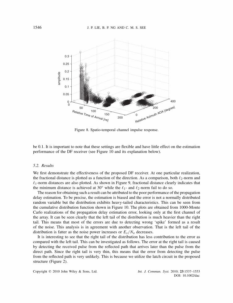
Since it is an indoor environment, the propagation channel is a dense multipath channel.In this experiment, we use the model provided by Foerster [23] to realize the multipath propagation.One of the realization results is detailed as follows. As many as 305 unique propagation paths(including one direct path) are generated, each with its unique attenuation and delay. As for theirspatial information, we use the model reported in [24]. Each propagation path is grouped underdifferent clusters and its AOA has Laplacian distribution (with the standard deviation set at 25.5◦)and centered around its cluster’s AOA. The cluster’s AOA is uniformly distributed. As a whole,each propagation path is uniquely defined by three parameters attenuation, delay and AOA. Therealization of the multipath channel is represented as impulse response and is shown in Figure 8.
Taking into account antenna’s effect and other non-idealities during propagation, the pulsewaveform at the receiver is assumed to be a Gaussian second derivative pulse [25]. The pulsewidth is set such that the spectrum of the pulse spans over 4GHz bandwidth. At each channelof the array, the signal-to-noise ratio (SNR) is assumed to be equal and can be defined asSNR=Es/No=(
∑Ll=0 a
2l )/No, where No denotes the noise power spectral density (W/Hz) (PSD).
Unless otherwise stated, the SNR is set at 21 dB.As shown in Figure 4, The DF receiver is constructed from N =10 sets of the proposed
delay estimation structure, together with ADC that samples the delay estimates reflected fromthe amplitude level and AOA estimation algorithm. The delay estimation structure is configuredaccording to the following description comparator’s threshold is set above the noise floor at 0.3V(obtained after calibrating the structure), the latch duration is 50 ns and the ADC rate is 20MHz.As for the AOA algorithm, the parameter p that defines the fractional-distance calculation is set to
Copyright q 2010 John Wiley & Sons, Ltd. Int. J. Commun. Syst. 2010; 23:1537–1553DOI: 10.1002/dac
1546 J. P. LIE, B. P. NG AND C. M. S. SEE
0
200
4000
50100
150200
0
0.05
0.1
0.15
0.2
0.25
0.3
Relative Azimuth AOA [degree]Relative Time of Arrival [ns]
ampl
itude
Figure 8. Spatio-temporal channel impulse response.
be 0.1. It is important to note that these settings are flexible and have little effect on the estimationperformance of the DF receiver (see Figure 10 and its explanation below).
5.2. Results
We first demonstrate the effectiveness of the proposed DF receiver. At one particular realization,the fractional distance is plotted as a function of the direction. As a comparison, both �2-norm and�1-norm distances are also plotted. As shown in Figure 9, fractional distance clearly indicates thatthe minimum distance is achieved at 30◦ while the �1- and �2-norm fail to do so.
The reason for obtaining such a result can be attributed to the poor performance of the propagationdelay estimation. To be precise, the estimation is biased and the error is not a normally distributedrandom variable but the distribution exhibits heavy-tailed characteristics. This can be seen fromthe cumulative distribution function shown in Figure 10. The plots are obtained from 1000-MonteCarlo realizations of the propagation delay estimation error, looking only at the first channel ofthe array. It can be seen clearly that the left tail of the distribution is much heavier than the righttail. This means that most of the errors are due to detecting wrong ‘spike’ formed as a resultof the noise. This analysis is in agreement with another observation. That is the left tail of thedistribution is fatter as the noise power increases or Es/No decreases.
It is interesting to see that the right tail of the distribution has less contribution to the error ascompared with the left tail. This can be investigated as follows. The error at the right tail is causedby detecting the received pulse from the reflected path that arrives later than the pulse from thedirect path. Since the right tail is very thin, this means that the error from detecting the pulsefrom the reflected path is very unlikely. This is because we utilize the latch circuit in the proposedstructure (Figure 2).
Copyright q 2010 John Wiley & Sons, Ltd. Int. J. Commun. Syst. 2010; 23:1537–1553DOI: 10.1002/dac

DIRECTION FINDING RECEIVER FOR UWB IMPULSE RADIO 1547
0 20 40 60 80 100 120 140 160 180
100
scanning direction [degree]
norm
aliz
ed c
ost f
unct
ion
p=0.1p=1p=2true DOAtrue DOA
Figure 9. Fractional-distance plot as a function of the AOA in comparisonwith �1- and �2-norm distance plots.
0 0.2 0.4 0.60
0.1
0.2
0.3
0.4
0.5
0.6
0.7
0.8
0.9
1
F(x
): E
mpi
rical
CD
F
Es/No=25dBEs/No=23dBEs/No=21dB
Figure 10. Cumulative distribution function plots of the delay estimation error at channel 1 of the array,obtained from 1000-Monte Carlo realizations.
In the next experiment, we investigate the effect of the latch duration setting (denoted as Tlatch)on the effectiveness of the proposed structure. To do this, we introduce a probabilistic measureto quantify a false detection. We record the likeliness of detecting the pulse from any of thereflected paths, given a range of Tlatch. We denote this probability as Pmp. Out of 1000-MonteCarlo realizations, Pmp obtained can be as low as 10−5 and as high as 0.05 for either line-of-sight
Copyright q 2010 John Wiley & Sons, Ltd. Int. J. Commun. Syst. 2010; 23:1537–1553DOI: 10.1002/dac

1548 J. P. LIE, B. P. NG AND C. M. S. SEE
10 20 30 40 50 60
Tlatch [ns]
Pm
p
LOS
NLOS
Figure 11. Likelihood of detecting the pulse from any reflected paths given the propagation channel isline-of-sight (LOS) or non-line-of-sight (NLOS).
(LOS) or non-line-of-sight (NLOS) propagation channel. A much lower Pmp can be obtained whenTlatch is set to be longer than 60 ns. Figure 11 shows the results in detail.
It has been shown earlier in Figure 9 that the proposed fractional-distance-based AOA estimationis still reliable even when the propagation delay estimates are not reliable due to the heavy-tailedresults. Here, we extend the experiment to include more estimation results in order to providean objective analysis. We gather the estimation results from 1000-Monte Carlo realizations andcalculate its root mean square error (RMSE) value. The results are plotted as a function ofEs/No in Figure 12. From the plots, it can be shown that the proposed fractional-distance-basedAOA estimator achieves better performance as compared with the �1- and �2-based estimators.Furthermore, the choice of the parameter p has little effect on the performance.
Next, we investigate the trade-off between the complexity from increasing the number of antennasN and the estimation performance. In particular, we calculate the RMSE values obtained fordifferent values of N considered with the fractional-distance parameter p=0.5. The simulationparameters considered in the previous simulations are not changed, except the number of antennas.This experiment is repeated for different values of Es/No and the RMSE results are plotted inFigure 13. These results imply that there is a very little trade-off between the complexity fromincreasing the number of antennas N and the performance. This means that the proposed solutiondoes not require large N , and can thus be considered as low-complexity solution.
5.3. Performance comparison against other methods
In [11], the method weighted coherent signal-subspace method (WCSM) is proposed to estimatethe AOA of a UWB-IR signal. It is based on focusing matrix approach proposed earlier in [26].Instead of only using the focusing matrix, it uses a weighted version of the focusing matrix.The weight is designed based on the UWB signal PSD. In summary, the WCSM method can be
Copyright q 2010 John Wiley & Sons, Ltd. Int. J. Commun. Syst. 2010; 23:1537–1553DOI: 10.1002/dac

DIRECTION FINDING RECEIVER FOR UWB IMPULSE RADIO 1549
19 20 21 22 23 24 25 26 27 28 290
5
10
15
20
25
30
Es/No [dB]
RM
SE
[deg
ree]
p=0.1p=0.5p=0.9p=1p=2
Figure 12. Root mean square error (RMSE) performance of the DF receiver as a function of Es/No.
19 20 21 22 23 24 25 26 27 28 290
5
10
15
20
25
30
Es/No [dB]
RM
SE
[deg
ree]
N=4N=6N=8N=10
Figure 13. Root mean square error (RMSE) performance of the DF receiver as a function of Es/No.
formulated as follows. The discrete Fourier series representation of the received signal at the array(see Equation (3)) can be expressed as follows:
Rn(�k)=L∑
l=1alWl(�k)exp(−i�k�l,n)+N (�k), (11)
Copyright q 2010 John Wiley & Sons, Ltd. Int. J. Commun. Syst. 2010; 23:1537–1553DOI: 10.1002/dac

1550 J. P. LIE, B. P. NG AND C. M. S. SEE
where i is the imaginary unit (i=√−1), Wl(�k) and N (�k) are the Fourier series representation
of wl(t−�l) and �(t), respectively. For N received signals, the above equation can be expressedin a matrix form
r=A f (�)w+n, (12)
where the matrices are defined as follows:
r= [R1 . . . RN ]T, (13)
A f (�) = [a(�1) . . . a(�L)], (14)
a(�l) = [exp(−i�k�l,0) . . . exp(−i�k�l,N−1)]T, (15)
w= [a1W1 . . . aLWL ]T, (16)
n= [N1 . . . NN ]T, (17)
where [·]T denotes the matrix transpose operation. Notice that the notation �k is temporarilyremoved for brevity. Assuming no correlation between the signal and the noise, the covariancematrix is expressed as follows:
Pr =E[rrH ]=A f (�)PwAHf (�)+Pn, (18)
where Pn =E[nnH ] and Pw =E[wwH ] are the covariance matrices of n and w, respectively.E[·] symbolizes the expectation operation and the superscript H represents the Hermitian matrixoperation. The size of the matrices are N×N and L×L , respectively.
The key idea of the approach is to design a focusing matrix T(�k) such that
A f (�o,�)=T(�k)A f (�k,�) ∀k. (19)
With these matrices, we can, therefore, combine the spatial information spread across the differentfrequency bins. The modification proposed by WCSM as compared with the original focusingmatrix is that the linear combination is weighted by the UWB signal PSD. Thus, the covariancematrix after combining is
P=∑kPs(�k)T(�k)Pr (�k)TH (�k), (20)
where Ps(�k) is the UWB signal PSD. By eigen-decomposing P, it is possible to form a signalsubspace from L eigenvectors corresponding to L largest eigenvalues. Hence, subspace-searchtechnique, such as MUSIC can be applied to estimate the AOA.
In multipath propagation environment, the focusing matrix approach tries to estimate all theAOAs of the multipath. Because the approach is only capable of estimating the AOA from N−1sources, it requires enormous amounts of antennas to estimate all the multipath AOAs. For instance,we need 306 antennas to resolve all the AOA from 305-multipath signal from the realization ofthe multipath channel discussed in Section 5.1.
For comparison purpose, we only use 10-element UWB antenna array to implement the WCSMapproach. The other configurations are described as follows. We assume that higher-than-Nyquistrate sampling of the received at the array is available for processing. To be exact, the discrete repre-sentation of the received signal sample at 100GHz rate is used to obtain 32-discrete Fourier series
Copyright q 2010 John Wiley & Sons, Ltd. Int. J. Commun. Syst. 2010; 23:1537–1553DOI: 10.1002/dac

DIRECTION FINDING RECEIVER FOR UWB IMPULSE RADIO 1551
19 20 21 22 23 24 25 26 27 28 290
10
20
30
40
50
60
70
80
90
100
Es/No [dB]
RM
SE
[deg
ree]
Figure 14. Root mean square error (RMSE) performance of the DF receiver as a function of Es/No.
of Rn(�k) centered around the frequency corresponding to the largest PSD. The 32-covariancematrices (estimated from 100 observations of the received signal) are then combined to formP according to (15) assuming that the UWB signal PSD is known.
Besides the WCSM method, we also compare the performance against the proposed channelizermethod reported in [12]. The method is formulated based on the multipath-free assumption.Therefore, it is expected to perform poorly in a multipath propagation environment. For ourcomparison, we consider 30 spectrum bins to be extracted in order to form the cost func-tion (see Equation (4) in [12]). Unlike the WCSM approach, this approach does not requirethe focused covariance matrix. Therefore, the estimation can be achieved with only singleobservation.
Figure 14 shows the RMSE plot for the WCSM method, the channelizer DF in comparison withthe proposed method. As both the WCSM and channelizer DF methods are formulated under themultipath-free assumption, the degradation in the performance is very obvious. On the contrary, theproposed method is derived based on multipath propagation assumption. As a result, the proposedmethod outperforms the other two methods.
6. CONCLUSIONS
The contributions presented in this paper are two-fold. First is the proposed structure for estimatingthe propagation delay using low-rate ADC, but achieves a time resolution finer than its samplinginterval. Another is that by extending this structure from single channel to multiple channel, wehave demonstrated that a reliable AOA can be estimated from the estimated propagation delaysusing a simple minimum fractional-distance search technique. These two methods have been usedto form the proposed DF receiver.
Copyright q 2010 John Wiley & Sons, Ltd. Int. J. Commun. Syst. 2010; 23:1537–1553DOI: 10.1002/dac

1552 J. P. LIE, B. P. NG AND C. M. S. SEE
REFERENCES
1. Taylor JD. Introduction to Ultra-Wideband Radar Systems. CRC Press: Boca Raton, FL, 1995.2. Win MZ, Scholtz RA. Impulse radio: How it works. IEEE Communications Letters 1998; 2(2):36–38.3. Win MZ, Scholtz RA. Ultra-wide bandwidth time-hopping spread-spectrum impulse radio for wireless multiple-
access communications. IEEE Transactions on Communications 2000; 48(4):679–691.4. Qiu RC, Liu H, Shen X. Ultra-wideband for multiple access communications. IEEE Communications Magazine
2005; 43(2):80–87.5. Ingram SJ, Harmer D, Quinlan M. Ultra wide band indoor positioning systems and their use in emergencies.
Proceedings of IEEE Position Location and Navigation Symposium 2004 (PLANS 2004), Monterey, CA, April2004; 706–715.
6. Mazzucco C, Spagnolini U, Mulas G. A ranging technique for UWB indoor channel based on power delayprofile analysis. Proceedings of IEEE Vehicular Technology Conference (VTC 2004 Spring), vol. 5, May 2004;2595–2599. DOI: 10.1109/VETECS.2004.1391391.
7. Gezici S, Tian Z, Giannakis GB, Kobayashi H, Molisch AF, Poor HV, Sahinoglu Z. Localization via ultra-wideband radios: A look at positioning aspects of future sensor networks. IEEE Signal Processing Magazine2005; 22(4):70–84.
8. Denis B, Pierrot JB, Abou-Rjeily C. Joint distributed synchronization and positioning in UWB Ad Hoc networksusing TOA. IEEE Transactions on Microwave Theory and Techniques 2006; 54(4):1896–1910.
9. Ries S, Kaiser T. Ultra wideband impulse beamforming: It is a different world. Signal Processing 2006;86(9):2198–2207.
10. Hussain MGM. Principles of space-time array processing for ultrawide-band impulse radar and radiocommunications. IEEE Transactions on Vehicular Technology 2002; 51(3):393–403.
11. Keshavarz H. Weighted signal-subspace direction-finding of ultra-wideband sources. 2005 IEEE InternationalConference on Wireless and Mobile Computing, Networking and Communications (WiMob’2005), vol. 1, 24August 2005; 23–29. DOI: 10.1109/WIMOB.2005.1512811.
12. Lie JP, See CM, Ng BP. Ultra wideband direction finding using digital channelization receiver architecture. IEEECommunications Letters 2006; 10(2):85–87.
13. Berdugo B, Doron MA, Rosenhouse J, Azhari H. On direction finding of an emitting source from time delays.Journal of Acoustical Society of America 1999; 105(6):3355–3363.
14. Berdugo B, Rosenhouse J, Azhari H. Speakers’ direction finding using estimated time delays in the frequencydomain. Signal Processing 2002; 82(1):19–30.
15. Cassioli D, Win MZ, Vatalaro F, Molisch AF. Performance of low-complexity rake reception in arealistic UWB channel. IEEE International Conference on Communications, vol. 2, 2002; 763–767. DOI:10.1109/ICC.2002.996958.
16. Guvenc I, Sahinoglu Z, Orlik PV. TOA estimation for IR-UWB systems with different transceiver types. IEEETransactions on Microwave Theory and Techniques 2006; 54(4):1876–1886.
17. Gezici S, Sahinoglu Z, Molisch AF, Kobayashi H, Poor HV. Two-step time of arrival estimation for pulse-basedultra-wideband systems. EURASIP Journal on Advances in Signal Processing 2008. DOI: 10.1155/2008/529134.Article ID 529134: 11 pages.
18. Black WC, Hodges DA. Time interleaved converter arrays. IEEE Journal of Solid-State Circuits 1980; 15(6):1022–1029.
19. Brown Jr J. Multi-channel sampling of low-pass signals. IEEE Transactions on Circuits and Systems 1981;28(2):101–106.
20. Kay SM. Fundamentals of Statistical Signal Processing: Estimation Theory. Prentice-Hall: New Jersey, 1993.21. Doherty K, Adams R, Davey N. Non-euclidean norms and data normalisation. 12th European Symposium on
Artificial Neural Networks, Verleysen M (ed.), Bruges, Belgium, April 2004; 181–186.22. Francois D, Wertz V, Verleysen M. The concentration of fractional distances. IEEE Transactions on Knowledge
and Data Engineering 2007; 19(7):873–886.23. Foerster J. Channel modeling sub-committee final report. IEEE 802.15.SG3a, Technical Report, IEEE 802.15-
02/490, 2002.24. Spencer QH, Jeffs BD, Jensen MA, Swindlehurst AL. Modeling the statistical time and angle of arrival
characteristics of an indoor multipath channel. IEEE Journal on Selected Areas in Communications 2000;18(3):347–360.
Copyright q 2010 John Wiley & Sons, Ltd. Int. J. Commun. Syst. 2010; 23:1537–1553DOI: 10.1002/dac

DIRECTION FINDING RECEIVER FOR UWB IMPULSE RADIO 1553
25. Sheng H, Orlik P, Haimovich AM, Cimini LJ Jr, Zhang J. On the spectral and power requirements for ultra-wideband transmission. IEEE International Conference on Communications, vol. 1. 2003; 738–742.
26. Hung H, Kaveh M. Focussing matrices for coherent signal-subspace processing. IEEE Transactions on Acoustics,Speech, and Signal Processing 1988; 36(8):1272–1281.
AUTHORS’ BIOGRAPHIES
Joni Polili Lie received the BEng and PhD degrees in Electrical and Electronic Engi-neering from the School of Electrical & Electronic Engineering, Nanyang TechnologicalUniversity, Singapore, in 2004 and 2008, respectively.
Since 2007, he has been with Temasek Laboratories, Nanyang Technological Univer-sity, Singapore, where he is currently a Research Scientist with the Sensor Array ResearchProgramme. He is a member of IEEE and servers as reviewer for several internationalpeer-reviewed journals. His research interests include robust adaptive beamforming,impulse radio ultrawideband (UWB) array systems and array signal processing.
Boon Poh Ng received the BEng degree in Electrical Engineering in 1987 from NanyangTechnological Institute, Singapore, the DIC and MSc degrees in Communications andSignal Processing in 1991 from the Imperial College, University of London, London,U.K., and the PhD degree in 1995 from Nanyang Technological University (NTU),Singapore. He was a lecturer in the Department of Electronics and CommunicationEngineering, Singapore Polytechnic, from 1987 to 1996. He was a Senior ResearchFellow at the Center for Signal Processing, NTU, from 1996 to 1999. He is currently anAssociate Professor at the School of Electrical and Electronic Engineering, NTU. Hisresearch interests include array synthesis, adaptive array processing, spectral estimationand digital signal processing in general.
Chong Meng Samson See was born in Singapore on June 13, 1968. He received theDiploma degree in Electronics and Communications Engineering (with merit) fromSingapore Polytechnic in 1988 and the MSc degree in Digital Communication Systemsand the PhD degree in Electrical Engineering both from Loughborough University ofTechnology, Loughborough, U.K., in 1991 and 1999, respectively.
Since 1992, he has been with DSO National Laboratories, Singapore, where he isnow a Principal Member of Technical Staff and is currently leading a team in theresearch and development of advanced array signal processing systems and algorithms.He also holds an adjunct appointment at Temasek Laboratories, Nanyang TechnologicalUniversity, as a Principal Research Scientist, where he leads a programme on SensorArray Research. His research interests include the area of statistical and array signalprocessing, communications, and bio-inspired systems. He has two issued patents on
direction finding. Chong Meng is a senior member of IEEE and associate editor of IEEE Transactions onSignal Processing and a member of the IEEE Sensor Array and Multichannel Signal Processing TechnicalCommittee.
Copyright q 2010 John Wiley & Sons, Ltd. Int. J. Commun. Syst. 2010; 23:1537–1553DOI: 10.1002/dac