Embed Size (px)
Citation preview

DIRECT-VENT FIREPLACEOWNER’S OPERATION AND INSTALLATION MANUAL
NATURAL GAS MODELS (V)TC36N AND (V)TCC36N SERIES AND CTDV36NR-HA
PROPANE/LP GAS MODELS (V)TC36P AND (V)TCC36P SERIES
For more information, visit www.fmiproducts.com
WARNING: If the information in this manual is not followed exactly, a fire or explosion may result causing property damage, personal injury or loss of life.— Do not store or use gasoline or other flammable
vapors and liquids in the vicinity of this or any other appliance.
— WHAT TO DO IF YOU SMELL GAS• Do not try to light any appliance.• Do not touch any electrical switch; do not use any
phone in your building.• Immediately call your gas supplier from a neighbor’s
phone. Follow the gas supplier’s instructions.• If you cannot reach your gas supplier, call the fire
department.— Installation and service must be performed by a quali-
fied installer, service agency or the gas supplier.
INSTALLER: Leave this manual with the appliance.CONSUMER: Retain this manual for future reference.
Patent Pending

www.fmiproducts.com 116192-01S2
SAFETY
WARNING: Improper installation, adjustment, alteration, service or maintenance can cause injury or property dam-age. Refer to this manual for correct installation and operational proce-dures. For assistance or additional information consult a qualified in-staller, service agency or the gas supplier.
This appliance may be in-stalled in an aftermarket,* permanently located, manufactured (mobile) home, where not prohib-ited by local codes.This appliance is only for use with the type of gas indicated on the rating plate. This appliance is not convertible for use with other gases, unless a certified kit is used.
* Aftermarket: Completion of sale, not for purpose of resale, from the manufacturer
State of Massachusetts: The installation must be made by a licensed plumber or gas fitter in the Common-wealth of Massachusetts.
WARNING: This product contains and/or generates chemicals known to the State of California to cause cancer or birth defects or other reproduc-tive harm.
IMPORTANT: Read this owner’s manual carefully and completely before trying to assemble, op-erate or service this log set. Improper use of this log set can cause serious injury or death from burns, fire, explosion, electrical shock and carbon monoxide poisoning.
DANGER: Carbon monoxide poisoning may lead to death!
This fireplace complies with the National Safety Standards and is listed and tested by PFS Corporation to ANSI Z21.50/CSA 2.22 standard as vented gas fireplace.
NOTICE: Decorative product not for use as a heating appliance.
TABLE OF CONTENTSSafety .................................................................. 2Product Identification ........................................... 5Local Codes......................................................... 6Product Features ................................................. 6Pre-Installation Preparation ................................. 6Location of Termination Cap ................................ 9Venting Installation ............................................ 10Fireplace Installation.......................................... 20Operation ........................................................... 29Inspecting Burners............................................. 30
Cleaning and Maintenance ................................ 31Troubleshooting ................................................. 33Specifications .................................................... 37Replacement Parts ............................................ 37Service Hints ..................................................... 37Technical Service............................................... 37Accessories ....................................................... 38Parts .................................................................. 40Warranty ..............................................Back Cover

www.fmiproducts.com116192-01S 3
This fireplace must be installed by a qualified (certified or licensed) service person. It has a sealed gas combustion chamber that uses a coaxial pipe (pipe within a pipe and having the same center) venting system. It brings in fresh air for combustion through the outer pipe and combustion gases are exhausted through the inner pipe. If the glass door assembly and venting pipe are not properly seated, connected and sealed, carbon monoxide leakage (spillage) can occur.Carbon Monoxide Poisoning: Early signs of carbon monoxide poisoning resemble the flu, with headaches, dizziness or nausea. If you have these signs, the fireplace may not be work-ing properly. Get fresh air at once! Have fireplace serviced. Some people are more affected by carbon monoxide than others. These include pregnant women, people with heart or lung disease or anemia, those under the influence of alcohol and those at high altitudes.Natural and Propane/LP Gas: Natural and propane/LP gas are odorless. An odor-making agent is added to the gas. The odor helps you detect a gas leak. However, the odor added to the gas can fade. Gas may be present even though no odor exists.Make certain you read and understand all warnings. Keep this manual for reference. It is your guide to safe and proper operation of this fireplace.
WARNING: Any change to this fireplace or it’s controls can be dangerous. Do not modify this fireplace under any circumstances. Any parts removed for servicing must be replaced prior to operat-ing fireplace.
WARNING: Do not use a blower insert, heat exchanger insert or other accessory not approved for use with this fireplace.
WARNING: This appliance is only for use with the type of gas indicated on the rating plate. This appliance is not convertible for use with other gases unless a certified kit is used.
WARNING: Do not allow fans to blow directly into the fireplace. Avoid any drafts that alter burner flame patterns.
Due to high temperatures, the appliance should be located out of traffic and away from furniture and draperies.
Do not place clothing or other flammable material on or near the appliance. Never place any objects on the appliance.
Do not use this fireplace to cook food or burn paper or other flam-mable material.
SAFETYContinued

www.fmiproducts.com 116192-01S4
This fireplace reaches high temperatures. Keep children and adults away from hot surface to avoid burns or clothing ignition. Fireplace will remain hot for a time after shutdown. Allow surface to cool before touching.
SAFETYContinued
Carefully supervise young children when they are in the room with fireplace.
Keep the area around your fireplace clear of combustible materials, gasoline and other flammable vapor or liquids. Do not run fireplace where these are used or stored.
1. For propane/LP fireplace, do not place propane/LP supply tank(s) inside any structure. Locate propane/LP supply tank(s) outdoors. To prevent performance problems, do not use propane/LP fuel tank of less than 100 lb. capacity.
2. If you smell gas• shut off gas supply• do not try to light any appliance• do not touch any electrical switch; do
not use any phone in your building• immediately call your gas supplier from
a neighbor’s phone. Follow the gas supplier's instructions
• if you cannot reach you gas supplier, call the fire department.
3. Never install the fireplace• in a recreational vehicle• in windy or drafty areas where curtains
or other combustible (flammable) objects can make contact with the fireplace front
• in high traffic areas
4. Turn fireplace off and let cool before servicing, installing or repairing. Only a qualified service person should install, service or repair this fireplace. Have fire-place inspected annually by a qualified service person.
5. You must keep control compartments, burners and circulating air passages clean. More frequent cleaning may be needed due to excessive lint and dust from carpeting, bedding material, etc. Turn off the gas valve and pilot light before cleaning fireplace.
6. Have venting system inspected annually by a qualified service person. If needed, have venting system cleaned or repaired. See Cleaning and Maintenance, page 31.
7. Do not use any solid fuels (wood, coal, paper, cardboard, etc.) in this fireplace. Use only the gas type indicated on fire-place nameplate.
8. This appliance, when installed, must be electrically grounded in accordance with

www.fmiproducts.com116192-01S 5
SAFETYContinued
Figure 1 - Direct-Vent Fireplace with Millivolt Ignition
Glass Door Assembly
Switch Bracket for Optional Remote and Blower
Control Valve with Piezo Ignitor
Log Set
Lava Rock
Glowing Embers
Upper Louver Panel (TC36 Series)
Lower Louver Panel (TC36 Series)
Flue CollarNailing FlangeScreen Mesh
(TCC36 Series)
Burner Assembly
local codes or, in the absence of local codes, with the National Electrical Code, ANSI/NFPA 70.
9. Do not use fireplace if any part has been exposed to or under water. Immediately call a qualified service person to arrange for replacement of the unit.
10. Do not operate fireplace if any log is broken.
11. Do not operate fireplace with glass door removed, cracked or broken.
12. Provide adequate clearances around air openings.
PRODUCT IDENTIFICATION

www.fmiproducts.com 116192-01S6
PRODUCT FEATURES
Figure 2 - Common Fireplace Locations
Figure 3 - Fireplace Bottom Dimensions
LOCATION AND SPACE REQUIREMENTSDetermine the safest and most efficient loca-tion for your FMI PRODUCTS, LLC direct-vent fireplace. Make sure that rafters and wall studs are not in the way of the venting system. Choose a location where the heat output is not affected by drafts, air conditioning ducts, windows or doors. Figure 2 shows some com-mon locations. Be aware of all restrictions and precautions before deciding the exact location for your fireplace and termination cap.When deciding the location of your fireplace, follow these rules:• Do not connect this fireplace venting to a
chimney flue serving a separate solid-fuel burning fireplace or appliance.
• Due to high temperatures, do not locate this fireplace in high traffic areas, windy or drafty areas or near furniture or draperies.
• Proper clearances must be maintained.
LOCAL CODESInstall and use fireplace with care. Follow all local codes. In the absence to local codes, use the current National Fuel Gas Code ANSI Z223.1/NFPA 54.
*Available from:American National Standards Institute, Inc.
1430 BroadwayNew York, NY 10018
National Fire Protection Association, Inc.Batterymarch ParkQuincy, MA 02269
These are a few facts that can help you un-derstand and enjoy your direct-vent fireplace:• The venting system may be routed to the
outside of your home in several ways. It may vent through the roof (vertical) or it may vent to an outside/exterior wall (hori-zontal). The vent pipe installation is very important to allow for proper operation. You must follow the venting instructions very carefully for either vertical or horizontal applications.
• This fireplace may be installed in any room of your house provided all local codes and these installation instructions are followed.
• This fireplace requires a wall switch, hand-held remote or wall thermostat (millivolt) for operation (see Accessories, page 38).
• This fireplace does not require electricity to operate.
• Only the blower requires electricity if in-stalled and if you plan to install the blower at a later date, do not forget to wire the outlet at the bottom of the fireplace when framing.
• A piezo ignitor and ceramic electrode cre-ate spark to ignite the pilot light. It does not require any matches, batteries or any other sources of ignition to light the pilot.
• Each time you turn on your fireplace, you may notice some amount of condensation on the inside of the fireplace glass. This is normal and will disappear after 10-20 minutes of operation.
• Your direct-vent gas fireplace system (fireplace and venting) is a balanced and sealed gas operating unit. It requires ap-proximately 10-20 minutes of operating time before the flame pattern stabilizes.
• Fireplaces with the suffix of -HA have been designed to operate at altitudes of 4000 feet and above.
PRE-INSTALLATION PREPARATION
Flush with a wall
Through exterior wall enclosed in a chase
Corner installation
D
RW
FW
21 1/8"
29"
41"

www.fmiproducts.com116192-01S 7
• If your fireplace is to be installed directly on carpeting, vinyl tile or any combustible ma-terial other than wood, it must be installed on a metal or wood panel extending the full width and depth of the fireplace. See Figure 3, page 5.
• Your fireplace is designed to be used in zero clearance installations. Wall or framing material can be placed directly against any exterior surface on the back, sides or top of your fireplace, except where standoff spac-ers are integrally attached. If standoff spac-ers are attached to your fireplace, these spacers can be placed directly against wall or framing material. See framing details on page 7.
• If you plan on installing a television or entertainment center recessed above your fireplace, it is recommended that you maintain a minimum 18" above top of louver opening.
• When locating termination cap, it is impor-tant to observe the minimum clearances shown in Figure 7, page 8.
• If recessing into a wall, you can avoid extra framing by positioning your fireplace against an already existing framing member.
• Do not recess termination cap into a wall or siding.
• You may paint the termination cap with 450º F (232º C) heat-resistant paint to coordinate with the exterior finish.
• There must not be any obstruction such as bushes, garden sheds, fences, decks or utility buildings within 24" from the front of the termination cap.
• Do not locate termination cap where exces-sive snow or ice build up may occur. Be sure to clear vent termination area after snow falls to prevent accidental blockage of venting system. When using snow blowers, do not direct snow towards vent termination area.
• For horizontal installations above 2,000 feet, it is recommended that a 12" extension pipe be added before starter elbow and a round horizontal termination be used (see High Altitude Installation, page 18).
PRE-INSTALLATION PREPARATIONContinued
CLEARANCESMinimum clearances to combustibles for the fireplace are as follows:*Back and sides 0"Perpendicular walls 6"Floor 0"Ceiling to louver opening 42"Front 36"Top of Standoffs 0"Vent (See venting instruc-
tions for specific vent-ing clearances.)
Combustible material with a maximum thick-ness of 5/8" may be flush with the top front of fireplace.* For back and sides of fireplace, do not pack with insulation or other materials. 0" clear-ance to combustible materials are for framing purpose only.
NOTICE: This fireplace is in-tended for use as supplemental heat. Use this fireplace along with your primary heating sys-tem. Do not install this fireplace as your primary heat source. If you have a central heating system, you may run system’s circulating blower while using fireplace. This will help circulate the heat throughout the house. In the event of a power outage, you can use this fireplace as a heat source.
FRAMING AND FINISHINGFigure 4 shows typical framing of this fireplace. Figure 5 shows framing for corner installation. All minimum clearances must be met.For available accessories for this fireplace, see Accessories on page 38. If you are using a separate combustible mantel piece, refer to Figure 6 for proper installation height. You can install noncombustible mantels at any height above the fireplace.Note: Noncombustible mantels may dis-color!

www.fmiproducts.com 116192-01S8
Figure 4 - Framing Clearances for Installation Against an Exterior Wall
CB
A
DE
FG
Top of Louver Opening
3
2
1
4
5
6
7
Wall
Figure 5 - Framing Clearances for Corner Installation
Figure 6 - Clearances for Combustible Mantels
PRE-INSTALLATION PREPARATIONContinued
36 1/8"
41 1/4"
21" Horizontal Vent24 1/2" Vertical Vent
A
B
E
F
G
H
D C
Nailing Tabs
41"41 1/4"
35 3/4"
49 5/8"
13 3/4"
68 1/2"
103/8"
Nailing Tabs
15"Ref.
Mantel Depth Ref.
Mantel from Top of Louver
Opening1 14" A 16"2 12" B 14"3 10" C 12"4 8" D 10"5 6" E 8"6 4" F 6"7 2" G 4"

www.fmiproducts.com116192-01S 9
FixedClosed Openable Fixed
Closed
V
V
V
V
V V
V
V
X
X
V X
G
G
JF
B
B
K
N
H
I
A
N
E
L
D
B
M
A
C
B
V
V
A
G
G
B
TERMINATION CAP AIR SUPPLY INLET GAS METER RESTRICTED AREA(TERMINATION PROHIBITED)
A = clearance above grade, veranda, porch, deck, or balcony [*12" (30.5 cm) minimum]B = clearance to window or door that may be opened [6" (15 cm) min. for 10,000 Btu or less; 9" (23 cm) in US if between 10,000 and 50,000, 12" (30 cm) in Canada if between 10,000 and 100,000; 12" (30 cm) in US if greater than 50,000, 36" (91 cm) in Canada if greater than 100,000]C = clearance to permanently closed window [minimum 12" (30.5 cm) recommended to prevent condensation on window]D = vertical clearance to ventilated soffit located above the terminal within a horizontal distance of 24" (61 cm) from the center-line of the terminal [18" (45.7 cm) minimum]E = clearance to unventilated soffit [12" (30.5 cm) minimum]F = clearance to outside corner (see below)G = clearance to inside corner (see below)H = *not to be installed above a meter/regulator assembly within 36" (91.4 cm) horizontally from the center line of the regulator
I = clearance to service regulator vent outlet [*72" (182.9 cm) minimum]J = clearance to non-mechanical air supply inlet to building or the combustion air inlet to any other fireplace [6" (15 cm) min. for 10,000 Btu or less; 9" (23 cm) in US if between 10,000 and 50,000, 12" (30 cm) in Canada if between 10,000 and 100,000; 12" (30 cm) in US if greater than 50,000, 36" (91 cm) in Canada if greater than 100,000]K = clearance to a mechanical air supply inlet [*In Canada, 6 ft. (1.83m) minimum; In US 3 ft. (91 cm) above if within 10 ft. (3 m) horizontally]L = † clearance above paved side-walk or a paved driveway located on public property [*84" (213.3 cm) minimum]M = clearance under veranda, porch, deck [*12" (30.5 cm) minimum ‡]N = clearance above a roof shall extend a minimum of 24" (61 cm) above the highest point when it passes through the roof surface and any other obstruction within a horizontal distance of 18" (45.7 cm)
† vent shall not terminate directly above a side-walk or paved driveway which is located between two single family dwellings and serves both dwellings*‡ only permitted if veranda, porch, deck or balconey is fully open on a minimum of 2 sides beneath the floor** as specified in CAN/CSA B149 (.1 or .2) Installation Codes (1991) for Canada and U.S.A. Note: Local codes or regulations may require different clearances
A = 6" (15.2 cm)
Inside Corner
V
B
E
V
B = 6" (15.2 cm)
C = Maximum depth of 48" (121.9 cm) for recessed locationD = Minimum width for back wall of recessed location - Combustible - 38" (965 mm) Noncombustible - 24" (61 cm)E = Clearance from corner in recessed location- Combustible - 6" (15.2 cm) Noncombustible - 2" (5.1 cm)
Outside Corner Recessed Location
G
H
G = 12" (30.5 cm) minimum clearance
Balcony with No Side Wall
V
J
Combustible & NoncombustibleH = 24" (61 cm)J = 20" (50.8 cm)
Balcony with Perpendicular Side Wall
C
D
C
Termination Clearances for Buildings with Combustible and Noncombustible Exteriors
Openable
Figure 7 - Minimum Clearances for Termination Cap
LOCATION OF TERMINATION CAP

www.fmiproducts.com 116192-01S10
VENTING INSTALLATION
WARNING: Read all instruc-tions completely and thoroughly before attempting installation. Failure to do so could result in serious injury, property damage or loss of life.
NOTICE: Failure to follow these instructions will void the war-ranty.
NOTICE: Do not seal termination cap to vent pipe. Cap must be removable for vent inspection and maintenance.
INSTALLATION PRECAUTIONS• Wear gloves and safety glasses for pro-
tection.• Use extreme caution when using ladders
or when on roof tops.• Be aware of electrical wiring locations in
walls and ceilings.The following actions will void the warranty on your venting system:• Installation of any damaged venting com-
ponent.• Unauthorized modification of the venting sys-
tem (Do not cut or alter vent components).• Installation of any component part not
manufactured or approved by FMI PROD-UCTS, LLC.
• Installation other than as instructed by these instructions.
WARNING: This gas fireplace and vent assembly must be vented directly to the outside. The venting system must NEVER be attached to a chimney serv-ing a separate solid fuel burning appliance. Each direct-vent gas appliance must use a separate vent system. Do not use com-mon vent systems.
NOTICE: Read these instruc-tions completely before attempt-ing installation.
These models are tested and approved for use with FMI PRODUCTS, LLC (direct-vent) pipe components and terminations.The venting system must terminate on the outside of the structure and can not be at-tached to a chimney or flue system serving a separate solid fuel or gas burning appliance. A direct-vent appliance must have its own venting system. DO NOT common vent this appliance.These models are approved to be vented either horizontally through an outside wall or vertically through a roof or chase enclosure using the following guidelines:• When venting system terminates horizon-
tally on an outside wall, you may install a standoff if the termination cap is to be installed directly on a combustible finish such as vinyl, wood, stucco, etc.
• Never run the vent downward as this may cause excessive temperatures which could cause a fire.
• Vent pipe air space clearances to com-bustibles are 1" on all sides except on the horizontal sections, which requires 2" clear-ance from the top of the pipe. Where the termination cap penetrates a combustible wall, 1" air space clearance is required.
• Snorkel terminations are required when minimum clearance to grade cannot be met (see Figure 16 on page 14).
• Have fireplace and selected vent compo-nents on hand to help determine the exact measurements when elbowing or offsetting. Always use wall firestops when penetrating walls and firestops when penetrating ceil-ings or attic spaces.
• If using a venting configuration of only horizontal venting with no vertical run, a 1/4" rise for every 12" of run toward the termination is required.
• For installation of fireplace at elevations of 4000 feet or greater, pay special attention to venting requirement recommendations.

www.fmiproducts.com116192-01S 11
WARNING: Vent pipe air space clearances to combus-tibles are 1" on all sides except on the horizontal sections, which require 2" clearances from the top of the pipe. Where the termination cap penetrates a combustible wall, 1" air space clearance is required.
INSTALLATION PLANNINGThere are two basic types of direct-vent installation:• Horizontal Termination• Vertical Termination Horizontal Termination InstallationIMPORTANT: Horizontal square terminations require only inner portion of wall firestop. Hori-zontal installations using round termination require exterior portion of wall firestop (see Figure 14, page 13).1. Set fireplace in its desired location and
determine route your horizontal venting will take. Do not secure fireplace until all venting has been installed. Some instal-lations require sliding fireplace in and out of position to make final venting connec-tions. Figures 14 through 18 on pages 13 through 15 show different configurations for venting with horizontal termination that will help you decide which application best suits your installation. Check to see if wall studs or roof rafters are in the path of your desired venting route. If they are, you may want to adjust location of fireplace.
2. Direct vent pipe sections and components are designed with special twist-lock con-nections.
Twist-Lock Procedure: Female ends of pipes have locking lugs (indentations). These lugs will slide straight into match-ing slots on male ends of adjacent pipes. Push pipe sections together and twist one section clockwise approximately one-quarter turn until sections are fully locked (see Figure 8). Note: Horizontal runs of vent must be supported every three feet. Use wall straps for this purpose.
VENTING INSTALLATIONContinued
Figure 8 - Vent Pipe Connections
Female Locking Lugs
Male Slots
3. Use a 45° elbow to connect venting sys-tem to fireplace flue collar. The elbow is designed to be twist-locked onto flue collar as described in step 2. IMPORTANT: Do not attempt to alter configuration of elbow by cutting, twisting, bending, etc.
4. Assemble desired combination of pipe and elbows to fireplace flue collar. If there are long portions of venting run, pre-as-sembled pipe sections may be installed as subassemblies for convenience.
5. Carefully determine location where vent pipe assembly will penetrate outside wall. Center of hole should line up with center line of horizontal vent pipe. Mark wall for a 11 1/2" x 11 1/2" square hole. Cut and frame square hole in exterior wall where vent will be terminated. If wall being penetrated is constructed of non-combustible material, such as masonry block or concrete, a 8 1/2" hole with zero clearance is acceptable (see Figure 9, page 12).
WARNING: Do not recess vent termination into any wall. This will cause a fire hazard.
6. Noncombustible Exterior Wall: Position horizontal vent cap in center of 8 1/2" round hole and attach to exterior wall with four wood screws provided. Before attaching vent cap to exterior wall, run a bead of non-hardening mastic (pliable sealant) around outside edges to make a seal between it and outside wall (see Figure 10, page 12).
Note: Four wood screws provided should be replaced with appropriate fasteners for stucco, brick, concrete or other types of sidings.

www.fmiproducts.com 116192-01S12
(Framing Detail)
11 1/2"
11 1/2" Inside Framing
11 1/2"
8 1/2"
Vent Opening Combustible Wall
Vent Opening Noncombustible Wall
Center of Hole
VENTING INSTALLATIONContinued
Combustible Exterior Wall: For vinyl siding, stucco or wood exteriors, a siding standoff may be installed between vent cap and exterior wall. Siding standoff prevents excessive heat from damaging siding materials. Siding material must be cut to accommodate standoff. Bolt vent cap to standoff. Apply non-hardening mastic around outside edge of standoff. Position standoff/cap assembly in center of 11 1/2" square hole and attach to exte-rior wall with wood screws provided (see Figure 11). Siding standoff must sit flush against exterior fascia material.
7. Connecting Vent Cap with Horizontal Vent Pipe: Slide wall firestop over vent pipe before connecting horizontal run to vent cap (see Figure 12).
Figure 10 - Installing Horizontal Vent Cap (Noncombustible Exterior)
Wood Screw
Figure 11 - Installing Siding Standoff (Combustible Exterior Wall)
Cut Siding Away to Fit Standoff
Wood Screw
Screws
Standoff
Vent Cap
Apply Mastic to All Four Sides
Vent Cap (Horizontal Termination)
Interior Wall Surface
Wall Firestop
Horizontal Vent Pipe
Figure 12 - Connecting Vent Cap with Horizontal Vent Pipe
ScrewFigure 9 - Vent Opening Requirements
Vent Cap
Apply Mastic to All Four Sides

www.fmiproducts.com116192-01S 13
VENTING INSTALLATIONContinued
Figure 13 - Typical Horizontal Termination Cap Mounting with
Additional Siding Standoff Installed
Siding Standoff
Screws
High Wind Termination
Apply Mastic to Outside Edge of Standoff
Exterior Wall with Vinyl Siding
11 1/2" x 11 1/2" Framed Opening
Maintain 1" Minimum Air Space Around Outer Pipe When Penetrating a Wall
Minimum Pipe Overlap 11/4"
Wall Firestop
Direct-Vent Pipe
Horizontal Termination ConfigurationsFigures 14 through 18 show different con-figurations and alternatives for venting with horizontal termination. Each figure includes a chart with critical minimum and maximum dimensions which MUST be met.IMPORTANT: If using a venting configuration of only horizontal venting with no vertical run, a 1/4" rise for every 12" of run toward the termination is required.
GROUND FLOOR INSTALLATIONRecommended Applications:• Installation using cabinet surrounds• Through the wall using round or square
termination (up to 12" adjustable pipe)• NOT FOR CORNER INSTALLATION
Horizontal High Wind Square Termination
Wall Firestop
45° Elbow
Figure 14 - Horizontal Termination Configuration for Square or Round
Terminations
45° ElbowWall Firestop
Horizontal Round Termination
Exterior Portion of Wall Firestop (Round Termination Only)
Adjustable Pipe 12" Max.
Round Termination
* If installing this fireplace at altitudes of 4000 feet and above, it is recommended that an additional vertical height of 6" be added to the vent system.
Carefully move fireplace, with vent as-sembly attached, toward wall and insert vent pipe into horizontal termination. Pipe overlap should be a minimum of 1 1/4" (see Figure 13).
Slide wall firestop against interior wall surface and attach with screws provided. See Figure 13, for horizontal termination details.
Place fireplace into position and shim with noncombustible material if needed. Nail or screw side flanges to framing to secure unit in place. IMPORTANT: Make sure fire-place is level before securing. If fireplace is not level it will not work properly.
NOTICE: Do not seal termination cap to vent pipe. Cap must be removable for vent inspection and maintenance.
Square TerminationVertical (V) Horizontal (H)32 3/4" min. 17" max.

www.fmiproducts.com 116192-01S14
CORNER INSTALLATIONRecommended Applications:• Corner ground floor installation• Ground floor installation where pipe vents
horizontally through wall (over 12" horizon-tal pipe)
• Basement installation where one foot clear-ance from ground to termination is possible
VENTING INSTALLATIONContinued
Figure 15 - Horizontal Termination for Corner Installation Using One 90° Elbow
Square Termination
Wall Firestop
Not to Exceed (H) Limits
As Required for (V), See Chart for Pipe Section Required
45° Elbow
90° Elbow
90° Elbow
Square Termination
Wall Firestop
45° Elbow
12" Min.
Vertical (V)Required
Vertical Pipe Horizontal (H) *43 1/2" min. None 30" max.54 1/2" min. 1 ft. 48" max.66 1/2" min. 2 ft. 60" max.78 1/2" min. 3 ft. 84" max.90 1/2" min. 4 ft. 20' max.
* Ground Floor Corner Venting
Not to Exceed (H) Limits
Snorkel Termination
12" Min.
Snorkel TerminationWall
Firestop90° Elbow
45° Elbow
Figure 16 - Snorkel Termination Configurations for Below Ground Installation
Snorkel Termination
Adequate Drainage
12" Min.
12" Min.
SNORKEL TERMINATION INSTALLATIONRecommended Applications:• Installations requiring a vertical rise on building exterior• Any installation using snorkel termination to achieve one foot above groundSnorkel terminations are available for installations requiring a vertical rise on the exterior of the building. If installing snorkel termination below grade, you must provide proper drainage to prevent water from entering snorkel termination (see Figure 16). Do not back fill around snorkel termination.
WARNING: Never run vent downward as this may cause exces-sive temperatures which could cause a fire. Operation of improperly installed and maintained venting system could result in serious injury, property damage or loss of life.

www.fmiproducts.com116192-01S 15
VENTING INSTALLATIONContinued
Figure 17 - Horizontal Termination Configuration for Venting Using Two 90° Elbows
45° Elbow
HORIZONTAL SYSTEM INSTALLATION USING TWO 90° ELBOWSThe following configurations show the minimum vertical rise requirements for a horizontal sys-tem using two 90° elbows.
Figure 18 - Horizontal Termination Configuration for Venting Using Two 90° Elbows with Termination at 90° with Fireplace
45° Elbow
Venting with Two 90° Elbows
Vertical (V) Horizontal (H1)Horizontal (H1) + Horizontal (H2)
5' min. 2' max. 6' max.6' min. 4' max. 12' max.7' min. 6' max. 18' max.8' min. 8' max. 20' max.
20' max. 8' max. 20' max.
Venting with Two 90° Elbows
Vertical (V) Horizontal (H1) + Horizontal (H2)
5' min. 6' max.6' min. 12' max.7' min. 18' max.8' min. 20' max.
20' max. 20' max.

www.fmiproducts.com 116192-01S16
INSTALLATION FOR VERTICAL TERMINATIONNote: Vertical restrictor must be installed in all vertical installations.1. Determine route your vertical venting
will take. If ceiling joists, roof rafters or other framing will obstruct venting system, consider an offset (see Figure 19) to avoid cutting load bearing members.
Note: Pay special attention to these instal-lation instructions for required clearances (air space) to combustibles when passing through ceilings, walls, roofs, enclosures, attic rafters, etc. Do not pack air spaces with insulation. Also note maximum vertical rise of venting system and any maximum horizontal offset limitations.
2. Set fireplace in desired location. Drop a plumb line down from ceiling to position of fireplace exit flue. Mark center point where vent will penetrate ceiling. Drill a small locating hole at this point.
Drop a plumb line from inside of roof to locating hole in ceiling. Mark center point where vent will penetrate roof. Drill a small locating hole at this point.
Flat Ceiling Installation1. Cut a 11 1/2" square hole in ceiling using
locating hole as a center point. Opening
should be framed to 11 1/2" x 11 1/2" inside dimensions, as shown in Figure 9 on page 10 using framing lumber the same size as ceiling joists. If area above ceiling is an insulated ceiling or an attic, nail firestop from top side. This prevents loose insula-tion from falling into required clearance space. If area above ceiling is a living space, install firestop below framed hole. Firestop should be installed with no less than three nails per side (see Figure 20).
2. Assemble desired lengths of pipe and elbows necessary to reach from fireplace flue up through firestop. Be sure all pipe and elbow connections are fully twist-locked (see Figure 8, page 11).
3. Cut a hole in the roof using locating hole as a center point. (Cover any exposed open vent pipes before cutting hole in roof.) The 11 1/2" x 11 1/2" hole must be measured on the horizontal; actual length may be larger depending on pitch of roof. There must be a 1" clearance from vent pipe to combustible materials. Frame opening as shown in Figure 9, page 12.
4. Connect a section of pipe and extend up through hole.
Note: If an offset is needed to avoid obstructions, you must support vent pipe every 3 feet. Use wall straps for this pur-pose (see Figure 19). Whenever possible, use 45° elbows instead of 90° elbows. A 45° elbow offers less restriction to the flow of flue gases and intake air.
VENTING INSTALLATIONContinued
Figure 19 - Offset with Wall Strap and 45° Elbows
45° Elbow
Wall Strap
Roof Flashing
Ceiling Firestop
Figure 20 - Installing Firestop
If area above is a living space, install firestop below framed hole.
If area above is an attic or insulated area, install firestop above framed hole.

www.fmiproducts.com116192-01S 17
5. Place flashing over pipe section(s) ex-tending through roof. Secure base of flashing to roof and framing with roofing nails. Be sure roofing material overlaps top edge of flashing as shown in Figure 19, page 16. There must be a 1" clearance from vent pipe to combustible materials.
6. Continue to add pipe sections until height of vent cap meets the minimum building code requirements described in Figure 7 on page 9.
Note: You must increase vent height for steep roof pitches. Nearby trees, adjoining rooflines, steep pitched roofs and other
VENTING INSTALLATIONContinued
Figure 21 - Vertical Venting Configuration Using Two 90° Elbows with Two Horizontal Runs (Vertical
Round High Wind Termination Shown)
45° Elbow
Figure 22 - Vertical Venting Configuration Using One 90° Elbow
(Vertical Round High Wind Termination Shown)
45° Elbow
similar factors may cause poor draft or down-drafting in high winds. Increasing the vent height may solve this problem.
7. Twist-lock vent cap onto last section of vent pipe.
Note: If vent pipe passes through any occu-pied areas above first floor, including storage spaces and closets, you must enclose pipe. You may frame and sheetrock enclosure with standard construction material. Make sure and meet minimum allowable clearances to combustibles. Do not fill any required air spaces with insulation.
Vertical Termination ConfigurationsFigures 21 through 24 show four different configurations for vertical termination.
Venting with Two 90° Elbows
Vertical (V)Horizontal (H1) + Horizontal (H2)
5' min. 2' max.6' min. 4' max.7' min. 6' max.8' min. 8' max.
20' max. 8' max.
Note: Install restrictor into inner collar of
fireplace as shown.
Venting with One 90° ElbowVertical (V) Horizontal (H)
5' min. 2' max.6' min. 4' max.7' min. 6' max.8' min. 8' max.
20' max. 8' max.
Note: Install restrictor into inner collar of fireplace as
shown.

www.fmiproducts.com 116192-01S18
VENTING INSTALLATIONContinued
Note: Vertical (V1) + Vertical (V2) = 40' max.Figure 23 - Vertical Venting
Configuration Using Two 90° Elbows (Vertical Round High Wind Termination
Shown)
45° Elbow
Vertical VentingV = 40' max.
Figure 24 - Vertical Venting Configuration With No Horizontal Run (Vertical Round
High Wind Termination Shown)
45° Elbow
HIGH ALTITUDE INSTALLATIONYour FMI PRODUCTS, LLC direct-vent fireplace has been tested and approved for elevations from 0-2000 feet.Fireplaces for High Altitude (models ending in -HA) are for installation above 4000 feet only. These fireplaces are equipped with parts specific for higher altitudes.When installing a non-high altitude fireplace at an elevation above 2000 feet, you may need to decrease the input rating by changing the
Note: Install restrictor into inner collar of fireplace
as shown.
Venting with Two 90° ElbowsVertical (V1) Horizontal (H)
5' min. 6' max.6' min. 12' max.7' min. 18' max.8' min. 20' max.
Note: Install restrictor into inner collar of fireplace
as shown.
existing burner orifice to a smaller size. Re-duce input 4% for each 1000 feet above sea level. Check with your local gas company for proper orifice size identification.IMPORTANT: For horizontal installations above 2,000 feet, it is recommended that a 12" extension pipe be added before starter elbow (see Figure 25, page 19) and a round horizontal termination be used.

www.fmiproducts.com116192-01S 19
PARTS LIST FOR VENTING KITS AND COMPONENTSFMI PRODUCTS, LLC (5"/8") Pipe & Vent KitsNumber DescriptionP58-6 6" Section Double Wall Pipe,
GalvanizedP58-12 12" Section Double Wall Pipe,
GalvanizedP58-24 24" Section Double Wall Pipe,
GalvanizedP58-36 36" Section Double Wall Pipe,
GalvanizedP58-48 48" Section Double Wall Pipe,
GalvanizedPA58-712 Adjustable 7"-12" Section Double
Wall Pipe, GalvanizedE58-45 45° Elbow, GalvanizedE58-90 90° Elbow, GalvanizedVKG-58 Ground Floor Vent Kit, Galvanized
(Includes: 45° Elbow, 7"-12" Adjustable Pipe, Wall Firestop, Horizontal Square Termination, 16 Screws)
VKB-58 Basement Vent Kit, Galvanized (Includes: 45° Elbow, 7"-12" Adjustable Pipe, Wall Firestop, Horizontal Square 4' Pipe, 90° Elbow, 20 Screws)
VENTING INSTALLATIONContinued
Number DescriptionVKS-58 Snorkel Vent Kit, Galvanized
(Includes: 45° Elbow, 7"-12" Adjustable Pipe, Wall Firestop, 36" Snorkel Termination, 4' Pipe, 1' Pipe, 90° Elbow, 26 Screws)
VKR-58 Roof Vent Kit, Galvanized (Includes: 45° Elbow, 7"-12" Adjustable Pipe, Flue Restrictor, Vertical High Wind Termination, 2' Pipe, 4' Pipe, Wall Firestop, Storm Collar, Roof Flashing [0/12 - 6/12], 26 Screws)
VKC-58 Corner Vent Kit, Galvanized (Includes 45° Elbow, 7"-12" Adjustable Pipe, Wall Firestop, Horizontal Termination, 6" Pipe, 90° Elbow, 18 Screws)
HHTK-58 High Wind Round Horizontal Termination Kit (Includes Round Termination, Wall Firestop, 45° Elbow)
HHT-58 High Wind Round Horizontal Termination Kit, Galvanized
HTS-58 Horizontal Square Termination, Galvanized
HTKS-58 Horizontal Square Termination Kit (Includes: Square Termination, Wall Firestop, 45° Elbow)
VT-58 Vertical Round Termination, Galvanized
ST-58-14 14" Snorkel Termination, Galva-nized
ST-58-36 36" Snorkel Termination, Galva-nized
SC-58 Storm Collar, GalvanizedWF-58 Wall Firestop, GalvanizedRF-58-6 Roof Flashing - 0 to 6/12 Pitch,
GalvanizedRF-58-12 Roof Flashing - 6/12 to 12/12 Pitch,
GalvanizedVR-58 Vertical Restrictor, GalvanizedS-58 Vinyl Siding Standoff, Galva-
nizedWS-58 Wall StrapCS-58 Cathedral Ceiling SupportFP-58 Firestop PlateSF-58 Stucco Flashing - For use with
HTS-58RF-58 Flat Roof FlashingPF58-927 Flex Pipe Section 9" to 24"PF58-1236 Flex Pipe Section 12" to 36"PF58-1854 Flex Pipe Section 18" to 54"VKF58-927 Flex Kit (Includes Flex Pipe Wall
Section 9" to 27", Firestop and Horizontal Square Termination)
Figure 25 - Recommended 12" Extension for High Altitude Installation
45° Starter Elbow
12" Extension

www.fmiproducts.com 116192-01S20
FIREPLACE INSTALLATION
CHECK GAS TYPEUse proper gas type for the fireplace unit you are installing. If you have conflicting gas types, do not install fireplace. See retailer where you purchased the fireplace for proper fireplace according to your gas type or to purchase gas conversion kit (see Accessories, page 38).
INSTALLING OPTIONAL BLOWER ACCESSORIES
NOTICE: If installing blower in an existing fireplace with gas connections, shut off gas supply and disconnect fireplace from gas supply. Contact a qualified service person to do this.
WARNING: If there is a duplex electrical outlet installed in the right side of the bottom of the fireplace base area, be sure that the electrical power to the outlet is turned off before proceeding with blower installation. Failure to do this may result in serious injury.
Model BK InstallationFollow all instructions provided in blower accessory kit.1. Attach power cord to blower motor by
firmly pushing two female terminals at end of power cord onto two spade terminals on blower motor (see Figure 26).
2. Attach green ground wire from power cord to blower housing using screw pro-vided (see Figure 26). Tighten screws securely.
3. Place blower against lower rear wall of firebox outer wrapper with exhaust port directed upward. Blower will fit inside back opening and be held in position against back wall by magnets (see Figure 26).
4. Be certain that all wire terminals are securely attached to terminals on blower motor and that screw retaining green ground wire is tight.
Blower LocationSide View
Figure 26 - Blower Model BK
Magnetic Strips
Exhaust PortScrew
Green Ground Wire
Spade Terminals
Lower Firebox Cavity
5. Mount speed control box to switch bracket by placing plastic control shaft forward through round opening in switch bracket (see Figure 27).
6. While supporting speed control, secure control shaft with lock nut by pushing and turning lock nut with pliers clockwise until it is tight against front panel. Place provided control knob on shaft.
7. Turn on power to duplex outlet if previously turned off per warning in column 1.
8. Plug in blower power cord.a. If your firebox is installed as a free-
standing unit with an accessory mantel, determine whether power cord will exit left side or right side of firebox. Route power cord through exit hole and plug power cord into a wall receptacle near firebox.
b. If your firebox installation is recessed and/or pre-wired, plug power cord into duplex outlet provided. Refer to your firebox owner’s manual for instructions on wiring duplex outlet.
Figure 27 - Attaching Speed Control to Firebox
Speed Control Control Shaft
LocknutControl Knob
Switch Bracket
Blower Plug-In
Duplex Outlet (Located beneath firebox floor against lower right outside wall)

www.fmiproducts.com116192-01S 21
CAUTION: Never touch the blower wheel while in operation.
9. Check to make sure that power cord is completely clear of blower wheel and that there are no foreign objects in blower wheel. Turn blower on and check for op-eration. Turn blower off by turning knob fully counterclockwise before continuing.
10. Peel off backing paper and stick supplied wiring diagram decal on firebox bottom approximately 12" in front of blower (see Figure 28).
Variable
Fan Switch
White
White
Black
GreenOn
110/115 V.A.C.
BlowerMotor
Black
BlackBlack
Off
Figure 28 - Location of Wiring Diagram Decal (Model May Vary From Illustration)
Wiring Diagram Decal 12" in Front of Blower
FIREPLACE INSTALLATIONContinued
Model BKT InstallationNote: The BKT blower is for application into direct-vent models only. When installing the BKT thermostatically-controlled blower, you must first secure the wiring connections from the thermal switch to the blower (if it has not already been factory installed).1. Attach green ground wire from power cord
to blower housing using screw provided (see Figure 29) Tighten screws securely with a Phillips screwdriver.
2. Connect wire harness and power cord terminals. Connect the jumper wire to the blower motor terminal to the terminal of the thermal switch. Connect one wire of the thermal switch and one wire to the other remaining blower motor terminal.
Note: Power cord outer insulation sleeve may have to be stripped slightly to allow enough wire length to reach and make all connec-tions. DO NOT trim excessive length away. Enable just enough to make all connections securely.
3. Place the blower against the lower rear wall of the firebox outer wrapper with the exhaust port directed upward. Attach Thermal disc magnetic bracket to the bot-tom of the firebox sub-floor. The thermo-disc must be oriented near the fireplace bottom as shown in Figure 6, in order to sense temperature and properly operate. The blower will be held in position against the back wall by the magnets incorporated onto the blower housing (see Figure 29).
4. Be certain that all wire terminals are securely attached to terminals on blower motor and that the screw retaining the green ground wire is tight.
5. Mount speed control box against mount-ing plate provided in lower fireplace cavity by placing plastic control shaft forward through round hole (see Figure 27, page 20).
6. While supporting speed control, secure control shaft with lock nut by pushing and turning lock nut with pliers clockwise until it is tight against mounting plate. Place provided control knob on shaft (see Figure 27, page 20).
Thermodisc
Figure 29 - Blower Model BKT
Route BKT Blower Through This Area
Side View Firebox Bottom
Ring Terminal on Green Wire
Magnetic Strips
Blower Location
Magnets
Air Flow Direction
Jumper Wire
To Blower Motor Terminal Thermal
Disc Magnetic Bracket Assembly
To Thermal Switch
Air Flow Direction
Phillips Screw
Power Cord

www.fmiproducts.com 116192-01S22
7. Check to make sure that power cord is completely clear of blower wheel and that there are no foreign objects in blower wheel. Also double check all wire leads and make sure wire routing is not pinched or in a precarious position. Correct ac-cordingly.
8. Turn on power to duplex outlet if previ-ously turned off per warning in column 1, page 20.
9. Plug in blower power cord to duplex outlet.10. Blower will only run when speed control
knob is in the ON position and thermal switch senses temperature after fireplace begins to heat up. Blower speed can be adjusted by rotating control knob. To turn off, turn knob fully counterclockwise until it clicks off. If blower is ON and has been running with fireplace operating, blower will continue to run for a short time after fireplace has been turned off. As thermal switch cools down, blower shuts down automatically.
11. Peel off backing paper and stick supplied wiring diagram decal on firebox bottom approximately 12" in front of blower (see Figure 28, page 21).
Blower Wiring Diagram
CAUTION: Label all wires prior to disconnection when servicing controls. Wiring errors can cause improper and dan-gerous operation. Verify proper operation after servicing.
FIREPLACE INSTALLATIONContinued
Figure 30 - Blower Wiring Diagram for Thermostat-Controlled Models
Blue
VariableFan Switch Fan Switch
(N.O.)
GreenWhite
On
110/115 V.A.C.
BlowerMotor
Black
Off1
2 Black
INSTALLING GAS PIPING TO FIREPLACE LOCATION
WARNING: A qualified service person must connect fireplace to gas supply. Follow all local codes.
CAUTION: For propane/LP units, never connect fireplace directly to the propane/LP supply. This fireplace requires an external regulator (not supplied). Install the external regulator between the fireplace and propane/LP supply.
WARNING: For natural gas, never connect fireplace to private (non-utility) gas wells. This gas is commonly known as wellhead gas.
Installation Items NeededBefore installing fireplace, make sure you have the items listed below.• external regulator (supplied by installer)• piping (check local codes)• sealant (resistant to propane/LP gas)• equipment shutoff valve *• test gauge connection *• sediment trap• tee joint• pipe wrench• approved flexible gas line with gas connec-
tor (if allowed by local codes)* A equipment shutoff valve with 1/8" NPT tap is an acceptable alternative to test gauge connection.For propane/LP connection only, the installer must supply an external regulator. The exter-nal regulator will reduce incoming gas pres-sure. You must reduce incoming gas pressure to between 11" and 14" of water. If you do not reduce incoming gas pressure, fireplace regulator damage could occur. Install exter-nal regulator with the vent pointing down as shown in Figure 31, page 23. Pointing the vent down protects it from freezing rain or sleet.

www.fmiproducts.com116192-01S 23
Figure 31 - External Regulator with Vent Pointing Down (Propane/LP Only)
Propane/LP Supply Tank External
Regulator with Vent Pointing Down
CAUTION: Use only new, black iron or steel pipe. Inter-nally-tinned copper tubing may be used in certain areas. Check your local codes. Use pipe of 1/2" diameter or greater to allow proper gas volume to fireplace. If pipe is too small, undue loss of volume will occur.
Installation must include an equipment shutoff valve, union and plugged 1/8" NPT tap. Locate NPT tap within reach for test gauge hook up. NPT tap must be upstream from fireplace (see Figure 32).IMPORTANT: Install main gas valve (equip-ment shutoff valve) in an accessible location. The main gas valve is for turning on or shutting off the gas to the appliance.Check your building codes for any special requirements for locating equipment shutoff valve to fireplaces.Apply pipe joint sealant lightly to male NPT threads. This will prevent excess sealant from going into pipe. Excess sealant in pipe could result in clogged fireplace valves.
WARNING: Use pipe joint sealant that is resistant to liquid petroleum (LP) gas.
FIREPLACE INSTALLATION
Continued
We recommend that you install a sediment trap/drip leg in supply line as shown in Figure 32. Locate sediment trap/drip leg where it is within reach for cleaning. Install in piping sys-tem between fuel supply and fireplace. Locate sediment trap/drip leg where trapped matter is not likely to freeze. A sediment trap traps moisture and contaminants. This keeps them from going into fireplace gas controls. If sedi-ment trap/drip leg is not installed or is installed wrong, fireplace may not run properly.
Figure 32 - Gas Connection
Equipment Shutoff Valve with 1/8" NPT Tap*
3" Minimum
Approved Flexible Gas Line
Natural - From Gas Meter (5.5" W.C. to 10.5" W.C. Pressure)Propane/LP From External Regulator (11" W.C. to 14" W.C. Pressure)
* The equipment shutoff valve may be sup-plied with the appliance or you can purchase it from your retailer.
CONNECTING FIREPLACE TO GAS SUPPLYInstallation Items Needed• 5/16" hex socket wrench or nut-driver• sealant (resistant to propane/LP gas, not
provided)1. Open lower louver door panel by gently
pulling forward.2. Route flexible gas line (provided by in-
staller) from equipment shutoff valve to fireplace. Route flexible gas supply line through one of the access holes on side of fireplace.
3. Attach flexible gas line from gas supply to control valve (see Figure 33, page 24).
4. Check all gas connections for leaks. See Checking Gas Connections, page 24.
Cap Pipe Tee Nipple Joint
Sediment Trap/Drip Leg

www.fmiproducts.com 116192-01S24
Figure 33 - Connecting Flexible Gas Line to Millivolt Valve
Flexible Gas LineDo NOT Kink
Equipment Shutoff Valve
To Gas Supply (Natural)
To External Regulator (Propane/LP)
Control Valve
FIREPLACE INSTALLATION
Continued
CHECKING GAS CONNECTIONS
WARNING: Test all gas piping and connections, internal and external to unit, for leaks after installing or servicing. Correct all leaks at once.
WARNING: Never use an open flame to check for a leak. Apply noncorrosive leak detec-tion fluid to all joints. Bubbles forming show a leak. Correct all leaks at once.
PRESSURE TESTING GAS SUPPLY PIPING SYSTEMTest Pressures In Excess Of 1/2 PSIG (3.5 kPa)1. Disconnect fireplace and its individual
equipment shutoff valve from gas supply piping system. Pressures in excess of 1/2 psig (3.5 kPa) will damage fireplace gas regulator.
2. Cap off open end of gas pipe where equip-ment shutoff valve was connected.
3. Pressurize supply piping system by either opening propane/LP supply tank valve for propane/LP gas fireplace or opening main gas valve located on or near gas meter for natural gas fireplace or using compressed air.
4. Check all joints of gas supply piping sys-tem. Apply noncorrosive leak detection fluid to all joints. Bubbles forming show a leak. Correct all leaks at once.
5. Reconnect fireplace and equipment shutoff valve to gas supply. Check recon-nected fittings for leaks.
Test Pressures Equal To or Less Than 1/2 PSIG (3.5 kPa)1. Close equipment shutoff valve (see Fig-
ure 34).2. Pressurize supply piping system by either
opening propane/LP supply tank valve for propane/LP gas fireplace or opening main gas valve located on or near gas meter for natural gas fireplace or using compressed air.
3. Check all joints from propane/LP supply tank or gas meter to equipment shutoff valve (see Figure 35 or Figure 36). Ap-ply noncorrosive leak detection fluid to all joints. Bubbles forming show a leak. Correct all leaks at once.
Figure 34 - Equipment Shutoff Valve
Open
Closed
Equipment Shutoff Valve
Figure 35 - Checking Gas Joints for Propane/LP Gas Fireplace
Propane/LP Supply Tank
Gas Valve
Equipment Shutoff Valve
Figure 36 - Checking Gas Joints for Natural Gas Fireplace
Gas Meter
Gas Valve
Equipment Shutoff Valve

www.fmiproducts.com116192-01S 25
PRESSURE TESTING FIREPLACE GAS CONNECTIONS1. Open equipment shutoff valve (see Figure
34, page 24).2. Open propane/LP supply tank valve for
propane/LP fireplace or main gas valve located on or near gas meter for natural gas fireplace.
3. Make sure control knob of fireplace is in the OFF position.
4. Check all joints from equipment shutoff valve to gas valve (see Figure 35 or Figure 36, page 24). Apply noncorrosive leak detection fluid to all joints. Bubbles forming show a leak. Correct all leaks at once.
5. Light fireplace (see Operation, page 29). Check all other internal joints for leaks.
6. Turn off fireplace (see To Turn Off Gas to Appliance, page 29).
INSTALLING OPTIONAL WALL MOUNT SWITCH - GWMS21. Connect one terminal of 25 ft. wire for
wall switch to TPTH terminal on valve. Connect remaining wire terminal to TH terminal on valve. Make sure that wire ter-minals are in positions on unit as pictured in Figure 37. If wires are not connected as shown switch will not work.
2. Route 25 ft. wire through openings pro-vided on sides of burner system to a con-venient location to mount your switch.
3. Connect one bare wire end to each termi-nal of the GWMS2 wall switch.
4. Install wall switch and cover into wall.
FIREPLACE INSTALLATIONContinued
Figure 37 - Connecting Wall Switch to Control Valve
To Wall Switch Accessory
INSTALLING OPTIONAL WIRELESS HAND-HELD REMOTE CONTROL MRC SERIES
NOTICE: Use only alkaline bat-teries (not included).
Installing Remote Receiver1. Open bottom louver (TC36 series) or
remove screen door assembly (TCC36 series) and locate switch bracket on the right.
2. Remote receiver can be placed in the hole on the switch bracket or place on the floor underneath the firebox. See remote instructions for further information.
3. Attach terminal wires to battery.4. Connect wires from receiver to TH and
TPTH to control valve (see Figure 38).
Figure 38 - Control Valve Terminals
To Optional Remote Accessory
To WallThermostat

www.fmiproducts.com 116192-01S26
FIREPLACE INSTALLATIONContinued
REMOVING/REPLACING GLASS DOOR
Figure 39 - Removing Louver Panel (TC36 Series)
Figure 40 - Removing/Replacing Screen Door Assembly (TCC36 Series)
Spring Latch
Magnetic Door Latches (TCC36 Series)
Door ScreenTabs (TCC36 Series)
Slots underneath Upper Face
Replacing Screen Door Assembly (TCC36 Series)Push magnetic door latch out to the open position. Position screen door tabs with slot openings in upper face frame. Swing door screen assembly in towards the bottom face, Press in on the bottom of door screen until magnetic door latch is pushed in.
Removing Glass DoorIf replacement of glass is necessary, entire assembly, glass and frame, must be replaced. If glass is broken, wear gloves and tape re-maining fragments onto frame.1. Remove screen assembly by pushing
the rod either left or right, then down and forward to remove screen/rod assembly from firebox. Set assembly aside.
2. Lift up on latches to unlock. There are two on top of firebox and two below firebox that hold glass door in place (see Figure 41, page 27).
3. While holding glass door to prevent it from falling and causing injury, remove 5 screws from hinge located on left side of door frame assembly (see Figure 41, page 27).
Louver Panel
Removing Screen Door Assembly (TCC36 Series)Push screen door assembly in toward the bot-tom left and right sides until the magnetic door latch pops the screen door out. Hold the screen door assembly at the bottom and swing the door up to disengage the tabs on the top of the door from inside the slots underneath the upper face.
CAUTION: Do not operate this fireplace with a broken glass door panel or without the glass door panel securely in place. For replacement part information see Replacement Parts, page 37.
CAUTION: Wear gloves and safety glasses while handling or removing broken glass. Do not remove if glass is hot. Keep chil-dren and pets away from glass.
WARNING: If fireplace has been running, turn off and un-plug fireplace. Let cool before removing glass door or louvers.
Removing Louver Panels (TC36 Series)Remove top and bottom louver panels by simultaneously pulling both top end spring latches towards center of appliance until they are disengaged from locating holes (see Figure 39). Repeat for bottom spring latches and pull louvers outward. To install or replace items removed, simply reverse procedures above.

www.fmiproducts.com116192-01S 27
Figure 42 - Placing Ember Material on Burner
Ember Material
Plenum
FIREPLACE INSTALLATIONContinued
1. Pull ember material apart into pieces no larger than a dime. Place these pieces loosely and sparingly directly onto ex-posed front section of burner (see Figure 42). This will create the glowing ember appearance as flame touches ember ma-terial. Do not block air slots by using too much ember material in one area. Place small pieces of ember material to cover pilot ports. It is not necessary to use all of the ember material provided.
2. Pour lava rock onto plenum but not onto flat burner. It is not necessary to use all of the lava rock provided.
NOTICE: Do not put lava rock on burner or under burner. Placing lava rock on burner will cause performance problems.
3. Close glass door, lock door latches, replace screen and close louvers (see Removing Glass Door, steps 5 through 7, page 27.
WARNING: The glass door must be securely in place before running this fireplace. Do not run this fireplace if glass is missing or broken.
LockUnlock
Glass Frame Assembly
Screw
Figure 41 - Removing/Replacing Glass Door
Hinge
Latch
4. Remount new frame at hinge with 5 new screws before closing door. This will en-sure seating of gasket.
5. Close glass door frame. Lock latches by placing bar under tab on door and pushing down and back on latch (see Figure 43, page 28.
6. Replace screen/rod assembly by revers-ing step 1, page 26 for TC36 series.
7. Replace louvers by reversing procedure under Removing Louver Panels, page 26 for TC36 series.
8. Replace screen door assembly, see remov-ing screen door assembly, page 26, for TCC36 series.
Cleaning Glass DoorSee Cleaning and Maintenance on page 31.
INSTALLING LAVA ROCK AND GLOWING EMBERSIt is very important to keep logs exactly as installed. Do not modify logs. Only use log set designed for this fireplace. Logs under log/grate assembly are attached to burner. Do not attempt to move these logs as this will damage logs.
WARNING: Logs are unitized and attached to the grate. Do not handle log/grate assembly by logs. Always pick up by grate.
Open louvers, remove screen, unlock door latches and open glass door. See Removing Glass Door, steps 1 and 2 page 25.

www.fmiproducts.com 116192-01S28
FIREPLACE INSTALLATIONContinued
INSTALLING BRICK LINER MODELS BL36D-A(S-A) AND BL36DH-A(S-A)
WARNING: If fireplace has been running, turn off unit. Let cool before installing brick liner.
You may purchase brick liner from your local retailer or see Accessories, page 38.
CAUTION: Always handle brick panels with two hands. Do not force brick panels into place. Excessive force will break brick panels.
1. Remove top and bottom louvers to allow access to door latches.
2. Unlock door latches and open glass door. See Removing Glass Door, steps 1 and 2, page 26.
3. Carefully remove lava rock and ember material. Remove log/grate assembly by unscrewing grate from plenum. The two logs under the grate are attached to burner. DO NOT attempt to remove.
4. Remove screws that attach plenum to burner to remove plenum.
5. Remove three screws from deflector shield on the inside top of firebox. Set shield and screws aside.
6. Install rear brick panel first. Rest bottom edge of panel on back edge of burner assembly (see Figure 43).
7. Install left side brick panel by sliding it between burner assembly and side of firebox (see Figure 43).
8. Install right brick panel using same method described in step 6 for left brick panel.
9. Replace deflector shield using screws removed in step 4.
10. Using screws removed in step 4, replace plenum and attach to burner.
11. Using screws removed in step 3, replace log/grate assembly. Be careful when replacing log/grate assembly not to chip logs on burner.
12. Install lava rock and glowing embers. See Installing Lava Rock and Glowing Embers, page 27.
13. Close glass door and lock latches on top and bottom of door and replace screen. See Removing Glass Door, steps 5 and 6, page 27.
14. Close top and bottom louvers.
Figure 43 - Installing Rear Brick PanelRear Brick Panel
Left Side Brick Panel
www.fmiproducts.com116192-01S 29
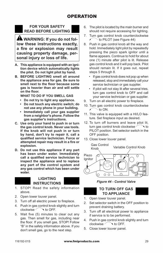
6. The pilot is located by the main burner and should not require accessing for lighting.
7. Turn gas control knob counterclockwise to PILOT (see Figure 44)
8. Push in gas control knob all the way and hold. Immediately light pilot by repeatedly pressing the piezo spark ignitor until a flame appears. Continue to hold for about one (1) minute after pilot is lit. Release gas control knob and it will pop back. Pilot should remain lit. If it goes out, repeat steps 5 through 8.• If gas control knob does not pop up when
released, stop and immediately call your service technician or gas supplier.
• If pilot will not stay lit after several tries, turn gas control knob to OFF and call your service technician or gas supplier.
9. Turn on all electric power to fireplace.10. Turn gas control knob counterclockwise
to ON.11. This valve is equipped with a HI/LO fea-
ture. Set fireplace input as desired.12. To turn off burners and leave pilot lit,
turn gas control knob clockwise to PILOT position. Set selector switch in the OFF position.
13. Close lower louver panel.
OF
F PILOT
LO
IH
ON
Figure 44 - Control Valve
Piezo Ignitor
Gas Control Knob Variable Control Knob
TO TURN OFF GAS TO APPLIANCE
1. Open lower louver panel.2. Set selector switch in the OFF position to
prevent draining battery.3. Turn off all electrical power to appliance
if service is to be performed.4. Push in gas control knob slightly and turn
clockwise to OFF.5. Close lower louver panel.
OPERATION
FOR YOUR SAFETY READ BEFORE LIGHTING
WARNING: If you do not fol-low these instructions exactly, a fire or explosion may result causing property damage, per-sonal injury or loss of life.
A. This appliance is equipped with an igni-tion device which automatically lights the pilot. Do not light pilot by hand.
B. BEFORE LIGHTING smell all around the appliance area for gas. Be sure to smell next to the floor because some gas is heavier than air and will settle on the floor.
WHAT TO DO IF YOU SMELL GAS• Do not try to light any appliance.• Do not touch any electric switch; do
not use any phone in your building.• Immediately call your gas supplier
from a neighbor's phone. Follow the gas supplier's instructions.
C. Use only your hand to push in or turn the gas control knob. Never use tools. If the knob will not push in or turn by hand, don't try to repair it, call a qualified service technician. Force or attempted repair may result in a fire or explosion.
D. Do not use this appliance if any part has been under water. Immediately call a qualified service technician to inspect the appliance and to replace any part of the control system and any gas control which has been under water.
LIGHTING INSTRUCTIONS
1. STOP! Read the safety information above.
2. Open lower louver panel.3. Turn off all electric power to fireplace.4. Push in gas control knob slightly and turn
clockwise to OFF.5. Wait five (5) minutes to clear out any
gas. Then smell for gas, including near the floor. If you smell gas, STOP! Follow “B” in the safety information above. If you don't smell gas, go to the next step.

www.fmiproducts.com 116192-01S30
OPERATIONContinued
MANUAL LIGHTING PROCEDURE
1. Remove glass door (see Removing/Replac-ing Glass Door, page 26).
2. Follow steps 1 through 8 under Lighting Instructions, page 29.
3. Press gas control knob and light pilot with match.
4. Keep gas control knob pressed in for 30 seconds after lighting pilot. After 30 seconds, release gas control knob. Fol-low steps 9 through 12 under Lighting Instructions, page 29.
5. Replace glass door (see Removing/Replac-ing Glass Door, page 26).
OPTIONAL HAND-HELD REMOTE OPERATION
Note: All remote control accessories must be purchased separately (see Accessories, page 38). Follow instructions included with the remote control.
NOTICE: You must light the pilot before using the hand-held re-mote control unit. See Lighting Instructions, page 29.
After lighting, let pilot flame burn for about one minute. Turn control knob to the ON position. Adjust flame adjustment knob anywhere be-tween HI and LO. Slide selector switch to the REMOTE position (see Figure 45).Note: The burner may light if hand-held re-mote was on when selector switch was last turned off. You can now turn burner on and off with hand-held remote control unit.IMPORTANT: Do not leave selector switch in the REMOTE or ON position when pilot is not lit. This will drain the battery.
Figure 45 - Setting Selector Switch, Gas Control Knob and Variable Control Knob
for Remote Operation
OFF PILOT
LO IH
ON
OF
FR
EM
OT
E
ONOFF
O
N
Blower Control Knob (Optional Accessory) Variable
Control Knob
Selector Switch in Remote Position
Gas Control Knob in ON Position
OPERATING OPTIONAL BLOWER ACCESSORY
Locate the blower controls by opening the lower louver panel on the fireplace. Blower controls are located on the right side of the switch bracket to the left just inside the louver panel.The BK manual blower and the BKT ther-mostatically-controlled blower have an ON setting and an OFF setting. The blower will only run when the switch is in the ON posi-tion. In the OFF position, the blower will not operate.Note for BKT Only: If you are using BKT blower with optional thermostat (wall mounted or remote control) for the fireplace, your fire-place and blower will not turn on and off at the same time. The fireplace may run for several minutes before the blower turns on. After the fireplace modulates to the pilot position, the blower will continue to run. The blower will shut off after the firebox temperature decreases.The blower helps distribute heated air from the fireplace. Periodically check the louvers of the firebox and remove any dust, dirt or other obstructions that will hinder the flow of air.

www.fmiproducts.com116192-01S 31
INSPECTING BURNERSCheck pilot flame pattern and burner flame patterns often.PILOT ASSEMBLYThe pilot assembly is factory preset for the proper flame height. Alterations may have occurred during shipping and handling. Call a qualified service person to readjust the pilot if necessary.The height of the thermopile must be 3/8" to 1/2" above the pilot flame as shown in Figure 46. The thermocouple must be at a height of about 1/8" above the pilot flame. The flame from the pilot burner must extend beyond both the thermocouple and thermopile.If you pilot assembly does not meet these requirements:• turn fireplace off (see To Turn Off Gas to
Appliance, page 29)• see Troubleshooting, page 33
Figure 46 - Pilot Assembly
ThermocoupleThermopile
1/8"
Pilot Burner
Piezo Ignitor
3/8" to 1/2"
BURNER FLAME PATTERNBurner flames will be steady, not lifting or float-ing. Flame patterns will be different from unit to unit and will vary depending on installation type and weather conditions.If the vent configuration is installed incorrectly, flames will lift or "ghost". This can be danger-ous. Inspect flames after installation to ensure proper installation and performance. Figure 50 shows a typical flame pattern.If burner flame pattern differs from that de-scribed:• turn fireplace off (see To Turn Off Gas to
Appliance, page 29) • see Troubleshooting, page 33
Figure 47 - Typical Flame Pattern
CLEANING AND MAINTENANCE
WARNING: Turn off fireplace and let cool before cleaning.
CAUTION: You must keep control areas, burners and circulating air passageways of fireplace clean. Inspect these areas of fireplace before each use. Have fireplace inspected yearly by a qualified service person. Fireplace may need more frequent cleaning due to excessive lint from carpeting, bedding material, pet hair, etc.
GLASS DOOR
WARNING: Handle glass door panel with care. Do not strike, slam or otherwise abuse glass. Do not operate fireplace with the glass door unlatched, removed, cracked or broken.
WARNING: Do not use abrasive cleaners as this may damage glass. Use a nonabra-sive household glass cleaner to clean glass. Do not clean glass when hot.
Glass must be cleaned periodically. During start-up it is normal for condensation to form on the inside of the glass causing lint, dust and other airborne particles to cling to the glass surface. During initial start-up a slight film may form on the glass due to paint curing. The glass should be cleaned several times with a non-ammonia, nonabrasive household clean-er and warm water after the first two weeks of operation. Thereafter, clean the glass two or three times during each heating season, depending on the usage and circumstances present. Refer to Removing/Replacing Glass Door, page 26 of this manual when removing glass door for cleaning.

www.fmiproducts.com 116192-01S32
WARNING: Only parts sup-plied by the manufacturer should be used when replacing broken or damaged glass door panel (see Replacement Parts, page 37). This glass door panel is a complete unit. No substitute materials may be used.
CAUTION: Wear gloves and safety glasses while handling or removing broken glass. Do not remove if glass is hot. Keep children and pets away from glass.
If glass has been broken, carefully remove glass door (see Removing/Replacing Glass Door, page 26). Vacuum all glass pieces with a shop vac.
CAUTION: Do not vacuum if pieces are hot.
Use only the tempered glass door replace-ment intended for this fireplace (see Replace-ment Parts, page 37 for detail on ordering). No substitutions may be made. See Removing/Replacing Glass Door, page 26 for instruc-tions for replacing glass door.
WARNING: Do not operate fireplace with the glass door unlatched, removed, cracked or broken.
PILOT AND BURNERS• Remove ember material before cleaning
burners and replace when cleaning is complete.
• Burner and controls should be cleaned with compressed air to remove dust, dirt or lint.
• Use a vacuum cleaner or small, soft bristled brush to remove excess dust, dirt or lint.
LOGS• If you remove logs for cleaning, refer to
Installing Lava Rock and Glowing Embers, page 27, to properly replace logs.
• Use a vacuum cleaner to remove any carbon buildup on logs.
• Replace log(s) if broken. See Replacement Parts on page 37.
• Replace ember material periodically as needed. See Replacement Parts on page 37.
VENTING SYSTEMConduct annual inspection of the venting system following these guidelines:1. Check areas of venting system that are
exposed to the weather for corrosion (rust spots or streaks and, in extreme cases, holes). Have these items replaced im-mediately by a qualified service person.
2. Remove the vent cap and shine a flash-light into the vent. Remove any foreign material.
3. Check for evidence of excessive con-densation. Continuous condensation can cause corrosion of caps, pipes and fittings and can be caused by having excessive lateral runs, too many elbows or exterior portions of the system being exposed to cold weather.
4. Inspect joints to verify that no pipe section or fitting has been disturbed and loos-ened. Check mechanical supports such as wall straps for rigidity.
CLEANING AND MAINTENANCEContinued

www.fmiproducts.com116192-01S 33
TROUBLESHOOTING
WARNING: Turn off fireplace and let cool before servicing. Only a qualified service person should service and repair fireplace.
CAUTION: Never use a wire, needle or similar object to clean pilot. This can damage pilot unit.
Note: All troubleshooting items are listed in order of operation.
POSSIBLE CAUSE1. Ignitor electrode not con-
nected to ignitor cable2. Ignitor cable pinched or
wet
3. Piezo ignitor nut is loose
4. Broken ignitor cable5. Bad piezo ignitor6. Ignitor electrode broken7. Ignitor electrode positioned
wrong
1. Gas supply turned off or equipment shutoff valve closed
2. Gas control knob not in PILOT position
3. Gas control knob not pressed in while in PILOT position
4. Air in gas lines when in-stalled
5. Depleted gas supply (pro-pane/LP models only)
6. Pilot is clogged
7. Gas regulator setting is not correct
REMEDY1. Reconnect ignitor cable
2. Free ignitor cable if pinched by any metal or tubing. Keep ignitor cable dry
3. Tighten nut holding piezo ignitor. Nut is located be-hind the mounting bracket
4. Replace ignitor cable5. Replace piezo ignitor 6. Replace pilot assembly7. Tighten electrode. Replace
if necessary
1. Turn on gas supply or open equipment shutoff valve
2. Turn gas control knob to PILOT position
3. Press in gas control knob while in PILOT position
4. Continue holding down control knob. Repeat ig-niting operation until air is removed
5. Contact local propane/LP gas company
6. Clean pilot (see Cleaning and Maintenance, page 31) or replace pilot as-sembly
7. Replace gas regulator
OBSERVED PROBLEMWhen ignitor button is pressed, there is no spark at pilot
When ignitor button is pressed, there is spark at pilot but no ignition

www.fmiproducts.com 116192-01S34
OBSERVED PROBLEMPilot lights but flame goes out when control knob is released
Burner does not light after pilot is lit
Delayed ignition burner
Burner backfiring during combustion
Slight smoke or odor during initial operation
REMEDY1. Press in gas control knob
fully2. After pilot lights, keep gas
control knob pressed in 30 seconds
3. Fully open equipment shut-off valve
4. A) Contact local natural or propane/LP gas company
B) Clean pilot (see Clean-ing and Maintenance, page 31) or replace pilot assembly
5. Hand tighten until snug, then tighten 1/4 turn more
6. Replace pilot assembly7. Replace control valve
1. Clean burner (see Clean-ing and Maintenance , page 31) or replace burner orifice
2. Contact local propane/LP or natural gas company
3. Reconnect leads to TP & TPTH terminals on control valve
4. Replace thermopile
1. Contact local propane/LP or natural gas company
2. Clean burner (see Clean-ing and Maintenance , page 31) or replace burner orifice
1. Clean burner (see Clean-ing and Maintenance , page 31) or replace burner orifice
2. Replace damaged burner3. Replace gas control
1. Problem will stop after a few hours of operation
TROUBLESHOOTINGContinued
POSSIBLE CAUSE1. Gas control knob not fully
pressed in2. Gas control knob not
pressed in long enough
3. Equipment shutoff valve not fully open
4. Pilot flame not touching thermocouple, which al-lows thermocouple to cool, causing pilot flame to go out. This problem could be caused by one or both of the following:
A) Low gas pressure B) Dirty or partially clogged
pilot5. Thermocouple connection
loose at control valve 6. Thermocouple damaged7. Control valve damaged
1. Burner orifice clogged
2. Inlet gas pressure is too low
3. Thermopile leads discon-nected or improperly con-nected
4. Thermopile is defective
1. Manifold pressure is too low
2. Burner porting or orifice clogged
1. Burner orifice is clogged or damaged
2. Damaged burner3. Gas regulator defective
1. Residues from manufac-turing processes and logs curing

www.fmiproducts.com116192-01S 35
TROUBLESHOOTINGContinued
OBSERVED PROBLEMFireplace produces a whis-tling noise when burner is lit
Glass soots
Fireplace produces a clicking/ticking noise just after burners are lit or shut off
Remote does not function
Dark residue on logs or inside of fireplace
REMEDY1. Turn gas control knob to
LO position and let warm up for a minute
2. Operate burner until air is removed from line. Have gas line checked by local propane/LP or natural gas company
3. Clean burner (see Clean-ing and Maintenance , page 31) or replace burner orifice
1. Inspect the opening at the base of the burner by re-moving log/grate assembly to see that it is NOT packed with any type of material [see Installing Brick Liner Models BL36DA(SA) and BL36DHA(SA), page 28] for log/grate removal
2. Check vent configuration specifications (see Venting Installation, page 10)
1. This is normal. If noise is excessive, contact quali-fied service person
1. Replace 9-volt batteries in receiver and hand-held remote control
1. Clean out air holes at burner inlets. Periodically repeat as needed
2. Remove blockage or re-place burner
3. Have vent system inspect-ed, including termination cap. Remove any restric-tions or obstruction
4. Clear excess embers until a minimum gap of 1/2" remains under the grate
POSSIBLE CAUSE1. Turning gas control knob to
HI position when burner is cold
2. Air in gas line
3. Dirty or partially clogged burner orifice
1. Debris around burner air mixer
2. Improper vent configura-tion
1. Metal expanding while heating or contracting while cooling
1. Battery is not installed or battery power is low
1. Air holes at burner inlet blocked
2. B u r n e r f l a m e h o l e s blocked
3. Improper venting or exces-sive blockage
4. Excessive amounts of embers and pan material
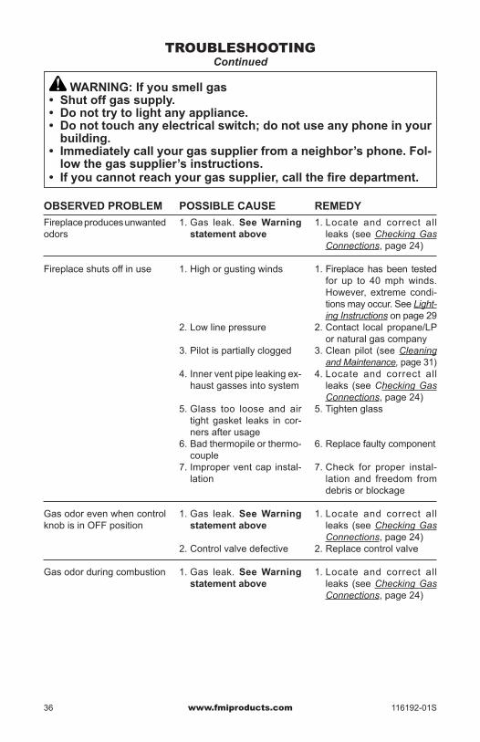
www.fmiproducts.com 116192-01S36
TROUBLESHOOTINGContinued
WARNING: If you smell gas• Shut off gas supply.• Do not try to light any appliance.• Do not touch any electrical switch; do not use any phone in your
building.• Immediately call your gas supplier from a neighbor’s phone. Fol-
low the gas supplier’s instructions.• If you cannot reach your gas supplier, call the fire department.
POSSIBLE CAUSE1. Gas leak. See Warning
statement above
1. High or gusting winds
2. Low line pressure
3. Pilot is partially clogged
4. Inner vent pipe leaking ex-haust gasses into system
5. Glass too loose and air tight gasket leaks in cor-ners after usage
6. Bad thermopile or thermo-couple
7. Improper vent cap instal-lation
1. Gas leak. See Warning statement above
2. Control valve defective
1. Gas leak. See Warning statement above
OBSERVED PROBLEMFireplace produces unwanted odors
Fireplace shuts off in use
Gas odor even when control knob is in OFF position
Gas odor during combustion
REMEDY1. Locate and correct all
leaks (see Checking Gas Connections, page 24)
1. Fireplace has been tested for up to 40 mph winds. However, extreme condi-tions may occur. See Light-ing Instructions on page 29
2. Contact local propane/LP or natural gas company
3. Clean pilot (see Cleaning and Maintenance, page 31)
4. Locate and correct all leaks (see Checking Gas Connections, page 24)
5. Tighten glass
6. Replace faulty component
7. Check for proper instal-lation and freedom from debris or blockage
1. Locate and correct all leaks (see Checking Gas Connections, page 24)
2. Replace control valve
1. Locate and correct all leaks (see Checking Gas Connections, page 24)

www.fmiproducts.com116192-01S 37
SPECIFICATIONSTC36N, VTC36N, TCC36N, VTCC36N• Rating: 18,000/26,000 Btu/hr• Gas Type: Natural Gas Only• Ignition: Piezo• Manifold Pressure: 3.5" w.c.• Minimum Inlet Supply Pressure: 5.5" w.c.• Firebox Dimensions (HxWxD) (Flanges and
Standoffs Not Included in Measurement): 36" x 41" x 21 1/8" (91 x 104 x 54 cm)
TC36N-HA, VTC36N-HA, TCC36N-HA, VTCC36N-HA, CTDV36NR-HA• Rating: 18,000/26,000 Btu/hr• Gas Type: Natural Gas Only• Ignition: Piezo• Manifold Pressure: 3.8" w.c.• Minimum Inlet Supply Pressure: 5.5" w.c.• Firebox Dimensions (HxWxD) (Flanges and
Standoffs Not Included in Measurement): 36" x 41" x 21 1/8" (91 x 104 x 54 cm)
TC36P VTC36P, TCC36P, VTCC36P• Rating: 17,000/24,000 Btu/hr• Gas Type: Propane/LP Gas Only• Ignition: Piezo• Manifold Pressure: 10" w.c.• Minimum Inlet Supply Pressure: 11" w.c.• Firebox Dimensions (HxWxD) (Flanges and
Standoffs Not Included in Measurement): 36" x 41" x 21 1/8" (91 x 104 x 54 cm)
REPLACEMENT PARTSNote: Use only original replacement parts. This will protect your warranty coverage for parts replaced under warranty.Contact authorized dealers of this product. If they can’t supply original replacement part(s), call FMI PRODUCTS, LLC at 1-866-328-4537.
When calling, have ready:• your name• your address• model and serial numbers of your fireplace• how fireplace was malfunctioning• purchase dateUsually, we will ask you to return the part to the factory.
SERVICE HINTSWhen Gas Pressure Is Too Low• pilot will not stay lit• burners will have delayed ignition• fireplace will not produce specified heat• propane/LP gas supply might be low (pro-
pane/LP units only)You may feel your gas pressure is too low. If so, contact your local gas supplier.
TECHNICAL SERVICEYou may have further questions about installation, operation, or troubleshooting. If so, contact FMI PRODUCTS, LLC at 1-866-328-4537. When calling please have your model and serial numbers of your fireplace ready.You can also visit our web site at www.fmiproducts.com.

www.fmiproducts.com 116192-01S38
ACCESSORIES
NOTICE: All accessories may not be available for all fireplace models.
Purchase these accessories from your local dealer. If they can not supply these accessories call FMI PRODUCTS, LLC at 1-866-328-4537 for information. You can also write to the ad-dress listed on the back page of this manual.
BRICK LINER KITBL36D-A - Textured RefractoryBL36DS-A - Standard RefractoryBL36DH-A - Textured Refractory HerringboneBL36DHS-A - Standard Refractory HerringboneBLX36STL - Ledgestone Refractory KitBLX36SVF - Fiber Liner KitPLX36 - Porcelain Liner KitThis brick liner adds a touch of style to your direct-vent fireplace. Complete installation instructions included in this manual.
PROPANE/NATURAL GAS CONVERSION KITPCDM-36TC - Propane/LP GasNCDM-36TC - Natural Gas
FILIGREE FACE/LOUVER PANEL KITFPD36 - BlackFPD36B - Brushed BrassFPD36P - Platinum
ROLLED LOUVER TRIM KITLT36B - Brushed BrassLT36P - Platinum
DEFLECTION HOODHD36 - Black (2" Brow)
PERIMETER TRIM KITPT36 - BlackPT36B - Brushed BrassPT36P - Platinum

www.fmiproducts.com116192-01S 39
THERMOSTATICALLY- CONTROLLED BLOWER KIT - BKTProvides better heat distribution. Blower turns off and on automatically, as needed. Com-plete installation and operation instructions included in this manual.
MANUAL BLOWER KIT - BKManual variable control blower accessory provides better heat distribution. Complete in-stallation and operation instructions included in this manual.
RECEIVER AND HAND-HELD ON/OFF REMOTE CONTROL KIT - MRC Allows the fireplace to be turned on and off conveniently.
WALL MOUNTED ON/OFF SWITCH GWMS2Allows burner system to be turned on and off with a wall switch.
ON
OFF
ACCESSORIESContinued

www.fmiproducts.com 116192-01S40
PARTSMODELS (V)TC36N, (V)TCC36N, (V)TC36P, (V)TCC36P SERIES AND CTDV36NR-HA
23
24
6
7
20
17
18
13
2
12 19
8
14
11
9
14
3
16
5
15
21
10
22
26
26
27
27
25

www.fmiproducts.com116192-01S 41
PARTSThis list contains replaceable parts used in your fireplace. When ordering parts, follow the instructions listed under Replacement Parts on page 37 of this manual.
KEY NO. PART NO. DESCRIPTION QTY.1 ** Firebox Assembly • • 12 ** Face Weldment • • 13 108010-01 Door Assembly • • 1
108010-02 Door Assembly (V Models Only) • • 14 108011-01 Top Louver Assembly • 15 108011-02 Bottom Louver Assembly • 16 ** Fireplace Top • • 17 ** Fireplace Top Insulation • • 18 ** Fireplace Surround • • 19 109082-01 Heat Shield • • 110 116214-01 Log Set Assembly • • 111 110989-01 Left Refractory Brick Panel, VTC/VTCC36 models • • 1
110989-02 Left Refractory Brick Panel, TC/TCC36 models • • 112 110991-01 Rear Refractory Brick Panel, VTC/VTCC36 models • • 1
110991-02 Rear Refractory Brick Panel, TC/TCC36 models • • 113 110990-01 Right Refractory Brick Panel, VTC/VTCC36 models • • 1
110990-02 Right Refractory Brick Panel, TC/TCC36 models • • 114 108719-01 Screen Rod • 115 12105 Screen • 216 11418 Push-On Nut • 217 14123 Strain Relief • • 118 21171 Gas Knock-Out Cover • • 219 24353 Handy Box Assembly • • 120 24460 Gas Conduit Assembly • • 121 116209-01 Burner Assembly NG (see page 40) • • 1
116209-02 Burner Assembly LP (see page 40) • • 1116209-05 Burner Assembly (HA Models) see page 40 • • 1
22 116373-01 Plenum • • 123 118372-01 Top Pilot Shield • • 124 120945-01 Bottom Pilot Shield • • 125 125408-02 Screen Door • 126 125519-01 Door Latch Magnet • 227 125558-01 Door Latch Screw • 8
PARTS AVAILABLE - NOT SHOWN25487 Lava Rock/Bag Assembly • • 127253 Notice Label • • 155240 Vent Label • • 1PCDM-36TC Propane/LP Gas Conversion Kit
(model CTDV36NR-HA only)• 1
** Not a field replaceable part.
TC36
TCC3
6
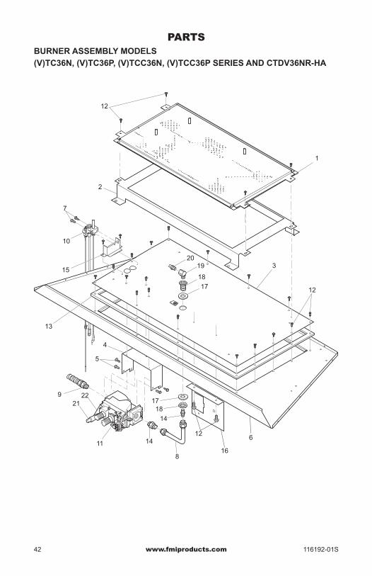
www.fmiproducts.com 116192-01S42
PARTSBURNER ASSEMBLY MODELS(V)TC36N, (V)TC36P, (V)TCC36N, (V)TCC36P SERIES AND CTDV36NR-HA
7
15
10
12
1
12
2
3
13
9
11
2122
TPTH T
P TH
612
14
1817
17
18
1920
16
14
8
4
5

www.fmiproducts.com116192-01S 43
PARTSThis list contains replaceable parts used in your fireplace. When ordering parts, follow the instructions listed under Replacement Parts on page 37 of this manual.
KEY NO. PART NO. DESCRIPTION QTY.1 ** Burner Pan Assembly 12 ** Base Grate 13 ** Firebox Base Bottom 14 26808 Valve Bracket 15 11107 Screw, #10-32 x 1/4 Zinc 46 ** Firebox Bottom 17 11102 Screw, #8-32 x 3/8 Zinc 28 121877-01 Aluminum Tubing Assembly 19 111288-02 Flex Gas Line 110 108084-02 Pilot Assembly NG 1
108084-03 Pilot Assembly LP 1108084-05 Pilot Assembly (-HA Models) 1
11 14389 Natural Gas Valve 114390 Propane/LP Gas Valve 1117370-01 Natural Gas High Altitude Valve 1
12 11165 Screw, #10 x 5/8 Zinc 2313 ** Burner Base Gasket 114 14500 Brass Fitting 215 116345-01 Pilot Bracket 116 26827 Switch Bracket 117 11226 Flat Washer 7/8" ID x 2" OD 218 11214 Bulkhead Fitting with Washer 219 14296 Elbow 3/8" 120 23102 Burner Orifice #40 NG 1
23096 Burner Orifice #53 LP 121 14492 Piezo Ignitor 122 14511 Piezo Bracket 1
PARTS AVAILABLE - NOT SHOWN108085-03 Pilot Injector #62 (-HA Models Only) 1
**Not a field replaceable part.

116192-01Rev. S04/13
WARRANTYKEEP THIS WARRANTY
FMI PRODUCTS, LLC LIMITED WARRANTIESNew Products
Standard Warranty: FMI PRODUCTS, LLC warrants this new product and any parts thereof to be free from defects in material and workmanship for a period of four (4) years from the date of first purchase from an authorized dealer provided the product has been installed, maintained and operated in accordance with FMI PRODUCTS, LLC’s warnings and instructions.For products purchased for commercial, industrial or rental usage, this warranty is limited to 90 days from the date of first purchase.
Factory Reconditioned ProductsLimited Warranty: FMI PRODUCTS, LLC warrants factory reconditioned products and any parts thereof to be free from defects in material and workmanship for 30 days from the date of first purchase from an authorized dealer provided the product has been installed, maintained and operated in accordance with FMI PRODUCTS, LLC’s warnings and instructions.
Terms Common to All WarrantiesThe following terms apply to all of the above warranties:Always specify model number and serial number when contacting the manufacturer. To make a claim under this warranty the bill of sale or other proof of purchase must be presented.This warranty is extended only to the original retail purchaser when purchased from an authorized dealer, and only when installed by a qualified installer in accordance with all local codes and instructions furnished with this product.This warranty covers the cost of part(s) required to restore this product to proper operating condition and an allow-ance for labor when provided by a FMI PRODUCTS, LLC Authorized Service Center or a provider approved by FMI PRODUCTS, LLC. Warranty parts must be obtained through authorized dealers of this product and/or FMI PRODUCTS, LLC who will provide original factory replacement parts. Failure to use original factory replacement parts voids this warranty.Travel, handling, transportation, diagnostic, material, labor and incidental costs associated with warranty repairs, unless expressly covered by this warranty, are not reimbursable under this warranty and are the responsibility of the owner.All warranty will be voided if this product is used with a thermostat.Excluded from this warranty are products or parts that fail or become damaged due to misuse, accidents, improper installation, lack of proper maintenance, tampering, or alteration(s).This is FMI PRODUCTS, LLC’s exclusive warranty, and to the full extent allowed by law; this express warranty excludes any and all other warranties, express or implied, written or verbal and limits the duration of any and all implied warranties, including warranties of merchantability and fitness for a particular purpose to four (4) years on new products and 30 days on factory reconditioned products from the date of first purchase. FMI PRODUCTS, LLC makes no other warranties regarding this product.FMI PRODUCTS, LLC’s liability is limited to the purchase price of the product, and FMI PRODUCTS, LLC shall not be liable for any other damages whatsoever under any circumstances including indirect, incidental, or consequential damages.Some states do not allow limitations on how long an implied warranty lasts or the exclusion or limitation of incidental or consequential damages, so the above limitation or exclusion may not apply to you. This warranty gives you specific legal rights, and you may also have other rights which vary from state to state. For information about this warranty contact:
Model (located on product or identification tag) _____________________________
Serial No. (located on product or identification tag) __________________________
Date Purchased __________________________
Keep receipt for warranty verification.
2701 S. Harbor Blvd.Santa Ana, CA 92704
1-866-328-4537www.fmiproducts.com