Embed Size (px)
Citation preview

Diploma ThesisJune 12, 2006
Reengineering of aTicket Sales System
Alex Mullerof Schaffhausen, Switzerland (99-808-214)
supervised by
Prof. Dr. Harald GallBeat Fluri
Department of Informatics software evolution & architecture lab


Diploma Thesis
Reengineering of aTicket Sales System
Alex Muller
Department of Informatics software evolution & architecture lab

Diploma Thesis
Author: Alex Muller, [email protected]
Project period: December 12, 2005 - June 12, 2006
Software Evolution & Architecture Lab
Department of Informatics, University of Zurich

Acknowledgements
I would like to thank all the people involved in the success of this thesis—they were always help-ful and devoted their time to my issues. This includes the people at the Institute for Informaticsat the University of Zurich, the company I did this thesis in conjunction with, and my family andfriends. Special thanks go to Professor Harald Gall for mounting this practically oriented thesis,Beat Fluri for supporting me in the reengineering tool jungle and helping me out with miscella-neous problems during the thesis every day life, Helmut Rainel and Andreas Schabmann fromthe company for taking the risk of giving a valuable software asset into the hands of a student,and the senior developer Oliver Honigsberger for taking the time to answer a large number ofquestions related to the software component under investigation. I am also grateful to my par-ents and my girlfriend which looked after me in terms of motivation and healthy food every oncein a while. Last but not least, I am very pleased about the philosophy of open source software,which I used intensively during the thesis.


Abstract
The goal of this diploma thesis is to develop a reengineering plan for the front-end of a ticketsales system written in Java using reengineering techniques and tools. The front-end componentis operational, but defect from a maintenance point of view. The analysis of the component andthe change propositions are based on theoretical cognitions, practically established reengineeringpatterns, and supporting software tools. Elements of these domains are applied in the reengineer-ing process to find a best practice solution for the given task. The thesis leads through the reverseand forward engineering process. It is organized in three parts. The first part gives an overview tothe software reengineering domain and introduces the instruments used in the thesis. The secondpart covers the reverse engineering of the component. A stepwise organized and goal-orientedanalysis process supported by object-oriented reverse engineering patterns and tools is applied.The result of the second part is the set of classes that need to be reengineered. The third part dis-cusses the options based on the reverse engineering results and delivers a goal architecture anda plan describing how to change the ticket sales component to make it easier to maintain and toenable its further evolution.


Zusammenfassung
Das Ziel dieser Diplomarbeit ist das Entwerfen eines Reengineeringplans fur ein in Java geschrie-benes Front-End eines Ticketverkaufsystems. Das Front End ist in Gebrauch, aber defekt ausder Wartungsperspektive. Die Analyse der Komponente und die Anderungsvorschlage basierenauf theoretischen Erkenntnissen, praktisch bewahrten Reengineering Mustern und hilfreichenSoftware Tools. Die Elemente werden wahrend dem Reengineeringprozess angewendet um einebestmogliche Losung des gestellten Problems zu erarbeiten. Die Diplomarbeit fuhrt durch denReverse- und den Forwardengineeringprozess. Die Arbeit ist in drei Teile gegliedert. Der er-ste Teil gibt eine Ubersicht zum Software Reengineering und stellt die im Verlaufe der Arbeitangewendeten Instrumente vor. Der zweite Teil dokumentiert den Analysevorgang der Kom-ponente. Ein schrittweise organisierter und zielgerichteter Analyseprozess begleitet von objek-torientierten Reverse Engineering Mustern und Software Tools wird durchlaufen. Das Resultatdes zweiten Teils sind die identifizierten Klassen, die einem Reengineering unterzogen werdenmussen. Der dritte Teil diskutiert Optionen aufgrund der Analyseresultate und gibt eine Zielar-chitektur vor. Ein Plan beschreibt welche Veranderungen an der Komponente vorgenommen wer-den mussen um die Wartbarkeit zu vereinfachen und um eine weitere Evolution zu ermoglichen.

Contents
1 Introduction 11.1 The Patient . . . . . . . . . . . . . . . . . . . . . . . . . . . . . . . . . . . . . . . . . . 11.2 Goals . . . . . . . . . . . . . . . . . . . . . . . . . . . . . . . . . . . . . . . . . . . . . 11.3 A Brief History of Software Reengineering . . . . . . . . . . . . . . . . . . . . . . . 21.4 Object-Oriented Legacy Systems . . . . . . . . . . . . . . . . . . . . . . . . . . . . . 21.5 Structure of the Thesis . . . . . . . . . . . . . . . . . . . . . . . . . . . . . . . . . . . 3
2 Reengineering Methodology 52.1 Reengineering Terminology . . . . . . . . . . . . . . . . . . . . . . . . . . . . . . . . 52.2 Reengineering Patterns . . . . . . . . . . . . . . . . . . . . . . . . . . . . . . . . . . . 62.3 Patterns and the Reengineering Life Cycle . . . . . . . . . . . . . . . . . . . . . . . . 82.4 Refactorings . . . . . . . . . . . . . . . . . . . . . . . . . . . . . . . . . . . . . . . . . 102.5 Software Reengineering Tools . . . . . . . . . . . . . . . . . . . . . . . . . . . . . . . 11
2.5.1 Creole for Code Visualization . . . . . . . . . . . . . . . . . . . . . . . . . . . 122.5.2 CodeCrawler for Metrics Visualizations . . . . . . . . . . . . . . . . . . . . . 122.5.3 Omondo UML for an Abstract View of the Classes . . . . . . . . . . . . . . . 142.5.4 Java Metrics to Collect Relevant Metrics of the System . . . . . . . . . . . . 142.5.5 Eclipse for Automated Refactorings . . . . . . . . . . . . . . . . . . . . . . . 14
3 Reverse Engineering 173.1 Setting Direction . . . . . . . . . . . . . . . . . . . . . . . . . . . . . . . . . . . . . . . 173.2 First Contact . . . . . . . . . . . . . . . . . . . . . . . . . . . . . . . . . . . . . . . . . 18
3.2.1 Interview during Demo . . . . . . . . . . . . . . . . . . . . . . . . . . . . . . 193.2.2 Chat with the Maintainers . . . . . . . . . . . . . . . . . . . . . . . . . . . . . 213.2.3 Skim the Documentation . . . . . . . . . . . . . . . . . . . . . . . . . . . . . 233.2.4 Read All the Code in One Hour . . . . . . . . . . . . . . . . . . . . . . . . . . 243.2.5 Do a Mock Installation . . . . . . . . . . . . . . . . . . . . . . . . . . . . . . . 253.2.6 Summary of the First Contact . . . . . . . . . . . . . . . . . . . . . . . . . . . 25
3.3 Initial Understanding . . . . . . . . . . . . . . . . . . . . . . . . . . . . . . . . . . . . 253.3.1 Speculate about Design . . . . . . . . . . . . . . . . . . . . . . . . . . . . . . 263.3.2 Study the Exceptional Entities . . . . . . . . . . . . . . . . . . . . . . . . . . 323.3.3 Summary of Initial Understanding . . . . . . . . . . . . . . . . . . . . . . . . 38
3.4 Detailed Reengineering Definition . . . . . . . . . . . . . . . . . . . . . . . . . . . . 393.5 Detailed Model Capture . . . . . . . . . . . . . . . . . . . . . . . . . . . . . . . . . . 41
3.5.1 Step through the Execution . . . . . . . . . . . . . . . . . . . . . . . . . . . . 413.5.2 Look for the Contracts . . . . . . . . . . . . . . . . . . . . . . . . . . . . . . . 473.5.3 Detailed Model Capture Summary . . . . . . . . . . . . . . . . . . . . . . . . 49
3.6 Reverse Engineering Results . . . . . . . . . . . . . . . . . . . . . . . . . . . . . . . . 50

viii CONTENTS
4 Reengineering Options 514.1 Rebuild from Scratch? . . . . . . . . . . . . . . . . . . . . . . . . . . . . . . . . . . . 514.2 Alternatives to Java . . . . . . . . . . . . . . . . . . . . . . . . . . . . . . . . . . . . . 514.3 Graphical User Interfaces . . . . . . . . . . . . . . . . . . . . . . . . . . . . . . . . . 52
4.3.1 GUI Principles . . . . . . . . . . . . . . . . . . . . . . . . . . . . . . . . . . . 524.3.2 GUI Creation Frameworks . . . . . . . . . . . . . . . . . . . . . . . . . . . . 53
4.4 Unit Tests . . . . . . . . . . . . . . . . . . . . . . . . . . . . . . . . . . . . . . . . . . . 544.5 Evaluation of the Proceeding . . . . . . . . . . . . . . . . . . . . . . . . . . . . . . . 55
4.5.1 SWT and JWS together? . . . . . . . . . . . . . . . . . . . . . . . . . . . . . . 554.5.2 View or Controller first? . . . . . . . . . . . . . . . . . . . . . . . . . . . . . . 554.5.3 Mapper or Direct Access to the View? . . . . . . . . . . . . . . . . . . . . . . 56
4.6 Prototype the Target Solution . . . . . . . . . . . . . . . . . . . . . . . . . . . . . . . 574.6.1 Feasibility of JWS Type Substitutions . . . . . . . . . . . . . . . . . . . . . . 574.6.2 Feasibility of the Mapper . . . . . . . . . . . . . . . . . . . . . . . . . . . . . 574.6.3 Feasibility of the Refactorings . . . . . . . . . . . . . . . . . . . . . . . . . . . 58
5 Reengineering Plan 595.1 Overview . . . . . . . . . . . . . . . . . . . . . . . . . . . . . . . . . . . . . . . . . . . 595.2 Substitute Local JWS Elements in Controller . . . . . . . . . . . . . . . . . . . . . . . 595.3 Create JWS Mapper . . . . . . . . . . . . . . . . . . . . . . . . . . . . . . . . . . . . . 595.4 Build SWT GUI . . . . . . . . . . . . . . . . . . . . . . . . . . . . . . . . . . . . . . . 605.5 Controller Refactoring . . . . . . . . . . . . . . . . . . . . . . . . . . . . . . . . . . . 625.6 Documentation . . . . . . . . . . . . . . . . . . . . . . . . . . . . . . . . . . . . . . . 66
6 Conclusions and Outlook 676.1 Contribution . . . . . . . . . . . . . . . . . . . . . . . . . . . . . . . . . . . . . . . . . 676.2 Experiences Made . . . . . . . . . . . . . . . . . . . . . . . . . . . . . . . . . . . . . . 676.3 Outlook . . . . . . . . . . . . . . . . . . . . . . . . . . . . . . . . . . . . . . . . . . . . 67
A Source Code Listings 69A.1 JWS Substitute Data Types . . . . . . . . . . . . . . . . . . . . . . . . . . . . . . . . . 69A.2 Mapper Class . . . . . . . . . . . . . . . . . . . . . . . . . . . . . . . . . . . . . . . . 69A.3 Move Method Refactoring Example . . . . . . . . . . . . . . . . . . . . . . . . . . . 69
B List of Used Software Tools 75

CONTENTS ix
List of Figures
2.1 Graphical overview of the reverse engineering taxonomy. . . . . . . . . . . . . . . . 72.2 The software reengineering life cycle. . . . . . . . . . . . . . . . . . . . . . . . . . . 92.3 Pattern clusters assigned to the reengineering life cycle. . . . . . . . . . . . . . . . . 102.4 Creole view of class interactions and intra class variable accesses. . . . . . . . . . . 132.5 The principle of a polymetric view (a) and a class hierarchy generated by Code-
Crawler using polymetric views (b). . . . . . . . . . . . . . . . . . . . . . . . . . . . 132.6 Example of metric results calculated by the Java Metrics plug-in. . . . . . . . . . . . 15
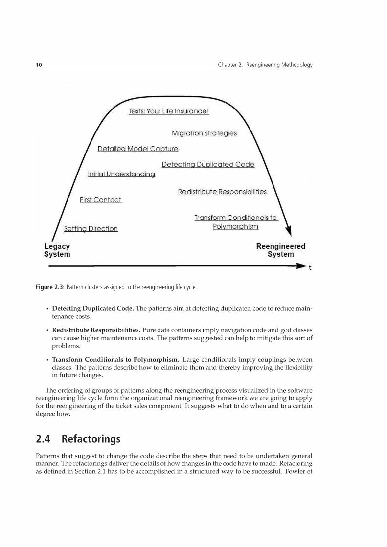
3.1 GUI of the main working surface of the ticket sales component. . . . . . . . . . . . 203.2 Component view of the event managing system. . . . . . . . . . . . . . . . . . . . . 223.3 Communication path of the ticket sales component with the database. . . . . . . . 243.4 An UML class diagram showing inheritance relations. . . . . . . . . . . . . . . . . . 263.5 Typical method call path for handling GUI user input events that trigger database
access. . . . . . . . . . . . . . . . . . . . . . . . . . . . . . . . . . . . . . . . . . . . . 293.6 Hierarchy of classes in the odp package. . . . . . . . . . . . . . . . . . . . . . . . . . 303.7 The class hierarchies of the group package. . . . . . . . . . . . . . . . . . . . . . . . 313.8 Assignment of classes to model, view, or control layer. . . . . . . . . . . . . . . . . . 323.9 Visualization of class hierarchies, interface hierarchies, and interface implementa-
tions in the ticket sales component. . . . . . . . . . . . . . . . . . . . . . . . . . . . . 48
5.1 The architecture of the reengineered ticket sales component. . . . . . . . . . . . . . 605.2 The class hierarchy of the JWS mapper classes. . . . . . . . . . . . . . . . . . . . . . 625.3 UML class diagram of classes that contain methods moved from the form clCache
class. . . . . . . . . . . . . . . . . . . . . . . . . . . . . . . . . . . . . . . . . . . . . . 65
List of Tables
2.1 The format of a reengineering pattern. . . . . . . . . . . . . . . . . . . . . . . . . . . 82.2 A condensed example of a reengineering pattern. . . . . . . . . . . . . . . . . . . . 82.3 Overview of refactoring categories. . . . . . . . . . . . . . . . . . . . . . . . . . . . . 11
3.1 Overview of the patterns used from the setting directions cluster. . . . . . . . . . . . 183.2 Setting direction patterns stating generic rules to keep in mind during the reengi-
neering project. . . . . . . . . . . . . . . . . . . . . . . . . . . . . . . . . . . . . . . . 193.3 First Contact patterns used to get to know the system. . . . . . . . . . . . . . . . . . 193.4 Initial Understanding patterns used to discover the details of the ticket sales compo-
nent. . . . . . . . . . . . . . . . . . . . . . . . . . . . . . . . . . . . . . . . . . . . . . 263.5 Overview of loose classes. . . . . . . . . . . . . . . . . . . . . . . . . . . . . . . . . . 273.6 Abbreviation and full description of the metrics used on the package level. . . . . . 333.7 List of metric values on package level. . . . . . . . . . . . . . . . . . . . . . . . . . . 333.8 Abbreviation, full description, and threshold values of the used class size metrics. 343.9 Classes with exceptional metric values. . . . . . . . . . . . . . . . . . . . . . . . . . 353.10 Manual evaluation summary of classes identified to have exceptional class size
metrics. . . . . . . . . . . . . . . . . . . . . . . . . . . . . . . . . . . . . . . . . . . . . 373.11 Abbreviation and full description used class inheritance metrics. . . . . . . . . . . . 373.12 Significant metric values of class inheritance metrics. . . . . . . . . . . . . . . . . . 383.13 Abbreviation, full description, and thresholds of the used method metrics. . . . . . 38

x CONTENTS
3.14 List of methods having exceptional metrics. . . . . . . . . . . . . . . . . . . . . . . . 393.15 The load the hall map of a chosen event feature split up into steps with the correspond-
ing logic methods. . . . . . . . . . . . . . . . . . . . . . . . . . . . . . . . . . . . . . . 473.16 Interfaces, their implementing classes, their referencing classes, and their purpose. 493.17 Reengineering dealing for the loose classes. . . . . . . . . . . . . . . . . . . . . . . . 503.18 Reengineering dealing for the ODP classes. . . . . . . . . . . . . . . . . . . . . . . . 50
4.1 Line up of SWT and Swing properties. . . . . . . . . . . . . . . . . . . . . . . . . . . 54
5.1 Overview of the reengineering plan including milestones. . . . . . . . . . . . . . . 615.2 List of JWS types in the controller that need to be substituted. . . . . . . . . . . . . 615.3 Subjects representing new classes to split up the form clCache class. . . . . . . . 645.4 Methods that need to moved to an existing class or a substitute thereof. . . . . . . . 65
List of Listings
3.1 A snippet of debug information obtained when loading the hall map for an event. 443.2 A snippet of the debug information with added print statements obtained for the
form clCache class when loading the hall map for an event. . . . . . . . . . . . . 453.3 Code of the method select pictureChoice in the form clCache class. . . . . 464.1 An extract of the method(String sSubMethodTyp,Event evt) code calling
a method candidate for refactoring. . . . . . . . . . . . . . . . . . . . . . . . . . . . . 585.1 Use case of the ODP communication protocol. . . . . . . . . . . . . . . . . . . . . . 64A.1 Substitute type for the JWS type Attribute. . . . . . . . . . . . . . . . . . . . . . . 70A.2 Substitute type for the JWS type AttributeList. . . . . . . . . . . . . . . . . . . . 71A.3 A mapper class containing methods to delegate the ODP method accesses to the
view. . . . . . . . . . . . . . . . . . . . . . . . . . . . . . . . . . . . . . . . . . . . . . 72A.4 The newly created StatistikController class which holds the moved method
besuchsstatistik. . . . . . . . . . . . . . . . . . . . . . . . . . . . . . . . . . . . 73

Chapter 1
Introduction
Programs, like people get old.
David Lorge Parnas, 1994
Software reengineering is a relatively young research area which is not perceived as much as soft-ware engineering. The reality is that often an already existing program has to be quickly extendedand the code added to it by different people leads to the decay of the system on all levels. Theloan taken with this practice and the cumulated interests are paid back when the reengineeringof the system has become inevitable. The reengineering work is painful and unpopular. In thisthesis, we examine how the reengineering of an object-oriented legacy system can be tackled withexisting tools and techniques. The work is done in collaboration with a company, which will usethe results of this work to enable the successful future evolution of the ticket sales component.The contribution of this thesis is a reengineering experience report. This work is of use for the sci-entific software reengineering community looking for a case study as well as for software projectmanagers and developers faced with object-oriented reengineering projects.
1.1 The Patient
The legacy ticket sales component to be reengineered is written in Java and operational, but bro-ken from a maintenance point of view. Instances of the component connect to a server whichhandles the traffic with the database. Its maintenance effort to keep the current level of func-tionality offered and to make minor enhancements is too high. It is not possible to make largerextensions demanded by the customers.
1.2 Goals
This thesis in the form of a field report aims at applying reengineering software tools, an organi-zational framework, and best practice refactoring know-how to an object-oriented legacy systemcomponent to enhance the understanding of how those different aspects of software reengineer-ing play together in practice. We apply reverse engineering techniques to understand the compo-nent and to identify the reasons that make the component hard to maintain and extend. The setof classes that need to be changed is presented and a reengineering plan including instructions,templates, and examples to renew the ticket sales component is delivered.

2 Chapter 1. Introduction
1.3 A Brief History of Software Reengineering
Early work on software reengineering—though not yet called like that—date back to 1966 whenacademic discussions about the GOTO statement in procedural programs where lead. The GOTOstatement makes programs more difficult to understand. Parsing and mapping of programs ontoa flow graph have been introduced. The graph was then restructured and converted back intoa program. In the 1970s, influences of the GOTO discussion were considered in structural pro-gramming methodologies. The 1970s were also a germination period for reengineering ideas andtechnologies. The work done went under the banner of software maintenance and would onlygain widespread attention in the 1980s. In that decade, commercial software restructuring toolshad appeared and larger-scale improvement of legacy code had started, the calculation of varioussoftware metrics has also been added to the tools. The term reengineering has been introducedas a generic term to describe the different activities involved in program renovation. In the early1990s, forward- and reengineering technology came closer together as forward engineering toolvendors integrated maintenance technology into their environments due to the risen interest inrather maintain code than write new one. Nowadays, with the still ongoing trend of gettingmore out of existing systems, the demand for reengineering technologies and services remainsstrong. There are different IDEs (Integrated Development Environment) available today that of-fer reengineering features such as refactoring. Still, software reengineering has not become easier,it requires a lot of knowledge and experience and there remains a lot of handwork and thinking todo [Arn94]. Today, software reengineering is a many faceted research domain. Current researchactivities in the software reengineering domain include:
• Visualization techniques of program artifacts and collected data about them. The goalis to develop tools that enable intuitive, information rich perspectives on a code base. In[PGFL05], a visualization approach is proposed considering the time dimension (i.e., thehistory data of several releases of a program).
• Architecture recovery focuses on how to retrieve the architectural state of a software sys-tem on different levels of abstraction. For example in [RR02], a technique for combiningstatic and dynamic architectural information is combined to support the task of architecturereconstruction.
Another interesting approach is to consider the features of a program as a unit to describe asoftware system. Tracking features aims at finding scattered code belonging together with thehelp of other artifacts [FPG03a]. Most recently, endeavors have been made to better understand aprogram by considering and combining historical information stored in bug tracking and versionmanagement systems [FPG03b]. Visualizations thereof give new perspectives on a program andenables to see where the examined system has weaknesses.
1.4 Object-Oriented Legacy Systems
The concept of object-oriented programming is a paradigm that has radically changed the waysoftware is developed. It has entered the mainstream in the eighties when established program-ming languages such as C have been enhanced to support object-oriented programming in termsof statements (e.g., class) and performance. Object-oriented programming is still static. Achange in requirements implies that additional code to meet them has to be added at different lo-cations in the code. In the late nineties, the paradigm of aspect-oriented programming1 (AOP) has
1Aspect-oriented programming complements object-oriented programming by allowing to dynamicallymodify the static object-oriented model to create a system that can grow to meet new requirements.http://www.onjava.com/pub/a/onjava/2004/01/14/aop.html (27.5.2006).
1.5 Structure of the Thesis 3
been formulated to mitigate the problem of scattering code due to the static nature of the object-oriented programs and their evolution. Scattered added code increases the complexity of thesystem which results in symptoms object-oriented legacy systems suffer from, such as a decayedsystem architecture or objects. Object-oriented legacies start to pop up in the various domainsthey have been applied in. Their reengineering demands special techniques due to the programstructure imposed by the object-oriented paradigm. External drivers that fostered object-orientedlegacy systems are:
• Object-oriented programming is not that young anymore: It has become popular in the1980s with the introduction of window based GUIs.2
• In the beginnings of mainstream object-oriented programming, object-oriented languageswere often abused to write programs in a procedural fashion.
• With the beginning of the public Internet era, distributed applications unexpectedly gainedpopularity, but the technologies to handle data across a network were not yet sophisticatedenough for convenient use. Developers and organizations came up with their own solu-tions.
The consequence of using object-oriented programming techniques is that the architectural struc-ture of a software system is radically different from traditional procedurally written software.Designing object-oriented programs from scratch is powerful and efficient due to the inherentreuse aspect of code in the object-oriented programming paradigm. The reengineering of object-oriented code is more complicated than in the procedural programming case. This is becausemultiple instances of a class can exist at runtime and the class hierarchy does not necessarilyrepresent semantic groupings which makes it difficult to understand the program. Where thelatter point is also a problem when a procedurally approached software system is reengineered,the former is specific to object-oriented programming. The powerful concept of polymorphismadditionally hardens the understanding of object-oriented programs in order to reengineer them.
1.5 Structure of the Thesis
Chapter 2 introduces the methodology and tools chosen for the reengineering of the ticket salescomponent. Chapter 3 introduces the whole software system, the component to be reengineered,and documents the reverse engineering steps. The given code base is analyzed to gain an un-derstanding of the component as a preparation to make the appropriate reengineering decisions.The result is an architectural view and the classes that are subject to reengineering. Chapter 4evaluates and discusses the reengineering options based on the reverse engineering results, theavailable technologies, and the constraints imposed by the company. The feasibility of the targetsystem is verified by exemplary prototypes. Chapter 5 gives a goal architecture and a reengineer-ing plan describing the steps to achieve it. Instructions and templates are delivered. Chapter 6summarizes the experiences made, gives an outlook of the future evolution of the component anddiscusses the lessons learned during the work.
2Smalltalk was the first object-oriented programming language with an integrated user interface using windows todisplay information. http://www.parc.xerox.com/about/history/default.html (5.4.2006).


Chapter 2
Reengineering Methodology
This chapter introduces reengineering terms, develops the organizational framework for the project,and introduces the tools chosen for the support of the reengineering activities.
2.1 Reengineering Terminology
In literature, the interpretation of the reengineering terminology does vary and sometimes theconcepts behind the terms are not clearly distinguished from each other. The following set ofdefinitions enables a common base of understanding [CC90].
Definition 1 (Forward Engineering). Forward engineering is the traditional process ofmoving from high-level abstractions and logical, implementation-independent designs to thephysical implementation of a system.
This definition has been given to better understand the definition of reverse engineering:
Definition 2 (Reverse Engineering). Reverse engineering is the process of analyzing asubject system to:
• Identify the components of the system and their interrelationships
• Create representations of the system in another form or at a higher level of abstraction
Two typical reverse engineering subtasks are redocumentation and design recovery:
Definition 3 (Redocumentation). Redocumentation is the creation or revision of a seman-tically equivalent representation within the same relative abstraction level.
Definition 4 (Design Recovery). In the design recovery process, domain knowledge, ex-ternal information and reasoning are combined with the observations of the system to identifyuseful higher level abstractions.
The result of redocumentation and design recovery together with other reverse engineering ac-tivities are useful architectural views of the system. Architectural views aim at enabling an un-derstanding of the system and its problems in preparation for the changes to be made during theforward engineering.
Definition 5 (Reengineering). Reengineering is the examination and alteration of a subjectsystem to reconstitute it in a new form and the subsequent implementation of the new form.

6 Chapter 2. Reengineering Methodology
While reverse engineering is essentially a process of examination, reengineering also refers to theprocess of changing the system. Reengineering is not the same as software maintenance, whichis concerned with the modification of software after delivery to improve performance or otherattributes [otICS98].
Definition 6 (Restructuring). Restructuring is the transformation from one representationform to another at the same relative abstraction level, while preserving the external behavior ofthe system in terms of functionality and semantics.
Restructuring generally refers to source code translation (such as the automatic conversion fromunstructured “spaghetti” code to structured, or “goto-less” code), but it may also entail transfor-mations at the design level[DDN03]. Restructuring in an object-oriented context is called refac-toring and has been defined by [FBB+99] similar to restructuring:
Definition 7 (Refactoring). Refactoring is the process of changing a software system in sucha way that it does not alter the external behavior of the code yet improves its internal structure.
Definition 8 (Remodularization). Remodulariszation is the process of dividing a system orprogram into several smaller, more manageable modules and/or recombining those programsalong functionally cohesive lines. This may include reconciliation of redundant logic and func-tional realignment of physical systems.1
Remodularization consists of a set of refactorings done based on an analysis to identify codeclusters depending on application contexts. The definitions given in this paragraph cover themost important aspects of software reengineering. There are a lot more definitions aiming atformally describe reengineering activities, but they are often not standardized and do not have astrong generic character and therefore cause redundancy between each other (e.g., definitions forthe same process in a procedural and an object-oriented context).
Figure 2.1 [CC90] shows to which artifacts the defined terms can be applied. The figure sug-gests, that the whole reengineering process is not strictly sequential, but rather a mixture of dif-ferent kinds of advancements depending on the task given and the problems discovered in thecode.
In this thesis, the term component is used to describe the set of Java classes to be investigatedthat constitute the ticket sales client (i.e., the ticket sales component). Our use of the term compo-nent does not exactly follow the definition of the term software component [Szy98].
Definition 9 (Software Component). A software component is a unit of composition withcontractually specified interfaces and explicit context dependencies only. A software compo-nent can be deployed independently and is subject to composition by third parties.
The defined and discussed reengineering related terms enable a concise usage of them in thisthesis.
Note: Throughout the thesis, Java code, packages, and files are marked with the typewriterfont. Signatures of methods are only written out when necessary for the understanding, otherwisethey are left away for a better readability of the text.
2.2 Reengineering Patterns
The terms introduced in the previous section characterize the kinds of potentially applicable pro-cedures to the artifacts of a software system in a general sense. Those procedures have to be di-vided into smaller parts and executed at the right point in time to achieve the desired sub-goals.
1http://www.comsysprojects.com/SystemTransformation/tmglossary.htm (4.4.2006).

2.2 Reengineering Patterns 7
Figure 2.1: Graphical overview of the reverse engineering taxonomy.
This is difficult because each software system is different. As a consequence, no easily applicableand detailed standard procedure for the reengineering of software can be defined. Nevertheless,certain best practices have been established to handle a lot of the set of all possible situations inthe reengineering process. This know-how is stored in reengineering patterns. [DDN03] definesreengineering patterns as follows:
Definition 10 (Reengineering Pattern). Reengineering patterns codify and record knowl-edge about modifying legacy software: They help in diagnosing problems and identifying weak-nesses that may hinder further development of the system, and they aid in finding solutionsthat are more appropriate to the new requirements.
Patterns are stable units of expertise that can be consulted in any reengineering effort. Theydescribe a process without proposing a complete methodology and they suggest appropriate toolswithout “selling” a specific one. In the context of a whole reengineering project, a pattern can beseen as a step on the way to the reengineering goal. Some of the patterns state rules to follow thatpromise good results. Others imply questions that have to be answered relating to a reengineeringproject. A pattern typically entails a number of conflicting forces, and the solution describedentails a number of trade-offs. Table 2.1 [DDN03] shows the basic structure of a pattern. The firstcolumn contains an aspect of the pattern that has to be specified in the second column. Table 2.2gives an example of a pattern. Not necessarily all aspects of a pattern have to be consideredequally or at all to successfully apply it. Demeyer et al. suggest patterns for all phases of areengineering project. They describe aspects of patterns in detail, relate the patterns to others, andsuggest which pattern(s) can be applied next. Patterns are a convenient knowledge repository, butdo not provide a “silver bullet” for a reengineering project. They need to be applied dependingon the situation during the reengineering project.

8 Chapter 2. Reengineering Methodology
The patterns selected to apply in this reengineering project will be briefly introduced whenthey are used. The reengineering patterns will only be explained as detailed as necessary sincethe center of work in this thesis is the practical reengineering.
Name of the patternIntentProblem Mostly formulated as question, discussion of forces, key to the solution.Solution State the solution.Trade-offs Description of trade-offs.Rationale Why the solution makes senseKnown Uses List of examples.Related Patterns Alternative actions.What Next Logical follow up action.
Table 2.1: The format of a reengineering pattern.
If it Aint’t Broke, don’t fix itSave the reengineering effort for parts of the system that will make a difference.Problem Which part of the system should be reengineered?Solution Only fix the parts that are broken, those that can no longer be adapted
to planned changes.Trade-offs Pros: No time is wasted for uncritical issues. Cons: Delaying non criti-
cal repairs may cost more in the long run.Rationale Ugly parts of the system that work can be wrapped and it may never
be necessary to replace them.What Next Start with the most valuable asset first.
Table 2.2: A condensed example of a reengineering pattern.
Patterns are implementable because they are compact and embed proceedings in real worldconstraints (i.e., forces and trade-offs). Still, time constraints, such as deadlines or the busy sched-ules of people involved detain the application of patterns. Time constraints tend to result in situa-tions where several patterns are in use concurrently—the danger of loosing the focus arises. Thisis unavoidable and the reengineer needs to be aware of this problematic. Patterns are flexible,they can be adapted to the given problem. Each pattern is a mini framework for a situation dur-ing the reengineering project. For the patterns selected to use during this reengineering project,adapted forms are often applied.
2.3 Patterns and the Reengineering Life Cycle
Demeyer et al. use the software reengineering life cycle in [DDN03] to align the use of the pat-terns. Figure 2.2 shows the software reengineering life cycle. It is a generic view of what happensduring the reengineering. The bended arrow symbolizes that reengineering is not a direct codeconversion, but a process that involves different artifacts on different levels of abstraction. Theimages along the arrow symbolize those involved artifacts. Depending on the reengineering goaland the current state of the given artifacts, the reverse engineering phase can be interrupted byforward engineering phases, for example to get the software running again if it is functionallybroken. Figure 2.3 [DDN03] shows sets of patterns along the previously discussed reengineering

2.3 Patterns and the Reengineering Life Cycle 9
life cycle arrow. The time axis indicates when during the reengineering a set of patterns is typi-cally applied. It is important to adapt the use of patterns depending on the reengineering goalsand the personal experience. A custom adaption can imply that certain reengineering phaseshave to be traversed iteratively, for example to augment the understanding for an important partof the system. The first four sets of patterns suggest what to do during the reverse engineeringphase:
Figure 2.2: The software reengineering life cycle.
• Setting Direction. This set of patterns can be applied to any project. The patterns aim atsetting the right path, suggest how to coordinate, and maintain the chosen path.
• First Contact. Wasting time is the largest risk when having the first contact with the system.The first contact patterns suggest how to gather basic information efficiently.
• Initial Understanding. When it comes to develop an initial understanding of the system,incorrect information is a big concern. The patterns in this set rely on source code, since thisis the most trustworthy source of information.
• Detailed Model Capture. These patterns help to build up a detailed model of those partsof the system that will be relevant for the reengineering. The activities proposed help toexpose design artifacts hidden in the code.
The remaining pattern sets group the forward engineering activities:
• Tests: Your Life insurance! Provides effective ways of using tests in a reengineering contextto reduce the risks posed by reengineering changes.
• Migration Strategies. Deals with concerns such as user acceptance and migration strategiesto incrementally move to the target system.
10 Chapter 2. Reengineering Methodology
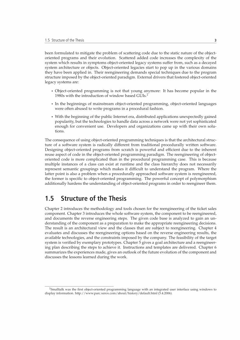
Figure 2.3: Pattern clusters assigned to the reengineering life cycle.
• Detecting Duplicated Code. The patterns aim at detecting duplicated code to reduce main-tenance costs.
• Redistribute Responsibilities. Pure data containers imply navigation code and god classescan cause higher maintenance costs. The patterns suggested can help to mitigate this sort ofproblems.
• Transform Conditionals to Polymorphism. Large conditionals imply couplings betweenclasses. The patterns describe how to eliminate them and thereby improving the flexibilityin future changes.
The ordering of groups of patterns along the reengineering process visualized in the softwarereengineering life cycle form the organizational reengineering framework we are going to applyfor the reengineering of the ticket sales component. It suggests what to do when and to a certaindegree how.
2.4 Refactorings
Patterns that suggest to change the code describe the steps that need to be undertaken generalmanner. The refactorings deliver the details of how changes in the code have to made. Refactoringas defined in Section 2.1 has to be accomplished in a structured way to be successful. Fowler et

2.5 Software Reengineering Tools 11
al. propose a disciplined way to change code that minimizes the chance of introducing bugs in[FBB+99]. It consists of small and simplistic changes to the code to eliminate a bad code smellor to stepwise add code to slowly converge to a target form of the program. The cumulativeeffect of these small changes improve the structure of the program. They propose a collection ofrefactorings for bad code smells and design problems a program can have. For each refactoring, ageneric template is given. The 72 described refactorings can be grouped into the categories givenin Table 2.3.
Category Description ExampleComposing Methods Pack long sections of code into a
method or put code contained ina short method at its place.
Extract method
Moving features betweenobjects
Refactorings to move respon-sibilities at different levels ofgranularity between objects
Move field
Organizing Data The refactorings make workingwith data easier.
Replace record with dataclass
Simplifying ConditionalExpressions
- Replace conditional withpolymorphism
Making Method CallsSimpler
Make methods that representthe interface to an object easierto understand
Rename method
Dealing with Generaliza-tion
Make code more generically us-able
Pull up method
Big Refactorings Often occurring cases that needseveral of the “small” refactor-ings.
Separate domain from pre-sentation
Table 2.3: Overview of refactoring categories.
The analysis of the ticket sales component during reverse engineering will identify the refac-torings we have to make to achieve the reengineering goals. It is essential that testing whetherthe code has been broken goes hand in hand with the refactorings. Automated refactorings (Sec-tion 2.5.5) change the testing policy, but do not substitute it.
2.5 Software Reengineering Tools
The organizational reengineering framework specifies a structure for what to do and when, thequestion how to do it is not considered in detail. The answer is the knowledge of techniques onhow to investigate and change the system. Reengineering tools represent techniques to supportthe investigation and the change of the system.
Tackling with the source code, the hidden architecture of the system, and its problems remainsdifficult and requires a lot of expertise. Reverse engineering tools help to understand the code,derive architectural views and identify design problems by providing software metrics and visu-alizations. The tools offer useful features and ease the reverse engineering work, but they do notmake decisions—neither strategic nor common sense ones.
The output of tool supported software analysis in the reverse engineering phase has twofacets: Metric values and visualizations. Visualizations can be high level UML abstractions ortwo-dimensional drawings illustrating metric information with polymetric views (Section 2.5.2).

12 Chapter 2. Reengineering Methodology
The optimal amount of tool generated information to support the understanding of the programdepends on its complexity and the experience of the programmer. Intensive tool use is dangerousbecause the understanding of the system can become biased by the perspectives the tools offer. Agood approach to minimize this risk is to wait as long as possible with the use of tools.
A considerable amount of reengineering tools with useful features are available to speed upthe reverse engineering process. Some of them come as a set of features integrable in IDEs suchas Eclipse2, others are standalone programs. A lot of them are open source, of academic nature,and the features they offer implement yet young research results from the software reengineeringdomain. As a consequence, the quality of the tools varies a lot. Considering this, and the fact thattools do not solve the actual reengineering problems, they have to be chosen and used selectively.To work efficiently with the once selected tools, it is advisable to first think about what kind ofinformation needs to be gained before starting to work with them. Some of the tools offer a lotof features, but not all of them provide additional relevant information. The IDE used for thisproject is Eclipse 3.1 which comes with built-in refactoring features. The tools considered suitableand chosen to support the given reengineering task are Creole3, Omondo UML4, Java Metrics5,and CodeCrawler.6 All except CodeCrawler are available as Eclipse plug-ins.
2.5.1 Creole for Code Visualization
Creole is an open source Eclipse plug-in that generates visualizations of a code base. It is ableto display class hierarchies, views of source code sets, and their interactions at different granu-larities. For example, Figure 2.4 shows a set of classes. Their interrelation in terms of methodcalls and attribute accesses is expressed with the red arrows. Intra class relations such as meth-ods accessing variables within the classes can also be seen. Creole can be used during the wholereverse engineering phase: To get a quick overview of a code set for the initial understanding ofa software system, in the detailed model capture phase to verify hypotheses about architecture,and to detect bad smells such as too large classes or gravitation classes. Creole runs stable, butuses a lot of memory to generate visualizations.
2.5.2 CodeCrawler for Metrics Visualizations
CodeCrawler is a language independent open source software visualization tool [Lan03]. It isintegrated into the Moose7 reengineering environment which is a language independent envi-ronment for reverse engineering and reengineering software systems. Moose provides a set ofservices including a common meta model, metrics evaluation and visualization, a model repos-itory, generic GUI support for querying, browsing and grouping [NDG05]. The visualizationsCodeCrawler offers are less fancy compared to Creole, but contain more information. The visu-alizations of CodeCrawler are based on polymetric views. A polymetric view can display up tofive metrics (Figure 2.5 a) [Lan04]). We used CodeCrawler in addition to Creole to detect excep-tional entities Creole was not able display, such as the number of methods overridden. A lot ofoverridden methods in extended classes can indicate that the implemented class hierarchy doesnot correspond to a good architecture. CodeCrawler offers a lot of predefined visualizations.Figure 2.5 b) shows one of the class hierarchies of the classes to reengineer. The classes are rep-resented as rectangles, their width is proportional to the number of attributes and their high to
2http://www.eclipse.org3http://www.thechiselgroup.org4http://www.omondo.com5http://metrics.sourceforge.net6http://www.iam.unibe.ch/!scg/Research/CodeCrawler7http://www.iam.unibe.ch/ scg/Research/Moose/

2.5 Software Reengineering Tools 13
Figure 2.4: Creole view of class interactions and intra class variable accesses.
the number of methods they contain. The color represents the sum of lines of code of all methodsthe class contains. The darker the filling, the more lines of code. Such system complexity viewsallow to quickly identify potential design problems (e.g., an unbalanced class hierarchy). Thenames of the classes are not contained in the rectangles. Class names are shown in a text bar inthe Moose environment when the mouse pointer is positioned on an entity. CodeCrawler crasheswhen trying to execute certain operations and the overall program handling is less convenientthan in Creole since the data for the common meta model first needs to be generated. The jFamix8
Eclipse plug-in allows to export the data needed for visualizations in CodeCrawler. The data isexported into a XMI (XML Metadata Interchange) file that can be loaded into CodeCrawler.
Figure 2.5: The principle of a polymetric view (a) and a class hierarchy generated by CodeCrawler using polymetricviews (b).
8http://jfamix.sourceforge.net/eclipse/index.html

14 Chapter 2. Reengineering Methodology
2.5.3 Omondo UML for an Abstract View of the Classes
Omondo UML is an Eclipse plug-in for UML modeling. The software is commercial, but the freeedition comes with enough features for this reengineering project. Reverse engineering of classdiagrams from source code is possible. Synchronization between the class diagram and the Javacode is supported. UML class diagrams are used for redocumentation and to provide templates inthe forward engineering phase. After the changes to the ticket sales component have been made,different types of diagrams will be generated for the technical documentation.
2.5.4 Java Metrics to Collect Relevant Metrics of the System
Java Metrics is an open source Eclipse plug-in that calculates various metrics of Java source codeand includes a dependency analyzer. There are commercial tools9 which can calculate a lot moremetrics than Java Metrics. The metrics computed by Java Metrics are sufficient for this projectsince the goal is to understand the code base and to find design problems rather than to makea quality assurance of the code. The problem with metrics is that it is hard to say starting fromwhich threshold on, or out of which range a metric value is bad. Defining an exceptional valuefor a metric depends on the type of program. For example, classes that build up a GUI inherentlycontain a lot of code to describe all the widget details. The rule of thumb when using metrics forsoftware reengineering is to stick with the simple metrics because complex metrics and ratios ofmetrics tend to give few additional information [DDN03].
Figure 2.6 shows an example of metric results calculated by Java Metrics of all classes subjectto reengineering. A line in the table shows the name of the metric, its aggregated value (total),mean, standard deviation, and maximum values as well as the resource causing the maximumand the method of that resource. A metric can be expanded to see how it is composed on thepackage level (this has been done in Figure 2.6 with the Total Lines of Code metric). The pack-age level can further be expanded to the class level and the class level to the method level. Theresults displayed depend on the entity, the fields are left blank if a metric value is not applicableto an entity (in Figure 2.6 for example, there is no total value for the depth of the inheritance treemeasured over all classes (i.e., on the project level)). The plug-in does not support the creationof customized metric sets, that is the user can not choose which metrics to apply to which set ofclasses. The tool offers an Extensible Markup Language (XML) export feature. As a workaroundto create customized metric sets, the exported raw XML data can be transformed with an Exten-sible Stylesheet Language (XSL) sheet to show customized results in HTML. The Java Metric toolis used to collect the overall metric values of the project and to detect exceptional entities.
2.5.5 Eclipse for Automated Refactorings
Programming languages in which refactoring is not part of the culture often have insufficientrefactoring tool support. This implies that most of the refactoring needs to be done manually. Itprevents programmers from making refactorings because it is seen as a separate task that coststoo much [FBB+99]. The refactoring features in Eclipse integrate programming and refactoringand let refactoring appear as a less separate activity. Eclipse offers a set of automated refactor-ings for Java. The possible refactorings for a marked Java element can be accessed via the contextmenu. Automated refactorings eliminate the possibility of human errors, such as spelling mis-takes. Yet, testing is advisable for technically complex automated refactorings because personaltesting showed that they do not work seamless. Typically, not all references to a modified elementare updated. For example, the automated Push Down Method refactoring does not always update
9For instance the Borland Together product series is able to compute a vast set of metrics for quality assurance(http://www.borland.com/us/products/together).

2.5 Software Reengineering Tools 15
Figure 2.6: Example of metric results calculated by the Java Metrics plug-in.
all the references to the moved method. We will use the Eclipse refactoring features wheneverpossible in conjunction with a testing framework. Automated refactorings improve the produc-tivity. The empirically observed effect on the testing policy is that the frequency of tests runremains the same, but more program changes are verified [FBB+99].


Chapter 3
Reverse Engineering
This chapter documents the core reverse engineering work that has been carried out to gain an un-derstanding of the component to the necessary level of detail for the forward engineering phase.After basic analysis has been terminated, the reengineering priorities will be stated and furthergoal specific analysis work will be carried out.
3.1 Setting Direction
The goal of the reengineering process is a plan including a set of propositions, a number of tem-plates and examples that suggest what changes have to be made in the ticket sales componentto enable its further successful evolution. Before beginning with the analysis, the reengineeringgoals that caused the company to start a reengineering project can already be stated:
• The classes of the component need to be refactored to reduce future maintenance and ex-pansion efforts of the component.
• Adapting the component to be compliant with the current 1.5 JDK.
• Introduction of a new GUI, since the current Java WorkShop1 (JWS) based GUI is brokenfrom a maintenance point of view and does not support the widgets expected from a mod-ern GUI.
With this general goal description at hand, a goal directed reverse engineering process from thebeginning is practicable (i.e., issues to look for when analyzing the artifacts). The hardest partin a software reengineering project is the reverse engineering. Program understanding done theclassical way, that is stepping through the program execution with typical use cases at hand andfollowing the execution path consumes a lot of time. The object-oriented programming paradigmwith the conceptual gap between the static program code and the dynamic runtime behaviorhardens this work additionally. Given a large code base and limited amount of time, the focusat the beginning has to be to quickly verify the feasibility of the reengineering project and thenfind out enough about the software to be able to reengineer it according to the already givenreengineering goals and the ones that will be stated during the reverse engineering process asmore deficiencies of the system might be discovered. The early stage allocation of time slots toreengineering subtasks is difficult because the information about the software and its context isincomplete.
1Java WorkShop was an IDE offered by Sun Microsystems. It was shipped with Abstract Windowing Toolkit (AWT)based classes aiming at easily creating GUIs.

18 Chapter 3. Reverse Engineering
The starting line of this reengineering project is a folder of about 24 Mb of data including Javasource code, class files, batch files, Oracle Forms, a few C files, graphic files, and JWS generatedproject files. What to do first? In which direction has the reengineering effort go at the begin-ning? There are several roads one can start to walk down, but quite a few of them will turn outto be painful deviations or even lead to a point of failure. For example, people involved in theproject can be seduced by technical problems that they are most interested in, instead of focusingon what is the most useful for the reengineering project [DDN03]. The Setting Directions patternsproposed below allow to get a smooth launch and keep important issues in mind from the be-ginning. The problems they refer to are largely of non technical nature and seem simple. Still,not to consider them is negligent. The patterns aim at setting the right path and suggest how tocoordinate and maintain the chosen path. The patterns listed in Table 3.1 demand a project spe-cific answer while those stated in Table 3.2 give facts to keep in mind for the whole project. Thepatterns are condensed to a problem-solution scheme.
Pattern Name Problem SolutionAgree on maxims Establish a common sense of
purpose with the people in-volved.
Establish key priorities of theproject.
Speak to the round table How to keep the involvedpeople synchronized?
Regular communication withthe people involved.
Most valuable fist Which problems to focus onfirst?
Start with the aspects most valu-able to the customer.
If it ain’t broke, don’t fix it Which parts should bereengineered ?
Only fix the broken parts, thosethat can no longer be adapted toplanned changes.
Table 3.1: Overview of the patterns used from the setting directions cluster.
The answers specific to the ticket sales component found trough discussions with the responsibledeveloper considering the problems stated in Table 3.1 are listed below:
• Agree on maxims. The key priorities are to refactor existing logic classes, to make the com-ponent JDK 1.5 compliant, and to propose the implementation of a new GUI.
• Speak to the round table. Emails to the people involved will regularly be sent to reportprogress and get feedback.
• Most valuable first. Work focus is on the GUI component and the classes handling theprecious and complex business logic.
• If it ain’t broke, don’t fix it. The ODP communication fulfills its purpose and is thereforenot a reengineering priority.
3.2 First Contact
After having clarified the direction in which the project has to go, time has come for a closer lookat the ticket sales component. The First Contact patterns suggest to chat with the maintainers andan interview during a demonstration of the software by a user. To validate and expand what hasbeen heard and seen the Read All the Code in One Hour, Skim the Documentation, and Do a MockInstallation patterns from Table 3.3 can be applied.

3.2 First Contact 19
Pattern Name Problem SolutionFix problems, not symp-toms
How to tackle all the re-ported problems ?
The source of the problem needsto be addressed, rather thanstakeholder specific interests.
Keep it simple How much flexibility shouldbe built into the new system?
An adequate, but simple solu-tion should be preferred to amore general, complex one.
Table 3.2: Setting direction patterns stating generic rules to keep in mind during the reengineering project.
Pattern Name Problem SolutionChat with the maintainers How to get a good perspec-
tive on the historical and po-litical context of the legacysystem?
Discuss the problems with themaintainers.
Interview during demo How to get an idea of typicaluse cases and the main fea-tures of the system?
Observe the system in operationby seeing a demo and interview-ing the person who is demon-strating.
Read all the code in onehour
How to get a first impressionof the quality of the sourcecode?
A short, but intense time tostudy the code.
Skim the documentation How to identify the partsof the documentation thatmight be of help?
Preparation of a list summariz-ing the important aspects forthe reengineering project. Then,matching of that list against thedocumentation and meanwhilemake an assessment of how upto date the documentation is.
Do a mock installation How to be sure to be able torebuild the system?
Build and install the system in aclean environment during a lim-ited amount of time.
Table 3.3: First Contact patterns used to get to know the system.
The difficulty in this phase of the project is being faced with a software that is not understood atall and being forced to make substantial decisions on how to proceed in detail [DDN03]. One alsohas to be aware that the first impression can mislead. To minimize that risk, the hypotheses aboutthe source code always have to be verified. The following sections summarize what we learnedabout the component applying the patterns in Table 3.3 while interviewing users working withthe ticket sales client, chatting with the developer who is at the same time maintainer of thecomponent and our own first look at the system and its components.
3.2.1 Interview during Demo
The goal of interviewing is to get an idea of typical use cases, the main features of the softwaresystem, and to learn about problems the users may experience when using the software. An in-terview was conducted with a person responsible for the deployment of the whole event manage-ment software at client sites. The ticket sales component demonstration aimed at getting familiar

20 Chapter 3. Reverse Engineering
with the main features. Figure 3.1 shows the main working surface of the ticket sales compo-nent. A hall map of an event is loaded where the user can select seats for reservation or sale. Thefollowing technical facts were be extracted from the interview:
Figure 3.1: GUI of the main working surface of the ticket sales component.
• The ticket sales component uses sockets for communication with the an application server.
• The version management software used is Source Safe
• The tickets are printed out with a bar code for identification and cancellation.
The identified features are:
• Lockup events and show the state of the available seats
• Selling or reservation of seats for events
• Change or add new customer information to the customer base
• Choice between cash, billing or electronic payment is possible
• When the hall map of an event is very large, it is possible to only load segments of it. Thisis useful to relieve the database and to have a better overview

3.2 First Contact 21
• Batch printing of tickets at the end of the day in the call center
• Management of different types of subscriptions
• Selling of merchandise articles
• Ticket selling of events without seats or unnumbered seats
• Automatic calculation of discounts
The features listed represent the main functionality. More functionality is available due to thecomplicated sales policies common in the cultural event sector. Additionally, short interviewswere conducted with users of the ticket sales component. The users seemed comfortable with thesystem. They used it efficiently and knew workarounds for minor problems they faced duringoperation. The most common use cases are over the counter ticket sales at the point of sale andticket reservations and selling in a call center which is implemented considering a customer baseto identify the customer. The standard procedure to buy a ticket at a sales point is as follows:
1. Search an event with constraints given by the customer, for example searching by date ortitle of the event
2. Click on free seat(s) in the displayed hall map or enter the number of tickets to be sold incase of an event having non numerated seats or no seats at all (e.g., a museum visit).
3. Click on the sales button to proceed to the payment method. The user has the possibility toenter a new customer or to search an already existing one in the database to associate thetransaction with a customer.
4. After successful payment, the amount of tickets bought will be printed out on a ticketprinter.
The information collected in the interviews while the ticket sales component was running gave arough functional view. Next, the Chat with the Maintainers pattern can be applied to learn moreabout the underlying technical mechanisms of the described functionality.
3.2.2 Chat with the Maintainers
The discussions we had with the maintainer about the whole cultural event management systemand the ticket sales component as a part of it are documented in the next two sections.
A Software System to Manage Cultural Events
The software system for managing cultural events consists of six components. The system offersfunctionalities to register an event such as a theater piece in a database, ticket selling thereof, andreporting about the stored data, for example how often an event was frequented during a certaintime period. The database stores all the information necessary relating to an event and a customerbase. Figure 3.2 gives an architectural overview of the system. The components of the eventmanagement system are centered around a database. They use different forms of communicationfor historical reasons. The database is also accessed by other IT systems, for example accountingapplications.
• The hall map editor client is an Java client to add new plans of event locations to the data-base via the application server.

22 Chapter 3. Reverse Engineering
• The administration tool is an Oracle Forms2 application that offers report generating func-tionalities for the back office.
• The application server is a Java application that interconnects the ticket sales and hall mapeditor clients to the database.
• The ticket sales client is a Java application to manage the over the counter and call centerticket sales processes. The offered functionalities are ticket reservations, ticket exchange,ticket selling and customer base management.
• The Web ticket sales component is a Java applet to integrate ticket reservation and sellinginto a Web page.
• The Web server is a Java application that interconnects the Web ticket sales component tothe database.
Figure 3.2: Component view of the event managing system.
The hall map editor and the ticket sales client use an ODP3 based protocol for communicationwith the application server. Communication between the application server and the database aswell as between the administration tool and the database is done with SQLNet.4 The Web ticketsales component communicates via HTML with the Web server and the Web server uses JDBC5
to interact with the database.The four client components can be run independently from each other. Several instantiations
of one application can run concurrently. The software has been gradually developed and intro-duced starting from 1992 on at the Bundestheater in Vienna. Today the whole system is oper-ational at different customers in the cultural domain. Customers are typically ticket sales orga-
2Oracle Forms is a rapid application development environment for developing database applications. The languageused inside is PL/SQL. PL/SQL (Procedural Language/Structured Query Language) is a proprietary server-based proce-dural extension to the SQL database language from Oracle. http://en.wikipedia.org/wiki/Oracle Forms (3.2.2006).
3Open Distributed Processing (ODP) is a standard proposed in 1992 by ISO with the aim to establish a commonreference model to develop distributed applications in open, heterogeneous system environments. http://www.rm-odp.net/index.html#standards (6.4.2006).
4SQLNet is the client/server middleware product from Oracle that offers transparent connection from client tools tothe database, or from one database to another. http://www.orafaq.com/faqnet.htm#WHAT (6.4.2006).
5Java Database Connectivity (JDBC) is an API for the Java programming language that defines how a client mayaccess a database. It provides methods for querying and updating data in a database. JDBC is oriented toward relationaldatabases. http://en.wikipedia.org/wiki/JDBC (5.4.2006).

3.2 First Contact 23
nizations acting on behalf of theaters, opera houses, and museums. The ticket sales client is thecomponent to be reengineered.
The Ticket Sales Component
The ticket sales program was originally implemented with Oracle Forms in 1993. When the re-quirement to implement dynamic hall maps arose, the Oracle Forms environment came to itslimits. In a dynamic hall map, attributes of seats such as price category or marking for disabledpersons can change for each event the hall map is assigned to. Whereas in a static hall map, theonce entered seat attributes configuration was not changeable anymore after it had been defined.Dynamic hall maps were the driver for a new implementation of the ticket sales client. In 1996,the company decided to develop a new GUI for the business processes needed at sales points. TheGUI was implemented in Java using the JWS WYSIWYG editor. To handle server communication,an ODP based protocol using sockets was developed in Java by the company. This has been donebecause Java RMI (Remote Method Invocation) was just about to come out, not yet well known,and the company already had considerable knowledge about ODP. The purpose of the ticket salescomponent classes is either GUI related or ODP communication related. The work invested forthe first productive release is about two man-years.
Since its introduction, the component has undergone a lot of changes and the JWS classesare no longer supported by Sun Microsystems. Changes to the GUI classes cannot be made viaWYSIWYG editor anymore due to memory problems. Today, the component still runs with theoriginally used JDK 1.1.8 because changes made by Sun Microsystems in the AWT classes of laterJDK versions where incompatible with the JWS classes. The business logic has grown large in anuncontrolled manner with the numerous changes that have been made over the years and is hardto maintain.
The ticket sales component class files are delivered to customers together with the hall mapeditor class files and the application server class files in a ZIP-file called inhouse.zip. Figure 3.3shows that the client and the server side use different files from the same ZIP-file. All files having‘‘form cl’’ and ‘‘map cl’’ in the beginning of their names are deployed on the client sideand all files starting with ‘‘data sv’’ are deployed on the server side. Files implementing theODP protocol are used on client and server side.The server then redirects the traffic to a databasestub using JNI.6 The database stub contains configurations files used by the SQLNet middlewareto connect to the database.
A user manual for the ticket sales component exists, but is outdated. Component testingis done with statements embedded in methods generating runtime data and writing it on theconsole and in log files. The statements can be activated via a parameters given at startup. Theticket sales component maintainer was also the main developer of the component. When therequirement for ticket sales via the Internet came up, a separate component was created, whichalso shows dynamic hall maps in an Java applet the customer can choose a seat from, buy itelectronically, and print it out at home. Authenticity of Web-tickets is assured with a bar code.
3.2.3 Skim the Documentation
The purpose of this pattern is to assess the relevance of the available ticket sales component doc-umentation. The technical documentation is limited to a couple of descriptions of how to set upthe ticket sales component at client sites. A detailed 84 pages user manual describing the featuresof the ticket sales component exists, but is outdated. Recently added features are not mentioned
6The Java Native Interface (JNI) is a programming framework that allows Java code running in the Java virtual ma-chine to call and be called by native applications and libraries written in other languages, such as C, C++, and assembly.http://en.wikipedia.org/wiki/JNI (5.4.2006).

24 Chapter 3. Reverse Engineering
Figure 3.3: Communication path of the ticket sales component with the database.
and the GUI layout looks different today as shown in the manual. Although, browsing the man-ual was useful for a better understanding of a number of the features available in the ticket salessystem. The existing documentation is not a key to technically understand the ticket sales com-ponent.
3.2.4 Read All the Code in One Hour
The intent of this pattern is to get a first impression of the quality of the source code. The patternname suggests to only browse the code without studying details. In preparation for that, thesource code and the necessary JAR (Java Archive) files had been loaded into Eclipse. Our goalswere to find out which classes are used by the ticket sales component (since classes for the server,the hall map editor and the ticket sales component came together in one zipped package), tounderstand the purpose of the packages, try to identify potentially problematic classes, and tolook for comments in the classes describing their functionality.
The set of classes having their name beginning with form cl is responsible for the instantia-tion of the whole GUI panel. The three packages identified to be part of the ticket sales componentare used by most of the classes of the form cl set.
• The group package contains about 70 classes responsible for the creation of sub-panels inthe main GUI for the ticket sales component. A part of the group-package classes wereautomatically generated by the JWS environment.
• The odp package contains about 30 classes that handle the communication between theticket sales component and the application server. Most of the classes in this package aremembers of a hierarchy. The root class of this hierarchy is odp. It contains the abstract meth-ods send(DataOutputStream stream) and recv(DataInputStream stream)whichboth return an integer value and are responsible for the transfer of data between the client(s)and the server.
• The three Java classes in the data are either needed for ticket printing or only used on theserver side.
The class form clCache is about 9000 lines long. It handles the GUI controll logic and calls thedatabase with ODP methods. A part of the classes are not commented at all, others are com-mented in detail. Additionally, we created a Javadoc to get a feeling of the overall commentingused in all the classes. The jws.zip archive contains the JWS GUI class files. The classes.zipfile contains the JRE 1.1.8 delivered with the ticket sales component ZIP-file. we also took a brief

3.3 Initial Understanding 25
look at the Bugzilla7 software management system used by the company. The Bug activity relatedto the ticket sales component was about equally weighted between feature and bug requests.form clCache) is the hot spot in the ticket sales component.
3.2.5 Do a Mock Installation
Doing a successful mock installation ensures that all the code necessary for the reengineeringis available and gives the possibility to test the features with a non productive instance of thesoftware. In preparation for that, the person responsible of the database resort in the companyalready set up a test database on a mobile hard drive and the server part on our workstation.Classes drawn from SourceSafe8 have been added to the Eclipse Project until all class depen-dencies were resolved. as a last step, the correct program startup parameters and compile optionshad to be passed over to the compiler. we took the outdated user manual and tested the describedfeatures to further get acquainted to the ticket sales component.
3.2.6 Summary of the First Contact
The ticket sales component has an old fashioned GUI offering a lot of functionality to the user.Communication with the server is done with an inhouse-made class hierarchy implementing theODP protocol. Large sections of code are not documented at all. The user manual is outdated. Thesystem is operational, but hard to maintain and enhance. A mock install was successful indicatingthat the necessary code base is complete. Bugzilla shows an equal weight between bug reportingand feature requests. The GUI widget classes are automatically generated by the JWS WYSIWYGeditor and a number of the GUI controller classes have grown to god classes. The focus whenapplying as a next step the Initial understanding pattern set will be on the understanding of theclasses containing a large number of code. The so far acquired knowledge about the ticket salescomponent is not sufficient enough yet to refine the reengineering goals already stated at thebeginning of Section 3.1. Nevertheless, the reengineering project is feasible because no significantartifacts are missing and the people who where involved in the development of the ticket salesmodule are still with the company.
3.3 Initial Understanding
The First Contact patterns allowed to get familiar with the general set-up of the system as well as arough identification of its structure and of problem zones in the code. The more detailed design ofthe ticket sales component is not yet understood and it is unknown how big the effort is going tobe acquire an understanding as base for reengineering decisions. The Initial understanding patternset allows to refine the discoveries made in the First Contact pattern set. Table 3.4 summarizes thetwo patterns applied to the component. The Speculate about Design pattern represents a top-downanalysis approach whereas the Study the Exceptional Entities pattern incorporates a bottom-upapproach.
7http://www.bugzilla.org8Microsoft Visual SourceSafe is a source control software package oriented toward smaller software development
projects. http://en.wikipedia.org/wiki/Sourcesafe (7.4.2006).

26 Chapter 3. Reverse Engineering
Pattern Name Problem SolutionSpeculate about Design How to recover the way
design concepts are repre-sented in the source code?
Appliance of development ex-pertise to conceive a hypothet-ical class diagram representingthe design.
Study the Exceptional En-tities
How to quickly identify po-tential design problems inlarge software systems?
Measurements of structural en-tities forming the system andidentification of exceptions inthe collected quantitative data.
Table 3.4: Initial Understanding patterns used to discover the details of the ticket sales component.
3.3.1 Speculate about Design
Manually drawing an initial hypothetical class diagram and to refine it through browsing thecode of a component consisting of approximately 200 classes with an insufficient understandingof the system even to formulate hypotheses is useless. Instead, we decided to generate UMLdiagrams of potentially interesting sets of classes of the component. A small example of a classdiagram is given in Figure 3.4. This allowed to quickly see the number of methods and attributesclasses have as well as how classes are related to each other. We then formulated the questionslisted beneath. The goal of this modified pattern is therefore to find answers to those designrelated questions. The knowledge gained in answering those questions will allow to create auseful initial architectural view in which classes are grouped depending on their purpose.
Figure 3.4: An UML class diagram showing inheritance relations.
• Which classes are used by the ticket sales component?
• How is the JWS event handling mechanism embedded in the code?
• How is the hierarchical structure of the classes?
• Can all the classes be grouped in sets depending on their purpose?
Ticket Sales Component Classes
The editor, server, and ticket sales classes are not kept separate from each other. There is little JWSclass documentation available. As a first step, to create a better overview of the project, classes

3.3 Initial Understanding 27
have been iteratively removed from the Eclipse project because their name suggested that theydo not belong to the ticket sales component. We recompiled the ticket sales component to verifythat the removed classes are not needed. If there are more classes that are not part of the ticketsales component, they will definitively be identified later when stepping through the executionto relate features to code. The classes listed in Table 3.5 are the only ones left that are not in apackage. We call them loose classes from now on. A closer look allowed to identify their purpose.The “Type” column in Table 3.5 refers to whether the class has been automatically generated bythe JWS WYSIWYG editor, partially automatically generated as a template (to wire user inputactions with handwritten classes or to overwrite them to have specific actions implemented) tobe filled up by the programmer, or are handwritten.
Name Type Purposeform clMain automatically generated Contains the main method. Instanti-
ates form cl.form cl template Instantiates form clRoot and
form clCache. “Relay” class tak-ing events from form clOps anddelegating them to form clCache.
form clCache handwritten Communication god class between theGUI and the application server.
form clRoot automatically generated All the GUI widgets are defined in thisclass.
form clOps automatically generated The GUI elements that need to reactto user input are registered in a vec-tor. A case statement delegates the GUIevents.
KartendruckCache handwritten Needed by KartendruckThread.KartendruckThread handwritten A thread class to print tickets, instanti-
ated in form clCache.
Table 3.5: Overview of loose classes.
The classes named with ‘‘form cl’’ are the center of the component: They start the com-ponent, are in charge of assembling the GUI, handle client side logic, and communicate with theserver by instantiating ODP classes. The three packages (data, group and odp) are corded to bedeployed by the ‘‘form cl’’ classes.
JWS Knowledge
We decided to learn more about the JWS API9. A series of questions concerned with the JWS ter-minology and the JWS class model showed up when we looked at classes generated with JavaWorkshop. The JWS Knowledge stated here helps to better understand the code, the design de-cisions that were forced by using JWS, and to verify the stated propositions of the purpose ofclasses investigated in the last section. The JWS GUI builder introduces two new terms: groupand shadow. Shadows are wrapper classes for an AWT components. They hide the event modeland AWT classes behind an extra layer of code. They propagate AWT events to groups. A groupis a container to bundle a set of GUI elements. It can contain shadows and other groups. Groups
9Useful JWS documentation was not findable on the website of Sun Microsystems anymore.http://www.dimi.uniud.it/labs/ documentazione/jws2.0-help/jws/visual/generate.html (15.3.2006) gives an overviewto JWS.

28 Chapter 3. Reverse Engineering
that are included inside other groups are called subgroups. The JWS GUI builder is used to createnew groups out of existing shadows and groups. New groups must be subclasses of the JWSGroup class. The top-level group is called the base group. A tree of groups exists while the appli-cation is running. Messages sent by subgroups propagate up toward the top of the tree until theyare handled or they reach the base group.
A group is accessed via a set of attributes and methods that the Group class defines. Subclassesof the Group class add their own customized attributes and methods. Applications created us-ing the JWS GUI builder are groups. A large application typically consists of a base group thatcontains a lot of other shadows and subgroups. Each group represents a project in JWS. The JWSproject manager allows to integrate projects, that is GUI components are added to a main GUI. AJava WorkShop project can contain only one group, but projects can contain other projects.
When the code of a group is generated with the Java WorkShop application based on thedesigned WYSIWYG layout, the following files result in the source directory of the project:
• example.gui contains the code that describes the GUI for Java Workshop based errorchecking. This file is not important since Java Workshop will no longer be used.
• exampleRoot.java contains the code necessary to initialize the components for the group.This file is recreated every time a GUI is built.
• exampleOps.java contains the operations for the group. This file is generated only if op-erations have been defined on one or more of the components in the corresponding group.This file is recreated every time a GUI is built.
• exampleMain.java contains the main method that is used to run the group as an appletor a standalone application. This file is recreated every time a GUI is built.
• example.java contains a template for the group. This file is generated only once. This filecan be modified to implement event handlers, action handlers, and other functionality.
The JWS imposed class structure clarifies the purpose of most of the form cl-named classesdiscussed in Table 3.5 and of the GUI classes in the group package. The group package furthercontains interface classes which will be examined with the Look for the Contracts pattern in Sec-tion 3.5.2. The identification of sets of classes that represent GUI components is usable as an ar-chitectural view of the GUI part of the ticket sales component. This structure can help to composethe GUI renewing task into steps in the forward engineering phase.
JWS Event Handling
The used JWS (version 2.0) API is based on Java SDK 1.0 AWT classes. “The model for eventprocessing in version 1.0 of the AWT is based on inheritance. In order for a program to catchand process GUI events, it must subclass GUI components and override either action() orhandleEvent() methods. Returning true from one of these methods consumes the event soit is not processed further; otherwise the event is propagated sequentially up the GUI hierarchyuntil either it is consumed or the root of the hierarchy is reached.”10 Since SDK 1.1, the eventhandling model has become delegation-based (i.e., an event is propagated from an originatingobject to a “Listener” object by invoking a method on the listener and passing an instance of theevent.).
The form clOps class contains a registration vector for GUI elements. When an event fromthe GUI arrives, the overridden method handleMessage(Message msg) is automatically no-tified. This class has been taken as a starting point to validate how user input is handled in the
10Java AWT: Delegation Event Model, http://java.sun.com/j2se/1.3/docs/guide/awt/designspec/events.html(19.4.2006).
3.3 Initial Understanding 29
ticket sales component (i.e., which methods are called and how the information is prepared forthe ODP communication). This allows to verify the assumed SDK 1.0 AWT based JWS eventmodel and to see which classes are involved in often occurring user operations. Following themethod calls has been done statically since the JDK 1.1.8 needed to run JWS is not compliant withthe Eclipse debugger front-end. As a remedy to this, the feature Eclipse offers to show all thereferences of a highlighted method name in the workspace has been used. The result of staticallyfollowing the execution string is shown in Figure 3.5.
form_clOps.handleMessage(Message msg)
form_clOps.private void handleCallback(int index, Message msg, event evt)
form_cl.cacheAction(String sSubMethodTyp, Event evt)
form_clCache.method(String sSubMethodTyp, Event evt)Starts ODP Object Transfer
GUI User Input
Figure 3.5: Typical method call path for handling GUI user input events that trigger database access.
In the form clOps class, handleMessage(Message msg) calls handleCallback (intindex, Message msg, Event evt) where Message is a public JWS class derived from Ob-ject that represents an event structure that can hold either an AWT event or a specialized eventpassed between instances of type Group. The method handleCallback(int index,Messagemsg, Event evt) contains a case statement that offers a choice of between 108 options based onthe vector index integer determined in handleMessage( Message msg). Each case calls themethod cacheAction( String sSubMethodTyp,Event evt) in the form cl class with adifferent string. cacheAction( String sSubMethodTyp,Event evt) then calls method(sSubMethodTyp, evt) in the form clCache class. The form cl class is used for navigationtoward the form clCache class that controls the GUI and communicates with the server. Themethod( String sSubMethodTyp,Event evt) method in form clCache contains about1000 lines of conditional code to decide which methods—mostly in the same class—have to becalled based on the event. The form cl class actually foreseen as a controller class, but the eventsfrom the GUI are delegated to be handled in the form clCache which is an ODP class and hascapabilities for communication with the database.
The Hierarchical Structure of the Classes
Visualizations of class hierarchies are useful for the understanding of a program and to spot de-sign problems. Caution is advised when class hierarchies are used for design recovery becausea design can be implemented in various ways. The hierarchical structure of the odp package isshown in Figure 3.6. The classes in the subtree on the left represent class types that can be used forcommunication with the server. The subtree having as the root the OdpUnit class represent com-munication types used by the classes responsible for loading and drawing hall maps. MethodOdpis a superclass of the form clCache logic god class and implements client-server communicationmethods. OdpArray holds basic ODP types for data transfer. OdpColor holds class constantsdefining the colors used in hall maps. 26 of total 31 classes in the odp package are contained in thehierarchy. One of the remaining five classes is an interface to the class SQL in the data package.

30 Chapter 3. Reverse Engineering
The other four are concerned with threading or ODP object management. The root class odp con-tains two abstract methods public abstract int send( DataOutputStream stream )and public abstract int recv( DataInputStream stream ) that each non-abstract subclass needs to im-plement.
Figure 3.6: Hierarchy of classes in the odp package.
Figure 3.7 shows the classes that are members of hierarchical orderings in the group package.A majority of the classes in the group package obey to the JWS driven design pattern intro-duced in Section 3.3.1. The classes (of type example.java, which is a subclass of Group) inthe hierarchy are ordered to represent specializations of groups, the classes representing leavenodes of the tree imply the generation of an exampleRoot and an exampleMain class. A classof type exampleOps is not always generated. Instead, events are directly caught in the Groupsubclasses. The classes of type Group in the group package not shown in Figure 3.7 are directsubclasses of JWS classes. Creole does not show them since it is only able create visualizations ofsource code classes and not class files.
MVC Perspective
The model-view-controller (MVC) design pattern is a must contract in software systems includingcomplex GUIs. Its interpretation depends on the level of granularity (i.e., at the widget level orcomponent level). We consider the component level. We want to verify whether all the classescan be assigned to either the model, the view, or the controller. If this is possible, the work inthe forward engineering can be done per layer. If not, the separation of concerns also has to beconsidered.
View classes are automatically generated subclasses of type Root. The controller classes areautomatically generated subclasses of the class Operations. The controller listens to events inthe view classes and handles them by calling corresponding methods in the subclasses of theGroup class or in the form clCache class. The custom classes derived from the Group class areas well controller classes. They access Root classes of their group and call the form clCacheclass to invoke methods that globally affect the GUI (e.g., to access the database). The custom

3.3 Initial Understanding 31
Figure 3.7: The class hierarchies of the group package.
Group classes also contain business logic related to the GUI component they represent, for exam-ple the validation if GUI input data corresponds to a given format). The ClientCache and theform clCache classes contain global variables of the application model, communication logic,and access the view. They contain controller and model characteristics. The custom groups inform clRoot use their own Operations classes to handle events of the custom group. If thecase of local events, they call methods of their group and in case of global events, they accessform clCache via interfaces. The classes the JWS editor creates follow the MVC pattern, exceptfor the ClientCache and form clCache classes. Figure 3.8 gives a top level visualization ofthe considerations made.
Note: form clCache contains communication logic, business logic, and GUI controll logic. Ifonly logic is written, we refer to all three types of logic in the controller (which includesform clCache. Each JWS group has a controller class which only contains business and GUIcontroll logic and no communication logic because the JWS group controller class do not havecommunication abilities. If they have to access the database due to an event handled locally inthe group, they use interface types which reference form clCache.
Combining the identified JWS driven architectural structure, the understanding of the eventhandling mechanism, and the MVC concept, it is now possible to clearly assign the majority ofthe classes to one of the three layers. This rough grouping is a base for a reengineering plan. Viewclasses can be amputated and substituted with new GUI classes, the global controller classes canbe refactored, code of the local controller classes (i.e., of subtype Group can be partially reused,and the ODP classes that represent communication types can be left aside.

32 Chapter 3. Reverse Engineering
Figure 3.8: Assignment of classes to model, view, or control layer.
3.3.2 Study the Exceptional Entities
The Speculate about Design pattern approached the code top-down with questions that had to beanswered to gain insight to the architecture of the component. Studying the exceptional entitiesapproaches the code bottom-up examining it from a metric perspective. This allows to refine thearchitectural view and to spot potential design problems indicated by abnormal metrics. There isalways a human assessment necessary to verify whether the metric value truly indicates a designproblem. The difficulty with using metrics is to define when a metric value is exceptional. Thisdepends on the type of program and from the notion the examiner has of program design prac-tices. The available metric tools offer a great variety of metrics. Many of the “high-end metrics”do not bring much additional information gain for our purposes. We will therefore perform theanalysis with a set of simple metrics. Metrics can also deliver useful information for the qualityassurance of a software system. They can be used to rate the code changes during the reengi-neering and afterward during regular maintenance cycles. The Java Metrics tool (Section 2.5.4) isused to generate metric values from the code and CodeCrawler (Section 2.5.2) to visualize them.The metrics used to analyze the beneath listed structural entities are explained as they are used.The metric acronyms vary in the literature. The acronyms in this thesis have been chosen to bestrepresent their meaning in the context of the entity considered. The threshold values of the met-rics have been chosen that they are exceptional in the context of the whole project. This producesgood results because the component has a lot of classes with normal metric values and a few withextremely exceptional values.
• Metrics on package level give an overall impression of the program part under investiga-tion.
• Class size metrics deliver information of how it looks inside classes.
• Metrics relating to the class inheritance highlight anomalies in the class hierarchy whichare often coupled with architectural deficiencies.
• Method metrics allow to spot bad method smells such as too much control.

3.3 Initial Understanding 33
Package Level Metrics
The whole project has 17 packages and a total of 36,841 lines of code. Table 3.6 shows the usedpackage level metrics. Table 3.7 lists the lines of code and the number of classes a package con-tains.
Metric Acronym Full Name CommentLOCP Lines of code per package Without blank lines and com-
mentsNOC Number of classes -
Table 3.6: Abbreviation and full description of the metrics used on the package level.
Package LOCP NOCloose classes 13866 9group 10445 60data 192 3odp 4154 31com.culturall.bankomatkasse.rmi 1618 25com.culturall.bankomatkasse.message.response 1175 12com.culturall.bankomatkasse.message.request 379 9com.culturall.bankomatkasse.protocol 362 7com.culturall.bankomatkasse.message 168 5com.culturall.bankomatkasse.debug 126 3com.culturall.javax.pay 592 5com.culturall.terminal 262 4com.culturall.magnetkartenleser.modelle 205 3com.culturall.magnetkartenleser 438 2com.culturall.util 171 3com.culturall.printspooler 1715 16com.culturall.administration 973 7
Table 3.7: List of metric values on package level.
The packages mentioned alongside the already known ones (group, data, odp, and the looseclasses) in Table 3.7 are needed to resolve import dependencies imposed by the classes in thepackages given to reengineer. Most of them have been added to the ticket sales component tokeep up with the time enabling electronic payment functionality. The metric results for thoseclasses are all normal and browsing through the code convinced us that they are well structuredand documented sufficiently. They are therefore not considered further for the reengineeringand it is supposed that they will be imported if necessary into the code to be restructured. Theywill only be reconsidered if a major design deficiency relating to them would show up whenapplying the Detailed Model Capture patterns. Table 3.7 shows that there are nine loose classeswith 13’866 lines—few classes with a great number of lines of code. The metrics for the data andodp packages are normal. A look inside the group, data, and odp packages shows that no classhas more than 1000 lines of code (LOC) which we consider as an alert value.

34 Chapter 3. Reverse Engineering
Class Size Metrics
The whole project consists of 204 classes. Only the ones violating one of the constraints definedfor the chosen metrics in Table 3.8 are be shown. The bold values in Table 3.9 indicate a metricconstraint violation. The classes in Table 3.9 have to be manually evaluated to assess whether theexceptional metric value(s) truly indicate a design problem. The listing in Table 3.10 shows thepurpose and an assessing commentary of the manually investigated classes.
Acronym Full Name Threshold CommentLOCC Lines of code
per class500 Lines of code without blank lines and comments.
Automatically generated GUI classes can have alot more LOC and do not pose a design problem(if managed with an editor).
NOM Number ofmethods
30 Big values indicate too much functionality. Staticand abstract methods are included.
NORM Number ofoverriddenmethods
5 Methods in GUI API frameworks are often over-ridden to implement event handling or customiz-ing GUI elements. Abstract inherited methods arenot counted.11
NOF Number offields12
50 Does not include static fields. Indicates a data con-tainer smell.
NSF Number ofstatic fields
50 indicates where commonly used information is lo-cated.
Table 3.8: Abbreviation, full description, and threshold values of the used class size metrics.
11The ticket sales component has 213 abstract inherited methods. A lot of them are due to the abstractness of JWSclasses.
12A field is also called attribute.13Abstract inherited methods and methods invoking super are not counted. Overwriting of the methods toString,
hashCode, and equals are not counted.

3.3 Initial Understanding 35
Class LOCC NOM NORM13 NOF NSFloose classesform clCache 7067 160 2 116 8form clRoot 4594 2 0 470 0form clOps 1479 6 1 3 0form cl 321 19 9 7 1group classesMapEditVJCanvas 700 21 4 31 5MultiColListGroup 694 34 2 12 0EditListGroup 642 34 4 7 0KeyListGroup 480 35 4 11 3VorstListGroup 248 30 1 33 0ShortKeyListGroup 240 22 9 3 0odp classesClientCache 898 41 0 66 60ObjectOdp 530 30 1 16 12MethodOdp 191 30 0 12 2OdpELSPlace 224 13 6 12 22OdpColor 282 8 0 1 73
Table 3.9: Classes with exceptional metric values.
Class Purpose Assessmentloose classesform clCache Communication class between
GUI and application serverContains a lot of logic andhas to be split up. The centerof the refactoring work!
form clRoot GUI creation Contains widgets that needto be considered in thereengineering to conservefamiliarity. Will be replacedby the new GUI.
form clOps Stores event sensitive GUI wid-gets in a vector and delegatesthe events to the form cl class.
It will be important for thedevelopment of a refactoringstrategy since it indicates therelations between operationsand GUI elements.
form cl The top-level group. Delegatesevents to form clCache.
Contains a set of default pa-rameters that need to be con-sidered in the reengineering.Will be replaced by the newGUI.
continued on next page
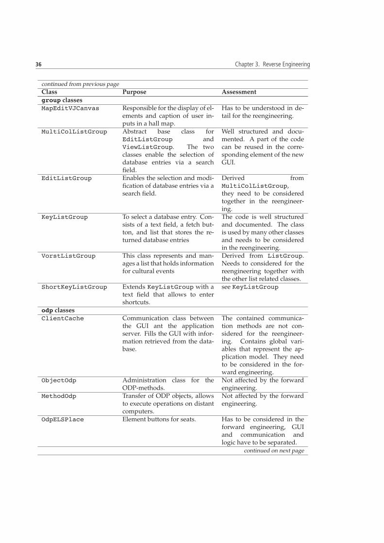
36 Chapter 3. Reverse Engineering
continued from previous page
Class Purpose Assessmentgroup classesMapEditVJCanvas Responsible for the display of el-
ements and caption of user in-puts in a hall map.
Has to be understood in de-tail for the reengineering.
MultiColListGroup Abstract base class forEditListGroup andViewListGroup. The twoclasses enable the selection ofdatabase entries via a searchfield.
Well structured and docu-mented. A part of the codecan be reused in the corre-sponding element of the newGUI.
EditListGroup Enables the selection and modi-fication of database entries via asearch field.
Derived fromMultiColListGroup,they need to be consideredtogether in the reengineer-ing.
KeyListGroup To select a database entry. Con-sists of a text field, a fetch but-ton, and list that stores the re-turned database entries
The code is well structuredand documented. The classis used by many other classesand needs to be consideredin the reengineering.
VorstListGroup This class represents and man-ages a list that holds informationfor cultural events
Derived from ListGroup.Needs to considered for thereengineering together withthe other list related classes.
ShortKeyListGroup Extends KeyListGroup with atext field that allows to entershortcuts.
see KeyListGroup
odp classesClientCache Communication class between
the GUI ant the applicationserver. Fills the GUI with infor-mation retrieved from the data-base.
The contained communica-tion methods are not con-sidered for the reengineer-ing. Contains global vari-ables that represent the ap-plication model. They needto be considered in the for-ward engineering.
ObjectOdp Administration class for theODP-methods.
Not affected by the forwardengineering.
MethodOdp Transfer of ODP objects, allowsto execute operations on distantcomputers.
Not affected by the forwardengineering.
OdpELSPlace Element buttons for seats. Has to be considered in theforward engineering, GUIand communication andlogic have to be separated.
continued on next page

3.3 Initial Understanding 37
continued from previous page
Class Purpose AssessmentOdpColor Defines colors for custom paint-
ing of the canvasContains 73 static attributesthat define colors. Theyare accessed by methods thatpaint elements of the GUI.This class is a data container.
Table 3.10: Manual evaluation summary of classes identified to have exceptional class size metrics.
The metric values for form clCache further underline the god class smell. The form clRootclass is automatically generated and contains the GUI widgets. The constraint violations are there-fore reasonable. The group classes create and controll elements of the main GUI, handle events,and invoke ODP communication with the application server. The ClientCache class in the odppackage is responsible for handling the communication mainly coming from form clCachewiththe application server. It has similar functionality for the main GUI component than the classescontaining ‘‘group’’ in their name in the group package. It is not surprising to see that theodp classes tend to have a lot of methods since they are responsible for communication (e.g., loadin a vector for communication).
Class Inheritance Metrics
The class size metrics allowed to spot several classes with unusual metrics in the ticket sales classset. Keeping those selected classes in mind, it is interesting to see where they are located in theclass hierarchy. The class inheritance metrics in combination with visualizations generated byCodeCrawler of the inheritance hierarchies allow to learn about the hierarchical context they aresituated in. Table 3.11 shows the metrics chosen to use. Table 3.12 shows the collected results. TheOdpValue is the base class for all ODP data types. The group classes with high DIT values arespecialized custom classes. Class inheritance metrics are useful to identify exceptional parts in aclass hierarchy, but they are not informative to obtain an understanding of the system because asystem architecture can be implemented in various ways via a class hierarchy.
MetricAcronym
Full Name Threshold Comment
NSC Number of subclasses 5 direct subclasses are counted.DIT Depth of inheritance tree 6 path length from root to referred
class.
Table 3.11: Abbreviation and full description used class inheritance metrics.
Method Metrics
The metrics chosen to investigate the code on the method level are explained in Table 3.13.The values in the “Method” column in Table 3.14 are given in the ‘‘class.method’’ for-
mat.The form clRoot.form clRoot(Group group) method initializes the main GUI compo-
nent with one method. The form clOps.initializeOps() method registers the GUI wid-gets in a vector to manage the event handling. The handleCallback( int index, Message
14http://www.teaminabox.co.uk/downloads/metrics/descriptions/NumberOfParameters.html (24.3.2006).

38 Chapter 3. Reverse Engineering
Class NSC DITodp classesOdpValue 10 2Odp 5 1group classesOdpWrapper 5 3MapEditVJCanvasShadow 0 7ShortKeyListGroup 0 6ShortKeyChoiceGroup 0 6PictureChoiceGroup 0 6MapVJCanvasShadow 1 6
Table 3.12: Significant metric values of class inheritance metrics.
MetricAcronym
Full Name Threshold Comment
LOCM Lines of code permethod
500 Lines of code without blank lines andcomments.
PAR Number of para-meters
7 Methods with a large number of parame-ters can indicate that classes are missing.14
Table 3.13: Abbreviation, full description, and thresholds of the used method metrics.
msg, Event evt) method in the same class contains a switch statement with 108 cases to adda string before calling the cacheAction( String sSubMethodTyp, Event evt) methodwith the corresponding parameters in the form cl class. The form clCache.method( StringsSubMethodTyp, Event evt) method consists of a conditional statement to decide whichbusiness logic method has to be called with the given event and string identifier. The method iscalled by form cl.cacheAction( String sSubMethodTyp, Event evt). The initApplication() method in form clCache makes server calls to get data to be filled in the GUIelements. The methods receiving too many parameters are either constructors or handle taskswhich involve inherently a lot of parameters, such as to insert a new customer into the database.
Summary of the Metric Analysis
The analysis of the structural entities with simple metrics and polymetric views confirmed the al-ready suspected reengineering candidates and allowed to identify new suspects. form clCacheis the god class containing a lot of LOCs, methods, and attributes. The classes having “group” intheir class name contain controller and business logic. They have a lot of methods and are alsocrucial for the reengineering of the system. The exact relations between the classes yet has to bedetermined with the dynamic testing of use cases to identify functional couplings.
3.3.3 Summary of Initial Understanding
The result of the initial understanding phase is an overall understanding of the responsibilities ofthe classes of the ticket sales component and how they interact with each other. The revealed ar-chitecture is JWS and historically driven, meaning that the structure of the ticket sales componentis to a certain extent given by the automatically generated JWS classes and the preceding OracleForms application of the ticket sales component. form clCache has procedural character (e.g.,

3.4 Detailed Reengineering Definition 39
Method LOCM PARloose classesform clRoot.form clRoot 4086 1form clOps.initializeOps 943 0form clOps.handleCallback 500 3form clCache.method 821 2form clCache.initApplication 546 0form clCache.getAndclickNextFreePlaces 32 14form clCache.insert kundenrelation 44 12form clCache.kartendruck 17 10form clCache.postClick 154 10form clCache.getNextFreePlaces 18 9KartendruckThread.KartendruckThread 22 22form clCache.StatusELS.StatusELS 12 12odp classesOdpELSPlaceExtend.OdpELSPlaceExtend 20 18OdpELSPlace.OdpELSPlace 16 14ClientCache.click 57 9data classSQL.handlePayment 80 12group classesMapVJCanvasShadow.setCanvas 64 9VJCanvasShadow.newCanvas 41 7MapEditVJCanvas.createUnits 65 7MapEditVJCanvasShadow.createUnits 1 7
Table 3.14: List of methods having exceptional metrics.
communication logic is not called, but each time locally executed). Logic from the predecessorapplication has been packed into this class. In a pure JWS architectural context, form cl wouldhave played the role of form clCache, instead its purpose is to serve as a navigation class. Thepackages are organized in: GUI subgroups, network communication, and database access. Theloose classes intensively use the packages. A good approach to identify the purpose of the classeswas to follow the methods involved in the handling of GUI events. The loose classes are inher-ently big because they are related to the main GUI component. A risk is the absent automatedtestability of the code which will have to be introduced. An opportunity is the knowledge ofthe developers about the component and the access to the reengineering knowledge from theSoftware Evolution and Architecture Lab.15
3.4 Detailed Reengineering Definition
The collected knowledge about the ticket sales component enables to define detailed reengineer-ing priorities allowing a goal oriented proceeding in the detailed model capture phase of thereverse engineering process as the last step of preparation for the forward engineering. Settingthe reengineering goals and deriving the propositions of how to achieve them is influenced by thebeneath listed internal (i.e., discovered in the program) and external (i.e., given by stakeholders of
15http://seal.ifi.unizh.ch

40 Chapter 3. Reverse Engineering
the component) constraints.
• The state of the component. The ticket sales component is in a decayed state: An outdated GUI,a god class containing business and GUI control logic, considerable bug fixing activitiesacross the component, insufficient code documentation, outdated user documentation, anda missing comprehensive testing framework.
• What is most valuable to the companies customers? The productivity of a ticket sales clerk. Itdepends on the GUI usability, the communication speed with the database, and the speedby which tickets are printed out. For the GUI part, it is important to have a quick and con-venient access to the most commonly used features. For the communication part, stabilityand the time lag are important. The Interview during Demo pattern (Section 3.2.1 and discus-sions with the responsible developer indicated that improving the communication part isless urgent than the GUI part. The GUI starts up too slowly and does not incorporate thelook and feel users expect of todays window based applications.
• How to reduce the maintenance effort? The GUI cannot be changed with the JWS environmentanymore due to memory problems. Changes need to be done by hand. The form clCacheclass contains evidence in the form of comments, that a lot of bug related changes have beenundertaken. The business logic and the new GUI code needs to be structured maintenancefriendly.
• How to enable a successful longterm evolution of the ticket sales component? The core asset ofthe system to be preserved for the future is the business logic. The business logic has to berestructured. Changes to the GUI have to be done easily again via a WYSIWYG editor.
• Time constraints. The time period given for the reverse engineering, forward engineeringpropositions, and prototype code fragments is six months. The state of the system impliesthat is not possible to consider the detailed reengineering for all of the already revealedproblems the component suffers from.
The following reengineering goals that regard the above stated constraints are proposed:
• Introduction of a new GUI
• Adjustment for JDK 1.5 compliance of the whole component
• Remodularization of the controller
• Introduction of a test framework
• Improvement of the documentation of the code
• Introduction of a technical documentation of the component including the documentationof the business processes
It is yet unclear how and in which order the goals are going to be achieved. The purpose ofthe Detailed Model Capture pattern set in the next section aims at refine the understanding of thewhole system and revealing details that allow to set up a reengineering plan for the stated goals.

3.5 Detailed Model Capture 41
3.5 Detailed Model Capture
The applied analysis patterns allowed to develop a static and functional perspective on the code.The emphasis was on the understanding of the component as a whole. We continue to work goaloriented after having stated the reengineering goals in Section 3.4. Starting to think about howthe solution will be implemented becomes necessary to work efficiently toward goals.
Working through the detailed model capture pattern set is an iterative process. Newly discoveredaspects of the component that are relevant to achieve the goals have to be included in capturingthe model by using the patterns again. Iterations complicate the mapping of the observationsmade into a thesis given that it has to be well structured. The not strictly sequential proceedinghas to be kept in mind when reading the detailed model capture section.
The focus of the this pattern set is to understand the runtime behavior of the program andto build up a detailed model of the ticket sales component parts that will be important for thereengineering. The patterns chosen to apply are Step through the Execution, Tie Code and Questions,and Look for the Contracts. While applying the Step through the Execution pattern, the Tie Code andQuestions pattern is used to write questions, notes, and answers directly as comments into thesource code to keep track of the understanding and allow synchronization with the code. TheLook for the Contracts pattern concentrates on finding the implicit and explicit rules in the codefor the interaction between the classes within the ticket sales component and the communicationwith the server.
3.5.1 Step through the Execution
The Step through the Execution Pattern aims at understanding where objects are instantiated at run-time and how they collaborate (i.e., which methods are called and which parameters are passed).We use this pattern to locate the methods containing controller and business logic involved whenGUI features are used. The understanding of the logic at the method granularity level allows todevelop initial ideas for refactorings.
The component runs under JDK 1.1.8 together with the jws.zip file containing the JWSclasses. JDK 1.1.8 does not come with the Java debugger interface16 required by the Eclipse de-bugger which makes setting breakpoints and stepping through the execution in the debug modeunder Eclipse impossible. Running the component with higher JDKs produced runtime errorsat the startup of the component. The reason is that the event handling in the JWS classes is im-plemented to be compliant with the original event handling mechanism of Java which has beenchanged in higher JDKs. Nevertheless, the component can be run with the required JDK 1.1.8 inEclipse.
We decided to follow the execution path with the built into the code debug statements givenout to the console when the debug parameters are set at program startup. The risk of usingthe built-in debug system is that it is not clear whether all the relevant code sections for theunderstanding do contain debug statements. The work is slowed down because the methodsshown in the console need to be searched manually in the code since no breakpoints can be setdue to the missing debugging interface in the JDK 1.1.8.
The generated debug output data typically includes the class name, the name of the calledmethod, a number of its parameter names and their values. They are written to the console andalso into a log file depending on the debug integer parameter value given at the program startup.At the end of each executed feature chosen in the GUI, a small number of debug statements thatwere also written to the console has been separately noted to have reference points available for
16JDK 1.2 and higher versions implement the JDPA (Java Platform Debugger Architecture) interface required by mod-ern IDEs. Sun Microsystems did not provide JPDA retrofits for the 1.1.x JVMs. http://www.visi.com/gyles19/fom-serve/cache/169.html (27.4.2005).

42 Chapter 3. Reverse Engineering
the mapping of features onto the code. The log file has then been taken to manually follow thedebug traces in the code. It turned out that the debug data in the log file is inappropriate to followthe execution path. The analysis of the log file showed that the debug output is either too detailedor does not at all cover the business logic we are interested in. The debug statements are not sys-tematically distributed in the code. They have been added to the code when problems during theimplementation arose, but not when the code worked as expected. The built-in debug statementsallowed to locate a part of the code that has been executed, but the information obtained is notdetailed enough to see all the involved logic on the method level relating to a feature. The initialconsole output was useful to identify the rough relations between the features executed in theGUI and the location of the corresponding functionality in the code. The built-in debug state-ments focus on the debugging of the communication logic, but we are interested in the businesslogic since our goal is to allocate business logic source code to GUI features. The understandingof the communication is not a priority. We were forced to consider other options to find out aboutthe runtime behavior of the program.
Alternatives to Follow the Execution path
The built-in debug statements did not allow to develop the necessary understanding of the pro-gram to proceed with rearranging the logic. We were no able to develop a sufficient mental modelof the component as a preparation for further reengineering steps. The debugging restrictions im-posed by the JDK 1.1.8 thwarted our program understanding. We considered alternatives sincethis reengineering step is crucial. Our goal is to understand where the logic of the GUI features islocated in the code on the method level. The list beneath discusses options.
• Port to a newer JDK
– Description: Port the ticket sales component to a JDK higher than 1.1.8. The JWS classfiles need to be decompiled and workarounds to the code generating errors in JDKshigher than 1.1.8 have to be created.
– Advantages: Debugging support with a modern IDE becomes available. Early migra-tion to the current JDK.
– Disadvantages: It is unclear how big the effort is going to be since the reasons for theerrors that arise in the JWS class files are not well understood. Considerable time willbe spent on the reengineering of JWS GUI code that will be substituted.
– Assessment: This solution is not further considered because of the risk of failure andtoo much time will have to be spent on the old GUI code.
• Application Profiling
– Description: Use a profiler to collect runtime data of the ticket sales component.
– Advantages: Detailed information of a program run is generated.
– Disadvantages: Profilers focus on performance aspects of a program and create toomuch low level memory information when profiling a program. A lot of the availableprofilers connect to the Java Virtual Machine Profiler Interface (JVMPI) which has beenintroduced only since JDK 1.2.
– Assessment: Profiling under JDK 1.1.8 is done by using the -prof option when run-ning a program which creates a java.prof file. A look at existing java.prof filesof the ticket sales component showed that the files contain too much information andthat is not in a convenient information source for our purposes. This solution is notfurther considered.

3.5 Detailed Model Capture 43
• Use a logging framework
– Description: Introduce a logging framework to the ticket sales component.
– Advantages: Systematic and customized information of the runtime behavior of theprogram.
– Disadvantages: Considerable effort for preparing the code to be logged. Decreases theprograms performance (even if the log mode is switched off).
– Assessment: The open source logging framework Log4J17 has been studied to evalu-ate the fit of a logging framework for our goal. This solution is not further consideredbecause the setup of the Log4J framework takes too much time and requires an un-derstanding of the ticket sales component superior to the one we currently have. Thissolution is not further considered.
• Use another current IDE Framework
– Description: Load the classes of the ticket sales component into an alternative IDE.
– Advantages: The whole ticket sales component can conveniently be managed.
– Disadvantages: Time needed to obtain and install the IDEs.
– Assessment: The popular Java IDEs all require JDK 1.2 and higher because their built-in debuggers are based on the JDPA. Nevertheless, we decided to load the ticket salescomponent into the Java Studio Enterprise 8 IDE from Sun Microsystems. The resultwas as expected, even the IDE of the company that offers the Java programming lan-guage does not provide any workaround to the JDK 1.1.8 debugging deficiencies. Thisapproach was not successful.
• Use the JDK 1.1.8 Debugger
– Description: Debug with the Java Debugger (JDB) that comes with the JDK 1.1.8.
– Advantages: Small effort to run the program in debug mode.
– Disadvantages: JDB is console based.
– Assessment: We made a test run with JDB. The command line based control of the JDBdoes not scale well for the size of our component. We did not find any suitable JDBfront end GUI to simplify the interaction with JDB. This approach was not successful.
• Use the original GUI designer
– Description: The GUI of the ticket sales component was built with Java Workshopeditor which came with a specially adapted debugger. Load the project into the JavaWorkShop and debug it.
– Advantages: Small effort to run the program in debug mode.
– Disadvantages: The responsible developer told us, that the whole ticket sales compo-nent has never been runnable in the Java Workshop.
– Assessment: Only the GUI has been created with Java WorkShop. Trials to debugthe whole component did not work. The documentation of the Java Workshop is notavailable anymore.
• Use print statements
17http://logging.apache.org/log4j/docs

44 Chapter 3. Reverse Engineering
– Description: Set System.out.println(String) statements at interesting positionsin the source code.
– Advantages: Forces to get in touch with the source code. Allows to flexibly set printstatements at interesting points in the code at the desired level of granularity.
– Disadvantages: Consumes a lot of time.
– Assessment: We started out to wire the form clCache logic god class with print state-ments at the beginning of each method. The results written to the console of a test runwere promising.
Another option is to change to a UNIX environment and use the data display debugger18
(ddd) which supports the JDK 1.1 JDB. We already spent plenty of time to evaluate the abovelisted options. We decided to stop to look for tools that help us to accomplish this reengineeringstep. Tools are comfortable, but they tend to take more time than expected to get them runningand to get acquainted to them. The goal of this pattern is to understand what the code does,which means that the code sections of interest have to be carefully studied anyway. The use of atool does simplify the detection of code that is of interest, but not the understanding. We decidedto proceed in the stepping through the execution with adding print statements to the code. We areinterested in customized analysis results for the improvement of our understanding of the code.The method to use print statements fits best to achieve our goal.
Print Statements
We decided to allocate features to the code with the built-in debug system as good as possibleand then refine our understanding of the code by taking irrelevant debug statements away andadding print statements to expected places of interest in the code. We iteratively ran the ticketsales component and executed different functionalities the GUI offers until we had identified theoverall program flow. After each GUI input operation, we studied the debug information printedout to the console. We focused on console output suspected to execute business logic. Debugstatements that are related to the client-server communication have been removed to reduce theamount of output information. Listing 3.1 shows a snippet of the debug information for the GUIfeature load the hall map of a chosen event after irrelevant debug statements have been removedand before additional ones have been added. The output delivers enough information to roughlyidentify the zones affected in the code.
MultiColListGroup selectedRow listPos=20 list.entries()=21form_clCache dialogOpen=false newdialogOpen=true value=0form_clCache ok_Editlist=VORSTELLUNGSLISTESetze pltze zurckKeyListGroup reset:KeyGroup reset:KeyListGroup reset:KeyGroup reset:KeyListGroup: setOnGroup: selectedKey=0
*************** Set Vector **************KeyGroup extractEntries!KeyGroup extractEntries item=SelbstabholungKeyGroup: key=0
18http://www.gnu.org/software/ddd

3.5 Detailed Model Capture 45
KeyListGroup set ListItemsKeyListGroup set ListItems=1KeyListGroup searchEntriesDB: 1 item found setEntry 0KeyListGroup setEntry index=0 numberOf=1 item=SelbstabholungKeyListGroup: setEntry: selectedKey=0KeyListGroup: setEntry: selectedItem=SelbstabholungShortKeyListGroup: setEntry: selectedItem=Selbstabholung...
Listing 3.1: A snippet of debug information obtained when loading the hall map for an event.
To refine our understanding of the program flow, we iteratively added additional print state-ments to the methods in the control and logic classes identified to be involved in a feature. Therewere also statements that had to be removed again because they have been set in methods thatare called a lot of times or in methods constituted of navigation code. The print statements inthe methods constituting of navigation code had to be added to find logic methods. For the logicmethods involved in load the hall map of a chosen event, results are summarized in Table 3.15. List-ing 3.2 shows the debug information produced by form clCache for the load the hall map of achosen event feature. The example shows, that even when debug statements are selectively setto only spot executed business logic, the amount of information produced implies that a lot ofcode is involved in the execution of the feature. A lot of methods in form clCache implementmethods declared in interfaces. They are called in group controller classes derived from the JWSGroup.
form_clCache.ok_listform_clCache ok_Editlist=VORSTELLUNGSLISTEform_clCache.init_vorstellungform_clCache.resetInfoTextform_clCache.verkauf_clearform_clCache.check_berechtigungform_clCache.add_ValueKeyListDefault sv teilform_clCache.slectPictureErmaessigungform_clCache.select_pictureChoiceform_clCache.getSonderkondVectorform_clCache.switch_vorstellungstypform_clCache.init_plan_vorstform_clCache.select_canvas_dialogform_clCache.setCursorform_clCache.syncToolkitform_clCache select_eventupdateform_clCache iCanvasId=102form_clCache newCanvasTime=392221299
Listing 3.2: A snippet of the debug information with added print statements obtained for the form clCacheclass when loading the hall map for an event.
Listing 3.3 shows the code of a method in the form clCache class involved when executingthe feature load the hall map of a chosen event. Data needed for the query on the database is addedto a vector that is sent to the server. The code listing gives an impression of the code style of theticket sales component and how the ODP communication is implemented.

46 Chapter 3. Reverse Engineering
public void select_pictureChoice(int iSKId) {if (form_clCacheprinttrace){ System.out.println("form_clCache.select_pictureChoice");}clearParameter();
add(new OdpString("SELECT_LOVKEY"));add(new OdpInt(iLangCode));add(new OdpString(data.SQLConstant.substChar)); // SearchKeyadd(new OdpString(data.SQLConstant.substChar)); // SearchItem1add(new OdpString("PREISEVENT"));add(odpiVorstellungNum); //VorstNumadd(new OdpInt(iSKId));add(new OdpInt(1)); // iStartPos Damit Event-Sonderkondition//und gleichzeitig die platz_seq ein - beim Aufrufer!!
start(ObjectOdp.TRANSFER_SYNCHRON);
if (Debug == 1)Odp.message("OdpCache ValueKeyList");
try {recvErrorList();fGUI.pictureChoice.setVector((OdpVector)get(1));
} catch(CacheException e) {showError(e.odpvkError,false);
}}
Listing 3.3: Code of the method select pictureChoice in the form clCache class.
Table 3.15 summarizes the insights gained of the load the hall map of a chosen event. The featureis divided into steps and the most important methods related to a step are listed. The calledmethods in other classes than form clCache have been identified by manually following theexecution path of methods in form clCache. This procedure is cumbersome handwork, butgood for the understanding of the code because we are forced to get in touch with importantcode. form clCache is a singleton and larger GUI elements constituting of several groups havefew instances at runtime. This eases the understanding of the runtime behavior, especially whenpolymorphic methods are involved.
The Step through the Execution pattern should always be applied in an organized manner. Get-ting distracted by code irrelevant to achieve a defined understanding goal can cost a lot of time. Agoal can be to identify a data flow or to allocate a feature to code. Stepping through the executionwith print statements allowed to verify the program flow assumption identified in Section 3.3.1and to better understand the form clCache logic.
We tested features with the method described in this section until we sufficiently identified theprogram flow pattern and key logic methods in the form clCache class. We realized that in arefactoring phase, the form clCache class has to be split up into coherent pieces as a preparation

3.5 Detailed Model Capture 47
Step Related methodsLoads the information of the selected eventinto a vector.
ListGroup.selectItem()ListGroup.selectedRow()
Reset information in GUI elements form clCache.selectedRow()Retrieve values from the database based onthe selected event
KeyListGroup.setOnGroupKeyListGroup.searchEntriesDBClientCache.select ValueKeyListform clCache.select canvas dialog
Set the received values in the correspondingGUI elements
KeyGroup.setVectorKeyGroup.extractEntriesMapVJCanvasShadow.newCanvas
Table 3.15: The load the hall map of a chosen event feature split up into steps with the corresponding logic methods.
for more detailed refactorings.The class hierarchies and the code of the component are better understood because we were
forced to go deep into the code. The business and communication logic of the component ismainly in the form clCache and the GUI logic is additionally distributed in the JWS groups.
The use of an UML sequence diagram to represent the feature example given in this sectionis inappropriate because we are mainly interested in the business logic code of the feature sinceare too many methods calls to have a clearly laid out on such a diagram. An automated sequencediagram creation is not appropriate either because there are too many possible program executionpaths.
An Aside: UML Reverse Engineering Tools
UML offers sequence, state, and collaboration diagrams for dynamic modeling of how elementsof programs interact at runtime. There are UML tools such as EclipseUML from Omondo andUML Together from Borland that offer automated reverse engineering of UML sequence dia-grams. Nevertheless, those tools are expensive and can produce reverse engineered diagramsthat are incorrect or incomplete.19 This is because the conceptual problems related to correctreverse-engineering of sequence diagrams are complicated and require advanced static analysistechniques.
Another argument against the use automatically reverse engineered UML behavior diagramsis that for architecturally considerate refactoring steps, a solid understanding of the code is nec-essary. Automatic generation of diagrams lessens the important contact with the code for theunderstanding of the system and tends to bias the view on the system. Still, sequence, state, andcollaboration diagrams are good means to capture the gained insights. The tools supporting thereverse engineering of the UML diagram types in question can be used after the runtime analysisof the code to capture the observations made in diagrams serving as architectural views.
3.5.2 Look for the Contracts
The Look for The Contracts pattern is applied to understand the implicit and explicit contractsclasses of interest demand to interact with each other. We use this pattern to investigate the Javainterface classes of the ticket sales component. We want to learn more about the communicationbetween the GUI and the controller to be able to decide how much work needs to be done toreplace the GUI.
19http://nomad.cse.ohio-state.edu/red/ (21.4.2006).

48 Chapter 3. Reverse Engineering
Java Interfaces
Figure 3.9 shows a class and interface (purple squares) hierarchy view including the interface im-plementations generated with Creole. Not all of the 21 interfaces of the component are visible.Creole was not able to show form clCache with its implementing interfaces. Our goals are tounderstand the interface hierarchy, the purpose of the interfaces, and to locate the classes thatuse them to access methods in the implementing classes. We studied each interface, the imple-menting classes, and the class(es) using it. The results for part of the interfaces are summarizedin Table 3.16.
Figure 3.9: Visualization of class hierarchies, interface hierarchies, and interface implementations in the ticket salescomponent.
Interface Implemented by Used by PurposeMapVJCanvasProviderform clCache in various ODP
classes and classesrelated to maps
Defines the methodsfor operations to han-dle Canvas events (click, update)
EditListProvider form clCache EditListGroup Database interface forEditListGroup.
ListRefreshProvider
form clCacheMultiColListGroup
KeyListGroup Workaround access toclose a dialog win-dow due to runtimeproblems under Win-dows95.
continued on next page

3.5 Detailed Model Capture 49
continued from previous page
Interface Implemented by Referenced by PurposeShuffleListProvider
form clCache ShuffleListGroup Database interface forShuffleListGroup.
TimeoutProvider form clCache form clCacheTimeoutThread
Interface and us-ing class aredefined in theform clCache.javafile. To wait for theuser password atlogin.
GUIProvider form cl Used by 8 classes Interface for erroroutput handling.
VorstListProvider none none Database interface forVorstListGroup,unused
MultiColListProvider
none FormattedInputGroup, ListGroup
Database interface.
MapVJLayoutProvider
none none unused
ErrorProvider none none Database interface forerror codes.
ChoiceGroupProvider
ShortKeyChoiceGroup
ChoiceGroup Called when a choicein a list has beenmade.
KeyChoiceListener none none unused
Table 3.16: Interfaces, their implementing classes, their referencing classes, and their purpose.
Interface hierarchies make the code harder to read because the method declarations inheritedfrom super interfaces also have to be considered when studying an interface. We assume thatthe interface hierarchy has been introduced in parallel to the hierarchically ordered customizedGUI subgroups. This explains why a part of the interfaces is not used. Most of the interfacesaccess server communication functionality in form clCache. The methods declared in interfacesimplemented in form clCache can be taken as an indication to extract methods into new classes.
3.5.3 Detailed Model Capture Summary
Stepping through the execution with a graphical debugger was not possible. Alternatives suchas JDB or application profiling have been considered, but did not function or were too extensive.Under the given circumstances, following the execution path was done by activating the built-inprint-line oriented debug system and adding additional print-line statements at points of interest.The results allowed to better understand the runtime behavior of the ticket sales component andits logic. Studying the Java interfaces allowed to identify the contacts the classes support. Thegoals stated in Section 3.4 are not changed since the detailed model capture has not revealedmore deficiencies.
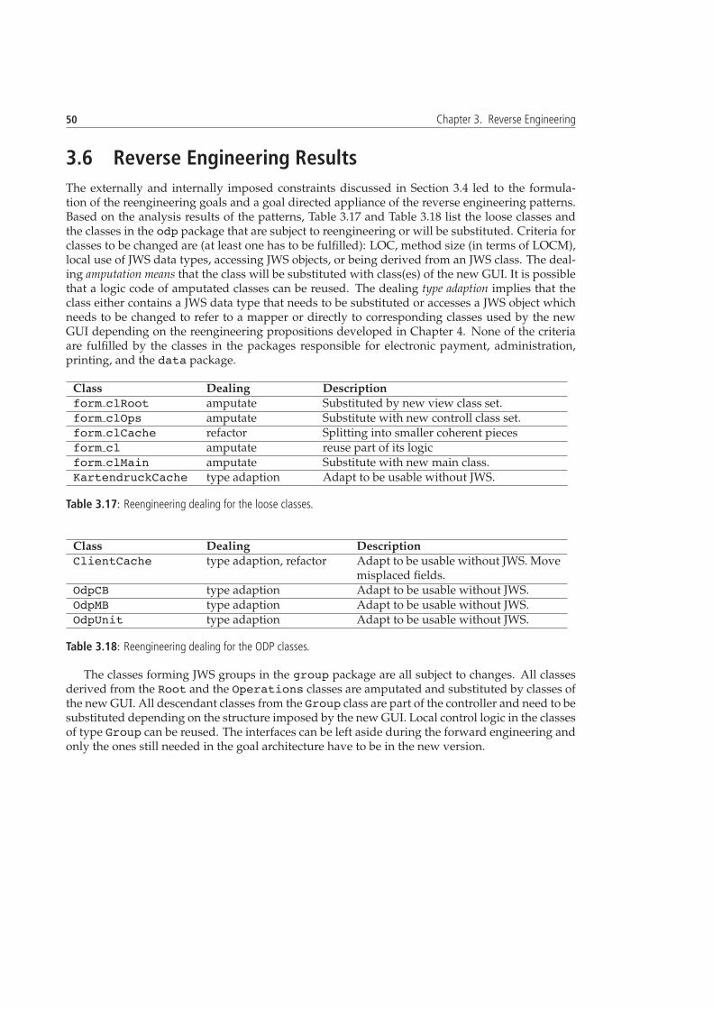
50 Chapter 3. Reverse Engineering
3.6 Reverse Engineering Results
The externally and internally imposed constraints discussed in Section 3.4 led to the formula-tion of the reengineering goals and a goal directed appliance of the reverse engineering patterns.Based on the analysis results of the patterns, Table 3.17 and Table 3.18 list the loose classes andthe classes in the odp package that are subject to reengineering or will be substituted. Criteria forclasses to be changed are (at least one has to be fulfilled): LOC, method size (in terms of LOCM),local use of JWS data types, accessing JWS objects, or being derived from an JWS class. The deal-ing amputation means that the class will be substituted with class(es) of the new GUI. It is possiblethat a logic code of amputated classes can be reused. The dealing type adaption implies that theclass either contains a JWS data type that needs to be substituted or accesses a JWS object whichneeds to be changed to refer to a mapper or directly to corresponding classes used by the newGUI depending on the reengineering propositions developed in Chapter 4. None of the criteriaare fulfilled by the classes in the packages responsible for electronic payment, administration,printing, and the data package.
Class Dealing Descriptionform clRoot amputate Substituted by new view class set.form clOps amputate Substitute with new controll class set.form clCache refactor Splitting into smaller coherent piecesform cl amputate reuse part of its logicform clMain amputate Substitute with new main class.KartendruckCache type adaption Adapt to be usable without JWS.
Table 3.17: Reengineering dealing for the loose classes.
Class Dealing DescriptionClientCache type adaption, refactor Adapt to be usable without JWS. Move
misplaced fields.OdpCB type adaption Adapt to be usable without JWS.OdpMB type adaption Adapt to be usable without JWS.OdpUnit type adaption Adapt to be usable without JWS.
Table 3.18: Reengineering dealing for the ODP classes.
The classes forming JWS groups in the group package are all subject to changes. All classesderived from the Root and the Operations classes are amputated and substituted by classes ofthe new GUI. All descendant classes from the Group class are part of the controller and need to besubstituted depending on the structure imposed by the new GUI. Local control logic in the classesof type Group can be reused. The interfaces can be left aside during the forward engineering andonly the ones still needed in the goal architecture have to be in the new version.

Chapter 4
Reengineering Options
The understanding we have gained of the ticket sales component enables develop a plan for thereengineering under the given constraints (Section 3.4). This chapter discusses the options onhow to proceed and evaluates alternatives of technologies to use. Prototype examples are createdto verify the feasibility of the chosen reengineering path.
4.1 Rebuild from Scratch?
Approximately 40 percent of the code will replaced at the end of the this reengineering project.The question arises: Why not build the whole system from scratch with a new communicationprotocol? The reasons against this option are:
• The controller logic is complex, valuable, and tightly coupled with the communication pro-tocol. A new implementation of the business logic is a risk of failure.
• The human resources for a complete rebuild of the component and the server are not avail-able.
• It is undetermined how the customers of the company would react: How will the acceptanceof completely new solution be? Since the company works closely with its customers, the riskof a flood of incompatible requirements emerges.
• The risk of failure when migrating a system incrementally is smaller than it is when settingup new project.
• A stepwise reengineering deepens the understanding of the controller logic for the docu-mentation and further optimizations.
• The communication protocol is stable and performs sufficiently, there is no urgent need tochange it.
4.2 Alternatives to Java
The next big step in the evolution of the ticket sales component will be the substitution of theimplemented ODP communication protocol. After this step, only the business logic of the con-troller will remain from the current code, the GUI controll logic and communication code will be

52 Chapter 4. Reengineering Options
substituted. This change intent is an opportunity to question the implementation language of thecomponent. Why stay with Java? The alternative to Java is the .Net framework from Microsoft.The reasons to stay with Java technologies—even though they do not have a good client-sidereputation—are:
• The companies personal has more experience with Java technologies than with the .NetFramework.
• The .Net framework is windows operating systems centric, the company wants to offer itscustomers the possibility to run the ticket sales component on different platforms.
• There are many Java open source projects that can be of use for the ticket sales component.
4.3 Graphical User Interfaces
The following sections discuss technical and cognitive principles for GUIs and evaluate Java GUIAPI frameworks.
4.3.1 GUI Principles
The GUI is an important component of many software systems. The development of a GUI isa significant undertaking and the GUIs source code often comprises a substantial portion of theoverall source code [HKR03] of the program. Nowadays, the GUI typically represents 60% of theoverall source of a program [Mem02]. It is easy to write a GUI with the today available editors,but they often generate code that is hard to maintain. A GUI has to be user friendly and easy tomaintain. To allow the user to work comfortably and efficient with a GUI the following usabilityaspects have to be considered:1
• Simplicity: Keep the GUI simple and straightforward.
• Support: Offer informative feedback.
• Familiarity: Build on prior knowledge of the user (from the real world, with other applica-tions or operating systems).
• Obviousness: Make objects and their controls visible and intuitive.
• Encouragement: Make actions predictable and reversible.
• Satisfaction: Reflect the results of actions immediately. Any delay intrudes on the tasks ofthe users and erodes confidence in the system.
• Availability: Make all objects available at all times (no cancel in an operation when addi-tional information is needed).
• Safety: Users have to be protected from making errors.
• Versatility: Allow users to choose the method of interaction that is most appropriate to theirsituation.
1http://www-3.ibm.com/ibm/easy/eou ext.nsf/Publish/6 (2.5.2006).
4.3 Graphical User Interfaces 53
A lot of literature discusses the cognitive aspects of GUIs. The general usability principleslisted above are the most important ones for our purposes. The new GUI of the ticket sales com-ponent needs to consider them.
There is less current literature available that discusses the implementation of GUIs: Whileprinciples regarding good GUI design are well-established, principles regarding which program-ming structures to use with them are not [BH04]. Nevertheless, object-oriented GUI design inpractice consists of positioning widgets in a WYSIWG editor that creates the view code automat-ically and implement the handling of its events in the controller. Oftentimes the separation ofconcerns is already proposed by the code the editors create. The strict realization of the MVC pat-tern is crucial for the future maintainability of a GUI. It is important to keep the size of the classesmaintainable in all layers. This means when new features are added to the GUI, the refactoringpotential in the controller has to be assessed since the view often evolves at the expense of thecontroller (which happened in our case). Periodic refactoring of the controller and the view keepsthe code from degenerating.
4.3.2 GUI Creation Frameworks
GUI creation frameworks for enable the rapid construction of complex GUIs. The two most cur-rent Java GUI creation frameworks are Swing and the Standard Widget Toolkit (SWT). We eval-uate them and chose the one fitting better for the new GUI of the ticket sales component. TheAWT (Abstract Window Toolkit) is not considered in this evaluation because it is a simple toolkitwith limited GUI components, layout managers, and events. “This is because Sun Microsystemsdecided to use a lowest common denominator approach for AWT. Only GUI components definedfor all Java host environments are used. As a result, some commonly used components such asprogress bars are not supported.”2 An alternative approach is to describe GUIs in XML docu-ments that are parsed at runtime and rendered into GUI widgets, for example the open sourceproject Thinlet.3 This concept is very promising, but does not seem mature yet for large GUIsbecause of the restricted widget set and lacking documentation.
Swing, SWT, and JFace
Swing is the primary Java GUI library from Sun Microsystems that aims to look and feel the sameon all platforms [CM04]. The Swing library is part of the Java Foundation Classes (JFC). The ar-chitecture of Swing follows the MVC pattern. Swing has a complete set of GUI components. Theydo not rely on the native widgets of the operating system. Swing components are painted usinggraphic primitives such as lines, rectangles, and text4 Swing emulates native components, buttheir behavior is not always the same which confuses users. The emulation of native componentsreduces the performance of Swing GUIs.
SWT is the GUI toolkit developed by IBM for its Eclipse IDE. It is open source and has anabstract API that is platform independent and uses platform dependent implementations to wraparound native components. The SWT API and SWT behavior are consistent on all supportedplatforms. The SWT classes make direct calls to the operating system using JNI. SWT provides arich set of widgets, wrapping native components if they are available. Otherwise, it emulates thecomponents using Java code [CM04].
Each of the two toolkits is complete and powerful enough to build complex GUIs. Swing isgenerally superior to SWT when used without JFace. Swing has the advantage of being builtinto Java technology, is completely portable, and has a better architecture. Swing also has the
2http://www-128.ibm.com/developerworks/opensource/library/os-swingswt/ (3.5.2006).3http://www.thinlet.com4http://www.onjava.com/pub/a/onjava/2004/02/18/desktop.html (3.5.2006.)

54 Chapter 4. Reengineering Options
advantage for advanced graphical applications. SWT has the advantage of being implementedas a native application which increases the performance and native compatibility of SWT basedGUIs.5 Table 4.1 lines up the advantages and disadvantages of SWT and Swing.
SWT SwingAdvantages Use of native components has
brings good performanceUser friendly native look and feel
Uses MVCPlatform independent
Disadvantages Must include SWT dynamic link li-braries (DLL) for the targeted plat-formFewer literature available com-pared to Swing
Performance not as good asequivalent native programBehavior never completely syn-chronized with native platformdue to emulation
Table 4.1: Line up of SWT and Swing properties.
Our biggest fear when using Swing is a poor performance for the ticket sales application. Themain concern with SWT is the lack of MVC support. JFace is a framework on top of SWT thatallows to implement the MVC pattern and offers more sophisticated widgets. JFace is indepen-dent from the window system in both, its API and implementation, and is designed to work withSWT without hiding it.6 We decided to use SWT together with JFace for the implementation ofthe new GUI. There are GUI editors that allow the generation of Swing and SWT/JFace code, forexample WindowBuilder Pro.7 This gives us the option to easier switch to Swing if SWT causesunexpected problems.
4.4 Unit Tests
The ticket sales component classes to be reengineered do not have a systematic and repeatable testset. Before we can start with the refactorings, we need to establish a test framework. On the classlevel, unit tests for testing controller methods will be established before each refactoring. TheJunit8 test framework will be used to test methods of the controller classes. On the componentlevel, GUI tests offered will be implemented to validate the system as a whole. GUI tests take theperspective of the end user and can be seen as a quality test. There are two general styles of GUItest automation tools:9
• Record: The user records a set of actions on the GUI under test, and the tool is able to replaythose actions later. This approach is simplistic, but fragile (i.e., tests break easily if the GUIchanges).
• Programmatic: The user writes code describing the interaction with the GUI under test. Theapproach is more robust and flexible, but time to program the tests has to be investigated.
We will use GUI automation tests of the record style. If the tests prove too fragile, we willchange to the programmatic style. The unit tests together with the functional GUI test set willresult in a regression test suite. It will fulfill the reengineering goal of a test framework.
5http://www-128.ibm.com/developerworks/opensource/library/os-swingswt/ (5.52006).6http://www-128.ibm.com/developerworks/opensource/library/os-ecgui1/ (5.5.2006).7http://www.windowbuilderpro.com8http://junit.sourceforge.net9http://wiki.java.net/bin/view/Javapedia/TestingGUIApplications (30.5.2006).

4.5 Evaluation of the Proceeding 55
4.5 Evaluation of the Proceeding
Migrate Systems Incrementally pattern recommends to deploy new functionality in frequent incre-ments. The Always Have a Running Version pattern suggests to keep the component functionalduring the reengineering as much as possible. The two patterns are most easily respected bykeeping the current JWS GUI and incrementally adding the SWT GUI to the component. A para-meter given at startup decides which GUI is loaded. A mapper between the main controller andthe two views needs to be installed to route and transform the accesses between the views andthe controller.
4.5.1 SWT and JWS together?
The SWT documentation10 does specify which JDK is at least needed to to run the SWT libraries.The SWT newsgroup states that that SWT only requires a JRE starting from 1.1.8.11 We imple-mented a small GUI component with the SWT API classes and added them to the ticket salescomponent to verify the coexistence of the JWS and SWT API class sets under JDK 1.1.8. The win-dow contains frequently used widgets and ran successfully under the JDK 1.4.2. We added theclasses to the ticket sales component, and tried to deploy the code together with the current SWTJAR under JDK 1.1.8. The result was a runtime error because the SWT class files in the swt.jarlibrary have been crated with a more recent version than JDK 1.1.8. We then tried to compilethe SWT source files with the JDK 1.1.8. This was not successful either, because the current SWTsource files use Java methods that have been added to the JDK after 1.1.8. We decided to abort thispath because the next step would have been to compile older SWT source files and hope that theymatch with the JDK 1.1.8. Even if this worked, the problem that current SWT GUI editors createnon JDK 1.1.8 compliant code remains. The option of migrating incrementally while keeping theJWS GUI toward the new SWT GUI under JDK 1.1.8 is abandoned because we run into too com-plicated compatibility problems. The validation showed the weakness of open source software:The documentation is often not sufficient and the feasibility therefore has to be verified with witha small implementation example.
4.5.2 View or Controller first?
The crucial reengineering steps are the implementation of the SWT GUI and the restructuring ofthe controller. The impossibility of the parallel existence of JWS and SWT libraries restrains thereengineering proceedings. We are left with the choices of either first restructure the controllerunder JDK 1.1.8 or first implement the SWT GUI and then connect it with the controller. Thelogic in the controller works sufficiently reliable, its main problem is the maintenance due to itssize and complexity. The GUI loads slowly and does not correspond with todays expectations ofGUIs. A new GUI is more valuable to the customer than the refactored controller. We thereforeimplement the new GUI before we refactor the control logic. The missing graphical debug supportand unit tests also discourages to first refactor the model. A lot of methods that are candidatesfor refactorings are of return type void and setting up unit tests for them is inefficient becausethey can only be tested whether they trow exceptions. The implementation of the new GUI hasto be stepwise, that is subcomponents of the new GUI have to be built and wired to the controllerto verify their functioning to avoid the risk of failure that comes with a “big bang” migration.Existing GUI components (e.g., the pop-up window to choose an event) can be taken as entitiesto reengineer. On the code level, those entities correspond to a set that consists of a Root, Group,
10http://www.eclipse.org/swt/docs.php (30.4.2006).11eclipse.platform.swt newsgroup, thread: Java and SWT libs compatibility (30.4.2006)

56 Chapter 4. Reengineering Options
and Operations class. This approach also gives us the opportunity to better understand thecontroller logic by looking at the parts used by an entity that is reimplemented. First creating theview is also the fastest way to a higher JDK with debug support.
4.5.3 Mapper or Direct Access to the View?
The non amputated controller logic in form clCache cannot use JWS types to store data to beable to run with the SWT GUI. This leaves us with two possibilities to set up the communicationbetween the controller and the new SWT view:
• Wire the SWT GUI directly with the controller. All view accesses in the controller needto be substituted with the corresponding accesses to SWT GUI elements and the used JWStypes need to substituted in the controller.
• Communicate via a mapper. Substitute the used JWS data types in the model and makemapper classes for the JWS classes accessed in the model. The mapper classes delegate themodel accesses to the right SWT element in the view.
Wire the SWT GUI directly to the controller increases the risk of failure because two large stepsare made (i.e., creating the whole SWT GUI, and wiring it with the controller) before the compo-nent is able to run again. The controller is out of order for the time the new GUI is wired. Wetherefore chose to create a mapper. This means more work, but allows to verify that the controllercan run without the JWS classes. In a first step, we substitute the JWS data types used in thecontroller with standard JDK data types. We then create a mapper that will consist of the set ofJWS classes that are accessed by the controller. The mapper will delegate the accesses from thecontroller to the view (the mapper therefore knows JWS classes). The result is a JWS-free con-troller that can via the mapper access the JWS GUI. We are then ready to gradually implementand test the new SWT GUI, duplicate the JWS mapper and adapt it for the SWT GUI. Mappingsto the not yet implemented SWT GUI parts are substituted with dummy accesses. The accessesfrom the controller to the view remain the same, but the transformation of data and the routingto the view are adapted to the SWT GUI structure. The mapper solution allows to have a runningversion during the construction of the SWT GUI and incrementally migrates to the target com-ponent. The events passed to form clCache from the view do not have to mapped because theold AWT Event class is still available in JDK 1.5 for backwards compatibility. The considerationsmade in these sections lead to the beneath listed proceeding for the core reengineering work:
• Substitute the JWS data types in the controller with standard JDK data types and constructsthereof
• Create mapper classes for the used JWS classes in the controller classes
• Fill the mapper classes with view methods accessed by the controller
• Fill the methods in the mapper with data transformations where necessary and link them tothe corresponding method in the JWS GUI.
• Test the component with newly added mapper
• Incrementally create the SWT GUI.
• Incrementally adapt the mapper for the SWT GUI. Yet unused mapper methods either re-turn dummy values or are empty in the case of a setter mapping.
• Deploy the SWT ticket sales component

4.6 Prototype the Target Solution 57
• Refactor the controller
• Remove the SWT mapper
• Deploy the refactored SWT ticket sales component
4.6 Prototype the Target Solution
We have to verify the feasibility of the critical steps, that is the substitution of JWS data types inthe controller, the implementation of the mapper, and the controller refactorings. A prototypeexamples of the solution have to be implemented. This also allows to asses the amount of workneeded and its complexity.
4.6.1 Feasibility of JWS Type Substitutions
JWS data types locally used in controller classes that are not amputated have to be substitutedwith a JWS free alternative. We selected the JWS type AttributeList used in the OdpUnitclass which stores a list of another JWS type, Attributes. The sparse JWS documentation ofthe two types has been studied to understand their purpose. We then searched all of its usedmethods in the component. We created the two types and added them to the component. Totest their correctness, we ran the JWS and the substitute types in parallel, that is whenever aninstance of the original type is created or accessed, we performed the same operations with thesubstitute types. Print statements have been added to the code after operations on the JWS andthe substitute types are performed to verify the correctness. The implementations of the substitutetypes is feasible. The code listed in Section A.1.
4.6.2 Feasibility of the Mapper
The accesses to JWS view objects in the controller classes that are refactored need to be foundand mapped. The JWS GUI view and the new SWT view code need to be able to function withthe same controller classes that are refactored. The mapper classes need to have the same classhierarchy relations as the accessed JWS classes to conform to polymorphism (specialized objectscan be held by more general object types).
We created at prototype mapper for the accessed JWS types and instances used in the odppackage. The ODP classes that contain or access JWS objects are listed in Table 3.18 in Section 3.6.For each ODP class that accesses objects of a JWS type, we created a mapper class when a JWSobject in the view was accessed or used for comparison (i.e., instanceof). We had to respect theJWS class hierarchy for the mapper classes. We filled up the mapper classes with the signaturesof JWS methods used by the ODP classes. The methods contain the original JWS method thataccesses the view and type transformations for the cases where a JWS type is returned to the ODPclasses from the view or sent by the ODP classes to the view. The methods are poorly describedin the JWS API documentation, it is not always clear how the JWS types store data, and how thedifferent JWS classes that form a group interact with each other. We added comments to methodsthat where not perfectly understood for the case of buggy behavior. The mapper classes referencethe JWS view objects. A main mapper class has been created to hold the used mapper classes.The main mapper class is instantiated right after the form clRoot class to enable the referencesto it. Section A.2 lists an example of a mapper class.
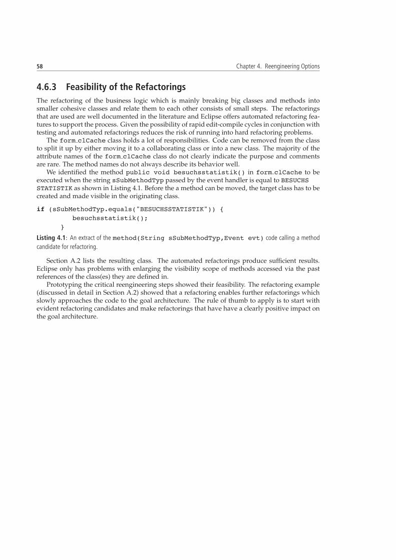
58 Chapter 4. Reengineering Options
4.6.3 Feasibility of the Refactorings
The refactoring of the business logic which is mainly breaking big classes and methods intosmaller cohesive classes and relate them to each other consists of small steps. The refactoringsthat are used are well documented in the literature and Eclipse offers automated refactoring fea-tures to support the process. Given the possibility of rapid edit-compile cycles in conjunction withtesting and automated refactorings reduces the risk of running into hard refactoring problems.
The form clCache class holds a lot of responsibilities. Code can be removed from the classto split it up by either moving it to a collaborating class or into a new class. The majority of theattribute names of the form clCache class do not clearly indicate the purpose and commentsare rare. The method names do not always describe its behavior well.
We identified the method public void besuchsstatistik() in form clCache to beexecuted when the string sSubMethodTyp passed by the event handler is equal to BESUCHSSTATISTIK as shown in Listing 4.1. Before the a method can be moved, the target class has to becreated and made visible in the originating class.
if (sSubMethodTyp.equals("BESUCHSSTATISTIK")) {besuchsstatistik();
}
Listing 4.1: An extract of the method(String sSubMethodTyp,Event evt) code calling a method
candidate for refactoring.
Section A.2 lists the resulting class. The automated refactorings produce sufficient results.Eclipse only has problems with enlarging the visibility scope of methods accessed via the pastreferences of the class(es) they are defined in.
Prototyping the critical reengineering steps showed their feasibility. The refactoring example(discussed in detail in Section A.2) showed that a refactoring enables further refactorings whichslowly approaches the code to the goal architecture. The rule of thumb to apply is to start withevident refactoring candidates and make refactorings that have have a clearly positive impact onthe goal architecture.
Chapter 5
Reengineering Plan
A reengineering plan has to be developed based on the goals set in Section 3.4, the informa-tion revealed about the ticket sales component during the reverse engineering, and the discussedoptions in Chapter 4. The plan states what needs to be done and gives templates for the imple-mentation.
5.1 Overview
Figure 5.1 shows the goal architecture for the ticket sales component. The GUI constitutes of ahierarchy of SWT composites. A composite is the SWT pendant to a JWS group. Each compositehas its own event handler which calls the desired methods in the set of operation classes thatcontroll view, application model and communication. Communication logic and the applicationmodel are separate components to foster software reuse. The overview to the reengineering planincluding milestones is given in Table 5.1. During the controller refactoring, JUnit tests haveto be introduced whenever code is regrouped, changed or added. This allows to grow a testbase incrementally and rapid edit-compile-test cycles. Insufficiently commented code during theforward engineering has to be commented to be used by JavaDoc. During the reengineering,the extension of the component will be suspended and maintenance of the business logic will bereduced to a minimum.
5.2 Substitute Local JWS Elements in Controller
Table 5.2 shows all non amputated controller classes that contain locally used JWS data types. TheJWS types to be substituted are listed together with their substitutes. The data types that are sentto the view are transformed back into JWS types in a temporary mapper class. An implementationexample of a custom types is given in Section A.1.
5.3 Create JWS Mapper
Figure 5.2 shows the mapper hierarchy that has to be created for the JWS types. The hierarchy forthe custom-made classes derived from the JWS Group class in the group package also need tobe constructed (a part of them is shown in Figure 3.7 in Section 3.3.1) and added to the hierarchy.The “M” at the end of each class name indicates “mapper class” to avoid mistakes. Only the view

60 Chapter 5. Reengineering Plan
Figure 5.1: The architecture of the reengineered ticket sales component.
classes accessed in the non amputated controller classes need to be created, but the ordering of theoriginal JWS hierarchy has to be respected for polymorph functions in the controller. The classesonly need to contain the methods used in the controller, mostly setters and getters. If JWS typeshave to be returned or obtained, the mapper also needs to make the type conversion. A part ofthe JWS classes in the controller are only used in conditional statements to find out of what typea received object is. Section A.2 gives an example of an implemented mapper class.
The mapper classes are declared in a main mapper class which also sets references to the corre-sponding elements in the form clRoot class. Its instantiation follows right after the form clRootclass has been created in the form cl class.
5.4 Build SWT GUI
We create the new GUI from top to bottom, that is we start with substituting the JWS main panel,proceed with the definition of its sub-panels, until we are down to the basic widgets a panel holds.form clRoot contains all elements the GUI consists of. The class holds the information aboutthe relations between the panels. It is not recognizable from the names of the widgets to what partof the GUI they belong (widgets containing text visible to users receive the text from the databaseto enable the support several GUI languages). We use the Java Workshop editor to visualize theformcl Root class. This allows us to associate the names of GUI elements with their look. Theiterative procedure to reimplement the GUI is as follows:
• In the Java Workshop editor, chose the panel that is closest to the root panel of the JWS panelhierarchy.
• Look up the name of the panel and which widgets are added to it in the form clRoot class.
• Implement the corresponding SWT widgets in a SWT composite
• Find the events in the form clOps class that are handled by the substituted panel
• Reimplement the corresponding event handlers in a separate class (Listener interfaces)

5.4 Build SWT GUI 61
Step Description MilestoneSubstitute JWS ele-ments in controller
The controller classes need to be freedfrom locally used JWS data types. Sub-stitutes for JWS elements can be fittingJava types, or custom JDK type basedconstructs.
M1: The controller is freeof locally used JWS types.The component can stillbe run under JWS.
Create mapper A class hierarchy analog the JWSclasses in the controller that access theview has to be created. The mapperclasses have to be filled up with all ac-cessed view methods in the controller.Fill the methods in the mapper withdata transformations where necessaryand link them to the correspondingmethod in the JWS GUI.
M2: The component runsproperly under JWS withthe mapper.
Build SWT GUI Incrementally create SWT GUI. TheGUI elements are connected withthe mapper for JWS. The mapper isadapted in a way that the controllerand the already implemented viewparts can run together. Automatedtests of style record have to be created.
M3: The ticket sales com-ponent has a new SWTGUI, follows the MVCpattern and can be rununder JDK 1.5. A newversion of the componentcan be deployed.
Refactoring of thecontroller
The form clCache controller class issplit up. New classes containing dataand their handling methods are cre-ated. Misplaced methods are movedto classes containing features that usethem most. Large methods are split up.
M4: The god class issplit up into manageablepieces. The code ofthe component is reengi-neered.
Create technical doc-umentation
The architecture of the component isdescribed, UML diagrams are given,and the use cases are related to thecode.
M5: A documentation ofthe component is estab-lished on the Wiki systemof the company.
Update user docu-mentation
The outdated use cases are updated M6: The user manual issynchronized to the cur-rent state of the ticketsales component.
Table 5.1: Overview of the reengineering plan including milestones.
Class JWS Type Substitute TypeOdpUnit AttributeList see Section A.1ClientCache AttributeManager Custom typeform clCache ColumnList Object[]
Table 5.2: List of JWS types in the controller that need to be substituted.
• Connect the composite to the mapper
The result after each iteration is a SWT composite class that connected to the mapper and anevent handler class directly accessing the form clCache class. Code from custom JWS groups

62 Chapter 5. Reengineering Plan
Figure 5.2: The class hierarchy of the JWS mapper classes.
can be reused.The resulting GUI will look similar to the existing one. The main difference is that events are
now handled in the controllers of the composites and are not delegated up the GUI hierarchyanymore to a main event handler.
5.5 Controller Refactoring
A mixture of static and dynamic observations has to be made to be able to find couplings ofmethods and attributes that can be moved into other classes. The size of the class and the limitedability to follow the execution path make it hard to give a perfect plan of how to split up theclass. The refactoring reality is to start out with moving out clearly coupled refactorings and thenidentify more cohesive methods and attributes as the understanding of the code improves due tothe newly added GUI and the already made refactorings.
The goal is to split up the form clCache class into smaller classes that are responsible foreither communication with the server, holding the state attributes1 of the application model, orexecuting methods called by the event handler. The first step is to split up the operations ofform clCache into classes responsible for a subject, for example managing client data. We usedthe criteria listed beneath to find methods that work on the same subject.
• Method names
• The method( String sSubMethodTyp, Event evt) conditional method inform clCache which selects the methods to be executed upon the arrival of an event fromthe view.
1Data Containers a bad smell, but we prefer to have the application model separated from other controller components.

5.5 Controller Refactoring 63
Considering the events is helpful to see to which GUI feature the code is coupled if the namesof the methods do not allow deduce their purpose. Table 5.3 summarizes the identified subjectsrelated methods resulting from the dynamic and static observation of the form clCache class.If a method has several signatures, all methods with the same name belong to the same subject.
Subject Method(s)Subject Method(s)Application startup checkClientVersion, initApplication, loginPayment getBKZahlung, receiveCardData, bkMessage,
getSqlString, getTerminalNummer,getThisPaymentConnection, handleZahlungglobal bkZahlung, mkl aktiv,receiveCardData, retourPreis,retourPreisMain
VerkaufController init verkauf dlgTicket barcodes processBarCode, receiveBarCodeCustomer management check email, check string,
delete kunderelation, delete werbemittel,getMediumRessortVector,insert kunderelation, iud kunde,iud kunderelation, iud kunde,iud werbemittel, reset kunde, select kunde,select kunderelation, select werbemittel
List management ok List, remove ShuffleList, select ListTicket logic check kombiticketPreisGruppe,
click kombiticketTicket sales checkZahlart, click alleskombiticket,
getSonderkonditionVector,getSortedEnumeration, getSortedVector,gutschein, init verkauf dlg,readVerkaufListeDialog, select kombiticket,select kombiticketvorstellung,setVerkaufListeDialog, verkauf,verkaufcancel, verkaufja, verkaufnein,verkaufsliste
Hall map controll click, clickProductPlaces, fillLeft,getAndclickNextFreePlaces,getNextFreePlaces, select canvas,setze status
Merchandise clickArtikel, select ArtikelPreisVector sorting compareStatusELSType converters convert, StringtoOdpVectorDatabase operations do commit, do rollbackGuided tour fillLeft, fuehrungsKalenderWindow control getDialogOpen, methodGUI, resetInfoText,
switch kundenmaskecontinued on next page
64 Chapter 5. Reengineering Plan
continued from previous page
Subject Method(s)Application model getPGColorTicket printing kartendruck, loadProgress, printException,
printKarteOrders select bestellung, select bestellung detail,
select bestellungs liste,storno bestellung, wandle bestellung
Subsripttions vorst abo storno, vorst abo zuo,wahlabobuchen
Table 5.3: Subjects representing new classes to split up the form clCache class.
Not all methods are listed in Table 5.3 for the following reasons:
• They can be substituted by SWT widget controll methods
• They represent dead code
• The information they retrieve from the JWS groups can be obtained by SWT typed events.
• Their purpose is unclear or they cannot clearly be associated with a subject
The methods in Table 5.3 have to be moved first before deciding what to do with the nonassociated methods. The classes they are moved to have to be derived from ClientCache to en-sure the functionality of methods that communicate with the server. The proposed move methodrefactorings will make further refactorings visible and clarify the unassociated methods of theform clCache class. The methods have to be moved without consideration of their interfaces.The interfaces can be split up or are not needed anymore because the functionality they accesshas moved to an architecturally more purposeful place. Attributes that are only coupled to onesubject have to be moved into the newly created subject classes. Attributes used by many meth-ods have to be moved to the application model. After the methods in Table 5.3 have been movedinto new classes, the communication logic have to be separated from the operation methods. Thisis done by extracting the communication code into classes. The operation methods that need toaccess the server will call communication methods and passing the parameters used for the com-munication protocol. Listing 5.1 shows the communication with the server. A vector to hold datato be transferred to the server via socket communication is first cleared. The parameters for thedatabase query are added to the vector and the communication is started. Each extracted com-munication class will hold the same communication code structure as shown in Listing 5.1. Thecommunication classes can be merged together to and a case statement is used to set the hardcoded string as the first element of the vector. A for statement is used to load the vector with thepassed values from the method call of the operations component.
clearParameter();add(new OdpString("WANDLE_BESTELLUNG"));add(new OdpInt(iLangCode));add(new OdpString((String)fGUI.BestellnummerTextField.get("text")+":"+verkauftyp));
start(ObjectOdp.TRANSFER_SYNCHRON);setCursor(Frame.DEFAULT_CURSOR);

5.5 Controller Refactoring 65
recvErrorList();
Listing 5.1: Use case of the ODP communication protocol.
Table 5.4 shows methods that are misplaced, they access data in an other class and can bemoved the accessed class. Only methods that are not moved to amputated classes are listed. Themethods accessing amputated classes need to be moved and adapted to the substituting SWTcomposite.
Method Target classgetCmdLineArgs, getFontButtonSize,getFontSeatSize, getRefreshTime
ParamTable
getColorScheme OdpColor
Table 5.4: Methods that need to moved to an existing class or a substitute thereof.
The method(String sSubMethodTyp,Event evt)method in form clCachewhich un-der JWS handles all events of non custom GUI widgets is substituted with a set of SWT event han-dling classes that handle events issued by the composite classes when the new GUI is connectedto the operations component.
The move method refactorings can be done with the Eclipse move refactoring feature. Typically,not all referred variables are visible in the target class. They have to be adapted manually, eitherby making them public or by the creation of getter and setter methods for them. A unit test forthe method that is moved has to be created before each refactoring and the test set has to be runafter each change. Additionally, it is advisable to run the whole ticket sales component after eachrefactoring and verify at runtime that the moved functionality has not been broken. Figure 5.3shows the UML class diagram of a part of the classes incorporating the subjects proposed inTable 5.3. Only moved methods are shown, not inherited methods to implement from the abstractsuperclass ClientCache. They have been moved successfully for prototype purposes and tocollect experience with the Eclipse refactoring functionality.
Figure 5.3: UML class diagram of classes that contain methods moved from the form clCache class.
The coarse refactoring is done after the form clCache has been split into communication,application model and operation classes. The new structure of the ticket sales component willimply further refactorings to optimize it. A part of the moved methods are too big in terms ofLOC, refactorings to split them are necessary. Large methods typically access the view to getinput data from a form or to display results obtained from the database. Such code sequences

66 Chapter 5. Reengineering Plan
are candidates to be extracted into a method. The refactoring has to be stopped when the targetcontroller architecture shown in Figure 5.1 has been achieved and the classes constituting it arehave become more comfortable to maintain, that is if they contain a reasonable amount of LOCand are well structured.
ClientCache contains variables to set the authorization of features to a user at programstartup. They have to be moved to a class in the application model.
The controller refactoring described mainly consists of move method, extract method, and movefield refactoring steps. Eclipse masters all of them sufficiently, but there still remains handwork todo. The procedure to move a method is:
• Move attributes(s) hat are used by the method in a new class
• Change the initialization methods of the originating class to refer to instances of the newclass
• Move the method(s) in the new class
• Update the method accesses to the new class
5.6 Documentation
The last reengineering steps are to establish a technical documentation of the ticket sales compo-nent and to update the user manual. The goal of the technical documentation is to give a quickoverview of the component to developers and maintainers who get in touch with it for the firsttime. The documentation has to contain architectural views and use cases of the component.UML diagrams such as state, sequence, and collaboration have to be used to explain the ticketsales component.

Chapter 6
Conclusions and Outlook
6.1 Contribution
This thesis applied techniques and tools to an object-oriented legacy system to develop a reengi-neering plan for the company. The thesis can be used as practical reference for the organizationalproceeding in client-side software reengineering projects. The work delivers detailed exampleson how to execute the steps of the reengineering process.
6.2 Experiences Made
Reengineering should be done on a regular basis, and not when it becomes unavoidable. Legacysystem reengineering is labor intensive and complex due to the various aspects that have to beconsidered. The reengineering work done with tools proved that they are of use for the reengi-neering process, but they are not crucial for success. The key factors are the organization ofthe project, reengineering experience, and technical knowledge. The most difficult parts wereselectively acquire a sufficient understanding the system and make the right reengineering deci-sions that shape the future of the system. The applied pattern-oriented reengineering frameworkproved to be effective to coordinate the activities involved in reengineering. The today availablefeatures of commercial, academic, and open source reengineering tools have a lot of potentialto be improved. As software systems tend to grow bigger and more complex, the need of toolassistance needs to rise to successfully reengineer them.
6.3 Outlook
The company will implement the proposed changes of the ticket sales component. Fine-grainedreengineering steps that make the component more maintainable will be undertaken, such as de-tection of duplicated code and transformation of long conditional statements to polymorphismsto use the strength of object-oriented programming.

Appendix A
Source Code Listings
A.1 JWS Substitute Data Types
Listing A.1 shows the substitute type for the JWS data type Attribute which is needed for thesubstitute type AttributeList implemented in Listing A.2.
A.2 Mapper Class
Listing A.3 shows a mapper class for the JWS type Group.
A.3 Move Method Refactoring Example
The StatistikController class listed in Listing A.4 to hold the moved method besuchs-statistik is derived from the ClientCache communication class. In a further refactoringstep, the communication has to be separated from the view access. The besuchs statistikmethod can be changed to obtain a parameter which pases the data needed from the view. Thebesuchsstatistik method can be changed to return OdpVector that holds the results fromthe data base which enables to move the showTextDialog out of the communication method.The form clCache reference given to besuchsstatistik is then needed anymore, since therecvErrorList(), add(Odp odp), and get(int i) methods are inherited from ClientCache.
Note: The example contains the JWS AttributeMmanager class because it has not been sub-stituted in the form clCache class in the mapper prototype.

70 Chapter A. Source Code Listings
package jwsSubstitutes;
/** Substitute Type for JWS Atrribute
* Needs to store: ( "java.lang.String", odpsTitle.value, 6)
*/public class Attribute {
public String attString = null;public Object attrOjbect = null;public int attrInt = 0;
Attribute(String attStringValue, Object attrOjbectValue,int attrIntValue){attString = attStringValue;attrOjbect = attrOjbectValue;attrInt = attrIntValue;}// Sets the value of the attribute.public void setValue(Object value){
attrOjbect = value;}
public Object getValue(){return this.attrOjbect;
}}
Listing A.1: Substitute type for the JWS type Attribute.

A.3 Move Method Refactoring Example 71
import java.util.Hashtable;
/** Substitute Type for JWS AtrributeList
*/
public class AttributeList {
private Hashtable attributetable = new Hashtable() ;
public Attribute get(String name){return ((Attribute)attributetable.get(name));
}
public String resolveAlias(String name){if (attributetable.containsKey(name))
return name;else return null;
}
public void add(String name, String type, Object defaultValue,int flag){
Attribute m = new Attribute(type, defaultValue, flag);attributetable.put(name, m );
}
public void add(String name, String type, Object defaultValue){add(name, type, defaultValue, 0);
}}
Listing A.2: Substitute type for the JWS type AttributeList.
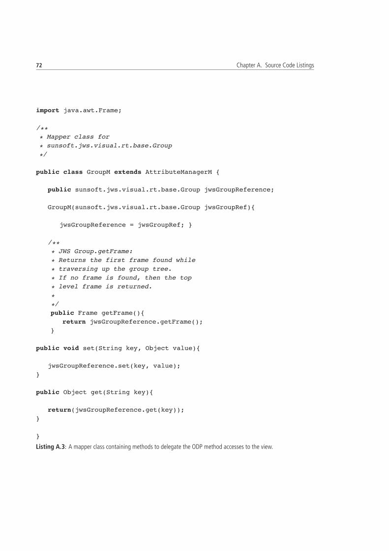
72 Chapter A. Source Code Listings
import java.awt.Frame;
/*** Mapper class for
* sunsoft.jws.visual.rt.base.Group
*/
public class GroupM extends AttributeManagerM {
public sunsoft.jws.visual.rt.base.Group jwsGroupReference;
GroupM(sunsoft.jws.visual.rt.base.Group jwsGroupRef){
jwsGroupReference = jwsGroupRef; }
/*** JWS Group.getFrame:
* Returns the first frame found while
* traversing up the group tree.
* If no frame is found, then the top
* level frame is returned.
**/public Frame getFrame(){
return jwsGroupReference.getFrame();}
public void set(String key, Object value){
jwsGroupReference.set(key, value);}
public Object get(String key){
return(jwsGroupReference.get(key));}
}
Listing A.3: A mapper class containing methods to delegate the ODP method accesses to the view.
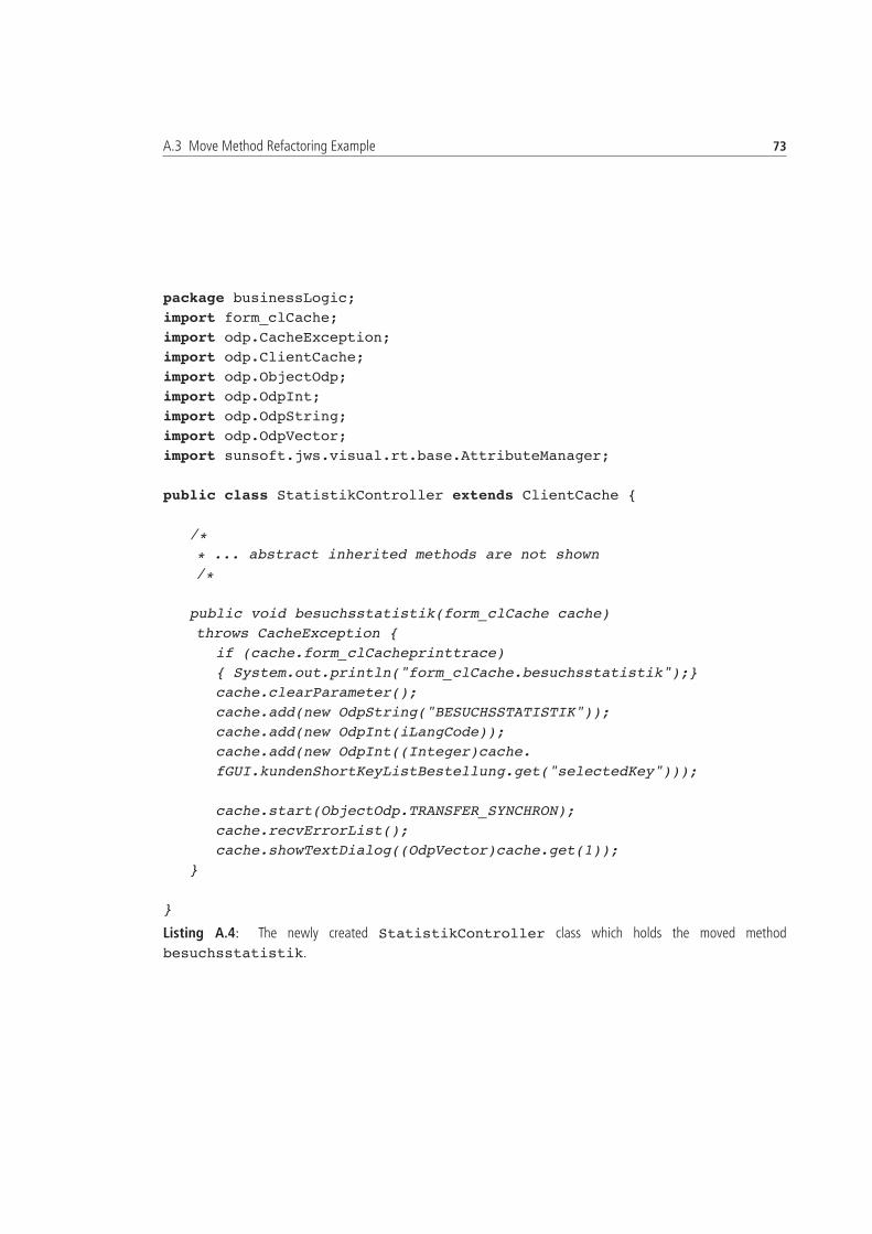
A.3 Move Method Refactoring Example 73
package businessLogic;import form_clCache;import odp.CacheException;import odp.ClientCache;import odp.ObjectOdp;import odp.OdpInt;import odp.OdpString;import odp.OdpVector;import sunsoft.jws.visual.rt.base.AttributeManager;
public class StatistikController extends ClientCache {
/** ... abstract inherited methods are not shown/*
public void besuchsstatistik(form_clCache cache)throws CacheException {
if (cache.form_clCacheprinttrace){ System.out.println("form_clCache.besuchsstatistik");}cache.clearParameter();cache.add(new OdpString("BESUCHSSTATISTIK"));cache.add(new OdpInt(iLangCode));cache.add(new OdpInt((Integer)cache.fGUI.kundenShortKeyListBestellung.get("selectedKey")));
cache.start(ObjectOdp.TRANSFER_SYNCHRON);cache.recvErrorList();cache.showTextDialog((OdpVector)cache.get(1));
}
}
Listing A.4: The newly created StatistikController class which holds the moved method
besuchsstatistik.


Appendix B
List of Used Software Tools
• Eclipse http://www.eclipse.org
• Creole: http://www.thechiselgroup.org/
• CodeCrawler http://www.iam.unibe.ch/!scg/Research/CodeCrawler/
• jFamix http://jfamix.sourceforge.net/eclipse/index.html
• Omondo UML http://www.omondo.com/
• Java Metrics http://sourceforge.net/projects/metrics

76 Chapter B. List of Used Software Tools

References
[Arn94] Robert S. Arnold. Software Reengineering: A Quick History. volume 37(5), pages 13–14. Communications of the ACM, 1994.
[BH04] Judith Bishop and Nigel Horspool. Developing principles of GUI programming us-ing views. In Proceedings of the 35th technical symposium on Computer science education(SIGCSE-04), volume 36, 1 of SIGCSE Bulletin, pages 373–377, New York, 2004. ACMPress.
[CC90] Elliot J. Chikofsky and James H. Cross. Reverse Engineering and Design Recovery: ATaxonomy. In IEEE Software, pages 23–32, Amsterdam, The Netherlands, September1990. IEEE Computer Society.
[CM04] N. Chen and K. K. Ma. Java’s future: Challenge and opportunity. IT Professional,6(4):19–27, 2004.
[DDN03] Serge Demeyer, Stephane Ducasse, and Oscar Nierstrasz. Object-Oriented ReengineeringPatterns. Morgan Kaufmann, 340 Pine Street, Sixth Floor, San Francisco, CA 94104,USA, 2003.
[FBB+99] Martin Fowler, Kent Beck, John Brant, William Opdyke, and Don Roberts. Refactoring– Improving the Design of Existing Code. Addison-Wesley, Massachusetts, 1999.
[FPG03a] Michael Fischer, Martin Pinzger, and Harald Gall. Analyzing and Relating Bug ReportData for Feature Tracking. In Proceedings of the 10th Working Conference on Reverse En-gineering, pages 90–99, Victoria, B.C., Canada, November 2003. IEEE Computer SocietyPress.
[FPG03b] Michael Fischer, Martin Pinzger, and Harald Gall. Populating a Release History Data-base from Version Control and Bug Tracking Systems. In Proceedings of the 19th Inter-national Conference on Software Maintenance (ICSM), pages 23–32, Amsterdam, Nether-lands, September 2003. IEEE Computer Society Press.
[HKR03] Christopher J. Howell, Gregory M. Kapfhammer, and Robert S. Roos. An examinationof the run-time performance of gui creation frameworks. In PPPJ ’03: Proceedings ofthe 2nd international conference on Principles and practice of programming in Java, pages171–176, New York, NY, USA, 2003. Computer Science Press, Inc.
[Lan03] Michele Lanza. CodeCrawler – A Lightweight Software Visualization Tool. In Proceed-ings of VisSoft 2003 (2nd International Workshop on Visualizing Software for Understandingand Analysis), pages 51–52. IEEE Comptuer Society Press, 2003.

78 REFERENCES
[Lan04] Michele Lanza. CodeCrawler — Polymetric Views in Action. In Proceedings of ASE2004 (19th IEEE International Conference on Automated Software Engineering), pages 394–395, 2004.
[Mem02] Atif M. Memon. Gui testing: Pitfalls and process. IEEE Computer, 35(8):87–88, 2002.
[NDG05] Oscar Nierstrasz, Stephane Ducasse, and Tudor Gırba. The Story of Moose: an AgileReengineering Environment. In Proceedings of the European Software Engineering Confer-ence (ESEC/FSE 2005), pages 1–10, New York NY, 2005. ACM Press.
[otICS98] Software Engineering Standards Committee of the IEEE Computer Society. IEEE Std.1219-1998: IEEE Standard for Software Maintenance. New York, USA, 1998. IEEE.
[PGFL05] Martin Pinzger, Harald Gall, Michael Fischer, and Michele Lanza. Visualizing MultipleEvolution Metrics. In Proceedings of the ACM Symposium on Software Visualization, pages67–75, St. Louis, Missouri, 2005. ACM Press.
[RR02] Claudio Riva and Jordi Vidal Rodriguez. Combining Static and Dynamic Views forArchitecture Reconstruction. In Proceedings of the Sixth European Conference on SoftwareMaintenance and Reengineering (CSMR). IEEE Computer Society, 2002.
[Szy98] Clemens A. Szyperski. Component Software. Addison Wesley, 1998.