Embed Size (px)
Citation preview
Diode Laser Modules and Pattern Generators
2011 Catalog
Superior Reliability & Performance

All Coherent product names are trademarks of Coherent, Inc.*All products indicated by an asterisk are registered trademarks of their respective companies.
How to Contact UsContact Us by Phone
Coherent, Inc.(800) 527-3786 or (408) 764-4983
Benelux: +31 (30) 280 6060
China: +86 (10) 6280 0209
France: +33 (0)1 6985 5145
Germany: +49 (6071) 968333
Italy: +39 (02) 34 530 214
Japan: +81 (3) 5635 8700
Korea: +82 (2) 460 7900
United Kingdom: +44 (0) 1353 658833
Contact Us by Email
Laser Products: [email protected]
Laser Measurement: [email protected]
Service: [email protected]
• Toll Free: (800) 343-4912 • Tel: (408) 764-4042 • Fax: (503) 454-5727 3
Introduction
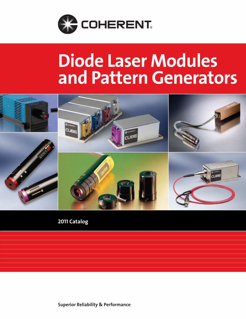
Coherent’s Laser Diode Modules combine the technology of the diode laser with quality optics, sophisticated electronics and rugged modular packaging to provide a reliable laser source suitable to a variety of application needs.
Diode Laser Modules and Systems
Applications:Confocal MicroscopyFlow CytometryMedical Alignment3D Contour MappingGenomicsHigh Speed Industrial InspectionHomeland SecurityEnvironmental MonitoringMachine Vision
CUBE
Radius
Diode Laser Modules
Accessories

Superior Reliability & Performance • www.Coherent.com • [email protected]
IntroductionThe Lasiris Advantage 6
Diode Laser Modules and Systems 7
Diode Laser SystemsCUBE 8-19
CUBE FP 20-27
Radius 28-30
Diode Laser ModulesULN 31- 32
Cross-Hair Line Generators 33
Focusable Line Generator Modules 34-35
Line Generator Diode Laser Modules 36-37
Miniature Diode Laser Modules 38-39
Application Primers 40-43
Lasiris Structured Light LasersLasiris SNF 44-47
Lasiris Mini 48-51
Lasiris DLS and DLSC 52-55
Lasiris GLL 56-59
Lasiris TMFL 60-63
Lasiris ColdRay 64-67
Lasiris PowerLine 68-71
Lasiris Green PowerLine 72-75
Lasiris Magnum II 76-79
Lasiris Flat Top Projector 80-83
Diode Laser Modules and Pattern GeneratorsTable of Contents
Diode Laser Systems
Diode Laser Modules
Lasiris Structured
Light Lasers
Accessories
• Toll Free: (800) 343-4912 • Tel: (408) 764-4042 • Fax: (503) 454-5727 5
AccessoriesInterference Filters 84-85
Diode LabLaser Universal Power Supply 86
Universal Diode Laser Module Power Supply 87
Variable Angle Diode Laser Mounts 88
FieldMaxII-TO 89
LaserCheck 89
High-Sensitivity Thermopile Sensors 90
Diode Laser Modules and Pattern GeneratorsTable of Contents
Diode Laser Systems
Diode Laser Modules
Lasiris Structured
Light Lasers
Accessories

Superior Reliability & Performance • www.Coherent.com • [email protected]
The Coherent Lasiris advantageCoherent’s world-renowned Lasiris™ laser’s transforms the familiar laser dot into a wide range of structured light patterns including single and multiple laser lines with uniformity down to ±15%. Straight laser lines are projected by allowing one dimension of light to fan out while maintaining tight control over the other, result-ing in a uniform sheet-of-light.
What distinguishes the Lasiris family of laser’s from conventional lasers (with cylindrical optics) is the evenness of the illumination pattern. Lasiris lasers incorporate a patented optical laser line generator that eliminates Gaussian distribution of the light, result-ing in the most uniform laser lines on the market. The design provides superior quality light patterns while avoiding the intricacies of installation alignment and detector calibration.
Increase the Performance and Reliability of your Application
Make full use of available powerThe Lasiris non-gaussian line shows a sharp cut-off at the ends, enabling the detector to utilize the full length of the line of light instead of only the center region. All the power of a Lasiris laser is put to use.
The Lasiris AdvantageIntroduction
Simple no-nonsense calibrationDetector calibrations are easier because of the uniform intensity profile along a Lasiris line length.
Industrial-grade protectionIn addition to quality optical components, Lasiris lasers are protected from over-voltage, over-temperature, reverse-polarity, and ESD electrostatic discharge, com-plete with a full 2-year guarantee for selected lasers.
Eliminate Laser Safety Problems
Eye-safe lasersSince there is no hot spot and the laser energy is better spread along a Lasiris laser pattern, the safety rating of the structured light projector can be kept at the class II level for most model where other lasers cannot.
Find the Solution that is Right for You
Over 48,000 off-the-shelf standard solutionsWith so many standard possibilities as well as cus-tom and OEM capabilities, whether you need a larger housing, a specific wavelength, a shorter cable, or a completely new type of laser, do not hesitate to test our skills!
Diode Laser Systems
Diode Laser Modules
Lasiris Structured
Light Lasers
Accessories

• Toll Free: (800) 343-4912 • Tel: (408) 764-4042 • Fax: (503) 454-5727 7
Diode Laser Systems
Diode Laser Modules
Lasiris Structured
Light Lasers
Accessories
Quality solutionsBased on size, reliability and cost, diode lasers from Coherent are the first choice for single-mode diodelasers (<100 mW) for scientific, OEM, medical or industrial applications. With the highest quality design and superior beam quality, our high-performance diode laser modules can meet your exact needs.
Patented AlignLock technologyOnly Coherent allows the laser beam to be simul- taneously collimated and aligned. Other diode laser manufacturers can do one or the other, but not both. Patented AlignLock™ lets you know that the pointing stability and thermal/mechanical design is world class (US 5,111,476 and US 5,121,188).
Rock-solid pottingDiode modules are engineered for protection from mechanical shock, optimized for thermal conductivity and vibrationally damped, so factory alignment is rock-solid and reliable.
Electronic protectionOur diode laser modules are protected from electro-static discharge (ESD) and are fully shielded withreverse polarity protection, meeting MIL-STD 1686B/Level 2 requirements, up to 4000 volts. With Radius™ and CUBE™ lasers, protection exceeds Level 4 ESD at 15,000 volts.
Beam performanceDiode laser modules are smaller, require less power, generate less heat and have longer lifetimes than other laser sources. Our laser modules are configured as elliptical beams, circular beams or line generators with optional adjustable focus to increase or decrease the divergence.
Diode Laser Modules and SystemsReliable Solutions for all Your Photonics Needs
Wavelength and Power ChoicesPowers range from less than 1 mW up to 100 mW. Shorter wavelength blue/violet diodes provide output from 370 nm to 440 nm. For visual alignment systems, 635 nm is the wavelength of choice, while for instrumenta-tion and measurement needs, wavelengths from 635 nm to 830 nm are available.
Temperature, wavelength and powerTemperature fluctuations can adversely affect diode lasers. For example, at 50°C typical red diodelifetimes are approximately 6,000 hours. However, when the diode is actively cooled, the expectedlifetime becomes >30,000 hours. Both the Radius and CUBE systems offer an internal thermal-electriccooler (TEC) drive for complete thermal management and optimization of the diode laser’s reliabilityand performance.
All Coherent diode modules feature constant power drive. Internal photodiodes provide for a closed looppower drive so that the output power is constant over temperature and lifetime. Beware of othermodules with only constant-current drive, which have the disadvantage of continual power loss overthe life of the laser. Coherent laser modules provide stable power—always.
We also offer the only ultra-low-noise (ULN) diode laser modules, which feature no mode-hop noise and no warm-up time, with RMS noise levels of <_0.06% over temperature and lifetime of the module (bandwidth <10 MHz). ULN lasers are ideal for instrumentation and particle counting applications,providing the maximum system dynamic range so you can reliably count even the smallest particle.
See our websiteFor product specification pages, product operation manuals, technical materials, competitive comparisons and prices, please visit the Diode Modules category at www.Coherent.com.

Superior Reliability & Performance • www.Coherent.com • [email protected]
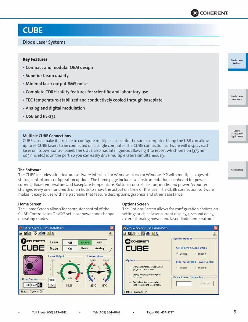
CUBEDiode Laser Systems
CUBE™ lasers are high-performance, full-feature diodelaser systems. Each contains a laser head, power supply,cable, and control box. The system is designed to beone of the easiest to set-up and use. The CUBE deliversthe most power, stability and performance—in thesmallest package—with the best value.
A complete systemAll CUBE electronics, optics and thermal managementare built into the head. Every system includes a full-feature cable that lets you access all the features insidethe CUBE. A compact 6V power supply, a control box forsafety features, and USB software to drive the laser arealso included.
The CUBEThe CUBE offers you full control. First, the CUBE canwork as a CW laser with a convenient auto-start mode.The CUBE also offers a digital input connector, locatedon the back panel, to drive the laser up to 150 MHz witha TTL source. Users can then command the CUBE tochange the power level, either through the RS-232 orUSB. For analog modulation the CUBE offers a separateanalog input, located on the front panel of the controlbox, which allows variable power control up to 350 kHz.
For high dynamic range the digital modulation andanalog power controls offer modulation depths greaterthan 250:1. For maximum flexibility in your applicationthe CUBE also offers mode selection for constant- power or constant-current drive. The versatility of theCUBE includes CW, digital control, analog control andvariable power operation.
With all the electronics inside the head, the control and instrumentation are available through the 15-pinconnector on the laser’s back panel. The interlock input,laser enable input, or auto-start mode provide control.Instrumentation on the CUBE gives you a laser-readyoutput, laser output power (actual laser power in ananalog signal), baseplate temperature and general fault conditions. Every CUBE laser has a built-in photo-diode that measures the laser final output power. Thephotodiode enables closed-loop power stability andallows you to know the laser power via the analogoutput or computer. CUBE lasers are also equippedwith dual-temperature probes, which control thermalmanagement and display both the diode and baseplatetemperature. Overall, the CUBE offers complete controland instrumentation without the need for additionalequipment.
Diode Laser Systems
Diode Laser Modules
Lasiris Structured
Light Lasers
Accessories
• Toll Free: (800) 343-4912 • Tel: (408) 764-4042 • Fax: (503) 454-5727 9
CUBEDiode Laser Systems
Home ScreenThe Home Screen allows for computer control of theCUBE. Control laser On/Off, set laser power and changeoperating modes.
The SoftwareThe CUBE includes a full-feature software interface for Windows 2000 or Windows XP with multiple pages of status, control and configuration options. The home page includes an instrumentation dashboard for power, current, diode temperature and baseplate temperature. Buttons control laser on, mode, and power. A counter changes every one hundredth of an hour to show the actual ‘on’ time of the laser. The CUBE connection software makes it easy to use with help screens that feature descriptions, graphics and other assistance.
Options ScreenThe Options Screen allows for configuration choices onsettings such as laser current display, 5-second delay,external analog power and laser diode temperature.
Multiple CUBE ConnectionsCUBE lasers make it possible to configure multiple lasers into the same computer. Using the USB can allow up to 16 CUBE lasers to be connected on a single computer. The CUBE connection software will display each laser on its own control panel. The CUBE also has intelligence, allowing it to report which version (375 nm, 405 nm, etc.) is on the port, so you can easily drive multiple lasers simultaneously.
Diode Laser Systems
Diode Laser Modules
Lasiris Structured
Light Lasers
Accessories
Key Features
• Compact and modular OEM design
• Superior beam quality
• Minimal laser output RMS noise
• Complete CDRH safety features for scientific and laboratory use
• TEC temperature-stabilized and conductively cooled through baseplate
• Analog and digital modulation
• USB and RS-232

Superior Reliability & Performance • www.Coherent.com • [email protected]
CUBEDiode Laser Systems
Terminal ScreenThe Terminal Screen allows for direct communication to the CUBE through the command line. Scripts can also be executed and set to loop. The Terminal Screen can accelerate the learning curve for laser control in embedded applications.
Status ScreenThe Status Screen shows the details of the laser fromserial number to operating hours. A separate FaultScreen also shows any faults from an interlock fault toover-temperature.
The Control BoxTo comply with the CDRH safety requirements for a Class IIIb laser, the CUBE includes both the shutter on the front of the laser and a separate control box. The control box includes the key switch that activates the laser, a five-second power-on delay, an interlock RCA jack on the back panel and a laser emission indicator. (For countries requiring a second laser emission indicator, a second lamp that connects to the cable I/O connector can be purchased separately [part no. 1079150].) The control box also offers a front panel BNC connection for the analog power control, which can use an external voltage source (0-5V) to change the CUBE’s output power.
The CableThe CUBE’s full-feature cable allows access and control to all its capabilities. The cable offers four separate lines: for power, I/O, control box, and RS-232. The I/O cable is labeled with the signal’s name, pin number, and description so you can easily connect to the eight (8) separate laser control/instrumentation signals. For example, connect a voltmeter between pin numbers 2 and 7 and instantly the meter is now reporting laser power with 2V equivalent to 100% laser output power. Or connect the convenient Second Emission Lamp [part no. 1079150] as an additional safety measure.
The RS-232 cable can plug the laser directly into a computer for remote control and instrumentation.
The control box is conveniently connected to allow required safety features and analog power control from the front panel BNC. Also included with each CUBE is a USB cable, which allows the laser to plug directly into any Windows* 2000 or Windows XP system.
The Power SupplyThe CUBE, which has been designed for easy integration into your system with a single power supply input, can accept from 4.8V to 6.5VDC.
Control and I/OCUBE systems offer an extensive list of commands that can be executed through the RS-232 or USB. Please visit www.coherent.com and download the CUBE User Manual or the CUBE help screens for a full description of the commands and I/O.
Diode Laser Systems
Diode Laser Modules
Lasiris Structured
Light Lasers
Accessories

• Toll Free: (800) 343-4912 • Tel: (408) 764-4042 • Fax: (503) 454-5727 11
CUBEDiode Laser Systems
Every CUBE system comes standard with a compact 6VDC supply with a power switch and an LED. The power supply is equipped with an IEC320 universal input, which allows most computer-style power cords to be easily used with your country’s power (U.S. -style power cord is included).
ReliabilityThe CUBE is fully protected from electro-static dis-charge (ESD) to Level 4 standards and is also equipped with temperate shutdown systems to protect the laser diode. The diode and optics are temperature-controlled through a TEC to provide the optimal performance and maximum lifetime. Reliability is the priority—within every CUBE is a computer processor controlling all the aspects of the laser drive, thermal systems and protection measures.
The ExtrasFor even simpler set-up and integration, a heat sinkaccessory provides a convenient 2.5” beam height and a universal bolt pattern for easy mounting—with thebeam axis traveling directly down a row of holes on the laser table. For high-temperature applications a fan inside the heat sink provides additional cooling. Please note that the CUBE comes standard with the laser head, control box, cables, power supply, manual,software, and a U.S. power cord. The heat sink, however,is sold separately.
Overall, CUBE lasers can give you more powerful and efficient ways to use diode laser light in the fields of bioinstrumentation, particle counting, confocalmicroscopy, high-throughput screening, or generallaboratory work.
Diode Laser Systems
Diode Laser Modules
Lasiris Structured
Light Lasers
Accessories

Superior Reliability & Performance • www.Coherent.com • [email protected]
CUBEDiode Laser Systems
CUBE 375-16C 405-50C 405-100CPart Number 1112774 1174298 1142279Wavelength1 (nm) 375 405 405Output Power2 (mW) 16 50 100Beam Diameter at 1/e2 (mm)(typical) 1.1 1.4 1.4Beam Divergence (mrad)(typical) 0.5 0.4 0.4M2 (ModeMaster beam quality)3 <_1.3 <_1.3 <_1.2Beam Asymmetry3 <1:1.2Laser Drive Modes Digital, Analog and PC ControlDigital Modulation Maximum Bandwidth (MHz) 150 Rise Time (10% to 90%) (nsec) <2 Fall Time (10% to 90%) (nsec) <2 Modulation Depth (extinction ratio) >1,000,000:1 at 0 Hz, >250:1 at 150 MHzAnalog Modulation Maximum Bandwidth (kHz) 70 350 350 Rise or Fall Time (10% to 90%) (μsec) <5 <1 <1 Modulation Depth (extinction ratio) >10,000:1Laser Enable Control Input Maximum Bandwidth (kHz) 130 Rise or Fall Time (10% to 90%) (μsec) <1 Modulation Depth (extinction ratio) ∞, complete On/OffRMS Noise 20 Hz to 10 MHz <_0.15% <_0.1% 10 MHz to 500 MHz <1.0%Long-Term Power Stability (8 hours) <±2%Warm-Up Time (minutes) <5Spatial Mode (far field) TEMooPointing Stability (μrad/°C) <6Polarization Ratio4 Min. 100:1, Vert. ±5°Static Alignment Tolerances5
Beam Position (mm) <1 Beam Angle (mrad) <5CDRH Laser Classification Class IIIbESD Protection6 Level 4
SystemSpecificationsDiode Laser
Systems
Diode Laser Modules
Lasiris Structured
Light Lasers
Accessories
1 Laser-to-laser tolerance. All lasers ±5 nm except CUBE 640-40 with 635 to 642 nm range, CUBE 640-100 with 635 to 644 nm range, CUBE 660 with 652 to 665 nm range, and CUBE 685, 730 and 785 with ±10 nm.2 Output power is variable via RS-232, USB or analog interface from 1% to 100%. Specifications are valid for 100% power. Recommended power range is 70% to 100% power.3 M2 and Beam Asymmetry measured with ModeMaster with 90/10 clip levels.4 Polarization measurement is max./min. power with polarizer at 32 in. from laser with LM-2 power head at 37 in. from laser.5 Static alignment tolerances are relative to the right bottom edge (in beam direction).6 Electro-Static Discharge Standard IEC 1000-4-2, 1995.
• Toll Free: (800) 343-4912 • Tel: (408) 764-4042 • Fax: (503) 454-5727 13
CUBEDiode Laser Systems
SystemSpecifications
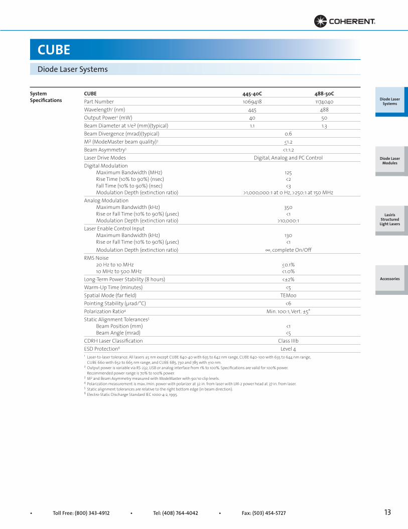
CUBE 445-40C 488-50CPart Number 1069418 1174040Wavelength1 (nm) 445 488Output Power2 (mW) 40 50Beam Diameter at 1/e2 (mm)(typical) 1.1 1.3Beam Divergence (mrad)(typical) 0.6M2 (ModeMaster beam quality)3 <_1.2Beam Asymmetry3 <1:1.2Laser Drive Modes Digital, Analog and PC ControlDigital Modulation Maximum Bandwidth (MHz) 125 Rise Time (10% to 90%) (nsec) <2 Fall Time (10% to 90%) (nsec) <3 Modulation Depth (extinction ratio) >1,000,000:1 at 0 Hz, >250:1 at 150 MHzAnalog Modulation Maximum Bandwidth (kHz) 350 Rise or Fall Time (10% to 90%) (μsec) <1 Modulation Depth (extinction ratio) >10,000:1Laser Enable Control Input Maximum Bandwidth (kHz) 130 Rise or Fall Time (10% to 90%) (μsec) <1 Modulation Depth (extinction ratio) ∞, complete On/OffRMS Noise 20 Hz to 10 MHz <_0.1% 10 MHz to 500 MHz <1.0%Long-Term Power Stability (8 hours) <±2%Warm-Up Time (minutes) <5Spatial Mode (far field) TEMooPointing Stability (μrad/°C) <6Polarization Ratio4 Min. 100:1, Vert. ±5°Static Alignment Tolerances5
Beam Position (mm) <1 Beam Angle (mrad) <5CDRH Laser Classification Class IIIbESD Protection6 Level 4
Diode Laser Systems
Diode Laser Modules
Lasiris Structured
Light Lasers
Accessories
1 Laser-to-laser tolerance. All lasers ±5 nm except CUBE 640-40 with 635 to 642 nm range, CUBE 640-100 with 635 to 644 nm range, CUBE 660 with 652 to 665 nm range, and CUBE 685, 730 and 785 with ±10 nm.2 Output power is variable via RS-232, USB or analog interface from 1% to 100%. Specifications are valid for 100% power. Recommended power range is 70% to 100% power.3 M2 and Beam Asymmetry measured with ModeMaster with 90/10 clip levels.4 Polarization measurement is max./min. power with polarizer at 32 in. from laser with LM-2 power head at 37 in. from laser.5 Static alignment tolerances are relative to the right bottom edge (in beam direction).6 Electro-Static Discharge Standard IEC 1000-4-2, 1995.
Superior Reliability & Performance • www.Coherent.com • [email protected]
CUBEDiode Laser Systems
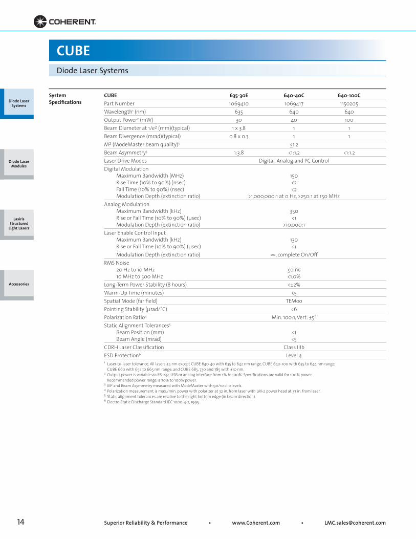
CUBE 635-30E 640-40C 640-100CPart Number 1069410 1069417 1150205Wavelength1 (nm) 635 640 640Output Power2 (mW) 30 40 100Beam Diameter at 1/e2 (mm)(typical) 1 x 3.8 1 1Beam Divergence (mrad)(typical) 0.8 x 0.3 1 1M2 (ModeMaster beam quality)3 <_1.2Beam Asymmetry3 1:3.8 <1:1.2 <1:1.2Laser Drive Modes Digital, Analog and PC ControlDigital Modulation Maximum Bandwidth (MHz) 150 Rise Time (10% to 90%) (nsec) <2 Fall Time (10% to 90%) (nsec) <2 Modulation Depth (extinction ratio) >1,000,000:1 at 0 Hz, >250:1 at 150 MHzAnalog Modulation Maximum Bandwidth (kHz) 350 Rise or Fall Time (10% to 90%) (μsec) <1 Modulation Depth (extinction ratio) >10,000:1Laser Enable Control Input Maximum Bandwidth (kHz) 130 Rise or Fall Time (10% to 90%) (μsec) <1 Modulation Depth (extinction ratio) ∞, complete On/OffRMS Noise 20 Hz to 10 MHz <_0.1% 10 MHz to 500 MHz <1.0%Long-Term Power Stability (8 hours) <±2%Warm-Up Time (minutes) <5Spatial Mode (far field) TEMooPointing Stability (μrad/°C) <6Polarization Ratio4 Min. 100:1, Vert. ±5°Static Alignment Tolerances5
Beam Position (mm) <1 Beam Angle (mrad) <5CDRH Laser Classification Class IIIbESD Protection6 Level 4
SystemSpecifications
1 Laser-to-laser tolerance. All lasers ±5 nm except CUBE 640-40 with 635 to 642 nm range, CUBE 640-100 with 635 to 644 nm range, CUBE 660 with 652 to 665 nm range, and CUBE 685, 730 and 785 with ±10 nm.2 Output power is variable via RS-232, USB or analog interface from 1% to 100%. Specifications are valid for 100% power. Recommended power range is 70% to 100% power.3 M2 and Beam Asymmetry measured with ModeMaster with 90/10 clip levels.4 Polarization measurement is max./min. power with polarizer at 32 in. from laser with LM-2 power head at 37 in. from laser.5 Static alignment tolerances are relative to the right bottom edge (in beam direction).6 Electro-Static Discharge Standard IEC 1000-4-2, 1995.
Diode Laser Systems
Diode Laser Modules
Lasiris Structured
Light Lasers
Accessories

• Toll Free: (800) 343-4912 • Tel: (408) 764-4042 • Fax: (503) 454-5727 15
CUBEDiode Laser Systems
CUBE 660-60C 660-100C 685-40CPart Number 1094060 1130061 1184303Wavelength1 (nm) 660 660 685Output Power2 (mW) 60 100 40Beam Diameter at 1/e2 (mm)(typical) 1.4 1 1Beam Divergence (mrad)(typical) 0.6 1 1M2 (ModeMaster beam quality)3 <_1.2Beam Asymmetry3 <1:1.2Laser Drive Modes Digital, Analog and PC ControlDigital Modulation Maximum Bandwidth (MHz) 150 150 150 Rise Time (10% to 90%) (nsec) <2 <2 <2 Fall Time (10% to 90%) (nsec) <2 <2 <2 Modulation Depth (extinction ratio) >1,000,000:1 at 0 Hz, >250:1 at 150 MHzAnalog Modulation Maximum Bandwidth (kHz) 350 Rise or Fall Time (10% to 90%) (μsec) <1 Modulation Depth (extinction ratio) >10,000:1Laser Enable Control Input Maximum Bandwidth (kHz) 130 Rise or Fall Time (10% to 90%) (μsec) <1 Modulation Depth (extinction ratio) ∞, complete On/OffRMS Noise 20 Hz to 10 MHz <_0.1% 10 MHz to 500 MHz <1.0%Long-Term Power Stability (8 hours) <±2%Warm-Up Time (minutes) <5Spatial Mode (far field) TEMooPointing Stability (μrad/°C) <6Polarization Ratio4 Min. 100:1, Vert. ±5°Static Alignment Tolerances5
Beam Position (mm) <1 Beam Angle (mrad) <5CDRH Laser Classification Class IIIbESD Protection6 Level 4
SystemSpecifications
1 Laser-to-laser tolerance. All lasers ±5 nm except CUBE 640-40 with 635 to 642 nm range, CUBE 640-100 with 635 to 644 nm range, CUBE 660 with 652 to 665 nm range, and CUBE 685, 730 and 785 with ±10 nm.2 Output power is variable via RS-232, USB or analog interface from 1% to 100%. Specifications are valid for 100% power. Recommended power range is 70% to 100% power.3 M2 and Beam Asymmetry measured with ModeMaster with 90/10 clip levels.4 Polarization measurement is max./min. power with polarizer at 32 in. from laser with LM-2 power head at 37 in. from laser.5 Static alignment tolerances are relative to the right bottom edge (in beam direction).6 Electro-Static Discharge Standard IEC 1000-4-2, 1995.
Diode Laser Systems
Diode Laser Modules
Lasiris Structured
Light Lasers
Accessories
Superior Reliability & Performance • www.Coherent.com • [email protected]
CUBEDiode Laser Systems
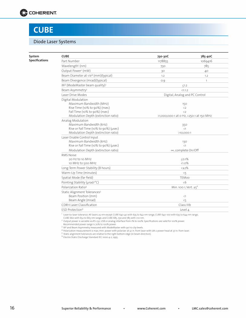
CUBE 730-30C 785-40CPart Number 1178855 1069416Wavelength1 (nm) 730 785Output Power2 (mW) 30 40Beam Diameter at 1/e2 (mm)(typical) 1.2 1.2Beam Divergence (mrad)(typical) 0.9 1M2 (ModeMaster beam quality)3 <_1.2Beam Asymmetry3 <1:1.2Laser Drive Modes Digital, Analog and PC ControlDigital Modulation Maximum Bandwidth (MHz) 150 Rise Time (10% to 90%) (nsec) <2 Fall Time (10% to 90%) (nsec) <2 Modulation Depth (extinction ratio) >1,000,000:1 at 0 Hz, >250:1 at 150 MHzAnalog Modulation Maximum Bandwidth (kHz) 350 Rise or Fall Time (10% to 90%) (μsec) <1 Modulation Depth (extinction ratio) >10,000:1Laser Enable Control Input Maximum Bandwidth (kHz) 130 Rise or Fall Time (10% to 90%) (μsec) <1 Modulation Depth (extinction ratio) ∞, complete On/OffRMS Noise 20 Hz to 10 MHz <_0.1% 10 MHz to 500 MHz <1.0%Long-Term Power Stability (8 hours) <±2%Warm-Up Time (minutes) <5Spatial Mode (far field) TEMooPointing Stability (μrad/°C) <6Polarization Ratio4 Min. 100:1, Vert. ±5°Static Alignment Tolerances5
Beam Position (mm) <1 Beam Angle (mrad) <5CDRH Laser Classification Class IIIbESD Protection6 Level 4
SystemSpecifications
1 Laser-to-laser tolerance. All lasers ±5 nm except CUBE 640-40 with 635 to 642 nm range, CUBE 640-100 with 635 to 644 nm range, CUBE 660 with 652 to 665 nm range, and CUBE 685, 730 and 785 with ±10 nm.2 Output power is variable via RS-232, USB or analog interface from 1% to 100%. Specifications are valid for 100% power. Recommended power range is 70% to 100% power.3 M2 and Beam Asymmetry measured with ModeMaster with 90/10 clip levels.4 Polarization measurement is max./min. power with polarizer at 32 in. from laser with LM-2 power head at 37 in. from laser.5 Static alignment tolerances are relative to the right bottom edge (in beam direction).6 Electro-Static Discharge Standard IEC 1000-4-2, 1995.
• Toll Free: (800) 343-4912 • Tel: (408) 764-4042 • Fax: (503) 454-5727 17
CUBEDiode Laser Systems
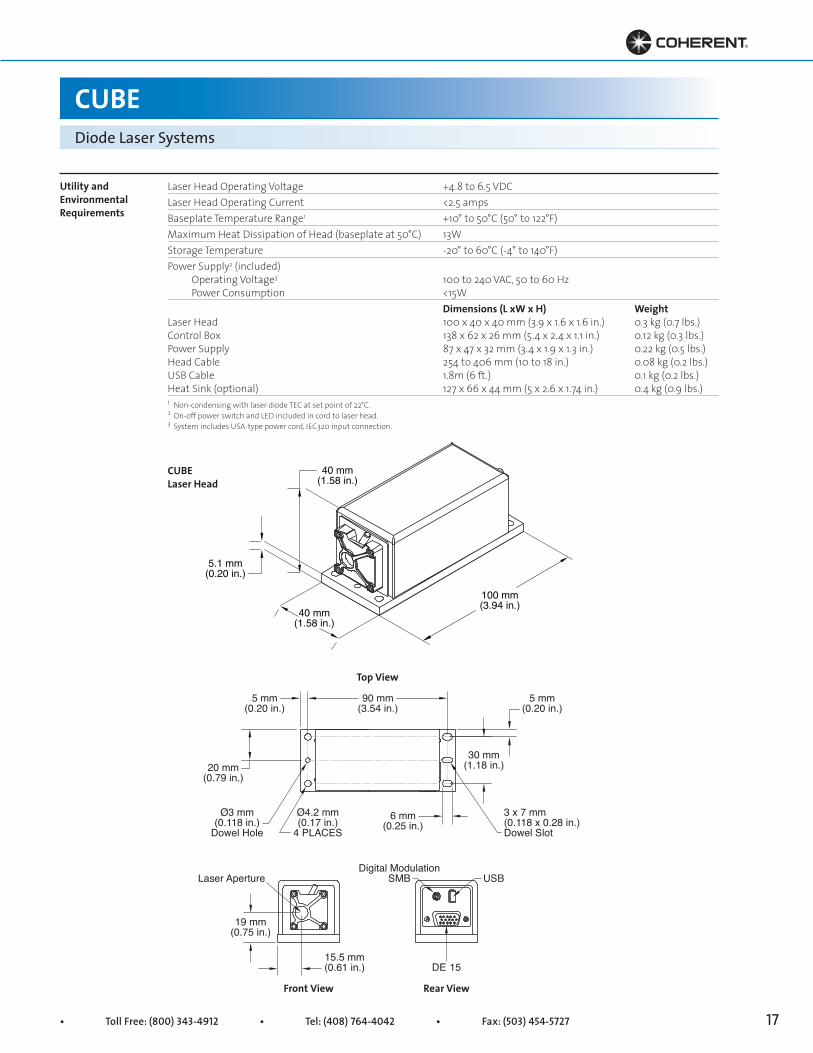
Laser Head Operating Voltage +4.8 to 6.5 VDCLaser Head Operating Current <2.5 ampsBaseplate Temperature Range1 +10° to 50°C (50° to 122°F)Maximum Heat Dissipation of Head (baseplate at 50°C) 13WStorage Temperature -20° to 60°C (-4° to 140°F)Power Supply2 (included) Operating Voltage3 100 to 240 VAC, 50 to 60 Hz Power Consumption <15W Dimensions (L xW x H) WeightLaser Head 100 x 40 x 40 mm (3.9 x 1.6 x 1.6 in.) 0.3 kg (0.7 lbs.)Control Box 138 x 62 x 26 mm (5.4 x 2.4 x 1.1 in.) 0.12 kg (0.3 lbs.)Power Supply 87 x 47 x 32 mm (3.4 x 1.9 x 1.3 in.) 0.22 kg (0.5 lbs.)Head Cable 254 to 406 mm (10 to 18 in.) 0.08 kg (0.2 lbs.)USB Cable 1.8m (6 ft.) 0.1 kg (0.2 lbs.)Heat Sink (optional) 127 x 66 x 44 mm (5 x 2.6 x 1.74 in.) 0.4 kg (0.9 lbs.)1 Non-condensing with laser diode TEC at set point of 22°C.2 On-off power switch and LED included in cord to laser head.3 System includes USA-type power cord, IEC320 input connection.
CUBE Laser Head
Utility and EnvironmentalRequirements
30 mm(1.18 in.)20 mm
(0.79 in.)
5 mm(0.20 in.)
6 mm(0.25 in.)
90 mm(3.54 in.)
Ø4.2 mm(0.17 in.)
4 PLACES
Ø3 mm(0.118 in.)
Dowel Hole
Laser Aperture USB
DE 15
Digital ModulationSMB
3 x 7 mm(0.118 x 0.28 in.)Dowel Slot
5 mm(0.20 in.)
19 mm(0.75 in.)
15.5 mm(0.61 in.)
40 mm(1.58 in.)
40 mm(1.58 in.)
100 mm(3.94 in.)
5.1 mm(0.20 in.)
Top View
Front View Rear View
Superior Reliability & Performance • www.Coherent.com • [email protected]
CUBEDiode Laser Systems
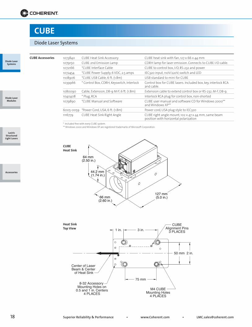
1073840 CUBE Heat Sink Accessory CUBE heat sink with fan, 127 x 66 x 44 mm1079150 CUBE 2nd Emission Lamp CDRH lamp for laser emission. Connects to CUBE I/O cable.1072166 *CUBE Interface Cable CUBE to control box, I/O, RS-232 and power1072454 *CUBE Power Supply, 6 VDC, 2.5 amps IEC320 input, 110V/220V, switch and LED1108906 *CUBE USB Cable, 6 ft. (1.8m) USB standard to mini for CUBE1039966 * Control Box, CDRH, Keyswitch, Interlock Control box for CUBE lasers. Included box, key, interlock RCA and cable.1080090 Cable, Extension, DB-9 M/F, 6 ft. (1.8m) Extension cable to extend control box or RS-232. M-F, DB-9.1040408 * Plug, RCA Interlock RCA plug for control box, non-shorted1079890 *CUBE Manual and Software CUBE user manual and software CD for Windows 2000** and Windows XP**6005-0059 *Power Cord, USA, 6 ft. (1.8m) Power cord, USA plug style to IEC3201116779 CUBE Heat Sink Right Angle CUBE right angle mount, 102 x 47 x 44 mm, same beam position with horizontal polarization
CUBE Accessories
* Included free with every CUBE system. ** Windows 2000 and Windows XP are registered trademarks of Microsoft Corporation.
CUBE Heat Sink
Heat SinkTop View
Diode Laser Systems
Diode Laser Modules
Lasiris Structured
Light Lasers
Accessories
Center of Laser Beam & Center
of Heat Sink
8-32 Accessory Mounting Holes on
0.5 and 1 in. Centers4 PLACES
M4 CUBEMounting Holes
4 PLACES
CUBEAlignment Pins
3 PLACES
75 mm
50 mm 2 in.
1 in. 3 in.
64 mm (2.50 in.)
66 mm (2.60 in.)
127 mm (5.0 in.)
44.2 mm (1.74 in.)

• Toll Free: (800) 343-4912 • Tel: (408) 764-4042 • Fax: (503) 454-5727 19
47 mm (1.85 in.)
Analog Control Input
BNC
86.5 mm (3.41 in.)
Interlock RCA Connection
32 mm(1.26 in.)
26 mm(1.0 in.)
138 mm(5.4 in.)62 mm
(2.4 in.)
~280 mm Cord(11.0 in.)
~1.8 m Cord(6 ft.)
CUBEDiode Laser Systems
CUBE Power Supply
CUBEControl Box
Diode Laser Systems
Diode Laser Modules
Lasiris Structured
Light Lasers
Accessories
Superior Reliability & Performance • www.Coherent.com • [email protected]
USB
1000 mm(39 in.)
40 mm(1.58 in.)
40 mm(1.58 in.)
5.1 mm(0.2 in.)
100 mm(3.94 in.)
50 mm(1.97 in.)
1000 mm(39 in.)
90 mm(3.54 in.)
5 mm(0.2 in.)
30 mm(1.18 in.)
6 mm(0.24 in.)
12 mm(0.47 in.)
Stainless Steel Jacket
3 x 7 mm(0.118 x 0.28 in.)
Dowel SlotØ4.2 mm(0.17 in.)3 Places
(0.25 in.)
5 mm(0.2 in.)
DE-15
Digital ModulationSMB
FC Connector Key
Polish DirectionAxis ±4° Max.
Vertical Polarization±2° Max.
View of Fiber from Connector End
Scale 2:1
Angle Polished 8 ±0.5°
C.20 ±0.10
8.0°3 mm PVC Furcation Tubing
FC Connector KeyType R - Narrow Key(2.0 +0.02/-0.03 Key Width)
8.0°
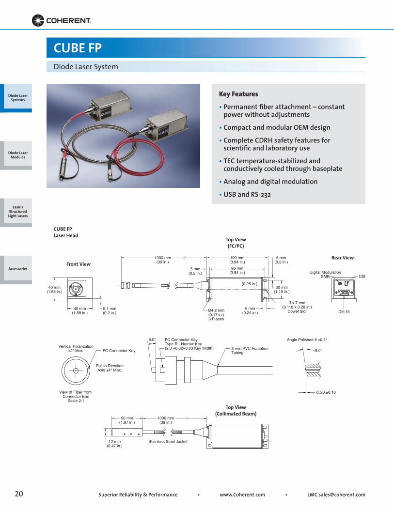
CUBE FPDiode Laser System
Key Features
• Permanent fiber attachment – constant power without adjustments
• Compact and modular OEM design
• Complete CDRH safety features for scientific and laboratory use
• TEC temperature-stabilized and conductively cooled through baseplate
• Analog and digital modulation
• USB and RS-232
Front ViewRear View
Top View(FC/PC)
Top View(Collimated Beam)
CUBE FP Laser Head
Diode Laser Systems
Diode Laser Modules
Lasiris Structured
Light Lasers
Accessories
• Toll Free: (800) 343-4912 • Tel: (408) 764-4042 • Fax: (503) 454-5727 21
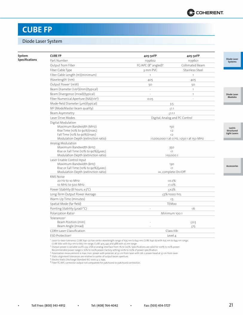
CUBE FP 405-50FP 405-50FPPart Number 1139602 1139601Output from Fiber FC/APC (8° angled)6 Collimated BeamFiber Cable Type 3 mm PVC Stainless SteelFiber Cable Length (m)(minimum) 1 1Wavelength1 (nm) 405 405Output Power2 (mW) 50 50Beam Diameter (1/e2)(mm)(typical) - 1Beam Divergence (mrad)(typical) - 1Fiber Numerical Aperture (NA)(1/e2) 0.05 -Mode-field Diameter (μm)(typical) 3.5M2 (ModeMaster beam quality) <_1.1Beam Asymmetry <_1:1.1Laser Drive Modes Digital, Analog and PC ControlDigital Modulation Maximum Bandwidth (MHz) 150 Rise Time (10% to 90%)(nsec) <2 Fall Time (10% to 90%)(nsec) <2 Modulation Depth (extinction ratio) >1,000,000:1 at 0 Hz, >250:1 at 150 MHzAnalog Modulation Maximum Bandwidth (kHz) 350 Rise or Fall Time (10% to 90%)(μsec) <1 Modulation Depth (extinction ratio) >10,000:1Laser Enable Control Input Maximum Bandwidth (kHz) 130 Rise or Fall Time (10% to 90%)(μsec) <1 Modulation Depth (extinction ratio) ∞, complete On/OffRMS Noise 20 Hz to 10 MHz <0.2% 10 MHz to 500 MHz <1.0%Power Stability (8 hours, ±3°C) <_±2%Long-Term Output Power Average <_5%/1000 hrs.Warm-Up Time (minutes) <5Spatial Mode (far field) TEMooPointing Stability (μrad/°C) - <6Polarization Ratio3 Minimum 100:1Tolerances4
Beam Position (mm) - <_0.5 Beam Angle (mrad) - <_15CDRH Laser Classification Class IIIbESD Protection5 Level 4
CUBE FPDiode Laser System
1 Laser-to-laser tolerance. CUBE 640-30 has center wavelength range of 635 nm to 642 nm, CUBE 640-75 with 635 nm to 644 nm range, CUBE 660 with 652 nm to 665 nm range, CUBE 405, 445 and 488 with ±5 nm range.2 Output power is variable via RS-232, USB or analog interface from 1% to 100%. Specifications are valid for 100% to 110% power. Recommended power range is 70% to 100% power. Factory setting 100% to 110% of power specification.3 Polarization measurement is max./min. power with polarizer at 32 cm from laser with LM-2 power head at 37 cm from laser.4 Static alignment tolerances are relative to center of output beam aperture.5 Electro-Static Discharge Standard IEC 1000-4-2, 1995.6 Fiber FC/APC connector output not compatible for patchcord-to-patchcord connection.
Diode Laser Systems
Diode Laser Modules
Lasiris Structured
Light Lasers
Accessories
SystemSpecifications
Superior Reliability & Performance • www.Coherent.com • [email protected]
Diode Laser Systems
Diode Laser Modules
Lasiris Structured
Light Lasers
Accessories
CUBE FPDiode Laser System
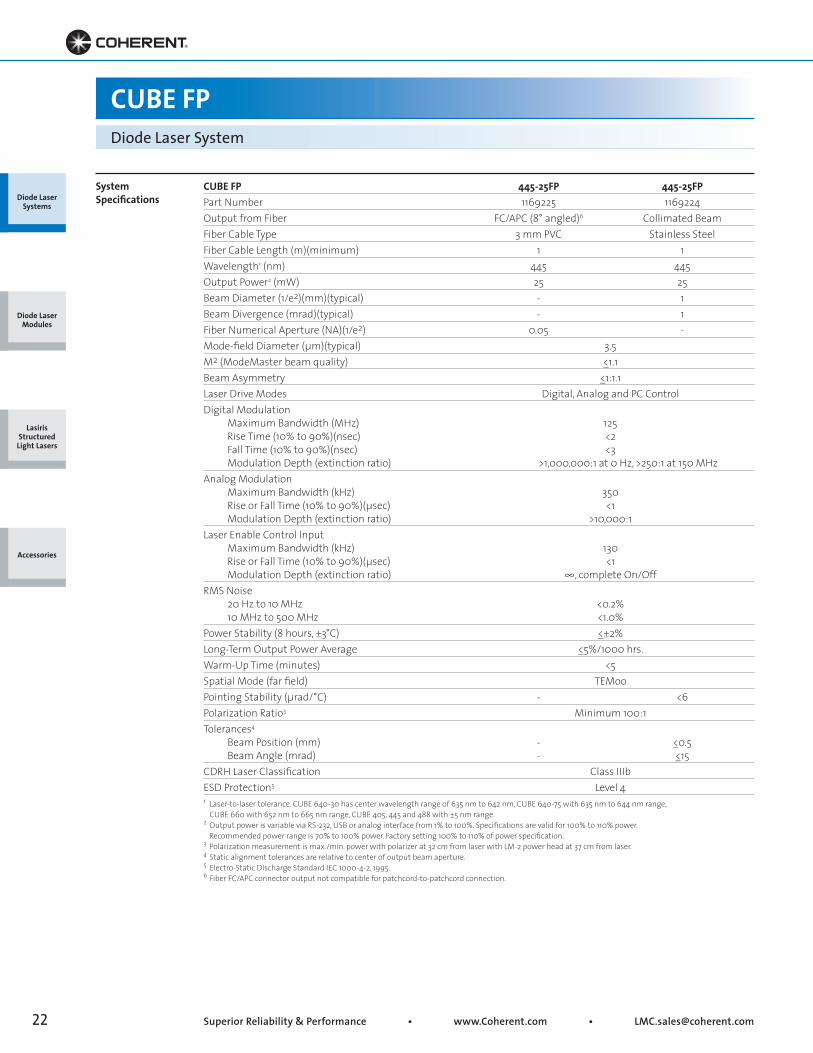
CUBE FP 445-25FP 445-25FPPart Number 1169225 1169224Output from Fiber FC/APC (8° angled)6 Collimated BeamFiber Cable Type 3 mm PVC Stainless SteelFiber Cable Length (m)(minimum) 1 1Wavelength1 (nm) 445 445Output Power2 (mW) 25 25Beam Diameter (1/e2)(mm)(typical) - 1Beam Divergence (mrad)(typical) - 1Fiber Numerical Aperture (NA)(1/e2) 0.05 -Mode-field Diameter (μm)(typical) 3.5M2 (ModeMaster beam quality) <_1.1Beam Asymmetry <_1:1.1Laser Drive Modes Digital, Analog and PC ControlDigital Modulation Maximum Bandwidth (MHz) 125 Rise Time (10% to 90%)(nsec) <2 Fall Time (10% to 90%)(nsec) <3 Modulation Depth (extinction ratio) >1,000,000:1 at 0 Hz, >250:1 at 150 MHzAnalog Modulation Maximum Bandwidth (kHz) 350 Rise or Fall Time (10% to 90%)(μsec) <1 Modulation Depth (extinction ratio) >10,000:1Laser Enable Control Input Maximum Bandwidth (kHz) 130 Rise or Fall Time (10% to 90%)(μsec) <1 Modulation Depth (extinction ratio) ∞, complete On/OffRMS Noise 20 Hz to 10 MHz <0.2% 10 MHz to 500 MHz <1.0%Power Stability (8 hours, ±3°C) <_±2%Long-Term Output Power Average <_5%/1000 hrs.Warm-Up Time (minutes) <5Spatial Mode (far field) TEMooPointing Stability (μrad/°C) - <6Polarization Ratio3 Minimum 100:1Tolerances4
Beam Position (mm) - <_0.5 Beam Angle (mrad) - <_15CDRH Laser Classification Class IIIbESD Protection5 Level 41 Laser-to-laser tolerance. CUBE 640-30 has center wavelength range of 635 nm to 642 nm, CUBE 640-75 with 635 nm to 644 nm range, CUBE 660 with 652 nm to 665 nm range, CUBE 405, 445 and 488 with ±5 nm range.2 Output power is variable via RS-232, USB or analog interface from 1% to 100%. Specifications are valid for 100% to 110% power. Recommended power range is 70% to 100% power. Factory setting 100% to 110% of power specification.3 Polarization measurement is max./min. power with polarizer at 32 cm from laser with LM-2 power head at 37 cm from laser.4 Static alignment tolerances are relative to center of output beam aperture.5 Electro-Static Discharge Standard IEC 1000-4-2, 1995.6 Fiber FC/APC connector output not compatible for patchcord-to-patchcord connection.
SystemSpecifications

• Toll Free: (800) 343-4912 • Tel: (408) 764-4042 • Fax: (503) 454-5727 23
Diode Laser Systems
Diode Laser Modules
Lasiris Structured
Light Lasers
Accessories
CUBE FPDiode Laser System
CUBE FP 488-30FP 488-30FPPart Number 1169223 1169222Output from Fiber FC/APC (8° angled)6 Collimated BeamFiber Cable Type 3 mm PVC Stainless SteelFiber Cable Length (m)(minimum) 1 1Wavelength1 (nm) 488 488Output Power2 (mW) 30 30Beam Diameter (1/e2)(mm)(typical) - 1Beam Divergence (mrad)(typical) - 1Fiber Numerical Aperture (NA)(1/e2) 0.05 -Mode-field Diameter (μm)(typical) 3.5M2 (ModeMaster beam quality) <_1.1Beam Asymmetry <_1:1.1Laser Drive Modes Digital, Analog and PC ControlDigital Modulation Maximum Bandwidth (MHz) 125 Rise Time (10% to 90%)(nsec) <2 Fall Time (10% to 90%)(nsec) <3 Modulation Depth (extinction ratio) >1,000,000:1 at 0 Hz, >250:1 at 150 MHzAnalog Modulation Maximum Bandwidth (kHz) 350 Rise or Fall Time (10% to 90%)(μsec) <1 Modulation Depth (extinction ratio) >10,000:1Laser Enable Control Input Maximum Bandwidth (kHz) 130 Rise or Fall Time (10% to 90%)(μsec) <1 Modulation Depth (extinction ratio) ∞, complete On/OffRMS Noise 20 Hz to 10 MHz <0.2% 10 MHz to 500 MHz <1.0%Power Stability (8 hours, ±3°C) <_±2%Long-Term Output Power Average <_5%/1000 hrs.Warm-Up Time (minutes) <5Spatial Mode (far field) TEMooPointing Stability (μrad/°C) - <6Polarization Ratio3 Minimum 100:1Tolerances4
Beam Position (mm) - <_0.5 Beam Angle (mrad) - <_15CDRH Laser Classification Class IIIbESD Protection5 Level 41 Laser-to-laser tolerance. CUBE 640-30 has center wavelength range of 635 nm to 642 nm, CUBE 640-75 with 635 nm to 644 nm range, CUBE 660 with 652 nm to 665 nm range, CUBE 405, 445 and 488 with ±5 nm range.2 Output power is variable via RS-232, USB or analog interface from 1% to 100%. Specifications are valid for 100% to 110% power. Recommended power range is 70% to 100% power. Factory setting 100% to 110% of power specification.3 Polarization measurement is max./min. power with polarizer at 32 cm from laser with LM-2 power head at 37 cm from laser.4 Static alignment tolerances are relative to center of output beam aperture.5 Electro-Static Discharge Standard IEC 1000-4-2, 1995.6 Fiber FC/APC connector output not compatible for patchcord-to-patchcord connection.
SystemSpecifications

Superior Reliability & Performance • www.Coherent.com • [email protected]
Diode Laser Systems
Diode Laser Modules
Lasiris Structured
Light Lasers
Accessories
CUBE FPDiode Laser System
Diode Laser Systems
Diode Laser Modules
Lasiris Structured
Light Lasers
Accessories
CUBE FPDiode Laser System
CUBE FP 640-30FP 640-30FP 640-75FP 640-75FPPart Number 1139604 1139603 1169221 1169220Output from Fiber FC/APC (8° angled) Collimated Beam FC/APC (8° angled) Collimated BeamFiber Cable Type 3 mm PVC Stainless Steel 3 mm PVC Stainless SteelFiber Cable Length (m)(minimum) 1 1 1 1Wavelength1 (nm) 640 640 640 640Output Power2 (mW) 30 30 75 75Beam Diameter (1/e2)(mm)(typical) - 1 - 1Beam Divergence (mrad)(typical) - 1 - 1Fiber Numerical Aperture (NA)(1/e2) 0.09 - 0.09 -Mode-field Diameter (μm)(typical) 4.5 - 4.5 -M2 (ModeMaster beam quality) <_1.1Beam Asymmetry <_1:1.1Laser Drive Modes Digital, Analog and PC ControlDigital Modulation Maximum Bandwidth (MHz) 150 Rise Time (10% to 90%)(nsec) <2 Fall Time (10% to 90%)(nsec) <2 Modulation Depth (extinction ratio) >1,000,000:1 at 0 Hz, >250:1 at 150 MHzAnalog Modulation Maximum Bandwidth (kHz) 350 Rise or Fall Time (10% to 90%)(μsec) <1 Modulation Depth (extinction ratio) >10,000:1Laser Enable Control Input Maximum Bandwidth (kHz) 130 Rise or Fall Time (10% to 90%)(μsec) <1 Modulation Depth (extinction ratio) ∞, complete On/OffRMS Noise 20 Hz to 10 MHz <0.2% 10 MHz to 500 MHz <1.0%Power Stability (8 hours, ±3°C) <_±2%Long-Term Output Power Average <_3%/1000 hrs.Warm-Up Time (minutes) <5Spatial Mode (far field) TEMooPointing Stability (μrad/°C) - <6 - <6Polarization Ratio3 Minimum 100:1Tolerances4
Beam Position (mm) - <_0.5 - <_0.5 Beam Angle (mrad) - <_15 - <_15CDRH Laser Classification Class IIIbESD Protection5 Level 41 Laser-to-laser tolerance. CUBE 640-30 has center wavelength range of 635 nm to 642 nm, CUBE 640-75 with 635 nm to 644 nm range, CUBE 660 with 652 nm to 665 nm range, CUBE 405, 445 and 488 with ±5 nm range.2 Output power is variable via RS-232, USB or analog interface from 1% to 100%. Specifications are valid for 100% to 110% power. Recommended power range is 70% to 100% power. Factory setting 100% to 110% of power specification.3 Polarization measurement is max./min. power with polarizer at 32 cm from laser with LM-2 power head at 37 cm from laser.4 Static alignment tolerances are relative to center of output beam aperture.5 Electro-Static Discharge Standard IEC 1000-4-2, 1995.
SystemSpecifications
• Toll Free: (800) 343-4912 • Tel: (408) 764-4042 • Fax: (503) 454-5727 25
Diode Laser Systems
Diode Laser Modules
Lasiris Structured
Light Lasers
Accessories
CUBE FPDiode Laser System
Diode Laser Systems
Diode Laser Modules
Lasiris Structured
Light Lasers
Accessories
CUBE FPDiode Laser System
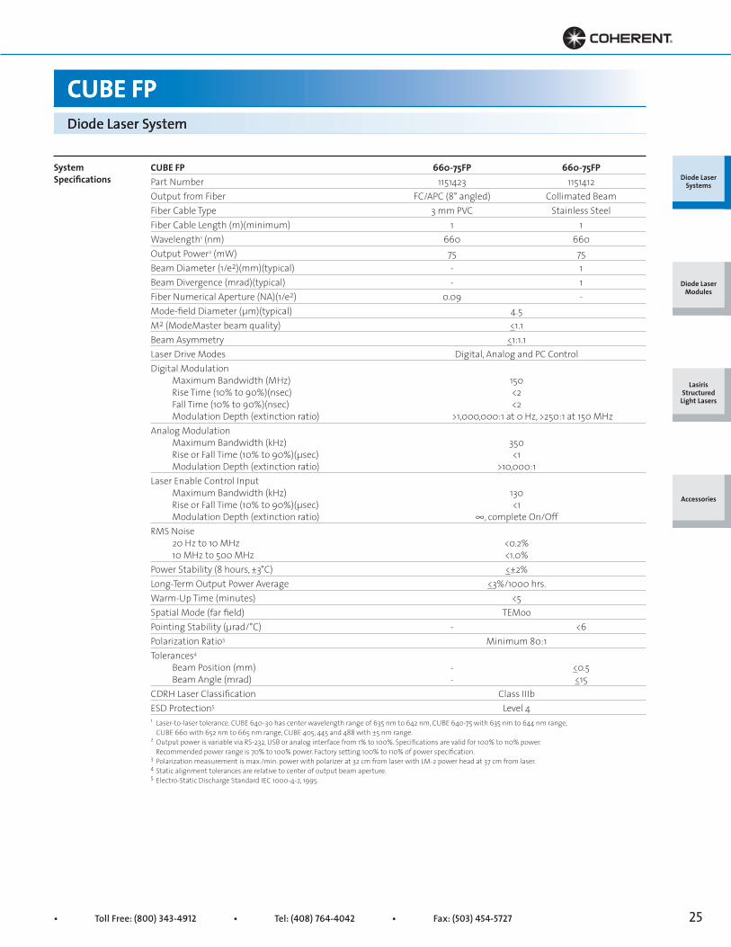
CUBE FP 660-75FP 660-75FPPart Number 1151423 1151412Output from Fiber FC/APC (8° angled) Collimated BeamFiber Cable Type 3 mm PVC Stainless SteelFiber Cable Length (m)(minimum) 1 1Wavelength1 (nm) 660 660Output Power2 (mW) 75 75Beam Diameter (1/e2)(mm)(typical) - 1Beam Divergence (mrad)(typical) - 1Fiber Numerical Aperture (NA)(1/e2) 0.09 -Mode-field Diameter (μm)(typical) 4.5M2 (ModeMaster beam quality) <_1.1Beam Asymmetry <_1:1.1Laser Drive Modes Digital, Analog and PC ControlDigital Modulation Maximum Bandwidth (MHz) 150 Rise Time (10% to 90%)(nsec) <2 Fall Time (10% to 90%)(nsec) <2 Modulation Depth (extinction ratio) >1,000,000:1 at 0 Hz, >250:1 at 150 MHzAnalog Modulation Maximum Bandwidth (kHz) 350 Rise or Fall Time (10% to 90%)(μsec) <1 Modulation Depth (extinction ratio) >10,000:1Laser Enable Control Input Maximum Bandwidth (kHz) 130 Rise or Fall Time (10% to 90%)(μsec) <1 Modulation Depth (extinction ratio) ∞, complete On/OffRMS Noise 20 Hz to 10 MHz <0.2% 10 MHz to 500 MHz <1.0%Power Stability (8 hours, ±3°C) <_±2%Long-Term Output Power Average <_3%/1000 hrs.Warm-Up Time (minutes) <5Spatial Mode (far field) TEMooPointing Stability (μrad/°C) - <6Polarization Ratio3 Minimum 80:1Tolerances4
Beam Position (mm) - <_0.5 Beam Angle (mrad) - <_15CDRH Laser Classification Class IIIbESD Protection5 Level 41 Laser-to-laser tolerance. CUBE 640-30 has center wavelength range of 635 nm to 642 nm, CUBE 640-75 with 635 nm to 644 nm range, CUBE 660 with 652 nm to 665 nm range, CUBE 405, 445 and 488 with ±5 nm range.2 Output power is variable via RS-232, USB or analog interface from 1% to 100%. Specifications are valid for 100% to 110% power. Recommended power range is 70% to 100% power. Factory setting 100% to 110% of power specification.3 Polarization measurement is max./min. power with polarizer at 32 cm from laser with LM-2 power head at 37 cm from laser.4 Static alignment tolerances are relative to center of output beam aperture.5 Electro-Static Discharge Standard IEC 1000-4-2, 1995.
SystemSpecifications

Superior Reliability & Performance • www.Coherent.com • [email protected]
Diode Laser Systems
Diode Laser Modules
Lasiris Structured
Light Lasers
Accessories
CUBE FPDiode Laser System
Laser Head Operating Voltage +4.8 to 6.5 VDCLaser Head Operating Current <2.5 ampsBaseplate Temperature Range1 +10° to 50°C (50° to 122°F)Maximum Heat Dissipation of Head (baseplate at 50°C) 13WStorage Temperature -20° to 60°C (-4° to 140°F)Power Supply2 (included) Operating Voltage3 100 to 240 VAC, 50 to 60 Hz Power Consumption <15W Dimensions (L xW x H) WeightLaser Head 100 x 40 x 40 mm (3.9 x 1.6 x 1.6 in.) 0.3 kg (0.7 lbs.)Laser Head with Minimum Fiber Bend Radius 203 mm (8.0 in.)Fiber Tensile Load (max.) 1 kg (2.2 lbs.)Fiber Minimum Bend Radius 51 mm (2.0 in.)Control Box 138 x 62 x 26 mm (5.4 x 2.4 x 1.1 in.) 0.12 kg (0.3 lbs.)Power Supply 87 x 47 x 32 mm (3.4 x 1.9 x 1.3 in.) 0.22 kg (0.5 lbs.)Head Cable 254 to 406 mm (10 to 18 in.) 0.08 kg (0.2 lbs.)USB Cable 1.8 m (6 ft.) 0.1 kg (0.2 lbs.)Heat Sink (optional - sold separately) 127 x 66 x 44 mm (5 x 2.6 x 1.74 in.) 0.4 kg (0.9 lbs.)1 Non-condensing with laser diode TEC at set point of 22°C.2 On-off power switch and LED included in cord to laser head.3 System includes USA-type power cord, IEC320 input connection.
Utility and EnvironmentalRequirements
• Toll Free: (800) 343-4912 • Tel: (408) 764-4042 • Fax: (503) 454-5727 27
47 mm (1.85 in.)
ut
86.5 mm (3.41 in.)
32 mm(1.26 in.)
~1.8 m Cord(6 ft.)
Analog Control Input
BNC
Interlock RCA Connection
26 mm(1.0 in.)
138 mm(5.4 in.)62 mm
(2.4 in.)
~280 mm Cord(11.0 in.)
8 32 Accessory Mounting Holes on
0.5 and 1 in. Centers4 PLACES
M4 CUBEMounting Holes
3 PLACES
CUBEAlignment Pins
3 PLACES
75 mm
50 mm 2 in.
1 in. 3 in.
66 mm (2.60 in.)
127 mm (5.0 in.)
44.2 mm (1.74 in.)
Diode Laser Systems
Diode Laser Modules
Lasiris Structured
Light Lasers
Accessories
CUBE FPDiode Laser System
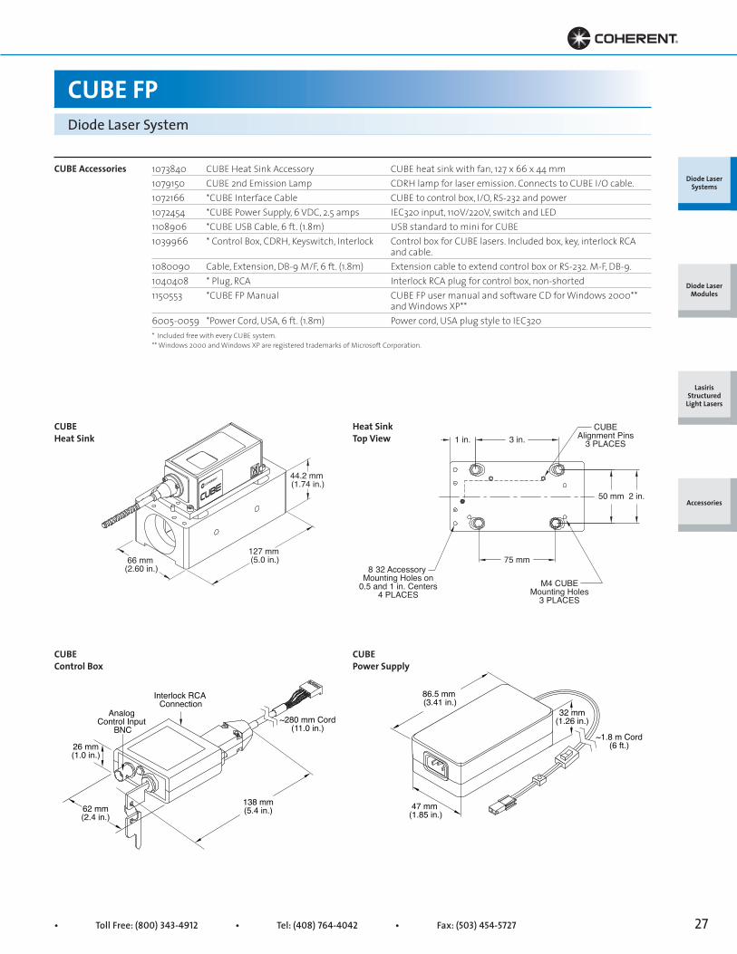
1073840 CUBE Heat Sink Accessory CUBE heat sink with fan, 127 x 66 x 44 mm1079150 CUBE 2nd Emission Lamp CDRH lamp for laser emission. Connects to CUBE I/O cable.1072166 *CUBE Interface Cable CUBE to control box, I/O, RS-232 and power1072454 *CUBE Power Supply, 6 VDC, 2.5 amps IEC320 input, 110V/220V, switch and LED1108906 *CUBE USB Cable, 6 ft. (1.8m) USB standard to mini for CUBE1039966 * Control Box, CDRH, Keyswitch, Interlock Control box for CUBE lasers. Included box, key, interlock RCA and cable.1080090 Cable, Extension, DB-9 M/F, 6 ft. (1.8m) Extension cable to extend control box or RS-232. M-F, DB-9.1040408 * Plug, RCA Interlock RCA plug for control box, non-shorted1150553 *CUBE FP Manual CUBE FP user manual and software CD for Windows 2000** and Windows XP**6005-0059 *Power Cord, USA, 6 ft. (1.8m) Power cord, USA plug style to IEC320
CUBE Accessories
* Included free with every CUBE system. ** Windows 2000 and Windows XP are registered trademarks of Microsoft Corporation.
CUBE Heat Sink
CUBE Control Box
Heat SinkTop View
CUBE Power Supply

Superior Reliability & Performance • www.Coherent.com • [email protected]
RadiusDiode Laser Systems
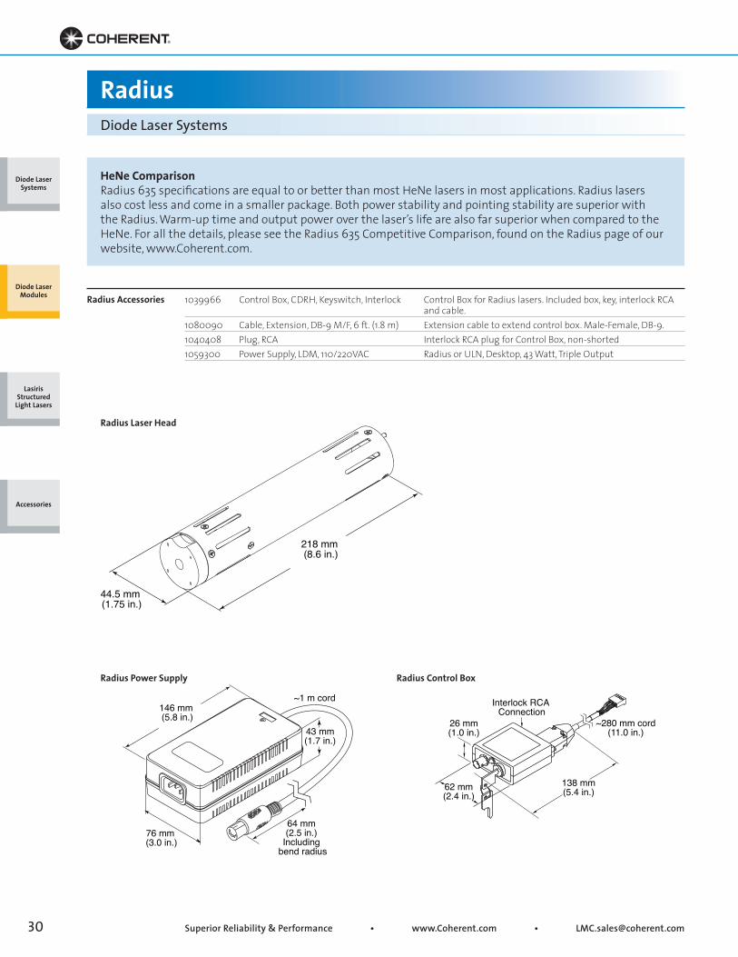
Radius lasers are full-featured, high-performance, CW diode laser systems that include a laser head, power supply and optional control box. Designed for convenient mounting into a HeNe laser holder for fast and simple integration, they deliver power, stability and performance in a complete package with the best value.
Adjustable Focus Radius These lasers allow faster and easier system integra-tion. When optimizing the beam for best focus or fiber launch, the adjustable focus eliminates the need for an expensive beam expander. Instead, a tool (included) adjusts the beam divergence through the front shutter port.
The optional control box—with a key-switch, 5-secondpower-on delay, emission indicator and interlock—allows the system to comply with CDRH safetyregulations. The control box plugs into the side port of the Radius.
The side port can also be used to modulate the laseron-and-off as fast as 5 Hz (100 Hz for the Radius 635)through the interlock control input. This modulationcan be used to extend the lifetime of the diode byenabling the laser to be ‘on’ only when needed—whilethe thermal system remains constant for improvedstability.
Mounted on a large TEC, the diode laser and opticsremain at a constant temperature of 22°C. A heat sinkwith an internal fan removes the heat. The closed-loop,constant temperature keeps the wavelength constant,minimizes mode-hops and maintains power stability.
Extra PhotodiodeThe Radius 405-30EP features an extra photodiode thatprovides the best power stability over time.
Circular BeamThe patented micro-lens technology and asphericaloptics of the Radius 635-25 circularize the output of thediode laser to better than 80% with a typical M2 <1.2.
Side PortUsing a side port, users can vary the diodetemperature in order to change the center wavelength by ±1 nm (635 nm diodes). Varying the temperature adjust- ment also allows users to avoid modehops, thus providing the maximum coherence length.
Diode Laser Systems
Diode Laser Modules
Lasiris Structured
Light Lasers
Accessories
• Toll Free: (800) 343-4912 • Tel: (408) 764-4042 • Fax: (503) 454-5727 29
RadiusDiode Laser Systems
Key Features
• HeNe cylindrical-style package
• All-in-one design: Optics, electronics and TEC
• Adjustable beam option
• ESD protection
• Internal cooling fan
• CDRH Class IIIb safety compliance option
• Constant power CW
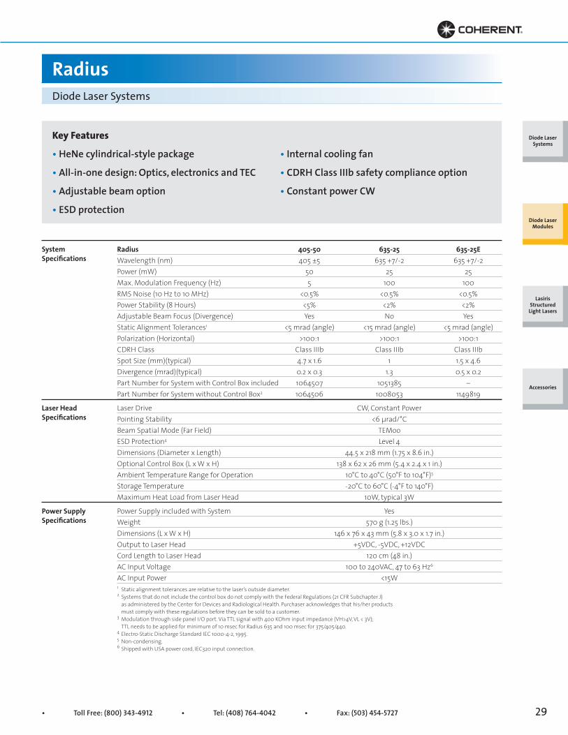
Radius 405-50 635-25 635-25EWavelength (nm) 405 ±5 635 +7/-2 635 +7/-2Power (mW) 50 25 25Max. Modulation Frequency (Hz) 5 100 100RMS Noise (10 Hz to 10 MHz) <0.5% <0.5% <0.5%Power Stability (8 Hours) <5% <2% <2%Adjustable Beam Focus (Divergence) Yes No YesStatic Alignment Tolerances1 <5 mrad (angle) <15 mrad (angle) <5 mrad (angle)Polarization (Horizontal) >100:1 >100:1 >100:1CDRH Class Class IIIb Class IIIb Class IIIbSpot Size (mm)(typical) 4.7 x 1.6 1 1.5 x 4.6Divergence (mrad)(typical) 0.2 x 0.3 1.3 0.5 x 0.2Part Number for System with Control Box included 1064507 1051385 –Part Number for System without Control Box2 1064506 1008053 1149819
Laser Drive CW, Constant PowerPointing Stability <6 μrad/°CBeam Spatial Mode (Far Field) TEMooESD Protection4 Level 4Dimensions (Diameter x Length) 44.5 x 218 mm (1.75 x 8.6 in.)Optional Control Box (L x W x H) 138 x 62 x 26 mm (5.4 x 2.4 x 1 in.)Ambient Temperature Range for Operation 10°C to 40°C (50°F to 104°F)5
Storage Temperature -20°C to 60°C (-4°F to 140°F)Maximum Heat Load from Laser Head 10W, typical 3W
Power Supply included with System YesWeight 570 g (1.25 lbs.)Dimensions (L x W x H) 146 x 76 x 43 mm (5.8 x 3.0 x 1.7 in.)Output to Laser Head +5VDC, -5VDC, +12VDCCord Length to Laser Head 120 cm (48 in.)AC Input Voltage 100 to 240VAC, 47 to 63 Hz6
AC Input Power <15W
SystemSpecifications
Laser Head Specifications
Power Supply Specifications
1 Static alignment tolerances are relative to the laser’s outside diameter.2 Systems that do not include the control box do not comply with the Federal Regulations (21 CFR Subchapter J) as administered by the Center for Devices and Radiological Health. Purchaser acknowledges that his/her products must comply with these regulations before they can be sold to a customer.3 Modulation through side panel I/O port. Via TTL signal with 400 KOhm input impedance (VH>4V, VL < 3V); TTL needs to be applied for minimum of 10 msec for Radius 635 and 100 msec for 375/405/440.4 Electro-Static Discharge Standard IEC 1000-4-2, 1995.5 Non-condensing.6 Shipped with USA power cord, IEC320 input connection.
Diode Laser Systems
Diode Laser Modules
Lasiris Structured
Light Lasers
Accessories
Superior Reliability & Performance • www.Coherent.com • [email protected]
76 mm (3.0 in.)
64 mm (2.5 in.)
Including bend radius
146 mm (5.8 in.)
~1 m cord
43 mm(1.7 in.)
be
Interlock RCA Connection
26 mm(1.0 in.)
138 mm(5.4 in.)62 mm
(2.4 in.)
~280 mm cord(11.0 in.)
RadiusDiode Laser Systems
1039966 Control Box, CDRH, Keyswitch, Interlock Control Box for Radius lasers. Included box, key, interlock RCA and cable.1080090 Cable, Extension, DB-9 M/F, 6 ft. (1.8 m) Extension cable to extend control box. Male-Female, DB-9.1040408 Plug, RCA Interlock RCA plug for Control Box, non-shorted1059300 Power Supply, LDM, 110/220VAC Radius or ULN, Desktop, 43 Watt, Triple Output
Radius Accessories
Radius Power Supply Radius Control Box
44.5 mm (1.75 in.)
218 mm (8.6 in.)
nterl ck R
cord
HeNe ComparisonRadius 635 specifications are equal to or better than most HeNe lasers in most applications. Radius lasers also cost less and come in a smaller package. Both power stability and pointing stability are superior with the Radius. Warm-up time and output power over the laser’s life are also far superior when compared to the HeNe. For all the details, please see the Radius 635 Competitive Comparison, found on the Radius page of our website, www.Coherent.com.
Radius Laser Head
Diode Laser Systems
Diode Laser Modules
Lasiris Structured
Light Lasers
Accessories

• Toll Free: (800) 343-4912 • Tel: (408) 764-4042 • Fax: (503) 454-5727 31
ULNDiode Laser Modules
ULN-Series diode laser modules are designed forapplications that require particularly low noise ormode-hop, noise-free operation. Sophisticated driveelectronics are used to ensure low noise output. Typical RMS noise is 0.06% or better for detector bandwidth from 10 Hz to 10 MHz, with practically no warm-up time.
MicroBlaze™ beam circulation technology produces ahigh-brightness, diffraction-limited circular beam thatis fully collimated with low divergence.
Overall, these low-noise, compact LabLasers are idealreplacements for HeNe lasers, which require higherpower and generate more heat.
Applications include genomics, particle counting, flowcytometry, optical storage, confocal microscopy, highthroughput drug screening, and spectroscopy. They arealso ideal for biomedical instrument design.
The ULN-Series features an alternative solution to themode-hop problem. Rather than regulate temperature,a special modulation is used to force the laser into amulti-longitudinal mode.
While a normal laser will operate in a single-modelongitudinal or oscillate between two strong modes,the modulation creates several modes of lower
intensity. As the laser temperature increases, thesemodes move like a caterpillar across the wavelengthspectrum. The movement does not allow abruptchanges, so the system operates as if there were no mode-hops.
The result is low RMS noise (~0.06%), which is stable over changes in temperature and the life of the diode laser module.
• ULN stabilizes both power and noise during temperature changes (note that wavelength varies with the standard temperature coefficient of the diode, ~0.2 nm/°C).
• ULN controls noise over the lifetime of the laser and will not develop mode-hop noise as the laser ages.
• ULN does not change the spatial qualities of the laser beam, so the beam can be focused to the same spot size, profile and shape.
The ULN laser is sold with a triple output power supplyto provide the necessary +5V and +12V to drive thelaser.
Use the LabLaser mount [part no. 0221-449-00] forconvenient heat sinking and mounting with adjustablealignment.
Diode Laser Systems
Diode Laser Modules
Lasiris Structured
Light Lasers
Accessories
Superior Reliability & Performance • www.Coherent.com • [email protected]
Key Features
• Ultra-low noise (ULN)
• RMS noise <0.06% for bandwidths of 10 Hz to 10 MHz
• Circular beam
• No mode-hop noise
• No warm-up period
• Wavelength 635 nm with 5 mW CW power
• Long lifetime
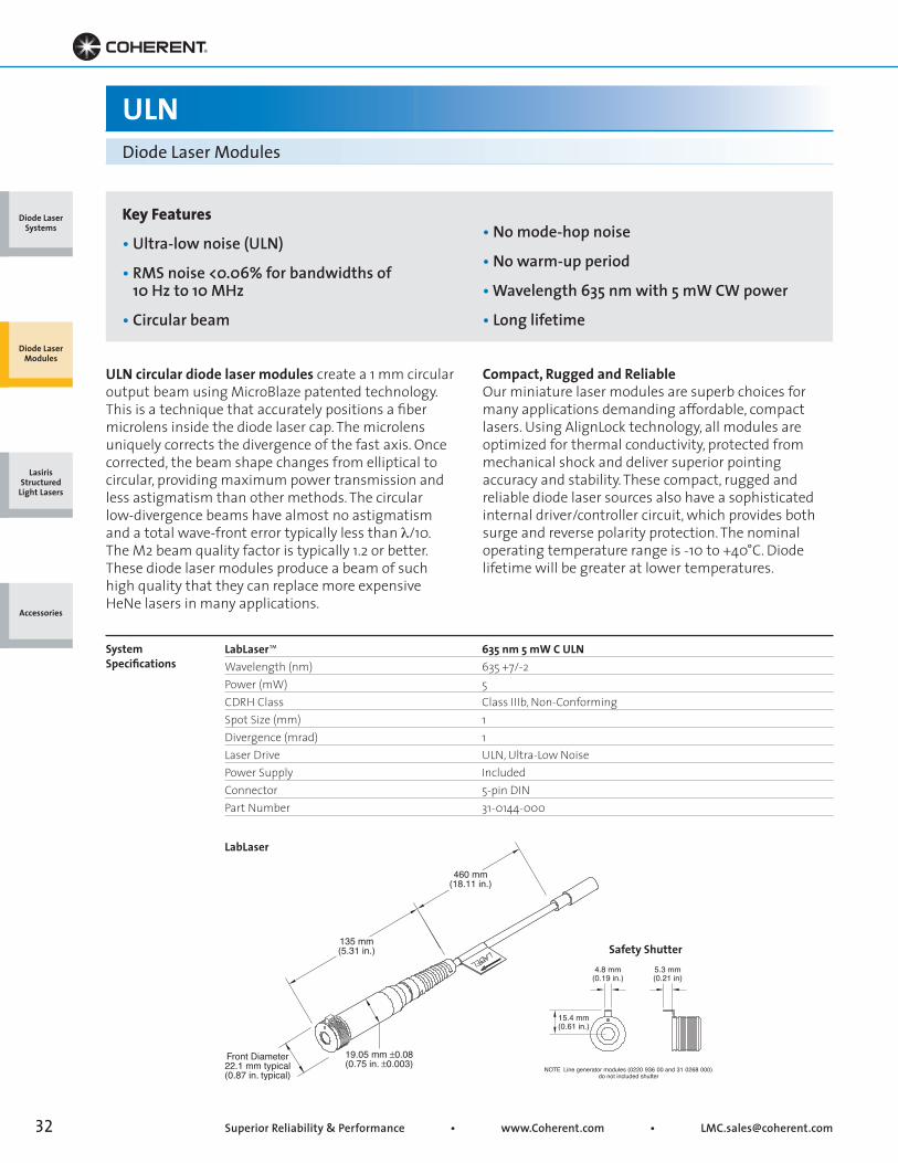
LabLaser™ 635 nm 5 mW C ULNWavelength (nm) 635 +7/-2Power (mW) 5CDRH Class Class IIIb, Non-ConformingSpot Size (mm) 1Divergence (mrad) 1Laser Drive ULN, Ultra-Low NoisePower Supply IncludedConnector 5-pin DINPart Number 31-0144-000
SystemSpecifications
ULNDiode Laser Modules
ULN circular diode laser modules create a 1 mm circularoutput beam using MicroBlaze patented technology.This is a technique that accurately positions a fibermicrolens inside the diode laser cap. The microlensuniquely corrects the divergence of the fast axis. Oncecorrected, the beam shape changes from elliptical tocircular, providing maximum power transmission andless astigmatism than other methods. The circular low-divergence beams have almost no astigmatism and a total wave-front error typically less than λ/10. The M2 beam quality factor is typically 1.2 or better. These diode laser modules produce a beam of such high quality that they can replace more expensive HeNe lasers in many applications.
Compact, Rugged and ReliableOur miniature laser modules are superb choices formany applications demanding affordable, compactlasers. Using AlignLock technology, all modules areoptimized for thermal conductivity, protected frommechanical shock and deliver superior pointingaccuracy and stability. These compact, rugged andreliable diode laser sources also have a sophisticatedinternal driver/controller circuit, which provides bothsurge and reverse polarity protection. The nominaloperating temperature range is -10 to +40°C. Diodelifetime will be greater at lower temperatures.
135 mm(5.31 in.)
460 mm(18.11 in.)
19.05 mm ±0.08(0.75 in. ±0.003)
Front Diameter22.1 mm typical(0.87 in. typical)
LabLaser
NOTE Line generator modules (0220 936 00 and 31 0268 000) do not included shutter
4.8 mm(0.19 in.)
5.3 mm(0.21 in)
15.4 mm(0.61 in.)
Safety Shutter
Diode Laser Systems
Diode Laser Modules
Lasiris Structured
Light Lasers
Accessories

• Toll Free: (800) 343-4912 • Tel: (408) 764-4042 • Fax: (503) 454-5727 33
Mounting Surface14.76 mm ±0.13 mm
(0.581 in. ±0.005)17.5 mm typical(0.69 in. typical)
Jam Nut Locking Mechanism
Body Length
Lead Length
Key Features
• Focusable VLM2-style package
• High visibility 635 nm
• Adjustable line width and focus
• Dual-element optic design
• High-quality diffractive optic
Cross-Hair Line Generators
FVLM2Cross-Hair Line Generators deliver two sharp, high-brightness, fan-angle lines at 635 nm. These adjustable focus cross-hair generators are ideal for long-lifeprojection and industrial applications. The adjustablefocus allows the width of the line to be focused, whilethe length of the line remains fixed. The line cantypically be focused as small as <0.1 mm at a distanceof 10 cm or can be focused to as small as ~0.4 mm ata distance of 1.0 meter.
The front knob allows for easy adjustment of the linewidth and focus location. During adjustment the opticsdo not rotate and focusing action is even and uniformwhile beam alignment is maintained3. A locking ring isused to secure the focus in any position. Use the VLM2mount [part no. 0221-437-00] for convenient heatsinking and mounting with adjustable alignment. Forlasers without a connector, order plug no.1057734.
FVLM2 Cross-Hair 635 nm 0.6 mW Cross-Hair 635 nm 1.7 mWWavelength (nm) 635 +7/-2 635 +7/-2Power (mW) 0.55 1.7CDRH Class Class II Class IISpot Size (mm) 1 Adjustable 1 AdjustableDivergence (mrad) 24° x 1 mrad Adjustable 24° x 1 mrad AdjustableLaser Drive1 CW CWPower Supply2 5 to 10VDC 5 to 10VDCBody Length (mm) 48 to 55 48 to 55Lead Length (mm) 610 610Connector None NonePart Number 0222-210-00 0222-209-001 Laser Drive is Continuous Wave (CW) with constant power. 2 Power Supply: For modules with 5-10VDC it is recommended that the module be operated at 5V. 3 Note the focus adjustment may slightly affect the beam-pointing direction. Due to the numerical aperture of the lens, slight variations in beam output power may occur as the lens is adjusted.
SystemSpecifications
Diode Laser Systems
Diode Laser Modules
Lasiris Structured
Light Lasers
Accessories

Superior Reliability & Performance • www.Coherent.com • [email protected]
Focusable Line Generator Modules
Focusable diode laser modules combine the technol-ogy of high-quality diode lasers with superior optics,sophisticated electronics and rugged alignmentpackaging. These modules can also be used in manyapplications to reduce the requirements for externaloptics. The result is an overall system that is smaller,simpler and less costly.
The adjustable focus is a great benefit for manyapplications. For machine vision, particle measure-ments and inspection—and their inherent need for direct measurements—the beam can be focused at a distance for the smallest spot size to optimize the system resolution.
The front knob allows for easy adjustment. Duringadjustment the optics do not rotate and focusingaction is even and uniform while beam alignment is maintained1. A locking ring is used to secure the focus in any position. Use the VLM2 mount [part no. 0221-437-00] for convenient heat sinking and mount-
ing with adjustable alignment. For lasers without a connector, order plug no. 1057734.
Compact, Rugged and ReliableOur miniature laser modules are superb choices formany applications demanding affordable, compactlasers. Using AlignLock technology, all modules areoptimized for thermal conductivity, protected frommechanical shock and deliver superior pointingaccuracy and stability. These compact, rugged andreliable diode laser sources also have a sophisticatedinternal driver/controller circuit, which provides bothsurge and reverse polarity protection. The nominaloperating temperature range is -10 to +40°C. Diodelifetime will be greater at lower temperatures.
Focusable line generators deliver sharp lines with adjustable line width, while the length of the line remains fixed. The line can be typically focused as small as <0.1 mm at a distance of 10 cm or can be focused to as small as ~0.4 mm at a distance of 1 meter.
1 The focus adjustment may slightly affect the beam-pointing direction. Due to the numerical aperture of the lens, slight variations in beam output power may occur as the lens is adjusted.
Diode Laser Systems
Diode Laser Modules
Lasiris Structured
Light Lasers
Accessories

• Toll Free: (800) 343-4912 • Tel: (408) 764-4042 • Fax: (503) 454-5727 35
Focusable Line Generator Modules
Key Features
• Focusable VLM2 style package
• High visibility 635 nm
• Adjustable divergence and focus
FVLM2 635 nm 1.8 mW 60°Wavelength (nm) 635 +7/-2Power (mW) 1.8CDRH Class Class IISpot Size (mm) 1 AdjustableDivergence (mrad) 60° x 1 mrad AdjustableLaser Drive CWPower Supply1 5 to 10VDCBody Length (mm) 48 to 54Lead Length (mm) 610Connector nonePart Number 0220-846-00
SystemSpecifications
1 Power Supply: For modules with 5-10VDC it is recommended that the module be operated at 5V.
Advantages of the Focus FeatureThe focus feature can be used to:
• Adjust the beam propagation so that it diverges to create a larger spot at the target for broader illumination.
• Adjust the beam so that it converges to create a specific focus spot size at a certain working distance.
• Adjust the beam so that the beam waist is at a particular point in space.
• Adjust the beam to move the focus spot location when an external objective lens is used. This is especially useful when matching multiple wave- lengths into the same beam focus position.
• Adjust the beam at the laser to reduce the need for expensive and bulky adjustable beam expanders.
Mounting Surface14.76 mm ±0.13 mm
(0.581 in. ±0.005)17.5 mm typical(0.69 in. typical)
Jam Nut Locking Mechanism
Body Length
Lead Length
FVLM2
Diode Laser Systems
Diode Laser Modules
Lasiris Structured
Light Lasers
Accessories
Superior Reliability & Performance • www.Coherent.com • [email protected]
Line Generator Diode Laser Modules
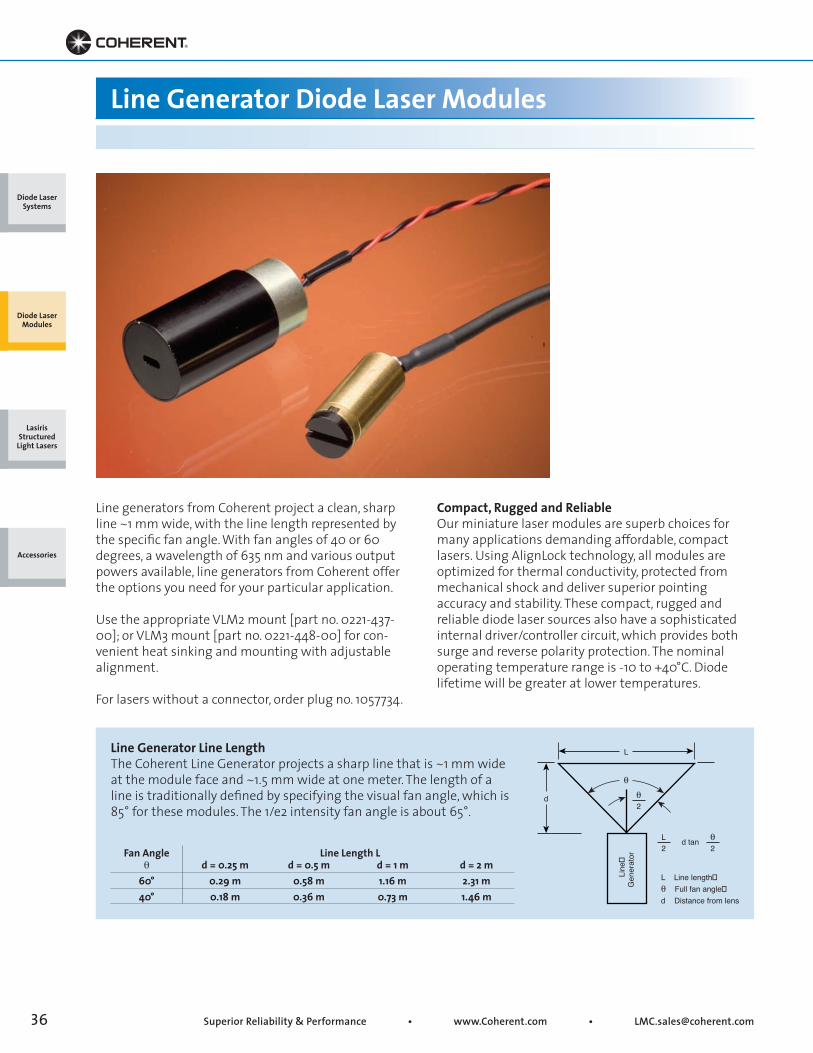
Line generators from Coherent project a clean, sharpline ~1 mm wide, with the line length represented bythe specific fan angle. With fan angles of 40 or 60 degrees, a wavelength of 635 nm and various output powers available, line generators from Coherent offer the options you need for your particular application.
Use the appropriate VLM2 mount [part no. 0221-437-00]; or VLM3 mount [part no. 0221-448-00] for con-venient heat sinking and mounting with adjustable alignment.
For lasers without a connector, order plug no. 1057734.
Compact, Rugged and ReliableOur miniature laser modules are superb choices formany applications demanding affordable, compactlasers. Using AlignLock technology, all modules areoptimized for thermal conductivity, protected frommechanical shock and deliver superior pointingaccuracy and stability. These compact, rugged andreliable diode laser sources also have a sophisticatedinternal driver/controller circuit, which provides bothsurge and reverse polarity protection. The nominaloperating temperature range is -10 to +40°C. Diodelifetime will be greater at lower temperatures.
Line Generator Line LengthThe Coherent Line Generator projects a sharp line that is ~1 mm wide at the module face and ~1.5 mm wide at one meter. The length of a line is traditionally defined by specifying the visual fan angle, which is 85° for these modules. The 1/e2 intensity fan angle is about 65°.
L
L
L Line length�θ Full fan angle�d Distance from lens
d tan2
θ2
Line
�G
ener
ator
d θ2
θ
Fan Angle Line Length L θ d = 0.25 m d = 0.5 m d = 1 m d = 2 m 60° 0.29 m 0.58 m 1.16 m 2.31 m 40° 0.18 m 0.36 m 0.73 m 1.46 m
Diode Laser Systems
Diode Laser Modules
Lasiris Structured
Light Lasers
Accessories

• Toll Free: (800) 343-4912 • Tel: (408) 764-4042 • Fax: (503) 454-5727 37
Key Features
• VLM2 and VLM3-style packages
• Optional adjustable line width and focus
• 40° or 60° fan angles
• High brightness 635 nm
Line Generator Diode Laser Modules
FVLM2 LG3 635 nm 1.5 mW 40° LG2 635 nm 2 mW 60°Wavelength (nm) 635 +7/-2 635 +7/-2Power (mW) 1.5 2CDRH Class Class II Class IISpot Size (mm) 1 1Divergence (mrad) 40° x 1 60° x 1Laser Drive1 CW CWPower Supply2 3 to 6VDC 5 to 10VDCBody Length (mm) 24 35Lead Length (mm) 914 914Connector none nonePart Number 0222-037-00 0220-934-00
SystemSpecifications
1 Laser Drive is Continuous Wave (CW) with constant power. For MVP option the laser includes a 3rd wire for Modulation and Variable Power Control2 Power Supply: For modules with 5-10VDC it is recommended that the module be operated at 5V. For modules with 3-6VDC it is recommended that the module be operated at 3.3V or 5V.
Body Length
Lead Length
Mounting Surface14.76 mm ±0.13(0.581 in. ±0.005)
16.89 mm ±0.08(0.665 in. ±0.003)
25.4 mm typical(1.0 in. typical)
Body Length
Lead Length
9.55 mm ±0.13(0.375 in. ±0.005)
LG2 LG3
Diode Laser Systems
Diode Laser Modules
Lasiris Structured
Light Lasers
Accessories
Superior Reliability & Performance • www.Coherent.com • [email protected]
Miniature Diode Laser Modules
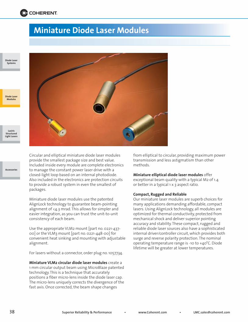
Circular and elliptical miniature diode laser modulesprovide the smallest package size and best value.Included inside every module are complete electronicsto manage the constant power laser drive with aclosed-light loop based on an internal photodiode.Also included in the electronics are protection circuitsto provide a robust system in even the smallest ofpackages.
Miniature diode laser modules use the patentedAlignLock technology to guarantee beam-pointingalignment of <4.3 mrad. This allows for simpler andeasier integration, as you can trust the unit-to-unitconsistency of each beam.
Use the appropriate VLM2 mount [part no. 0221-437-00] or the VLM3 mount [part no. 0221-448-00] forconvenient heat sinking and mounting with adjustablealignment.
For lasers without a connector, order plug no. 1057734.
Miniature VLM2 circular diode laser modules create a1 mm circular output beam using MicroBlaze patentedtechnology. This is a technique that accuratelypositions a fiber micro-lens inside the diode laser cap.The micro-lens uniquely corrects the divergence of thefast axis. Once corrected, the beam shape changes
from elliptical to circular, providing maximum powertransmission and less astigmatism than othermethods.
Miniature elliptical diode laser modules offerexceptional beam quality with a typical M2 of 1.4or better in a typical 1 x 3 aspect ratio.
Compact, Rugged and ReliableOur miniature laser modules are superb choices formany applications demanding affordable, compactlasers. Using AlignLock technology, all modules areoptimized for thermal conductivity, protected frommechanical shock and deliver superior pointingaccuracy and stability. These compact, rugged andreliable diode laser sources also have a sophisticatedinternal driver/controller circuit, which provides bothsurge and reverse polarity protection. The nominaloperating temperature range is -10 to +40°C. Diodelifetime will be greater at lower temperatures.
Diode Laser Systems
Diode Laser Modules
Lasiris Structured
Light Lasers
Accessories
• Toll Free: (800) 343-4912 • Tel: (408) 764-4042 • Fax: (503) 454-5727 39
Body Length
Lead Length
14.76 mm ±0.13(0.581 in. ±0.005)
Body Length
Lead Length
9.55 mm ±0.13(0.375 in. ±0.005)
Key Features
• VLM2 and VLM3-style packages
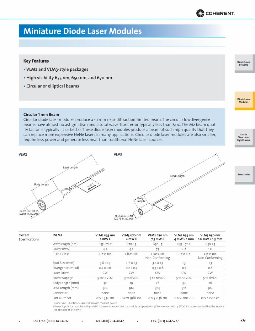
• High visibility 635 nm, 650 nm, and 670 nm
• Circular or elliptical beams
Miniature Diode Laser Modules
FVLM2 VLM2 635 nm VLM3 670 nm VLM2 670 nm VLM2 635 nm VLM3 650 nm 4 mW E 4 mW E 7.5 mW E 4 mW C 1 mm 1.6 mW C 1.3 mmWavelength (nm) 635 +7/-2 670 ±5 670 ±5 635 +7/-2 650 ±5Power (mW) 4.2 4.2 7.5 4.2 1.6CDRH Class Class IIIa Class IIIa Class IIIb Class IIIa Class IIIa Non-Conforming Non-ConformingSpot Size (mm) 5.8 x 1.7 4.6 x 1.3 3.4 x 1.3 1.3 1.3Divergence (mrad) 0.2 x 0.6 0.2 x 0.7 0.3 x 0.8 0.7 0.8Laser Drive1 CW CW CW CW CWPower Supply2 5 to 10VDC 3 to 6VDC 5 to 10VDC 5 to 10VDC 5 to 6VDCBody Length (mm) 32 19 28 34 26Lead Length (mm) 914 914 305 914 914Connector none none none none nonePart Number 0221-534-00 0220-968-00 0223-038-00 0222-200-00 0222-002-01
SystemSpecifications
1 Laser Drive is Continuous Wave (CW) with constant power. 2 Power Supply: For modules with 5-10VDC it is recommended that the module be operated at 5V. For modules with 3-6VDC it is recommended that the module be operated at 3.3V or 5V.
VLM2 VLM3
Circular 1 mm BeamCircular diode laser modules produce a ~1 mm near-diffraction-limited beam. The circular lowdivergence beams have almost no astigmatism and a total wave-front error typically less than λ/10. The M2 beam qual-ity factor is typically 1.2 or better. These diode laser modules produce a beam of such high quality that they can replace more expensive HeNe lasers in many applications. Circular diode laser modules are also smaller, require less power and generate less heat than traditional HeNe laser sources.
Diode Laser Systems
Diode Laser Modules
Lasiris Structured
Light Lasers
Accessories
Superior Reliability & Performance • www.Coherent.com • [email protected]
What is Structured Light?Structured light is the projection of a light pattern (plane, grid, or more complex shape) at a known angle onto an object. This technique can be very useful for imaging and acquiring dimensional information. The most often used light pattern is generated by fanning out a light beam into a sheet-of-light. When a sheet-of-light intersects with an object, a bright line of light can be seen on the surface of the object. By viewing this line of light from an angle, the observed distortions in the line can be translated into height variations.
LasirisApplication Primers
Acquiring 2-dimensional information Scanning the object with the light constructs 3-D information about the shape of the object. This is the basic principle behind depth perception for machines, or 3D machine vision. In this case, structured lighting is sometimes described as active triangulation.
Since structured lighting can be used to determine the shape of an object in machine vision applications, it can also help recognize and locate an object in an environment. These features make structured lighting useful in assembly lines implementing process control or quality control. These methods use structured lighting for alignment and inspection purposes. Structured light systems can
drastically transform a manufacturing plant by decreasing process variation, reducing production time, allowing automation of assembly lines, increasing precision, and generally decreasing overall cost. Although other types of light can be used for structured lighting, laser light is the best choice when precision and reliability are important.
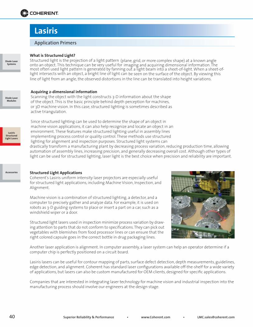
Structured Light ApplicationsCoherent’s Lasiris uniform intensity laser projectors are especially useful for structured light applications, including Machine Vision, Inspection, and Alignment.
Machine vision is a combination of structured lighting, a detector, and a computer to precisely gather and analyze data. For example, it is used on robots as 3-D guiding systems to place or insert a part on a car, such as a windshield wiper or a door.
Structured light lasers used in inspection minimize process variation by draw-
ing attention to parts that do not conform to specifications. They can pick out vegetables with blemishes from food processor lines or can ensure that the right colored capsule goes in the correct bottle in drug packaging lines.
Another laser application is alignment. In computer assembly, a laser system can help an operator determine if a computer chip is perfectly positioned on a circuit board.
Lasiris lasers can be useful for contour mapping of parts, surface defect detection, depth measurements, guidelines, edge detection, and alignment. Coherent has standard laser configurations available off-the-shelf for a wide variety of applications, but lasers can also be custom manufactured for OEM clients, designed for specific applications.
Companies that are interested in integrating laser technology for machine vision and industrial inspection into the manufacturing process should involve our engineers at the design stage.
Diode Laser Systems
Diode Laser Modules
Lasiris Structured
Light Lasers
Accessories
• Toll Free: (800) 343-4912 • Tel: (408) 764-4042 • Fax: (503) 454-5727 41
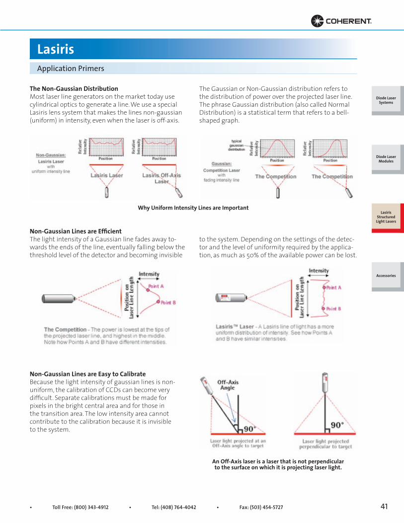
The Non-Gaussian DistributionMost laser line generators on the market today use cylindrical optics to generate a line. We use a special Lasiris lens system that makes the lines non-gaussian (uniform) in intensity, even when the laser is off-axis.
Non-Gaussian Lines are EfficientThe light intensity of a Gaussian line fades away to-wards the ends of the line, eventually falling below the threshold level of the detector and becoming invisible
Non-Gaussian Lines are Easy to CalibrateBecause the light intensity of gaussian lines is non- uniform, the calibration of CCDs can become very difficult. Separate calibrations must be made for pixels in the bright central area and for those in the transition area. The low intensity area cannot contribute to the calibration because it is invisible to the system.
LasirisApplication Primers
The Gaussian or Non-Gaussian distribution refers to the distribution of power over the projected laser line. The phrase Gaussian distribution (also called Normal Distribution) is a statistical term that refers to a bell-shaped graph.
to the system. Depending on the settings of the detec-tor and the level of uniformity required by the applica-tion, as much as 50% of the available power can be lost.
Why Uniform Intensity Lines are Important
An Off-Axis laser is a laser that is not perpendicular to the surface on which it is projecting laser light.
Diode Laser Systems
Diode Laser Modules
Lasiris Structured
Light Lasers
Accessories
Superior Reliability & Performance • www.Coherent.com • [email protected]
Lasiris Lasers can easily be adapted to an Off-Axis angle while maintaining uniform line intensity simply slide the line generating optic head slightly off center, see
LasirisApplication Primers
figure below, turn the laser ON and move optical head up and down until the projected line is uniform, then tighten the set-screw.
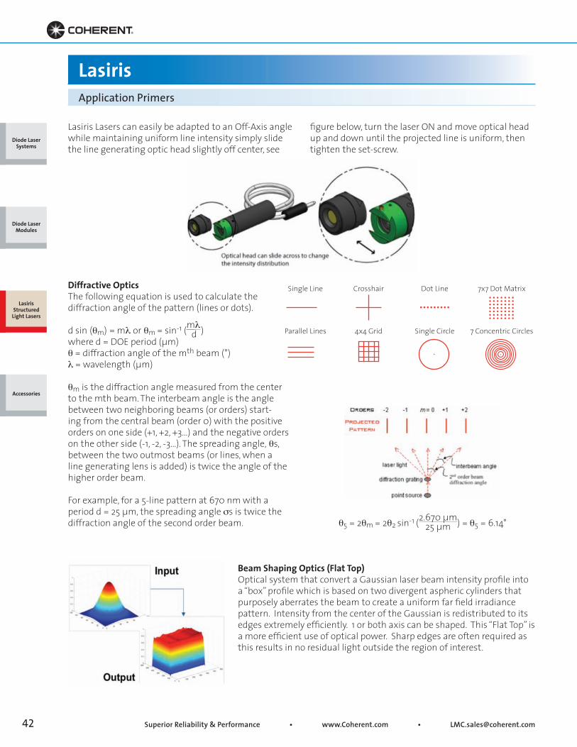
Diffractive OpticsThe following equation is used to calculate the diffraction angle of the pattern (lines or dots).
d sin (θm) = mλ or θm = sin-1 (mλd )
where d = DOE period (μm)θ = diffraction angle of the mth beam (°)λ = wavelength (μm)
θm is the diffraction angle measured from the center to the mth beam. The interbeam angle is the angle between two neighboring beams (or orders) start-ing from the central beam (order 0) with the positive orders on one side (+1, +2, +3...) and the negative orders on the other side (-1, -2, -3...). The spreading angle, θs, between the two outmost beams (or lines, when a line generating lens is added) is twice the angle of the higher order beam.
For example, for a 5-line pattern at 670 nm with a period d = 25 μm, the spreading angle ss is twice the diffraction angle of the second order beam.
Beam Shaping Optics (Flat Top)Optical system that convert a Gaussian laser beam intensity profile into a “box” profile which is based on two divergent aspheric cylinders that purposely aberrates the beam to create a uniform far field irradiance pattern. Intensity from the center of the Gaussian is redistributed to its edges extremely efficiently. 1 or both axis can be shaped. This “Flat Top” is a more efficient use of optical power. Sharp edges are often required as this results in no residual light outside the region of interest.
Single Line Crosshair Dot Line 7x7 Dot Matrix
Parallel Lines 4x4 Grid Single Circle 7 Concentric Circles
θ5 = 2θm = 2θ2 sin-1 (2.670 μm) = θ5 = 6.14°25 μm
Diode Laser Systems
Diode Laser Modules
Lasiris Structured
Light Lasers
Accessories
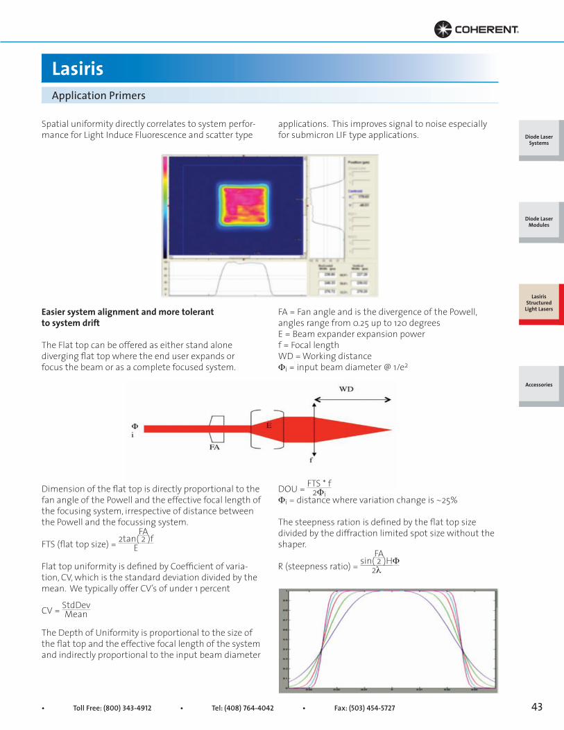
• Toll Free: (800) 343-4912 • Tel: (408) 764-4042 • Fax: (503) 454-5727 43
LasirisApplication Primers
Spatial uniformity directly correlates to system perfor-mance for Light Induce Fluorescence and scatter type
applications. This improves signal to noise especially for submicron LIF type applications.
Easier system alignment and more tolerant to system drift
The Flat top can be offered as either stand alone diverging flat top where the end user expands or focus the beam or as a complete focused system.
FA = Fan angle and is the divergence of the Powell, angles range from 0.25 up to 120 degreesE = Beam expander expansion powerf = Focal lengthWD = Working distanceΦi = input beam diameter @ 1/e2
Dimension of the flat top is directly proportional to the fan angle of the Powell and the effective focal length of the focusing system, irrespective of distance between the Powell and the focussing system.
FTS (flat top size) = 2tan( 2 )f
Flat top uniformity is defined by Coefficient of varia-tion, CV, which is the standard deviation divided by the mean. We typically offer CV’s of under 1 percent
CV = StdDev
The Depth of Uniformity is proportional to the size of the flat top and the effective focal length of the system and indirectly proportional to the input beam diameter
DOU = FTS * f Φi = distance where variation change is ~25%
The steepness ration is defined by the flat top size divided by the diffraction limited spot size without the shaper.
R (steepness ratio) = sin( 2 )HΦE
Mean
FA
2Φi
2λ
FA
Diode Laser Systems
Diode Laser Modules
Lasiris Structured
Light Lasers
Accessories

Superior Reliability & Performance • www.Coherent.com • [email protected]
Lasiris SNFStructured Light Pattern Generating Laser
Top View
Top View
Standard SNFLaser
SNF Laser with SeparateElectronics Option
See notes:(e, f, g)Optical head
2.730 ±0.015[69.34 ±0.38]
2.000 [50.80]
ø0.734 [ø18.64]
Clamping surface
ø0.750 +0 [ø19.05 +0 ] -0.002 -0.05(Clamping surface) PSC
LED
SwitchBNC (optional)Cable lengths standard
and custom availableNotes: (e) Add 0.500 [12.70] for the 501L series of pattern generators (f) Add 0.750 [19.05] for the 701L series of pattern generators (g) Add 1.200 [30.48] for the 701L series with a type 2 collimating lens
1.110 ±0.025 [28.19 ±0.64]
0.685 ±0.015[17.40 ±0.38]
ø0.734[ø18.64]
See Notes: (e, f, g)Optical head
Clamping surface
ø0.750 +0 -0.002[ø19.05 +0 ] -0.05(Clamping surface)
ø0.750 +0 -0.002[ø19.05 +0 ] -0.05
1.62 ±0.02[41.15 ±0.50]
Cable lengths standard and custom available
LEDSwitch
PSC
BNC (optional)
Diode Laser Systems
Diode Laser Modules
Lasiris Structured
Light Lasers
Accessories
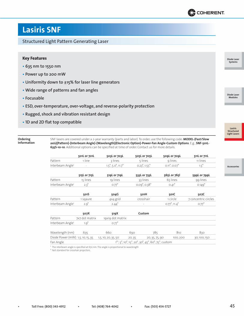
• Toll Free: (800) 343-4912 • Tel: (408) 764-4042 • Fax: (503) 454-5727 45
SNF lasers are covered under a 2-year warranty (parts and labor). To order, use the following code: MODEL-(Fast/Slow axis)(Pattern)-(Interbeam Angle)-(Wavelength)(Electronic Option)-Power-Fan Angle-Custom Options. E.g., SNF-501L-635S-10-10. Additional options can be specified at time of order. Contact us for more details.
501L or 701L 503L or 703L 505L or 705L 509L or 709L 511L or 711LPattern 1 line 3 lines 5 lines 9 lines 11 linesInterbeam Angle1 - 1.5°, 5.0°, 11.7° 0.23°, 1.55° 0.11°, 0.07° 1.5°
515L or 715L 519L or 719L 533L or 733L 565L or 765l 599L or 799LPattern 15 lines 19 lines 33 lines 65 lines 99 linesInterbeam Angle1 2.3° 0.77° 0.09°, 0.38° 0.41° 0.149°
501S 504G 501H 501C 507CPattern 1 sqaure 4x4 grid crosshair 1 circle 7 concentric circlesInterbeam Angle1 2.9° 2.44° - 0.77°, 11.4° 0.77°
507X 519X CustomPattern 7x7 dot matrix 19x19 dot matrixInterbeam Angle1 1.9° 0.77°
Wavelength (nm) 635 660 690 785 810 830Diode Power (mW) 1,5, 10, 15, 35 1,5, 10, 20, 35, 50 20, 35 20, 35, 75, 90 100, 200 30, 100, 150Fan Angle 1°2, 5°, 10°, 15°, 20°, 30°, 45°, 60°, 75°, custom
Lasiris SNFStructured Light Pattern Generating Laser
Key Features
• 635 nm to 1550 nm
• Power up to 200 mW
• Uniformity down to ±15% for laser line generators
• Wide range of patterns and fan angles
• Focusable
• ESD, over-temperature, over-voltage, and reverse-polarity protection
• Rugged, shock and vibration resistant design
• 1D and 2D flat top compatible
1 The interbeam angle is specified at 670 nm. The angle is proportional to wavelength2 Not standard for crosshair projectors.
Ordering Information
Diode Laser Systems
Diode Laser Modules
Lasiris Structured
Light Lasers
Accessories

Superior Reliability & Performance • www.Coherent.com • [email protected]
Lasiris SNFStructured Light Pattern Generating Laser
Uniform Intensity
Focusing Performance
Conventional laser line patterns are often generated by cylindrical optics that produce a Gaussian line profile with abright center and fading ends. Lasiris patented beam shaping optics spread the light into an evenly illuminated line.The result is a crisp, uniform line with sharp ends.
Line Intensity Profile Along Line Length
The following figures show the typical focusing and depth-of-field performance of the SNF laser line generator. Thefocus charts indicate the minimum line thickness (at 1/e2) achievable for a specific projection distance. The depth-of-field is defined as twice the distance over which the thickness of the line has increased by a factor of √2.
Focusing and Depth-of-Field Performance
1 Typical profile.
1.0
0.8
0.6
0.4
0.2
0-10 -8 -6 -4 -2 0 2 4 6 8 10
Rela
tive
Inte
nsity
Relative Angular Position
1.0
0.8
0.6
0.4
0.2
0-10 -8 -6 -4 -2 0 2 4 6 8 10
Rela
tive
Inte
nsity
Relative Angular Position
125
100
175
150
200
75
50
25
00 5 10 15 20 25M
inim
um L
ine
Thic
knes
s (µ
m)
Projection Distance (cm)
2 500
2 000
3 500
3 000
4 000
1 500
1 000
500
00 50 100 150 200 250 300 350 400M
inim
um L
ine
Thic
knes
s (µ
m)
Projection Distance (cm)
0
20
40
60
80
100
0 5 10 15 20 25
Dept
h of
Fie
ld (m
m)
Dept
h of
Fie
ld (m
)
Projection Distance (cm)
20
0
4
8
12
16
0 50 100 150 200 250 300 350 400
Projection Distance (cm)
Focusing
Long Range
Depth-of-field
Long Range
Lasiris Non-Gaussian Line1
Relative Intensity vs. Angular Position Along Line Length
Gaussian Line from Cylindrical Lens
FastSlow
Diode Laser Systems
Diode Laser Modules
Lasiris Structured
Light Lasers
Accessories
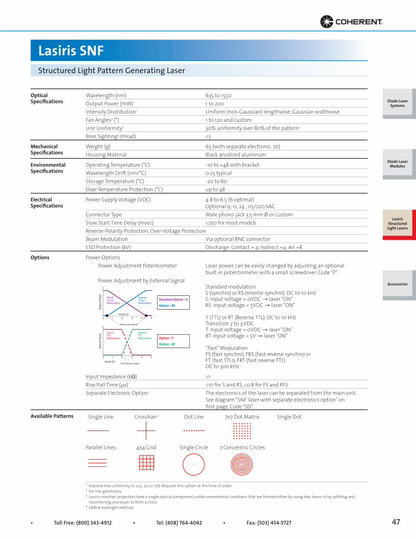
• Toll Free: (800) 343-4912 • Tel: (408) 764-4042 • Fax: (503) 454-5727 47
Lasiris SNFStructured Light Pattern Generating Laser
OpticalSpecifications
MechanicalSpecifications
EnvironmentalSpecifications
ElectricalSpecifications
Options
Available Patterns
Wavelength (nm) 635 to 1550Output Power (mW) 1 to 200Intensity Distribution1 Uniform (non-Gaussian) lengthwise, Gaussian widthwiseFan Angles2 (°) 1 to 120 and customLine Uniformity2 30% uniformity over 80% of the pattern1
Bore Sighting4 (mrad) <3
Weight (g) 65 (with separate electronic: 70)Housing Material Black anodized aluminum
Operating Temperature (°C) -10 to +48 with bracketWavelength Drift (nm/°C) 0.25 typicalStorage Temperature (°C) -20 to 60Over-Temperature Protection (°C) up to 48
Power Supply Voltage (VDC) 4.8 to 6.5 (6 optimal) Optional 9, 12, 24 , 115/220 VACConnector Type Male phono-jack 3.5 mm Ø or customSlow Start Time Delay (msec) <250 for most modelsReverse-Polarity Protection, Over-Voltage ProtectionBeam Modulation Via optional BNC connectorESD Protection (kV) Discharge: Contact = 4; Indirect =4; Air =8
Power Options Power Adjustment Potentiometer Laser power can be easily changed by adjusting an optional built-in potentiometer with a small screwdriver. Code “P”. Power Adjustment by External Signal Standard modulation S (synchro) or RS (reverse synchro): DC to 10 kHz S: Input voltage = 0VDC → laser “ON” RS: Input voltage = 5VDC → laser “ON”
T (TTL) or RT (Reverse TTL): DC to 10 kHz Transition 2 to 3 VDC T: Input voltage = 0VDC → laser “ON” RT: Input voltage = 5V → laser “ON”
“Fast” Modulation FS (fast synchro), FRS (fast reverse synchro) or FT (fast TTL0, FRT (fast reverse TTL) DC to 300 kHz
Input Impedance (kW) >1Rise/Fall Time (μs) <10 for S and RS, <0.8 for FS and RFSSeparate Electronic Option The electronics of the laser can be separated from the main unit. See diagram “SNF laser with separate electronics option” on first page. Code “SD”.
Single Line Crosshair3 Dot Line 7x7 Dot Matrix Single Dot
Parallel Lines 4x4 Grid Single Circle 7 Concentric Circles
1 Improve line uniformity to ±25, 20, or 15%. Request this option at the time of order.2 For line generators.3 Lasiris crosshair projectors have a single optical component, unlike conventional crosshairs that are formed either by using two lasers or by splitting and recombining one beam to form a cross.4 Define boresight method.
ReverseTTLModulation
Vmod (V)0 1 2 3 4 5
DirectTTLModulation
Optic
al Po
wer
Transitional states
ReverseLinearModulation
Vmod (V)0 1 2 3 4 5
DirectLinearModulation
Outp
ut Po
wer
Factory set values
Standard Option –S
Option –RS
Option –T
Option –RT
Diode Laser Systems
Diode Laser Modules
Lasiris Structured
Light Lasers
Accessories
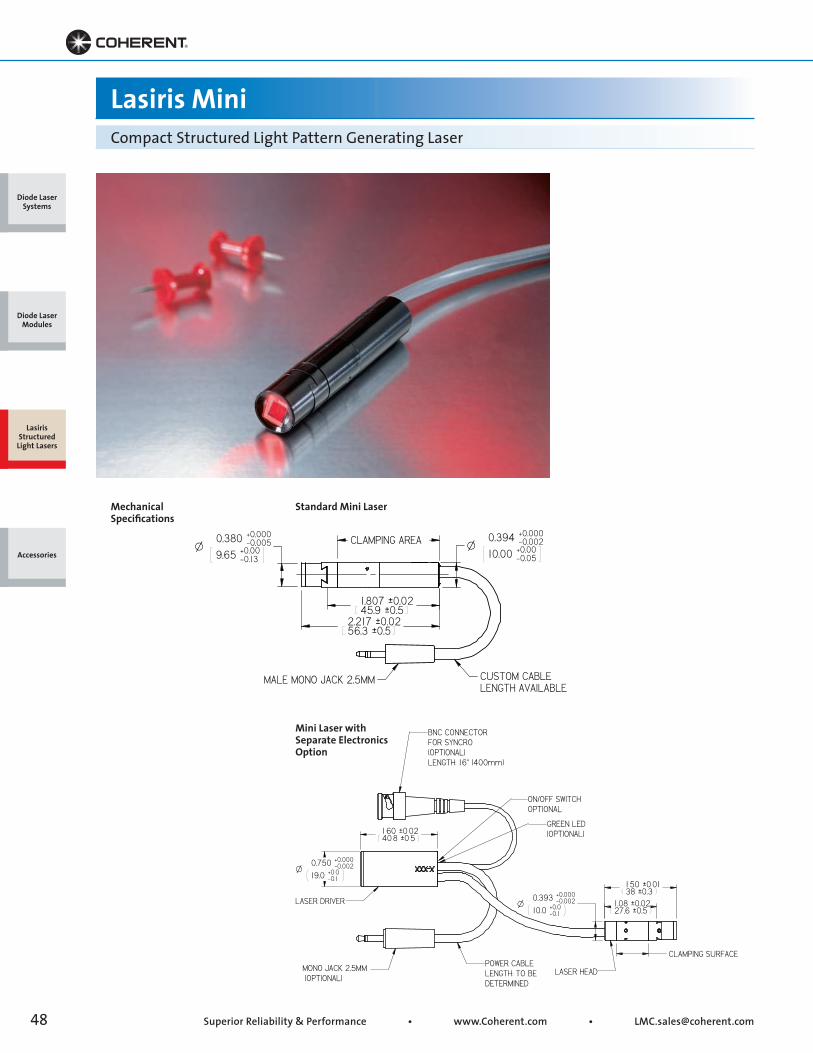
Superior Reliability & Performance • www.Coherent.com • [email protected]
NLESS O HER IS S EC FIED :
Lasiris MiniCompact Structured Light Pattern Generating Laser
Mechanical Specifications
Standard Mini Laser
Mini Laser with Separate Electronics Option
Diode Laser Systems
Diode Laser Modules
Lasiris Structured
Light Lasers
Accessories
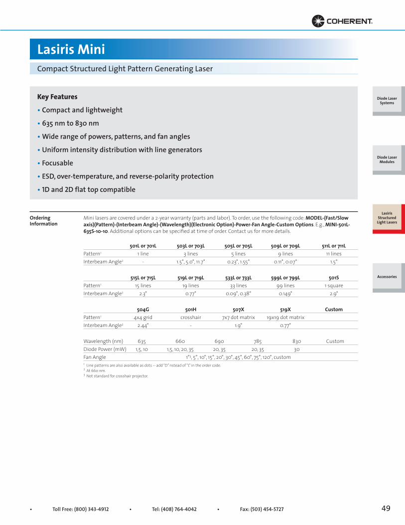
• Toll Free: (800) 343-4912 • Tel: (408) 764-4042 • Fax: (503) 454-5727 49
Lasiris MiniCompact Structured Light Pattern Generating Laser
Key Features
• Compact and lightweight
• 635 nm to 830 nm
• Wide range of powers, patterns, and fan angles
• Uniform intensity distribution with line generators
• Focusable
• ESD, over-temperature, and reverse-polarity protection
• 1D and 2D flat top compatible
Ordering Information
Mini lasers are covered under a 2-year warranty (parts and labor). To order, use the following code: MODEL-(Fast/Slow axis)(Pattern)-(Interbeam Angle)-(Wavelength)(Electronic Option)-Power-Fan Angle-Custom Options. E.g., MINI-501L-635S-10-10. Additional options can be specified at time of order. Contact us for more details.
501L or 701L 503L or 703L 505L or 705L 509L or 709L 511L or 711LPattern1 1 line 3 lines 5 lines 9 lines 11 linesInterbeam Angle2 - 1.5°, 5.0°, 11.7° 0.23°, 1.55° 0.11°, 0.07° 1.5°
515L or 715L 519L or 719L 533L or 733L 599L or 799L 501SPattern1 15 lines 19 lines 33 lines 99 lines 1 squareInterbeam Angle2 2.3° 0.77° 0.09°, 0.38° 0.149° 2.9°
504G 501H 507X 519X CustomPattern1 4x4 grid crosshair 7x7 dot matrix 19x19 dot matrixInterbeam Angle2 2.44° - 1.9° 0.77°
Wavelength (nm) 635 660 690 785 830 CustomDiode Power (mW) 1,5, 10 1,5, 10, 20, 35 20, 35 20, 35 30 Fan Angle 1°3, 5°, 10°, 15°, 20°, 30°, 45°, 60°, 75°, 120°, custom1 Line patterns are also available as dots -- add “D” nstead of “L” in the order code.2 At 660 nm.3 Not standard for crosshair projector.
Diode Laser Systems
Diode Laser Modules
Lasiris Structured
Light Lasers
Accessories
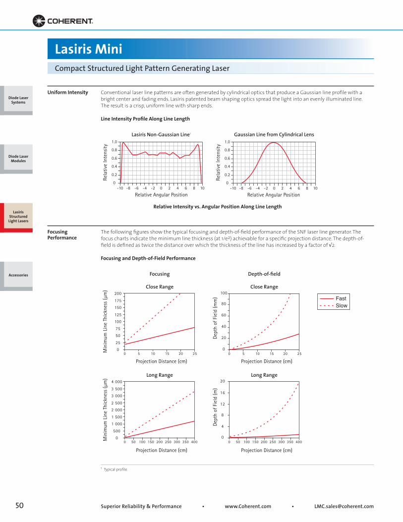
Superior Reliability & Performance • www.Coherent.com • [email protected]
Lasiris MiniCompact Structured Light Pattern Generating Laser
Uniform Intensity
Focusing Performance
Conventional laser line patterns are often generated by cylindrical optics that produce a Gaussian line profile with abright center and fading ends. Lasiris patented beam shaping optics spread the light into an evenly illuminated line.The result is a crisp, uniform line with sharp ends.
Line Intensity Profile Along Line Length
The following figures show the typical focusing and depth-of-field performance of the SNF laser line generator. Thefocus charts indicate the minimum line thickness (at 1/e2) achievable for a specific projection distance. The depth-of-field is defined as twice the distance over which the thickness of the line has increased by a factor of √2.
Focusing and Depth-of-Field Performance
1 Typical profile.
1.0
0.8
0.6
0.4
0.2
0-10 -8 -6 -4 -2 0 2 4 6 8 10
Rela
tive
Inte
nsity
Relative Angular Position
1.0
0.8
0.6
0.4
0.2
0-10 -8 -6 -4 -2 0 2 4 6 8 10
Rela
tive
Inte
nsity
Relative Angular Position
125
100
175
150
200
75
50
25
00 5 10 15 20 25M
inim
um L
ine
Thic
knes
s (µ
m)
Projection Distance (cm)
2 500
2 000
3 500
3 000
4 000
1 500
1 000
500
00 50 100 150 200 250 300 350 400M
inim
um L
ine
Thic
knes
s (µ
m)
Projection Distance (cm)
0
20
40
60
80
100
0 5 10 15 20 25
Dept
h of
Fie
ld (m
m)
Dept
h of
Fie
ld (m
)
Projection Distance (cm)
20
0
4
8
12
16
0 50 100 150 200 250 300 350 400
Projection Distance (cm)
Close Range
Long Range
Close Range
Long Range
Lasiris Non-Gaussian Line1
Relative Intensity vs. Angular Position Along Line Length
Gaussian Line from Cylindrical Lens
FastSlow
Focusing Depth-of-field
Diode Laser Systems
Diode Laser Modules
Lasiris Structured
Light Lasers
Accessories

• Toll Free: (800) 343-4912 • Tel: (408) 764-4042 • Fax: (503) 454-5727 51
Lasiris MiniCompact Structured Light Pattern Generating Laser
OpticalSpecifications
MechanicalSpecifications
EnvironmentalSpecifications
ElectricalSpecifications
Options
Available Patterns
Wavelength (nm) 635 to 830Output Power (mW) 1 to 40Intensity Distribution Uniform (non-Gaussian) lengthwise, Gaussian widthwiseFan Angles (°) 1 to 120Line Uniformity ±30% uniformity over 80% of the patternBore Sighting (mrad) <3
Weight (g) 12Housing Material Black anodized aluminum
Operating Temperature (°C) -10 to +48 with bracketWavelength Drift (nm/°C) 0.25 typicalStorage Temperature (°C) -20 to 60Over-Temperature Protection (°C) up to 48
Power Supply Voltage (VDC) 5 ±5% 6 with optional separate driver Optional 115/220 VACConnector Type Male phono-jack 2.5 mm Ø or customSlow Start Time Delay (msec) 250Reverse-Polarity Protection ESD Protection (kV) Discharge: Contact = 4; Indirect =4; Air =8
Power Options Power Adjustment Potentiometer Laser power can be easily changed by adjusting an optional built-in potentiometer with a small screwdriver. Code “P”. Power Adjustment by External Signal Standard Modulation (Available only on SD configuration) S (syncro) or RS (reverse syncro): DC to 10 kHz Linear for amplitude 1.0 to 4.o Vdc S: Input Voltage = 0VDC → laser “ON” RS: Input Voltage = 5VDC → laser “ON”
T (TTL): DC to 10 kHz Transition 2 to 3 VDC T: Input Voltage = 0VDC → laser “ON”
“Fast” Modulation FS (fast syncro), FRS (fast reverse syncro) or FT (fast TTL) DC to 300 kHz
Input Impedance (kW) >1Rise/Fall Time (μs) <10Separate Electronic Option The electronics of the laser can be separated from the main unit. See diagram “Mini laser with separate electronics option” on first page. Code “SD”.
Single Line Crosshair1 Dot Line 7x7 Dot Matrix
Parallel Lines Single Square Single Dot
1 Lasiris crosshair projectors have a single optical component, unlike conventional crosshairs that are formed either by using two lasers or by splitting and recombining one beam to form a cross.
Diode Laser Systems
Diode Laser Modules
Lasiris Structured
Light Lasers
Accessories
100
80
60
40
20
00 1 2 3 4 5
Input voltage (VDC)
Pow
er o
utpu
t (%
)
TTL*
Standard
Power Adjustment Curves

Superior Reliability & Performance • www.Coherent.com • [email protected]
2.605 ±0.015[66.17 ±0.38]
2.000 [50.80]
ø0.734 [ø18.64]
Clamping surface
ø0.750 +0 [ø19.05 +0 ] -0.002 -0.05(Clamping surface)
PSC
LED
BNC (optional)Cable length standard and custom available
0.985 ±0.020*[25.02 ±0.51]
0.685 ±0.015*[17.40 ±0.38]
ø0.734[ø18.64]
Clamping surface
ø0.750 +0 -0.002[ø19.05 +0 ] -0.05(Clamping surface)
ø0.750 +0 -0.002[ø19.05 +0 ] -0.05
1.62 ±0.02[41.15 ±0.50]
Cable lengths standard and custom available
LEDSwitch
PSC
BNC (optional)
Lasiris DLS and DLSCElliptical and Circular Spot Projectors
Mechanical Specifications
Standard DLS/CLasers
DLS/C Laser with SeparateElectronics Option
*Add 0.325 in. (8.26 mm) for DLSC lasers.Some combinations of specifications may result in different dimensions.
Diode Laser Systems
Diode Laser Modules
Lasiris Structured
Light Lasers
Accessories
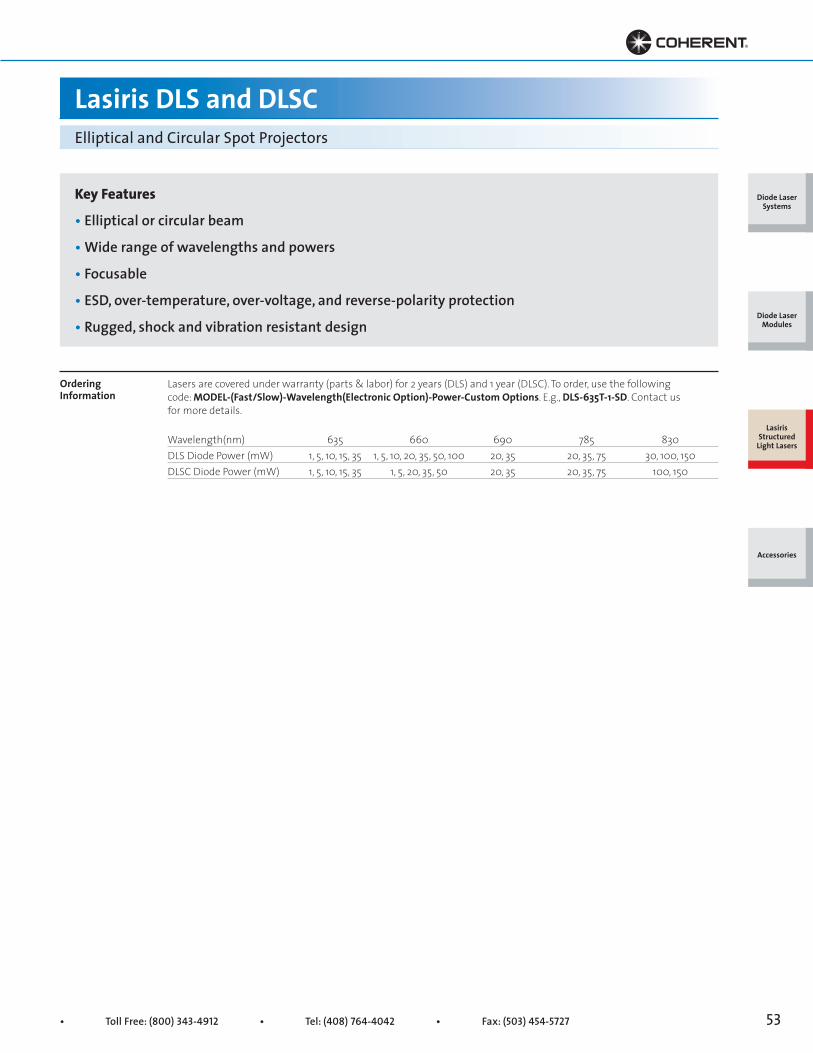
• Toll Free: (800) 343-4912 • Tel: (408) 764-4042 • Fax: (503) 454-5727 53
Lasiris DLS and DLSCElliptical and Circular Spot Projectors
Key Features
• Elliptical or circular beam
• Wide range of wavelengths and powers
• Focusable
• ESD, over-temperature, over-voltage, and reverse-polarity protection
• Rugged, shock and vibration resistant design
Ordering Information
Lasers are covered under warranty (parts & labor) for 2 years (DLS) and 1 year (DLSC). To order, use the following code: MODEL-(Fast/Slow)-Wavelength(Electronic Option)-Power-Custom Options. E.g., DLS-635T-1-SD. Contact us for more details.
Wavelength(nm) 635 660 690 785 830DLS Diode Power (mW) 1, 5, 10, 15, 35 1, 5, 10, 20, 35, 50, 100 20, 35 20, 35, 75 30, 100, 150DLSC Diode Power (mW) 1, 5, 10, 15, 35 1, 5, 20, 35, 50 20, 35 20, 35, 75 100, 150
Diode Laser Systems
Diode Laser Modules
Lasiris Structured
Light Lasers
Accessories
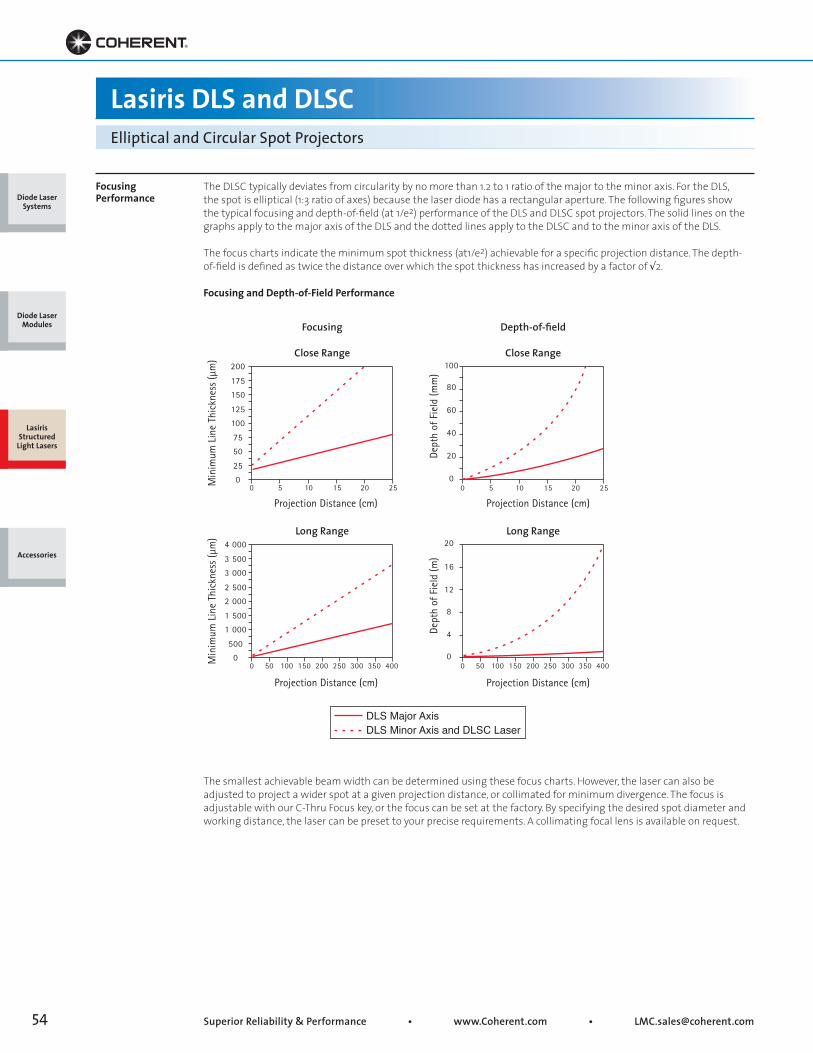
Superior Reliability & Performance • www.Coherent.com • [email protected]
Focusing Performance
The DLSC typically deviates from circularity by no more than 1.2 to 1 ratio of the major to the minor axis. For the DLS,the spot is elliptical (1:3 ratio of axes) because the laser diode has a rectangular aperture. The following figures showthe typical focusing and depth-of-field (at 1/e2) performance of the DLS and DLSC spot projectors. The solid lines on thegraphs apply to the major axis of the DLS and the dotted lines apply to the DLSC and to the minor axis of the DLS.
The focus charts indicate the minimum spot thickness (at1/e2) achievable for a specific projection distance. The depth-of-field is defined as twice the distance over which the spot thickness has increased by a factor of √2.
Focusing and Depth-of-Field Performance
The smallest achievable beam width can be determined using these focus charts. However, the laser can also beadjusted to project a wider spot at a given projection distance, or collimated for minimum divergence. The focus isadjustable with our C-Thru Focus key, or the focus can be set at the factory. By specifying the desired spot diameter andworking distance, the laser can be preset to your precise requirements. A collimating focal lens is available on request.
125
100
175
150
200
75
50
25
00 5 10 15 20 25M
inim
um L
ine
Thic
knes
s (µ
m)
Projection Distance (cm)
2 500
2 000
3 500
3 000
4 000
1 500
1 000
500
00 50 100 150 200 250 300 350 400M
inim
um L
ine
Thic
knes
s (µ
m)
Projection Distance (cm)
0
20
40
60
80
100
0 5 10 15 20 25
Dept
h of
Fie
ld (m
m)
Dept
h of
Fie
ld (m
)
Projection Distance (cm)
20
0
4
8
12
16
0 50 100 150 200 250 300 350 400
Projection Distance (cm)
Close Range
Long Range
Close Range
Long Range
Focusing Depth-of-field
Lasiris DLS and DLSCElliptical and Circular Spot Projectors
DLS Major AxisDLS Minor Axis and DLSC Laser
Diode Laser Systems
Diode Laser Modules
Lasiris Structured
Light Lasers
Accessories
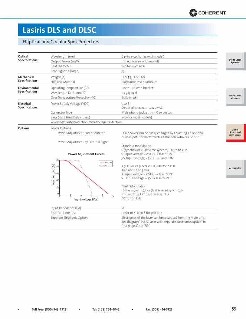
• Toll Free: (800) 343-4912 • Tel: (408) 764-4042 • Fax: (503) 454-5727 55
Lasiris DLS and DLSCElliptical and Circular Spot Projectors
OpticalSpecifications
MechanicalSpecifications
EnvironmentalSpecifications
ElectricalSpecifications
Options
Wavelength (nm) 635 to 1550 (varies with model)Output Power (mW) 1 to 150 (varies with model)Spot Diameter See focus chartsBore Sighting (mrad) <3
Weight (g) DLS: 54, DLSC: 60Housing Material Black anodized aluminum
Operating Temperature (°C) -10 to +48 with bracketWavelength Drift (nm/°C) 0.25 typicalOver-Temperature Protection (°C) Built-in: 48
Power Supply Voltage (VDC) 5 to 6 Optional 9, 12, 24 , 115/220 VACConnector Type Male phono-jack 3.5 mm Ø or customSlow Start Time Delay (μsec) 250 (for most models)Reverse-Polarity Protection, Over-Voltage Protection
Power Options Power Adjustment Potentiometer Laser power can be easily changed by adjusting an optional built-in potentiometer with a small screwdriver. Code “P”. Power Adjustment by External Signal Standard modulation S (synchro) or RS (reverse synchro): DC to 10 kHz S: Input voltage = 0VDC → laser “ON” RS: Input voltage = 5VDC → laser “ON”
T (TTL) or RT (Reverse TTL): DC to 10 kHz Transition 2 to 3 VDC T: Input voltage = 0VDC → laser “ON” RT: Input voltage = 5V → laser “ON”
“Fast” Modulation FS (fast synchro), FRS (fast reverse synchro) or FT (fast TTL0, FRT (fast reverse TTL) DC to 300 kHz Input Impedance (kW) >1Rise/Fall Time (μs) 10 for 10 KHz , 0.8 for 300 kHzSeparate Electronic Option Electronics of the laser can be separated from the main unit. See diagram “DLS/C laser with separate electronics option” in first page. Code “SD”.
100
80
60
40
20
00 1 2 3 4 5
Input voltage (VDC)
Pow
er o
utpu
t (%
)
TTL*
Standard
Power Adjustment Curves
Diode Laser Systems
Diode Laser Modules
Lasiris Structured
Light Lasers
Accessories

Superior Reliability & Performance • www.Coherent.com • [email protected]
ø
0.515 ± 0.015[13.08 ± 0.38]
4.11 ± 0.02[104.5 ± 0.5]
0.734 ± 0.005[18.64 ± 0.13]
ø 0.750 ± 0.005[19.05 ± 0.13]
POWER CABLE6 INCHES ± 0.5 [153 mm ± 13]
POWER CABLE18 INCHES ± 0.5 [457 mm ± 13]EXCLUDING CONNECTOR LENGTH
CONNECTOR MONOJACK3.5 mm
ø 0.750 ± 0.005[19.05 ± 0.13] 1.6 ± 0.2
[41 ± 5]ELECTRONIC
CLAMPINGAREA SWITCH
LED+5 VDC
GND
Lasiris GLLGreen Structured Light Pattern Generating Laser
Top View
Mechanical Specifications
Diode Laser Systems
Diode Laser Modules
Lasiris Structured
Light Lasers
Accessories
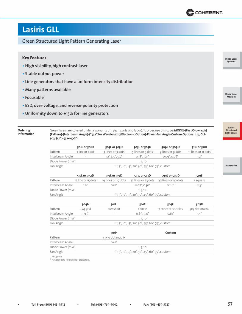
• Toll Free: (800) 343-4912 • Tel: (408) 764-4042 • Fax: (503) 454-5727 57
Lasiris GLLGreen Structured Light Pattern Generating Laser
Key Features
• High visibility, high contrast laser
• Stable output power
• Line generators that have a uniform intensity distribution
• Many patterns available
• Focusable
• ESD, over-voltage, and reverse-polarity protection
• Uniformity down to ±15% for line generators
Ordering Information
Green lasers are covered under a warranty of 1 year (parts and labor). To order, use this code: MODEL-(Fast/Slow axis)(Pattern)-(Interbeam Angle)-(“532” for Wavelength)(Electronic Option)-Power-Fan Angle-Custom Options. E.g., GLL-503L(1.2°)-532-1-5-SD.
501L or 501D 503L or 503D 505L or 505D 509L or 509D 511L or 511DPattern 1 line or 1 dot 3 lines or 3 dots 5 lines or 5 dots 9 lines or 9 dots 11 lines or 11 dotsInterbeam Angle1 - 1.2°, 4.0°, 9.2° 0.18°, 1.23° 0.09°, 0.06° 1.2°Diode Power (mW) 1, 5, 10Fan Angle 1°2, 5°, 10°, 15°, 20°, 30°, 45°, 60°, 75°, custom
515L or 5151D 519L or 519D 533L or 533D 599L or 599D 501SPattern 15 line or 15 dots 19 lines or 19 dots 33 lines or 33 dots 99 lines or 99 dots 1 squareInterbeam Angle1 1.8° 0.61° 0.07°, 0.30° 0.118° 2.3°Diode Power (mW) 1, 5, 10Fan Angle 1°2, 5°, 10°, 15°, 20°, 30°, 45°, 60°, 75°, custom
504G 501H 501C 507C 507XPattern 4x4 grid crosshair 1 circle 7 concentric cicles 7x7 dot matrixInterbeam Angle1 1.93° - 0.61°, 9.0° 0.61° 1.5°Diode Power (mW) 1, 5, 10Fan Angle 1°2, 5°, 10°, 15°, 20°, 30°, 45°, 60°, 75°, custom
501H Custom Pattern 19x19 dot matrix Interbeam Angle1 0.61° Diode Power (mW) 1, 5, 10Fan Angle 1°2, 5°, 10°, 15°, 20°, 30°, 45°, 60°, 75°, custom1 At 532 nm.2 Not standard for crosshair projectors.
Diode Laser Systems
Diode Laser Modules
Lasiris Structured
Light Lasers
Accessories

Superior Reliability & Performance • www.Coherent.com • [email protected]
0
25
50
75
100
125
6 8 10 12 14 16 18 20 22 24 26
150
Min
. Lin
e Th
ickn
ess
(µm
)
Projection Distance (cm)
05
1015202530354045
6 8 10 12 14 16 18 20 22 24 26
50
Min
. Lin
e Th
ickn
ess
(µm
)
Projection Distance (cm)
0
500
1000
1500
2000
2500
3000
0 50 100 150 200 250 300 350 400
3500
Min
. Lin
e Th
ickn
ess
(µm
)
Projection Distance (cm)
0
100
200
300
400
0 50 100 150 200 250 300
500
Min
. Lin
e Th
ickn
ess
(µm
)
Projection Distance (cm)
Lasiris GLLGreen Structured Light Pattern Generating Laser
Uniform Intensity
Focusing Performance
Laser line patterns are often generated by cylindrical optics that produce a Gaussian line profile with a bright centerand fading ends. Lasiris patented optics spread the light into an evenly illuminated line. The result is a crisp, uniformline with sharp ends.
Line Intensity Profile Along Line Length
The following figures show the typical focusing and depth-of-field performance of the Green laser projector. The focuscharts indicate the minimum line thickness (at 1/e2) achievable for a specific projection distance. The depth-of-field isdefined as twice the distance over which the thickness of the line has increased by a factor of √2.
Focusing and Depth-of-Field Performance
1 Typical profile.
Lasiris Non-Gaussian Line1
Focusing
Close Range
Long Range
Relative Intensity vs. Angular Position Along Line Length
Gaussian Line from Cylindrical Lens
Depth-of-field
Close Range
Long Range
0
0 2
0 4
0 6
0 8
10 8 6 4 2 0 2 4 6 8 10
1 0
Rel
ativ
e In
tens
ity
Relative Angular Position
0
0 2
0 4
0 6
0 8
10 8 6 4 2 0 2 4 6 8 10
1 0
Rel
ativ
e In
tens
ity
Relative Angular Position
Diode Laser Systems
Diode Laser Modules
Lasiris Structured
Light Lasers
Accessories
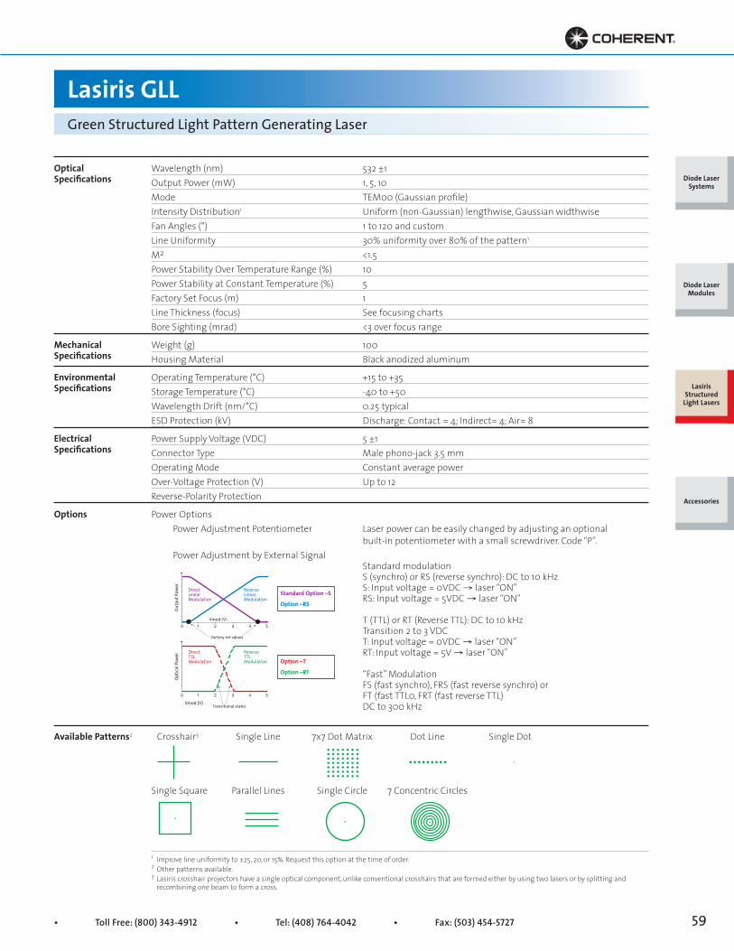
• Toll Free: (800) 343-4912 • Tel: (408) 764-4042 • Fax: (503) 454-5727 59
Lasiris GLLGreen Structured Light Pattern Generating Laser
OpticalSpecifications
Wavelength (nm) 532 ±1Output Power (mW) 1, 5, 10Mode TEM00 (Gaussian profile)Intensity Distribution1 Uniform (non-Gaussian) lengthwise, Gaussian widthwiseFan Angles (°) 1 to 120 and customLine Uniformity 30% uniformity over 80% of the pattern1
M2 <1.5Power Stability Over Temperature Range (%) 10Power Stability at Constant Temperature (%) 5Factory Set Focus (m) 1Line Thickness (focus) See focusing chartsBore Sighting (mrad) <3 over focus range
Weight (g) 100Housing Material Black anodized aluminum
Operating Temperature (°C) +15 to +35Storage Temperature (°C) -40 to +50Wavelength Drift (nm/°C) 0.25 typicalESD Protection (kV) Discharge: Contact = 4; Indirect= 4; Air= 8
Power Supply Voltage (VDC) 5 ±1Connector Type Male phono-jack 3.5 mmOperating Mode Constant average powerOver-Voltage Protection (V) Up to 12Reverse-Polarity Protection
Power Options Power Adjustment Potentiometer Laser power can be easily changed by adjusting an optional built-in potentiometer with a small screwdriver. Code “P”. Power Adjustment by External Signal Standard modulation S (synchro) or RS (reverse synchro): DC to 10 kHz S: Input voltage = 0VDC → laser “ON” RS: Input voltage = 5VDC → laser “ON”
T (TTL) or RT (Reverse TTL): DC to 10 kHz Transition 2 to 3 VDC T: Input voltage = 0VDC → laser “ON” RT: Input voltage = 5V → laser “ON”
“Fast” Modulation FS (fast synchro), FRS (fast reverse synchro) or FT (fast TTL0, FRT (fast reverse TTL) DC to 300 kHz
Crosshair3 Single Line 7x7 Dot Matrix Dot Line Single Dot
Single Square Parallel Lines Single Circle 7 Concentric Circles
1 Improve line uniformity to ±25, 20, or 15%. Request this option at the time of order. 2 Other patterns available. 3 Lasiris crosshair projectors have a single optical component, unlike conventional crosshairs that are formed either by using two lasers or by splitting and recombining one beam to form a cross.
MechanicalSpecifications
EnvironmentalSpecifications
ElectricalSpecifications
Options
Available Patterns2
ReverseTTLModulation
Vmod (V)0 1 2 3 4 5
DirectTTLModulation
Optic
al Po
wer
Transitional states
ReverseLinearModulation
Vmod (V)0 1 2 3 4 5
DirectLinearModulation
Outp
ut Po
wer
Factory set values
Standard Option –S
Option –RS
Option –T
Option –RT
Diode Laser Systems
Diode Laser Modules
Lasiris Structured
Light Lasers
Accessories
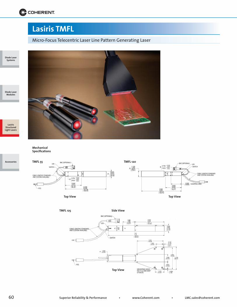
Superior Reliability & Performance • www.Coherent.com • [email protected]
0 8850 86522 4821 97
3 15080 01
2 96275 25
0 1640 1444 183 67
1 00025 40
1 00024 40Ø
MOUNTING HOLESM3 X 4.5 MM DEEP6 PLACES
1 27932 50
4 0594 039103 11102 60
1 6881 66842 8842 37
1 04026 42
0 0942 38
0 96124 42
3 62592 08
0 7500 748Ø
7 817 73198 44196 40
LED
SWITCH
BNC (OPTIONAL)
PCS
CABLE LENGTHS STANDARDAND CUSTOM AVAILABLE
6.5986.538167 58166 05
0.750 +0 0000 002
19.05 +0 000 05
Ø
2.6452.61567.1866.42
0.8750.87022.2222.10
Ø
PCS
BNC (OPTIONAL)
CABLE LENGTHS STANDARDAND CUSTOM AVAILABLE
LED
SWITCH0.750 +0 000
0 00219.05 +0 00
0 05Ø
3.0603.02077.7276.717 687
7 627195.25193.73
1.1051.09528.0727.81
Ø
2.00050.80 CLAMPING AREA
SWITCHLEDBNC (OPTIONAL)
CABLE LENGTHS STANDARDAND CUSTOM AVAILABLE
Lasiris TMFLMicro-Focus Telecentric Laser Line Pattern Generating Laser
Top View
Side View
Top ViewTop View
Mechanical Specifications
TMFL 55 TMFL 120
TMFL 125
Diode Laser Systems
Diode Laser Modules
Lasiris Structured
Light Lasers
Accessories
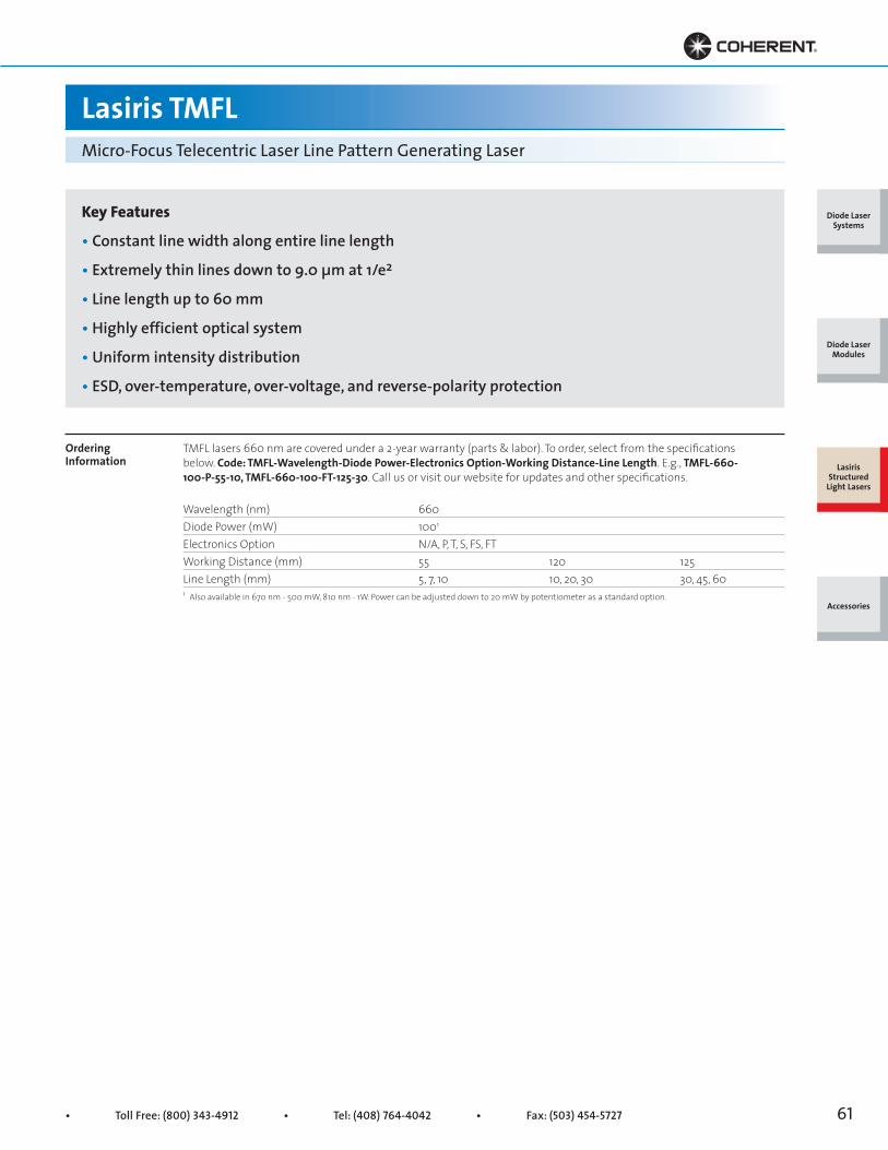
• Toll Free: (800) 343-4912 • Tel: (408) 764-4042 • Fax: (503) 454-5727 61
Lasiris TMFLMicro-Focus Telecentric Laser Line Pattern Generating Laser
Key Features
• Constant line width along entire line length
• Extremely thin lines down to 9.0 μm at 1/e2
• Line length up to 60 mm
• Highly efficient optical system
• Uniform intensity distribution
• ESD, over-temperature, over-voltage, and reverse-polarity protection
Ordering Information
TMFL lasers 660 nm are covered under a 2-year warranty (parts & labor). To order, select from the specifications below. Code: TMFL-Wavelength-Diode Power-Electronics Option-Working Distance-Line Length. E.g., TMFL-660-100-P-55-10, TMFL-660-100-FT-125-30. Call us or visit our website for updates and other specifications.
Wavelength (nm) 660Diode Power (mW) 1001
Electronics Option N/A, P, T, S, FS, FTWorking Distance (mm) 55 120 125Line Length (mm) 5, 7, 10 10, 20, 30 30, 45, 601 Also available in 670 nm - 500 mW, 810 nm - 1W. Power can be adjusted down to 20 mW by potentiometer as a standard option.
Diode Laser Systems
Diode Laser Modules
Lasiris Structured
Light Lasers
Accessories
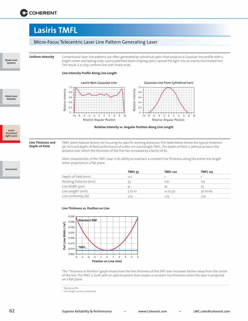
Superior Reliability & Performance • www.Coherent.com • [email protected]
0.005-5 -4 -3 -2 -1 0 1 2 3 4 5
0.010
0.015
0.020
0.025
0.030
0.035
0.040
Full
Line
Wid
th (1
/e2 )
Position on Line (mm)
TMFL
Standard SNF
Lasiris TMFLMicro-Focus Telecentric Laser Line Pattern Generating Laser
Uniform Intensity
Line Thickness and Depth-of-Field
Conventional laser line patterns are often generated by cylindrical optics that produce a Gaussian line profile with abright center and fading ends. Lasiris patented beam shaping optics spread the light into an evenly illuminated line.The result is a crisp, uniform line with sharp ends.
Line Intensity Profile Along Line Length
TMFL lasers feature factory-set focusing for specific working distances. The table below shows the typical thickness (at 1/e2) and depth-of-field performance of a 660 nm wavelength TMFL. The depth-of-field is defined as twice thedistance over which the thickness of the line has increased by a factor of √2.
Main characteristic of the TMFL laser is its ability to maintain a constant line thickness along the entire line lengthwhen projected on a flat plane.
TMFL 55 TMFL 120 TMFL 125Depth-of-Field (mm) 0.2 1 1Working Distance (mm) 55 120 125Line Width (μm) 9 25 25Line Length2 (mm) 5 to 10 10 to 30 30 to 60Line Uniformity (%) <_25 <_25 <_25
Line Thickness vs. Position on Line
The “Thickness vs Position” graph shows how the line thickness of the SNF laser increases farther away from the centerof the line. The TMFL is built with an optical system that creates a constant line thickness when the laser is projectedon a flat plane.
1 Typical profile.2 Line length can be customized.
1.0
0.8
0.6
0.4
0.2
0-10 -8 -6 -4 -2 0 2 4 6 8 10
Rela
tive
Inte
nsity
Relative Angular Position
1.0
0.8
0.6
0.4
0.2
0-10 -8 -6 -4 -2 0 2 4 6 8 10
Rela
tive
Inte
nsity
Relative Angular Position
Lasiris Non-Gaussian Line1
Relative Intensity vs. Angular Position Along Line Length
Gaussian Line from Cylindrical Lens
Diode Laser Systems
Diode Laser Modules
Lasiris Structured
Light Lasers
Accessories
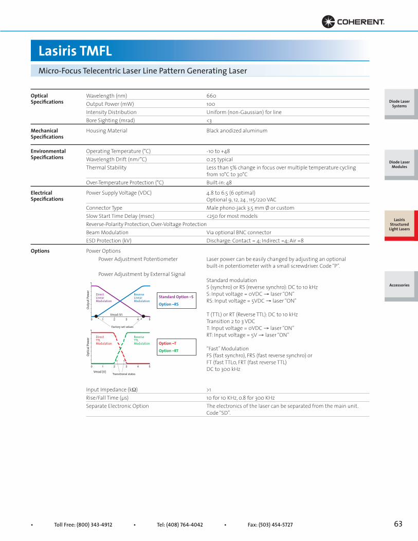
• Toll Free: (800) 343-4912 • Tel: (408) 764-4042 • Fax: (503) 454-5727 63
Lasiris TMFLMicro-Focus Telecentric Laser Line Pattern Generating Laser
OpticalSpecifications
EnvironmentalSpecifications
MechanicalSpecifications
ElectricalSpecifications
Wavelength (nm) 660Output Power (mW) 100Intensity Distribution Uniform (non-Gaussian) for lineBore Sighting (mrad) <3
Housing Material Black anodized aluminum
Operating Temperature (°C) -10 to +48Wavelength Drift (nm/°C) 0.25 typicalThermal Stability Less than 5% change in focus over multiple temperature cycling from 10°C to 30°COver-Temperature Protection (°C) Built-in: 48
Power Supply Voltage (VDC) 4.8 to 6.5 (6 optimal) Optional 9, 12, 24 , 115/220 VACConnector Type Male phono-jack 3.5 mm Ø or customSlow Start Time Delay (msec) <250 for most modelsReverse-Polarity Protection, Over-Voltage ProtectionBeam Modulation Via optional BNC connectorESD Protection (kV) Discharge: Contact = 4; Indirect =4; Air =8
Power Options Power Adjustment Potentiometer Laser power can be easily changed by adjusting an optional built-in potentiometer with a small screwdriver. Code “P”. Power Adjustment by External Signal Standard modulation S (synchro) or RS (reverse synchro): DC to 10 kHz S: Input voltage = 0VDC → laser “ON” RS: Input voltage = 5VDC → laser “ON”
T (TTL) or RT (Reverse TTL): DC to 10 kHz Transition 2 to 3 VDC T: Input voltage = 0VDC → laser “ON” RT: Input voltage = 5V → laser “ON”
“Fast” Modulation FS (fast synchro), FRS (fast reverse synchro) or FT (fast TTL0, FRT (fast reverse TTL) DC to 300 kHz
Input Impedance (kW) >1Rise/Fall Time (μs) 10 for 10 KHz, 0.8 for 300 KHzSeparate Electronic Option The electronics of the laser can be separated from the main unit. Code “SD”.
ReverseTTLModulation
Vmod (V)0 1 2 3 4 5
DirectTTLModulation
Optic
al Po
wer
Transitional states
ReverseLinearModulation
Vmod (V)0 1 2 3 4 5
DirectLinearModulation
Outp
ut Po
wer
Factory set values
Standard Option –S
Option –RS
Option –T
Option –RT
Diode Laser Systems
Diode Laser Modules
Lasiris Structured
Light Lasers
Accessories
Options
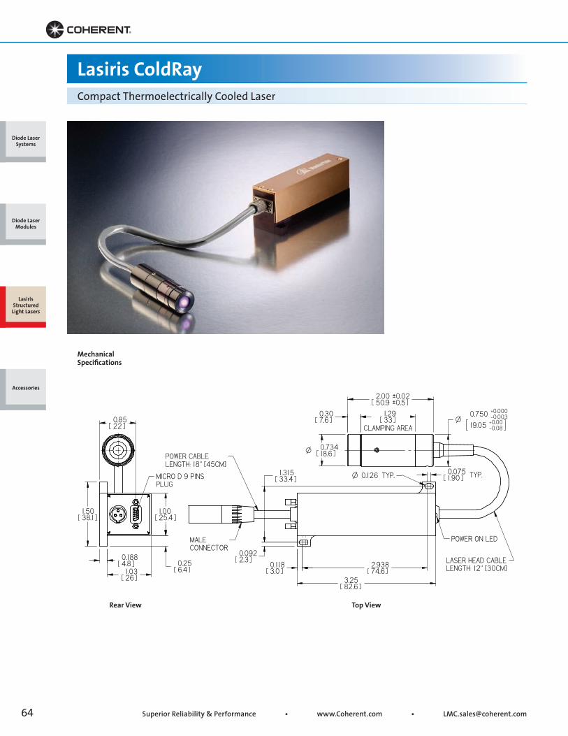
Superior Reliability & Performance • www.Coherent.com • [email protected]
Lasiris ColdRayCompact Thermoelectrically Cooled Laser
Top ViewRear View
Mechanical Specifications
Diode Laser Systems
Diode Laser Modules
Lasiris Structured
Light Lasers
Accessories

• Toll Free: (800) 343-4912 • Tel: (408) 764-4042 • Fax: (503) 454-5727 65
Lasiris ColdRayCompact Thermoelectrically Cooled Laser
Key Features
• 375 nm, 405 nm, 445 nm, 473 nm, 640 nm, 660 nm
• Excellent wavelength and power stability
• Excellent pointing stability
• Compatible with standard 1D and 2D flat top projector
• Extended lifetime
• Analog and digital modulation
• Circular models available
• Focusable
Ordering Information
Compatible with Micro Flat Top Generators
To order, use the following code: MODEL-(Fast/Slow axis)(Pattern)-(Interbeam Angle)-(Wavelength)(Electronic Option)-Power-Fan Angle-Custom Options. E.g., CR-501L-405S-60-20. Call us or visit our website for available optical patterns such as Flat-Top and diffractive optics.
Wavelength (nm) 375 405 445 473 640 660Diode Power (mW) 20 5, 10, 201, 30, 40, 50 20 5, 10, 35, 50, 601, 80, 1051, 120 35, 80 100, 1501
Electronics Option S, T, RS, RT1 No internal photodiode.
Flat Top 2D
Flat Top 1D
Flat Top Matrix 2D
Flat Top Matrix 1D
Horizontalwidth(μm @ 1/e2)60
Verticalwidth(μm @ 1/e2)13
Horizontalwidth(μm @ 1/e2)Total4800Individual600
Verticalwidth(μm @ 1/e2)Total5500Individual200
Horizontalwidth(μm @ 1/e2)Total200
Verticalwidth(μm @ 1/e2)Total250Individual10
Horizontalwidth(μm @ 1/e2)200
Verticalwidth(μm @ 1/e2)600
Diode Laser Systems
Diode Laser Modules
Lasiris Structured
Light Lasers
Accessories
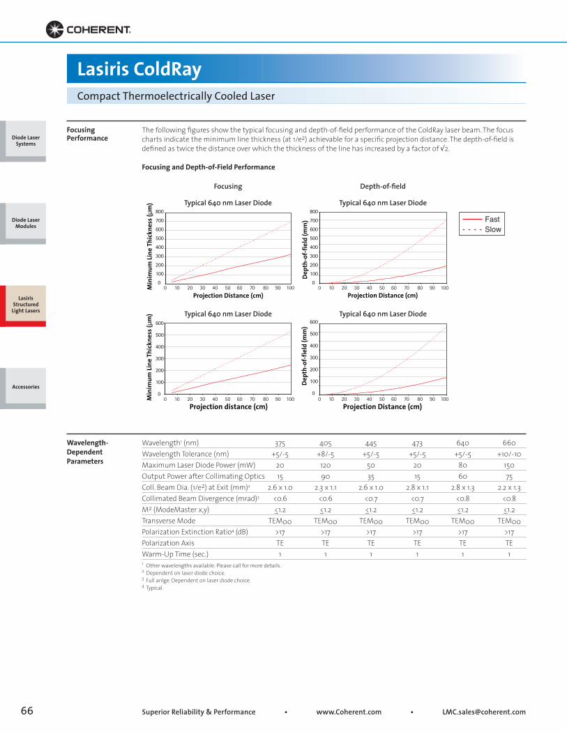
Superior Reliability & Performance • www.Coherent.com • [email protected]
Projection Distance (cm)De
pth-
of-f
ield
(mm
)
0
100
200
300
400
500
600
700
800
Projection Distance (cm)
Min
imum
Line
Thi
ckne
ss (μ
m)
0 10 20 30 40 50 60 70 80 90 1000
100
200
300
400
500
600
700
800
0 10 20 30 40 50 60 70 80 90 100
0
100
200
300
400
500
600
0 10 20 30 40 50 60 70 80 90 1000
100
200
300
400
500
600
0 10 20 30 40 50 60 70 80 90 100
Projection Distance (cm)
Dept
h-of
-fie
ld (m
m)
Projection distance (cm)
Min
imum
Line
Thi
ckne
ss (μ
m)
Focusing Performance
Wavelength- Dependent Parameters
The following figures show the typical focusing and depth-of-field performance of the ColdRay laser beam. The focuscharts indicate the minimum line thickness (at 1/e2) achievable for a specific projection distance. The depth-of-field isdefined as twice the distance over which the thickness of the line has increased by a factor of √2.
Focusing and Depth-of-Field Performance
Wavelength1 (nm) 375 405 445 473 640 660Wavelength Tolerance (nm) +5/-5 +8/-5 +5/-5 +5/-5 +5/-5 +10/-10Maximum Laser Diode Power (mW) 20 120 50 20 80 150Output Power after Collimating Optics 15 90 35 15 60 75Coll. Beam Dia. (1/e2) at Exit (mm)2 2.6 x 1.0 2.3 x 1.1 2.6 x 1.0 2.8 x 1.1 2.8 x 1.3 2.2 x 1.3Collimated Beam Divergence (mrad)3 <0.6 <0.6 <0.7 <0.7 <0.8 <0.8M2 (ModeMaster x,y) <_1.2 <_1.2 <_1.2 <_1.2 <_1.2 <_1.2Transverse Mode TEM00 TEM00 TEM00 TEM00 TEM00 TEM00Polarization Extinction Ratio4 (dB) >17 >17 >17 >17 >17 >17Polarization Axis TE TE TE TE TE TEWarm-Up Time (sec.) 1 1 1 1 1 11 Other wavelengths available. Please call for more details.2 Dependent on laser diode choice.3 Full anlge. Dependent on laser diode choice.4 Typical.
Lasiris ColdRayCompact Thermoelectrically Cooled Laser
Typical 640 nm Laser Diode
Typical 640 nm Laser Diode
Focusing
Typical 640 nm Laser Diode
Typical 640 nm Laser Diode
Depth-of-field
FastSlow
Diode Laser Systems
Diode Laser Modules
Lasiris Structured
Light Lasers
Accessories
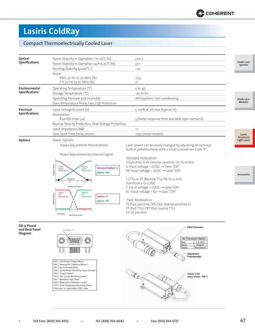
• Toll Free: (800) 343-4912 • Tel: (408) 764-4042 • Fax: (503) 454-5727 67
PIN 1 TEC Control Voltage (Black*)PIN 2 Reserved for Calibration (Brown*)PIN 3 Not Connected (Red*)PIN 4 Current/Power Monitoring Output (Orange*)PIN 5 Ground (Yellow*)PIN 6 TEC Current Monitoring (Green*)PIN 7 Modulation Input (Blue*)PIN 8 Reserved for Calibration (Violet*)PIN 9 Diode Temperature Monitoring (Gray*)*Wire color on optional Micro DB 9 cable
Yellow LED(laser diode “ON”)
DB-9 Connector
AdjustmentPotentiometer
No Connector OptionRedBlackGreen
+ 5 VDCGround
Modulation
OpticalSpecifications
EnvironmentalSpecifications
ElectricalSpecifications
Options
DB-9 Pinout and Back Panel Diagram
Power Stability in Operation 1 hr, 25°C (%) <_±0.5Power Stability in Operation 24 hrs, 25°C (%) <_±1Pointing Stability (μrad/°C ) <10Noise RMS, 20 Hz to 20 MHz (%) <0.5 P-P, 20 Hz to 20 MHz (%) <1
Operating Temperature (°C) 0 to 40Storage Temperature (°C) -20 to 60Operating Pressure and Humidity Atmospheric/non-condensingOver-Temperature Protection, ESD Protection
Input Voltage/Current (V) 5 ±10% at 2A max (typical 1A)Modulation Rise/fall time (μs) 5 (faster response time available upon demand)Reverse-Polarity Protection, Over-Voltage ProtectionInput Impedance (kW) >1Slow Start Time Delay (msec) <250 (most models)
Power Options Power Adjustment Potentiometer Laser power can be easily changed by adjusting an optional built-in potentiometer with a small screwdriver. Code “P”. Power Adjustment by External Signal Standard modulation S (synchro) or RS (reverse synchro): DC to 10 kHz S: Input voltage = 0VDC → laser “ON” RS: Input voltage = 5VDC → laser “ON”
T (TTL) or RT (Reverse TTL): DC to 10 kHz Transition 2 to 3 VDC T: Input voltage = 0VDC → laser “ON” RT: Input voltage = 5V → laser “ON”
“Fast” Modulation FS (fast synchro), FRS (fast reverse synchro) or FT (fast TTL0, FRT (fast reverse TTL) DC to 300 kHz
Lasiris ColdRayCompact Thermoelectrically Cooled Laser
ReverseTTLModulation
Vmod (V)0 1 2 3 4 5
DirectTTLModulation
Optic
al Po
wer
Transitional states
ReverseLinearModulation
Vmod (V)0 1 2 3 4 5
DirectLinearModulation
Outp
ut Po
wer
Factory set values
Standard Option –S
Option –RS
Option –T
Option –RT
Diode Laser Systems
Diode Laser Modules
Lasiris Structured
Light Lasers
Accessories
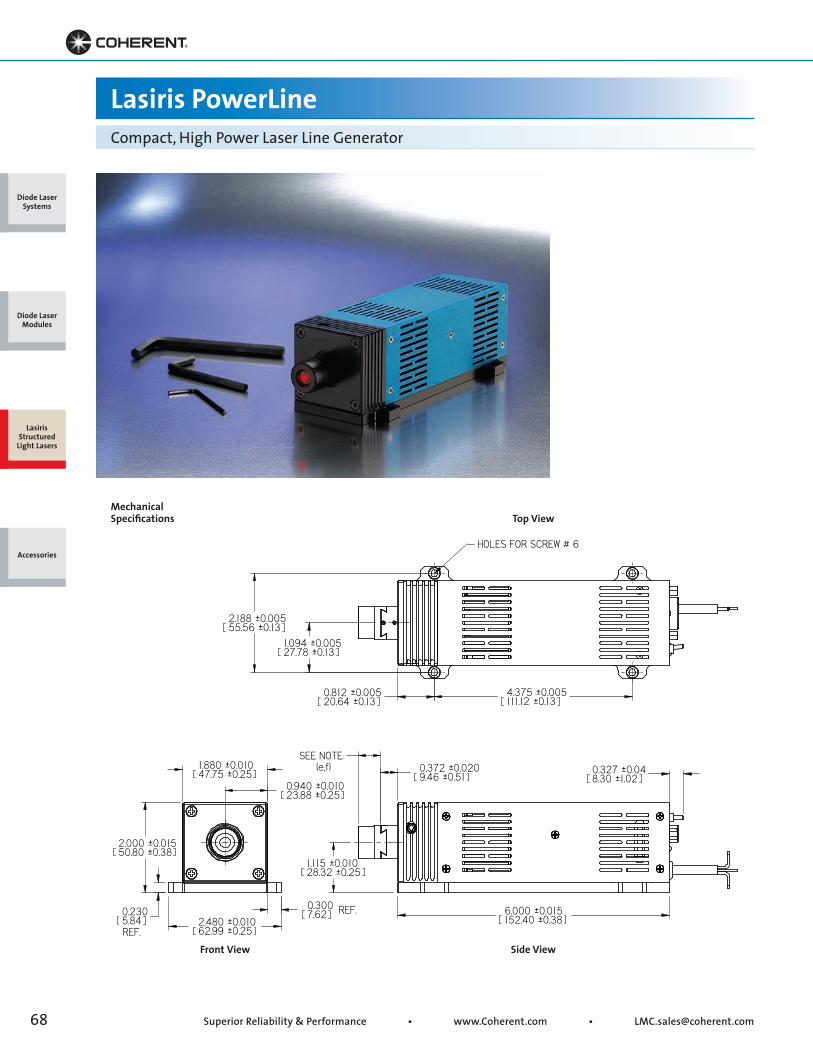
Superior Reliability & Performance • www.Coherent.com • [email protected]
Lasiris PowerLineCompact, High Power Laser Line Generator
Top View
Side ViewFront View
Mechanical Specifications
Diode Laser Systems
Diode Laser Modules
Lasiris Structured
Light Lasers
Accessories
• Toll Free: (800) 343-4912 • Tel: (408) 764-4042 • Fax: (503) 454-5727 69
Lasiris PowerLineCompact, High Power Laser Line Generator
Key Features
• High power laser in a compact package
• Uniform intensity distribution for laser line generators
• Focusable
• High pointing stability
• Over-voltage, reverse-polarity, over-heating and ESD protection
• Compatible with standard pattern generators
Ordering Information
For all PowerLine series, the warranty period shall be one (1) year. To order, use the following code: MODEL-(Fast/Slow axis)(Pattern)-(Interbeam Angle)-(Wavelength)(Electronic Option)-Power-Fan Angle-Custom Options. E.g., PL-501L-670T-500-45°. Note that the projected fan angle may be less than the lens fan angle.
PowerLine UV PowerLine Violet PowerLine Blue PowerLine Red PowerLine IRWavelength1 (nm) 375 405 445 670 810Diode Power (mW) 150 600 500 500 1000, 2000Beam Power (mW) 112 450 375 375 750, 1500Electrical Power 12/24VDC, 3A2 12/24VDC, 3A2 12/24VDC, 3A2 5VDC, 2A2 5VDC, 3A, 4A2
Lens Fan Angle 10°, 15°, 20°, 30°, 40°, 45°, 55°,60°, 75°, custom1 ±10 nm.2 At ambient temperature of 23°C.
Diode Laser Systems
Diode Laser Modules
Lasiris Structured
Light Lasers
Accessories

Superior Reliability & Performance • www.Coherent.com • [email protected]
0 50 100 150 200
Beam
Wid
th (µ
m)
Distance (mm)
1 600
1 200
800
400
00 1000 2000 3000 4000
Beam
Wid
th (µ
m)
Distance (mm)
0
20
40
60
80
Dept
h of
Fie
ld (m
m)
Dept
h-of
-Fie
ld (m
m)
0 1000 2000 3000 4000
Distance (mm)
4000
3000
2000
1000
0
12
10
8
6
4
2
00 50 100 150 200
Laser diode: 810 nm / 1 W
Laser diode: 810 nm / 1 W
Laser diode: 810 nm / 1 W
Laser diode: 810 nm / 1 W
Note: For distances below 50 mm, call usDistance (mm)
Note: For distances below 50 mm, call us
Uniform Intensity
Focusing Performance
Conventional laser line patterns are often generated by cylindrical optics that produce a Gaussian line profile with abright center and fading ends. Lasiris patented beam shaping optics spread the light into an evenly illuminated line.The result is a crisp, uniform line with sharp ends.
Line Intensity Profile Along Line Length
The following figures show the typical focusing and depth-of-field performance (at 1/e2) performance. LasirisPowerLine lasers are focusable and can be adjusted by the user to produce a focused line at any projection distance.In addition, the line can be collimated so that its thickness remains fairly constant over a long projection distance.
Focusing and Depth-of-Field Performance
1 Typical profile.
1.0
0.8
0.6
0.4
0.2
0-10 -8 -6 -4 -2 0 2 4 6 8 10
Rela
tive
Inte
nsity
Relative Angular Position
1.0
0.8
0.6
0.4
0.2
0-10 -8 -6 -4 -2 0 2 4 6 8 10
Rela
tive
Inte
nsity
Relative Angular Position
Focusing
Long Range
Depth-of-field
Long Range
Lasiris Non-Gaussian Line1
Relative Intensity vs. Angular Position Along Line Length
Gaussian Line from Cylindrical Lens
Lasiris PowerLineCompact, High Power Laser Line Generator
Diode Laser Systems
Diode Laser Modules
Lasiris Structured
Light Lasers
Accessories
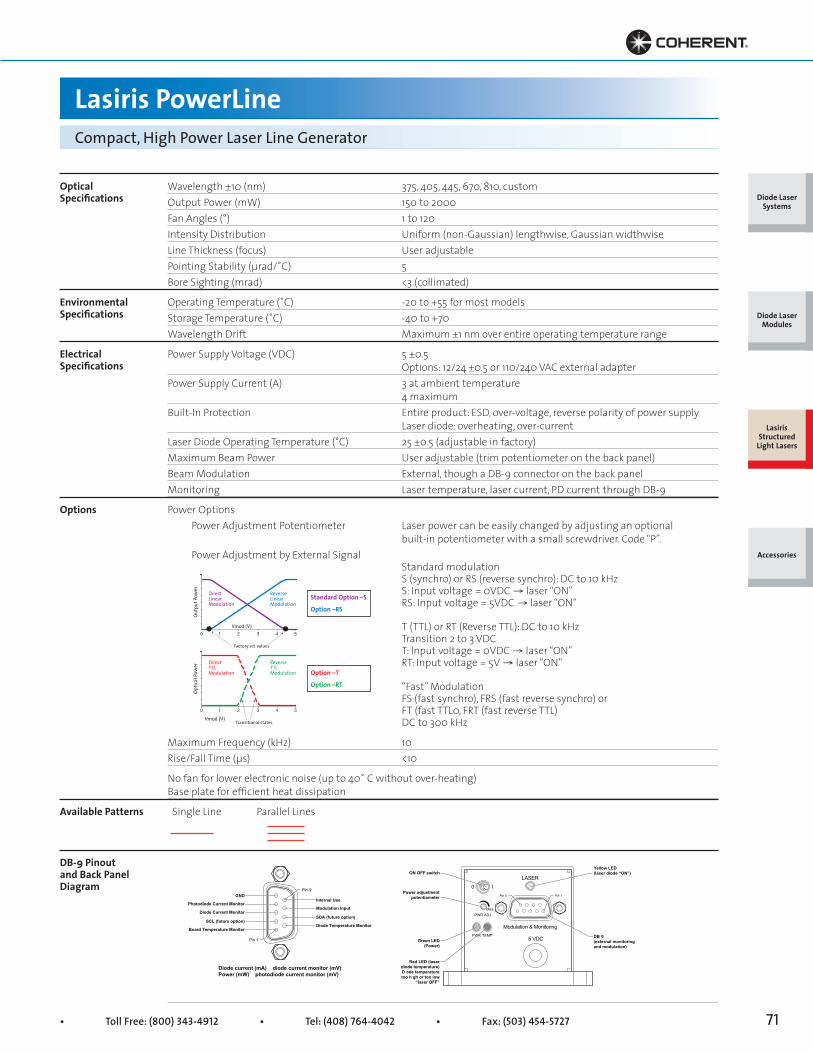
• Toll Free: (800) 343-4912 • Tel: (408) 764-4042 • Fax: (503) 454-5727 71
OpticalSpecifications
EnvironmentalSpecifications
ElectricalSpecifications
Available Patterns
DB-9 Pinout and Back Panel Diagram
Wavelength ±10 (nm) 375, 405, 445, 670, 810, customOutput Power (mW) 150 to 2000Fan Angles (°) 1 to 120Intensity Distribution Uniform (non-Gaussian) lengthwise, Gaussian widthwiseLine Thickness (focus) User adjustablePointing Stability (μrad/˚C) 5 Bore Sighting (mrad) <3 (collimated)
Operating Temperature (˚C) -20 to +55 for most modelsStorage Temperature (˚C) -40 to +70Wavelength Drift Maximum ±1 nm over entire operating temperature range
Power Supply Voltage (VDC) 5 ±0.5 Options: 12/24 ±0.5 or 110/240 VAC external adapterPower Supply Current (A) 3 at ambient temperature 4 maximumBuilt-In Protection Entire product: ESD, over-voltage, reverse polarity of power supply Laser diode: overheating, over-currentLaser Diode Operating Temperature (°C) 25 ±0.5 (adjustable in factory)Maximum Beam Power User adjustable (trim potentiometer on the back panel)Beam Modulation External, though a DB-9 connector on the back panelMonitoring Laser temperature, laser current, PD current through DB-9
Power Options Power Adjustment Potentiometer Laser power can be easily changed by adjusting an optional built-in potentiometer with a small screwdriver. Code “P”. Power Adjustment by External Signal Standard modulation S (synchro) or RS (reverse synchro): DC to 10 kHz S: Input voltage = 0VDC → laser “ON” RS: Input voltage = 5VDC → laser “ON”
T (TTL) or RT (Reverse TTL): DC to 10 kHz Transition 2 to 3 VDC T: Input voltage = 0VDC → laser “ON” RT: Input voltage = 5V → laser “ON”
“Fast” Modulation FS (fast synchro), FRS (fast reverse synchro) or FT (fast TTL0, FRT (fast reverse TTL) DC to 300 kHz
Maximum Frequency (kHz) 10Rise/Fall Time (μs) <10
No fan for lower electronic noise (up to 40˚ C without over-heating)Base plate for efficient heat dissipation
Single Line Parallel Lines
Lasiris PowerLineCompact, High Power Laser Line Generator
Modu ati n & Mon tor nWR E
5 VDC
Power a ju ment
Gr en LEDP
Red LE ( aser p
GND
Photodiode Current Monitor
Diode Current Monitor
SCL (future option)
Board Temperature Monitor
Internal Use
Modulation Input
SDA (future option)
Diode Temperature Monitor
Diode current (mA) diode current monitor (mV)Power (mW) photodiode current monitor (mV)
Pin 1
Pin 9
in
0 ILASER
Modulation & MonitoringPWR TEMP
PWR ADJMax
5 VDC
Yellow LED(laser diode “ON”)
DB 9(external monitoringand modulation)
ON OFF switch
Power adjustmentpotentiometer
Green LED(Power)
Red LED (laserdiode temperature)D ode temperaturetoo h gh or too low
“laser OFF”
Pin 1Pin 9
Diode Laser Systems
Diode Laser Modules
Lasiris Structured
Light Lasers
Accessories
Options
ReverseTTLModulation
Vmod (V)0 1 2 3 4 5
DirectTTLModulation
Optic
al Po
wer
Transitional states
ReverseLinearModulation
Vmod (V)0 1 2 3 4 5
DirectLinearModulation
Outp
ut Po
wer
Factory set values
Standard Option –S
Option –RS
Option –T
Option –RT

Superior Reliability & Performance • www.Coherent.com • [email protected]
Lasiris Green PowerLineThermoelectrically Cooled Green Laser
Top View
Side ViewFront View
Mechanical Specifications
Diode Laser Systems
Diode Laser Modules
Lasiris Structured
Light Lasers
Accessories

• Toll Free: (800) 343-4912 • Tel: (408) 764-4042 • Fax: (503) 454-5727 73
Lasiris Green PowerLineThermoelectrically Cooled Green Laser
Key Features
• High power, high visibility, high contrast laser
• External focusing
• Uniform, non-Gaussian intensity distribution along the line
• ESD, over-temperature, and reverse-polarity protection
Ordering Information
Green PowerLine lasers are covered under a one-year warranty (parts and labor). MODEL-(Fast/Slow axis)(Pattern)-(Interbeam Angle)-(“532” for Wavelength)(Electronic Option)-Power-Fan Angle-Custom Options. E.g., GPL- 503L(1.2°)-532-100-5°. Contact us for more details.
501L or 501D 501H 503L or 503D 505L or 505D 509L or 509DPattern 1 line or 1 dot crosshair 3 lines or 3 dots 5 lines or 5 dots 9 lines or 9 dotsInterbeam Angle1 - - 1.2°, 3.95°·, 9.23° 0.18°, 1.23° 0.09°, 0.06°Diode Power (mW) 50, 100, 150, 200Fan Angle 1°2, 5°, 10°, 15°, 20°, 30°, 45°, 60°, 75°, custom3
511L or 511D 515L or 5151D 519L or 519D 533L or 533D 599L or 599DPattern 11 lines or 11 dots 15 lines or 15 dots 19 lines or 19 dots 33 lines or 33 dots 99 lines or 99 dotsInterbeam Angle1 1.2° 1.8° 0.61° 0.07°, 0.30° 0.118°Diode Power (mW) 50, 100, 150, 200Fan Angle 1°2, 5°, 10°, 15°, 20°, 30°, 45°, 60°, 75°, custom3
1 At 532 nm.2 Not standard for crosshair projectors.3 Custom (please call us).
Diode Laser Systems
Diode Laser Modules
Lasiris Structured
Light Lasers
Accessories
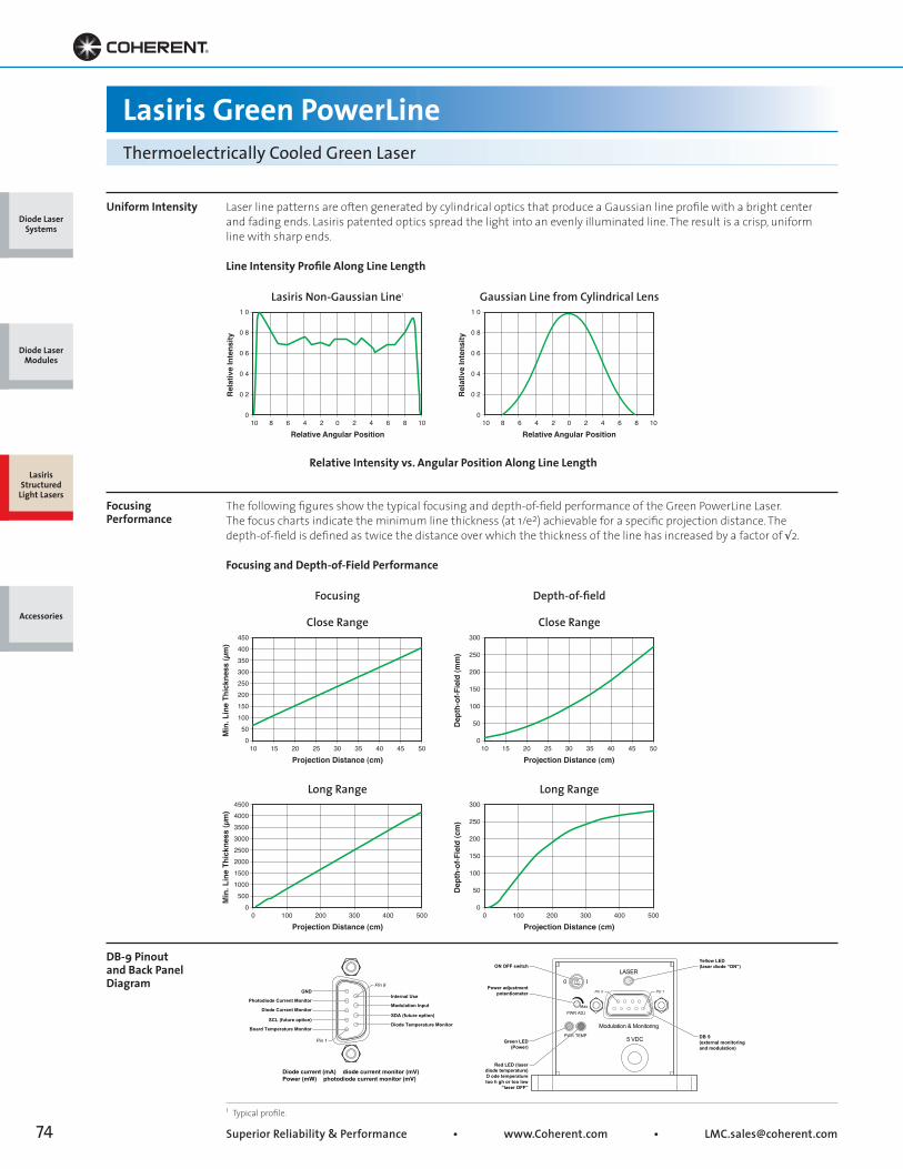
Superior Reliability & Performance • www.Coherent.com • [email protected]
DB-9 Pinout and Back Panel Diagram
GND
Photodiode Current Monitor
Diode Current Monitor
SCL (future option)
Board Temperature Monitor
Internal Use
Modulation Input
SDA (future option)
Diode Temperature Monitor
Diode current (mA) diode current monitor (mV)Power (mW) photodiode current monitor (mV)
Pin 1
Pin 9
0 ILASER
Modulation & MonitoringPWR TEMP
PWR ADJMax
5 VDC
Yellow LED(laser diode “ON”)
DB 9(external monitoringand modulation)
ON OFF switch
Power adjustmentpotentiometer
Green LED(Power)
Red LED (laserdiode temperature)D ode temperaturetoo h gh or too low
“laser OFF”
Pin 1Pin 9
050
100150200250300350400
10 15 20 25 30 35 40 45 50
450
Min
. Lin
e Th
ickn
ess
(µm
)
Projection Distance (cm)
0
50
100
150
200
250
10 15 20 25 30 35 40 45 50
300
Dep
th-o
f-Fie
ld (m
m)
Projection Distance (cm)
0500
1000150020002500300035004000
0 100 200 300 400 500
4500
Min
. Lin
e Th
ickn
ess
(µm
)
Projection Distance (cm)
0
50
100
150
200
250
0 100 200 300 400 500
300
Dep
th-o
f-Fie
ld (c
m)
Projection Distance (cm)
Lasiris Green PowerLineThermoelectrically Cooled Green Laser
Uniform Intensity
Focusing Performance
Laser line patterns are often generated by cylindrical optics that produce a Gaussian line profile with a bright centerand fading ends. Lasiris patented optics spread the light into an evenly illuminated line. The result is a crisp, uniformline with sharp ends.
Line Intensity Profile Along Line Length
The following figures show the typical focusing and depth-of-field performance of the Green PowerLine Laser.The focus charts indicate the minimum line thickness (at 1/e2) achievable for a specific projection distance. Thedepth-of-field is defined as twice the distance over which the thickness of the line has increased by a factor of √2.
Focusing and Depth-of-Field Performance
1 Typical profile.
Lasiris Non-Gaussian Line1
Focusing
Close Range
Long Range
Relative Intensity vs. Angular Position Along Line Length
Gaussian Line from Cylindrical Lens
Depth-of-field
Close Range
Long Range
0
0 2
0 4
0 6
0 8
10 8 6 4 2 0 2 4 6 8 10
1 0
Rel
ativ
e In
tens
ity
Relative Angular Position
0
0 2
0 4
0 6
0 8
10 8 6 4 2 0 2 4 6 8 10
1 0
Rel
ativ
e In
tens
ity
Relative Angular Position
Diode Laser Systems
Diode Laser Modules
Lasiris Structured
Light Lasers
Accessories
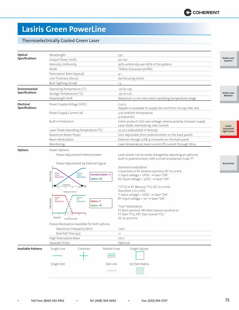
• Toll Free: (800) 343-4912 • Tel: (408) 764-4042 • Fax: (503) 454-5727 75
Lasiris Green PowerLineThermoelectrically Cooled Green Laser
OpticalSpecifications
EnvironmentalSpecifications
ElectricalSpecifications
Options
Wavelength 532Output Power (mW) 50, 100Intensity Uniformity 30% uniformity over 80% of the patternMode TEM00 (Gaussian profile)Polarization Ratio (typical) 4:1 Line Thickness (focus) See focusing chartsBore Sighting (mrad) <3
Operating Temperature (˚C) -20 to +45Storage Temperature (˚C) -40 to +70Wavelength Drift Maximum ±1 nm over entire operating temperature range
Power Supply Voltage (VDC) 5 ±0.5 Adapter is available to supply the unit from 110/240 VAC linePower Supply Current (A) 3 at ambient temperature 4 maximumBuilt-In Protection Entire product: ESD, over-voltage, reverse polarity of power supply Laser diode: overheating, over-currentLaser Diode Operating Temperature (°C) 25 ±0.5 (adjustable in factory)Maximum Beam Power User adjustable (trim potentiometer on the back panel)Beam Modulation External, though a DB-9 connector on the back panelMonitoring Laser temperature, laser current, PD current through DB-9
Power Options Power Adjustment Potentiometer Laser power can be easily changed by adjusting an optional built-in potentiometer with a small screwdriver. Code “P”. Power Adjustment by External Signal Standard modulation S (synchro) or RS (reverse synchro): DC to 10 kHz S: Input voltage = 0VDC → laser “ON” RS: Input voltage = 5VDC → laser “ON”
T (TTL) or RT (Reverse TTL): DC to 10 kHz Transition 2 to 3 VDC T: Input voltage = 0VDC → laser “ON” RT: Input voltage = 5V → laser “ON”
“Fast” Modulation FS (fast synchro), FRS (fast reverse synchro) or FT (fast TTL0, FRT (fast reverse TTL) DC to 300 kHz
Pulsed Modulation Available for both options Maximum Frequency (kHz) <100 Rise/Fall Time (μs) <1High Polarization Ratio 100:1Separate Driver Optional
Single Line Crosshair Parallel Lines Single Square
Single Dot Dot Line 7x7 Dot Matrix
Available Patterns
Diode Laser Systems
Diode Laser Modules
Lasiris Structured
Light Lasers
Accessories
ReverseTTLModulation
Vmod (V)0 1 2 3 4 5
DirectTTLModulation
Optic
al Po
wer
Transitional states
ReverseLinearModulation
Vmod (V)0 1 2 3 4 5
DirectLinearModulation
Outp
ut Po
wer
Factory set values
Standard Option –S
Option –RS
Option –T
Option –RT
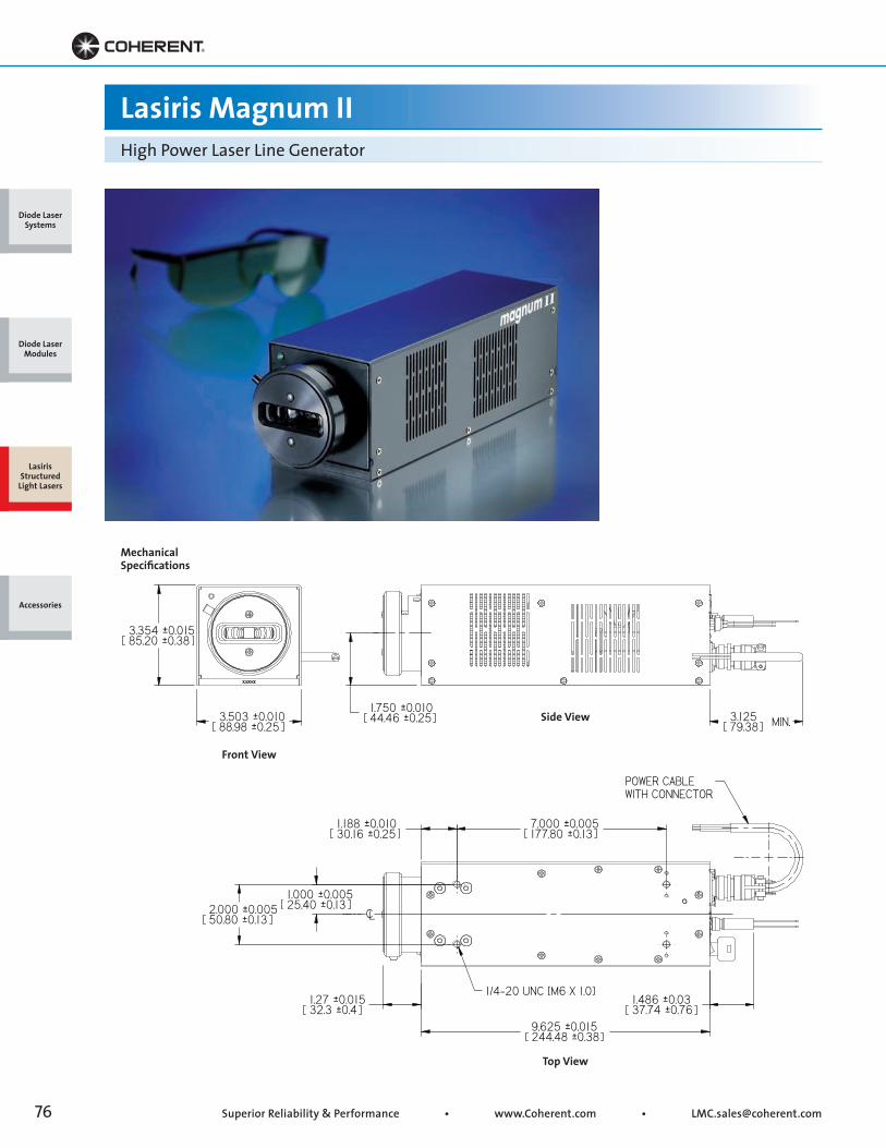
Superior Reliability & Performance • www.Coherent.com • [email protected]
Lasiris Magnum IIHigh Power Laser Line Generator
Top View
Side View
Front View
Mechanical Specifications
Diode Laser Systems
Diode Laser Modules
Lasiris Structured
Light Lasers
Accessories

• Toll Free: (800) 343-4912 • Tel: (408) 764-4042 • Fax: (503) 454-5727 77
Lasiris Magnum IIHigh Power Laser Line Generator
Key Features
• Uniform, non-Gaussian intensity distribution along the line
• Power to 7W
• Wide range of powers and fan angles
• High pointing stability
• Focusable
• Protection against over-voltage, reverse polarity of power supply, overheating and ESD
• Rugged, industrial-grade design
Ordering Information
For all Magnum series, the warranty period shall be four thousand (4000) hours or one (1) year (whichever comes first) for the laser diode chip and one (1) year for the electronic, optical, and mechanical components. To order, use the following code: MODEL-Wavelength(Electronic Option)-Power-Fan Angle. Add –100K after the Pulsing Option code for high-speed frequency (100 KHz). See Modulation Graphs for definitions. Add –SD to product code for the separate driver option (e.g., MAG2-810S-2000-45). Note that the projected fan angle may be less than the lens fan angle.
Magnum 500 Magnum 500 Magnum 1000 Magnum 1500 Magnum 2000Wavelength1 (nm) 635 680 680 665 810Diode Power (mW) 500 500 1000 1500 2000Beam Power (mW) 400 400 800 1200 1600Electrical Power 12 VDC, 3A 12 VDC, 3A 12 VDC, 3A 12 VDC, 3A 12VDC, 5ALens Fan Angle2 10°, 15°, 20°, 30°, 40°, 45°, 55°,60°, 75°, custom
Magnum 4000 Magnum 7000Wavelength1 (nm) 810 808Diode Power (mW) 4000 7000Beam Power (mW) 3200 5600Electrical Power 12 VDC, 5A 12 VDC, 5ALens Fan Angle2 10°, 15°, 20°, 30°, 40°, 45°, 55°,60°, 75°, custom1 ±10 nm.2 10° and 15° not available on 4000 mW and 7000 mW models.
Diode Laser Systems
Diode Laser Modules
Lasiris Structured
Light Lasers
Accessories
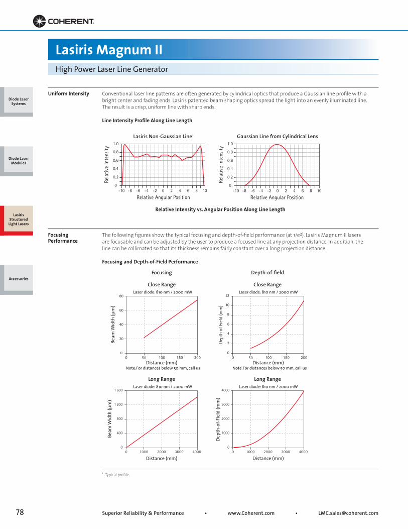
Superior Reliability & Performance • www.Coherent.com • [email protected]
0 50 100 150 200
Beam
Wid
th (µ
m)
Distance (mm)
1 600
1 200
800
400
00 1000 2000 3000 4000
Beam
Wid
th (µ
m)
Distance (mm)
0
20
40
60
80
Dept
h of
Fie
ld (m
m)
Dep
th-o
f-Fie
ld (m
m)
0 1000 2000 3000 4000
Distance (mm)
4000
3000
2000
1000
0
12
10
8
6
4
2
00 50 100 150 200
Laser diode: 810 nm / 2000 mW
Laser diode: 810 nm / 2000 mW
Laser diode: 810 nm / 2000 mW
Laser diode: 810 nm / 2000 mW
Note: For distances below 50 mm, call usDistance (mm)
Note: For distances below 50 mm, call us
Lasiris Magnum IIHigh Power Laser Line Generator
Uniform Intensity
Focusing Performance
Conventional laser line patterns are often generated by cylindrical optics that produce a Gaussian line profile with abright center and fading ends. Lasiris patented beam shaping optics spread the light into an evenly illuminated line.The result is a crisp, uniform line with sharp ends.
Line Intensity Profile Along Line Length
The following figures show the typical focusing and depth-of-field performance (at 1/e2). Lasiris Magnum II lasersare focusable and can be adjusted by the user to produce a focused line at any projection distance. In addition, theline can be collimated so that its thickness remains fairly constant over a long projection distance.
Focusing and Depth-of-Field Performance
1 Typical profile.
1.0
0.8
0.6
0.4
0.2
0-10 -8 -6 -4 -2 0 2 4 6 8 10
Rela
tive
Inte
nsity
Relative Angular Position
1.0
0.8
0.6
0.4
0.2
0-10 -8 -6 -4 -2 0 2 4 6 8 10
Rela
tive
Inte
nsity
Relative Angular Position
Focusing
Long Range
Depth-of-field
Long Range
Lasiris Non-Gaussian Line1
Relative Intensity vs. Angular Position Along Line Length
Gaussian Line from Cylindrical Lens
Close Range Close Range
Diode Laser Systems
Diode Laser Modules
Lasiris Structured
Light Lasers
Accessories

• Toll Free: (800) 343-4912 • Tel: (408) 764-4042 • Fax: (503) 454-5727 79
Lasiris Magnum IIHigh Power Laser Line Generator
OpticalSpecifications
EnvironmentalSpecifications
ElectricalSpecifications
DB-9 Pinout and Back Panel Diagram
Wavelength (nm) 635, 665, 680, 808, 810, customOutput Power (mW) 500 to 7000Intensity Distribution Uniform (non-Gaussian) lengthwise, Gaussian widthwiseFan Angles1 (°) 10, 15, 20, 30, 40, 45, 55, 60, 75Line Thickness (focus) User adjustableNoise (%) <1 at ambient temperature (Max. RMS variation)Power Stability (%) <3 at ambient temperature (Max. variation in 24 hrs)Pointing Stability (μrad/°C) 10Bore Sighting (mrad) <3 (collimated)
Operating Temperature (°C) -35 to +50 for most modelsStorage Temperature (°C) -40 to 60Wavelength Drift Maximum ±1 nm over entire operating temperature range
Power Supply Voltage (VDC) 12 ±0.5 An adapter is available to supply the unit from 110/240 VAC linePower Supply Current (A) 3 to 5 depending on laser powerBuilt-In Protection Entire product: ESD, over-voltage up to 20V, reverse polarity of power supply. Laser diode: overheating, over-currentLaser Diode Operating Temperature (°C) 25 ±1 (adjusted in factory)Maximum Beam Power User adjustable (trim potentiometer on the back panel)Beam Modulation External, through a DB-9 connector on the back panelInput Impedance (kW) 1Monitoring Laser temperature, laser current, PD current through DB-9
Power Options Power Adjustment Potentiometer Laser power can be easily changed by adjusting an optional built-in potentiometer with a small screwdriver. Code “P”. Power Adjustment by External Signal Standard modulation S (synchro) or RS (reverse synchro): DC to 10 kHz S: Input voltage = 0VDC → laser “ON” RS: Input voltage = 5VDC → laser “ON”
T (TTL) or RT (Reverse TTL): DC to 10 kHz Transition 2 to 3 VDC T: Input voltage = 0VDC → laser “ON” RT: Input voltage = 5V → laser “ON”
“Fast” Modulation FS (fast synchro), FRS (fast reverse synchro) or FT (fast TTL0, FRT (fast reverse TTL) DC to 300 kHz
GND
Photodiode Current Monitor
Diode Current Monitor
SCL (future option)
Board Temperature Monitor
Internal Use
Modulation Input
SDA (future option)
Diode Temperature Monitor
Diode current (mA) diode current monitor (mV)Power (mW) photodiode current monitor (mV)
Pin 1
Pin 9
ReverseTTLModulation
Vmod (V)0 1 2 3 4 5
DirectTTLModulation
Optic
al Po
wer
Transitional states
ReverseLinearModulation
Vmod (V)0 1 2 3 4 5
DirectLinearModulation
Outp
ut Po
wer
Factory set values
Standard Option –S
Option –RS
Option –T
Option –RT
Counter (Hou s)
Modulat on & Mon to ing
PowerAd ustment
Max
Maintenance
Wa n ng12 VDC
Main Switch
Sa
fety In erlock
Timer LCD
Modulation andMonitoring DB 9
Power Supply Input12V (± 0.5V)
Base Plate
Remote SafetyInterlock
Key LockSwitch
MaintenanceYellow LED
ProtectionRed LED
Beam PowerAdjustment
Potentiometer
Green LED(Power ON)
ON/OFF (I/O)Power Switch
Diode Laser Systems
Diode Laser Modules
Lasiris Structured
Light Lasers
AccessoriesOptions

Superior Reliability & Performance www Cohe ent.com • [email protected]
1.7 51 60543.5640.77
SEE NOTE (A,B,C)
0 7500 74819.0519.00
CLAMPING SURFACE
COLDRAY LASER
B) ADD 3.480 0 020/ 0.020 [8 0 FLOW CY OMETRY FL
Ø
0.760
19.05
1Ø 9.05
CLAMPING SURFACE
SINGLE MODE FIBERLENGTH: 2M
3 5
0 4819 00
S RFAC
Lasiris Flat Top ProjectorGaussian to Flat Top Using Refractive Beam Shaping Optics
Side ViewMechanical Specifications
PureBeam/Fiber Option
Side View
Side ViewFront View
ColdRay Laser Option
Free Space Option
Diode Laser Systems
Diode Laser Modules
Lasiris Structured
Light Lasers
Accessories
0 7600.75019.3019 0
SEE NOTE (A,B,C)
0.7500.7481Ø 9 019.00
CLAMPING URFAC
FC/APC FIBER CONNECTOR
INGL MOD FIB RL NGTH 2M
BEAM / F
1 71 6043.5640 77
(A B,C)
0 7419.0519 00
S RFACE
C) ADD 0.890 +0 005/ 0.005 [2 0 OCUSED FLAT TOP
0.3040.2947.737.48
0.7500.74819.0519.00
SEE NOTE (A,B,C)
M14 x 0.5 THREADX 0.375 [9.50] DEEP.
n [mm]
Ø
• Toll Free: (800) 343-4912 • Tel: (408) 764-4042 • Fax: (503) 454-5727 81
Lasiris Flat Top ProjectorGaussian to Flat Top Using Refractive Beam Shaping Optics
Key Features
• Very efficient all glass optics
• Achromatic (from UV to near IR)
• Very smooth low ripple uniformity profile with no high frequency noise
• Uniformity coefficient of variation of better than 1% achievable
• High aspect ratios available off the shelf
• High uniformity edge steepness
Ordering Information
To order, use the following code: BSO-MODEL-Wavelength-POWER-Type-FT Size-WD (Note: Size in degrees for DFT; size in μm for FFT; size in mm for WD). E.g., BSO-FS-660-60-DFT-1x3 (Free Space for 660 nm 60 mW Diverging with a FT size of 1 x 3 degrees). E.g., BSO-CR-660-60-FFT-300x900-100 (ColdRay for 660 nm 60 mW Focusing with a FT size of 300 x 900 μm at 100 mm).
Input Type ColdRay Laser Option Coherent TEC direct semiconductor free space laser Order code: CR - Wavelength - Power E.g., CR-640-80) Free Space Option M14 threaded holder. Requires input beam dimension (IBD): 0.5 mm up to 4 mm Gaussian at 1/e2
Order code: FS-IBD (E.g., FS-4) Fiber Option FC/PC input end, 2 m shielded, NA: 0.12, FC/APC exit end. Requires operating wavelength between 405-830 nm Order code: FIB - Wavelength (E.g., FIB-640)
Flat Top Type One Dimensional Diverging Flat Top Order code: 1DDFT - Divergence (E.g., 1DDFT-0.3°) Two Dimensional Diverging Flat Top Order code: 2DDFT - Divergence 1 x Divergence 2 (E.g., 2DDFT-0.3°x2°) Imaged Flat Top Order code: FFT - Divergence 1 x Divergence 2 - Focal Length (E.g., FFT-0.3°x02° - F50)
Beam Splitter Type Order code: Number of beams - Period (E.g., 19B-50 μm)
Diode Laser Systems
Diode Laser Modules
Lasiris Structured
Light Lasers
Accessories
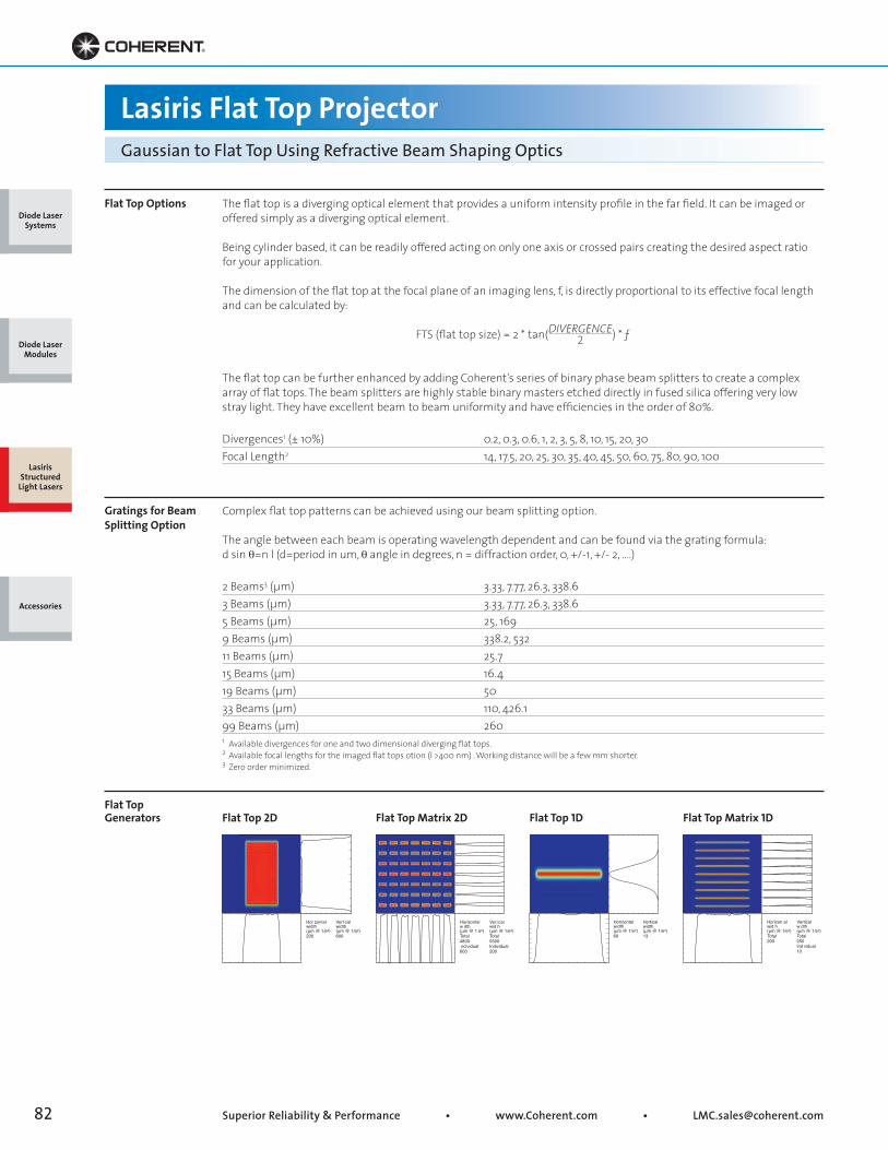
Superior Reliability & Performance • www.Coherent.com • [email protected]
Lasiris Flat Top ProjectorGaussian to Flat Top Using Refractive Beam Shaping Optics
Flat Top Options
Gratings for Beam Splitting Option
The flat top is a diverging optical element that provides a uniform intensity profile in the far field. It can be imaged oroffered simply as a diverging optical element.
Being cylinder based, it can be readily offered acting on only one axis or crossed pairs creating the desired aspect ratiofor your application.
The dimension of the flat top at the focal plane of an imaging lens, f, is directly proportional to its effective focal lengthand can be calculated by:
FTS (flat top size) = 2 * tan(DIVERGENCE) * ƒ
The flat top can be further enhanced by adding Coherent’s series of binary phase beam splitters to create a complexarray of flat tops. The beam splitters are highly stable binary masters etched directly in fused silica offering very lowstray light. They have excellent beam to beam uniformity and have efficiencies in the order of 80%.
Divergences1 (± 10%) 0.2, 0.3, 0.6, 1, 2, 3, 5, 8, 10, 15, 20, 30Focal Length2 14, 17.5, 20, 25, 30, 35, 40, 45, 50, 60, 75, 80, 90, 100
Complex flat top patterns can be achieved using our beam splitting option.
The angle between each beam is operating wavelength dependent and can be found via the grating formula:d sin θ=n l (d=period in um, θ angle in degrees, n = diffraction order, 0, +/-1, +/- 2, ....)
2 Beams3 (μm) 3.33, 7.77, 26.3, 338.63 Beams (μm) 3.33, 7.77, 26.3, 338.65 Beams (μm) 25, 1699 Beams (μm) 338.2, 53211 Beams (μm) 25.715 Beams (μm) 16.419 Beams (μm) 5033 Beams (μm) 110, 426.199 Beams (μm) 260
2
1 Available divergences for one and two dimensional diverging flat tops.2 Available focal lengths for the imaged flat tops otion (l >400 nm) . Working distance will be a few mm shorter.3 Zero order minimized.
Flat Top Generators Flat Top 2D Flat Top 1DFlat Top Matrix 2D Flat Top Matrix 1D
Horizontalwidth(μm @ 1/e2)60
Verticalwidth(μm @ 1/e2)13
Horizontalw dth(μm @ 1 e2)Total4800nd vidual
600
Ver icalwid h(μm @ 1/e2)Total5500Individual200
Horizon alwid h(μm @ 1/e2)Total200
Verticalw dth(μm @ 1/e2)Total250Ind vidual10
Hor zontalwidth(μm @ 1/e2)200
Vert calwidth(μm @ 1/e2)600
Diode Laser Systems
Diode Laser Modules
Lasiris Structured
Light Lasers
Accessories
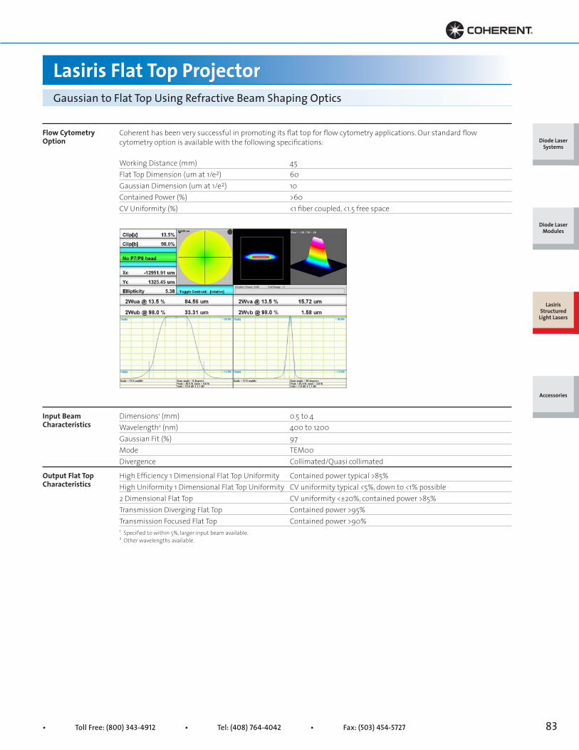
• Toll Free: (800) 343-4912 • Tel: (408) 764-4042 • Fax: (503) 454-5727 83
Lasiris Flat Top ProjectorGaussian to Flat Top Using Refractive Beam Shaping Optics
Flow Cytometry Option
Input Beam Characteristics
Output Flat Top Characteristics
Coherent has been very successful in promoting its flat top for flow cytometry applications. Our standard flowcytometry option is available with the following specifications:
Working Distance (mm) 45Flat Top Dimension (um at 1/e2) 60Gaussian Dimension (um at 1/e2) 10Contained Power (%) >60CV Uniformity (%) <1 fiber coupled, <1.5 free space
Dimensions1 (mm) 0.5 to 4Wavelength2 (nm) 400 to 1200Gaussian Fit (%) 97Mode TEM00Divergence Collimated/Quasi collimated
High Efficiency 1 Dimensional Flat Top Uniformity Contained power typical >85%High Uniformity 1 Dimensional Flat Top Uniformity CV uniformity typical <5%, down to <1% possible2 Dimensional Flat Top CV uniformity <±20%, contained power >85%Transmission Diverging Flat Top Contained power >95%Transmission Focused Flat Top Contained power >90%1 Specified to within 5%, larger input beam available.2 Other wavelengths available.
Diode Laser Systems
Diode Laser Modules
Lasiris Structured
Light Lasers
Accessories
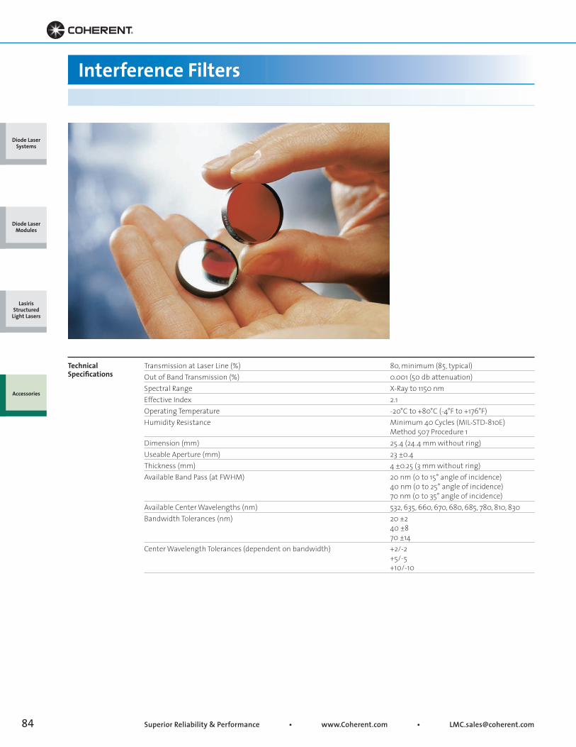
Superior Reliability & Performance • www.Coherent.com • [email protected]
Interference Filters
TechnicalSpecifications
Transmission at Laser Line (%) 80, minimum (85, typical)Out of Band Transmission (%) 0.001 (50 db attenuation)Spectral Range X-Ray to 1150 nmEffective Index 2.1Operating Temperature -20°C to +80°C (-4°F to +176°F)Humidity Resistance Minimum 40 Cycles (MIL-STD-810E) Method 507 Procedure 1Dimension (mm) 25.4 (24.4 mm without ring)Useable Aperture (mm) 23 ±0.4Thickness (mm) 4 ±0.25 (3 mm without ring)Available Band Pass (at FWHM) 20 nm (0 to 15° angle of incidence) 40 nm (0 to 25° angle of incidence) 70 nm (0 to 35° angle of incidence)Available Center Wavelengths (nm) 532, 635, 660, 670, 680, 685, 780, 810, 830Bandwidth Tolerances (nm) 20 ±2 40 ±8 70 ±14Center Wavelength Tolerances (dependent on bandwidth) +2/-2 +5/-5 +10/-10
Diode Laser Systems
Diode Laser Modules
Lasiris Structured
Light Lasers
Accessories

• Toll Free: (800) 343-4912 • Tel: (408) 764-4042 • Fax: (503) 454-5727 85
Interference Filters
Key Features
• 80% peak transmission
• Non-hydroscopic
• Wide bandwidth
Angle of Incidence and Blue Shifting
Laser Diode Tolerances
Ordering Information
The center wavelength of the filter will shift toward shorter (blue) wavelengths as the angle of incidence increases; the greater the angle the greater the shift (see % shift vs. angle of incidence graph). This is known as blue shifting. The amount of blue shift may be calculated using the following formula:
λ1 = λ0 (1 - sin2θ/n2)1/2
where θ = angle of incidence λ1 = resulting wavelength at angle q λ0 = central wavelength at normal incidence n = effective index of the filter
Another aspect to take into account when selecting a filter is laser diode tolerances. Diodes typically have a wavelength tolerance of ±10 nm; this wavelength (measured at room temperature) will increase with temperature increases and decrease with temperature decreases at a rate of 0.25 nm/°C.
To order a filter, choose the center wavelength and bandwidth from the Specifications on page 1. The order code is:<center wavelength> CW - <band pass> BP - 25.4-80%For example: 635CW-20BP-25.4-80%
Incidence Angle (degrees)
Filter WavelengthShift vs. Incidence Angle
Shift
in F
ilter
Wav
elen
gth
(%)
00
8.0
1.0
2.0
3.0
4.0
5.0
6.0
7.0
10 20 30 40 50
%
Diode Laser Systems
Diode Laser Modules
Lasiris Structured
Light Lasers
Accessories

Superior Reliability & Performance • www.Coherent.com • [email protected]
Diode LabLaser Universal Power Supply
31-1050-000 LabLaser Power Supply Power Supply, LabLaser, 6VDC, 250 mA, Adjustable Power Control for MVP1057734 Plug, 3.5 mm Stereo Phono Plug to take Laser Diode Module with leads and add a Power Supply Plug
Specifications
Key Features
• Fully-featured LabLaser 6 VDC power supply
• Variable laser power control
• Keylock, emission delay and remote interlock
The Diode LabLaser™ Universal Power Supply provides a well-regulated 6 VDC, 250 mA output for driving any of the Coherent Diode LabLasers with the additionalbenefit of variable power control. To vary the outputpower of the Diode LabLasers which incorporate theVariable Power and Modulation Control circuitry simplyadjust the multi-turn knob on the front panel of the31-1050 power supply. This varies a voltage on the “thirdwire” connection in the laser cables and the laserpower can be smoothly varied between threshold andthe rated power. The supply incorporates CDRH safetyfeatures (keylock, power-on indicator, 4-6 second
emission time delay and remote interlock socket), isCE-marked and meets appropriate UL, CSA, and ENrequirements.
This compact (120 x 76 x 48 mm) power supply canbe connected to any 90-130 or 180-260 VAC 50/60 Hzsupply. There is an IEC 320 input socket and a 1.8 mdetachable line cord with plug provided. The outputto the laser features an easy connect/disconnect3-terminal jack socket on the front panel which matesto the male plugs of the cables connected to allDiode LabLasers.
Diode Laser Systems
Diode Laser Modules
Lasiris Structured
Light Lasers
Accessories
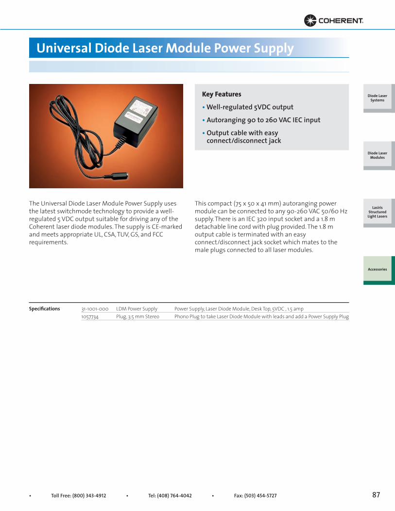
• Toll Free: (800) 343-4912 • Tel: (408) 764-4042 • Fax: (503) 454-5727 87
Universal Diode Laser Module Power Supply
31-1001-000 LDM Power Supply Power Supply, Laser Diode Module, Desk Top, 5VDC , 1.5 amp1057734 Plug, 3.5 mm Stereo Phono Plug to take Laser Diode Module with leads and add a Power Supply Plug
Specifications
Key Features
• Well-regulated 5VDC output
• Autoranging 90 to 260 VAC IEC input
• Output cable with easy connect/disconnect jack
The Universal Diode Laser Module Power Supply usesthe latest switchmode technology to provide a well-regulated 5 VDC output suitable for driving any of theCoherent laser diode modules. The supply is CE-markedand meets appropriate UL, CSA, TUV, GS, and FCCrequirements.
This compact (75 x 50 x 41 mm) autoranging powermodule can be connected to any 90-260 VAC 50/60 Hzsupply. There is an IEC 320 input socket and a 1.8 mdetachable line cord with plug provided. The 1.8 moutput cable is terminated with an easyconnect/disconnect jack socket which mates to themale plugs connected to all laser modules.
Diode Laser Systems
Diode Laser Modules
Lasiris Structured
Light Lasers
Accessories

Superior Reliability & Performance • www.Coherent.com • [email protected]
Variable Angle Diode Laser Mounts
0221-437-00 Mount for VLM2, FVLM2 or LG2 Variable Angle, 1/4-20 inch Base, 14.8 mm Bore0221-448-00 Mount for VLM3 or LG3 Variable Angle, 1/4-20 inch Base, 9.5 mm Bore0221-449-00 Mount, LabLaser/Industrial Variable Angle, 1/4-20 inch Base, 19 mm Bore
Specifications
Key Features
• Patent pending
• Simple tip/tilt and lock in place mechanism
• Very affordable
• Adjustable angle through about ±15 degrees
Coherent’s variable angle laser diode module mountsare designed to accept three different sizes of diodelaser module namely VLM3,VLM2 and LabLasers (9.5mm, 14.8 mm and 19.0 mm diameter).
This simple mount acts as combined heat sink,electrical insulator and variable-angle mount for 9.5or 14.8 mm diameter diode modules and 19.0 mmDiode LabLasers. The lasers are held firmly in aspherical-surface brass ring by two small set screws.This ring is clamped between two insulating blocksforming a “ball and socket” arrangement. Two socket-head screws can be loosened to allow easy angularadjustment of the module (±15° range) and quick, rigid locking in position.
(1) 1/4-20 Tapped Hole and(2) 8-32 Tapped Holes,9.7 mm (0.38 in.) Spacing
9.5/14.8/19.0(0.38/0.58/0.75 in.)Bore
12.7 mm(0.5 in.)
38.1 mm(1.5 in.)
44.5 mm(1.75 in.)
25 mm(0.98 in.)
Diode Laser Systems
Diode Laser Modules
Lasiris Structured
Light Lasers
Accessories
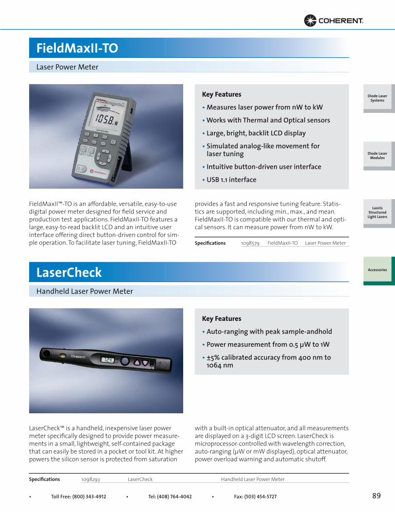
• Toll Free: (800) 343-4912 • Tel: (408) 764-4042 • Fax: (503) 454-5727 89
FieldMaxII™-TO is an affordable, versatile, easy-to-use digital power meter designed for field service and production test applications. FieldMaxII-TO features a large, easy-to-read backlit LCD and an intuitive user interface offering direct button-driven control for sim-ple operation. To facilitate laser tuning, FieldMaxII-TO
provides a fast and responsive tuning feature. Statis-tics are supported, including min., max., and mean. FieldMaxII-TO is compatible with our thermal and opti-cal sensors. It can measure power from nW to kW.
1098579 FieldMaxII-TO Laser Power MeterSpecifications
Key Features
• Measures laser power from nW to kW
• Works with Thermal and Optical sensors
• Large, bright, backlit LCD display
• Simulated analog-like movement for laser tuning
• Intuitive button-driven user interface
• USB 1.1 interface
Key Features
• Auto-ranging with peak sample-andhold
• Power measurement from 0.5 μW to 1W
• ±5% calibrated accuracy from 400 nm to 1064 nm
LaserCheck™ is a handheld, inexpensive laser power meter specifically designed to provide power measure-ments in a small, lightweight, self-contained package that can easily be stored in a pocket or tool kit. At higher powers the silicon sensor is protected from saturation
1098293 LaserCheck Handheld Laser Power MeterSpecifications
with a built-in optical attenuator, and all measurements are displayed on a 3-digit LCD screen. LaserCheck is microprocessor-controlled with wavelength correction, auto-ranging (μW or mW displayed), optical attenuator, power overload warning and automatic shutoff.
FieldMaxII-TO
LaserCheck
Laser Power Meter
Handheld Laser Power Meter
Diode Laser Systems
Diode Laser Modules
Lasiris Structured
Light Lasers
Accessories

Superior Reliability & Performance • www.Coherent.com • [email protected]
Key Features
• Thermally stabilized designs
• Broadband 0.3 to 11 μm spectral range
• High resolution to 10 μW
• Large area: 10 and 19 mm diameter
• Fiber-optic connector options
The PS model sensors offer a thermally stabilized,amplified power sensor with a broad spectral response,high sensitivity, and large active area. These sensors areideal for laser diodes, diode bars and stacks, HeNe,
HeCd and small ion lasers. For optimum performance at low power levels we recommend the PS10Q and PS19Q, which utilize quartz windows. PS10 models include a detachable beam tube to block stray light.
High-Sensitivity Thermopile SensorsTo 1W
PS10 PS10Q PS19 PS19QWavelength Range (μm) 0.3 to 11 0.3 to 2 0.3 to 11 0.3 to 2Power Range 100 μW to 1W 100 μW to 1W 100 μW to 1W 100 μW to 1WResolution (μW) 10 10 10 10Max. Thermal Drift 40 μW 20 μW 400 μW 20 μWMax. Avg. Power Density (kW/cm2) 0.5 0.5 0.5 0.5Max. Pulse Energy Density (mJ/cm2, 10 ns pulse) 50 50 50 50Response Time (sec.) 2 2 2 2Detector Coating Black Black Black BlackQuartz Filter Window - Yes - YesDetector Diameter (mm) 10 10 19 19Dimensions (mm) Φ 84 x 49 Φ 84 x 49 Φ 84 x 49 Φ 84 x 49Calibration Uncertainty ±1% ±1% ±1% ±1%Calibration Wavelength (nm) 514 514 514 514Cooling Method Air Air Air AirConnector Type PM DB-25 PM DB-25 PM DB-25 PM DB-25Cable Length (m) 2 2 2 2Part Number 1098350 1098400 1098413 1098341
SystemSpecifications
49 mm(1.93 in.)
Ø10 mm(0.39 in.)
84 mm(3.31 in.)
Adjustable184-254 mm
(7.24-10.0 in.)
49 mm(1.93 in.)
Ø19 mm(0.75 in.)
84 mm(3.31 in.)
Adjustable184-254 mm
(7.24-10.0 in.)
PS10/PS10Q PS19/PS19Q
Diode Laser Systems
Diode Laser Modules
Lasiris Structured
Light Lasers
Accessories

Visit the Coherent Websitefor more information about how Coherent can
enable your ultrafast laser application.
Use the Product and Application Finders belowto quickly get more helpful details.
Extensive Laser Finder
Powerful Diode Module Finder
Comprehensive Meter and Sensor Finder
Enhanced Application Finder
Brochures, Tech Notes, Technical Illustrations, Videos, Data Sheets
www.Coherent.com
• Toll Free: (800) 527-3786 • Tel: (408) 764-4983 • Fax: (800) 362-1170
Printed in the U.S.A. MC-004-11-2.5C1010Copyright © 2010 Coherent, Inc.
Coherent, Inc., Corporate Headquarters5100 Patrick Henry DriveSanta Clara, CA 95054
United States Coherent, Inc., Portland27650 SW 95th AvenueWilsonville, OR 97070United StatesToll Free: 1-800-343-4912Tel: (408) 764-4042Fax: (503) 454-5727www.Coherent.com
ChinaCoherent, Inc., BeijingRoom 215 Yin Gu BuildingNo. 9 Beisihuan Xi RoadHaidian DistrictBeijing, 100080, ChinaTel: +86-10-6280-0209Fax: +86-10-6280-0129www.Coherent.com.cn
FranceCoherent FranceDomaine Technologique de SaclayBâtiment Azur4, Rue René Razel91892 Orsay CedexFranceTel: +33-1-69-85-51-45Fax: +33-1-60-19-40-00www.Coherent.fr
GermanyCoherent GmbHDieselstraße 5bD-64807 DieburgGermanyTel: +49-6071-968-333Fax: +49-6071-968-499www.Coherent.de
ItalyCoherent ItaliaVia Borgese, 14Milano, 20154ItalyTel: +39-02-34-530-214Fax: +39-02-34-934-165www.Coherent.it
JapanCoherent Japan, Inc. Toyo MK Building7-2-14 ToyoKoto-ku, Tokyo 135-0016JapanTel: +81 3-5635-8680Fax: +81 3-5635-8701www.Coherent.co.jp
KoreaCoherent KoreaNo. 101, Eagle Town278-20, 3 dongSeongsu 2 gaSeongdong-gu, Seoul133-832, South KoreaTel: +82 2 460 7900www.Coherent.com
NetherlandsCoherent B.V.Smart Business Park Kanaalweg 18A3526 KL UtrechtNetherlandsTel: +31-30-280-6060Fax: +31-30-280-6077www.Coherent.nl
United KingdomCoherent UK Ltd.St Thomas’ PlaceCambridgeshire Business ParkElyCB7 4EXUnited KingdomTel: +44-1353-658-833Fax: +44-1353-659-110www.Coherent.com