Embed Size (px)
Citation preview
q ln l: l
: :
i :
6 9z .
; e
i i: u9 5
: 3
..i :
a:
E : i
U oc 621 . 873 -25 I 521 824 | 629 11 .012 351| 629 .11 . 012 .354 DEUTSCHE NO Rt "4 iu iy i : r9?
Krane; Tre ib - und Mi t lau fsd tze ; Zusammenste l lung
ln keeping with currcnt practice in standards published by the lntenational organizatibn for standardization'(lso)
a comma has been used throughout as the decimal marker'
D lmens ions in mm
1 F ie ld o f app l i ca t ion and scoPe
The spec i { i ca t ions conta ined in th is s tandard app ly to heavY dutY dr iv ing whee l unr ts
a n d i d l e r w h e e | U n i t s ' w h i c h a r e m o u n t e d m a i n l y i n c r a n e s . f o r m a n u f a c t u r i n g p | a n t s 'e .q . s tee lworks c ranes and ro l l ing rn i l l c ranes .
Th is s tandard is in tended to p rov lde ihe necessary base fo r s tandard iz inq dr v ing whee l
un i ts and id le r whee l un i ts , therebv s imp l i fY ing the l r in te rchangeab i l i t y and s to rage
Con t l nued on pages 2 t o 5
8 € ! r h v € r a g C n b t s . 8 e i l , n . l O . n a s e r c ! s r v e s a e ' r e h l s 1 o ' G e r m a n S l a n d a f d s ( D L N N o r m e n )
0 7 a 4
Dl^1 15 09A Engl Price grouP 5S a 6 s N o 0 r 0 5
D I N15 090Driving wheel
Cranesunits and idler wheel units
AssemblY
\
t s c 2 D l ' . 1 1 5 0 9 0
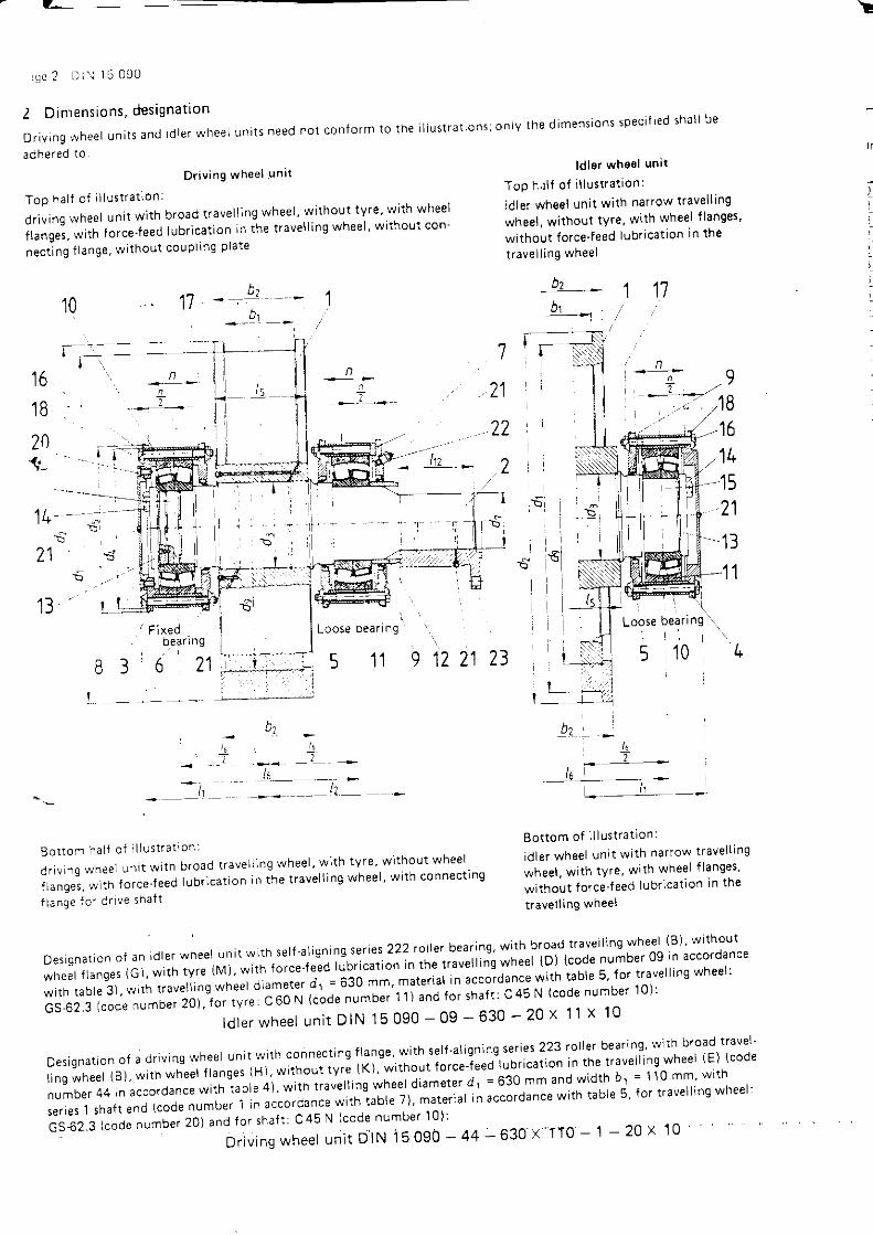
2 D imens ions ,des igna t i on
or iv ing whee l un i ts and rd te r wheer un i ts need no t con form to the i l l us t ra t ions ;on ly the d imens ions spec i f ied sha l l be
adhered lo
Dr iv ing whse l ln i t ld le r whee l un i t
Top ha l f o f i l l us t ra t ion : Top h r l f o f i l l us t ra t ion l
d r iv ing whee l un i t w i th b road t rave l l ing whee l ' w i thout tv re ' w i th whee l id le r whee l un i t w i th nar row t rave l l ing
f langes , w i th fo rce ' teed lubr rca t ron in ihe t rave l l ing whee l ' w i thout con- whee l ' w i thout ty re ' w i th whee l f langes '
necrins f ranse, without couprins prate l:tlfilJ1i:li" lubrication in the
1017
lo
I t,* -
Bot tom o f i l l us t ra t ion :
id le r whee l un i t w i th nar row t rave l l ing
whee l , w i th tYre , w i th whee l f langes '
w i thout fo rce- feed lubr ica t ion In the
t rave l l ing whee l
t o
1 B
7
21
22
2
t 7
20I
l +
21
1 3l F i x e d
0ear Inga 1
J 0 L l
\Loose bear ing
..\
L , !, _
{o- l t
Bo t to . f ha l t oJ i l l u s t ra t i on l
i , , . ^ ^ ^ nA ' t n r t w r tn b road r rave , r ' ng whee l , w ; t h IY ' e w r thou t whee l
; " ; ; " : ; , ; ; f o r ce t eed l ub r i ca r ron i n t he t r ave l l i ns whee l ' w i t h connec t rng
f l ange f o r d r i ve sha f t
D e s i q n a t i o n o f a n i d I e r w h e e l U n i t w i t h s e | { . a l i g n i n g s e r i e s 2 2 2 | o | | e | b e a t i n o - w i t h b r o a d t r a ! e | | i n g w h e e | ( B ) , w i t h o u rwneet f langes (G) , w i th ty re iu t , wr in to rce- teea lubr ica t ion in t t , " t r .u t t i in i * i ' ee l (D) (code number 09 in accordance
wi th rab le 3 ) , w i th t rave l l ing wn* i ' " t " i t ' J t -= e3O mm'mater ia l - in t " to iaun"u * i t t ' tab le 5 ' Io r t rave l l ing whee l :
GS,62.3 (code number 20) , lo r t r t ' ; ; ; ; 'N lcode number 11) and fo r sha f t : C 45 N (code number 10) :
l d l e r whee l un i t D IN 15 O9O - Og - 630 - 20 X 11 X 10
D e s i q n a t i o n o f a d r i v i n g w h e e l u n I r w i t h c o n n e c t i n g f l a n g e , W i t h s e l f . a | i g n i n q s e r i e s 2 2 3 r o | | e r b e a r i n g , w i t h b r o a d t r a v e l '[;, y"i".i i,r -*,:';: tlr:lyii]j,]li:W 1;mjn:*n;i*:;r,lm::i"Ji:!T.:":ilJffi:fln''""l"".[:T,fli,';ji::il"l,Lil,lTliillJll'il;ilil;');;;;'rln '""o'oun"' *ith tabre 5' ror traverrins wheer:
; t ; ; . . i ; ; ; ; " ; ;ou. zot uno ror shar t : c45 N (code number 10) :
- D r i v i n g w h e e l u n i t D I N i 5 O 9 o - 4 4 - 6 3 0 x T T O - ' , l - 2 0 x 1 0
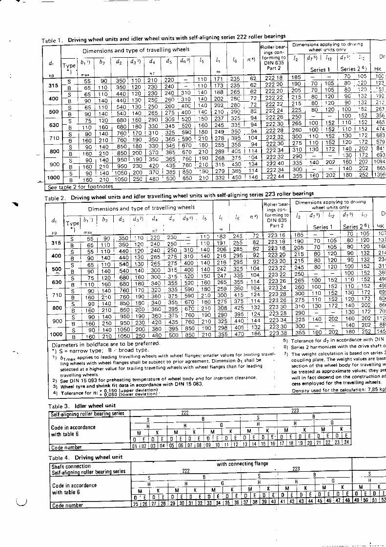
Driving wheel units and idler wheel units with self 'aligning series 222 roller bearrngsDimensiohs aPPlYing to d.Lvr .g
whoel ur i ts onlYDimensions and type of travell ing $'/heelsa 7 " ) . i
se es I -
265 275 400 140
1 1 0 1 5 2
4 0 5 1 1 43 7 0 3 8 5 6 7 0 2 1 03 7 5 1 0 4
420 435 760 214370 385480 500 850 210
Table 2. Driving wheel units and idler travell ins wheel uni$ with sett ':
\
' ) S = narrowtype; B = broad tYPe.1) b1-", ucOt'". ,o leadrng travel lrng wheels with wheel f tanges: smaller values for leadinq travel '
r i , l i i ieer, w'trt *rteer f lanqes shal l be subiecl !o prior agreement Dimonsion bl shal l be
,el lctea ut a higher value for trai l ing travel l ing wheel! with wheel f lang€s than for leadrng
Diamerers in boldface are to be preferred
Se€ DIN 15 093 for p.eheal ing temp€rature ot-wheel .bodv^3nd for insert ion c learance
i l iJi,". "io .r '.r"r f it deta in sccordancs with olN 15 083
ror"-n"" r- n, : 3:3:3 lii,g:i 5:JfiiSli
6 )
7 l
Tolerance for d7 in accordance wi th OIN
sor i€s 2 harmonizes vYi th the dr i r " l shal t c(
The werqht calculat ion is b6s€d on ser ies l
coupl ing plate- The w€ight values are base
sect ion ol the wh€€l body for t ravol l ing " tb€ t reated as approximate values; they ar t
wi l t in fact d€p€nd on th6 conslrucl ion ad
cts3 eanployed for tht tr6v€llin9 whe€l!
for the calc\ i la t ion: 7
Dirnensions aPPlVing to drrvrngwheel unrts onlVings con-
DtN 635Pa^ 2
D imens ions and t ype o f t r ave l l i ng whee l s
A , a , d r d " d ' d q ' r I d j " ) 1 1 2l : t dt ') In
1 8 3 2 4 5go :so ro 22A 230 - 110
265 275 400 I 1401 4 0 3 0 0 3 1 5
3 0 0 3 1 5 5 2 0 r 1
1 1 0 1 5 2
3 7 5 1 1 4
5 124375 760 190
l . l
Cods in accordancewittr bble 6
Code in accordancewith t ble 6
,J
r
DIN 15 090 Paqe 3
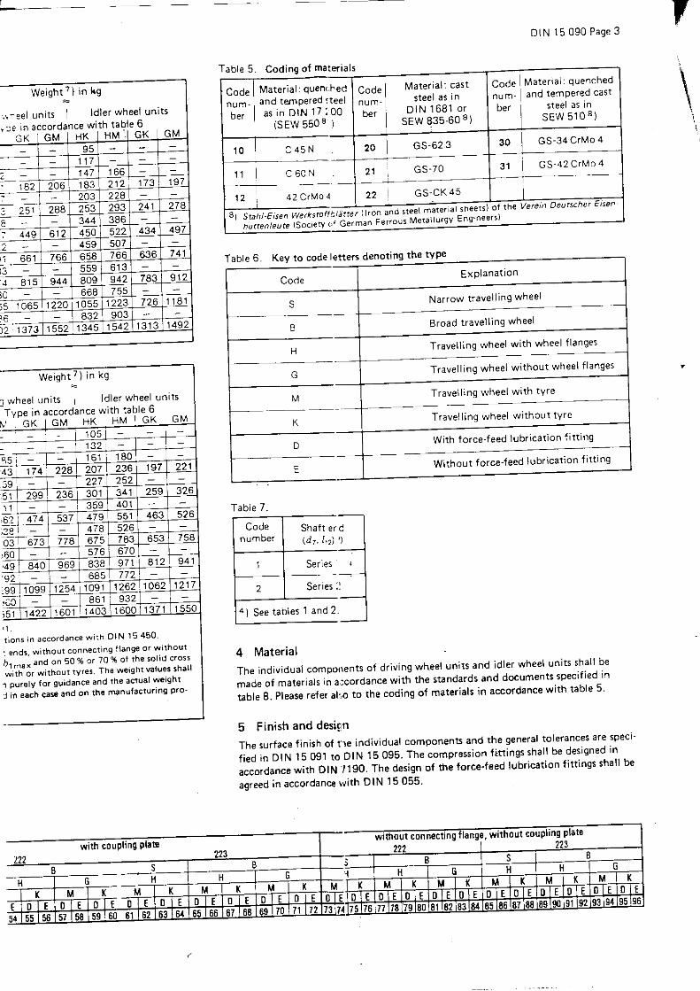
Table 6. Kev to code lette6 denoting the type
4 Material
The individual components of driving wheel units and idler wheel-unitsrhall be
r"i" ot t"t"ria, in a:cordance witl i t ie standards and documents specified rn
table 8. Please relef alrc to the codtng o{ materials in accordance with table 5'
5 F inish and desiqn
The5Ur face f in isho f t le ind iv idua |componentsandthegenera I to ]e rancesarespec i .i,"j i" o rru 1 5 09.1 ro D tN 15 095. The compression fitt ings shatl be.desisned in
accordance with DIN /190. The design of the force'feed lubrication fitt ings shall b€
agreed in accordanc€ tvith DlN I5055'
codrng o{ materials
Code Ma te r i a l : quenched
nu m. and iemPered casr
ber steel aS !ns E W 5 1 0 8 )
Mate r i a l : cas is tee l as i n
D I N 1 6 8 1 o rsEW 835'60 8)
c^.ra I Material quen( hed
"ra-- | ana ternPered:teel
i . . I a s i n D I N 1 7 : 0 0- - I ( s E W 5 5 0 8 I
30 I GS-34 c rMo 4
1 1 c 6 0 N
12 42 c rN ' l o 4
3 1 G S - 4 2 C r M o 421 GS-70
22 GS 'CK 45
Weight 7 ) in kg
, . , ^ee l un i ts I ld le r whee l un i ts
, re rn accordance w i rh Iab le -6 . .G K I G M I H K L H M ' I 9 K I \
951 1 7147 1 6 6
. 1 8 2 206 1 8 3 212 173 1 9 7
243 224288 293 241 278
344 386449 6 1 2 450 434 497
459 507l1 658 766 636 7 4 1
559{ 8 1 5 944 809 942 9 1 2
668l l 1223 726 1 8 1
903' r , 1373 1 5 5 21 3 4 5 1542 1 3 1 31492
ExPlanat ion
Nar row t rave l l ing whee l
Eroad t rave l l ing whee l
Trave l l ing whee l w i th whee l f langes
Code
s
B
G Trave l l ing whee l w i thout whee l t langes
Trave l l ing whee l wr th tYre
Trave l l ing whee l w i thout tYre
With force-f eed lubrication {itt ing
Without f orce-feed lubrication f i l t ing
M
?
Weigh tT ) i n kg
r whee l un i t s l d l e r whee l un
Tvoe in accordance with table-6-L t . : K I G M H K H M 1 G K 1 M
1 0 51321 6 1 1 8 0
4 : 1 7 4 207 236 1 9 7 221227 252
5 1 299 236 301 341 259 326359 401
,62 474 479 551 463474 526
774 783670
,49 840 969 9 7 1 9 4 1772
:99 1099 1 2 5 4 1 0 9 1 1262 1062 1217
8 6 1 9321422 1 6 0 1 1403 1600 1 3 7 1 1 5 5 0
r i o n s i n a c c o r d a n c e w i t h O I N 1 5 4 5 0
I ends- \^r thour connecrrag f lange or wrthot ' l I
h- and on 50 % :r 70 % of the sol 'd cross
"J ' i i i , , , r i , r ,out ,v ' " t The wersht values shar l
l ourelv for guidan@ and the acrual wergnr
I in each case and on the rY€nufactur ing pro '
Tab le 7 .
Shaft er d( d r . I , z ) ' )
4) See tab les 1 and 2 .
L
P a g e 4 D I N 1 5 0 9 0
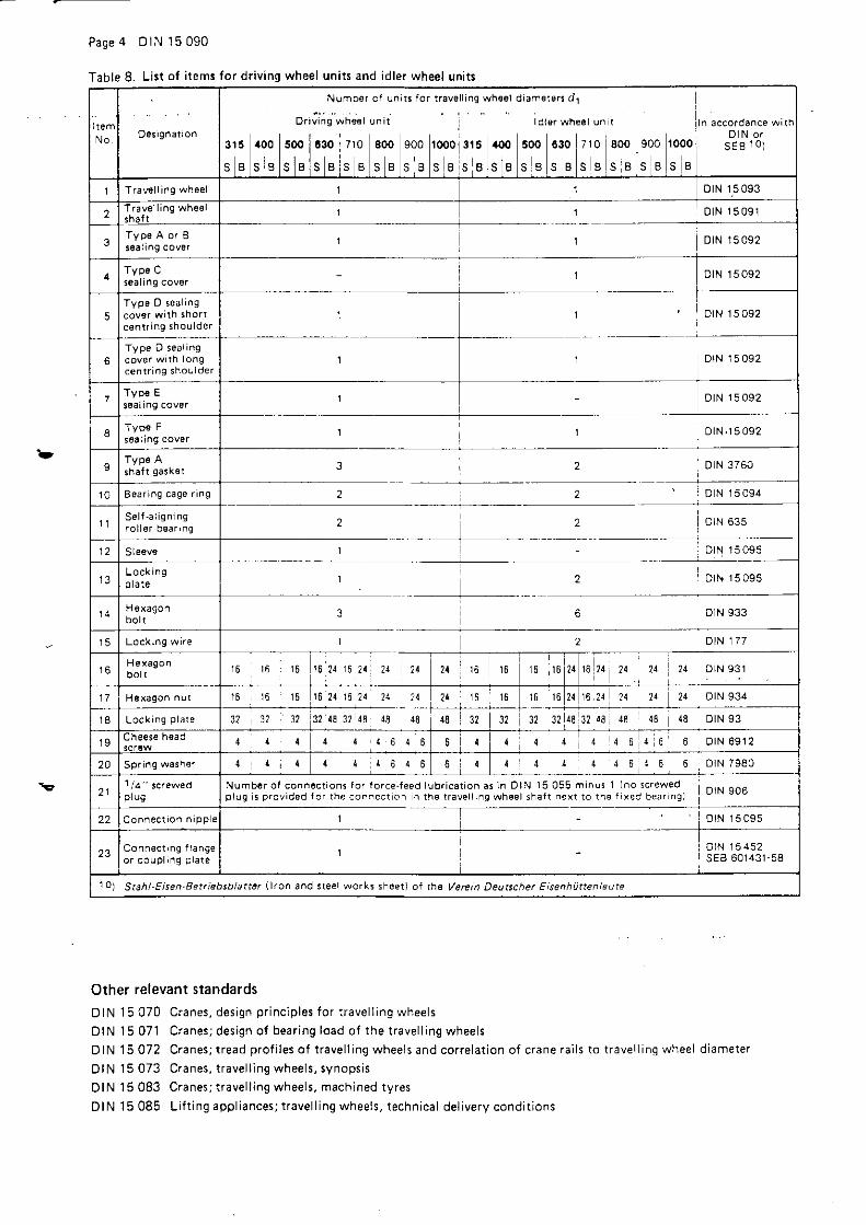
Table 8. Lirt of items for driving wheel units and idler wheel units
Other relevant standardsDIN 15 070 Cranes , des ign pr inc ip les fo r i rave l l ing whee ls
DIN 15 071 Cranes ; des ign o f bear ing load o f the t rave l l ing whee ls
D I N ' 1 5 0 7 2 C r a n e s ; t r e a d p r o f i l e s o f t r a v e l l i n g w h e e l s a n d c o r r e l a t i o n o f c r a n e r a i l s t o t r a v e l l i n q w h e e l d i a m e t e r
DIN 15 073 Cranes , t rave l l ing whee ls , synops is
DIN 15 083 Cranes ; t rave l l ing whee ls , mach ined ty res
D1N15085 L i f t ing app l iances ; t rave l l ing whee ls , techn ica l de l i very cond i t ions
D e s i g n a t i o n
Numb€r of uni ts for t rave
oriJiris wr,ier ,rnit l
315 a00 500 1c30 7r0 800 900 r@0^ ^ ^ ^ ^ l - l ^ ^ . ^ - ^5 E 5 n J E J E s O ) E 5 t J U
l ing wh€ol diam€r€rs d1
ialer wtreet un t
3r5 aoo 500 030 710 800 900 1000
s 8 s 8 s I s 8 s I s B S B S B
n accordance wrtnD l N o r
s E B I o )
Tra!€ l ing whoel l orN 15093
2 T r a v e l l i n g w h e e l 1 D t N 1 5 0 9 1
3Typ6 A or Is ta l rn9 cov0r 1 DtN 15 092
soal tn9 cov€r0 tN 15 092
5Typo D seal ing
cenrr ing shoulder1 DtN 15 092
6Type D seal ing
c e n t r i n g s h o u l d e rl D I N 1 5 0 9 2
7Typ€ Eseatrng cover 1 o tN 15 092
soal ing cover1 o tN . r 5 092
I shal t gasket 3 2 olN 3760
1 0 Bear ing cage r ing 2 2 o N 1 5 0 9 4
I ]S e l f - a l i g n i n gr o l l 6 r o e a n n g 2 2 D IN 635
12 Sle6ve 1 - D rN 15 095
1 3L o c k i n gp l a r e 1 2 DrN 15 095
H€xagon 3 6 D IN 933
Lockin9 wire l 2 D t N 1 7 7
H e x a g o n1 6 1 6 1 6 16 24 16 21 2,r 21 2a 16 16 t6 16 21 16 24 24
.. ?4 21 D I N 9 3 1
1 7 t6 r6 r6 1 6 2 1 1 6 2 4 2 1 2 4 24 16 l 6 t 6 16 24 16 24 24 21 21 o tN 934
t 8 L o c k i n g p l a t e 3? 37 32 32 18 32 18 48 48 48 32 32 48 32 48 48 { 8 18 DrN 93
1 9 cheese h6ad 4 4 4 4 6 4 6 6 4 4 4 4 4 6 6 o r N 6 9 1 2
20 Spring waih€r 1 6 4 6 6 I 4 1 6 6 D r N 7 9 8 0
21 p lusNumb€r ol connecr ions for forceJeed lvbr icat ion as in DlN lS 055 minus l (no scre! 'vedp l ! q i s p r o v i d e d f o r t h e c o n n e c r o n n r h e t r a v e l l r n g w h e e l s h a f t n e x t 1 o t h e f i x e d b e a r n g ) DIN 906
22 C o n n e c l i o n n i p p e I DtN r 5 095
23 C o n n e c t i n g f l a n g eo r c o u p r n g p r a t e
IDtN I 5 452sEB 601431 '58
1o) Stahl-Eisen.Bet iebsbl . i t ter lkon a^d t teel works sh€et) of rh€ Varein Deutschet Etsenhiatenleute
DIN 15 090 Page 5
StandarCs 'a '=-?= ' -a : - c other documents
D I N ; : - : : : : : - : ' i
" ' : ' 1 r o n g t a b
DIN l : : = 'z ; , ' s iee l w i re ;d i rnens ions ' permiss ib le dev ia t ions ' we lgh ts
D l \ : i i : : - - i : : - : : - 1 . ! ' o l e r j o u r n a l b e a r i n g s a n d s e l f ' a l i g n i n g r o l l e r ( i o u r n a l ) b e a r i n g s
D ' . - . : - : ' : : : - l J c r e t P i g e P l u g s
: ' . : - - : ' : : : - -ead screws w i th met r ic th read, des igns m and mg
: ' , : : - - . , : : . . - e a d s c r e w s ; t h r e a d a p p r o x i m a t e l y t o h e a d ' M 1 ' 6 t o M 5 2 m e t r i c t h r e a d s ; p r o d u c t g r a d e s A
: - : 3 -od i f ied vers ion o f ISO 4017)
: . : - : - : ra -con nu ts w i th met r ic th read;produc t g rades A and B
: , - . ' S : .e cas t ings fo r genera l use ; qua l i t y spec i t i ca t ions
: ' . : - : : a3d ia sha{ t gaskets
- - . : : ' : r - iexaqon socket cheese head screws; sha l low head w i th p i lo t recess fo r wrench key
I . - ' ? - - Ces ign and app l ica t ion o f compress ion f i t t ings
: , - ; : : Spr ing washers fo r cheese head screws
: ' . : :aa Equ ipment and c ranes fo r s tee l works and ro l l ing mi l l s ; lo rce- feed lubr ica t ion methods ' app l i ca t ion '
d r rnens lons , des ign gu ide l ines
: , ' : :83 Cranes ; t rave l l ing whee ls , mach ined ty res
: ' , ' : l9 i Cranes ;dr iv ing whee l un i ts and id le r whee l un i ts ' t rave l l ing whee l sha f ts
a ' . ' a a32 Cranes ; d r iv ing whee l un i ts and id le r whee l un i ts ' sea l ing covers
I ' , 3 193 Cranes ;dr iv ing whee l un i ts and id le r whee l un i i s ' t rave l l ing whee ls
- : ' , ' 5 l9 , l Cranes ; d r iv ing whee l un i ts and id le r whee l un i ts ' bear ing cage r ings
: . , .5 C-os c ranes ; d r iv ing whee| un i ts and id |e r Whee l un i ts , Iock ing p |a tes , s leeves , n |pp |es
^ ' . ' 5 J5O Cranes;des ign o f d r ive shaf ts fo r the dr iv ing o f t rave l l lng whee l un i ts
: ' , i5 ,152 Cranes ; connect ing f langes fo r d r ive shaf ts
I ' . 17 2OO Ouenched and tempered s tee ls , qua l i t y spec i f i ca i ions
S: : aO ' ,131 58 R igrd p la te coup l ings w i thoJr coug l ing guard
S: , ' , 510 Ouenched and tempered cas t s tee l fo r cas t ings w i th wa l l th icknesses up to 100 mm
SE, ' ; 550 Stee ls fo r la rge fo rg inE;qua l l t y spec i f i ca t ions
SE, ' i 835 '60 Cast s tee l fo r f lame harden ing and induc t ion harden lng
lnternational Patent Classification
I 66 C 9108

6
;
:
E6
:as
oz
E
-
_ r l
a l
i l
; l
MannesrnannDomag
HtitlontcchnikM c t a t l r e w l n n r r n ,
KraneTreib- und Mit laufsdtze
Laufradwel len
DIN15 091
Cranes ; d r i ven and ro ta t i ng ax les i sha f l s
Appa re i l s de l evage ; ess ieux command6s e t t ou rnan ts : a rb res
M aBe i n mm
1 Anwendungsbereich und ZweckAu f Lau f radwe l l en nach d iese r No r rn we rden Lau f rede r nach D IN j 5 093 au fgesch rump i t ,um T re ib - und M l t l au f sd t ze nach D IN 15OgO he rzus te l l en .
Fo r t se t zung Se r te 2 b i s 4
NormenausschuB Masch inenbau (NAM) im D IN Deu tsches l ns t i t u t f i j r No rmunq e .V .
Varvielfdhigung lr. DNA-Merkblof l 3, Zif f . l .
DK 621.873-25 : 621.824 : 629.11 .012.354 D E U T S C H E N O R M Jul i 1982
DIN 15091 Jul 1982 Preisgr. Sv e ( r . N r 0 0 0 5
O A
o F v e A a L r d € r \ o r e n d L r c n A e L r h v e r a O G m b F . B 6 r l r n l O
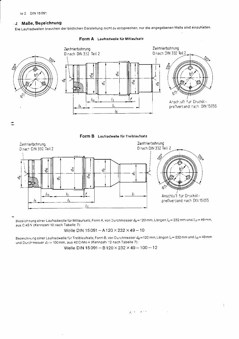
te 2 DIN 15 091
-2 MaBe, BezeichnungDie Lauf radwel len brauchen der b i ld l i chen Dars te l lung n ich t zu en tsprechen; nur d ie angegebenen MaBe s ind e inzuha l ten
Form A Laufradwelle f0r Miilaufsatz
ZentrierbohrungD nach DIN 332 TetL 2
AnschtuB fur Drucko[-pre l lvefban d nach 0 lN 15055
Fofm B Laufradwelle fi ir T.eiblautsatz
ZeniflerbohrungD r a c h D I N 3 3 2 I e t l 2
Zenlr ierbohrung0 nach DIN 332 TeiL 2
AnschluB fur Druckdt-preBverband nach DIN 15055
Beze i ch nung e ine r Lau f radwe l l e f i j r M i t l au f sa t z , Fo rm A , von D u rchmesse r d8 : 120 mm, Ldngen l a = 232 mm und 11o = 49 mm,
aus C 45 N (Kennzah i 10 nach Tabe l l e 7 ) i
wc l le D IN 15 091 - A 1 20 x 232 x 49 - 10
Beze i chnung e ine r Lau l radwe l l e f l i rT re ib l au f sa t z ' Fo rm B vonDurchmesse rdB=120 rnm 'Langen14=232mmund l1o=49mm
und Du rchmesse r d r = 100 mm, aus 42 C rN ' l o 4 (Kennzah l 12 nach Tabe l l e 7 ) :
W e l l e D I N 1 5 0 9 1 - B 1 2 0 x 2 3 2 x 4 9 - 1 0 0 - 1 2

Tabelle 1. Errechnete AbmaBe f i i r d3 nach ISO-Toleranzreihe 6 nach DIN 7151
1 1 0 120 130 1 4 0 1 6 0 1 7 0 1 8 0 1 9 0 200 230 2so
AbmaBe + 0,200+ 0 , 1 7 8
+ o ,220+ 0 , 1 9 8
+ 0,230+ 0,205
+ 0.250 + 0 ,280 + 0,300 + 0 ,310+ 0 ,285
+ 0.330+ 0 ,301
+ 0 ,350+ 0 ,321
+ 0.390+ 0 ,361
+ 0,430+ 0,401
Tabelle 2. Toleranz f i i r d, nach DIN 7'160
brs1 1 0 riber 1'10 bis 140 i i be r 140
fobGnz m6 n 6 p6
Tabelle 3. Errechnete AbmaBe fi ir d7 nach tso-Toleranzreihe 6 nach OtN 7.151
70 80 90 1 0 0 1 1 0 120 1 3 0 1 4 0 1 8 0
AbmaBe + 0 , 1 5 5 I + 0 , 1 6 5+ 0 , 1 3 6 + 0 . 1 4 6
+ O, l BS I + 0 ,210+ 0 ,163 + 0 ,188
+ 0 ,235+ 0 , 2 1 3
+0.250+ 0 ,228
+ o ,27 5+ 0,250
+ 0,290 + ! . J . r / c+ 0,305 + 0,350
Tabelle 5. Laufradwellen t i i r Tfeib- und Mif laufsatze mit pendelrol lenlagern der Reihe 222Lau f .ad
ou'T,T;tt"' to',.n ', d : 3 ) de ") d t o
h 9d t z d t z
nur fi i r Tredr') I7
Re ihe 1
b la ! f sa t zed rs ) L jRe ihe 2 6 )
I3 l4 18 l9 l t o
3 t 5 s 1 1 0 9 0 1 0 5 1 1 7 6 0 M 1 6 70 142 107 1 9 5 38120 1 0 0 1 2 7 70 M 1 6 70 142 80 1 1 7 107 1 8 9 277 44
400S 124 1 0 0 1 1 5 1 2 7 70 M 1 6 70 102 80 1 1 7 1 3 7 2 1 9 307 44
1 3 0 1 1 0 125 137 7 5 M20 80 1 1 7 90 129 137 227s
cvu - --; 130 1 1 0 125 75 M 2 A 80 1 1 7 90 l r o 227 329 51 46 ,5144 12A 1 3 5 147 85 M 2 0 80 1 1 7 ' 100 1 4 9 232 344 56 49
630 -+ 1 6 0 1 3 0 1 5 0 8 5 M 2 4 1 0 0 1 4 9 147 261 385 5 8 51 8 0 1 5 0 170 187 1 0 5 M24 1 0 0 1 4 9 1 1 0 1 4 9 157 262 404 7 1
7 1 0 IB
174 140 1 7 7 M 2 4 1 0 0 149 1 1 0 1 4 9 1 7 7 282 5t1 9 0 1 6 0 1 8 0 197 1 1 5 M 2 4 ' 1 1 0 1 4 9 130 1 6 9 207 3 1 5 4 7 1
800 !B
1 8 0 1 5 0 170 187 1 0 5 M 2 4 1 1 0 149 120 1 6 9 1 7 7 282 7 1 542AA 17A 190 210 125 M 2 4 1 3 0 1 6 9 140 1 9 9 247 3 1 9 447 84
900 s 1 9 0 1 6 0 1 8 0 197 1 1 5 M 2 4 1 3 0 187 451230 20a 220 240 145 N4 30 1 4 0 1 6 0 1 9 9 207 332 96 64
looo + 2AA 1 7 0 1 9 0 214 125 M 2 4 140 1 9 9 147 299 467 8425A 22A 240 260 1 6 5 M 3 0 1 6 0 1 9 9 1 8 0 249 2A7 342 106 69
s r e n e l a b e / t e 6
Tabelle 6. Laulradwellen l i i r Treib- und Mi aufsatze mit pendetrol lentagern de. Reihe 223Laufrad
D, r rchmesser - ^ .d . )
F o r m r ) de3 ) de ' ) d t o d I dn d nnur f r i r T r€
dt 3) 17R e i h e l
iblaufsdtze
4 \ l kR e i h e 2 ' )
l3 L4 l8 le I t o
3 1 5 I S
Ir 1 0 8 0 9 5 1 1 7 55 Nt '16
70 | 1A2 107 1 8 7 299 56 4 1 , 5120 90 1 0 5 1 2 7 60 M 1 6 70 102 80 1 1 7 107 1 9 1 62 43,5
4oo sB
124 90 105 1 2 7 6 0 M 1 6 70 102 80 1 1 7 221 62 43,51 3 0 1 0 0 120 70 lv1 16 80 1 1 7 90 129 222 71
5oo sa
1 3 0 1 0 0 124 137 7 0 M 1 6 80 1 1 7 90 129 222 364 71 44140 1 1 0 1 3 0 1 4 7 7 5 M20 80 1 1 7 1 0 0 1 4 9 245 401
630 sB
1 6 0 1 1 0 1 3 0 167 M20 1 0 0 1 4 9 2551 8 0 1 3 0 1 5 0 147 85 M24 1 0 0 1 4 9 1 1 0 1 4 9 444 9 1
7 1 A sB
1 7 0 124 1 4 0 1 7 7 85 M 2 0 1 0 0 1 4 9 1 1 0 1 4 9 1 7 7 274 a41 9 0 1 4 0 1 6 0 1 9 7 95 M 2 4 1 1 0 1 4 9 130 1 6 9 247 3 1 3 5 i 3 1 0 0 54 .5
8oo sB
1 8 0 1 3 0 1 5 0 187 85 M 2 4 1 1 0 1 4 9 120 1 6 9 1 7 7 4642AO 1 5 0 1 7 0 210 1 0 5 M 2 4 1 3 0 1 6 9 1 4 0 199 207 3 1 7 529 1 0 6
9oo sa
1 9 0 144 1 6 0 197 95 M 2 4 1 3 0 1 6 9 147 493 '100230 1 7 0 1 9 0 244 125 M 2 4 144 1 9 9 1 6 0 1 9 9 207 324 1 1 8 58
'1000B
200 r 5 0 1 7 0 210 1 0 5 M 2 4 140 1 9 9 187 509 106250 190 220 260 135 l !4 30 1 6 0 1 9 9 1 8 0 207 598 1 3 0
ce l t geo ruc \ t e Zah le rwe r te s tno zu oevo rzugeni ) N a c h D I N 1 5 0 7 0? ) S - Sc lma le co r .n B = o re i t e Fo rm, ) Anwar rn tempera tu r f u r Radkd rpe r und E in f i j h r u ngss p ie i s i ehe D IN 15 090
.)s)
To le ranz nach Tabe l l e 2To le ranz nach Tabe l l e 3Re ihe 2 s t immt m i t den Zuo rdnungen

ID IN 15091 Se i te 3
ITabe l l e 4
Laufl
Durch-messer4 , )
ad
IForm
l r )
G ew ich te de r La
Penrl e lrol lenlager de( Reihe 222
l re i b l au t sa t ze ] M i t l au f -R e i h e 1 i R e i h e 2 I s a r z e
uf radwel len in k9
lPende l ro l len lager der Re ihe 223Treibtaufsdtze I V tttaut-
i R e i h e l l R e i h e 2 s i i t z e
3 t 5s 24 1 8 t 1 1 8
:28 30 22 29 22
40030 2 538 40
500s 38 40I 48 38 53 4 0
630s 52 4 6I ; '8 90 7 1 79 66
7 1 0 !B
t|0 82 59120 s3 1 0 4 1 1 1 88
800s ! ,5 98 86 7AB 107 1 3 2 132 1 0 1
900 !I
1 1 5 89 107 841 9 1 1 4 3 1 8 9 1 8 8
1000sB
1 3 8 1 0 3 128 9 7250 1 7 8 240 244 1 7 8
Fe t tged ruck te Zah len Mer te s i nd zu bevo rzugen .r ) und , ) s i ehe Tabe l l e 6 .
d
h e 1
? l l enendee r
Re ihe 2 6 )
Zen t r i e rungnach
DIN 332 Te i l 2
3 D M 1 6448 ,5 D M 16478,5 D M 1 6
3 D M ]65 1 1 3 D r..1 16549 3 D M 2 0549,5 4 D M 2 0
9 6 1 9 4 D M 2 04 D M 2 0
5 5 D M 2 A659 4 D r,'t 20
5 D M 2 45 D M 2 0
799 5 a M 2 45 D M 2 4
884 5 a M 2 4
Tabe l l e 7 .
Kennzah lWerkstoff
VergUtungss tah l nachDll ' l 17 200 bzw.
<,EW ?) 550
1 0 , 145 N
r l 6 0 N
1 2 , t 2C tMo 4
7) Stahl-Elsen-Werkstoffbleit ter desVere ins Deu tsche r t : i sen h i i t t en leu te
d) i lenendee r
l R e i h e 2 u )
ze n t r ie ru n gnach
DIN 332 Te i i 2
439,5 3 D M 1 6467.5 3 D M 1 6497,5 3 D M 16529 3 D M 16529 3 D M 16
. 5 3 D M 2 04 D M 2 0
639 4 D M 2 0D M 2 0
5 728.5 5 D M 2 05 D M 2 0
5 776.5 5 D M 2 4708,5 5 D M 2 0805 5 D M 2 4
o M 2 4906 5 D M 2 4
e lenkwe j i en nac l - D IN 15450 i i be re i I
3 WerkstoffHie r f i j r ge l t en d ie Fes egungen nach Tabe l l e 7 .
4 Ausf i ihrungO be r f l ach e n bescha f fen h e i t nach D tN tSO 1302 .Rauhe i t sk l asse N8 f i . i r $ /e l l en i . j be rgange und S t i r nse i t en , N9 f i j r AuBens t j r n f l achenund Boh rungen und N 7 f i r a l l e ande ren F lachen .F i j r MaBe ohne To le ranzangaben ge l t en d ie A l l geme in to le ranzen D IN 7 i6g _ m .D ie Aus f i j h rung de r D ruc l l c j l -P reBve rbende i s t nach D IN 15 OSS zu ve re inoa ren .

e
t
a
E
€
P
5
Mrnn6!mannDcmag
Hiit lcntcchnikM c t ! l l O G w l n n u n
KraneTreib- und Mit laufsdtze
VerschluBdeckel
Cranes ; d r i ven and ro ta t i ng ax les ; cove rs
ADoare i l s de l evage ; ess ieux co rnmandds e t t ou rnan ts ; couve rc les
MaBe in mrn
1 Anwendunggbereich und ZweckVerschluBdeckel nach dieser Norm werden in Treib- und Mit,aufsatze nach DIN 15 090 eingebaut, u.n geschlossene Lagerun-oen zu erhalten.
2 MaBe, Bezeichnungen {s ie l -e se i te 2 b,s 4)
3 Werkstoff3 .1 F i i r Ve rsch luBdecke l r S t 37 nach D IN 17100
3,2 Fi ir Einzel iei le nach Tabelle 4 bzw. Tabelle 9:- Sechskan tsch rauben nach 0 lN 931 :Fes t i gke i t sk l asse 5 .6 nach D IN ISO 898 Te i l 1- S echskan tm u t t e rn nach D N 934 : Fes t i gke i t sk l asse 5 nach D IN 267 Te i l 4- Zyi indersch rau ben nach DIN 6912 Festlgkeitsklasse 8.8 nach DIN ISO 898 Tei i 1- Fede r r i nge nach D IN 7980 : Fede rs tah l nach Wah l des He rs te l l e r s- S i che rungsb leche nach D IN 93 : S t1203 nach D IN 1623 ode r S t2K32GBK nach D IN 1624 nach Wah l des He rs te l l e r s- We l l end i ch l r i ng e nach D IN 3760 : N t n l Eu tad ien -Kau tschuk (NB) f i j r das E las tomer te i l
4 AusfiihrungOberf ldchenbeschaffenheit nach DIN ISO 1302. Rauheitsklasse N 8 t i j r die Durchmesserbereiche da und d1 und N I f i i r al le
ande ren F lechen . F i j r Ma8e ohne To le ranzangaben ge t en d ie A l l gem e i n to l e ranze n D IN 7168 - m .
Zitierte NormenDIN 93 Sche iben r . i t Lappen (S i che rungsb leche m t Lappen )
D IN 267 Te i l 4 Sch rauben , Mu t te rn und ehn l i che Gew inde - und Fo rmte i l e ;Techn i sche L ie l e rbed ingungen , Fes t j gke i t s -klassen und Pri j iverlahren fLir M!ttern aus unlegierlen oder niedrig legierten Stahlen
D IN 931 Sechskan tsch rauben ; Me t r i sches Gew inde i Aus f i ] h rung m und mg
DIN 934 Sechskan tmu t te rn i Me t r i s ches Gew inde , Me t r i sches Fe ingew inde ; Aus f i j h rung m und mgDIN 1623 Te i l 1 F lachzeug aus S tah l ; Ka t gewa lz tes Band und E lech aus we i chen , un leg ie r t en S tdh len ; G i j t evo rsch r i f t e n
D IN 1623 Te i l 2 Fe inb leche aus L ,n leg ie r t en S tah en i Fe rnb leche aus a l l geme inen Baus teh len ; G i j t evo rsch r i l i en
D IN 1624 F lachzeug aus S tah l ;Ka i t gewa lz tes Band i n Wa lzb re i t en b i s 650mm, aus we i chen , un leg ie r t en S iah len ;GUteno rm
OIN 3760 Rad la l -We l l en d i ch t r i n ge
0 lN 6912 Zy l i nde rsch rauben m i t i nnensechskan t ; n i ed r i ge r Kop f ; m i t Sch l r j s se l f i j h rung
0 lN 7168 Te i l 1 A l l geme in to le ranzen ; Ldngen - und W inke lmaBe
DIN 7980 Federringe f i j r Zyl inderschrauben
OIN 15070 K fane :Be rechnu -gsg rund lagen ' i . i r Lau ' . dde r
DIN 1 5 0S0 Krane; Tre b- und Mit laufsatze; ZLrsamrnenstel l !ng
D IN 1 5 094 K rane i T re ib - und M i t l au f s5 t ze i Ko rb lage r r i nge
DIN 17100 A l l geme ine Baus tdh le ; GUteno rm
DlN lSO22STe i i l Roh rgew inde f i j r n i ch t im Gew inde d i ch tende Ve rb indungeo i Gew inde 'Ku rzze i chen , MaBe und To le -ranzen
DIN ISO 898 Te i l 1 Mechan i sche E igenscha f ten von Ve rb indungse lemen ten ; Sch rauben
DIN ISO 1302 Technische Zerchnungen; Angabe der Oberf ldche_n99s-cl lg(gn-le| l lA_Z9lcl1n-' . t0Agn
Weitere NormenDIN 15 057 Ve rsch luBdecke l : Ansch luBma8e
DIN 15091 K fane ; T re ib - und Mr t l au f sa t ze ; Lau t radwe l l en
D IN 15 093 K rane . T re ib - und M i t l au f sa t ze t Lau f rdde r
, -1 -I . , , ' II , ' ' , . . - , , ,
i i , . ' . . ' - , c r . r . .
' : - . r ' . ; . . , ] r r r € n l. ... ::r i
, . . : - r t h n l \ I' i. - _ i . - r _ i , r ' , ; n16 l r
I
:1: , '
-.:..:.:ii::iFortsetzung Seite 2 bis 4
NormenausschuB Masch inenbau (NAM) im D IN Deu tsches I ns t i t u t f i j r No rmung e .V .
Vcrvielf6lt igung l i . DNA-Mcrk:- ' lott 3, Zif f . l .
OK 621 .87 3-25 : 621 'a24-2'l | 621 .822.8-213.3 D E U T S C H E N O R M Jul i 1982
DIN 15092 Jul 1982 Pteisgt. Sve . r r . -N .0005
Al le rnverka ! l der Normen du.ch Aeu lh vonag GmbH, Ser in 30a 7 a 2

2 D I N 1 5 0 9 2
MaBe, Bezeichnungen] i e V e r s c h I U B d e c k e I b r a u c h e n d e r b l | d ] i c h e n D a r s t e | | u n g n i c h t z u e n t s p r e c h e n ; n u r d i e a n g e g e b e n e n M a B e s i n d e i n z U h a | t e n '
Form A Form B
Form EObere Schnitihalfte um 22o 30'
ber 8 Bohrunqen und 15o bei .12&hrunqen versetzl 9ezercnnerin bezuo auf dte uniere Schnrithalfte
u ) a
e
/.'.-'
())e
und Zen t r i e ransa tzan lage c : 15 r rm :
verschluBdeckel DIN 15092 - A 630 x 230 x .15
Die Fo rmen B , C ' D ' E de r Ve rsch luBdecke l we rden ana log beze i chne t w ie Fo rm A
Beze i chnung e ines Ve rsch luBdecke l s de r Fo rm F von Zen t r i e rdu rchmesse r da : 180 mm:
Versch luBdecke l D IN 15 092 - F 180' l Absch ragung 5 " x /
' 1 Nach D IN ISO 228 Te i l 1
, , ' ) i ono " ru r " rUn r ' ung de r Fo rm E f i j r d1 : 315mm; d+ :160mm; c=^8^mm
P a s s e n d f i j r d i e S o n o e r a u s r u n r u - n g d e s K o r b I a g e r r i n g e s . 2 l o X l 6 0 X 6 2 n a c h D I N 1 5 0 9 4
Form C Form D(obere Ha l l te ) (un tere Hd l f te )
v l .
Form E (Sonder fo rm) . . ' )
0bere Schnrlthalfte um22o 30 'verse fz t geze chne ln bezlg auf die untefeSchnrtthatfie
T
L Lnze lhe r t I Form F
E nzeth er t Z
€l
I
e" . " i "nn f f i " versch tuBdecke ls Form A f i i r Lau f raddurchmesser d r = 630 mm, von zent r ie rdurchmesser d4 = 230 mm

Versch luBdecke l f i i r T re ib - und Mi t la -
Tabe l l e 1
Tabe l l e 2 .
Laufrad
Iu u r c n - l F ^ r mmesse r |
- ? r " '
d , ' ) |
43t8
A B C , D . E F A B l c , D , E F
rsch luBdecke l -Form
A B C , D , E F A I B I C , D , E F
s 1 8 5 1 8 5 1 3 5 220 224 1 5 5 1 6 0 1 6 0 1 1 5 1 4 6 1 4 6 1 0 2
B 205 205 240 240 1 6 5 1 8 0 1 8 0 125 1 6 4
400S 205 205 1 4 5 240 240 1 6 5 1 8 0 1 8 0 125 1 6 4 1 6 4 1 1 2
B 225 225 1 6 0 260 260 1 8 0 200 2AO 1 4 0 184 1 8 4 1 2 6
s00s 225 225 1 6 0 264 1 8 0 200 200 1 4 0 1 8 4 1 8 4 126
B 240 240 1 7 0 275 1 9 0 215 1 5 0 241 201
S 264 260 1 8 5 305 3 0 5 L 2 1 0 234 230 1 6 0 205 205 1 4 6 1 6 C
I 300 300 205 230 274 270 1 8 0 1 6 4
7 1 0s 2AO 2AO 1 9 5 325 224 2 5 0 t 1 7 A 225 1 5 8 170
I 320 32A : 225 365 365 290 294 200 265 265 1 8 4
800s 300 300 205 230 270 270 1 8 0 1 6 4
B 340 340 260 385 385 3 1 0 3 1 0 230 2 8 5 ' - 245 2 1 6
900S 324 320 225 365 365 254 290 290 200 265 265 184
B 390 280 3 1 0 360 360 250 335 335 23Q
1000S 340 340 260 385 385 290 3 1 0 3 1 0 230 245 285 230
B 440 440 330 500 500 ' 360 400 300 376 243
Fe t tged ruck te Zah lenwer te s i nd zu bevo rzugen1 ) Nach D IN 15070, ) S = s c h m a l e F o r m
B: b re i t e Fo rm
Lauf r i
Durch-messer
d t ' )
l d
Form
d t o d , , d t z
. D , E" H e 3 )
A R F
Versch luBd€
A 8 D E I
rcke l -Form
e c ] o , e o ] ' l " o , ' l ' c
s 1 1 5 1 3 0 1 3 5 L M I I 1 5 22 1 5 1 2 1 2 1 0 1 9
B 125 1 5 0 145 M 8 1 5 9 1 6 , 6 1 4 , 5 24,5 1 2 1 2 l 0
400125 1 5 0 r 4 5 M 8 1 5 I 1 5 1 2 1 2 1 0
B 1 4 0 1 6 0 M 8 1 5 9 1 5 16 ,6 26 1 2 1 2 1 0 20,5
1 4 0 1 6 0 1 6 0 M 8 I 1 6 , 6 26 1 5 1 2 1 2 1 0 20,5
1 4 5 170 170 M 8 I 1 6 , 6 1 4 24 1 5 1 2 1 2 10 2 0 i
6301 6 0 1 8 0 1 8 1 8 5 lvl 10 1 l 1 7 , 6 27 1 3
1 8 0 2AO 1 B 205 M 10 1 1 2A 1 9 1 4
7 1 0170 '190 1 8 1 9 5 M 1 0 1 8 1 1 1 9 1 3
200 210 1 8 225 M 10 1 8 1 1 1 9 24,5
8001 8 0 2AO 1 8 205 l,,l r 0 1 8 1 1 20 1 7 , 5 30,5 1 9 ' 1 4 24,5
230 220 1 8 260 M 1 2 20 29 1 9 1 5 2 5
900200 210 1B 225 M 1 0 1B 1 1 1 9 . 6 1 9 1 4 13 24,5
250 250 1 8 2AO M 1 2 2A 22 1 9 , 6 1 8 33 1 9 1 4 1 5 32
1 0 0 0230 220 1 8 260 M 1 2 20 1 8 1 9 , 6 29 1 9 1 5
300 270 330 M 1 2 20 23 20,6 1 9 34 24 1 6 1 5 32
1 ) und , ) s i ehe T3 ) Be im E inbau
beach ten -
rbe l l e 1i l iV i " i t " nO i "n t , i nS " i s t d i e Lage de r D i ch t t i ppen t n Abwe ichung zu D IN 3760 nach de r b i l d l i chen Oars te l l ung i n D l l
DIN 15 092 Se i te 3
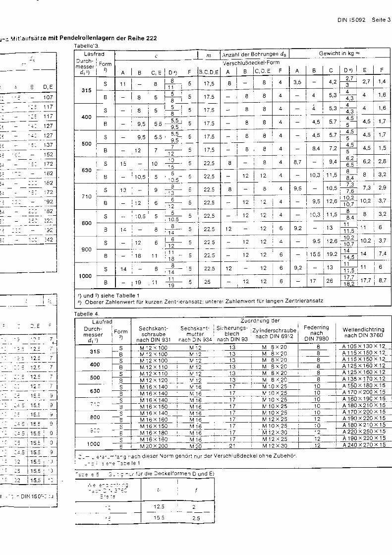
r - . M i t lau lse l ze mi t Pende l ro l len lagetn der Re ihe 222Tabe l le '3 .
D, E
107
152
1tt2
1 7 2
22i:
'42
Tabe l l e 4
: : : : 1 a . : )
1 1 7
1 1 7
Lauf rad
messer I ro"lm
d ' ' ) I 1
c Anzahl der Bohrungen d8 Gewicht in kg -
A B C , E D ' F
' /erschluBdeckel-Form
A l B c , D , E F c D 4 ) I E I F
s 1 l 81 1 |
- 8 8 4 4 2t 7
2,7 1 , 43
I 8 8 8 4 44
44.3
400S 8 B 8 4 4 5.3
44,3
B 5,5 r / , c 8 8 4 4 ,54.5 4 .5 ' t,75
500S 9.5 I 8 4 5.7
4 .54 ,5 1 , 7
5
B 12 77 -
1 2I B 4 8,4 7 ? 4 . 5
5
630S
B
r 0 1 0 2 2 . 5 B 8 4 8,7 9 ,46.26 .5 6 ,2 2 .4
1 0 , 5 12 1 2 4 1 0 , 3I8.4
8
7 1 0s 1 3 22.5 8 8 1 0 . 5
7 .6
B 1 2 " 1 21 2 1 2 4 9,5
10.2tloT 10,2 3 ,7
800s 1 2 1 2 4
I I8 .4
B 22.5 1 2 1 2 6' 1 1
1 1 61 1 . s
900S 1 2 6 1 2
1 2 1 2 1 2 . 6t 1 0 , 2, 1 0 , 7
1A,2
B - 1 81 1 - 1 2 1 2 6 19.2
1 41 4
1000s 1 a 1 2 6
t 11 1
1 1 . 5
B 1 9t t - 25 1 2 1 2 6 1 7 26
1 7 . 714.2
17,7
r ) und 2 ) s i ehe Tabe l l e la ) Obe re r Zah lenwer t f i j r ku rzen Zen t r t e ransa tz r un te re : Zah lenwer t f i i r l angen Zen t r i e ransa tz
LaufradDurch-m esser
d t ' )
Fo rm? )
Sechskan t - Sechskan t -scn rauDe mu l l e r
nach D IN 931 nach D N 934
Z u o r d f u n g d e rsi (herungs- zv,"oe,scnrauoe ie f l l r jng
nu#bji.] gs nacr- DrN 6s12 Dt;,j TsBoWel lend i ch t r i ngnach D IN 3760
SB
M 1 2 x 1 0 0 M 1 2 1 3 M 8 x 2 0 I A 1 0 5 x 1 3 0 x 1 2M 1 2 x 1 O 0 M 1 2 1 3 M 8 x 2 0 I A 1 1 5 x 1 5 0 x 1 2
400s M 1 2 < 1 0 0 U ' , 2 1 3 M 8 x 2 0 8 A 1 1 5 x 1 5 0 r 1 2
B M 1 2 x 1 l 0 M 1 2 1 3 M 8 x 2 0 a A 1 2 5 x 1 6 0 x 1 2
500s M 1 2 x 1 1 0 M 1 . 2 1 3 M 8 . 2 0 8 A i 2 5 X 1 6 0 x 1 2
B M 1 2 x 1 2 0 M 12 1 3 M 8 x 2 0 8 A 1 3 5 x 1 7 0 x 1 2s
630 BM 1 6 x 1 4 0 v : 6 1 7 V 1 0 ' 2 ) 1 0 A 1 5 0 x 1 8 0 x 1 5M 1 6 x 1 4 0 M 1 6 1 7 V 1 0 . 2 5 1 0 A 1 7 0 x 2 0 0 x 1 5
S7 : C B
M 1 6 x 1 4 0 M 1 6 1 7 M 1 0 x 2 5 1 0 A 1 6 0 x 1 9 0 x 1 5M t 6 x 1 5 0 1 7 N t 1 0 x 2 5 1 0 A 1 8 0 x 2 1 0 x 1 5
8oo +M t 6 x 1 4 0 t4 1 7 M 1 0 x 2 5 1 0 A 1 7 0 \ 2 0 0 \ 1 5M 1 € i x ' 1 6 0 M 1 7 M 1 2 . 2 5 1 2 A 1 9 0 x 2 2 0 x 1 5
I M 1 6 x 1 5 0 1 7 M 1 0 x 2 5 1 0 A 1 8 0 x 2 1 0 x 1 5M 1 6 x 1 8 0 r6 1 7 M 1 2 x 3 0 1 2 A,220 x25O )< 15
1 0 0 cM 1 6 x 1 6 0 M t 6 1 7 M 12x25 1 2 A 1 9 0 x 2 2 0 x 1 5M 20 . 200 M20 21 M 1 2 v 3 0 1 2
: , - . ' . . , - ' a ' . . acn d iese r No rm gehb r t n ! r de r Ve r j ch luBdecke l ohne Zubehd r '
: . D l . l 150 r : : : J
= a + 2 = - J - ' . : ^ - t : J t o e D A c l e i ' o r m e l D u n d E l

i i t e 4 D IN 15 092
VefschluBdeckel f0r Treib- und Mitlaulsetze '-
Tabelle 6.
Laufrad
Durch-mes se f
d t ' )
Form,)
t8
C , D , E F A B l C , D , E : F
?rsch luBdec l
A B
e l -Fo rm
C , D , E I F B l c , D , E F B
3 1 5s r 95 1 9 5 1 3 5 230 230 170 170 1 1 5 1 5 6 102 1 1 5
B 215 250 250 1 9 0 1 9 0 125 174 1 7 4 1 1 2 125
400s 215 215 250 250 1 S 0 1 9 0 125 174 1 7 4 ' | 12 125
240 240 275 275 1 6 5 215 215 125 201 201 1 1 2 125
500244 240 1 4 5 275 275 1 6 5 215 215 125 201 201 1 1 2 125
274 274 t 6 c 3 1 5 210 240 240 1 6 0 215 215 1 4 6 1 6 0 1 3 -
630S 270 270 1 8 5 3 1 5 3 1 5 214 240 240 1 6 0 215 215 1 4 6 1 6 0
3 1 0 3 1 0 3 5 5 220 2AO 280 1 7 0 255 255 1 5 8 1 7 0 1 5 :
7 1 4S 290 - 290 1 9 5 335 335 220 260 260 174 235 235 1 5 8 170
B 330 330 1 9 5 375 220 300 300 170 275 2 7 5 1 5 8 174 1 6 :
800s 3 1 0 3 1 0 1 9 5 355 220 280 280 170 255 255 1 5 8 170
B - 350 260 395 395 290 320 320 230 295 295 230 1 : :
900s 330 330 1 9 5 375 375 224 300 300 170 275 1 5 8 174
B 390 390 264 _ 435 435 290 - . 3 6 0 360 230 335 335 216 234 1 9 2
1000 !B
350 - 350 I 260 395 395 290 320 230 295 295 230 1 7 2
440 444 260 500 500 290 376 i 376 230 222
Fe t tged ruck te Zah lenwer te s i nd zu bevo rzugen .r ) N a c h D I N 1 5 0 7 02 ) S : schma le Fo rm
I = breite Form
Tabe l l e 7 -
Laufrl
Durch-messer
d t t )
l o
Form2)
do d tz u 2 U3 t1 fa
. . i D ' E" I H83)
, 8 , C , F
Versch luBd
r e ] o e
c kel- Fo rml
B i c D F A B I C , D , E F c l D , E F
3 t 5s 1 i 5 120 1 4 1 3 5 M I 9 1 5 1 2 1 0 12,5
125 1 3 0 1 4 5 M 8 1 5 I 22 1 5 1 2 1 2 1 0 12,5
400s 125 1 3 0 1 4 1 4 5 M B 1 5 I l 4 1 6 , 6 22 1 5 1 2 1 2 1 0 1 2 , 5
125 1 5 0 145 M 8 9 12 1 6 , 6 22 1 5 1 2 1 2 1 0 12.5 7
500s 125 1 5 0 1 4 5 M 8 I 12 22 1 2 1 2 1 0 12,5
1 6 0 1 6 0 1 8 1 8 5 M 10 '181 ' , I 27 1 9 1 4 23 12,5 s
S 1 6 0 1 6 0 1 8 M 1 0 1 B t l 27 1 9 1 4 l 4 23 12,5 I
170 1 8 0 r 8 1 9 5 Nr 10 1 8 ' 1 1 20 1 9 s
710s 1 7 0 174 1 8 1 9 5 M 1 0 1B 1 1 1 9 , 6 27 1 9 22 I
1 7 0 1 9 0 1B 1 9 5 M 10 ' t 1 1 8 1 7 30 1 9 I
800s 170 1 8 0 1B 1 9 5 I'il 10 1 8 1 1 20 't9 1 4 I
B 230 200 1 8 264 M 1 2 1 9 , 6 29 1 9 1 5 25 '10
900s 1 7 0 1 9 0 1B 1 9 5 M 1 0 1 l 1 8 1 7 30 1 9 I
B 234 224 1B 260 M 1 2 2A 1 4 20 1 8 1 9 1 4'15 29 1 0
1000s 230 200 1 8 260 M 12 20 1 e 1 9 1 4 25 1 0
B 230 254 264 M 1 2 20 23 20,6 22 24' 15 33 1 0
' ) und 1 ) s i ehe Tabe l l e 63 i Be i ; E inbau de r We l l end i ch t r i nge i s t d i e Lage de r D i ch t i i ppen i n Abwe ichung zu D IN 3760 nach de r b i l d l i chen Da rs te l l ung i n D IN 15 090 zu
beach te n .
I
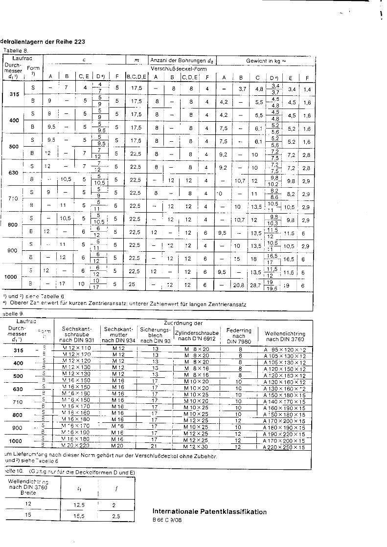
delrollenlagern der Reihe 223Tabe l le 8
LaufradDurch - F^ ._messe r ' " . .
d.1t\ i ' )
c Anzahide r Boh rungen Gew ich t i n kg =
e l c , e l o r l rVerschJuB'leckel-Form
r l e ] c , o , e i r e ] e c ] o . t E Fs 7 l 4
a ? 5 1 7 5 8 I 4 ,81 3 , 4 3 ,4 1 , 4
I 5 5 5 8 I 4 4 .5 4,5I 4.8
400
q - 5 58 8 t 2 4.5
4 ,59 4,85
55 8 8 6 , 19 .5
500S 5
55 1 7 . 5 I 8 4 1 , 65 .6
1 2 77
5 22.5 I B 4 1 0 7,2 2 .81 2
s 12 77
5 8 8 4 1 0 7.27 ' , ) 2,41 2 7.5
B - 1 0 , 5 55 i
1 0 . 5 5 12 1 2 4 1 2 1 0 2t a
7 1 0S
I
I 5 II
5 22,5 8 4 r 0 I l
1 1 55
t l 5 1 2 1 2 4 1 0 1 0 , 5 t o
S
E800
1 0 , 5 55 l
1 0 . 55 22,5 1 2 4 1 2
i 2 61 2 22,5 1 2 6 ; _ I L . J 6
900S - t ] 5 5
5 1 2 1 0 1 0 , 5t l
1 0 , 51 1
1 2 61 2 5 12 1 2 6 1 5 1 8 1 6 . 5
61 7
10006 6
1 25 1 2 1 2 6 6
_ I 1 7 1 0 - - c 1 2 20,81 9 5 1 9 6
' ) und r ) s re :e :abe l l e 61 obe re r za : enwer t f r i r ku rzen zen t r i e ransa tz r un te re r zah renwar t f i . r r r angen zen t r i e ransa tz
abe l l e 9Lau l f ac
Durch -messer
' t- i -
d t ' )
S e ch skan t -sch rau oe
nach DIN 931
Zuc rdnung de rS e c h s k a n t . S ; c h e r u n o s - - . .
mu l t e r b recn zy l l noe rscn raubenach DtN g34 n".n
-olN so nach o'N 6912
t " l : : ' ; "n we lend ich t r insoti..r lgeo I nach DIN 3760
M 1 2 x 1 ' 1 0 M 1 2 1 3 M 8 X 2 O 8 A 9 5 x 1 2 0 x 1 2M 1 2 x 1 2 0 M 1 2 1 3 M 8 X 2 O I A 1 0 5 x 1 3 0 x 1 2
400 M 1 2 ' t 1 2 0 M 1 2 1 3 M 8 X 2 O I A 1 0 5 x 1 3 0 x 1 2M 1 2 x ' 1 3 0 M 1 2 M 8 . 1 6 I A 1 2 0 x 1 5 0 x 1 2
500 I f!11?.11!! .M 1 6 x 1 5 0 M 1 6 1 7
M 8 X 1 6 I A 1 2 0 x 1 5 0 x 1 2l,,l 10 x 20 1 0 A 1 3 0 x 1 6 0 x 1 2
630 r , r 1 6 x ' 1 5 0 M 1 6 1 7 M 1 0 x 2 0 1 0 A 1 3 0 x 1 6 0 x 1 21 7 M 1 0 x 2 5 1 0 A 1 5 0 x 1 8 0 x 1 5
M 1 6 x 1 5 0 M 1 6 1 7 M 1 0 x 2 0 1 0 A 1 4 0 x 1 7 0 x 1 5V 1 6 \ 1 7 0 M 1 6 1 7 t\4 10 x 25 1 0 A 1 6 0 : 1 9 0 . 1 5
800 I f v r 1 6 x 1 6 0 M 1 6 1 7 M 1 0 x 2 5 1 0 A 1 5 0 x 1 8 0 x 1 5M 1 6 x 1 8 0 M 1 6 1 7 M 1 2 x 2 5 1 2 A 1 7 0 x 2 0 0 x 1 5
900 \ r 1 6 x 1 7 0 M 1 6 1 7 M 1 0 x 2 5 1 0 A 1 6 0 x 1 9 0 x 1 5v 1 6 x 1 9 0 M 1 6 1 7 M 12x25 1 2 A 1 9 0 x 2 2 0 x 1 5
l ooo i v 1 6 x 1 8 0 M 1 6 1 7 M 1 2 x 2 5 1 2 A 1 7 0 x 2 0 0 x 1 5u2a x220 M20 2 1 M 1 2 x 3 0 1 2 4220 . 250 ' 15
!m L ie fe ru r j ' i a . g nach d iese r No rm geh6 r t nu r de r Ve rsch luBdec l (e l ohne Zubeho r .und 2 ) s i ehe i ace t e 6
' e l l e l 0 . (G ! 1 rg j r { r r tU r d i e Decke l f o rmen D und E )
We l l end i ch i . . r gnach D IN 3760
B re i t e
Internat ionale Pate nt k lassi f ikat ionB 66 C 9/08

1( '
l
E
t
;
z
E
a
E
I'
Mlnne lmannDemag
HiittentcchnlkMGte l lgewlnnun l
KraneTreib- und Mit laufsdtze
Laufrader
D I N15 093
Cranes ; d r i ven and ro ta t i ng ax les ; r a i l whee l s
Appa re i l s de l evage : ess ieux conmandds e t t ou rnan ts ; r oues po r teuses
MaBe in mm
1 Anwendungsbereich und ZweckLau f rede r nach d iese r No rm werden au l We l l en nach D IN 15091 au fgesch rump t t . um
Tre ib - und M i t l au f sa t ze nach D IN 15090 he rzus te l l en .
2 MaBe, BezeichnungDie Lau f rede r b rauchen de r b i l d l i chen Da rs te l l ung n i ch t zu en t sp rechen ; nu r d l e ange -
aebenen MaBe s ind e inzuha l t en .
Tabelle 1. Formverschl i :sgelung
Fo rm buchs tabe Erkla.ung
s schmales Laufrad
B breites Laufrad
H Lauf rad mit Spurkrdnzen
Lauf rad ohne Spurkranze
M Laufrad mit Radreifen
K Laufrad ohne Radreifen
Lau f r ad m i t D ruckd l -P reBve rband
Laulrad ohne Druckol-PreBverband
Fortsetzung Seite 2 bis 5
NormenausschuB Masch inenbau (NAM) im DIN Deutsches lns t i tu t f i i r Normung e v
Vcrvielfdltigung lt. DNA-Mcrkblott 3, Zift. I
DK 621.873-25 : 621.824 : 629.1 1.012.354 D E U T S C H E N O R I V Ju l i 1982
1982 tueisgt.5ver l r -Nr 0005
A le r .vs rkau l der Normen durch 8e ! th V6r lag GmbH. 86n in 30oT.a2
D/N 15 093

? i t e 2 D IN 15 093
2.1 Laufreder.tiir Treib- und Mitlaulsiitze mit Spurkranzen ohne Radreifen
Form SHKOForm SHKE (dargestellt)
Beze i chnung e ines b re i t en5 uchs taben nach Tabe l i e
'Yabelle 6):
Tabe l l e 2 .
Form BHKD (dargestellt)Form BHKE
Lau f rades (B ) , m i t Spu rk renzen (H ) , ohne Rad re i f en (K ) , m i t D ruckd l -P reBve rband (D ) - Fo rm-
1 - von DL rchmesse r d r : 630mm und B re i t e b r = 110mm, aus GS-623 (Kennzah l 20 nach
Laufrad DIN 15 093 - BHKD 630 x 110 - 20
Lauf rad
Durchmesserd t t ) Form' )h 9
b t 2 )
H 1
4 5 l5
Gewich t ' )i nkg
3 1 5S 55 90 350 1 1 0 1 7 5 270 1 1 0 38
B 65 1 1 0 350 120 1 9 0 270 1 1 0
400S 65 1 1 0 440 120 1 9 0 345 1 4 0
B 90 1 4 0 440 1 3 0 205 345 1 4 0 93
500s 1 1 0 540 1 3 0 205 435 1 4 0 1 1 3
B 90 1 4 0 1 4 0 224 435 1 4 0 142
630120 680 1 6 0 255 560 1 5 0 1 9 3
B 1 ' 10 1 6 0 680 1 8 0 245 560 1 6 0 251
714s 90 ' 140 760 170 270 630 1 8 0 284
B 1 6 0 210 760 1 9 0 300 210 4 1 4
800S 90 144 850 1 8 0 245 7 1 0 1 8 0 357
I 1 6 0 210 850 2AO 7 1 0 210
900S 90 1 4 0 1 9 0 300 805 1 9 0 428
1 6 0 210 950 230 805 210 658
1000s 90 1 4 0 1 0 5 0 200 324 900 1 9 0 550
B 1 6 0 210 1050 250 395 900 210 809
Fet taedruck te Zah lenwer te s ind zu bevorzugen') S: schmale Form
B = bre i te Formr) Nach DIN 15 070,i l. l-." i ir i i i ;n["oe Laufrdder mit S purkranzen; kleinere Werte fi ir f i ihrende Laufrader mit S purkranzen sind 2u verein-'
6u i l j i . ou" MaB b1 is t ber n ich t f i . jh renden Lauf radern mi t Spurkrdnzen g .c jBer a ls be i f i j h renden Lauf rddern auszu-fi ihren.Lir.rtt iacnenprotite und Zuordnung der Kranschienen zum La ufraddu rch m esser nach DIN 15 072.
3) Anwarmtembera tur f i . l r Radkdrper -280 b is 3OO'C be i 20"C Ra!mtempera tur . Das E in f0hrungssp ie l (F i jgesp ie l ) be t rag t' J "o" i . i i o " i i " " " ia " r rOt t ) m 'm O'e F i ige f tdchen mi rssen f re ivon Schmrermi t te l Jnd so lcne l Verur re 'n igL lgen se in 'd ie den Haf tbe iwer t ung i ins t ig bee in f lussen konnen
" ) cewich t , bezogen au f : - b r -a r- 50b6 bes Vo l 'querschn i t ts des Radkdrpers be i Lauf radern ohne Radre i fen- 70o lo des Vo l ldqerschn i t ts des Radkdrpers be i Lauf r i idern mi t Radre i fen- Q : 7 ' 8 5 k g / d m '
Genauere G ewich tsanga be i t s ind abhang ig von der Gesta l tung und dem Hers te l l ver lahren .

DIN 15093 Se i te 3
2.2 Lautreder tUr Treib- und M itlautsStze mit Spurkrenzen mit Radreilen
rForm SHMDForm SHME (dargeste l l t )
Form BHMD (dargestellt)Form BHME
(€
B e z e i c h n u n g e i n e S b r e i t e n L a u t r a d e s ( B ) ' m i t S p U r k r : i n z e n ( H ) . m i t R a d r e i f e n ( M ) ' m i t D r U c k o | - P r e B v e r b a n d ( D ) _ F o r m -buchs taben nach Tabe l l e 1 - von D u rchmesse r d1 = 630 mm, B re i t e ' 1 = 110 mm' Lau f radko rpe rn aus GS '62 3 (Kennzah l 20
nach Tabe l l e 6 ) und Rad re i f en aus C 60 N (Kennzah l 11 nach Tabe l l e 6 ) :
Laufrad DIN 15093 - BHMD 630 x 110 - 20 - 11
Tabe l le 3 .
F+
Laufrad
Durchmesser Id 1 \ J i F o r m . )
bt') d : 3 )
H T
I 5
Gewich t l )i nKg
400s 65 1 1 0 80 440 120 1 9 0 3 1 0 1 4 0 93
90 1 4 0 1 1 0 440 1 3 0 274 3 1 0 140 1 2 2
500S 65 1 1 0 80 540 1 3 0 205 330 400 1 4 0 138
B 90 1 4 0 1 1 0 540 1 4 0 400 1 4 0 182
630s 75 120 90 680 1 6 0 255 450 520 1 5 0 235
B 1 1 0 1 6 0 1 3 0 680 180 285 450 520 1 6 0 323
7 1 090 1 4 0 1 0 0 1 7 0 270 590 1 8 0 332
1 6 0 214 170 1 9 0 300 5 1 0 590 214 522
80090 1 4 0 1 0 0 850 1 8 0 245 580 190 4 t 1
1 6 0 210 174 850 200 324 s80 210 656
900S 90 1 4 0 1 0 0 950 1 9 0 300 665 1 8 0 5 1 5
B 1 6 0 210 170 950 230 665 210 429
1000s 90 1 4 0 1 0 0 1050 200 324 750 850 1 9 0 621
B '160 210 170 1050 250 395 750 850 210 1006
' ) S iehe Tabe l l e 2t ) b i s r ) s i ehe f abe l l e 2s i Sch rump fs i t zangaben und Rad re i f en nach D IN 15083
e i te 4 DIN 15093
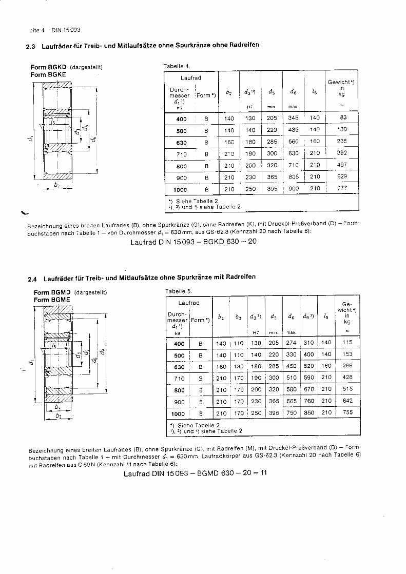
2.3 Laufreder.fi ir Treib- und Mitlaulsatze ohne Spurkinze ohne Radreifen
Form BGKD (dargestellt)Form BGKE
Tabe l l e 4
Laufrad
Durch -messe r Fo rm ' )
d t ' )h 9
u 2
H T
s 5 d5 l5
Gewich t 1 )i nkg
400 B 1 4 0 1 3 0 205 345 1 4 0
500 B 1 4 0 1 4 0 220 1 4 0 1 3 0
B 1 6 0 1 8 0 245 1 6 0 235
7 1 0 I 210 1 9 0 300 630 210 392
800 B 210 200 320 7 1 4 210 497
900 B 214 234 805 214 629
1000 I 210 250 395 900 210 777
. ) S iehe Tabe l l e 2r ; , : ; und . ) s i ehe Tabe l e 2
Beze i chnung e lnes b re i t en Lau f rades (B ) , ohne SpUrk ranze (G) . ohne Rad re i f en (K ) , m i t D ruck6 l - P reBve rban d (D ) - Fo rm-
buchs taben nach Tabe l l e 1 - von Du rchmesse r d l : 630 mm. aus GS-62 3 (Kennzah l 20 nach Tabe l l e 6 ) :
Laufrad DIN 15093 - BGKD 630 - 20
2.4 Laufrader tiir Treib- und Mitlaufsatze ohn'e Spurkr5nze mit Radreifen
Tabe l l e 5 .
Lau
Durch-messer
dt ' )h 9
:rao
Form' )
H 7
d 5 l5w i c h t 4 )
i n
400 B 1 4 0 | 1 1 0 1 3 0 205 274 3 1 0 1 4 0 1 1 5
500 B 140 1 1 0 140 220 330 400 140 1 5 3
630 B 1 6 0 1 3 0 1 8 0 285 524 1 6 0
7 1 0 B 210 174 1 9 0 300 5 1 0 590 210 424
s00 214 1 7 0 2AO 320 580 670 210 5 1 5
900 210 1 7 0 230 365 665 214 642
1000 210 1 7 0 254 395 850 210
' ) S iehe Tabe l l e 2' ) , 3 ) und . ) s i ehe Tabe l l e 2
Beze ichnung e ines bre i ten Lauf rades (B) , ohne Spurkranze (G) , m i t Radre i fen (M) , mi t Drucko l -PreBverband (D) - Form-
buchs taben nach Tabe l le 1 - m i t Durchmesser d i = 630mm Lauf radkorper aus GS-623 (Kennzah l 20 nach Tabe l le 6 )
mi t Radre i fen aus C 60 N (Kennzah l 11 nach Tabe l le 6 ) :
auf rad DIN 15 093 - BGMD 630 - 20 - 11
Form BGMD (darges te l l t )Form BGME
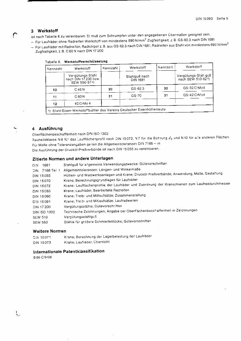
3 Weikstoffl s t nach Tabe l le 6 zu vere inbaren Er muB zum Schrumplen
- Fr i r Lauf rader ohne Radre i fen Werks to t f von mindes tens
- F i i r Lauf rader mi t Radre i fen ' Radkorper z B aus GS-62 3
Zugfes t igke i t , z . B . C 60 N nach OIN 17 200
DIN 15093 Se i te 5
unter den angegebenen lJbermaBen gee ignet se in
590 N/mm2 Zugfes t igke i t , z . B . G5-62 3 nach DIN 1681
nach DIN 1681;Radre i fen aus Stah lvon mindes tens 690 N/mm2
Tabelle6. werkstoffverschli isselung
4 AusfiihrungOber f l achenbescha f fenhe i t nach D IN ISO 1302
Rauhe i t sk l asse N 8 f i j r das Lau f f t achenp ro f i l nach D IN 15072 , N 7 i i j r d i e Boh rung d3 und N 1o f i i r aL le ande ren F ldchen
F i l r MaBe ohne To le ranzangaben ge l t en d ie A l l geme in to le ranzen D IN 7168 - m
D ie Aus f t j h rung de r D rucko l -P reBve rbande i s t nach D IN 15055 zu ve re lnba ren '
Zitierte Normen und andere Unterlagen
DlN 1681 S tah lguB fU r a l l geme ine Ve rwendungszwecke ; G i i t evo rsch r i f t e n
D IN 7168 Te i l 1 A l l geme in to le ranzen ; Ldngen - und W inke lmaBe
D l N l 5 o 5 5 H i l t t e n - u n d w a l z w e r k s a n l a g e n L l n d K r a n e ; D r u c k d l - P r e o v e r b d n d e ; A n w e n d u n g ' l ' 4 a B e ' G e s t a l t u n g
DIN 15070 K rane ; Be rechnungsg rund lagen f i l r Lau f rade r
D 1 N 1 5 O 7 2 K r a n e ; L a u f f l d c h e n p r o f i l e d e r L a u f r d d e r u n d Z u o r d n u n g d e r K r a n s c h i e n e n z u m L a u f r a d d u r c h m e s s e r
D IN 15083 K rane ; Lau f rdde r ; Bea rbe i t e te Rad re i f en
D IN 15090 K rane ; T re ib - und M i t l au f sa t ze ; Zusammens te l l ung
DIN 15091 K rane ; T re ib - und M i t l au f sa t ze ; Lau f radwe l l en
DIN 17 2OO Vergi i tungsst?ihle; G i j tevo rsch r j f te n
D l N l S O l 3 0 2 T e c h n i s c h e Z e i c h n u n g e n ; A n g a b e d e r O b e r f l a c h e n b e s c h a f f e n h e i t i n Z e i c h n u n g e n
SEW 5lO Ve rg i .1tu n gsstah lg uB
SEW 550 S teh le f i . i r g roBe re Schmiedes t i j c ke ; G i j t evo rsch r i t t en
weitere NormenDIN 15071 K rane ; Be rechnung de r Lage rbe las tung de r Lau l rdde r
D IN 15073 K rane ; Lau f rade r ; LJbe rs i ch t
lnternat ionale Patentklassi f ikat ionB 66 C 9/08
Werkstott
Verg i j tungs-Stah guBnach SEW 510-62 s)Stah lguB nach
DtN 1681Ve rg i j tu ng s- S tah I
nach D IN 17 200 bzw .sEw 550-s7 6)
' r 0 c 4 5 N3 1 G S - 4 2 C r M 0 4
' 12 j 42aMa 4
6 ) S tah l - E i se n -Werks to f f b l a t t e r des Ve re ins Deu tsche r E i senh i i t t en leu te
{
' I
E
g
o
IE
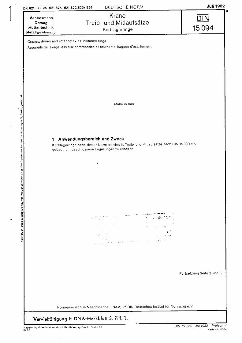
MannesmannDomag
HiittenlcchnilMc la l lgewl r rn r . r r
KraneTreib- und Mit laufsi i tze
Korblagerr inge
DIN15 094
Cranes; driven and rotating axles; distance rings
ApDare i l s de levage; ess ieux command6s e t tournants ; bagues d 'ecar tement
MaBe i n mm
1 Anwendungsbereich und ZweckKorb lage r r i nge nach d iese r No rm werden i n T re ib - und lV i t l au f sd t ze nach D IN 15090 e in -
gebau t , um gesch lossene Lage rungen zu e rha l t en
For tse tzung Se i te 2 und 3
NormenausschuR l \y 'asch inenbau (NAM) lm DIN Deutsches Ins t i tu t f i l r Normung e V
Vcwiclfdlt igung l t . DNA-Mcrkblott 3, Zif f .
DK 621.873-25 :621 .824.621.a22.823/ 824 DEUTSCHE NO RN, l Jul i 1982
Jul 1982 Preisgt. 4V . r l r ' N r 0 0 0 4
Al le rnvorkaut de . Nornen d ! rch Beu lh Ver laq GmbH, Ben in 30o 7 8 2
DIN 15 094
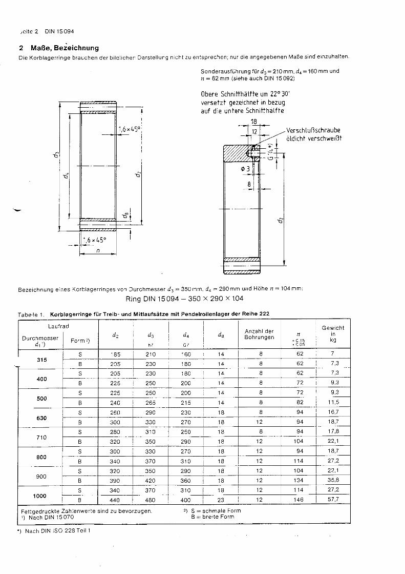
,e i te 2 DIN 15 094
2 MaRe, BezeichnungDie Ko rb lage r r i nge b rauchen de r b i l d l i chen Da rs te l l ung n i ch t zu en l sp rechen ;nu r d i e angegebenen MaBe s ind e inzuha l t en .
Sonde raus t i . l h rung f i t d3 :210 mm, d4= 160 mm undn : 6 2 m m ( s i e h e a u c h D I N 1 5 0 9 2 )
0bere Schnitthiittie um 220 30'versetzt gezeichnei in bezugauf die untere Schnit thdtf te
Versch tu{lschraubedtd ich i verschweiBt
Beze i chnung e ines Ko rb lage r r i nges von Du rchmesse r d . : 359 t a , d t = 290 mm und HOhe n = 104 mrn :
Ring D IN 15 094 - 350 x 290 x 104
Tabelle 1. Korblagerringe t i i r Treib- und Mit laufsatze mil Pendelroi lenlager der Reihe 222
1 , 6 x 4 5 0
1 , 6 , 4 5 '
Laufrad
Durchmesse r ]
Fo rm r )G /
Anzah l de rBoh rungen
n+ 0 , 1 5+ 0 .0s
G ew ic h ti nkg
3 1 5S 1 8 5 210 1 6 0 i 1 4 I 62 7
B 205 230 1 8 0 1 4 8 62 7 3
400S 205 230 1 8 0 8 62 7 3
B 225 250 204 t 4 8 7 2
500s 2 2 5 200 8 7 2 9,3
B 244 8 a2 I | C
s 264 294 234 1B 8 94 16.7
B 300 274 1 2 94 18,7
7 1 0S 2AO 3 1 0 250 8 94 17 ,A
B 324 350 290 1 8 1 2 1 0 4
800S 300 330 270 1 8 1 2 94 1A,7
340 370 3 r 0 1 8 1 2 1 1 4 27 ,2
900s 320 350 290 1 8 1 2 1 0 4
B 390 420 360 1 2 134
1000S 340 370 3 1 0 1 8 1 2 1 1 4 27 ,2
B 440 480 400 1 2 1 4 6 57 ,7
Fet tgedruck te Zah lenwer te s ind zu bevorzugen.1 ) N a c h D I N 1 5 0 7 0
,) S = schmale FormI = b rer te Form
' ) Nach D IN ISO 228 Te i l 1
DIN 5 094 Se i te 3
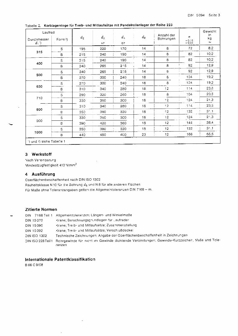
Tabelle Z Korblagerringe f i i r Treib- und Mit lauts: i ize mit Pendelrol lenlager der Reihe 223
Laufrad
Durchmesse r Fo rm 2 )h 7 G T
Anzah l de rB o h r u n g e n
n+ 0 . 1 5+ 0 0 5
Gewich tt nkg
3 t 5s 1 9 5 220 170 8 7 2
B 215 244 1 9 0 1 4 I 82 10,2
400s 215 24A 190 14 I B2 10,2
240 265 2 1 5 1 4 9 2 12.9
500S 240 265 215 I 1 ? q
B 270 300 240 8 1 0 4 1 9 , 2
630s 270 300 240 I 1 0 4
340 2AO 1 2 1 1 4
7 1 0s 290 32A 260 1B I 1 0 4 24,5
330 360 300
800S 3 1 0 340 2AO 1 2 23.5
B 350 380 320 1 2 132
900S 330 360 300 1 2
390 424 360 1 2 144 38 ,4
1000S 350 380 320 1B 1 2 132
B 440 480 400 23 1 2 1 6 6
i \ , ' . . 1 l r c i . h a T , h a l l a 1
3 Werkstoff\ ach Ve 'e ' r ba ru rg
M indes t zug fes t l gke i t 410 N /mm2
4 AusfiihrungOber f l echenbescha f fenhe i t nach D IN ISO 1302
Rauhe i t sk l asse N 10 f i j r d i e Boh rung dB LJ .d N I f i i r a l l e ande ren F ldchen
F i j r MaBe ohne To le ranzangaben ge l t en d ie A l l geme in lo l e ranzen D N 7168 - m
Zitierte NormenDIN 7168 Te i l 1 A geme in to le ranzen ; L? tngen - und w inke lmaBe
DIN 15070 K rane ; Be rechnungsg rund lagen f i j r Lau f rdde r
D1N 15090 K rane ;T re b - und M i t l au f sd t ze ; Zusammens te l l ung
DIN 15092 K rane ;T re lb - und M i t au f sa t ze ; Ve rschLuRdecke l
D IN ISO 1302 Techn i sche Ze i chnungen ;Angabe de r Obe r f lAchenbescha f fenhe i t i n Ze i chnungen
DIN lSO22BTe i l l Roh rgew inde f i j r n i ch t im Gew inde d i ch tende Ve rb indungen ; Gew inde -Ku rzze chen , MaBe und To ie -
l anzen
lnternat ionale Patentklassi f ikat ionB 66 C 9/08
DK 621.873-25 :621.824 i 621.887 DEUTSCHE N O R lv l Jul i 1982
E
E
'
M an neam an nDcmrg
H!tlontachnikV e l a l l q e w l n n u n c
KraneTreib- und Mit laufsatze
Siche rungssche iben Buchsen N ippe l 15 095DIN
Cranes; d r iven and ro ta t ing ax les ; secur ing d iscs , bushes , n ipp les
Appare i l s de levage; ess ieux commandds e t tournants ; bagues, manchons, n ipp les
MaBe in mm
1 Anwendungsbereich und ZweckS iche rungssche iben , Buchsen und N ippe l nach d iese r No rm werden fU r den E inbau an Lau f radwe l l en nach D IN 15091
und Ve rsch lu Bdecke l n nach D IN 15092 de r T re ib - und M i t l au f sa t ze nach D IN 15090 ve rwende t . H ie rdu rch so l l d l e Aus -
tauschbarkeit dieser Tei le erreicht werden.
2 MaBe, BezeichnungDie E inze l t e i l e b rauchen de r b i l d l i chen Da rs te l l ung n i ch t zu en t sp rechen ;nu r d i e angegebenen MaBe s ind e inzuha i t en .
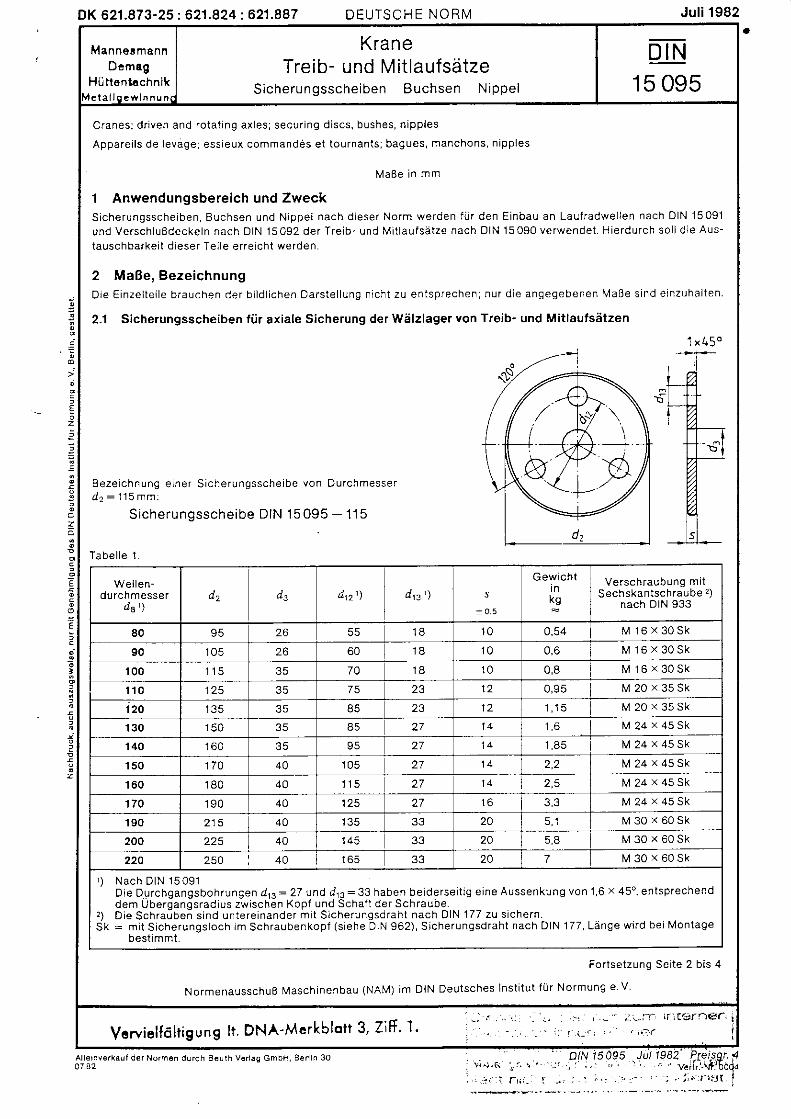
2.1 Sicherungsscheiben fiir axiale Sicherung der Welzlager von Treib' und Mitlautsatzen
1 x 4 5 o
Beze ichnung e iner S icherungssche ibe von Durchmesserd z : 1 1 5 m m :
Siche ru n gssche ibe D IN 15 095 - 115
l abe l l e 1 .
No rmenausschuB Masch inenbau (NAM) im
For tse tzung Se i te 2 b is
DIN Deutsches lns t i tu t f i j r Normung e v
Wel len-ou rcn messe r
da 'Jd p ' ) dr : ' ) s
Gewich ti nkg
Verschraubung mi tS ech skantsch rau be '!)
nach DIN 933
80 95 26 55 1 8 1 0 0,54 M 1 6 x 3 0 s k
90 1 0 5 26 60 1 8 1 0 0,6 M 1 6 ' 3 0 s k
1 0 0 35 70 1 8 1 0 0,8 M 1 6 x 3 0 S k
1 1 0 125 35 75 23 1 2 M 2 0 x 3 5 S k
120 1 3 5 35 85 1 2 1 , 1 5 M 2 0 . 3 5 S k'130 3 5 85 2 7 M 2 4 x 4 5 S k
1 4 0 1 6 0 35 27 M 2 4 \ 4 5 S k
1 5 0 1 7 0 4A 1 0 5 27 2,2 M 2 4 ^ 4 5 S k'| 60 180 4A 1 1 5 27 M 2 4 r 4 5 S k
170 1 9 0 40 1 2 5 27 M 2 4 . 4 5 S k
190 215 4A 1 3 5 33 20 M 3 0 x 6 0 S k
200 225 40 1 4 5 33 20 5,8 M 3 0 . < 6 0 s k
250 40 1 6 5 33 20 7 M 3 0 \ 6 0 S k
, ) Nach D IN 15 091D ie Du rchgangsboh rungen dE= 27 und d r : = 33 haben be ide rse i t i g e i ne Aussenkung von 1 ,6 x 45o , en t sp rechenddem Ubergangs rad ius zw ischen Kop f und Scha i t de r Sch raube .D ie Sch rauben s i nd un te re inande r m i t S i che rungsd rah t nach D IN 177 zu s i che rn .: m i t S i che rungs loch im Sch raubenkop f ( s i ehe D IN 962 ) , S i che rungsd rah t nach D IN 177 , Lenge w i rd be i Mon tage
bes t immt .
,)SK
Vcwielf6lt igung l t . DNA-Mcrkblott 3, Zif f ' 1- - r . . . . r : - r . . : ' : , - - : t - aa i f ) | . ' t r n@( ' i' " _ . - . - ; ; r : l - l : " " 1 1 r I
L l le rnverka ! l der Normsn durch B€! rh V6nag GmbH, Ben in 307 4 2
Sei te 2 DIN 15 095
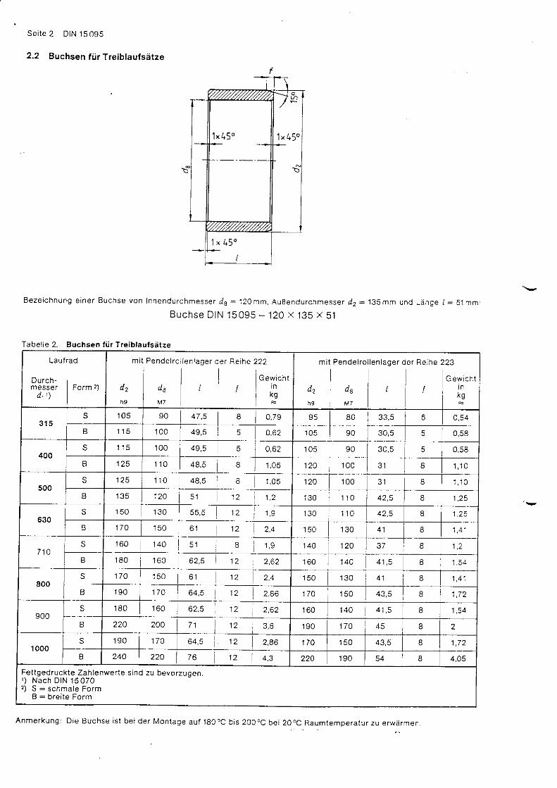
2.2 Buchsen fi i r Treiblaufs5tze
Beze ichnung e iner Buchse von Innendurchmesser ds : 120 mm, AuBendurchmesser dz = 13Smm und Lange l :5 jmm:
Buchse D IN 15095 - 120 x 135 x 51
Anmerkunq: D ie Buchse is t be i der fu lon tage au f 180oc b is 2oocc be i 20oc-Raumtempera tur zu erwarmen.
t x 9 ) -1 ' 4 5 o
1 ' 4 5 "
Tabelle 2- guchsen t i i r Treiblautsarze
LAUT
Durch-mesSer
d t ' )
rad
i r o r m )
m
u 2
h 9
t Pende l rc
l o ,l v z
l l en lage r de r Re ihe
' l l222
G ew ich tl n
r k a
m t
w2
h 9
Pen de l ro
de
l l en lage r
i L
i e r Re ihe
i l
223
Gew ch tLIni K q
1 0 5 90 47 ,5 I s 5 80 5
B 1 1 5 1 0 0 49,5 5 0,62 1 0 5 90
400S 1 1 5 1 0 0 49,5 5 o,62 1 0 5 90 30,5 5
125 1 1 0 48,5 B 1 , 0 5 120 1 0 0 3 1 I 1 , 1 0
500S 125 1 1 0 48,5 I I 1 , 0 5 120 1 0 0 8 1 . 1 0
B 1 3 5 124 5 1 1 2 1 2 130 1 1 0 8
630S 1 5 0 1 3 0 1 2 130 1 1 0 1 .25
B 1 7 0 1 5 0 1 2 1 5 0 1 3 0 I
7 1 4S
;
1 6 0 1 4 0 5 l 8 1 4 0 124 8 1 . 2
1 8 0 1 6 0 1 2 2,62 1 6 0 1 4 0 8
800s 170 1 5 0 1 2 1 5 0 1 3 0 8 1 , 4 1
a 1 9 0 1 7 0 64 ,5 12 174 1 5 0 8 1 7 4
900S 1 8 0 1 6 0 1 2 1 6 0 1 4 0 41 ,5 I
B 220 200 7 1 1 2 1 9 0 170 8 2
'1000 s 1 9 0 170 6 4 , 5 1 2 2,86 170 1 5 0 43,5 8
I 240 220 76 1 2 4.3 220 1 9 0 54 8 4,05
Fe t tged ruck te Zah lenwer te s rnd zu bevo rzugen .' ) N a c h D I N 1 5 0 7 02 ) S : s c h m a l e F o r m
B: b re i t e Fo rm
r ' r lN 15095 Se i te 3
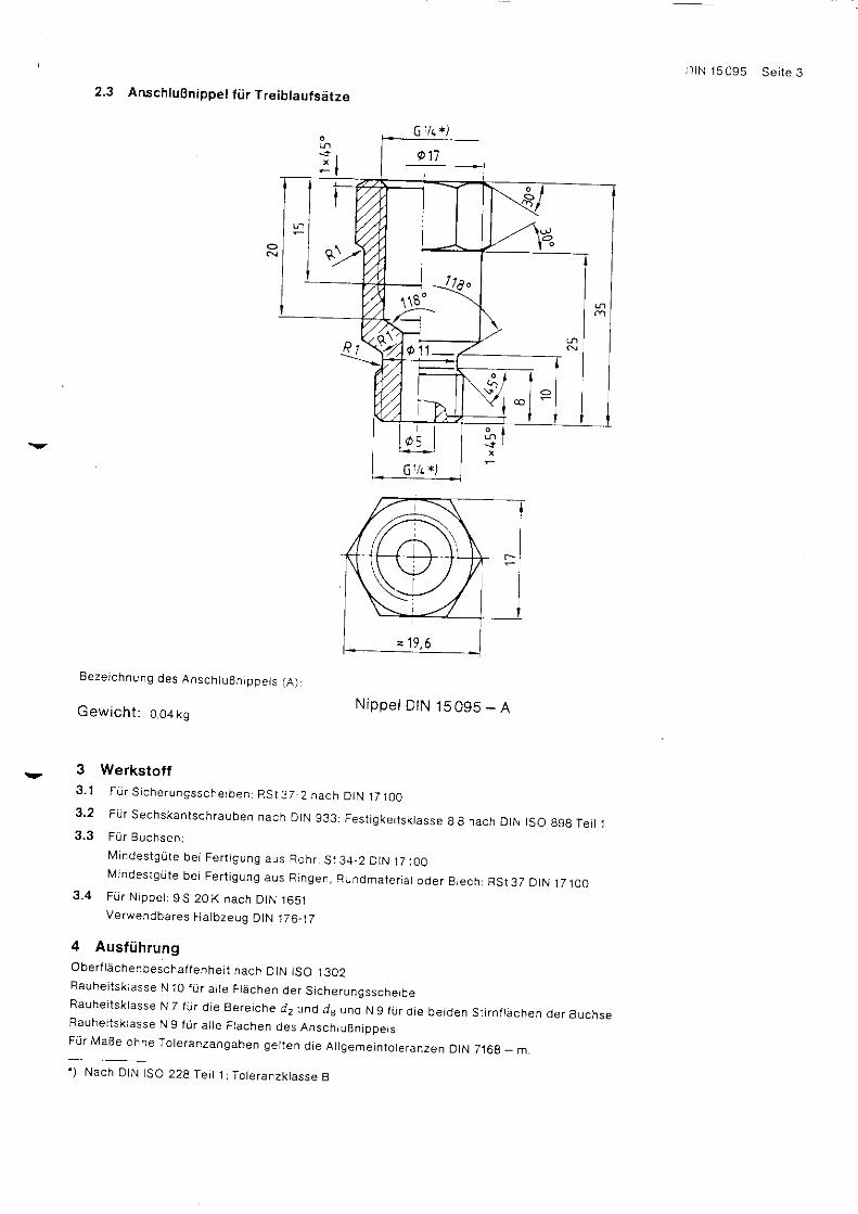
2.3 AnschluBnippet fii r Treiblaufsetze
Beze i chnung des Ansch luBn ippe l s fA )
Gewicht: o o+ *gN ippe l D tN 1S 095 - A
3 Werkstoff3 .1 F i j r S i che rungssche rben r RS t 37 2 nach D iN jT tOO3 ,2 F i i r Sechskan tsch rauben nach D IN g33 : Fes t i gke i t sk tasse B 8 nach D tN tSO 898 Te i t 13 ,3 FL i r Buchsen :
M indes tgd te be i Fe r t j gung aus Roh r S t34 ,2 D tN jT iOOL4 indes tg r i t e be i Fe r t i gung aus R ingen , R !ndma te r i a i ode r B rech :RS t37 D rN 17100
3 .4 F r j r N ippe t : 9S 20K nach D tN 1651Verwendba res Ha lbzeug D iN 176_17
4 AusfiihrungOber f l achenbescha f fenhe i t nach D IN tSO 1302Rauhe i t sk l asse N 1O f i . l r a l l e F lechen de r S i che rungssche rbeRauhe i t sk rasse N 7 f r i r d i e Be re i che d2 und ds und N 9 f u r d i e be iden s t i r n f l achen de r BuchseRauhe i t sk i asse N 9 t r j r a l l e F tdchen des Ansch tuBn ippe l sF i i r MaBe ohne To le ranzangaben ge l t en d ie A l l geme in to le ranzen D IN 7168 _ m .' ) N a c h D I N S O 2 2 8 I e r t 1 ; T o t e r a r z k t a s s e B
Sei te 4 DIN 15095
Zit ierte NormenDIN 176 B lanke r Sechskan ts tah l ; MaBe , zu lass ige Abwe ichungen , Gew ich te
D IN 177 S tah ld rah t ka l t gezogen ; MaBe , zu less ige Abwe ichungen ' Gew ich te
D IN 933 Sechskan tsch rauben ; Gew inde annehe rnd b i s Kop f ; Me l r i s ches Gew inde , Aus f t j h rung m und mg
DIN 962 Sch rauben und Mu t te rn ; zusa tz l i che Fo rmen und Aus f i j h rungen ; Bes te l l angaben und MaBe
DIN 165 1 Au toma tens tdh le , Techn i sche L e fe rbed ingunge ' ]
D IN 7168 Te i l 1 A l l geme in to le ranzen ; Langen - und W inke lmaBe
DIN 15070 K rane ; Be rechnungsg rund lagen fU r Lau f rade r
D IN l 5O9o K rane ; T re ib - und M i t l au f sa t ze ; zusammens te l l ung
DIN 15091 K rane ; T re ib - und L4 i t l au f sa t ze ; Lau f radwe l i en
D IN 15092 K rane ; T re ib - und M i t l au l sa t ze ; Ve rsch luBdecke l
D IN 17100 A l l geme ine Baus tah ie ; GUteno rm
DlN lSO22BTe i l ' j Roh rgew inde f i j r n i ch t im Gew inde d i ch tende Ve rb indungen ; Gew lnde -Ku rzze i chen , / aBe und To le -
ranzen
DIN ISO 898Te i l 1 Mechan i sche E igenscha f ten von Ve rb indungse lemen ten ; Sch rauben
DIN l so 1302 Techn i sche ze i chnungen ;Angabe de r obe r f l achenbescha f fenhe i t i n ze i chnungen
Weitere NormenDIN 931 Sechs kan tsch rau ben ; Me t r i sches Gew inde ; Aus fuh rung m und mg
DIN 15452 K rane ; Ansch luB f l ansche f i . l r Ge lenkwe l l en
lnternat ionale Patentklassi f ikat ionB 66 C 9/08