Embed Size (px)
Citation preview
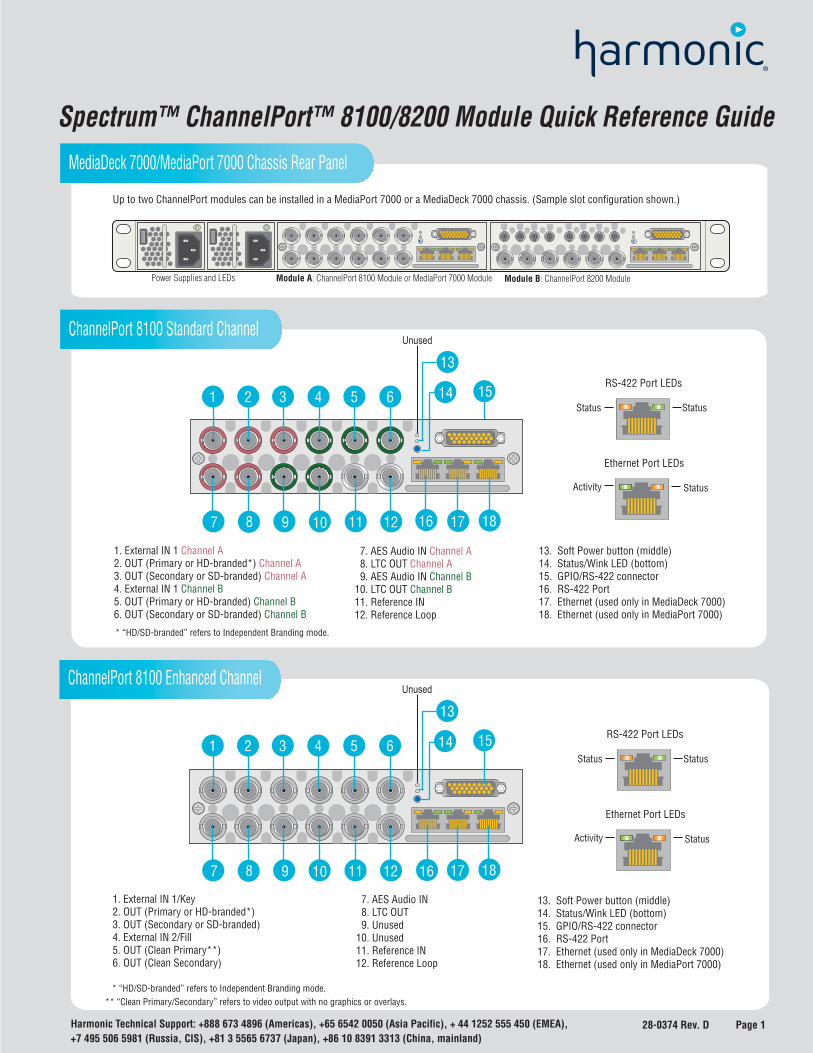
Spectrum™ ChannelPort™ 8100/8200 Module Quick Reference Guide
+7 495 506 5981 (Russia, CIS), +81 3 5565 6737 (Japan), +86 10 8391 3313 (China, mainland)Harmonic Technical Support: +888 673 4896 (Americas), +65 6542 0050 (Asia Pacific), + 44 1252 555 450 (EMEA),
16
4 5
Up to two ChannelPort modules can be installed in a MediaPort 7000 or a MediaDeck 7000 chassis. (Sample slot configuration shown.)
MediaDeck 7000/MediaPort 7000 Chassis Rear Panel
ChannelPort 8100 Standard Channel
ChannelPort 8100 Enhanced Channel
Ethernet Port LEDs
Activity Status
RS-422 Port LEDs
StatusStatus
13. Soft Power button (middle) 14. Status/Wink LED (bottom) 15. GPIO/RS-422 connector 16. RS-422 Port 17. Ethernet (used only in MediaDeck 7000) 18. Ethernet (used only in MediaPort 7000)
1. External IN 1 Channel A2. OUT (Primary or HD-branded*) Channel A3. OUT (Secondary or SD-branded) Channel A4. External IN 1 Channel B5. OUT (Primary or HD-branded) Channel B6. OUT (Secondary or SD-branded) Channel B
7. AES Audio IN Channel A 8. LTC OUT Channel A 9. AES Audio IN Channel B10. LTC OUT Channel B11. Reference IN12. Reference Loop
* “HD/SD-branded” refers to Independent Branding mode.
15
1
Unused
2 3 4 5 6
13
8 9 10 11 12
141
7 16 17 18
Unused
2 3 4 5 6
13
8 9 10 11 12
141
7
15
16 17 18
13. Soft Power button (middle) 14. Status/Wink LED (bottom) 15. GPIO/RS-422 connector 16. RS-422 Port 17. Ethernet (used only in MediaDeck 7000) 18. Ethernet (used only in MediaPort 7000)
1. External IN 1/Key 2. OUT (Primary or HD-branded*) 3. OUT (Secondary or SD-branded) 4. External IN 2/Fill 5. OUT (Clean Primary**) 6. OUT (Clean Secondary)
7. AES Audio IN 8. LTC OUT 9. Unused10. Unused11. Reference IN12. Reference Loop
* “HD/SD-branded” refers to Independent Branding mode.** “Clean Primary/Secondary” refers to video output with no graphics or overlays.
Power Supplies and LEDs Module A: ChannelPort 8100 Module or MediaPort 7000 Module Module B: ChannelPort 8200 Module
Ethernet Port LEDs
Activity Status
RS-422 Port LEDs
StatusStatus
28-0374 Rev. D Page 1
28-0374 Rev. D Page 2 +7 495 506 5981 (Russia, CIS), +81 3 5565 6737 (Japan), +86 10 8391 3313 (China, mainland)
Harmonic Technical Support: +888 673 4896 (Americas), +65 6542 0050 (Asia Pacific), + 44 1252 555 450 (EMEA),
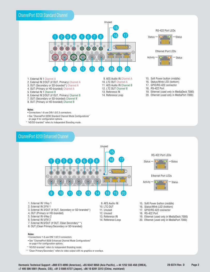
ChannelPort 8200 Standard Channel
Unused
15
16 171 2 3 4 5 6 7 8
9 10 11 12 13 14 18 19 20
15. Soft Power button (middle) 16. Status/Wink LED (bottom) 17. GPIO/RS-422 connector 18. RS-422 Port 19. Ethernet (used only in MediaDeck 7000) 20. Ethernet (used only in MediaPort 7000)
1. External IN 1 Channel A2. External IN 2/OUT (if OUT, Primary) Channel A3. OUT (Secondary or SD-branded*) Channel A4. OUT (Primary or HD-branded) Channel A5. External IN 1 Channel B6. External IN 2/OUT (if OUT, Primary) Channel B7. OUT (Secondary or SD-branded) Channel B8. OUT (Primary or HD-branded) Channel B
9. AES Audio IN Channel A10. LTC OUT Channel A11. AES Audio IN Channel B12. LTC OUT Channel B13. Reference IN14. Reference Loop
* “HD/SD-branded” refers to Independent Branding mode.
Ethernet Port LEDs
Activity Status
RS-422 Port LEDs
StatusStatus
ChannelPort 8200 Enhanced Channel
* “HD/SD-branded” refers to Independent Branding mode.** “Clean Primary/Secondary” refers to video output with no graphics or overlays.
Unused
15
16 171 2 3 4 5 6 7 8
9 10 11 12 13 14 18 19 20
15. Soft Power button (middle) 16. Status/Wink LED (bottom) 17. GPIO/RS-422 connector 18. RS-422 Port 19. Ethernet (used only in MediaDeck 7000) 20. Ethernet (used only in MediaPort 7000)
1. External IN 1/Key 12. External IN 2/Fill 13. External IN 3/OUT (if OUT, Secondary or SD-branded*)4. OUT (Primary or HD-branded)5. External IN 4/Key 26. External IN 5/Fill 27. External IN 6/OUT (if OUT, Clean Secondary**)8. OUT (Clean Primary/Secondary or SD-branded)
9. AES Audio IN10. LTC OUT11. Unused12. Unused13. Reference IN14. Reference Loop
Notes: • Connections 1-8 use DIN 1.0/2.3 connectors.• See “ChannelPort 8200 Enhanced Channel Mode Configurations” on page 4 for configuration options.
Ethernet Port LEDs
Activity Status
RS-422 Port LEDs
StatusStatus
Notes: • Connections 1-8 use DIN 1.0/2.3 connectors.• See “ChannelPort 8200 Standard Channel Mode Configurations” on page 4 for configuration options.
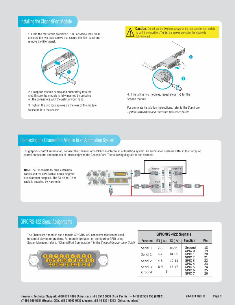
1. From the rear of the MediaPort 7000 or MediaDeck 7000,unscrew the two lock screws that secure the filler panel andremove the filler panel.
1
Caution: Do not use the two lock screws on the rear panel of the module to pull it into position. Tighten the screws only after the module is fully inserted.
4. If installing two modules, repeat steps 1-3 for thesecond module.
For complete installation instructions, refer to the SpectrumSystem Installation and Hardware Reference Guide.
3. Tighten the two lock screws on the rear of the moduleto secure it to the chassis.
2
3
2. Grasp the module handle and push firmly into the slot. Ensure the module is fully inserted by pressingon the connectors with the palm of your hand.
+7 495 506 5981 (Russia, CIS), +81 3 5565 6737 (Japan), +86 10 8391 3313 (China, mainland)Harmonic Technical Support: +888 673 4896 (Americas), +65 6542 0050 (Asia Pacific), + 44 1252 555 450 (EMEA),
Installing the ChannelPort Module
Note: The DB-9 male-to-male extensioncables and the GPIO cable in this diagramare customer supplied. The RJ-45-to-DB-9cable is supplied by Harmonic.
For graphics control automation, connect the ChannelPort GPIO connector to an automation system. All automation systems differ in their array of control connectors and methods of interfacing with the ChannelPort. The following diagram is one example.
Connecting the ChannelPort Module to an Automation System
Play 1
Graphics 1 Graphics 2
Play 2
422(3)
422(4)
422(1)
422(2)
GPIO/RS-422 Signal Assignments
9 8 7 6 5 4 18 17 16 15 13 12 11 10
26 25 24 23 22 21 20 19
13 214
Function RX (-/+) TX (-/+)
GPIO/RS-422 Signals Function Pin
Ground
Ground 18 Serial 0
2-3
GPIO 0 19 GPIO 1 20 Serial 1
GPIO 2 21 GPIO 3 22 Serial 2
GPIO 4 23 GPIO 5 24 Serial 3
GPIO 6 25 GPIO 7 26
8-9
10-11
16-17 1
6-7
4-5
14-15
12-13
The ChannelPort module has a femaie GPIO/RS-422 connector that can be usedto control players or graphics. For more information on configuring GPIO usingSystemManager, refer to “ChannelPort Configuration” in the SystemManager User Guide.
28-0374 Rev. D Page 3
+7 495 506 5981 (Russia, CIS), +81 3 5565 6737 (Japan), +86 10 8391 3313 (China, mainland)Harmonic Technical Support: +888 673 4896 (Americas), +65 6542 0050 (Asia Pacific), + 44 1252 555 450 (EMEA),
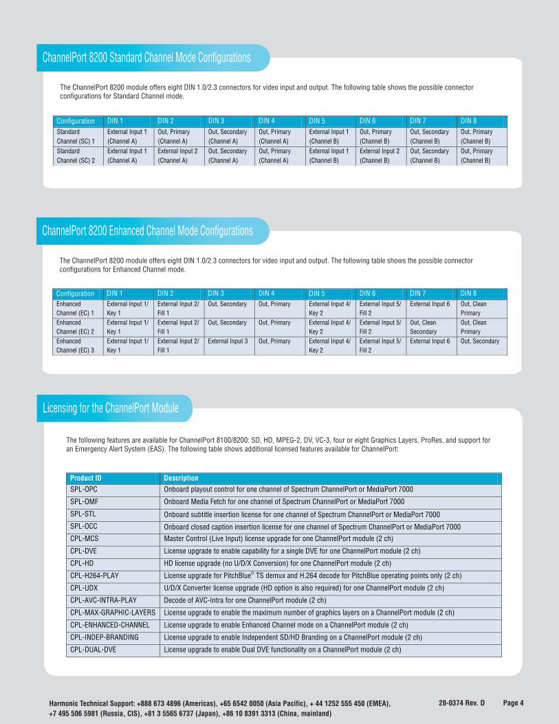
ChannelPort 8200 Standard Channel Mode Configurations
The following features are available for ChannelPort 8100/8200: SD, HD, MPEG-2, DV, VC-3, four or eight Graphics Layers, ProRes, and support for an Emergency Alert System (EAS). The following table shows additional licensed features available for ChannelPort:
Licensing for the ChannelPort Module
Product ID Description SPL-OPC Onboard playout control for one channel of Spectrum ChannelPort or MediaPort 7000
SPL-OMF Onboard Media Fetch for one channel of Spectrum ChannelPort or MediaPort 7000
SPL-STL Onboard subtitle insertion license for one channel of Spectrum ChannelPort or MediaPort 7000
SPL-OCC Onboard closed caption insertion license for one channel of Spectrum ChannelPort or MediaPort 7000
CPL-MCS Master Control (Live Input) license upgrade for one ChannelPort module (2 ch)
CPL-DVE License upgrade to enable capability for a single DVE for one ChannelPort module (2 ch)
CPL-HD HD license upgrade (no U/D/X Conversion) for one ChannelPort module (2 ch)
CPL-H264-PLAY License upgrade for PitchBlue® TS demux and H.264 decode for PitchBlue operating points only (2 ch)
CPL-UDX U/D/X Converter license upgrade (HD option is also required) for one ChannelPort module (2 ch)
CPL-AVC-INTRA-PLAY Decode of AVC-Intra for one ChannelPort module (2 ch)
CPL-MAX-GRAPHIC-LAYERS License upgrade to enable the maximum number of graphics layers on a ChannelPort module (2 ch)
CPL-ENHANCED-CHANNEL License upgrade to enable Enhanced Channel mode on a ChannelPort module (2 ch)
CPL-INDEP-BRANDING License upgrade to enable Independent SD/HD Branding on a ChannelPort module (2 ch)
CPL-DUAL-DVE License upgrade to enable Dual DVE functionality on a ChannelPort module (2 ch)
The ChannelPort 8200 module offers eight DIN 1.0/2.3 connectors for video input and output. The following table shows the possible connector configurations for Standard Channel mode.
28-0374 Rev. D Page 4
Configuration DIN 1 DIN 2 DIN 3 DIN 4 DIN 5 DIN 6 DIN 7 DIN 8 Standard Channel (SC) 1
External Input 1 (Channel A)
Out, Primary (Channel A)
Out, Secondary (Channel A)
Out, Primary (Channel A)
External Input 1 (Channel B)
Out, Primary (Channel B)
Out, Secondary (Channel B)
Out, Primary (Channel B)
Standard Channel (SC) 2
External Input 1 (Channel A)
External Input 2 (Channel A)
Out, Secondary (Channel A)
Out, Primary (Channel A)
External Input 1 (Channel B)
External Input 2 (Channel B)
Out, Secondary (Channel B)
Out, Primary (Channel B)
ChannelPort 8200 Enhanced Channel Mode Configurations
The ChannelPort 8200 module offers eight DIN 1.0/2.3 connectors for video input and output. The following table shows the possible connector configurations for Enhanced Channel mode.
Configuration DIN 1 DIN 2 DIN 3 DIN 4 DIN 5 DIN 6 DIN 7 DIN 8 Enhanced Channel (EC) 1
External Input 1/ Key 1
External Input 2/ Fill 1
Out, Secondary Out, Primary External Input 4/ Key 2
External Input 5/ Fill 2
External Input 6 Out, Clean Primary
Enhanced Channel (EC) 2
External Input 1/ Key 1
External Input 2/ Fill 1
Out, Secondary Out, Primary External Input 4/ Key 2
External Input 5/ Fill 2
Out, Clean Secondary
Out, Clean Primary
Enhanced Channel (EC) 3
External Input 1/ Key 1
External Input 2/ Fill 1
External Input 3 Out, Primary External Input 4/ Key 2
External Input 5/ Fill 2
External Input 6 Out, Secondary