Embed Size (px)
DESCRIPTION
NOTE When the device sends control commands and the push-button is pressed again, then the current one command transmission is interrupted to send new commands. Operational temperature 105 °C Parameter no. 8 – The percentage of a dimming step at automatic control. default value 1 STEP 1 Connect the device in accordance with the circuit diagram presented in Fig. 1. or Fig. 2. Switch on the mains voltage of 230V. In accordance with EU standards DICTIONARY: LNOSxS2S1 868 MHz Z-Wave Range 2.5 A
Citation preview
OPERATING MANUALUNIVERSAL DIMMER 500W
FGD211 v1.4.
ENG
Remotely controlled Dimmer of FIBARO system is designed to operate with or without neutral lead. It may be used as a switch in systems without neutral lead.
As the Dimmer it operates under the following loads: - conventional incandescent - halogen 230V - low voltage halogen 12V (with electronic transformers) - dimmable LED- when used with FGB001 it may operate with any dimmable load up to 500W
Moreover, as an electronic switch it may work with: - compact fluorescent lamps- LED bulbs - fluorescent lamps with electronic stabilisers and majority of conventional stabilisers - when used with FGB001 it may operate with any dimmable load up to 500W
*for loads other than resistive do not exceed 1.5A current
• Controlled by FIBARO system devices or any other Z-Wave controller. • Microprocessor control • Executive element: triac. • Soft start. • May operate in 3-way, 4-way systems • Memory of the last lighting level settings • The device may be operated by mono-stable and bi-stable push-buttons.
Specifications
Power supply
Output Power
In accordance with EU standards
Overcurrent protection
Circuit temperature limits
For installation in boxes
Radio protocol
Radio Frequency
Range
Dimensions (H x W x D)
230 V ±10% 50Hz
25-500 W (for resistive loads)
EN 55015 (noise) EN 60669-2-1 (operational safety)
2.5 A
Operational temperature105 °C
10 - 40 °C
Ø ≥ 50mm
Z-Wave
868 MHz
up to 50 m outdoorsup to 30 m indoors(depending on building materials)15 x 42 x 36 mm
Technical Information
DANGERDanger of electrocution! All works on the device may be performed only by a qualified and licensed electrician. Observe national regulations.
FIBARO is a wireless system, based on Z-Wave technology. FIBARO provides many advantages when compared to similar systems. In general, radio systems create a direct connection between the receiver and transmitter. But the radio signal is weakened by various obstacles located on its path (apartment walls, furniture, etc.) and in extreme cases it fails to transfer required data. The advantage of FIBARO system is that its devices apart from being transmitters and receivers of signals, they are also a signal "duplicators". When a direct connection path between the transmitter and the receiver can not be established, the connection may be achieved through other intermediate devices.
FIBARO is a bi-directional wireless system. It means that the signal is not only sent to the receivers but also the receivers send the confirmation of its reception. This operation confirms their status so to check whether they are active. Safety of the FIBARO system transmission is comparable to the safety of transmission in data bus wired systems.
FIBARO operates in the free band for data transmission at 868MHz frequency. Every FIBARO system has its own unique identification number (home ID). Therefore, it is possible to operate two or more independent systems in one building without any interference.
Although Z-Wave is quite new technology, it has already become recognizable and officially binding standard, similarly to Wi-Fi. Many manufacturers in various industries offer solutions based on Z-Wave technology, guaranteeing their compatibility. This means that the system is open and it may be extended in the future. Find more information at www.fibaro.com.
FIBARO generates a dynamic network structure. After FIBARO system is switched on, the location of its individual components is automatically updated in real-time through status confirmation signals received from devices operating in a "mesh" network.
The In-wall Universal Dimmer is hereinafter referred to as Dimmer. It is designed to turn on and dim lamps (see specificatios) using radio waves, controllers and push buttons directly connected to Dimmer. Dimmer automaticly recognizes connected load, is protected from overcurrent and short circut, works noiselessly and has soft start function witch allows soft brightening of connected load (in case of fluorescent lamps and other specific lamps i.e. with starter or some transformers of old type, it is possible only to turn on/off without possibility of dimming)
Danger of electrocution.
II Assembling the Dimmer
1. Before installation ensure that the voltage supply is disconnected.2. Connect the Dimmer according to the diagram below.3. Place all elements in the electrical box. 4. Arrange the antenna (tips are presented below diagrams of fig. 1 and 2)
I GENERAL INFORMATION ABOUT FIBARO SYSTEM
Note! The length of wires used to connect the control switch should not exceed 20m. For supplying power to the switch, the terminal marked with "L" may be also used; Controlling a phase other than "L" is also acceptable.
i
Note! It should be noted that the push-button connected to S1 terminal is an overriding push-button, it activates the basic functionality of the Dimmer (turning the light on/off, dimming) and starts the learning mode (Include / Exclude). The push-button connected to S2 terminal is an optional push-button and pushing it without changing the configuration parameters will not affect the status of the device.
i
Parameter no. 1 - Activate / deactivate functions ALL ON / ALL OFF. default value 255
Available configuration parameters:255 - ALL ON active, ALL OFF active.0 - ALL ON is not active ALL OFF is not active1 - ALL ON is not active ALL OFF active2 - ALL ON active ALL OFF is not active
Parameter no. 6 - Separation of association sending for group no. 1 (key no. 1) default value 0
Possible configuration parameters:
0 - Turning on and turning off device causes sending of commands to all associated devices in group no. 1.
1 - Turning off device causes sending of turning off command to all associated devices in group no. 1. Turning on device douse not causes sending of any command to all associated devices in group no. 1. Double click of key causes turning on all associated devices, dimmers are set to last remembered state.
2 - Turning off device causes sending of turning off command to all associated devices in group no. 1. Turning on device douse not causes sending of any command to all associated devices in group no. 1. Double click of key causes turning on all associated devices, dimmers are set to 100%.
NOTE: Correct work of parameter no. 6 needs to set parameter 15 on 1. It will allow to turn on double click - control of Dimmer / Roller Shutter.
Parameter no. 7 – Checking the device status before sending a control frame from the key No. 2 default value 1
Available configuration parameters:
0 - Device status is not checked.1 - Device status is checked.
Info: Key no. 2 is not represented by any physical device expect of devices on association list. This functionality prevents of lack of reaction on pressing key no. 2 through polling devices from asociation list one by one and checking thier actual states.
Parameter no. 8 – The percentage of a dimming step at automatic control. default value 1
Options for changing parameter 1-99
Parameter No. 9 - Time of manually moving the Dimmer between the extreme dimming values. default value 5
Options for changing parameter 1-255 (10ms – 2.5s)
Parameter no. 10 - Time of Automatic moving the Dimmer between the extreme dimming values. default value 1
Options for changing parameter 0-255 (0ms – 2.5s) 0 - this value disables the smooth change in light intensity
NOTE value 0 is required for inductive and capacitive devices unsuitable for dimming, (e.g. fluorescent lamps , motors etc.)
Parameter No. 11 - The percentage of a dimming step at manual control default value 1
Options for changing parameter 1-99
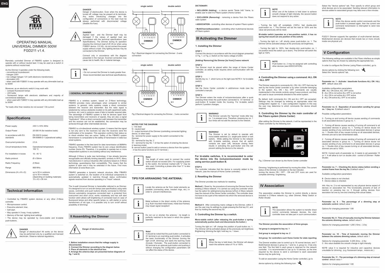
NOTES FOR THE DIAGRAM:L - live leadN - neutral leadO - output terminal of the Dimmer (controlling connected lighting device, or other load)Sx - terminal for power supply to the switch connected to the Dimmer; S2 - terminal for key No. 2S1 - terminal for key No. 1 (it has the option of entering the device in learning mode)B- service button (used to add or remove a device from the system) - it has the same functions as S1 terminal )
Locate the antenna as far from metal elements as possible (connecting wires, bracket rings, etc.) in order to prevent interferences. iMetal surfaces in the direct vicinity of the antenna (e.g. flush mounted metal boxes, metal door frames) may impair signal reception! iDo not cut or shorten the antenna - its length is perfectly matched to the band in which the system operatesi
TIPS FOR ARRANGING THE ANTENNA:
DICTIONARY: • INCLUSION (Adding) - a device sends "Node Info" frame, to enable user to add it to Fibaro system (Home Center)
• EXCLUSION (Removing) - removing a device from the Fibaro radio system
• ASSOCIATION - controlling other devices of system Fibaro system
• MultiChannelAssociation - controlling other multichannel devices of Fibaro system
III Activating the Dimmer
1. Installing the Dimmer
STEP 1 Connect the device in accordance with the circuit diagram presented in Fig. 1. or Fig. 2. Switch on the mains voltage of 230V.
[Adding/ Removing] the Dimmer [to/ from] Z-wave network
STEP 2 The Dimmer must be placed within the range of Home Center controller, as adding mode requires direct communication with the controller. STEP 3 Identify key no. 1. which turns on the light (see NOTE II for bi-stable switch)
STEP 4 Set the Home Center controller in add/remove mode (see the controller's manual)
STEP 5 The Dimmer enters the mode of inclusion/exclusion after a quick pressing three times the push-button connected to S1 terminal or push-button B located inside the housing. For bi-stable switch perform 3 position changes.
WARNING! The Dimmer cancels the "learning" mode after key no. 1 is pressed once. Therefore, pressing key no. 1 four times will not add the devices to the network.i
WARNING! The Dimmer is set by default to operate with mono-stable switches (i.e. single-pole switch or bell switch). While adding the Dimmer to the network with bi-stable switches, ensure that all switch contacts are open (off), because closing them results in activating the push-button and this will prevent adding the device to the network.
i
For bi-stable switches, it is recommended to enter the device into the inclusion/exclusion mode by using service push-button B.
STEP 6 The controller indicates that the device is correctly added to the network, (see the manual of Home Center controller).
2. Resetting the Dimmer
The Dimmer provides two methods for resetting.
Method I : Reset by the procedure of removing the Dimmer from the existing Z-Wave network. It is carried out using the controller which has the option for adding/removing devices to/from Z-Wave network (see the manual of the Home Center controller). The controller does not have to be a part of the network into which the removed device is included.
Method II : After connecting mains voltage to the Dimmer, within 5 sec the user may its settings by single pressing the first key S1, and then by holding the second key S2.
3. Controlling the Dimmer by a switch.
Mono-stable switch (after releasing the push-button a spring automatically pushes back and disconnects the button )
Turning the light on / off: change the position of push-button no. 1. The Dimmer will be activated always at the previously set brightness.Brightening/ dimming the light: hold key no. 1 down.
- Turning the light off completely (100%): fast double-click push-button no. 1. The Dimmer will set the load at 100% and the value set previously will be reset.
Bi-stable switch (operates as a two-position switch, it has no spring that would set one position of the switch)
- Turning the light on / off: shortly press push-button no. 1. The Dimmer will be activated always at the previously set brightness.
- Turning the light to 100%: fast double-click push-button no. 1 (re-position twice the switch up or down). The Dimmer will switch the light at 100%
4. Controlling the Dimmer using a command: ALL ON / ALL OFF
The Dimmer responds to commands ALL ON / ALL OFF that may be sent by the Home Center controller or by other controller belonging to the system. ALL ON / ALL OFF commands are usually implemented in the remote controls using Z-wave protocol, and they are used to issue commands directed to the entire system.
By default, both commands ALL ON and ALL OFF are accepted. Settings may be changed by entering an appropriate value into configuration register no. 1 (see configuration register) In this way the user may determine to which commands the device should respond.
5. Controlling the Dimmer by the main controller of the Fibaro system (Home Center)
After adding the Dimmer to the network, it will be represented in the Fibaro controller by the following icon:
Fig. 3 Dimmer icon shown by the Home Center controller
Dimming / brightening is performed by moving the slider. The current status of the Dimmer is indicated on the bar indicator. turning the device ON / OFF - ON and OFF icons are used for complete dimming / brightening
The association enables the Dimmer to control directly a device included in Z-Wave network e.g. other Dimmer, Relay Switch or Roller Shutter.
The Dimmer provides the association of three groups.
1st group is assigned to key no. 1
2nd group is assigned to key no. 2
3rd group for controllers such Home Center for state reporting
The Dimmer enables user to control up to 16 normal devices, and 7 MultiChannel devices in group no. 1 and no. 2, group no. 3 has only one field. The first field in each group is reserved for the network controller. It is recommended to use up to 10 devices, as the time required by the device to send a command to each associated device may be quite long.
To add an association (using the Home Center controller), go to
device options by clicking the following icon:
IV Association
NOTE The association allows the system to transfer direct control commands between devices, the main controller does not take part in such communication. i
Select the "device options" tab. Then specify to which group and what devices are to be associated. Sending relevant information to devices added to associated groups may take even a few minutes.
NOTEWhen the device sends control commands and the push-button is pressed again, then the current one command transmission is interrupted to send new commands.
iFGD211 Dimmer supports the operation of multi-channel devices. Multichannel devices are devices that include two or more circuits inside one physical unit.
The following settings are available in the Fibaro interface as simple options that may be chosen by selecting the appropriate box.
In order to configure the Dimmer (using Fibaro controller), go to
device options by clicking the following icon: Select the "device options" tab.
V Configuration
DANGERDanger of electrocution. Even when the device is turned off, voltage may be present at its terminals. Any works introducing changes into the configuration of connections or the load must be always performed with disconnected voltage (disable the fuse).
TIPS• Do not connect the Dimmer to loads greater than those recommended (see technical specifications).
DANGERApplied load and the Dimmer itself may be damaged if the values of applied load are inconsistent with the technical specifications (see Specifications). The Dimmer during its operation requires the minimum load of 25 VA (or when using FGB001 device - 0.5 VA) - do not connect the power supply without a load. Only lighting devices may be connected to the Dimmer.
Connect only in accordance with the diagram presented in the manual. Incorrect connection may cause risk to health, life or material damage.
i
single switch double switch
single switch double switch
L N O Sx S2 S1
DIMMER DIMMER
LN
L N O Sx S2 S1
LN
B B
Fig.1 Electrical diagram for connecting the Dimmer - 2-wire connection
Fig.2 Electrical diagram for connecting the Dimmer - 3-wire connection
L N O Sx S2 S1
DIMMER
LN
B
DIMMER
L N O Sx S2 S1
LN
B
NOTEWhen the key is held down, the Dimmer will always reach the extreme value of 1% or 100%. i
NOTEWhen one of the buttons is held down to achieve smooth change of light intensity, the second button does not respond to any action.
i
NOTEPush-button no. 2 may be assigned with controlling other devices (see ASSOCIATION)i
Parameter No. 12 - Maximum Dimmer level control default value 99
Options for changing parameter 2-99
Parameter No. 13 - Minimum Dimmer level control default value 2
Options for changing parameter 1-98
NOTE The maximum level may not be lower than the minimum level.
Recommended values of parameters 12 and 13 (max and min level) for controlling the devices are as follows:
• AC motors [min 60%, max 99%]• fluorescent lamps, fluorescent tubes, LED [min 98%, max 99%] [parameter 10 set to 0]
Parameter no. 14 - Switch type connector, you may choose between mono-stable and bi-stable switches. default value 0
Options for changing parameter:
0 - mono-stable switch1 - bi-stable switch
Parameter no. 15 – Double click option (set lightning at 100%) default value 1
Available configuration parameters:
0 Double click disabled1 Double click enabled
Parameter no. 16 - Saving the state of the device after a power failure. The Dimmer will return to the last position before power failure. default value 1 Options for changing parameter:
0 - the Dimmer does not save the state after a power failure, it returns to "off" position1 - the Dimmer saves its state before power failure
Parameter No. 17 - the function of 3 - way switch, provides the option to double key no. 1. The Dimmer may control two bi-stable push-buttons or an infinite number of mono-stable push-buttons. default value 0
Options for changing parameter 0-1
0 - the function of 3-way switch is disabled1 - the function of 3-way switch is enabled
Parameter no. 18 - The function of synchronizing the light level for associated devices. The Dimmer communicates the position to the associated device. default value 0
Options for changing parameter 0-1
0 - function disabled1 - function enabled
Parameter no. 19 - This function allows user to change [on / off] bi-stable keys (parameter no. 14). default value 0
Available configuration parameters:
0 [On / Off] changes key status.1 ON is active after closing switch contacts. Off is active after opening switch contacts.
VI Additional Functionality
Operating alarm data frames
Fibaro system allows user to set response of devices to alarm situations (response to data-frames ALARM_REPORT and SENSOR_ALARM_REPORT) Fibaro Dimmer responds to the following types of alarms:
• General Purpose Alarm - GENERAL PURPOSE ALARM [0x00]• Smoke Alarm - ALARM CO2 [0x02], ALARM CO [0x01], ALARM SMOKE [0x03]• Water Flooding Alarm - ALARM WATER [0x05]• Temperature Alarm - ALARM HEAT [0x04]
Alarm data-frames are sent by devices that are system sensors (e.g., flood sensors, smoke detectors, motion detectors, etc.).
The device may respond in the following manner to received data-frames (settings are configured in configuration parameters, see section V Configuration ):
• 0 - DEACTIVATION - the device does not respond to alarm data frames• 1 - ALARM ON - the device turns on after detecting an alarm• 2 - ALARM OFF - the device turns off after detecting an alarm• 3 - ALARM FLASHING - the device periodically changes its status to the opposite when it detects an alarm (lights on/off alternately)
IX GUARANTEE
1. The Guarantee is provided by FIBAR GROUP Sp. z o.o. (hereinafter "Manufacturer"), based in Poznan, ul. Lotnicza 1; 60-421 Poznan, entered in the register of the National Court Register kept by the District Court in Poznań, VIII Economic Department of the National Court Register, no. 370151, NIP 7811858097, REGON: 301595664.
2. The Manufacturer is responsible for equipment malfunction resulting from physical defects (manufacturing or material) of the Device for 12 months from the date of its purchasing.
3. The guarantee is valid exclusively in Europe.
4. During the Guarantee period, the Manufacturer shall remove any defects, free of charge, by repairing or replacing (at the sole discretion of the Manufacturer) any defective components of the Device with new or regenerated components, that are free of defects. When the repair impossible, the Manufacturer reserves the right to replace the device with a new or regenerated one, which shall be free of any defects and its condition shall not be worse than the original device owned by the Customer.
5. In special cases, when the device cannot be replaced with the device of the same type (e.g. the device is no longer available in the commercial offer), the Manufacturer may replace it with a different device having technical parameters similar to the faulty one. Such activity shall be considered as fulfilling the obligations of the Manufacturer. The Manufacturer shall not refund money paid for the device.
6. The holder of a valid guarantee shall submit a guarantee claim through the guarantee service. Remember: before you submit a guarantee claim, contact or technical support using telephone or e-mail. More than 50% of operational problems is resolved remotely, saving time and money spent to initiating guarantee procedure. If remote support is insufficient, the Customer shall fill the guarantee claim form (using our website - www.fibargroup.com) in order to obtain claim authorization.When the guarantee claim form is submitted correctly, the Customer shall receive the claim confirmation with an unique number (Return Merchandise Authorization -RMA).
7. The claim may be also submitted by telephone. In this case, the call is recorded and the Customer shall be informed about it by a consultant before submitting he claim. Immediately after submitting the claim, the consultant shall provide the Customer with the claim number (RMA-number).
8. When the guarantee claim form is submitted correctly, a representative of the Authorised Guarantee Service (hereinafter as "AGS") shall contact the Customer to agree the date and place of site visit, during which the technicians will examine the operation of the device in the presence of the customer.
9. Defects revealed within the guarantee period shall be removed not later than 30 days from the date of delivering the Device to AGS. The guarantee period shall be extended by the time in which the Device was kept by AGS.
10. The faulty device shall be provided by the Customer with complete standard equipment and documents proving its purchase.
11. Parts replaced under the guarantee are the property of the Manufacturer. The guarantee for all parts replaced in the guarantee process shall be equal to the guarantee period of the original device. The guarantee period of the replaced part shall not be extended.
12. Travel expenses or costs of delivering the faulty device shall be borne by the Manufacturer. For unjustified service calls, the Service may charge the Customer with travel expenses and handling costs related to the case.
13. AGS shall not accept a complaint claim only when: • the Device was misused or the manual was not observed,• the Device was provided by the Customer incomplete, without accessories or nameplate, • it was determined that the fault was caused by other reasons than a material or manufacturing defect of the Device • the guarantee document is not valid or there is no proof of purchase,
14. The Manufacturer shall not be liable for damages to property caused by defective device. The Manufacturer shall not be liable for indirect, incidental, special, consequential or punitive damages, or for any damages, including, inter alia, loss of profits, savings, data, loss of benefits, claims by third parties and any property damage or personal injuries arising from or related to the use of the Device.
15. The guarantee shall not cover:• mechanical damages (cracks, fractures, cuts, abrasions, physical deformations caused by impact, falling or dropping the device or other object, improper use or not observing the operating manual);• damages resulting from external causes, e.g.: flood, storm, fire, lightning, natural disasters, earthquakes, war, civil disturbance, force majeure, unforeseen accidents, theft, water damage, liquid leakage, battery spill, weather conditions, sunlight, sand, moisture, high or low temperature, air pollution;• damages caused by malfunctioning software, attack of a computer virus, or by failure to update the software as recommended by the Manufacturer;• damages resulting from: surges in the power and/or telecommuni-cation network, improper connection to the grid in a manner inconsistent with the operating manual, or from connecting other devices not recommended by the Manufacturer.• damages caused by operating or storing the device in extremely adverse conditions, i.e. high humidity, dust, too low (freezing) or too high ambient temperature. Detailed permissible conditions for operating the Device are defined in the operating manual;
• damages caused by using accessories not recommended by the Manufacturer• damages caused by faulty electrical installation of the Customer, including the use of incorrect fuses;• damages caused by Customer's failure to provide maintenance and servicing activities defined in the operating manual;• damages resulting from the use of spurious spare parts or accessories improper for given model, repairing and introducing alterations by unauthorized persons;• defects caused by operating faulty Device or accessories.
16. The scope of the guarantee repairs shall not include periodic maintenance and inspections, in particular cleaning, adjustments, operational checks, correction of errors or parameter programming and other activities that should be performed by the user (Buyer). The guarantee shall not cover natural wear and tear of the Device and its components listed in the operating manual and in technical documentation as such elements have a defined operational life.
17. If a defect is not covered by the guarantee, the Manufacturer reserves the right to remove such defect at its sole discretion, repairing the damaged or destroyed parts or providing components necessary for repair or replacement.
18. This guarantee shall not exclude, limit or suspend the Customer rights when the provided product is inconsistent with the purchase agreement.
This Device may be used with all devices certified with Z-Wave certificate and should be compatible with such devices produced by other manufacturers. Any device compatible with Z-Wave may be added to Fibaro system.
i
FIBARGROUP FIBAROIn case of any technical questions contact customer service centre in your country.
www.fibargroup.com
VII Operating the Dimmer
The Dimmer may be operated using the following control elements:
− any controller compatible with the system (e.g. Home Center controller) − a mobile phone (e.g. iPhone and phones from other manufacturers with appropriate software)− devices of tablet type (such as iPad)− PC, using a web browser− via push-buttons connected to outputs S1 and S2 − using service button B, located inside the housing (activates S1 input)
100% 100%
max 70
min 20
0% 0%
real scalescale available to the user
Parameter no. 30 - Alarm of any type (general alarm, water flooding alarm, smoke alarm: CO, CO2, temperature alarm)default value 3 ALARM FLASHING
0 - DEACTIVATION - the device does not respond to alarm data frames1 - ALARM DIMMER ON - the device turns on after detecting an alarm2 - ALARM DIMMER OFF - the device turns off after detecting an alarm3 - ALARM FLASHING the device periodically changes its status to the opposite, when it detects an alarm within 10 min.
Parameter no. 39 - Active flashing alarm time
default value 600Available configuration parameters: [1-65535][ms]
ADVANCED FUNCTIONParameter No. 20 - The function enabling the change of control impulse length. default value 110
Options for changing parameter 100-170
This function will enable decreasing the minimum level of the Dimmer by extending the control impulse. By changing the minimum level, the user may completely dim LED bulbs. Not all LED bulbs available on the market have the dimming option.
WARNING!Wrong setting of the function may cause incorrect operation of the Dimmer.
∆t 100 110 170
The device does not respond to a pre-programmed transmitter:
• Make sure that the maximum range is not exceeded and the signal path is not obstructed by metal surfaces such as metal cabinets, etc. • Make sure the device is not in the programming mode, or repeat the programming process.
VIII Procedures for malfunctions