Embed Size (px)
Citation preview
Dept of Mechanical Engineering and Mechanics, Drexel University
Fundamentals of Computer Aided Design
Dimensions in Engineering Drawings
MEM 201
Dept of Mechanical Engineering and Mechanics, Drexel University
Today’s Learning Objectives…
• What are dimensions.
• Fundamental Rules of Dimensioning.
• Guidelines for good dimensioning in engineering drawings.
• Dimensioning in AutoCAD.
Dept of Mechanical Engineering and Mechanics, Drexel University
Dimensions
• A dimension is for size and position (of the designed/modeled shape).
• A DIMENSION is a numerical value expressed in appropriate units of measurement and used to define the size, location, orientation, form or other geometric characteristics of a part.
• A method of communication to machinists in the Production facility.
• Different kinds:– Linear– Aligned– Angular– Radius/Diameter– Reference
Dept of Mechanical Engineering and Mechanics, Drexel University
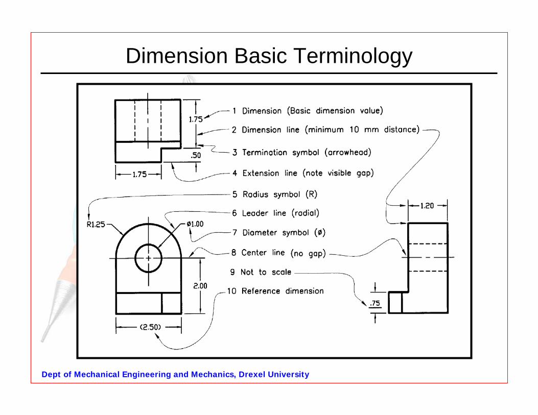
Dimension Basic Terminology
Dept of Mechanical Engineering and Mechanics, Drexel University
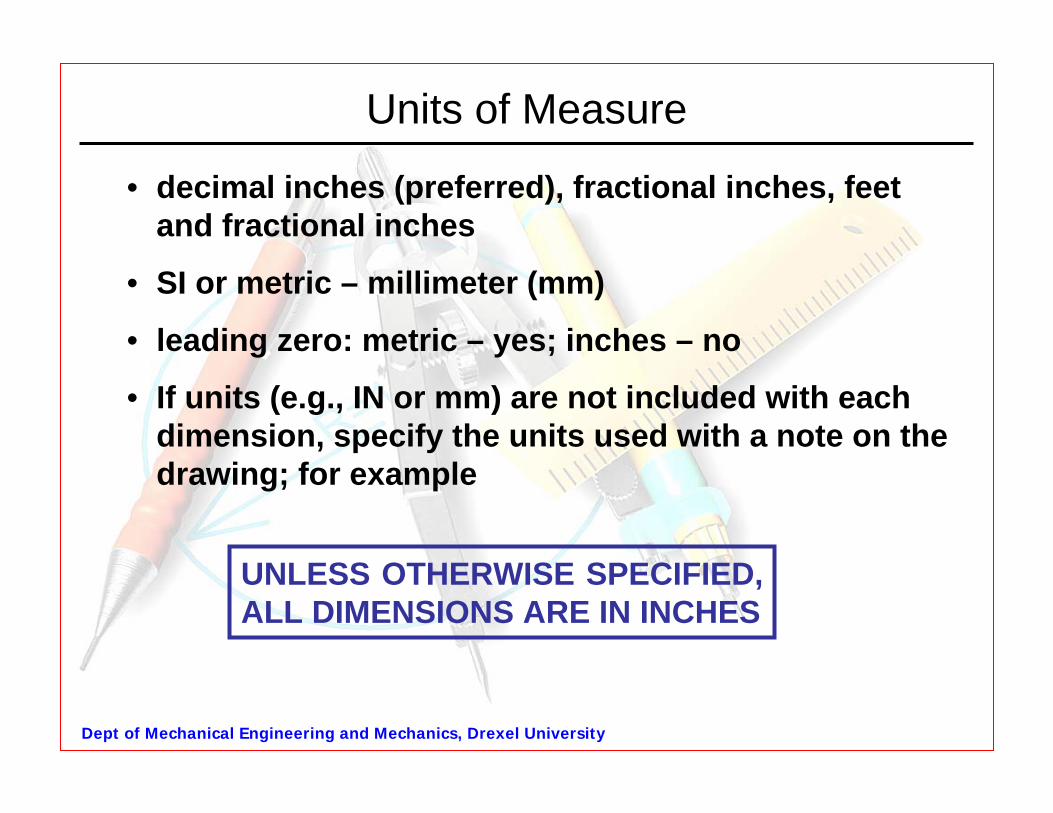
Units of Measure
• decimal inches (preferred), fractional inches, feet and fractional inches
• SI or metric – millimeter (mm)
• leading zero: metric – yes; inches – no
• If units (e.g., IN or mm) are not included with each dimension, specify the units used with a note on the drawing; for example
UNLESS OTHERWISE SPECIFIED, ALL DIMENSIONS ARE IN INCHES
Dept of Mechanical Engineering and Mechanics, Drexel University
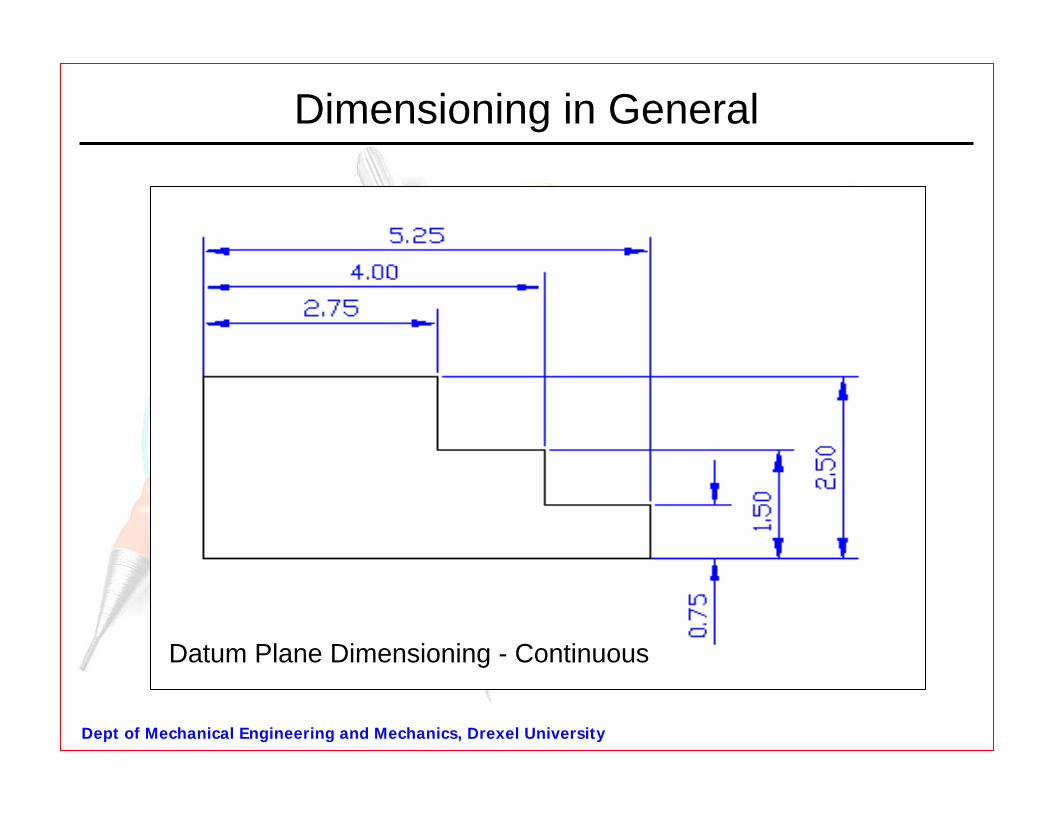
Dimensioning in General
Datum Plane Dimensioning - Continuous
Dept of Mechanical Engineering and Mechanics, Drexel University
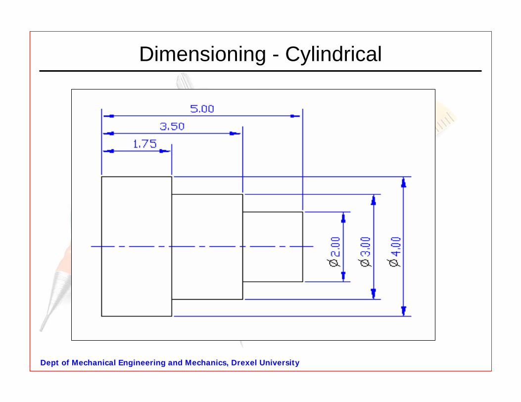
Dimensioning - Cylindrical
Dept of Mechanical Engineering and Mechanics, Drexel University
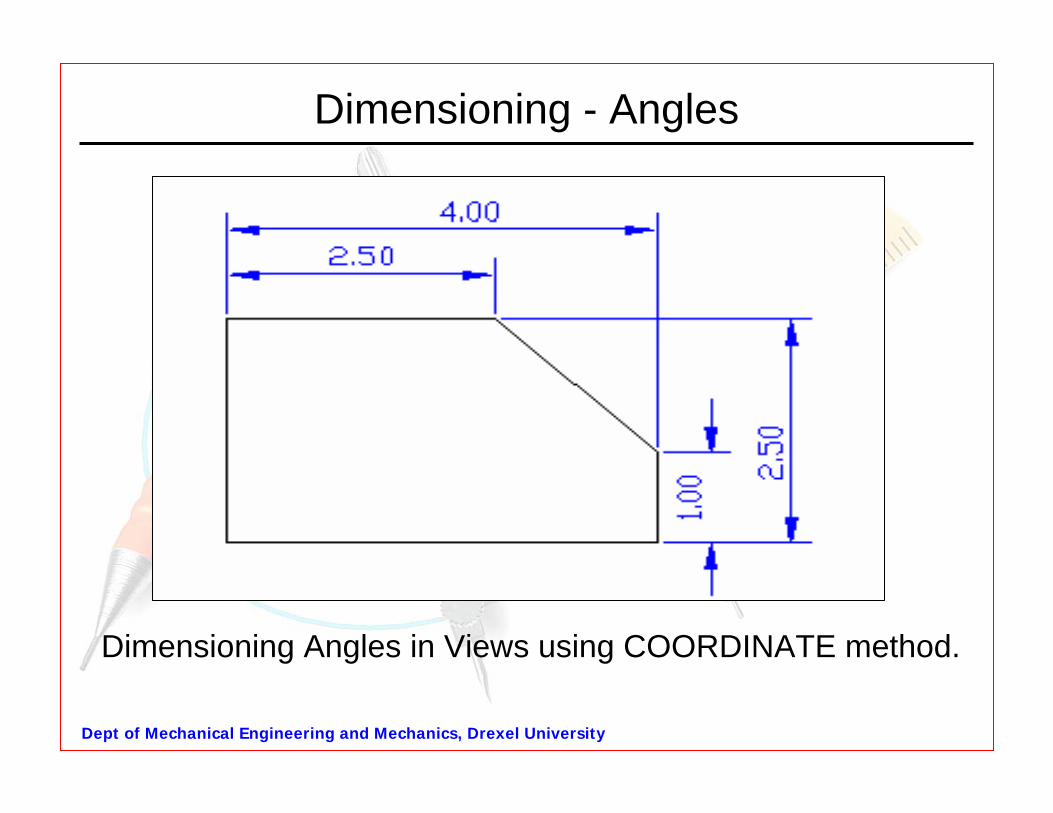
Dimensioning - Angles
Dimensioning Angles in Views using COORDINATE method.
Dept of Mechanical Engineering and Mechanics, Drexel University
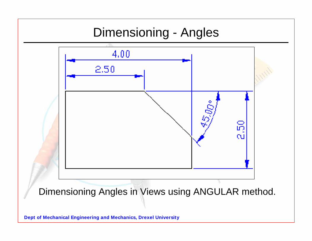
Dimensioning - Angles
Dimensioning Angles in Views using ANGULAR method.
Dept of Mechanical Engineering and Mechanics, Drexel University
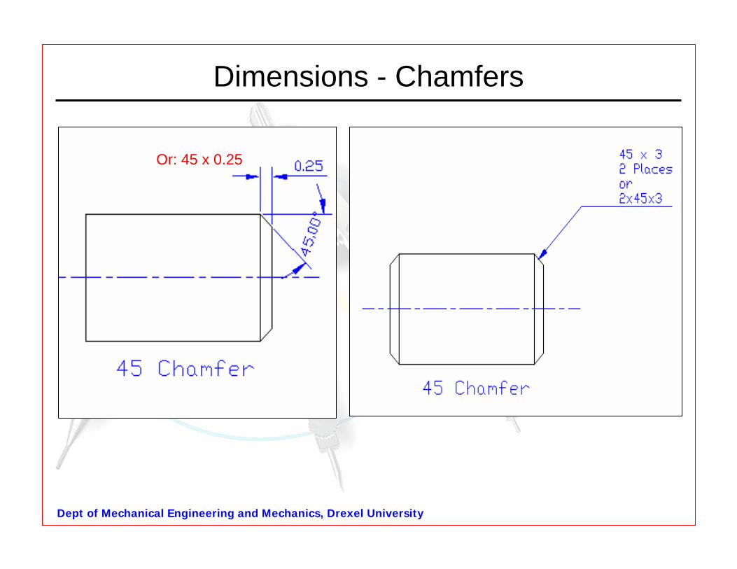
Dimensions - Chamfers
Or: 45 x 0.25
Dept of Mechanical Engineering and Mechanics, Drexel University
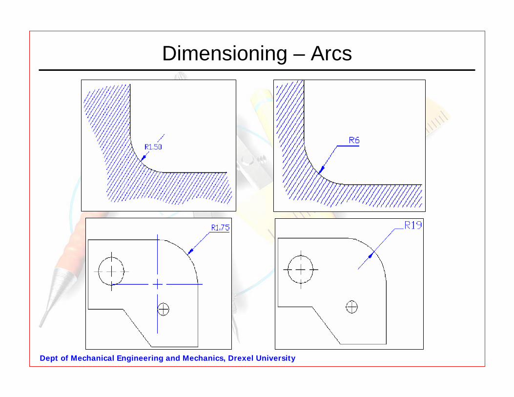
Dimensioning – Arcs
Dept of Mechanical Engineering and Mechanics, Drexel University
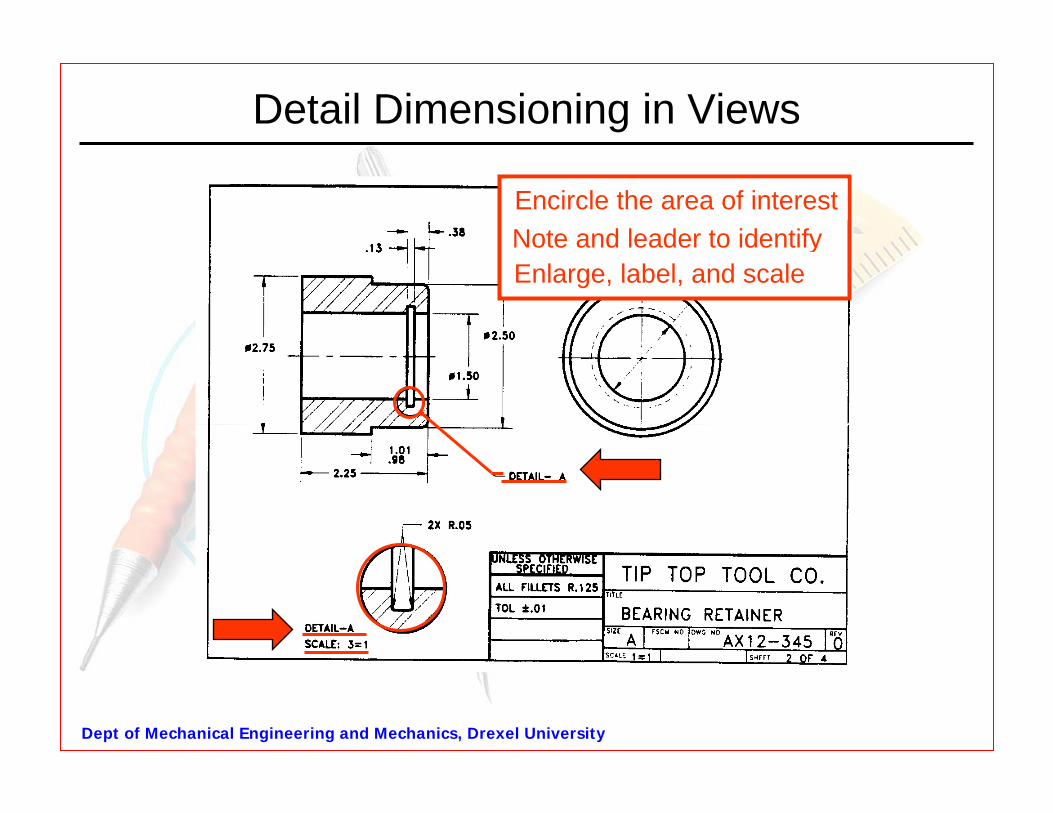
Detail Dimensioning in Views
Encircle the area of interestNote and leader to identify Enlarge, label, and scale
Dept of Mechanical Engineering and Mechanics, Drexel University
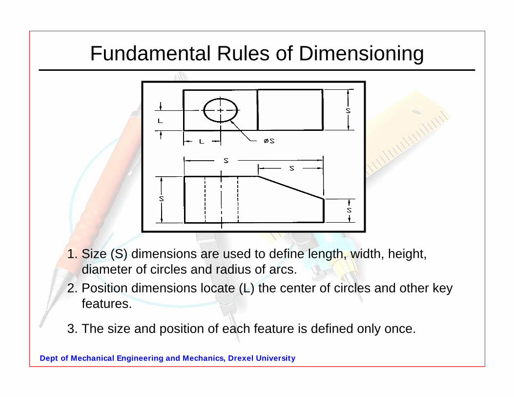
Fundamental Rules of Dimensioning
1. Size (S) dimensions are used to define length, width, height,diameter of circles and radius of arcs.
2. Position dimensions locate (L) the center of circles and other key features.
3. The size and position of each feature is defined only once.
Dept of Mechanical Engineering and Mechanics, Drexel University
Fundamental Rules of Dimensioning4. Dimension the feature in a view where its characteristic shape is shown.
5. English parts are dimensioned in inches with decimals, not fractions.
6. Metric parts are dimensioned in mm w/ decimals.
7. Units are omitted from the dimension numbers since they are normally understood to be in millimeters or inches.
8. Always leave at least 3/8 in. (10 mm) between the object and the first row of dimensions. Successive rows of dimensions should be equal and at least 0.25 in. (6 mm) apart.
Dept of Mechanical Engineering and Mechanics, Drexel University
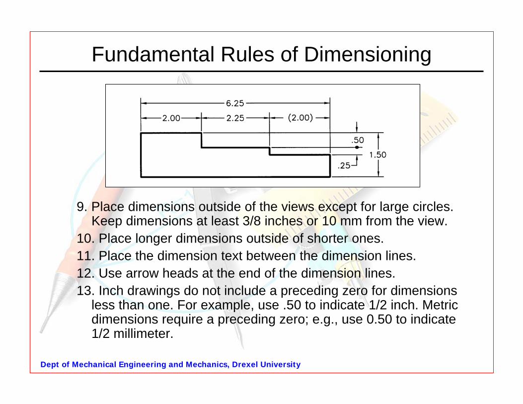
Fundamental Rules of Dimensioning
9. Place dimensions outside of the views except for large circles. Keep dimensions at least 3/8 inches or 10 mm from the view.
10. Place longer dimensions outside of shorter ones. 11. Place the dimension text between the dimension lines. 12. Use arrow heads at the end of the dimension lines. 13. Inch drawings do not include a preceding zero for dimensions
less than one. For example, use .50 to indicate 1/2 inch. Metricdimensions require a preceding zero; e.g., use 0.50 to indicate 1/2 millimeter.
Dept of Mechanical Engineering and Mechanics, Drexel University
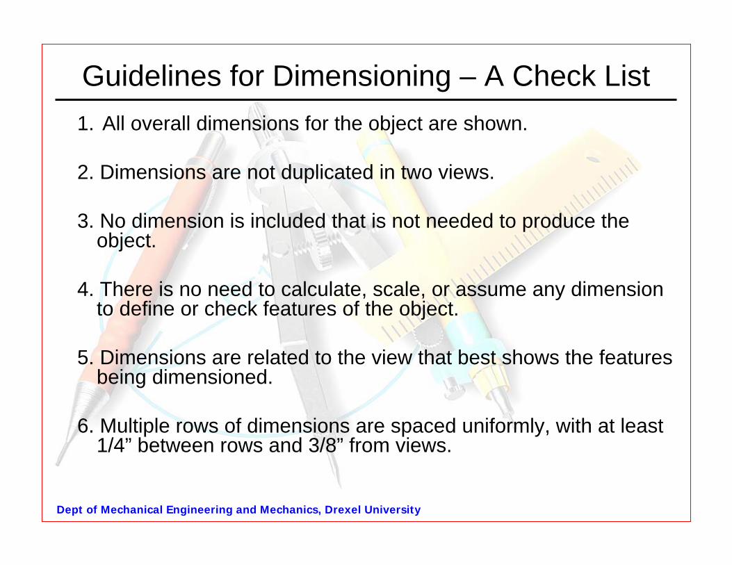
Guidelines for Dimensioning – A Check List1. All overall dimensions for the object are shown.
2. Dimensions are not duplicated in two views.
3. No dimension is included that is not needed to produce the object.
4. There is no need to calculate, scale, or assume any dimensionto define or check features of the object.
5. Dimensions are related to the view that best shows the features being dimensioned.
6. Multiple rows of dimensions are spaced uniformly, with at least 1/4” between rows and 3/8” from views.
Dept of Mechanical Engineering and Mechanics, Drexel University
Guidelines for Dimensioning
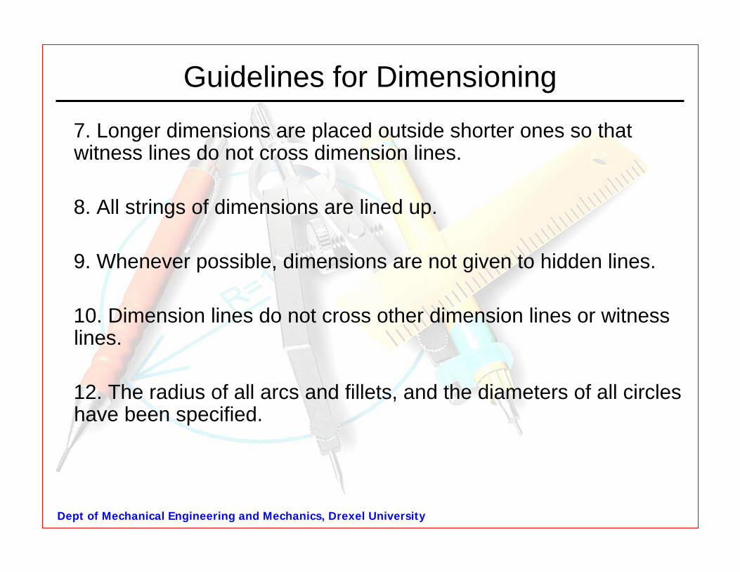
7. Longer dimensions are placed outside shorter ones so that witness lines do not cross dimension lines.
8. All strings of dimensions are lined up.
9. Whenever possible, dimensions are not given to hidden lines.
10. Dimension lines do not cross other dimension lines or witness lines.
12. The radius of all arcs and fillets, and the diameters of all circles have been specified.
Dept of Mechanical Engineering and Mechanics, Drexel University
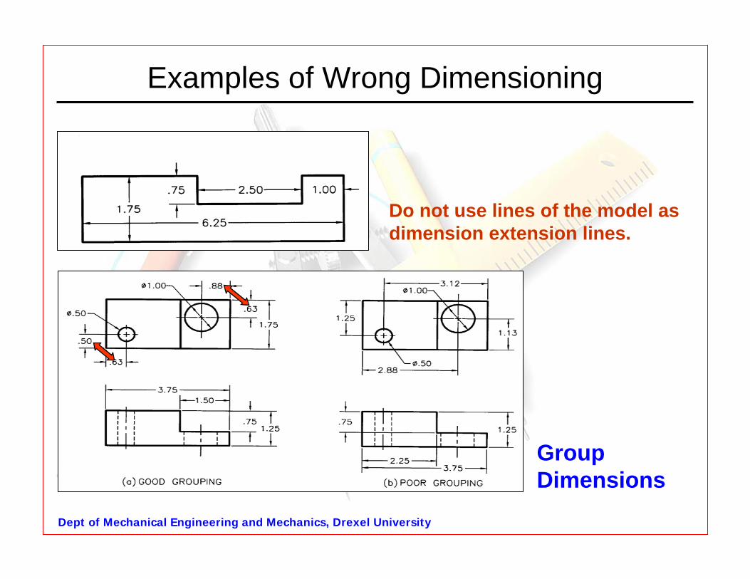
Examples of Wrong Dimensioning
Do not use lines of the model as dimension extension lines.
Group Dimensions
Dept of Mechanical Engineering and Mechanics, Drexel University
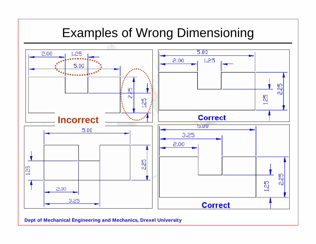
Examples of Wrong Dimensioning
Incorrect
Dept of Mechanical Engineering and Mechanics, Drexel University
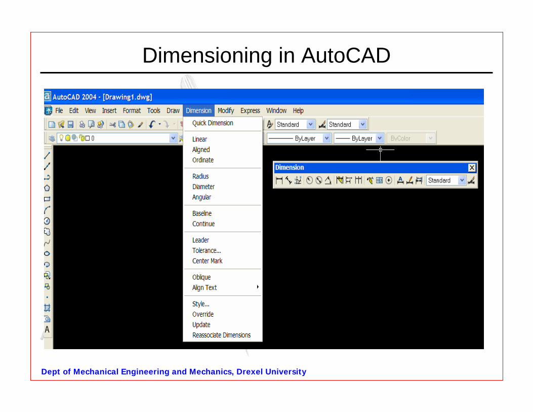
Dimensioning in AutoCAD
Dept of Mechanical Engineering and Mechanics, Drexel University
QUESTIONS?