Embed Size (px)
Citation preview

Digital vs. Analogue Control Systems
Presented at the 2011 Annual Meeting of the American College of Medical Physics, Chattanooga, TN, May 1, 2011
Ivan A. Brezovich, PhD, Dept. of Rad Onc, Univ of Alabama at Birmingham
Disclosure: Research supported in part by Varian Medical Systems
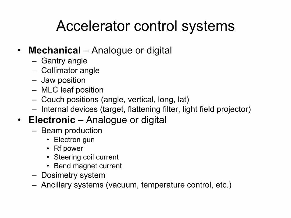
Accelerator control systems•
Mechanical
–
Analogue or digital
–
Gantry angle –
Collimator angle–
Jaw position–
MLC leaf position–
Couch positions (angle, vertical, long, lat)–
Internal devices (target, flattening filter, light field projector)•
Electronic
–
Analogue or digital
–
Beam production•
Electron gun•
Rf power•
Steering coil current•
Bend magnet current–
Dosimetry system–
Ancillary systems (vacuum, temperature control, etc.)
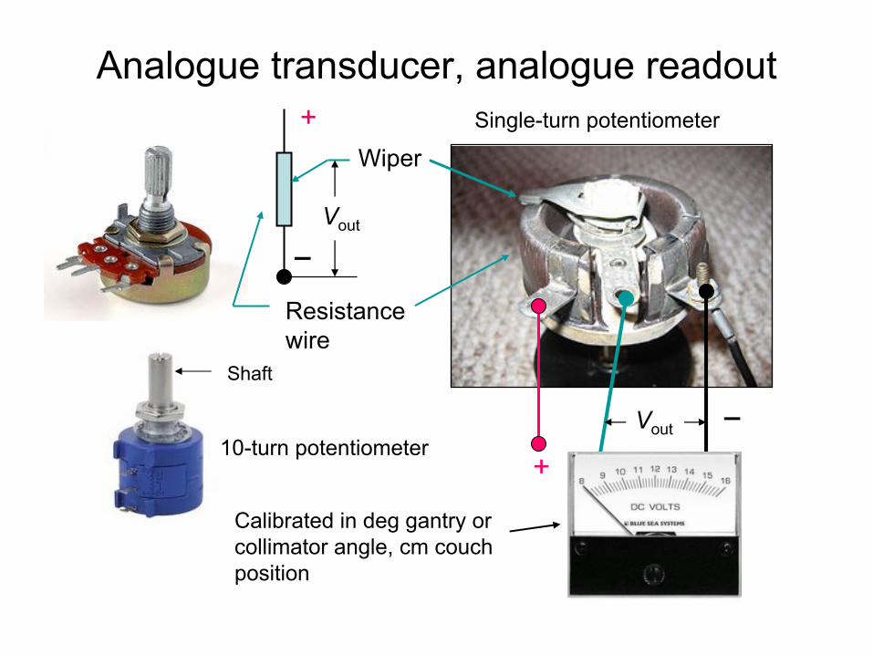
Analogue transducer, analogue readout
10-turn potentiometer+
Calibrated in deg gantry or collimator angle, cm couch position
−
Wiper
Resistance wire
−
+
Vout
Vout
Single-turn potentiometer
Shaft
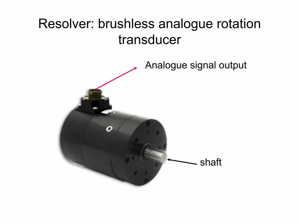
Resolver: brushless analogue rotation transducer
shaft
Analogue signal output
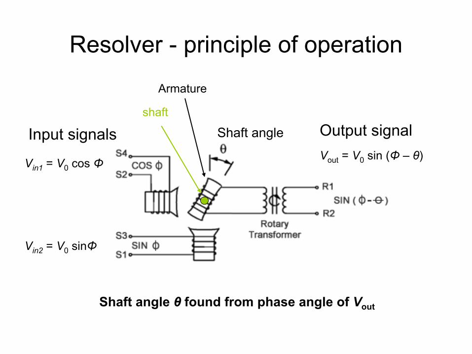
Resolver -
principle of operation
Input signals
Vin1
= V0
cos Φ
Vin2
= V0
sinΦ
Output signalVout
= V0
sin (Φ
–
θ)
Armature
Shaft angle
Shaft angle θ
found from phase angle of Vout
shaft
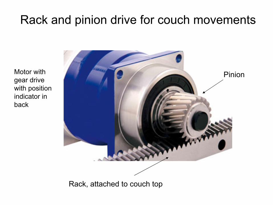
Rack, attached to couch top
Pinion
Rack and pinion drive for couch movements
Motor with gear drive with position indicator in back
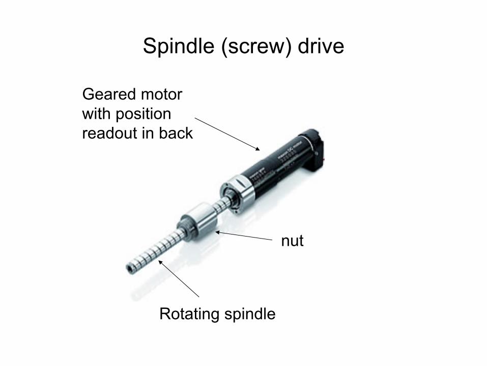
Spindle (screw) drive
Geared motor with position readout in back
Rotating spindle
nut
Limitations of analogue devices
•
Precision of potentiometer ~ 0.1% linearity– 0.4 mm for 40x40cm2
field
–
Sensitive to small changes in wire resistance–
Degraded accuracy by use and age (brush)
–
Sensitive to power supply voltage•
Reading accuracy ~ 0.2% –
Digital readout -
used even in early linacs
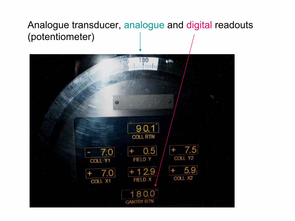
Analogue transducer, analogue
and digital
readouts(potentiometer)

Single-hand clock: purely analogue display Reading accuracy about 6 minutes ~ 1%
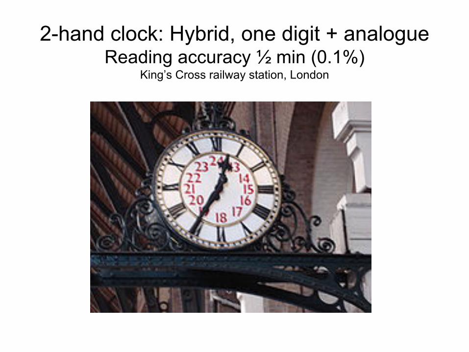
2-hand clock: Hybrid, one digit + analogue Reading accuracy ½
min (0.1%)
King’s Cross railway station, London

3-hand clock: Hybrid, two digits + analogue Reading accuracy ½
sec ~ 0.001%

“Analogue”
precision transducers
•
Geared potentiometers–
“Hour hand”
pot goes around once
–
“Minute hand”
pot goes around many times–
0.01% rotational precision readily obtained with 0.2% accuracy pots
•
Geared (dual) resolvers –
same principle
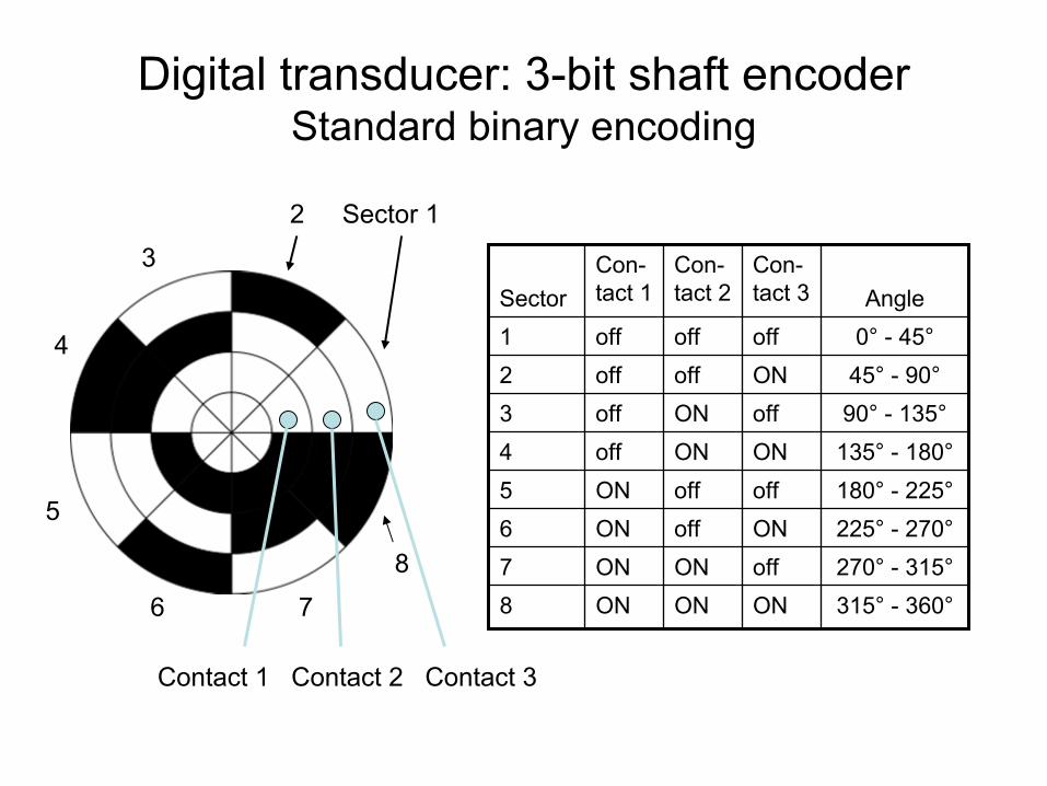
Digital transducer: 3-bit shaft encoder Standard binary encoding
SectorCon-
tact 1
Con-
tact 2
Con-
tact 3 Angle
1 off off off 0°
-
45°2 off off ON 45°
-
90°3 off ON off 90°
-
135°4 off ON ON 135°
-
180°5 ON off off 180°
-
225°6 ON off ON 225°
-
270°7 ON ON off 270°
-
315°8 ON ON ON 315°
-
360°
Contact 1 Contact 2 Contact 3
2 Sector 1
3
8
7
4
5
6
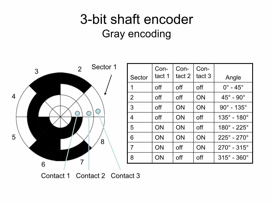
SectorCon-
tact 1
Con-
tact 2
Con-
tact 3 Angle
1 off off off 0°
-
45°2 off off ON 45°
-
90°3 off ON ON 90°
-
135°4 off ON off 135°
-
180°5 ON ON off 180°
-
225°6 ON ON ON 225°
-
270°7 ON off ON 270°
-
315°8 ON off off 315°
-
360°
3-bit shaft encoder Gray encoding
3 2 Sector 1
Contact 1 Contact 2 Contact 3
8
4
5
6 7
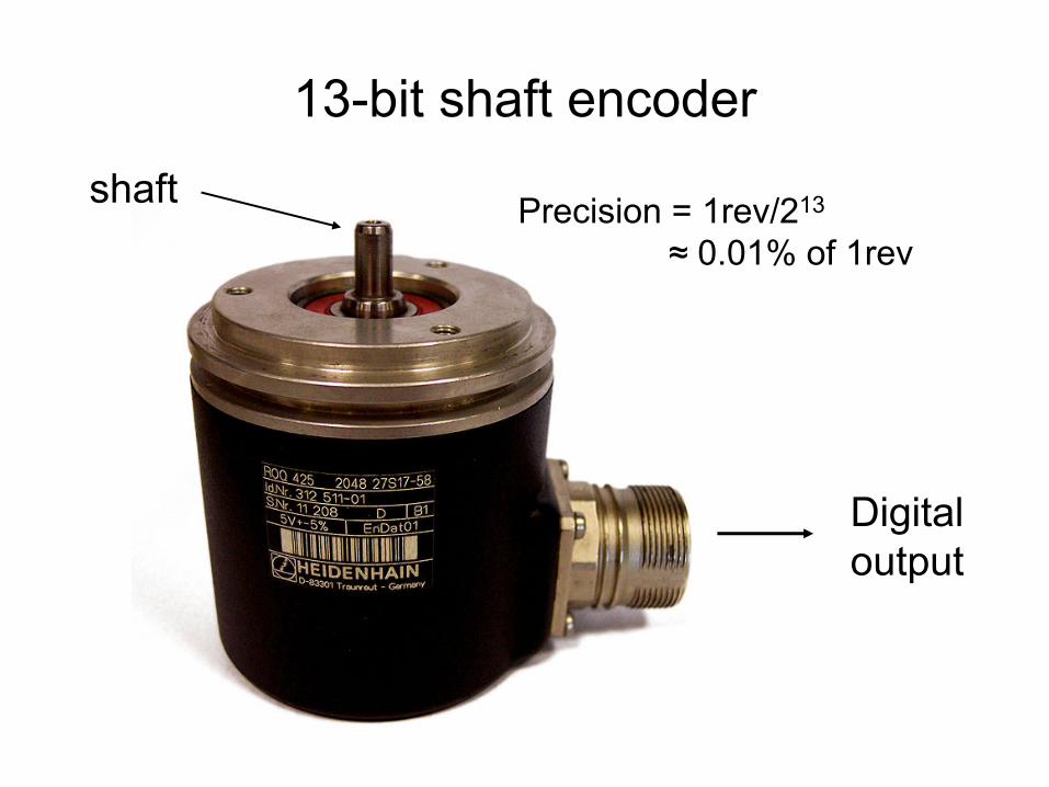
13-bit shaft encoder
Precision = 1rev/213
≈
0.01% of 1rev
shaft
Digital output
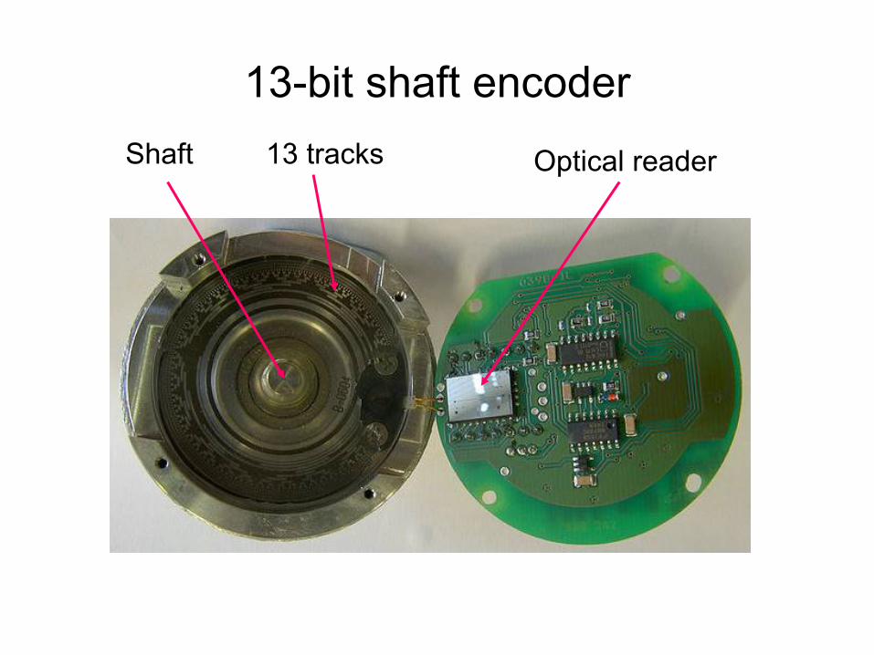
13-bit shaft encoder
Optical readerShaft 13 tracks
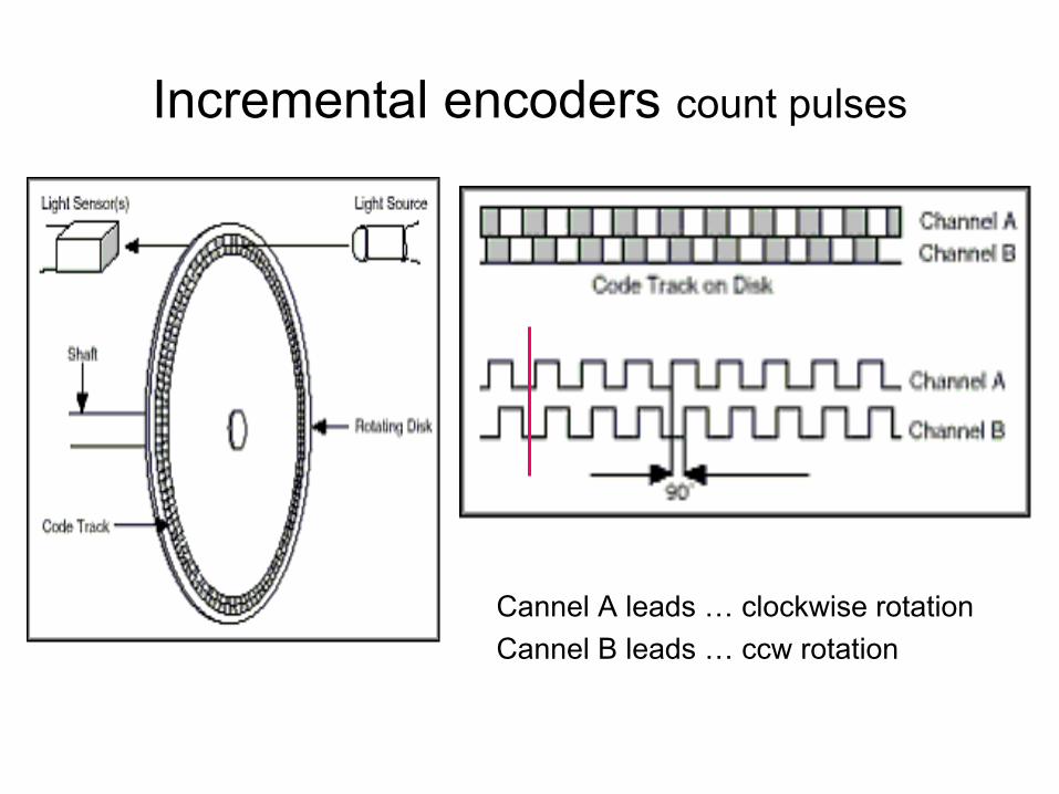
Incremental encoders count pulses
Cannel A leads …
clockwise rotationCannel B leads …
ccw rotation
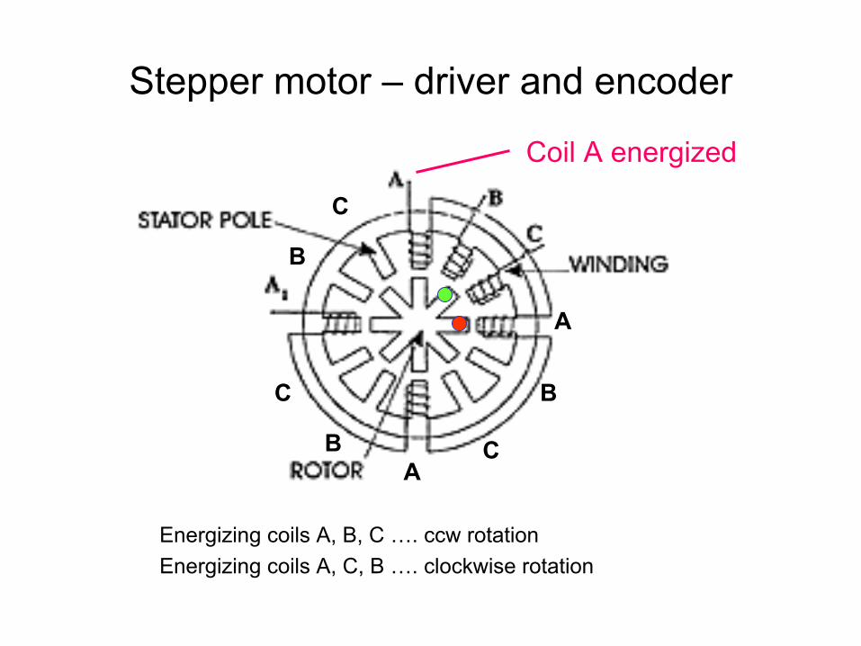
Stepper motor –
driver and encoder
Energizing coils A, B, C …. ccw rotationEnergizing coils A, C, B …. clockwise rotation
Coil A energized
A
A
B
B C
B
C
C
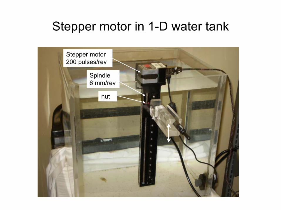
Stepper motor in 1-D water tank
Stepper motor200 pulses/rev
Spindle6 mm/rev
nut
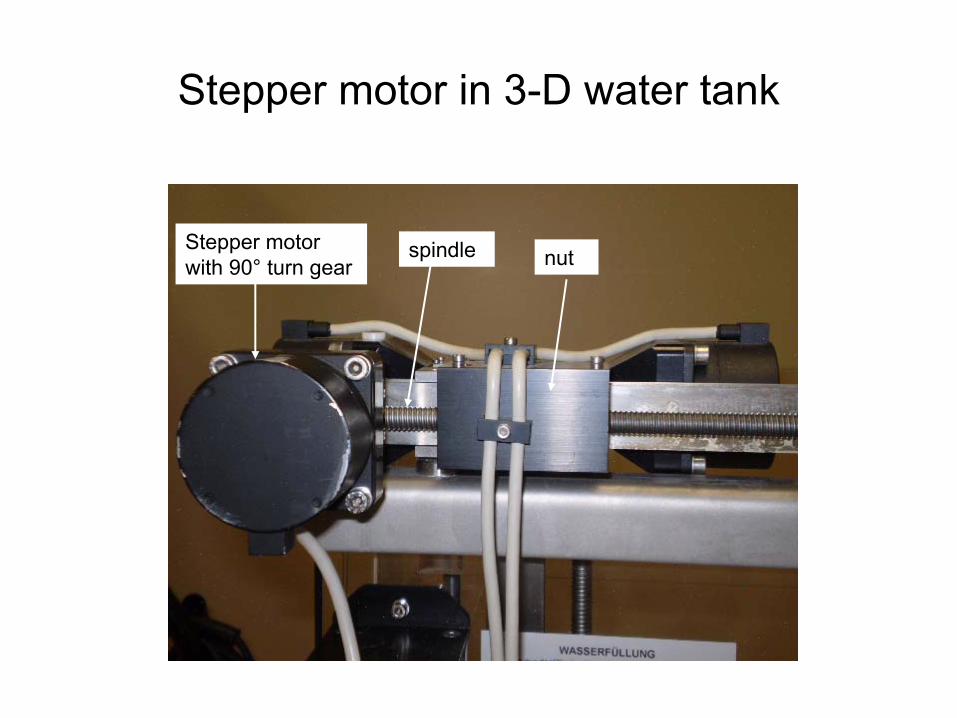
Stepper motor in 3-D water tank
Stepper motor with 90°
turn gearspindle nut
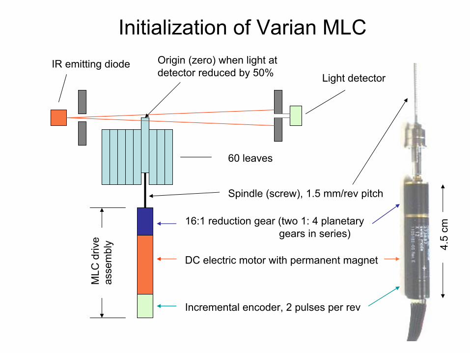
Initialization of Varian MLCIR emitting diode
16:1 reduction gear (two 1: 4 planetary gears in series)
DC electric motor with permanent magnet
Incremental encoder, 2 pulses per rev
Light detector
Spindle (screw), 1.5 mm/rev pitch
Origin (zero) when light at detector reduced by 50%
60 leaves
MLC
driv
e as
sem
bly 4.5
cm
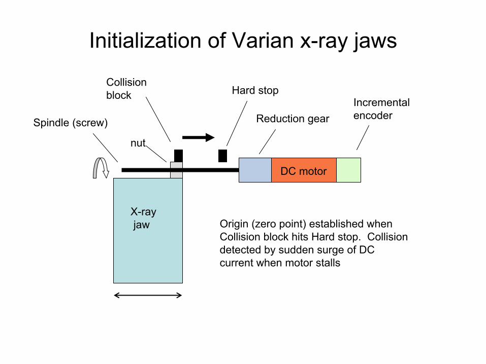
Initialization of Varian x-ray jaws
Hard stop Collision block
X-rayjaw Origin (zero point) established when
Collision block hits Hard stop. Collision detected by sudden surge of DC current when motor stalls
DC motor
Reduction gearIncremental encoder
Spindle (screw)
nut
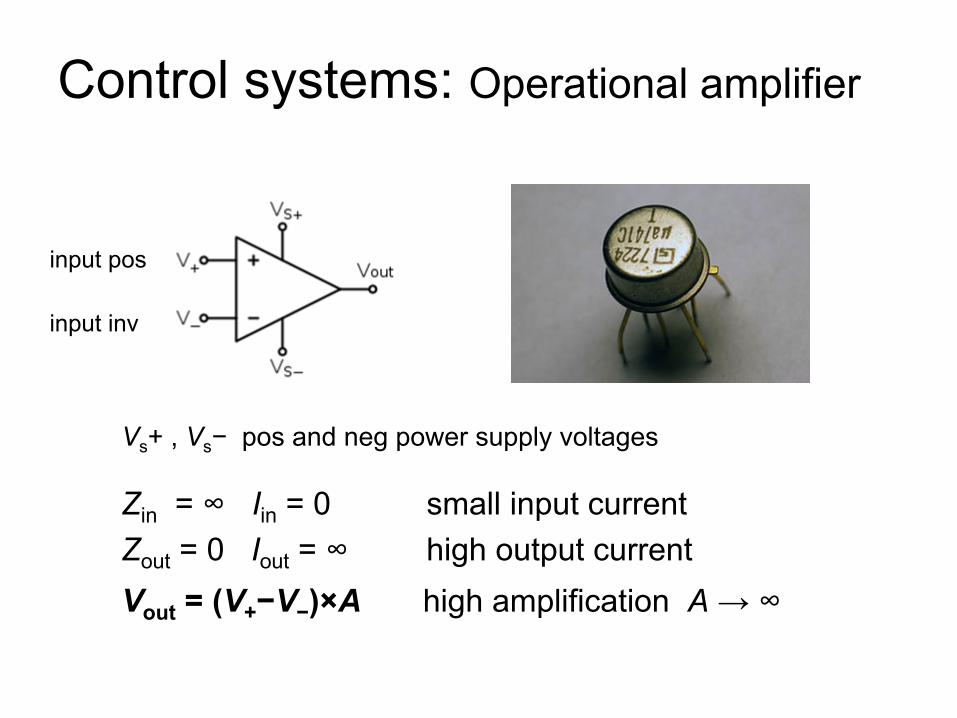
Control systems: Operational amplifier
Zin
= ∞ Iin
= 0 small input currentZout
= 0 Iout
= ∞
high output currentVout
= (V+
−V−
)×A high amplification A
→ ∞
Vs
+ , Vs
−
pos and neg
power supply voltages
input pos
input inv
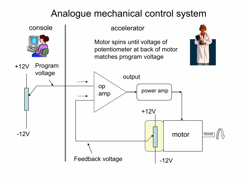
console
motor
+12V
-12V
-12V
+12V
Motor spins until voltage of potentiometer at back of motor matches program voltage
output
accelerator
op amp
Program voltage
Feedback voltage
power amp
Analogue mechanical control system
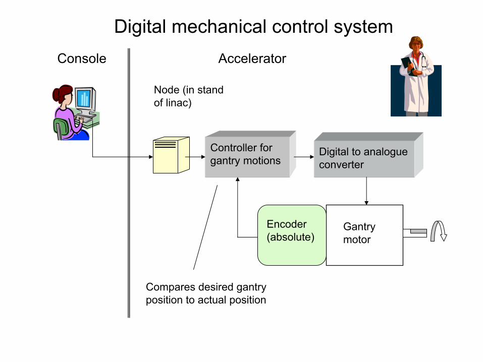
Console
Gantry motor
Accelerator
Digital mechanical control system
Node (in stand of linac)
Controller for gantry motions
Digital to analogue converter
Encoder (absolute)
Compares desired gantry position to actual position
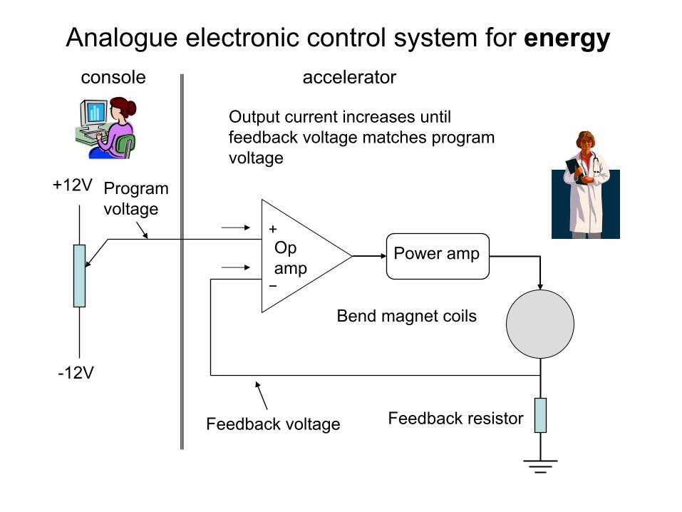
console
-12V
+12V
Output current increases until feedback voltage matches program voltage
accelerator
Op amp
Program voltage
Feedback voltage
Power amp
Feedback resistor
Bend magnet coils
Analogue electronic control system for energy
+
−
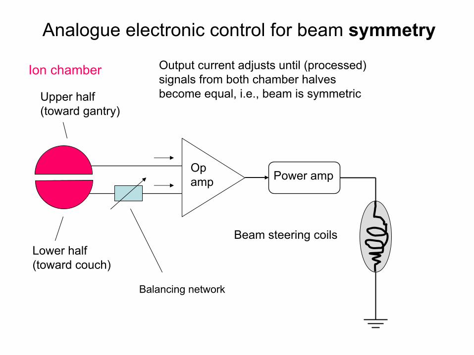
Output current adjusts until (processed) signals from both chamber halves become equal, i.e., beam is symmetric
Ion
chamber
Op amp Power amp
Beam steering coils
Analogue electronic control for beam symmetry
Lower half(toward couch)
Upper half(toward gantry)
Balancing network
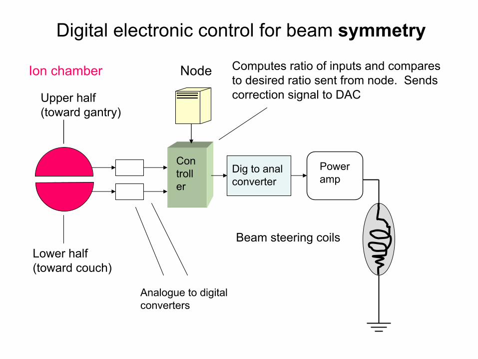
Computes ratio of inputs and compares to desired ratio sent from node. Sends correction signal to DAC
Ion
chamber
Power amp
Beam steering coils
Digital electronic control for beam symmetry
Lower half(toward couch)
Upper half(toward gantry)
Analogue to digital converters
Con
troll
er
Node
Dig to anal converter
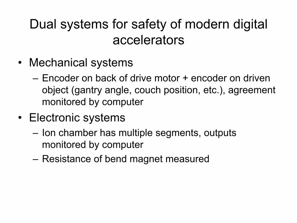
Dual systems for safety of modern digital accelerators
•
Mechanical systems–
Encoder on back of drive motor + encoder on driven object (gantry angle, couch position, etc.), agreement monitored by computer
•
Electronic systems–
Ion chamber has multiple segments, outputs monitored by computer
–
Resistance of bend magnet measured
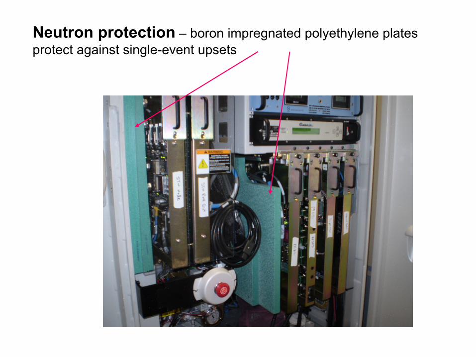
Neutron protection
–
boron impregnated polyethylene platesprotect against single-event upsets
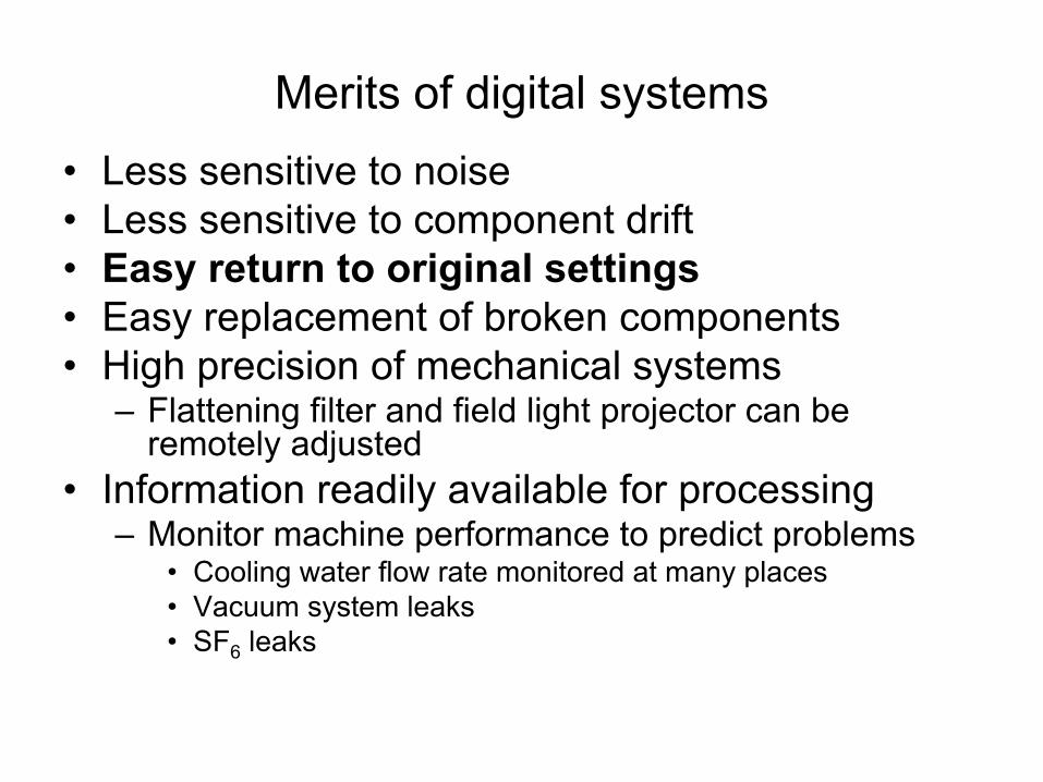
Merits of digital systems•
Less sensitive to noise
•
Less sensitive to component drift•
Easy return to original settings
•
Easy replacement of broken components•
High precision of mechanical systems–
Flattening filter and field light projector can be remotely adjusted
•
Information readily available for processing–
Monitor machine performance to predict problems
•
Cooling water flow rate monitored at many places•
Vacuum system leaks•
SF6
leaks
Merits of digital systems
•
Take into account “second order effects”–
Flexing of image receiver arm
•
Automatic tuning–
Slow changes of components
•
Thyratron
aging•
Waveguide resonant frequency