Embed Size (px)
Citation preview
1
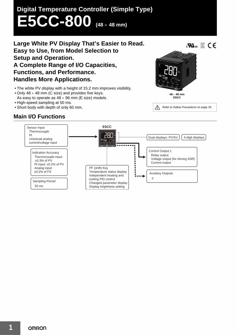
Digital Temperature Controller (Simple Type)
E5CC-800 (48 × 48 mm)
Large White PV Display That’s Easier to Read.Easy to Use, from Model Selection toSetup and Operation.A Complete Range of I/O Capacities, Functions, and Performance.Handles More Applications.• The white PV display with a height of 15.2 mm improves visibility.• Only 48 × 48 mm (C size) and provides five keys.
As easy to operate as 48 × 96 mm (E size) models.• High-speed sampling at 50 ms.• Short body with depth of only 60 mm.
Main I/O Functions
48 × 48 mmE5CC
Refer to Safety Precautions on page 29.
Sensor Input
Dual displays: PV/SV 4-digit displays
E5CC• Thermocouple• Pt• Universal analog
current/voltage input
Indication Accuracy• Thermocouple input:
±0.3% of PV• Pt input: ±0.2% of PV• Analog input:
±0.2% of FS
Sampling Period
• 50 ms
Control Output 1• Relay output• Voltage output (for driving SSR)• Current output
• PF (shift) Key• Temperature status display• Independent heating and
cooling PID control• Changed parameter display• Display brightness setting
Auxiliary Outputs
• 2
E5CC-800
2
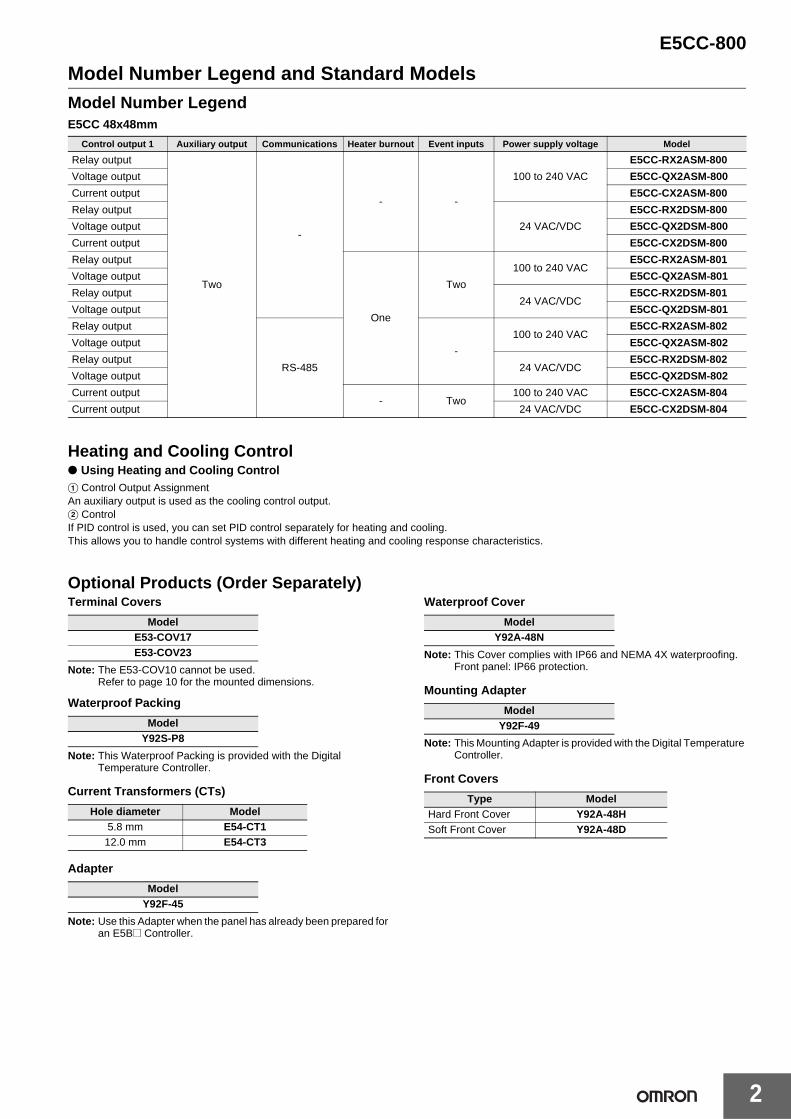
Model Number Legend and Standard ModelsModel Number LegendE5CC 48x48mm
Heating and Cooling Control● Using Heating and Cooling ControlA Control Output AssignmentAn auxiliary output is used as the cooling control output.B ControlIf PID control is used, you can set PID control separately for heating and cooling.This allows you to handle control systems with different heating and cooling response characteristics.
Optional Products (Order Separately)Terminal Covers
Note: The E53-COV10 cannot be used.Refer to page 10 for the mounted dimensions.
Waterproof Packing
Note: This Waterproof Packing is provided with the Digital Temperature Controller.
Current Transformers (CTs)
Adapter
Note: Use this Adapter when the panel has already been prepared for an E5B@ Controller.
Waterproof Cover
Note: This Cover complies with IP66 and NEMA 4X waterproofing.Front panel: IP66 protection.
Mounting Adapter
Note: This Mounting Adapter is provided with the Digital Temperature Controller.
Front Covers
Control output 1 Auxiliary output Communications Heater burnout Event inputs Power supply voltage Model
Relay output
Two
-
- -
100 to 240 VAC
E5CC-RX2ASM-800
Voltage output E5CC-QX2ASM-800
Current output E5CC-CX2ASM-800
Relay output
24 VAC/VDC
E5CC-RX2DSM-800
Voltage output E5CC-QX2DSM-800
Current output E5CC-CX2DSM-800
Relay output
One
Two
100 to 240 VACE5CC-RX2ASM-801
Voltage output E5CC-QX2ASM-801
Relay output24 VAC/VDC
E5CC-RX2DSM-801
Voltage output E5CC-QX2DSM-801
Relay output
RS-485
-
100 to 240 VACE5CC-RX2ASM-802
Voltage output E5CC-QX2ASM-802
Relay output24 VAC/VDC
E5CC-RX2DSM-802
Voltage output E5CC-QX2DSM-802
Current output- Two
100 to 240 VAC E5CC-CX2ASM-804
Current output 24 VAC/VDC E5CC-CX2DSM-804
ModelE53-COV17E53-COV23
ModelY92S-P8
Hole diameter Model5.8 mm E54-CT1
12.0 mm E54-CT3
ModelY92F-45
ModelY92A-48N
ModelY92F-49
Type ModelHard Front Cover Y92A-48HSoft Front Cover Y92A-48D
E5CC-800
3
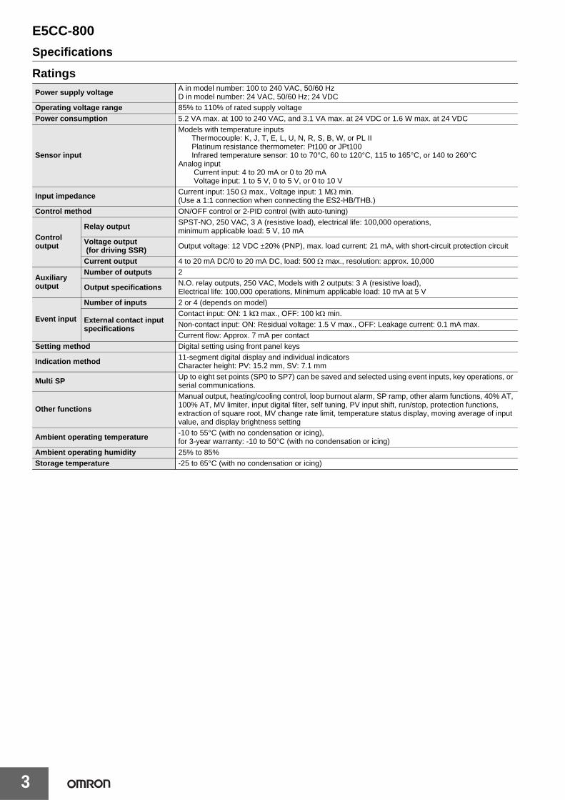
Specifications
RatingsPower supply voltage A in model number: 100 to 240 VAC, 50/60 Hz
D in model number: 24 VAC, 50/60 Hz; 24 VDCOperating voltage range 85% to 110% of rated supply voltagePower consumption 5.2 VA max. at 100 to 240 VAC, and 3.1 VA max. at 24 VDC or 1.6 W max. at 24 VDC
Sensor input
Models with temperature inputsThermocouple: K, J, T, E, L, U, N, R, S, B, W, or PL IIPlatinum resistance thermometer: Pt100 or JPt100Infrared temperature sensor: 10 to 70°C, 60 to 120°C, 115 to 165°C, or 140 to 260°C
Analog input Current input: 4 to 20 mA or 0 to 20 mA Voltage input: 1 to 5 V, 0 to 5 V, or 0 to 10 V
Input impedance Current input: 150 Ω max., Voltage input: 1 MΩ min. (Use a 1:1 connection when connecting the ES2-HB/THB.)
Control method ON/OFF control or 2-PID control (with auto-tuning)
Control output
Relay output SPST-NO, 250 VAC, 3 A (resistive load), electrical life: 100,000 operations, minimum applicable load: 5 V, 10 mA
Voltage output (for driving SSR) Output voltage: 12 VDC ±20% (PNP), max. load current: 21 mA, with short-circuit protection circuit
Current output 4 to 20 mA DC/0 to 20 mA DC, load: 500 Ω max., resolution: approx. 10,000
Auxiliary output
Number of outputs 2
Output specifications N.O. relay outputs, 250 VAC, Models with 2 outputs: 3 A (resistive load), Electrical life: 100,000 operations, Minimum applicable load: 10 mA at 5 V
Event input
Number of inputs 2 or 4 (depends on model)
External contact input specifications
Contact input: ON: 1 kΩ max., OFF: 100 kΩ min.Non-contact input: ON: Residual voltage: 1.5 V max., OFF: Leakage current: 0.1 mA max.Current flow: Approx. 7 mA per contact
Setting method Digital setting using front panel keys
Indication method 11-segment digital display and individual indicatorsCharacter height: PV: 15.2 mm, SV: 7.1 mm
Multi SP Up to eight set points (SP0 to SP7) can be saved and selected using event inputs, key operations, or serial communications.
Other functions
Manual output, heating/cooling control, loop burnout alarm, SP ramp, other alarm functions, 40% AT, 100% AT, MV limiter, input digital filter, self tuning, PV input shift, run/stop, protection functions, extraction of square root, MV change rate limit, temperature status display, moving average of input value, and display brightness setting
Ambient operating temperature -10 to 55°C (with no condensation or icing), for 3-year warranty: -10 to 50°C (with no condensation or icing)
Ambient operating humidity 25% to 85%Storage temperature -25 to 65°C (with no condensation or icing)
E5CC-800
4
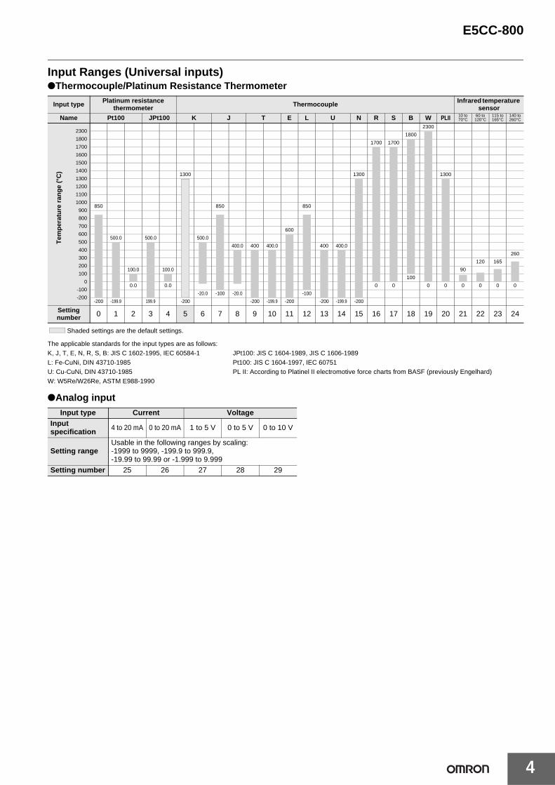
Input Ranges (Universal inputs)●Thermocouple/Platinum Resistance Thermometer
Shaded settings are the default settings.
The applicable standards for the input types are as follows:K, J, T, E, N, R, S, B: JIS C 1602-1995, IEC 60584-1 JPt100: JIS C 1604-1989, JIS C 1606-1989L: Fe-CuNi, DIN 43710-1985 Pt100: JIS C 1604-1997, IEC 60751U: Cu-CuNi, DIN 43710-1985 PL II: According to Platinel II electromotive force charts from BASF (previously Engelhard)W: W5Re/W26Re, ASTM E988-1990
●Analog input
Input type Platinum resistance thermometer Thermocouple Infrared temperature
sensor
Name Pt100 JPt100 K J T E L U N R S B W PLII 10 to 70°C
60 to 120°C
115 to 165°C
140 to 260°C
2300
1800
1700
1600
1500
1400
1300
1200
1100
1000
900
800
700
600
500
400
300
200
100
0
-100
-200
2300
1800
1700 1700
1300 1300 1300
850 850 850
600
500.0 500.0 500.0
400.0 400 400.0 400 400.0
260
120 165
100.0 100.0 90
100
0.0 0.0 0 0 0 0 0 0 0 0
-20.0 -100 -20.0 -100
-200 -199.9 199.9 -200 -200 -199.9 -200 -200 -199.9 -200
Setting number 0 1 2 3 4 5 6 7 8 9 10 11 12 13 14 15 16 17 18 19 20 21 22 23 24
Input type Current VoltageInput specification 4 to 20 mA 0 to 20 mA 1 to 5 V 0 to 5 V 0 to 10 V
Setting rangeUsable in the following ranges by scaling:-1999 to 9999, -199.9 to 999.9, -19.99 to 99.99 or -1.999 to 9.999
Setting number 25 26 27 28 29
T
emp
erat
ure
ran
ge
(°C
)
E5CC-800
5
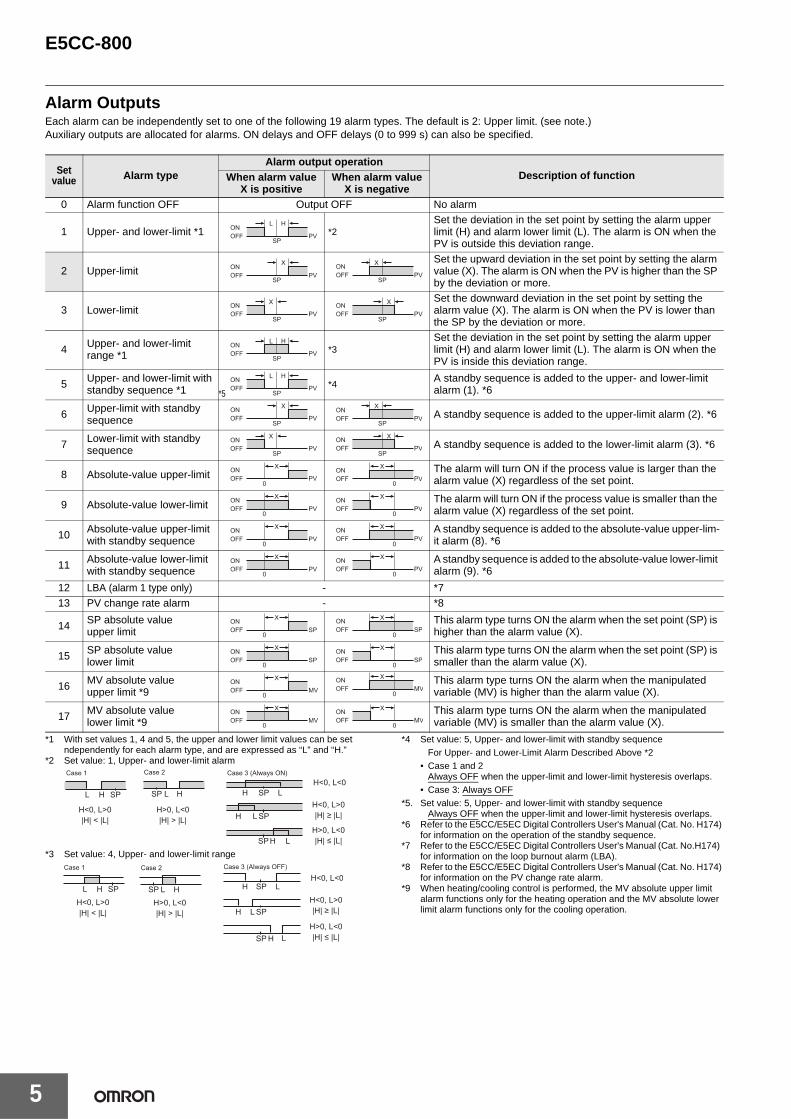
Alarm OutputsEach alarm can be independently set to one of the following 19 alarm types. The default is 2: Upper limit. (see note.)Auxiliary outputs are allocated for alarms. ON delays and OFF delays (0 to 999 s) can also be specified.
*1 With set values 1, 4 and 5, the upper and lower limit values can be set ndependently for each alarm type, and are expressed as “L” and “H.”
*2 Set value: 1, Upper- and lower-limit alarm
*3 Set value: 4, Upper- and lower-limit range
*4 Set value: 5, Upper- and lower-limit with standby sequenceFor Upper- and Lower-Limit Alarm Described Above *2
• Case 1 and 2Always OFF when the upper-limit and lower-limit hysteresis overlaps.
• Case 3: Always OFF*5. Set value: 5, Upper- and lower-limit with standby sequence
Always OFF when the upper-limit and lower-limit hysteresis overlaps.*6 Refer to the E5CC/E5EC Digital Controllers User's Manual (Cat. No. H174)
for information on the operation of the standby sequence.*7 Refer to the E5CC/E5EC Digital Controllers User's Manual (Cat. No.H174)
for information on the loop burnout alarm (LBA).*8 Refer to the E5CC/E5EC Digital Controllers User's Manual (Cat. No. H174)
for information on the PV change rate alarm.*9 When heating/cooling control is performed, the MV absolute upper limit
alarm functions only for the heating operation and the MV absolute lower limit alarm functions only for the cooling operation.
Set value Alarm type
Alarm output operationDescription of functionWhen alarm value
X is positiveWhen alarm value
X is negative0 Alarm function OFF Output OFF No alarm
1 Upper- and lower-limit *1 *2Set the deviation in the set point by setting the alarm upper limit (H) and alarm lower limit (L). The alarm is ON when the PV is outside this deviation range.
2 Upper-limitSet the upward deviation in the set point by setting the alarm value (X). The alarm is ON when the PV is higher than the SP by the deviation or more.
3 Lower-limitSet the downward deviation in the set point by setting the alarm value (X). The alarm is ON when the PV is lower than the SP by the deviation or more.
4 Upper- and lower-limit range *1
*3Set the deviation in the set point by setting the alarm upper limit (H) and alarm lower limit (L). The alarm is ON when the PV is inside this deviation range.
5 Upper- and lower-limit with standby sequence *1
*4A standby sequence is added to the upper- and lower-limit alarm (1). *6
6 Upper-limit with standby sequence A standby sequence is added to the upper-limit alarm (2). *6
7 Lower-limit with standby sequence A standby sequence is added to the lower-limit alarm (3). *6
8 Absolute-value upper-limit The alarm will turn ON if the process value is larger than the alarm value (X) regardless of the set point.
9 Absolute-value lower-limit The alarm will turn ON if the process value is smaller than the alarm value (X) regardless of the set point.
10 Absolute-value upper-limit with standby sequence
A standby sequence is added to the absolute-value upper-lim-it alarm (8). *6
11 Absolute-value lower-limit with standby sequence
A standby sequence is added to the absolute-value lower-limit alarm (9). *6
12 LBA (alarm 1 type only) - *713 PV change rate alarm - *8
14 SP absolute value upper limit
This alarm type turns ON the alarm when the set point (SP) is higher than the alarm value (X).
15 SP absolute value lower limit
This alarm type turns ON the alarm when the set point (SP) is smaller than the alarm value (X).
16 MV absolute value upper limit *9
This alarm type turns ON the alarm when the manipulated variable (MV) is higher than the alarm value (X).
17 MV absolute value lower limit *9
This alarm type turns ON the alarm when the manipulated variable (MV) is smaller than the alarm value (X).
ONOFF PV
SP
L H
SP
XONOFF PV
SP
XONOFF PV
SP
XONOFF PV
SP
XONOFF PV
SP
L HONOFF PV
SP
L HONOFF PV
*5
SP
XONOFF PV
SP
XONOFF PV
SP
XONOFF PV
SP
XONOFF PV
0
XONOFF PV
0
XONOFF PV
0
XONOFF PV
0
XONOFF PV
0
XONOFF PV
0
XONOFF PV
0
XONOFF PV
0
XONOFF PV
0
XONOFF SP
0
XONOFF SP
0
XONOFF SP
0
XONOFF SP
0
XONOFF MV 0
XONOFF MV
0
XONOFF MV
0
XONOFF MV
L H
H<0, L>0|H| < |L|
SP
Case 1
L H
H>0, L<0|H| > |L|
SP
Case 2
LHH<0, L<0
SP
LHH<0, L>0|H| ≥ |L|SP
LHH>0, L<0|H| ≤ |L|SP
Case 3 (Always ON)
L HH<0, L>0|H| < |L|
SP
Case 1
L HH>0, L<0|H| > |L|
SP
Case 2
LHH<0, L<0
SP
L
L
HH<0, L>0|H| ≥ |L|SP
HH>0, L<0|H| ≤ |L|SP
Case 3 (Always OFF)
E5CC-800
6
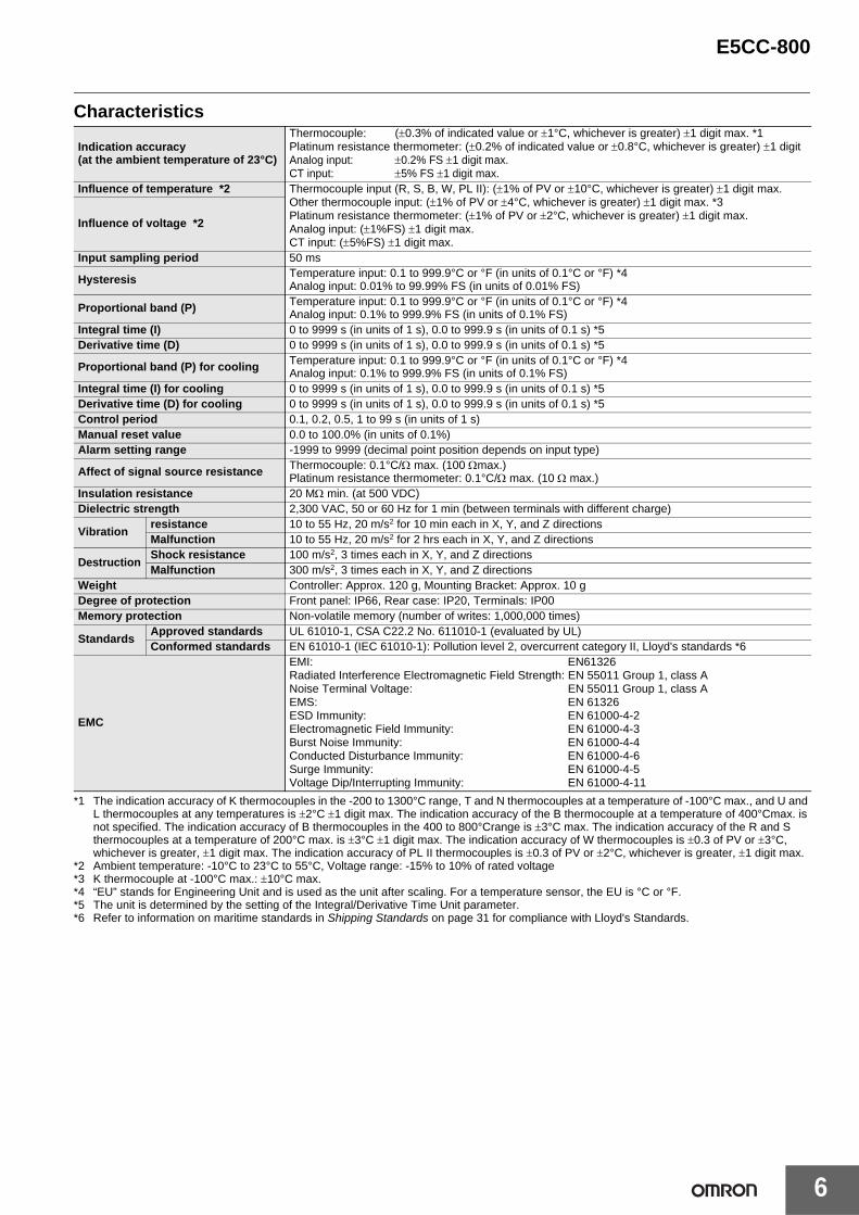
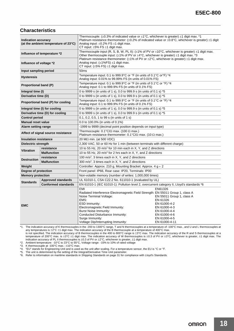
Characteristics
*1 The indication accuracy of K thermocouples in the -200 to 1300°C range, T and N thermocouples at a temperature of -100°C max., and U and L thermocouples at any temperatures is ±2°C ±1 digit max. The indication accuracy of the B thermocouple at a temperature of 400°Cmax. is not specified. The indication accuracy of B thermocouples in the 400 to 800°Crange is ±3°C max. The indication accuracy of the R and S thermocouples at a temperature of 200°C max. is ±3°C ±1 digit max. The indication accuracy of W thermocouples is ±0.3 of PV or ±3°C, whichever is greater, ±1 digit max. The indication accuracy of PL II thermocouples is ±0.3 of PV or ±2°C, whichever is greater, ±1 digit max.
*2 Ambient temperature: -10°C to 23°C to 55°C, Voltage range: -15% to 10% of rated voltage*3 K thermocouple at -100°C max.: ±10°C max.*4 “EU” stands for Engineering Unit and is used as the unit after scaling. For a temperature sensor, the EU is °C or °F.*5 The unit is determined by the setting of the Integral/Derivative Time Unit parameter.*6 Refer to information on maritime standards in Shipping Standards on page 31 for compliance with Lloyd's Standards.
Indication accuracy(at the ambient temperature of 23°C)
Thermocouple: (±0.3% of indicated value or ±1°C, whichever is greater) ±1 digit max. *1Platinum resistance thermometer: (±0.2% of indicated value or ±0.8°C, whichever is greater) ±1 digitAnalog input: ±0.2% FS ±1 digit max.CT input: ±5% FS ±1 digit max.
Influence of temperature *2 Thermocouple input (R, S, B, W, PL II): (±1% of PV or ±10°C, whichever is greater) ±1 digit max.Other thermocouple input: (±1% of PV or ±4°C, whichever is greater) ±1 digit max. *3Platinum resistance thermometer: (±1% of PV or ±2°C, whichever is greater) ±1 digit max.Analog input: (±1%FS) ±1 digit max.CT input: (±5%FS) ±1 digit max.
Influence of voltage *2
Input sampling period 50 ms
Hysteresis Temperature input: 0.1 to 999.9°C or °F (in units of 0.1°C or °F) *4Analog input: 0.01% to 99.99% FS (in units of 0.01% FS)
Proportional band (P) Temperature input: 0.1 to 999.9°C or °F (in units of 0.1°C or °F) *4Analog input: 0.1% to 999.9% FS (in units of 0.1% FS)
Integral time (I) 0 to 9999 s (in units of 1 s), 0.0 to 999.9 s (in units of 0.1 s) *5Derivative time (D) 0 to 9999 s (in units of 1 s), 0.0 to 999.9 s (in units of 0.1 s) *5
Proportional band (P) for cooling Temperature input: 0.1 to 999.9°C or °F (in units of 0.1°C or °F) *4Analog input: 0.1% to 999.9% FS (in units of 0.1% FS)
Integral time (I) for cooling 0 to 9999 s (in units of 1 s), 0.0 to 999.9 s (in units of 0.1 s) *5Derivative time (D) for cooling 0 to 9999 s (in units of 1 s), 0.0 to 999.9 s (in units of 0.1 s) *5Control period 0.1, 0.2, 0.5, 1 to 99 s (in units of 1 s)Manual reset value 0.0 to 100.0% (in units of 0.1%)Alarm setting range -1999 to 9999 (decimal point position depends on input type)
Affect of signal source resistance Thermocouple: 0.1°C/Ω max. (100 Ωmax.)Platinum resistance thermometer: 0.1°C/Ω max. (10 Ω max.)
Insulation resistance 20 MΩ min. (at 500 VDC)Dielectric strength 2,300 VAC, 50 or 60 Hz for 1 min (between terminals with different charge)
Vibrationresistance 10 to 55 Hz, 20 m/s2 for 10 min each in X, Y, and Z directionsMalfunction 10 to 55 Hz, 20 m/s2 for 2 hrs each in X, Y, and Z directions
DestructionShock resistance 100 m/s2, 3 times each in X, Y, and Z directionsMalfunction 300 m/s2, 3 times each in X, Y, and Z directions
Weight Controller: Approx. 120 g, Mounting Bracket: Approx. 10 gDegree of protection Front panel: IP66, Rear case: IP20, Terminals: IP00Memory protection Non-volatile memory (number of writes: 1,000,000 times)
StandardsApproved standards UL 61010-1, CSA C22.2 No. 611010-1 (evaluated by UL)Conformed standards EN 61010-1 (IEC 61010-1): Pollution level 2, overcurrent category II, Lloyd's standards *6
EMC
EMI: EN61326Radiated Interference Electromagnetic Field Strength: EN 55011 Group 1, class ANoise Terminal Voltage: EN 55011 Group 1, class AEMS: EN 61326ESD Immunity: EN 61000-4-2Electromagnetic Field Immunity: EN 61000-4-3Burst Noise Immunity: EN 61000-4-4Conducted Disturbance Immunity: EN 61000-4-6Surge Immunity: EN 61000-4-5Voltage Dip/Interrupting Immunity: EN 61000-4-11
E5CC-800
7
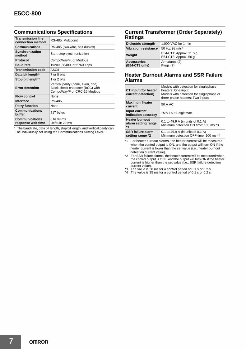
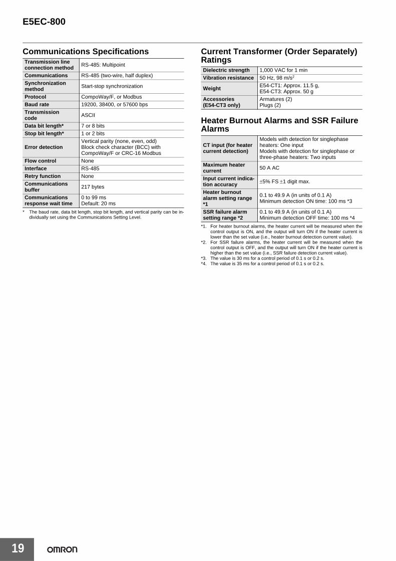
Communications Specifications
* The baud rate, data bit length, stop bit length, and vertical parity can be individually set using the Communications Setting Level.
Current Transformer (Order Separately) Ratings
Heater Burnout Alarms and SSR Failure Alarms
*1 For heater burnout alarms, the heater current will be measured when the control output is ON, and the output will turn ON if the heater current is lower than the set value (i.e., heater burnout detection current value).
*2 For SSR failure alarms, the heater current will be measured when the control output is OFF, and the output will turn ON if the heater current is higher than the set value (i.e., SSR failure detection current value).
*3 The value is 30 ms for a control period of 0.1 s or 0.2 s.*4 The value is 35 ms for a control period of 0.1 s or 0.2 s.
Transmission line connection method RS-485: Multipoint
Communications RS-485 (two-wire, half duplex)Synchronization method Start-stop synchronization
Protocol CompoWay/F, or ModbusBaud rate 19200, 38400, or 57600 bpsTransmission code ASCIIData bit length* 7 or 8 bitsStop bit length* 1 or 2 bits
Error detectionVertical parity (none, even, odd)Block check character (BCC) withCompoWay/F or CRC-16 Modbus
Flow control NoneInterface RS-485Retry function NoneCommunications buffer 217 bytes
Communications response wait time
0 to 99 msDefault: 20 ms
Dielectric strength 1,000 VAC for 1 minVibration resistance 50 Hz, 98 m/s2
Weight E54-CT1: Approx. 11.5 g, E54-CT3: Approx. 50 g
Accessories(E54-CT3 only)
Armatures (2)Plugs (2)
CT input (for heater current detection)
Models with detection for singlephase heaters: One inputModels with detection for singlephase or three-phase heaters: Two inputs
Maximum heater current 50 A AC
Input current indication accuracy ±5% FS ±1 digit max.
Heater burnout alarm setting range *1
0.1 to 49.9 A (in units of 0.1 A)Minimum detection ON time: 100 ms *3
SSR failure alarm setting range *2
0.1 to 49.9 A (in units of 0.1 A)Minimum detection OFF time: 100 ms *4
E5CC-800
8
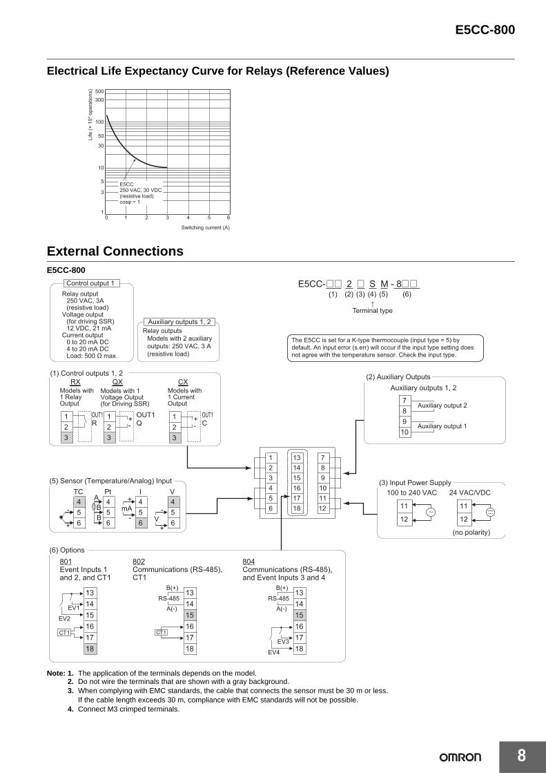
Electrical Life Expectancy Curve for Relays (Reference Values)
External ConnectionsE5CC-800
Note: 1. The application of the terminals depends on the model.2. Do not wire the terminals that are shown with a gray background.3. When complying with EMC standards, the cable that connects the sensor must be 30 m or less.
If the cable length exceeds 30 m, compliance with EMC standards will not be possible.4. Connect M3 crimped terminals.
500300
100
50
30
10
5
3
10 1 2 3 4 5 6
Switching current (A)
E5CC250 VAC, 30 VDC(resistive load)cosφ = 1
Life
(× 1
04 ope
ratio
ns)
The E5CC is set for a K-type thermocouple (input type = 5) by default. An input error (s.err) will occur if the input type setting does not agree with the temperature sensor. Check the input type.
Control output 1Relay output
250 VAC, 3A(resistive load)
Voltage output(for driving SSR)12 VDC, 21 mA
Current output0 to 20 mA DC4 to 20 mA DCLoad: 500 Ω max.
Relay outputsModels with 2 auxiliary outputs: 250 VAC, 3 A (resistive load)
1718 12
1516
12
1314
3
114
6
789
105
6
456
56
PtABB
+
-mA-
+
54
V
- 5V 6
+
4TC
4I
(no polarity)
11
12
11
12
100 to 240 VAC 24 VAC/VDC
Auxiliary outputs 1, 2
78910
Auxiliary output 2
Auxiliary output 1
161718
131415
13141516
131415161718
804Communications (RS-485), and Event Inputs 3 and 4
801Event Inputs 1 and 2, and CT1
1718
802Communications (RS-485), CT1
EV1
EV2
EV3
EV4
CT1
B(+)
A(-)RS-485
B(+)
A(-)RS-485
CT1
(2) Auxiliary Outputs
(3) Input Power Supply(5) Sensor (Temperature/Analog) Input
(6) Options
+-
3
123
12 -
Models with 1 Current Output
Models with 1 Relay Output
3
(1) Control outputs 1, 2
OUT1C
OUT1Q
OUT1R
12
Models with 1 Voltage Output (for Driving SSR)
+
RX QX CX
Auxiliary outputs 1, 2
E5CC-@@ 2 @ S M - 8@@ (1) (2) (3) (4) (5) (6)
↑Terminal type
E5CC-800
9
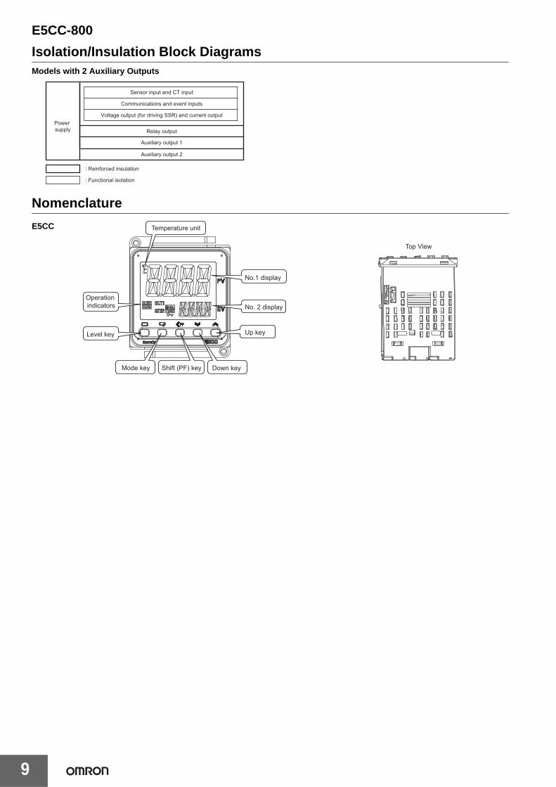
Isolation/Insulation Block DiagramsModels with 2 Auxiliary Outputs
Nomenclature
Communications and event inputs
Sensor input and CT input
Voltage output (for driving SSR) and current output
Relay output
Auxiliary output 1
Power supply
Auxiliary output 2
: Reinforced insulation
: Functional isolation
E5CC
Top View
Level key
Temperature unit
No.1 display
No. 2 display
Up key
Mode key Shift (PF) key Down key
Operation indicators
E5CC-800
10
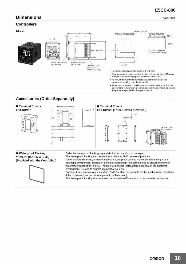
Dimensions (Unit: mm)
Controllers
Accessories (Order Separately)
45+0.6 0
45+0.6
0
45+0.6
0
60 min.
(48 × number of units - 2.5)+1.0 0
Group mounting does not allow waterproofing.
Panel CutoutMounted Separately Group Mounted
48 × 48
4
1
73.1
60
Mounting Adapter(Accessory) Terminal Cover
(E53-COV17)(Sold separately)
5848.8
Waterproof Packing (Accessory)
44.8 × 44.8
E5CC
• Recommended panel thickness is 1 to 5 mm.• Group mounting is not possible in the vertical direction. (Maintain
the specified mounting space between Controllers.)• To mount the Controller so that it is waterproof, insert the
waterproof packing onto the Controller.• When two or more Controllers are mounted, make sure that the
surrounding temperature does not exceed the allowable operating temperature specified in the specifications.
48
48.8
22
9.1
10
44.8
2 3.8
Terminal Cover (E53-COV23)
● Terminal CoversE53-COV17
● Terminal CoversE53-COV23 (Three Covers provided.)
● Waterproof PackingY92S-P8 (for DIN 48 × 48)(Provided with the Controller.)
Order the Waterproof Packing separately if it becomes lost or damaged.The Waterproof Packing can be used to achieve an IP66 degree of protection.(Deterioration, shrinking, or hardening of the waterproof packing may occur depending on the operating environment. Therefore, periodic replacement is recommended to ensure the level of waterproofing specified in IP66. The time for periodic replacement depends on the operating environment. Be sure to confirm this point at your site.Consider three years a rough standard. OMRON shall not be liable for the level of water resistance if the customer does not perform periodic replacement.)The Waterproof Packing does not need to be attached if a waterproof structure is not required.
E5CC-800
11
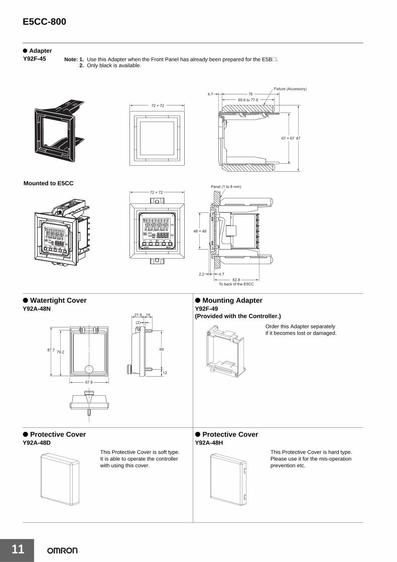
● Adapter
● Watertight CoverY92A-48N
● Mounting AdapterY92F-49(Provided with the Controller.)
● Protective CoverY92A-48D
● Protective CoverY92A-48H
Fixture (Accessory)
69.6 to 77.6
8767 × 67
72 × 72
764.7
72 × 72
48 × 48
Panel (1 to 8 mm)
62.8To back of the E5CC
2.2 4.7
Y92F-45
Mounted to E5CC
Note: 1. Use this Adapter when the Front Panel has already been prepared for the [email protected]. Only black is available.
67.6
69
12
21.9 14
(2)
79.287.7
Order this Adapter separately if it becomes lost or damaged.
This Protective Cover is soft type. It is able to operate the controller with using this cover.
This Protective Cover is hard type.Please use it for the mis-operation prevention etc.
E5CC-800
12
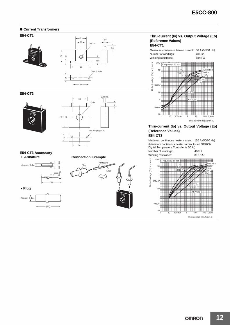
● Current Transformers
E54-CT3 Accessory• Armature
30
21
155.8 dia.
25 3
40
10.5
2.8
7.5
10
Two, 3.5 dia.
40 × 40
30
12 dia.9
2.36 dia.
15
30
Two, M3 (depth: 4)
Approx. 3 dia.
18
(22)
Approx. 6 dia.
PlugArmature
Lead
E54-CT1
E54-CT3
Connection Example
• Plug
Thru-current (Io) vs. Output Voltage (Eo)(Reference Values)E54-CT1Maximum continuous heater current: 50 A (50/60 Hz)Number of windings: 400±2Winding resistance: 18±2 Ω
Thru-current (Io) A (r.m.s.)
1 10 100mA 1 10 100 1,000A
100V Frequency: 50 Hz
Distortion factor 10%
3%1%
100Ω
RL=10Ω
∞10
1
100mV
10
1
100μV
10
1kΩ
Out
put v
olta
ge (E
o) V
(r.m
.s.)
Thru-current (Io) vs. Output Voltage (Eo)(Reference Values)E54-CT3Maximum continuous heater current: 120 A (50/60 Hz)(Maximum continuous heater current for an OMRON Digital Temperature Controller is 50 A.)Number of windings: 400±2Winding resistance: 8±0.8 Ω
Thru-current (Io) A (r.m.s.)
1 10 100mA 1 10 100 1,000A
100V Frequency: 50 HzDistortion factor 10%
3%1%
1kΩ
100Ω50Ω
RL=10Ω
500Ω
∞10
1
100mV
10
1
100μV
10
Out
put v
olta
ge (E
o) V
(r.m
.s.)
13
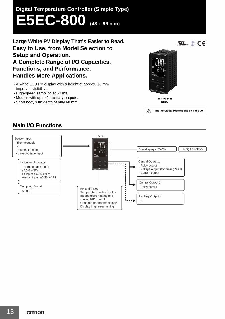
Digital Temperature Controller (Simple Type)
E5EC-800 (48 × 96 mm)
Large White PV Display That’s Easier to Read.Easy to Use, from Model Selection to Setup and Operation.A Complete Range of I/O Capacities, Functions, and Performance.Handles More Applications.• A white LCD PV display with a height of approx. 18 mm
improves visibility.• High-speed sampling at 50 ms.• Models with up to 2 auxiliary outputs.• Short body with depth of only 60 mm.
Main I/O Functions
48 × 96 mmE5EC
Refer to Safety Precautions on page 29.
E5EC
4-digit displays
Sensor Input • Thermocouple• Pt• Universal analog
current/voltage input
Indication Accuracy
• Thermocouple input: ±0.3% of PV
• Pt input: ±0.2% of PV• Analog input: ±0.2% of FS
Sampling Period
• 50 ms
Control Output 1• Relay output• Voltage output (for driving SSR)• Current output
Control Output 2
• Relay output
Auxiliary Outputs
• 2
• PF (shift) Key• Temperature status display• Independent heating and
cooling PID control• Changed parameter display• Display brightness setting
Dual displays: PV/SV
E5EC-800
14
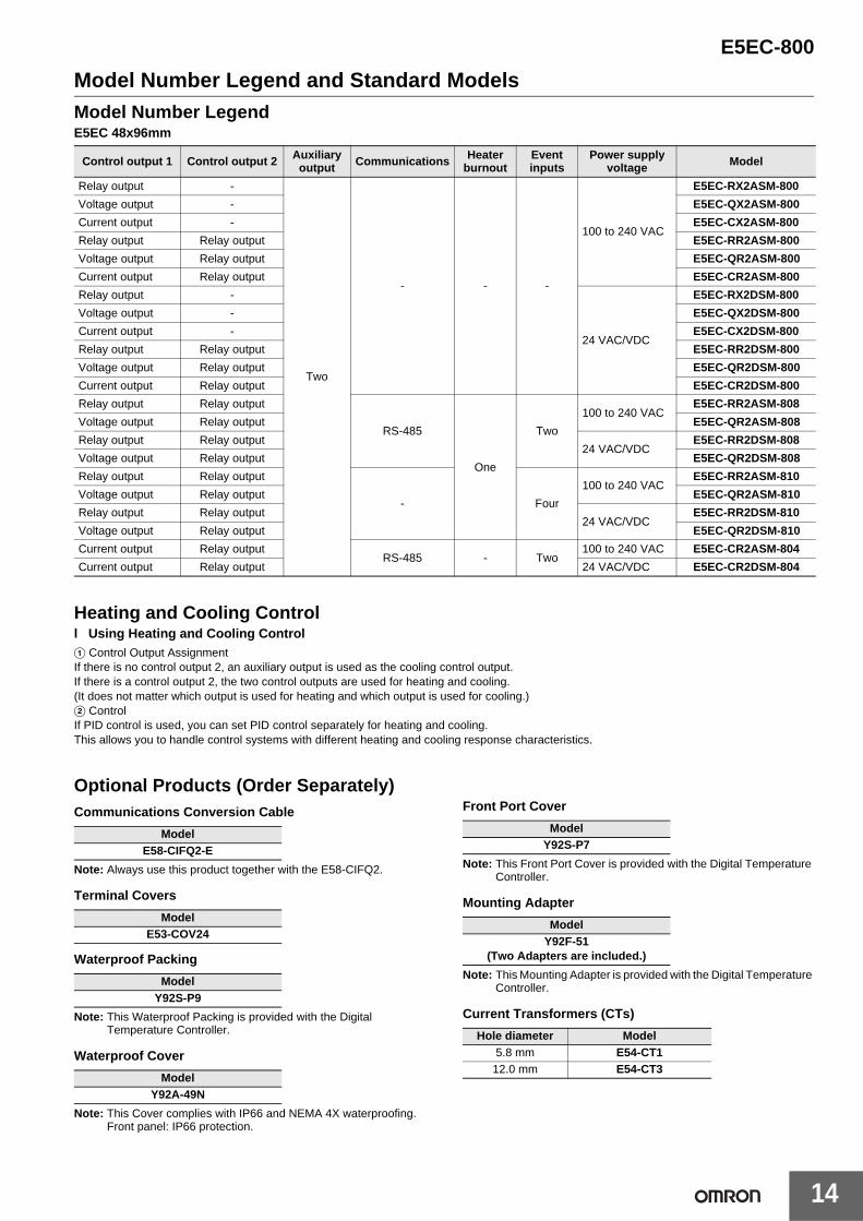
Model Number Legend and Standard ModelsModel Number LegendE5EC 48x96mm
Heating and Cooling Controll Using Heating and Cooling ControlA Control Output AssignmentIf there is no control output 2, an auxiliary output is used as the cooling control output.If there is a control output 2, the two control outputs are used for heating and cooling.(It does not matter which output is used for heating and which output is used for cooling.)B ControlIf PID control is used, you can set PID control separately for heating and cooling.This allows you to handle control systems with different heating and cooling response characteristics.
Optional Products (Order Separately)Communications Conversion Cable
Note: Always use this product together with the E58-CIFQ2.
Terminal Covers
Waterproof Packing
Note: This Waterproof Packing is provided with the Digital Temperature Controller.
Waterproof Cover
Note: This Cover complies with IP66 and NEMA 4X waterproofing.Front panel: IP66 protection.
Front Port Cover
Note: This Front Port Cover is provided with the Digital Temperature Controller.
Mounting Adapter
Note: This Mounting Adapter is provided with the Digital Temperature Controller.
Current Transformers (CTs)
Control output 1 Control output 2 Auxiliary output Communications Heater
burnoutEvent inputs
Power supply voltage Model
Relay output -
Two
- - -
100 to 240 VAC
E5EC-RX2ASM-800
Voltage output - E5EC-QX2ASM-800
Current output - E5EC-CX2ASM-800
Relay output Relay output E5EC-RR2ASM-800
Voltage output Relay output E5EC-QR2ASM-800
Current output Relay output E5EC-CR2ASM-800
Relay output -
24 VAC/VDC
E5EC-RX2DSM-800
Voltage output - E5EC-QX2DSM-800
Current output - E5EC-CX2DSM-800
Relay output Relay output E5EC-RR2DSM-800
Voltage output Relay output E5EC-QR2DSM-800
Current output Relay output E5EC-CR2DSM-800
Relay output Relay output
RS-485
One
Two
100 to 240 VACE5EC-RR2ASM-808
Voltage output Relay output E5EC-QR2ASM-808
Relay output Relay output24 VAC/VDC
E5EC-RR2DSM-808
Voltage output Relay output E5EC-QR2DSM-808
Relay output Relay output
- Four
100 to 240 VACE5EC-RR2ASM-810
Voltage output Relay output E5EC-QR2ASM-810
Relay output Relay output24 VAC/VDC
E5EC-RR2DSM-810
Voltage output Relay output E5EC-QR2DSM-810
Current output Relay outputRS-485 - Two
100 to 240 VAC E5EC-CR2ASM-804
Current output Relay output 24 VAC/VDC E5EC-CR2DSM-804
ModelE58-CIFQ2-E
ModelE53-COV24
ModelY92S-P9
ModelY92A-49N
ModelY92S-P7
ModelY92F-51
(Two Adapters are included.)
Hole diameter Model5.8 mm E54-CT1
12.0 mm E54-CT3
E5EC-800
15
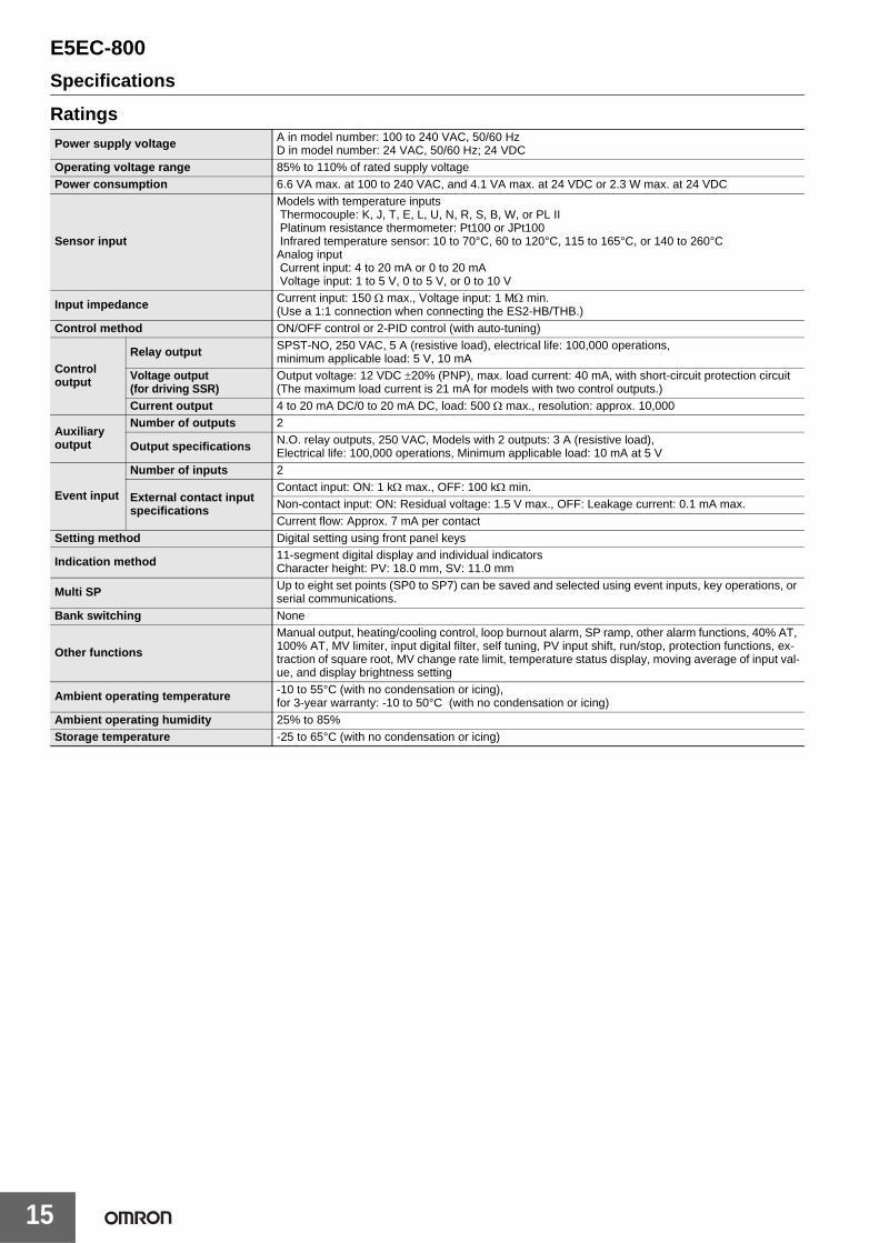
Specifications
RatingsPower supply voltage A in model number: 100 to 240 VAC, 50/60 Hz
D in model number: 24 VAC, 50/60 Hz; 24 VDCOperating voltage range 85% to 110% of rated supply voltagePower consumption 6.6 VA max. at 100 to 240 VAC, and 4.1 VA max. at 24 VDC or 2.3 W max. at 24 VDC
Sensor input
Models with temperature inputs Thermocouple: K, J, T, E, L, U, N, R, S, B, W, or PL II Platinum resistance thermometer: Pt100 or JPt100 Infrared temperature sensor: 10 to 70°C, 60 to 120°C, 115 to 165°C, or 140 to 260°CAnalog input Current input: 4 to 20 mA or 0 to 20 mA Voltage input: 1 to 5 V, 0 to 5 V, or 0 to 10 V
Input impedance Current input: 150 Ω max., Voltage input: 1 MΩ min. (Use a 1:1 connection when connecting the ES2-HB/THB.)
Control method ON/OFF control or 2-PID control (with auto-tuning)
Control output
Relay output SPST-NO, 250 VAC, 5 A (resistive load), electrical life: 100,000 operations, minimum applicable load: 5 V, 10 mA
Voltage output (for driving SSR)
Output voltage: 12 VDC ±20% (PNP), max. load current: 40 mA, with short-circuit protection circuit (The maximum load current is 21 mA for models with two control outputs.)
Current output 4 to 20 mA DC/0 to 20 mA DC, load: 500 Ω max., resolution: approx. 10,000
Auxiliary output
Number of outputs 2
Output specifications N.O. relay outputs, 250 VAC, Models with 2 outputs: 3 A (resistive load), Electrical life: 100,000 operations, Minimum applicable load: 10 mA at 5 V
Event input
Number of inputs 2
External contact input specifications
Contact input: ON: 1 kΩ max., OFF: 100 kΩ min.Non-contact input: ON: Residual voltage: 1.5 V max., OFF: Leakage current: 0.1 mA max.Current flow: Approx. 7 mA per contact
Setting method Digital setting using front panel keys
Indication method 11-segment digital display and individual indicatorsCharacter height: PV: 18.0 mm, SV: 11.0 mm
Multi SP Up to eight set points (SP0 to SP7) can be saved and selected using event inputs, key operations, or serial communications.
Bank switching None
Other functions
Manual output, heating/cooling control, loop burnout alarm, SP ramp, other alarm functions, 40% AT, 100% AT, MV limiter, input digital filter, self tuning, PV input shift, run/stop, protection functions, ex-traction of square root, MV change rate limit, temperature status display, moving average of input val-ue, and display brightness setting
Ambient operating temperature -10 to 55°C (with no condensation or icing), for 3-year warranty: -10 to 50°C (with no condensation or icing)
Ambient operating humidity 25% to 85%Storage temperature -25 to 65°C (with no condensation or icing)
E5EC-800
16
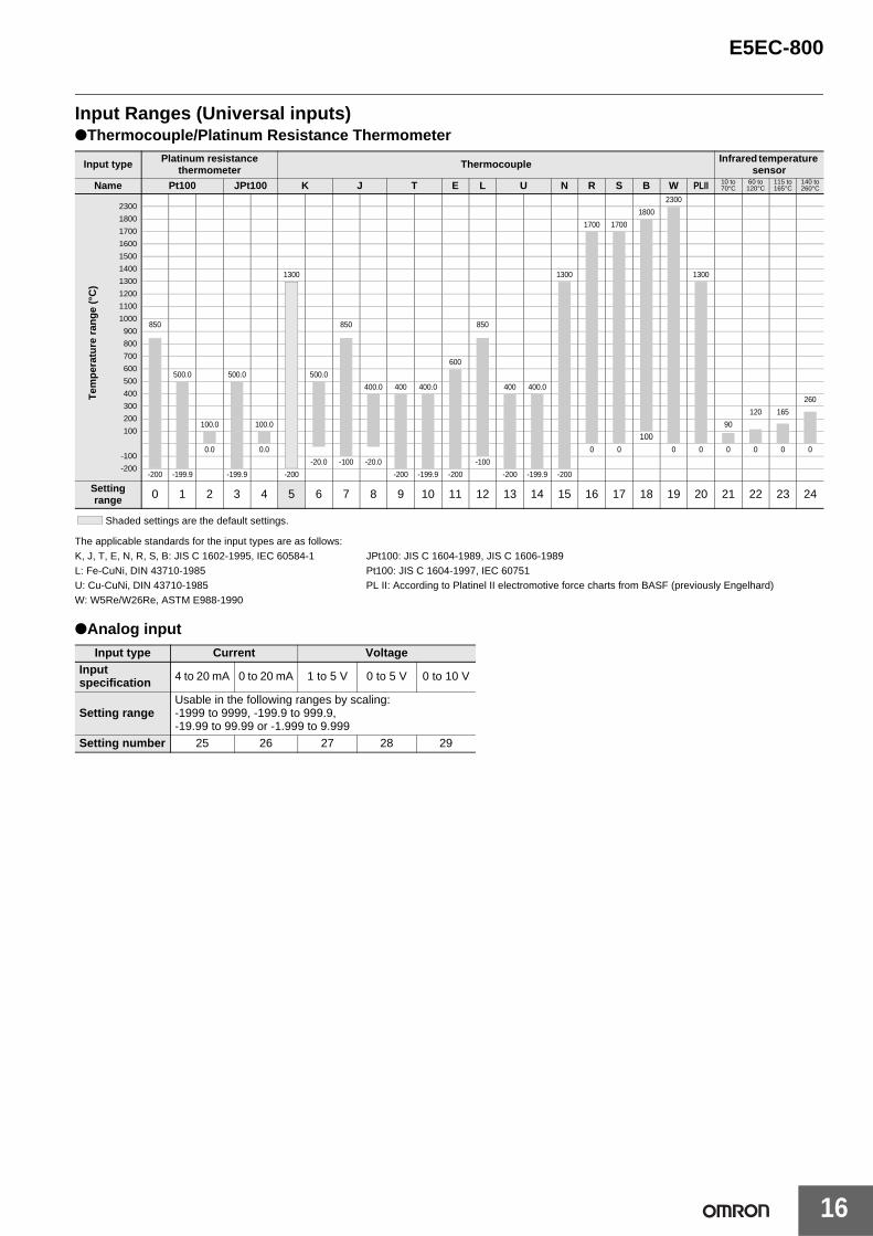
Input Ranges (Universal inputs)●Thermocouple/Platinum Resistance Thermometer
Shaded settings are the default settings.
The applicable standards for the input types are as follows:K, J, T, E, N, R, S, B: JIS C 1602-1995, IEC 60584-1 JPt100: JIS C 1604-1989, JIS C 1606-1989L: Fe-CuNi, DIN 43710-1985 Pt100: JIS C 1604-1997, IEC 60751U: Cu-CuNi, DIN 43710-1985 PL II: According to Platinel II electromotive force charts from BASF (previously Engelhard)W: W5Re/W26Re, ASTM E988-1990
●Analog input
Input type Platinum resistance thermometer Thermocouple Infrared temperature
sensor
Name Pt100 JPt100 K J T E L U N R S B W PLII 10 to 70°C
60 to 120°C
115 to 165°C
140 to 260°C
2300
1800
1700
1600
1500
1400
1300
1200
1100
1000
900
800
700
600
500
400
300
200
100
-100
-200
2300
1800
1700 1700
1300 1300 1300
850 850 850
600
500.0 500.0 500.0
400.0 400 400.0 400 400.0
260
120 165
100.0 100.0 90
1000.0 0.0 0 0 0 0 0 0 0 0
-20.0 -100 -20.0 -100
-200 -199.9 -199.9 -200 -200 -199.9 -200 -200 -199.9 -200
Setting range 0 1 2 3 4 5 6 7 8 9 10 11 12 13 14 15 16 17 18 19 20 21 22 23 24
Input type Current VoltageInput specification 4 to 20 mA 0 to 20 mA 1 to 5 V 0 to 5 V 0 to 10 V
Setting rangeUsable in the following ranges by scaling:-1999 to 9999, -199.9 to 999.9, -19.99 to 99.99 or -1.999 to 9.999
Setting number 25 26 27 28 29
Tem
per
atu
re r
ang
e (°
C)
E5EC-800
17
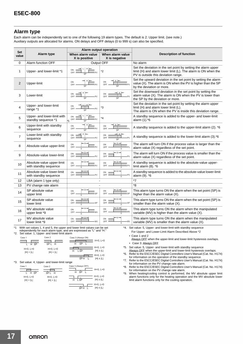
Alarm typeEach alarm can be independently set to one of the following 19 alarm types. The default is 2: Upper limit. (see note.)Auxiliary outputs are allocated for alarms. ON delays and OFF delays (0 to 999 s) can also be specified.
*1 With set values 1, 4 and 5, the upper and lower limit values can be set ndependently for each alarm type, and are expressed as “L” and “H.”
*2. Set value: 1, Upper- and lower-limit alarm
*3. Set value: 4, Upper- and lower-limit range
*4. Set value: 5, Upper- and lower-limit with standby sequenceFor Upper- and Lower-Limit Alarm Described Above *2
• Case 1 and 2Always OFF when the upper-limit and lower-limit hysteresis overlaps.
• Case 3: Always OFF*5. Set value: 5, Upper- and lower-limit with standby sequence
Always OFF when the upper-limit and lower-limit hysteresis overlaps.*6. Refer to the E5CC/E5EC Digital Controllers User's Manual (Cat. No. H174)
for information on the operation of the standby sequence.*7. Refer to the E5CC/E5EC Digital Controllers User's Manual (Cat. No. H174)
for information on the PV change rate alarm.*8. Refer to the E5CC/E5EC Digital Controllers User's Manual (Cat. No. H174)
for information on the PV change rate alarm.*9. When heating/cooling control is performed, the MV absolute upper limit
alarm functions only for the heating operation and the MV absolute lowerlimit alarm functions only for the cooling operation.
Setvalue Alarm type
Alarm output operationDescription of functionWhen alarm value
X is positiveWhen alarm value
X is negative0 Alarm function OFF Output OFF No alarm
1 Upper- and lower-limit *1 *2Set the deviation in the set point by setting the alarm upper limit (H) and alarm lower limit (L). The alarm is ON when the PV is outside this deviation range.
2 Upper-limitSet the upward deviation in the set point by setting the alarm value (X). The alarm is ON when the PV is higher than the SP by the deviation or more.
3 Lower-limitSet the downward deviation in the set point by setting the alarm value (X). The alarm is ON when the PV is lower than the SP by the deviation or more.
4 Upper- and lower-limit range *1
*3Set the deviation in the set point by setting the alarm upper limit (H) and alarm lower limit (L).The alarm is ON when the PV is inside this deviation range.
5 Upper- and lower-limit with standby sequence *1
*4A standby sequence is added to the upper- and lower-limit alarm (1).*6
6 Upper-limit with standby sequence A standby sequence is added to the upper-limit alarm (2). *6
7 Lower-limit with standby sequence A standby sequence is added to the lower-limit alarm (3).*6
8 Absolute-value upper-limit The alarm will turn ON if the process value is larger than the alarm value (X) regardless of the set point.
9 Absolute-value lower-limit The alarm will turn ON if the process value is smaller than the alarm value (X) regardless of the set point.
10 Absolute-value upper-limit with standby sequence
A standby sequence is added to the absolute-value upper-limit alarm (8). *6
11 Absolute-value lower-limit with standby sequence
A standby sequence is added to the absolute-value lower-limit alarm (9). *6
12 LBA (alarm 1 type only) - *713 PV change rate alarm - *8
14 SP absolute value upper limit
This alarm type turns ON the alarm when the set point (SP) is higher than the alarm value (X).
15 SP absolute value lower limit
This alarm type turns ON the alarm when the set point (SP) is smaller than the alarm value (X).
16 MV absolute value upper limit *9
This alarm type turns ON the alarm when the manipulated variable (MV) is higher than the alarm value (X).
17 MV absolute value lower limit *9
This alarm type turns ON the alarm when the manipulated variable (MV) is smaller than the alarm value (X).
ONOFF PV
SP
L H
SP
XONOFF PV
SP
XONOFF PV
SP
XONOFF PV
SP
XONOFF PV
SP
L HONOFF PV
SP
L HONOFF PV
*5
SP
XONOFF PV
SP
XONOFF PV
SP
XONOFF PV
SP
XONOFF PV
0
XONOFF PV
0
XONOFF PV
0
XONOFF PV
0
XONOFF PV
0
XONOFF PV
0
XONOFF PV
0
XONOFF PV
0
XONOFF PV
0
XONOFF SP
0
XONOFF SP
0
XONOFF SP
0
XONOFF SP
0
XONOFF MV 0
XONOFF MV
0
XONOFF MV
0
XONOFF MV
L H SP
Case 1
L HSP
Case 2
LH SP
LH SP
LHSP
Case 3 (Always ON)H<0, L<0
H<0, L>0|H| ≥ |L|
H>0, L<0|H| ≤ |L|
H<0, L>0|H| < |L|
H>0, L<0|H| > |L|
L H SP
Case 1
L HSP
Case 2
LH SP
L
L
H SP
HSP
Case 3 (Always OFF)
H<0, L>0|H| < |L|
H>0, L<0|H| > |L|
H<0, L<0
H<0, L>0|H| ≥ |L|
H>0, L<0|H| ≤ |L|
E5EC-800
18
Characteristics
*1. The indication accuracy of K thermocouples in the -200 to 1300°C range, T and N thermocouples at a temperature of -100°C max., and U and L thermocouples atany temperatures is ±2°C ±1 digit max. The indication accuracy of the B thermocouple at a temperature of 400°C max.is not specified. The indication accuracy of B thermocouples in the 400 to 800°C range is ±3°C max. The indication accuracy of the R and S thermocouples at atemperature of 200°C max. is ±3°C ±1 digit max. The indication accuracy of W thermocouples is ±0.3 of PV or ±3°C, whichever is greater, ±1 digit max. Theindication accuracy of PL II thermocouples is ±0.3 of PV or ±2°C, whichever is greater, ±1 digit max.
*2. Ambient temperature: -10°C to 23°C to 55°C, Voltage range: -15% to 10% of rated voltage*3. K thermocouple at -100°C max.: ±10°C max.*4. “EU” stands for Engineering Unit and is used as the unit after scaling. For a temperature sensor, the EU is °C or °F.*5. The unit is determined by the setting of the Integral/Derivative Time Unit parameter.*6. Refer to information on maritime standards in Shipping Standards on page 31 for compliance with Lloyd's Standards.
Indication accuracy(at the ambient temperature of 23°C)
Thermocouple: (±0.3% of indicated value or ±1°C, whichever is greater) ±1 digit max. *1Platinum resistance thermometer: (±0.2% of indicated value or ±0.8°C, whichever is greater) ±1 digitAnalog input: ±0.2% FS ±1 digit max.CT input: ±5% FS ±1 digit max.
Influence of temperature *2Thermocouple input (R, S, B, W, PL II): (±1% of PV or ±10°C, whichever is greater) ±1 digit max.Other thermocouple input: (±1% of PV or ±4°C, whichever is greater) ±1 digit max. *3Platinum resistance thermometer: (±1% of PV or ±2°C, whichever is greater) ±1 digit max.Analog input: (±1%FS) ±1 digit max.CT input: (±5% FS) ±1 digit max.
Influence of voltage *2
Input sampling period 50ms
Hysteresis Temperature input: 0.1 to 999.9°C or °F (in units of 0.1°C or°F) *4Analog input: 0.01% to 99.99% FS (in units of 0.01% FS)
Proportional band (P) Temperature input: 0.1 to 999.9°C or °F (in units of 0.1°C or °F) *4Analog input: 0.1 to 999.9% FS (in units of 0.1% FS)
Integral time (I) 0 to 9999 s (in units of 1 s), 0.0 to 999.9 s (in units of 0.1 s) *5Derivative time (D) 0 to 9999 s (in units of 1 s), 0.0 to 999.9 s (in units of 0.1 s) *5
Proportional band (P) for cooling Temperature input: 0.1 to 999.9°C or °F (in units of 0.1°C or °F) *4Analog input: 0.1 to 999.9% FS (in units of 0.1% FS)
Integral time (I) for cooling 0 to 9999 s (in units of 1 s), 0.0 to 999.9 s (in units of 0.1 s) *5Derivative time (D) for cooling 0 to 9999 s (in units of 1 s), 0.0 to 999.9 s (in units of 0.1 s) *5Control period 0.1, 0.2, 0.5, 1 to 99 s (in units of 1 s)Manual reset value 0.0 to 100.0% (in units of 0.1%)Alarm setting range -1999 to 9999 (decimal point position depends on input type)
Affect of signal source resistance Thermocouple: 0.1°C/Ω max. (100 Ω max.)Platinum resistance thermometer: 0.1°C/Ω max. (10 Ω max.)
Insulation resistance 20 MΩ min. (at 500 VDC)Dielectric strength 2,300 VAC, 50 or 60 Hz for 1 min (between terminals with different charge)
Vibrationresistance 10 to 55 Hz, 20 m/s2 for 10 min each in X, Y, and Z directionsMalfunction 10 to 55 Hz, 20 m/s2 for 2 hrs each in X, Y, and Z directions
Destructionresistance 100 m/s2, 3 times each in X, Y, and Z directionsMalfunction 300 m/s2, 3 times each in X, Y, and Z directions
Weight Controller: Approx. 210 g, Mounting Bracket: Approx. 4 g × 2Degree of protection Front panel: IP66, Rear case: IP20, Terminals: IP00Memory protection Non-volatile memory (number of writes: 1,000,000 times)
StandardsApproved standards UL 61010-1, CSA C22.2 No. 611010-1 (evaluated by UL)Conformed standards EN 61010-1 (IEC 61010-1): Pollution level 2, overcurrent category II, Lloyd's standards *6
EMC
EMI EN61326Radiated Interference Electromagnetic Field Strength: EN 55011 Group 1, class ANoise Terminal Voltage: EN 55011 Group 1, class AEMS: EN 61326ESD Immunity: EN 61000-4-2Electromagnetic Field Immunity: EN 61000-4-3Burst Noise Immunity: EN 61000-4-4Conducted Disturbance Immunity: EN 61000-4-6Surge Immunity: EN 61000-4-5Voltage Dip/Interrupting Immunity: EN 61000-4-11
E5EC-800
19
Communications Specifications
* The baud rate, data bit length, stop bit length, and vertical parity can be in-dividually set using the Communications Setting Level.
Current Transformer (Order Separately) Ratings
Heater Burnout Alarms and SSR Failure Alarms
*1. For heater burnout alarms, the heater current will be measured when thecontrol output is ON, and the output will turn ON if the heater current islower than the set value (i.e., heater burnout detection current value).
*2. For SSR failure alarms, the heater current will be measured when thecontrol output is OFF, and the output will turn ON if the heater current ishigher than the set value (i.e., SSR failure detection current value).
*3. The value is 30 ms for a control period of 0.1 s or 0.2 s.*4. The value is 35 ms for a control period of 0.1 s or 0.2 s.
Transmission line connection method RS-485: Multipoint
Communications RS-485 (two-wire, half duplex)Synchronization method Start-stop synchronization
Protocol CompoWay/F, or ModbusBaud rate 19200, 38400, or 57600 bpsTransmissioncode ASCII
Data bit length* 7 or 8 bitsStop bit length* 1 or 2 bits
Error detectionVertical parity (none, even, odd)Block check character (BCC) withCompoWay/F or CRC-16 Modbus
Flow control NoneInterface RS-485Retry function NoneCommunications buffer 217 bytes
Communications response wait time
0 to 99 msDefault: 20 ms
Dielectric strength 1,000 VAC for 1 minVibration resistance 50 Hz, 98 m/s2
Weight E54-CT1: Approx. 11.5 g, E54-CT3: Approx. 50 g
Accessories(E54-CT3 only)
Armatures (2)Plugs (2)
CT input (for heater current detection)
Models with detection for singlephase heaters: One inputModels with detection for singlephase or three-phase heaters: Two inputs
Maximum heater current 50 A AC
Input current indica-tion accuracy ±5% FS ±1 digit max.
Heater burnout alarm setting range *1
0.1 to 49.9 A (in units of 0.1 A)Minimum detection ON time: 100 ms *3
SSR failure alarm setting range *2
0.1 to 49.9 A (in units of 0.1 A)Minimum detection OFF time: 100 ms *4
E5EC-800
20
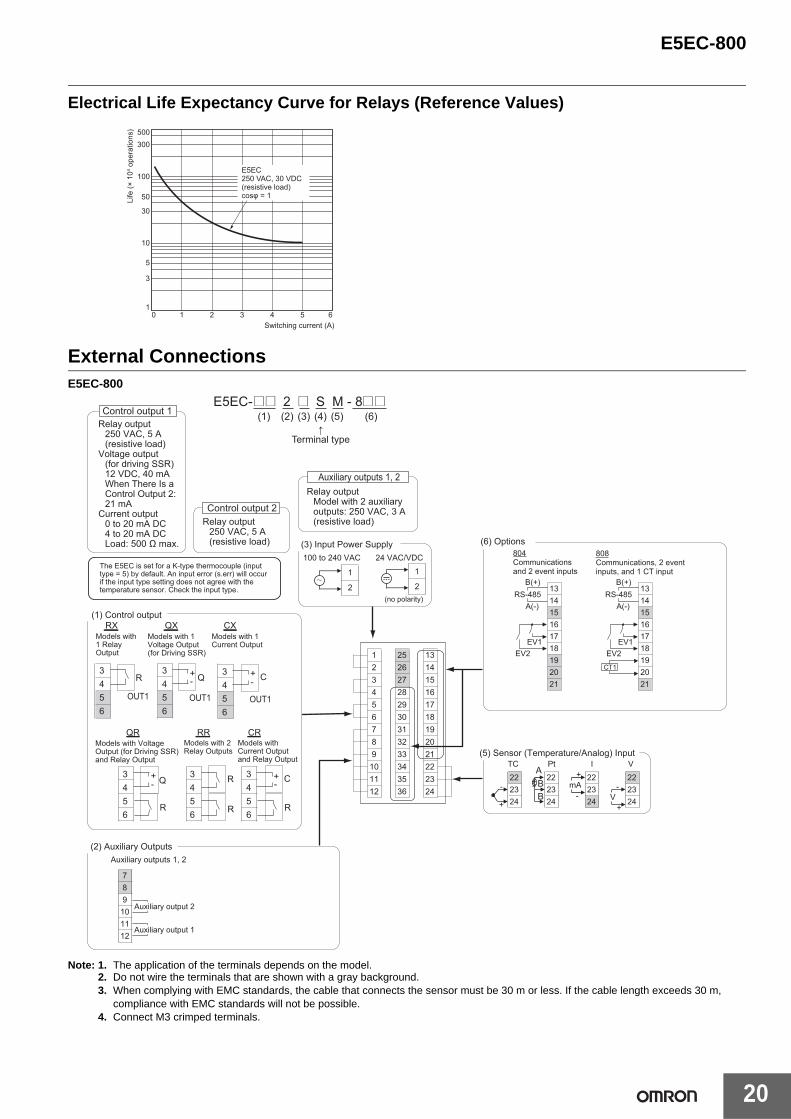
Electrical Life Expectancy Curve for Relays (Reference Values)
External ConnectionsE5EC-800
Note: 1. The application of the terminals depends on the model.2. Do not wire the terminals that are shown with a gray background.3. When complying with EMC standards, the cable that connects the sensor must be 30 m or less. If the cable length exceeds 30 m,
compliance with EMC standards will not be possible.4. Connect M3 crimped terminals.
500300
100
50
30
10
5
3
10 1 2 3 4 5 6
Switching current (A)
E5EC250 VAC, 30 VDC(resistive load)cosφ = 1Li
fe (×
104 o
pera
tions
)
The E5EC is set for a K-type thermocouple (input type = 5) by default. An input error (s.err) will occur if the input type setting does not agree with the temperature sensor. Check the input type.
Relay output250 VAC, 5 A(resistive load)
Voltage output (for driving SSR)12 VDC, 40 mAWhen There Is a Control Output 2:21 mA
Current output0 to 20 mA DC4 to 20 mA DCLoad: 500 Ω max.
2324
1112
3536
19202122
910
31323334
225
78
1756
2930
34
262728
1 13141516
18
2
1
2
100 to 240 VAC
1
24 VAC/VDC
V
- 23V 24
+
22
TC
22+
-mA-
+
2322
2324
Pt I
24
222324
ABB
78
1112
Auxiliary outputs 1, 2
910
Auxiliary output 1
Auxiliary output 2
192021
131415161718
808Communications, 2 event inputs, and 1 CT input
804Communications and 2 event inputs
192021
131415
1718
16
EV1EV2
EV1EV2
B(+)
A(-)RS-485
B(+)
A(-)RS-485
CT1
↑Terminal type
Auxiliary outputs 1, 2
Control output 2
Control output 1
Relay outputModel with 2 auxiliary outputs: 250 VAC, 3 A (resistive load)Relay output
250 VAC, 5 A(resistive load)
+
++
-+
- -
-
(1) Control output
Models with 1 Relay Output
Models with 1 Voltage Output (for Driving SSR)
Models with Voltage Output (for Driving SSR) and Relay Output
Models with 2 Relay Outputs
Models with Current Outputand Relay Output
Models with 1 Current Output
3456
3456
3456
3456
3456
3456
RX
R
R
R
R
Q
Q
OUT1OUT1OUT1
C
C
QR RR CR
QX CX
R
(2) Auxiliary Outputs
(3) Input Power Supply (6) Options
(5) Sensor (Temperature/Analog) Input
(no polarity)
E5EC-@@ 2 @ S M - 8@@ (1) (2) (3) (4) (5) (6)
E5EC-800
21
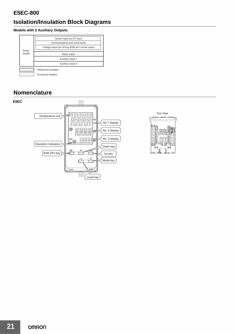
Isolation/Insulation Block DiagramsModels with 2 Auxiliary Outputs
Nomenclature
Communications and event inputs
Sensor input and CT input
Voltage output (for driving SSR) and current output
Relay output
Auxiliary output 1
Auxiliary output 2
: Reinforced insulation
: Functional isolation
Power Supply
E5EC
Top ViewTemperature unit
Operation indicators
Shift (PF) key
No.1 display
No. 2 display
No. 3 display
Down key
Up key
Mode key
Level key
E5EC-800
22
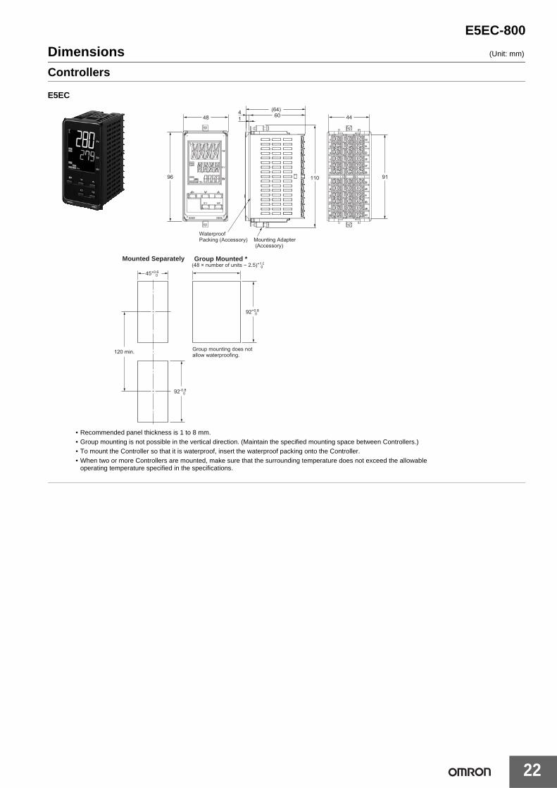
Dimensions (Unit: mm)
Controllers
14
Mounting Adapter (Accessory)
Waterproof Packing (Accessory)
96
48 60 44
91110
(64)
E5EC
92-0.8 0
92+0.8 0
45+0.6 0
120 min.
(48 × number of units − 2.5)+1.0 0
Group mounting does not allow waterproofing.
Mounted Separately Group Mounted *
• Recommended panel thickness is 1 to 8 mm.• Group mounting is not possible in the vertical direction. (Maintain the specified mounting space between Controllers.)• To mount the Controller so that it is waterproof, insert the waterproof packing onto the Controller.• When two or more Controllers are mounted, make sure that the surrounding temperature does not exceed the allowable
operating temperature specified in the specifications.
E5EC-800
23
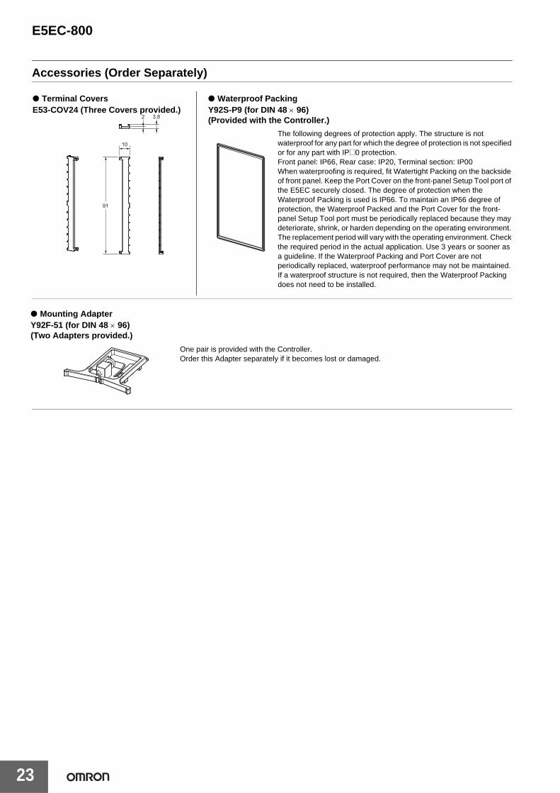
Accessories (Order Separately)
10
91
2 3.8
● Terminal CoversE53-COV24 (Three Covers provided.)
● Waterproof PackingY92S-P9 (for DIN 48 × 96)(Provided with the Controller.)
The following degrees of protection apply. The structure is not waterproof for any part for which the degree of protection is not specified or for any part with IP@0 protection.Front panel: IP66, Rear case: IP20, Terminal section: IP00When waterproofing is required, fit Watertight Packing on the backside of front panel. Keep the Port Cover on the front-panel Setup Tool port of the E5EC securely closed. The degree of protection when the Waterproof Packing is used is IP66. To maintain an IP66 degree of protection, the Waterproof Packed and the Port Cover for the front-panel Setup Tool port must be periodically replaced because they may deteriorate, shrink, or harden depending on the operating environment. The replacement period will vary with the operating environment. Check the required period in the actual application. Use 3 years or sooner as a guideline. If the Waterproof Packing and Port Cover are not periodically replaced, waterproof performance may not be maintained. If a waterproof structure is not required, then the Waterproof Packing does not need to be installed.
● Mounting AdapterY92F-51 (for DIN 48 × 96)(Two Adapters provided.)
One pair is provided with the Controller.Order this Adapter separately if it becomes lost or damaged.

E5EC-800
24
● Current Transformers
E54-CT3 Accessory• Armature
30
21
155.8 dia.
25 3
40
10.5
2.8
7.5
10
Two, 3.5 dia.
40 × 40
30
12 dia.9
2.36 dia.
15
30
Two, M3 (depth: 4)
Approx. 3 dia.
18
(22)
Approx. 6 dia.
PlugArmature
Lead
E54-CT1
E54-CT3
Connection Example
• Plug
Thru-current (Io) vs. Output Voltage (Eo)(Reference Values)E54-CT1Maximum continuous heater current: 50 A (50/60 Hz)Number of windings: 400±2Winding resistance: 18±2 Ω
Thru-current (Io) A (r.m.s.)
1 10 100mA 1 10 100 1,000A
100V Frequency: 50 Hz
Distortion factor 10%
3%1%
100Ω
RL=10Ω
∞10
1
100mV
10
1
100μV
10
1kΩ
Out
put v
olta
ge (E
o) V
(r.m
.s.)
Thru-current (Io) vs. Output Voltage (Eo)(Reference Values)E54-CT3Maximum continuous heater current: 120 A (50/60 Hz)(Maximum continuous heater current for an OMRON Digital Temperature Controller is 50 A.)Number of windings: 400±2Winding resistance: 8±0.8 Ω
Thru-current (Io) A (r.m.s.)
1 10 100mA 1 10 100 1,000A
100V Frequency: 50 HzDistortion factor 10%
3%1%
1kΩ
100Ω50Ω
RL=10Ω
500Ω
∞10
1
100mV
10
1
100μV
10
Out
put v
olta
ge (E
o) V
(r.m
.s.)
E5CC/E5EC-800
25
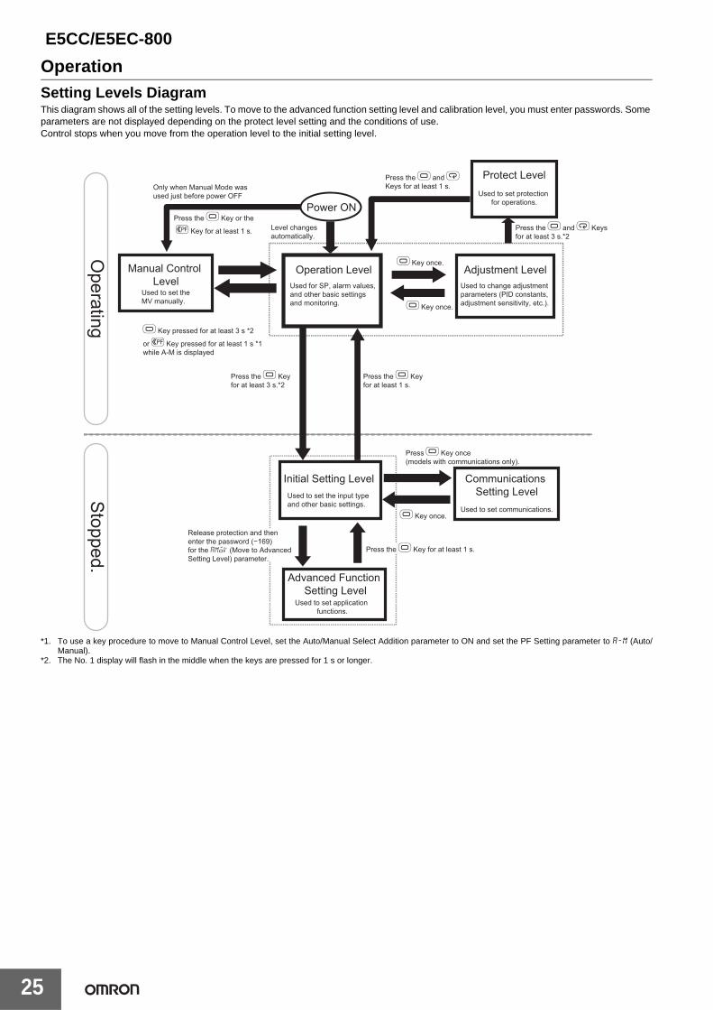
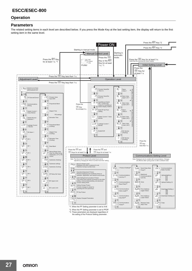
OperationSetting Levels DiagramThis diagram shows all of the setting levels. To move to the advanced function setting level and calibration level, you must enter passwords. Some parameters are not displayed depending on the protect level setting and the conditions of use.Control stops when you move from the operation level to the initial setting level.
*1. To use a key procedure to move to Manual Control Level, set the Auto/Manual Select Addition parameter to ON and set the PF Setting parameter to a-m (Auto/Manual).
*2. The No. 1 display will flash in the middle when the keys are pressed for 1 s or longer.
Press O Key once (models with communications only).
Communications Setting Level
Advanced Function Setting Level
Power ON
Used to set application functions.
Initial Setting Level
Operation Level
Used to set the input type and other basic settings.
Used to set communications.
Used for SP, alarm values, and other basic settings and monitoring.
Used to change adjustment parameters (PID constants, adjustment sensitivity, etc.).
Used to set protection for operations.
Press the O Key for at least 1 s.
Press the O and M Keys for at least 1 s.
Press the O and M Keys for at least 3 s.*2
Press the O Key for at least 3 s.*2
Press the O Key or the
S Key for at least 1 s.
Only when Manual Mode was used just before power OFF
Level changes automatically.
Protect Level
Manual Control Level
Used to set the MV manually.
O Key once.
O Key once.
O Key once.
Press the O Key for at least 1 s.
Release protection and then enter the password (−169) for the amoV (Move to Advanced Setting Level) parameter.
O Key pressed for at least 3 s *2
or S Key pressed for at least 1 s *1 while A-M is displayed
Adjustment Level
Stopped.
Operating
E5CC/E5EC-800
26
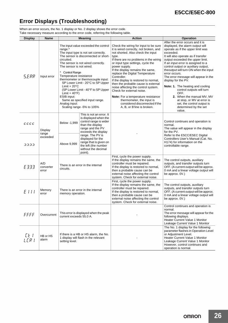
Error Displays (Troubleshooting)When an error occurs, the No. 1 display or No. 2 display shows the error code. Take necessary measure according to the error code, referring the following table.
Display Name Meaning Action Operation
s.err Input error
The input value exceeded the control range.*The input type is not set correctly.The sensor is disconnected or short-circuited.The sensor is not wired correctly.The sensor is not wired.
* Control RangeTemperature resistance thermometer or thermocouple input:
SP Lower Limit - 20°C to SP Upper Limit + 20°C (SP Lower Limit - 40°F to SP Upper Limit + 40°F)
ESIB input: Same as specified input range.
Analog input: Scaling range -5% to 105%
Check the wiring for input to be sure it is wired correctly, not broken, and not shorted. Also check the input type.If there are no problems in the wiring or input type settings, cycle the power supply.If the display remains the same, replace the Digital Temperature Controller.If the display is restored to normal, then the probable cause is external noise affecting the control system. Check for external noise.
Note: For a temperature resistance thermometer, the input is considered disconnected if the A, B, or B’line is broken.
After the error occurs and it is displayed, the alarm output will operate as if the upper limit was exceeded.It will also operate as if transfer output exceeded the upper limit.If an input error is assigned to a control output or auxiliary output, theoutput will turn ON when the input error occurs.The error message will appear in the display for the PV.
Note: 1. The heating and cooling control outputs will turn OFF.
2. When the manual MV, MV at stop, or MV at error is set, the control output is determined by the set value.
[[[[
Display range exceeded
Below -1,999
This is not an error. It is displayed when the control range is wider than the display range and the PV exceeds the display range. The PV is displayed for the range that is given on the left (the number without the decimal point).
-
Control continues and operation is normal.The value will appear in the display for the PV.Refer to the E5CC/E5EC Digital Controllers User’s Manual (Cat. No. H174) for information on the controllable range.]]]] Above 9,999
e333A/D converter error
There is an error in the internal circuits.
First, cycle the power supply.If the display remains the same, the controller must be repaired. If the display is restored to normal, then a probable cause can be external noise affecting the control system. Check for external noise.
The control outputs, auxiliary outputs, and transfer outputs turn OFF. (A current output will be approx. 0 mA and a linear voltage output will be approx. 0V.)
e111Memory error
There is an error in the internal memory operation.
First, cycle the power supply.If the display remains the same, the controller must be repaired. If the display is restored to normal, then a probable cause can be external noise affecting the control system. Check for external noise.
The control outputs, auxiliary outputs, and transfer outputs turn OFF. (A current output will be approx. 0 mA and a linear voltage output will be approx. 0V.)
ffff Overcurrent This error is displayed when the peak current exceeds 55.0 A. -
Control continues and operation is normal.The error message will appear for the following displays.Heater Current Value 1 MonitorLeakage Current Value 1 Monitor
ct1
lcr1
HB or HS alarm
If there is a HB or HS alarm, the No. 1 display will flash in the relevant setting level.
-
The No. 1 display for the following parameter flashes in Operation Level or Adjustment Level.Heater Current Value 1 MonitorLeakage Current Value 1 MonitorHowever, control continues and operation is normal.
E5CC/E5EC-800
27
Operation
M
M
M
M
M
M
M
M
M
M
M
M
M
M
M
M
M
M
M
M
M
M
M
M
M
M
M
M
M
M
M
M
M
M
M
M
M
M
M
M
M
M
M
250
C
250
l.adj
ins0.0
c-p8.0
c-i233
c-d40
M
M
M
p8.0
i233
d40
c-db0.0
of-r50.0
hys1.0
chys1.0
pmov0
oapt0
icpt1
wtptoff
pfptoff
M
chgpoff
M
M
sprtoff
ol-h100.0
ol-l0.0
atoff
cmwtoff
ct10.0
M
hb10.0
lcr10
hs150.0
sp-00
sp-10
sp-20
sp-30
sp-40
sp-50
sp-60
sp-70
M
sp-30
r-srun
al-10
al1h0
al1l0
al-20
al2h0
al2l0
M
o0.0
c-o0.0
250
a-m
m-sp0
ct-10.0
lcr10.0
PID Control only
Press the S Key for at least 1 s. *1
Press the O
Key or the S Key for at least 1 s. *1
Operation Level
Power ONStarting in manual mode.
Adjustment LevelPress the O Key less than 1 s.
Press the O Key less than 1 s.
PV/MV
Starting in automatic mode.
Adjustment Level DisplayDisplayed only once when entering adjustment level.
Manual Control Level
Press the S Key *2
Press the S Key *2
Press the
O Key for at least 3 s.
Press the O and
M Keys for at least 3 s.
Proportional Band (Cooling)
Protect LevelNote: The time ta ken to move to the protect level can be
adjusted by changing the "Move to protect level time" setting.
*1. When the PF Setting parameter is set to A-M.*2. When the PF Setting parameter is set to PFDP.*3. These parameters are displayed regardless of
the setting of the Protocol Setting parameter.
Move to Protect Level:
Operation/Adjustment Protect:
Initial Setting/Communications Protect:
Setting Change Protect:
Displayed only when a password is set.Restricts moving to protect level.
Restricts displaying and modifying menus in operation, adjustment, and manual control levels.
This protect level restricts movement to the initial setting, communicationssetting, and advanced function setting levels.
Protects changes to setups by operating the front panel keys.
PF Key Protect
AT Execute/Cancel
Communications Writing
Heater Current 1 Value Monitor
Leakage Current 1 Monitor
Heater Burnout Detection 1
HS Alarm 1
SP 0
SP 1
SP 2
SP 3
SP 4
SP 5
SP 6
SP 7
Integral Time (Cooling)
Derivative Time (Cooling)
Dead Band
Manual Reset Value Clear the offset during stabilization of P or PD control.
Hysteresis (Heating)
Hysteresis (Cooling)
MV Upper Limit
MV Lower Limit
Hysteresis settings
Process Value Input Shift
Process Value/Set Point (1)
Process Value/Set Point (2)
Auto/Manual SwitchPID 1 control only.Added for Auto/Manual Switch Display Addition.
Heater Current 1 Value Monitor
Leakage Current 1 Monitor
Multi-SP Set Point Setting
Alarm Value 1
Alarm Value Upper Limit 1
Alarm Value Lower Limit 1
Alarm Value 2
Alarm Value Upper Limit 2
Alarm Value Lower Limit 2
MV Monitor (Heating)
MV Monitor (Cooling)
Press the O and
M Keys for at least 1 s.
Proportional Band
Integral Time
Derivative Time
PID settings
SP Ramp Set Value
RUN/STOP
Display Changed Parameters
Set either of these param
eters.S
et either of these parameters.
Press the
O Key less than 1 s.
Communications Setting LevelNote: Displayed only for models with communications. Changes
are effective after cycling power or after a software reset.
M
M
M
len7
sbit2
prtyeven
Communications Data Length*3
Communications Stop Bits*3
Communications Parity*3
Initial Setting Level
Press the O Key for at least 3 s.
Press the O Key for at least 1 s.
Other than the Auto/Manual Switch display
M
M
M
M
M
Protocol Setting*3
Communications Unit No.*3
Communications Baud Rate*3
Send Data Wait Time*3
Maximum Communications Unit No.
Area
M
M
M
M
First Address Upper Word
First Address Lower Word
Receive Data Wait Time
Upload Setting 1
M
M
M
M
Upload Setting 13
Download Setting 1
Download Setting 13
Copy
M
⋅ ⋅ ⋅
⋅⋅ ⋅
⋅ ⋅
pselfins
u-no0
bps57.6
sdwt20
maxu0
adrh0
adrl0
rwat1000
area0
up130
dn 10
dn131000
copyoff
up 10
M
Communications Node Number
unit0
ParametersThe related setting items in each level are described below. If you press the Mode Key at the last setting item, the display will return to the first setting item in the same level.
E5CC/E5EC-800
28
M
M
M
M
M
M
M
M
M
M
M
M
M
M
M
M
M
M
M
M
M
M
M
M
M
M
M
M
M
M
M
M
M
M
M
M
M
M
M
M
M
M
M
M
M
M
M
M
M
M
M
M
M
M
M
M
M
M
M
M
M
M
S S S S
alt22
250
initoff
a1ltoff
a2ltoff
hsuon
hsloff
hsh0.1
pvrp20
hctmoff
mspuoff
sprum
resta
retoff
alh20.2
ev-1msp0
ev-2stop
ev-3none
ev-4none
o1st4-20
o2st4-20
amov0
sb1nn-o
sb2nn-o
hbuon
hbloff
hbh0.1
st-b15.0
alfa0.65
tidu1
inf0.0
mavoff
o-dpoff
prlt3
a1on0
a2on0
a1of0
a2of0
amadoff
manthold
mani0.0
cjcon
lba0
lbal8.0
lbab3.0
out1o
out2none
sub1alm1
sub2alm2
alma49
t-um
alspsp-m
pfshft
spd14
spd20
odslo
pvdpon
pvstoff
svstoff
d.ref0.25
ompw1.0
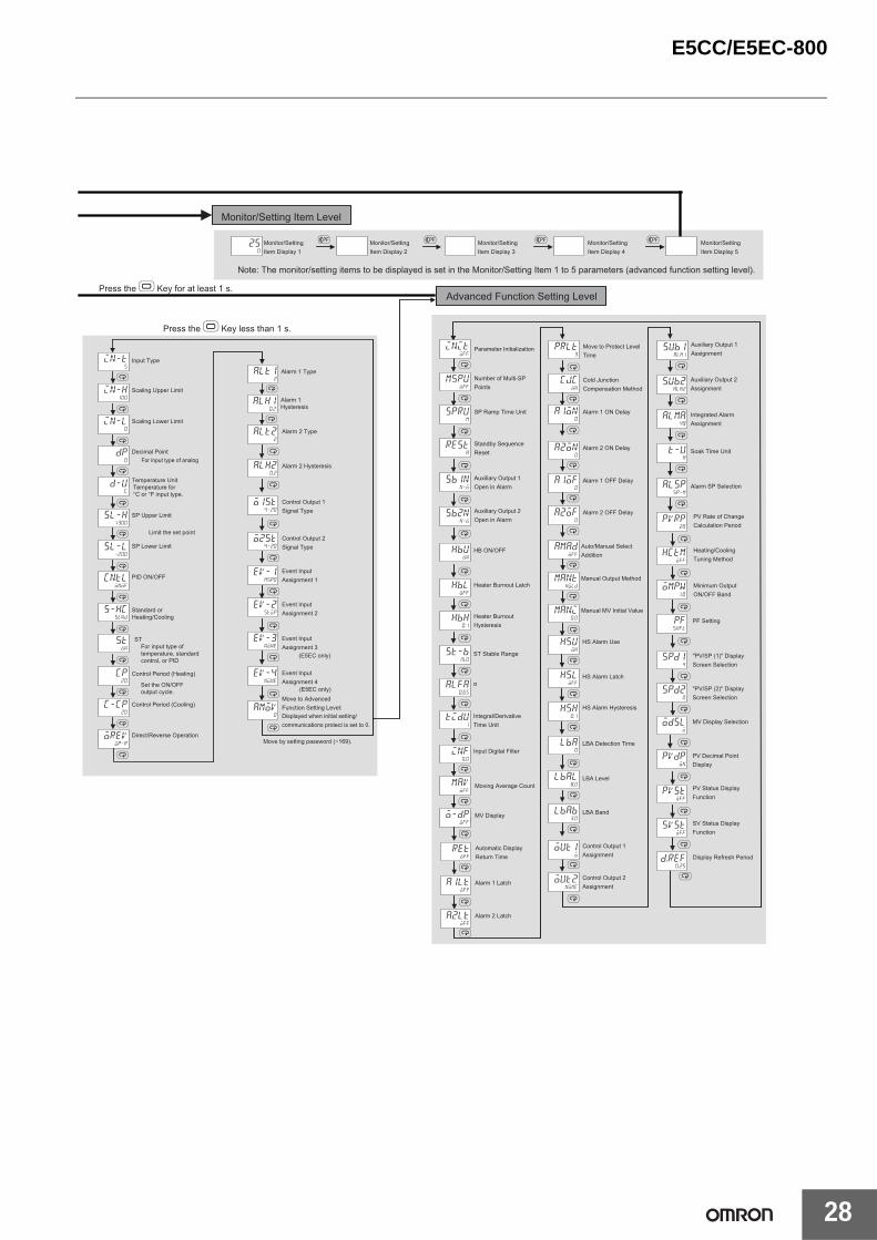
Press the O Key for at least 1 s.Advanced Function Setting Level
Alarm 1 Latch
Alarm 2 Latch
Move to Protect Level Time
HS Alarm Latch
HS Alarm Hysteresis
LBA Detection Time
LBA Level
LBA Band
Control Output 1 Assignment
Control Output 2 Assignment
HS Alarm Use
Parameter Initialization
Heater Burnout Latch
Number of Multi-SP Points
SP Ramp Time Unit
Standby Sequence Reset
Auxiliary Output 1 Open in Alarm
Auxiliary Output 2 Open in Alarm
Heater Burnout Hysteresis
HB ON/OFF
PF Setting
"PV/SP (1)" Display Screen Selection
MV Display Selection
PV Decimal Point Display
PV Status Display Function
SV Status Display Function
"PV/SP (2)" Display Screen Selection
Input Digital Filter
ST Stable Range
α
Integral/Derivative Time Unit
Alarm 1 ON Delay
Alarm 2 ON Delay
Alarm 1 OFF Delay
Alarm 2 OFF Delay
Auxiliary Output 1 Assignment
Auxiliary Output 2 Assignment
Soak Time Unit
Alarm SP Selection
Integrated Alarm Assignment
Moving Average Count
Auto/Manual Select Addition
Manual Output Method
Manual MV Initial Value
Monitor/Setting Item Display 1
Note: The monitor/setting items to be displayed is set in the Monitor/Setting Item 1 to 5 parameters (advanced function setting level).
Monitor/Setting Item Display 2
Monitor/Setting Item Display 3
Monitor/Setting Item Display 4
Monitor/Setting Item Display 5
Monitor/Setting Item Level
Alarm 2 Type
Move to Advanced Function Setting Level:Displayed when initial setting/communications protect is set to 0.
Move by setting password (−169).
Event Input Assignment 1
Event Input Assignment 2
Alarm 2 Hysteresis
Event Input Assignment 3
Event Input Assignment 4
Display Refresh Period
PV Rate of Change Calculation Period
Heating/Cooling Tuning Method
Minimum Output ON/OFF Band
Automatic Display Return Time
MV Display
Control Output 1 Signal Type
Control Output 2 Signal Type
(E5EC only)
(E5EC only)
Cold Junction Compensation Method
M
M
M
M
M
M
M
M
M
M
M
M
M
M
M
in-t5
in-h100
in-l0
dp0
d-uc
sl-h1300
sl-l-200
cntlonof
s-hcstnd
ston
cp20
c-cp20
orevor-r
alt12
alh10.2
Press the O Key less than 1 s.
ST
Input Type
Control Period (Heating)
Scaling Upper Limit
Scaling Lower Limit
Decimal Point
Temperature Unit
SP Upper Limit
SP Lower Limit
PID ON/OFF
Standard or Heating/Cooling
Control Period (Cooling)
Direct/Reverse Operation
For input type of analog
Limit the set point
For input type of temperature, standard control, or PID
Set the ON/OFF output cycle.
Temperature for °C or °F input type.
Alarm 1 Hysteresis
Alarm 1 Type
E5CC/E5EC-800
29
Safety Precautions● Be sure to read the precautions for all E5CC/E5EC-800 models in the website at: http://www.ia.omron.com/.
Do not touch the terminals while power is being supplied.Doing so may occasionally result in minor injury due to electric shock.
Electric shock may occur. Do not touch any cables or connectors with wet hands.
Electric shock, fire, or malfunction may occasionally occur. Do not allow metal objects, conductors, cuttings from installation work, or moisture to enter the Digital Temperature Controller or the Setup Tool port or ports. Attach the cover to the front-panel Setup Tool port whenever you are not using it to prevent foreign objects from entering the port.
Do not use the Digital Temperature Controller where subject to flammable or explosive gas. Otherwise, minor injury from explosion may occasionally occur.
Not doing so may occasionally result in fire. Do not allow dirt or other foreign objects to enter the Setup Tool port or ports, or between the pins on the connectors on the Setup Tool cable.
Minor electric shock or fire may occasionally occur. Do not use any cables that are damaged.
Never disassemble, modify, or repair the product or touch any of the internal parts. Minor electric shock, fire, or malfunction may occasionally occur.
CAUTION - Risk of Fire and Electric Shocka. This product is UL recognised as Open Type
Process Control Equipment. It must be mounted in an enclosure that does not allow fire to escape externally.
b. More than one disconnect switch may be required to de-energize the equipment before servicing the product.
c. Signal inputs are SELV, limited energy. *1d. Caution: To reduce the risk of fire or electric shock, do not
interconnect the outputs of different Class 2 circuits. *2
If the output relays are used past their life expectancy, contact fusing or burning may occasionally occur.Always consider the application conditions and use the output relays within their rated load and electrical life expectancy. The life expectancy of output relays varies considerably with the output load and switching conditions.
Tighten the terminal screws to the rated torque of between 0.43 and 0.58 N•m. Loose screws may occasionally result in fire.
Set the parameters of the product so that they are suitable for the system being controlled. If they are not suitable, unexpected operation may occasionally result in property damage or accidents.
A malfunction in the product may occasionally make control operations impossible or prevent alarm outputs, resulting in property damage. To maintain safety in the event of malfunction of the product, take appropriate safety measures, such as installing a monitoring device on a separate line.
*1. An SELV circuit is one separated from the power supply withdouble insulation or reinforced insulation, that does not exceed 30 V r.m.s. and 42.4 V peak or 60 VDC.
*2. A class 2 power supply is one tested and certified by UL as having the current and voltage of the secondary output restricted to specific levels.
CAUTION
E5CC/E5EC-800
30
Be sure to observe the following precautions to prevent malfunction or adverse affects on the performance or functionality of the product.Not doing so may occasionally result in faulty operation.1. This product is specifically designed for indoor use only.
Do not use this product in the following places:• Places directly subject to heat radiated from heating equipment.• Places subject to splashing liquid or oil atmosphere.• Places subject to direct sunlight.• Places subject to dust or corrosive gas (in particular, sulfide gas
and ammonia gas).• Places subject to intense temperature change.• Places subject to icing and condensation.• Places subject to vibration and large shocks.
2. Use and store the product within the rated ambient temperatureand humidity.Gang-mounting two or more Digital Temperature Controllers, or mounting Digital Temperature Controllers above each other may cause heat to build up inside the Digital Temperature Controllers, which will shorten their service life. In such a case, use forced cooling by fans or other means of air ventilation to cool down the Digital Temperature Controllers.
3. To allow heat to escape, do not block the area around the Digital Temperature Controller.Do not block the ventilation holes on the Digital Temperature Controller.
4. Be sure to wire properly with correct polarity of terminals.5. Use the specified size of crimp terminals for wiring (M3, width of
5.8 mm or less). For open-wired connections, use stranded or solid copper wires with a gauge of AWG24 to AWG18 (equal to a crosssectional area of 0.205 to 0.823 mm2). (The stripping length is 6 to 8 mm.) Up to two wires of the same size and type or two crimp terminals can be connected to one terminal. Do not connect more than two wires or more than two crimp terminals to the same terminal.
6. Do not wire the terminals that are not used.7. Use a commercial power supply for the power supply voltage input
to a Digital Temperature Controller with AC input specifications. Do not use the output from an inverter as the power supply. Depending on the output characteristics of the inverter, temperature increases in the Digital Temperature Controller may cause smoke or fire damage even if the inverter has a specified output frequency of 50/60 Hz.
8. To avoid inductive noise, keep the wiring for the product’s terminal block away from power cables carry high voltages or large currents. Also, do not wire power lines together with or parallel to product wiring. Using shielded cables and using separate conduits or ducts is recommended.Attach a surge suppressor or noise filter to peripheral devices that generate noise (in particular, motors, transformers, solenoids, magnetic coils, or other equipment that have an inductance component).When a noise filter is used at the power supply, first check the voltage or current, and attach the noise filter as close as possible to the product.Allow as much space as possible between the product and devices that generate powerful high frequencies (high-frequency welders, high-frequency sewing machines, etc.) or surge.
9. Use this product within the rated load and power supply.10.Make sure that the rated voltage is attained within two seconds of
turning ON the power using a switch or relay contact. If the voltage is applied gradually, the power may not be reset or output malfunctions may occur.
11.Make sure that the Digital Temperature Controller has 30 minutes or more to warm up after turning ON the power before starting actual control operations to ensure the correct temperature display.
12.When executing self-tuning, turn ON power to the load (e.g., heater) at the same time as or before supplying power to the product. If power is turned ON to the product before turning ON power to the load, self-tuning will not be performed properly and optimum control will not be achieved.
13.A switch or circuit breaker must be provided close to the product.The switch or circuit breaker must be within easy reach of the operator, and must be marked as a disconnecting means for this unit.
14.Use a soft and dry cloth to clean the product carefully. Do not use organic solvent, such as paint thinner, benzine or alcohol to clean the product.
15.Design the system (e.g., control panel) considering the 2 seconds of delay that the product's output to be set after power ON.
16.The output may turn OFF when you move to the initial setting level. Take this into consideration when performing control operations.
17.The number of non-volatile memory write operations is limited.Therefore, use RAM write mode when frequently overwriting data during communications or other operations.
18.Use suitable tools when taking the Digital Temperature Temperature Controller apart for disposal. Sharp parts inside the Digital Temperature Controller may cause injury.
19.Do not touch the external power supply terminals or other metal parts on the Digital Temperature Controller.
20.Do not exceed the communications distance that is given in the specifications. Use the specified communications cable.Refer to the E5CC/E5EC Digital Controllers User’s Manual (Cat. No. H174) for information on the communications distances and cables.
21.Do not bend the communications cables past their natural bending radius. Do not pull on the communications cables.
22.Connectors may be damaged if they are inserted with excessive force. When connecting a connector, always may sure that it is oriented correctly. Do not force the connector if it does not connect smoothly.
23.Do not exceed the communications distance that is given in the specifications. Use the specified communications cable.Refer to the E5CC/E5EC Digital Controllers User’s Manual (Cat. No. H174) for information on the communications distances and cables.
24.Do not bend the communications cables past their natural bending radius. Do not pull on the communications cables.
Precautions for Safe Use
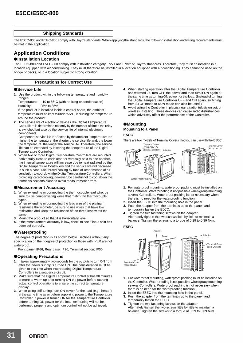
E5CC/E5EC-800
31
The E5CC-800 and E5EC-800 comply with Lloyd's standards. When applying the standards, the following installation and wiring requirements mustbe met in the application.
Application Conditions●Installation LocationThe E5CC-800 and E5EC-800 comply with installation category ENV1 and ENV2 of Lloyd's standards. Therefore, they must be installed in alocation equipped with air conditioning. They must therefore be installed in a location equipped with air conditioning. They cannot be used on thebridge or decks, or in a location subject to strong vibration.
●Service Life1. Use the product within the following temperature and humidity
ranges:Temperature: -10 to 55°C (with no icing or condensation)Humidity: 25% to 85%If the product is installed inside a control board, the ambient temperature must be kept to under 55°C, including the temperature around the product.
2. The service life of electronic devices like Digital Temperature Controllers is determined not only by the number of times the relay is switched but also by the service life of internal electronic components.Component service life is affected by the ambient temperature: the higher the temperature, the shorter the service life and, the lower the temperature, the longer the service life. Therefore, the service life can be extended by lowering the temperature of the Digital Temperature Controller.
3. When two or more Digital Temperature Controllers are mounted horizontally close to each other or vertically next to one another, the internal temperature will increase due to heat radiated by the Digital Temperature Controllers and the service life will decrease. In such a case, use forced cooling by fans or other means of air ventilation to cool down the Digital Temperature Controllers. When providing forced cooling, however, be careful not to cool down the terminals sections alone to avoid measurement errors.
●Measurement Accuracy1. When extending or connecting the thermocouple lead wire, be
sure to use compensating wires that match the thermocouple types.
2. When extending or connecting the lead wire of the platinum resistance thermometer, be sure to use wires that have low resistance and keep the resistance of the three lead wires the same.
3. Mount the product so that it is horizontally level.4. If the measurement accuracy is low, check to see if input shift has
been set correctly.
●WaterproofingThe degree of protection is as shown below. Sections without any specification on their degree of protection or those with IP@0 are not waterproof.
Front panel: IP66, Rear case: IP20, Terminal section: IP00
●Operating Precautions1. It takes approximately two seconds for the outputs to turn ON from
after the power supply is turned ON. Due consideration must be given to this time when incorporating Digital Temperature Controllers in a sequence circuit.
2. Make sure that the Digital Temperature Controller has 30 minutes or more to warm up after turning ON the power before starting actual control operations to ensure the correct temperature display.
3. When using self-tuning, turn ON power for the load (e.g., heater) at the same time as or before supplying power to the Temperature Controller. If power is turned ON for the Temperature Controller before turning ON power for the load, self-tuning will not be performed properly and optimum control will not be achieved.
4. When starting operation after the Digital Temperature Controller has warmed up, turn OFF the power and then turn it ON again at the same time as turning ON power for the load. (Instead of turning the Digital Temperature Controller OFF and ON again, switching from STOP mode to RUN mode can also be used.)
5. Avoid using the Controller in places near a radio, television set, or wireless installing. These devices can cause radio disturbances which adversely affect the performance of the Controller.
●MountingMounting to a Panel
E5CCThere are two models of Terminal Covers that you can use with the E5CC.
1. For waterproof mounting, waterproof packing must be installed on the Controller. Waterproofing is not possible when group mounting several Controllers. Waterproof packing is not necessary when there is no need for the waterproofing function.
2. Insert the E5CC into the mounting hole in the panel.3. Push the adapter from the terminals up to the panel, and
temporarily fasten the E5CC.4. Tighten the two fastening screws on the adapter.
Alternately tighten the two screws little by little to maintain a balance. Tighten the screws to a torque of 0.29 to 0.39 N•m.
E5EC
1. For waterproof mounting, waterproof packing must be installed on the Controller. Waterproofing is not possible when group mounting several Controllers. Waterproof packing is not necessary when there is no need for the waterproofing function.
2. Insert the E5EC into the mounting hole in the panel.3. Push the adapter from the terminals up to the panel, and
temporarily fasten the E5EC.4. Tighten the two fastening screws on the adapter.
Alternately tighten the two screws little by little to maintain a balance. Tighten the screws to a torque of 0.29 to 0.39 N•m.
Shipping Standards
Precautions for Correct Use
Panel
Water Proof Packing
Terminal Cover (E53-COV17)(Sold separately) Adapter
Terminal Cover (E53-COV23)
Adapter
AdapterPanel
Terminal Cover (E53-COV24)
Terminal Cover (E53-COV24)
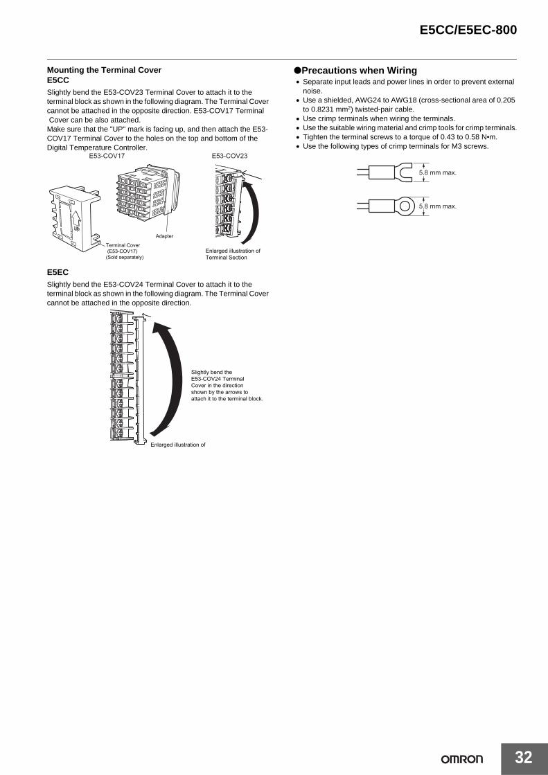
E5CC/E5EC-800
32
Mounting the Terminal CoverE5CCSlightly bend the E53-COV23 Terminal Cover to attach it to the terminal block as shown in the following diagram. The Terminal Cover cannot be attached in the opposite direction. E53-COV17 Terminal Cover can be also attached.Make sure that the "UP" mark is facing up, and then attach the E53-COV17 Terminal Cover to the holes on the top and bottom of the Digital Temperature Controller.
E5ECSlightly bend the E53-COV24 Terminal Cover to attach it to the terminal block as shown in the following diagram. The Terminal Cover cannot be attached in the opposite direction.
●Precautions when Wiring• Separate input leads and power lines in order to prevent external
noise.• Use a shielded, AWG24 to AWG18 (cross-sectional area of 0.205
to 0.8231 mm2) twisted-pair cable.• Use crimp terminals when wiring the terminals.• Use the suitable wiring material and crimp tools for crimp terminals.• Tighten the terminal screws to a torque of 0.43 to 0.58 N•m. • Use the following types of crimp terminals for M3 screws.
Adapter
Terminal Cover (E53-COV17)(Sold separately)
E53-COV17 E53-COV23
Enlarged illustration of Terminal Section
Enlarged illustration of
Slightly bend the E53-COV24 Terminal Cover in the direction shown by the arrows to attach it to the terminal block.
5.8 mm max.
5.8 mm max.
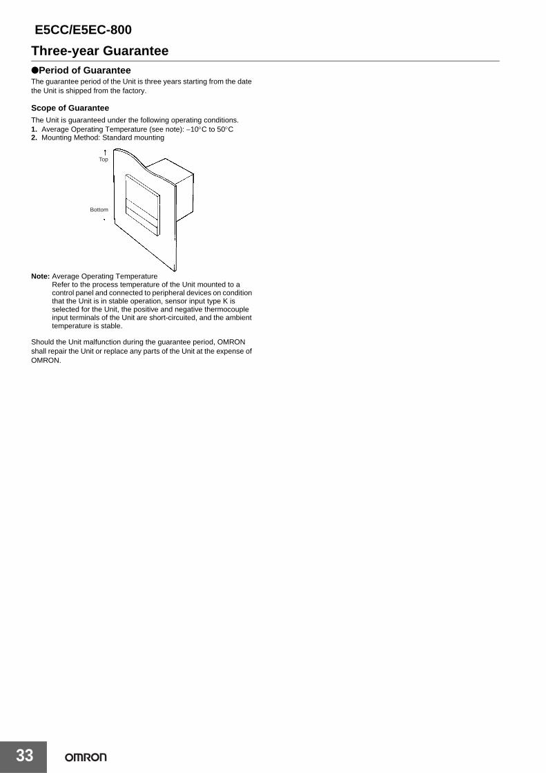
E5CC/E5EC-800
33
Three-year Guarantee●Period of GuaranteeThe guarantee period of the Unit is three years starting from the date the Unit is shipped from the factory.
Scope of GuaranteeThe Unit is guaranteed under the following operating conditions.1. Average Operating Temperature (see note): −10°C to 50°C2. Mounting Method: Standard mounting
Note: Average Operating TemperatureRefer to the process temperature of the Unit mounted to a control panel and connected to peripheral devices on condition that the Unit is in stable operation, sensor input type K is selected for the Unit, the positive and negative thermocouple input terminals of the Unit are short-circuited, and the ambient temperature is stable.
Should the Unit malfunction during the guarantee period, OMRON shall repair the Unit or replace any parts of the Unit at the expense of OMRON.
Top
Bottom

MEMO
34
Terms and Conditions of Sale1. Offer; Acceptance. These terms and conditions (these "Terms") are deemed
part of all quotes, agreements, purchase orders, acknowledgments, price lists,catalogs, manuals, brochures and other documents, whether electronic or inwriting, relating to the sale of products or services (collectively, the "Products")by Omron Electronics LLC and its subsidiary companies (“Omron”). Omronobjects to any terms or conditions proposed in Buyer’s purchase order or otherdocuments which are inconsistent with, or in addition to, these Terms.
2. Prices; Payment Terms. All prices stated are current, subject to change with-out notice by Omron. Omron reserves the right to increase or decrease priceson any unshipped portions of outstanding orders. Payments for Products aredue net 30 days unless otherwise stated in the invoice.
3. Discounts. Cash discounts, if any, will apply only on the net amount of invoicessent to Buyer after deducting transportation charges, taxes and duties, and willbe allowed only if (i) the invoice is paid according to Omron’s payment termsand (ii) Buyer has no past due amounts.
4. Interest. Omron, at its option, may charge Buyer 1-1/2% interest per month orthe maximum legal rate, whichever is less, on any balance not paid within thestated terms.
5. Orders. Omron will accept no order less than $200 net billing. 6. Governmental Approvals. Buyer shall be responsible for, and shall bear all
costs involved in, obtaining any government approvals required for the impor-tation or sale of the Products.
7. Taxes. All taxes, duties and other governmental charges (other than generalreal property and income taxes), including any interest or penalties thereon,imposed directly or indirectly on Omron or required to be collected directly orindirectly by Omron for the manufacture, production, sale, delivery, importa-tion, consumption or use of the Products sold hereunder (including customsduties and sales, excise, use, turnover and license taxes) shall be charged toand remitted by Buyer to Omron.
8. Financial. If the financial position of Buyer at any time becomes unsatisfactoryto Omron, Omron reserves the right to stop shipments or require satisfactorysecurity or payment in advance. If Buyer fails to make payment or otherwisecomply with these Terms or any related agreement, Omron may (without liabil-ity and in addition to other remedies) cancel any unshipped portion of Prod-ucts sold hereunder and stop any Products in transit until Buyer pays allamounts, including amounts payable hereunder, whether or not then due,which are owing to it by Buyer. Buyer shall in any event remain liable for allunpaid accounts.
9. Cancellation; Etc. Orders are not subject to rescheduling or cancellationunless Buyer indemnifies Omron against all related costs or expenses.
10. Force Majeure. Omron shall not be liable for any delay or failure in deliveryresulting from causes beyond its control, including earthquakes, fires, floods,strikes or other labor disputes, shortage of labor or materials, accidents tomachinery, acts of sabotage, riots, delay in or lack of transportation or therequirements of any government authority.
11. Shipping; Delivery. Unless otherwise expressly agreed in writing by Omron:a. Shipments shall be by a carrier selected by Omron; Omron will not drop ship
except in “break down” situations.b. Such carrier shall act as the agent of Buyer and delivery to such carrier shall
constitute delivery to Buyer;c. All sales and shipments of Products shall be FOB shipping point (unless oth-
erwise stated in writing by Omron), at which point title and risk of loss shallpass from Omron to Buyer; provided that Omron shall retain a security inter-est in the Products until the full purchase price is paid;
d. Delivery and shipping dates are estimates only; ande. Omron will package Products as it deems proper for protection against nor-
mal handling and extra charges apply to special conditions.12. Claims. Any claim by Buyer against Omron for shortage or damage to the
Products occurring before delivery to the carrier must be presented in writingto Omron within 30 days of receipt of shipment and include the original trans-portation bill signed by the carrier noting that the carrier received the Productsfrom Omron in the condition claimed.
13. Warranties. (a) Exclusive Warranty. Omron’s exclusive warranty is that theProducts will be free from defects in materials and workmanship for a period oftwelve months from the date of sale by Omron (or such other period expressedin writing by Omron). Omron disclaims all other warranties, express or implied.(b) Limitations. OMRON MAKES NO WARRANTY OR REPRESENTATION,EXPRESS OR IMPLIED, ABOUT NON-INFRINGEMENT, MERCHANTABIL-
ITY OR FITNESS FOR A PARTICULAR PURPOSE OF THE PRODUCTS.BUYER ACKNOWLEDGES THAT IT ALONE HAS DETERMINED THAT THEPRODUCTS WILL SUITABLY MEET THE REQUIREMENTS OF THEIRINTENDED USE. Omron further disclaims all warranties and responsibility ofany type for claims or expenses based on infringement by the Products or oth-erwise of any intellectual property right. (c) Buyer Remedy. Omron’s sole obli-gation hereunder shall be, at Omron’s election, to (i) replace (in the formoriginally shipped with Buyer responsible for labor charges for removal orreplacement thereof) the non-complying Product, (ii) repair the non-complyingProduct, or (iii) repay or credit Buyer an amount equal to the purchase price ofthe non-complying Product; provided that in no event shall Omron be responsi-ble for warranty, repair, indemnity or any other claims or expenses regardingthe Products unless Omron’s analysis confirms that the Products were prop-erly handled, stored, installed and maintained and not subject to contamina-tion, abuse, misuse or inappropriate modification. Return of any Products byBuyer must be approved in writing by Omron before shipment. Omron Compa-nies shall not be liable for the suitability or unsuitability or the results from theuse of Products in combination with any electrical or electronic components,circuits, system assemblies or any other materials or substances or environ-ments. Any advice, recommendations or information given orally or in writing,are not to be construed as an amendment or addition to the above warranty.See http://www.omron247.com or contact your Omron representative for pub-lished information.
14. Limitation on Liability; Etc. OMRON COMPANIES SHALL NOT BE LIABLEFOR SPECIAL, INDIRECT, INCIDENTAL, OR CONSEQUENTIAL DAMAGES,LOSS OF PROFITS OR PRODUCTION OR COMMERCIAL LOSS IN ANYWAY CONNECTED WITH THE PRODUCTS, WHETHER SUCH CLAIM ISBASED IN CONTRACT, WARRANTY, NEGLIGENCE OR STRICT LIABILITY.Further, in no event shall liability of Omron Companies exceed the individualprice of the Product on which liability is asserted.
15. Indemnities. Buyer shall indemnify and hold harmless Omron Companies andtheir employees from and against all liabilities, losses, claims, costs andexpenses (including attorney's fees and expenses) related to any claim, inves-tigation, litigation or proceeding (whether or not Omron is a party) which arisesor is alleged to arise from Buyer's acts or omissions under these Terms or inany way with respect to the Products. Without limiting the foregoing, Buyer (atits own expense) shall indemnify and hold harmless Omron and defend or set-tle any action brought against such Companies to the extent based on a claimthat any Product made to Buyer specifications infringed intellectual propertyrights of another party.
16. Property; Confidentiality. Any intellectual property in the Products is the exclu-sive property of Omron Companies and Buyer shall not attempt to duplicate itin any way without the written permission of Omron. Notwithstanding anycharges to Buyer for engineering or tooling, all engineering and tooling shallremain the exclusive property of Omron. All information and materials suppliedby Omron to Buyer relating to the Products are confidential and proprietary,and Buyer shall limit distribution thereof to its trusted employees and strictlyprevent disclosure to any third party.
17. Export Controls. Buyer shall comply with all applicable laws, regulations andlicenses regarding (i) export of products or information; (iii) sale of products to“forbidden” or other proscribed persons; and (ii) disclosure to non-citizens ofregulated technology or information.
18. Miscellaneous. (a) Waiver. No failure or delay by Omron in exercising any rightand no course of dealing between Buyer and Omron shall operate as a waiverof rights by Omron. (b) Assignment. Buyer may not assign its rights hereunderwithout Omron's written consent. (c) Law. These Terms are governed by thelaw of the jurisdiction of the home office of the Omron company from whichBuyer is purchasing the Products (without regard to conflict of law princi-ples). (d) Amendment. These Terms constitute the entire agreement betweenBuyer and Omron relating to the Products, and no provision may be changedor waived unless in writing signed by the parties. (e) Severability. If any provi-sion hereof is rendered ineffective or invalid, such provision shall not invalidateany other provision. (f) Setoff. Buyer shall have no right to set off any amountsagainst the amount owing in respect of this invoice. (g) Definitions. As usedherein, “including” means “including without limitation”; and “Omron Compa-nies” (or similar words) mean Omron Corporation and any direct or indirectsubsidiary or affiliate thereof.
Certain Precautions on Specifications and Use1. Suitability of Use. Omron Companies shall not be responsible for conformity
with any standards, codes or regulations which apply to the combination of theProduct in the Buyer’s application or use of the Product. At Buyer’s request,Omron will provide applicable third party certification documents identifyingratings and limitations of use which apply to the Product. This information byitself is not sufficient for a complete determination of the suitability of the Prod-uct in combination with the end product, machine, system, or other applicationor use. Buyer shall be solely responsible for determining appropriateness ofthe particular Product with respect to Buyer’s application, product or system.Buyer shall take application responsibility in all cases but the following is anon-exhaustive list of applications for which particular attention must be given:(i) Outdoor use, uses involving potential chemical contamination or electricalinterference, or conditions or uses not described in this document.(ii) Use in consumer products or any use in significant quantities. (iii) Energy control systems, combustion systems, railroad systems, aviationsystems, medical equipment, amusement machines, vehicles, safety equip-ment, and installations subject to separate industry or government regulations. (iv) Systems, machines and equipment that could present a risk to life or prop-erty. Please know and observe all prohibitions of use applicable to this Prod-uct. NEVER USE THE PRODUCT FOR AN APPLICATION INVOLVING SERIOUSRISK TO LIFE OR PROPERTY OR IN LARGE QUANTITIES WITHOUTENSURING THAT THE SYSTEM AS A WHOLE HAS BEEN DESIGNED TO
ADDRESS THE RISKS, AND THAT THE OMRON’S PRODUCT IS PROP-ERLY RATED AND INSTALLED FOR THE INTENDED USE WITHIN THEOVERALL EQUIPMENT OR SYSTEM.
2. Programmable Products. Omron Companies shall not be responsible for theuser’s programming of a programmable Product, or any consequence thereof.
3. Performance Data. Data presented in Omron Company websites, catalogsand other materials is provided as a guide for the user in determining suitabil-ity and does not constitute a warranty. It may represent the result of Omron’stest conditions, and the user must correlate it to actual application require-ments. Actual performance is subject to the Omron’s Warranty and Limitationsof Liability.
4. Change in Specifications. Product specifications and accessories may bechanged at any time based on improvements and other reasons. It is our prac-tice to change part numbers when published ratings or features are changed,or when significant construction changes are made. However, some specifica-tions of the Product may be changed without any notice. When in doubt, spe-cial part numbers may be assigned to fix or establish key specifications foryour application. Please consult with your Omron’s representative at any timeto confirm actual specifications of purchased Product.
5. Errors and Omissions. Information presented by Omron Companies has beenchecked and is believed to be accurate; however, no responsibility is assumedfor clerical, typographical or proofreading errors or omissions.
OMRON CANADA, INC. • HEAD OFFICEToronto, ON, Canada • 416.286.6465 • 866.986.6766 • www.omron247.com
OMRON ELECTRONICS DE MEXICO • HEAD OFFICEMéxico DF • 52.55.59.01.43.00 • 001.800.556.6766 • [email protected]
OMRON ELECTRONICS DE MEXICO • SALES OFFICEApodaca, N.L. • 52.81.11.56.99.20 • 001.800.556.6766 • [email protected]
OMRON ELETRÔNICA DO BRASIL LTDA • HEAD OFFICESão Paulo, SP, Brasil • 55.11.2101.6300 • www.omron.com.br
OMRON ARGENTINA • SALES OFFICECono Sur • 54.11.4783.5300
OMRON CHILE • SALES OFFICESantiago • 56.9.9917.3920
OTHER OMRON LATIN AMERICA SALES54.11.4783.5300
OMRON INDUSTRIAL AUTOMATION • THE AMERICAS HEADQUARTERSSchaumburg, IL USA • 847.843.7900 • 800.556.6766 • www.omron247.com
OMRON EUROpE B.V. • Wegalaan 67-69, NL-2132 JD, Hoofddorp, The Netherlands. • Tel: +31 (0) 23 568 13 00Fax: +31 (0) 23 568 13 88 • www.industrial.omron.eu
Cat. No. H179-E1-02 04/12 Note: Specifications are subject to change. © 2012 Omron Electronics LLC Printed in U.S.A.