Embed Size (px)
Citation preview
Note: Specifications subject to change without notice.Cat. No. I572-E2-01
Austria
Tel: +43 (0) 2236 377 800 www.industrial.omron.at
Belgium
Tel: +32 (0) 2 466 24 80 www.industrial.omron.be
Czech Republic
Tel: +420 234 602 602 www.industrial.omron.cz
Denmark
Tel: +45 43 44 00 11 www.industrial.omron.dk
Finland
Tel: +358 (0) 207 464 200 www.industrial.omron.fi
France
Tel: +33 (0) 1 56 63 70 00 www.industrial.omron.fr
Germany
Tel: +49 (0) 2173 680 00 www.industrial.omron.de
Hungary
Tel: +36 (0) 1 399 30 50 www.industrial.omron.hu
Italy
Tel: +39 02 32 681 www.industrial.omron.it
Middle East & Africa
Tel: +31 (0) 23 568 11 00 www.industrial.omron.eu
Netherlands
Tel: +31 (0) 23 568 11 00 www.industrial.omron.nl
Norway
Tel: +47 (0) 22 65 75 00 www.industrial.omron.no
Poland
Tel: +48 (0) 22 645 78 60 www.industrial.omron.com.pl
Portugal
Tel: +351 21 942 94 00 www.industrial.omron.pt
Russia
Tel: +7 495 648 94 50 www.industrial.omron.ru
Spain
Tel: +34 913 777 900 www.industrial.omron.es
Sweden
Tel: +46 (0) 8 632 35 00 www.industrial.omron.se
Switzerland
Tel: +41 41 748 13 13www.industrial.omron.ch
Turkey
Tel: +90 (0) 216 474 00 40 www.industrial.omron.com.tr
United Kingdom
Tel: +44 (0) 870 752 08 61 www.industrial.omron.co.uk
OMRON EUROPE B.V. Wegalaan 67-69, NL-2132 JD, Hoofddorp, The Netherlands. Tel: +31 (0) 23 568 13 00 Fax: +31 (0) 23 568 13 88 www.industrial.omron.eu
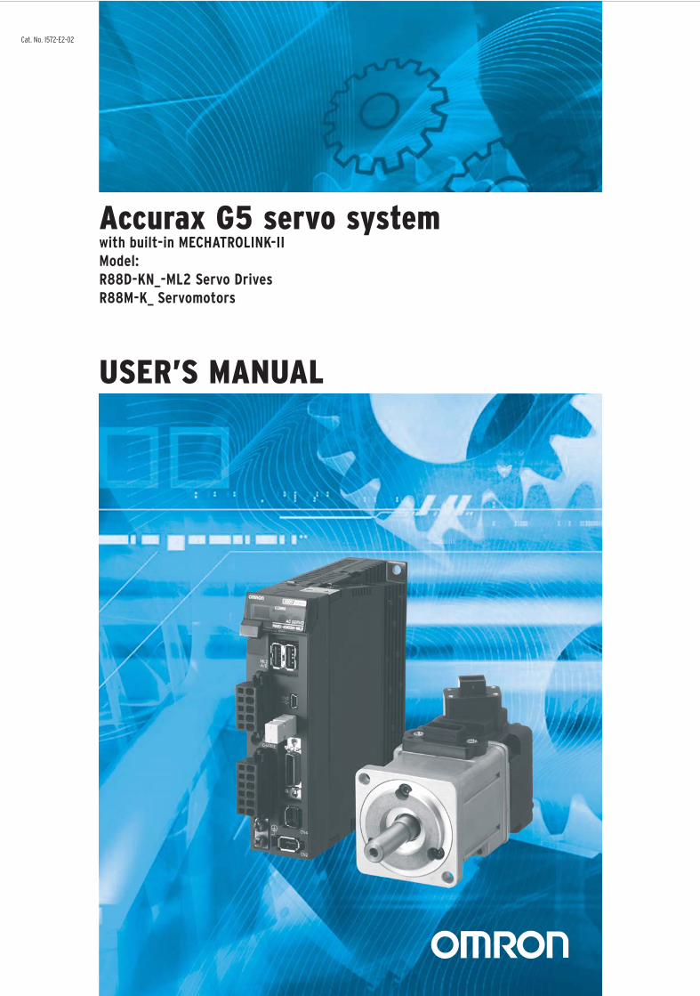
Accurax G5 servo system w
ith built-in MECHATROLINK-II
USER’S MANUAL
Cat. N
o. I5
72
-E2
-01
Accurax G5 servo system with built-in MECHATROLINK-II
Model:
R88D-KN_-ML2 Servo Drives
R88M-K_ Servomotors
USER’S MANUAL
Cat. No. I572-E2-02

1
Introduction
OMNUC G5-Series AC Servo Drives Users Manual (Built-in MECHATROLINK-II communications type)
Introduction
Thank you for purchasing the Accurax G5 Series. This user's manual explains how to install and
wire the Accurax G5 Series, set parameters needed to operate the G5 Series, and remedies to be
taken and inspection methods to be used should problems occur.
Intended Readers
This manual is intended for the following individuals.
Those having electrical knowledge (certified electricians or individuals having equivalent or more
knowledge) and also being qualified for one of the following:
Those in charge of introducing FA equipment
Those designing FA systems
Those managing FA sites
Notes
This manual contains the information you need to know to correctly use the Accurax G5 Series and
peripheral equipment.
Before using the Accurax G5 Series, read through this manual and gain a full understanding of the
information provided herein.
After you finished reading the manual, keep it in a convenient place so that the manual can be
referenced at any time.
Make sure this manual will also be delivered to the end-user.
2
Items Requiring Acknowledgment
OMNUC G5-Series AC Servo Drives Users Manual (Built-in MECHATROLINK-II communications type)
Items Requiring Acknowledgment
1. Terms of Warranty
(1) Warranty period
The warranty period of this product is 1 year after its purchase or delivery to the specified
location.
(2) Scope of warranty
If the product fails during the above warranty period due to design, material or
workmanship, we will provide a replacement unit or repair the faulty product free of
charge at the location where you purchased the product.
Take note, however, that the following failures are excluded from the scope of warranty.
a) Failure due to use or handling of the product in any condition or environment not
specified in the catalog, operation manual, etc.
b) Failure not caused by this product
c) Failure caused by any modification or repair not carried out by OMRON
d) Failure caused by any use not intended for this product
e) Failure that could not be predicted with the level of science and technology available
when the product was shipped from OMRON
f) Failure caused by a natural disaster or any other reason for which OMRON is not held
responsible
Take note that this warranty applies to the product itself, and losses induced by a failure
of the product are excluded from the scope of warranty.
2. Limited Liability
(1) OMRON shall not assume any responsibility whatsoever for any special damage, indirect
damage or passive damage arising from this product.
(2) OMRON shall not assume any responsibility for programming done by individuals not
belonging to OMRON, if the product is programmable, or outcomes of such programming.
3. Conditions for Intended Application(1) If this product is combined with other product, the customer must check the standards and
regulations applicable to such combination. The customer must also check the compatibility
of this product with any system, machinery or device used by the customer. If the above
actions are not taken, OMRON shall not assume any responsibility regarding the
compatibility of this product.
(2) If the product is used in the following applications, consult your OMRON sales representative
to check the necessary items according to the specification sheet, etc. Also make sure the
product is used within the specified ratings and performance ranges with an ample margin
and implement safety measures, such as designing a safety circuit, to minimize danger
should the product fail.
a) Used in any outdoor application, application subject to potential chemical
contamination or electrical interference, or in any condition or environment not
specified in the catalog, operation manual, etc.
b) Nuclear power control equipment, incineration equipment, railway, aircraft and vehicle
equipment, medical machinery, entertainment machinery, safety system or any other
device controlled by an administrative agency or industry regulation
c) System, machinery or device that may threaten human life or property
d) Gas, water or electricity supply system, system operated continuously for 24 hours or
any other equipment requiring high reliability
e) Any other application where a high level of safety corresponding to a) to d) above is
required
(3) If the customer wishes to use this product in any application that may threaten human life or
property, be sure to confirm beforehand that the entire system is designed in such a way to
notify dangers or ensure the necessary level of safety via design redundancy, and that the
product is wired and installed appropriately in the system according to the intended
3
Items Requiring Acknowledgment
OMNUC G5-Series AC Servo Drives Users Manual (Built-in MECHATROLINK-II communications type)
application.
(4) Sample applications explained in the catalog, etc. are provided for reference purposes only.
When adopting any of these samples, check the function and safety of each equipment or
device.
(5) Understand all prohibited items and notes on use provided herein, so that this product will be
used correctly and that customers or third parties will not suffer unexpected losses.
4. Specification ChangeThe product specifications and accessories explained in the catalog, operation manual, etc.
are subject to change, if necessary, for the reasons of improvement, etc. Contact your
OMRON sales representative to check the actual specifications of this product.
5. Scope of ServiceThe price of this product excludes costs of service such as dispatching engineers.
If you have any request regarding service, consult your OMRON sales representative.
4
Safety Precautions Document
OMNUC G5-Series AC Servo Drives Users Manual (Built-in MECHATROLINK-II communications type)
Safety Precautions Document
So that the Accurax G5-Series Servomotor and Servo Drive and peripheral equipment are used safely and correctly,
be sure to peruse this Safety Precautions document section and the main text before using the product in order to
learn all items you should know regarding the equipment as well as all safety information and precautions.
Make an arrangement so that this manual also gets to the end-user of this product.
After reading this manual, keep it with you at all times.
Explanation of Display
The precautions explained in this section describe important information regarding safety and must be followed without fail.
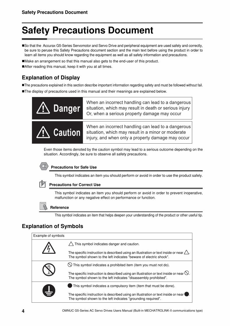
The display of precautions used in this manual and their meanings are explained below.
Even those items denoted by the caution symbol may lead to a serious outcome depending on the
situation. Accordingly, be sure to observe all safety precautions.
Precautions for Safe Use
This symbol indicates an item you should perform or avoid in order to use the product safely.
Precautions for Correct Use
This symbol indicates an item you should perform or avoid in order to prevent inoperative,
malfunction or any negative effect on performance or function.
Reference
This symbol indicates an item that helps deepen your understanding of the product or other useful tip.
Explanation of Symbols
Example of symbols
This symbol indicates danger and caution.
The specific instruction is described using an illustration or text inside or near .
The symbol shown to the left indicates "beware of electric shock".
This symbol indicates a prohibited item (item you must not do).
The specific instruction is described using an illustration or text inside or near .
The symbol shown to the left indicates "disassembly prohibited".
This symbol indicates a compulsory item (item that must be done).
The specific instruction is described using an illustration or text inside or near .
The symbol shown to the left indicates "grounding required".
Danger
CautionWhen an incorrect handling can lead to a dangerous
situation, which may result in a minor or moderate
injury, and when only a property damage may occur
When an incorrect handling can lead to a dangerous
situation, which may result in death or serious injury
Or, when a serious property damage may occur
5
Safety Precautions Document
OMNUC G5-Series AC Servo Drives Users Manual (Built-in MECHATROLINK-II communications type)
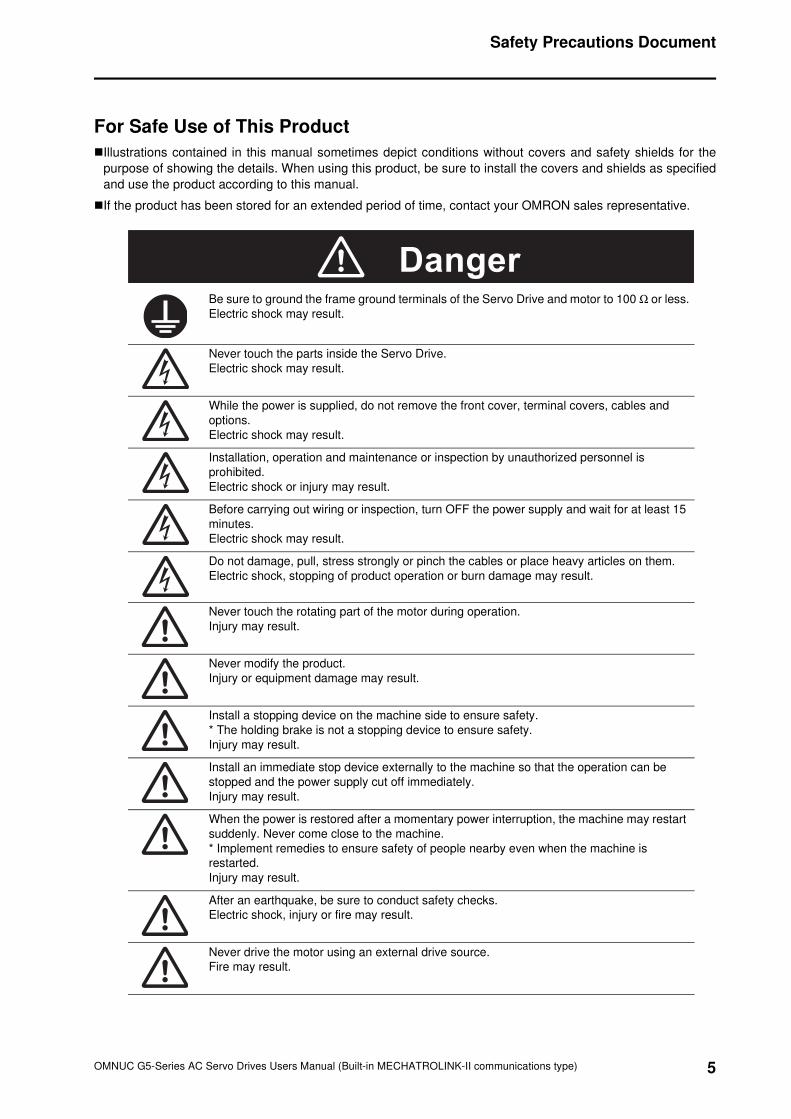
For Safe Use of This Product
Illustrations contained in this manual sometimes depict conditions without covers and safety shields for the
purpose of showing the details. When using this product, be sure to install the covers and shields as specified
and use the product according to this manual.
If the product has been stored for an extended period of time, contact your OMRON sales representative.
Be sure to ground the frame ground terminals of the Servo Drive and motor to 100 Ω or less.
Electric shock may result.
Never touch the parts inside the Servo Drive.
Electric shock may result.
While the power is supplied, do not remove the front cover, terminal covers, cables and
options.
Electric shock may result.
Installation, operation and maintenance or inspection by unauthorized personnel is
prohibited.
Electric shock or injury may result.
Before carrying out wiring or inspection, turn OFF the power supply and wait for at least 15
minutes.
Electric shock may result.
Do not damage, pull, stress strongly or pinch the cables or place heavy articles on them.
Electric shock, stopping of product operation or burn damage may result.
Never touch the rotating part of the motor during operation.
Injury may result.
Never modify the product.
Injury or equipment damage may result.
Install a stopping device on the machine side to ensure safety.
* The holding brake is not a stopping device to ensure safety.
Injury may result.
Install an immediate stop device externally to the machine so that the operation can be
stopped and the power supply cut off immediately.
Injury may result.
When the power is restored after a momentary power interruption, the machine may restart
suddenly. Never come close to the machine.
* Implement remedies to ensure safety of people nearby even when the machine is
restarted.
Injury may result.
After an earthquake, be sure to conduct safety checks.
Electric shock, injury or fire may result.
Never drive the motor using an external drive source.
Fire may result.
Danger
6
Safety Precautions Document
OMNUC G5-Series AC Servo Drives Users Manual (Built-in MECHATROLINK-II communications type)
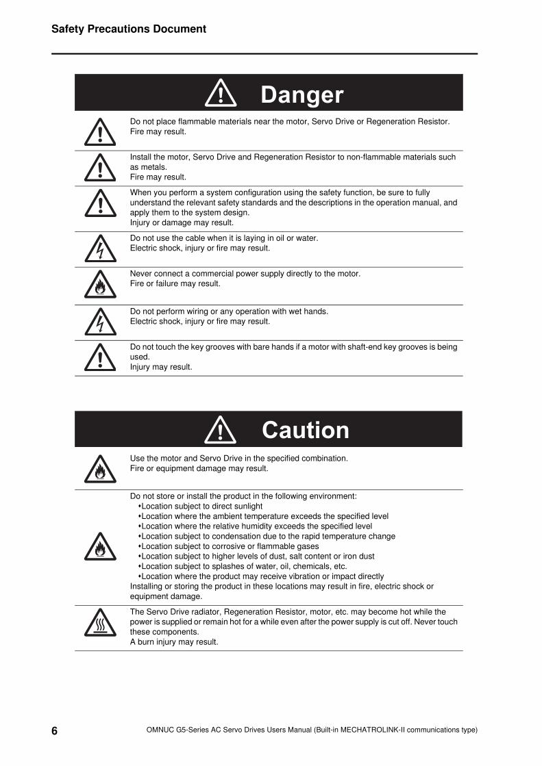
Do not place flammable materials near the motor, Servo Drive or Regeneration Resistor.
Fire may result.
Install the motor, Servo Drive and Regeneration Resistor to non-flammable materials such
as metals.
Fire may result.
When you perform a system configuration using the safety function, be sure to fully
understand the relevant safety standards and the descriptions in the operation manual, and
apply them to the system design.
Injury or damage may result.
Do not use the cable when it is laying in oil or water.
Electric shock, injury or fire may result.
Never connect a commercial power supply directly to the motor.
Fire or failure may result.
Do not perform wiring or any operation with wet hands.
Electric shock, injury or fire may result.
Do not touch the key grooves with bare hands if a motor with shaft-end key grooves is being
used.
Injury may result.
Use the motor and Servo Drive in the specified combination.
Fire or equipment damage may result.
Do not store or install the product in the following environment:
Location subject to direct sunlight
Location where the ambient temperature exceeds the specified level
Location where the relative humidity exceeds the specified level
Location subject to condensation due to the rapid temperature change
Location subject to corrosive or flammable gases
Location subject to higher levels of dust, salt content or iron dust
Location subject to splashes of water, oil, chemicals, etc.
Location where the product may receive vibration or impact directly
Installing or storing the product in these locations may result in fire, electric shock or
equipment damage.
The Servo Drive radiator, Regeneration Resistor, motor, etc. may become hot while the
power is supplied or remain hot for a while even after the power supply is cut off. Never touch
these components.
A burn injury may result.
Danger
Caution
7
Safety Precautions Document
OMNUC G5-Series AC Servo Drives Users Manual (Built-in MECHATROLINK-II communications type)
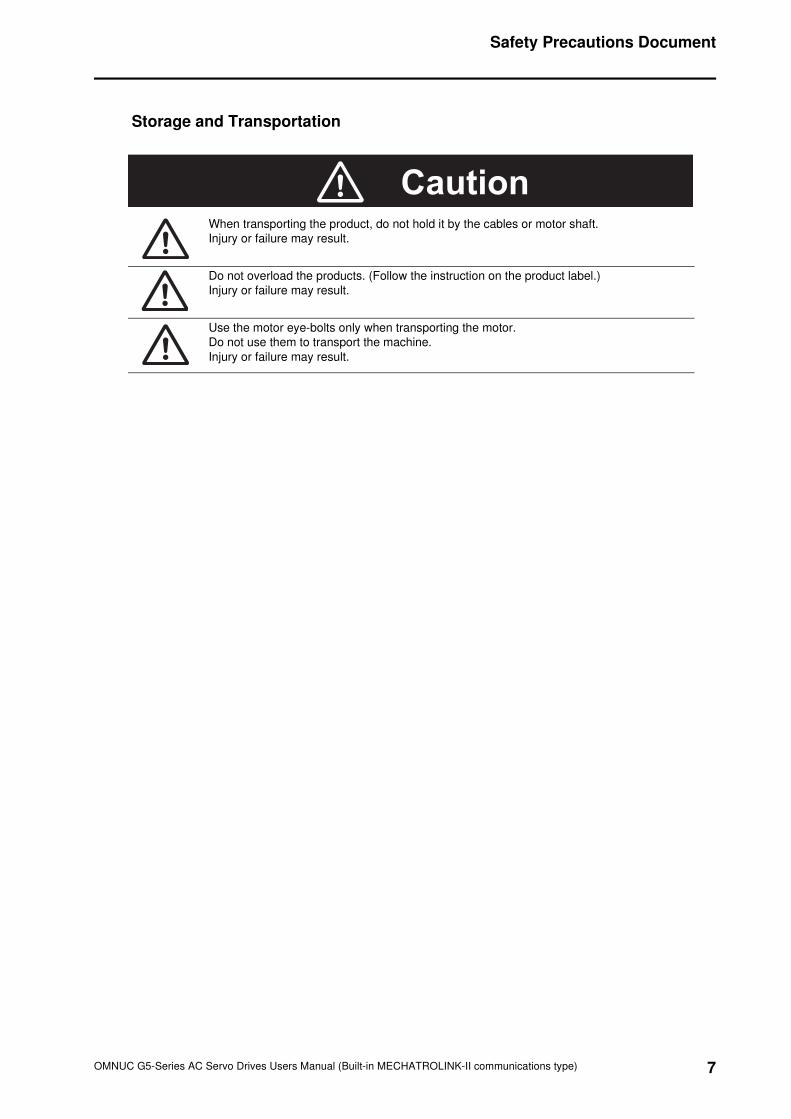
Storage and Transportation
When transporting the product, do not hold it by the cables or motor shaft.
Injury or failure may result.
Do not overload the products. (Follow the instruction on the product label.)
Injury or failure may result.
Use the motor eye-bolts only when transporting the motor.
Do not use them to transport the machine.
Injury or failure may result.
Caution
8
Safety Precautions Document
OMNUC G5-Series AC Servo Drives Users Manual (Built-in MECHATROLINK-II communications type)
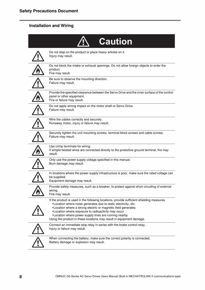
Installation and Wiring
Do not step on the product or place heavy articles on it.
Injury may result.
Do not block the intake or exhaust openings. Do not allow foreign objects to enter the
product.
Fire may result.
Be sure to observe the mounting direction.
Failure may result.
Provide the specified clearance between the Servo Drive and the inner surface of the control
panel or other equipment.
Fire or failure may result.
Do not apply strong impact on the motor shaft or Servo Drive.
Failure may result.
Wire the cables correctly and securely.
Runaway motor, injury or failure may result.
Securely tighten the unit mounting screws, terminal block screws and cable screws.
Failure may result.
Use crimp terminals for wiring.
If simple twisted wires are connected directly to the protective ground terminal, fire may
result.
Only use the power supply voltage specified in this manual.
Burn damage may result.
In locations where the power supply infrastructure is poor, make sure the rated voltage can
be supplied.
Equipment damage may result.
Provide safety measures, such as a breaker, to protect against short circuiting of external
wiring.
Fire may result.
If the product is used in the following locations, provide sufficient shielding measures.
Location where noise generates due to static electricity, etc.
Location where a strong electric or magnetic field generates
Location where exposure to radioactivity may occur
Location where power supply lines are running nearby
Using the product in these locations may result in equipment damage.
Connect an immediate stop relay in series with the brake control relay.
Injury or failure may result.
When connecting the battery, make sure the correct polarity is connected.
Battery damage or explosion may result.
Caution
9
Safety Precautions Document
OMNUC G5-Series AC Servo Drives Users Manual (Built-in MECHATROLINK-II communications type)
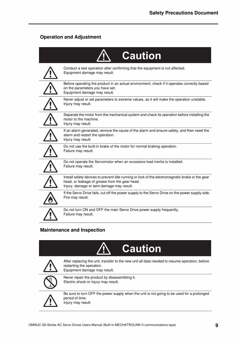
Operation and Adjustment
Maintenance and Inspection
Conduct a test operation after confirming that the equipment is not affected.
Equipment damage may result.
Before operating the product in an actual environment, check if it operates correctly based
on the parameters you have set.
Equipment damage may result.
Never adjust or set parameters to extreme values, as it will make the operation unstable.
Injury may result.
Separate the motor from the mechanical system and check its operation before installing the
motor to the machine.
Injury may result.
If an alarm generated, remove the cause of the alarm and ensure safety, and then reset the
alarm and restart the operation.
Injury may result.
Do not use the built-in brake of the motor for normal braking operation.
Failure may result.
Do not operate the Servomotor when an excessive load inertia is installed.
Failure may result.
Install safety devices to prevent idle running or lock of the electromagnetic brake or the gear
head, or leakage of grease from the gear head.
Injury, damage or taint damage may result.
If the Servo Drive fails, cut off the power supply to the Servo Drive on the power supply side.
Fire may result.
Do not turn ON and OFF the main Servo Drive power supply frequently.
Failure may result.
After replacing the unit, transfer to the new unit all data needed to resume operation, before
restarting the operation.
Equipment damage may result.
Never repair the product by disassembling it.
Electric shock or injury may result.
Be sure to turn OFF the power supply when the unit is not going to be used for a prolonged
period of time.
Injury may result.
Caution
Caution
10
Safety Precautions Document
OMNUC G5-Series AC Servo Drives Users Manual (Built-in MECHATROLINK-II communications type)
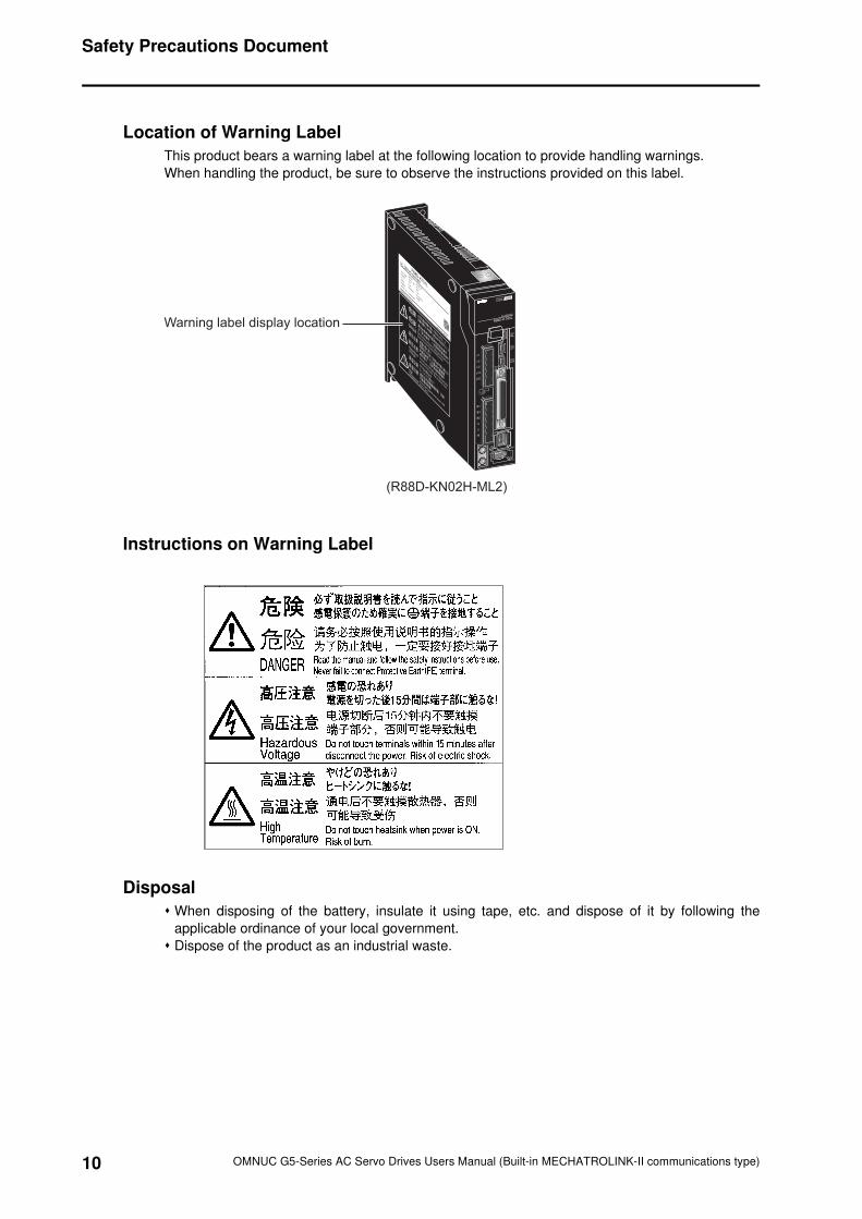
Location of Warning Label
This product bears a warning label at the following location to provide handling warnings.
When handling the product, be sure to observe the instructions provided on this label.
Instructions on Warning Label
Disposal
When disposing of the battery, insulate it using tape, etc. and dispose of it by following the
applicable ordinance of your local government.
Dispose of the product as an industrial waste.
Warning label display location
(R88D-KN02H-ML2)
11
Items to Check after Unpacking
OMNUC G5-Series AC Servo Drives Users Manual (Built-in MECHATROLINK-II communications type)
Items to Check after Unpacking
After unpacking, check the following items.
Is this the model you ordered?
Is there any damage sustained during shipment?
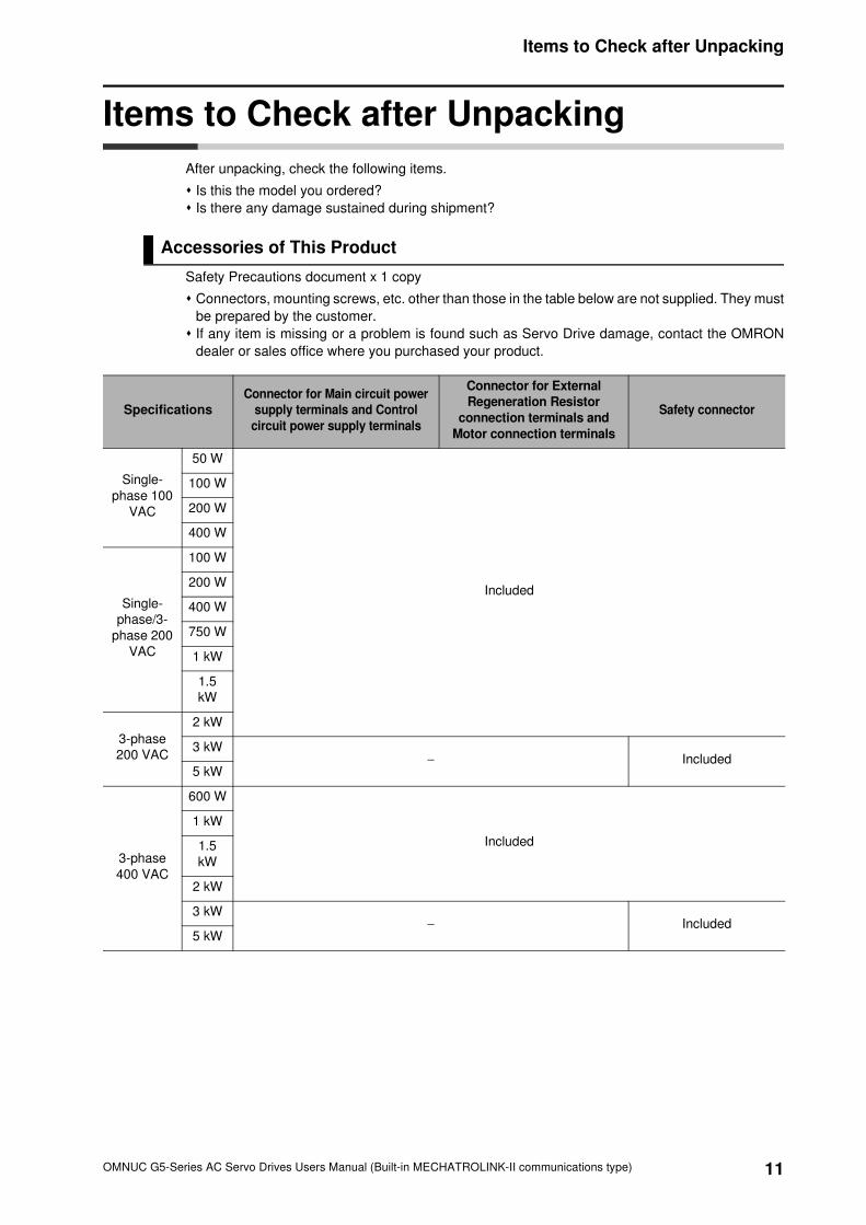
Accessories of This Product
Safety Precautions document x 1 copy
Connectors, mounting screws, etc. other than those in the table below are not supplied. They must
be prepared by the customer.
If any item is missing or a problem is found such as Servo Drive damage, contact the OMRON
dealer or sales office where you purchased your product.
Specifications
Connector for Main circuit power
supply terminals and Control
circuit power supply terminals
Connector for External
Regeneration Resistor
connection terminals and
Motor connection terminals
Safety connector
Single-
phase 100
VAC
50 W
Included
100 W
200 W
400 W
Single-
phase/3-
phase 200
VAC
100 W
200 W
400 W
750 W
1 kW
1.5
kW
3-phase
200 VAC
2 kW
3 kW− Included
5 kW
3-phase
400 VAC
600 W
Included
1 kW
1.5
kW
2 kW
3 kW− Included
5 kW
12
Manual Revision History
OMNUC G5-Series AC Servo Drives Users Manual (Built-in MECHATROLINK-II communications type)
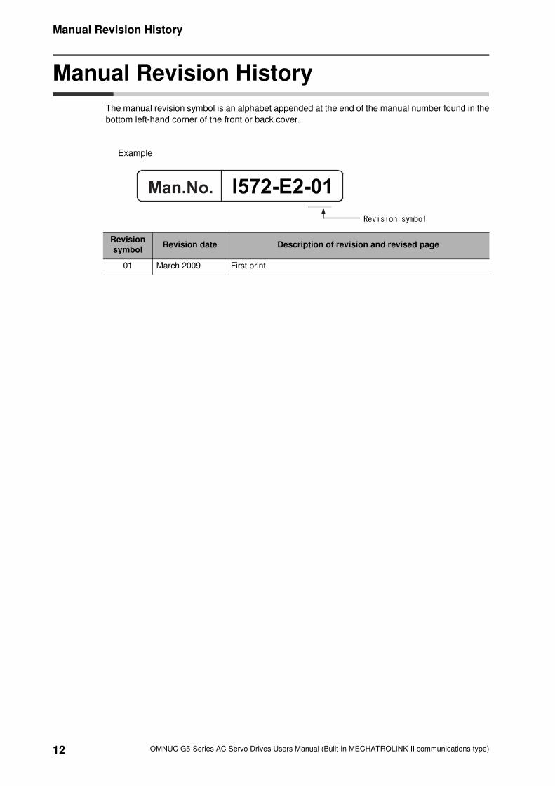
Manual Revision History
The manual revision symbol is an alphabet appended at the end of the manual number found in the
bottom left-hand corner of the front or back cover.
Example
Revision
symbolRevision date Description of revision and revised page
01 March 2009 First print
I572-E2-01
13
Structure of This Document
OMNUC G5-Series AC Servo Drives Users Manual (Built-in MECHATROLINK-II communications type)
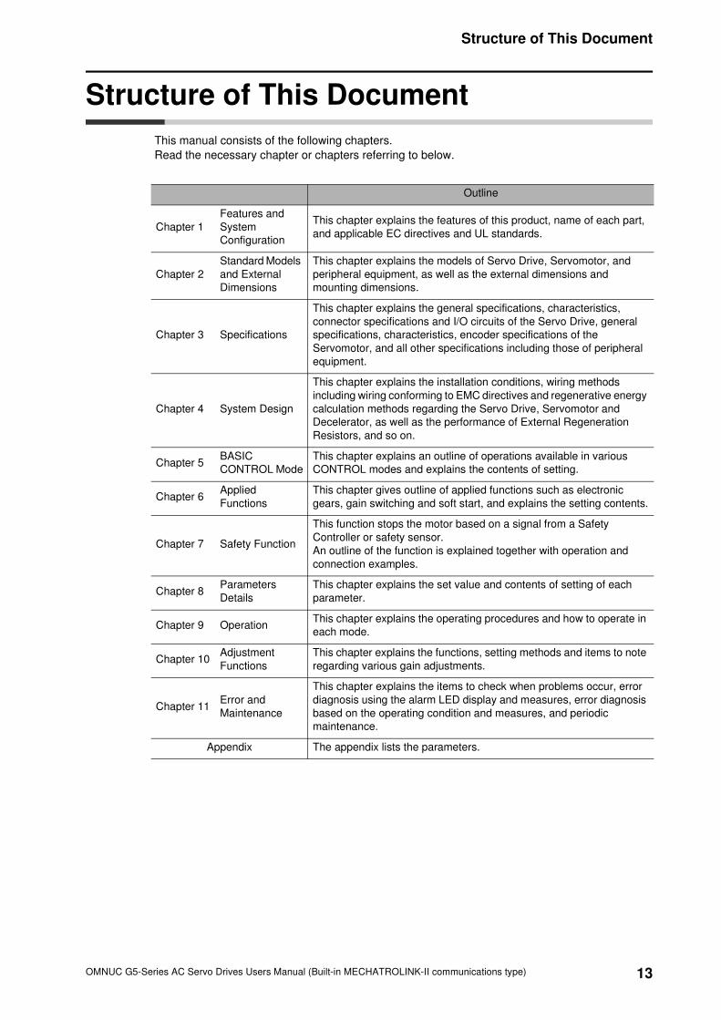
Structure of This Document
This manual consists of the following chapters.
Read the necessary chapter or chapters referring to below.
Outline
Chapter 1
Features and
System
Configuration
This chapter explains the features of this product, name of each part,
and applicable EC directives and UL standards.
Chapter 2
Standard Models
and External
Dimensions
This chapter explains the models of Servo Drive, Servomotor, and
peripheral equipment, as well as the external dimensions and
mounting dimensions.
Chapter 3 Specifications
This chapter explains the general specifications, characteristics,
connector specifications and I/O circuits of the Servo Drive, general
specifications, characteristics, encoder specifications of the
Servomotor, and all other specifications including those of peripheral
equipment.
Chapter 4 System Design
This chapter explains the installation conditions, wiring methods
including wiring conforming to EMC directives and regenerative energy
calculation methods regarding the Servo Drive, Servomotor and
Decelerator, as well as the performance of External Regeneration
Resistors, and so on.
Chapter 5BASIC
CONTROL Mode
This chapter explains an outline of operations available in various
CONTROL modes and explains the contents of setting.
Chapter 6Applied
Functions
This chapter gives outline of applied functions such as electronic
gears, gain switching and soft start, and explains the setting contents.
Chapter 7 Safety Function
This function stops the motor based on a signal from a Safety
Controller or safety sensor.
An outline of the function is explained together with operation and
connection examples.
Chapter 8Parameters
Details
This chapter explains the set value and contents of setting of each
parameter.
Chapter 9 OperationThis chapter explains the operating procedures and how to operate in
each mode.
Chapter 10Adjustment
Functions
This chapter explains the functions, setting methods and items to note
regarding various gain adjustments.
Chapter 11Error and
Maintenance
This chapter explains the items to check when problems occur, error
diagnosis using the alarm LED display and measures, error diagnosis
based on the operating condition and measures, and periodic
maintenance.
Appendix The appendix lists the parameters.
14
Table Of Contents
OMNUC G5-Series AC Servo Drives Users Manual (Built-in MECHATROLINK-II communications type)
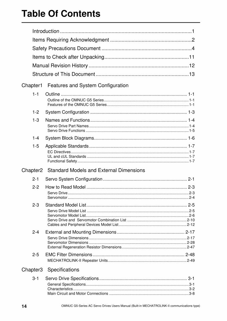
Introduction ............................................................................................1
Items Requiring Acknowledgment .........................................................2
Safety Precautions Document ...............................................................4
Items to Check after Unpacking...........................................................11
Manual Revision History ......................................................................12
Structure of This Document .................................................................13
Chapter1 Features and System Configuration
1-1 Outline ................................................................................................... 1-1
Outline of the OMNUC G5 Series................................................................................1-1
Features of the OMNUC G5 Series.............................................................................1-1
1-2 System Configuration ............................................................................ 1-3
1-3 Names and Functions............................................................................ 1-4
Servo Drive Part Names..............................................................................................1-4
Servo Drive Functions .................................................................................................1-5
1-4 System Block Diagrams......................................................................... 1-6
1-5 Applicable Standards............................................................................. 1-7
EC Directives...............................................................................................................1-7
UL and cUL Standards ................................................................................................1-7
Functional Safety.........................................................................................................1-7
Chapter2 Standard Models and External Dimensions
2-1 Servo System Configuration .................................................................. 2-1
2-2 How to Read Model ............................................................................... 2-3
Servo Drive.................................................................................................................. 2-3
Servomotor .................................................................................................................. 2-4
2-3 Standard Model List............................................................................... 2-5
Servo Drive Model List ................................................................................................2-5
Servomotor Model List.................................................................................................2-6
Servo Drive and Servomotor Combination List ........................................................2-10
Cables and Peripheral Devices Model List ................................................................2-12
2-4 External and Mounting Dimensions ..................................................... 2-17
Servo Drive Dimensions ............................................................................................2-17
Servomotor Dimensions ............................................................................................2-28
External Regeneration Resistor Dimensions............................................................. 2-47
2-5 EMC Filter Dimensions ........................................................................ 2-48
MECHATROLINK-II Repeater Units.......................................................................... 2-49
Chapter3 Specifications
3-1 Servo Drive Specifications..................................................................... 3-1
General Specifications.................................................................................................3-1
Characteristics.............................................................................................................3-2
Main Circuit and Motor Connections ...........................................................................3-8
15
Table Of Contents
OMNUC G5-Series AC Servo Drives Users Manual (Built-in MECHATROLINK-II communications type)
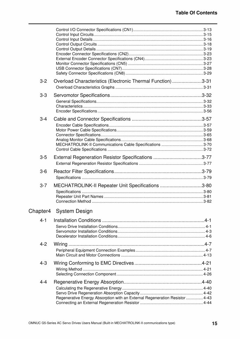
Control I/O Connector Specifications (CN1).............................................................. 3-13
Control Input Circuits ................................................................................................. 3-15
Control Input Details .................................................................................................. 3-16
Control Output Circuits .............................................................................................. 3-18
Control Output Details ............................................................................................... 3-19
Encoder Connector Specifications (CN2).................................................................. 3-23
External Encoder Connector Specifications (CN4).................................................... 3-23
Monitor Connector Specifications (CN5) ................................................................... 3-27
USB Connector Specifications (CN7)........................................................................ 3-28
Safety Connector Specifications (CN8) ..................................................................... 3-29
3-2 Overload Characteristics (Electronic Thermal Function) ......................3-31
Overload Characteristics Graphs .............................................................................. 3-31
3-3 Servomotor Specifications....................................................................3-32
General Specifications............................................................................................... 3-32
Characteristics........................................................................................................... 3-33
Encoder Specifications.............................................................................................. 3-56
3-4 Cable and Connector Specifications ....................................................3-57
Encoder Cable Specifications.................................................................................... 3-57
Motor Power Cable Specifications............................................................................. 3-59
Connector Specifications........................................................................................... 3-65
Analog Monitor Cable Specifications......................................................................... 3-68
MECHATROLINK-II Communications Cable Specifications ..................................... 3-70
Control Cable Specifications ..................................................................................... 3-72
3-5 External Regeneration Resistor Specifications ....................................3-77
External Regeneration Resistor Specifications ......................................................... 3-77
3-6 Reactor Filter Specifications.................................................................3-79
Specifications ............................................................................................................ 3-79
3-7 MECHATROLINK-II Repeater Unit Specifications ...............................3-80
Specifications ............................................................................................................ 3-80
Repeater Unit Part Names ........................................................................................ 3-81
Connection Method ................................................................................................... 3-82
Chapter4 System Design
4-1 Installation Conditions ............................................................................4-1
Servo Drive Installation Conditions.............................................................................. 4-1
Servomotor Installation Conditions.............................................................................. 4-3
Decelerator Installation Conditions.............................................................................. 4-6
4-2 Wiring .....................................................................................................4-7
Peripheral Equipment Connection Examples.............................................................. 4-7
Main Circuit and Motor Connections ......................................................................... 4-13
4-3 Wiring Conforming to EMC Directives ..................................................4-21
Wiring Method ........................................................................................................... 4-21
Selecting Connection Component ............................................................................. 4-26
4-4 Regenerative Energy Absorption..........................................................4-40
Calculating the Regenerative Energy........................................................................ 4-40
Servo Drive Regeneration Absorption Capacity ........................................................ 4-42
Regenerative Energy Absorption with an External Regeneration Resistor ............... 4-43
Connecting an External Regeneration Resistor ........................................................ 4-44

16
Table Of Contents
OMNUC G5-Series AC Servo Drives Users Manual (Built-in MECHATROLINK-II communications type)
Chapter5 BASIC CONTROL Mode
5-1 Position Control ..................................................................................... 5-1
Parameters Requiring Settings....................................................................................5-1
Related Functions........................................................................................................5-2
Parameter Block Diagram for POSITION CONTROL mode .......................................5-3
5-2 Speed Control........................................................................................ 5-4
Parameters Requiring Settings....................................................................................5-4
Related Functions........................................................................................................5-4
Parameter Block Diagram for SPEED CONTROL mode ............................................ 5-5
5-3 Torque Control....................................................................................... 5-6
Parameters Requiring Settings....................................................................................5-6
Related Functions........................................................................................................5-7
Parameter Block Diagram for TORQUE CONTROL mode .........................................5-8
5-4 Full Closing Control ............................................................................... 5-9
Outline of Operation ....................................................................................................5-9
Parameters Requiring Settings..................................................................................5-10
Parameter Block Diagram for FULL CLOSING CONTROL mode............................. 5-16
Chapter6 Applied Functions
6-1 Sequence I/O Signal.............................................................................. 6-1
Input Signals................................................................................................................6-1
Output Signals .............................................................................................................6-4
6-2 Forward and Reverse Drive Prohibition Functions ................................ 6-6
Parameters Requiring Settings....................................................................................6-6
6-3 Overrun Protection................................................................................. 6-9
Operating Conditions...................................................................................................6-9
Parameters Requiring Settings....................................................................................6-9
Operation Example.................................................................................................... 6-10
6-4 Backlash Compensation ...................................................................... 6-11
Parameters Requiring Settings..................................................................................6-11
6-5 Brake Interlock..................................................................................... 6-13
Parameters Requiring Settings..................................................................................6-13
Operating Example.................................................................................................... 6-14
6-6 Electronic Gear Function ..................................................................... 6-18
Parameters Requiring Settings..................................................................................6-18
Operation Example.................................................................................................... 6-20
6-7 Torque Limit Switching ........................................................................ 6-21
Operating Conditions.................................................................................................6-21
Parameters Requiring Settings..................................................................................6-21
6-8 Soft Start.............................................................................................. 6-23
Parameters Requiring Settings..................................................................................6-23
Soft Start Acceleration or Deceleration Time ............................................................6-23
S-curve Acceleration or Deceleration Time ...............................................................6-24
6-9 Gain Switching Function ...................................................................... 6-25
Parameters Requiring Settings..................................................................................6-26
Gain Switching Setting for Each CONTROL mode ...................................................6-27
Timing by Gain Switching Setting..............................................................................6-32
17
Table Of Contents
OMNUC G5-Series AC Servo Drives Users Manual (Built-in MECHATROLINK-II communications type)
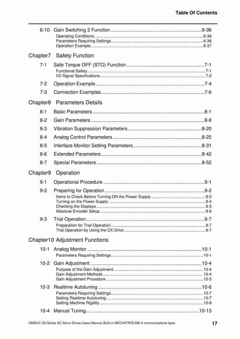
6-10 Gain Switching 3 Function....................................................................6-36
Operating Conditions................................................................................................. 6-36
Parameters Requiring Settings.................................................................................. 6-36
Operation Example.................................................................................................... 6-37
Chapter7 Safety Function
7-1 Safe Torque OFF (STO) Function ..........................................................7-1
Functional Safety......................................................................................................... 7-1
I/O Signal Specifications.............................................................................................. 7-2
7-2 Operation Example.................................................................................7-4
7-3 Connection Examples.............................................................................7-6
Chapter8 Parameters Details
8-1 Basic Parameters ...................................................................................8-1
8-2 Gain Parameters ....................................................................................8-8
8-3 Vibration Suppression Parameters.......................................................8-20
8-4 Analog Control Parameters ..................................................................8-25
8-5 Interface Monitor Setting Parameters...................................................8-31
8-6 Extended Parameters...........................................................................8-42
8-7 Special Parameters ..............................................................................8-52
Chapter9 Operation
9-1 Operational Procedure ...........................................................................9-1
9-2 Preparing for Operation ..........................................................................9-2
Items to Check Before Turning ON the Power Supply ................................................ 9-2
Turning on the Power Supply ...................................................................................... 9-4
Checking the Displays................................................................................................. 9-5
Absolute Encoder Setup.............................................................................................. 9-6
9-3 Trial Operation........................................................................................9-7
Preparation for Trial Operation .................................................................................... 9-7
Trial Operation by Using the CX-Drive ........................................................................ 9-7
Chapter10 Adjustment Functions
10-1 Analog Monitor .....................................................................................10-1
Parameters Requiring Settings.................................................................................. 10-1
10-2 Gain Adjustment ...................................................................................10-4
Purpose of the Gain Adjustment................................................................................ 10-4
Gain Adjustment Methods ......................................................................................... 10-4
Gain Adjustment Procedure ...................................................................................... 10-5
10-3 Realtime Autotuning .............................................................................10-6
Parameters Requiring Settings.................................................................................. 10-7
Setting Realtime Autotuning ...................................................................................... 10-7
Setting Machine Rigidity ............................................................................................ 10-8
10-4 Manual Tuning....................................................................................10-13
18
Table Of Contents
OMNUC G5-Series AC Servo Drives Users Manual (Built-in MECHATROLINK-II communications type)
Basic Settings..........................................................................................................10-13
10-5 Damping Control................................................................................ 10-21
Outline of Operation ................................................................................................10-21
Parameters Requiring Settings................................................................................10-22
10-6 Adaptive Filter.................................................................................... 10-25
Parameters Requiring Settings................................................................................10-26
Operating Procedure ...............................................................................................10-27
10-7 Notch Filter ........................................................................................ 10-28
Parameters Requiring Settings................................................................................10-29
10-8 Disturbance Observer Function ......................................................... 10-31
Operating Conditions...............................................................................................10-31
Parameters Requiring Settings................................................................................10-32
Operating Procedure ...............................................................................................10-32
10-9 Friction Torque Compensation Function............................................ 10-33
Operating Conditions...............................................................................................10-33
Parameters Requiring Settings................................................................................10-33
Operation Example.................................................................................................. 10-34
10-10 Hybrid Vibration Suppression Function ............................................ 10-35
Operating Conditions...............................................................................................10-35
Parameters Requiring Settings................................................................................10-35
Operating Procedure ...............................................................................................10-35
10-11 Feed-forward Function...................................................................... 10-36
Parameters Requiring Settings................................................................................10-36
Operating Procedure ...............................................................................................10-37
10-12 Instantaneous Speed Observer Function ......................................... 10-39
Operating Conditions...............................................................................................10-39
Parameters Requiring Settings................................................................................10-39
Operating Procedure ...............................................................................................10-40
Chapter11 Error and Maintenance
11-1 Error Processing .................................................................................. 11-1
Preliminary Checks When a Problem Occurs ...........................................................11-1
Precautions When a Problem Occurs .......................................................................11-2
Replacing the Servomotor and Servo Drive ..............................................................11-3
11-2 Warning ............................................................................................... 11-4
Warning List...............................................................................................................11-4
11-3 Alarms.................................................................................................. 11-6
Emergency Stop Operation at Alarms .....................................................................11-13
11-4 Troubleshooting ................................................................................. 11-15
Error Diagnosis Using the Alarm Displays...............................................................11-15
Error Diagnosis Using the Operation Status............................................................11-27
11-5 Periodic Maintenance ........................................................................ 11-35
Servomotor Life Expectancy....................................................................................11-35
Servo Drive Life Expectancy ...................................................................................11-36
Replacing the Absolute Encoder Battery ................................................................11-37
19
Table Of Contents
OMNUC G5-Series AC Servo Drives Users Manual (Built-in MECHATROLINK-II communications type)
Appendix
A-1 Parameter List ....................................................................................... A-1
Index

OMNUC G5-Series AC Servo Drives Users Manual (Built-in MECHATROLINK-II communications type)
1
1This chapter explains the features of this product, name of each part, and
applicable EC directives and UL standards.
1-1 Outline ...........................................................................1-1
1-2 System Configuration ..................................................1-3
1-3 Names and Functions ..................................................1-4
1-4 System Block Diagrams...............................................1-6
1-5 Applicable Standards.................................................1-11
Features and System Configuration
1-1
1-1 Outline
1
OMNUC G5-Series AC Servo Drives Users Manual (Built-in MECHATROLINK-II communications type)
Fea
ture
s a
nd
Sy
ste
m C
on
fig
ura
tio
n
1-1 Outline
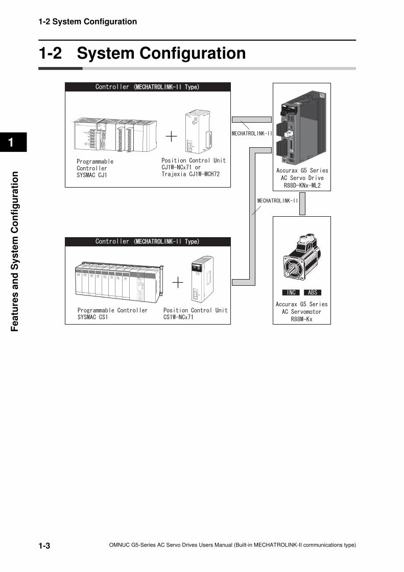
Outline of the Accurax G5 Series
The Accurax G5-Series AC Servo Drives (Built-in MECHATROLINK-II communications
support type) are a series of Servo Drives supporting the MECHATROLINK-II high-speed
motion field network.
When you use it with the MECHATROLINK-II Position Control Unit (CJ1W-NCF71, CS1W-
NCF71, CJ1W-MCH72 or other), you can create a sophisticated positioning control system.
Also, you need only one communications cable to connect the Servo Drive and the Controller.
Therefore, you can realize a position control system easily with reduced wiring effort.
With real time autotuning, adaptive filter, notch filter, and damping control, you can set up a
system that provides stable operation by suppressing vibration in low-rigidity machines.
Features of the Accurax G5 Series
The Accurax G5 Series has the following features.
Data Transmission Using MECHATROLINK-II Communications
When you use it with the MECHATROLINK-II Position Control Unit (CJ1W-NCF71, CS1W-
NCF71, CJ1W-MCH72 or other), you can exchange all control data between the Servo Drive
and the Controller through data communications.
Since the various control commands are transmitted via data communications, Servomotor's
operational performance is maximized without being limited by interface specifications such as
the response frequency of the encoder feedback pulses.
Therefore, you can use the Servo Drive's various control parameters and monitor data on a
host controller, and unify the system data for management.
Achievement of Accurate Positioning by Full Closing Control
Feedbacks from the external encoder connected to the motor are used to accurately control
positions. Accordingly, position control is not affected by deviation caused by ball screws or
temperature.
Wide Range of Power Supplies to Match Any Necessity
The Accurax G5 Series now has models supporting 400 V for use with large equipment, at
overseas facilities and in wide-ranging applications and environment. Since the utilization ratio
of facility equipment also increases, the TCO (Total Cost of Ownership) will come down.
Safe Torque OFF (STO) Function to Ensure Safety
You can cut off the motor current to stop the motor based on a signal from an emergency stop
button or other safety equipment. In addition to the conventional stop method based on a
control signal, the STO function that permits direct stopping without a need to involve the
control circuit provides the emergency stop from 2 systems, thereby enhancing safety.
Suppressing Vibration of Low-rigidity Mechanisms during Acceleration/Deceleration
The damping control function suppresses vibration of low-rigidity mechanisms or devices
whose tips tend to vibrate.
1-2
1-1 Outline
1
OMNUC G5-Series AC Servo Drives Users Manual (Built-in MECHATROLINK-II communications type)
Fe
atu
res
an
d S
ys
tem
Co
nfig
ura
tion
Two damping filters are provided to enable switching the damping frequency automatically
according to the rotation direction and also via an external signal. In addition, the settings can
be made easily merely by just setting the damping frequency and filter values, and you are
assured of stable operation even if the set values are inappropriate.
1-3
1-2 System Configuration
1
OMNUC G5-Series AC Servo Drives Users Manual (Built-in MECHATROLINK-II communications type)
Fea
ture
s a
nd
Sy
ste
m C
on
fig
ura
tio
n
1-2 System Configuration
1-4
1-3 Names and Functions
1
OMNUC G5-Series AC Servo Drives Users Manual (Built-in MECHATROLINK-II communications type)
Fe
atu
res
an
d S
ys
tem
Co
nfig
ura
tion
1-3 Names and Functions
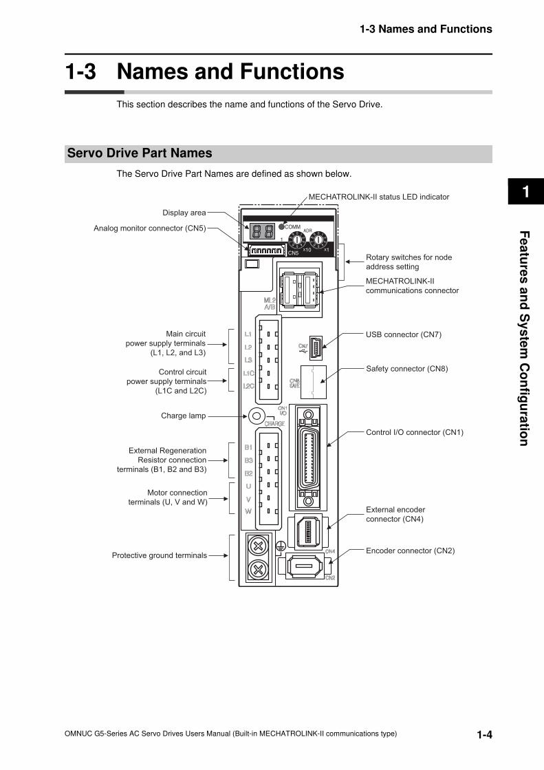
This section describes the name and functions of the Servo Drive.
Servo Drive Part Names
The Servo Drive Part Names are defined as shown below.
Display area
Rotary switches for node
address setting
MECHATROLINK-II status LED indicator
MECHATROLINK-II
communications connector
USB connector (CN7)
Analog monitor connector (CN5)
Motor connection
terminals (U, V and W)
Control circuit
power supply terminals
(L1C and L2C)
Main circuit
power supply terminals
(L1, L2, and L3)
External Regeneration
Resistor connection
terminals (B1, B2 and B3)
Protective ground terminals
Control I/O connector (CN1)
Safety connector (CN8)
External encoder
connector (CN4)
Encoder connector (CN2)
Charge lamp
1-5
1-3 Names and Functions
1
OMNUC G5-Series AC Servo Drives Users Manual (Built-in MECHATROLINK-II communications type)
Fea
ture
s a
nd
Sy
ste
m C
on
fig
ura
tio
n
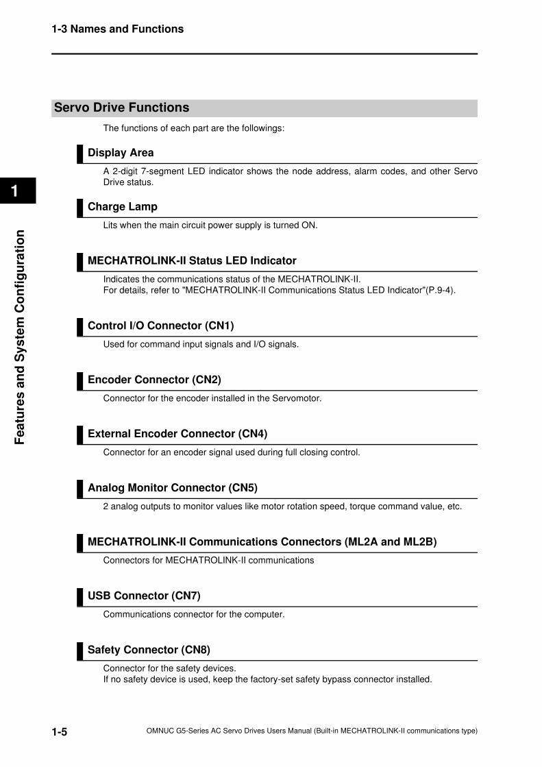
Servo Drive Functions
The functions of each part are the followings:
Display Area
A 2-digit 7-segment LED indicator shows the node address, alarm codes, and other Servo
Drive status.
Charge Lamp
Lits when the main circuit power supply is turned ON.
MECHATROLINK-II Status LED Indicator
Indicates the communications status of the MECHATROLINK-II.
For details, refer to "MECHATROLINK-II Communications Status LED Indicator"(P.9-4).
Control I/O Connector (CN1)
Used for command input signals and I/O signals.
Encoder Connector (CN2)
Connector for the encoder installed in the Servomotor.
External Encoder Connector (CN4)
Connector for an encoder signal used during full closing control.
Analog Monitor Connector (CN5)
2 analog outputs to monitor values like motor rotation speed, torque command value, etc.
MECHATROLINK-II Communications Connectors (ML2A and ML2B)
Connectors for MECHATROLINK-II communications
USB Connector (CN7)
Communications connector for the computer.
Safety Connector (CN8)
Connector for the safety devices.
If no safety device is used, keep the factory-set safety bypass connector installed.
1-6
1-4 System Block Diagrams
1
OMNUC G5-Series AC Servo Drives Users Manual (Built-in MECHATROLINK-II communications type)
Fe
atu
res
an
d S
ys
tem
Co
nfig
ura
tion
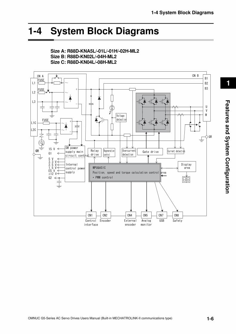
1-4 System Block Diagrams
Size A: R88D-KNA5L/-01L/-01H/-02H-ML2Size B: R88D-KN02L/-04H-ML2Size C: R88D-KN04L/-08H-ML2
+
−
+
−
±
•
1-7
1-4 System Block Diagrams
1
OMNUC G5-Series AC Servo Drives Users Manual (Built-in MECHATROLINK-II communications type)
Fea
ture
s a
nd
Sy
ste
m C
on
fig
ura
tio
n
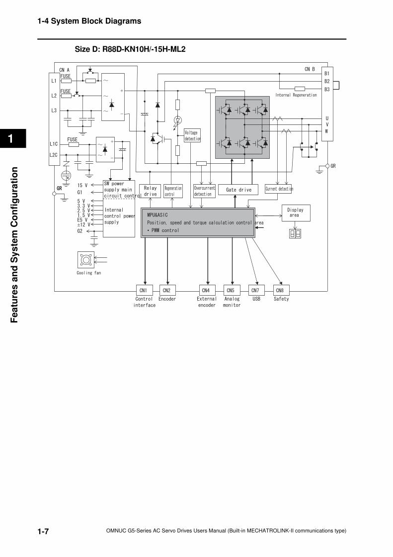
Size D: R88D-KN10H/-15H-ML2
+
−
+
−
±
•
1-8
1-4 System Block Diagrams
1
OMNUC G5-Series AC Servo Drives Users Manual (Built-in MECHATROLINK-II communications type)
Fe
atu
res
an
d S
ys
tem
Co
nfig
ura
tion
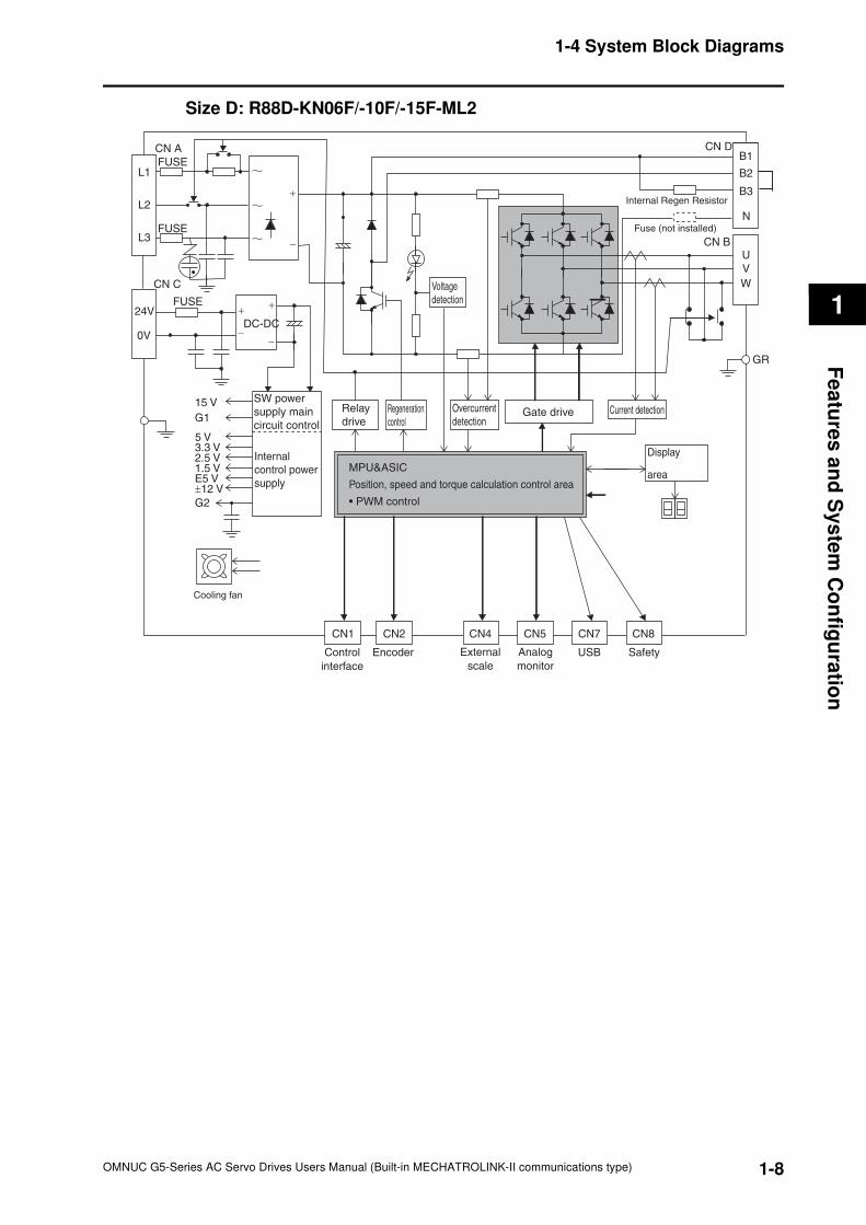
Size D: R88D-KN06F/-10F/-15F-ML2
Display
area
Gate drive
SW power
supply main
circuit control
Internal
control power
supply
0V
24V
L3
L2
L1
FUSE
FUSE
FUSE
CN A
+
−
+
−
15 V
G1
5 V
2.5 V1.5 V
±12 VE5 V
G2
3.3 V
Overcurrent
detectionCurrent detection
Voltage
detection
Regeneration
control
Relay
drive
GR
Control
interface
CN2 CN4 CN5 CN7
B1
B2
B3
CN D
U
V
W
MPU&ASIC
Position, speed and torque calculation control area
• PWM control
CN8
Encoder External
scale
Analog
monitor
USB Safety
CN1
Internal Regen Resistor
Cooling fan
N
CN B
Fuse (not installed)
+
−
DC-DC
CN C
1-9
1-4 System Block Diagrams
1
OMNUC G5-Series AC Servo Drives Users Manual (Built-in MECHATROLINK-II communications type)
Fea
ture
s a
nd
Sy
ste
m C
on
fig
ura
tio
n
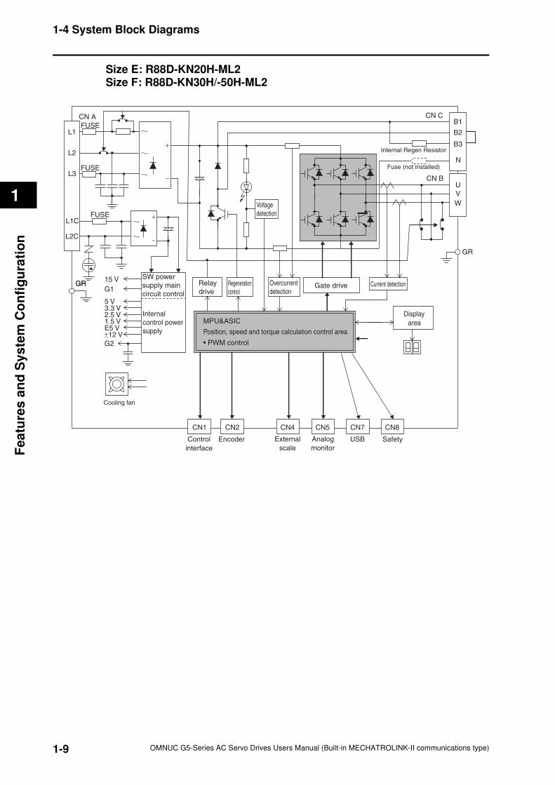
Size E: R88D-KN20H-ML2Size F: R88D-KN30H/-50H-ML2
GR
Display
area
Gate drive
SW power
supply main
circuit control
Internal
control power
supply
GR
L2C
L1C
L3
L2
L1
FUSE
FUSE
FUSE
CN A
+
−
+
−
15 V
G1
5 V
2.5 V1.5 V
±12 VE5 V
G2
3.3 V
Overcurrent
detectionCurrent detection
Voltage
detection
Regeneration
control
Relay
drive
GR
Control
interface
CN2 CN4 CN5 CN7
B1
B2
B3
CN C
U
V
W
MPU&ASIC
Position, speed and torque calculation control area
• PWM control
CN8
Encoder External
scale
Analog
monitor
USB Safety
CN1
Internal Regen Resistor
Cooling fan
N
CN B
Fuse (not installed)
1-10
1-4 System Block Diagrams
1
OMNUC G5-Series AC Servo Drives Users Manual (Built-in MECHATROLINK-II communications type)
Fe
atu
res
an
d S
ys
tem
Co
nfig
ura
tion
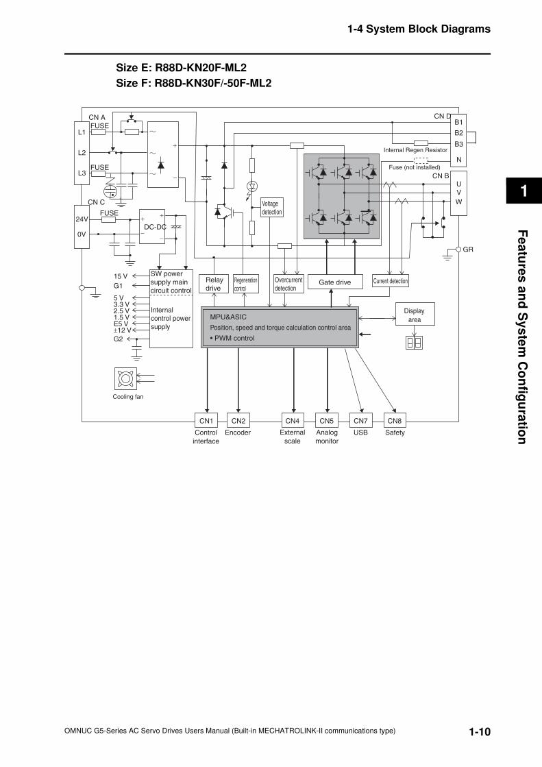
Size E: R88D-KN20F-ML2
Size F: R88D-KN30F/-50F-ML2
Display
area
Gate drive
SW power
supply main
circuit control
Internal
control power
supply
0V
24V
L3
L2
L1
FUSE
FUSE
FUSE
CN A
+
−
+
−
15 V
G1
5 V
2.5 V1.5 V
±12 VE5 V
G2
3.3 V
Overcurrent
detectionCurrent detection
Voltage
detection
Regeneration
control
Relay
drive
GR
Control
interface
CN2 CN4 CN5 CN7
B1
B2
B3
CN D
U
V
W
MPU&ASIC
Position, speed and torque calculation control area
• PWM control
CN8
Encoder External
scale
Analog
monitor
USB Safety
CN1
Internal Regen Resistor
Cooling fan
N
CN B
Fuse (not installed)
+
−
DC-DC
CN C
1-11
1-5 Applicable Standards
1
OMNUC G5-Series AC Servo Drives Users Manual (Built-in MECHATROLINK-II communications type)
Fe
atu
res
an
d S
ys
tem
Co
nfig
ura
tion
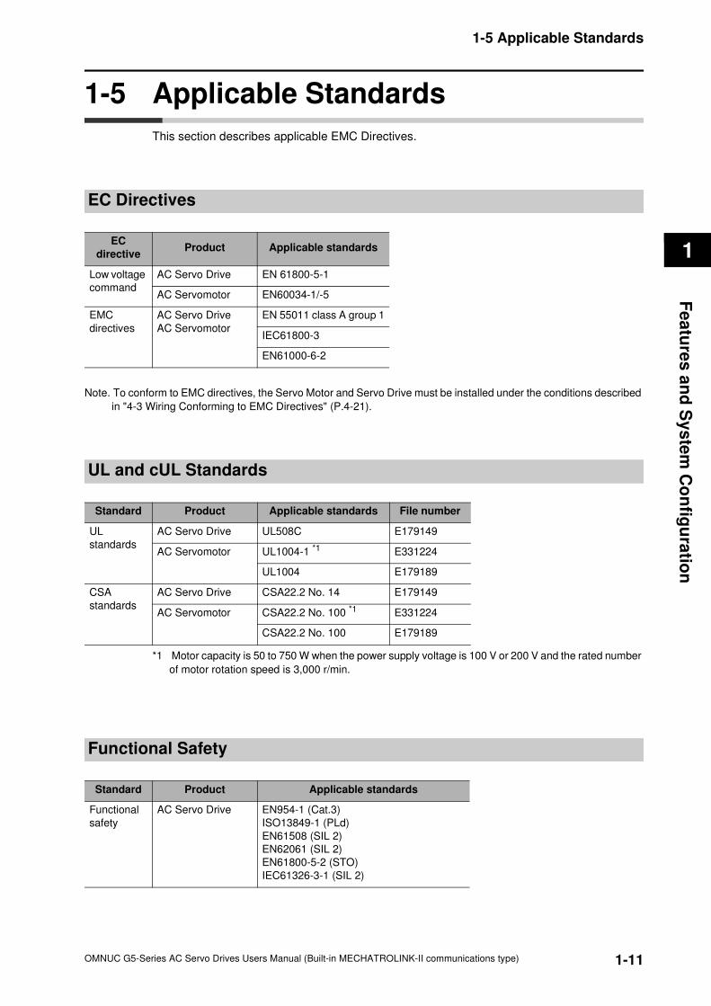
1-5 Applicable Standards
This section describes applicable EMC Directives.
EC Directives
Note. To conform to EMC directives, the Servo Motor and Servo Drive must be installed under the conditions described
in "4-3 Wiring Conforming to EMC Directives" (P.4-21).
UL and cUL Standards
*1 Motor capacity is 50 to 750 W when the power supply voltage is 100 V or 200 V and the rated number
of motor rotation speed is 3,000 r/min.
Functional Safety
EC
directiveProduct Applicable standards
Low voltage
command
AC Servo Drive EN 61800-5-1
AC Servomotor EN60034-1/-5
EMC
directives
AC Servo Drive
AC Servomotor
EN 55011 class A group 1
IEC61800-3
EN61000-6-2
Standard Product Applicable standards File number
UL
standards
AC Servo Drive UL508C E179149
AC Servomotor UL1004-1 *1 E331224
UL1004 E179189
CSA
standards
AC Servo Drive CSA22.2 No. 14 E179149
AC Servomotor CSA22.2 No. 100 *1 E331224
CSA22.2 No. 100 E179189
Standard Product Applicable standards
Functional
safety
AC Servo Drive EN954-1 (Cat.3)
ISO13849-1 (PLd)
EN61508 (SIL 2)
EN62061 (SIL 2)
EN61800-5-2 (STO)
IEC61326-3-1 (SIL 2)
OMNUC G5-Series AC Servo Drives Users Manual (Built-in MECHATROLINK-II communications type)
2
2Accurax
This chapter explains the models of Servo Drive, Servomotor, and peripheral
equipment, as well as the external dimensions and mounting dimensions.
2-1 Servo System Configuration .......................................2-1
2-2 How to Read Model.......................................................2-3
2-3 Standard Model List .....................................................2-5
2-4 External and Mounting Dimensions..........................2-21
2-5 EMC Filter Dimensions...............................................2-52
Standard Models and External Dimensions
2-1
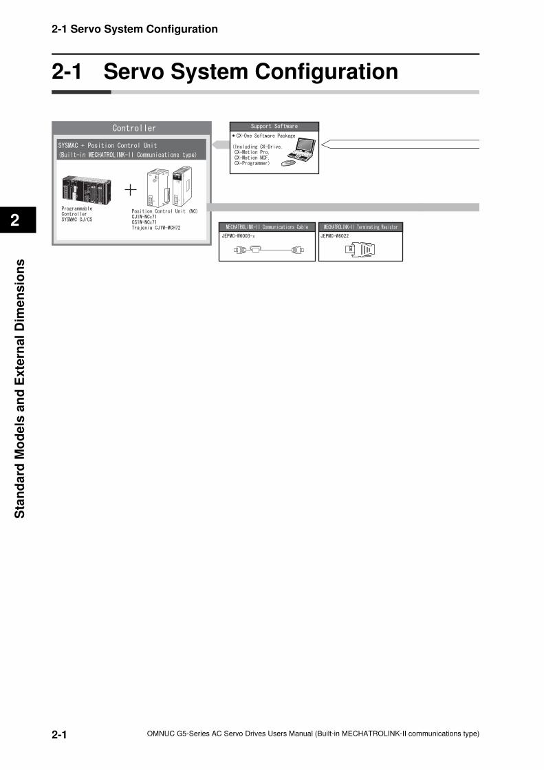
2-1 Servo System Configuration
OMNUC G5-Series AC Servo Drives Users Manual (Built-in MECHATROLINK-II communications type)
2
Sta
nd
ard
Mo
de
ls a
nd
Exte
rnal
Dim
en
sio
ns
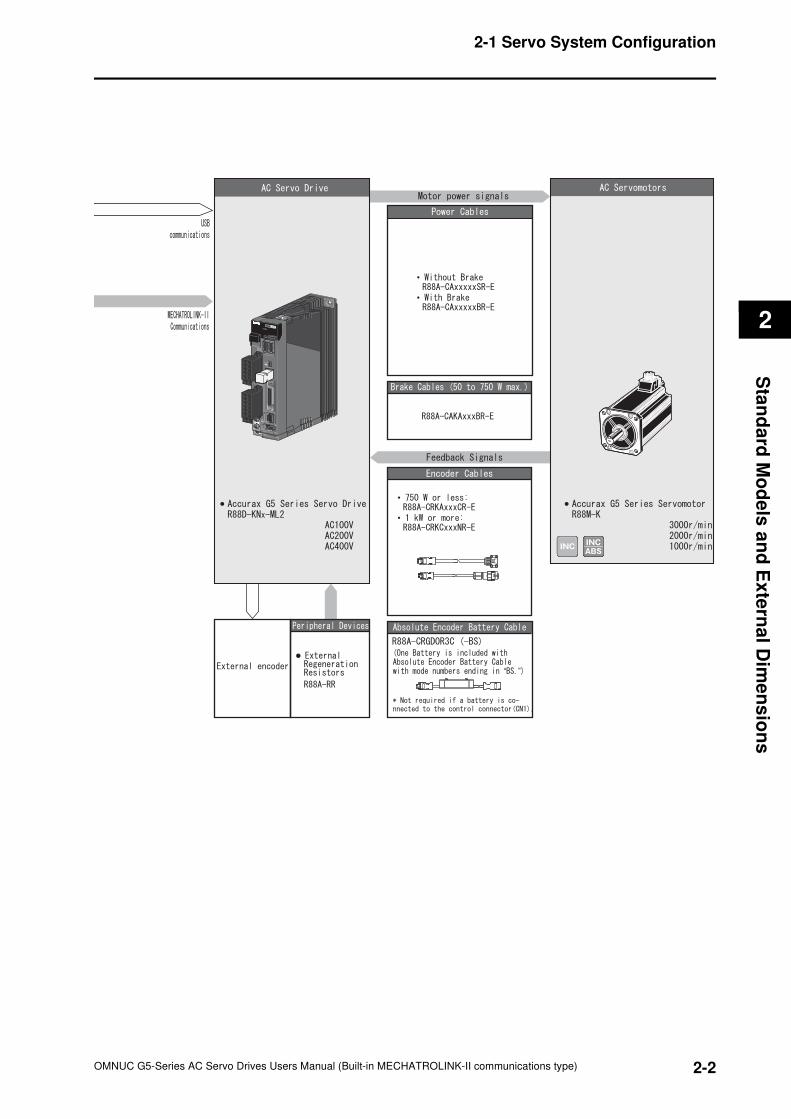
2-1 Servo System Configuration
2-2
2-1 Servo System Configuration
OMNUC G5-Series AC Servo Drives Users Manual (Built-in MECHATROLINK-II communications type)
2
Sta
nd
ard
Mo
de
ls a
nd
Ex
tern
al D
ime
ns
ion
s
•
•
•
•
“ ”
ML2A/B
ML2A/B
2-3
2-2 How to Read Model
OMNUC G5-Series AC Servo Drives Users Manual (Built-in MECHATROLINK-II communications type)
2
Sta
nd
ard
Mo
de
ls a
nd
Exte
rnal
Dim
en
sio
ns
2-2 How to Read Model
This section describes how to read and understand the model numbers for Servo Drives and
Servomotors.
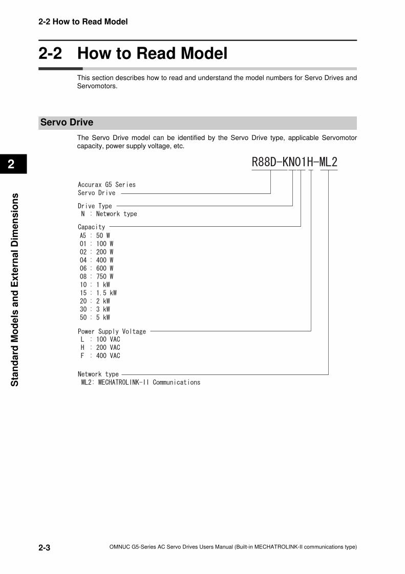
Servo Drive
The Servo Drive model can be identified by the Servo Drive type, applicable Servomotor
capacity, power supply voltage, etc.
2-4
2-2 How to Read Model
OMNUC G5-Series AC Servo Drives Users Manual (Built-in MECHATROLINK-II communications type)
2
Sta
nd
ard
Mo
de
ls a
nd
Ex
tern
al D
ime
ns
ion
s
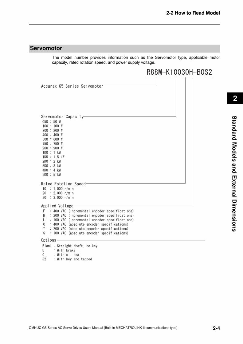
Servomotor
The model number provides information such as the Servomotor type, applicable motor
capacity, rated rotation speed, and power supply voltage.
2-5
2-3 Standard Model List
OMNUC G5-Series AC Servo Drives Users Manual (Built-in MECHATROLINK-II communications type)
2
Sta
nd
ard
Mo
de
ls a
nd
Exte
rnal
Dim
en
sio
ns
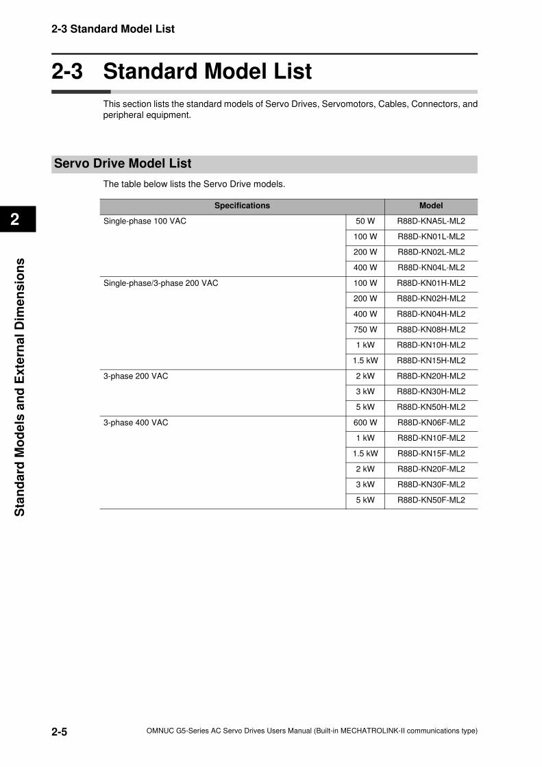
2-3 Standard Model List
This section lists the standard models of Servo Drives, Servomotors, Cables, Connectors, and
peripheral equipment.
Servo Drive Model List
The table below lists the Servo Drive models.
Specifications Model
Single-phase 100 VAC 50 W R88D-KNA5L-ML2
100 W R88D-KN01L-ML2
200 W R88D-KN02L-ML2
400 W R88D-KN04L-ML2
Single-phase/3-phase 200 VAC 100 W R88D-KN01H-ML2
200 W R88D-KN02H-ML2
400 W R88D-KN04H-ML2
750 W R88D-KN08H-ML2
1 kW R88D-KN10H-ML2
1.5 kW R88D-KN15H-ML2
3-phase 200 VAC 2 kW R88D-KN20H-ML2
3 kW R88D-KN30H-ML2
5 kW R88D-KN50H-ML2
3-phase 400 VAC 600 W R88D-KN06F-ML2
1 kW R88D-KN10F-ML2
1.5 kW R88D-KN15F-ML2
2 kW R88D-KN20F-ML2
3 kW R88D-KN30F-ML2
5 kW R88D-KN50F-ML2
2-6
2-3 Standard Model List
OMNUC G5-Series AC Servo Drives Users Manual (Built-in MECHATROLINK-II communications type)
2
Sta
nd
ard
Mo
de
ls a
nd
Ex
tern
al D
ime
ns
ion
s
Servomotor Model List
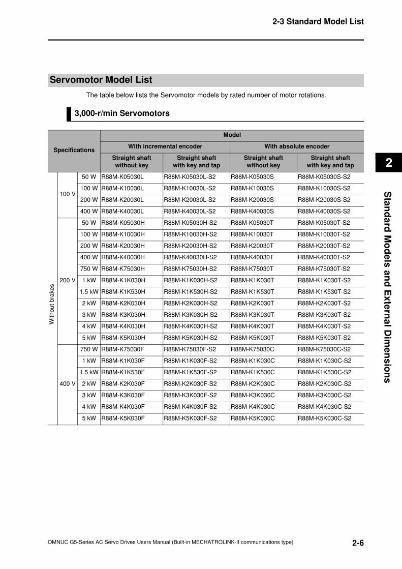
The table below lists the Servomotor models by rated number of motor rotations.
3,000-r/min Servomotors
Specifications
Model
With incremental encoder With absolute encoder
Straight shaft
without key
Straight shaft
with key and tap
Straight shaft
without key
Straight shaft
with key and tap
100 V
50 W R88M-K05030L R88M-K05030L-S2 R88M-K05030S R88M-K05030S-S2
100 W R88M-K10030L R88M-K10030L-S2 R88M-K10030S R88M-K10030S-S2
200 W R88M-K20030L R88M-K20030L-S2 R88M-K20030S R88M-K20030S-S2
400 W R88M-K40030L R88M-K40030L-S2 R88M-K40030S R88M-K40030S-S2
200 V
50 W R88M-K05030H R88M-K05030H-S2 R88M-K05030T R88M-K05030T-S2
100 W R88M-K10030H R88M-K10030H-S2 R88M-K10030T R88M-K10030T-S2
200 W R88M-K20030H R88M-K20030H-S2 R88M-K20030T R88M-K20030T-S2
400 W R88M-K40030H R88M-K40030H-S2 R88M-K40030T R88M-K40030T-S2
750 W R88M-K75030H R88M-K75030H-S2 R88M-K75030T R88M-K75030T-S2
1 kW R88M-K1K030H R88M-K1K030H-S2 R88M-K1K030T R88M-K1K030T-S2
1.5 kW R88M-K1K530H R88M-K1K530H-S2 R88M-K1K530T R88M-K1K530T-S2
2 kW R88M-K2K030H R88M-K2K030H-S2 R88M-K2K030T R88M-K2K030T-S2
3 kW R88M-K3K030H R88M-K3K030H-S2 R88M-K3K030T R88M-K3K030T-S2
4 kW R88M-K4K030H R88M-K4K030H-S2 R88M-K4K030T R88M-K4K030T-S2
5 kW R88M-K5K030H R88M-K5K030H-S2 R88M-K5K030T R88M-K5K030T-S2
400 V
750 W R88M-K75030F R88M-K75030F-S2 R88M-K75030C R88M-K75030C-S2
1 kW R88M-K1K030F R88M-K1K030F-S2 R88M-K1K030C R88M-K1K030C-S2
1.5 kW R88M-K1K530F R88M-K1K530F-S2 R88M-K1K530C R88M-K1K530C-S2
2 kW R88M-K2K030F R88M-K2K030F-S2 R88M-K2K030C R88M-K2K030C-S2
3 kW R88M-K3K030F R88M-K3K030F-S2 R88M-K3K030C R88M-K3K030C-S2
4 kW R88M-K4K030F R88M-K4K030F-S2 R88M-K4K030C R88M-K4K030C-S2
5 kW R88M-K5K030F R88M-K5K030F-S2 R88M-K5K030C R88M-K5K030C-S2
With
ou
t bra
ke
s
2-7
2-3 Standard Model List
OMNUC G5-Series AC Servo Drives Users Manual (Built-in MECHATROLINK-II communications type)
2
Sta
nd
ard
Mo
de
ls a
nd
Exte
rnal
Dim
en
sio
ns
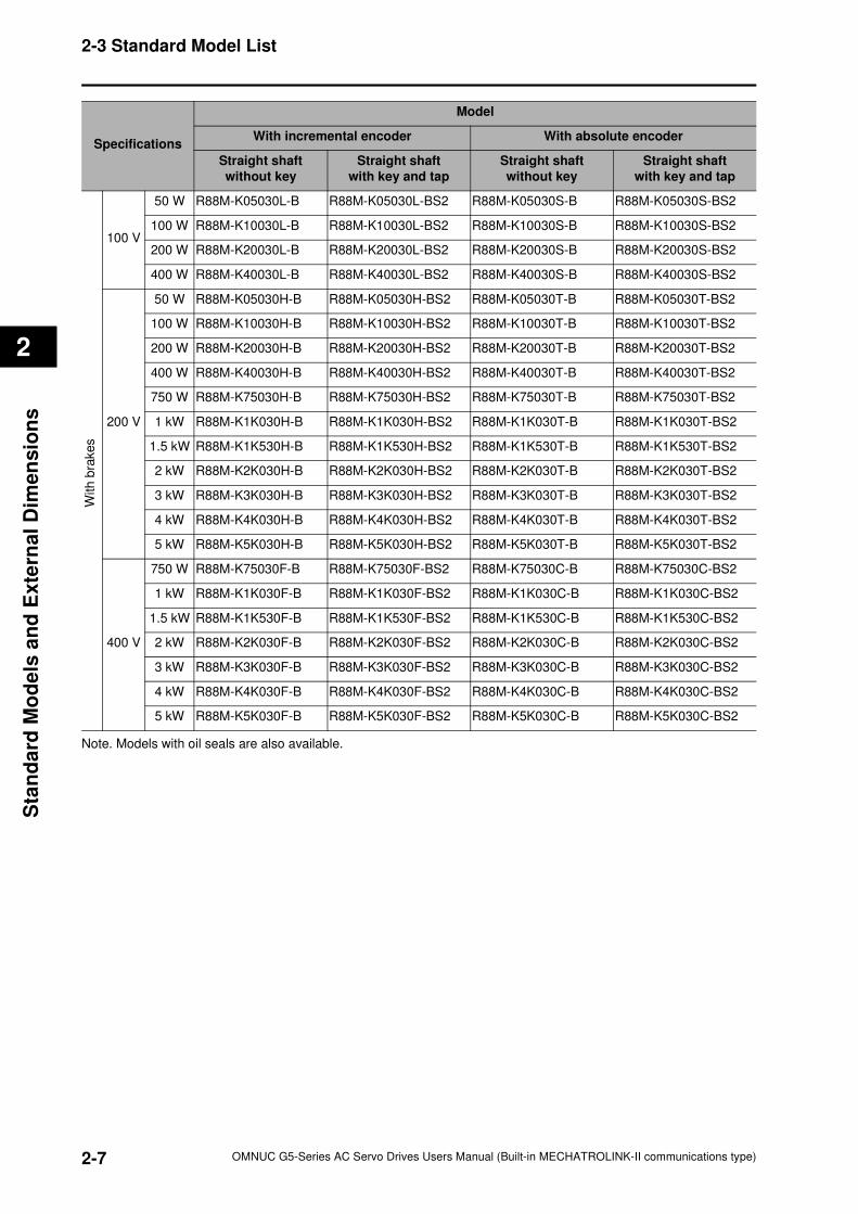
Note. Models with oil seals are also available.
100 V
50 W R88M-K05030L-B R88M-K05030L-BS2 R88M-K05030S-B R88M-K05030S-BS2
100 W R88M-K10030L-B R88M-K10030L-BS2 R88M-K10030S-B R88M-K10030S-BS2
200 W R88M-K20030L-B R88M-K20030L-BS2 R88M-K20030S-B R88M-K20030S-BS2
400 W R88M-K40030L-B R88M-K40030L-BS2 R88M-K40030S-B R88M-K40030S-BS2
200 V
50 W R88M-K05030H-B R88M-K05030H-BS2 R88M-K05030T-B R88M-K05030T-BS2
100 W R88M-K10030H-B R88M-K10030H-BS2 R88M-K10030T-B R88M-K10030T-BS2
200 W R88M-K20030H-B R88M-K20030H-BS2 R88M-K20030T-B R88M-K20030T-BS2
400 W R88M-K40030H-B R88M-K40030H-BS2 R88M-K40030T-B R88M-K40030T-BS2
750 W R88M-K75030H-B R88M-K75030H-BS2 R88M-K75030T-B R88M-K75030T-BS2
1 kW R88M-K1K030H-B R88M-K1K030H-BS2 R88M-K1K030T-B R88M-K1K030T-BS2
1.5 kW R88M-K1K530H-B R88M-K1K530H-BS2 R88M-K1K530T-B R88M-K1K530T-BS2
2 kW R88M-K2K030H-B R88M-K2K030H-BS2 R88M-K2K030T-B R88M-K2K030T-BS2
3 kW R88M-K3K030H-B R88M-K3K030H-BS2 R88M-K3K030T-B R88M-K3K030T-BS2
4 kW R88M-K4K030H-B R88M-K4K030H-BS2 R88M-K4K030T-B R88M-K4K030T-BS2
5 kW R88M-K5K030H-B R88M-K5K030H-BS2 R88M-K5K030T-B R88M-K5K030T-BS2
400 V
750 W R88M-K75030F-B R88M-K75030F-BS2 R88M-K75030C-B R88M-K75030C-BS2
1 kW R88M-K1K030F-B R88M-K1K030F-BS2 R88M-K1K030C-B R88M-K1K030C-BS2
1.5 kW R88M-K1K530F-B R88M-K1K530F-BS2 R88M-K1K530C-B R88M-K1K530C-BS2
2 kW R88M-K2K030F-B R88M-K2K030F-BS2 R88M-K2K030C-B R88M-K2K030C-BS2
3 kW R88M-K3K030F-B R88M-K3K030F-BS2 R88M-K3K030C-B R88M-K3K030C-BS2
4 kW R88M-K4K030F-B R88M-K4K030F-BS2 R88M-K4K030C-B R88M-K4K030C-BS2
5 kW R88M-K5K030F-B R88M-K5K030F-BS2 R88M-K5K030C-B R88M-K5K030C-BS2
Specifications
Model
With incremental encoder With absolute encoder
Straight shaft
without key
Straight shaft
with key and tap
Straight shaft
without key
Straight shaft
with key and tap
With b
rakes
2-8
2-3 Standard Model List
OMNUC G5-Series AC Servo Drives Users Manual (Built-in MECHATROLINK-II communications type)
2
Sta
nd
ard
Mo
de
ls a
nd
Ex
tern
al D
ime
ns
ion
s
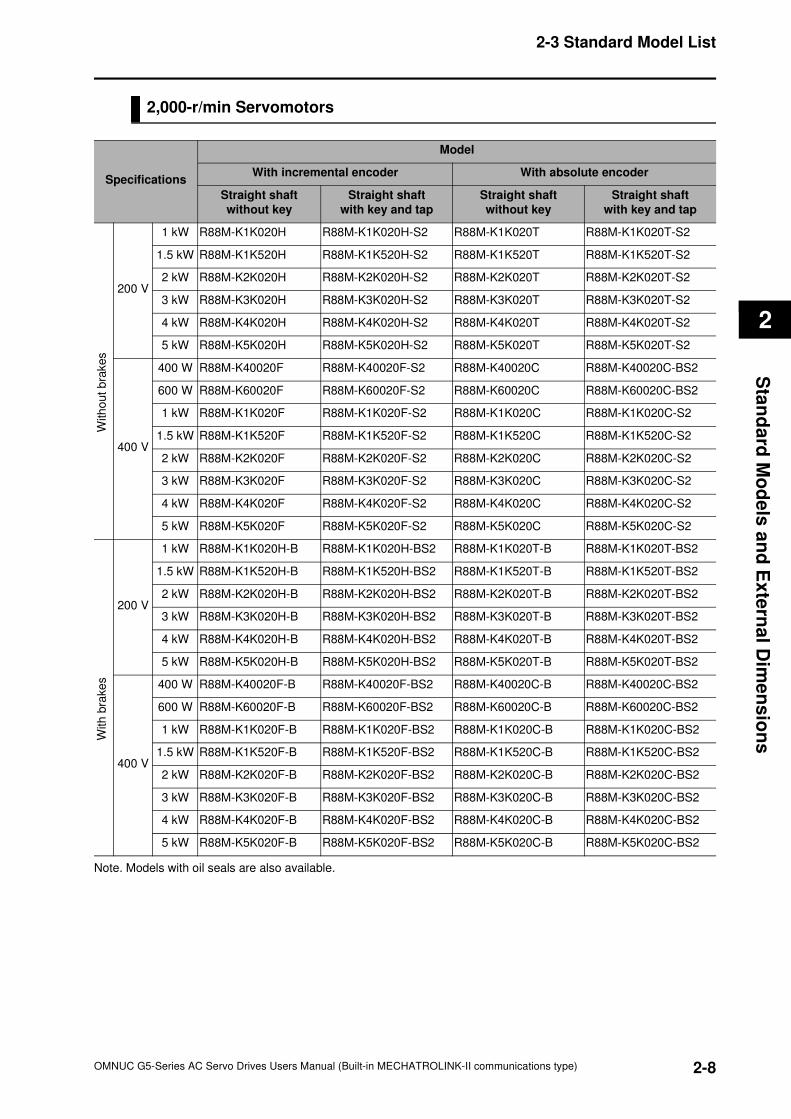
2,000-r/min Servomotors
Note. Models with oil seals are also available.
Specifications
Model
With incremental encoder With absolute encoder
Straight shaft
without key
Straight shaft
with key and tap
Straight shaft
without key
Straight shaft
with key and tap
200 V
1 kW R88M-K1K020H R88M-K1K020H-S2 R88M-K1K020T R88M-K1K020T-S2
1.5 kW R88M-K1K520H R88M-K1K520H-S2 R88M-K1K520T R88M-K1K520T-S2
2 kW R88M-K2K020H R88M-K2K020H-S2 R88M-K2K020T R88M-K2K020T-S2
3 kW R88M-K3K020H R88M-K3K020H-S2 R88M-K3K020T R88M-K3K020T-S2
4 kW R88M-K4K020H R88M-K4K020H-S2 R88M-K4K020T R88M-K4K020T-S2
5 kW R88M-K5K020H R88M-K5K020H-S2 R88M-K5K020T R88M-K5K020T-S2
400 V
400 W R88M-K40020F R88M-K40020F-S2 R88M-K40020C R88M-K40020C-BS2
600 W R88M-K60020F R88M-K60020F-S2 R88M-K60020C R88M-K60020C-BS2
1 kW R88M-K1K020F R88M-K1K020F-S2 R88M-K1K020C R88M-K1K020C-S2
1.5 kW R88M-K1K520F R88M-K1K520F-S2 R88M-K1K520C R88M-K1K520C-S2
2 kW R88M-K2K020F R88M-K2K020F-S2 R88M-K2K020C R88M-K2K020C-S2
3 kW R88M-K3K020F R88M-K3K020F-S2 R88M-K3K020C R88M-K3K020C-S2
4 kW R88M-K4K020F R88M-K4K020F-S2 R88M-K4K020C R88M-K4K020C-S2
5 kW R88M-K5K020F R88M-K5K020F-S2 R88M-K5K020C R88M-K5K020C-S2
200 V
1 kW R88M-K1K020H-B R88M-K1K020H-BS2 R88M-K1K020T-B R88M-K1K020T-BS2
1.5 kW R88M-K1K520H-B R88M-K1K520H-BS2 R88M-K1K520T-B R88M-K1K520T-BS2
2 kW R88M-K2K020H-B R88M-K2K020H-BS2 R88M-K2K020T-B R88M-K2K020T-BS2
3 kW R88M-K3K020H-B R88M-K3K020H-BS2 R88M-K3K020T-B R88M-K3K020T-BS2
4 kW R88M-K4K020H-B R88M-K4K020H-BS2 R88M-K4K020T-B R88M-K4K020T-BS2
5 kW R88M-K5K020H-B R88M-K5K020H-BS2 R88M-K5K020T-B R88M-K5K020T-BS2
400 V
400 W R88M-K40020F-B R88M-K40020F-BS2 R88M-K40020C-B R88M-K40020C-BS2
600 W R88M-K60020F-B R88M-K60020F-BS2 R88M-K60020C-B R88M-K60020C-BS2
1 kW R88M-K1K020F-B R88M-K1K020F-BS2 R88M-K1K020C-B R88M-K1K020C-BS2
1.5 kW R88M-K1K520F-B R88M-K1K520F-BS2 R88M-K1K520C-B R88M-K1K520C-BS2
2 kW R88M-K2K020F-B R88M-K2K020F-BS2 R88M-K2K020C-B R88M-K2K020C-BS2
3 kW R88M-K3K020F-B R88M-K3K020F-BS2 R88M-K3K020C-B R88M-K3K020C-BS2
4 kW R88M-K4K020F-B R88M-K4K020F-BS2 R88M-K4K020C-B R88M-K4K020C-BS2
5 kW R88M-K5K020F-B R88M-K5K020F-BS2 R88M-K5K020C-B R88M-K5K020C-BS2
With
out
bra
kes
With
bra
ke
s
2-9
2-3 Standard Model List
OMNUC G5-Series AC Servo Drives Users Manual (Built-in MECHATROLINK-II communications type)
2
Sta
nd
ard
Mo
de
ls a
nd
Exte
rnal
Dim
en
sio
ns
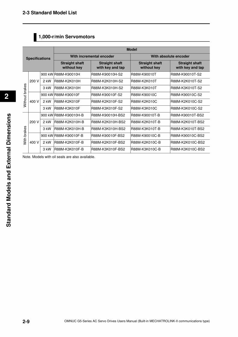
1,000-r/min Servomotors
Note. Models with oil seals are also available.
Specifications
Model
With incremental encoder With absolute encoder
Straight shaft
without key
Straight shaft
with key and tap
Straight shaft
without key
Straight shaft
with key and tap
200 V
900 kW R88M-K90010H R88M-K90010H-S2 R88M-K90010T R88M-K90010T-S2
2 kW R88M-K2K010H R88M-K2K010H-S2 R88M-K2K010T R88M-K2K010T-S2
3 kW R88M-K3K010H R88M-K3K010H-S2 R88M-K3K010T R88M-K3K010T-S2
400 V
900 kW R88M-K90010F R88M-K90010F-S2 R88M-K90010C R88M-K90010C-S2
2 kW R88M-K2K010F R88M-K2K010F-S2 R88M-K2K010C R88M-K2K010C-S2
3 kW R88M-K3K010F R88M-K3K010F-S2 R88M-K3K010C R88M-K3K010C-S2
200 V
900 kW R88M-K90010H-B R88M-K90010H-BS2 R88M-K90010T-B R88M-K90010T-BS2
2 kW R88M-K2K010H-B R88M-K2K010H-BS2 R88M-K2K010T-B R88M-K2K010T-BS2
3 kW R88M-K3K010H-B R88M-K3K010H-BS2 R88M-K3K010T-B R88M-K3K010T-BS2
400 V
900 kW R88M-K90010F-B R88M-K90010F-BS2 R88M-K90010C-B R88M-K90010C-BS2
2 kW R88M-K2K010F-B R88M-K2K010F-BS2 R88M-K2K010C-B R88M-K2K010C-BS2
3 kW R88M-K3K010F-B R88M-K3K010F-BS2 R88M-K3K010C-B R88M-K3K010C-BS2
With
out
bra
kes
With
bra
ke
s
2-10
2-3 Standard Model List
OMNUC G5-Series AC Servo Drives Users Manual (Built-in MECHATROLINK-II communications type)
2
Sta
nd
ard
Mo
de
ls a
nd
Ex
tern
al D
ime
ns
ion
s
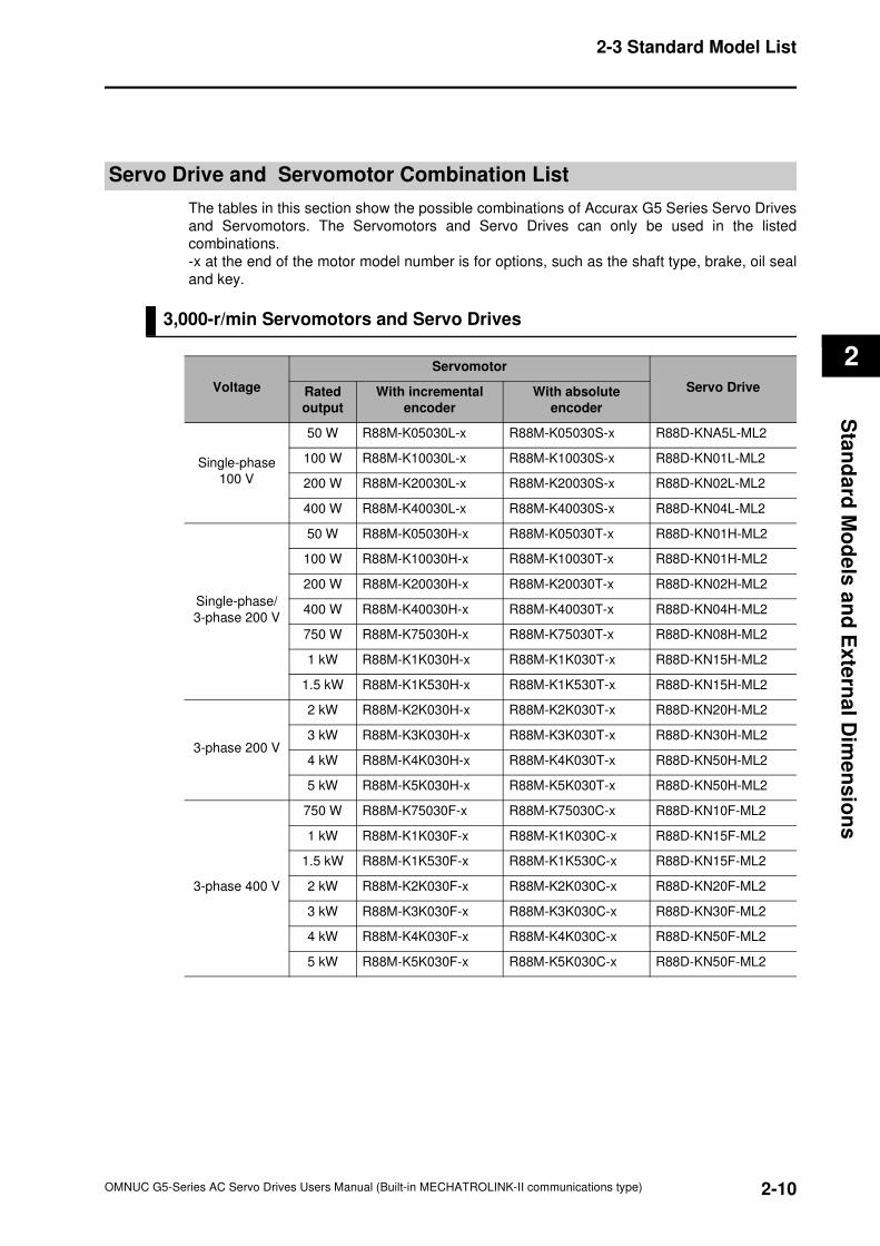
Servo Drive and Servomotor Combination List
The tables in this section show the possible combinations of Accurax G5 Series Servo Drives
and Servomotors. The Servomotors and Servo Drives can only be used in the listed
combinations.
-x at the end of the motor model number is for options, such as the shaft type, brake, oil seal
and key.
3,000-r/min Servomotors and Servo Drives
Voltage
Servomotor
Servo DriveRated
output
With incremental
encoder
With absolute
encoder
Single-phase
100 V
50 W R88M-K05030L-x R88M-K05030S-x R88D-KNA5L-ML2
100 W R88M-K10030L-x R88M-K10030S-x R88D-KN01L-ML2
200 W R88M-K20030L-x R88M-K20030S-x R88D-KN02L-ML2
400 W R88M-K40030L-x R88M-K40030S-x R88D-KN04L-ML2
Single-phase/
3-phase 200 V
50 W R88M-K05030H-x R88M-K05030T-x R88D-KN01H-ML2
100 W R88M-K10030H-x R88M-K10030T-x R88D-KN01H-ML2
200 W R88M-K20030H-x R88M-K20030T-x R88D-KN02H-ML2
400 W R88M-K40030H-x R88M-K40030T-x R88D-KN04H-ML2
750 W R88M-K75030H-x R88M-K75030T-x R88D-KN08H-ML2
1 kW R88M-K1K030H-x R88M-K1K030T-x R88D-KN15H-ML2
1.5 kW R88M-K1K530H-x R88M-K1K530T-x R88D-KN15H-ML2
3-phase 200 V
2 kW R88M-K2K030H-x R88M-K2K030T-x R88D-KN20H-ML2
3 kW R88M-K3K030H-x R88M-K3K030T-x R88D-KN30H-ML2
4 kW R88M-K4K030H-x R88M-K4K030T-x R88D-KN50H-ML2
5 kW R88M-K5K030H-x R88M-K5K030T-x R88D-KN50H-ML2
3-phase 400 V
750 W R88M-K75030F-x R88M-K75030C-x R88D-KN10F-ML2
1 kW R88M-K1K030F-x R88M-K1K030C-x R88D-KN15F-ML2
1.5 kW R88M-K1K530F-x R88M-K1K530C-x R88D-KN15F-ML2
2 kW R88M-K2K030F-x R88M-K2K030C-x R88D-KN20F-ML2
3 kW R88M-K3K030F-x R88M-K3K030C-x R88D-KN30F-ML2
4 kW R88M-K4K030F-x R88M-K4K030C-x R88D-KN50F-ML2
5 kW R88M-K5K030F-x R88M-K5K030C-x R88D-KN50F-ML2
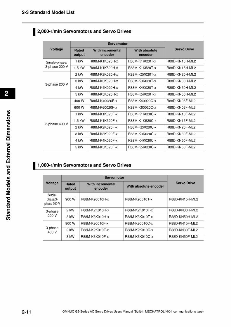
2-11
2-3 Standard Model List
OMNUC G5-Series AC Servo Drives Users Manual (Built-in MECHATROLINK-II communications type)
2
Sta
nd
ard
Mo
de
ls a
nd
Exte
rnal
Dim
en
sio
ns
2,000-r/min Servomotors and Servo Drives
1,000-r/min Servomotors and Servo Drives
Voltage
Servomotor
Servo DriveRated
output
With incremental
encoder
With absolute
encoder
Single-phase/
3-phase 200 V
1 kW R88M-K1K020H-x R88M-K1K020T-x R88D-KN10H-ML2
1.5 kW R88M-K1K520H-x R88M-K1K520T-x R88D-KN15H-ML2
3-phase 200 V
2 kW R88M-K2K020H-x R88M-K2K020T-x R88D-KN20H-ML2
3 kW R88M-K3K020H-x R88M-K3K020T-x R88D-KN30H-ML2
4 kW R88M-K4K020H-x R88M-K4K020T-x R88D-KN50H-ML2
5 kW R88M-K5K020H-x R88M-K5K020T-x R88D-KN50H-ML2
3-phase 400 V
400 W R88M-K40020F-x R88M-K40020C-x R88D-KN06F-ML2
600 W R88M-K60020F-x R88M-K60020C-x R88D-KN06F-ML2
1 kW R88M-K1K020F-x R88M-K1K020C-x R88D-KN10F-ML2
1.5 kW R88M-K1K520F-x R88M-K1K520C-x R88D-KN15F-ML2
2 kW R88M-K2K020F-x R88M-K2K020C-x R88D-KN20F-ML2
3 kW R88M-K3K020F-x R88M-K3K020C-x R88D-KN30F-ML2
4 kW R88M-K4K020F-x R88M-K4K020C-x R88D-KN50F-ML2
5 kW R88M-K5K020F-x R88M-K5K020C-x R88D-KN50F-ML2
Voltage
Servomotor
Servo DriveRated
output
With incremental
encoderWith absolute encoder
Single-
phase/3-
phase 200 V
900 W R88M-K90010H-x R88M-K90010T-x R88D-KN15H-ML2
3-phase
200 V
2 kW R88M-K2K010H-x R88M-K2K010T-x R88D-KN30H-ML2
3 kW R88M-K3K010H-x R88M-K3K010T-x R88D-KN50H-ML2
3-phase
400 V
900 W R88M-K90010F-x R88M-K90010C-x R88D-KN15F-ML2
2 kW R88M-K2K010F-x R88M-K2K010C-x R88D-KN30F-ML2
3 kW R88M-K3K010F-x R88M-K3K010C-x R88D-KN50F-ML2
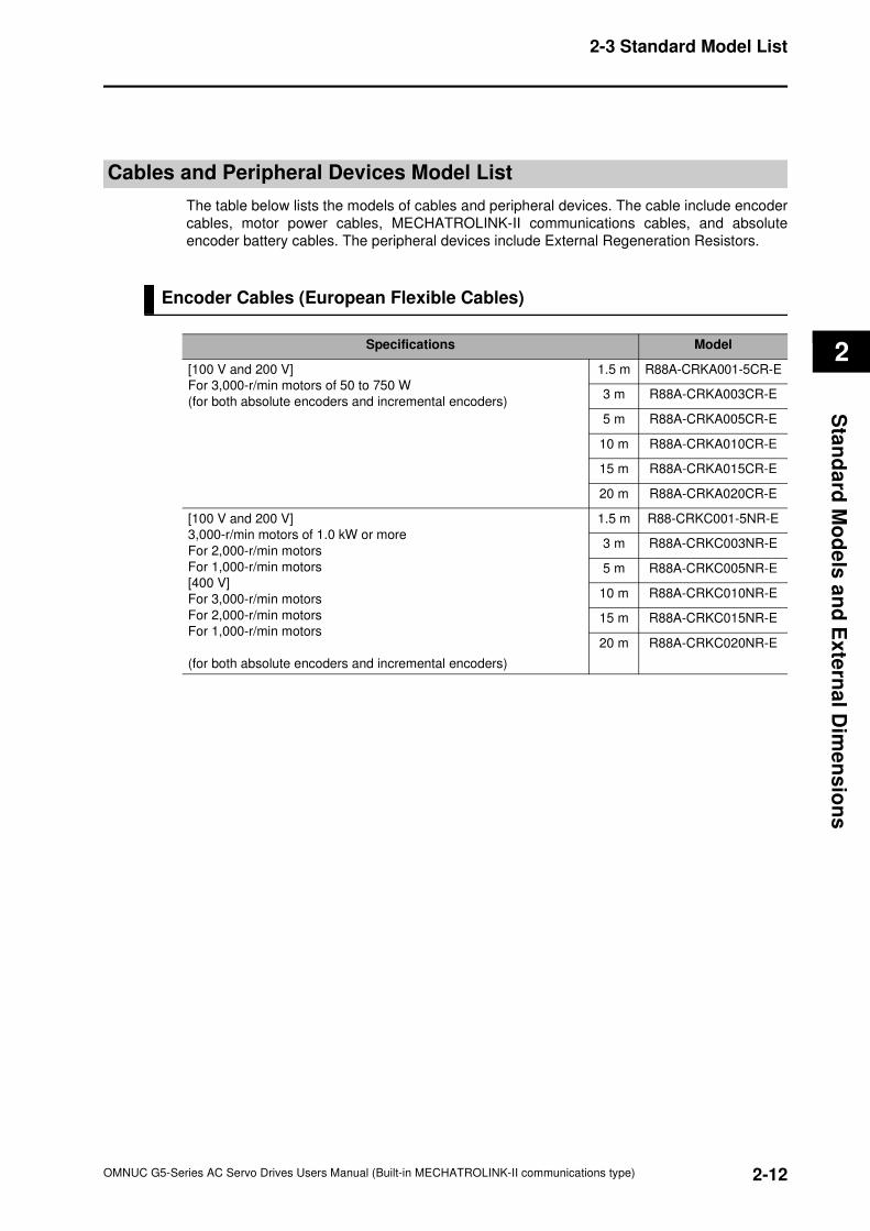
2-12
2-3 Standard Model List
OMNUC G5-Series AC Servo Drives Users Manual (Built-in MECHATROLINK-II communications type)
2
Sta
nd
ard
Mo
de
ls a
nd
Ex
tern
al D
ime
ns
ion
s
Cables and Peripheral Devices Model List
The table below lists the models of cables and peripheral devices. The cable include encoder
cables, motor power cables, MECHATROLINK-II communications cables, and absolute
encoder battery cables. The peripheral devices include External Regeneration Resistors.
Encoder Cables (European Flexible Cables)
Specifications Model
[100 V and 200 V]
For 3,000-r/min motors of 50 to 750 W
(for both absolute encoders and incremental encoders)
1.5 m R88A-CRKA001-5CR-E
3 m R88A-CRKA003CR-E
5 m R88A-CRKA005CR-E
10 m R88A-CRKA010CR-E
15 m R88A-CRKA015CR-E
20 m R88A-CRKA020CR-E
[100 V and 200 V]
3,000-r/min motors of 1.0 kW or more
For 2,000-r/min motors
For 1,000-r/min motors
[400 V]
For 3,000-r/min motors
For 2,000-r/min motors
For 1,000-r/min motors
(for both absolute encoders and incremental encoders)
1.5 m R88-CRKC001-5NR-E
3 m R88A-CRKC003NR-E
5 m R88A-CRKC005NR-E
10 m R88A-CRKC010NR-E
15 m R88A-CRKC015NR-E
20 m R88A-CRKC020NR-E
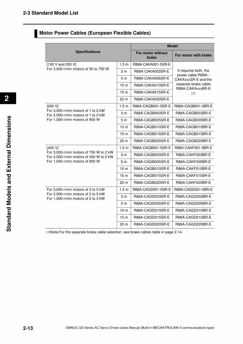
2-13
2-3 Standard Model List
OMNUC G5-Series AC Servo Drives Users Manual (Built-in MECHATROLINK-II communications type)
2
Sta
nd
ard
Mo
de
ls a
nd
Exte
rnal
Dim
en
sio
ns
Motor Power Cables (European Flexible Cables)
(1)Note.For the separate brake cable selection, see brake cables table in page 2-14.
Specifications
Model
For motor without
brakeFor motor with brake
[100 V and 200 V]
For 3,000-r/min motors of 50 to 750 W
1.5 m R88A-CAKA001-5SR-E
It requires both, the
power cable R88A--
CAKAxxxSR-E and the
separate brake cable
R88A-CAKAxxxBR-E
(1)
3 m R88A-CAKA003SR-E
5 m R88A-CAKA005SR-E
10 m R88A-CAKA010SR-E
15 m R88A-CAKA015SR-E
20 m R88A-CAKA020SR-E
[200 V]
For 3,000-r/min motors of 1 to 2 kW
For 2,000-r/min motors of 1 to 2 kW
For 1,000-r/min motors of 900 W
1.5 m R88A-CAGB001-5SR-E R88A-CAGB001-5BR-E
3 m R88A-CAGB003SR-E R88A-CAGB003BR-E
5 m R88A-CAGB005SR-E R88A-CAGB005BR-E
10 m R88A-CAGB010SR-E R88A-CAGB010BR-E
15 m R88A-CAGB015SR-E R88A-CAGB015BR-E
20 m R88A-CAGB020SR-E R88A-CAGB020BR-E
[400 V]
For 3,000-r/min motors of 750 W to 2 kW
For 2,000-r/min motors of 400 W to 2 kW
For 1,000-r/min motors of 900 W
1.5 m R88A-CAGB001-5SR-E R88A-CAKF001-5BR-E
3 m R88A-CAGB003SR-E R88A-CAKF003BR-E
5 m R88A-CAGB005SR-E R88A-CAKF005BR-E
10 m R88A-CAGB010SR-E R88A-CAKF010BR-E
15 m R88A-CAGB015SR-E R88A-CAKF015BR-E
20 m R88A-CAGB020SR-E R88A-CAKF020BR-E
For 3,000-r/min motors of 3 to 5 kW
For 2,000-r/min motors of 3 to 5 kW
For 1,000-r/min motors of 2 to 3 kW
1.5 m R88A-CAGD001-5SR-E R88A-CAGD001-5BR-E
3 m R88A-CAGD003SR-E R88A-CAGD003BR-E
5 m R88A-CAGD005SR-E R88A-CAGD005BR-E
10 m R88A-CAGD010SR-E R88A-CAGD010BR-E
15 m R88A-CAGD015SR-E R88A-CAGD015BR-E
20 m R88A-CAGD020SR-E R88A-CAGD020BR-E
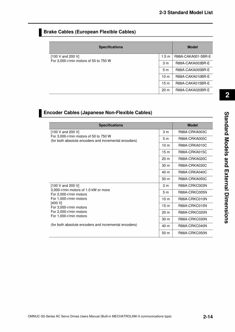
2-14
2-3 Standard Model List
OMNUC G5-Series AC Servo Drives Users Manual (Built-in MECHATROLINK-II communications type)
2
Sta
nd
ard
Mo
de
ls a
nd
Ex
tern
al D
ime
ns
ion
s
Brake Cables (European Flexible Cables)
Encoder Cables (Japanese Non-Flexible Cables)
Specifications Model
[100 V and 200 V]
For 3,000-r/min motors of 50 to 750 W
1.5 m R88A-CAKA001-5BR-E
3 m R88A-CAKA003BR-E
5 m R88A-CAKA005BR-E
10 m R88A-CAKA010BR-E
15 m R88A-CAKA015BR-E
20 m R88A-CAKA020BR-E
Specifications Model
[100 V and 200 V]
For 3,000-r/min motors of 50 to 750 W
(for both absolute encoders and incremental encoders)
3 m R88A-CRKA003C
5 m R88A-CRKA005C
10 m R88A-CRKA010C
15 m R88A-CRKA015C
20 m R88A-CRKA020C
30 m R88A-CRKA030C
40 m R88A-CRKA040C
50 m R88A-CRKA050C
[100 V and 200 V]
3,000-r/min motors of 1.0 kW or more
For 2,000-r/min motors
For 1,000-r/min motors
[400 V]
For 3,000-r/min motors
For 2,000-r/min motors
For 1,000-r/min motors
(for both absolute encoders and incremental encoders)
3 m R88A-CRKC003N
5 m R88A-CRKC005N
10 m R88A-CRKC010N
15 m R88A-CRKC015N
20 m R88A-CRKC020N
30 m R88A-CRKC030N
40 m R88A-CRKC040N
50 m R88A-CRKC050N

2-15
2-3 Standard Model List
OMNUC G5-Series AC Servo Drives Users Manual (Built-in MECHATROLINK-II communications type)
2
Sta
nd
ard
Mo
de
ls a
nd
Exte
rnal
Dim
en
sio
ns
Motor Power Cables (Japanese Non-Flexible Cables)
(1)Note.For the separate brake cable selection, see brake cables table in page 2-16.
Specifications
Model
For motor without
brakeFor motor with brake
[100 V and 200 V]
For 3,000-r/min motors of 50 to 750 W
3 m R88A-CAKA003S
It requires both, the
power cable R88A--
CAKAxxxS and the
separate brake cable
R88A-CAKAxxxB (1)
5 m R88A-CAKA005S
10 m R88A-CAKA010S
15 m R88A-CAKA015S
20 m R88A-CAKA020S
30 m R88A-CAKA030S
40 m R88A-CAKA040S
50 m R88A-CAKA050S
[200 V]
For 3,000-r/min motors of 1 to 2 kW
For 2,000-r/min motors of 1 to 2 kW
For 1,000-r/min motors of 900 W
3 m R88A-CAGB003S R88A-CAGB003B
5 m R88A-CAGB005S R88A-CAGB005B
10 m R88A-CAGB010S R88A-CAGB010B
15 m R88A-CAGB015S R88A-CAGB015B
20 m R88A-CAGB020S R88A-CAGB020B
30 m R88A-CAGB030S R88A-CAGB030B
40 m R88A-CAGB040S R88A-CAGB040B
50 m R88A-CAGB050S R88A-CAGB050B
[400 V]
For 3,000-r/min motors of 750 W to 2 kW
For 2,000-r/min motors of 400 W to 2 kW
For 1,000-r/min motors of 900 W
3 m R88A-CAGB003S R88A-CAKF003B
5 m R88A-CAGB005S R88A-CAKF005B
10 m R88A-CAGB010S R88A-CAKF010B
15 m R88A-CAGB015S R88A-CAKF015B
20 m R88A-CAGB020S R88A-CAKF020B
30 m R88A-CAGB030S R88A-CAKF030B
40 m R88A-CAGB040S R88A-CAKF040B
50 m R88A-CAGB050S R88A-CAKF050B
For 3,000-r/min motors of 3 to 5 kW
For 2,000-r/min motors of 3 to 5 kW
For 1,000-r/min motors of 2 to 3 kW
3 m R88A-CAGD003S R88A-CAGD003B
5 m R88A-CAGD005S R88A-CAGD005B
10 m R88A-CAGD010S R88A-CAGD010B
15 m R88A-CAGD015S R88A-CAGD015B
20 m R88A-CAGD020S R88A-CAGD020B
30 m R88A-CAGD030S R88A-CAGD030B
40 m R88A-CAGD040S R88A-CAGD040B
50 m R88A-CAGD050S R88A-CAGD050B
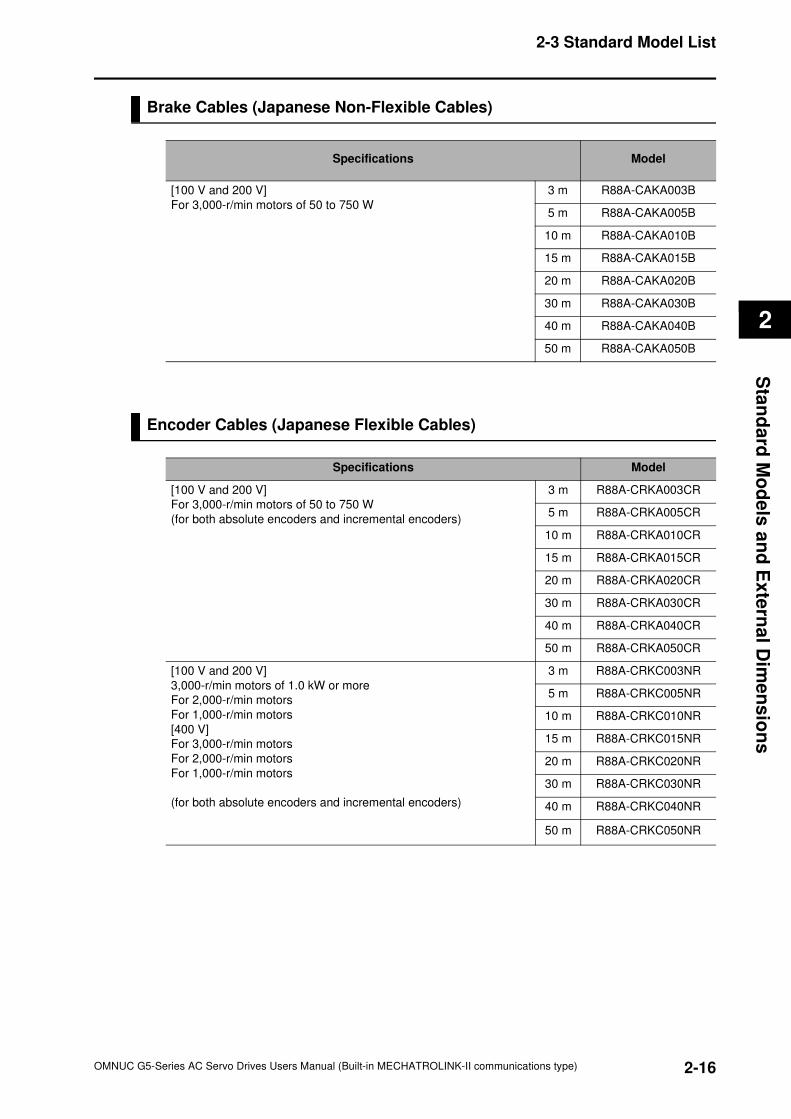
2-16
2-3 Standard Model List
OMNUC G5-Series AC Servo Drives Users Manual (Built-in MECHATROLINK-II communications type)
2
Sta
nd
ard
Mo
de
ls a
nd
Ex
tern
al D
ime
ns
ion
s
Brake Cables (Japanese Non-Flexible Cables)
Encoder Cables (Japanese Flexible Cables)
Specifications Model
[100 V and 200 V]
For 3,000-r/min motors of 50 to 750 W
3 m R88A-CAKA003B
5 m R88A-CAKA005B
10 m R88A-CAKA010B
15 m R88A-CAKA015B
20 m R88A-CAKA020B
30 m R88A-CAKA030B
40 m R88A-CAKA040B
50 m R88A-CAKA050B
Specifications Model
[100 V and 200 V]
For 3,000-r/min motors of 50 to 750 W
(for both absolute encoders and incremental encoders)
3 m R88A-CRKA003CR
5 m R88A-CRKA005CR
10 m R88A-CRKA010CR
15 m R88A-CRKA015CR
20 m R88A-CRKA020CR
30 m R88A-CRKA030CR
40 m R88A-CRKA040CR
50 m R88A-CRKA050CR
[100 V and 200 V]
3,000-r/min motors of 1.0 kW or more
For 2,000-r/min motors
For 1,000-r/min motors
[400 V]
For 3,000-r/min motors
For 2,000-r/min motors
For 1,000-r/min motors
(for both absolute encoders and incremental encoders)
3 m R88A-CRKC003NR
5 m R88A-CRKC005NR
10 m R88A-CRKC010NR
15 m R88A-CRKC015NR
20 m R88A-CRKC020NR
30 m R88A-CRKC030NR
40 m R88A-CRKC040NR
50 m R88A-CRKC050NR
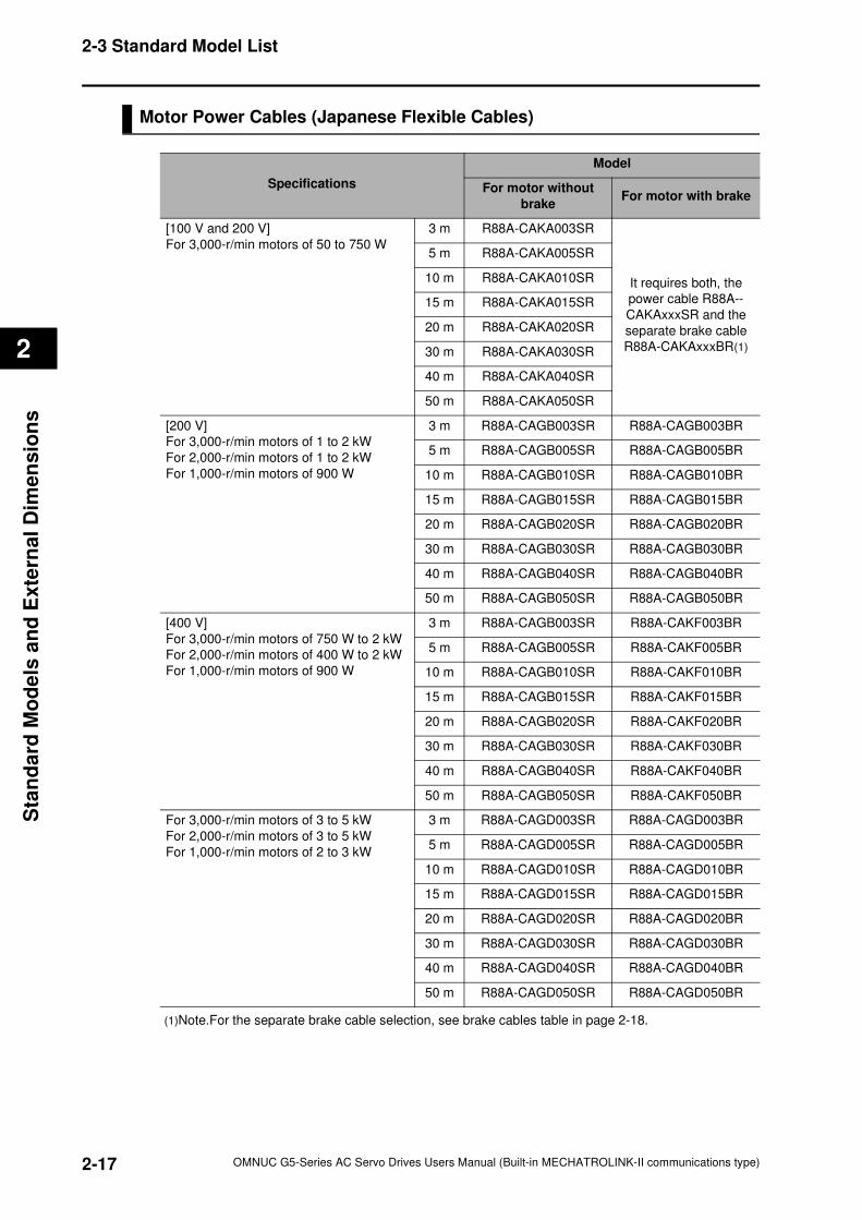
2-17
2-3 Standard Model List
OMNUC G5-Series AC Servo Drives Users Manual (Built-in MECHATROLINK-II communications type)
2
Sta
nd
ard
Mo
de
ls a
nd
Exte
rnal
Dim
en
sio
ns
Motor Power Cables (Japanese Flexible Cables)
(1)Note.For the separate brake cable selection, see brake cables table in page 2-18.
Specifications
Model
For motor without
brakeFor motor with brake
[100 V and 200 V]
For 3,000-r/min motors of 50 to 750 W
3 m R88A-CAKA003SR
It requires both, the
power cable R88A--
CAKAxxxSR and the
separate brake cable
R88A-CAKAxxxBR(1)
5 m R88A-CAKA005SR
10 m R88A-CAKA010SR
15 m R88A-CAKA015SR
20 m R88A-CAKA020SR
30 m R88A-CAKA030SR
40 m R88A-CAKA040SR
50 m R88A-CAKA050SR
[200 V]
For 3,000-r/min motors of 1 to 2 kW
For 2,000-r/min motors of 1 to 2 kW
For 1,000-r/min motors of 900 W
3 m R88A-CAGB003SR R88A-CAGB003BR
5 m R88A-CAGB005SR R88A-CAGB005BR
10 m R88A-CAGB010SR R88A-CAGB010BR
15 m R88A-CAGB015SR R88A-CAGB015BR
20 m R88A-CAGB020SR R88A-CAGB020BR
30 m R88A-CAGB030SR R88A-CAGB030BR
40 m R88A-CAGB040SR R88A-CAGB040BR
50 m R88A-CAGB050SR R88A-CAGB050BR
[400 V]
For 3,000-r/min motors of 750 W to 2 kW
For 2,000-r/min motors of 400 W to 2 kW
For 1,000-r/min motors of 900 W
3 m R88A-CAGB003SR R88A-CAKF003BR
5 m R88A-CAGB005SR R88A-CAKF005BR
10 m R88A-CAGB010SR R88A-CAKF010BR
15 m R88A-CAGB015SR R88A-CAKF015BR
20 m R88A-CAGB020SR R88A-CAKF020BR
30 m R88A-CAGB030SR R88A-CAKF030BR
40 m R88A-CAGB040SR R88A-CAKF040BR
50 m R88A-CAGB050SR R88A-CAKF050BR
For 3,000-r/min motors of 3 to 5 kW
For 2,000-r/min motors of 3 to 5 kW
For 1,000-r/min motors of 2 to 3 kW
3 m R88A-CAGD003SR R88A-CAGD003BR
5 m R88A-CAGD005SR R88A-CAGD005BR
10 m R88A-CAGD010SR R88A-CAGD010BR
15 m R88A-CAGD015SR R88A-CAGD015BR
20 m R88A-CAGD020SR R88A-CAGD020BR
30 m R88A-CAGD030SR R88A-CAGD030BR
40 m R88A-CAGD040SR R88A-CAGD040BR
50 m R88A-CAGD050SR R88A-CAGD050BR
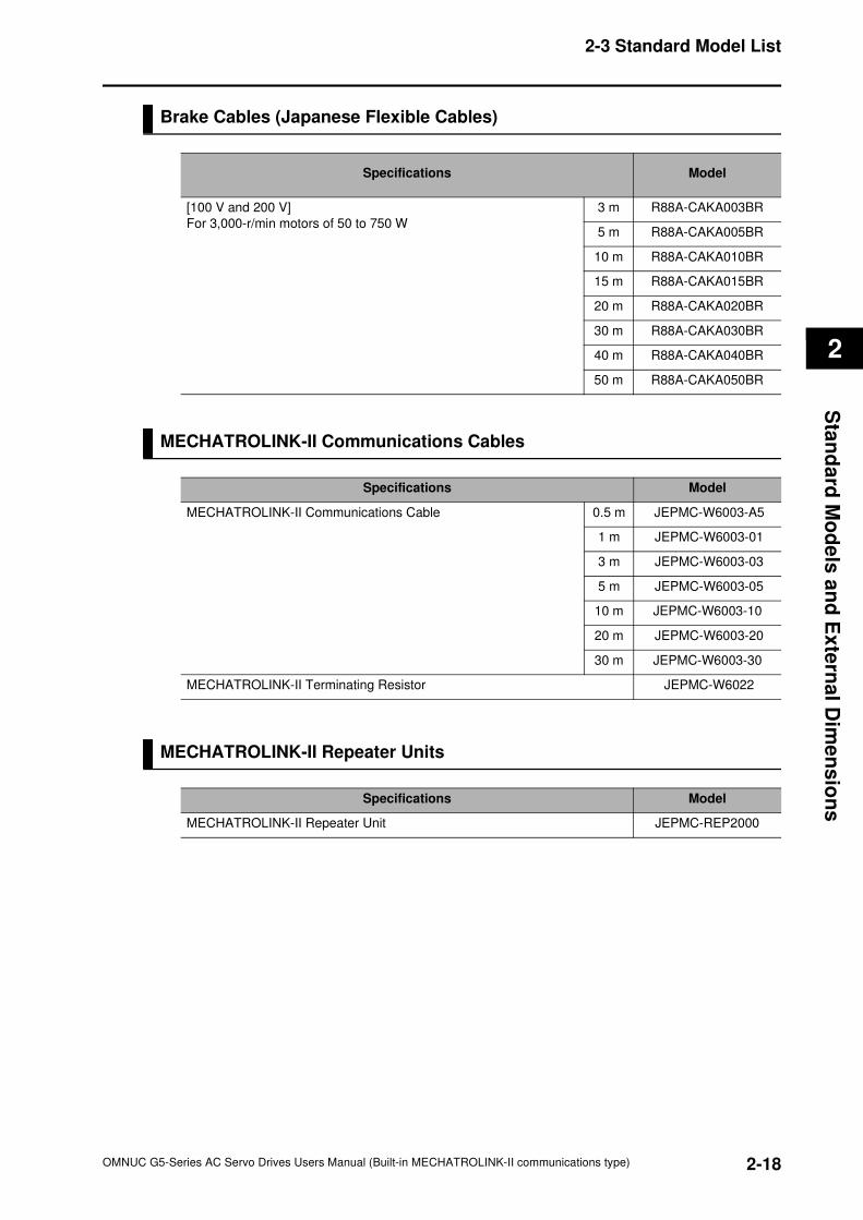
2-18
2-3 Standard Model List
OMNUC G5-Series AC Servo Drives Users Manual (Built-in MECHATROLINK-II communications type)
2
Sta
nd
ard
Mo
de
ls a
nd
Ex
tern
al D
ime
ns
ion
s
Brake Cables (Japanese Flexible Cables)
MECHATROLINK-II Communications Cables
MECHATROLINK-II Repeater Units
Specifications Model
[100 V and 200 V]
For 3,000-r/min motors of 50 to 750 W
3 m R88A-CAKA003BR
5 m R88A-CAKA005BR
10 m R88A-CAKA010BR
15 m R88A-CAKA015BR
20 m R88A-CAKA020BR
30 m R88A-CAKA030BR
40 m R88A-CAKA040BR
50 m R88A-CAKA050BR
Specifications Model
MECHATROLINK-II Communications Cable 0.5 m JEPMC-W6003-A5
1 m JEPMC-W6003-01
3 m JEPMC-W6003-03
5 m JEPMC-W6003-05
10 m JEPMC-W6003-10
20 m JEPMC-W6003-20
30 m JEPMC-W6003-30
MECHATROLINK-II Terminating Resistor JEPMC-W6022
Specifications Model
MECHATROLINK-II Repeater Unit JEPMC-REP2000
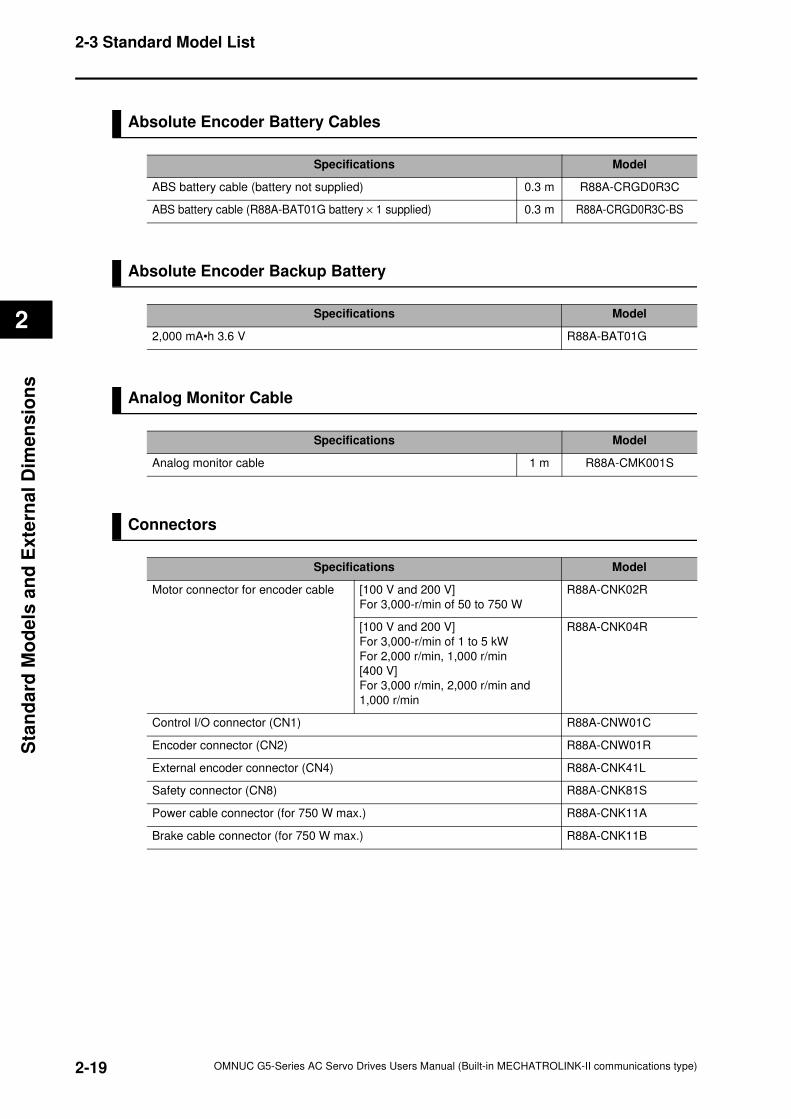
2-19
2-3 Standard Model List
OMNUC G5-Series AC Servo Drives Users Manual (Built-in MECHATROLINK-II communications type)
2
Sta
nd
ard
Mo
de
ls a
nd
Exte
rnal
Dim
en
sio
ns
Absolute Encoder Battery Cables
Absolute Encoder Backup Battery
Analog Monitor Cable
Connectors
Specifications Model
ABS battery cable (battery not supplied) 0.3 m R88A-CRGD0R3C
ABS battery cable (R88A-BAT01G battery × 1 supplied) 0.3 m R88A-CRGD0R3C-BS
Specifications Model
2,000 mA•h 3.6 V R88A-BAT01G
Specifications Model
Analog monitor cable 1 m R88A-CMK001S
Specifications Model
Motor connector for encoder cable [100 V and 200 V]
For 3,000-r/min of 50 to 750 W
R88A-CNK02R
[100 V and 200 V]
For 3,000-r/min of 1 to 5 kW
For 2,000 r/min, 1,000 r/min
[400 V]
For 3,000 r/min, 2,000 r/min and
1,000 r/min
R88A-CNK04R
Control I/O connector (CN1) R88A-CNW01C
Encoder connector (CN2) R88A-CNW01R
External encoder connector (CN4) R88A-CNK41L
Safety connector (CN8) R88A-CNK81S
Power cable connector (for 750 W max.) R88A-CNK11A
Brake cable connector (for 750 W max.) R88A-CNK11B
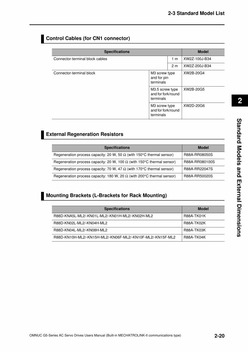
2-20
2-3 Standard Model List
OMNUC G5-Series AC Servo Drives Users Manual (Built-in MECHATROLINK-II communications type)
2
Sta
nd
ard
Mo
de
ls a
nd
Ex
tern
al D
ime
ns
ion
s
Control Cables (for CN1 connector)
External Regeneration Resistors
Mounting Brackets (L-Brackets for Rack Mounting)
Specifications Model
Connector-terminal block cables 1 m XW2Z-100J-B34
2 m XW2Z-200J-B34
Connector-terminal block M3 screw type
and for pin
terminals
XW2B-20G4
M3.5 screw type
and for fork/round
terminals
XW2B-20G5
M3 screw type
and for fork/round
terminals
XW2D-20G6
Specifications Model
Regeneration process capacity: 20 W, 50 Ω (with 150°C thermal sensor) R88A-RR08050S
Regeneration process capacity: 20 W, 100 Ω (with 150°C thermal sensor) R88A-RR080100S
Regeneration process capacity: 70 W, 47 Ω (with 170°C thermal sensor) R88A-RR22047S
Regeneration process capacity: 180 W, 20 Ω (with 200°C thermal sensor) R88A-RR50020S
Specifications Model
R88D-KNA5L-ML2/-KN01L-ML2/-KN01H-ML2/-KN02H-ML2 R88A-TK01K
R88D-KN02L-ML2/-KN04H-ML2 R88A-TK02K
R88D-KN04L-ML2/-KN08H-ML2 R88A-TK03K
R88D-KN10H-ML2/-KN15H-ML2/-KN06F-ML2/-KN10F-ML2/-KN15F-ML2 R88A-TK04K
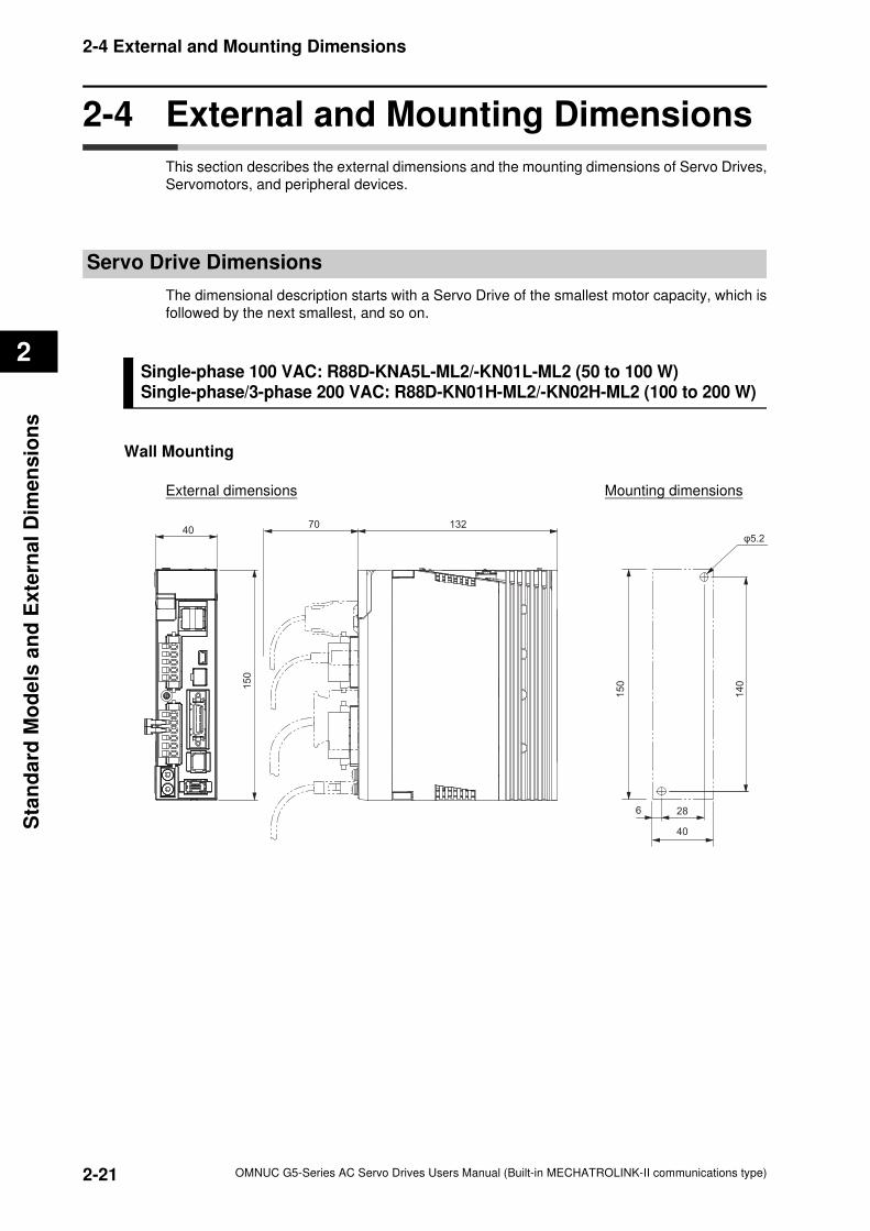
2-21
2-4 External and Mounting Dimensions
OMNUC G5-Series AC Servo Drives Users Manual (Built-in MECHATROLINK-II communications type)
2
Sta
nd
ard
Mo
de
ls a
nd
Exte
rnal
Dim
en
sio
ns
2-4 External and Mounting Dimensions
This section describes the external dimensions and the mounting dimensions of Servo Drives,
Servomotors, and peripheral devices.
Servo Drive Dimensions
The dimensional description starts with a Servo Drive of the smallest motor capacity, which is
followed by the next smallest, and so on.
Single-phase 100 VAC: R88D-KNA5L-ML2/-KN01L-ML2 (50 to 100 W) Single-phase/3-phase 200 VAC: R88D-KN01H-ML2/-KN02H-ML2 (100 to 200 W)
Wall Mounting
External dimensions Mounting dimensions
1327040
150
40
286
150
140
φ5.2
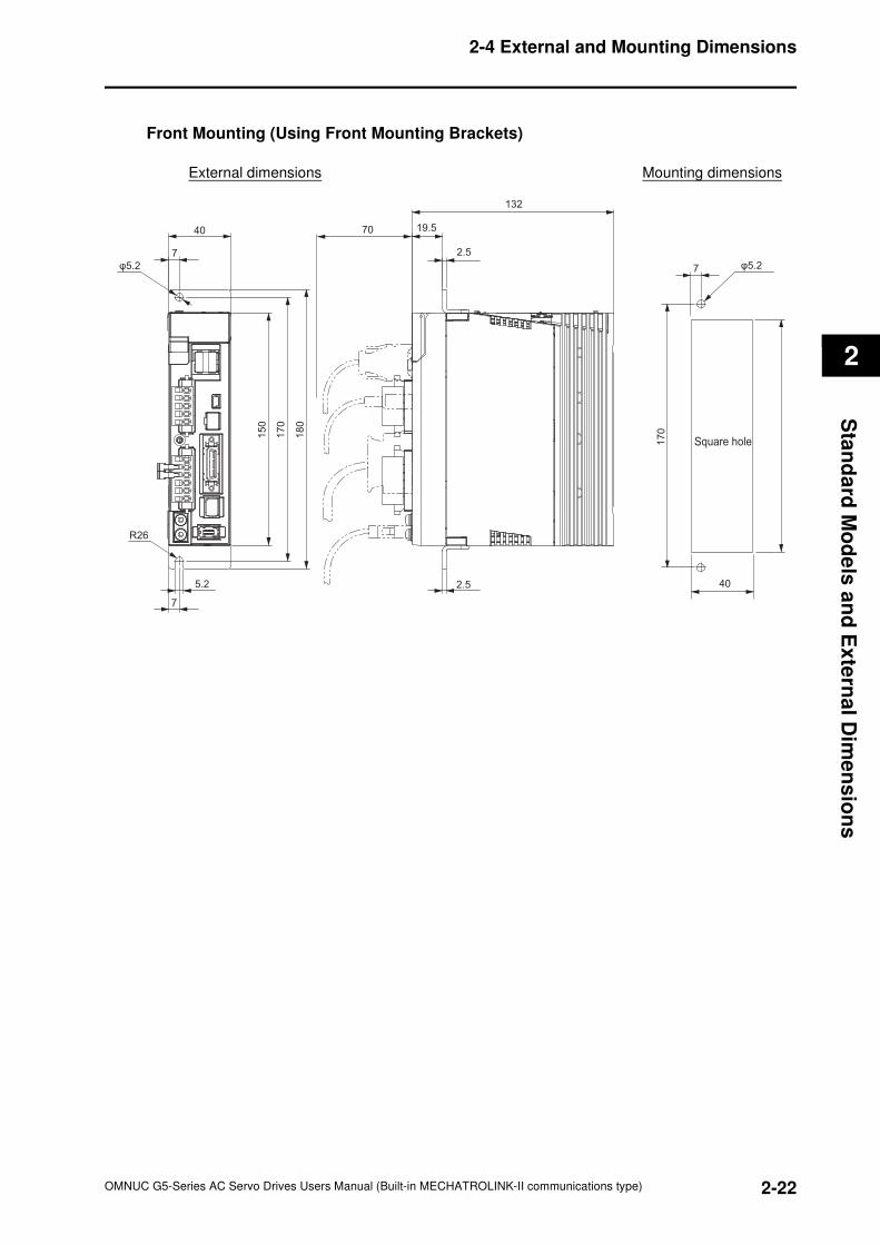
2-22
2-4 External and Mounting Dimensions
OMNUC G5-Series AC Servo Drives Users Manual (Built-in MECHATROLINK-II communications type)
2
Sta
nd
ard
Mo
de
ls a
nd
Ex
tern
al D
ime
ns
ion
s
Front Mounting (Using Front Mounting Brackets)
External dimensions Mounting dimensions
40
7
18
0
17
0
15
0
5.2
R26
7
φ5.2
2.5
132
19.5
2.5
40
7 φ5.2
70
Square hole170
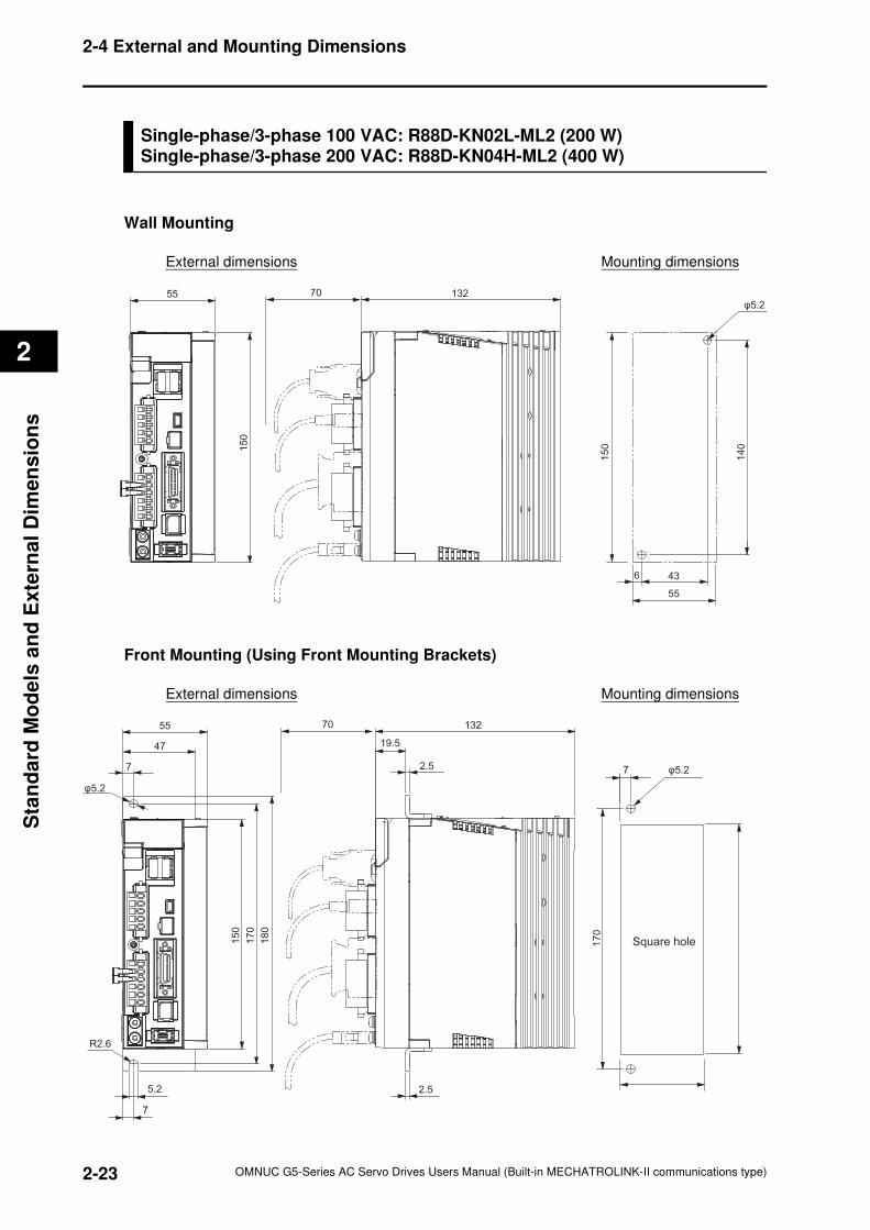
2-23
2-4 External and Mounting Dimensions
OMNUC G5-Series AC Servo Drives Users Manual (Built-in MECHATROLINK-II communications type)
2
Sta
nd
ard
Mo
de
ls a
nd
Exte
rnal
Dim
en
sio
ns
Single-phase/3-phase 100 VAC: R88D-KN02L-ML2 (200 W)Single-phase/3-phase 200 VAC: R88D-KN04H-ML2 (400 W)
Wall Mounting
External dimensions Mounting dimensions
Front Mounting (Using Front Mounting Brackets)
External dimensions Mounting dimensions
55
15
0
132
150
436
55
140
70
φ5.2
55
47
7
φ5.2
180
170
150
7
5.2
R2.6
2.5
132
19.5
2.5 7
170
70
φ5.2
Square hole
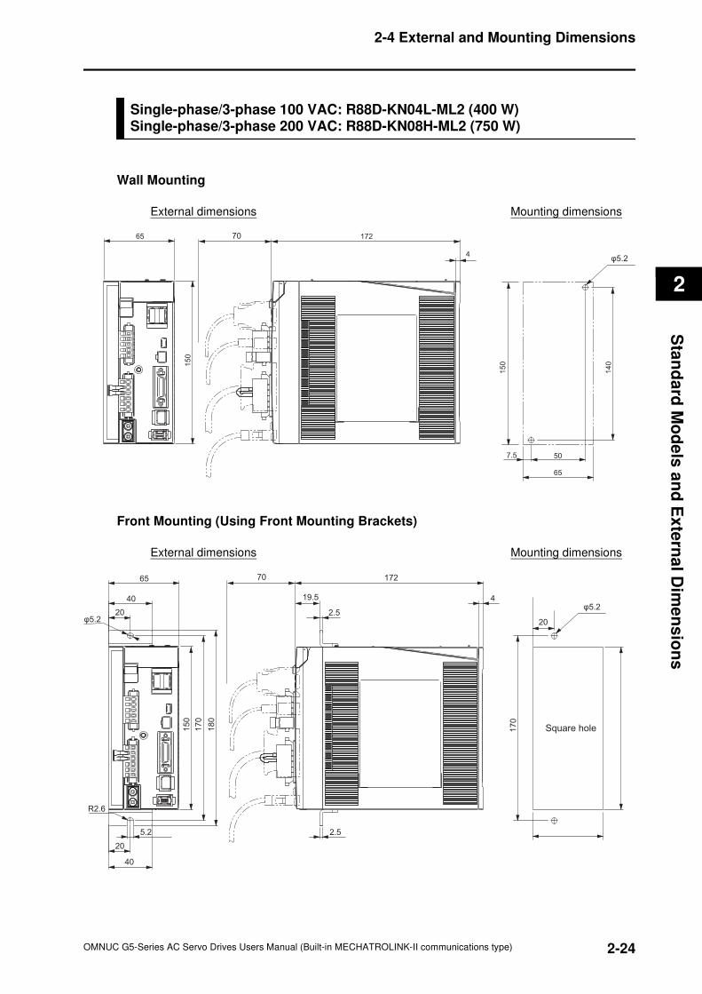
2-24
2-4 External and Mounting Dimensions
OMNUC G5-Series AC Servo Drives Users Manual (Built-in MECHATROLINK-II communications type)
2
Sta
nd
ard
Mo
de
ls a
nd
Ex
tern
al D
ime
ns
ion
s
Single-phase/3-phase 100 VAC: R88D-KN04L-ML2 (400 W) Single-phase/3-phase 200 VAC: R88D-KN08H-ML2 (750 W)
Wall Mounting
External dimensions Mounting dimensions
Front Mounting (Using Front Mounting Brackets)
External dimensions Mounting dimensions
172
4
65
150
150
140
507.5
65
70
φ5.2
65
40
20φ5.2
R2.6
20
40
5.2
180
170
150
172
4
2.5
19.5
2.5
170
20
70
φ5.2
Square hole
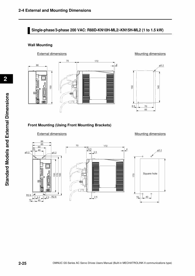
2-25
2-4 External and Mounting Dimensions
OMNUC G5-Series AC Servo Drives Users Manual (Built-in MECHATROLINK-II communications type)
2
Sta
nd
ard
Mo
de
ls a
nd
Exte
rnal
Dim
en
sio
ns
Single-phase/3-phase 200 VAC: R88D-KN10H-ML2/-KN15H-ML2 (1 to 1.5 kW)
Wall Mounting
External dimensions Mounting dimensions
Front Mounting (Using Front Mounting Brackets)
External dimensions Mounting dimensions
86
15
0
172
4 φ5.2
140
150
708.5
85
70
170
4010R2.6
R2.6
φ5.2 φ5.2
170
180
150
86
8560
4010
5.25.2
4010
19.5
2.5
172
4
70
φ5.2
Square hole
2.5
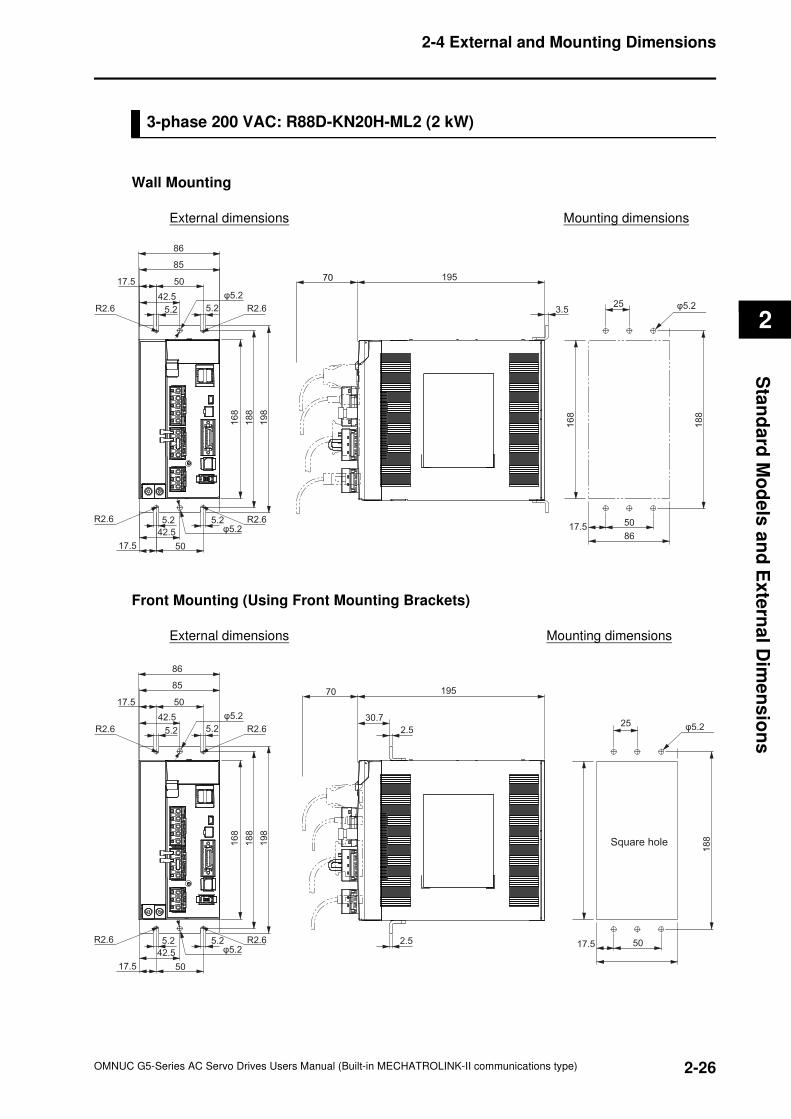
2-26
2-4 External and Mounting Dimensions
OMNUC G5-Series AC Servo Drives Users Manual (Built-in MECHATROLINK-II communications type)
2
Sta
nd
ard
Mo
de
ls a
nd
Ex
tern
al D
ime
ns
ion
s
3-phase 200 VAC: R88D-KN20H-ML2 (2 kW)
Wall Mounting
External dimensions Mounting dimensions
Front Mounting (Using Front Mounting Brackets)
External dimensions Mounting dimensions
86
85
5017.5
42.5
5.2 5.2
φ5.2
R2.6 R2.6
198
188
168
17.5 50
5.25.2
42.5 φ5.2R2.6 R2.6
195
3.5
70
25
188
168
86
5017.5
φ5.2
86
85
5017.5
42.5
5.2 5.2
198
188
168
17.5 50
5.25.2
42.5 φ5.2
φ5.2
R2.6
R2.6
R2.6
R2.6
195
30.7
2.5
2.5
70
25
188
5017.5
φ5.2
Square hole
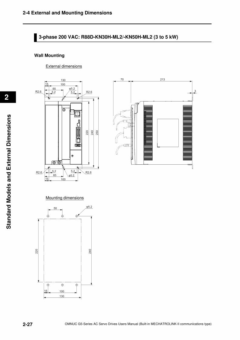
2-27
2-4 External and Mounting Dimensions
OMNUC G5-Series AC Servo Drives Users Manual (Built-in MECHATROLINK-II communications type)
2
Sta
nd
ard
Mo
de
ls a
nd
Exte
rnal
Dim
en
sio
ns
3-phase 200 VAC: R88D-KN30H-ML2/-KN50H-ML2 (3 to 5 kW)
Wall Mounting
External dimensions
Mounting dimensions
R2.6R2.6φ5.2
R2.6R2.6φ5.2
130
10015
65
5.2 5.2
220
240
250
5.2 5.2
65
10015
21370
3
φ5.250
240
100
130
15
220
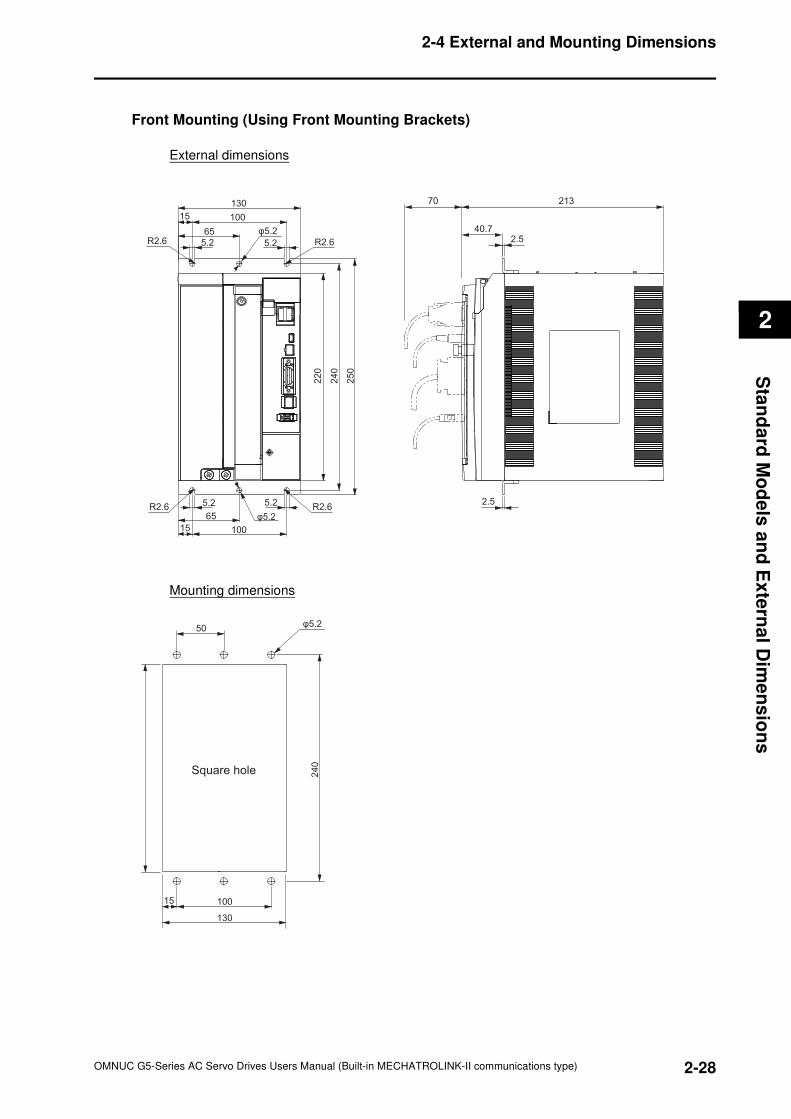
2-28
2-4 External and Mounting Dimensions
OMNUC G5-Series AC Servo Drives Users Manual (Built-in MECHATROLINK-II communications type)
2
Sta
nd
ard
Mo
de
ls a
nd
Ex
tern
al D
ime
ns
ion
s
Front Mounting (Using Front Mounting Brackets)
External dimensions
Mounting dimensions
R2.6R2.6φ5.2
R2.6R2.6φ5.2
130
10015
65
5.2 5.2
220
240
250
5.2 5.2
65
10015
213
40.72.5
2.5
70
φ5.250
240
100
130
15
Square hole
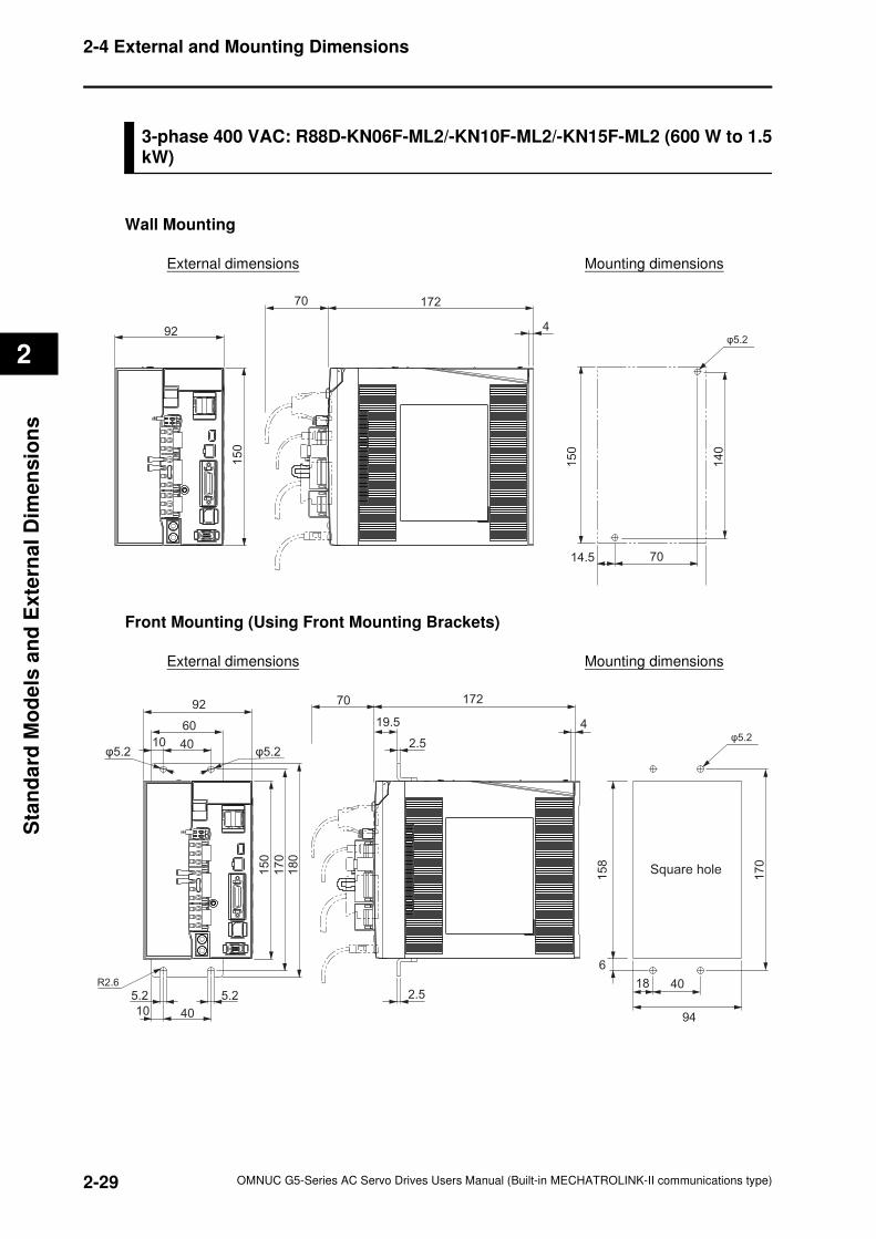
2-29
2-4 External and Mounting Dimensions
OMNUC G5-Series AC Servo Drives Users Manual (Built-in MECHATROLINK-II communications type)
2
Sta
nd
ard
Mo
de
ls a
nd
Exte
rnal
Dim
en
sio
ns
3-phase 400 VAC: R88D-KN06F-ML2/-KN10F-ML2/-KN15F-ML2 (600 W to 1.5kW)
Wall Mounting
External dimensions Mounting dimensions
Front Mounting (Using Front Mounting Brackets)
External dimensions Mounting dimensions
92
150
172
4
150
140
7014.5
70
φ5.2
92
60
4010φ5.2 φ5.2
170
180
150
5.2 5.2
10 40
R2.6
17270
4
2.5
19.5
2.54018
6
94
170
158
φ5.2
Square hole
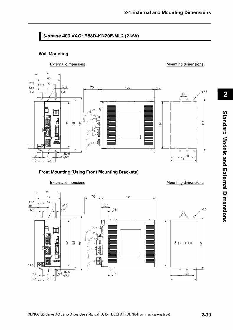
2-30
2-4 External and Mounting Dimensions
OMNUC G5-Series AC Servo Drives Users Manual (Built-in MECHATROLINK-II communications type)
2
Sta
nd
ard
Mo
de
ls a
nd
Ex
tern
al D
ime
ns
ion
s
3-phase 400 VAC: R88D-KN20F-ML2 (2 kW)
Wall Mounting
External dimensions Mounting dimensions
Front Mounting (Using Front Mounting Brackets)
External dimensions Mounting dimensions
φ5.2
R2.6
R2.6
φ5.2
25
180
50
94168
195 1.5
94
85
5017.5
42.5
5.2 5.2
5.2 5.2
5017.5
168
188
198
70φ5.2
φ5.2
R2.6
R2.6
φ5.2
25
188
502.5
195
30.7
94
85
50
5.2
17.5
42.5
168
188
198
5.2
17.5 50
5.2
2.55.2
70
φ5.2
Square hole
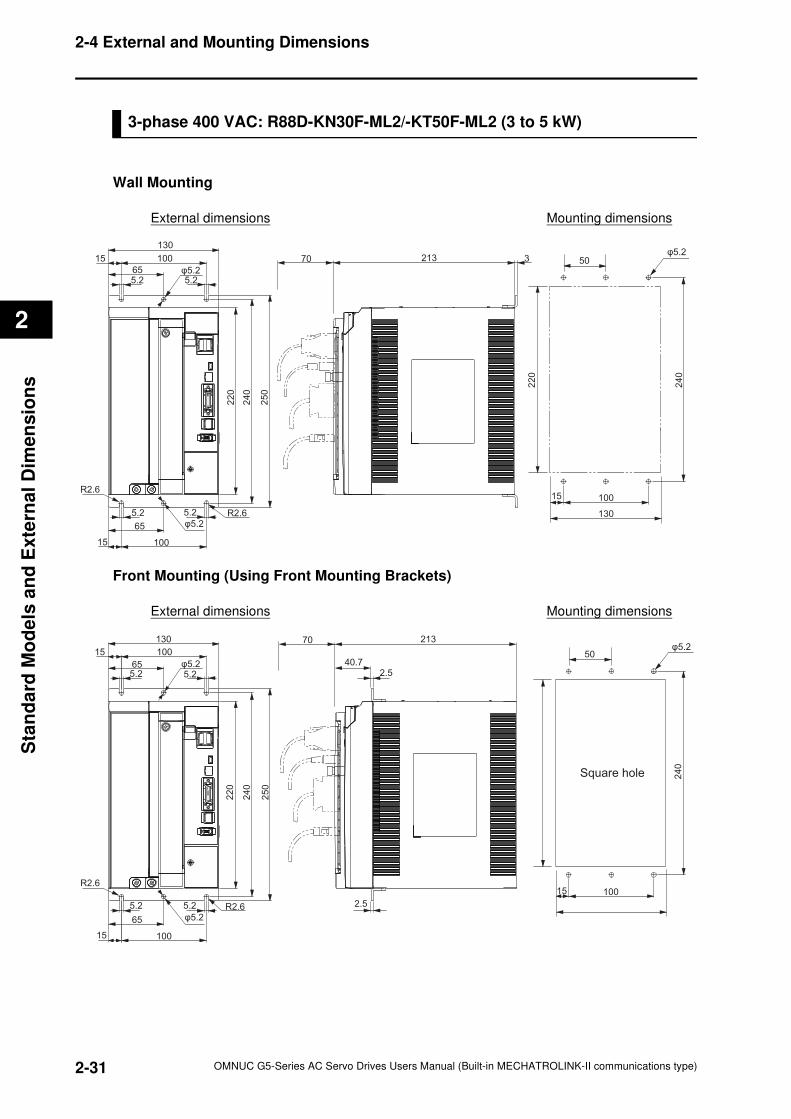
2-31
2-4 External and Mounting Dimensions
OMNUC G5-Series AC Servo Drives Users Manual (Built-in MECHATROLINK-II communications type)
2
Sta
nd
ard
Mo
de
ls a
nd
Exte
rnal
Dim
en
sio
ns
3-phase 400 VAC: R88D-KN30F-ML2/-KT50F-ML2 (3 to 5 kW)
Wall Mounting
External dimensions Mounting dimensions
Front Mounting (Using Front Mounting Brackets)
External dimensions Mounting dimensions
φ5.2
R2.6φ5.2
R2.6
100
5.25.2
65
15
15
130
100
655.2 5.2
220
240
250
50
240
220
130
10015
213 370φ5.2
φ5.25.2
R2.6φ5.2
R2.6
250
240
220
10015
5.2 5.2
65
5.265
130
1001540.7
2.5
213
2.5
50
240
10015
70φ5.2
Square hole
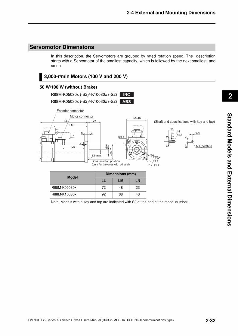
2-32
2-4 External and Mounting Dimensions
OMNUC G5-Series AC Servo Drives Users Manual (Built-in MECHATROLINK-II communications type)
2
Sta
nd
ard
Mo
de
ls a
nd
Ex
tern
al D
ime
ns
ion
s
Servomotor Dimensions
In this description, the Servomotors are grouped by rated rotation speed. The description
starts with a Servomotor of the smallest capacity, which is followed by the next smallest, and
so on.
3,000-r/min Motors (100 V and 200 V)
50 W/100 W (without Brake)
R88M-K05030x (-S2)/-K10030x (-S2)
R88M-K05030x (-S2)/-K10030x (-S2)
Note. Models with a key and tap are indicated with S2 at the end of the model number.
INC
ABS
M3 (depth 6)
φ8h
6
φ30
h7
2514
12.53h9
36
.2
25LL
LM
6 3
1.5 min.
Boss insertion position
(only for the ones with oil seal)
2
LN
R3.7
R4.2
2−φ4.3
φ46±0.2
40×40
(Shaft end specifications with key and tap)
Encoder connector
Motor connector
ModelDimensions (mm)
LL LM LN
R88M-K05030x 72 48 23
R88M-K10030x 92 68 43
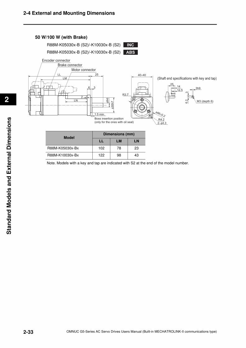
2-33
2-4 External and Mounting Dimensions
OMNUC G5-Series AC Servo Drives Users Manual (Built-in MECHATROLINK-II communications type)
2
Sta
nd
ard
Mo
de
ls a
nd
Exte
rnal
Dim
en
sio
ns
50 W/100 W (with Brake)
R88M-K05030x-B (S2)/-K10030x-B (S2)
R88M-K05030x-B (S2)/-K10030x-B (S2)
Note. Models with a key and tap are indicated with S2 at the end of the model number.
INC
ABS
M3 (depth 6)
2514
12.53h9
36
.2
R3.7
R4.2
2−φ4.3
φ46±0.2
40×40LL
LM
Motor connector
φ8h
6
φ3
0h
7
25
36
2
1.5 min.
Boss insertion position
(only for the ones with oil seal)
LN
(Shaft end specifications with key and tap)
Brake connector
Encoder connector
ModelDimensions (mm)
LL LM LN
R88M-K05030x-Bx 102 78 23
R88M-K10030x-Bx 122 98 43
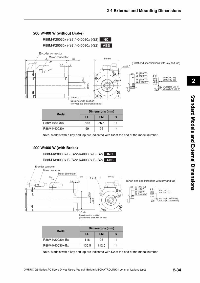
2-34
2-4 External and Mounting Dimensions
OMNUC G5-Series AC Servo Drives Users Manual (Built-in MECHATROLINK-II communications type)
2
Sta
nd
ard
Mo
de
ls a
nd
Ex
tern
al D
ime
ns
ion
s
200 W/400 W (without Brake)
R88M-K20030x (-S2)/-K40030x (-S2)
R88M-K20030x (-S2)/-K40030x (-S2)
Note. Models with a key and tap are indicated with S2 at the end of the model number..
200 W/400 W (with Brake)
R88M-K20030x-B (S2)/-K40030x-B (S2)
R88M-K20030x-B (S2)/-K40030x-B (S2)
Note. Models with a key and tap are indicated with S2 at the end of the model number.
INC
ABS
φS
h6
φ5
0h
7
30 20 (200 W)25 (400 W)
22.5 (400 W)
5 (
40
0 W
)4
(20
0 W
)8
.511
LL
LM30
36.5
φ70±0.2
60×60
(Shaft end specifications with key and tap)
1.5 min.
Boss insertion position
(only for the ones with oil seal)
4h9 (200 W)5h9 (400 W)
M4, depth 8 (200 W) M5, depth 10 (400 W)
18 (200 W)
4−φ4.5
Motor connector
Encoder connector
ModelDimensions (mm)
LL LM S
R88M-K20030x 79.5 56.5 11
R88M-K40030x 99 76 14
INC
ABS
30 20 (200 W)25 (400 W)
22.5 (400 W)
5 (
40
0 W
)4
(20
0 W
)8
.511
φ70±0.2
60×60
(Shaft end specifications with key and tap)
1.5 min.
Boss insertion position
(only for the ones with oil seal)
6.5 3
LLLM
30
4h9 (200 W)5h9 (400 W)
M4, depth 8 (200 W) M5, depth 10 (400 W)
18 (200 W)
φS
h6
φ5
0h
7
4−ø4.5
Brake connector
Encoder connector
Motor connector
ModelDimensions (mm)
LL LM S
R88M-K20030x-Bx 116 93 11
R88M-K40030x-Bx 135.5 112.5 14
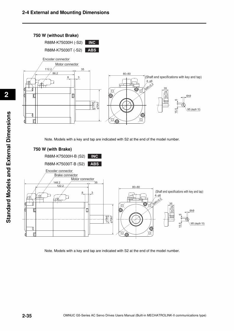
2-35
2-4 External and Mounting Dimensions
OMNUC G5-Series AC Servo Drives Users Manual (Built-in MECHATROLINK-II communications type)
2
Sta
nd
ard
Mo
de
ls a
nd
Exte
rnal
Dim
en
sio
ns
750 W (without Brake)
R88M-K75030H (-S2)
R88M-K75030T (-S2)
Note. Models with a key and tap are indicated with S2 at the end of the model number.
750 W (with Brake)
R88M-K75030H-B (S2)
R88M-K75030T-B (S2)
Note. Models with a key and tap are indicated with S2 at the end of the model number.
INC
ABS
(Shaft end specifications with key and tap)
35
25
22 6h9
15
.56
112.2 35
86.2
8 3
φ1
9h
6
φ70
h7
Motor connector
Encoder connector
80×80
4−φ6
φ90±
0.2
M5 (depth 10)
INC
ABS
Motor connectorBrake connector
Encoder connector
(Shaft end specifications with key and tap)
148.2 35
122.2
35
25
22
8 3
φ19
h6
φ70
h7
4−φ6
80×80
φ90±
0.2
M5 (depth 10)
6h9
15
.56
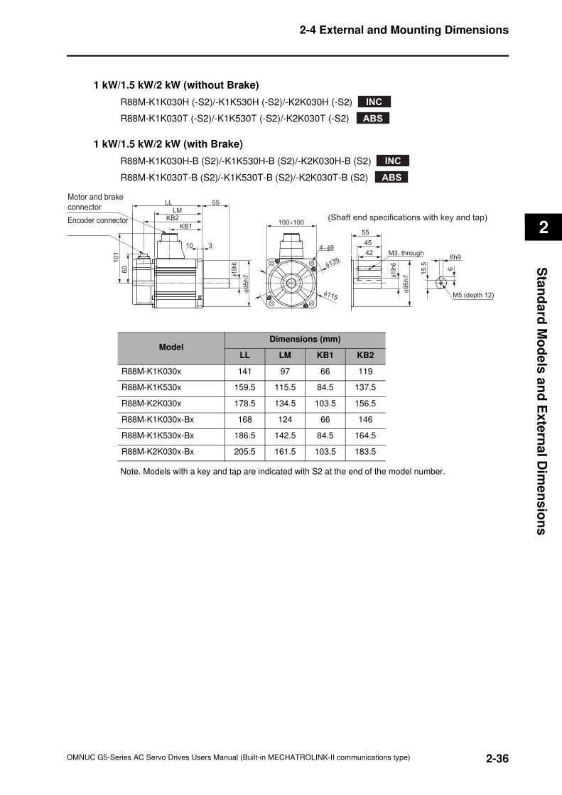
2-36
2-4 External and Mounting Dimensions
OMNUC G5-Series AC Servo Drives Users Manual (Built-in MECHATROLINK-II communications type)
2
Sta
nd
ard
Mo
de
ls a
nd
Ex
tern
al D
ime
ns
ion
s
1 kW/1.5 kW/2 kW (without Brake)
R88M-K1K030H (-S2)/-K1K530H (-S2)/-K2K030H (-S2)
R88M-K1K030T (-S2)/-K1K530T (-S2)/-K2K030T (-S2)
1 kW/1.5 kW/2 kW (with Brake)
R88M-K1K030H-B (S2)/-K1K530H-B (S2)/-K2K030H-B (S2)
R88M-K1K030T-B (S2)/-K1K530T-B (S2)/-K2K030T-B (S2)
Note. Models with a key and tap are indicated with S2 at the end of the model number.
ModelDimensions (mm)
LL LM KB1 KB2
R88M-K1K030x 141 97 66 119
R88M-K1K530x 159.5 115.5 84.5 137.5
R88M-K2K030x 178.5 134.5 103.5 156.5
R88M-K1K030x-Bx 168 124 66 146
R88M-K1K530x-Bx 186.5 142.5 84.5 164.5
R88M-K2K030x-Bx 205.5 161.5 103.5 183.5
INC
ABS
INC
ABS
LMKB2
KB1
55LL
3
101
60
10
φ19
h6
φ95
h7
φ115
4−φ942
45
55
φ135
100×100Encoder connector
Motor and brake
connector
M3, through6h9
φ19
h6 6
15
.5
φ9
5h
7
M5 (depth 12)
(Shaft end specifications with key and tap)
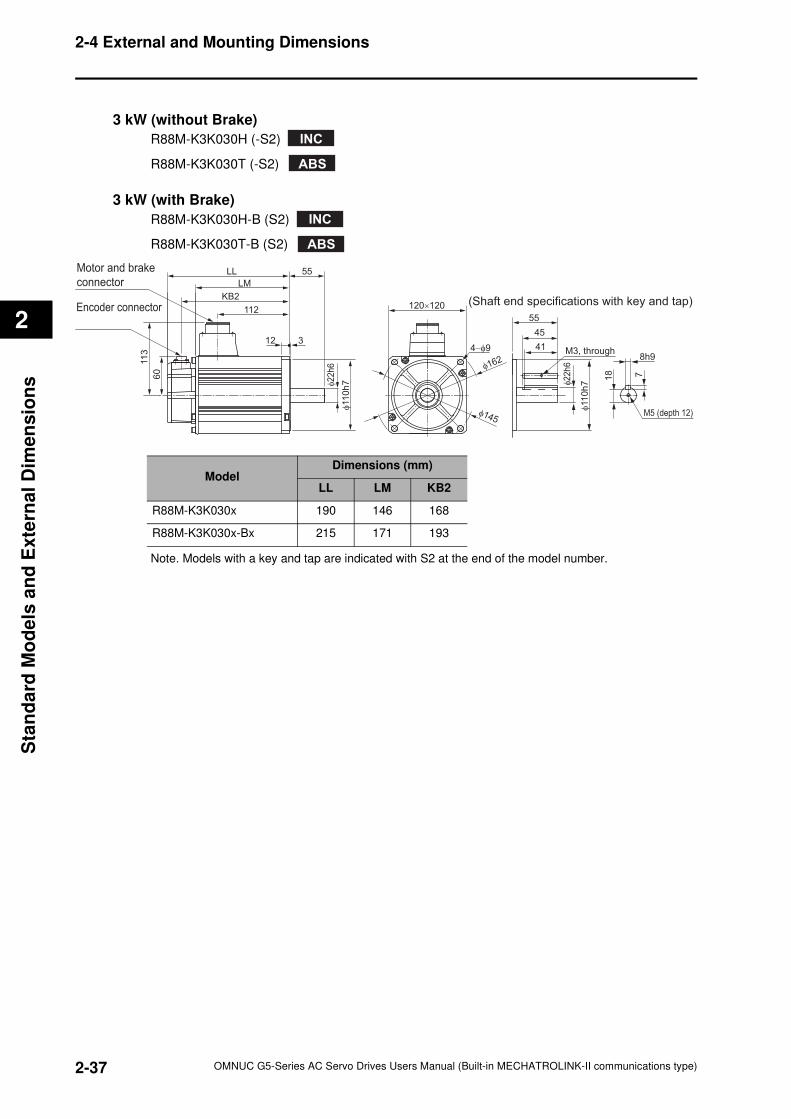
2-37
2-4 External and Mounting Dimensions
OMNUC G5-Series AC Servo Drives Users Manual (Built-in MECHATROLINK-II communications type)
2
Sta
nd
ard
Mo
de
ls a
nd
Exte
rnal
Dim
en
sio
ns
3 kW (without Brake)
R88M-K3K030H (-S2)
R88M-K3K030T (-S2)
3 kW (with Brake)
R88M-K3K030H-B (S2)
R88M-K3K030T-B (S2)
Note. Models with a key and tap are indicated with S2 at the end of the model number.
INC
ABS
INC
ABS
Encoder connector
Motor and brake
connector LM
KB2
112
55LL
113
60
312φ22
h6
φ11
0h
7
120×120
4−φ9
φ145
φ162
41
45
55
M3, through
M5 (depth 12)
φ22
h6
φ11
0h
7
8h9
718
(Shaft end specifications with key and tap)
ModelDimensions (mm)
LL LM KB2
R88M-K3K030x 190 146 168
R88M-K3K030x-Bx 215 171 193
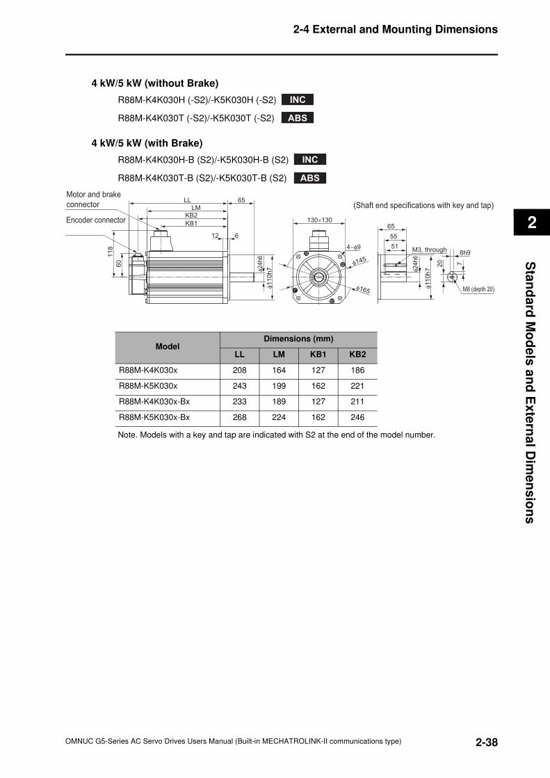
2-38
2-4 External and Mounting Dimensions
OMNUC G5-Series AC Servo Drives Users Manual (Built-in MECHATROLINK-II communications type)
2
Sta
nd
ard
Mo
de
ls a
nd
Ex
tern
al D
ime
ns
ion
s
4 kW/5 kW (without Brake)
R88M-K4K030H (-S2)/-K5K030H (-S2)
R88M-K4K030T (-S2)/-K5K030T (-S2)
4 kW/5 kW (with Brake)
R88M-K4K030H-B (S2)/-K5K030H-B (S2)
R88M-K4K030T-B (S2)/-K5K030T-B (S2)
Note. Models with a key and tap are indicated with S2 at the end of the model number.
INC
ABS
INC
ABS
Encoder connector
Motor and brake
connector LMKB2
KB1
65LL
11
8
60
612
φ24
h6
φ1
10
h7
130×130
4−φ9
φ165
φ145
51
55
65
M3, through
M8 (depth 20)
φ24
h6
φ11
0h
7
8h9
720
(Shaft end specifications with key and tap)
ModelDimensions (mm)
LL LM KB1 KB2
R88M-K4K030x 208 164 127 186
R88M-K5K030x 243 199 162 221
R88M-K4K030x-Bx 233 189 127 211
R88M-K5K030x-Bx 268 224 162 246
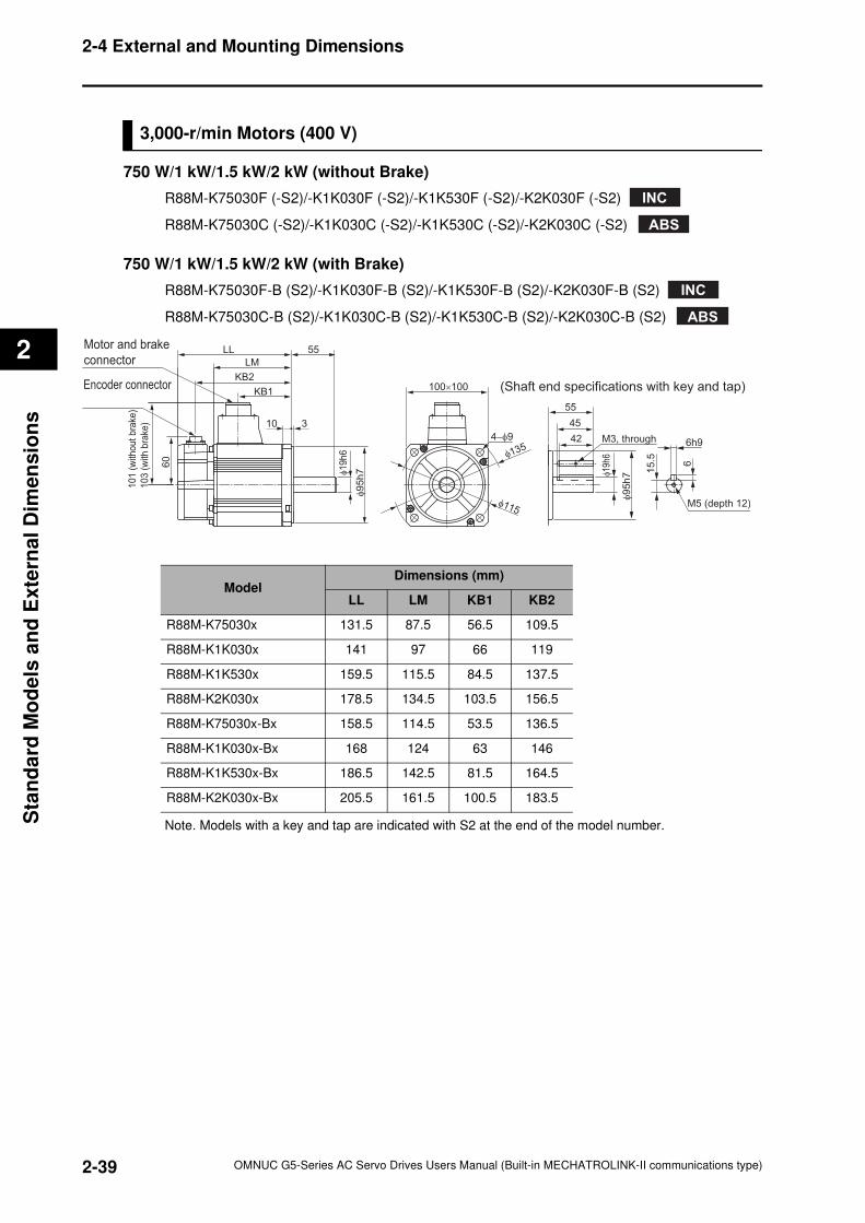
2-39
2-4 External and Mounting Dimensions
OMNUC G5-Series AC Servo Drives Users Manual (Built-in MECHATROLINK-II communications type)
2
Sta
nd
ard
Mo
de
ls a
nd
Exte
rnal
Dim
en
sio
ns
3,000-r/min Motors (400 V)
750 W/1 kW/1.5 kW/2 kW (without Brake)
R88M-K75030F (-S2)/-K1K030F (-S2)/-K1K530F (-S2)/-K2K030F (-S2)
R88M-K75030C (-S2)/-K1K030C (-S2)/-K1K530C (-S2)/-K2K030C (-S2)
750 W/1 kW/1.5 kW/2 kW (with Brake)
R88M-K75030F-B (S2)/-K1K030F-B (S2)/-K1K530F-B (S2)/-K2K030F-B (S2)
R88M-K75030C-B (S2)/-K1K030C-B (S2)/-K1K530C-B (S2)/-K2K030C-B (S2)
Note. Models with a key and tap are indicated with S2 at the end of the model number.
INC
ABS
INC
ABS
Encoder connector
Motor and brake
connector LM
KB2
KB1
55LL
101
(w
ithout
bra
ke)
103
(w
ith b
rake
)
60
310
φ19
h6
φ95
h7
100×100
4−φ9
φ115
φ13542
45
55
M3, through
M5 (depth 12)
φ19
h6
φ9
5h
7
6h9
6
15
.5
(Shaft end specifications with key and tap)
ModelDimensions (mm)
LL LM KB1 KB2
R88M-K75030x 131.5 87.5 56.5 109.5
R88M-K1K030x 141 97 66 119
R88M-K1K530x 159.5 115.5 84.5 137.5
R88M-K2K030x 178.5 134.5 103.5 156.5
R88M-K75030x-Bx 158.5 114.5 53.5 136.5
R88M-K1K030x-Bx 168 124 63 146
R88M-K1K530x-Bx 186.5 142.5 81.5 164.5
R88M-K2K030x-Bx 205.5 161.5 100.5 183.5
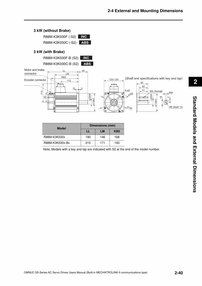
2-40
2-4 External and Mounting Dimensions
OMNUC G5-Series AC Servo Drives Users Manual (Built-in MECHATROLINK-II communications type)
2
Sta
nd
ard
Mo
de
ls a
nd
Ex
tern
al D
ime
ns
ion
s
3 kW (without Brake)
R88M-K3K030F (-S2)
R88M-K3K030C (-S2)
3 kW (with Brake)
R88M-K3K030F-B (S2)
R88M-K3K030C-B (S2)
Note. Models with a key and tap are indicated with S2 at the end of the model number.
INC
ABS
INC
ABS
Encoder connector
Motor and brake
connector LM
KB2
112
55LL
113
60
312φ2
2h
6
φ1
10
h7
120×120
4-φ9
φ145
φ162
41
45
55
M3, through
M5 (depth 12)
φ22
h6
φ110
h7
8h9
718
(Shaft end specifications with key and tap)
ModelDimensions (mm)
LL LM KB2
R88M-K3K030x 190 146 168
R88M-K3K030x-Bx 215 171 193
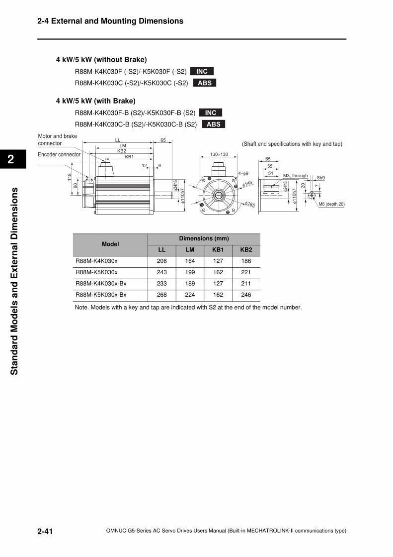
2-41
2-4 External and Mounting Dimensions
OMNUC G5-Series AC Servo Drives Users Manual (Built-in MECHATROLINK-II communications type)
2
Sta
nd
ard
Mo
de
ls a
nd
Exte
rnal
Dim
en
sio
ns
4 kW/5 kW (without Brake)
R88M-K4K030F (-S2)/-K5K030F (-S2)
R88M-K4K030C (-S2)/-K5K030C (-S2)
4 kW/5 kW (with Brake)
R88M-K4K030F-B (S2)/-K5K030F-B (S2)
R88M-K4K030C-B (S2)/-K5K030C-B (S2)
Note. Models with a key and tap are indicated with S2 at the end of the model number.
INC
ABS
INC
ABS
Encoder connector
Motor and brake
connector LMKB2
KB1
65LL
118
60
612
φ2
4h
6
φ1
10
h7
130×130
4−φ9
φ165
φ145
51
55
65
M3, through
M8 (depth 20)
φ24
h6
φ110
h7
8h9
720
(Shaft end specifications with key and tap)
ModelDimensions (mm)
LL LM KB1 KB2
R88M-K4K030x 208 164 127 186
R88M-K5K030x 243 199 162 221
R88M-K4K030x-Bx 233 189 127 211
R88M-K5K030x-Bx 268 224 162 246
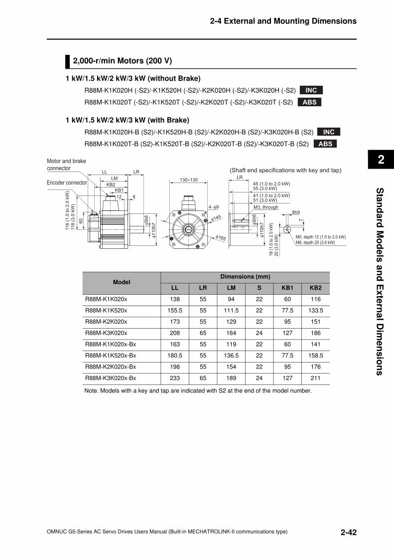
2-42
2-4 External and Mounting Dimensions
OMNUC G5-Series AC Servo Drives Users Manual (Built-in MECHATROLINK-II communications type)
2
Sta
nd
ard
Mo
de
ls a
nd
Ex
tern
al D
ime
ns
ion
s
2,000-r/min Motors (200 V)
1 kW/1.5 kW/2 kW/3 kW (without Brake)
R88M-K1K020H (-S2)/-K1K520H (-S2)/-K2K020H (-S2)/-K3K020H (-S2)
R88M-K1K020T (-S2)/-K1K520T (-S2)/-K2K020T (-S2)/-K3K020T (-S2)
1 kW/1.5 kW/2 kW/3 kW (with Brake)
R88M-K1K020H-B (S2)/-K1K520H-B (S2)/-K2K020H-B (S2)/-K3K020H-B (S2)
R88M-K1K020T-B (S2)-K1K520T-B (S2)/-K2K020T-B (S2)/-K3K020T-B (S2)
Note. Models with a key and tap are indicated with S2 at the end of the model number.
ModelDimensions (mm)
LL LR LM S KB1 KB2
R88M-K1K020x 138 55 94 22 60 116
R88M-K1K520x 155.5 55 111.5 22 77.5 133.5
R88M-K2K020x 173 55 129 22 95 151
R88M-K3K020x 208 65 164 24 127 186
R88M-K1K020x-Bx 163 55 119 22 60 141
R88M-K1K520x-Bx 180.5 55 136.5 22 77.5 158.5
R88M-K2K020x-Bx 198 55 154 22 95 176
R88M-K3K020x-Bx 233 65 189 24 127 211
INC
ABS
INC
ABS
Encoder connector
Motor and brake
connector
LM
KB2
KB1
LRLL
11
6 (
1.0
to 2
.0 k
W)
11
8 (
3.0
kW
)
60
130×13045 (1.0 to 2.0 kW)55 (3.0 kW)
41 (1.0 to 2.0 kW)51 (3.0 kW)
LR
M3, through
M5, depth 12 (1.0 to 2.0 kW)
M8, depth 20 (3.0 kW)
8h9
7
18
(1.0
to
2.0
kW
)20
(3.0
kW
)
(Shaft end specifications with key and tap)
612
φS
h6
φS
h6
φ1
10
h7
4−φ9
φ165
φ145
φ11
0h
7
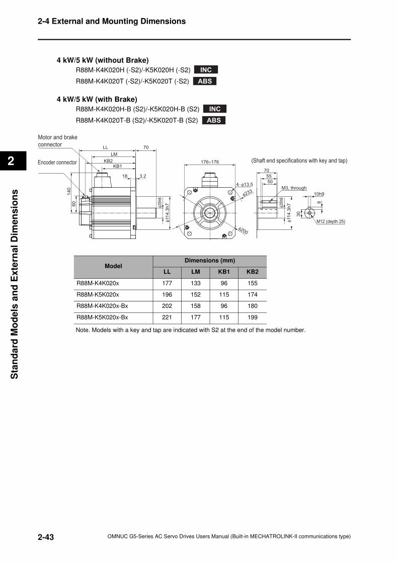
2-43
2-4 External and Mounting Dimensions
OMNUC G5-Series AC Servo Drives Users Manual (Built-in MECHATROLINK-II communications type)
2
Sta
nd
ard
Mo
de
ls a
nd
Exte
rnal
Dim
en
sio
ns
4 kW/5 kW (without Brake)
R88M-K4K020H (-S2)/-K5K020H (-S2)
R88M-K4K020T (-S2)/-K5K020T (-S2)
4 kW/5 kW (with Brake)
R88M-K4K020H-B (S2)/-K5K020H-B (S2)
R88M-K4K020T-B (S2)/-K5K020T-B (S2)
Note. Models with a key and tap are indicated with S2 at the end of the model number.
ModelDimensions (mm)
LL LM KB1 KB2
R88M-K4K020x 177 133 96 155
R88M-K5K020x 196 152 115 174
R88M-K4K020x-Bx 202 158 96 180
R88M-K5K020x-Bx 221 177 115 199
INC
ABS
INC
ABS
Encoder connector
Motor and brake
connector
LM
KB2KB1
70LL
140
60
176×176
70
55
50
M3, through
(Shaft end specifications with key and tap)
3.218
φ11
4.3
h7
4−φ13.5
φ200
φ233
φ35
h6
φ35
h6
φ11
4.3
h7
M12 (depth 25)
10h9
8
30
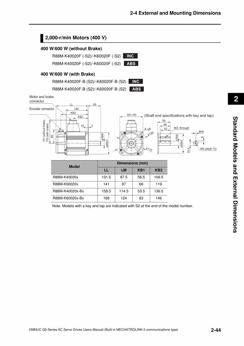
2-44
2-4 External and Mounting Dimensions
OMNUC G5-Series AC Servo Drives Users Manual (Built-in MECHATROLINK-II communications type)
2
Sta
nd
ard
Mo
de
ls a
nd
Ex
tern
al D
ime
ns
ion
s
2,000-r/min Motors (400 V)
400 W/600 W (without Brake)
R88M-K40020F (-S2)/-K60020F (-S2)
R88M-K40020F (-S2)/-K60020F (-S2)
400 W/600 W (with Brake)
R88M-K40020F-B (S2)/-K60020F-B (S2)
R88M-K40020F-B (S2)/-K60020F-B (S2)
Note. Models with a key and tap are indicated with S2 at the end of the model number.
ModelDimensions (mm)
LL LM KB1 KB2
R88M-K40020x 131.5 87.5 56.5 109.5
R88M-K60020x 141 97 66 119
R88M-K40020x-Bx 158.5 114.5 53.5 136.5
R88M-K60020x-Bx 168 124 63 146
INC
ABS
INC
ABS
100×100
4−φ9
Encoder connector
Motor and brake
connector
101
(w
ithout
bra
ke)
103
(w
ith b
rake
)
60
LM
KB2
KB1
55LL
310
φ95
h7
φ115
φ135
55
45
42 M3, through
φ9
5h
7φ19
h6
φ19
h6
M5 (depth 12)
6h9
6
15
.5
(Shaft end specifications with key and tap)
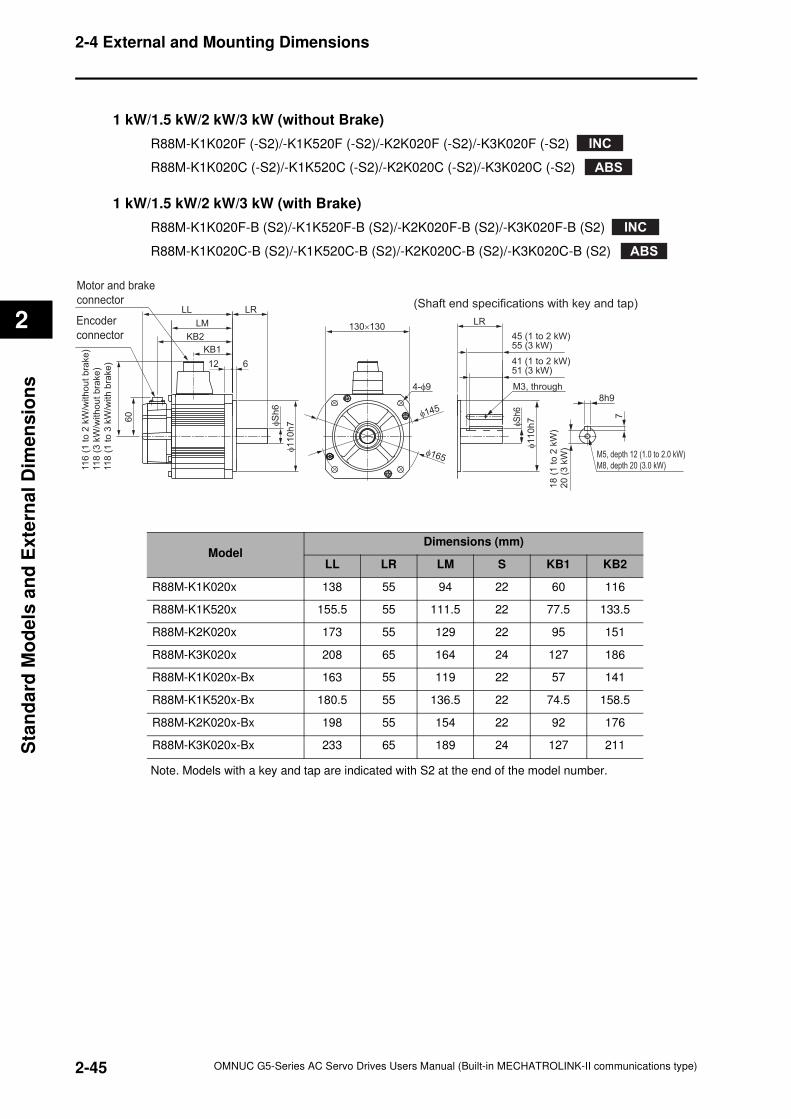
2-45
2-4 External and Mounting Dimensions
OMNUC G5-Series AC Servo Drives Users Manual (Built-in MECHATROLINK-II communications type)
2
Sta
nd
ard
Mo
de
ls a
nd
Exte
rnal
Dim
en
sio
ns
1 kW/1.5 kW/2 kW/3 kW (without Brake)
R88M-K1K020F (-S2)/-K1K520F (-S2)/-K2K020F (-S2)/-K3K020F (-S2)
R88M-K1K020C (-S2)/-K1K520C (-S2)/-K2K020C (-S2)/-K3K020C (-S2)
1 kW/1.5 kW/2 kW/3 kW (with Brake)
R88M-K1K020F-B (S2)/-K1K520F-B (S2)/-K2K020F-B (S2)/-K3K020F-B (S2)
R88M-K1K020C-B (S2)/-K1K520C-B (S2)/-K2K020C-B (S2)/-K3K020C-B (S2)
Note. Models with a key and tap are indicated with S2 at the end of the model number.
INC
ABS
INC
ABS
Encoder
connector
Motor and brake
connector
LM
KB2
KB1
LRLL
11
6 (
1 t
o 2
kW
/without
bra
ke
)
11
8 (
3 k
W/w
ithout
bra
ke
)
11
8 (
1 t
o 3
kW
/with b
rake
)
60
130×13045 (1 to 2 kW)55 (3 kW)
41 (1 to 2 kW)51 (3 kW)
LR
M3, through
M5, depth 12 (1.0 to 2.0 kW)
M8, depth 20 (3.0 kW)
8h9
7
18
(1
to 2
kW
)2
0 (
3 k
W)
(Shaft end specifications with key and tap)
612
φS
h6
φ1
10
h7
4-φ9
φ165
φ145
φS
h6
φ110
h7
ModelDimensions (mm)
LL LR LM S KB1 KB2
R88M-K1K020x 138 55 94 22 60 116
R88M-K1K520x 155.5 55 111.5 22 77.5 133.5
R88M-K2K020x 173 55 129 22 95 151
R88M-K3K020x 208 65 164 24 127 186
R88M-K1K020x-Bx 163 55 119 22 57 141
R88M-K1K520x-Bx 180.5 55 136.5 22 74.5 158.5
R88M-K2K020x-Bx 198 55 154 22 92 176
R88M-K3K020x-Bx 233 65 189 24 127 211
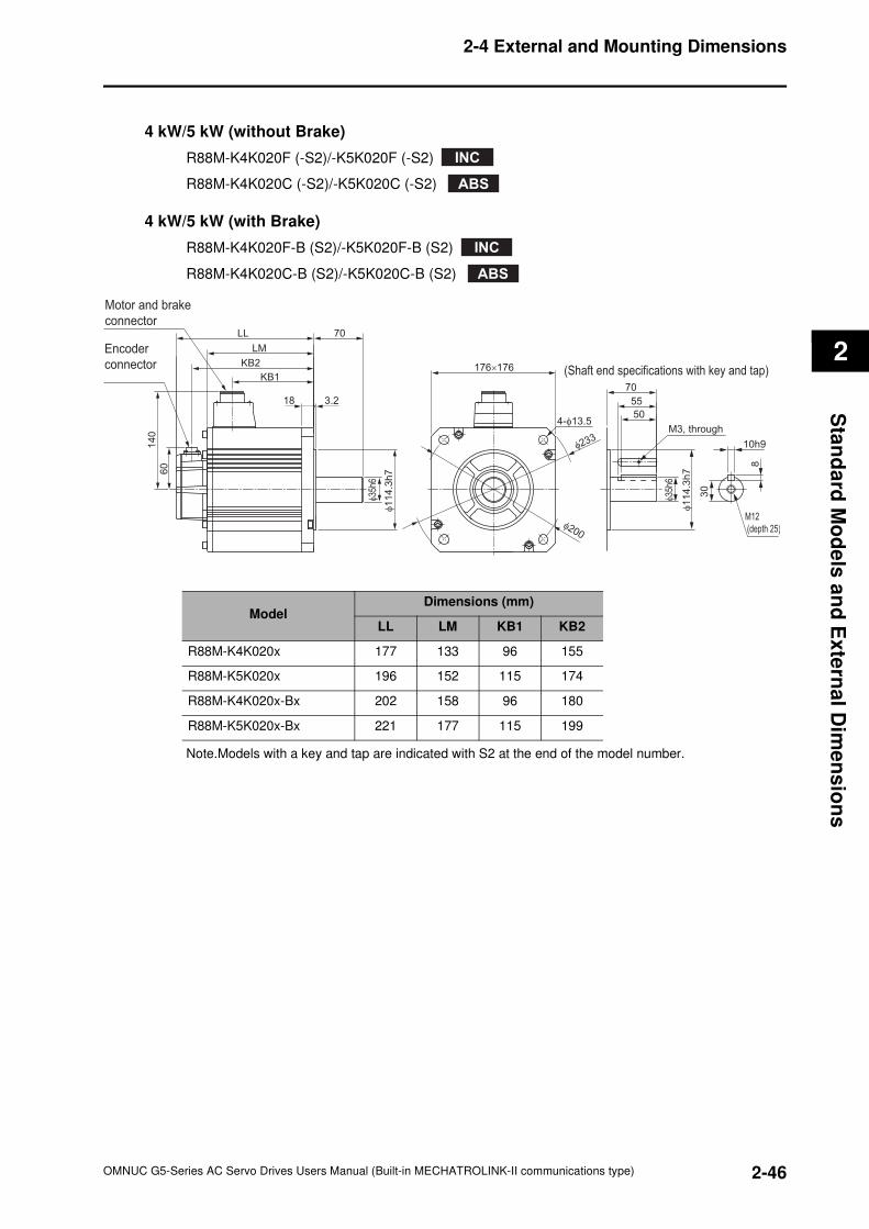
2-46
2-4 External and Mounting Dimensions
OMNUC G5-Series AC Servo Drives Users Manual (Built-in MECHATROLINK-II communications type)
2
Sta
nd
ard
Mo
de
ls a
nd
Ex
tern
al D
ime
ns
ion
s
4 kW/5 kW (without Brake)
R88M-K4K020F (-S2)/-K5K020F (-S2)
R88M-K4K020C (-S2)/-K5K020C (-S2)
4 kW/5 kW (with Brake)
R88M-K4K020F-B (S2)/-K5K020F-B (S2)
R88M-K4K020C-B (S2)/-K5K020C-B (S2)
Note.Models with a key and tap are indicated with S2 at the end of the model number.
ModelDimensions (mm)
LL LM KB1 KB2
R88M-K4K020x 177 133 96 155
R88M-K5K020x 196 152 115 174
R88M-K4K020x-Bx 202 158 96 180
R88M-K5K020x-Bx 221 177 115 199
INC
ABS
INC
ABS
Encoder
connector
Motor and brake
connector
LM
KB2
KB1
70LL
14
0
60
176×176
70
55
50
M3, through
(Shaft end specifications with key and tap)
3.218
φ35
h6
φ1
14
.3h
7
4-φ13.5
φ200
φ233
φ35
h6
φ1
14
.3h
7
M12
(depth 25)
10h9
8
30
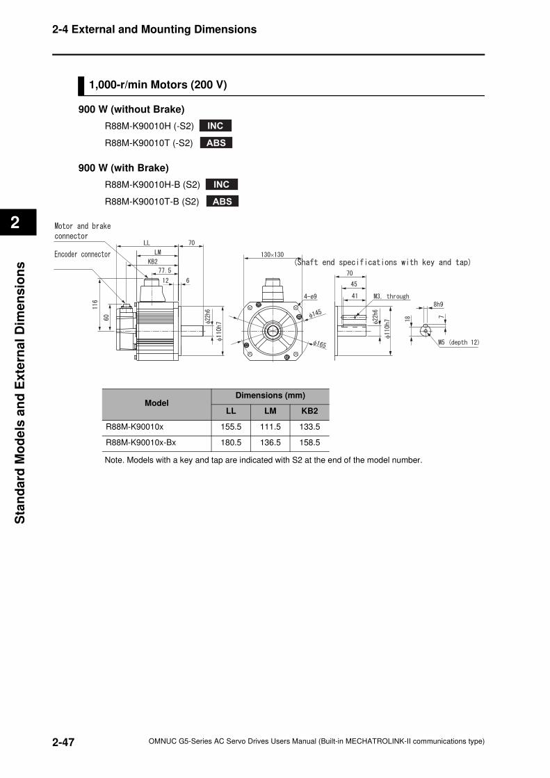
2-47
2-4 External and Mounting Dimensions
OMNUC G5-Series AC Servo Drives Users Manual (Built-in MECHATROLINK-II communications type)
2
Sta
nd
ard
Mo
de
ls a
nd
Exte
rnal
Dim
en
sio
ns
1,000-r/min Motors (200 V)
900 W (without Brake)
R88M-K90010H (-S2)
R88M-K90010T (-S2)
900 W (with Brake)
R88M-K90010H-B (S2)
R88M-K90010T-B (S2)
Note. Models with a key and tap are indicated with S2 at the end of the model number.
INC
ABS
INC
ABS
×
φ
φ
φ
φ
φ
φ
ModelDimensions (mm)
LL LM KB2
R88M-K90010x 155.5 111.5 133.5
R88M-K90010x-Bx 180.5 136.5 158.5
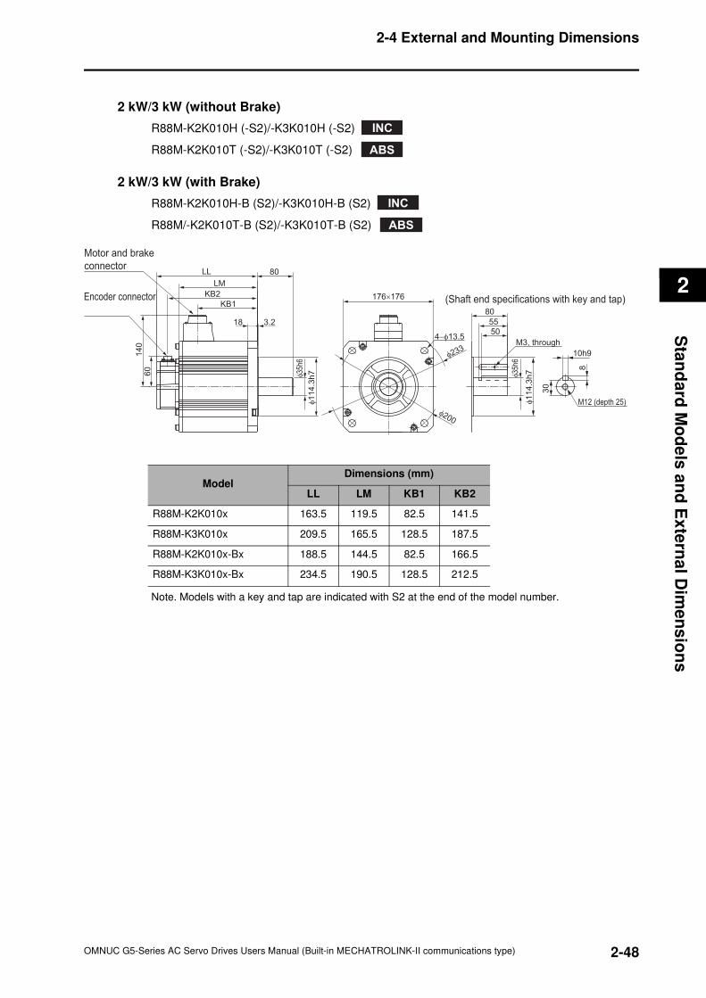
2-48
2-4 External and Mounting Dimensions
OMNUC G5-Series AC Servo Drives Users Manual (Built-in MECHATROLINK-II communications type)
2
Sta
nd
ard
Mo
de
ls a
nd
Ex
tern
al D
ime
ns
ion
s
2 kW/3 kW (without Brake)
R88M-K2K010H (-S2)/-K3K010H (-S2)
R88M-K2K010T (-S2)/-K3K010T (-S2)
2 kW/3 kW (with Brake)
R88M-K2K010H-B (S2)/-K3K010H-B (S2)
R88M/-K2K010T-B (S2)/-K3K010T-B (S2)
Note. Models with a key and tap are indicated with S2 at the end of the model number.
INC
ABS
INC
ABS
Encoder connector
Motor and brake
connector
LM
KB2
KB1
80LL
140
60
176×176
80
55
50
M3, through
(Shaft end specifications with key and tap)
3.218
φ35
h6
φ35
h6
φ114
.3h
7
4−φ13.5
φ200
φ233
φ1
14
.3h
7
M12 (depth 25)
10h9
8
30
ModelDimensions (mm)
LL LM KB1 KB2
R88M-K2K010x 163.5 119.5 82.5 141.5
R88M-K3K010x 209.5 165.5 128.5 187.5
R88M-K2K010x-Bx 188.5 144.5 82.5 166.5
R88M-K3K010x-Bx 234.5 190.5 128.5 212.5
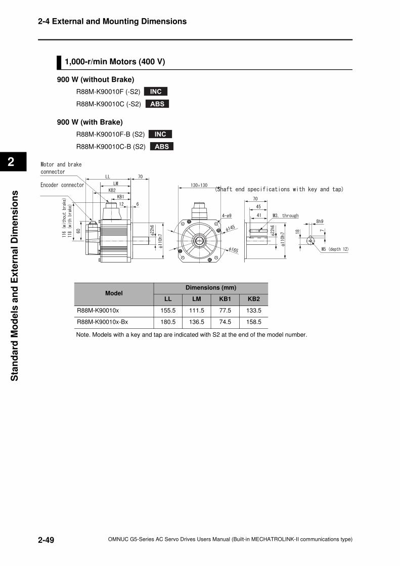
2-49
2-4 External and Mounting Dimensions
OMNUC G5-Series AC Servo Drives Users Manual (Built-in MECHATROLINK-II communications type)
2
Sta
nd
ard
Mo
de
ls a
nd
Exte
rnal
Dim
en
sio
ns
1,000-r/min Motors (400 V)
900 W (without Brake)
R88M-K90010F (-S2)
R88M-K90010C (-S2)
900 W (with Brake)
R88M-K90010F-B (S2)
R88M-K90010C-B (S2)
Note. Models with a key and tap are indicated with S2 at the end of the model number.
INC
ABS
INC
ABS
×
φ
φ
φ
φ
φ
φ
ModelDimensions (mm)
LL LM KB1 KB2
R88M-K90010x 155.5 111.5 77.5 133.5
R88M-K90010x-Bx 180.5 136.5 74.5 158.5
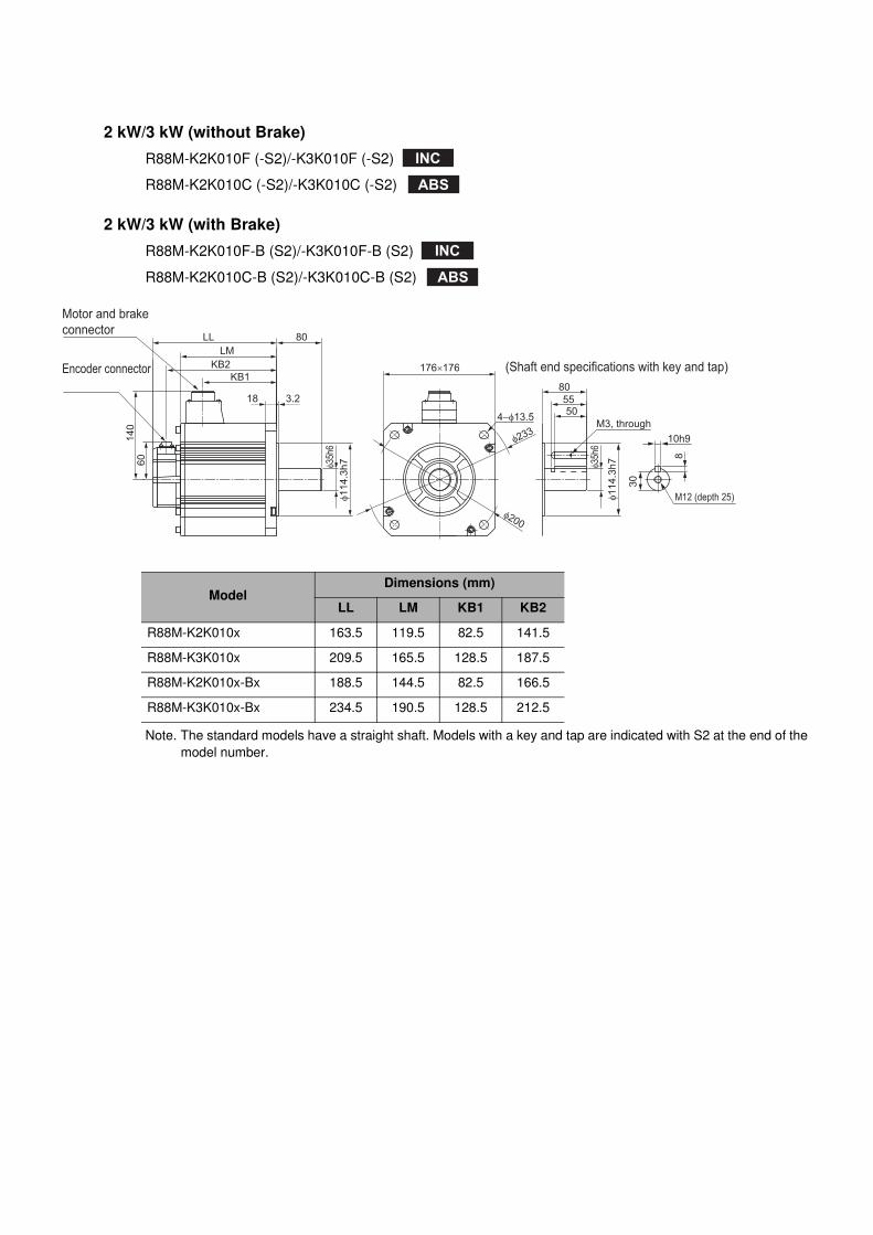
2 kW/3 kW (without Brake)
R88M-K2K010F (-S2)/-K3K010F (-S2)
R88M-K2K010C (-S2)/-K3K010C (-S2)
2 kW/3 kW (with Brake)
R88M-K2K010F-B (S2)/-K3K010F-B (S2)
R88M-K2K010C-B (S2)/-K3K010C-B (S2)
Note. The standard models have a straight shaft. Models with a key and tap are indicated with S2 at the end of the
model number.
ModelDimensions (mm)
LL LM KB1 KB2
R88M-K2K010x 163.5 119.5 82.5 141.5
R88M-K3K010x 209.5 165.5 128.5 187.5
R88M-K2K010x-Bx 188.5 144.5 82.5 166.5
R88M-K3K010x-Bx 234.5 190.5 128.5 212.5
INC
ABS
INC
ABS
Encoder connector
Motor and brake
connector
LM
KB2
KB1
80LL
140
60
176×176
80
5550
M3, through
(Shaft end specifications with key and tap)
3.218
φ35
h6
φ35
h6
φ114
.3h
7
4−φ13.5
φ200
φ233
φ1
14
.3h
7
M12 (depth 25)
10h9
8
30
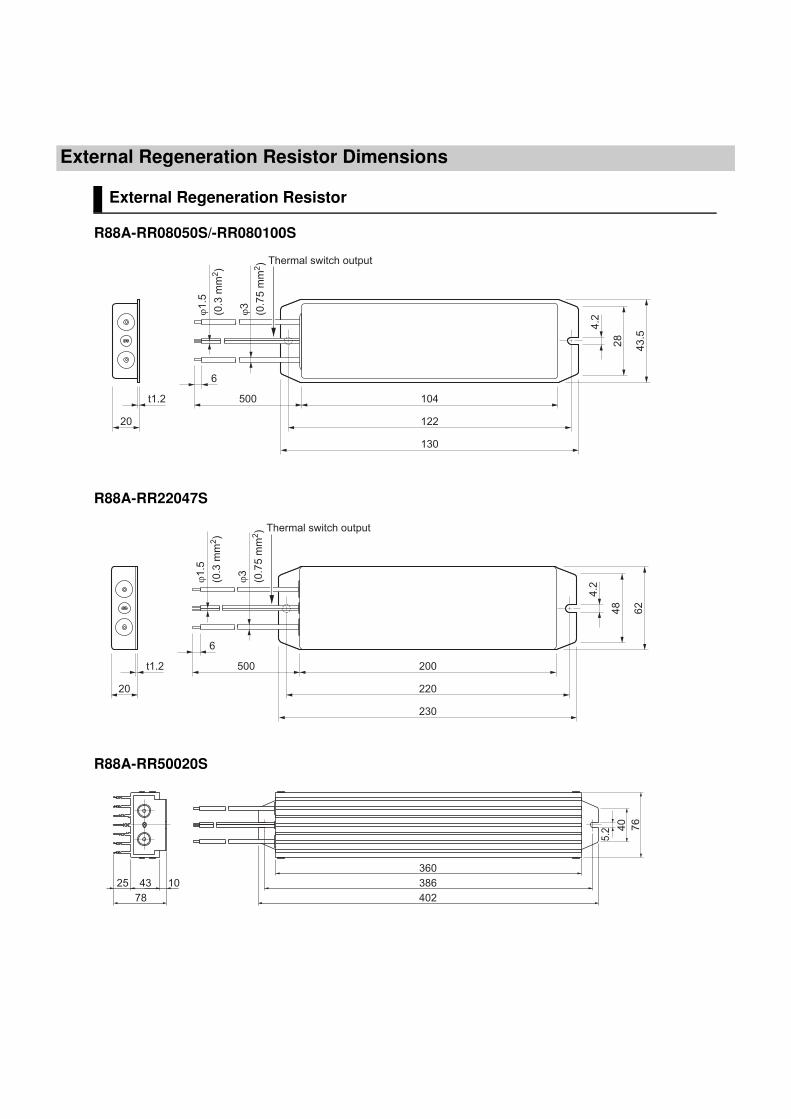
External Regeneration Resistor Dimensions
External Regeneration Resistor
R88A-RR08050S/-RR080100S
R88A-RR22047S
R88A-RR50020S
20
t1.2 104
122
130
43
.5
28
4.2
6
Thermal switch output
500
ϕ3
(0.7
5 m
m2)
ϕ1
.5
(0.3
mm
2)
20
t1.2 200
220
230
62
48
4.2
6
Thermal switch output
500
ϕ3
(0.7
5 m
m2)
ϕ1
.5
(0.3
mm
2)
360
386
402
4325 10
78
76
40
5.2
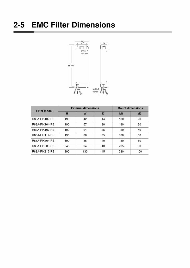
2-5 EMC Filter Dimensions
Filter modelExternal dimensions Mount dimensions
H W D M1 M2
R88A-FIK102-RE 190 42 44 180 20
R88A-FIK104-RE 190 57 30 180 30
R88A-FIK107-RE 190 64 35 180 40
R88A-FIK114-RE 190 86 35 180 60
R88A-FIK304-RE 190 86 40 180 60
R88A-FIK306-RE 245 94 40 235 60
R88A-FIK312-RE 290 130 45 280 100
H
WD
drive
mounts
M1
M2
output
flexes
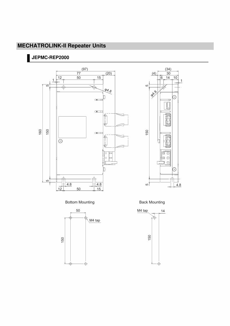
MECHATROLINK-II Repeater Units
JEPMC-REP2000
16
0
77 30
15
05
5
50 1512
15
0
155012
14 106
55
4.84.8 4.8
φ4.8
φ4.8
(20)
1 1
(97) (34)
(4)
50
15
0
14
15
0
M4 tap
M4 tap
Bottom Mounting Back Mounting
OMNUC G5-Series AC Servo Drives Users Manual (Built-in MECHATROLINK-II communications type)
3
3This chapter explains the general specifications, characteristics, connector
specifications and I/O circuits of the Servo Drives, as well as the general
specifications, characteristics, encoder specifications of the Servomotors.
3-1 Servo Drive Specifications ..........................................3-1
3-2 Overload Characteristics (Electronic Thermal Function) ... 3-31
3-3 Servomotor Specifications ........................................3-32
3-4 Cable and Connector Specifications ........................3-57
3-5 External Regeneration Resistor Specifications.......3-77
3-6 EMC Filter Specifications...........................................3-79
3-7 MECHATROLINK-II Repeater Unit Specifications....3-80
Specifications
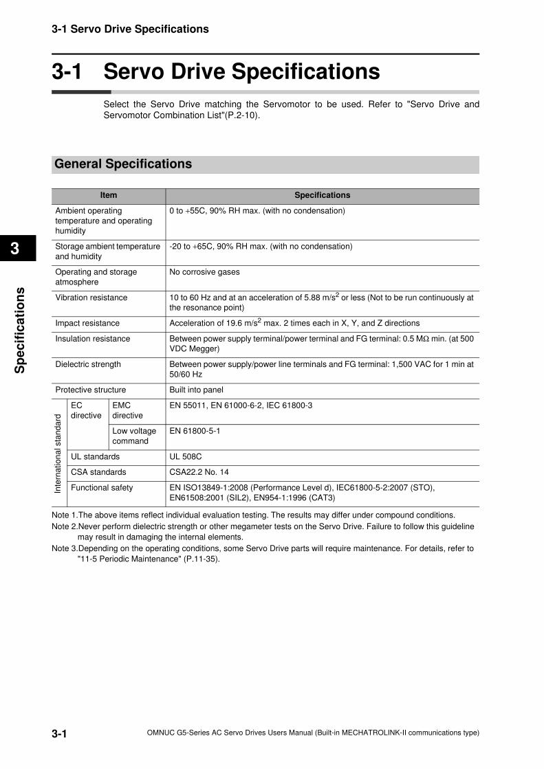
3-1
3-1 Servo Drive Specifications
OMNUC G5-Series AC Servo Drives Users Manual (Built-in MECHATROLINK-II communications type)
3
Sp
ecif
ica
tio
ns
3-1 Servo Drive Specifications
Select the Servo Drive matching the Servomotor to be used. Refer to "Servo Drive and
Servomotor Combination List"(P.2-10).
General Specifications
Note 1.The above items reflect individual evaluation testing. The results may differ under compound conditions.
Note 2.Never perform dielectric strength or other megameter tests on the Servo Drive. Failure to follow this guideline
may result in damaging the internal elements.
Note 3.Depending on the operating conditions, some Servo Drive parts will require maintenance. For details, refer to
"11-5 Periodic Maintenance" (P.11-35).
Item Specifications
Ambient operating
temperature and operating
humidity
0 to +55C, 90% RH max. (with no condensation)
Storage ambient temperature
and humidity
-20 to +65C, 90% RH max. (with no condensation)
Operating and storage
atmosphere
No corrosive gases
Vibration resistance 10 to 60 Hz and at an acceleration of 5.88 m/s2 or less (Not to be run continuously at
the resonance point)
Impact resistance Acceleration of 19.6 m/s2 max. 2 times each in X, Y, and Z directions
Insulation resistance Between power supply terminal/power terminal and FG terminal: 0.5 MΩ min. (at 500
VDC Megger)
Dielectric strength Between power supply/power line terminals and FG terminal: 1,500 VAC for 1 min at
50/60 Hz
Protective structure Built into panel
EC
directive
EMC
directive
EN 55011, EN 61000-6-2, IEC 61800-3
Low voltage
command
EN 61800-5-1
UL standards UL 508C
CSA standards CSA22.2 No. 14
Functional safety EN ISO13849-1:2008 (Performance Level d), IEC61800-5-2:2007 (STO),
EN61508:2001 (SIL2), EN954-1:1996 (CAT3)
Inte
rnation
al sta
nda
rd
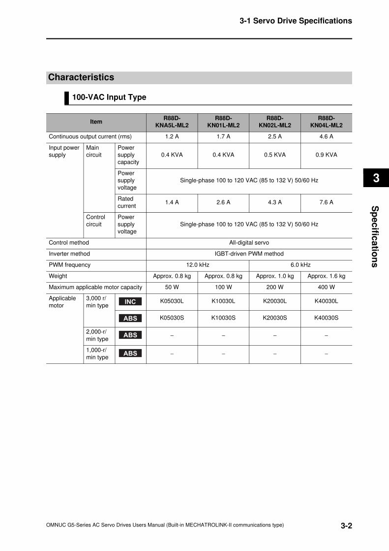
3-2
3-1 Servo Drive Specifications
OMNUC G5-Series AC Servo Drives Users Manual (Built-in MECHATROLINK-II communications type)
3
Sp
ec
ifica
tion
s
Characteristics
100-VAC Input Type
ItemR88D-
KNA5L-ML2
R88D-
KN01L-ML2
R88D-
KN02L-ML2
R88D-
KN04L-ML2
Continuous output current (rms) 1.2 A 1.7 A 2.5 A 4.6 A
Input power
supply
Main
circuit
Power
supply
capacity
0.4 KVA 0.4 KVA 0.5 KVA 0.9 KVA
Power
supply
voltage
Single-phase 100 to 120 VAC (85 to 132 V) 50/60 Hz
Rated
current1.4 A 2.6 A 4.3 A 7.6 A
Control
circuit
Power
supply
voltage
Single-phase 100 to 120 VAC (85 to 132 V) 50/60 Hz
Control method All-digital servo
Inverter method IGBT-driven PWM method
PWM frequency 12.0 kHz 6.0 kHz
Weight Approx. 0.8 kg Approx. 0.8 kg Approx. 1.0 kg Approx. 1.6 kg
Maximum applicable motor capacity 50 W 100 W 200 W 400 W
Applicable
motor
3,000 r/
min typeK05030L K10030L K20030L K40030L
K05030S K10030S K20030S K40030S
2,000-r/
min type− − − −
1,000-r/
min type− − − −
INC
ABS
ABS
ABS
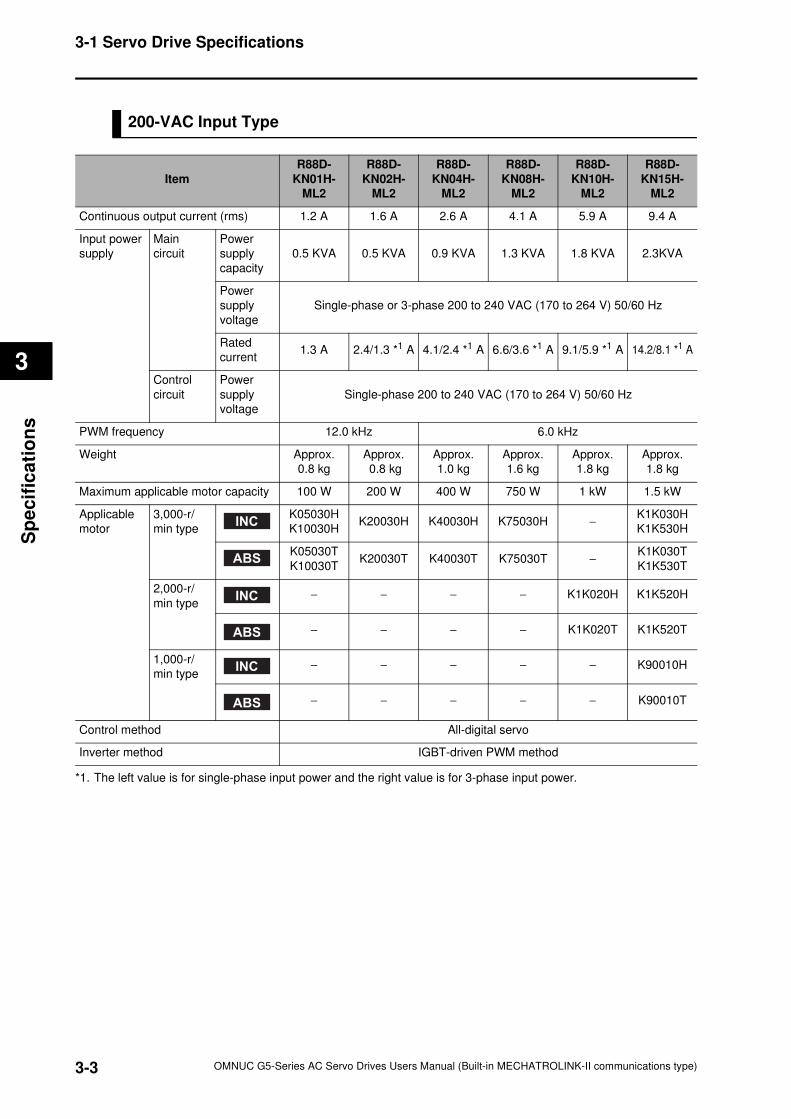
3-3
3-1 Servo Drive Specifications
OMNUC G5-Series AC Servo Drives Users Manual (Built-in MECHATROLINK-II communications type)
3
Sp
ecif
ica
tio
ns
200-VAC Input Type
*1. The left value is for single-phase input power and the right value is for 3-phase input power.
Item
R88D-
KN01H-
ML2
R88D-
KN02H-
ML2
R88D-
KN04H-
ML2
R88D-
KN08H-
ML2
R88D-
KN10H-
ML2
R88D-
KN15H-
ML2
Continuous output current (rms) 1.2 A 1.6 A 2.6 A 4.1 A 5.9 A 9.4 A
Input power
supply
Main
circuit
Power
supply
capacity
0.5 KVA 0.5 KVA 0.9 KVA 1.3 KVA 1.8 KVA 2.3KVA
Power
supply
voltage
Single-phase or 3-phase 200 to 240 VAC (170 to 264 V) 50/60 Hz
Rated
current1.3 A 2.4/1.3 *1 A 4.1/2.4 *1 A 6.6/3.6 *1 A 9.1/5.9 *1 A 14.2/8.1 *1 A
Control
circuit
Power
supply
voltage
Single-phase 200 to 240 VAC (170 to 264 V) 50/60 Hz
PWM frequency 12.0 kHz 6.0 kHz
Weight Approx.
0.8 kg
Approx.
0.8 kg
Approx.
1.0 kg
Approx.
1.6 kg
Approx.
1.8 kg
Approx.
1.8 kg
Maximum applicable motor capacity 100 W 200 W 400 W 750 W 1 kW 1.5 kW
Applicable
motor
3,000-r/
min type
K05030H
K10030HK20030H K40030H K75030H −
K1K030H
K1K530H
K05030T
K10030TK20030T K40030T K75030T −
K1K030T
K1K530T
2,000-r/
min type− − − − K1K020H K1K520H
− − − − K1K020T K1K520T
1,000-r/
min type− − − − − K90010H
− − − − − K90010T
Control method All-digital servo
Inverter method IGBT-driven PWM method
INC
ABS
INC
ABS
INC
ABS
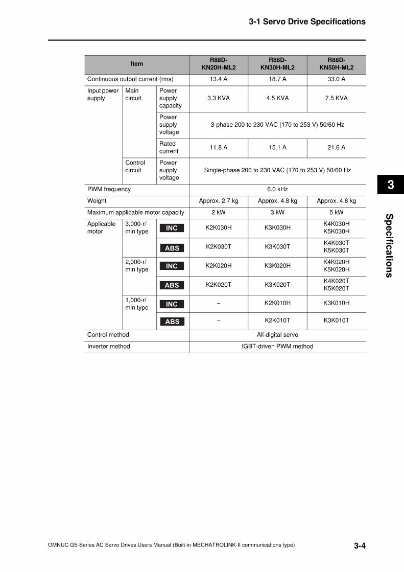
3-4
3-1 Servo Drive Specifications
OMNUC G5-Series AC Servo Drives Users Manual (Built-in MECHATROLINK-II communications type)
3
Sp
ec
ifica
tion
s
ItemR88D-
KN20H-ML2
R88D-
KN30H-ML2
R88D-
KN50H-ML2
Continuous output current (rms) 13.4 A 18.7 A 33.0 A
Input power
supply
Main
circuit
Power
supply
capacity
3.3 KVA 4.5 KVA 7.5 KVA
Power
supply
voltage
3-phase 200 to 230 VAC (170 to 253 V) 50/60 Hz
Rated
current11.8 A 15.1 A 21.6 A
Control
circuit
Power
supply
voltage
Single-phase 200 to 230 VAC (170 to 253 V) 50/60 Hz
PWM frequency 6.0 kHz
Weight Approx. 2.7 kg Approx. 4.8 kg Approx. 4.8 kg
Maximum applicable motor capacity 2 kW 3 kW 5 kW
Applicable
motor
3,000-r/
min typeK2K030H K3K030H
K4K030H
K5K030H
K2K030T K3K030TK4K030T
K5K030T
2,000-r/
min typeK2K020H K3K020H
K4K020H
K5K020H
K2K020T K3K020TK4K020T
K5K020T
1,000-r/
min type− K2K010H K3K010H
− K2K010T K3K010T
Control method All-digital servo
Inverter method IGBT-driven PWM method
INC
ABS
INC
ABS
INC
ABS
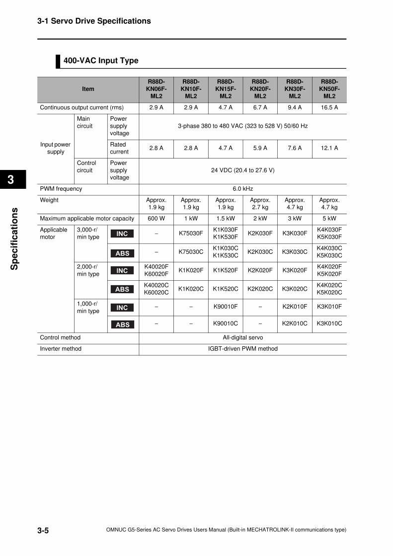
3-5
3-1 Servo Drive Specifications
OMNUC G5-Series AC Servo Drives Users Manual (Built-in MECHATROLINK-II communications type)
3
Sp
ecif
ica
tio
ns
400-VAC Input Type
Item
R88D-
KN06F-
ML2
R88D-
KN10F-
ML2
R88D-
KN15F-
ML2
R88D-
KN20F-
ML2
R88D-
KN30F-
ML2
R88D-
KN50F-
ML2
Continuous output current (rms) 2.9 A 2.9 A 4.7 A 6.7 A 9.4 A 16.5 A
Input power
supply
Main
circuit
Power
supply
voltage
3-phase 380 to 480 VAC (323 to 528 V) 50/60 Hz
Rated
current2.8 A 2.8 A 4.7 A 5.9 A 7.6 A 12.1 A
Control
circuit
Power
supply
voltage
24 VDC (20.4 to 27.6 V)
PWM frequency 6.0 kHz
Weight Approx.
1.9 kg
Approx.
1.9 kg
Approx.
1.9 kg
Approx.
2.7 kg
Approx.
4.7 kg
Approx.
4.7 kg
Maximum applicable motor capacity 600 W 1 kW 1.5 kW 2 kW 3 kW 5 kW
Applicable
motor
3,000-r/
min type− K75030F
K1K030F
K1K530FK2K030F K3K030F
K4K030F
K5K030F
− K75030CK1K030C
K1K530CK2K030C K3K030C
K4K030C
K5K030C
2,000-r/
min type
K40020F
K60020FK1K020F K1K520F K2K020F K3K020F
K4K020F
K5K020F
K40020C
K60020CK1K020C K1K520C K2K020C K3K020C
K4K020C
K5K020C
1,000-r/
min type− − K90010F − K2K010F K3K010F
− − K90010C − K2K010C K3K010C
Control method All-digital servo
Inverter method IGBT-driven PWM method
INC
ABS
INC
ABS
INC
ABS
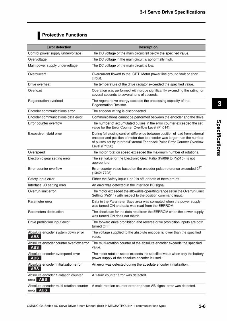
3-6
3-1 Servo Drive Specifications
OMNUC G5-Series AC Servo Drives Users Manual (Built-in MECHATROLINK-II communications type)
3
Sp
ec
ifica
tion
s
Protective Functions
Error detection Description
Control power supply undervoltage The DC voltage of the main circuit fell below the specified value.
Overvoltage The DC voltage in the main circuit is abnormally high.
Main power supply undervoltage The DC voltage of the main circuit is low.
Overcurrent Overcurrent flowed to the IGBT. Motor power line ground fault or short
circuit.
Drive overheat The temperature of the drive radiator exceeded the specified value.
Overload Operation was performed with torque significantly exceeding the rating for
several seconds to several tens of seconds.
Regeneration overload The regenerative energy exceeds the processing capacity of the
Regeneration Resistor.
Encoder communications error The encoder wiring is disconnected.
Encoder communications data error Communications cannot be performed between the encoder and the drive.
Error counter overflow The number of accumulated pulses in the error counter exceeded the set
value for the Error Counter Overflow Level (Pn014).
Excessive hybrid error During full closing control, difference between position of load from external
encoder and position of motor due to encoder was larger than the number
of pulses set by Internal/External Feedback Pulse Error Counter Overflow
Level (Pn328).
Overspeed The motor rotation speed exceeded the maximum number of rotations.
Electronic gear setting error The set value for the Electronic Gear Ratio (Pn009 to Pn010) is not
appropriate.
Error counter overflow Error counter value based on the encoder pulse reference exceeded 227
(134217728).
Safety input error Either the Safety input 1 or 2 is off, or both of them are off.
Interface I/O setting error An error was detected in the interface I/O signal.
Overrun limit error The motor exceeded the allowable operating range set in the Overrun Limit
Setting (Pn514) with respect to the position command input.
Parameter error Data in the Parameter Save area was corrupted when the power supply
was turned ON and data was read from the EEPROM.
Parameters destruction The checksum for the data read from the EEPROM when the power supply
was turned ON does not match.
Drive prohibition input error The forward drive prohibition and reverse drive prohibition inputs are both
turned OFF.
Absolute encoder system down error The voltage supplied to the absolute encoder is lower than the specified
value.
Absolute encoder counter overflow error The multi-rotation counter of the absolute encoder exceeds the specified
value.
Absolute encoder overspeed error The motor rotation speed exceeds the specified value when only the battery
power supply of the absolute encoder is used.
Absolute encoder initialization error An error was detected during the absolute encoder initialization.
Absolute encoder 1-rotation counter
error
A 1-turn counter error was detected.
Absolute encoder multi-rotation counter
error
A multi-rotation counter error or phase-AB signal error was detected.
ABS
ABS
ABS
ABS
ABS
ABS
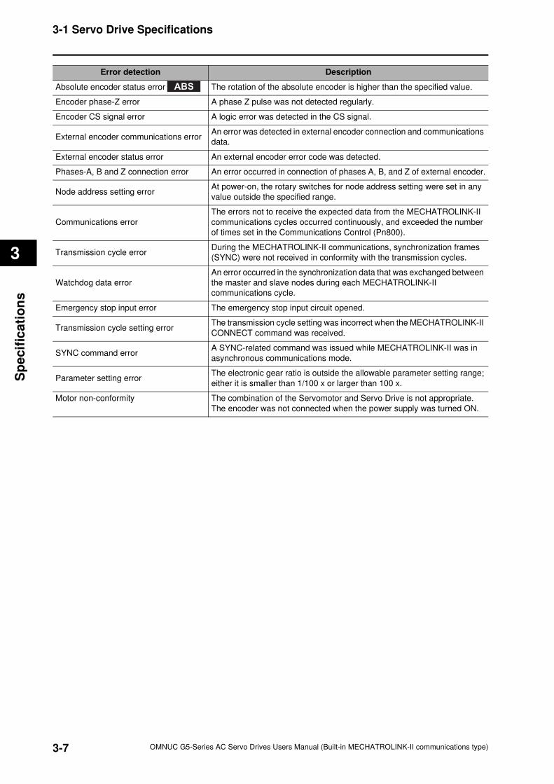
3-7
3-1 Servo Drive Specifications
OMNUC G5-Series AC Servo Drives Users Manual (Built-in MECHATROLINK-II communications type)
3
Sp
ecif
ica
tio
ns
Absolute encoder status error The rotation of the absolute encoder is higher than the specified value.
Encoder phase-Z error A phase Z pulse was not detected regularly.
Encoder CS signal error A logic error was detected in the CS signal.
External encoder communications errorAn error was detected in external encoder connection and communications
data.
External encoder status error An external encoder error code was detected.
Phases-A, B and Z connection error An error occurred in connection of phases A, B, and Z of external encoder.
Node address setting errorAt power-on, the rotary switches for node address setting were set in any
value outside the specified range.
Communications error
The errors not to receive the expected data from the MECHATROLINK-II
communications cycles occurred continuously, and exceeded the number
of times set in the Communications Control (Pn800).
Transmission cycle errorDuring the MECHATROLINK-II communications, synchronization frames
(SYNC) were not received in conformity with the transmission cycles.
Watchdog data error
An error occurred in the synchronization data that was exchanged between
the master and slave nodes during each MECHATROLINK-II
communications cycle.
Emergency stop input error The emergency stop input circuit opened.
Transmission cycle setting errorThe transmission cycle setting was incorrect when the MECHATROLINK-II
CONNECT command was received.
SYNC command errorA SYNC-related command was issued while MECHATROLINK-II was in
asynchronous communications mode.
Parameter setting errorThe electronic gear ratio is outside the allowable parameter setting range;
either it is smaller than 1/100 x or larger than 100 x.
Motor non-conformity The combination of the Servomotor and Servo Drive is not appropriate.
The encoder was not connected when the power supply was turned ON.
Error detection Description
ABS
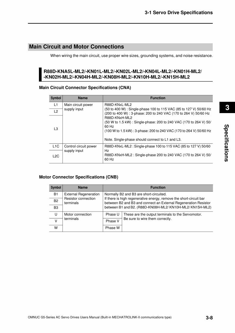
3-8
3-1 Servo Drive Specifications
OMNUC G5-Series AC Servo Drives Users Manual (Built-in MECHATROLINK-II communications type)
3
Sp
ec
ifica
tion
s
Main Circuit and Motor Connections
When wiring the main circuit, use proper wire sizes, grounding systems, and noise resistance.
R88D-KNA5L-ML2/-KN01L-ML2/-KN02L-ML2/-KN04L-ML2/-KN01H-ML2/-KN02H-ML2/-KN04H-ML2/-KN08H-ML2/-KN10H-ML2/-KN15H-ML2
Main Circuit Connector Specifications (CNA)
Motor Connector Specifications (CNB)
Symbol Name Function
L1 Main circuit power
supply input
R88D-KNxL-ML2
(50 to 400 W) : Single-phase 100 to 115 VAC (85 to 127 V) 50/60 Hz
(200 to 400 W) : 3-phase: 200 to 240 VAC (170 to 264 V) 50/60 Hz
R88D-KNxH-ML2
(50 W to 1.5 kW) : Single-phase: 200 to 240 VAC (170 to 264 V) 50/
60 Hz
(100 W to 1.5 kW) : 3-phase: 200 to 240 VAC (170 to 264 V) 50/60 Hz
Note. Single-phase should connect to L1 and L3.
L2
L3
L1C Control circuit power
supply input
R88D-KNxL-ML2 : Single-phase 100 to 115 VAC (85 to 127 V) 50/60
Hz
R88D-KNxH-ML2 : Single-phase 200 to 240 VAC (170 to 264 V) 50/
60 HzL2C
Symbol Name Function
B1 External Regeneration
Resistor connection
terminals
Normally B2 and B3 are short-circuited.
If there is high regenerative energy, remove the short-circuit bar
between B2 and B3 and connect an External Regeneration Resistor
between B1 and B2. (R88D-KN08H-ML2/ KN10H-ML2/ KN15H-ML2)
B2
B3
U Motor connection
terminals
Phase U These are the output terminals to the Servomotor.
Be sure to wire them correctly.V Phase V
W Phase W
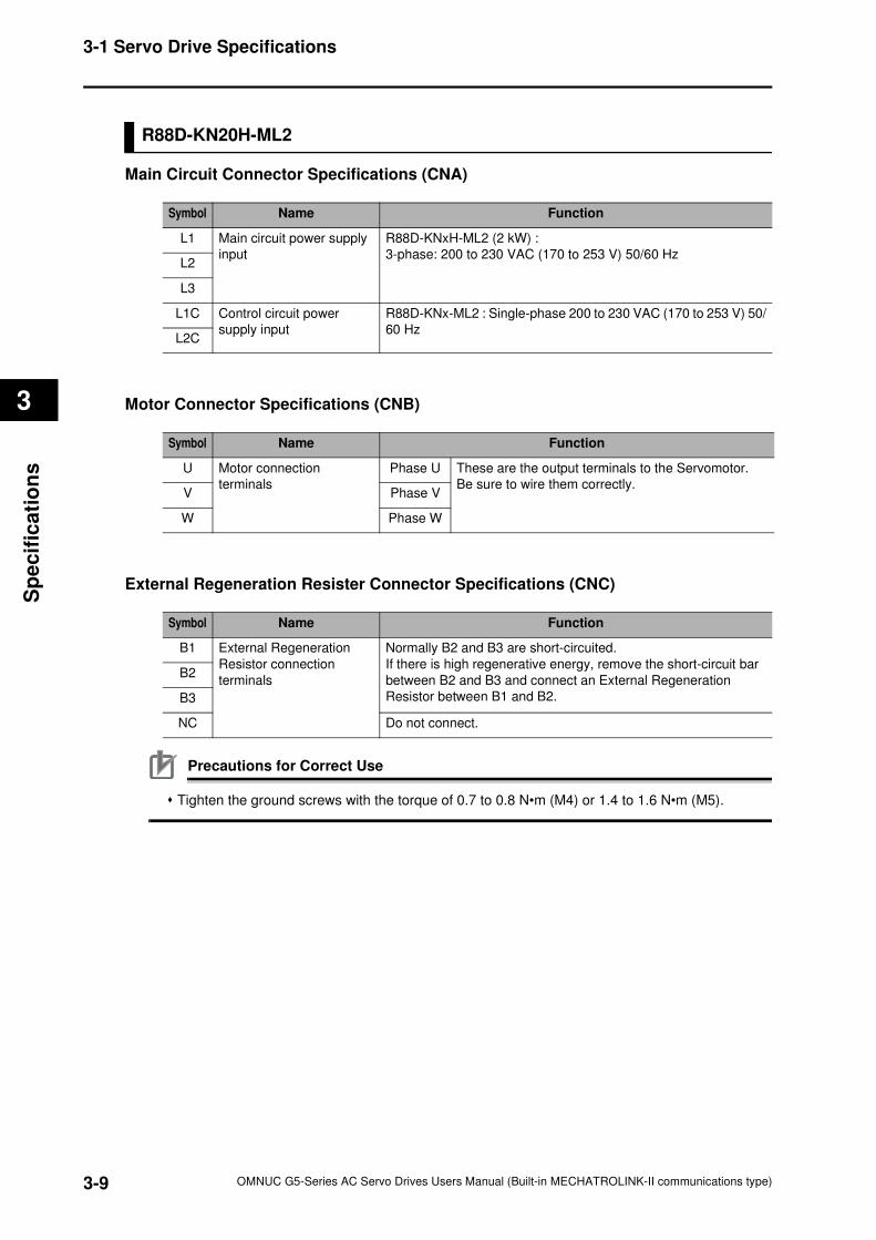
3-9
3-1 Servo Drive Specifications
OMNUC G5-Series AC Servo Drives Users Manual (Built-in MECHATROLINK-II communications type)
3
Sp
ecif
ica
tio
ns
R88D-KN20H-ML2
Main Circuit Connector Specifications (CNA)
Motor Connector Specifications (CNB)
External Regeneration Resister Connector Specifications (CNC)
Precautions for Correct Use
Tighten the ground screws with the torque of 0.7 to 0.8 N•m (M4) or 1.4 to 1.6 N•m (M5).
Symbol Name Function
L1 Main circuit power supply
input
R88D-KNxH-ML2 (2 kW) :
3-phase: 200 to 230 VAC (170 to 253 V) 50/60 HzL2
L3
L1C Control circuit power
supply input
R88D-KNx-ML2 : Single-phase 200 to 230 VAC (170 to 253 V) 50/
60 HzL2C
Symbol Name Function
U Motor connection
terminals
Phase U These are the output terminals to the Servomotor.
Be sure to wire them correctly.V Phase V
W Phase W
Symbol Name Function
B1 External Regeneration
Resistor connection
terminals
Normally B2 and B3 are short-circuited.
If there is high regenerative energy, remove the short-circuit bar
between B2 and B3 and connect an External Regeneration
Resistor between B1 and B2.
B2
B3
NC Do not connect.
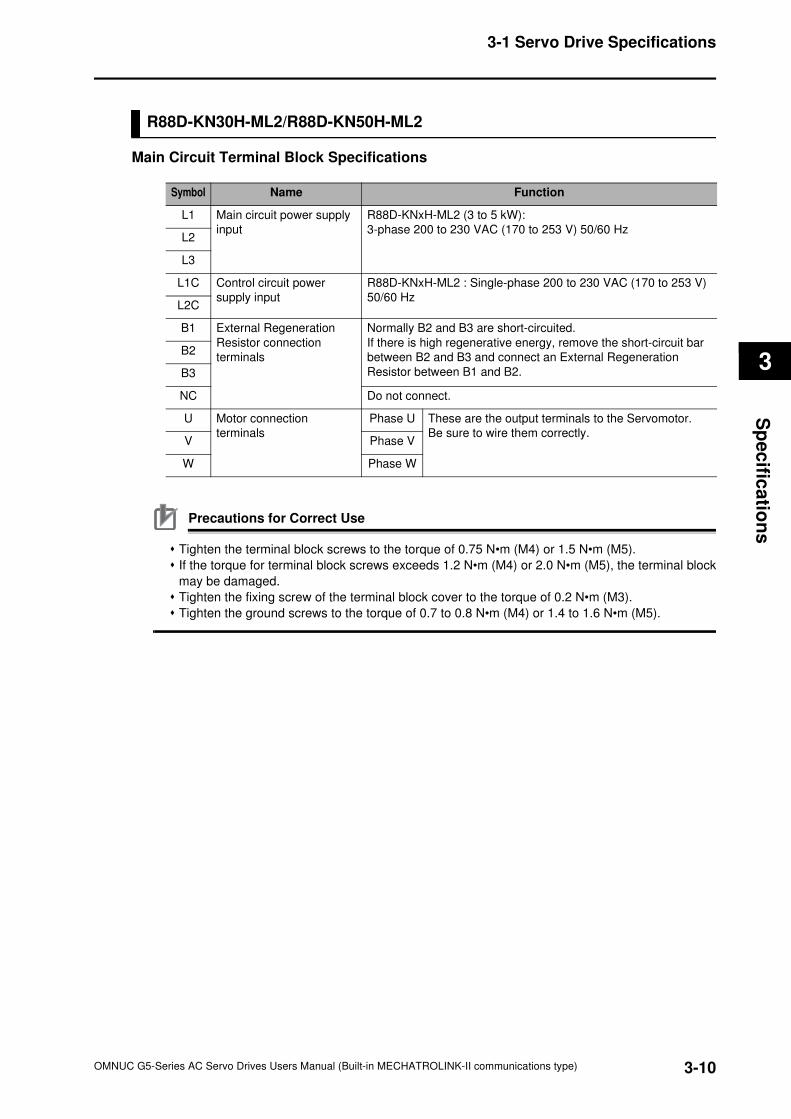
3-10
3-1 Servo Drive Specifications
OMNUC G5-Series AC Servo Drives Users Manual (Built-in MECHATROLINK-II communications type)
3
Sp
ec
ifica
tion
s
R88D-KN30H-ML2/R88D-KN50H-ML2
Main Circuit Terminal Block Specifications
Precautions for Correct Use
Tighten the terminal block screws to the torque of 0.75 N•m (M4) or 1.5 N•m (M5).
If the torque for terminal block screws exceeds 1.2 N•m (M4) or 2.0 N•m (M5), the terminal block
may be damaged.
Tighten the fixing screw of the terminal block cover to the torque of 0.2 N•m (M3).
Tighten the ground screws to the torque of 0.7 to 0.8 N•m (M4) or 1.4 to 1.6 N•m (M5).
Symbol Name Function
L1 Main circuit power supply
input
R88D-KNxH-ML2 (3 to 5 kW):
3-phase 200 to 230 VAC (170 to 253 V) 50/60 HzL2
L3
L1C Control circuit power
supply input
R88D-KNxH-ML2 : Single-phase 200 to 230 VAC (170 to 253 V)
50/60 Hz L2C
B1 External Regeneration
Resistor connection
terminals
Normally B2 and B3 are short-circuited.
If there is high regenerative energy, remove the short-circuit bar
between B2 and B3 and connect an External Regeneration
Resistor between B1 and B2.
B2
B3
NC Do not connect.
U Motor connection
terminals
Phase U These are the output terminals to the Servomotor.
Be sure to wire them correctly.V Phase V
W Phase W

3-11
3-1 Servo Drive Specifications
OMNUC G5-Series AC Servo Drives Users Manual (Built-in MECHATROLINK-II communications type)
3
Sp
ecif
ica
tio
ns
R88D-KN06F-ML2/-KN10F-ML2/-KN15F-ML2/-KN20F-ML2
Main Circuit Connector Specifications (CNA)
Motor Connector Specifications (CNB)
External Regeneration Resistor Connector Specifications (CNC)
Control Circuit Connector Specifications (CND)
Symbol Name Function
L1 Main circuit power supply
input
R88D-KNxF-ML2
(600 W to 2 kW) : 3-phase: 380 to 480 VAC (323 to 528 V)
50/60 HzL2
L3
Symbol Name Function
U Motor connection
terminals
Phase U These are the output terminals to the Servomotor.
Be sure to wire them correctly.V Phase V
W Phase W
Symbol Name Function
B1 External Regeneration
Resistor connection
terminals
Normally B2 and B3 are short-circuited.
If there is high regenerative energy, remove the short-circuit bar
between B2 and B3 and connect an External Regeneration
Resistor between B1 and B2.
B2
B3
NC Do not connect.
Symbol Name Function
24 V Control circuit power
supply input
24 VDC ± 15%
0 V
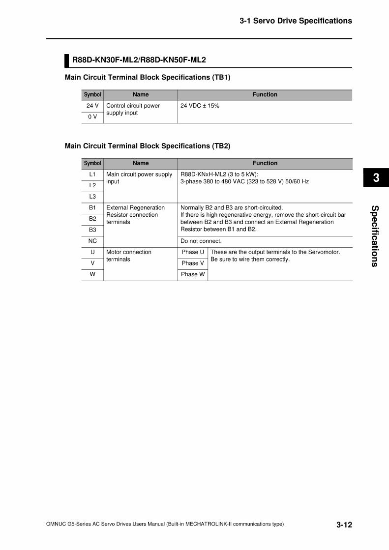
3-12
3-1 Servo Drive Specifications
OMNUC G5-Series AC Servo Drives Users Manual (Built-in MECHATROLINK-II communications type)
3
Sp
ec
ifica
tion
s
R88D-KN30F-ML2/R88D-KN50F-ML2
Main Circuit Terminal Block Specifications (TB1)
Main Circuit Terminal Block Specifications (TB2)
Symbol Name Function
24 V Control circuit power
supply input
24 VDC ± 15%
0 V
Symbol Name Function
L1 Main circuit power supply
input
R88D-KNxH-ML2 (3 to 5 kW):
3-phase 380 to 480 VAC (323 to 528 V) 50/60 HzL2
L3
B1 External Regeneration
Resistor connection
terminals
Normally B2 and B3 are short-circuited.
If there is high regenerative energy, remove the short-circuit bar
between B2 and B3 and connect an External Regeneration
Resistor between B1 and B2.
B2
B3
NC Do not connect.
U Motor connection
terminals
Phase U These are the output terminals to the Servomotor.
Be sure to wire them correctly.V Phase V
W Phase W
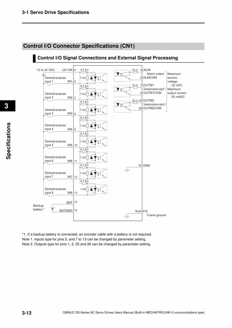
3-13
3-1 Servo Drive Specifications
OMNUC G5-Series AC Servo Drives Users Manual (Built-in MECHATROLINK-II communications type)
3
Sp
ecif
ica
tio
ns
Control I/O Connector Specifications (CN1)
Control I/O Signal Connections and External Signal Processing
*1. If a backup battery is connected, an encoder cable with a battery is not required.
Note 1. Inputs type for pins 5, and 7 to 13 can be changed by parameter setting.
Note 2. Outputs type for pins 1, 2, 25 and 26 can be changed by parameter setting.
General-purpose
input 1
/ALM
Alarm output
General-purpose output 1
General-purpose output 2
ALMCOM
3
4
OUTM1
OUTM1COM
OUTM2COM
1
2
OUTM225
26
12IN7
11IN6
10IN5
9IN4
8IN3
7IN2
5IN1
6+24 VIN
General-purpose
input 7
General-purpose
input 6
General-purpose
input 5
General-purpose
input 4
General-purpose
input 3
General-purpose
input 2
12 to 24 VDC
Maximum
service
voltage
: 30 VDC
Maximum
output current
: 50 mADC
13IN8
General-purpose
input 8
Frame ground
FGShell
4.7 kΩ
4.7 kΩ
4.7 kΩ
4.7 kΩ
4.7 kΩ
4.7 kΩ
4.7 kΩ
BAT
BATGND
Backup
battery*1
14
15
1 kΩ
4.7 kΩ
1 kΩ
1 kΩ
1 kΩ
1 kΩ
1 kΩ
1 kΩ
1 kΩ
16 GND
10 Ω
10 Ω
10 Ω
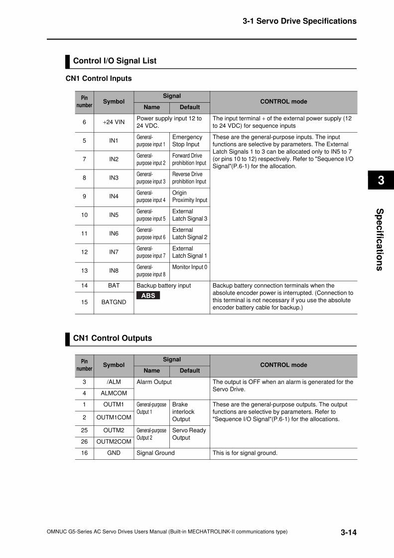
3-14
3-1 Servo Drive Specifications
OMNUC G5-Series AC Servo Drives Users Manual (Built-in MECHATROLINK-II communications type)
3
Sp
ec
ifica
tion
s
Control I/O Signal List
CN1 Control Inputs
CN1 Control Outputs
Pin
numberSymbol
SignalCONTROL mode
Name Default
6 +24 VINPower supply input 12 to
24 VDC.
The input terminal + of the external power supply (12
to 24 VDC) for sequence inputs
5 IN1General-
purpose input 1
Emergency
Stop Input
These are the general-purpose inputs. The input
functions are selective by parameters. The External
Latch Signals 1 to 3 can be allocated only to IN5 to 7
(or pins 10 to 12) respectively. Refer to "Sequence I/O
Signal"(P.6-1) for the allocation.7 IN2
General-
purpose input 2
Forward Drive
prohibition Input
8 IN3General-
purpose input 3
Reverse Drive
prohibition Input
9 IN4General-
purpose input 4
Origin
Proximity Input
10 IN5General-
purpose input 5
External
Latch Signal 3
11 IN6General-
purpose input 6
External
Latch Signal 2
12 IN7General-
purpose input 7
External
Latch Signal 1
13 IN8General-
purpose input 8
Monitor Input 0
14 BAT Backup battery input Backup battery connection terminals when the
absolute encoder power is interrupted. (Connection to
this terminal is not necessary if you use the absolute
encoder battery cable for backup.)15 BATGND
ABS
Pin
numberSymbol
SignalCONTROL mode
Name Default
3 /ALM Alarm Output The output is OFF when an alarm is generated for the
Servo Drive.4 ALMCOM
1 OUTM1 General-purpose
Output 1
Brake
interlock
Output
These are the general-purpose outputs. The output
functions are selective by parameters. Refer to
"Sequence I/O Signal"(P.6-1) for the allocations.2 OUTM1COM
25 OUTM2 General-purpose
Output 2
Servo Ready
Output26 OUTM2COM
16 GND Signal Ground This is for signal ground.
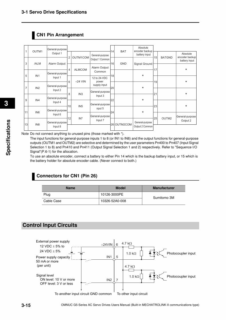
3-15
3-1 Servo Drive Specifications
OMNUC G5-Series AC Servo Drives Users Manual (Built-in MECHATROLINK-II communications type)
3
Sp
ecif
ica
tio
ns
CN1 Pin Arrangement
Note Do not connect anything to unused pins (those marked with *).
The input functions for general-purpose inputs 1 to 8 (or IN1 to IN8) and the output functions for general-purpose
outputs (OUTM1 and OUTM2) are selective and determined by the user parameters Pn400 to Pn407 (Input Signal
Selection 1 to 8) and Pn410 and Pn411 (Output Signal Selection 1 and 2) respectively. Refer to "Sequence I/O
Signal"(P.6-1) for the allocation.
To use an absolute encoder, connect a battery to either Pin 14 which is the backup battery input, or 15 which is
the battery holder for absolute encoder cable. (Never connect to both.)
Connectors for CN1 (Pin 26)
Control Input Circuits
Name Model Manufacturer
Plug 10126-3000PESumitomo 3M
Cable Case 10326-52A0-008
1
3
5
7
9
11
13
2
4
6
8
10
12
14
16
18
20
22
24
26
15
17
19
21
23
25
IN2
IN1
OUTM1
*
BAT
BATGND
OUTM2
ALMCOM
/ALM
IN8
IN3
IN4
IN5
IN6
IN7
OUTM1COM
*
GND
OUTM2COM
*
*
*
*
*
*
General-purpose
Output 2 Common
General-purpose
Input 2
General-purpose
Output 1General-purpose
Output 1 Common
+24 VIN
Absolute
encoder backup
battery input
Absolute
encoder backup
battery input
12 to 24-VDC
power
supply input
General-purpose
Output 2
Alarm Output
Common
Alarm Output
General-purpose
Input 8
General-purpose
Input 4General-purpose
nput 5General-purpose
Input 6General-purpose
Input 7
Signal Ground
General-purpose
Input 1
General-purpose
Input 3
4.7 kΩ
1.0 kΩ
5
7
IN1
IN2
6+24VIN
To other input circuit
External power supply
12 VDC ± 5% to
24 VDC ± 5%
Power supply capacity
50 mA or more
(per unit)
Signal level
ON level: 10 V or more
OFF level: 3 V or less
To another input circuit GND common
Photocoupler input
4.7 kΩ
1.0 kΩ Photocoupler input
3-16
3-1 Servo Drive Specifications
OMNUC G5-Series AC Servo Drives Users Manual (Built-in MECHATROLINK-II communications type)
3
Sp
ec
ifica
tion
s
Control Input Details
This is the detailed information about the CN1 Connector input pins.
General-purpose Inputs (IN1 to IN8)
Refer to "Sequence I/O Signal"(P.6-1) for the allocation procedures.
Emergency Stop Input (STOP)
It is used when an external sequence such as the host forcibly turns off the servo.
If the input is turned off during the Servomotor rotation, the dynamic brake makes a deceleration
stop. After the motor stops, it remains in servo-free state.
If the Emergency Stop Input (STOP) is ON during the motor is energized, the Force alarm input
error (Alarm No.87.0) occurs.
It is allocated to the pin 5 at factory setting.
Precautions for Safe Use
Turn OFF the Emergency Stop Input (STOP) at the same time when you turn OFF the main
power. When the main power becomes OFF due to an external emergency stop reason, the
motor continues rotation for residual voltage. This may cause human injuries or damages on
the machine and devices.
Pin 5 : General-purpose Input 1 (IN1)
Pin 7 : General-purpose Input 2 (IN2)
Pin 8 : General-purpose Input 3 (IN3)
Pin 9 : General-purpose Input 4 (IN4)
Pin 10 : General-purpose Input 5 (IN5)
Pin 11 : General-purpose Input 6 (IN6)
Pin 12 : General-purpose Input 7 (IN7)
Pin 13 : General-purpose Input 8 (IN8)
3-17
3-1 Servo Drive Specifications
OMNUC G5-Series AC Servo Drives Users Manual (Built-in MECHATROLINK-II communications type)
3
Sp
ecif
ica
tio
ns
]
Forward Drive Prohibition Input (POT) and Reverse Drive Prohibition Input (NOT)
The two signals are the inputs to prohibit forward and reverse rotation (over-travel inputs).
When one input is ON, the Servo Drive can rotate in the specified direction.
In the Drive Prohibition state, Servomotor switches to servo lock state after deceleration stop.
The maximum torque at deceleration stop is the same as the maximum servomotor torque.
In the Drive Prohibition state, the Servo Drive does not switch to an alarming state.
When the Drive Prohibition Input Selection (Pn504) is set to 1, the operation at a drive prohibit
input can be selected on the Stop Selection for Drive Prohibition Input (Pn505).
When the Drive Prohibition Input Selection (Pn504) is set to 2, the Drive Prohibition Input
Protection (E380) works at a drive prohibition input.
In factory setting, the Forward Drive Prohibition Input (POT) is allocated to Pin 7, while the
Reverse Drive Prohibition Input (NOT) is to Pin 8.
Reference
In factory setting, both inputs are set to Disabled (in a state to disable the drive prohibition).
The setting can be changed by the Drive Prohibit Input Selection (Pn504). The setting on the
Input Signal Selection 1 to 10 (Pn400 to Pn409) can change the theory and allocation for the
respective Input terminals (CN1 to 7 and 8).
Origin Proximity Input (DEC)
This is the deceleration signal at origin searches.
When the Origin Proximity Input is ON while the Servomotor travels at the origin search feed
speed, it decelerates to the origin search approach speed.
When the first origin input is entered after the Origin Proximity Input turns OFF, the Servomotor
decelerates to the origin search creep speed, and controls positions for the origin search final
travel distance.
After positioning completes, the position is the origin.
In factory setting, the Origin Proximity Input is assigned to Pin 9.
Precautions for Correct Use
The Origin Proximity Input (DEC) signals can be entered in the speed control mode and the
torque control mode. However, the inputs do not relate the operation.
External Latch Input Signals (EX1, EX2 and EX3)
These are the external input signals to latch the present value on the feedback pulse counter.
The Encoder position data is obtained at the moment when the External Latch Input is turned on.
In factory setting, the External Latch Input 1 is allocated to Pin 12, the External Latch Input 2 to
Pin 11, and the External Latch Input 3 to Pin 10.
Precautions for Correct Use
The external latch inputs are detected by signal raises. The minimal signal width must be 1 ms.
The external latch inputs can only be set to NO (normally open) contact.
The external latch inputs can be allocated to pins 10 to 12 only.
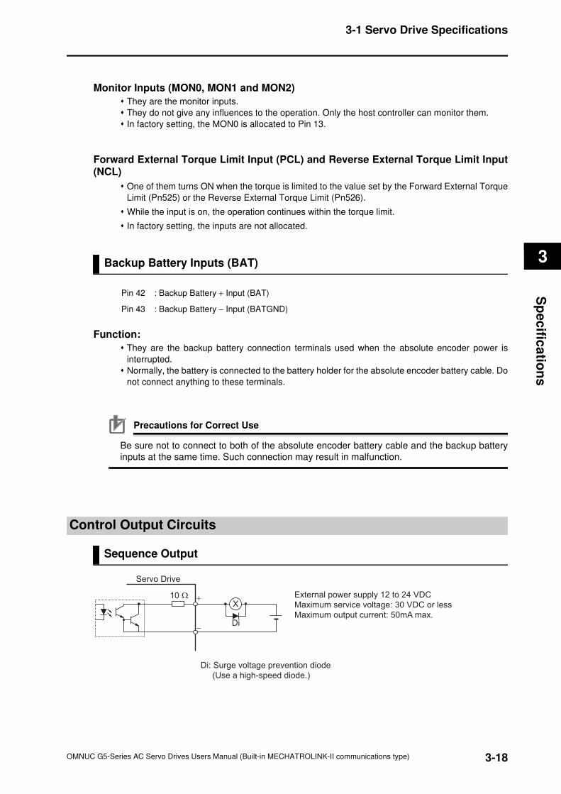
3-18
3-1 Servo Drive Specifications
OMNUC G5-Series AC Servo Drives Users Manual (Built-in MECHATROLINK-II communications type)
3
Sp
ec
ifica
tion
s
Monitor Inputs (MON0, MON1 and MON2)
They are the monitor inputs.
They do not give any influences to the operation. Only the host controller can monitor them.
In factory setting, the MON0 is allocated to Pin 13.
Forward External Torque Limit Input (PCL) and Reverse External Torque Limit Input(NCL)
One of them turns ON when the torque is limited to the value set by the Forward External Torque
Limit (Pn525) or the Reverse External Torque Limit (Pn526).
While the input is on, the operation continues within the torque limit.
In factory setting, the inputs are not allocated.
Backup Battery Inputs (BAT)
Function:
They are the backup battery connection terminals used when the absolute encoder power is
interrupted.
Normally, the battery is connected to the battery holder for the absolute encoder battery cable. Do
not connect anything to these terminals.
Precautions for Correct Use
Be sure not to connect to both of the absolute encoder battery cable and the backup battery
inputs at the same time. Such connection may result in malfunction.
Control Output Circuits
Sequence Output
Pin 42 : Backup Battery + Input (BAT)
Pin 43 : Backup Battery − Input (BATGND)
−
X
Di
+
Di: Surge voltage prevention diode
(Use a high-speed diode.)
External power supply 12 to 24 VDC
Maximum service voltage: 30 VDC or less
Maximum output current: 50mA max.
Servo Drive
10 Ω
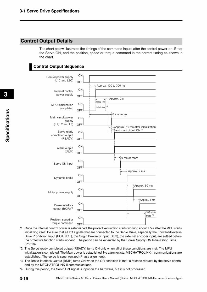
3-19
3-1 Servo Drive Specifications
OMNUC G5-Series AC Servo Drives Users Manual (Built-in MECHATROLINK-II communications type)
3
Sp
ecif
ica
tio
ns
Control Output Details
The chart below illustrates the timings of the command inputs after the control power-on. Enter
the Servo ON, and the position, speed or torque command in the correct timing as shown in
the chart.
Control Output Sequence
*1. Once the internal control power is established, the protective function starts working about 1.5 s after the MPU starts
initializing itself. Be sure that all I/O signals that are connected to the Servo Drive, especially the Forward/Reverse
Drive Prohibition Input (POT/NOT), the Origin Proximity Input (DEC), the external encoder input, are settled before
the protective function starts working. The period can be extended by the Power Supply ON Initialization Time
(Pn618).
*2. The Servo ready completed output (READY) turns ON only when all of these conditions are met: The MPU
initialization is completed. The Main power is established. No alarm exists. MECHATROLINK-II communications are
established. The servo is synchronized (Phase alignment).
*3. The Brake Interlock Output (BKIR) turns ON when the OR condition is met: a release request by the servo control
and by the MECHATROLINK-II communications.
*4. During this period, the Servo ON signal is input on the hardware, but it is not processed.
Control power supply
(L1C and L2C)
Internal control
power supply
MPU initialization
completed
Main circuit power
supply
(L1, L2 and L3)
Servo ready
completed output
(READY)
Alarm output
(/ALM)
ON
OFF
ON
OFF
ON
OFF
ON
OFF
ON
OFF
ON
OFF
Approx. 100 to 300 ms
Approx. 2 sApprox. 1.5 s
Iinitialization *1
Approx. 10 ms after initialization
and main circuit ON *2
Servo ON input
Dynamic brake
Motor power supply
Brake interlock
output (BKIR) *3
Position, speed or
torque command
ON
OFF
ON
OFF
ON
OFF
ON
OFF
ON
OFF
Approx. 60 ms
Approx. 2 ms
Approx. 4 ms
0 ms or more
0 s or more
100 ms or
more *4
3-20
3-1 Servo Drive Specifications
OMNUC G5-Series AC Servo Drives Users Manual (Built-in MECHATROLINK-II communications type)
3
Sp
ec
ifica
tion
s
Alarm Output (/ALM)
Pin 3: Alarm Output (/ALM)
Pin 4: Alarm output common (ALMCOM)
Function
The output is turned OFF when the drive detects an error.
This output is OFF at power supply ON, but turns ON when the drive's initial processing has
been completed.
General-purpose Output (OUTM1 and OUTM2)
Refer to the description in Output Signals in Section "Sequence I/O Signal"(P.6-1) for the
allocation.
Servo Ready Completed Output (READY)
The output signal indicates the Drive is ready to be energized.
It turns ON when no error is detected after main circuit power-ON.
In factory setting, the Outputs are allocated to Pin 25 and 26.
Brake Interlock Output (BKIR)
It outputs the external brake timing signal as set by the Brake Timing when Stopped (Pn437), the
Brake Timing During Operation (Pn438), and the Brake Release Speed Setting (Pn439).
In factory setting, the Outputs are allocated to Pin 1 and 2.
Positioning Completion Output 1 (INP1) and Positioning Completion Output 2 (INP2)
The INP1 turns ON when the error counter accumulated pulse is less than or equal to the
Positioning Completion Range 1 (Pn431) set value.
The INP2 turns ON when the error counter accumulated pulse is less than or equal to the
Positioning Completion Range 2 (Pn442) set value.
The output turns ON according to Positioning Completion Condition Selection (Pn432).
The output is always OFF except in the POSITION CONTROL mode (including the FULL
CLOSING CONTROL mode).
In factory setting, the output is not allocated.
Pin 1 : General-purpose Output 1 (OUTM1)
Pin 2 : General-purpose Output 1 Common (OUTM1COM)
Pin 25 : General-purpose Output 2 (OUTM2)
Pin 26 : General-purpose Output 2 Common (OUTM2COM)
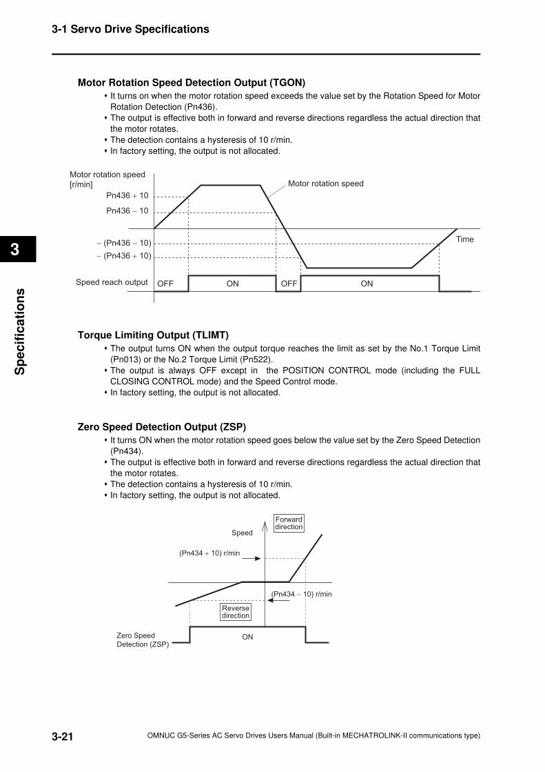
3-21
3-1 Servo Drive Specifications
OMNUC G5-Series AC Servo Drives Users Manual (Built-in MECHATROLINK-II communications type)
3
Sp
ecif
ica
tio
ns
Motor Rotation Speed Detection Output (TGON)
It turns on when the motor rotation speed exceeds the value set by the Rotation Speed for Motor
Rotation Detection (Pn436).
The output is effective both in forward and reverse directions regardless the actual direction that
the motor rotates.
The detection contains a hysteresis of 10 r/min.
In factory setting, the output is not allocated.
Torque Limiting Output (TLIMT)
The output turns ON when the output torque reaches the limit as set by the No.1 Torque Limit
(Pn013) or the No.2 Torque Limit (Pn522).
The output is always OFF except in the POSITION CONTROL mode (including the FULL
CLOSING CONTROL mode) and the Speed Control mode.
In factory setting, the output is not allocated.
Zero Speed Detection Output (ZSP)
It turns ON when the motor rotation speed goes below the value set by the Zero Speed Detection
(Pn434).
The output is effective both in forward and reverse directions regardless the actual direction that
the motor rotates.
The detection contains a hysteresis of 10 r/min.
In factory setting, the output is not allocated.
Motor rotation speed
[r/min] Motor rotation speed
Time
Pn436 + 10
Speed reach output
Pn436 − 10
− (Pn436 − 10)
− (Pn436 + 10)
OFF OFFON ON
Speed
Reversedirection
ON
(Pn434 + 10) r/min
Forwarddirection
(Pn434 − 10) r/min
Zero Speed
Detection (ZSP)
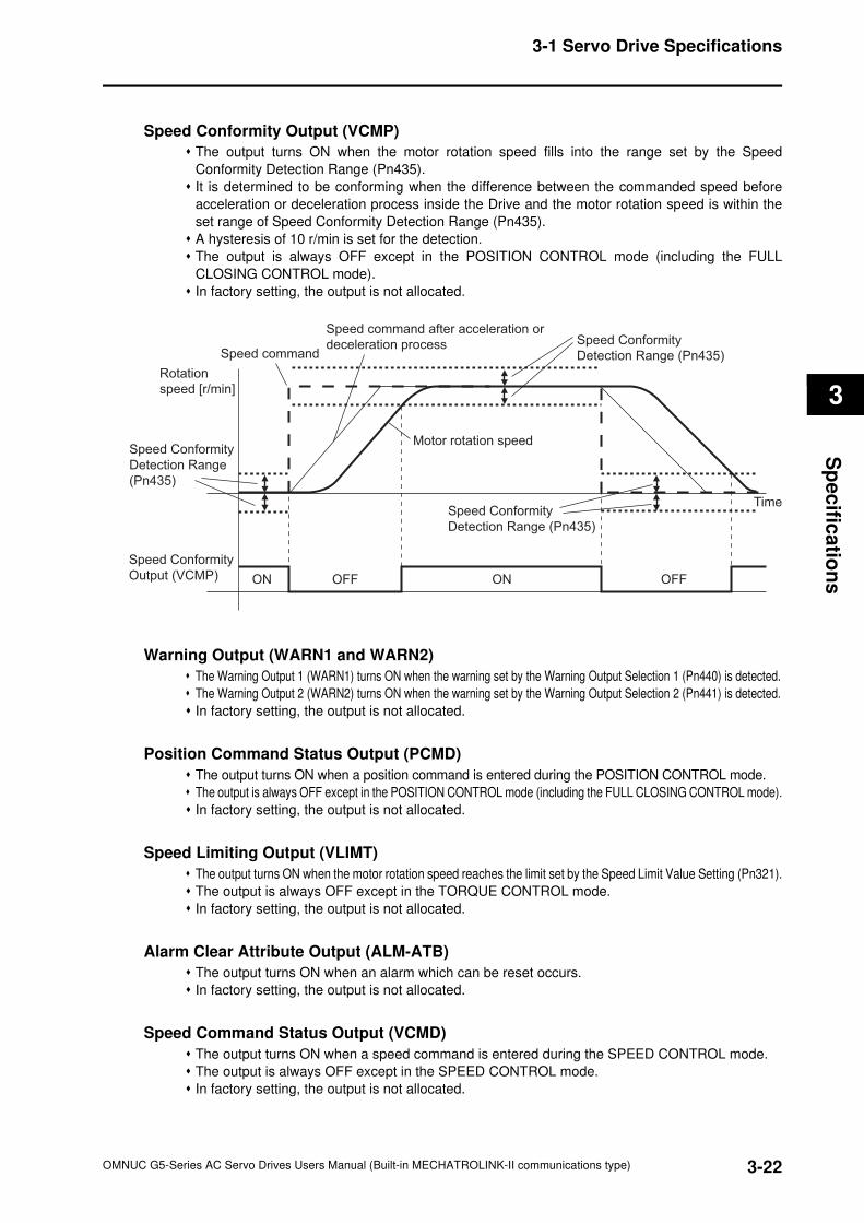
3-22
3-1 Servo Drive Specifications
OMNUC G5-Series AC Servo Drives Users Manual (Built-in MECHATROLINK-II communications type)
3
Sp
ec
ifica
tion
s
Speed Conformity Output (VCMP)
The output turns ON when the motor rotation speed fills into the range set by the Speed
Conformity Detection Range (Pn435).
It is determined to be conforming when the difference between the commanded speed before
acceleration or deceleration process inside the Drive and the motor rotation speed is within the
set range of Speed Conformity Detection Range (Pn435).
A hysteresis of 10 r/min is set for the detection.
The output is always OFF except in the POSITION CONTROL mode (including the FULL
CLOSING CONTROL mode).
In factory setting, the output is not allocated.
Warning Output (WARN1 and WARN2)
The Warning Output 1 (WARN1) turns ON when the warning set by the Warning Output Selection 1 (Pn440) is detected.
The Warning Output 2 (WARN2) turns ON when the warning set by the Warning Output Selection 2 (Pn441) is detected.
In factory setting, the output is not allocated.
Position Command Status Output (PCMD)
The output turns ON when a position command is entered during the POSITION CONTROL mode.
The output is always OFF except in the POSITION CONTROL mode (including the FULL CLOSING CONTROL mode).
In factory setting, the output is not allocated.
Speed Limiting Output (VLIMT)
The output turns ON when the motor rotation speed reaches the limit set by the Speed Limit Value Setting (Pn321).
The output is always OFF except in the TORQUE CONTROL mode.
In factory setting, the output is not allocated.
Alarm Clear Attribute Output (ALM-ATB)
The output turns ON when an alarm which can be reset occurs.
In factory setting, the output is not allocated.
Speed Command Status Output (VCMD)
The output turns ON when a speed command is entered during the SPEED CONTROL mode.
The output is always OFF except in the SPEED CONTROL mode.
In factory setting, the output is not allocated.
Rotation
speed [r/min]
Speed command after acceleration or
deceleration processSpeed command
Motor rotation speed
ON ONOFF OFF
Speed Conformity
Detection Range
(Pn435)
Speed Conformity
Detection Range (Pn435)
Speed Conformity
Detection Range (Pn435)
Time
Speed Conformity
Output (VCMP)
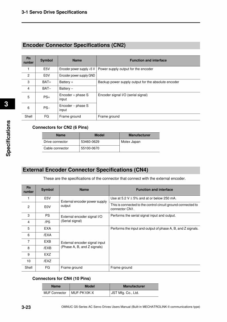
3-23
3-1 Servo Drive Specifications
OMNUC G5-Series AC Servo Drives Users Manual (Built-in MECHATROLINK-II communications type)
3
Sp
ecif
ica
tio
ns
Encoder Connector Specifications (CN2)
Connectors for CN2 (6 Pins)
External Encoder Connector Specifications (CN4)
These are the specifications of the connector that connect with the external encoder.
Connectors for CN4 (10 Pins)
Pin
numberSymbol Name Function and interface
1 E5V Encoder power supply +5 V Power supply output for the encoder
2 E0V Encoder power supply GND
3 BAT+ Battery + Backup power supply output for the absolute encoder
4 BAT− Battery −
5 PS+Encoder + phase S
input
Encoder signal I/O (serial signal)
6 PS−Encoder − phase S
input
Shell FG Frame ground Frame ground
Name Model Manufacturer
Drive connector 53460-0629 Molex Japan
Cable connector 55100-0670
Pin
numberSymbol Name Function and interface
1 E5VExternal encoder power supply
output
Use at 5.2 V ± 5% and at or below 250 mA.
2 E0VThis is connected to the control circuit ground connected to
connector CN1.
3 PS External encoder signal I/O
(Serial signal)
Performs the serial signal input and output.
4 /PS
5 EXA
External encoder signal input
(Phase A, B, and Z signals)
Performs the input and output of phase A, B, and Z signals.
6 /EXA
7 EXB
8 /EXB
9 EXZ
10 /EXZ
Shell FG Frame ground Frame ground
Name Model Manufacturer
MUF Connector MUF-PK10K-X JST Mfg. Co., Ltd.
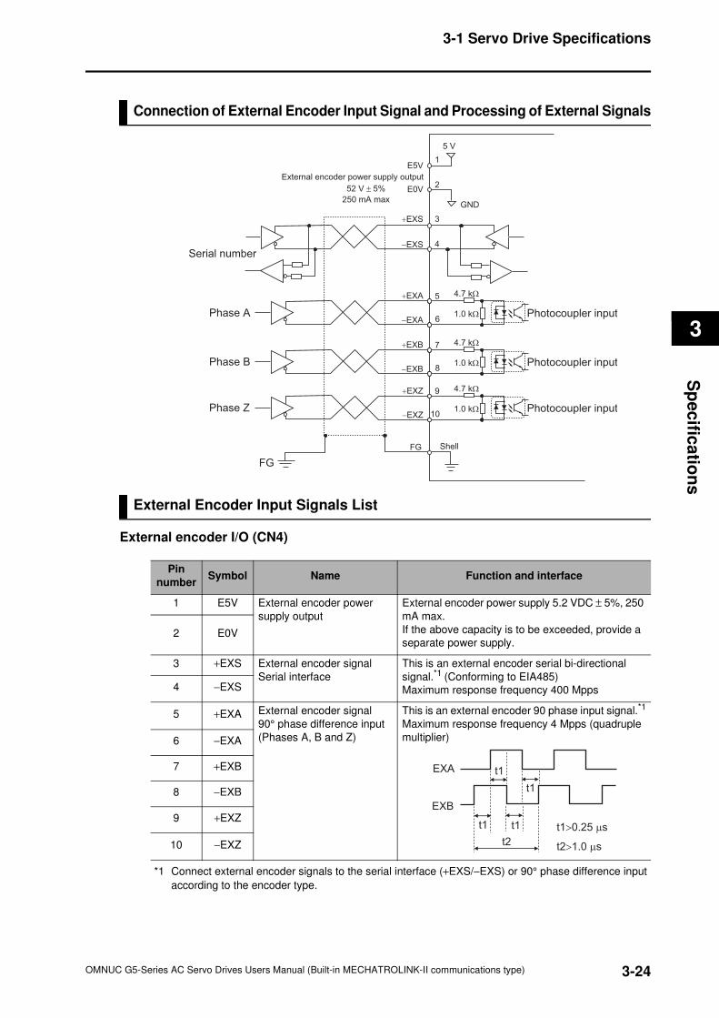
3-24
3-1 Servo Drive Specifications
OMNUC G5-Series AC Servo Drives Users Manual (Built-in MECHATROLINK-II communications type)
3
Sp
ec
ifica
tion
s
Connection of External Encoder Input Signal and Processing of External Signals
External Encoder Input Signals List
External encoder I/O (CN4)
*1 Connect external encoder signals to the serial interface (+EXS/−EXS) or 90° phase difference input
according to the encoder type.
Phase A Photocoupler input
+EXA
+EXS
E0V
E5V
5 V
−EXS
−EXA
5
1
2
3
4
6
4.7 kΩ
1.0 kΩ
Phase B Photocoupler input
+EXB
−EXB
7
8
4.7 kΩ
1.0 kΩ
Phase Z Photocoupler input
+EXZ
−EXZ
9
10
4.7 kΩ
1.0 kΩ
ShellFG
FG
GND
External encoder power supply output
52 V ± 5%
250 mA max
Serial number
Pin
numberSymbol Name Function and interface
1 E5V External encoder power
supply output
External encoder power supply 5.2 VDC ± 5%, 250
mA max.
If the above capacity is to be exceeded, provide a
separate power supply.2 E0V
3 +EXS External encoder signal
Serial interface
This is an external encoder serial bi-directional
signal.*1 (Conforming to EIA485)
Maximum response frequency 400 Mpps4 −EXS
5 +EXA External encoder signal
90° phase difference input
(Phases A, B and Z)
This is an external encoder 90 phase input signal.*1
Maximum response frequency 4 Mpps (quadruple
multiplier)6 −EXA
7 +EXB
8 −EXB
9 +EXZ
10 −EXZ
EXA
EXB
t1 t1
t1
t1
t2
t1>0.25 µs
t2>1.0 µs
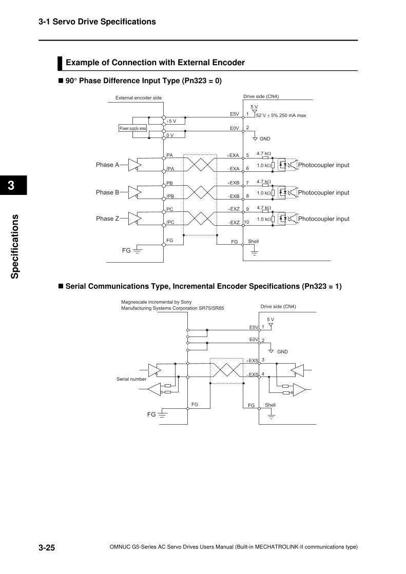
3-25
3-1 Servo Drive Specifications
OMNUC G5-Series AC Servo Drives Users Manual (Built-in MECHATROLINK-II communications type)
3
Sp
ecif
ica
tio
ns
Example of Connection with External Encoder
90° Phase Difference Input Type (Pn323 = 0)
Serial Communications Type, Incremental Encoder Specifications (Pn323 = 1)
52 V ± 5% 250 mA max
Phase Z Photocoupler input
+EXZ
−EXZ
9
10
4.7 kΩ
1.0 kΩ
Phase A Photocoupler input−EXA
+EXA
GND
E5V
5 V
E0V
6
5
2
1
1.0 kΩ
Phase B Photocoupler input
+EXB
−EXB
7
8
4.7 kΩ
4.7 kΩ
1.0 kΩ
ShellFG
FG
+5 V
0 V
PA
/PA
PB
/PB
PC
/PC
FG
Drive side (CN4)External encoder side
Power supply area
+EXS
−EXS
GND
E5V
5 V
E0V 2
3
4
1
ShellFG
Drive side (CN4)
FG
FG
Serial number
Magnescale incremental by Sony
Manufacturing Systems Corporation SR75/SR85
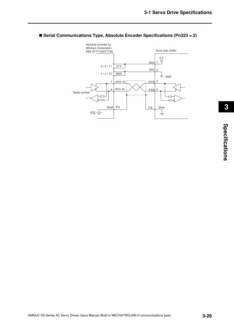
3-26
3-1 Servo Drive Specifications
OMNUC G5-Series AC Servo Drives Users Manual (Built-in MECHATROLINK-II communications type)
3
Sp
ec
ifica
tion
s
Serial Communications Type, Absolute Encoder Specifications (Pn323 = 2)
+EXS+REQ/+SD
−REQ/+SD−EXS
GNDGND
E5V
5 V
E0V 2
37
8 4
1
ShellShell FG
Drive side (CN4)
FG
FG
Serial number
Absolute encoder by
Mitutoyo Corporation
ABS ST771A/ST773A
+5 V3 • 4 • 11
1 • 2 • 13
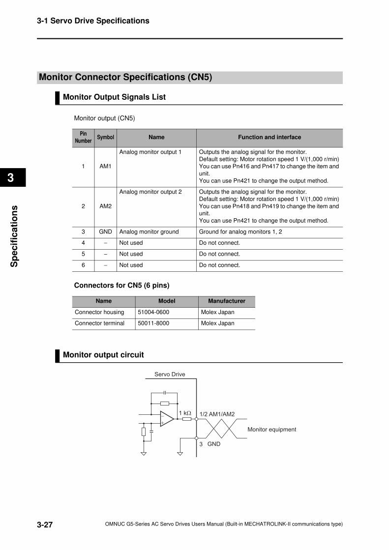
3-27
3-1 Servo Drive Specifications
OMNUC G5-Series AC Servo Drives Users Manual (Built-in MECHATROLINK-II communications type)
3
Sp
ecif
ica
tio
ns
Monitor Connector Specifications (CN5)
Monitor Output Signals List
Monitor output (CN5)
Connectors for CN5 (6 pins)
Monitor output circuit
Pin
NumberSymbol Name Function and interface
1 AM1
Analog monitor output 1 Outputs the analog signal for the monitor.
Default setting: Motor rotation speed 1 V/(1,000 r/min)
You can use Pn416 and Pn417 to change the item and
unit.
You can use Pn421 to change the output method.
2 AM2
Analog monitor output 2 Outputs the analog signal for the monitor.
Default setting: Motor rotation speed 1 V/(1,000 r/min)
You can use Pn418 and Pn419 to change the item and
unit.
You can use Pn421 to change the output method.
3 GND Analog monitor ground Ground for analog monitors 1, 2
4 − Not used Do not connect.
5 − Not used Do not connect.
6 − Not used Do not connect.
Name Model Manufacturer
Connector housing 51004-0600 Molex Japan
Connector terminal 50011-8000 Molex Japan
Servo Drive
Monitor equipment
3 GND
1/2 AM1/AM21 kΩ
+
−
3-28
3-1 Servo Drive Specifications
OMNUC G5-Series AC Servo Drives Users Manual (Built-in MECHATROLINK-II communications type)
3
Sp
ec
ifica
tion
s
USB Connector Specifications (CN7)
Through the USB connection with computer, operations such as parameter setting and
changing, monitoring of control status, checking error status and error history, and parameter
saving and loading can be performed.
Precautions for Correct Use
Use a commercially available USB cable that is shield, equipped with a ferrite core for noise
immunity, and supporting for USB2.0.
The Mini B type USB cable can be used.
Pin
numberSymbol Name Function and interface
1 VBUS
USB signal terminal
Use this function for computer communication.
2 D−
3 D+
4 − Reserved for manufacturer use Do not connect.
5 SENGND Signal ground Signal ground
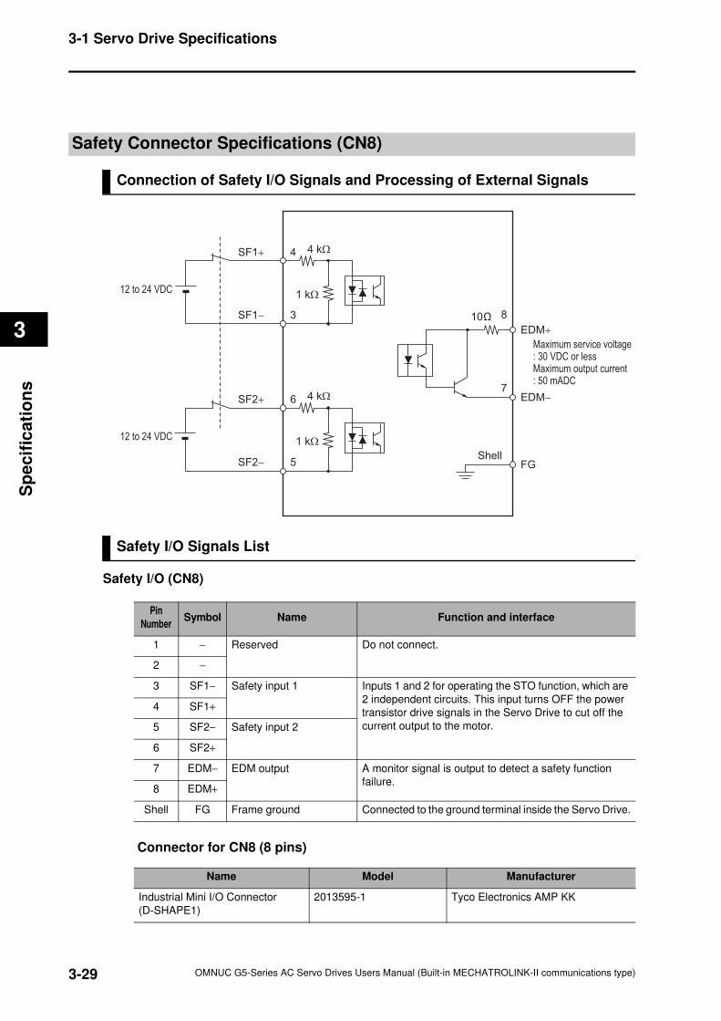
3-29
3-1 Servo Drive Specifications
OMNUC G5-Series AC Servo Drives Users Manual (Built-in MECHATROLINK-II communications type)
3
Sp
ecif
ica
tio
ns
Safety Connector Specifications (CN8)
Connection of Safety I/O Signals and Processing of External Signals
Safety I/O Signals List
Safety I/O (CN8)
Connector for CN8 (8 pins)
SF1+
12 to 24 VDC
SF1−
4
3
SF2+
12 to 24 VDC
SF2−
6
8
EDM+
EDM−
FG
7
5
10
4 kΩ
1 kΩ
4 kΩ
1 kΩ
Maximum service voltage: 30 VDC or less Maximum output current: 50 mADC
Shell
Pin
NumberSymbol Name Function and interface
1 − Reserved Do not connect.
2 −
3 SF1− Safety input 1 Inputs 1 and 2 for operating the STO function, which are
2 independent circuits. This input turns OFF the power
transistor drive signals in the Servo Drive to cut off the
current output to the motor.
4 SF1+
5 SF2− Safety input 2
6 SF2+
7 EDM− EDM output A monitor signal is output to detect a safety function
failure.8 EDM+
Shell FG Frame ground Connected to the ground terminal inside the Servo Drive.
Name Model Manufacturer
Industrial Mini I/O Connector
(D-SHAPE1)
2013595-1 Tyco Electronics AMP KK
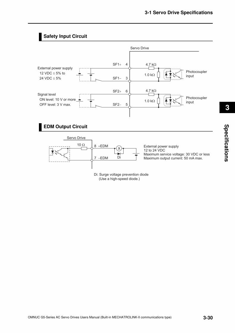
3-30
3-1 Servo Drive Specifications
OMNUC G5-Series AC Servo Drives Users Manual (Built-in MECHATROLINK-II communications type)
3
Sp
ec
ifica
tion
s
Safety Input Circuit
EDM Output Circuit
Servo Drive
External power supply
12 VDC ± 5% to
24 VDC ± 5%
Signal level
ON level: 10 V or more
OFF level: 3 V max.
4.7 kΩ
1.0 kΩ
SF1+ 4
SF1− 3
SF2+ 6
SF2− 5
Photocoupler
input
4.7 kΩ
1.0 kΩ
Photocoupler
input
External power supply 12 to 24 VDC Maximum service voltage: 30 VDC or less Maximum output current: 50 mA max.
Di: Surge voltage prevention diode
(Use a high-speed diode.)
7 −EDM
8 +EDM
Di
10 Ω
Servo Drive
X
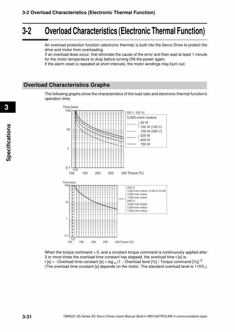
3-31
3-2 Overload Characteristics (Electronic Thermal Function)
OMNUC G5-Series AC Servo Drives Users Manual (Built-in MECHATROLINK-II communications type)
3
Sp
ecif
ica
tio
ns
3-2 Overload Characteristics (Electronic Thermal Function)
An overload protection function (electronic thermal) is built into the Servo Drive to protect the
drive and motor from overloading.
If an overload does occur, first eliminate the cause of the error and then wait at least 1 minute
for the motor temperature to drop before turning ON the power again.
If the alarm reset is repeated at short intervals, the motor windings may burn out.
Overload Characteristics Graphs
The following graphs show the characteristics of the load ratio and electronic thermal function's
operation time.
When the torque command = 0, and a constant torque command is continuously applied after
3 or more times the overload time constant has elapsed, the overload time t [s] is:
t [s] = −Overload time constant [s] × log e (1 − Overload level [%] / Torque command [%]) 2
(The overload time constant [s] depends on the motor. The standard overload level is 115%.)
100
0.1
1
10
100
150 200 250 300 Torque [%]115
Time [sec]
50 W
100 W (100 V)
100 W (200 V)
200 W
400 W
750 W
3,000-r/min motors
[100 V, 200 V]
100115
0.1
1
10
100
150 200 250 300 Torque [%]
Time [sec]
[200 V]
3,000-r/min motors 1.0 kW to 5.0 kW
2,000-r/min motors
1,000-r/min motors
[400 V]
3,000-r/min motors
2,000-r/min motors
1,000-r/min motors
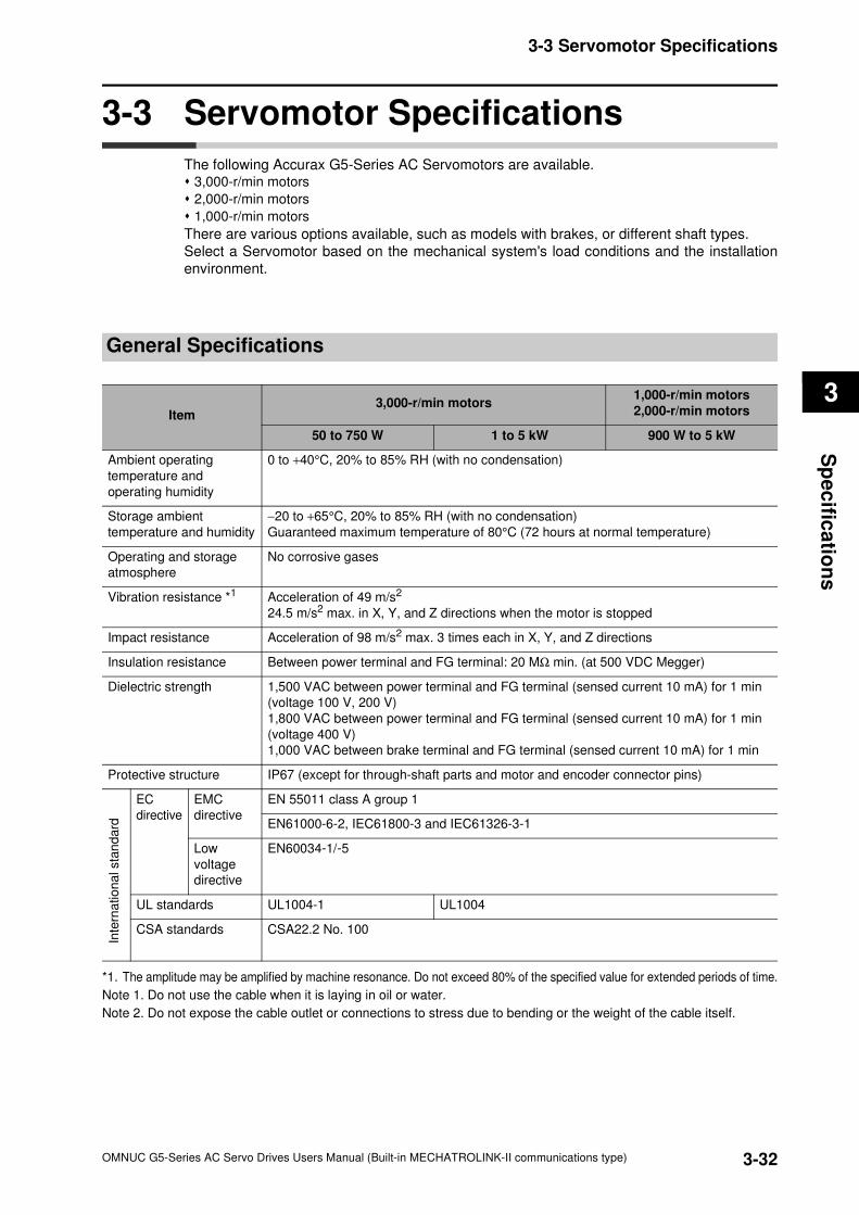
3-32
3-3 Servomotor Specifications
OMNUC G5-Series AC Servo Drives Users Manual (Built-in MECHATROLINK-II communications type)
3
Sp
ec
ifica
tion
s
3-3 Servomotor Specifications
The following Accurax G5-Series AC Servomotors are available. 3,000-r/min motors
2,000-r/min motors
1,000-r/min motors
There are various options available, such as models with brakes, or different shaft types.
Select a Servomotor based on the mechanical system's load conditions and the installation
environment.
General Specifications
*1. The amplitude may be amplified by machine resonance. Do not exceed 80% of the specified value for extended periods of time.
Note 1. Do not use the cable when it is laying in oil or water.
Note 2. Do not expose the cable outlet or connections to stress due to bending or the weight of the cable itself.
Item3,000-r/min motors
1,000-r/min motors
2,000-r/min motors
50 to 750 W 1 to 5 kW 900 W to 5 kW
Ambient operating
temperature and
operating humidity
0 to +40°C, 20% to 85% RH (with no condensation)
Storage ambient
temperature and humidity
−20 to +65°C, 20% to 85% RH (with no condensation)
Guaranteed maximum temperature of 80°C (72 hours at normal temperature)
Operating and storage
atmosphere
No corrosive gases
Vibration resistance *1 Acceleration of 49 m/s2
24.5 m/s2 max. in X, Y, and Z directions when the motor is stopped
Impact resistance Acceleration of 98 m/s2 max. 3 times each in X, Y, and Z directions
Insulation resistance Between power terminal and FG terminal: 20 MΩ min. (at 500 VDC Megger)
Dielectric strength 1,500 VAC between power terminal and FG terminal (sensed current 10 mA) for 1 min
(voltage 100 V, 200 V)
1,800 VAC between power terminal and FG terminal (sensed current 10 mA) for 1 min
(voltage 400 V)
1,000 VAC between brake terminal and FG terminal (sensed current 10 mA) for 1 min
Protective structure IP67 (except for through-shaft parts and motor and encoder connector pins)
EC
directive
EMC
directive
EN 55011 class A group 1
EN61000-6-2, IEC61800-3 and IEC61326-3-1
Low
voltage
directive
EN60034-1/-5
UL standards UL1004-1 UL1004
CSA standards CSA22.2 No. 100
Inte
rna
tio
na
l sta
nd
ard
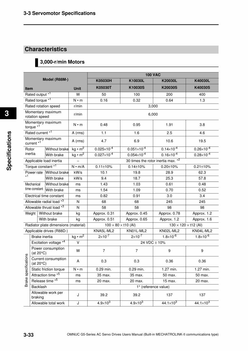
3-33
3-3 Servomotor Specifications
OMNUC G5-Series AC Servo Drives Users Manual (Built-in MECHATROLINK-II communications type)
3
Sp
ecif
ica
tio
ns
Characteristics
3,000-r/min Motors
Model (R88M-)
Item Unit
100 VAC
K05030H K10030L K20030L K40030L
K05030T K10030S K20030S K40030S
Rated output *1 W 50 100 200 400
Rated torque *1 N • m 0.16 0.32 0.64 1.3
Rated rotation speed r/min 3,000
Momentary maximum
rotation speedr/min 6,000
Momentary maximum
torque *1 N • m 0.48 0.95 1.91 3.8
Rated current *1 A (rms) 1.1 1.6 2.5 4.6
Momentary maximum
current *1 A (rms) 4.7 6.9 10.6 19.5
Rotor
inertia
Without brake kg • m2 0.025×10⁻⁴ 0.051×10⁻⁴ 0.14×10⁻⁴ 0.26×10⁻⁴
With brake kg • m2 0.027×10⁻⁴ 0.054×10⁻⁴ 0.16×10⁻⁴ 0.28×10⁻⁴
Applicable load inertia − 30 times the rotor inertia max. *2
Torque constant *1 N • m/A 0.11±10% 0.14±10% 0.20±10% 0.21±10%
Power rate
*1Without brake kW/s 10.1 19.8 28.9 62.3
With brake kW/s 9.4 18.7 25.3 57.8
Mechanical
time constant
Without brake ms 1.43 1.03 0.61 0.48
With brake ms 1.54 1.09 0.70 0.52
Electrical time constant ms 0.82 0.91 3.0 3.4
Allowable radial load *3 N 68 68 245 245
Allowable thrust load *3 N 58 58 98 98
Weight Without brake kg Approx. 0.31 Approx. 0.45 Approx. 0.78 Approx. 1.2
With brake kg Approx. 0.51 Approx. 0.65 Approx. 1.2 Approx. 1.6
Radiator plate dimensions (material) 100 × 80 × t10 (AI) 130 × 120 × t12 (AI)
Applicable drives (R88D-) KNA5L-ML2 KN01L-ML2 KN02L-ML2 KN04L-ML2
Bra
ke
sp
ecific
ation
s
Brake inertia kg • m2 2×10⁻⁷ 2×10⁻⁷ 1.8×10⁻⁶ 1.8×10⁻⁶
Excitation voltage *4 V 24 VDC ± 10%
Power consumption
(at 20°C)W 7 7 9 9
Current consumption
(at 20°C)A 0.3 0.3 0.36 0.36
Static friction torque N • m 0.29 min. 0.29 min. 1.27 min. 1.27 min.
Attraction time *5 ms 35 max. 35 max. 50 max. 50 max.
Release time *5 ms 20 max. 20 max. 15 max. 20 max.
Backlash 1° (reference value)
Allowable work per
brakingJ 39.2 39.2 137 137
Allowable total work J 4.9×10³ 4.9×10³ 44.1×10³ 44.1×10³
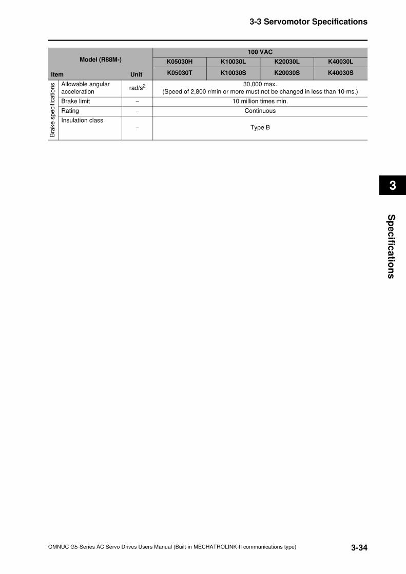
3-34
3-3 Servomotor Specifications
OMNUC G5-Series AC Servo Drives Users Manual (Built-in MECHATROLINK-II communications type)
3
Sp
ec
ifica
tion
s
Model (R88M-)
Item Unit
100 VAC
K05030H K10030L K20030L K40030L
K05030T K10030S K20030S K40030S
Bra
ke s
pe
cific
ation
s Allowable angular
accelerationrad/s2 30,000 max.
(Speed of 2,800 r/min or more must not be changed in less than 10 ms.)
Brake limit − 10 million times min.
Rating − Continuous
Insulation class− Type B
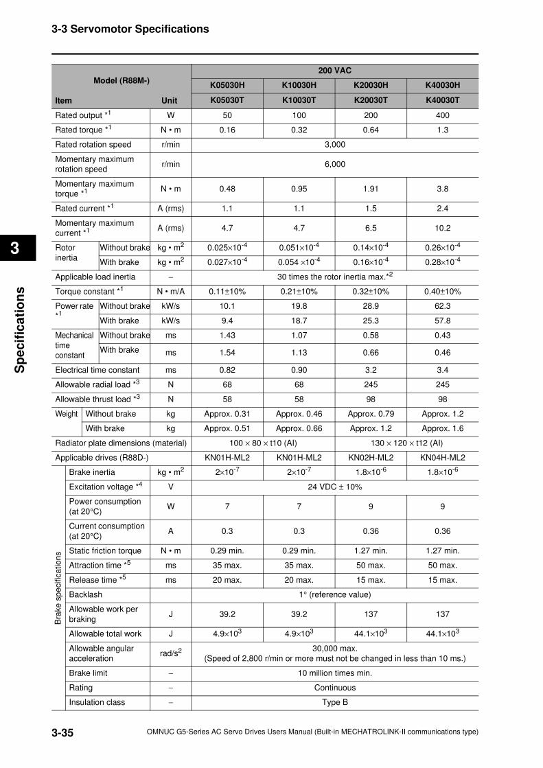
3-35
3-3 Servomotor Specifications
OMNUC G5-Series AC Servo Drives Users Manual (Built-in MECHATROLINK-II communications type)
3
Sp
ecif
ica
tio
ns
Model (R88M-)
Item Unit
200 VAC
K05030H K10030H K20030H K40030H
K05030T K10030T K20030T K40030T
Rated output *1 W 50 100 200 400
Rated torque *1 N • m 0.16 0.32 0.64 1.3
Rated rotation speed r/min 3,000
Momentary maximum
rotation speedr/min 6,000
Momentary maximum
torque *1 N • m 0.48 0.95 1.91 3.8
Rated current *1 A (rms) 1.1 1.1 1.5 2.4
Momentary maximum
current *1 A (rms) 4.7 4.7 6.5 10.2
Rotor
inertia
Without brake kg • m2 0.025×10⁻⁴ 0.051×10⁻⁴ 0.14×10⁻⁴ 0.26×10⁻⁴
With brake kg • m2 0.027×10⁻⁴ 0.054 ×10⁻⁴ 0.16×10⁻⁴ 0.28×10⁻⁴
Applicable load inertia − 30 times the rotor inertia max.*2
Torque constant *1 N • m/A 0.11±10% 0.21±10% 0.32±10% 0.40±10%
Power rate
*1Without brake kW/s 10.1 19.8 28.9 62.3
With brake kW/s 9.4 18.7 25.3 57.8
Mechanical
time
constant
Without brake ms 1.43 1.07 0.58 0.43
With brake ms 1.54 1.13 0.66 0.46
Electrical time constant ms 0.82 0.90 3.2 3.4
Allowable radial load *3 N 68 68 245 245
Allowable thrust load *3 N 58 58 98 98
Weight Without brake kg Approx. 0.31 Approx. 0.46 Approx. 0.79 Approx. 1.2
With brake kg Approx. 0.51 Approx. 0.66 Approx. 1.2 Approx. 1.6
Radiator plate dimensions (material) 100 × 80 × t10 (AI) 130 × 120 × t12 (AI)
Applicable drives (R88D-) KN01H-ML2 KN01H-ML2 KN02H-ML2 KN04H-ML2
Bra
ke
sp
ecific
ation
s
Brake inertia kg • m2 2×10⁻⁷ 2×10⁻⁷ 1.8×10⁻⁶ 1.8×10⁻⁶
Excitation voltage *4 V 24 VDC ± 10%
Power consumption
(at 20°C)W 7 7 9 9
Current consumption
(at 20°C)A 0.3 0.3 0.36 0.36
Static friction torque N • m 0.29 min. 0.29 min. 1.27 min. 1.27 min.
Attraction time *5 ms 35 max. 35 max. 50 max. 50 max.
Release time *5 ms 20 max. 20 max. 15 max. 15 max.
Backlash 1° (reference value)
Allowable work per
brakingJ 39.2 39.2 137 137
Allowable total work J 4.9×10³ 4.9×10³ 44.1×10³ 44.1×10³
Allowable angular
accelerationrad/s2 30,000 max.
(Speed of 2,800 r/min or more must not be changed in less than 10 ms.)
Brake limit − 10 million times min.
Rating − Continuous
Insulation class − Type B
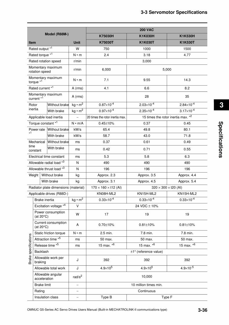
3-36
3-3 Servomotor Specifications
OMNUC G5-Series AC Servo Drives Users Manual (Built-in MECHATROLINK-II communications type)
3
Sp
ec
ifica
tion
s
Model (R88M-)
Item Unit
200 VAC
K75030H K1K030H K1K530H
K75030T K1K030T K1K530T
Rated output *1 W 750 1000 1500
Rated torque *1 N • m 2.4 3.18 4.77
Rated rotation speed r/min 3,000
Momentary maximum
rotation speedr/min 6,000 5,000
Momentary maximum
torque *1 N • m 7.1 9.55 14.3
Rated current *1 A (rms) 4.1 6.6 8.2
Momentary maximum
current *1 A (rms) 28 35
Rotor
inertia
Without brake kg • m2 0.87×10⁻⁴ 2.03×10⁻⁴ 2.84×10⁻⁴
With brake kg • m2 0.97×10⁻⁴ 2.35×10⁻⁴ 3.17×10⁻⁴
Applicable load inertia − 20 times the rotor inertia max. 15 times the rotor inertia max. *2
Torque constant *1 N • m/A 0.45±10% 0.37 0.45
Power rate
*1 Without brake kW/s 65.4 49.8 80.1
With brake kW/s 58.7 43.0 71.8
Mechanical
time
constant
Without brake ms 0.37 0.61 0.49
With brake ms 0.42 0.71 0.55
Electrical time constant ms 5.3 5.8 6.3
Allowable radial load *3 N 490 490 490
Allowable thrust load *3 N 196 196 196
Weight Without brake kg Approx. 2.3 Approx. 3.5 Approx. 4.4
With brake kg Approx. 3.1 Approx. 4.5 Approx. 5.4
Radiator plate dimensions (material) 170 × 160 × t12 (AI) 320 × 300 × t20 (AI)
Applicable drives (R88D-) KN08H-ML2 KN15H-ML2 KN15H-ML2
Bra
ke
sp
ecific
ation
s
Brake inertia kg • m2 0.33×10⁻⁴ 0.33×10⁻⁴ 0.33×10⁻⁴
Excitation voltage *4 V 24 VDC ± 10%
Power consumption
(at 20°C)W 17 19 19
Current consumption
(at 20°C)A 0.70±10% 0.81±10% 0.81±10%
Static friction torque N • m 2.5 min. 7.8 min. 7.8 min.
Attraction time *5 ms 50 max. 50 max. 50 max.
Release time *5 ms 15 max. *6 15 max. *6 15 max. *6
Backlash ±1° (reference value)
Allowable work per
brakingJ 392 392 392
Allowable total work J 4.9×10⁵ 4.9×10⁵ 4.9×10⁻⁵
Allowable angular
accelerationrad/s2 10,000
Brake limit − 10 million times min.
Rating − Continuous
Insulation class − Type B Type F

3-37
3-3 Servomotor Specifications
OMNUC G5-Series AC Servo Drives Users Manual (Built-in MECHATROLINK-II communications type)
3
Sp
ecif
ica
tio
ns
Model (R88M-)
Item Unit
AC200V
K2K030H K3K030H K4K030H K5K030H
K2K030T K3K030T K4K030T K5K030T
Rated output *1 W 2000 3000 4000 5000
Rated torque *1 N • m 6.37 9.55 12.7 15.9
Rated rotation speed r/min 3000
Momentary maximum
rotation speedr/min 5000 4500 4500
Momentary maximum
torque *1 N • m 19.1 28.6 38.2 47.7
Rated current *1 A (rms) 11.3 18.1 19.6 24.0
Momentary maximum
current *1 A (rms) 48 77 83 102
Rotor
inertia
Without brake kg • m2 3.68×10⁻⁴ 6.50×10⁻⁴ 12.9×10⁻⁴ 17.4×10⁻⁴
With brake kg • m2 4.01×10⁻⁴ 7.85×10⁻⁴ 14.2×10⁻⁴ 18.6×10⁻⁴
Applicable load inertia − 30 times the rotor inertia max.*2
Torque constant *1 N • m/A 0.44 0.41 0.49 0.49
Power rate
*1 Without brake kW/s 110 140 126 146
With brake kW/s 101 116 114 136
Mechanical
time
constant
Without brake ms 0.44 0.41 0.51 0.50
With brake ms 0.48 0.49 0.56 0.54
Electrical time constant ms 6.7 11 12 13
Allowable radial load *3 N 490 490 784 784
Allowable thrust load *3 N 196 196 343 343
Weight Without brake kg Approx. 5.3 Approx. 8.3 Approx. 11.0 Approx. 14.0
With brake kg Approx. 6.3 Approx. 9.4 Approx. 12.6 Approx. 16.0
Radiator plate dimensions (material) 380×350×t30 (A)
Applicable drives (R88D-) KN20H-ML2 KN30H-ML2 KN50H-ML2 KN50H-ML2
Bra
ke
sp
ecific
ation
s
Brake inertia kg • m2 0.33×10⁻⁴ 0.33×10⁻⁴ 1.35×10⁻⁴ 1.35×10⁻⁴
Excitation voltage *4 V 24 VDC±10%
Power consumption
(at 20°C)W 19 19 22 22
Current consumption
(at 20°C)A 0.81±10% 0.81±10% 0.90±10% 0.90±10%
Static friction torque N • m 7.8 min. 11.8 min. 16.1 min. 16.1 min.
Attraction time *5 ms 50 max. 80 max. 110 max. 110 max.
Release time *5 ms 15 max*6 15 max.*6 50 max.*7 50 max.*7
Backlash 1° (reference value)
Allowable work per
brakingJ 392 392 1470 1470
Allowable total work J 4.9×10⁶ 4.9×10⁶ 2.2×10⁶ 2.2×10⁶
Allowable angular
accelerationrad/s2 10000
Brake limit − 10 million times min.
Rating − Continuous
Insulation class − Type F
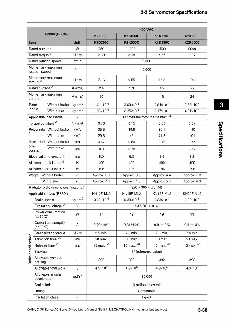
3-38
3-3 Servomotor Specifications
OMNUC G5-Series AC Servo Drives Users Manual (Built-in MECHATROLINK-II communications type)
3
Sp
ec
ifica
tion
s
Model (R88M-)
Item Unit
400 VAC
K75030F K1K030F K1K530F K2K030F
K75030C K1K030C K1K530C K2K030C
Rated output *1 W 750 1000 1500 2000
Rated torque *1 N • m 2.39 3.18 4.77 6.37
Rated rotation speed r/min 3,000
Momentary maximum
rotation speedr/min 5,000
Momentary maximum
torque *1 N • m 7.16 9.55 14.3 19.1
Rated current *1 A (rms) 2.4 3.3 4.2 5.7
Momentary maximum
current *1 A (rms) 10 14 18 24
Rotor
inertia
Without brake kg • m2 1.61×10⁻⁴ 2.03×10⁻⁴ 2.84×10⁻⁴ 3.68×10⁻⁴
With brake kg • m2 1.93×10⁻⁴ 2.35×10⁻⁴ 3.17×10⁻⁴ 4.01×10⁻⁴
Applicable load inertia − 30 times the rotor inertia max. *2
Torque constant *1 N • m/A 0.78 0.75 0.89 0.87
Power rate
*1Without brake kW/s 35.5 49.8 80.1 110
With brake kW/s 29.6 43 71.8 101
Mechanical
time
constant
Without brake ms 0.67 0.60 0.49 0.45
With brake ms 0.8 0.70 0.55 0.49
Electrical time constant ms 5.9 5.8 6.5 6.6
Allowable radial load *3 N 490 490 490 490
Allowable thrust load *3 N 196 196 196 196
Weight Without brake kg Approx. 3.1 Approx. 3.5 Approx. 4.4 Approx. 5.3
With brake kg Approx. 4.1 Approx. 4.5 Approx. 5.4 Approx. 6.3
Radiator plate dimensions (material) 320 × 300 × t20 (AI)
Applicable drives (R88D-) KN10F-ML2 KN15F-ML2 KN15F-ML2 KN20F-ML2
Bra
ke
sp
ecific
ation
s
Brake inertia kg • m2 0.33×10⁻⁴ 0.33×10⁻⁴ 0.33×10⁻⁴ 0.33×10⁻⁴
Excitation voltage *4 V 24 VDC ± 10%
Power consumption
(at 20°C)W 17 19 19 19
Current consumption
(at 20°C)A 0.70±10% 0.81±10% 0.81±10% 0.81±10%
Static friction torque N • m 2.5 min. 7.8 min. 7.8 min. 7.8 min.
Attraction time *5 ms 50 max. 50 max. 50 max. 50 max.
Release time *5 ms 15 max. *6 15 max. *6 15 max. *6 15 max. *6
Backlash 1° (reference value)
Allowable work per
brakingJ 392 392 392 392
Allowable total work J 4.9×10⁵ 4.9×10⁵ 4.9×10⁵ 4.9×10⁵
Allowable angular
accelerationrad/s2 10,000
Brake limit − 10 million times min.
Rating − Continuous
Insulation class − Type F
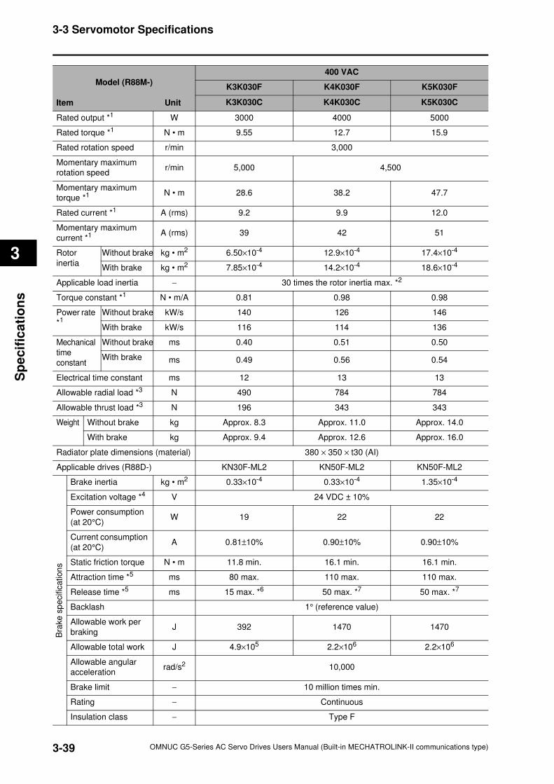
3-39
3-3 Servomotor Specifications
OMNUC G5-Series AC Servo Drives Users Manual (Built-in MECHATROLINK-II communications type)
3
Sp
ecif
ica
tio
ns
Model (R88M-)
Item Unit
400 VAC
K3K030F K4K030F K5K030F
K3K030C K4K030C K5K030C
Rated output *1 W 3000 4000 5000
Rated torque *1 N • m 9.55 12.7 15.9
Rated rotation speed r/min 3,000
Momentary maximum
rotation speedr/min 5,000 4,500
Momentary maximum
torque *1 N • m 28.6 38.2 47.7
Rated current *1 A (rms) 9.2 9.9 12.0
Momentary maximum
current *1 A (rms) 39 42 51
Rotor
inertia
Without brake kg • m2 6.50×10⁻⁴ 12.9×10⁻⁴ 17.4×10⁻⁴
With brake kg • m2 7.85×10⁻⁴ 14.2×10⁻⁴ 18.6×10⁻⁴
Applicable load inertia − 30 times the rotor inertia max. *2
Torque constant *1 N • m/A 0.81 0.98 0.98
Power rate
*1Without brake kW/s 140 126 146
With brake kW/s 116 114 136
Mechanical
time
constant
Without brake ms 0.40 0.51 0.50
With brake ms 0.49 0.56 0.54
Electrical time constant ms 12 13 13
Allowable radial load *3 N 490 784 784
Allowable thrust load *3 N 196 343 343
Weight Without brake kg Approx. 8.3 Approx. 11.0 Approx. 14.0
With brake kg Approx. 9.4 Approx. 12.6 Approx. 16.0
Radiator plate dimensions (material) 380 × 350 × t30 (AI)
Applicable drives (R88D-) KN30F-ML2 KN50F-ML2 KN50F-ML2
Bra
ke
sp
ecific
ation
s
Brake inertia kg • m2 0.33×10⁻⁴ 0.33×10⁻⁴ 1.35×10⁻⁴
Excitation voltage *4 V 24 VDC ± 10%
Power consumption
(at 20°C)W 19 22 22
Current consumption
(at 20°C)A 0.81±10% 0.90±10% 0.90±10%
Static friction torque N • m 11.8 min. 16.1 min. 16.1 min.
Attraction time *5 ms 80 max. 110 max. 110 max.
Release time *5 ms 15 max. *6 50 max. *7 50 max. *7
Backlash 1° (reference value)
Allowable work per
brakingJ 392 1470 1470
Allowable total work J 4.9×10⁵ 2.2×10⁶ 2.2×10⁶
Allowable angular
accelerationrad/s2 10,000
Brake limit − 10 million times min.
Rating − Continuous
Insulation class − Type F
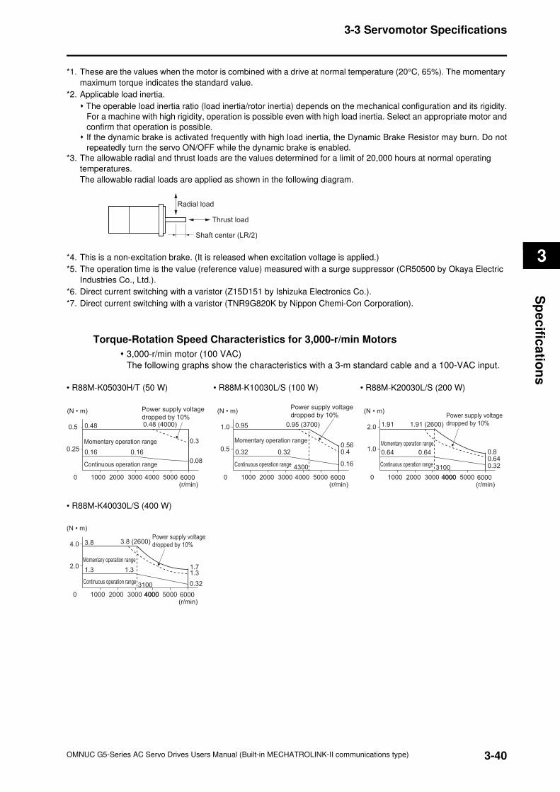
3-40
3-3 Servomotor Specifications
OMNUC G5-Series AC Servo Drives Users Manual (Built-in MECHATROLINK-II communications type)
3
Sp
ec
ifica
tion
s
*1. These are the values when the motor is combined with a drive at normal temperature (20°C, 65%). The momentary
maximum torque indicates the standard value.
*2. Applicable load inertia.
The operable load inertia ratio (load inertia/rotor inertia) depends on the mechanical configuration and its rigidity.
For a machine with high rigidity, operation is possible even with high load inertia. Select an appropriate motor and
confirm that operation is possible.
If the dynamic brake is activated frequently with high load inertia, the Dynamic Brake Resistor may burn. Do not
repeatedly turn the servo ON/OFF while the dynamic brake is enabled.
*3. The allowable radial and thrust loads are the values determined for a limit of 20,000 hours at normal operating
temperatures.
The allowable radial loads are applied as shown in the following diagram.
*4. This is a non-excitation brake. (It is released when excitation voltage is applied.)
*5. The operation time is the value (reference value) measured with a surge suppressor (CR50500 by Okaya Electric
Industries Co., Ltd.).
*6. Direct current switching with a varistor (Z15D151 by Ishizuka Electronics Co.).
*7. Direct current switching with a varistor (TNR9G820K by Nippon Chemi-Con Corporation).
Torque-Rotation Speed Characteristics for 3,000-r/min Motors
3,000-r/min motor (100 VAC)
The following graphs show the characteristics with a 3-m standard cable and a 100-VAC input.
• R88M-K05030H/T (50 W) • R88M-K10030L/S (100 W) • R88M-K20030L/S (200 W)
• R88M-K40030L/S (400 W)
Radial load
Thrust load
Shaft center (LR/2)
0.25
0 1000 2000 3000 4000 6000 (r/min)
5000
0.5 0.48
0.16 0.16
0.48 (4000)
0.3
(N • m)
Momentary operation range
Continuous operation range
Power supply voltage
dropped by 10%
0.08
0.5
0 1000 2000 3000 4000
4300
6000 (r/min)
5000
1.0 0.95 0.95 (3700)
0.560.40.32 0.32
(N • m)
Momentary operation range
Continuous operation range
Power supply voltage
dropped by 10%
0.16
1.0
0 1000 2000 3000 40004000 6000 (r/min)
5000
2.0 1.91
0.80.64
1.91 (2600)
0.64 0.64
(N • m)
Momentary operation range
Continuous operation range
Power supply voltage
dropped by 10%
0.32 3100
2.0
0 1000 2000 3000 40004000 6000 (r/min)
5000
4.0 3.8 3.8 (2600)
1.71.31.3 1.3
(N • m)
Momentary operation range
Continuous operation range
Power supply voltage
dropped by 10%
0.323100
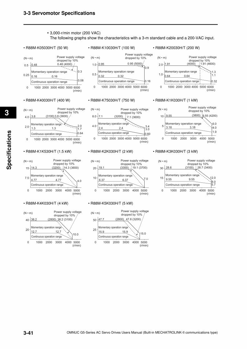
3-41
3-3 Servomotor Specifications
OMNUC G5-Series AC Servo Drives Users Manual (Built-in MECHATROLINK-II communications type)
3
Sp
ecif
ica
tio
ns
3,000-r/min motor (200 VAC)
The following graphs show the characteristics with a 3-m standard cable and a 200-VAC input.
• R88M-K05030H/T (50 W) • R88M-K10030H/T (100 W) • R88M-K20030H/T (200 W)
• R88M-K40030H/T (400 W) • R88M-K75030H/T (750 W) • R88M-K1K030H/T (1 kW)
• R88M-K1K530H/T (1.5 kW) • R88M-K2K030H/T (2 kW) • R88M-K3K030H/T (3 kW)
• R88M-K4K030H/T (4 kW) • R88M-K5K030H/T (5 kW)
0.5
0 1000 2000 3000 4000 6000 (r/min)
5000
1.0 0.95
0.32 0.32
0.95 (5000)
0.9
(N • m)
Momentary operation range
Continuous operation range
Power supply voltage
dropped by 10%
0.16
1.0
0 1000 2000 3000 4000 6000 (r/min)
5000
2.0 1.91
0.64 0.64
1.91 (4600)
1.3 1.1
(N • m)
Momentary operation range
Continuous operation range
Power supply voltage
dropped by 10%
0.32
(4000)
0.25
0 1000 2000 3000 4000 6000 (r/min)
5000
0.5 0.48
0.16 0.16
0.48 (4000)
0.3
(N • m)
Momentary operation range
Continuous operation range
Power supply voltage
dropped by 10%
0.08
2.0
0 1000 2000 3000 4000 6000 (r/min)
5000
4.0 3.8
1.3 1.3 1.72.0
3.8 (3600)
(N • m)
Momentary operation range
Continuous operation range
Power supply voltage
dropped by 10%
0.64
(3100)
4.0
0 1000 2000 3000
(3200)
4000 6000(r/min)
5000
8.0 7.1
3.43.0
7.1 (3600)
2.4 2.4
(N • m)
Momentary operation range
Continuous operation range
Power supply voltage
dropped by 10%
0.60
5
0 1000 2000 3000 4000 5000(r/min)
10 9.55 9.55 (4200)
3.18 3.18
(N • m)
Momentary operation range
Continuous operation range
Power supply voltage
dropped by 10%
6.0
4.0
1.9
(3800)
7.5
0 1000 2000 3000 4000 5000(r/min)
15 14.3 14.3 (3600)
4.77 4.77
(N • m)
Momentary operation range
Continuous operation range
Power supply voltage
dropped by 10%
4.0
(3200)
10
0 1000 2000 3000 4000 5000(r/min)
20 19.1 19.1 (3700)
6.37 6.37
(N • m)
Momentary operation range
Continuous operation range
Power supply voltage
dropped by 10%
7.0
(3300)
15
0 1000 2000 3000 4000 5000(r/min)
30 28.6 28.7 (3400)
9.55 9.55
(N • m)
Momentary operation range
Continuous operation range
Power supply voltage
dropped by 10%
12.0
5.78.0
(3100)
20
0 1000 2000 3000 4000 5000(r/min)
40 38.2
12.7 12.7
38.2 (3100)
(N • m)
Momentary operation range
Continuous operation range
Power supply voltage
dropped by 10%
10.0
(2800)
25
0 1000 2000 3000 4000 5000(r/min)
50 47.7 47.8 (3200)
15.9 15.9
(N • m)
Momentary operation range
Continuous operation range
Power supply voltage
dropped by 10%
15.0
(2800)
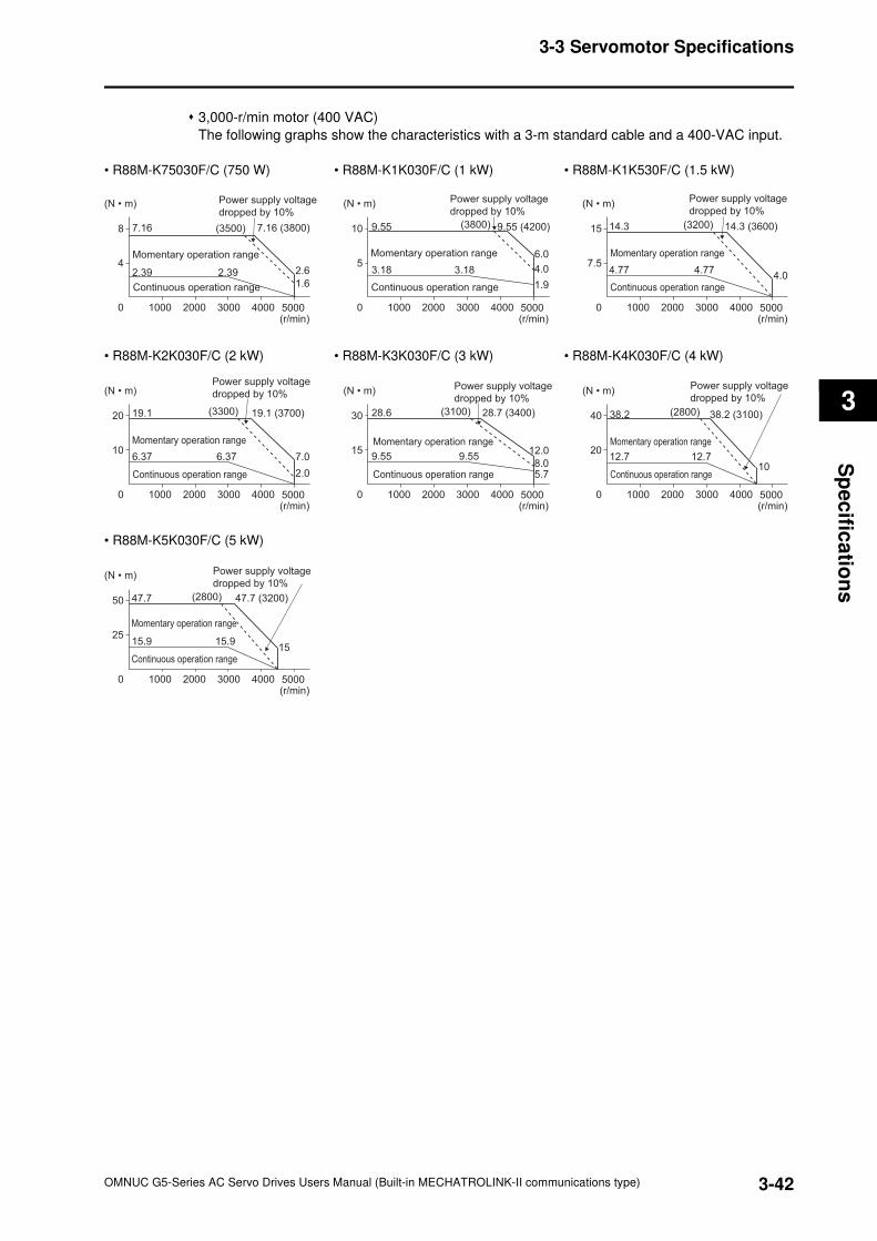
3-42
3-3 Servomotor Specifications
OMNUC G5-Series AC Servo Drives Users Manual (Built-in MECHATROLINK-II communications type)
3
Sp
ec
ifica
tion
s
3,000-r/min motor (400 VAC)
The following graphs show the characteristics with a 3-m standard cable and a 400-VAC input.
• R88M-K75030F/C (750 W) • R88M-K1K030F/C (1 kW) • R88M-K1K530F/C (1.5 kW)
• R88M-K2K030F/C (2 kW) • R88M-K3K030F/C (3 kW) • R88M-K4K030F/C (4 kW)
• R88M-K5K030F/C (5 kW)
4
0 1000 2000 3000 4000 5000 (r/min)
8 7.16 7.16 (3800)
2.39 2.39
(N • m)
Momentary operation range
Continuous operation range
Power supply voltage
dropped by 10%
2.6
1.6
(3500)
5
0 1000 2000 3000 4000 5000 (r/min)
10 9.55 9.55 (4200)
3.18 3.18
(N • m)
Momentary operation range
Continuous operation range
Power supply voltage
dropped by 10%
1.9
6.0
4.0
(3800)
7.5
0 1000 2000 3000 4000 5000 (r/min)
15 14.3 14.3 (3600)
4.77 4.77
(N • m)
Momentary operation range
Continuous operation range
Power supply voltage
dropped by 10%
4.0
(3200)
10
0 1000 2000 3000 4000 5000 (r/min)
20 19.1
6.37 6.37
19.1 (3700)
(N • m)
Momentary operation range
Continuous operation range
Power supply voltage
dropped by 10%
7.0
2.0
(3300)
Continuous operation range
15
0 1000 2000 3000 4000 5000 (r/min)
30 28.6 28.7 (3400)
9.55 9.55
(N • m)
Momentary operation range
Power supply voltage
dropped by 10%
5.7
12.0
8.0
(3100)
20
0 1000 2000 3000 4000 5000 (r/min)
40 38.2
12.7 12.7
38.2 (3100)
(N • m)
Momentary operation range
Continuous operation range
Power supply voltage
dropped by 10%
10
(2800)
25
0 1000 2000 3000 4000 5000 (r/min)
50 47.7 47.7 (3200)
15.9 15.9
(N • m)
Momentary operation range
Continuous operation range
Power supply voltage
dropped by 10%
15
(2800)
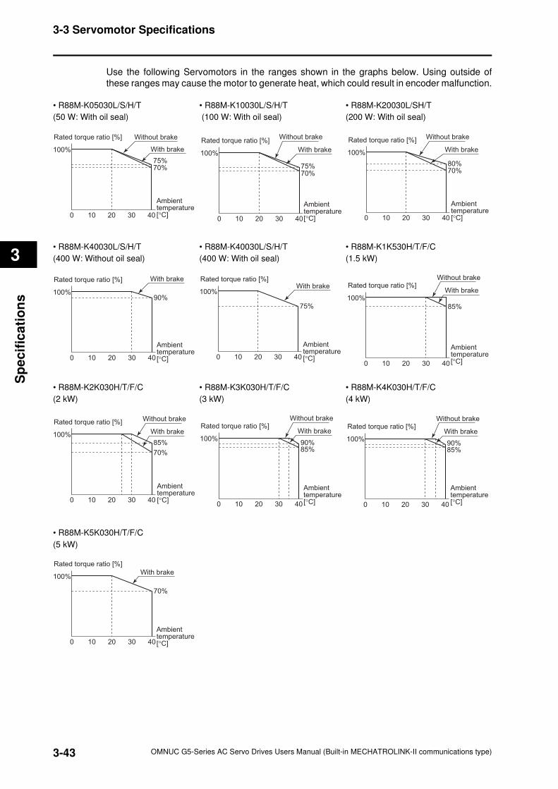
3-43
3-3 Servomotor Specifications
OMNUC G5-Series AC Servo Drives Users Manual (Built-in MECHATROLINK-II communications type)
3
Sp
ecif
ica
tio
ns
Use the following Servomotors in the ranges shown in the graphs below. Using outside of
these ranges may cause the motor to generate heat, which could result in encoder malfunction.
• R88M-K05030L/S/H/T • R88M-K10030L/S/H/T • R88M-K20030L/SH/T
(50 W: With oil seal) (100 W: With oil seal) (200 W: With oil seal)
• R88M-K40030L/S/H/T • R88M-K40030L/S/H/T • R88M-K1K530H/T/F/C
(400 W: Without oil seal) (400 W: With oil seal) (1.5 kW)
• R88M-K2K030H/T/F/C • R88M-K3K030H/T/F/C • R88M-K4K030H/T/F/C
(2 kW) (3 kW) (4 kW)
• R88M-K5K030H/T/F/C
(5 kW)
Rated torque ratio [%]
Ambient temperature [°C]
100%
75%70%
100 20 30 40
Without brake
With brake
Rated torque ratio [%]
100%
75%70%
100 20 30 40
Without brake
With brake
Ambient temperature [°C]
Rated torque ratio [%]
100%
80%70%
100 20 30 40
Without brake
With brake
Ambient temperature [°C]
Rated torque ratio [%]
100%90%
100 20 30 40
With brake
Ambient temperature [°C]
Rated torque ratio [%]
100%
75%
100 20 30 40
With brake
Ambient temperature [°C]
Rated torque ratio [%]
100%
85%
100 20 30 40
Without brake
With brake
Ambient temperature [°C]
Rated torque ratio [%]
100%85%
70%
100 20 30 40
Without brake
With brake
Ambient temperature [°C]
Rated torque ratio [%]
100%
85%90%
100 20 30 40
Without brake
With brake
Ambient temperature [°C]
Rated torque ratio [%]
100%
85%90%
100 20 30 40
Without brake
With brake
Ambient temperature [°C]
Rated torque ratio [%]
100%
70%
100 20 30 40
With brake
Ambient temperature [°C]
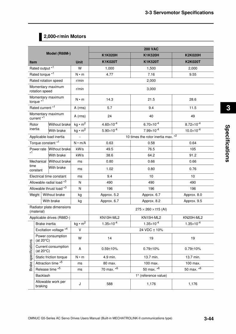
3-44
3-3 Servomotor Specifications
OMNUC G5-Series AC Servo Drives Users Manual (Built-in MECHATROLINK-II communications type)
3
Sp
ec
ifica
tion
s
2,000-r/min Motors
Model (R88M-)
Item Unit
200 VAC
K1K020H K1K520H K2K020H
K1K020T K1K520T K2K020T
Rated output *1 W 1,000 1,500 2,000
Rated torque *1 N • m 4.77 7.16 9.55
Rated rotation speed r/min 2,000
Momentary maximum
rotation speedr/min 3,000
Momentary maximum
torque *1 N • m 14.3 21.5 28.6
Rated current *1 A (rms) 5.7 9.4 11.5
Momentary maximum
current *1 A (rms) 24 40 49
Rotor
inertia
Without brake kg • m2 4.60×10⁻⁴ 6.70×10⁻⁴ 8.72×10⁻⁴
With brake kg • m2 5.90×10⁻⁴ 7.99×10⁻⁴ 10.0×10⁻⁴
Applicable load inertia − 10 times the rotor inertia max. *2
Torque constant *1 N • m/A 0.63 0.58 0.64
Power rate
*1 Without brake kW/s 49.5 76.5 105
With brake kW/s 38.6 64.2 91.2
Mechanical
time
constant
Without brake ms 0.80 0.66 0.66
With brake ms 1.02 0.80 0.76
Electrical time constant ms 9.4 10 10
Allowable radial load *3 N 490 490 490
Allowable thrust load *3 N 196 196 196
Weight Without brake kg Approx. 5.2 Approx. 6.7 Approx. 8.0
With brake kg Approx. 6.7 Approx. 8.2 Approx. 9.5
Radiator plate dimensions
(material)275 × 260 × t15 (AI)
Applicable drives (R88D-) KN10H-ML2 KN15H-ML2 KN20H-ML2
Bra
ke s
pe
cific
atio
ns
Brake inertia kg • m2 1.35×10⁻⁴ 1.35×10⁻⁴ 1.35×10⁻⁴
Excitation voltage *4 V 24 VDC ± 10%
Power consumption
(at 20°C)W 14 19 19
Current consumption
(at 20°C)A 0.59±10% 0.79±10% 0.79±10%
Static friction torque N • m 4.9 min. 13.7 min. 13.7 min.
Attraction time *5 ms 80 max. 100 max. 100 max.
Release time *5 ms 70 max. *6 50 max. *6 50 max. *6
Backlash 1° (reference value)
Allowable work per
brakingJ 588 1,176 1,176
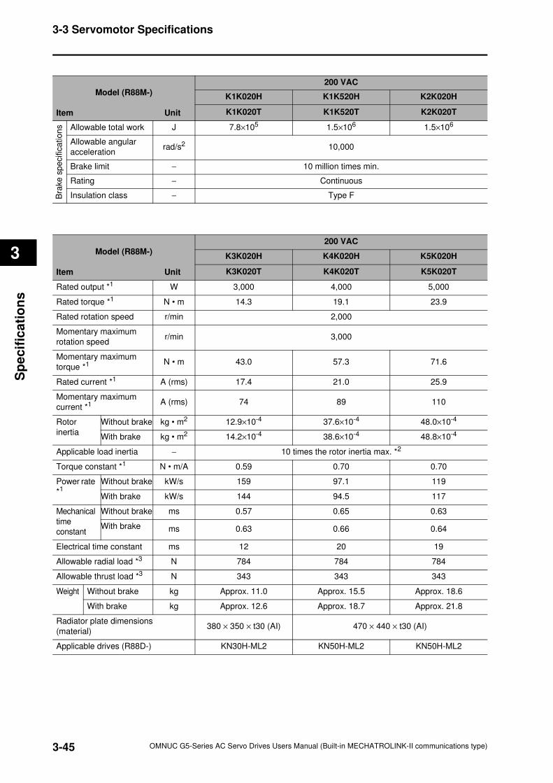
3-45
3-3 Servomotor Specifications
OMNUC G5-Series AC Servo Drives Users Manual (Built-in MECHATROLINK-II communications type)
3
Sp
ecif
ica
tio
ns
Model (R88M-)
Item Unit
200 VAC
K1K020H K1K520H K2K020H
K1K020T K1K520T K2K020T
Bra
ke
sp
ecific
ation
s Allowable total work J 7.8×10⁵ 1.5×10⁶ 1.5×10⁶
Allowable angular
accelerationrad/s2 10,000
Brake limit − 10 million times min.
Rating − Continuous
Insulation class − Type F
Model (R88M-)
Item Unit
200 VAC
K3K020H K4K020H K5K020H
K3K020T K4K020T K5K020T
Rated output *1 W 3,000 4,000 5,000
Rated torque *1 N • m 14.3 19.1 23.9
Rated rotation speed r/min 2,000
Momentary maximum
rotation speedr/min 3,000
Momentary maximum
torque *1 N • m 43.0 57.3 71.6
Rated current *1 A (rms) 17.4 21.0 25.9
Momentary maximum
current *1 A (rms) 74 89 110
Rotor
inertia
Without brake kg • m2 12.9×10⁻⁴ 37.6×10⁻⁴ 48.0×10⁻⁴
With brake kg • m2 14.2×10⁻⁴ 38.6×10⁻⁴ 48.8×10⁻⁴
Applicable load inertia − 10 times the rotor inertia max. *2
Torque constant *1 N • m/A 0.59 0.70 0.70
Power rate
*1 Without brake kW/s 159 97.1 119
With brake kW/s 144 94.5 117
Mechanical
time
constant
Without brake ms 0.57 0.65 0.63
With brake ms 0.63 0.66 0.64
Electrical time constant ms 12 20 19
Allowable radial load *3 N 784 784 784
Allowable thrust load *3 N 343 343 343
Weight Without brake kg Approx. 11.0 Approx. 15.5 Approx. 18.6
With brake kg Approx. 12.6 Approx. 18.7 Approx. 21.8
Radiator plate dimensions
(material)380 × 350 × t30 (AI) 470 × 440 × t30 (AI)
Applicable drives (R88D-) KN30H-ML2 KN50H-ML2 KN50H-ML2
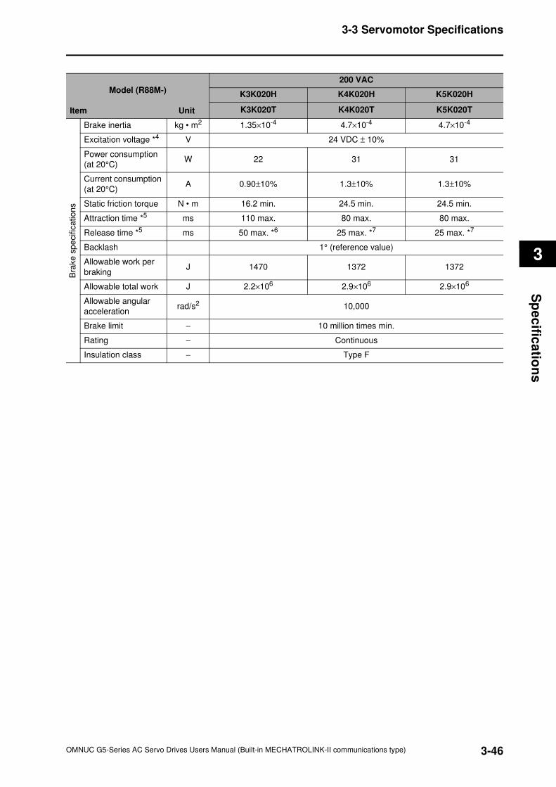
3-46
3-3 Servomotor Specifications
OMNUC G5-Series AC Servo Drives Users Manual (Built-in MECHATROLINK-II communications type)
3
Sp
ec
ifica
tion
s
Model (R88M-)
Item Unit
200 VAC
K3K020H K4K020H K5K020H
K3K020T K4K020T K5K020T
Bra
ke s
pe
cific
ation
s
Brake inertia kg • m2 1.35×10⁻⁴ 4.7×10⁻⁴ 4.7×10⁻⁴
Excitation voltage *4 V 24 VDC ± 10%
Power consumption
(at 20°C)W 22 31 31
Current consumption
(at 20°C)A 0.90±10% 1.3±10% 1.3±10%
Static friction torque N • m 16.2 min. 24.5 min. 24.5 min.
Attraction time *5 ms 110 max. 80 max. 80 max.
Release time *5 ms 50 max. *6 25 max. *7 25 max. *7
Backlash 1° (reference value)
Allowable work per
brakingJ 1470 1372 1372
Allowable total work J 2.2×10⁶ 2.9×10⁶ 2.9×10⁶
Allowable angular
accelerationrad/s2 10,000
Brake limit − 10 million times min.
Rating − Continuous
Insulation class − Type F
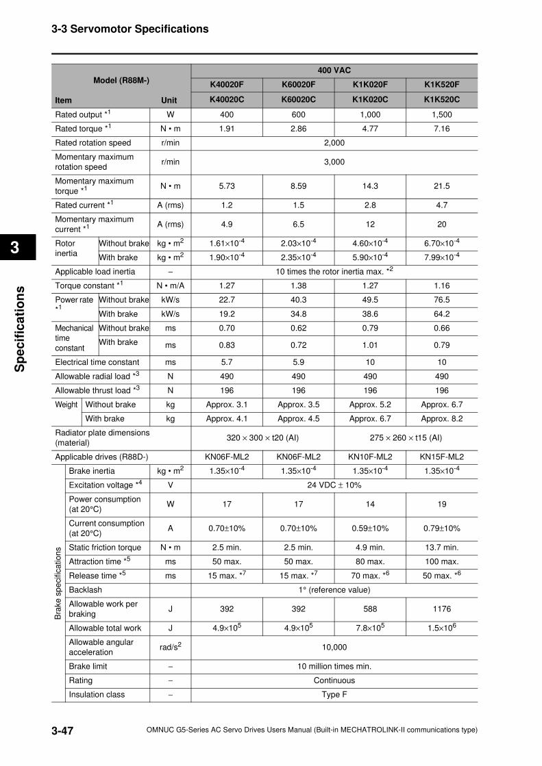
3-47
3-3 Servomotor Specifications
OMNUC G5-Series AC Servo Drives Users Manual (Built-in MECHATROLINK-II communications type)
3
Sp
ecif
ica
tio
ns
Model (R88M-)
Item Unit
400 VAC
K40020F K60020F K1K020F K1K520F
K40020C K60020C K1K020C K1K520C
Rated output *1 W 400 600 1,000 1,500
Rated torque *1 N • m 1.91 2.86 4.77 7.16
Rated rotation speed r/min 2,000
Momentary maximum
rotation speedr/min 3,000
Momentary maximum
torque *1 N • m 5.73 8.59 14.3 21.5
Rated current *1 A (rms) 1.2 1.5 2.8 4.7
Momentary maximum
current *1 A (rms) 4.9 6.5 12 20
Rotor
inertia
Without brake kg • m2 1.61×10⁻⁴ 2.03×10⁻⁴ 4.60×10⁻⁴ 6.70×10⁻⁴
With brake kg • m2 1.90×10⁻⁴ 2.35×10⁻⁴ 5.90×10⁻⁴ 7.99×10⁻⁴
Applicable load inertia − 10 times the rotor inertia max. *2
Torque constant *1 N • m/A 1.27 1.38 1.27 1.16
Power rate
*1 Without brake kW/s 22.7 40.3 49.5 76.5
With brake kW/s 19.2 34.8 38.6 64.2
Mechanical
time
constant
Without brake ms 0.70 0.62 0.79 0.66
With brake ms 0.83 0.72 1.01 0.79
Electrical time constant ms 5.7 5.9 10 10
Allowable radial load *3 N 490 490 490 490
Allowable thrust load *3 N 196 196 196 196
Weight Without brake kg Approx. 3.1 Approx. 3.5 Approx. 5.2 Approx. 6.7
With brake kg Approx. 4.1 Approx. 4.5 Approx. 6.7 Approx. 8.2
Radiator plate dimensions
(material)320 × 300 × t20 (AI) 275 × 260 × t15 (AI)
Applicable drives (R88D-) KN06F-ML2 KN06F-ML2 KN10F-ML2 KN15F-ML2
Bra
ke s
pe
cific
ation
s
Brake inertia kg • m2 1.35×10⁻⁴ 1.35×10⁻⁴ 1.35×10⁻⁴ 1.35×10⁻⁴
Excitation voltage *4 V 24 VDC ± 10%
Power consumption
(at 20°C)W 17 17 14 19
Current consumption
(at 20°C)A 0.70±10% 0.70±10% 0.59±10% 0.79±10%
Static friction torque N • m 2.5 min. 2.5 min. 4.9 min. 13.7 min.
Attraction time *5 ms 50 max. 50 max. 80 max. 100 max.
Release time *5 ms 15 max. *7 15 max. *7 70 max. *6 50 max. *6
Backlash 1° (reference value)
Allowable work per
brakingJ 392 392 588 1176
Allowable total work J 4.9×10⁵ 4.9×10⁵ 7.8×10⁵ 1.5×10⁶
Allowable angular
accelerationrad/s2 10,000
Brake limit − 10 million times min.
Rating − Continuous
Insulation class − Type F
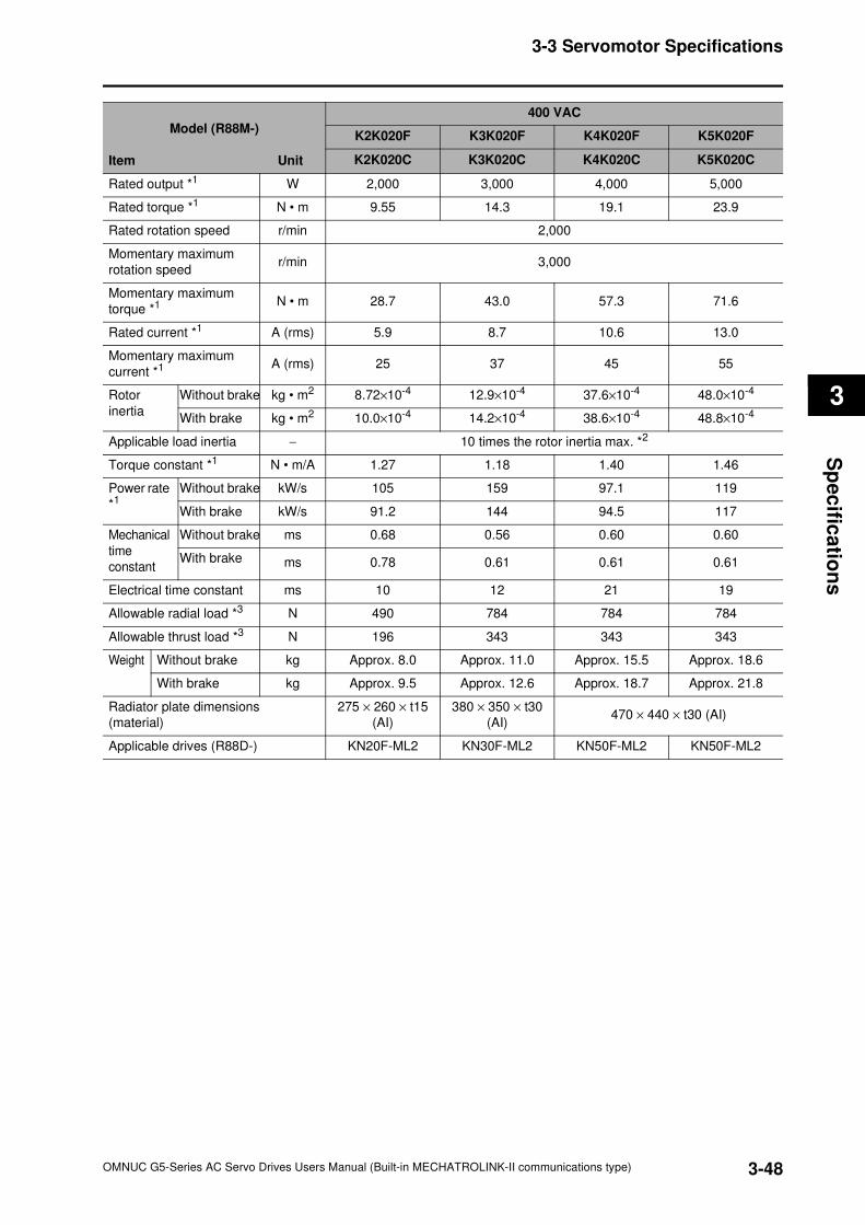
3-48
3-3 Servomotor Specifications
OMNUC G5-Series AC Servo Drives Users Manual (Built-in MECHATROLINK-II communications type)
3
Sp
ec
ifica
tion
s
Model (R88M-)
Item Unit
400 VAC
K2K020F K3K020F K4K020F K5K020F
K2K020C K3K020C K4K020C K5K020C
Rated output *1 W 2,000 3,000 4,000 5,000
Rated torque *1 N • m 9.55 14.3 19.1 23.9
Rated rotation speed r/min 2,000
Momentary maximum
rotation speedr/min 3,000
Momentary maximum
torque *1 N • m 28.7 43.0 57.3 71.6
Rated current *1 A (rms) 5.9 8.7 10.6 13.0
Momentary maximum
current *1 A (rms) 25 37 45 55
Rotor
inertia
Without brake kg • m2 8.72×10⁻⁴ 12.9×10⁻⁴ 37.6×10⁻⁴ 48.0×10⁻⁴
With brake kg • m2 10.0×10⁻⁴ 14.2×10⁻⁴ 38.6×10⁻⁴ 48.8×10⁻⁴
Applicable load inertia − 10 times the rotor inertia max. *2
Torque constant *1 N • m/A 1.27 1.18 1.40 1.46
Power rate
*1 Without brake kW/s 105 159 97.1 119
With brake kW/s 91.2 144 94.5 117
Mechanical
time
constant
Without brake ms 0.68 0.56 0.60 0.60
With brake ms 0.78 0.61 0.61 0.61
Electrical time constant ms 10 12 21 19
Allowable radial load *3 N 490 784 784 784
Allowable thrust load *3 N 196 343 343 343
Weight Without brake kg Approx. 8.0 Approx. 11.0 Approx. 15.5 Approx. 18.6
With brake kg Approx. 9.5 Approx. 12.6 Approx. 18.7 Approx. 21.8
Radiator plate dimensions
(material)
275 × 260 × t15
(AI)
380 × 350 × t30
(AI)470 × 440 × t30 (AI)
Applicable drives (R88D-) KN20F-ML2 KN30F-ML2 KN50F-ML2 KN50F-ML2
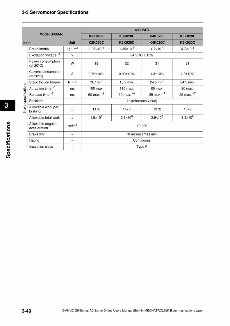
3-49
3-3 Servomotor Specifications
OMNUC G5-Series AC Servo Drives Users Manual (Built-in MECHATROLINK-II communications type)
3
Sp
ecif
ica
tio
ns
Bra
ke
spe
cific
atio
ns
Brake inertia kg • m2 1.35×10⁻⁴ 1.35×10⁻⁴ 4.7×10⁻⁴ 4.7×10⁻⁴
Excitation voltage *4 V 24 VDC ± 10%
Power consumption
(at 20°C)W 19 22 31 31
Current consumption
(at 20°C)A 0.79±10% 0.90±10% 1.3±10% 1.3±10%
Static friction torque N • m 13.7 min. 16.2 min. 24.5 min. 24.5 min.
Attraction time *5 ms 100 max. 110 max. 80 max. 80 max.
Release time *5 ms 50 max. *6 50 max. *6 25 max. *7 25 max. *7
Backlash 1° (reference value)
Allowable work per
brakingJ 1176 1470 1372 1372
Allowable total work J 1.5×10⁶ 2.2×10⁶ 2.9×10⁶ 2.9×10⁶
Allowable angular
accelerationrad/s2 10,000
Brake limit − 10 million times min.
Rating − Continuous
Insulation class − Type F
Model (R88M-)
Item Unit
400 VAC
K2K020F K3K020F K4K020F K5K020F
K2K020C K3K020C K4K020C K5K020C
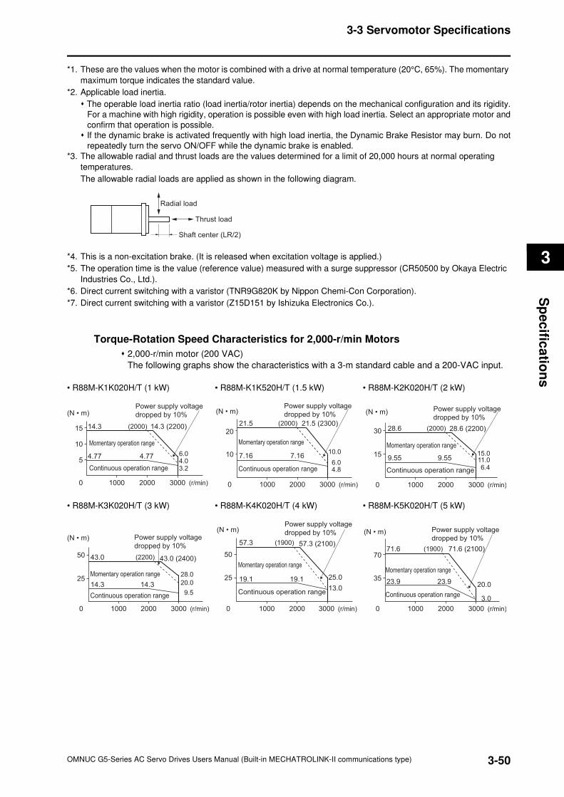
3-50
3-3 Servomotor Specifications
OMNUC G5-Series AC Servo Drives Users Manual (Built-in MECHATROLINK-II communications type)
3
Sp
ec
ifica
tion
s
*1. These are the values when the motor is combined with a drive at normal temperature (20°C, 65%). The momentary
maximum torque indicates the standard value.
*2. Applicable load inertia.
The operable load inertia ratio (load inertia/rotor inertia) depends on the mechanical configuration and its rigidity.
For a machine with high rigidity, operation is possible even with high load inertia. Select an appropriate motor and
confirm that operation is possible.
If the dynamic brake is activated frequently with high load inertia, the Dynamic Brake Resistor may burn. Do not
repeatedly turn the servo ON/OFF while the dynamic brake is enabled.
*3. The allowable radial and thrust loads are the values determined for a limit of 20,000 hours at normal operating
temperatures.
The allowable radial loads are applied as shown in the following diagram.
*4. This is a non-excitation brake. (It is released when excitation voltage is applied.)
*5. The operation time is the value (reference value) measured with a surge suppressor (CR50500 by Okaya Electric
Industries Co., Ltd.).
*6. Direct current switching with a varistor (TNR9G820K by Nippon Chemi-Con Corporation).
*7. Direct current switching with a varistor (Z15D151 by Ishizuka Electronics Co.).
Torque-Rotation Speed Characteristics for 2,000-r/min Motors
2,000-r/min motor (200 VAC)
The following graphs show the characteristics with a 3-m standard cable and a 200-VAC input.
• R88M-K1K020H/T (1 kW) • R88M-K1K520H/T (1.5 kW) • R88M-K2K020H/T (2 kW)
• R88M-K3K020H/T (3 kW) • R88M-K4K020H/T (4 kW) • R88M-K5K020H/T (5 kW)
Radial load
Thrust load
Shaft center (LR/2)
(N • m)
0 1000 2000
5
10
15 14.3
4.77 4.77
14.3 (2200)
Momentary operation range
Continuous operation range
3000 (r/min)
Power supply voltage
dropped by 10%
6.04.0
(2000)
3.2
(N • m)
10
0
2021.5
7.16 7.16
21.5 (2300)
1000 2000
Momentary operation range
Continuous operation range
3000 (r/min)
Power supply voltage
dropped by 10%
10.0
6.0
(2000)
4.8
(N • m)
15
0
30 28.6
9.55 9.55
28.6 (2200)
1000 2000 3000 (r/min)
Momentary operation range
Continuous operation range
Power supply voltage
dropped by 10%
15.011.0
(2000)
6.4
(N • m)
25
0
50 43.0
14.3 14.3
43.0 (2400)
1000 2000
Momentary operation range
Continuous operation range
3000 (r/min)
Power supply voltage
dropped by 10%
28.0
(2200)
20.0
9.5
Momentary operation range
Continuous operation range
(N • m)
25
0
50
57.3
19.1 19.1
57.3 (2100)
1000 2000 3000 (r/min)
Power supply voltage
dropped by 10%
25.0
13.0
(1900)
35
0
7071.6 71.6 (2100)
23.9 23.9
1000 2000 3000 (r/min)
20.0
3.0
(1900)
Power supply voltage
dropped by 10%
Continuous operation range
Momentary operation range
(N • m)
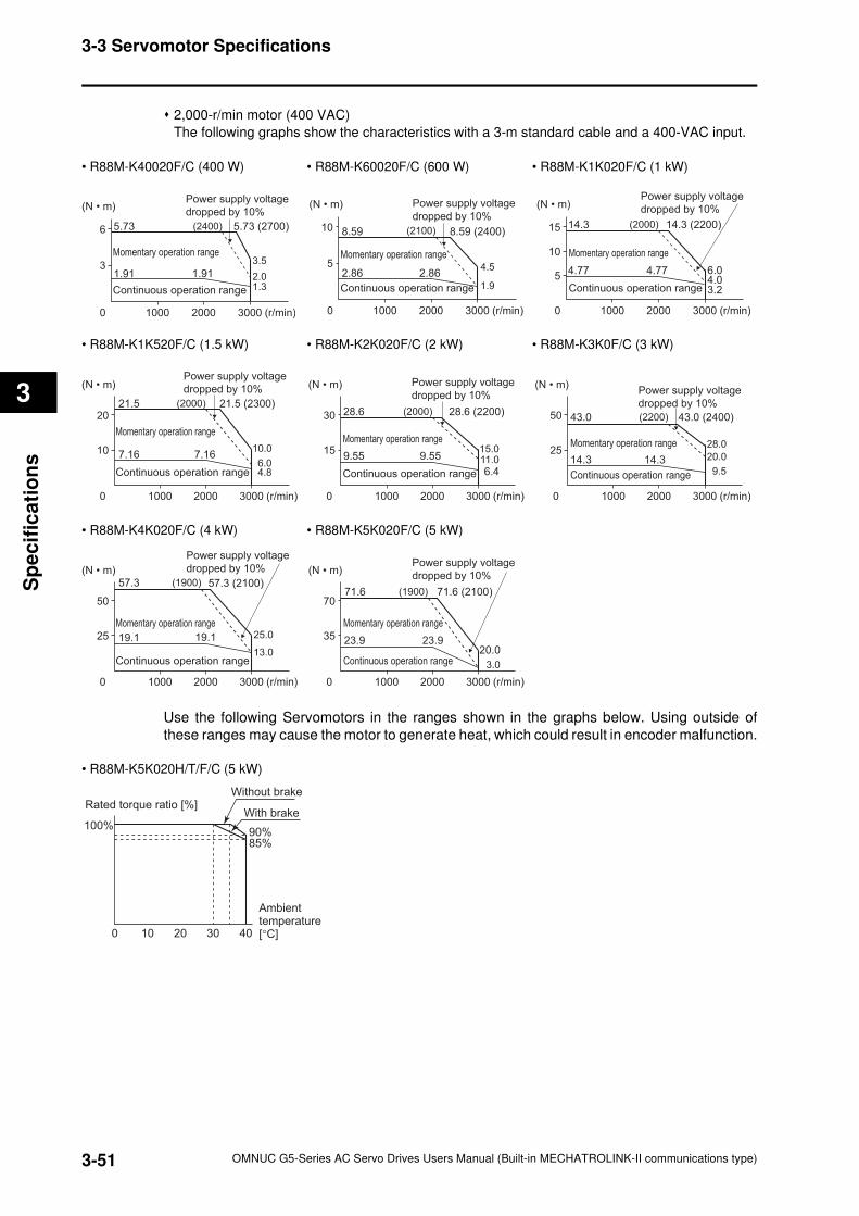
3-51
3-3 Servomotor Specifications
OMNUC G5-Series AC Servo Drives Users Manual (Built-in MECHATROLINK-II communications type)
3
Sp
ecif
ica
tio
ns
2,000-r/min motor (400 VAC)
The following graphs show the characteristics with a 3-m standard cable and a 400-VAC input.
• R88M-K40020F/C (400 W) • R88M-K60020F/C (600 W) • R88M-K1K020F/C (1 kW)
• R88M-K1K520F/C (1.5 kW) • R88M-K2K020F/C (2 kW) • R88M-K3K0F/C (3 kW)
• R88M-K4K020F/C (4 kW) • R88M-K5K020F/C (5 kW)
Use the following Servomotors in the ranges shown in the graphs below. Using outside of
these ranges may cause the motor to generate heat, which could result in encoder malfunction.
• R88M-K5K020H/T/F/C (5 kW)
0 1000 2000
3
6 5.73
1.91 1.91
5.73 (2700)
3000 (r/min)
3.5
(2400)
2.01.3
Power supply voltage
dropped by 10%
Continuous operation range
Momentary operation range
(N • m)
0 1000 2000
5
10 8.59
2.86 2.86
8.59 (2400)
3000 (r/min)
4.5
(2100)
1.9
Power supply voltage
dropped by 10%
Continuous operation range
Momentary operation range
(N • m)
0 1000 2000
5
10
15 14.3
4.77 4.77
14.3 (2200)
3000 (r/min)
6.04.03.2
(2000)
Power supply voltage
dropped by 10%
Continuous operation range
Momentary operation range
(N • m)
10
0
2021.5
7.16 7.16
21.5 (2300)
1000 2000 3000 (r/min)
10.0
6.04.8
(2000)
Power supply voltage
dropped by 10%
Continuous operation range
Momentary operation range
(N • m)
15
0
30 28.6
9.55 9.55
28.6 (2200)
1000 2000 3000 (r/min)
15.011.0
6.4
(2000)
Power supply voltage
dropped by 10%
Continuous operation range
Momentary operation range
(N • m)
25
0
50 43.0
14.3 14.3
43.0 (2400)
1000 2000 3000 (r/min)
28.0
20.0
9.5
(2200)
Power supply voltage
dropped by 10%
Continuous operation range
Momentary operation range
(N • m)
25
0
50
57.3
19.1 19.1
57.3 (2100)
1000 2000 3000 (r/min)
25.0
13.0
(1900)
Power supply voltage
dropped by 10%
Continuous operation range
Momentary operation range
(N • m)
35
0
7071.6
23.9 23.9
71.6 (2100)
1000 2000 3000 (r/min)
20.0
3.0
(1900)
Power supply voltage
dropped by 10%
Continuous operation range
Momentary operation range
(N • m)
Rated torque ratio [%]
Ambient temperature [°C]
100%
85%90%
100 20 30 40
Without brake
With brake
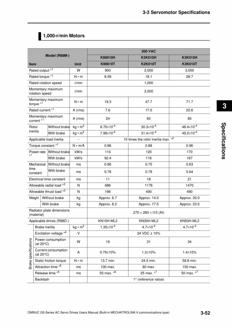
3-52
3-3 Servomotor Specifications
OMNUC G5-Series AC Servo Drives Users Manual (Built-in MECHATROLINK-II communications type)
3
Sp
ec
ifica
tion
s
1,000-r/min Motors
Model (R88M-)
Item Unit
200 VAC
K90010H K2K010H K3K010H
K90010T K2K010T K3K010T
Rated output *1 W 900 2,000 3,000
Rated torque *1 N • m 8.59 19.1 28.7
Rated rotation speed r/min 1,000
Momentary maximum
rotation speedr/min 2,000
Momentary maximum
torque *1 N • m 19.3 47.7 71.7
Rated current *1 A (rms) 7.6 17.0 22.6
Momentary maximum
current *1 A (rms) 24 60 80
Rotor
inertia
Without brake kg • m2 6.70×10⁻⁴ 30.3×10⁻⁴ 48.4×10⁻⁴
With brake kg • m2 7.99×10⁻⁴ 31.4×10⁻⁴ 49.2×10⁻⁴
Applicable load inertia − 10 times the rotor inertia max. *2
Torque constant *1 N • m/A 0.86 0.88 0.96
Power rate
*1 Without brake kW/s 110 120 170
With brake kW/s 92.4 116 167
Mechanical
time
constant
Without brake ms 0.66 0.75 0.63
With brake ms 0.78 0.78 0.64
Electrical time constant ms 11 18 21
Allowable radial load *3 N 686 1176 1470
Allowable thrust load *3 N 196 490 490
Weight Without brake kg Approx. 6.7 Approx. 14.0 Approx. 20.0
With brake kg Approx. 8.2 Approx. 17.5 Approx. 23.5
Radiator plate dimensions
(material)270 × 260 × t15 (AI)
Applicable drives (R88D-) KN15H-ML2 KN30H-ML2 KN50H-ML2
Bra
ke
sp
ecific
ation
s
Brake inertia kg • m2 1.35×10⁻⁴ 4.7×10⁻⁴ 4.7×10⁻⁴
Excitation voltage *4 V 24 VDC ± 10%
Power consumption
(at 20°C)W 19 31 34
Current consumption
(at 20°C)A 0.79±10% 1.3±10% 1.4±10%
Static friction torque N • m 13.7 min. 24.5 min. 58.8 min.
Attraction time *5 ms 100 max. 80 max. 150 max.
Release time *5 ms 50 max. *6 25 max. *7 50 max. *7
Backlash 1° (reference value)
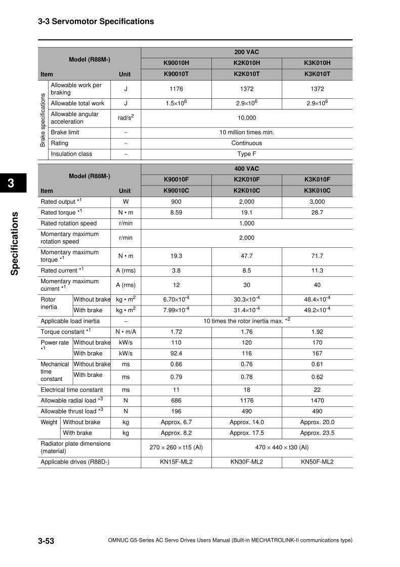
3-53
3-3 Servomotor Specifications
OMNUC G5-Series AC Servo Drives Users Manual (Built-in MECHATROLINK-II communications type)
3
Sp
ecif
ica
tio
ns
Model (R88M-)
Item Unit
200 VAC
K90010H K2K010H K3K010H
K90010T K2K010T K3K010T
Bra
ke
spe
cific
atio
ns
Allowable work per
brakingJ 1176 1372 1372
Allowable total work J 1.5×10⁶ 2.9×10⁶ 2.9×10⁶
Allowable angular
accelerationrad/s2 10,000
Brake limit − 10 million times min.
Rating − Continuous
Insulation class − Type F
Model (R88M-)
Item Unit
400 VAC
K90010F K2K010F K3K010F
K90010C K2K010C K3K010C
Rated output *1 W 900 2,000 3,000
Rated torque *1 N • m 8.59 19.1 28.7
Rated rotation speed r/min 1,000
Momentary maximum
rotation speedr/min 2,000
Momentary maximum
torque *1 N • m 19.3 47.7 71.7
Rated current *1 A (rms) 3.8 8.5 11.3
Momentary maximum
current *1 A (rms) 12 30 40
Rotor
inertia
Without brake kg • m2 6.70×10⁻⁴ 30.3×10⁻⁴ 48.4×10⁻⁴
With brake kg • m2 7.99×10⁻⁴ 31.4×10⁻⁴ 49.2×10⁻⁴
Applicable load inertia − 10 times the rotor inertia max. *2
Torque constant *1 N • m/A 1.72 1.76 1.92
Power rate
*1 Without brake kW/s 110 120 170
With brake kW/s 92.4 116 167
Mechanical
time
constant
Without brake ms 0.66 0.76 0.61
With brake ms 0.79 0.78 0.62
Electrical time constant ms 11 18 22
Allowable radial load *3 N 686 1176 1470
Allowable thrust load *3 N 196 490 490
Weight Without brake kg Approx. 6.7 Approx. 14.0 Approx. 20.0
With brake kg Approx. 8.2 Approx. 17.5 Approx. 23.5
Radiator plate dimensions
(material)270 × 260 × t15 (AI) 470 × 440 × t30 (AI)
Applicable drives (R88D-) KN15F-ML2 KN30F-ML2 KN50F-ML2
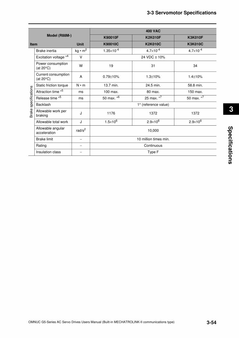
3-54
3-3 Servomotor Specifications
OMNUC G5-Series AC Servo Drives Users Manual (Built-in MECHATROLINK-II communications type)
3
Sp
ec
ifica
tion
s
Model (R88M-)
Item Unit
400 VAC
K90010F K2K010F K3K010F
K90010C K2K010C K3K010C
Bra
ke
spe
cific
atio
ns
Brake inertia kg • m2 1.35×10⁻⁴ 4.7×10⁻⁴ 4.7×10⁻⁴
Excitation voltage *4 V 24 VDC ± 10%
Power consumption
(at 20°C)W 19 31 34
Current consumption
(at 20°C)A 0.79±10% 1.3±10% 1.4±10%
Static friction torque N • m 13.7 min. 24.5 min. 58.8 min.
Attraction time *5 ms 100 max. 80 max. 150 max.
Release time *5 ms 50 max. *6 25 max. *7 50 max. *7
Backlash 1° (reference value)
Allowable work per
brakingJ 1176 1372 1372
Allowable total work J 1.5×10⁶ 2.9×10⁶ 2.9×10⁶
Allowable angular
accelerationrad/s2 10,000
Brake limit − 10 million times min.
Rating − Continuous
Insulation class − Type F
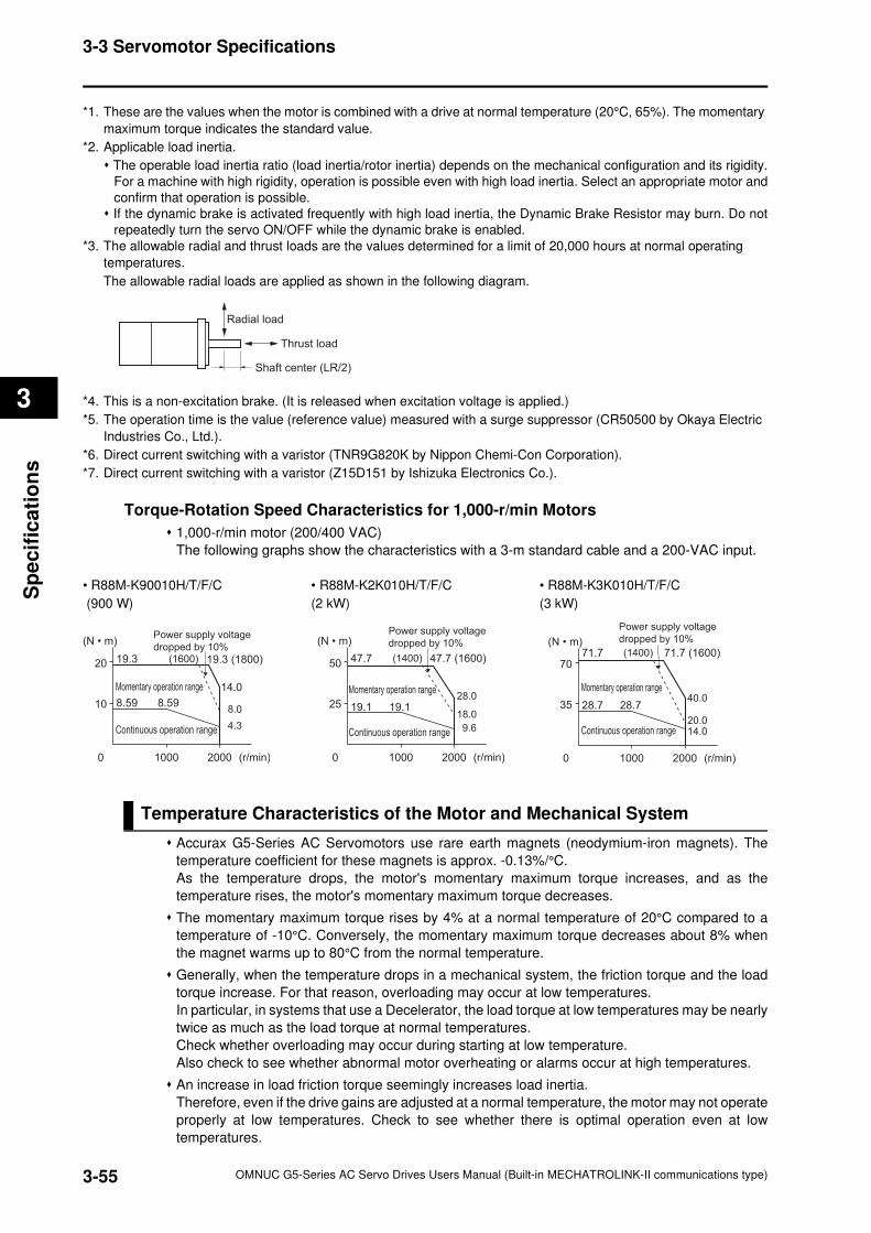
3-55
3-3 Servomotor Specifications
OMNUC G5-Series AC Servo Drives Users Manual (Built-in MECHATROLINK-II communications type)
3
Sp
ecif
ica
tio
ns
*1. These are the values when the motor is combined with a drive at normal temperature (20°C, 65%). The momentary
maximum torque indicates the standard value.
*2. Applicable load inertia.
The operable load inertia ratio (load inertia/rotor inertia) depends on the mechanical configuration and its rigidity.
For a machine with high rigidity, operation is possible even with high load inertia. Select an appropriate motor and
confirm that operation is possible.
If the dynamic brake is activated frequently with high load inertia, the Dynamic Brake Resistor may burn. Do not
repeatedly turn the servo ON/OFF while the dynamic brake is enabled.
*3. The allowable radial and thrust loads are the values determined for a limit of 20,000 hours at normal operating
temperatures.
The allowable radial loads are applied as shown in the following diagram.
*4. This is a non-excitation brake. (It is released when excitation voltage is applied.)
*5. The operation time is the value (reference value) measured with a surge suppressor (CR50500 by Okaya Electric
Industries Co., Ltd.).
*6. Direct current switching with a varistor (TNR9G820K by Nippon Chemi-Con Corporation).
*7. Direct current switching with a varistor (Z15D151 by Ishizuka Electronics Co.).
Torque-Rotation Speed Characteristics for 1,000-r/min Motors
1,000-r/min motor (200/400 VAC)
The following graphs show the characteristics with a 3-m standard cable and a 200-VAC input.
• R88M-K90010H/T/F/C • R88M-K2K010H/T/F/C • R88M-K3K010H/T/F/C
(900 W) (2 kW) (3 kW)
Temperature Characteristics of the Motor and Mechanical System
Accurax G5-Series AC Servomotors use rare earth magnets (neodymium-iron magnets). The
temperature coefficient for these magnets is approx. -0.13%/°C.
As the temperature drops, the motor's momentary maximum torque increases, and as the
temperature rises, the motor's momentary maximum torque decreases.
The momentary maximum torque rises by 4% at a normal temperature of 20°C compared to a
temperature of -10°C. Conversely, the momentary maximum torque decreases about 8% when
the magnet warms up to 80°C from the normal temperature.
Generally, when the temperature drops in a mechanical system, the friction torque and the load
torque increase. For that reason, overloading may occur at low temperatures.
In particular, in systems that use a Decelerator, the load torque at low temperatures may be nearly
twice as much as the load torque at normal temperatures.
Check whether overloading may occur during starting at low temperature.
Also check to see whether abnormal motor overheating or alarms occur at high temperatures.
An increase in load friction torque seemingly increases load inertia.
Therefore, even if the drive gains are adjusted at a normal temperature, the motor may not operate
properly at low temperatures. Check to see whether there is optimal operation even at low
temperatures.
Radial load
Thrust load
Shaft center (LR/2)
10
0
20 19.3 (1800)19.3
8.598.59
1000 2000 (r/min)
14.0
8.0
4.3
(1600)
Power supply voltage
dropped by 10%
Continuous operation range
Momentary operation range
(N • m)
25
0
50
1000 2000 (r/min)
19.119.1
47.7 (1600)47.7
28.0
18.0
9.6
(1400)
Power supply voltage
dropped by 10%
Continuous operation range
Momentary operation range
(N • m)
35
0
70
1000 2000 (r/min)
28.728.7
71.7 (1600)71.7
40.0
20.014.0
(1400)
Power supply voltage
dropped by 10%(N • m)
Continuous operation range
Momentary operation range
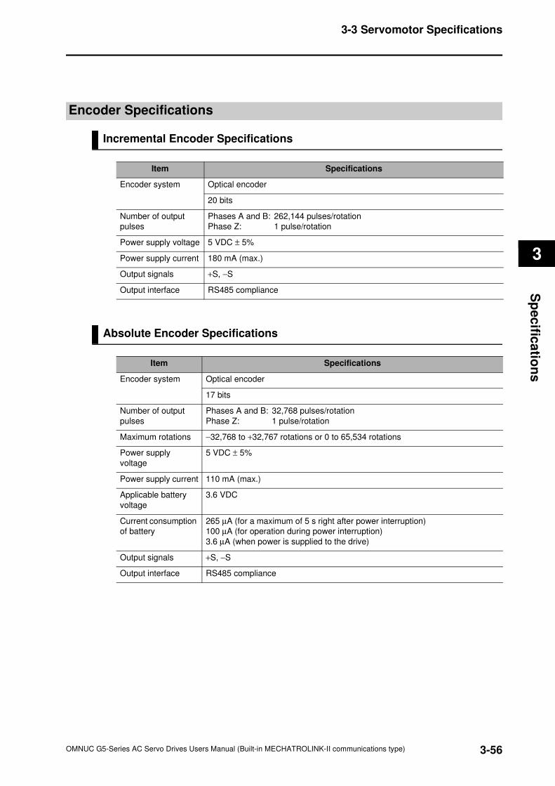
3-56
3-3 Servomotor Specifications
OMNUC G5-Series AC Servo Drives Users Manual (Built-in MECHATROLINK-II communications type)
3
Sp
ec
ifica
tion
s
Encoder Specifications
Incremental Encoder Specifications
Absolute Encoder Specifications
Item Specifications
Encoder system Optical encoder
20 bits
Number of output
pulses
Phases A and B: 262,144 pulses/rotation
Phase Z: 1 pulse/rotation
Power supply voltage 5 VDC ± 5%
Power supply current 180 mA (max.)
Output signals +S, −S
Output interface RS485 compliance
Item Specifications
Encoder system Optical encoder
17 bits
Number of output
pulses
Phases A and B: 32,768 pulses/rotation
Phase Z: 1 pulse/rotation
Maximum rotations −32,768 to +32,767 rotations or 0 to 65,534 rotations
Power supply
voltage
5 VDC ± 5%
Power supply current 110 mA (max.)
Applicable battery
voltage
3.6 VDC
Current consumption
of battery
265 µA (for a maximum of 5 s right after power interruption)
100 µA (for operation during power interruption)
3.6 µA (when power is supplied to the drive)
Output signals +S, −S
Output interface RS485 compliance
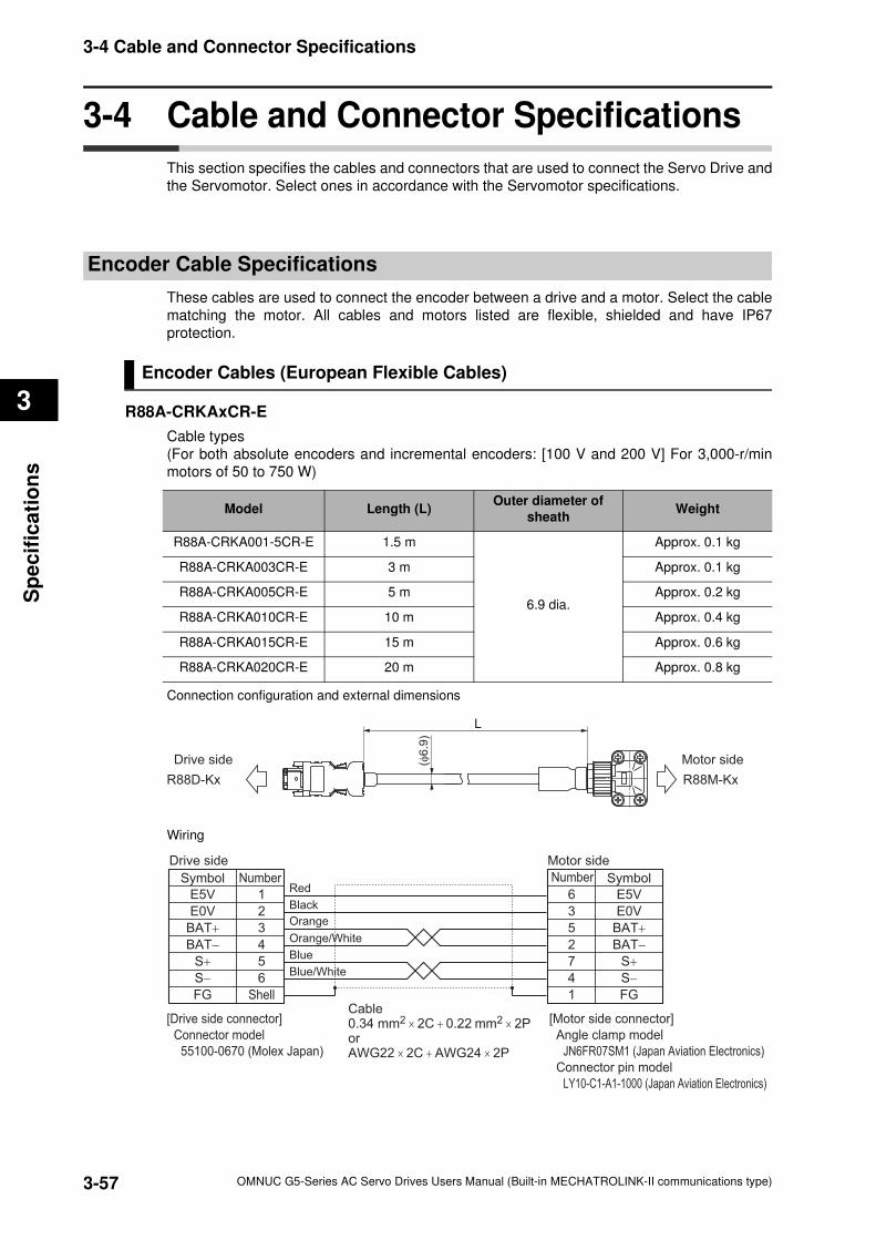
3-57
3-4 Cable and Connector Specifications
OMNUC G5-Series AC Servo Drives Users Manual (Built-in MECHATROLINK-II communications type)
3
Sp
ecif
ica
tio
ns
3-4 Cable and Connector Specifications
This section specifies the cables and connectors that are used to connect the Servo Drive and
the Servomotor. Select ones in accordance with the Servomotor specifications.
Encoder Cable Specifications
These cables are used to connect the encoder between a drive and a motor. Select the cable
matching the motor. All cables and motors listed are flexible, shielded and have IP67
protection.
Encoder Cables (European Flexible Cables)
R88A-CRKAxCR-E
Cable types
(For both absolute encoders and incremental encoders: [100 V and 200 V] For 3,000-r/min
motors of 50 to 750 W)
Connection configuration and external dimensions
Wiring
Model Length (L)Outer diameter of
sheathWeight
R88A-CRKA001-5CR-E 1.5 m
6.9 dia.
Approx. 0.1 kg
R88A-CRKA003CR-E 3 m Approx. 0.1 kg
R88A-CRKA005CR-E 5 m Approx. 0.2 kg
R88A-CRKA010CR-E 10 m Approx. 0.4 kg
R88A-CRKA015CR-E 15 m Approx. 0.6 kg
R88A-CRKA020CR-E 20 m Approx. 0.8 kg
L
(φ6
.9)
Drive side Motor side
R88D-Kx R88M-Kx
Symbol
Drive side
E5V 1
E0V 2
BAT+ 3
BAT− 4
S+ 5
S− 6
FG Shell
Black
Cable 0.34 mm2 × 2C + 0.22 mm2 × 2PorAWG22 × 2C + AWG24 × 2P
6 E5V
Symbol
Motor side
3
5
2
7
4
E0V
BAT+
BAT−
S+
S−
FG1
[Motor side connector]
Angle clamp model
JN6FR07SM1 (Japan Aviation Electronics)
Connector pin model
LY10-C1-A1-1000 (Japan Aviation Electronics)
[Drive side connector]
Connector model
55100-0670 (Molex Japan)
Red
Orange
Orange/White
Blue
Blue/White
Number Number
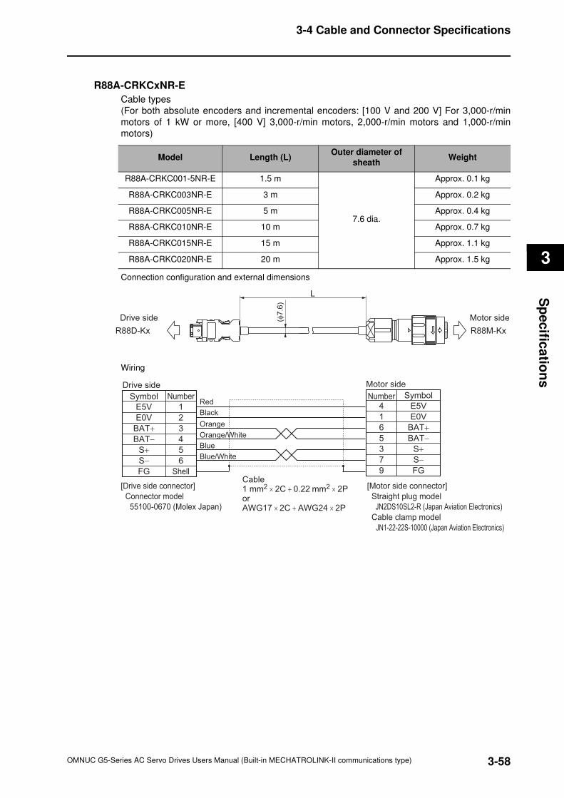
3-58
3-4 Cable and Connector Specifications
OMNUC G5-Series AC Servo Drives Users Manual (Built-in MECHATROLINK-II communications type)
3
Sp
ec
ifica
tion
s
R88A-CRKCxNR-E
Cable types
(For both absolute encoders and incremental encoders: [100 V and 200 V] For 3,000-r/min
motors of 1 kW or more, [400 V] 3,000-r/min motors, 2,000-r/min motors and 1,000-r/min
motors)
Connection configuration and external dimensions
Wiring
Model Length (L)Outer diameter of
sheathWeight
R88A-CRKC001-5NR-E 1.5 m
7.6 dia.
Approx. 0.1 kg
R88A-CRKC003NR-E 3 m Approx. 0.2 kg
R88A-CRKC005NR-E 5 m Approx. 0.4 kg
R88A-CRKC010NR-E 10 m Approx. 0.7 kg
R88A-CRKC015NR-E 15 m Approx. 1.1 kg
R88A-CRKC020NR-E 20 m Approx. 1.5 kg
L
(φ7
.6)
Drive side Motor side
R88D-Kx R88M-Kx
Symbol
Drive side
E5V 1
E0V 2
BAT+ 3
BAT− 4
S+ 5
S− 6
FG ShellCable1 mm2 × 2C + 0.22 mm2 × 2PorAWG17 × 2C + AWG24 × 2P
4 E5V
Symbol
Motor side
1
6
5
3
7
E0V
BAT+
BAT−
S+
S−
FG9
[Motor side connector]
Straight plug model
JN2DS10SL2-R (Japan Aviation Electronics)
Cable clamp model
JN1-22-22S-10000 (Japan Aviation Electronics)
[Drive side connector]
Connector model
55100-0670 (Molex Japan)
Orange
Orange/White
Blue
Blue/White
Black
RedNumber Number
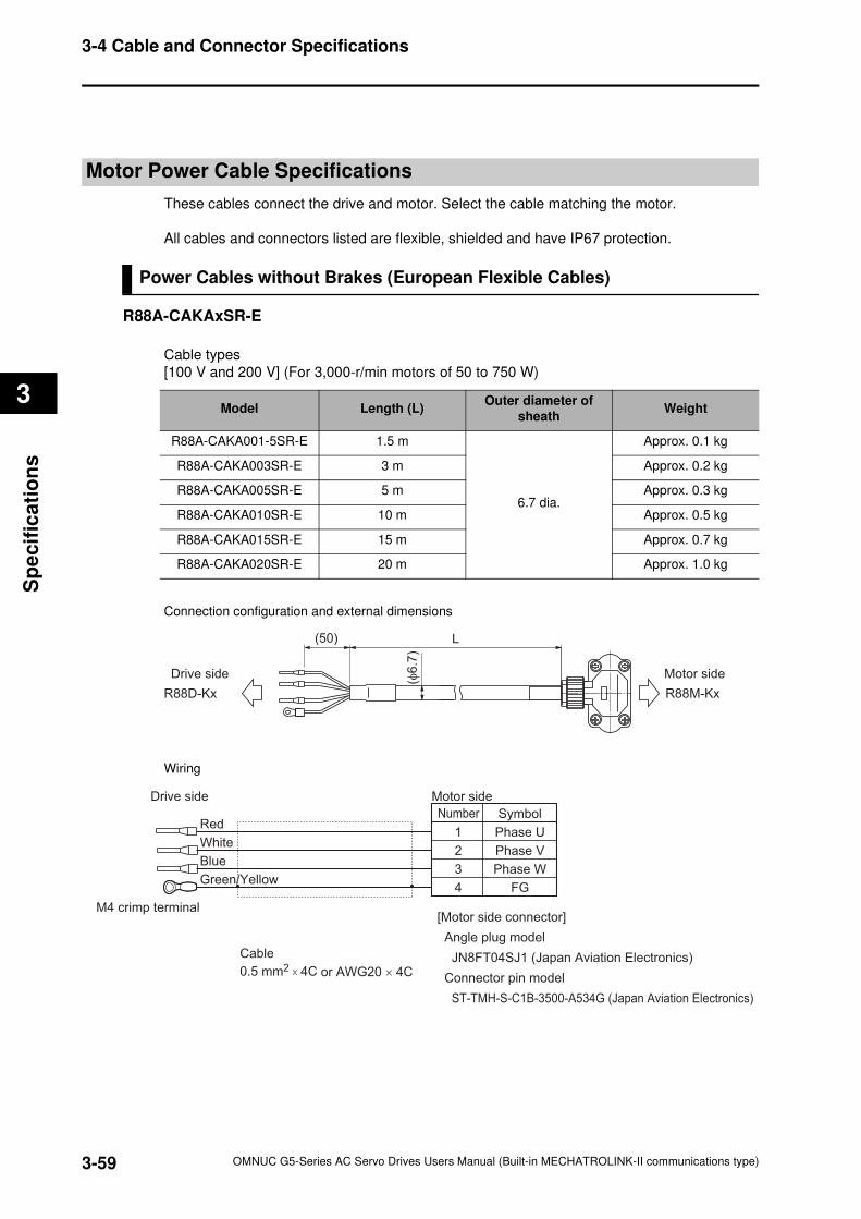
3-59
3-4 Cable and Connector Specifications
OMNUC G5-Series AC Servo Drives Users Manual (Built-in MECHATROLINK-II communications type)
3
Sp
ecif
ica
tio
ns
Motor Power Cable Specifications
These cables connect the drive and motor. Select the cable matching the motor.
All cables and connectors listed are flexible, shielded and have IP67 protection.
Power Cables without Brakes (European Flexible Cables)
R88A-CAKAxSR-E
Cable types
[100 V and 200 V] (For 3,000-r/min motors of 50 to 750 W)
Connection configuration and external dimensions
Wiring
Model Length (L)Outer diameter of
sheathWeight
R88A-CAKA001-5SR-E 1.5 m
6.7 dia.
Approx. 0.1 kg
R88A-CAKA003SR-E 3 m Approx. 0.2 kg
R88A-CAKA005SR-E 5 m Approx. 0.3 kg
R88A-CAKA010SR-E 10 m Approx. 0.5 kg
R88A-CAKA015SR-E 15 m Approx. 0.7 kg
R88A-CAKA020SR-E 20 m Approx. 1.0 kg
(50) L
(φ6
.7)
Drive side Motor side
R88D-Kx R88M-Kx
1
2
3
4
Phase U
Phase V
Phase W
FG
Symbol
Drive side
Red
White
Blue
Green/Yellow
Cable
0.5 mm2 × 4C or AWG20 × 4C
M4 crimp terminal
Motor side
[Motor side connector]
Angle plug model
JN8FT04SJ1 (Japan Aviation Electronics)
Connector pin model
ST-TMH-S-C1B-3500-A534G (Japan Aviation Electronics)
Number
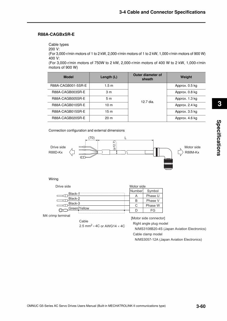
3-60
3-4 Cable and Connector Specifications
OMNUC G5-Series AC Servo Drives Users Manual (Built-in MECHATROLINK-II communications type)
3
Sp
ec
ifica
tion
s
R88A-CAGBxSR-E
Cable types
200 V:
(For 3,000-r/min motors of 1 to 2 kW, 2,000-r/min motors of 1 to 2 kW, 1,000-r/min motors of 900 W)
400 V:
(For 3,000-r/min motors of 750W to 2 kW, 2,000-r/min motors of 400 W to 2 kW, 1,000-r/min
motors of 900 W)
Connection configuration and external dimensions
Wiring
Model Length (L)Outer diameter of
sheathWeight
R88A-CAGB001-5SR-E 1.5 m
12.7 dia.
Approx. 0.5 kg
R88A-CAGB003SR-E 3 m Approx. 0.8 kg
R88A-CAGB005SR-E 5 m Approx. 1.3 kg
R88A-CAGB010SR-E 10 m Approx. 2.4 kg
R88A-CAGB015SR-E 15 m Approx. 3.5 kg
R88A-CAGB020SR-E 20 m Approx. 4.6 kg
(70) L
(φ1
2.7
)
Drive side Motor side
R88D-Kx R88M-Kx
Number
A
B
C
D
Phase U
Phase V
Phase W
FG
Symbol
Drive side
Black-1
Black-2
Black-3
Green/Yellow
Cable
2.5 mm2 × 4C or AWG14 × 4C
M4 crimp terminal
Motor side
[Motor side connector]
Right angle plug model
N/MS3108B20-4S (Japan Aviation Electronics)
Cable clamp model
N/MS3057-12A (Japan Aviation Electronics)
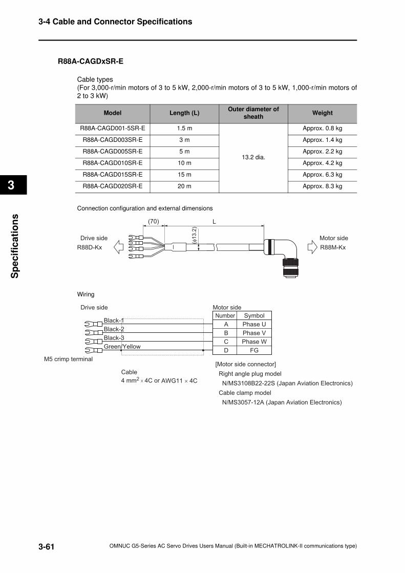
3-61
3-4 Cable and Connector Specifications
OMNUC G5-Series AC Servo Drives Users Manual (Built-in MECHATROLINK-II communications type)
3
Sp
ecif
ica
tio
ns
R88A-CAGDxSR-E
Cable types
(For 3,000-r/min motors of 3 to 5 kW, 2,000-r/min motors of 3 to 5 kW, 1,000-r/min motors of
2 to 3 kW)
Connection configuration and external dimensions
Wiring
Model Length (L)Outer diameter of
sheathWeight
R88A-CAGD001-5SR-E 1.5 m
13.2 dia.
Approx. 0.8 kg
R88A-CAGD003SR-E 3 m Approx. 1.4 kg
R88A-CAGD005SR-E 5 m Approx. 2.2 kg
R88A-CAGD010SR-E 10 m Approx. 4.2 kg
R88A-CAGD015SR-E 15 m Approx. 6.3 kg
R88A-CAGD020SR-E 20 m Approx. 8.3 kg
(70) L
(φ1
3.2
)
Drive side Motor side
R88D-Kx R88M-Kx
A
B
C
D
Phase U
Phase V
Phase W
FG
SymbolNumber
Drive side
Black-1
Black-2
Black-3
Green/Yellow
Cable
4 mm2 × 4C or AWG11 × 4C
M5 crimp terminal
Motor side
[Motor side connector]
Right angle plug model
N/MS3108B22-22S (Japan Aviation Electronics)
Cable clamp model
N/MS3057-12A (Japan Aviation Electronics)
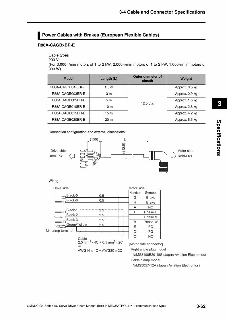
3-62
3-4 Cable and Connector Specifications
OMNUC G5-Series AC Servo Drives Users Manual (Built-in MECHATROLINK-II communications type)
3
Sp
ec
ifica
tion
s
Power Cables with Brakes (European Flexible Cables)
R88A-CAGBxBR-E
Cable types
200 V:
(For 3,000-r/min motors of 1 to 2 kW, 2,000-r/min motors of 1 to 2 kW, 1,000-r/min motors of
900 W)
Connection configuration and external dimensions
Wiring
Model Length (L)Outer diameter of
sheathWeight
R88A-CAGB001-5BR-E 1.5 m
12.5 dia.
Approx. 0.5 kg
R88A-CAGB003BR-E 3 m Approx. 0.9 kg
R88A-CAGB005BR-E 5 m Approx. 1.5 kg
R88A-CAGB010BR-E 10 m Approx. 2.8 kg
R88A-CAGB015BR-E 15 m Approx. 4.2 kg
R88A-CAGB020BR-E 20 m Approx. 5.5 kg
L(150)
(φ1
2.5
)
Drive side Motor side
R88D-Kx R88M-Kx
Number
G
H
A
F
Brake
Brake
NC
Phase U
Symbol
Drive side
Black-5
Black-6
Black-1
I
B
E
D
C
Phase W
FG
FG
NC
Phase VBlack-3
Green/Yellow
Black-2
Motor side
Cable 2.5 mm2 × 4C + 0.5 mm2 × 2C or
AWG14 × 4C + AWG20 × 2C
M4 crimp terminal
[Motor side connector]
Right angle plug model
N/MS3108B20-18S (Japan Aviation Electronics)
Cable clamp model
N/MS3057-12A (Japan Aviation Electronics)
0.5
0.5
2.5
2.5
2.5
2.5
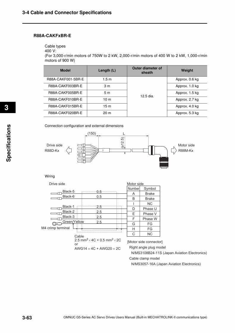
3-63
3-4 Cable and Connector Specifications
OMNUC G5-Series AC Servo Drives Users Manual (Built-in MECHATROLINK-II communications type)
3
Sp
ecif
ica
tio
ns
R88A-CAKFxBR-E
Cable types
400 V:
(For 3,000-r/min motors of 750W to 2 kW, 2,000-r/min motors of 400 W to 2 kW, 1,000-r/min
motors of 900 W)
Connection configuration and external dimensions
Wiring
Model Length (L)Outer diameter of
sheathWeight
R88A-CAKF001-5BR-E 1.5 m
12.5 dia.
Approx. 0.6 kg
R88A-CAKF003BR-E 3 m Approx. 1.0 kg
R88A-CAKF005BR-E 5 m Approx. 1.5 kg
R88A-CAKF010BR-E 10 m Approx. 2.7 kg
R88A-CAKF015BR-E 15 m Approx. 4.0 kg
R88A-CAKF020BR-E 20 m Approx. 5.3 kg
L(150)
(φ1
2.5
)
Drive side Motor side
R88D-Kx R88M-Kx
Number
A
B
I
D
Brake
Brake
NC
Phase U
Symbol
Drive side
Black-5
Black-6
Black-1
E
F
G
H
C
Phase W
FG
FG
NC
Phase VBlack-3
Green/Yellow
Black-2
Motor side
Cable 2.5 mm2 × 4C + 0.5 mm2 × 2C or
AWG14 × 4C + AWG20 × 2C
M4 crimp terminal
[Motor side connector]
Right angle plug model
N/MS3108B24-11S (Japan Aviation Electronics)
Cable clamp model
N/MS3057-16A (Japan Aviation Electronics)
0.5
0.5
2.5
2.5
2.5
2.5
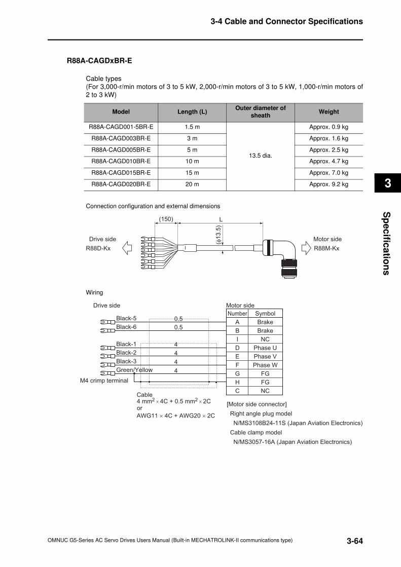
3-64
3-4 Cable and Connector Specifications
OMNUC G5-Series AC Servo Drives Users Manual (Built-in MECHATROLINK-II communications type)
3
Sp
ec
ifica
tion
s
R88A-CAGDxBR-E
Cable types
(For 3,000-r/min motors of 3 to 5 kW, 2,000-r/min motors of 3 to 5 kW, 1,000-r/min motors of
2 to 3 kW)
Connection configuration and external dimensions
Wiring
Model Length (L)Outer diameter of
sheathWeight
R88A-CAGD001-5BR-E 1.5 m
13.5 dia.
Approx. 0.9 kg
R88A-CAGD003BR-E 3 m Approx. 1.6 kg
R88A-CAGD005BR-E 5 m Approx. 2.5 kg
R88A-CAGD010BR-E 10 m Approx. 4.7 kg
R88A-CAGD015BR-E 15 m Approx. 7.0 kg
R88A-CAGD020BR-E 20 m Approx. 9.2 kg
L(150)(φ
13
.5)
Drive side Motor side
R88D-Kx R88M-Kx
Number
A
B
I
D
Brake
Brake
NC
Phase U
Symbol
Drive side
Black-5
Black-6
Black-1
E
F
G
H
C
Phase W
FG
FG
NC
Phase VBlack-3
Green/Yellow
Black-2
Motor side
Cable 4 mm2 × 4C + 0.5 mm2 × 2C or
AWG11 × 4C + AWG20 × 2C
M4 crimp terminal
[Motor side connector]
Right angle plug model
N/MS3108B24-11S (Japan Aviation Electronics)
Cable clamp model
N/MS3057-16A (Japan Aviation Electronics)
0.5
0.5
4
4
4
4
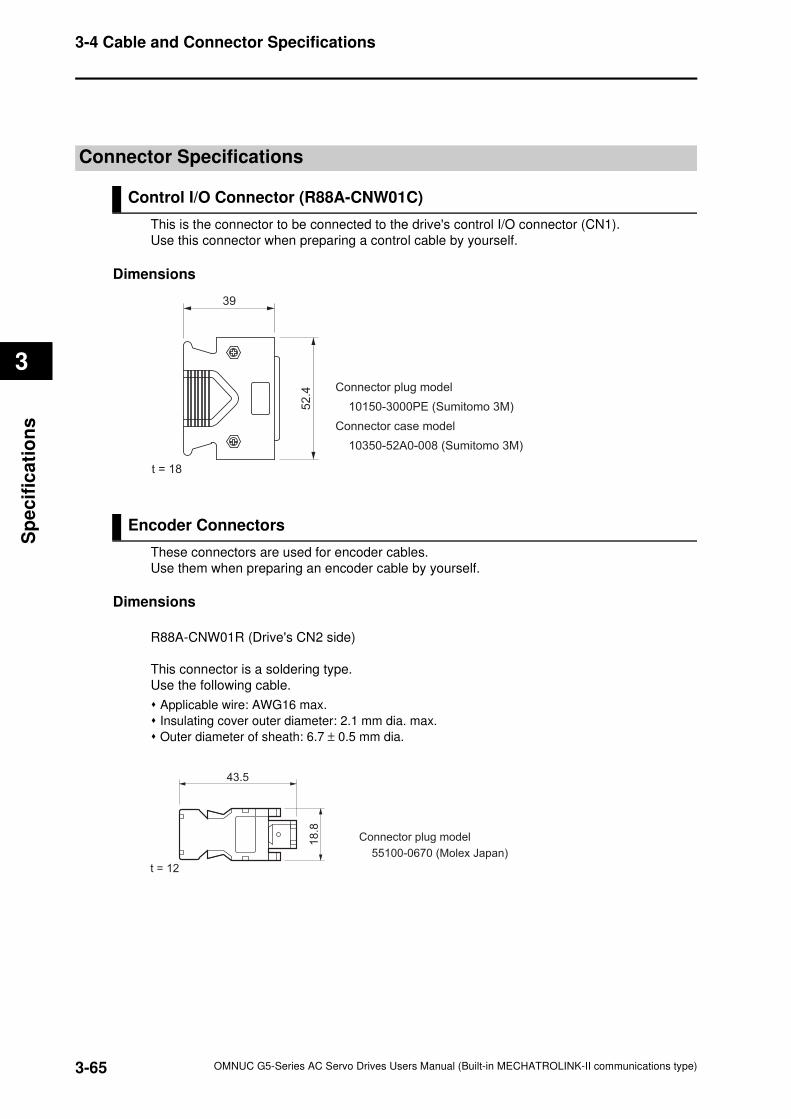
3-65
3-4 Cable and Connector Specifications
OMNUC G5-Series AC Servo Drives Users Manual (Built-in MECHATROLINK-II communications type)
3
Sp
ecif
ica
tio
ns
Connector Specifications
Control I/O Connector (R88A-CNW01C)
This is the connector to be connected to the drive's control I/O connector (CN1).
Use this connector when preparing a control cable by yourself.
Dimensions
Encoder Connectors
These connectors are used for encoder cables.
Use them when preparing an encoder cable by yourself.
Dimensions
R88A-CNW01R (Drive's CN2 side)
This connector is a soldering type.
Use the following cable.
Applicable wire: AWG16 max.
Insulating cover outer diameter: 2.1 mm dia. max.
Outer diameter of sheath: 6.7 ± 0.5 mm dia.
52
.439
t = 18
Connector plug model
10150-3000PE (Sumitomo 3M)
Connector case model
10350-52A0-008 (Sumitomo 3M)
t = 12
43.5
18
.8
Connector plug model
55100-0670 (Molex Japan)
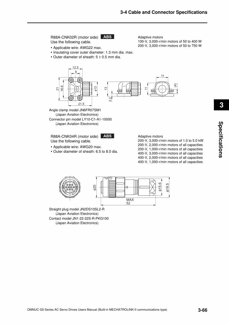
3-66
3-4 Cable and Connector Specifications
OMNUC G5-Series AC Servo Drives Users Manual (Built-in MECHATROLINK-II communications type)
3
Sp
ec
ifica
tion
s
Angle clamp model JN6FR07SM1
(Japan Aviation Electronics)
Connector pin model LY10-C1-A1-10000
(Japan Aviation Electronics)
Straight plug model JN2DS10SL2-R
(Japan Aviation Electronics)
Contact model JN1-22-22S-R-PKG100
(Japan Aviation Electronics)
R88A-CNK02R (motor side)
Use the following cable.
Applicable wire: AWG22 max.
Insulating cover outer diameter: 1.3 mm dia. max.
Outer diameter of sheath: 5 ± 0.5 mm dia.
Adaptive motors
100-V, 3,000-r/min motors of 50 to 400 W
200-V, 3,000-r/min motors of 50 to 750 W
ABS
12.5
21.5
φ1
3
21
16
.6
8
13
2.2
11
11
(4)
R88A-CNK04R (motor side)
Use the following cable.
Applicable wire: AWG20 max.
Outer diameter of sheath: 6.5 to 8.0 dia.
Adaptive motors
200-V, 3,000-r/min motors of 1.0 to 5.0 kW
200-V, 2,000-r/min motors of all capacities
200-V, 1,000-r/min motors of all capacities
400-V, 3,000-r/min motors of all capacities
400-V, 2,000-r/min motors of all capacities
400-V, 1,000-r/min motors of all capacities
ABS
3 1
47
10
J A E
8 φ1
5.6
MAX52
φ2
0
φ1
9.5
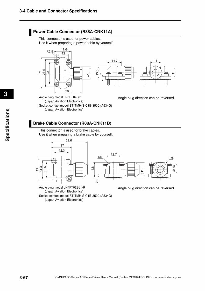
3-67
3-4 Cable and Connector Specifications
OMNUC G5-Series AC Servo Drives Users Manual (Built-in MECHATROLINK-II communications type)
3
Sp
ecif
ica
tio
ns
Power Cable Connector (R88A-CNK11A)
This connector is used for power cables.
Use it when preparing a power cable by yourself.
Angle plug model JN8FT04SJ1
(Japan Aviation Electronics)
Socket contact model ST-TMH-S-C1B-3500-(A534G)
(Japan Aviation Electronics)
Brake Cable Connector (R88A-CNK11B)
This connector is used for brake cables.
Use it when preparing a brake cable by yourself.
Angle plug model JN4FT02SJ1-R
(Japan Aviation Electronics)
Socket contact model ST-TMH-S-C1B-3500-(A534G)
(Japan Aviation Electronics)
17.6
28.8φ1
332
27
.6
22
12R5.5
14.7
13
.5
3 11
11
Angle plug direction can be reversed.
29.6
12.3
17
12
.5
14
.3
19
2.5
11
.8
R612.7
φ11
.6
(8.8
)
R4
Angle plug direction can be reversed.
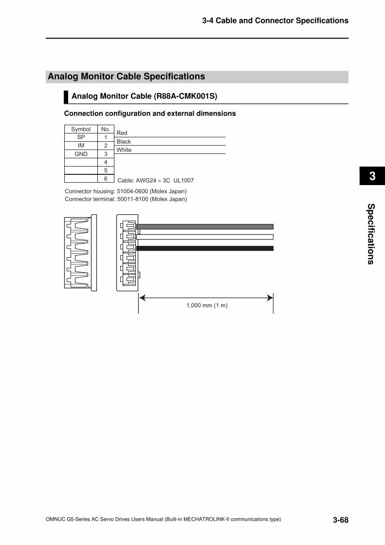
3-68
3-4 Cable and Connector Specifications
OMNUC G5-Series AC Servo Drives Users Manual (Built-in MECHATROLINK-II communications type)
3
Sp
ec
ifica
tion
s
Analog Monitor Cable Specifications
Analog Monitor Cable (R88A-CMK001S)
Connection configuration and external dimensions
No.
1
2
Symbol
Black
Red
White
Cable: AWG24 × 3C UL1007
3
4
5
6
Connector housing: 51004-0600 (Molex Japan)
Connector terminal: 50011-8100 (Molex Japan)
SP
IM
GND
1,000 mm (1 m)
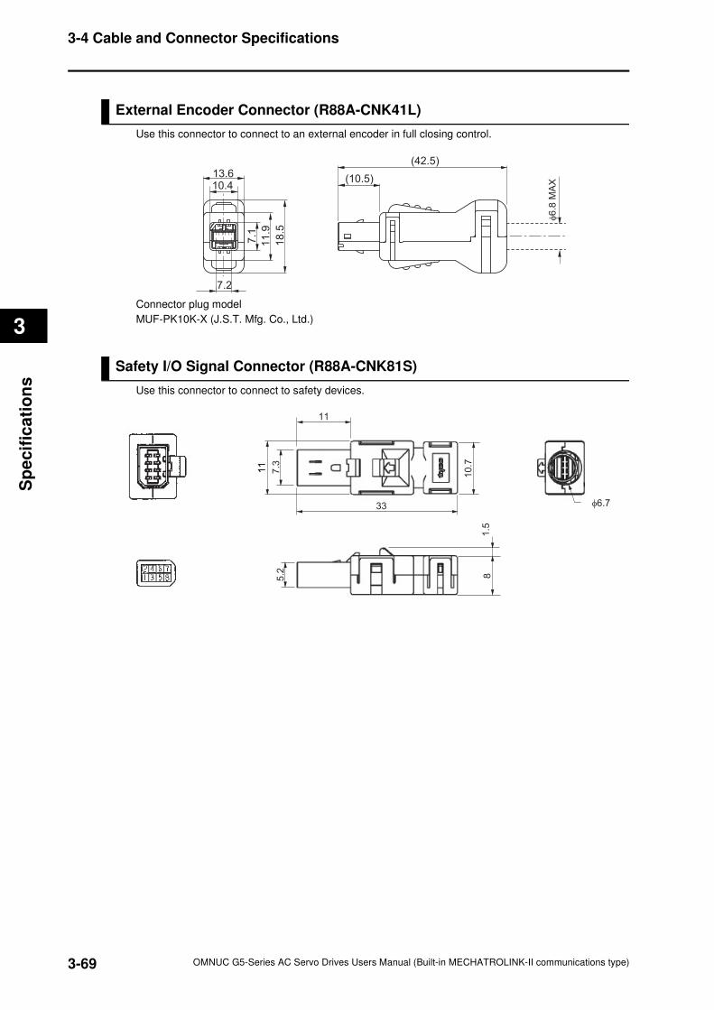
3-69
3-4 Cable and Connector Specifications
OMNUC G5-Series AC Servo Drives Users Manual (Built-in MECHATROLINK-II communications type)
3
Sp
ecif
ica
tio
ns
External Encoder Connector (R88A-CNK41L)
Use this connector to connect to an external encoder in full closing control.
Connector plug model
MUF-PK10K-X (J.S.T. Mfg. Co., Ltd.)
Safety I/O Signal Connector (R88A-CNK81S)
Use this connector to connect to safety devices.
7.2
13.610.4
7.1
11
.9
18
.5
(42.5)
(10.5)
φ6
.8 M
AX
7.3
5.2
11
11
10
.7
81
.5
11
33 φ6.7
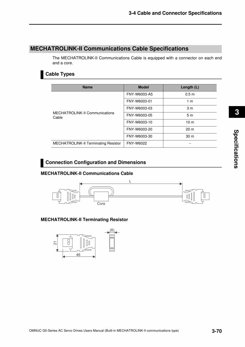
3-70
3-4 Cable and Connector Specifications
OMNUC G5-Series AC Servo Drives Users Manual (Built-in MECHATROLINK-II communications type)
3
Sp
ec
ifica
tion
s
MECHATROLINK-II Communications Cable Specifications
The MECHATROLINK-II Communications Cable is equipped with a connector on each end
and a core.
Cable Types
Connection Configuration and Dimensions
MECHATROLINK-II Communications Cable
MECHATROLINK-II Terminating Resistor
Name Model Length (L)
MECHATROLINK-II Communications
Cable
FNY-W6003-A5 0.5 m
FNY-W6003-01 1 m
FNY-W6003-03 3 m
FNY-W6003-05 5 m
FNY-W6003-10 10 m
FNY-W6003-20 20 m
FNY-W6003-30 30 m
MECHATROLINK-II Terminating Resistor FNY-W6022 −
L
Core
(8)
21
46
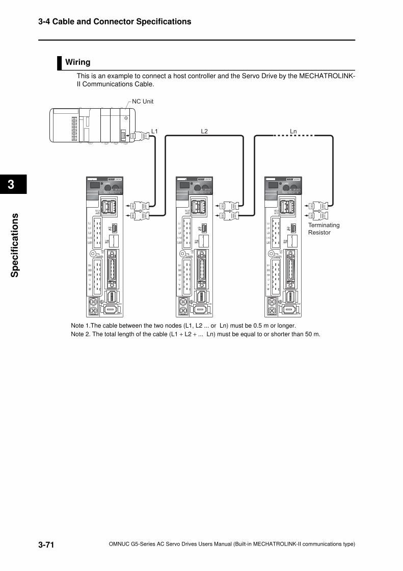
3-71
3-4 Cable and Connector Specifications
OMNUC G5-Series AC Servo Drives Users Manual (Built-in MECHATROLINK-II communications type)
3
Sp
ecif
ica
tio
ns
Wiring
This is an example to connect a host controller and the Servo Drive by the MECHATROLINK-
II Communications Cable.
Note 1.The cable between the two nodes (L1, L2 ... or Ln) must be 0.5 m or longer.
Note 2. The total length of the cable (L1 + L2 + ... Ln) must be equal to or shorter than 50 m.
01234567
89
ABCDE
NC Unit
L1 L2 Ln
Terminating
Resistor
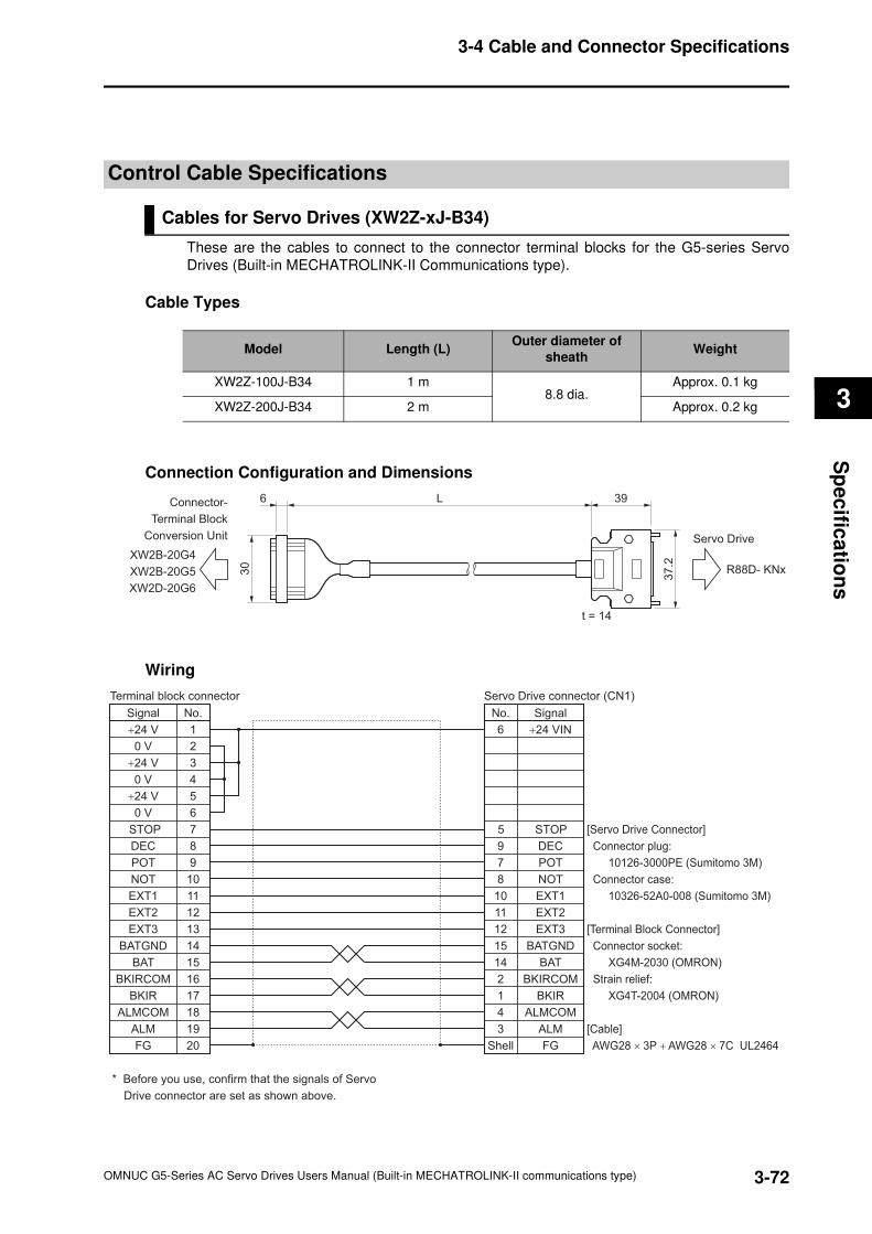
3-72
3-4 Cable and Connector Specifications
OMNUC G5-Series AC Servo Drives Users Manual (Built-in MECHATROLINK-II communications type)
3
Sp
ec
ifica
tion
s
Control Cable Specifications
Cables for Servo Drives (XW2Z-xJ-B34)
These are the cables to connect to the connector terminal blocks for the G5-series Servo
Drives (Built-in MECHATROLINK-II Communications type).
Cable Types
Connection Configuration and Dimensions
Wiring
Model Length (L)Outer diameter of
sheathWeight
XW2Z-100J-B34 1 m8.8 dia.
Approx. 0.1 kg
XW2Z-200J-B34 2 m Approx. 0.2 kg
37
.2
30
39L6
t = 14
R88D- KNx
Servo Drive
Connector-
Terminal Block
Conversion Unit
XW2B-20G4
XW2B-20G5
XW2D-20G6
1
2
3
4
5
6
7
8
9
10
11
12
13
14
15
16
17
18
19
20
No.
6 +24 VIN
DEC9
7 POT
8 NOT
10 EXT1
EXT211
12
2
1
EXT3
BATGND
14
15
BAT
BKIRCOM
BKIR
4
ALM3
ALMCOM
FG
No.
+24 V
0 V
+24 V
0 V
+24 V
0 V
DEC
POT
NOT
EXT1
EXT2
EXT3
BATGND
BAT
BKIRCOM
BKIR
ALM
ALMCOM
FG
STOP STOP5
Terminal block connector
[Servo Drive Connector]
Connector plug:
10126-3000PE (Sumitomo 3M)
Connector case:
10326-52A0-008 (Sumitomo 3M)
[Terminal Block Connector]
Connector socket:
XG4M-2030 (OMRON)
Strain relief:
XG4T-2004 (OMRON)
[Cable]
AWG28 × 3P + AWG28 × 7C UL2464
* Before you use, confirm that the signals of Servo
Drive connector are set as shown above.
Signal
Servo Drive connector (CN1)
Shell
Signal
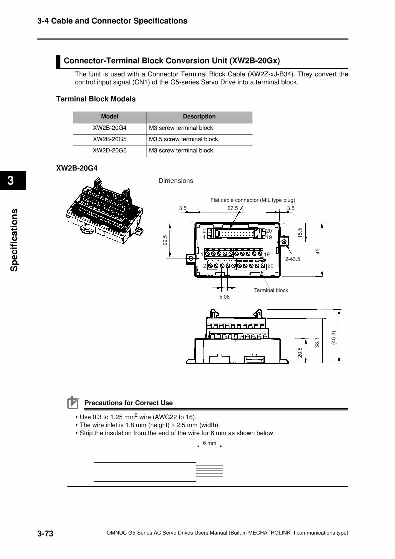
3-73
3-4 Cable and Connector Specifications
OMNUC G5-Series AC Servo Drives Users Manual (Built-in MECHATROLINK-II communications type)
3
Sp
ecif
ica
tio
ns
Connector-Terminal Block Conversion Unit (XW2B-20Gx)
The Unit is used with a Connector Terminal Block Cable (XW2Z-xJ-B34). They convert the
control input signal (CN1) of the G5-series Servo Drive into a terminal block.
Terminal Block Models
XW2B-20G4
Precautions for Correct Use
Use 0.3 to 1.25 mm2 wire (AWG22 to 16).
The wire inlet is 1.8 mm (height) × 2.5 mm (width).
Strip the insulation from the end of the wire for 6 mm as shown below.
Model Description
XW2B-20G4 M3 screw terminal block
XW2B-20G5 M3.5 screw terminal block
XW2D-20G6 M3 screw terminal block
3.5 3.5
2-φ3.5
67.5
5.08
29
.5 15
.52
0.5
38
.1
(45
.3)
45
2
1
1
2
20
19
19
20
Terminal block
Flat cable connector (MIL type plug)
Dimensions
6 mm
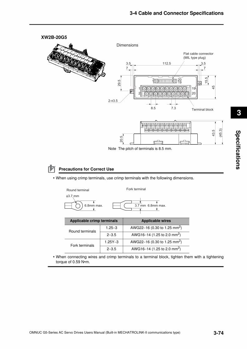
3-74
3-4 Cable and Connector Specifications
OMNUC G5-Series AC Servo Drives Users Manual (Built-in MECHATROLINK-II communications type)
3
Sp
ec
ifica
tion
s
XW2B-20G5
Note The pitch of terminals is 8.5 mm.
Precautions for Correct Use
When using crimp terminals, use crimp terminals with the following dimensions.
When connecting wires and crimp terminals to a terminal block, tighten them with a tightening
torque of 0.59 N•m.
2
1
12
20
19
1920
(45
.3)
43
.5
29
.5
7
8.5 7.3
3.5
7
3.5112.5
15
.5
45
2-φ3.5
20
.5
Dimensions
Flat cable connector
(MIL type plug)
Terminal block
φ3.7 mm
3.7 mm6.8mm max. 6.8mm max.
Round terminal Fork terminal
Applicable crimp terminals Applicable wires
Round terminals1.25−3 AWG22−16 (0.30 to 1.25 mm2)
2−3.5 AWG16−14 (1.25 to 2.0 mm2)
Fork terminals1.25Y−3 AWG22−16 (0.30 to 1.25 mm2)
2−3.5 AWG16−14 (1.25 to 2.0 mm2)
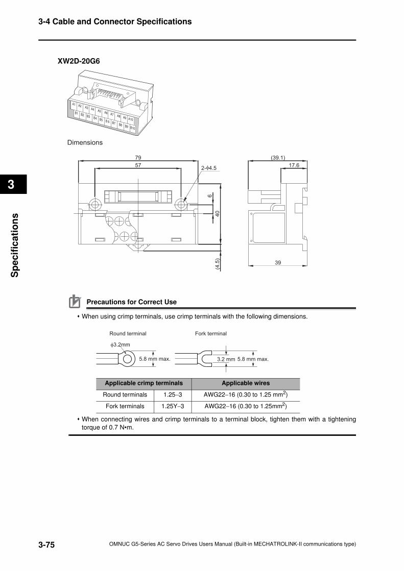
3-75
3-4 Cable and Connector Specifications
OMNUC G5-Series AC Servo Drives Users Manual (Built-in MECHATROLINK-II communications type)
3
Sp
ecif
ica
tio
ns
XW2D-20G6
Precautions for Correct Use
When using crimp terminals, use crimp terminals with the following dimensions.
When connecting wires and crimp terminals to a terminal block, tighten them with a tightening
torque of 0.7 N•m.
79 (39.1)
39
57 17.6
6
40
(4.5
)
2-φ4.5
Dimensions
φ3.2mm
3.2 mm
Round terminal Fork terminal
5.8 mm max. 5.8 mm max.
Applicable crimp terminals Applicable wires
Round terminals 1.25−3 AWG22−16 (0.30 to 1.25 mm2)
Fork terminals 1.25Y−3 AWG22−16 (0.30 to 1.25mm2)
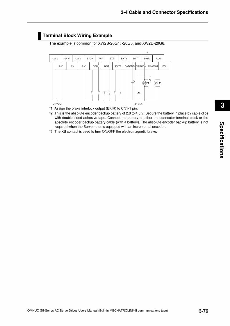
3-76
3-4 Cable and Connector Specifications
OMNUC G5-Series AC Servo Drives Users Manual (Built-in MECHATROLINK-II communications type)
3
Sp
ec
ifica
tion
s
Terminal Block Wiring Example
The example is common for XW2B-20G4, -20G5, and XW2D-20G6.
*1. Assign the brake interlock output (BKIR) to CN1-1 pin.
*2. This is the absolute encoder backup battery of 2.8 to 4.5 V. Secure the battery in place by cable clips
with double-sided adhesive tape. Connect the battery to either the connector terminal block or the
absolute encoder backup battery cable (with a battery). The absolute encoder backup battery is not
required when the Servomotor is equipped with an incremental encoder.
*3. The XB contact is used to turn ON/OFF the electromagnetic brake.
+24 V
0 V
+24 V +24 V POT EXT1 EXT3 BAT BKIR ALM
0 V 0 V DEC EXT2 BATGNDNOT BKIRCOM FG
24 VDC 24 VDC
*3*2
*1
ALMCOM
XB X1
STOP
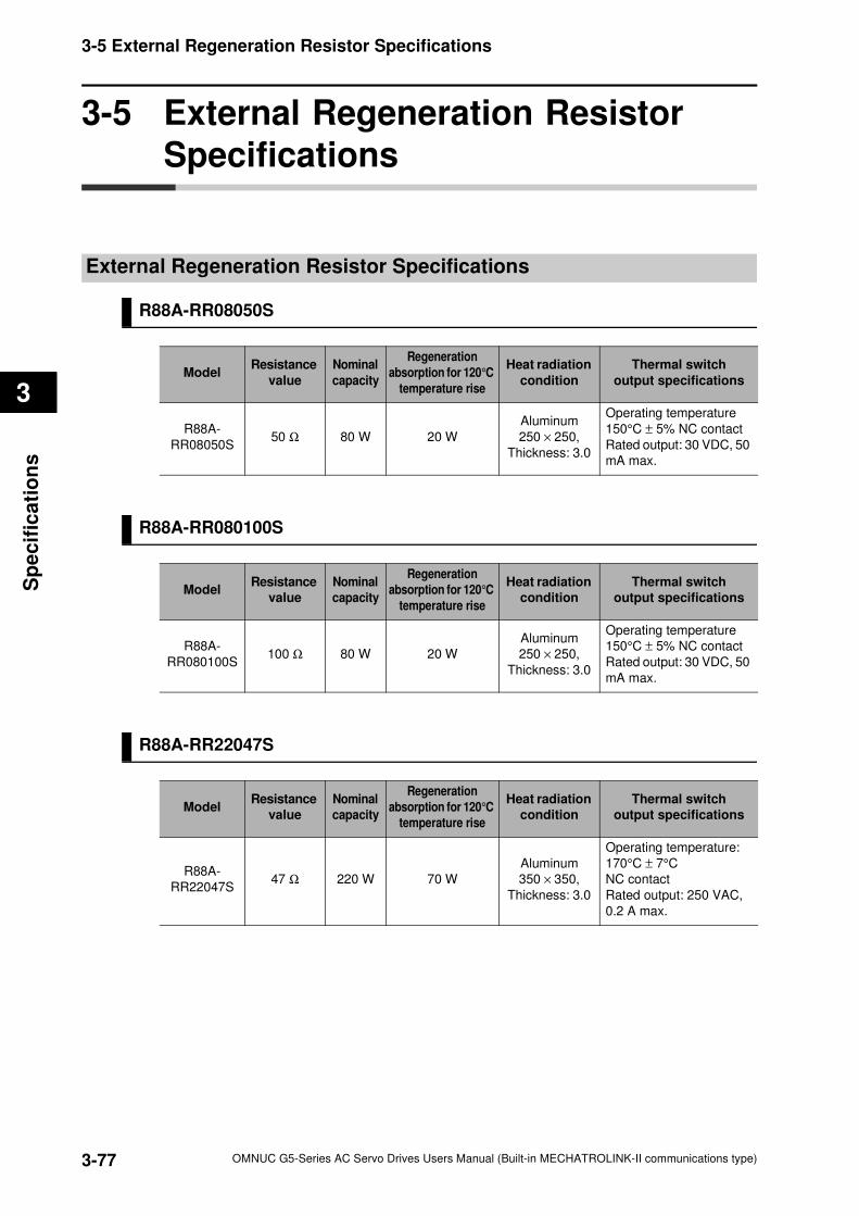
3-77
3-5 External Regeneration Resistor Specifications
OMNUC G5-Series AC Servo Drives Users Manual (Built-in MECHATROLINK-II communications type)
3
Sp
ecif
ica
tio
ns
3-5 External Regeneration Resistor
Specifications
External Regeneration Resistor Specifications
R88A-RR08050S
R88A-RR080100S
R88A-RR22047S
ModelResistance
value
Nominal
capacity
Regeneration
absorption for 120°C
temperature rise
Heat radiation
condition
Thermal switch
output specifications
R88A-
RR08050S50 Ω 80 W 20 W
Aluminum
250 × 250,
Thickness: 3.0
Operating temperature
150°C ± 5% NC contact
Rated output: 30 VDC, 50
mA max.
ModelResistance
value
Nominal
capacity
Regeneration
absorption for 120°C
temperature rise
Heat radiation
condition
Thermal switch
output specifications
R88A-
RR080100S100 Ω 80 W 20 W
Aluminum
250 × 250,
Thickness: 3.0
Operating temperature
150°C ± 5% NC contact
Rated output: 30 VDC, 50
mA max.
ModelResistance
value
Nominal
capacity
Regeneration
absorption for 120°C
temperature rise
Heat radiation
condition
Thermal switch
output specifications
R88A-
RR22047S47 Ω 220 W 70 W
Aluminum
350 × 350,
Thickness: 3.0
Operating temperature:
170°C ± 7°C
NC contact
Rated output: 250 VAC,
0.2 A max.
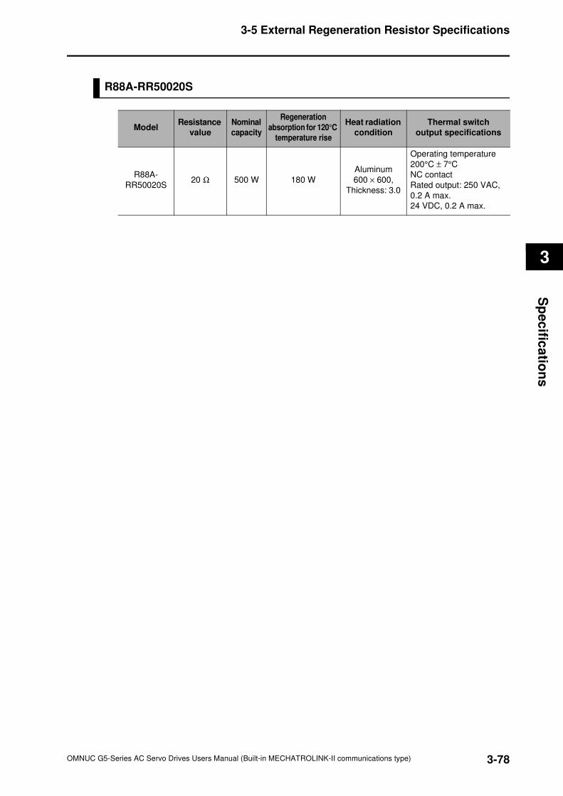
3-78
3-5 External Regeneration Resistor Specifications
OMNUC G5-Series AC Servo Drives Users Manual (Built-in MECHATROLINK-II communications type)
3
Sp
ec
ifica
tion
s
R88A-RR50020S
ModelResistance
value
Nominal
capacity
Regeneration
absorption for 120°C
temperature rise
Heat radiation
condition
Thermal switch
output specifications
R88A-
RR50020S20 Ω 500 W 180 W
Aluminum
600 × 600,
Thickness: 3.0
Operating temperature
200°C ± 7°C
NC contact
Rated output: 250 VAC,
0.2 A max.
24 VDC, 0.2 A max.
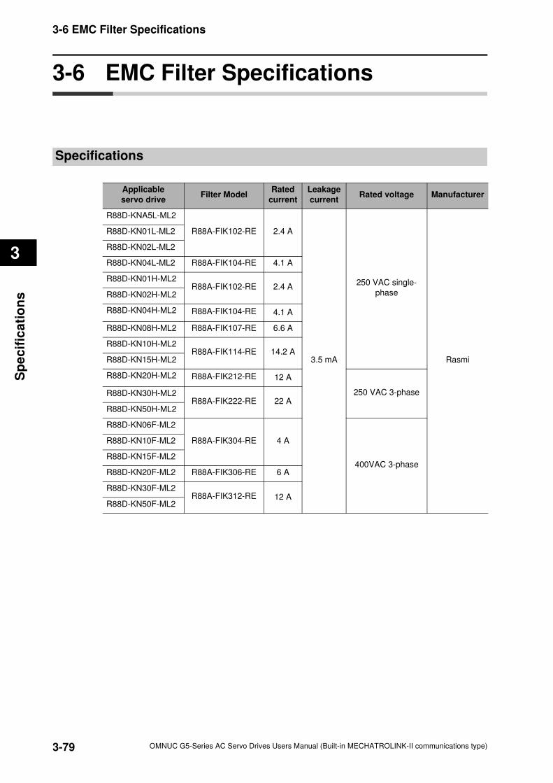
3-79
3-6 EMC Filter Specifications
OMNUC G5-Series AC Servo Drives Users Manual (Built-in MECHATROLINK-II communications type)
3
Sp
ecif
ica
tio
ns
3-6 EMC Filter Specifications
Specifications
Applicable
servo driveFilter Model
Rated
current
Leakage
currentRated voltage Manufacturer
R88D-KNA5L-ML2
R88A-FIK102-RE 2.4 A
3.5 mA
250 VAC single-
phase
Rasmi
R88D-KN01L-ML2
R88D-KN02L-ML2
R88D-KN04L-ML2 R88A-FIK104-RE 4.1 A
R88D-KN01H-ML2R88A-FIK102-RE 2.4 A
R88D-KN02H-ML2
R88D-KN04H-ML2 R88A-FIK104-RE 4.1 A
R88D-KN08H-ML2 R88A-FIK107-RE 6.6 A
R88D-KN10H-ML2R88A-FIK114-RE 14.2 A
R88D-KN15H-ML2
R88D-KN20H-ML2 R88A-FIK212-RE 12 A
250 VAC 3-phaseR88D-KN30H-ML2R88A-FIK222-RE 22 A
R88D-KN50H-ML2
R88D-KN06F-ML2
R88A-FIK304-RE 4 A
400VAC 3-phase
R88D-KN10F-ML2
R88D-KN15F-ML2
R88D-KN20F-ML2 R88A-FIK306-RE 6 A
R88D-KN30F-ML2R88A-FIK312-RE 12 A
R88D-KN50F-ML2
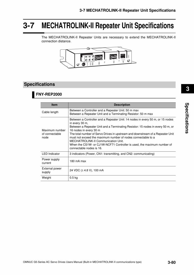
3-80
3-7 MECHATROLINK-II Repeater Unit Specifications
OMNUC G5-Series AC Servo Drives Users Manual (Built-in MECHATROLINK-II communications type)
3
Sp
ec
ifica
tion
s
3-7 MECHATROLINK-II Repeater Unit Specifications
The MECHATROLINK-II Repeater Units are necessary to extend the MECHATROLINK-II
connection distance.
Specifications
FNY-REP2000
Item Description
Cable lengthBetween a Controller and a Repeater Unit: 50 m max
Between a Repeater Unit and a Terminating Resistor: 50 m max
Maximum number
of connectable
node
Between a Controller and a Repeater Unit: 14 nodes in every 50 m, or 15 nodes
in every 30 m,
Between a Repeater Unit and a Terminating Resistor: 15 nodes in every 50 m, or
16 nodes in every 30 m
The total number of Servo Drives in upstream and downstream of a Repeater Unit
must not exceed the maximum number of nodes connectable to a
MECHATROLINK-II Communication Unit.
When the CS1W- or CJ1W-NCF71 Controller is used, the maximum number of
connectable nodes is 16.
LED Indicator 3 indicators (Power, CN1: transmitting, and CN2: communicating)
Power supply
current 180 mA max
External power
supply24 VDC (± 4.8 V), 100 mA
Weight 0.5 kg
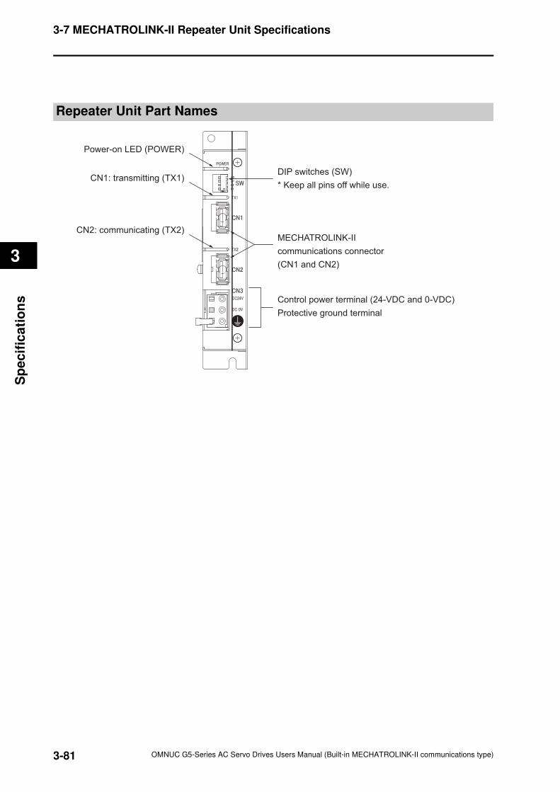
3-81
3-7 MECHATROLINK-II Repeater Unit Specifications
OMNUC G5-Series AC Servo Drives Users Manual (Built-in MECHATROLINK-II communications type)
3
Sp
ecif
ica
tio
ns
Repeater Unit Part Names
Power-on LED (POWER)
CN1: transmitting (TX1)
CN2: communicating (TX2)
DIP switches (SW)
* Keep all pins off while use.
MECHATROLINK-II
communications connector
(CN1 and CN2)
Control power terminal (24-VDC and 0-VDC)
Protective ground terminal
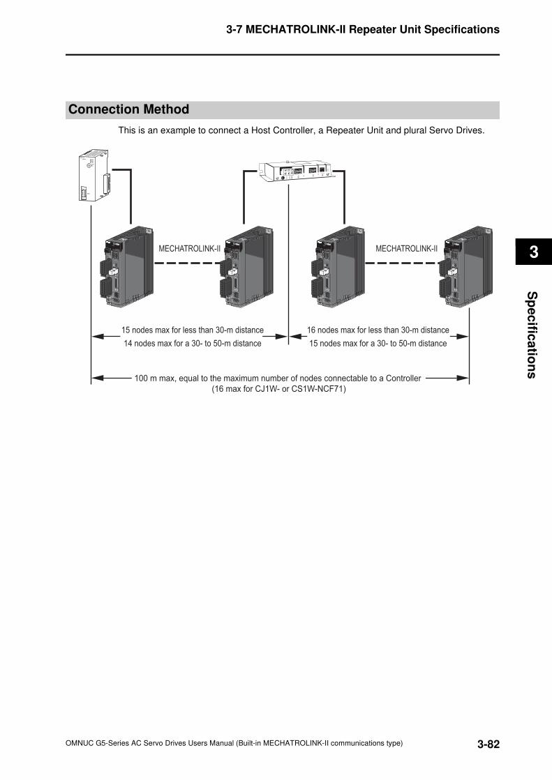
3-82
3-7 MECHATROLINK-II Repeater Unit Specifications
OMNUC G5-Series AC Servo Drives Users Manual (Built-in MECHATROLINK-II communications type)
3
Sp
ec
ifica
tion
s
Connection Method
This is an example to connect a Host Controller, a Repeater Unit and plural Servo Drives.
15 nodes max for less than 30-m distance
MECHATROLINK-II MECHATROLINK-II
14 nodes max for a 30- to 50-m distance
16 nodes max for less than 30-m distance
15 nodes max for a 30- to 50-m distance
100 m max, equal to the maximum number of nodes connectable to a Controller
(16 max for CJ1W- or CS1W-NCF71)
RUNERCERHERM
MLK
NCF71
UNITNo.
MLK
01234567
89A
BC
ML2A/B
ML2A/B
ML2A/B
ML2A/B
ML2A/B
ML2A/B
ML2A/B
ML2A/B

OMNUC G5-Series AC Servo Drives Users Manual (Built-in MECHATROLINK-II communications type)
4
4Accurax
This chapter explains the installation conditions, wiring methods including wiring
conforming to EMC directives and regenerative energy calculation methods
regarding the Servo Drive, Servomotor, as well as the performance of External
Regeneration Resistors, and so on.
4-1 Installation Conditions .................................................4-1
4-2 Wiring.............................................................................4-7
4-3 Wiring Conforming to EMC Directives......................4-21
4-4 Regenerative Energy Absorption..............................4-40
System Design
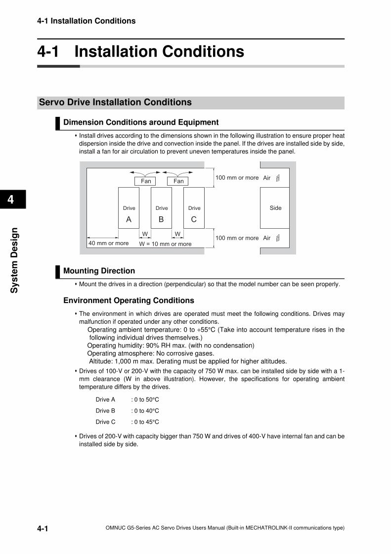
4-1 Installation Conditions
4
Sy
ste
m D
es
ign
4-1 Installation Conditions
Servo Drive Installation Conditions
Dimension Conditions around Equipment
Install drives according to the dimensions shown in the following illustration to ensure proper heat
dispersion inside the drive and convection inside the panel. If the drives are installed side by side,
install a fan for air circulation to prevent uneven temperatures inside the panel.
Mounting Direction
Mount the drives in a direction (perpendicular) so that the model number can be seen properly.
Environment Operating Conditions
The environment in which drives are operated must meet the following conditions. Drives may
malfunction if operated under any other conditions.
Operating ambient temperature: 0 to +55°C (Take into account temperature rises in the
following individual drives themselves.)
Operating humidity: 90% RH max. (with no condensation)
Operating atmosphere: No corrosive gases.
Altitude: 1,000 m max. Derating must be applied for higher altitudes.
Drives of 100-V or 200-V with the capacity of 750 W max. can be installed side by side with a 1-
mm clearance (W in above illustration). However, the specifications for operating ambient
temperature differs by the drives.
Drives of 200-V with capacity bigger than 750 W and drives of 400-V have internal fan and can be
installed side by side.
Drive A : 0 to 50°C
Drive B : 0 to 40°C
Drive C : 0 to 45°C
WW
Side
A B C
Drive Drive Drive
40 mm or more100 mm or more
Air
Air
Fan Fan
W = 10 mm or more
100 mm or more
4-1 OMNUC G5-Series AC Servo Drives Users Manual (Built-in MECHATROLINK-II communications type)
4-1 Installation Conditions
4
Sy
ste
m D
es
ign
Ambient Temperature Control
To operate in environments in which there is minimal temperature rise is recommended to
maintain a high level of reliability.
When the drive is installed in a closed space, such as a box, ambient temperature may rise due
to temperature rise in each unit. Use a fan or air conditioner to prevent the drive's ambient
temperature from exceeding 55°C.
Drive surface temperatures may rise to as much as 30°C above the ambient temperature. Use
heat-resistant materials for wiring, and keep its distance from any devices or wiring that are
sensitive to heat.
The service life of a Servo Drive is largely determined by the ambient temperature around the
internal electrolytic capacitors. When an electrolytic capacitor reaches its limit, electrostatic
capacity drops and internal resistance increases. This leads to overvoltage alarms, malfunctioning
due to noise, and damage to individual elements.
If a drive is always operated at the ambient temperature of 55°C and with 100% output of the rated
torque and rated rotation speed, its limit is expected to be approx. 28,000 hours (excluding the
axial-flow fan). A drop of 10°C in the ambient temperature will double the expected limit for drive.
Keeping Foreign Objects Out of Units
Place a cover over the drive or take other preventative measures to prevent foreign objects, such
as drill filings, from getting into the drive during installation. Be sure to remove the cover after
installation is complete. If the cover is left on during operation, drive's heat dissipation is blocked,
which may result in malfunction.
Take measures during installation and operation to prevent foreign objects such as metal
particles, oil, machining oil, dust, or water from getting inside of drives.
Lifetime 25°C = Lifetim 55°C × 2 = 224000 hour10
55−25
4-2OMNUC G5-Series AC Servo Drives Users Manual (Built-in MECHATROLINK-II communications type)
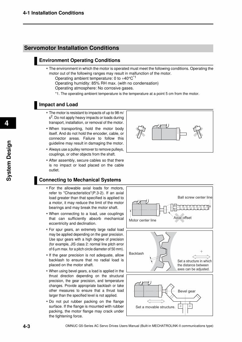
4-1 Installation Conditions
4
Sy
ste
m D
es
ign
Servomotor Installation Conditions
Environment Operating Conditions
The environment in which the motor is operated must meet the following conditions. Operating the
motor out of the following ranges may result in malfunction of the motor.
Operating ambient temperature: 0 to +40°C*1
Operating humidity: 85% RH max. (with no condensation)
Operating atmosphere: No corrosive gases.
*1. The operating ambient temperature is the temperature at a point 5 cm from the motor.
Impact and Load
The motor is resistant to impacts of up to 98 m/
s2. Do not apply heavy impacts or loads during
transport, installation, or removal of the motor.
When transporting, hold the motor body
itself. And do not hold the encoder, cable, or
connector areas. Failure to follow this
guideline may result in damaging the motor.
Always use a pulley remover to remove pulleys,
couplings, or other objects from the shaft.
After assembly, secure cables so that there
is no impact or load placed on the cable
outlet.
Connecting to Mechanical Systems
For the allowable axial loads for motors,
refer to "Characteristics"(P.3-2). If an axial
load greater than that specified is applied to
a motor, it may reduce the limit of the motor
bearings and may break the motor shaft.
When connecting to a load, use couplings
that can sufficiently absorb mechanical
eccentricity and declination.
For spur gears, an extremely large radial load
may be applied depending on the gear precision.
Use spur gears with a high degree of precision
(for example, JIS class 2: normal line pitch error
of 6 µm max. for a pitch circle diameter of 50 mm).
If the gear precision is not adequate, allow
backlash to ensure that no radial load is
placed on the motor shaft.
When using bevel gears, a load is applied in the
thrust direction depending on the structural
precision, the gear precision, and temperature
changes. Provide appropriate backlash or take
other measures to ensure that a thrust load
larger than the specified level is not applied.
Do not put rubber packing on the flange
surface. If the flange is mounted with rubber
packing, the motor flange may crack under
the tightening force.
Set a movable structure.
Bevel gear
Set a structure in whichthe distance betweenaxes can be adjusted.
Backlash
Motor center line
Ball screw center line
Axial offsetAxial offset
4-3 OMNUC G5-Series AC Servo Drives Users Manual (Built-in MECHATROLINK-II communications type)
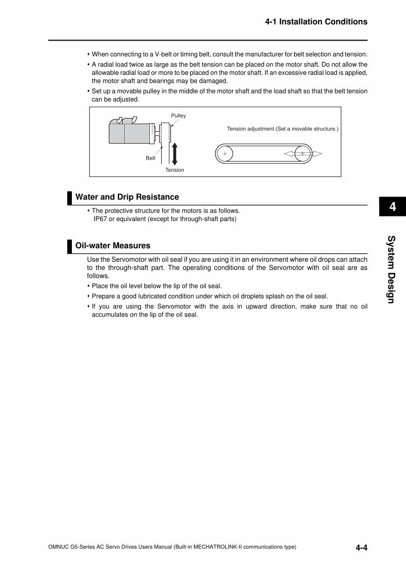
4-1 Installation Conditions
4
Sy
ste
m D
es
ign
When connecting to a V-belt or timing belt, consult the manufacturer for belt selection and tension.
A radial load twice as large as the belt tension can be placed on the motor shaft. Do not allow the
allowable radial load or more to be placed on the motor shaft. If an excessive radial load is applied,
the motor shaft and bearings may be damaged.
Set up a movable pulley in the middle of the motor shaft and the load shaft so that the belt tension
can be adjusted.
Water and Drip Resistance
The protective structure for the motors is as follows.
IP67 or equivalent (except for through-shaft parts)
Oil-water Measures
Use the Servomotor with oil seal if you are using it in an environment where oil drops can attach
to the through-shaft part. The operating conditions of the Servomotor with oil seal are as
follows.
Place the oil level below the lip of the oil seal.
Prepare a good lubricated condition under which oil droplets splash on the oil seal.
If you are using the Servomotor with the axis in upward direction, make sure that no oil
accumulates on the lip of the oil seal.
Pulley
Belt
Tension
Tension adjustment (Set a movable structure.)
4-4OMNUC G5-Series AC Servo Drives Users Manual (Built-in MECHATROLINK-II communications type)
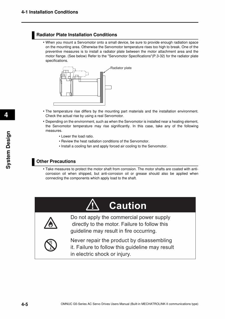
4-1 Installation Conditions
4
Sy
ste
m D
es
ign
Radiator Plate Installation Conditions
When you mount a Servomotor onto a small device, be sure to provide enough radiation space
on the mounting area. Otherwise the Servomotor temperature rises too high to break. One of the
preventive measures is to install a radiator plate between the motor attachment area and the
motor flange. (See below) Refer to the "Servomotor Specifications"(P.3-32) for the radiator plate
specifications.
The temperature rise differs by the mounting part materials and the installation environment.
Check the actual rise by using a real Servomotor.
Depending on the environment, such as when the Servomotor is installed near a heating element,
the Servomotor temperature may rise significantly. In this case, take any of the following
measures.
• Lower the load ratio.
• Review the heat radiation conditions of the Servomotor.
• Install a cooling fan and apply forced air cooling to the Servomotor.
Other Precautions
Take measures to protect the motor shaft from corrosion. The motor shafts are coated with anti-
corrosion oil when shipped, but anti-corrosion oil or grease should also be applied when
connecting the components which apply load to the shaft.
Radiator plate
Caution
Never repair the product by disassembling
it. Failure to follow this guideline may result
in electric shock or injury.
Do not apply the commercial power supply
directly to the motor. Failure to follow this
guideline may result in fire occurring.
4-5 OMNUC G5-Series AC Servo Drives Users Manual (Built-in MECHATROLINK-II communications type)
4-1 Installation Conditions
4
Sy
ste
m D
es
ign
Decelerator Installation Conditions
Using Another Company's Decelerator (Reference)
If the system configuration requires another company's decelerator to be used in combination
with an Accurax G5-Series motor, select the decelerator so that the load on the motor shaft
(i.e., both the radial and thrust loads) is within the allowable range. (Refer to
"Characteristics"(P.3-2) for details on the allowable loads for the motors.)
Also, select the decelerator so that the allowable input rotation speed and allowable input
torque of the decelerator are not exceeded.
4-6OMNUC G5-Series AC Servo Drives Users Manual (Built-in MECHATROLINK-II communications type)
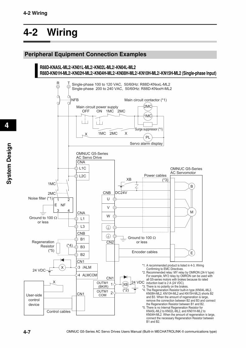
4-2 Wiring
4
Sy
ste
m D
es
ign
4-2 Wiring
Peripheral Equipment Connection Examples
R88D-KNA5L-ML2/-KN01L-ML2/-KN02L-ML2/-KN04L-ML2R88D-KN01H-ML2/-KN02H-ML2/-KN04H-ML2/-KN08H-ML2/-KN10H-ML2/-KN15H-ML2 (Single-phase Input)
R T
NFB
Noise filter (*1) 1 2
3 4
E NF
Ground to 100 Ωor less
Single-phase 100 to 120 VAC, 50/60Hz: R88D-KNxxL-ML2Single-phase 200 to 240 VAC, 50/60Hz: R88D-KNxxH-ML2
Main circuit contactor (*1)
1MC
PL
Surge suppressor (*1)
Servo alarm display
L1C
L2C
L1
L3
OMNUC G5-SeriesAC Servo Drive
2MC
ALMCOM
/ALM3
4
User-side
control
device
CN1
X24 VDC
1
2
OUTM1(BKIR)
OUTM1COM
XB24 VDC
Control cables
OMNUC G5-SeriesAC Servomotor
W
V
U
B
E
M
CN2
Ground to 100 Ωor less
Encoder cables
Power cables
DC24V
XB
*1. A recommended product is listed in 4-3, Wiring Confirming to EMC Directives.
*2. Recommended relay: MY relay by OMRON (24-V type) For example, MY2 relay by OMRON can be used with all G5-series motors with brakes because its rated induction load is 2 A (24 VDC).
*3. There is no polarity on the brakes.*4. The Regeneration Resistor built-in type (KN04L-ML2,
KN08H-ML2, KN10H-ML2 and KN15H-ML2) shorts B2 and B3. When the amount of regeneration is large, remove the connection between B2 and B3 and connect the Regeneration Resistor between B1 and B2.
*5. There is no Internal Regeneration Resistor for KNA5L-ML2 to KN02L-ML2, and KN01H-ML2 to KN04H-ML2. When the amount of regeneration is large, connect the necessary Regeneration Resistor between B1 and B2.
(*3)
(*2)
CN1
CN1
B1
B3
B2
(*4)Regeneration
Resistor(*5)
CNB
CNB
CNA
CNA
OFF
X
ON
1MC X
X
Main circuit power supply
2MC
1MC 2MC
2MC
1MC
4-7 OMNUC G5-Series AC Servo Drives Users Manual (Built-in MECHATROLINK-II communications type)
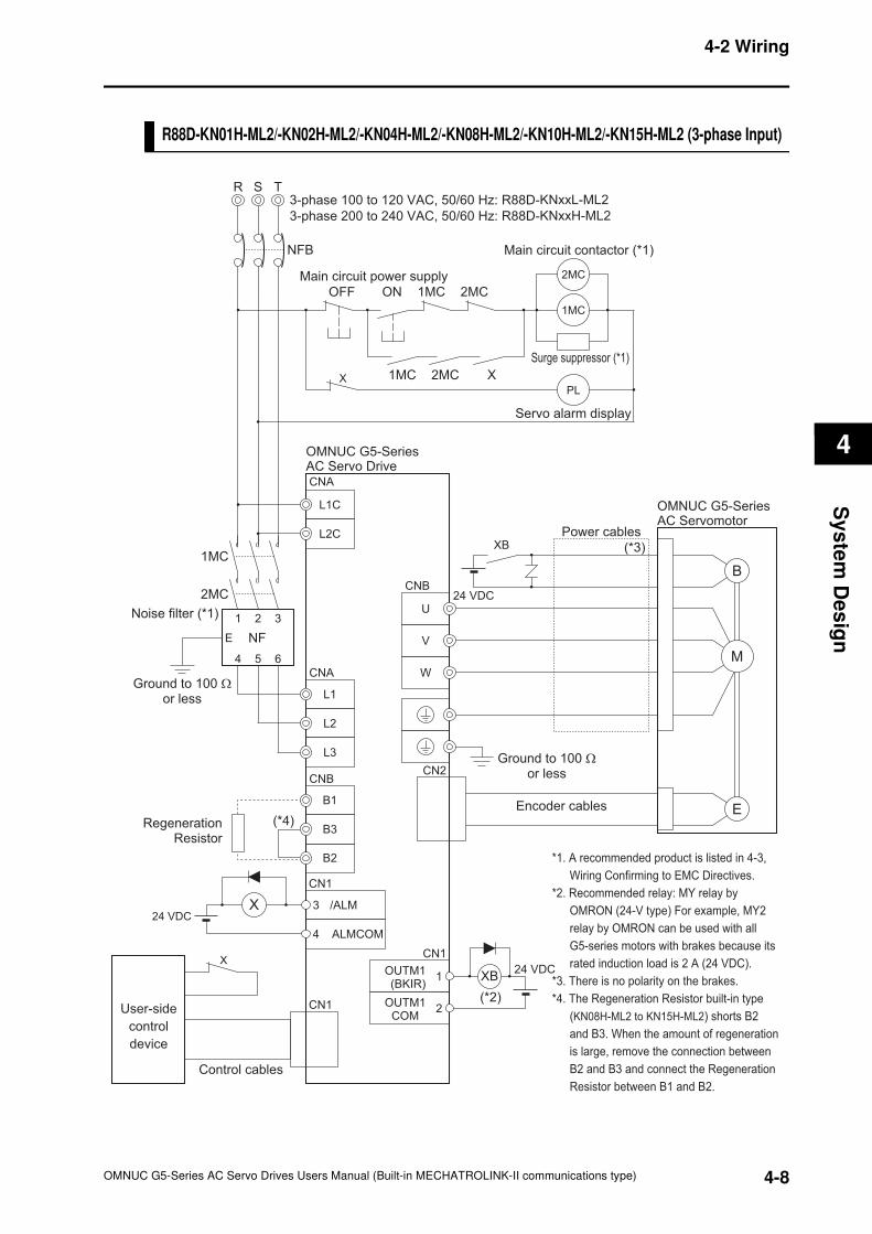
4-2 Wiring
4
Sy
ste
m D
es
ign
R88D-KN01H-ML2/-KN02H-ML2/-KN04H-ML2/-KN08H-ML2/-KN10H-ML2/-KN15H-ML2 (3-phase Input)
R T
NFB
S
Noise filter (*1) 1 2 3
4 5 6
E NF
Ground to 100 Ωor less
3-phase 100 to 120 VAC, 50/60 Hz: R88D-KNxxL-ML2
3-phase 200 to 240 VAC, 50/60 Hz: R88D-KNxxH-ML2
Main circuit contactor (*1)
PL
Servo alarm display
L1C
L2C
L1
L2
L3
OMNUC G5-SeriesAC Servo Drive
ALMCOM
/ALM3
4
User-side
control
device
CN1
X24 VDC
1
2
OUTM1(BKIR)
OUTM1COM
XB24 VDC
Control cables
OMNUC G5-SeriesAC Servomotor
W
V
U
B
E
M
CN2
Encoder cables
Power cables
24 VDC
(*3)
(*2)
CN1
CN1
*1. A recommended product is listed in 4-3,
Wiring Confirming to EMC Directives.
*2. Recommended relay: MY relay by
OMRON (24-V type) For example, MY2
relay by OMRON can be used with all
G5-series motors with brakes because its
rated induction load is 2 A (24 VDC).
*3. There is no polarity on the brakes.
*4. The Regeneration Resistor built-in type
(KN08H-ML2 to KN15H-ML2) shorts B2
and B3. When the amount of regeneration
is large, remove the connection between
B2 and B3 and connect the Regeneration
Resistor between B1 and B2.
B1
B3
B2
(*4)RegenerationResistor
CNB
CNB
CNA
CNA
Ground to 100 Ωor less
X
XB
2MC
X
1MC
Surge suppressor (*1)
OFF ON
1MC X
Main circuit power supply
2MC
1MC 2MC
2MC
1MC
4-8OMNUC G5-Series AC Servo Drives Users Manual (Built-in MECHATROLINK-II communications type)
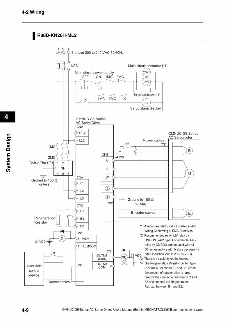
4-2 Wiring
4
Sy
ste
m D
es
ign
R88D-KN20H-ML2
R T
NFB
S
Noise filter (*1) 1 2 3
4 5 6
E NF
Ground to 100 Ωor less
3-phase 200 to 240 VAC 50/60Hz
Main circuit contactor (*1)
PL
Servo alarm display
L1C
L2C
L1
L2
L3
OMNUC G5-SeriesAC Servo Drive
ALMCOM
/ALM3
4
User-side
control
device
CN1
X24 VDC
1
2
OUTM1(BKIR)
OUTM1COM
XB24 VDC
Control cables
OMNUC G5-SeriesAC Servomotor
W
V
U
B
E
M
CN2
Encoder cables
Power cables
24 VDC
(*3)
(*2)
CN1
CN1
*1. A recommended product is listed in 4-3,
Wiring Confirming to EMC Directives.
*2. Recommended relay: MY relay by
OMRON (24-V type) For example, MY2
relay by OMRON can be used with all
G5-series motors with brakes because its
rated induction load is 2 A (24 VDC).
*3. There is no polarity on the brakes.
*4. The Regeneration Resistor built-in type
(KN20H-ML2) shorts B2 and B3. When
the amount of regeneration is large,
remove the connection between B2 and
B3 and connect the Regeneration
Resistor between B1 and B2.
B1
B3
B2
(*4)Regeneration
Resistor
CNB
CNC
CNA
CNA
Ground to 100 Ωor less
X
XB
2MC
X
1MC
Surge suppressor (*1)
OFF ON
1MC X
Main circuit power supply
2MC
1MC 2MC
2MC
1MC
4-9 OMNUC G5-Series AC Servo Drives Users Manual (Built-in MECHATROLINK-II communications type)
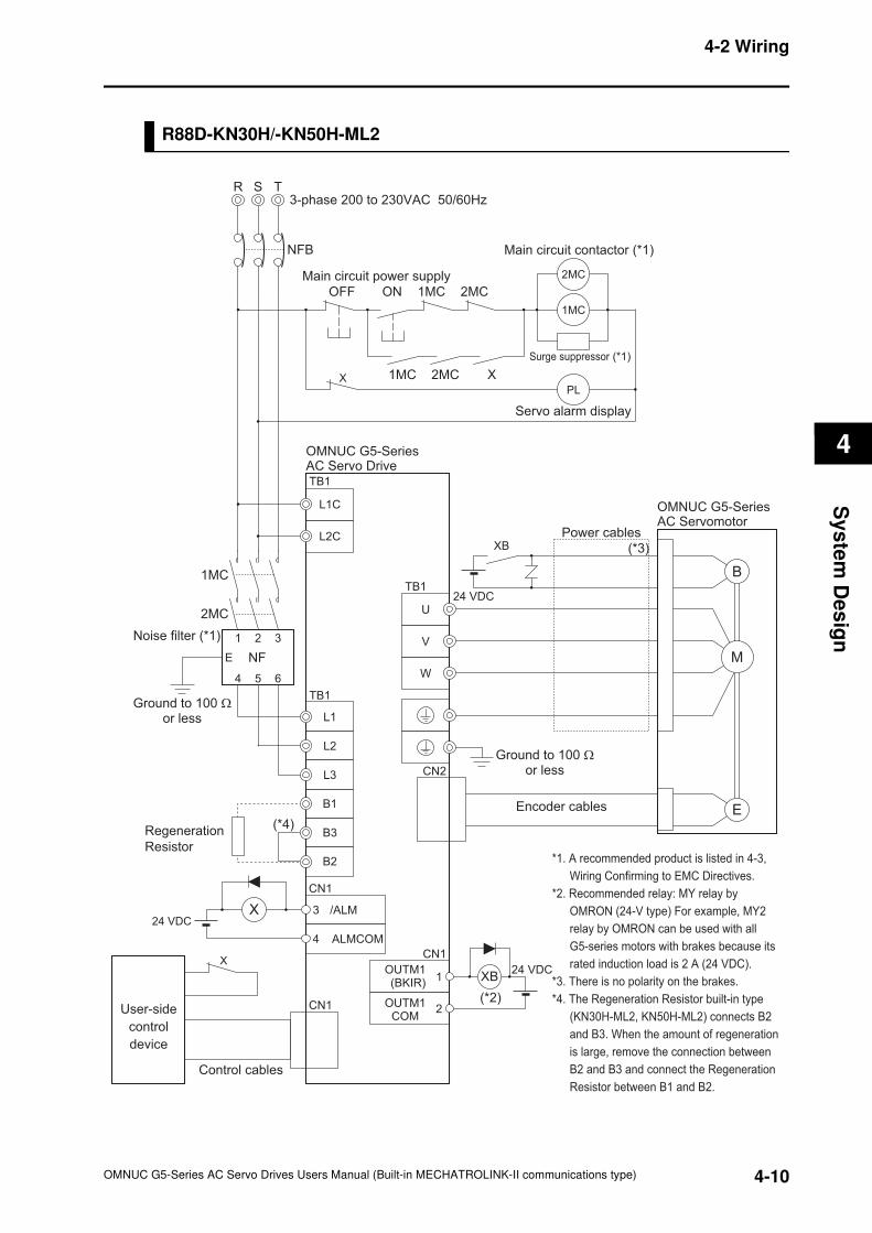
4-2 Wiring
4
Sy
ste
m D
es
ign
R88D-KN30H/-KN50H-ML2
R T
NFB
S
Noise filter (*1) 1 2 3
4 5 6
E NF
Ground to 100 Ωor less
3-phase 200 to 230VAC 50/60Hz
PL
Servo alarm display
L1C
L2C
L1
L2
L3
OMNUC G5-SeriesAC Servo Drive
ALMCOM
/ALM3
4
User-side
control
device
CN1
X24 VDC
1
2
OUTM1(BKIR)
OUTM1COM
XB24 VDC
Control cables
OMNUC G5-SeriesAC Servomotor
W
V
U
B
E
M
CN2
Encoder cables
Power cables
24 VDC
(*3)
(*2)
CN1
CN1
*1. A recommended product is listed in 4-3,
Wiring Confirming to EMC Directives.
*2. Recommended relay: MY relay by
OMRON (24-V type) For example, MY2
relay by OMRON can be used with all
G5-series motors with brakes because its
rated induction load is 2 A (24 VDC).
*3. There is no polarity on the brakes.
*4. The Regeneration Resistor built-in type
(KN30H-ML2, KN50H-ML2) connects B2
and B3. When the amount of regeneration
is large, remove the connection between
B2 and B3 and connect the Regeneration
Resistor between B1 and B2.
B1
B3
B2
(*4)Regeneration
Resistor
TB1
TB1
TB1
Ground to 100 Ωor less
X
XB
2MC
X
Main circuit contactor (*1)
1MC
Surge suppressor (*1)
OFF ON
1MC X
Main circuit power supply
2MC
1MC 2MC
2MC
1MC
4-10OMNUC G5-Series AC Servo Drives Users Manual (Built-in MECHATROLINK-II communications type)
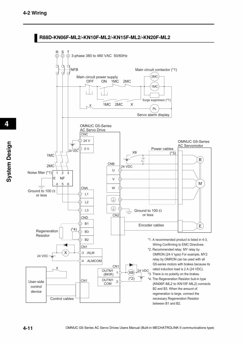
4-2 Wiring
4
Sy
ste
m D
es
ign
R88D-KN06F-ML2/-KN10F-ML2/-KN15F-ML2/-KN20F-ML2
R T
NFB
S
Noise filter (*1) 1 2 3
4 5 6
E NF
Ground to 100 Ωor less
3-phase 380 to 480 VAC 50/60Hz
Main circuit contactor (*1)
PL
Servo alarm display
24 V
24 VDC0 V
L1
L2
L3
OMNUC G5-SeriesAC Servo Drive
ALMCOM
/ALM3
4
User-side
control
device
CN1
X24 VDC
1
2
OUTM1(BKIR)
OUTM1COM
XB24 VDC
Control cables
OMNUC G5-SeriesAC Servomotor
W
V
U
B
E
M
CN2
Encoder cables
Power cables
24 VDC
(*3)
(*2)
CN1
CN1
*1. A recommended product is listed in 4-3,
Wiring Confirming to EMC Directives.
*2. Recommended relay: MY relay by
OMRON (24-V type) For example, MY2
relay by OMRON can be used with all
G5-series motors with brakes because its
rated induction load is 2 A (24 VDC).
*3. There is no polarity on the brakes.
*4. The Regeneration Resistor buit-in type
(KN06F-ML2 to KN15F-ML2) connects
B2 and B3. When the amount of
regeneration is large, connect the
necessary Regeneration Resistor
between B1 and B2.
B1
B3
B2
(*4)Regeneration
Resistor
CNB
CND
CNC
CNA
Ground to 100 Ωor less
X
XB
2MC
X
1MC
Surge suppressor (*1)
OFF ON
1MC X
Main circuit power supply
2MC
1MC 2MC
2MC
1MC
4-11 OMNUC G5-Series AC Servo Drives Users Manual (Built-in MECHATROLINK-II communications type)
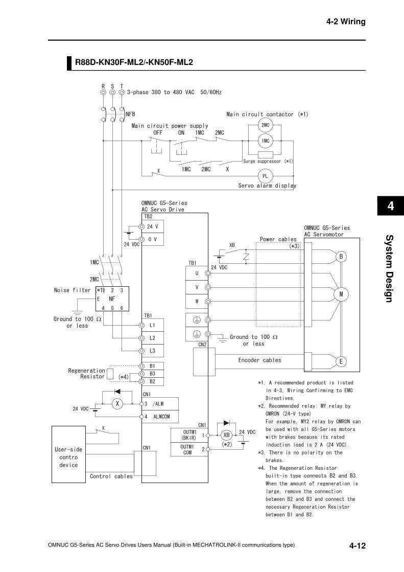
4-2 Wiring
4
Sy
ste
m D
es
ign
R88D-KN30F-ML2/-KN50F-ML2
Ω
Ω
4-12OMNUC G5-Series AC Servo Drives Users Manual (Built-in MECHATROLINK-II communications type)
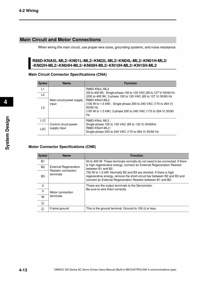
4-2 Wiring
4
Sy
ste
m D
es
ign
there
r
and
Main Circuit and Motor Connections
When wiring the main circuit, use proper wire sizes, grounding systems, and noise resistance.
R88D-KNA5L-ML2/-KN01L-ML2/-KN02L-ML2/-KN04L-ML2/-KN01H-ML2/-KN02H-ML2/-KN04H-ML2/-KN08H-ML2/-KN10H-ML2/-KN15H-ML2
Main Circuit Connector Specifications (CNA)
Motor Connector Specifications (CNB)
Symbol Name Function
L1
Main circuit power supply
input
R88D-KNxL-ML2
(50 to 400 W) : Single-phase 100 to 120 VAC (85 to 127 V) 50/60 Hz
(200 to 400 W): 3-phase 100 to 120 VAC (85 to 127 V) 50/60 Hz
R88D-KNxH-ML2
(100 W to 1.5 kW) : Single-phase 200 to 240 VAC (170 to 264 V)
50/60 Hz
(100 W to 1.5 kW): 3-phase 200 to 240 VAC (170 to 264 V) 50/60
Hz
L2
L3
L1C
Control circuit power
supply input
R88D-KNxL-ML2 :
Single-phase 100 to 120 VAC (85 to 132 V) 50/60Hz
R88D-KNxH-ML2 :
Single-phase 200 to 240 VAC (170 to 264 V) 50/60 HzL2C
Symbol Name Function
B1
External Regeneration
Resistor connection
terminals
50 to 400 W: These terminals normally do not need to be connected. If
is high regenerative energy, connect an External Regeneration Resisto
between B1 and B2.
750 W to 1.5 kW: Normally B2 and B3 are shorted. If there is high
regenerative energy, remove the short-circuit bar between B2 and B3
connect an External Regeneration Resistor between B1 and B2.
B2
B3
U
Motor connection
terminals
These are the output terminals to the Servomotor.
Be sure to wire them correctly.V
W
Frame ground This is the ground terminal. Ground to 100 Ω or less.
4-13 OMNUC G5-Series AC Servo Drives Users Manual (Built-in MECHATROLINK-II communications type)
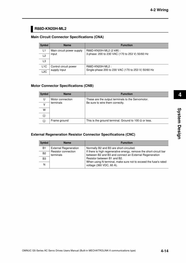
4-2 Wiring
4
Sy
ste
m D
es
ign
R88D-KN20H-ML2
Main Circuit Connector Specifications (CNA)
Motor Connector Specifications (CNB)
External Regeneration Resistor Connector Specifications (CNC)
Symbol Name Function
L1 Main circuit power supply
input
R88D-KN20H-ML2 (2 kW) :
3-phase: 200 to 230 VAC (170 to 253 V) 50/60 HzL2
L3
L1C Control circuit power
supply input
R88D-KN20H-ML2 :
Single-phase 200 to 230 VAC (170 to 253 V) 50/60 HzL2C
Symbol Name Function
U Motor connection
terminals
These are the output terminals to the Servomotor.
Be sure to wire them correctly.V
W
Frame ground This is the ground terminal. Ground to 100 Ω or less.
Symbol Name Function
B1 External Regeneration
Resistor connection
terminals
Normally B2 and B3 are short-circuited.
If there is high regenerative energy, remove the short-circuit bar
between B2 and B3 and connect an External Regeneration
Resistor between B1 and B2.
When using N terminal, make sure not to exceed the fuse's rated
voltage (360 VDC, 60 A).
B2
B3
N
4-14OMNUC G5-Series AC Servo Drives Users Manual (Built-in MECHATROLINK-II communications type)
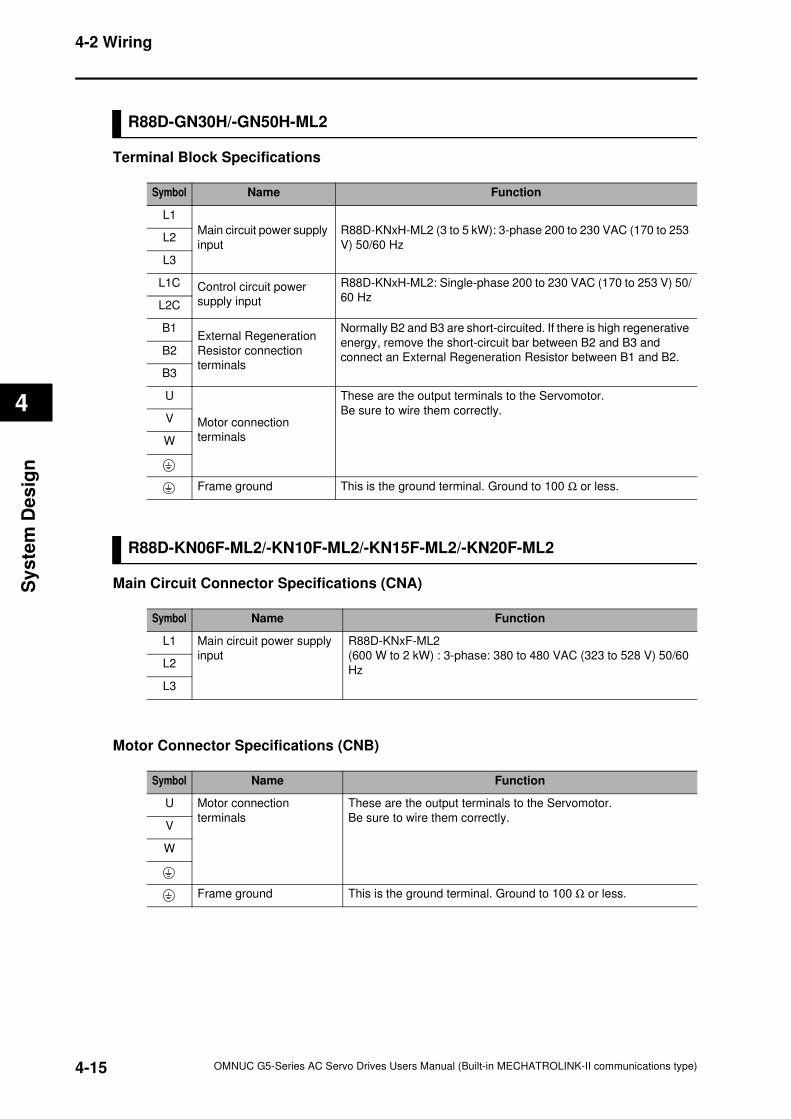
4-2 Wiring
4
Sy
ste
m D
es
ign
R88D-GN30H/-GN50H-ML2
Terminal Block Specifications
R88D-KN06F-ML2/-KN10F-ML2/-KN15F-ML2/-KN20F-ML2
Main Circuit Connector Specifications (CNA)
Motor Connector Specifications (CNB)
Symbol Name Function
L1
Main circuit power supply
input
R88D-KNxH-ML2 (3 to 5 kW): 3-phase 200 to 230 VAC (170 to 253
V) 50/60 HzL2
L3
L1C Control circuit power
supply input
R88D-KNxH-ML2: Single-phase 200 to 230 VAC (170 to 253 V) 50/
60 HzL2C
B1External Regeneration
Resistor connection
terminals
Normally B2 and B3 are short-circuited. If there is high regenerative
energy, remove the short-circuit bar between B2 and B3 and
connect an External Regeneration Resistor between B1 and B2.B2
B3
U
Motor connection
terminals
These are the output terminals to the Servomotor.
Be sure to wire them correctly.V
W
Frame ground This is the ground terminal. Ground to 100 Ω or less.
Symbol Name Function
L1 Main circuit power supply
input
R88D-KNxF-ML2
(600 W to 2 kW) : 3-phase: 380 to 480 VAC (323 to 528 V) 50/60
HzL2
L3
Symbol Name Function
U Motor connection
terminals
These are the output terminals to the Servomotor.
Be sure to wire them correctly.V
W
Frame ground This is the ground terminal. Ground to 100 Ω or less.
4-15 OMNUC G5-Series AC Servo Drives Users Manual (Built-in MECHATROLINK-II communications type)
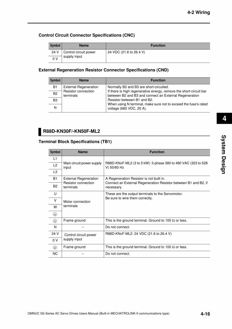
4-2 Wiring
4
Sy
ste
m D
es
ign
Control Circuit Connector Specifications (CNC)
External Regeneration Resistor Connector Specifications (CND)
R88D-KN30F/-KN50F-ML2
Terminal Block Specifications (TB1)
Symbol Name Function
24 V Control circuit power
supply input
24 VDC (21.6 to 26.4 V)
0 V
Symbol Name Function
B1 External Regeneration
Resistor connection
terminals
Normally B2 and B3 are short-circuited.
If there is high regenerative energy, remove the short-circuit bar
between B2 and B3 and connect an External Regeneration
Resistor between B1 and B2.
When using N terminal, make sure not to exceed the fuse's rated
voltage (660 VDC, 20 A).
B2
B3
N
Symbol Name Function
L1
Main circuit power supply
input
R88D-KNxF-ML2 (3 to 5 kW): 3-phase 380 to 480 VAC (323 to 528
V) 50/60 HzL2
L3
B1 External Regeneration
Resistor connection
terminals
A Regeneration Resistor is not built in.
Connect an External Regeneration Resistor between B1 and B2, if
necessary.B2
U
Motor connection
terminals
These are the output terminals to the Servomotor.
Be sure to wire them correctly.V
W
Frame ground This is the ground terminal. Ground to 100 Ω or less.
N − Do not connect.
24 V Control circuit power
supply input
R88D-KNxF-ML2: 24 VDC (21.6 to 26.4 V)
0 V
Frame ground This is the ground terminal. Ground to 100 Ω or less.
NC − Do not connect.
4-16OMNUC G5-Series AC Servo Drives Users Manual (Built-in MECHATROLINK-II communications type)
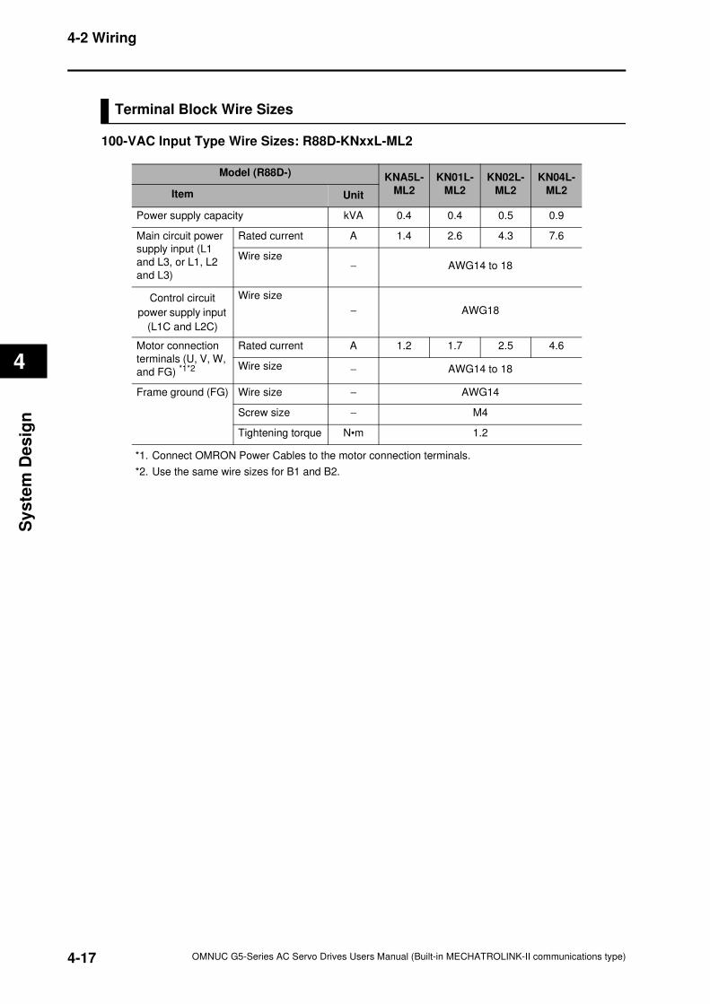
4-2 Wiring
4
Sy
ste
m D
es
ign
Terminal Block Wire Sizes
100-VAC Input Type Wire Sizes: R88D-KNxxL-ML2
*1. Connect OMRON Power Cables to the motor connection terminals.
*2. Use the same wire sizes for B1 and B2.
Model (R88D-) KNA5L-
ML2
KN01L-
ML2
KN02L-
ML2
KN04L-
ML2Item Unit
Power supply capacity kVA 0.4 0.4 0.5 0.9
Main circuit power
supply input (L1
and L3, or L1, L2
and L3)
Rated current A 1.4 2.6 4.3 7.6
Wire size− AWG14 to 18
Control circuit
power supply input
(L1C and L2C)
Wire size
− AWG18
Motor connection
terminals (U, V, W,
and FG) *1*2
Rated current A 1.2 1.7 2.5 4.6
Wire size − AWG14 to 18
Frame ground (FG) Wire size − AWG14
Screw size − M4
Tightening torque N•m 1.2
4-17 OMNUC G5-Series AC Servo Drives Users Manual (Built-in MECHATROLINK-II communications type)
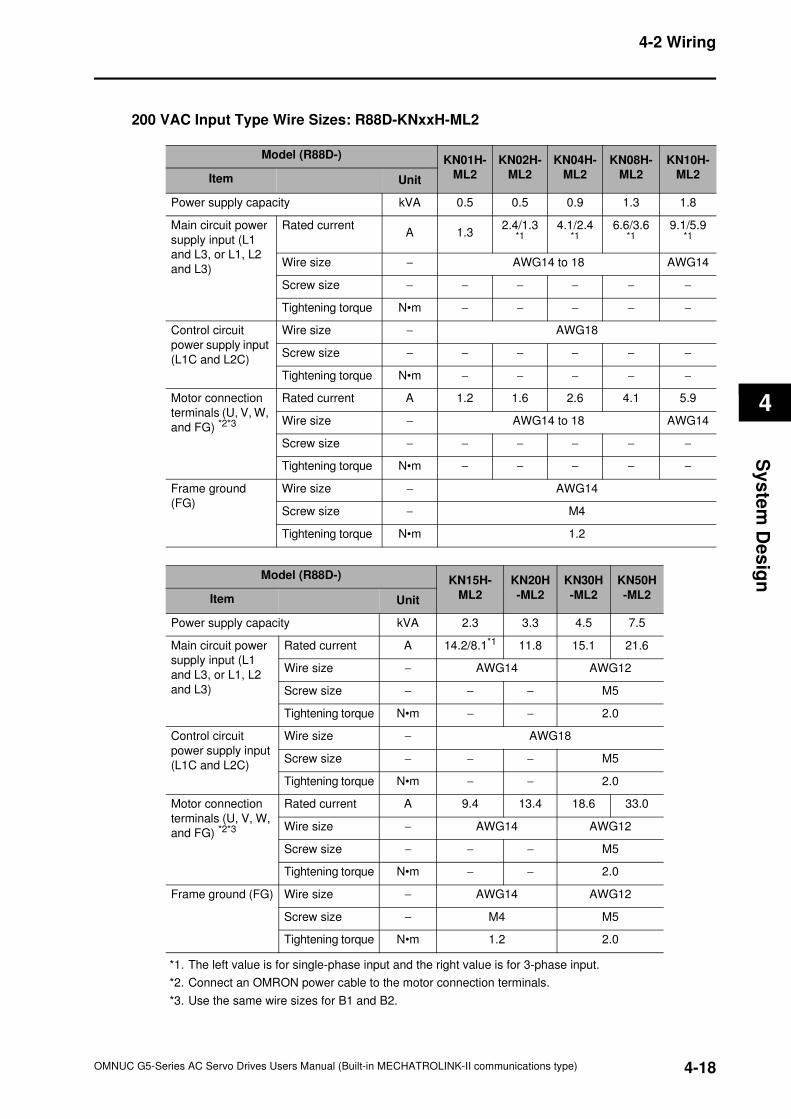
4-2 Wiring
4
Sy
ste
m D
es
ign
200 VAC Input Type Wire Sizes: R88D-KNxxH-ML2
*1. The left value is for single-phase input and the right value is for 3-phase input.
*2. Connect an OMRON power cable to the motor connection terminals.
*3. Use the same wire sizes for B1 and B2.
Model (R88D-) KN01H-
ML2
KN02H-
ML2
KN04H-
ML2
KN08H-
ML2
KN10H-
ML2Item Unit
Power supply capacity kVA 0.5 0.5 0.9 1.3 1.8
Main circuit power
supply input (L1
and L3, or L1, L2
and L3)
Rated currentA 1.3
2.4/1.3*1
4.1/2.4*1
6.6/3.6*1
9.1/5.9*1
Wire size − AWG14 to 18 AWG14
Screw size − − − − − −
Tightening torque N•m − − − − −
Control circuit
power supply input
(L1C and L2C)
Wire size − AWG18
Screw size − − − − − −
Tightening torque N•m − − − − −
Motor connection
terminals (U, V, W,
and FG) *2*3
Rated current A 1.2 1.6 2.6 4.1 5.9
Wire size − AWG14 to 18 AWG14
Screw size − − − − − −
Tightening torque N•m − − − − −
Frame ground
(FG)
Wire size − AWG14
Screw size − M4
Tightening torque N•m 1.2
Model (R88D-) KN15H-
ML2
KN20H
-ML2
KN30H
-ML2
KN50H
-ML2Item Unit
Power supply capacity kVA 2.3 3.3 4.5 7.5
Main circuit power
supply input (L1
and L3, or L1, L2
and L3)
Rated current A 14.2/8.1*1 11.8 15.1 21.6
Wire size − AWG14 AWG12
Screw size − − − M5
Tightening torque N•m − − 2.0
Control circuit
power supply input
(L1C and L2C)
Wire size − AWG18
Screw size − − − M5
Tightening torque N•m − − 2.0
Motor connection
terminals (U, V, W,
and FG) *2*3
Rated current A 9.4 13.4 18.6 33.0
Wire size − AWG14 AWG12
Screw size − − − M5
Tightening torque N•m − − 2.0
Frame ground (FG) Wire size − AWG14 AWG12
Screw size − M4 M5
Tightening torque N•m 1.2 2.0
4-18OMNUC G5-Series AC Servo Drives Users Manual (Built-in MECHATROLINK-II communications type)
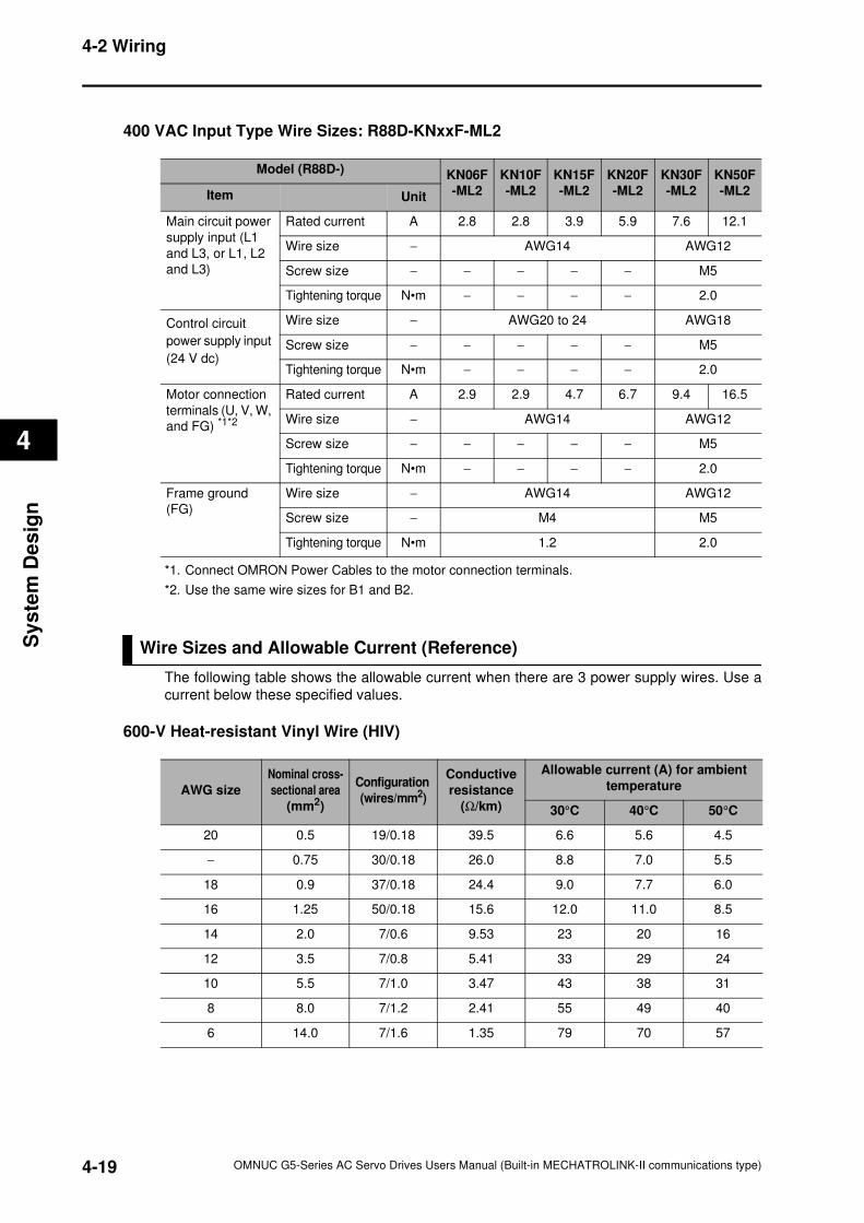
4-2 Wiring
4
Sy
ste
m D
es
ign
400 VAC Input Type Wire Sizes: R88D-KNxxF-ML2
*1. Connect OMRON Power Cables to the motor connection terminals.
*2. Use the same wire sizes for B1 and B2.
Wire Sizes and Allowable Current (Reference)
The following table shows the allowable current when there are 3 power supply wires. Use a
current below these specified values.
600-V Heat-resistant Vinyl Wire (HIV)
Model (R88D-) KN06F
-ML2
KN10F
-ML2
KN15F
-ML2
KN20F
-ML2
KN30F
-ML2
KN50F
-ML2Item Unit
Main circuit power
supply input (L1
and L3, or L1, L2
and L3)
Rated current A 2.8 2.8 3.9 5.9 7.6 12.1
Wire size − AWG14 AWG12
Screw size − − − − − M5
Tightening torque N•m − − − − 2.0
Control circuit
power supply input
(24 V dc)
Wire size − AWG20 to 24 AWG18
Screw size − − − − − M5
Tightening torque N•m − − − − 2.0
Motor connection
terminals (U, V, W,
and FG) *1*2
Rated current A 2.9 2.9 4.7 6.7 9.4 16.5
Wire size − AWG14 AWG12
Screw size − − − − − M5
Tightening torque N•m − − − − 2.0
Frame ground
(FG)
Wire size − AWG14 AWG12
Screw size − M4 M5
Tightening torque N•m 1.2 2.0
AWG size
Nominal cross-
sectional area
(mm2)
Configuration
(wires/mm2)
Conductive
resistance
(Ω/km)
Allowable current (A) for ambient
temperature
30°C 40°C 50°C
20 0.5 19/0.18 39.5 6.6 5.6 4.5
− 0.75 30/0.18 26.0 8.8 7.0 5.5
18 0.9 37/0.18 24.4 9.0 7.7 6.0
16 1.25 50/0.18 15.6 12.0 11.0 8.5
14 2.0 7/0.6 9.53 23 20 16
12 3.5 7/0.8 5.41 33 29 24
10 5.5 7/1.0 3.47 43 38 31
8 8.0 7/1.2 2.41 55 49 40
6 14.0 7/1.6 1.35 79 70 57
4-19 OMNUC G5-Series AC Servo Drives Users Manual (Built-in MECHATROLINK-II communications type)
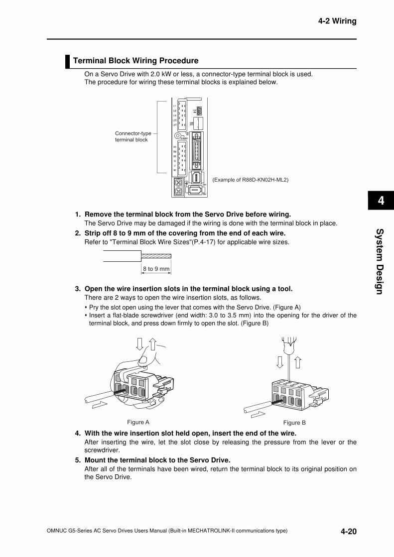
4-2 Wiring
4
Sy
ste
m D
es
ign
Terminal Block Wiring Procedure
On a Servo Drive with 2.0 kW or less, a connector-type terminal block is used.
The procedure for wiring these terminal blocks is explained below.
1. Remove the terminal block from the Servo Drive before wiring.
The Servo Drive may be damaged if the wiring is done with the terminal block in place.
2. Strip off 8 to 9 mm of the covering from the end of each wire.
Refer to "Terminal Block Wire Sizes"(P.4-17) for applicable wire sizes.
3. Open the wire insertion slots in the terminal block using a tool.
There are 2 ways to open the wire insertion slots, as follows.
Pry the slot open using the lever that comes with the Servo Drive. (Figure A)
Insert a flat-blade screwdriver (end width: 3.0 to 3.5 mm) into the opening for the driver of the
terminal block, and press down firmly to open the slot. (Figure B)
4. With the wire insertion slot held open, insert the end of the wire.
After inserting the wire, let the slot close by releasing the pressure from the lever or the
screwdriver.
5. Mount the terminal block to the Servo Drive.
After all of the terminals have been wired, return the terminal block to its original position on
the Servo Drive.
Connector-type
terminal block
(Example of R88D-KN02H-ML2)
8 to 9 mm
Figure A Figure B
4-20OMNUC G5-Series AC Servo Drives Users Manual (Built-in MECHATROLINK-II communications type)
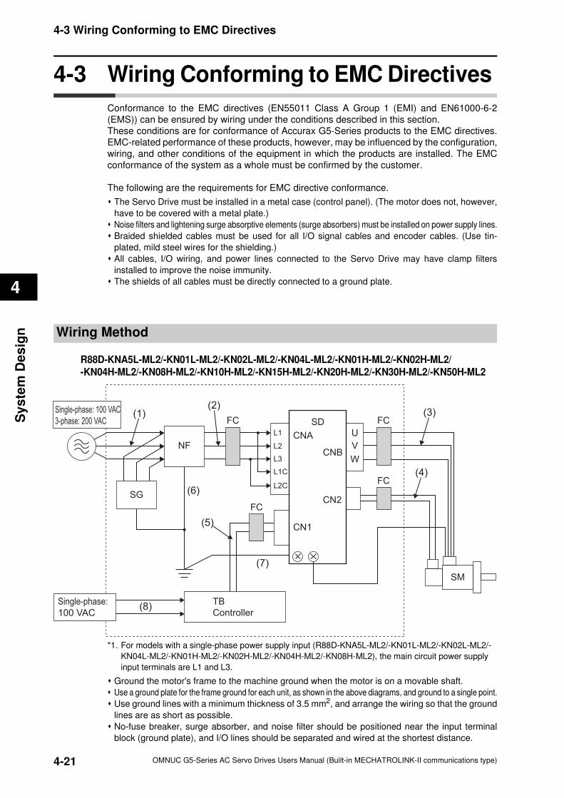
4-3 Wiring Conforming to EMC Directives
4
Sy
ste
m D
es
ign
4-3 Wiring Conforming to EMC Directives
Conformance to the EMC directives (EN55011 Class A Group 1 (EMI) and EN61000-6-2
(EMS)) can be ensured by wiring under the conditions described in this section.
These conditions are for conformance of Accurax G5-Series products to the EMC directives.
EMC-related performance of these products, however, may be influenced by the configuration,
wiring, and other conditions of the equipment in which the products are installed. The EMC
conformance of the system as a whole must be confirmed by the customer.
The following are the requirements for EMC directive conformance.
The Servo Drive must be installed in a metal case (control panel). (The motor does not, however,
have to be covered with a metal plate.)
Noise filters and lightening surge absorptive elements (surge absorbers) must be installed on power supply lines.
Braided shielded cables must be used for all I/O signal cables and encoder cables. (Use tin-
plated, mild steel wires for the shielding.)
All cables, I/O wiring, and power lines connected to the Servo Drive may have clamp filters
installed to improve the noise immunity.
The shields of all cables must be directly connected to a ground plate.
Wiring Method
R88D-KNA5L-ML2/-KN01L-ML2/-KN02L-ML2/-KN04L-ML2/-KN01H-ML2/-KN02H-ML2/-KN04H-ML2/-KN08H-ML2/-KN10H-ML2/-KN15H-ML2/-KN20H-ML2/-KN30H-ML2/-KN50H-ML2
*1. For models with a single-phase power supply input (R88D-KNA5L-ML2/-KN01L-ML2/-KN02L-ML2/-
KN04L-ML2/-KN01H-ML2/-KN02H-ML2/-KN04H-ML2/-KN08H-ML2), the main circuit power supply
input terminals are L1 and L3.
Ground the motor's frame to the machine ground when the motor is on a movable shaft.
Use a ground plate for the frame ground for each unit, as shown in the above diagrams, and ground to a single point.
Use ground lines with a minimum thickness of 3.5 mm2, and arrange the wiring so that the ground
lines are as short as possible.
No-fuse breaker, surge absorber, and noise filter should be positioned near the input terminal
block (ground plate), and I/O lines should be separated and wired at the shortest distance.
L1
L2
L3
L1C
L2C
Single-phase: 100 VAC
3-phase: 200 VAC
Single-phase:
100 VAC
SG
NF
FC FCSD
FC
FC
TB
Controller
CNA
CN1
CNB
CN2
U
V
W
SM
(3)
(4)
(1)(2)
(6)
(5)
(7)
(8)
4-21 OMNUC G5-Series AC Servo Drives Users Manual (Built-in MECHATROLINK-II communications type)
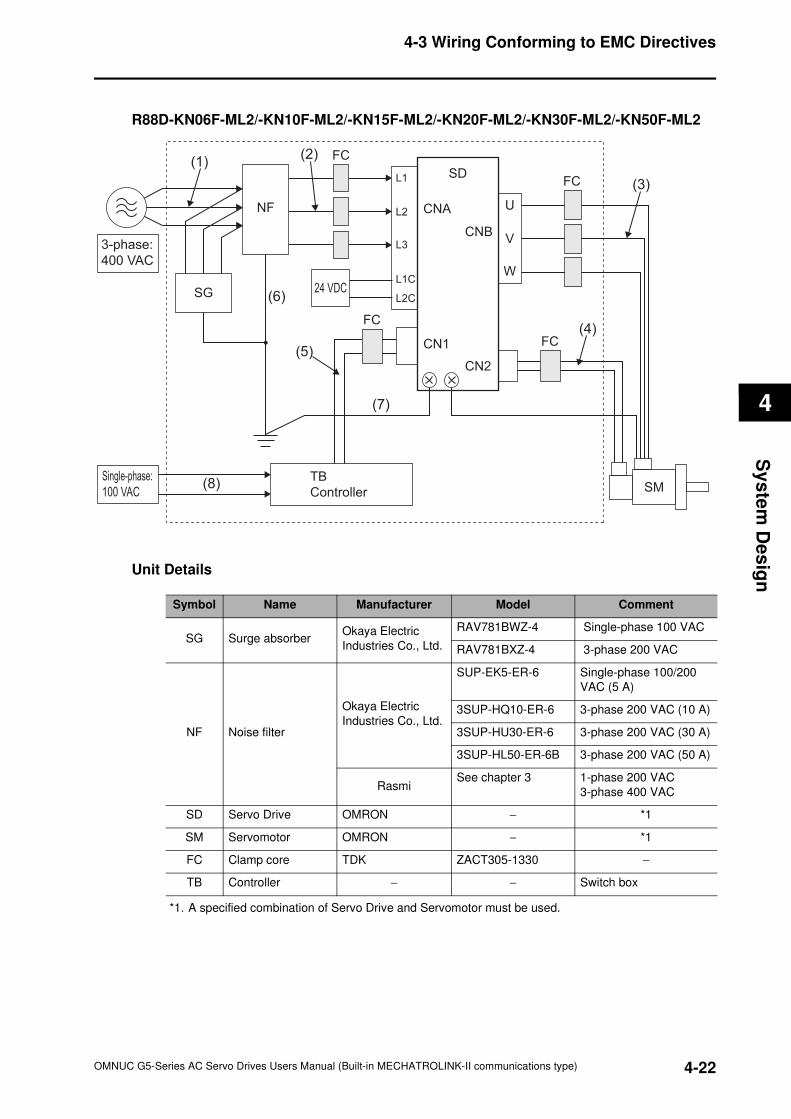
4-3 Wiring Conforming to EMC Directives
4
Sy
ste
m D
es
ign
R88D-KN06F-ML2/-KN10F-ML2/-KN15F-ML2/-KN20F-ML2/-KN30F-ML2/-KN50F-ML2
Unit Details
*1. A specified combination of Servo Drive and Servomotor must be used.
L1
L2
L3
L1C
L2C
Single-phase:
100 VAC
24 VDC
3-phase:
400 VAC
SG
NF
FC
FCSD
FC
FC
TB
Controller
CNA
CN1
CNB
CN2
U
V
W
SM
(3)
(4)
(1)(2)
(6)
(5)
(7)
(8)
Symbol Name Manufacturer Model Comment
SG Surge absorberOkaya Electric
Industries Co., Ltd.
RAV781BWZ-4 Single-phase 100 VAC
RAV781BXZ-4 3-phase 200 VAC
NF Noise filter
Okaya Electric
Industries Co., Ltd.
SUP-EK5-ER-6 Single-phase 100/200
VAC (5 A)
3SUP-HQ10-ER-6 3-phase 200 VAC (10 A)
3SUP-HU30-ER-6 3-phase 200 VAC (30 A)
3SUP-HL50-ER-6B 3-phase 200 VAC (50 A)
RasmiSee chapter 3 1-phase 200 VAC
3-phase 400 VAC
SD Servo Drive OMRON − *1
SM Servomotor OMRON − *1
FC Clamp core TDK ZACT305-1330 −
TB Controller − − Switch box
4-22OMNUC G5-Series AC Servo Drives Users Manual (Built-in MECHATROLINK-II communications type)
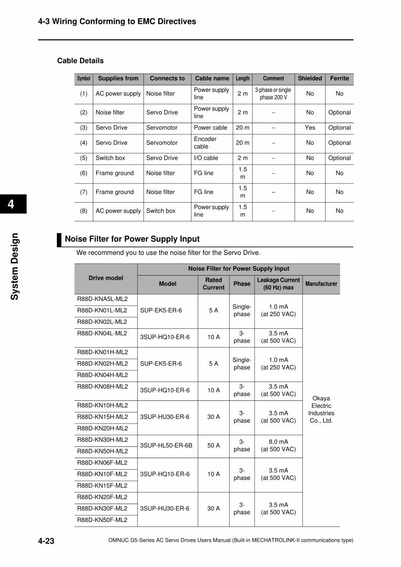
4-3 Wiring Conforming to EMC Directives
4
Sy
ste
m D
es
ign
Cable Details
Noise Filter for Power Supply Input
We recommend you to use the noise filter for the Servo Drive.
Symbol Supplies from Connects to Cable name Length Comment Shielded Ferrite
(1) AC power supply Noise filterPower supply
line2 m
3-phase or single
phase 200 VNo No
(2) Noise filter Servo DrivePower supply
line2 m − No Optional
(3) Servo Drive Servomotor Power cable 20 m − Yes Optional
(4) Servo Drive ServomotorEncoder
cable20 m − No Optional
(5) Switch box Servo Drive I/O cable 2 m − No Optional
(6) Frame ground Noise filter FG line1.5
m− No No
(7) Frame ground Noise filter FG line1.5
m− No No
(8) AC power supply Switch boxPower supply
line
1.5
m− No No
Drive model
Noise Filter for Power Supply Input
ModelRated
CurrentPhase
Leakage Current
(60 Hz) maxManufacturer
R88D-KNA5L-ML2
SUP-EK5-ER-6 5 ASingle-
phase
1.0 mA
(at 250 VAC)
Okaya
Electric
Industries
Co., Ltd.
R88D-KN01L-ML2
R88D-KN02L-ML2
R88D-KN04L-ML23SUP-HQ10-ER-6 10 A
3-
phase
3.5 mA
(at 500 VAC)
R88D-KN01H-ML2
SUP-EK5-ER-6 5 ASingle-
phase
1.0 mA
(at 250 VAC)R88D-KN02H-ML2
R88D-KN04H-ML2
R88D-KN08H-ML23SUP-HQ10-ER-6 10 A
3-
phase
3.5 mA
(at 500 VAC)
R88D-KN10H-ML2
3SUP-HU30-ER-6 30 A3-
phase
3.5 mA
(at 500 VAC)R88D-KN15H-ML2
R88D-KN20H-ML2
R88D-KN30H-ML23SUP-HL50-ER-6B 50 A
3-
phase
8.0 mA
(at 500 VAC)R88D-KN50H-ML2
R88D-KN06F-ML2
3SUP-HQ10-ER-6 10 A3-
phase
3.5 mA
(at 500 VAC)R88D-KN10F-ML2
R88D-KN15F-ML2
R88D-KN20F-ML2
3SUP-HU30-ER-6 30 A3-
phase
3.5 mA
(at 500 VAC)R88D-KN30F-ML2
R88D-KN50F-ML2
4-23 OMNUC G5-Series AC Servo Drives Users Manual (Built-in MECHATROLINK-II communications type)
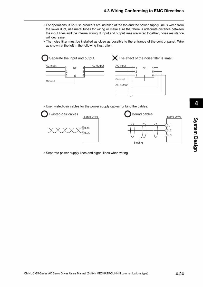
4-3 Wiring Conforming to EMC Directives
4
Sy
ste
m D
es
ign
For operations, if no-fuse breakers are installed at the top and the power supply line is wired from
the lower duct, use metal tubes for wiring or make sure that there is adequate distance between
the input lines and the internal wiring. If input and output lines are wired together, noise resistance
will decrease.
The noise filter must be installed as close as possible to the entrance of the control panel. Wire
as shown at the left in the following illustration.
Use twisted-pair cables for the power supply cables, or bind the cables.
Separate power supply lines and signal lines when wiring.
Separate the input and output. The effect of the noise filter is small.
NF1
2
3
4
5
6E
NF1
2
3
4
5
6E
AC input AC input
GroundGround
AC output
AC output
Twisted-pair cables Bound cablesServo Drive
L1CL1
L2
L3L2C
Servo Drive
Binding
4-24OMNUC G5-Series AC Servo Drives Users Manual (Built-in MECHATROLINK-II communications type)

4-3 Wiring Conforming to EMC Directives
4
Sy
ste
m D
es
ign
Control Panel Structure
Openings in the control panel, such as holes for cables, panel mounting holes, and gaps
around the door, may allow electromagnetic waves into the panel. To prevent this, observe the
recommendations described below when designing or selecting a control panel.
Case Structure
Use a metal control panel with welded joints at the top, bottom, and sides so that the surfaces are
electrically conductive.
If assembly is required, strip the paint off the joint areas (or mask them during painting), to make
them electrically conductive.
The panel may warp and gaps may appear when screws are tightened. Be sure that no gaps
appear when tightening screws.
Do not leave any conductive part unconnected.
Ground all units within the case to the case itself.
Door Structure
Use a metal door.
Use a water-draining structure where the door and case fit together, and leave no gaps. (Refer to
the diagrams.)
Use a conductive gasket between the door and the case. (Refer to the diagrams.)
Strip the paint off the sections of the door and case that will be in contact with the conductive
gasket (or mask them during painting), so that they are electrically conductive.
The panel may warp and gaps may appear when screws are tightened. Be sure that no gaps
appear when tightening screws.
Case
Door
[Control panel]
[Door (interior side)]
A
B
[A-B cross-section diagram]
Oil-resistant gasket
Conductive gasket
Door end
Oil-resistant gasket Conductive gasket
4-25 OMNUC G5-Series AC Servo Drives Users Manual (Built-in MECHATROLINK-II communications type)
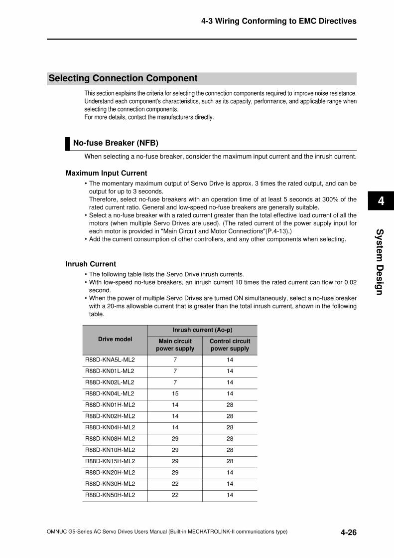
4-3 Wiring Conforming to EMC Directives
4
Sy
ste
m D
es
ign
Selecting Connection Component
This section explains the criteria for selecting the connection components required to improve noise resistance.
Understand each component's characteristics, such as its capacity, performance, and applicable range when
selecting the connection components.
For more details, contact the manufacturers directly.
No-fuse Breaker (NFB)
When selecting a no-fuse breaker, consider the maximum input current and the inrush current.
Maximum Input Current
The momentary maximum output of Servo Drive is approx. 3 times the rated output, and can be
output for up to 3 seconds.
Therefore, select no-fuse breakers with an operation time of at least 5 seconds at 300% of the
rated current ratio. General and low-speed no-fuse breakers are generally suitable.
Select a no-fuse breaker with a rated current greater than the total effective load current of all the
motors (when multiple Servo Drives are used). (The rated current of the power supply input for
each motor is provided in "Main Circuit and Motor Connections"(P.4-13).)
Add the current consumption of other controllers, and any other components when selecting.
Inrush Current
The following table lists the Servo Drive inrush currents.
With low-speed no-fuse breakers, an inrush current 10 times the rated current can flow for 0.02
second.
When the power of multiple Servo Drives are turned ON simultaneously, select a no-fuse breaker
with a 20-ms allowable current that is greater than the total inrush current, shown in the following
table.
Drive model
Inrush current (Ao-p)
Main circuit
power supply
Control circuit
power supply
R88D-KNA5L-ML2 7 14
R88D-KN01L-ML2 7 14
R88D-KN02L-ML2 7 14
R88D-KN04L-ML2 15 14
R88D-KN01H-ML2 14 28
R88D-KN02H-ML2 14 28
R88D-KN04H-ML2 14 28
R88D-KN08H-ML2 29 28
R88D-KN10H-ML2 29 28
R88D-KN15H-ML2 29 28
R88D-KN20H-ML2 29 14
R88D-KN30H-ML2 22 14
R88D-KN50H-ML2 22 14
4-26OMNUC G5-Series AC Servo Drives Users Manual (Built-in MECHATROLINK-II communications type)
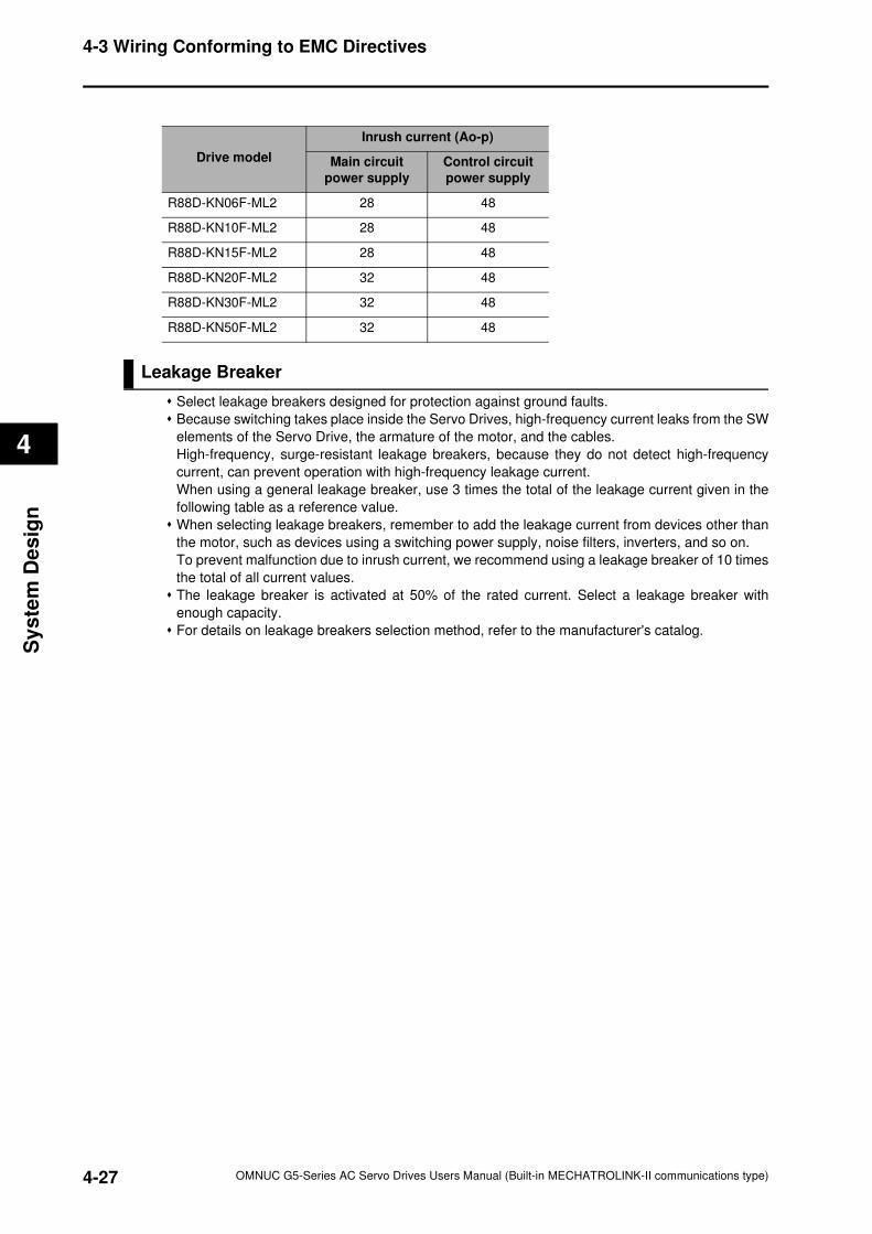
4-3 Wiring Conforming to EMC Directives
4
Sy
ste
m D
es
ign
Leakage Breaker
Select leakage breakers designed for protection against ground faults.
Because switching takes place inside the Servo Drives, high-frequency current leaks from the SW
elements of the Servo Drive, the armature of the motor, and the cables.
High-frequency, surge-resistant leakage breakers, because they do not detect high-frequency
current, can prevent operation with high-frequency leakage current.
When using a general leakage breaker, use 3 times the total of the leakage current given in the
following table as a reference value.
When selecting leakage breakers, remember to add the leakage current from devices other than
the motor, such as devices using a switching power supply, noise filters, inverters, and so on.
To prevent malfunction due to inrush current, we recommend using a leakage breaker of 10 times
the total of all current values.
The leakage breaker is activated at 50% of the rated current. Select a leakage breaker with
enough capacity.
For details on leakage breakers selection method, refer to the manufacturer's catalog.
Drive model
Inrush current (Ao-p)
Main circuit
power supply
Control circuit
power supply
R88D-KN06F-ML2 28 48
R88D-KN10F-ML2 28 48
R88D-KN15F-ML2 28 48
R88D-KN20F-ML2 32 48
R88D-KN30F-ML2 32 48
R88D-KN50F-ML2 32 48
4-27 OMNUC G5-Series AC Servo Drives Users Manual (Built-in MECHATROLINK-II communications type)
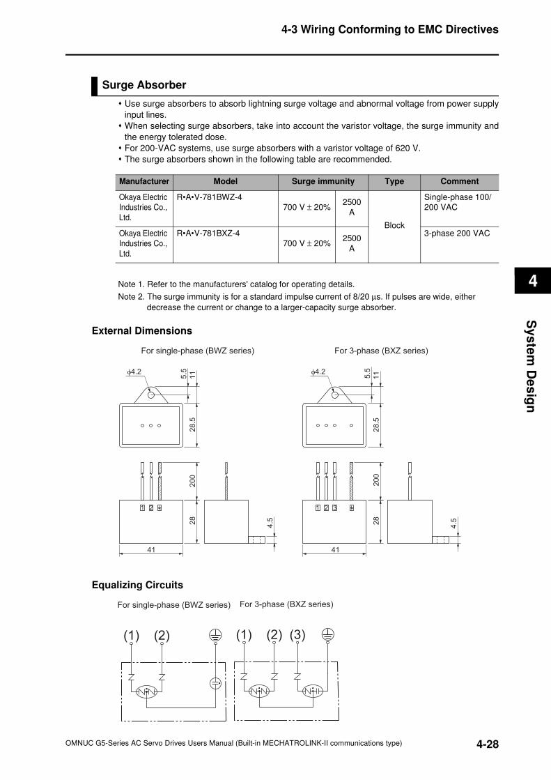
4-3 Wiring Conforming to EMC Directives
4
Sy
ste
m D
es
ign
Surge Absorber
Use surge absorbers to absorb lightning surge voltage and abnormal voltage from power supply
input lines.
When selecting surge absorbers, take into account the varistor voltage, the surge immunity and
the energy tolerated dose.
For 200-VAC systems, use surge absorbers with a varistor voltage of 620 V.
The surge absorbers shown in the following table are recommended.
Note 1. Refer to the manufacturers' catalog for operating details.
Note 2. The surge immunity is for a standard impulse current of 8/20 µs. If pulses are wide, either
decrease the current or change to a larger-capacity surge absorber.
External Dimensions
Equalizing Circuits
Manufacturer Model Surge immunity Type Comment
Okaya Electric
Industries Co.,
Ltd.
R•A•V-781BWZ-4
700 V ± 20%2500
A
Block
Single-phase 100/
200 VAC
Okaya Electric
Industries Co.,
Ltd.
R•A•V-781BXZ-4
700 V ± 20%2500
A
3-phase 200 VAC
1 2 3
28
4.5
28
.51
15.5φ4.2
41
20
0
For 3-phase (BXZ series)For single-phase (BWZ series)
21
28
4.5
28
.51
1
5.5φ4.2
41
20
0
(1) (2) (3)
For 3-phase (BXZ series)For single-phase (BWZ series)
(1) (2)
4-28OMNUC G5-Series AC Servo Drives Users Manual (Built-in MECHATROLINK-II communications type)
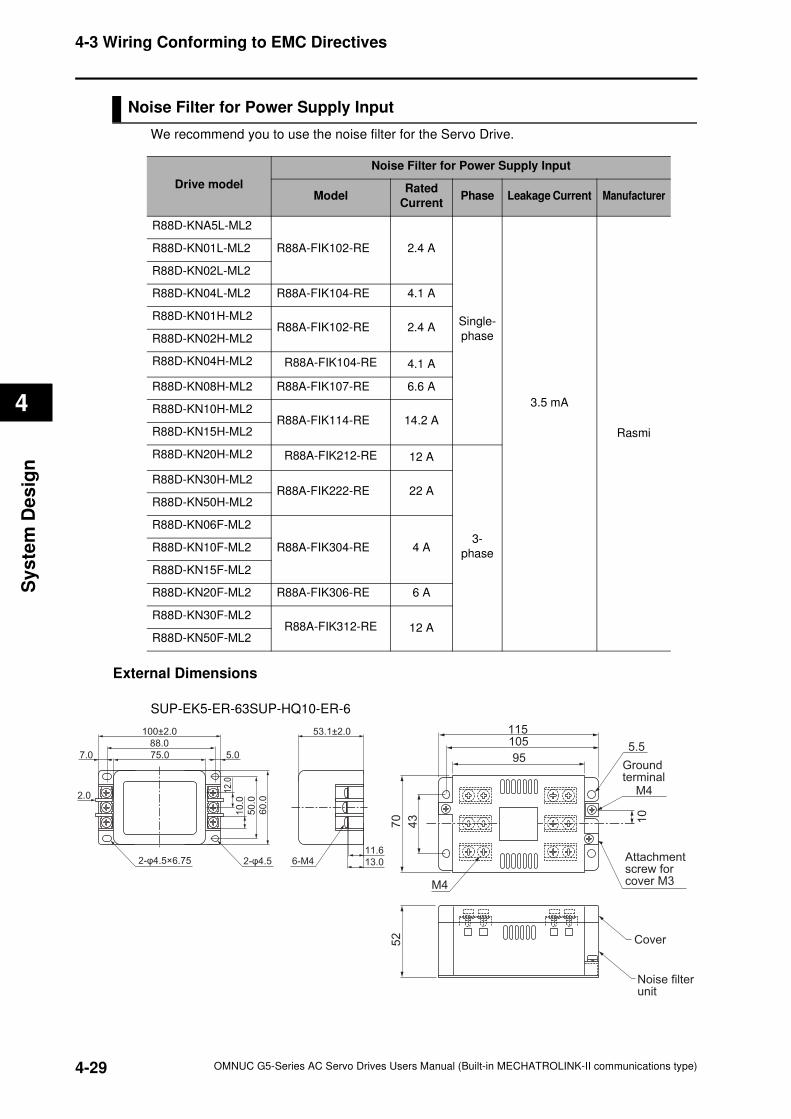
4-3 Wiring Conforming to EMC Directives
4
Sy
ste
m D
es
ign
Noise Filter for Power Supply Input
We recommend you to use the noise filter for the Servo Drive.
External Dimensions
SUP-EK5-ER-63SUP-HQ10-ER-6
Drive model
Noise Filter for Power Supply Input
ModelRated
CurrentPhase Leakage Current Manufacturer
R88D-KNA5L-ML2
R88A-FIK102-RE 2.4 A
Single-
phase
3.5 mA
Rasmi
R88D-KN01L-ML2
R88D-KN02L-ML2
R88D-KN04L-ML2 R88A-FIK104-RE 4.1 A
R88D-KN01H-ML2R88A-FIK102-RE 2.4 A
R88D-KN02H-ML2
R88D-KN04H-ML2 R88A-FIK104-RE 4.1 A
R88D-KN08H-ML2 R88A-FIK107-RE 6.6 A
R88D-KN10H-ML2R88A-FIK114-RE 14.2 A
R88D-KN15H-ML2
R88D-KN20H-ML2 R88A-FIK212-RE 12 A
3-
phase
R88D-KN30H-ML2R88A-FIK222-RE 22 A
R88D-KN50H-ML2
R88D-KN06F-ML2
R88A-FIK304-RE 4 AR88D-KN10F-ML2
R88D-KN15F-ML2
R88D-KN20F-ML2 R88A-FIK306-RE 6 A
R88D-KN30F-ML2R88A-FIK312-RE 12 A
R88D-KN50F-ML2
105115
5.5
43
70
52
10
95Ground terminal
M4
Attachment screw for cover M3
Cover
Noise filter unit
M4
50
.0
60
.0
12
.0
10
.0
11.6
13.0
75.07.0
2.0
88.0
100±2.0 53.1±2.0
5.0
2-φ4.5×6.75 2-φ4.5 6-M4
4-29 OMNUC G5-Series AC Servo Drives Users Manual (Built-in MECHATROLINK-II communications type)
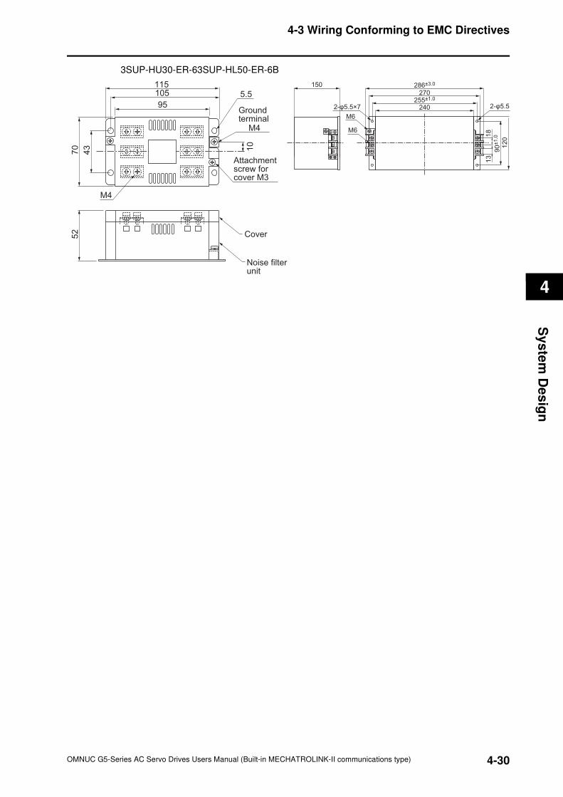
4-3 Wiring Conforming to EMC Directives
4
Sy
ste
m D
es
ign
3SUP-HU30-ER-63SUP-HL50-ER-6B
105115
5.54
3
70
52
10
95Ground terminal
M4
Cover
Noise filter unit
M4
Attachment screw for cover M3
2-φ5.5
12
09
0±1
.018
13
286±3.0
240
150
270255±1.0
2-φ5.5×7
M6
M6
4-30OMNUC G5-Series AC Servo Drives Users Manual (Built-in MECHATROLINK-II communications type)
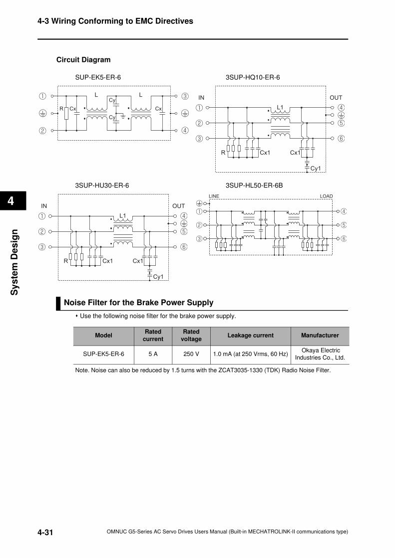
4-3 Wiring Conforming to EMC Directives
4
Sy
ste
m D
es
ign
Circuit Diagram
SUP-EK5-ER-6 3SUP-HQ10-ER-6
3SUP-HU30-ER-6 3SUP-HL50-ER-6B
Noise Filter for the Brake Power Supply
Use the following noise filter for the brake power supply.
Note. Noise can also be reduced by 1.5 turns with the ZCAT3035-1330 (TDK) Radio Noise Filter.
CxR
Cy
Cy
Cx
L L
Cx1Cx1R
L1
Cy1
OUTIN
LOADLINE
Cx1Cx1R
L1
Cy1
OUTIN
ModelRated
current
Rated
voltageLeakage current Manufacturer
SUP-EK5-ER-6 5 A 250 V 1.0 mA (at 250 Vrms, 60 Hz) Okaya Electric
Industries Co., Ltd.
4-31 OMNUC G5-Series AC Servo Drives Users Manual (Built-in MECHATROLINK-II communications type)
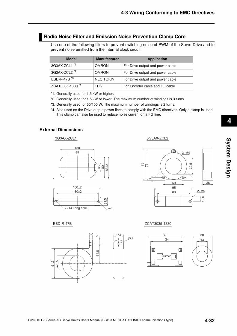
4-3 Wiring Conforming to EMC Directives
4
Sy
ste
m D
es
ign
Radio Noise Filter and Emission Noise Prevention Clamp Core
Use one of the following filters to prevent switching noise of PWM of the Servo Drive and to
prevent noise emitted from the internal clock circuit.
*1. Generally used for 1.5 kW or higher.
*2. Generally used for 1.5 kW or lower. The maximum number of windings is 3 turns.
*3. Generally used for 50/100 W. The maximum number of windings is 2 turns.
*4. Also used on the Drive output power lines to comply with the EMC directives. Only a clamp is used.
This clamp can also be used to reduce noise current on a FG line.
External Dimensions
Model Manufacturer Application
3G3AX-ZCL1 *1 OMRON For Drive output and power cable
3G3AX-ZCL2 *2 OMRON For Drive output and power cable
ESD-R-47B *3 NEC TOKIN For Drive output and power cable
ZCAT3035-1330 *4 TDK For Encoder cable and I/O cable
2−M5
3−M4
95
26
78
80
12
.5
72
50
7
39
.5
3G3AX-ZCL23G3AX-ZCL1
51
.5
φ2
5.5
17.5
φ5.1
3.0
6.5
34
.0
ESD-R-47B
34 13
3039
ZCAT3035-1330
83
±2
35
31
.58
0
130
85
180±2
160±2
7×14 Long hole φ7
4-32OMNUC G5-Series AC Servo Drives Users Manual (Built-in MECHATROLINK-II communications type)
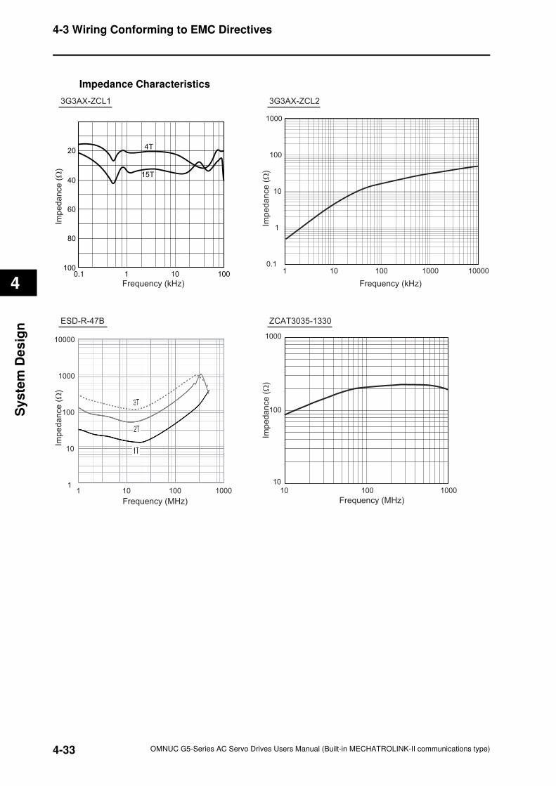
4-3 Wiring Conforming to EMC Directives
4
Sy
ste
m D
es
ign
Impedance Characteristics
10 100 10000
1000
100
10
1
0.1
Frequency (kHz)Frequency (kHz)
Impe
da
nce
(Ω
)
Impe
da
nce
(Ω
)
1 1000
3G3AX-ZCL23G3AX-ZCL1
10000
1000
100
10
1
Impe
da
nce
(Ω
)
10 100
Frequency (MHz)
1 1000
ESD-R-47B ZCAT3035-1330
10 100
Frequency (MHz)
1000
1000
100
10
Impe
da
nce
(Ω
)
20
40
60
80
1001 10 1000.1
4T
15T
4-33 OMNUC G5-Series AC Servo Drives Users Manual (Built-in MECHATROLINK-II communications type)
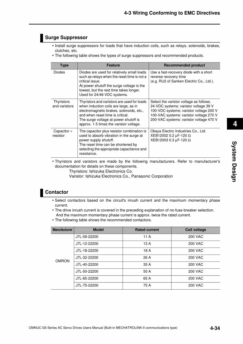
4-3 Wiring Conforming to EMC Directives
4
Sy
ste
m D
es
ign
Surge Suppressor
Install surge suppressors for loads that have induction coils, such as relays, solenoids, brakes,
clutches, etc.
The following table shows the types of surge suppressors and recommended products.
Thyristors and varistors are made by the following manufacturers. Refer to manufacturer's
documentation for details on these components.
Thyristors: Ishizuka Electronics Co.
Varistor: Ishizuka Electronics Co., Panasonic Corporation
Contactor
Select contactors based on the circuit's inrush current and the maximum momentary phase
current.
The drive inrush current is covered in the preceding explanation of no-fuse breaker selection.
And the maximum momentary phase current is approx. twice the rated current.
The following table shows the recommended contactors.
Type Feature Recommended product
Diodes Diodes are used for relatively small loads
such as relays when the reset time is not a
critical issue.
At power shutoff the surge voltage is the
lowest, but the rest time takes longer.
Used for 24/48-VDC systems.
Use a fast-recovery diode with a short
reverse recovery time
(e.g. RU2 of Sanken Electric Co., Ltd.).
Thyristors
and varistors
Thyristors and varistors are used for loads
when induction coils are large, as in
electromagnetic brakes, solenoids, etc.,
and when reset time is critical.
The surge voltage at power shutoff is
approx. 1.5 times the varistor voltage.
Select the varistor voltage as follows.
24-VDC systems: varistor voltage 39 V
100-VDC systems: varistor voltage 200 V
100-VAC systems: varistor voltage 270 V
200-VAC systems: varistor voltage 470 V
Capacitor +
resistor
The capacitor plus resistor combination is
used to absorb vibration in the surge at
power supply shutoff.
The reset time can be shortened by
selecting the appropriate capacitance and
resistance.
Okaya Electric Industries Co., Ltd.
XEB12002 0.2 µF-120 Ω
XEB12003 0.3 µF-120 Ω
Manufacturer Model Rated current Coil voltage
OMRON
J7L-09-22200 11 A 200 VAC
J7L-12-22200 13 A 200 VAC
J7L-18-22200 18 A 200 VAC
J7L-32-22200 26 A 200 VAC
J7L-40-22200 35 A 200 VAC
J7L-50-22200 50 A 200 VAC
J7L-65-22200 65 A 200 VAC
J7L-75-22200 75 A 200 VAC
4-34OMNUC G5-Series AC Servo Drives Users Manual (Built-in MECHATROLINK-II communications type)
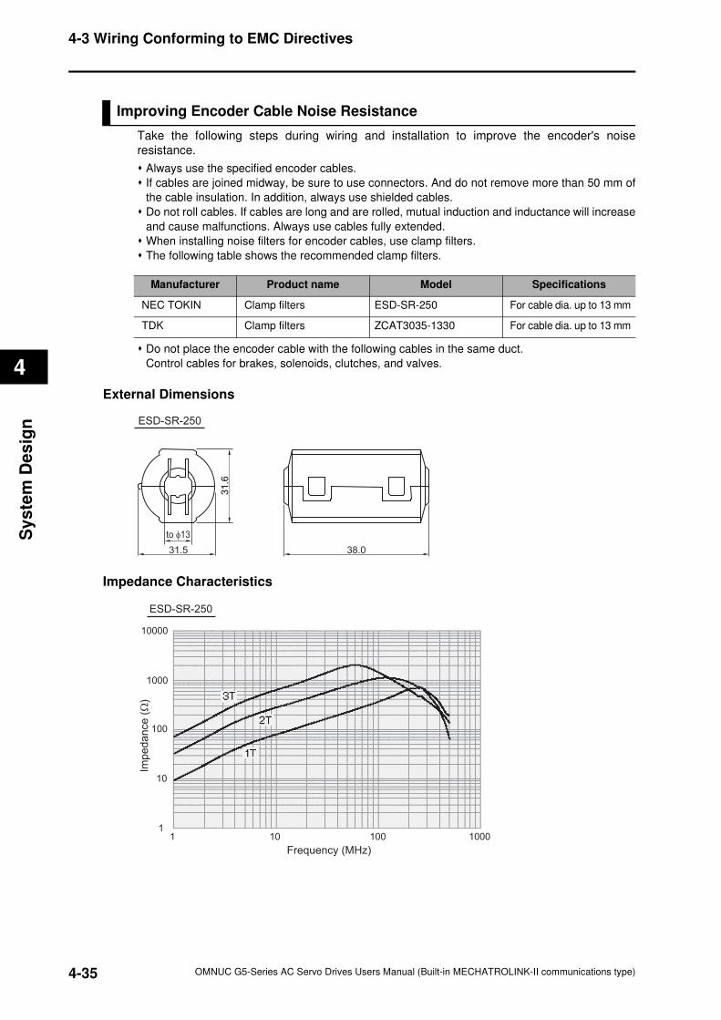
4-3 Wiring Conforming to EMC Directives
4
Sy
ste
m D
es
ign
Improving Encoder Cable Noise Resistance
Take the following steps during wiring and installation to improve the encoder's noise
resistance.
Always use the specified encoder cables.
If cables are joined midway, be sure to use connectors. And do not remove more than 50 mm of
the cable insulation. In addition, always use shielded cables.
Do not roll cables. If cables are long and are rolled, mutual induction and inductance will increase
and cause malfunctions. Always use cables fully extended.
When installing noise filters for encoder cables, use clamp filters.
The following table shows the recommended clamp filters.
Do not place the encoder cable with the following cables in the same duct.
Control cables for brakes, solenoids, clutches, and valves.
External Dimensions
Impedance Characteristics
Manufacturer Product name Model Specifications
NEC TOKIN Clamp filters ESD-SR-250 For cable dia. up to 13 mm
TDK Clamp filters ZCAT3035-1330 For cable dia. up to 13 mm
31.5
to φ13
31
.6
38.0
ESD-SR-250
10000
1000
100
10
1
Impe
da
nce
(Ω
)
10 100
Frequency (MHz)
1 1000
ESD-SR-250
4-35 OMNUC G5-Series AC Servo Drives Users Manual (Built-in MECHATROLINK-II communications type)
4-3 Wiring Conforming to EMC Directives
4
Sy
ste
m D
es
ign
Improving Control I/O Signal Noise Resistance
Positioning can be affected and I/O signal errors can occur if control I/O is influenced by noise.
Use completely separate power supplies for the control power supply (especially 24 VDC) and the
external operation power supply. In particular, do not connect the 2 power supply ground wires.
Install a noise filter on the primary side of the control power supply.
If motors with brakes are being used, do not use the same 24-VDC power supply for both the
brakes and the control I/O. Additionally, do not connect the ground wires. Connecting the ground
wires may cause I/O signal errors.
Keep the power supply for pulse commands and error counter reset input lines separated from the
control power supply as far as possible. In particular, do not connect the 2 power supply ground
wires.
We recommend using line drivers for the pulse command and error counter reset outputs.
Always use twisted-pair shielded cable for the pulse command and error counter reset signal lines,
and connect both ends of the shield cable to frame grounds.
If the control power supply wiring is long, noise resistance can be improved by adding 1-µF
laminated ceramic capacitors between the control power supply and ground at the drive input
section or the controller output section.
For open collector inputs/outputs, keep the length of wires to within 2 m.
4-36OMNUC G5-Series AC Servo Drives Users Manual (Built-in MECHATROLINK-II communications type)
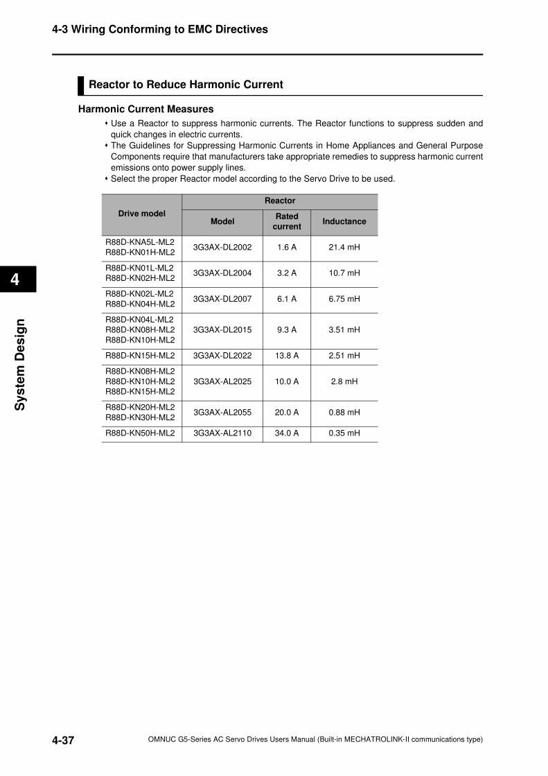
4-3 Wiring Conforming to EMC Directives
4
Sy
ste
m D
es
ign
Reactor to Reduce Harmonic Current
Harmonic Current Measures
Use a Reactor to suppress harmonic currents. The Reactor functions to suppress sudden and
quick changes in electric currents.
The Guidelines for Suppressing Harmonic Currents in Home Appliances and General Purpose
Components require that manufacturers take appropriate remedies to suppress harmonic current
emissions onto power supply lines.
Select the proper Reactor model according to the Servo Drive to be used.
Drive model
Reactor
ModelRated
currentInductance
R88D-KNA5L-ML2
R88D-KN01H-ML23G3AX-DL2002 1.6 A 21.4 mH
R88D-KN01L-ML2
R88D-KN02H-ML23G3AX-DL2004 3.2 A 10.7 mH
R88D-KN02L-ML2
R88D-KN04H-ML23G3AX-DL2007 6.1 A 6.75 mH
R88D-KN04L-ML2
R88D-KN08H-ML2
R88D-KN10H-ML2
3G3AX-DL2015 9.3 A 3.51 mH
R88D-KN15H-ML2 3G3AX-DL2022 13.8 A 2.51 mH
R88D-KN08H-ML2
R88D-KN10H-ML2
R88D-KN15H-ML2
3G3AX-AL2025 10.0 A 2.8 mH
R88D-KN20H-ML2
R88D-KN30H-ML23G3AX-AL2055 20.0 A 0.88 mH
R88D-KN50H-ML2 3G3AX-AL2110 34.0 A 0.35 mH
4-37 OMNUC G5-Series AC Servo Drives Users Manual (Built-in MECHATROLINK-II communications type)
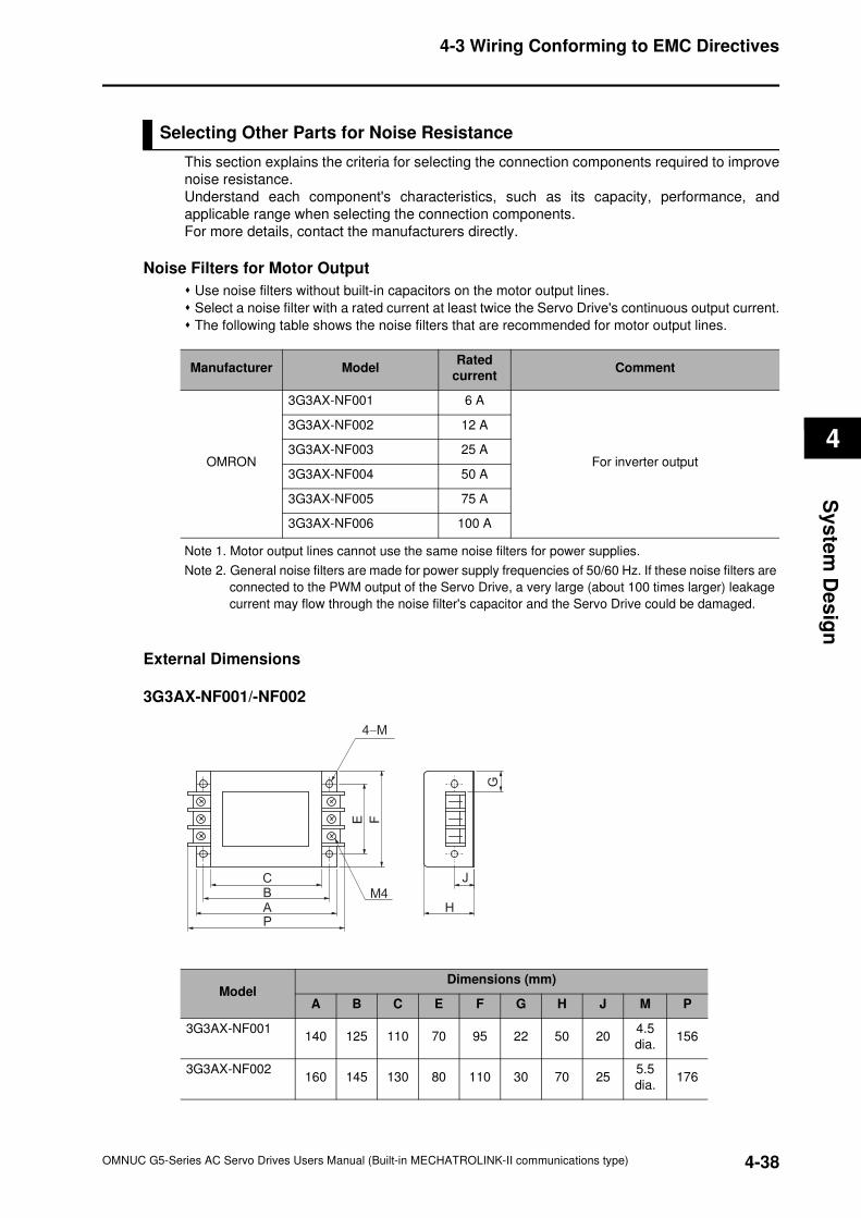
4-3 Wiring Conforming to EMC Directives
4
Sy
ste
m D
es
ign
Selecting Other Parts for Noise Resistance
This section explains the criteria for selecting the connection components required to improve
noise resistance.
Understand each component's characteristics, such as its capacity, performance, and
applicable range when selecting the connection components.
For more details, contact the manufacturers directly.
Noise Filters for Motor Output
Use noise filters without built-in capacitors on the motor output lines.
Select a noise filter with a rated current at least twice the Servo Drive's continuous output current.
The following table shows the noise filters that are recommended for motor output lines.
Note 1. Motor output lines cannot use the same noise filters for power supplies.
Note 2. General noise filters are made for power supply frequencies of 50/60 Hz. If these noise filters are
connected to the PWM output of the Servo Drive, a very large (about 100 times larger) leakage
current may flow through the noise filter's capacitor and the Servo Drive could be damaged.
External Dimensions
3G3AX-NF001/-NF002
Manufacturer ModelRated
currentComment
OMRON
3G3AX-NF001 6 A
For inverter output
3G3AX-NF002 12 A
3G3AX-NF003 25 A
3G3AX-NF004 50 A
3G3AX-NF005 75 A
3G3AX-NF006 100 A
4−M
M4
CBAP
E F
J
H
G
ModelDimensions (mm)
A B C E F G H J M P
3G3AX-NF001140 125 110 70 95 22 50 20
4.5
dia.156
3G3AX-NF002160 145 130 80 110 30 70 25
5.5
dia.176
4-38OMNUC G5-Series AC Servo Drives Users Manual (Built-in MECHATROLINK-II communications type)
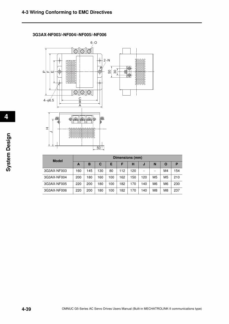
4-3 Wiring Conforming to EMC Directives
4
Sy
ste
m D
es
ign
3G3AX-NF003/-NF004/-NF005/-NF006
CBA
P F E
6−O
2−N
50
30
4−φ6.5
50
HJ
ModelDimensions (mm)
A B C E F H J N O P
3G3AX-NF003 160 145 130 80 112 120 − − M4 154
3G3AX-NF004 200 180 160 100 162 150 120 M5 M5 210
3G3AX-NF005 220 200 180 100 182 170 140 M6 M6 230
3G3AX-NF006 220 200 180 100 182 170 140 M8 M8 237
4-39 OMNUC G5-Series AC Servo Drives Users Manual (Built-in MECHATROLINK-II communications type)
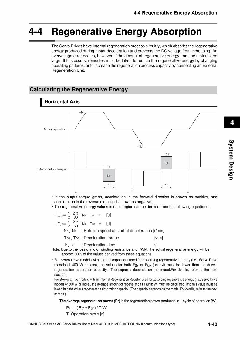
4-4 Regenerative Energy Absorption
4
Sy
ste
m D
es
ign
4-4 Regenerative Energy Absorption
The Servo Drives have internal regeneration process circuitry, which absorbs the regenerative
energy produced during motor deceleration and prevents the DC voltage from increasing. An
overvoltage error occurs, however, if the amount of regenerative energy from the motor is too
large. If this occurs, remedies must be taken to reduce the regenerative energy by changing
operating patterns, or to increase the regeneration process capacity by connecting an External
Regeneration Unit.
Calculating the Regenerative Energy
Horizontal Axis
In the output torque graph, acceleration in the forward direction is shown as positive, and
acceleration in the reverse direction is shown as negative.
The regenerative energy values in each region can be derived from the following equations.
Note. Due to the loss of motor winding resistance and PWM, the actual regenerative energy will be
approx. 90% of the values derived from these equations.
For Servo Drive models with internal capacitors used for absorbing regenerative energy (i.e., Servo Drive
models of 400 W or less), the values for both Eg1 or Eg2 (unit: J) must be lower than the drive's
regeneration absorption capacity. (The capacity depends on the model.For details, refer to the next
section.)
For Servo Drive models with an Internal Regeneration Resistor used for absorbing regenerative energy (i.e., Servo Drive
models of 500 W or more), the average amount of regeneration Pr (unit: W) must be calculated, and this value must be
lower than the drive's regeneration absorption capacity. (The capacity depends on the model.For details, refer to the next
section.)
The average regeneration power (Pr) is the regeneration power produced in 1 cycle of operation [W].
Motor operation
Motor output torque
+N1
−N2
TD1
TD2
t 1 t 2
T
Eg1Eg1
Eg2Eg2
N1 , N2 : Rotation speed at start of deceleration [r/min]
: Deceleration torque [N·m]
: Deceleration time [s]
TD1 , TD2
t1, t2
2Eg1Eg=Pr ( + ) / T[W]
T: Operation cycle [s]
4-40OMNUC G5-Series AC Servo Drives Users Manual (Built-in MECHATROLINK-II communications type)
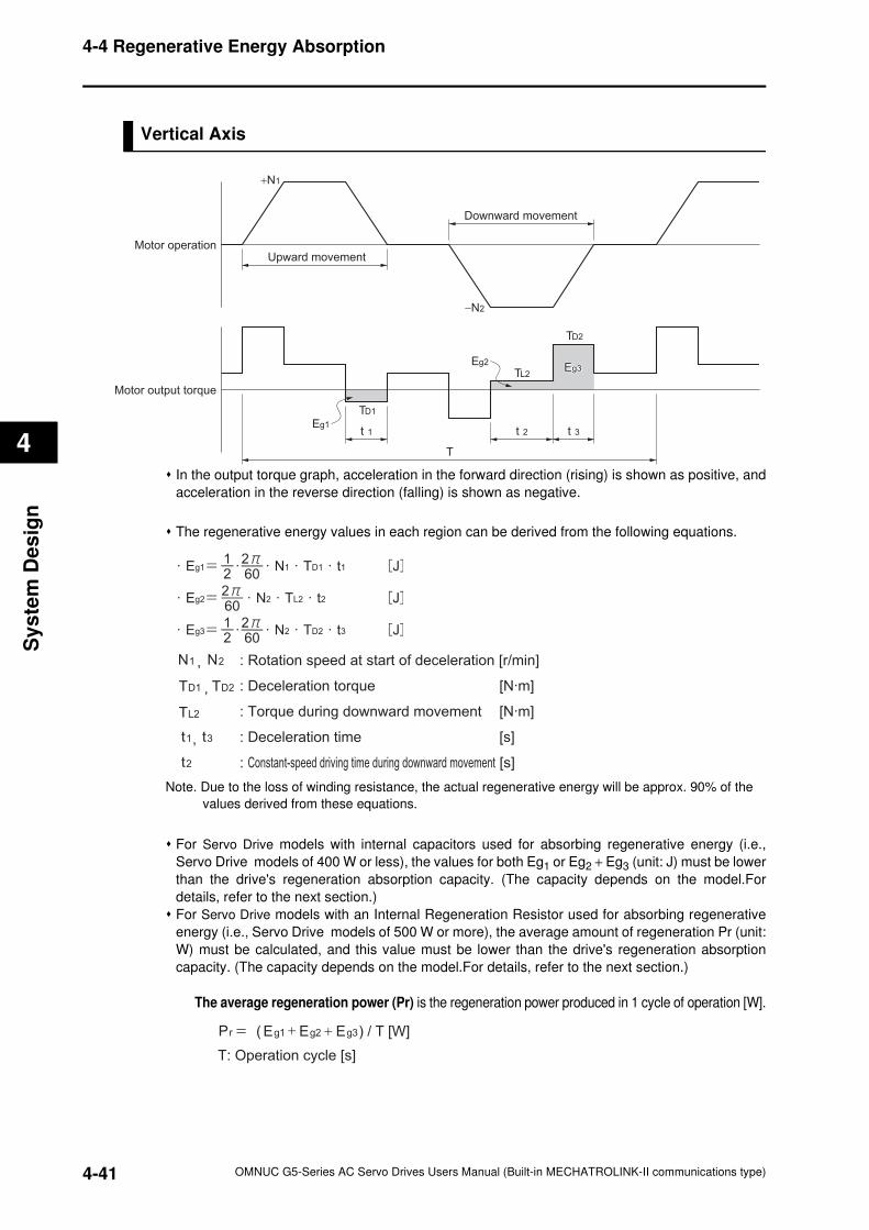
4-4 Regenerative Energy Absorption
4
Sy
ste
m D
es
ign
Vertical Axis
In the output torque graph, acceleration in the forward direction (rising) is shown as positive, and
acceleration in the reverse direction (falling) is shown as negative.
The regenerative energy values in each region can be derived from the following equations.
Note. Due to the loss of winding resistance, the actual regenerative energy will be approx. 90% of the
values derived from these equations.
For Servo Drive models with internal capacitors used for absorbing regenerative energy (i.e.,
Servo Drive models of 400 W or less), the values for both Eg1 or Eg2 + Eg3 (unit: J) must be lower
than the drive's regeneration absorption capacity. (The capacity depends on the model.For
details, refer to the next section.)
For Servo Drive models with an Internal Regeneration Resistor used for absorbing regenerative
energy (i.e., Servo Drive models of 500 W or more), the average amount of regeneration Pr (unit:
W) must be calculated, and this value must be lower than the drive's regeneration absorption
capacity. (The capacity depends on the model.For details, refer to the next section.)
The average regeneration power (Pr) is the regeneration power produced in 1 cycle of operation [W].
Motor operation
Motor output torque
+N1
−N2
t 1 t 2 t 3
T
Eg1
Eg3Eg3
Upward movement
Downward movement
TD2
TL2
TD1
Eg2
N1 , N2 : Rotation speed at start of deceleration [r/min]
: Deceleration torque [N·m]
: Torque during downward movement [N·m]
: Deceleration time [s]
: Constant-speed driving time during downward movement [s]
TD1 , TD2
t1, t3
TL2
t2
2Eg1Eg=Pr ( + ) / T [W]
T: Operation cycle [s]
3Eg+
4-41 OMNUC G5-Series AC Servo Drives Users Manual (Built-in MECHATROLINK-II communications type)
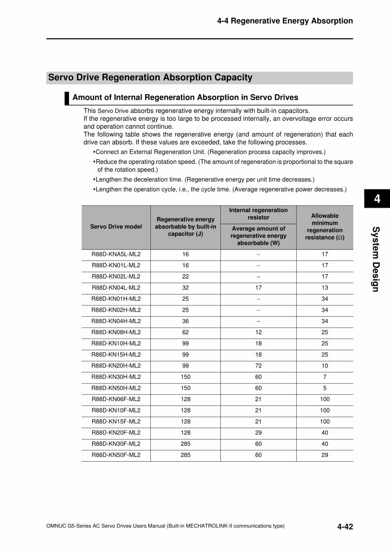
4-4 Regenerative Energy Absorption
4
Sy
ste
m D
es
ign
Servo Drive Regeneration Absorption Capacity
Amount of Internal Regeneration Absorption in Servo Drives
This Servo Drive absorbs regenerative energy internally with built-in capacitors.
If the regenerative energy is too large to be processed internally, an overvoltage error occurs
and operation cannot continue.
The following table shows the regenerative energy (and amount of regeneration) that each
drive can absorb. If these values are exceeded, take the following processes.
Connect an External Regeneration Unit. (Regeneration process capacity improves.)
Reduce the operating rotation speed. (The amount of regeneration is proportional to the square
of the rotation speed.)
Lengthen the deceleration time. (Regenerative energy per unit time decreases.)
Lengthen the operation cycle, i.e., the cycle time. (Average regenerative power decreases.)
Servo Drive model
Regenerative energy
absorbable by built-in
capacitor (J)
Internal regeneration
resistor Allowable
minimum
regeneration
resistance (Ω)
Average amount of
regenerative energy
absorbable (W)
R88D-KNA5L-ML2 16 − 17
R88D-KN01L-ML2 16 − 17
R88D-KN02L-ML2 22 − 17
R88D-KN04L-ML2 32 17 13
R88D-KN01H-ML2 25 − 34
R88D-KN02H-ML2 25 − 34
R88D-KN04H-ML2 36 − 34
R88D-KN08H-ML2 62 12 25
R88D-KN10H-ML2 99 18 25
R88D-KN15H-ML2 99 18 25
R88D-KN20H-ML2 99 72 10
R88D-KN30H-ML2 150 60 7
R88D-KN50H-ML2 150 60 5
R88D-KN06F-ML2 128 21 100
R88D-KN10F-ML2 128 21 100
R88D-KN15F-ML2 128 21 100
R88D-KN20F-ML2 128 29 40
R88D-KN30F-ML2 285 60 40
R88D-KN50F-ML2 285 60 29
4-42OMNUC G5-Series AC Servo Drives Users Manual (Built-in MECHATROLINK-II communications type)
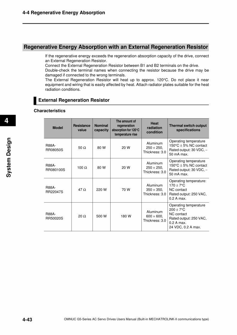
4-4 Regenerative Energy Absorption
4
Sy
ste
m D
es
ign
Regenerative Energy Absorption with an External Regeneration Resistor
If the regenerative energy exceeds the regeneration absorption capacity of the drive, connect
an External Regeneration Resistor.
Connect the External Regeneration Resistor between B1 and B2 terminals on the drive.
Double-check the terminal names when connecting the resistor because the drive may be
damaged if connected to the wrong terminals.
The External Regeneration Resistor will heat up to approx. 120°C. Do not place it near
equipment and wiring that is easily affected by heat. Attach radiator plates suitable for the heat
radiation conditions.
External Regeneration Resistor
Characteristics
ModelResistance
value
Nominal
capacity
The amount of
regeneration
absorption for 120°C
temperature rise
Heat
radiation
condition
Thermal switch output
specifications
R88A-
RR08050S50 Ω 80 W 20 W
Aluminum
250 × 250,
Thickness: 3.0
Operating temperature
150°C ± 5% NC contact
Rated output: 30 VDC, −
50 mA max.
R88A-
RR080100S100 Ω 80 W 20 W
Aluminum
250 × 250,
Thickness: 3.0
Operating temperature
150°C ± 5% NC contact
Rated output: 30 VDC, −
50 mA max.
R88A-
RR22047S47 Ω 220 W 70 W
Aluminum
350 × 350,
Thickness: 3.0
Operating temperature:
170 ± 7°C
NC contact
Rated output: 250 VAC,
0.2 A max.
R88A-
RR50020S20 Ω 500 W 180 W
Aluminum
600 × 600,
Thickness: 3.0
Operating temperature
200 ± 7°C
NC contact
Rated output: 250 VAC,
0.2 A max.
24 VDC, 0.2 A max.
4-43 OMNUC G5-Series AC Servo Drives Users Manual (Built-in MECHATROLINK-II communications type)
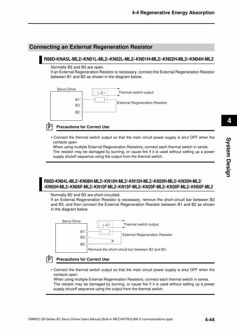
4-4 Regenerative Energy Absorption
4
Sy
ste
m D
es
ign
Connecting an External Regeneration Resistor
R88D-KNA5L-ML2/-KN01L-ML2/-KN02L-ML2/-KN01H-ML2/-KN02H-ML2/-KN04H-ML2
Normally B2 and B3 are open.
If an External Regeneration Resistor is necessary, connect the External Regeneration Resistor
between B1 and B2 as shown in the diagram below.
Precautions for Correct Use
Connect the thermal switch output so that the main circuit power supply is shut OFF when the
contacts open.
When using multiple External Regeneration Resistors, connect each thermal switch in series.
The resistor may be damaged by burning, or cause fire if it is used without setting up a power
supply shutoff sequence using the output from the thermal switch.
R88D-KN04L-ML2/-KN08H-ML2/-KN10H-ML2/-KN15H-ML2/-KN20H-ML2/-KN30H-ML2/-KN50H-ML2/-KN06F-ML2/-KN10F-ML2/-KN15F-ML2/-KN20F-ML2/-KN30F-ML2/-KN50F-ML2
Normally B2 and B3 are short-circuited.
If an External Regeneration Resistor is necessary, remove the short-circuit bar between B2
and B3, and then connect the External Regeneration Resistor between B1 and B2 as shown
in the diagram below.
Precautions for Correct Use
Connect the thermal switch output so that the main circuit power supply is shut OFF when the
contacts open.
When using multiple External Regeneration Resistors, connect each thermal switch in series.
The resistor may be damaged by burning, or cause fire if it is used without setting up a power
supply shutoff sequence using the output from the thermal switch.
Servo Drive
B1
B3External Regeneration Resistor
θ > Thermal switch output
B2
Servo Drive
B1
B3External Regeneration Resistor
Remove the short-circuit bar between B2 and B3.
θ > Thermal switch output
B2
4-44OMNUC G5-Series AC Servo Drives Users Manual (Built-in MECHATROLINK-II communications type)
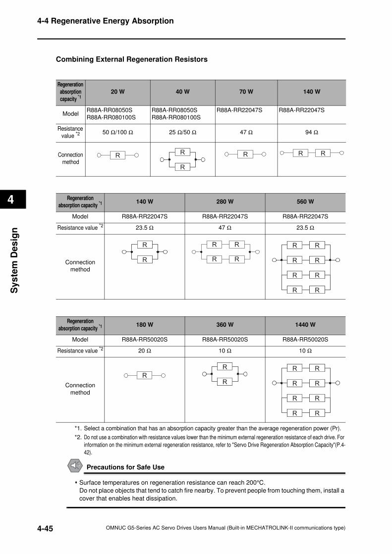
4-4 Regenerative Energy Absorption
4
Sy
ste
m D
es
ign
Combining External Regeneration Resistors
*1. Select a combination that has an absorption capacity greater than the average regeneration power (Pr).
*2. Do not use a combination with resistance values lower than the minimum external regeneration resistance of each drive. For
information on the minimum external regeneration resistance, refer to "Servo Drive Regeneration Absorption Capacity"(P.4-
42).
Precautions for Safe Use
Surface temperatures on regeneration resistance can reach 200°C.
Do not place objects that tend to catch fire nearby. To prevent people from touching them, install a
cover that enables heat dissipation.
Regeneration
absorption
capacity *120 W 40 W 70 W 140 W
ModelR88A-RR08050S
R88A-RR080100S
R88A-RR08050S
R88A-RR080100S
R88A-RR22047S R88A-RR22047S
Resistance
value *250 Ω/100 Ω 25 Ω/50 Ω 47 Ω 94 Ω
Connection
methodR
R
R
R
R R R R
Regeneration
absorption capacity *1140 W 280 W 560 W
Model R88A-RR22047S R88A-RR22047S R88A-RR22047S
Resistance value *2 23.5 Ω 47 Ω 23.5 Ω
Connection
method
R
R
R
R
R R
R R
R R
R R
R R
R R
R R
R R
R R
R R
Regeneration
absorption capacity *1180 W 360 W 1440 W
Model R88A-RR50020S R88A-RR50020S R88A-RR50020S
Resistance value *2 20 Ω 10 Ω 10 Ω
Connection
method
RR
R
R
R
R R
R R
R R
R R
R R
R R
R R
R R
4-45 OMNUC G5-Series AC Servo Drives Users Manual (Built-in MECHATROLINK-II communications type)
OMNUC G5-Series AC Servo Drives Users Manual (Built-in MECHATROLINK-II communications type)
5
5
This chapter explains an outline of operations available in various CONTROL
modes and explains the contents of setting.
5-1 Position Control............................................................5-1
5-2 Speed Control ...............................................................5-4
5-3 Torque Control..............................................................5-6
5-4 Full Closing Control .....................................................5-9
BASIC CONTROL Mode
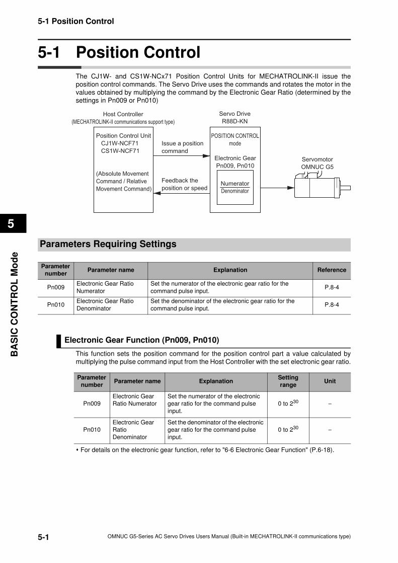
5-1
5-1 Position Control
OMNUC G5-Series AC Servo Drives Users Manual (Built-in MECHATROLINK-II communications type)
5
BA
SIC
CO
NT
RO
L M
od
e
5-1 Position Control
The CJ1W- and CS1W-NCx71 Position Control Units for MECHATROLINK-II issue the
position control commands. The Servo Drive uses the commands and rotates the motor in the
values obtained by multiplying the command by the Electronic Gear Ratio (determined by the
settings in Pn009 or Pn010)
Parameters Requiring Settings
Electronic Gear Function (Pn009, Pn010)
This function sets the position command for the position control part a value calculated by
multiplying the pulse command input from the Host Controller with the set electronic gear ratio.
For details on the electronic gear function, refer to "6-6 Electronic Gear Function" (P.6-18).
Servo Drive
R88D-KN
Servomotor
OMNUC G5
Host Controller
(MECHATROLINK-II communications support type)
Electronic Gear
Pn009, Pn010
POSITION CONTROL
mode
Position Control Unit
CJ1W-NCF71
CS1W-NCF71
(Absolute Movement
Command / Relative
Movement Command)
Issue a position
command
Feedback the
position or speedNumerator
Denominator
Parameter
numberParameter name Explanation Reference
Pn009Electronic Gear Ratio
Numerator
Set the numerator of the electronic gear ratio for the
command pulse input.P.8-4
Pn010Electronic Gear Ratio
Denominator
Set the denominator of the electronic gear ratio for the
command pulse input.P.8-4
Parameter
numberParameter name Explanation
Setting
rangeUnit
Pn009
Electronic Gear
Ratio Numerator
Set the numerator of the electronic
gear ratio for the command pulse
input.
0 to 230−
Pn010
Electronic Gear
Ratio
Denominator
Set the denominator of the electronic
gear ratio for the command pulse
input.
0 to 230−
5-2
5-1 Position Control
OMNUC G5-Series AC Servo Drives Users Manual (Built-in MECHATROLINK-II communications type)
5
BA
SIC
CO
NT
RO
L M
od
e
Related Functions
Parameter
numberParameter name Explanation Reference
Pn222Position Command Filter
Time Constant
Set the time constant of the first-order lag filter for the
position command.P.8-24
Pn431Positioning Completion
Range 1
Set the threshold of position error for output of the positioning
completion signal.P.8-36
Pn432Positioning Completion
Condition Selection
Select the condition under which the positioning completion
signal is output.P.8-36
Pn433Positioning Completion
Hold Time
Set the INP signal output time.P.8-37
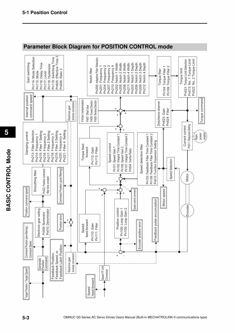
5-3
5-1 Position Control
OMNUC G5-Series AC Servo Drives Users Manual (Built-in MECHATROLINK-II communications type)
5
BA
SIC
CO
NT
RO
L M
od
e
Parameter Block Diagram for POSITION CONTROL mode
Pn
103
: F
eedback
Filt
er
Tim
e C
onst
ant 1
Pn
108
: F
eedback
Filt
er
Tim
e C
onst
ant 2
Pn
610
: F
unct
ion E
xpansi
on
Settin
g
Sp
ee
d d
ete
ctio
n f
ilte
r
Pn
52
1: T
orqu
e Li
mit
Sel
ectio
n
Pn
01
3:
No
. 1
To
rqu
e L
imit
Pn
52
2:
No
. 2
To
rqu
e L
imit
En
co
de
rM
oto
r
Mai
n
pow
er
supp
ly
++
+
+
+
+
+ +−
+
−
Pn22
2: P
ositi
on c
omm
and
filte
r tim
e co
nsta
nt
Pn
00
9:
Nu
me
rato
r
Pn
01
0:
De
no
min
ato
r
Pn
10
0:
Lo
op
Ga
in 1
Pn
10
5:
Lo
op
Ga
in 2
Ele
ctro
nic
ge
ar
sett
ing
Pn
21
3:
Filt
er
Se
lectio
n
Pn
21
4:
Fre
qu
en
cy 1
Pn
21
5:
Filt
er
1 S
ett
ing
Pn
21
6:
Fre
qu
en
cy 2
Pn
21
7:
Filt
er
2 S
ett
ing
Pn
21
8:
Fre
qu
en
cy 3
Pn
21
9:
Filt
er
3 S
ett
ing
Pn
22
0:
Fre
qu
en
cy 4
Pn
22
1:
Filt
er
4 S
ett
ing
Da
mp
ing
co
ntr
ol
Po
sitio
n c
on
tro
l
Pn
11
0:
Ga
in
Pn
11
1:
Filt
er
Sp
ee
d
fee
d-f
orw
ard
Pn
11
2:
Ga
in
Pn
11
3:
Filt
er
To
rqu
e f
ee
d
forw
ard
Pn
62
3:
Ga
in
Pn
62
4:
Filt
er
Dis
turb
ance
obs
erve
r
Pn60
7: O
ffset
Valu
e
Pn60
8: F
orwa
rd D
irecti
on
Pn60
9: R
ever
se D
irecti
on
Fric
tion
com
pens
atio
n
Pn
11
4: M
od
e S
ele
ctio
n
Pn
11
5:
Mo
de
Pn
11
6:
De
lay T
ime
Pn
11
7:
Le
ve
l
Pn
11
8:
Hyste
resis
Pn
11
9:
Sw
itch
ing
Tim
e
Pn
60
5:
Eff
ective
Tim
e 3
Pn
60
6: R
atio
3
Ga
in s
witch
ing
Sm
oo
thin
g f
ilte
r Pn1
01: S
peed
Gai
n 1
Pn1
02: I
nteg
ral T
ime
Con
stan
t 1
Pn1
06: S
peed
Gai
n 2
Pn1
07: I
nteg
ral T
ime
Con
stan
t 2
Pn0
04: I
nert
ia R
atio
Sp
ee
d c
on
tro
l
To
rqu
e lim
it
Pn61
1: R
espo
nse
Setti
ng
Cu
rre
nt
co
ntr
ol
Ele
ctro
nic
gear
reve
rse
conv
ersi
on
Pn
104
: T
orq
ue F
ilte
r 1
Pn
109
: T
orq
ue F
ilte
r 2
To
rqu
e f
ilte
r
Sp
ee
d d
ete
ctio
n
Com
man
d Po
sitio
n (p
re-fi
lterin
g) /
Com
man
d Sp
eed
En
cod
er
po
sitio
n e
rro
r
Spee
d co
ntro
l com
man
d
Mo
tor
sp
ee
d
To
rqu
e c
om
ma
nd
Inte
rna
l p
ositio
n
co
mm
an
d s
pe
ed
Fe
ed
ba
ck p
uls
e a
ccu
mu
latio
n
Pos
ition
com
man
d sp
eed
Pn
20
0: A
dapt
ive
Filte
r Sel
ectio
n
Pn
20
1:
Fre
qu
en
cy 1
Pn
20
4:
Fre
qu
en
cy 2
Pn
20
7:
Fre
qu
en
cy 3
Pn
21
0:
Fre
qu
en
cy 4
Pn
20
2:
No
tch
1 W
idth
Pn
20
5:
No
tch
2 W
idth
Pn
20
8:
No
tch
3 W
idth
Pn
21
1:
No
tch
4 W
idth
Pn
20
3:
No
tch
1 D
ep
th
Pn
20
6:
No
tch
2 D
ep
th
Pn
20
9:
No
tch
3 D
ep
th
Pn
21
2:
No
tch
4 D
ep
th
No
tch
filt
er
Elec
troni
c ge
ar
reve
rse
conv
ersi
on
++
Ge
ne
rate
P
osi
tion
C
om
ma
nd
Targ
et P
ositi
on /
Targ
et S
peed
Com
man
d P
ositi
on (p
ost f
ilter
ing)
Pos
ition
err
or
Fe
ed
ba
ck P
ositio
n,
Fe
ed
ba
ck S
pe
ed
, o
r
Fe
ed
ba
ck L
atc
h P
ositio
n
+−
Spee
d FF
Uni
t
Con
vers
ion
Sp
ee
d
fee
d-f
orw
ard
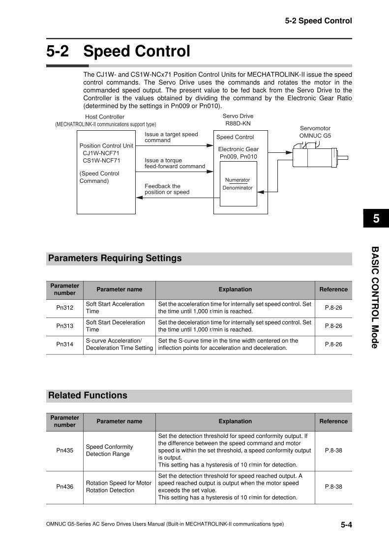
5-4
5-2 Speed Control
OMNUC G5-Series AC Servo Drives Users Manual (Built-in MECHATROLINK-II communications type)
5
BA
SIC
CO
NT
RO
L M
od
e
5-2 Speed Control
The CJ1W- and CS1W-NCx71 Position Control Units for MECHATROLINK-II issue the speed
control commands. The Servo Drive uses the commands and rotates the motor in the
commanded speed output. The present value to be fed back from the Servo Drive to the
Controller is the values obtained by dividing the command by the Electronic Gear Ratio
(determined by the settings in Pn009 or Pn010).
Parameters Requiring Settings
Related Functions
Servo Drive
R88D-KNServomotor
OMNUC G5
Host Controller
(MECHATROLINK-II communications support type)
Electronic Gear
Pn009, Pn010
Speed Control
Position Control Unit
CJ1W-NCF71
CS1W-NCF71
(Speed Control
Command)
Issue a target speed command
Issue a torque feed-forward command
Feedback the position or speed
Numerator
Denominator
Parameter
numberParameter name Explanation Reference
Pn312Soft Start Acceleration
Time
Set the acceleration time for internally set speed control. Set
the time until 1,000 r/min is reached.P.8-26
Pn313Soft Start Deceleration
Time
Set the deceleration time for internally set speed control. Set
the time until 1,000 r/min is reached.P.8-26
Pn314S-curve Acceleration/
Deceleration Time Setting
Set the S-curve time in the time width centered on the
inflection points for acceleration and deceleration.P.8-26
Parameter
numberParameter name Explanation Reference
Pn435Speed Conformity
Detection Range
Set the detection threshold for speed conformity output. If
the difference between the speed command and motor
speed is within the set threshold, a speed conformity output
is output.
This setting has a hysteresis of 10 r/min for detection.
P.8-38
Pn436Rotation Speed for Motor
Rotation Detection
Set the detection threshold for speed reached output. A
speed reached output is output when the motor speed
exceeds the set value.
This setting has a hysteresis of 10 r/min for detection.
P.8-38
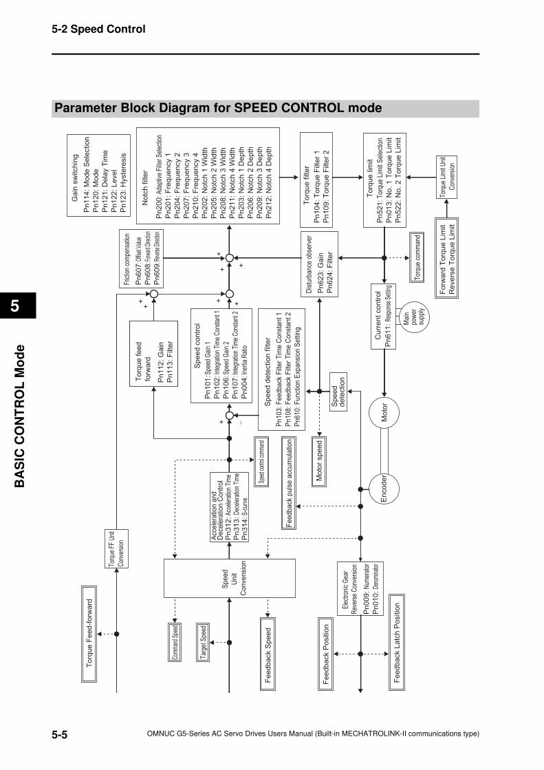
5-5
5-2 Speed Control
OMNUC G5-Series AC Servo Drives Users Manual (Built-in MECHATROLINK-II communications type)
5
BA
SIC
CO
NT
RO
L M
od
e
Parameter Block Diagram for SPEED CONTROL mode
Pn
10
4:
To
rqu
e F
ilte
r 1
Pn
10
9:
To
rqu
e F
ilte
r 2
Pn
52
1: T
orqu
e Li
mit
Sel
ectio
n
Pn
01
3:
No
. 1
To
rqu
e L
imit
Pn
52
2:
No
. 2
To
rqu
e L
imit
Pn
103
: F
eedback
Filt
er
Tim
e C
onst
ant
1
Pn
108
: F
eedback
Filt
er
Tim
e C
onst
ant
2
Pn
610
: F
unct
ion E
xpansi
on S
ett
ing
En
co
de
rM
oto
r
Mai
npo
wer
supp
ly
++
+
+
+
+
−
Pn
31
2:
Acce
lera
tion
Tim
eP
n3
13
: D
ecel
erat
ion
Tim
eP
n3
14
: S-
curv
e
Acc
ele
ratio
n a
nd
Dece
lera
tion C
ontr
ol
Pn
62
3:
Ga
in
Pn
62
4:
Filt
er
Dis
turb
ance
obs
erve
r
Pn
60
7: O
ffset
Valu
e
Pn
60
8: F
orward
Dire
ction
Pn
60
9: R
evers
e Dire
ction
Fric
tion
com
pens
atio
n
Pn
11
4:
Mo
de
Se
lectio
n
Pn
12
0:
Mo
de
Pn
12
1:
De
lay T
ime
Pn
12
2:
Le
ve
l
Pn
12
3:
Hyste
resis
Ga
in s
witch
ing
Pn
20
0: A
dapt
ive
Filte
r Sel
ectio
n
Pn
20
1:
Fre
qu
en
cy 1
Pn
20
4:
Fre
qu
en
cy 2
Pn
20
7:
Fre
qu
en
cy 3
Pn
21
0:
Fre
qu
en
cy 4
Pn
20
2:
No
tch
1 W
idth
Pn
20
5:
No
tch
2 W
idth
Pn
20
8:
No
tch
3 W
idth
Pn
21
1:
No
tch
4 W
idth
Pn
20
3:
No
tch
1 D
ep
th
Pn
20
6:
No
tch
2 D
ep
th
Pn
20
9:
No
tch
3 D
ep
th
Pn
21
2:
No
tch
4 D
ep
th
No
tch
filt
er
Pn
10
1: S
peed
Gai
n 1
Pn
10
2: I
nteg
ratio
n Ti
me
Con
stan
t 1
Pn
10
6: S
peed
Gai
n 2
Pn
10
7: I
nteg
ratio
n Ti
me
Con
stan
t 2
Pn
00
4: I
nerti
a R
atio
Sp
ee
d c
on
tro
l
To
rqu
e lim
it
Pn
61
1:
Resp
onse
Set
ting
Cu
rre
nt
co
ntr
ol
To
rqu
e f
ilte
r
Sp
ee
d d
ete
ctio
n f
ilte
r
Sp
ee
d
de
tectio
n
Spee
d con
trol c
omma
nd
Mo
tor
sp
ee
d
Tor
que
com
man
d
Feedback
puls
e a
ccum
ula
tion
Ele
ctro
nic
Gea
r
Rev
erse
Con
vers
ion
Pn
00
9:
Num
erat
or
Pn
01
0:
Deno
mina
tor
Fo
rwa
rd T
orq
ue
Lim
it
Re
ve
rse
To
rqu
e L
imit
Torq
ue L
imit
Uni
t
Con
vers
ion
Fe
ed
ba
ck P
ositio
n
Fe
ed
ba
ck L
atc
h P
ositio
n
++
Torq
ue F
F U
nit
Con
vers
ion
To
rqu
e F
ee
d-f
orw
ard
Sp
ee
d
Un
it
Co
nve
nsi
on
Com
man
d Sp
eed
Targ
et S
peed
Fe
ed
ba
ck S
pe
ed
To
rqu
e f
ee
d
forw
ard
Pn
11
2:
Ga
in
Pn
11
3:
Filt
er
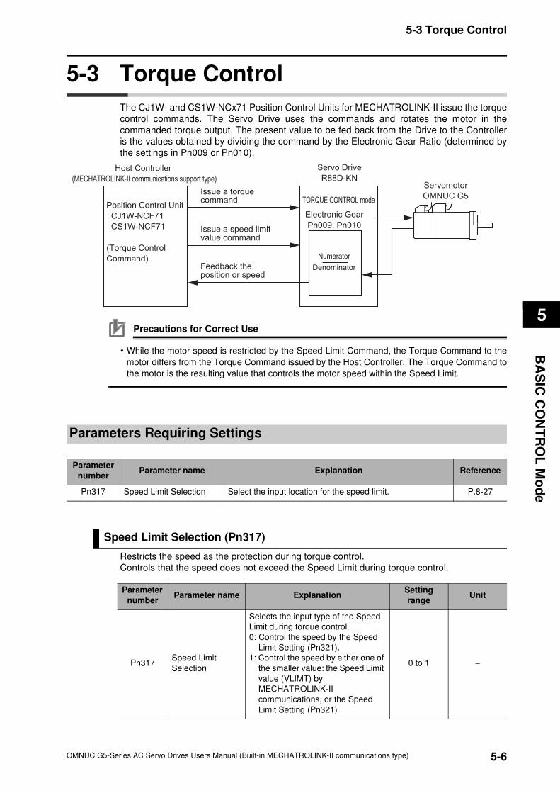
5-6
5-3 Torque Control
OMNUC G5-Series AC Servo Drives Users Manual (Built-in MECHATROLINK-II communications type)
5
BA
SIC
CO
NT
RO
L M
od
e
5-3 Torque Control
The CJ1W- and CS1W-NCx71 Position Control Units for MECHATROLINK-II issue the torque
control commands. The Servo Drive uses the commands and rotates the motor in the
commanded torque output. The present value to be fed back from the Drive to the Controller
is the values obtained by dividing the command by the Electronic Gear Ratio (determined by
the settings in Pn009 or Pn010).
Precautions for Correct Use
While the motor speed is restricted by the Speed Limit Command, the Torque Command to the
motor differs from the Torque Command issued by the Host Controller. The Torque Command to
the motor is the resulting value that controls the motor speed within the Speed Limit.
Parameters Requiring Settings
Speed Limit Selection (Pn317)
Restricts the speed as the protection during torque control.
Controls that the speed does not exceed the Speed Limit during torque control.
Servo Drive
R88D-KNServomotor
OMNUC G5
Host Controller
(MECHATROLINK-II communications support type)
Electronic Gear
Pn009, Pn010
TORQUE CONTROL modePosition Control Unit
CJ1W-NCF71
CS1W-NCF71
(Torque Control
Command)
Issue a torque command
Issue a speed limit value command
Feedback the position or speed
Numerator
Denominator
Parameter
numberParameter name Explanation Reference
Pn317 Speed Limit Selection Select the input location for the speed limit. P.8-27
Parameter
numberParameter name Explanation
Setting
rangeUnit
Pn317Speed Limit
Selection
Selects the input type of the Speed
Limit during torque control.
0: Control the speed by the Speed
Limit Setting (Pn321).
1: Control the speed by either one of
the smaller value: the Speed Limit
value (VLIMT) by
MECHATROLINK-II
communications, or the Speed
Limit Setting (Pn321)
0 to 1 −
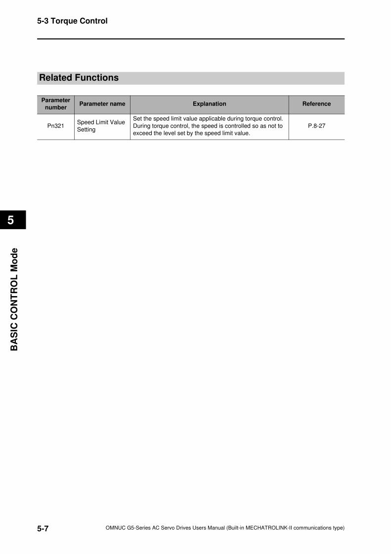
5-7
5-3 Torque Control
OMNUC G5-Series AC Servo Drives Users Manual (Built-in MECHATROLINK-II communications type)
5
BA
SIC
CO
NT
RO
L M
od
e
Related Functions
Parameter
number Parameter name Explanation Reference
Pn321Speed Limit Value
Setting
Set the speed limit value applicable during torque control.
During torque control, the speed is controlled so as not to
exceed the level set by the speed limit value.
P.8-27
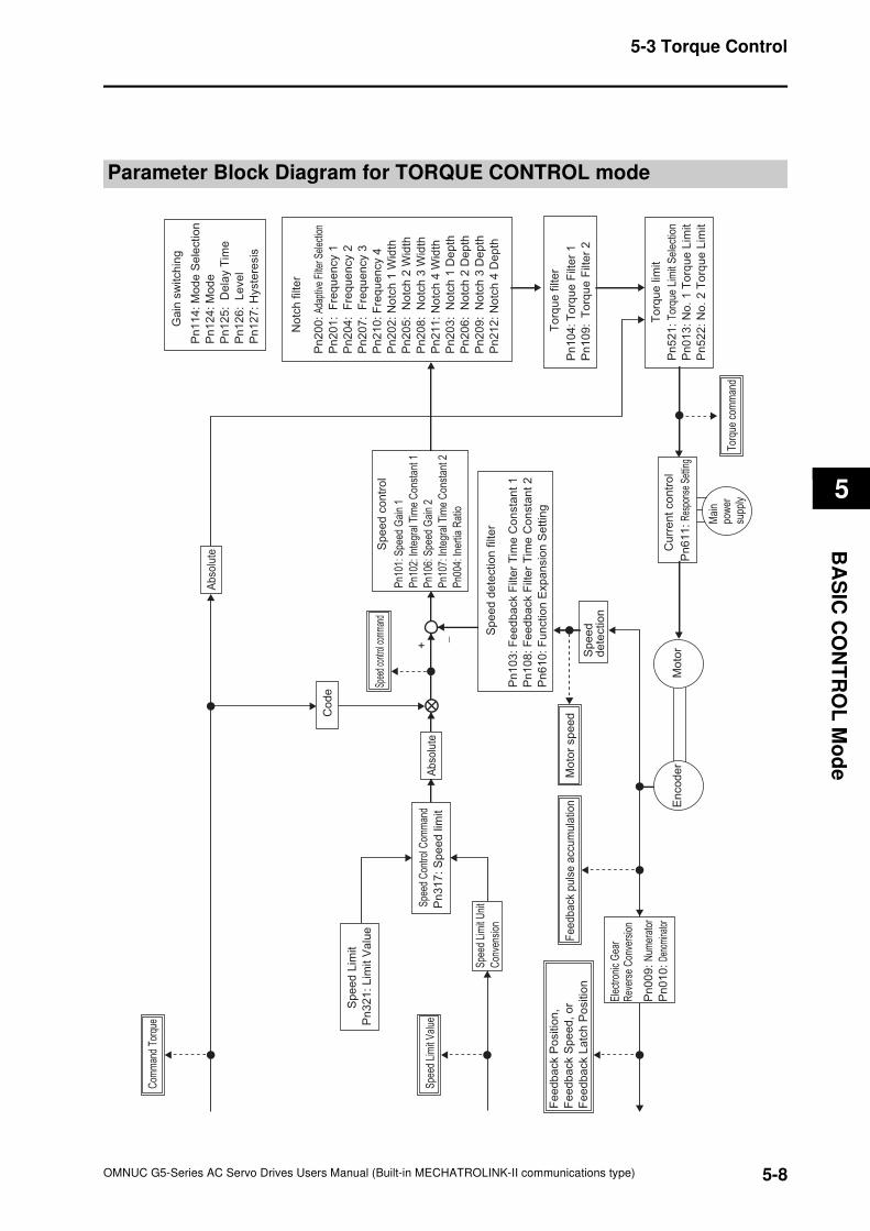
5-8
5-3 Torque Control
OMNUC G5-Series AC Servo Drives Users Manual (Built-in MECHATROLINK-II communications type)
5
BA
SIC
CO
NT
RO
L M
od
e
Parameter Block Diagram for TORQUE CONTROL mode
Pn
10
4: T
orq
ue
Filt
er
1
Pn
10
9: T
orq
ue
Filt
er
2
Pn
52
1:
Tor
que
Lim
it S
elec
tion
Pn
01
3:
No
. 1
To
rqu
e L
imit
Pn
52
2:
No
. 2
To
rqu
e L
imit
Pn
10
3:
Fe
ed
ba
ck F
ilte
r T
ime
Co
nsta
nt
1
Pn
10
8:
Fe
ed
ba
ck F
ilte
r T
ime
Co
nsta
nt
2
Pn
61
0:
Fu
nctio
n E
xp
an
sio
n S
ett
ing
En
co
de
rM
oto
r
Mai
npo
wer
supp
ly
Ele
ctro
nic
Gea
r R
ever
se C
onve
rsio
n
Ab
solu
te
Co
de
Pn
11
4:
Mo
de
Se
lectio
n
Pn
12
4:
Mo
de
Pn
12
5:
De
lay T
ime
Pn
12
6:
Le
ve
l
Pn
12
7:
Hyste
resis
Ga
in s
witch
ing
Pn
20
0:
Adap
tive
Filte
r Sel
ectio
n
Pn
20
1:
Fre
qu
en
cy 1
Pn
20
4:
Fre
qu
en
cy 2
Pn
20
7:
Fre
qu
en
cy 3
Pn
21
0:
Fre
qu
en
cy 4
Pn
20
2:
No
tch
1 W
idth
Pn
20
5:
No
tch
2 W
idth
Pn
20
8:
No
tch
3 W
idth
Pn
21
1:
No
tch
4 W
idth
Pn
20
3:
No
tch
1 D
ep
th
Pn
20
6:
No
tch
2 D
ep
th
Pn
20
9:
No
tch
3 D
ep
th
Pn
21
2:
No
tch
4 D
ep
th
No
tch
filt
er
Pn1
01: S
peed
Gai
n 1
Pn1
02: I
nteg
ral T
ime
Con
stan
t 1
Pn1
06: S
peed
Gai
n 2
Pn1
07: I
nteg
ral T
ime
Con
stan
t 2
Pn0
04: I
nert
ia R
atio
Sp
ee
d c
on
tro
l
To
rqu
e lim
it
Pn
61
1:
Res
pons
e Se
tting
Cu
rre
nt
co
ntr
ol
To
rqu
e f
ilte
r
Sp
ee
d d
ete
ctio
n f
ilte
r
Sp
ee
d
de
tectio
n
Spee
d co
ntro
l com
man
d
Mo
tor
sp
ee
d
Tor
que
com
man
d
Feedback
puls
e a
ccum
ula
tion
−
+
Pn
00
9:
Num
erat
or
Pn
01
0:
Deno
min
ator
Fe
ed
ba
ck P
ositio
n,
Fe
ed
ba
ck S
pe
ed
, o
r
Fe
ed
ba
ck L
atc
h P
ositio
n
Ab
solu
teP
n3
17
: S
pe
ed
lim
it
Spe
ed C
ontro
l Com
man
d
Pn
32
1:
Lim
it V
alu
e
Sp
ee
d L
imit
Spe
ed L
imit
Uni
t
Con
vens
ion
Spe
ed L
imit
Val
ue
Com
man
d To
rque
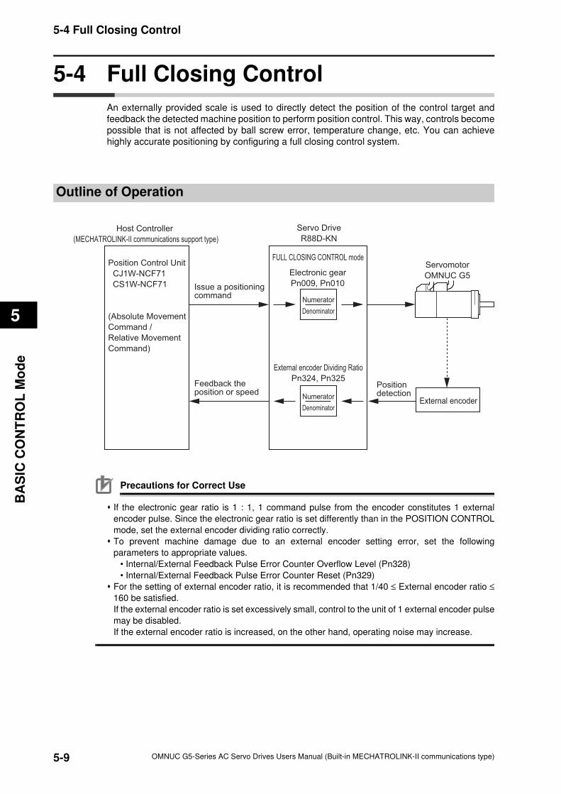
5-9
5-4 Full Closing Control
OMNUC G5-Series AC Servo Drives Users Manual (Built-in MECHATROLINK-II communications type)
5
BA
SIC
CO
NT
RO
L M
od
e
5-4 Full Closing Control
An externally provided scale is used to directly detect the position of the control target and
feedback the detected machine position to perform position control. This way, controls become
possible that is not affected by ball screw error, temperature change, etc. You can achieve
highly accurate positioning by configuring a full closing control system.
Outline of Operation
Precautions for Correct Use
If the electronic gear ratio is 1 : 1, 1 command pulse from the encoder constitutes 1 external
encoder pulse. Since the electronic gear ratio is set differently than in the POSITION CONTROL
mode, set the external encoder dividing ratio correctly.
To prevent machine damage due to an external encoder setting error, set the following
parameters to appropriate values.
• Internal/External Feedback Pulse Error Counter Overflow Level (Pn328)
• Internal/External Feedback Pulse Error Counter Reset (Pn329)
For the setting of external encoder ratio, it is recommended that 1/40 ≤ External encoder ratio ≤
160 be satisfied.
If the external encoder ratio is set excessively small, control to the unit of 1 external encoder pulse
may be disabled.
If the external encoder ratio is increased, on the other hand, operating noise may increase.
Servo Drive
R88D-KN
Servomotor
OMNUC G5
Host Controller
(MECHATROLINK-II communications support type)
FULL CLOSING CONTROL modePosition Control Unit
CJ1W-NCF71
CS1W-NCF71
(Absolute Movement
Command /
Relative Movement
Command)
Issue a positioning command
Feedback the position or speed
Electronic gear
Pn009, Pn010
Numerator
Denominator
External encoder
Positiondetection
External encoder Dividing Ratio
Pn324, Pn325
Numerator
Denominator

5-10
5-4 Full Closing Control
OMNUC G5-Series AC Servo Drives Users Manual (Built-in MECHATROLINK-II communications type)
5
BA
SIC
CO
NT
RO
L M
od
e
Parameters Requiring Settings
Rotation Direction Switching (Pn000)
Set the relation between the command direction and the motor rotation direction.
0: The +command indicates the forward direction as viewed from the shaft end (CCW)
1: The +command indicates the reverse direction as viewed from the shaft end (CW).
Take note that if Pn000 = 1, the scale count direction becomes opposite to the count direction
used for monitoring the total external encoder feedback pulses, etc.
CONTROL mode Selection (Pn001)
Select the full closing control (set value: 6).
Parameter
numberParameter name Explanation Reference
Pn000Rotation Direction
Switching
Set the relation between the command direction and the motor
rotation direction.P.8-1
Pn001CONTROL mode
Selection
Select the CONTROL mode.P.8-1
Pn009Electronic Gear
Ratio Numerator
Set the numerator of the electronic gear ratio for the command
pulse input.P.8-4
Pn010Electronic Gear
Ratio Denominator
Use this parameter to set the denominator of the electronic
gear ratio for the command pulse input.P.8-4
Pn323External Feedback
Pulse Type Selection
Select the external encoder type.P.8-28
Pn324
External Feedback
Pulse Dividing
Numerator
Set the numerator of the external encoder divider setting.
P.8-29
Pn325
External Feedback
Pulse Dividing
Denominator
Set the denominator of the external encoder divider setting.
P.8-29
Pn326
External Feedback
Pulse Direction
Switching
Set the polarity of the external encoder feedback pulse.
P.8-29
Pn327
External Feedback
Pulse Phase-Z
Setting
Set whether to enable or disable the disconnection detection
function of phase Z when a 90° phase difference output type
external encoder is used.
P.8-30
Pn328
Internal/External
Feedback Pulse Error
Counter Overflow Level
Set the threshold of A250 "internal/external feedback pulse
error counter overflow" in the command unit. P.8-30
Pn329
Internal/External
Feedback Pulse
Error Counter Reset
The hybrid error becomes 0 every time the motor rotates by the
set value. P.8-30
5-11
5-4 Full Closing Control
OMNUC G5-Series AC Servo Drives Users Manual (Built-in MECHATROLINK-II communications type)
5
BA
SIC
CO
NT
RO
L M
od
e
Electronic Gear Function (Pn009, Pn010)
This function sets the position command for the position control part a value calculated by
multiplying the pulse command input from the Host Controller with the set electronic gear ratio.
For details on the electronic gear function, refer to "6-6 Electronic Gear Function" (P.6-18).
External Feedback Pulse Type Selection (Pn323, Pn326)
Set the external encoder output type and direction.
Parameter
numberParameter name Explanation
Setting
rangeUnit
Pn009
Electronic Gear
Ratio Numerator
Set the numerator of the electronic
gear ratio for the command pulse
input.
0 to
1073741824−
Pn010
Electronic Gear
Ratio
Denominator
Set the denominator of the electronic
gear ratio for the command pulse
input.
0 to
1073741824−
Parameter
numberParameter name Explanation
Setting
rangeUnit
Pn323
External
Feedback Pulse
Type Selection
Select the type of the external
encoder to be used.
0: 90° phase difference output type
1: Serial communications
(Incremental encoder
specifications)
2: Serial communications (Absolute
encoder specifications)
0 to 2 −
Pn326
External
Feedback Pulse
Direction
Switching
If the count directions of the external
encoder feedback pulse and the
encoder total feedback pulses do not
match, set the reversal of the
external encoder feedback pulse
direction.
0: Not reversed, 1: Reversed
0 to 1 −
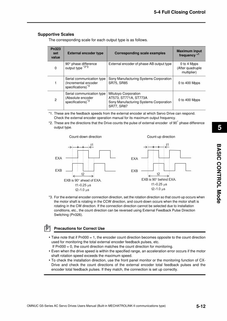
5-12
5-4 Full Closing Control
OMNUC G5-Series AC Servo Drives Users Manual (Built-in MECHATROLINK-II communications type)
5
BA
SIC
CO
NT
RO
L M
od
e
Supportive Scales
The corresponding scale for each output type is as follows.
*1. These are the feedback speeds from the external encoder at which Servo Drive can respond.
Check the external encoder operation manual for its maximum output frequency.
*2. These are the directions that the Drive counts the pulse of external encoder of 90° phase difference
output type.
*3. For the external encoder connection direction, set the rotation direction so that count-up occurs when
the motor shaft is rotating in the CCW direction, and count-down occurs when the motor shaft is
rotating in the CW direction. If the connection direction cannot be selected due to installation
conditions, etc., the count direction can be reversed using External Feedback Pulse Direction
Switching (Pn326).
Precautions for Correct Use
Take note that if Pn000 = 1, the encoder count direction becomes opposite to the count direction
used for monitoring the total external encoder feedback pulses, etc.
If Pn000 = 0, the count direction matches the count direction for monitoring.
Even when the drive speed is within the specified range, an acceleration error occurs if the motor
shaft rotation speed exceeds the maximum speed.
To check the installation direction, use the front panel monitor or the monitoring function of CX-
Drive and check the count directions of the external encoder total feedback pulses and the
encoder total feedback pulses. If they match, the connection is set up correctly.
Pn323
set
value
External encoder type Corresponding scale examplesMaximum input
frequency *1
0
90° phase difference
output type *2*3External encoder of phase-AB output type 0 to 4 Mpps
(After quadruple
multiplier)
1
Serial communication type
(Incremental encoder
specifications)*3
Sony Manufacturing Systems Corporation
SR75, SR85 0 to 400 Mpps
2
Serial communication type
(Absolute encoder
specifications)*3
Mitutoyo Corporation
AT573, ST771A, ST773A
Sony Manufacturing Systems Corporation
SR77, SR87
0 to 400 Mpps
Count-down direction Count-up direction
EXB is 90° ahead of EXA.
t1>0.25 µs
t2>1.0 µs
t1
t2
EXA
EXB
EXB is 90° behind EXA.
t1>0.25 µs
t2>1.0 µs
t1
t2
EXA
EXB
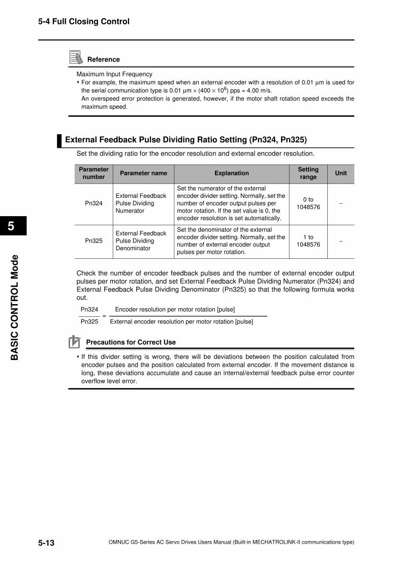
5-13
5-4 Full Closing Control
OMNUC G5-Series AC Servo Drives Users Manual (Built-in MECHATROLINK-II communications type)
5
BA
SIC
CO
NT
RO
L M
od
e
Reference
Maximum Input Frequency
For example, the maximum speed when an external encoder with a resolution of 0.01 µm is used for
the serial communication type is 0.01 µm × (400 × 106) pps = 4.00 m/s.
An overspeed error protection is generated, however, if the motor shaft rotation speed exceeds the
maximum speed.
External Feedback Pulse Dividing Ratio Setting (Pn324, Pn325)
Set the dividing ratio for the encoder resolution and external encoder resolution.
Check the number of encoder feedback pulses and the number of external encoder output
pulses per motor rotation, and set External Feedback Pulse Dividing Numerator (Pn324) and
External Feedback Pulse Dividing Denominator (Pn325) so that the following formula works
out.
Precautions for Correct Use
If this divider setting is wrong, there will be deviations between the position calculated from
encoder pulses and the position calculated from external encoder. If the movement distance is
long, these deviations accumulate and cause an internal/external feedback pulse error counter
overflow level error.
Parameter
numberParameter name Explanation
Setting
rangeUnit
Pn324
External Feedback
Pulse Dividing
Numerator
Set the numerator of the external
encoder divider setting. Normally, set the
number of encoder output pulses per
motor rotation. If the set value is 0, the
encoder resolution is set automatically.
0 to
1048576−
Pn325
External Feedback
Pulse Dividing
Denominator
Set the denominator of the external
encoder divider setting. Normally, set the
number of external encoder output
pulses per motor rotation.
1 to
1048576−
Pn324 Encoder resolution per motor rotation [pulse] =Pn325 External encoder resolution per motor rotation [pulse]
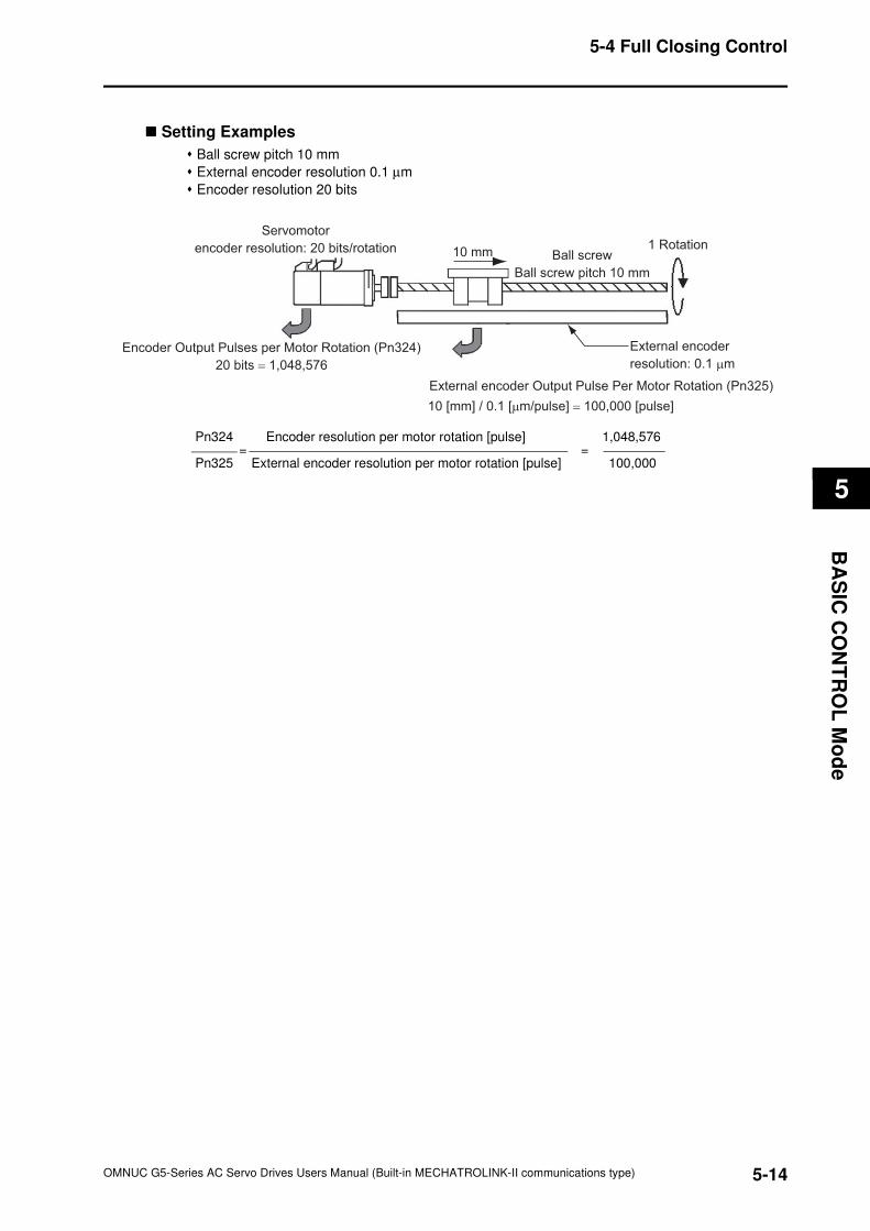
5-14
5-4 Full Closing Control
OMNUC G5-Series AC Servo Drives Users Manual (Built-in MECHATROLINK-II communications type)
5
BA
SIC
CO
NT
RO
L M
od
e
Setting Examples
Ball screw pitch 10 mm
External encoder resolution 0.1 µm
Encoder resolution 20 bits
Servomotor
encoder resolution: 20 bits/rotation 10 mm Ball screw
Ball screw pitch 10 mm
1 Rotation
External encoder
resolution: 0.1 µm
External encoder Output Pulse Per Motor Rotation (Pn325)
10 [mm] / 0.1 [µm/pulse] = 100,000 [pulse]
Encoder Output Pulses per Motor Rotation (Pn324)
20 bits = 1,048,576
Pn324 Encoder resolution per motor rotation [pulse] 1,048,576 = =Pn325 External encoder resolution per motor rotation [pulse] 100,000
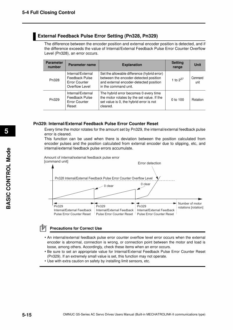
5-15
5-4 Full Closing Control
OMNUC G5-Series AC Servo Drives Users Manual (Built-in MECHATROLINK-II communications type)
5
BA
SIC
CO
NT
RO
L M
od
e
External Feedback Pulse Error Setting (Pn328, Pn329)
The difference between the encoder position and external encoder position is detected, and if
the difference exceeds the value of Internal/External Feedback Pulse Error Counter Overflow
Level (Pn328), an error occurs.
Pn329: Internal/External Feedback Pulse Error Counter Reset
Every time the motor rotates for the amount set by Pn329, the internal/external feedback pulse
error is cleared.
This function can be used when there is deviation between the position calculated from
encoder pulses and the position calculated from external encoder due to slipping, etc, and
internal/external feedback pulse errors accumulate.
Precautions for Correct Use
An internal/external feedback pulse error counter overflow level error occurs when the external
encoder is abnormal, connection is wrong, or connection point between the motor and load is
loose, among others. Accordingly, check these items when an error occurs.
Be sure to set an appropriate value for Internal/External Feedback Pulse Error Counter Reset
(Pn329). If an extremely small value is set, this function may not operate.
Use with extra caution on safety by installing limit sensors, etc.
Parameter
numberParameter name Explanation
Setting
rangeUnit
Pn328
Internal/External
Feedback Pulse
Error Counter
Overflow Level
Set the allowable difference (hybrid error)
between the encoder-detected position
and external encoder-detected position
in the command unit.
1 to 227 Command
unit
Pn329
Internal/External
Feedback Pulse
Error Counter
Reset
The hybrid error becomes 0 every time
the motor rotates by the set value. If the
set value is 0, the hybrid error is not
cleared.
0 to 100 Rotation
Amount of internal/external feedback pulse error[command unit]
Error detection
Pn328 Internal/External Feedback Pulse Error Counter Overflow Level
Pn329
Internal/External Feedback
Pulse Error Counter Reset
Pn329
Internal/External Feedback
Pulse Error Counter Reset
Pn329
Internal/External Feedback
Pulse Error Counter Reset
Number of motor
rotations [rotation]
0 clear0 clear
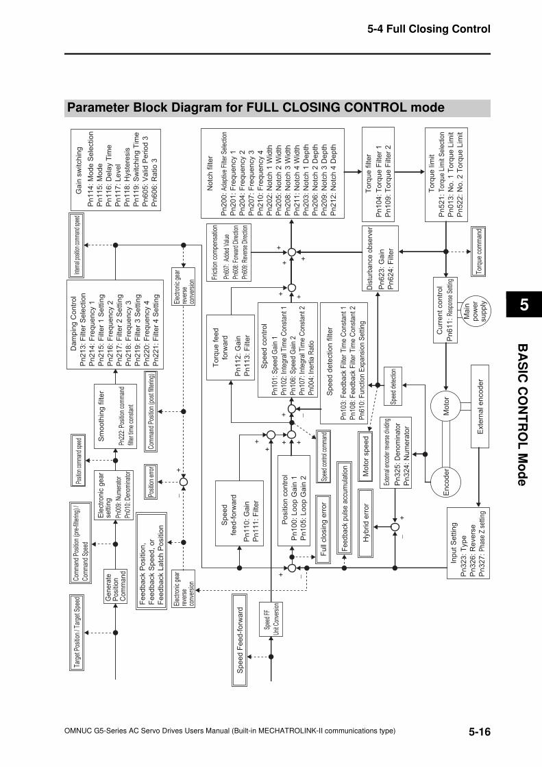
5-16
5-4 Full Closing Control
OMNUC G5-Series AC Servo Drives Users Manual (Built-in MECHATROLINK-II communications type)
5
BA
SIC
CO
NT
RO
L M
od
e
Parameter Block Diagram for FULL CLOSING CONTROL mode
Pn
10
4: T
orq
ue
Filt
er
1
Pn
10
9: T
orq
ue
Filt
er
2
Pn
52
1:
Tor
que
Lim
it S
elec
tion
Pn
01
3:
No
. 1
To
rqu
e L
imit
Pn
52
2:
No
. 2
To
rqu
e L
imit
Pn
103
: F
eedb
ack
Filt
er
Tim
e C
on
stant 1
Pn
108
: F
ee
dback
Filt
er
Tim
e C
on
stant 2
Pn
610
: F
unct
ion E
xpa
nsi
on S
ettin
g
En
co
de
rM
oto
r
Ma
inp
ow
er
su
pp
ly
+
+
++
+
+
+
+ +−
−
−
+
−
Pn
10
0: L
oo
p G
ain
1
Pn
10
5: L
oo
p G
ain
2
Po
sitio
n c
on
tro
l
Pn
11
2: G
ain
Pn
11
3:
Filt
er
To
rqu
e f
ee
d
forw
ard
Pn
62
3: G
ain
Pn
62
4:
Filt
er
Dis
turb
ance
obse
rver
Pn60
7: A
dded
Val
ue
Pn60
8: F
orw
ard
Dire
ctio
n
Pn60
9: R
ever
se D
irect
ion
Fric
tion
com
pens
atio
n
Pn
11
4:
Mo
de
Se
lectio
n
Pn
11
5: M
od
e
Pn
11
6: D
ela
y T
ime
Pn
11
7: L
eve
l
Pn
11
8: H
yste
resis
Pn
11
9: S
witch
ing
Tim
e
Pn
60
5:
Va
lid P
erio
d 3
Pn
60
6:
Ra
tio
3
Ga
in s
witch
ing
Pn
20
0:
Ada
ptiv
e Fi
lter S
elec
tion
Pn
20
1:
Fre
qu
en
cy 1
Pn
20
4:
Fre
qu
en
cy 2
Pn
20
7:
Fre
qu
en
cy 3
Pn
21
0:
Fre
qu
en
cy 4
Pn
20
2:
No
tch
1 W
idth
Pn
20
5:
No
tch
2 W
idth
Pn
20
8:
No
tch
3 W
idth
Pn
21
1:
No
tch
4 W
idth
Pn
20
3:
No
tch
1 D
ep
th
Pn
20
6:
No
tch
2 D
ep
th
Pn
20
9:
No
tch
3 D
ep
th
Pn
21
2:
No
tch
4 D
ep
th
No
tch
filt
er
Pn
101
: S
peed G
ain
1
Pn
102
: In
tegra
l Tim
e C
onst
ant 1
Pn
106
: S
peed G
ain
2
Pn
107
: In
tegra
l Tim
e C
onst
ant 2
Pn
004
: In
ert
ia R
atio
Sp
ee
d c
on
tro
l
To
rqu
e lim
it
Pn
61
1:
Res
pons
e Se
tting
Cu
rre
nt
co
ntr
ol
Pn
32
3: T
yp
e
Pn
32
6: R
eve
rse
Pn
32
7:
Pha
se Z
set
ting
Inp
ut
Se
ttin
g
Pn
32
5:
De
no
min
ato
r
Pn
32
4: N
um
era
tor
Exte
rnal
enc
oder
reve
rse
divid
ing
Elec
troni
c ge
arre
vers
e co
nver
sion
To
rqu
e f
ilte
r
Sp
ee
d d
ete
ctio
n f
ilte
r
Spee
d de
tect
ion
Exte
rna
l e
nco
de
r
Posi
tion
erro
r
Fu
ll clo
sin
g e
rro
rSp
eed
cont
rol c
omm
and
Mo
tor
sp
ee
d
Tor
que
com
man
d
Inter
nal p
ositio
n com
mand
spee
d
Hyb
rid
err
or
Fee
dback
puls
e a
ccu
mula
tion+
Posit
ion co
mman
d spe
ed
Sp
ee
d
fee
d-f
orw
ard
Pn
11
0: G
ain
Pn
11
1:
Filt
er
+
+Sp
eed
FF
Unit
Conv
ersio
n
Sp
ee
d F
ee
d-f
orw
ard
Elec
troni
c ge
arre
vers
e co
nver
sion
Pn22
2: P
ositi
on c
omm
and
filte
r tim
e co
nsta
nt
Sm
oo
thin
g f
ilte
r
Pn00
9: N
umer
ator
Pn01
0: D
enom
inat
or
Ele
ctro
nic
ge
ar
settin
g
Com
man
d Po
sitio
n (p
ost f
ilter
ing)
Pn
21
3:
Filt
er
Se
lectio
n
Pn
21
4:
Fre
qu
en
cy 1
Pn
21
5:
Filt
er
1 S
ett
ing
Pn
21
6:
Fre
qu
en
cy 2
Pn
21
7:
Filt
er
2 S
ett
ing
Pn
21
8:
Fre
qu
en
cy 3
Pn
21
9:
Filt
er
3 S
ett
ing
Pn
22
0:
Fre
qu
en
cy 4
Pn
22
1:
Filt
er
4 S
ett
ing
Da
mp
ing
Co
ntr
ol
Fe
ed
ba
ck P
ositio
n,
Fe
ed
ba
ck S
pe
ed
, o
r
Fe
ed
ba
ck L
atc
h P
ositio
n
Com
man
d Po
sitio
n (p
re-fi
lterin
g) /
Com
man
d Sp
eed
Ge
ne
rate
P
osi
tion
C
om
ma
nd
Targ
et P
ositi
on /
Targ
et S
peed

OMNUC G5-Series AC Servo Drives Users Manual (Built-in MECHATROLINK-II communications type)
6
6
Accurax
This chapter gives outline of applied functions such as electronic gears, gain
switching and soft start, and explains the setting contents.
6-1 Sequence I/O Signal .....................................................6-1
6-2 Forward and Reverse Drive Prohibition Functions ...6-6
6-3 Overrun Protection .......................................................6-9
6-4 Backlash Compensation ............................................6-11
6-5 Brake Interlock............................................................6-13
6-6 Electronic Gear Function ...........................................6-18
6-7 Torque Limit Switching..............................................6-21
6-8 Soft Start......................................................................6-23
6-9 Gain Switching Function............................................6-25
6-10 Gain Switching 3 Function.........................................6-36
Applied Functions
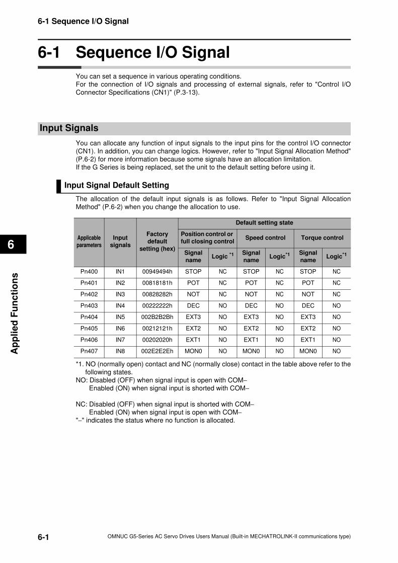
6-1
6-1 Sequence I/O Signal
OMNUC G5-Series AC Servo Drives Users Manual (Built-in MECHATROLINK-II communications type)
6
Ap
pli
ed
Fu
nc
tio
ns
6-1 Sequence I/O Signal
You can set a sequence in various operating conditions.
For the connection of I/O signals and processing of external signals, refer to "Control I/O
Connector Specifications (CN1)" (P.3-13).
Input Signals
You can allocate any function of input signals to the input pins for the control I/O connector
(CN1). In addition, you can change logics. However, refer to "Input Signal Allocation Method"
(P.6-2) for more information because some signals have an allocation limitation.
If the G Series is being replaced, set the unit to the default setting before using it.
Input Signal Default Setting
The allocation of the default input signals is as follows. Refer to "Input Signal Allocation
Method" (P.6-2) when you change the allocation to use.
*1. NO (normally open) contact and NC (normally close) contact in the table above refer to the
following states.
NO: Disabled (OFF) when signal input is open with COM−
Enabled (ON) when signal input is shorted with COM−
NC: Disabled (OFF) when signal input is shorted with COM−
Enabled (ON) when signal input is open with COM−
"−" indicates the status where no function is allocated.
Applicable
parameters
Input
signals
Factory
default
setting (hex)
Default setting state
Position control or
full closing controlSpeed control Torque control
Signal
nameLogic *1
Signal
nameLogic*1 Signal
nameLogic*1
Pn400 IN1 00949494h STOP NC STOP NC STOP NC
Pn401 IN2 00818181h POT NC POT NC POT NC
Pn402 IN3 00828282h NOT NC NOT NC NOT NC
Pn403 IN4 00222222h DEC NO DEC NO DEC NO
Pn404 IN5 002B2B2Bh EXT3 NO EXT3 NO EXT3 NO
Pn405 IN6 00212121h EXT2 NO EXT2 NO EXT2 NO
Pn406 IN7 00202020h EXT1 NO EXT1 NO EXT1 NO
Pn407 IN8 002E2E2Eh MON0 NO MON0 NO MON0 NO
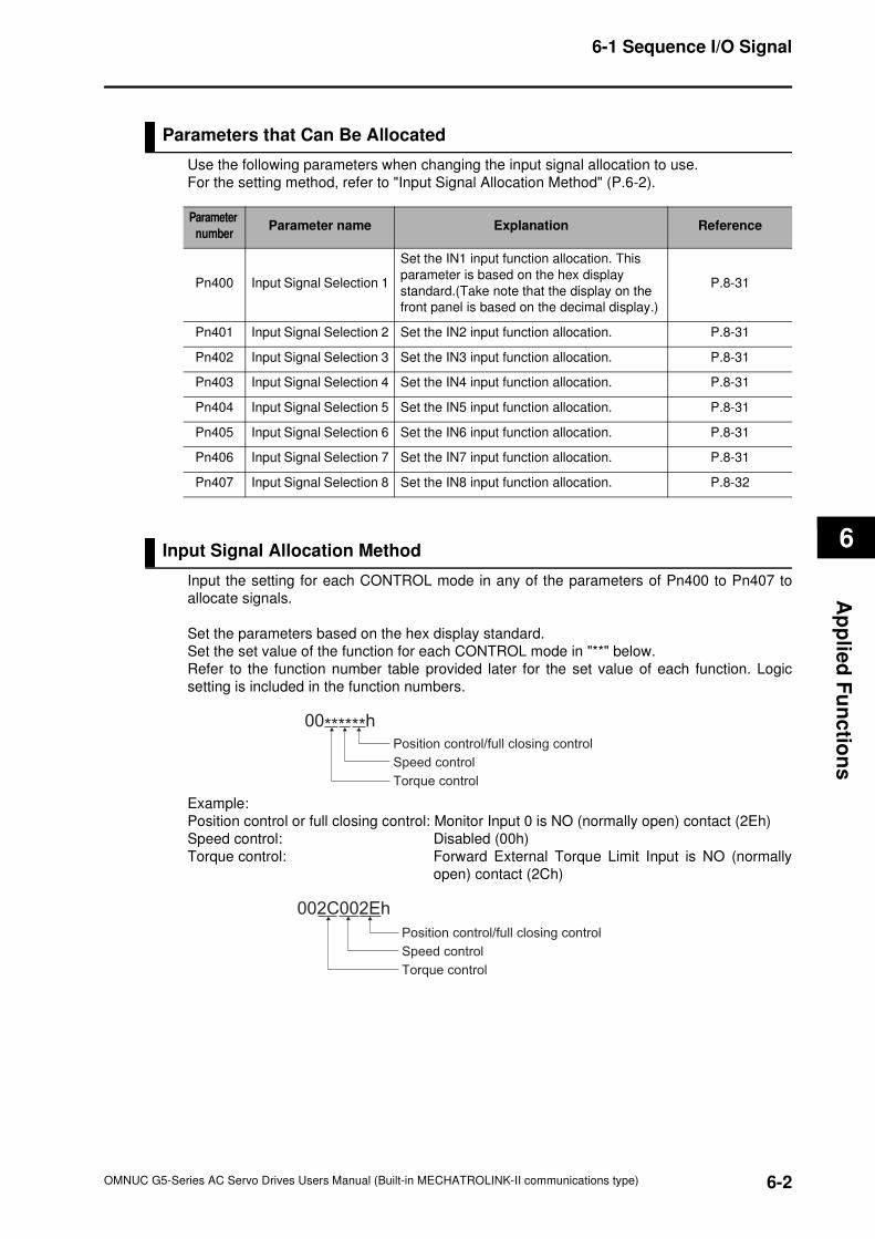
6
6-2
6-1 Sequence I/O Signal
OMNUC G5-Series AC Servo Drives Users Manual (Built-in MECHATROLINK-II communications type)
Ap
plie
d F
un
ctio
ns
Parameters that Can Be Allocated
Use the following parameters when changing the input signal allocation to use.
For the setting method, refer to "Input Signal Allocation Method" (P.6-2).
Input Signal Allocation Method
Input the setting for each CONTROL mode in any of the parameters of Pn400 to Pn407 to
allocate signals.
Set the parameters based on the hex display standard.
Set the set value of the function for each CONTROL mode in "**" below.
Refer to the function number table provided later for the set value of each function. Logic
setting is included in the function numbers.
Example:
Position control or full closing control: Monitor Input 0 is NO (normally open) contact (2Eh)
Speed control: Disabled (00h)
Torque control: Forward External Torque Limit Input is NO (normally
open) contact (2Ch)
Parameter
numberParameter name Explanation Reference
Pn400 Input Signal Selection 1
Set the IN1 input function allocation. This
parameter is based on the hex display
standard.(Take note that the display on the
front panel is based on the decimal display.)
P.8-31
Pn401 Input Signal Selection 2 Set the IN2 input function allocation. P.8-31
Pn402 Input Signal Selection 3 Set the IN3 input function allocation. P.8-31
Pn403 Input Signal Selection 4 Set the IN4 input function allocation. P.8-31
Pn404 Input Signal Selection 5 Set the IN5 input function allocation. P.8-31
Pn405 Input Signal Selection 6 Set the IN6 input function allocation. P.8-31
Pn406 Input Signal Selection 7 Set the IN7 input function allocation. P.8-31
Pn407 Input Signal Selection 8 Set the IN8 input function allocation. P.8-32
00******h
Position control/full closing control
Speed control
Torque control
002C002Eh
Position control/full closing control
Speed control
Torque control
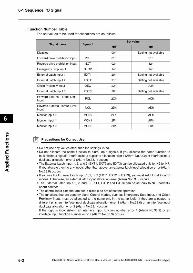
6-3
6-1 Sequence I/O Signal
OMNUC G5-Series AC Servo Drives Users Manual (Built-in MECHATROLINK-II communications type)
6
Ap
pli
ed
Fu
nc
tio
ns
Function Number Table
The set values to be used for allocations are as follows.
Precautions for Correct Use
Do not use any values other than the settings listed.
Do not allocate the same function to plural input signals. If you allocate the same function to
multiple input signals, interface input duplicate allocation error 1 (Alarm No.33.0) or interface input
duplicate allocation error 2 (Alarm No.33.1) occurs.
The External Latch Input 1, 2, and 3 (EXT1, EXT2 and EXT3) can be allocated only to IN5 to IN7.
If you allocate them to any inputs other than above, an external latch input allocation error (Alarm
No.33.8) occurs.
If you use the External Latch Input 1, 2, or 3 (EXT1, EXT2 or EXT3), you must set it for all Control
modes. Otherwise, an external latch input allocation error (Alarm No.33.8) occurs.
The External Latch Input 1, 2, and 3 (EXT1, EXT2 and EXT3) can be set only to NO (normally
open) contact.
The control input pins that are set to disable do not affect the operation.
The functions that are used by plural Control modes, such as Emergency Stop Input, and Origin
Proximity Input, must be allocated to the same pin, in the same logic. If they are allocated to
different pins, an interface input duplicate allocation error 1 (Alarm No.33.0) or an interface input
duplicate allocation error 2 (Alarm No.33.1) occurs.
If the logic is inconsistent, an interface input function number error 1 (Alarm No.33.2) or an
interface input function number error 2 (Alarm No.33.3) occurs.
Signal name SymbolSet value
NO NC
Disabled − 00h Setting not available
Forward drive prohibition input POT 01h 81h
Reverse drive prohibition input NOT 02h 82h
Emergency Stop Input STOP 14h 94h
External Latch Input 1 EXT1 20h Setting not available
External Latch Input 2 EXT2 21h Setting not available
Origin Proximity Input DEC 22h A2h
External Latch Input 3 EXT3 28h Setting not available
Forward External Torque Limit
InputPCL 2Ch ACh
Reverse External Torque Limit
InputNCL 2Dh ADh
Monitor Input 0 MON0 2Eh AEh
Monitor Input 1 MON1 2Fh AFh
Monitor Input 2 MON2 30h B0h
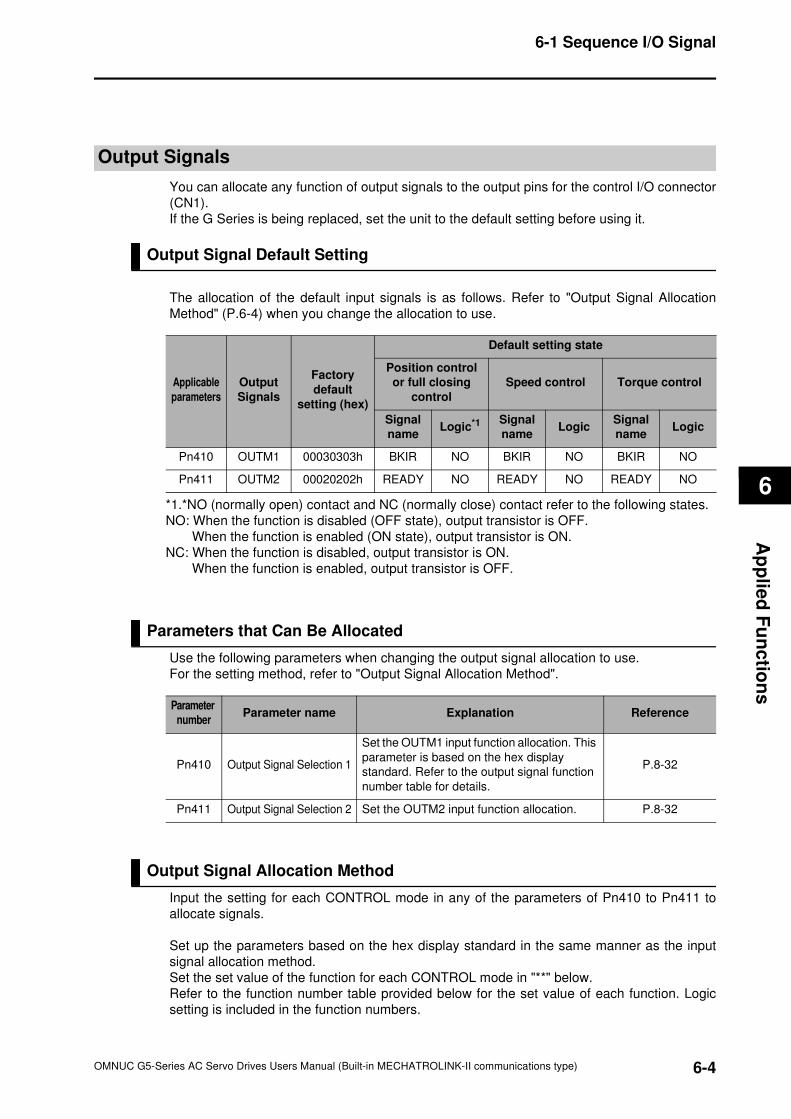
6
6-4
6-1 Sequence I/O Signal
OMNUC G5-Series AC Servo Drives Users Manual (Built-in MECHATROLINK-II communications type)
Ap
plie
d F
un
ctio
ns
Output Signals
You can allocate any function of output signals to the output pins for the control I/O connector
(CN1).
If the G Series is being replaced, set the unit to the default setting before using it.
Output Signal Default Setting
The allocation of the default input signals is as follows. Refer to "Output Signal Allocation
Method" (P.6-4) when you change the allocation to use.
Parameters that Can Be Allocated
Use the following parameters when changing the output signal allocation to use.
For the setting method, refer to "Output Signal Allocation Method".
Output Signal Allocation Method
Input the setting for each CONTROL mode in any of the parameters of Pn410 to Pn411 to
allocate signals.
Set up the parameters based on the hex display standard in the same manner as the input
signal allocation method.
Set the set value of the function for each CONTROL mode in "**" below.
Refer to the function number table provided below for the set value of each function. Logic
setting is included in the function numbers.
Applicable
parameters
Output
Signals
Factory
default
setting (hex)
Default setting state
Position control
or full closing
control
Speed control Torque control
Signal
nameLogic*1 Signal
nameLogic
Signal
nameLogic
Pn410 OUTM1 00030303h BKIR NO BKIR NO BKIR NO
Pn411 OUTM2 00020202h READY NO READY NO READY NO
*1.*NO (normally open) contact and NC (normally close) contact refer to the following states.
NO: When the function is disabled (OFF state), output transistor is OFF.
When the function is enabled (ON state), output transistor is ON.
NC: When the function is disabled, output transistor is ON.
When the function is enabled, output transistor is OFF.
Parameter
numberParameter name Explanation Reference
Pn410 Output Signal Selection 1
Set the OUTM1 input function allocation. This
parameter is based on the hex display
standard. Refer to the output signal function
number table for details.
P.8-32
Pn411 Output Signal Selection 2 Set the OUTM2 input function allocation. P.8-32
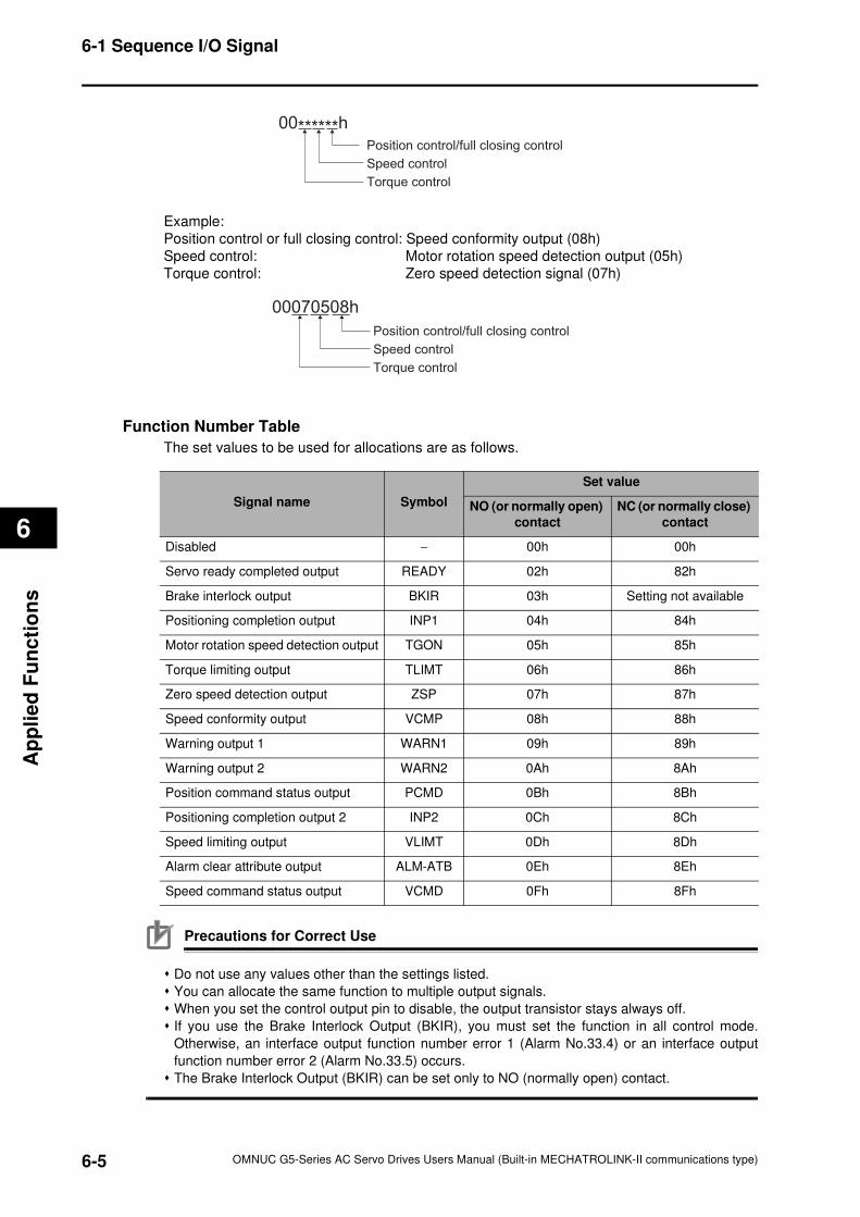
6-5
6-1 Sequence I/O Signal
OMNUC G5-Series AC Servo Drives Users Manual (Built-in MECHATROLINK-II communications type)
6
Ap
pli
ed
Fu
nc
tio
ns
Example:
Position control or full closing control: Speed conformity output (08h)
Speed control: Motor rotation speed detection output (05h)
Torque control: Zero speed detection signal (07h)
Function Number Table
The set values to be used for allocations are as follows.
Precautions for Correct Use
Do not use any values other than the settings listed.
You can allocate the same function to multiple output signals.
When you set the control output pin to disable, the output transistor stays always off.
If you use the Brake Interlock Output (BKIR), you must set the function in all control mode.
Otherwise, an interface output function number error 1 (Alarm No.33.4) or an interface output
function number error 2 (Alarm No.33.5) occurs.
The Brake Interlock Output (BKIR) can be set only to NO (normally open) contact.
00******h
Position control/full closing control
Speed control
Torque control
00070508h
Position control/full closing control
Speed control
Torque control
Signal name Symbol
Set value
NO (or normally open)
contact
NC (or normally close)
contact
Disabled − 00h 00h
Servo ready completed output READY 02h 82h
Brake interlock output BKIR 03h Setting not available
Positioning completion output INP1 04h 84h
Motor rotation speed detection output TGON 05h 85h
Torque limiting output TLIMT 06h 86h
Zero speed detection output ZSP 07h 87h
Speed conformity output VCMP 08h 88h
Warning output 1 WARN1 09h 89h
Warning output 2 WARN2 0Ah 8Ah
Position command status output PCMD 0Bh 8Bh
Positioning completion output 2 INP2 0Ch 8Ch
Speed limiting output VLIMT 0Dh 8Dh
Alarm clear attribute output ALM-ATB 0Eh 8Eh
Speed command status output VCMD 0Fh 8Fh
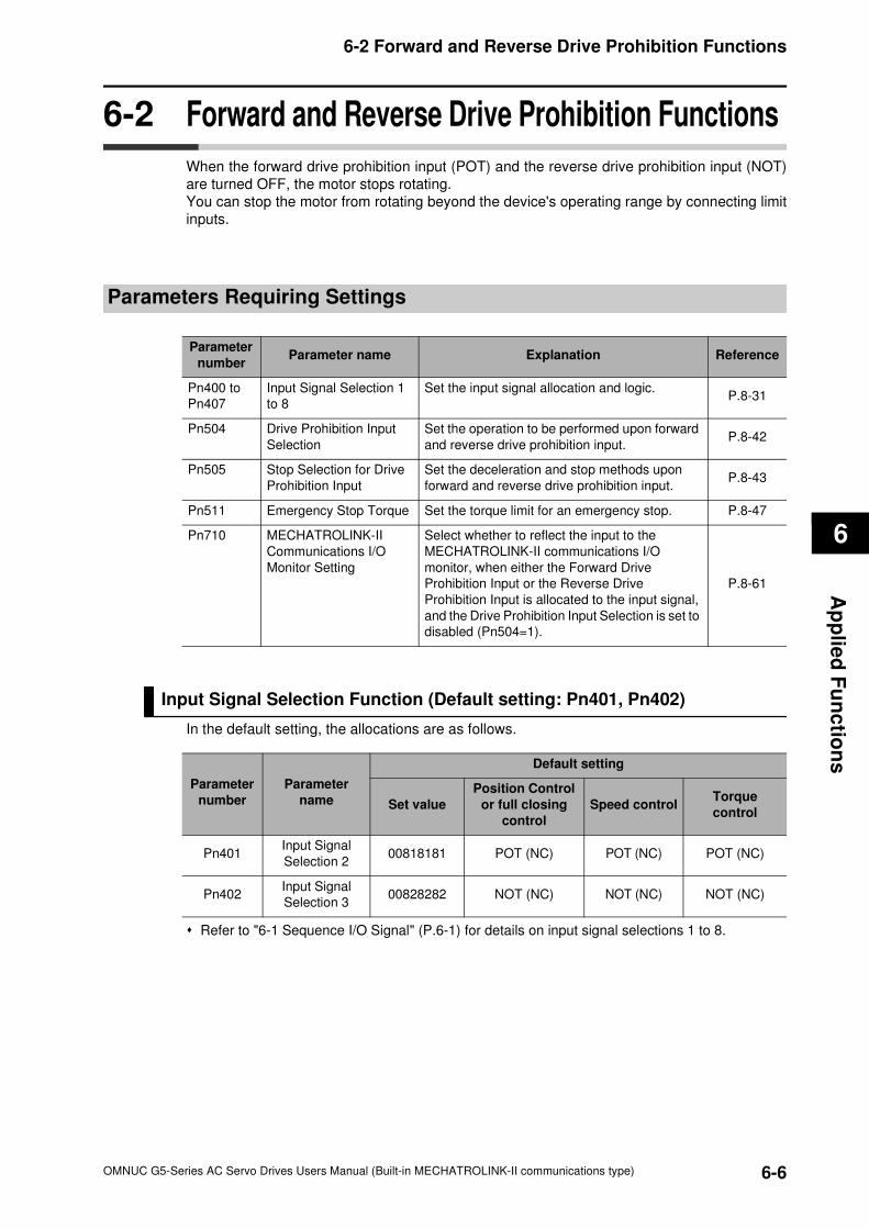
6
6-6
6-2 Forward and Reverse Drive Prohibition Functions
OMNUC G5-Series AC Servo Drives Users Manual (Built-in MECHATROLINK-II communications type)
Ap
plie
d F
un
ctio
ns
6-2 Forward and Reverse Drive Prohibition Functions
When the forward drive prohibition input (POT) and the reverse drive prohibition input (NOT)
are turned OFF, the motor stops rotating.
You can stop the motor from rotating beyond the device's operating range by connecting limit
inputs.
Parameters Requiring Settings
Input Signal Selection Function (Default setting: Pn401, Pn402)
In the default setting, the allocations are as follows.
Refer to "6-1 Sequence I/O Signal" (P.6-1) for details on input signal selections 1 to 8.
Parameter
numberParameter name Explanation Reference
Pn400 to
Pn407
Input Signal Selection 1
to 8
Set the input signal allocation and logic.P.8-31
Pn504 Drive Prohibition Input
Selection
Set the operation to be performed upon forward
and reverse drive prohibition input.P.8-42
Pn505 Stop Selection for Drive
Prohibition Input
Set the deceleration and stop methods upon
forward and reverse drive prohibition input.P.8-43
Pn511 Emergency Stop Torque Set the torque limit for an emergency stop. P.8-47
Pn710 MECHATROLINK-II
Communications I/O
Monitor Setting
Select whether to reflect the input to the
MECHATROLINK-II communications I/O
monitor, when either the Forward Drive
Prohibition Input or the Reverse Drive
Prohibition Input is allocated to the input signal,
and the Drive Prohibition Input Selection is set to
disabled (Pn504=1).
P.8-61
Parameter
number
Parameter
name
Default setting
Set value
Position Control
or full closing
control
Speed controlTorque
control
Pn401Input Signal
Selection 200818181 POT (NC) POT (NC) POT (NC)
Pn402Input Signal
Selection 300828282 NOT (NC) NOT (NC) NOT (NC)
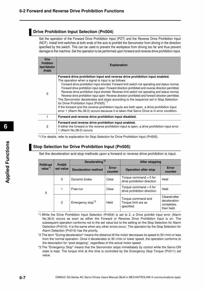
6-7
6-2 Forward and Reverse Drive Prohibition Functions
OMNUC G5-Series AC Servo Drives Users Manual (Built-in MECHATROLINK-II communications type)
6
Ap
pli
ed
Fu
nc
tio
ns
Drive Prohibition Input Selection (Pn504)
Set the operation of the Forward Drive Prohibition Input (POT) and the Reverse Drive Prohibition Input
(NOT). Install limit switches at both ends of the axis to prohibit the Servomotor from driving in the direction
specified by the switch. This can be used to prevent the workpiece from driving too far and thus prevent
damage to the machine. Set the operation to be performed upon forward and reverse drive prohibition input.
Stop Selection for Drive Prohibition Input (Pn505)
Set the deceleration and stop methods upon a forward or reverse drive prohibition is input.
Drive
Prohibition
Input Selection
(Pn504)
Explanation
0
Forward drive prohibition input and reverse drive prohibition input enabled.
The operation when a signal is input is as follows.
Forward drive prohibition input shorted: Forward limit switch not operating and status normal.
Forward drive prohibition input open: Forward direction prohibited and reverse direction permitted.
Reverse drive prohibition input shorted: Reverse limit switch not operating and status normal.
Reverse drive prohibition input open: Reverse direction prohibited and forward direction permitted.
The Servomotor decelerates and stops according to the sequence set in Stop Selection
for Drive Prohibition Input (Pn505).*1
If the forward and the reverse prohibition inputs are both open, a drive prohibition input
error 1 (Alarm No.38.0) occurs because it is taken that Servo Drive is in error condition.
1 Forward and reverse drive prohibition input disabled.
2
Forward and reverse drive prohibition input enabled.
If either the forward or the reverse prohibition input is open, a drive prohibition input error
1 (Alarm No.38.0) occurs.
*1.For details, refer to explanation for Stop Selection for Drive Prohibition Input (Pn505).
Pn504 set
value*1Pn505
set value
Decelerating*2 After stopping
Deceleration methodError
counterOperation after stop
Error
counter
0
0 Dynamic brake ClearTorque command = 0 for
drive prohibition directionHeld
1 Free-run ClearTorque command = 0 for
drive prohibition directionHeld
2 Emergency stop*3 Held
Torque command and
Torque limit are as
specified.
Cleared after
deceleration
completes,
then held.
*1.While the Drive Prohibition Input Selection (Pn504) is set to 2, a Drive prohibit input error (Alarm
No.38.0) occurs as soon as either the Forward or Reverse Drive Prohibition Input is on. The
subsequent operation conforms not to the set value but to the setting on the Stop Selection for Alarm
Detection (Pn510). It is the same when any other errors occur. The operation by the Stop Selection for
Alarm Detection (Pn510) has the priority.
*2.The term "During deceleration" means the distance till the motor decreases its speed to 30 r/min or less
from the normal operation. Once it decelerates to 30 r/min or lower speed, the operation conforms to
the description for “post-stopping”, regardless of the actual motor speed.
*3.The "Emergency Stop" means that the Servomotor stops immediately by control while the Servo-ON
state is kept. The torque limit at this time is controlled by the Emergency Stop Torque (Pn511) set
value.
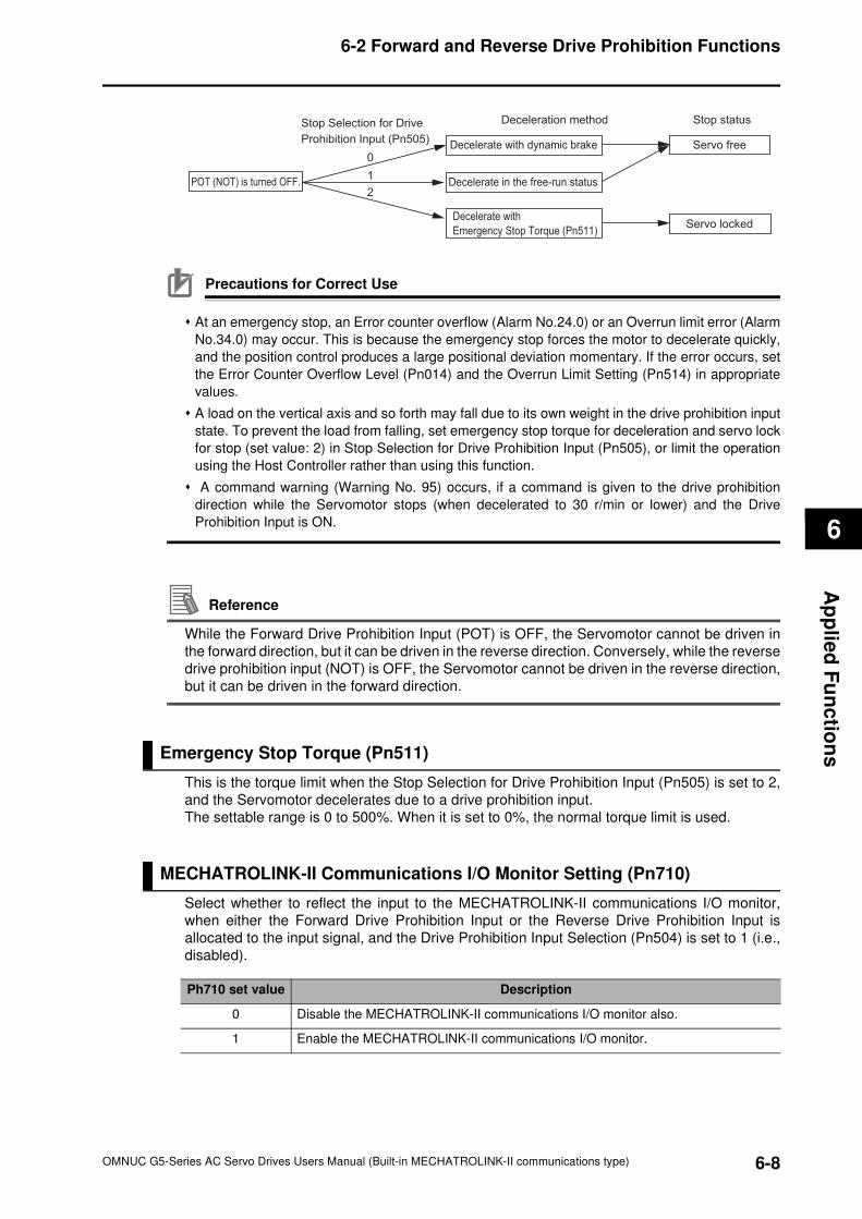
6
6-8
6-2 Forward and Reverse Drive Prohibition Functions
OMNUC G5-Series AC Servo Drives Users Manual (Built-in MECHATROLINK-II communications type)
Ap
plie
d F
un
ctio
ns
Precautions for Correct Use
At an emergency stop, an Error counter overflow (Alarm No.24.0) or an Overrun limit error (Alarm
No.34.0) may occur. This is because the emergency stop forces the motor to decelerate quickly,
and the position control produces a large positional deviation momentary. If the error occurs, set
the Error Counter Overflow Level (Pn014) and the Overrun Limit Setting (Pn514) in appropriate
values.
A load on the vertical axis and so forth may fall due to its own weight in the drive prohibition input
state. To prevent the load from falling, set emergency stop torque for deceleration and servo lock
for stop (set value: 2) in Stop Selection for Drive Prohibition Input (Pn505), or limit the operation
using the Host Controller rather than using this function.
A command warning (Warning No. 95) occurs, if a command is given to the drive prohibition
direction while the Servomotor stops (when decelerated to 30 r/min or lower) and the Drive
Prohibition Input is ON.
Reference
While the Forward Drive Prohibition Input (POT) is OFF, the Servomotor cannot be driven in
the forward direction, but it can be driven in the reverse direction. Conversely, while the reverse
drive prohibition input (NOT) is OFF, the Servomotor cannot be driven in the reverse direction,
but it can be driven in the forward direction.
Emergency Stop Torque (Pn511)
This is the torque limit when the Stop Selection for Drive Prohibition Input (Pn505) is set to 2,
and the Servomotor decelerates due to a drive prohibition input.
The settable range is 0 to 500%. When it is set to 0%, the normal torque limit is used.
MECHATROLINK-II Communications I/O Monitor Setting (Pn710)
Select whether to reflect the input to the MECHATROLINK-II communications I/O monitor,
when either the Forward Drive Prohibition Input or the Reverse Drive Prohibition Input is
allocated to the input signal, and the Drive Prohibition Input Selection (Pn504) is set to 1 (i.e.,
disabled).
Stop Selection for Drive
Prohibition Input (Pn505)
POT (NOT) is turned OFF.
Deceleration method
Decelerate with dynamic brake
Decelerate in the free-run status
Decelerate with
Emergency Stop Torque (Pn511)
Stop status
Servo free
Servo locked
0
1
2
Ph710 set value Description
0 Disable the MECHATROLINK-II communications I/O monitor also.
1 Enable the MECHATROLINK-II communications I/O monitor.
6-9
6-3 Overrun Protection
OMNUC G5-Series AC Servo Drives Users Manual (Built-in MECHATROLINK-II communications type)
6
Ap
pli
ed
Fu
nc
tio
ns
6-3 Overrun Protection
The function detects an overrun limit error (Alarm No.34.0) and stops the Servomotor if the
motor exceeds the allowable operating range set by the Overrun Limit Setting (Pn514) with
respect to the position command input.
The function can also prevent the Servomotor clash into the machine edge due to its vibration.
Operating Conditions
The overrun limit works under the following conditions.
Conditions for Clearing the Position Command Input Range
The position command input range will be cleared to zero under any of the following conditions.
When the power supply is turned ON,
While the position error is cleared. This includes the case of Servo-OFF, and when the error
counter is cleared due to deceleration stop by the drive prohibit input.
When a trial operation via USB communication starts up and when it ends.
During speed control or torque control,
When the position data is initialized. This includes the cases of a component setup request, an
origin return, a coordinate system setup, and an adjustment command.
Precautions for Correct Use
Note this function is not intended to protect against abnormal position commands.
When this function works, the Servomotor decelerates according to the Stop Selection for Alarm
Detection (Pn510) and stops. Take this deceleration operation into account when you set the
overrun limit (Pn514). Otherwise, the loads during deceleration may hit and cause damage to the
machine edges.
The function is disabled when the communications frequency characteristic function is enabled.
Parameters Requiring Settings
Conditions
Operating Mode POSITION CONTROL mode, FULL CLOSING CONTROL mode
Others
• Servo-ON state
• The functions other than control parameters are set correctly. (i.e., torque limit,
etc.) This includes the torque limit. The motor operates normally without any
failures.
Parameter
numberParameter name Description Reference page
Pn514Overrun Limit Setting Sets the Servomotor's allowable operating range for
the position command input range.P.8-47
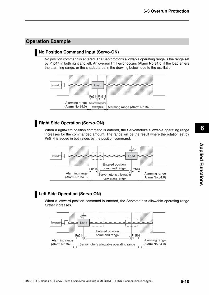
6
6-10
6-3 Overrun Protection
OMNUC G5-Series AC Servo Drives Users Manual (Built-in MECHATROLINK-II communications type)
Ap
plie
d F
un
ctio
ns
Operation Example
No Position Command Input (Servo-ON)
No position command is entered. The Servomotor's allowable operating range is the range set
by Pn514 in both right and left. An overrun limit error occurs (Alarm No.34.0) if the load enters
the alarming range, or the shaded area in the drawing below, due to the oscillation.
Right Side Operation (Servo-ON)
When a rightward position command is entered, the Servomotor's allowable operating range
increases for the commanded amount. The range will be the result where the rotation set by
Pn514 is added in both sides by the position command.
Left Side Operation (Servo-ON)
When a leftward position command is entered, the Servomotor's allowable operating range
further increases.
Servomotor Load
Servomotor's allowable
operating range
Alarming range
(Alarm No.34.0) Alarming range (Alarm No.34.0)
Pn514Pn514
Servomotor Load
Servomotor's allowable
operating range
Entered position
command rangePn514 Pn514
Alarming range
(Alarm No.34.0) Alarming range
(Alarm No.34.0)
Servomotor Load
Servomotor's allowable operating range
Entered position
command range
Alarming range
(Alarm No.34.0)
Alarming range
(Alarm No.34.0)
Pn514 Pn514
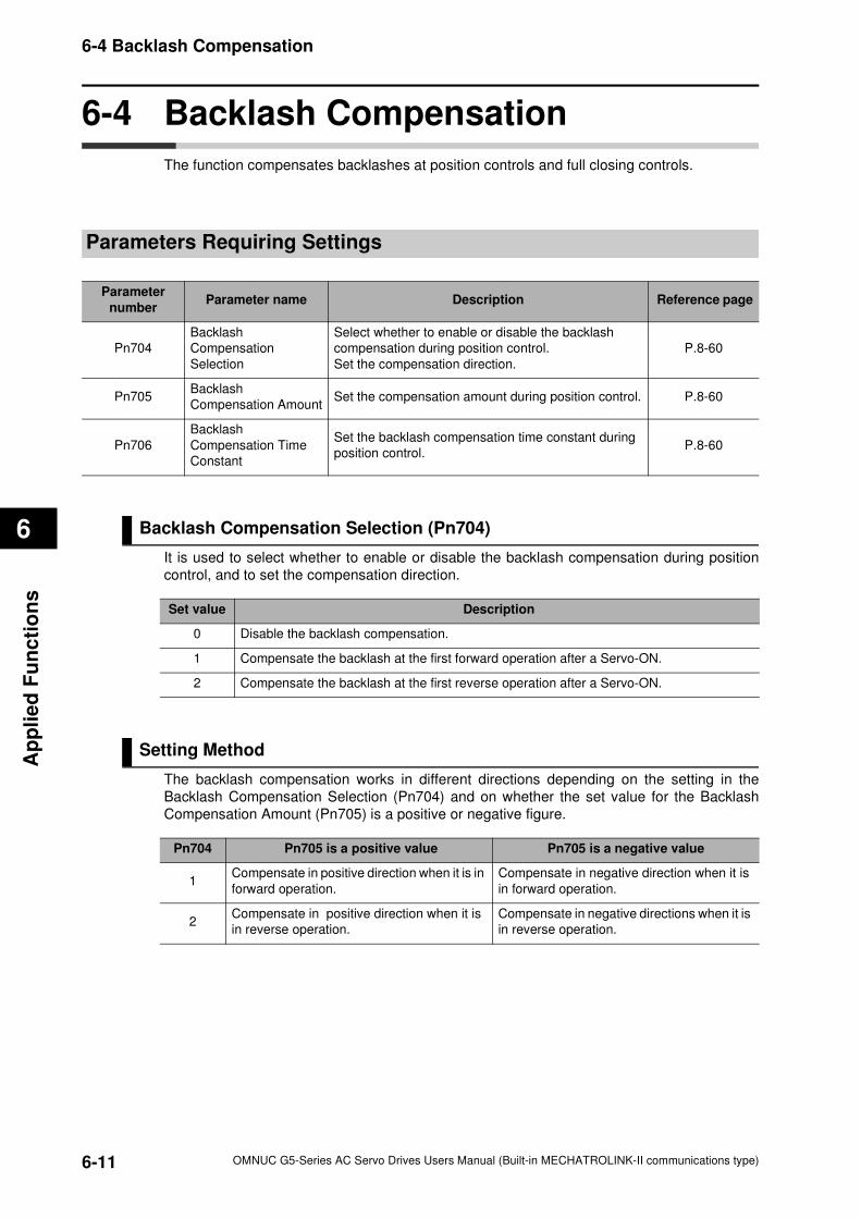
6-11
6-4 Backlash Compensation
OMNUC G5-Series AC Servo Drives Users Manual (Built-in MECHATROLINK-II communications type)
6
Ap
pli
ed
Fu
nc
tio
ns
6-4 Backlash Compensation
The function compensates backlashes at position controls and full closing controls.
Parameters Requiring Settings
Backlash Compensation Selection (Pn704)
It is used to select whether to enable or disable the backlash compensation during position
control, and to set the compensation direction.
Setting Method
The backlash compensation works in different directions depending on the setting in the
Backlash Compensation Selection (Pn704) and on whether the set value for the Backlash
Compensation Amount (Pn705) is a positive or negative figure.
Parameter
numberParameter name Description Reference page
Pn704
Backlash
Compensation
Selection
Select whether to enable or disable the backlash
compensation during position control.
Set the compensation direction.
P.8-60
Pn705Backlash
Compensation AmountSet the compensation amount during position control. P.8-60
Pn706
Backlash
Compensation Time
Constant
Set the backlash compensation time constant during
position control. P.8-60
Set value Description
0 Disable the backlash compensation.
1 Compensate the backlash at the first forward operation after a Servo-ON.
2 Compensate the backlash at the first reverse operation after a Servo-ON.
Pn704 Pn705 is a positive value Pn705 is a negative value
1Compensate in positive direction when it is in
forward operation.
Compensate in negative direction when it is
in forward operation.
2Compensate in positive direction when it is
in reverse operation.
Compensate in negative directions when it is
in reverse operation.
6
6-12
6-4 Backlash Compensation
OMNUC G5-Series AC Servo Drives Users Manual (Built-in MECHATROLINK-II communications type)
Ap
plie
d F
un
ctio
ns
Precautions for Correct Use
The backlash compensation status is retained when you switch from position control to speed
control or to torque control. When you switch back to position control, the backlash compensation
resumes the status retained during the previous position control.
To determine the actual position of the Servomotor, offset the Servomotor position data acquired
via MECHATROLINK-II communications for the backlash compensation amount.
A backlash compensation is performed on the first position command in the set directional
operation after the Servo-ON. Any prior operations in reverse direction are not compensated. But
the first reverse operation after the initial backlash compensation is compensated. A backlash
compensation is not performed twice or more as long as the operation continues in the same
direction.
When the Servo-OFF status occurs while backlash compensation is performed, the backlash
compensation amount is cleared. This is done by presetting the position command data of the
Servo Drive to the Servomotor position data that includes the backlash compensation amount.
When the Servo-ON occurs again, backlash compensation is performed as described above.
Reference
Conditions for Clearing the Backlash Compensation
The backlash compensation is cleared to zero under any of the following conditions: When the position error is reset. This includes the cases of Serve OFF, and when the error counter
is reset by the drive prohibition input.
When the position data is initialized. This excludes the commands of an origin return and a
coordinate system setup, but includes the commends of an equipment setup request and an
adjustment.
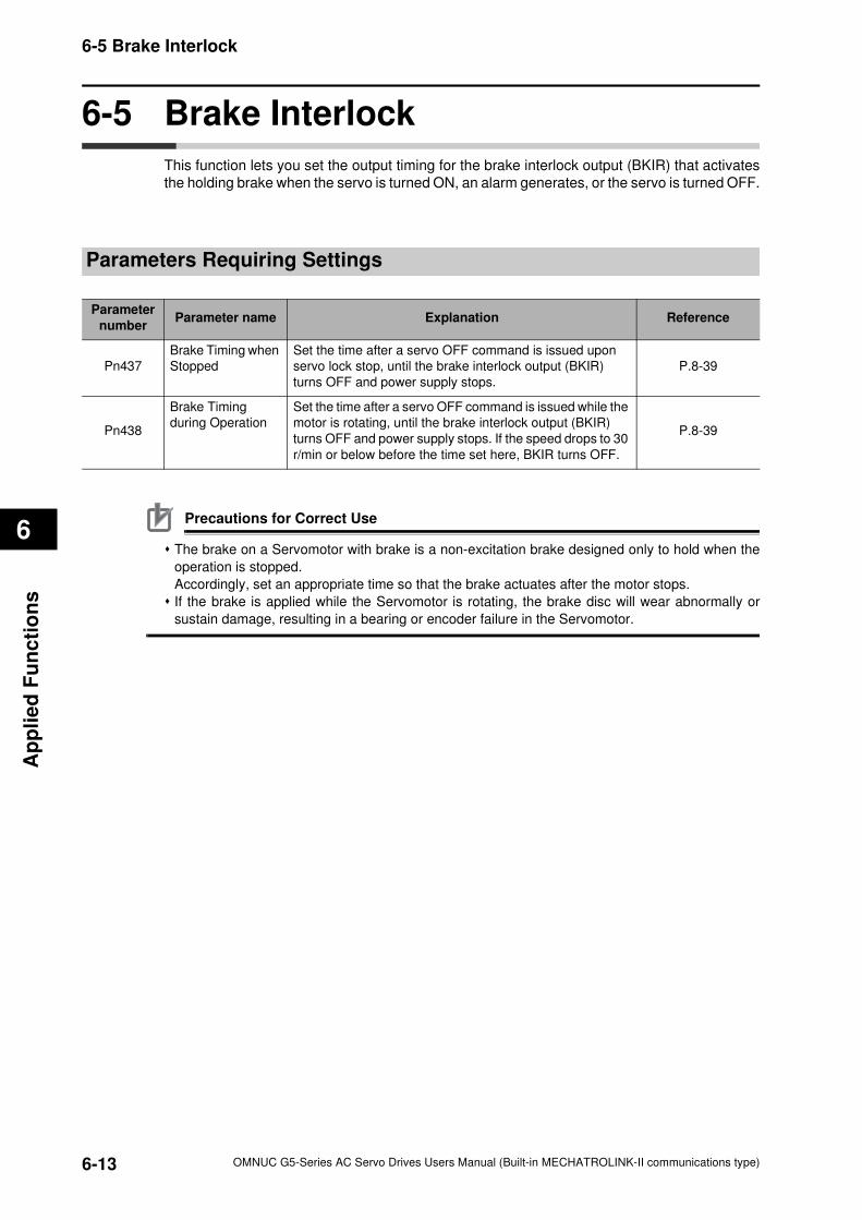
6-13
6-5 Brake Interlock
OMNUC G5-Series AC Servo Drives Users Manual (Built-in MECHATROLINK-II communications type)
6
Ap
pli
ed
Fu
nc
tio
ns
6-5 Brake Interlock
This function lets you set the output timing for the brake interlock output (BKIR) that activates
the holding brake when the servo is turned ON, an alarm generates, or the servo is turned OFF.
Parameters Requiring Settings
Precautions for Correct Use
The brake on a Servomotor with brake is a non-excitation brake designed only to hold when the
operation is stopped.
Accordingly, set an appropriate time so that the brake actuates after the motor stops.
If the brake is applied while the Servomotor is rotating, the brake disc will wear abnormally or
sustain damage, resulting in a bearing or encoder failure in the Servomotor.
Parameter
numberParameter name Explanation Reference
Pn437
Brake Timing when
Stopped
Set the time after a servo OFF command is issued upon
servo lock stop, until the brake interlock output (BKIR)
turns OFF and power supply stops.
P.8-39
Pn438
Brake Timing
during Operation
Set the time after a servo OFF command is issued while the
motor is rotating, until the brake interlock output (BKIR)
turns OFF and power supply stops. If the speed drops to 30
r/min or below before the time set here, BKIR turns OFF.
P.8-39
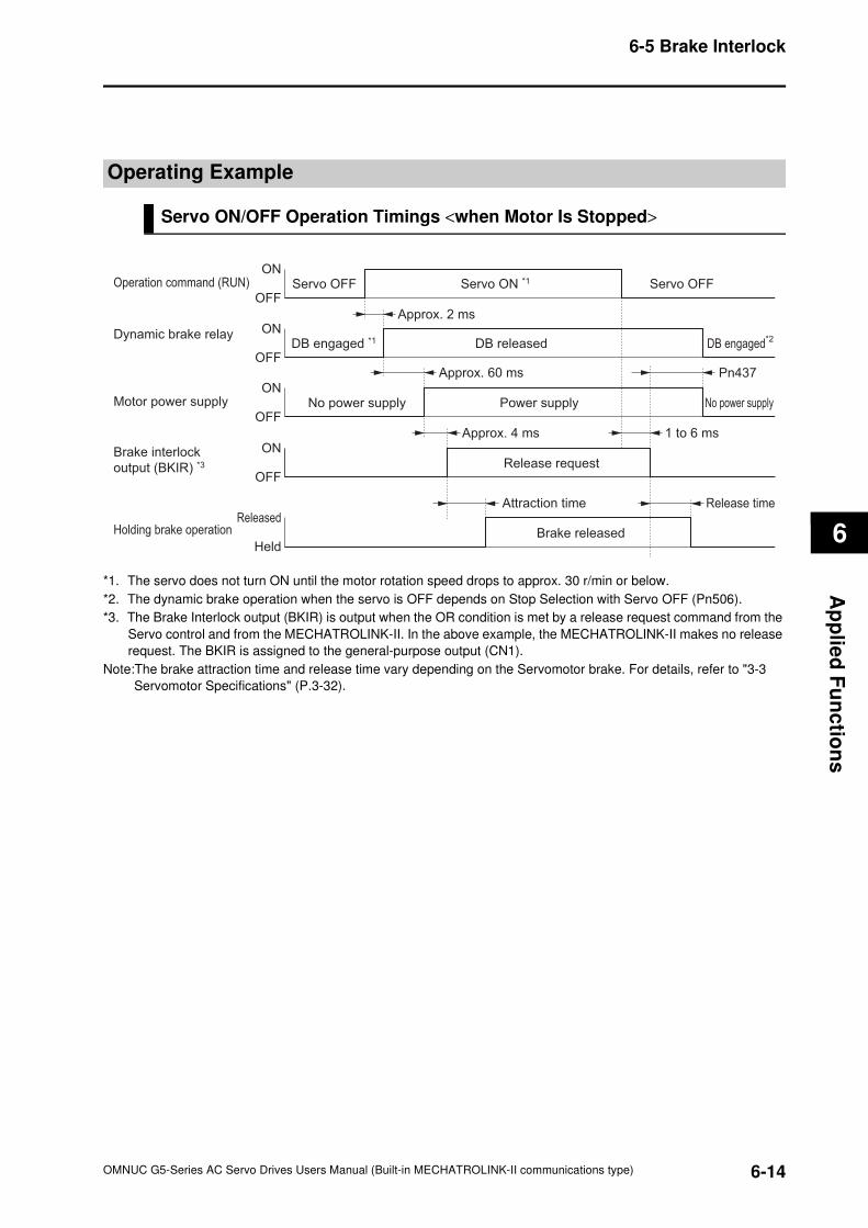
6
6-14
6-5 Brake Interlock
OMNUC G5-Series AC Servo Drives Users Manual (Built-in MECHATROLINK-II communications type)
Ap
plie
d F
un
ctio
ns
Operating Example
Servo ON/OFF Operation Timings <when Motor Is Stopped>
*1. The servo does not turn ON until the motor rotation speed drops to approx. 30 r/min or below.
*2. The dynamic brake operation when the servo is OFF depends on Stop Selection with Servo OFF (Pn506).
*3. The Brake Interlock output (BKIR) is output when the OR condition is met by a release request command from the
Servo control and from the MECHATROLINK-II. In the above example, the MECHATROLINK-II makes no release
request. The BKIR is assigned to the general-purpose output (CN1).
Note:The brake attraction time and release time vary depending on the Servomotor brake. For details, refer to "3-3
Servomotor Specifications" (P.3-32).
Operation command (RUN)ON
OFF
Dynamic brake relay ON
OFF
Motor power supplyON
OFF
ON
OFF
Approx. 2 ms
Approx. 4 ms 1 to 6 ms
Approx. 60 ms
Brake interlock
output (BKIR) *3
Released
Held
Attraction time Release time
Servo OFF Servo OFFServo ON *1
DB engaged *1 DB engaged*2DB released
Power supplyNo power supply No power supply
Pn437
Release request
Holding brake operation Brake released
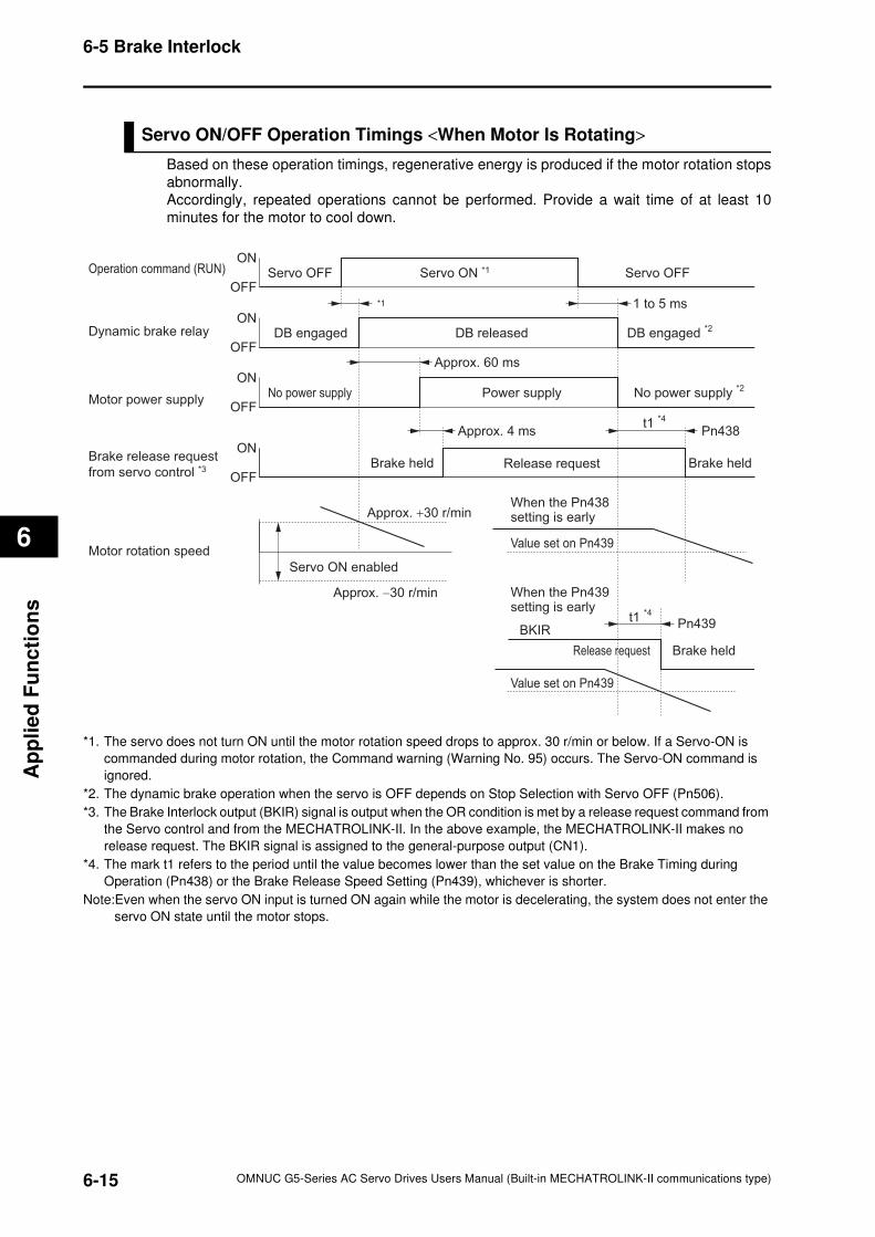
6-15
6-5 Brake Interlock
OMNUC G5-Series AC Servo Drives Users Manual (Built-in MECHATROLINK-II communications type)
6
Ap
pli
ed
Fu
nc
tio
ns
Servo ON/OFF Operation Timings <When Motor Is Rotating>
Based on these operation timings, regenerative energy is produced if the motor rotation stops
abnormally.
Accordingly, repeated operations cannot be performed. Provide a wait time of at least 10
minutes for the motor to cool down.
*1. The servo does not turn ON until the motor rotation speed drops to approx. 30 r/min or below. If a Servo-ON is
commanded during motor rotation, the Command warning (Warning No. 95) occurs. The Servo-ON command is
ignored.
*2. The dynamic brake operation when the servo is OFF depends on Stop Selection with Servo OFF (Pn506).
*3. The Brake Interlock output (BKIR) signal is output when the OR condition is met by a release request command from
the Servo control and from the MECHATROLINK-II. In the above example, the MECHATROLINK-II makes no
release request. The BKIR signal is assigned to the general-purpose output (CN1).
*4. The mark t1 refers to the period until the value becomes lower than the set value on the Brake Timing during
Operation (Pn438) or the Brake Release Speed Setting (Pn439), whichever is shorter.
Note:Even when the servo ON input is turned ON again while the motor is decelerating, the system does not enter the
servo ON state until the motor stops.
Operation command (RUN)ON
OFF
Dynamic brake relayON
OFF
Motor power supply
ON
OFF
Brake release request
from servo control *3
ON
OFF
*1 1 to 5 ms
Approx. 4 ms Pn438
Approx. 60 ms
Servo OFF Servo OFFServo ON *1
DB engaged DB engaged *2DB released
Power supplyNo power supply No power supply *2
Release requestBrake held
t1 *4
Motor rotation speed
Servo ON enabled
Approx. +30 r/min
Value set on Pn439
Approx. −30 r/min
Release request Brake held
Value set on Pn439
BKIR
When the Pn438setting is early
Brake held
t1 *4Pn439
When the Pn439setting is early
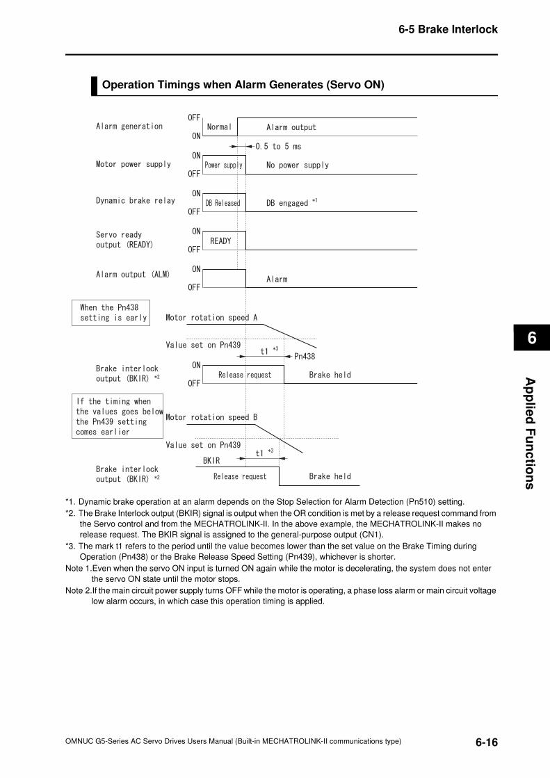
6
6-16
6-5 Brake Interlock
OMNUC G5-Series AC Servo Drives Users Manual (Built-in MECHATROLINK-II communications type)
Ap
plie
d F
un
ctio
ns
Operation Timings when Alarm Generates (Servo ON)
*1. Dynamic brake operation at an alarm depends on the Stop Selection for Alarm Detection (Pn510) setting.
*2. The Brake Interlock output (BKIR) signal is output when the OR condition is met by a release request command from
the Servo control and from the MECHATROLINK-II. In the above example, the MECHATROLINK-II makes no
release request. The BKIR signal is assigned to the general-purpose output (CN1).
*3. The mark t1 refers to the period until the value becomes lower than the set value on the Brake Timing during
Operation (Pn438) or the Brake Release Speed Setting (Pn439), whichever is shorter.
Note 1.Even when the servo ON input is turned ON again while the motor is decelerating, the system does not enter
the servo ON state until the motor stops.
Note 2.If the main circuit power supply turns OFF while the motor is operating, a phase loss alarm or main circuit voltage
low alarm occurs, in which case this operation timing is applied.
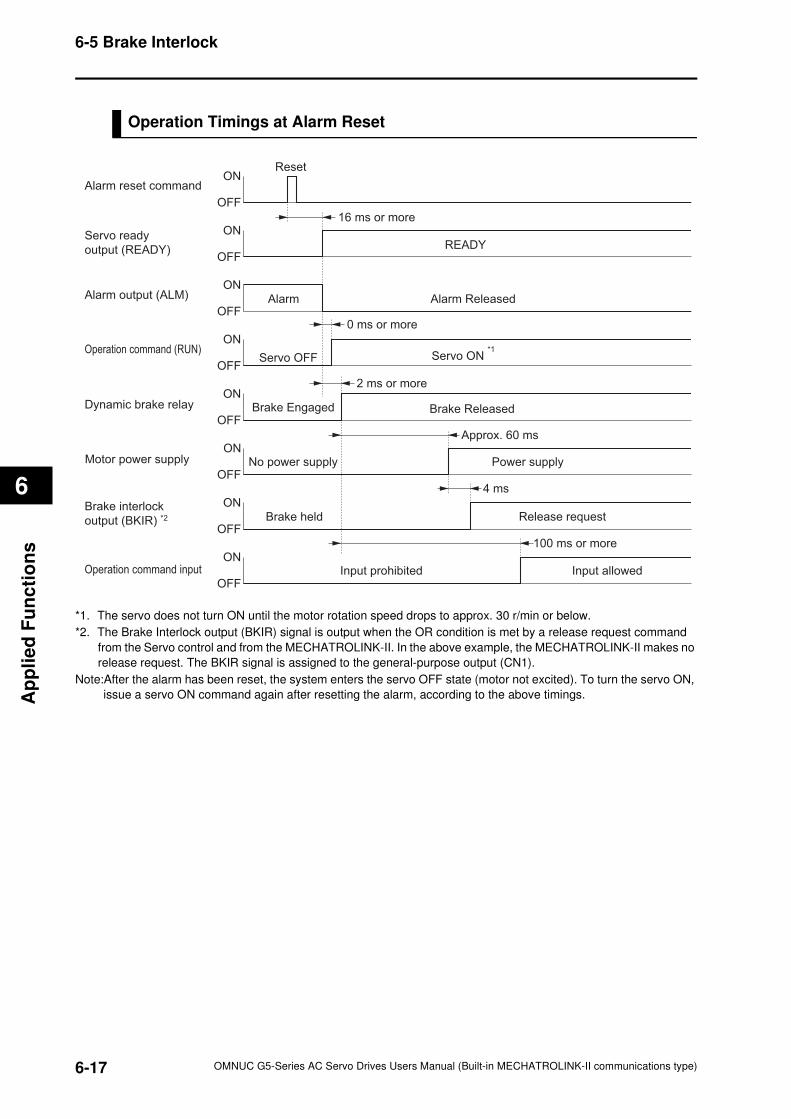
6-17
6-5 Brake Interlock
OMNUC G5-Series AC Servo Drives Users Manual (Built-in MECHATROLINK-II communications type)
6
Ap
pli
ed
Fu
nc
tio
ns
Operation Timings at Alarm Reset
*1. The servo does not turn ON until the motor rotation speed drops to approx. 30 r/min or below.
*2. The Brake Interlock output (BKIR) signal is output when the OR condition is met by a release request command
from the Servo control and from the MECHATROLINK-II. In the above example, the MECHATROLINK-II makes no
release request. The BKIR signal is assigned to the general-purpose output (CN1).
Note:After the alarm has been reset, the system enters the servo OFF state (motor not excited). To turn the servo ON,
issue a servo ON command again after resetting the alarm, according to the above timings.
Alarm reset commandON
OFF
16 ms or more
Alarm output (ALM)
Reset
OFF
ON
OFF
Operation command (RUN)ON
OFF
ON
Brake ReleasedBrake Engaged
READY
ON
OFF
Approx. 60 ms
Brake interlock
output (BKIR) *2
Alarm Alarm Released
OFFPower supply
ON
OFF
ON
OFF
No power supply
Servo ready
output (READY)
Dynamic brake relay
Motor power supplyON
Operation command input
Servo OFF
Input prohibited Input allowed
Servo ON *1
Release requestBrake held
0 ms or more
2 ms or more
4 ms
100 ms or more
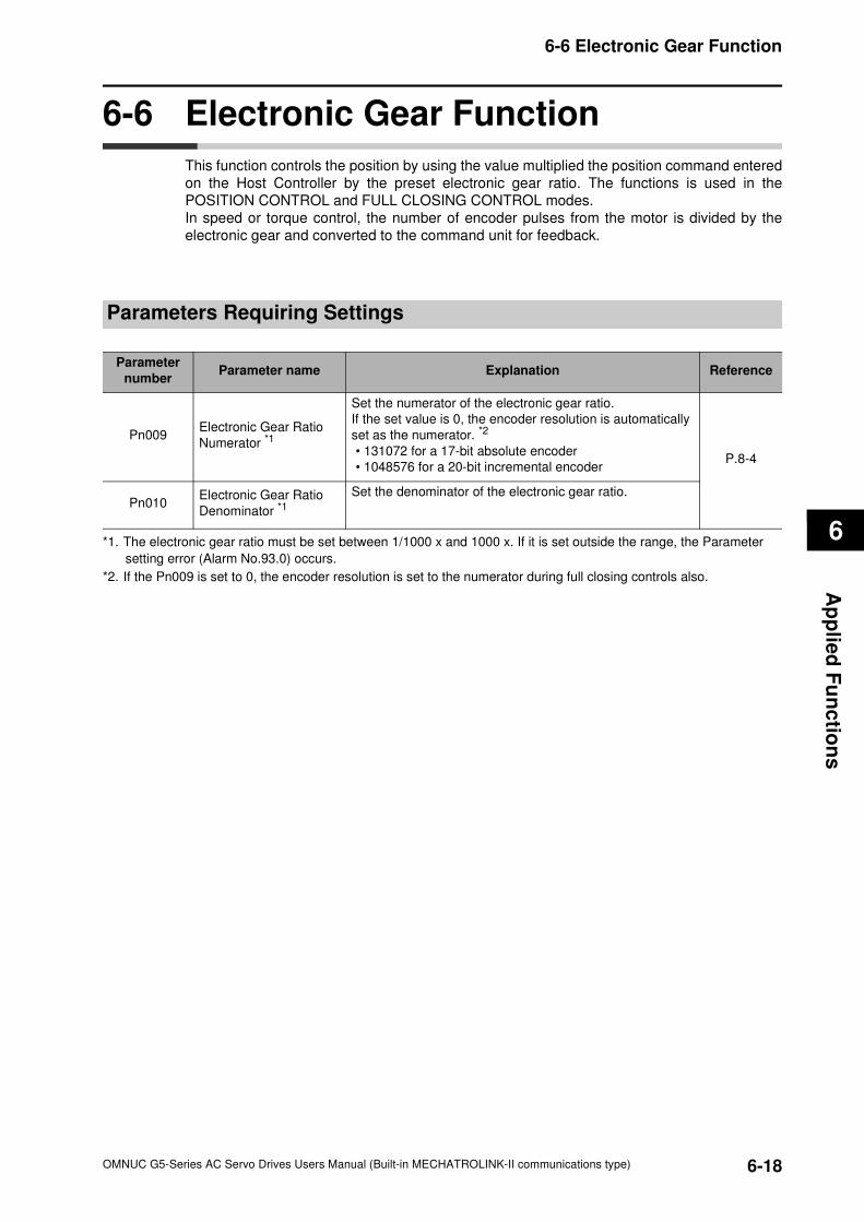
6
6-18
6-6 Electronic Gear Function
OMNUC G5-Series AC Servo Drives Users Manual (Built-in MECHATROLINK-II communications type)
Ap
plie
d F
un
ctio
ns
6-6 Electronic Gear Function
This function controls the position by using the value multiplied the position command entered
on the Host Controller by the preset electronic gear ratio. The functions is used in the
POSITION CONTROL and FULL CLOSING CONTROL modes.
In speed or torque control, the number of encoder pulses from the motor is divided by the
electronic gear and converted to the command unit for feedback.
Parameters Requiring Settings
*1. The electronic gear ratio must be set between 1/1000 x and 1000 x. If it is set outside the range, the Parameter
setting error (Alarm No.93.0) occurs.
*2. If the Pn009 is set to 0, the encoder resolution is set to the numerator during full closing controls also.
Parameter
numberParameter name Explanation Reference
Pn009Electronic Gear Ratio
Numerator *1
Set the numerator of the electronic gear ratio.
If the set value is 0, the encoder resolution is automatically
set as the numerator. *2
• 131072 for a 17-bit absolute encoder
• 1048576 for a 20-bit incremental encoder P.8-4
Pn010Electronic Gear Ratio
Denominator *1Set the denominator of the electronic gear ratio.
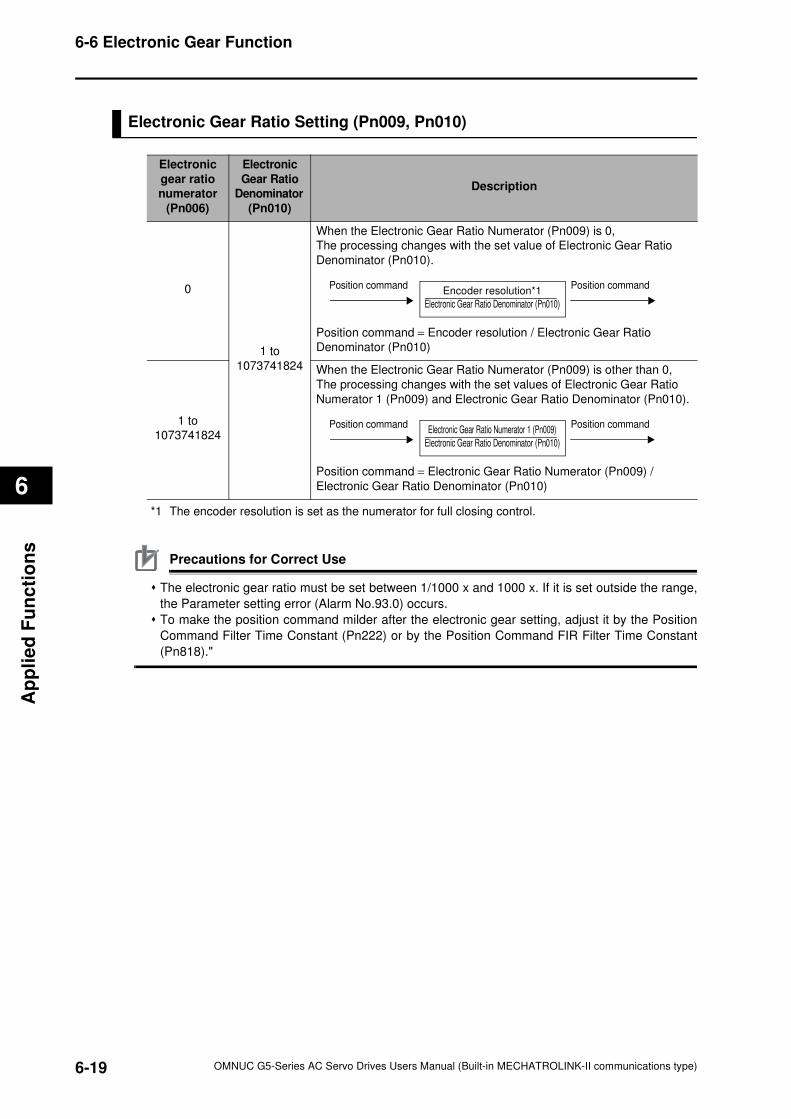
6-19
6-6 Electronic Gear Function
OMNUC G5-Series AC Servo Drives Users Manual (Built-in MECHATROLINK-II communications type)
6
Ap
pli
ed
Fu
nc
tio
ns
Electronic Gear Ratio Setting (Pn009, Pn010)
*1 The encoder resolution is set as the numerator for full closing control.
Precautions for Correct Use
The electronic gear ratio must be set between 1/1000 x and 1000 x. If it is set outside the range,
the Parameter setting error (Alarm No.93.0) occurs.
To make the position command milder after the electronic gear setting, adjust it by the Position
Command Filter Time Constant (Pn222) or by the Position Command FIR Filter Time Constant
(Pn818)."
Electronic
gear ratio
numerator
(Pn006)
Electronic
Gear Ratio
Denominator
(Pn010)
Description
0
1 to
1073741824
When the Electronic Gear Ratio Numerator (Pn009) is 0,
The processing changes with the set value of Electronic Gear Ratio
Denominator (Pn010).
Position command = Encoder resolution / Electronic Gear Ratio
Denominator (Pn010)
1 to
1073741824
When the Electronic Gear Ratio Numerator (Pn009) is other than 0,
The processing changes with the set values of Electronic Gear Ratio
Numerator 1 (Pn009) and Electronic Gear Ratio Denominator (Pn010).
Position command = Electronic Gear Ratio Numerator (Pn009) /
Electronic Gear Ratio Denominator (Pn010)
Position commandEncoder resolution*1
Electronic Gear Ratio Denominator (Pn010)
Position command
Position commandElectronic Gear Ratio Numerator 1 (Pn009)
Electronic Gear Ratio Denominator (Pn010)
Position command
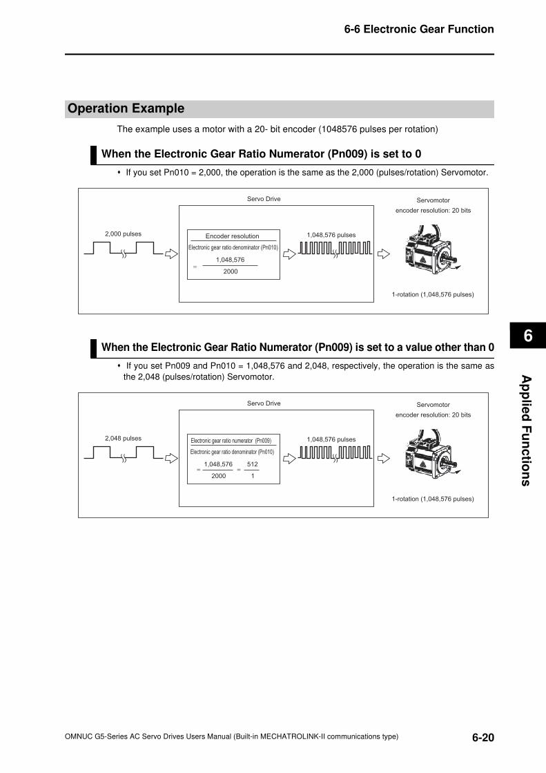
6
6-20
6-6 Electronic Gear Function
OMNUC G5-Series AC Servo Drives Users Manual (Built-in MECHATROLINK-II communications type)
Ap
plie
d F
un
ctio
ns
Operation Example
The example uses a motor with a 20- bit encoder (1048576 pulses per rotation)
When the Electronic Gear Ratio Numerator (Pn009) is set to 0
If you set Pn010 = 2,000, the operation is the same as the 2,000 (pulses/rotation) Servomotor.
When the Electronic Gear Ratio Numerator (Pn009) is set to a value other than 0
If you set Pn009 and Pn010 = 1,048,576 and 2,048, respectively, the operation is the same as
the 2,048 (pulses/rotation) Servomotor.
Encoder resolution
Electronic gear ratio denominator (Pn010)
1,048,576
2000=
Servo Drive
1,048,576 pulses2,000 pulses
Servomotor
encoder resolution: 20 bits
1-rotation (1,048,576 pulses)
Electronic gear ratio numerator (Pn009)
Electronic gear ratio denominator (Pn010)
1,048,576
2000= =
512
1
Servo Drive
1,048,576 pulses2,048 pulses
Servomotor
encoder resolution: 20 bits
1-rotation (1,048,576 pulses)
6-21
6-7 Torque Limit Switching
OMNUC G5-Series AC Servo Drives Users Manual (Built-in MECHATROLINK-II communications type)
6
Ap
pli
ed
Fu
nc
tio
ns
6-7 Torque Limit Switching
The function switches the torque limit by the operation directions, and depending on the
Forward External Torque Limit (PCL), the Reverse External Torque Limit (NCL), and the
Forward/Reverse Torque Limit Input Commands from the MECHATROLINK-II
communications.
This function is used in the following conditions.• When push-motion operation, such as pressing, is performed.
• When the torque at startup and during deceleration should be suppressed to protect the
mechanical system, etc.
The Torque Limit Selection (Pn521) is used to select a method to switch the torque limit.
Operating Conditions
The torque limit switching function works under the following conditions.
Parameters Requiring Settings
Conditions
Operating
Mode *1POSITION CONTROL mode, SPEED CONTROL mode, FULL CLOSING
CONTROL mode
Others
• Servo-ON state
• The factors other than control parameters are set correctly.
This includes the torque limit. The motor operates normally without any failures.
*1.This switching function is disabled in the TORQUE CONTROL mode. Only the No.1 Torque Limit
(Pn013) is effective.
Parameter
numberParameter name Explanation Reference
Pn521 Torque Limit SelectionSelect the torque limit based on the various
parameters and input signals.P.8-49
Pn013 No. 1 Torque Limit Set the No. 1 motor output torque limit value. P.8-5
Pn522 No. 2 Torque Limit Set the No. 2 motor output torque limit value. P.8-50
Pn525Forward External Torque
LimitSet the forward torque limit using a network signal. P.8-50
Pn526Reverse External Torque
LimitSet the reverse torque limit using a network signal. P.8-50
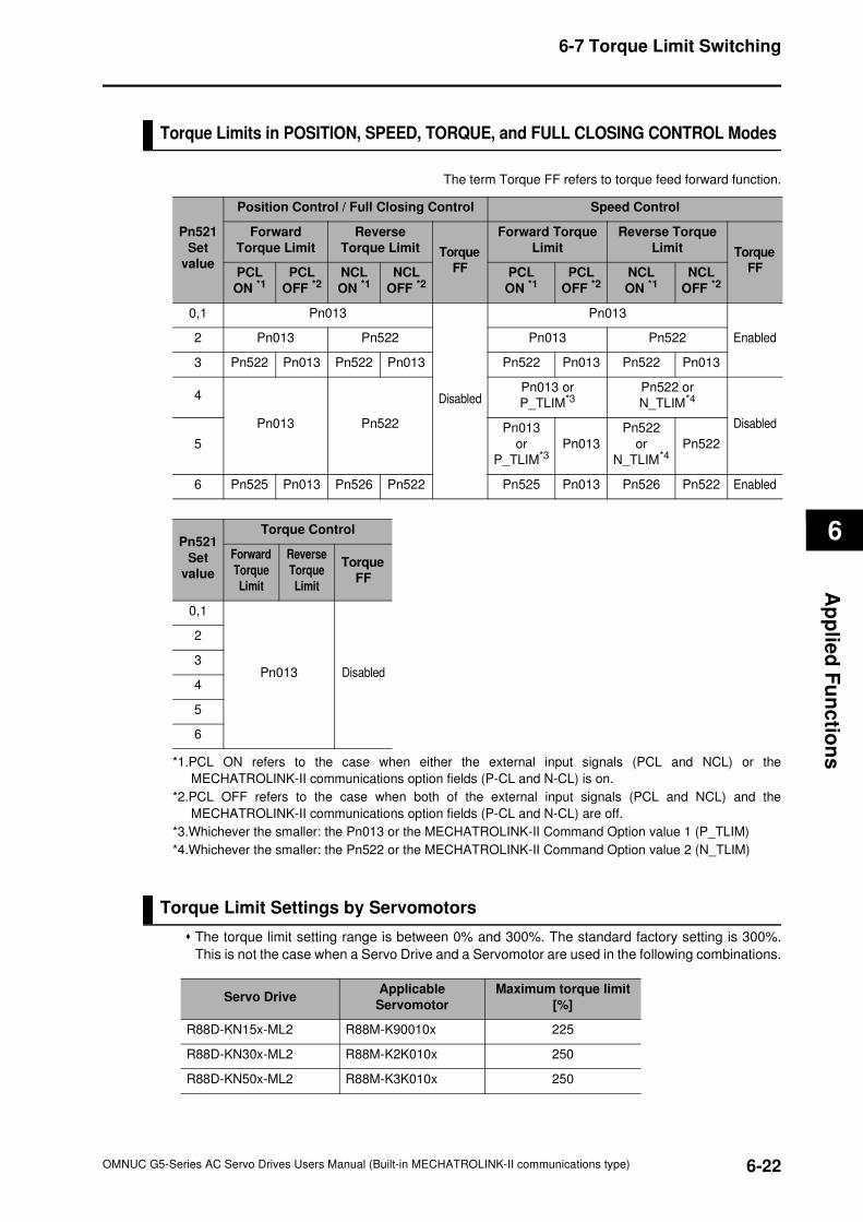
6
6-22
6-7 Torque Limit Switching
OMNUC G5-Series AC Servo Drives Users Manual (Built-in MECHATROLINK-II communications type)
Ap
plie
d F
un
ctio
ns
Torque Limits in POSITION, SPEED, TORQUE, and FULL CLOSING CONTROL Modes
The term Torque FF refers to torque feed forward function.
*1.PCL ON refers to the case when either the external input signals (PCL and NCL) or the
MECHATROLINK-II communications option fields (P-CL and N-CL) is on.
*2.PCL OFF refers to the case when both of the external input signals (PCL and NCL) and the
MECHATROLINK-II communications option fields (P-CL and N-CL) are off.
*3.Whichever the smaller: the Pn013 or the MECHATROLINK-II Command Option value 1 (P_TLIM)
*4.Whichever the smaller: the Pn522 or the MECHATROLINK-II Command Option value 2 (N_TLIM)
Torque Limit Settings by Servomotors
The torque limit setting range is between 0% and 300%. The standard factory setting is 300%.
This is not the case when a Servo Drive and a Servomotor are used in the following combinations.
Pn521
Set
value
Position Control / Full Closing Control Speed Control
Forward
Torque Limit
Reverse
Torque Limit Torque
FF
Forward Torque
Limit
Reverse Torque
Limit Torque
FFPCL
ON *1PCL
OFF *2NCL
ON *1NCL
OFF *2PCL
ON *1PCL
OFF *2NCL
ON *1NCL
OFF *2
0,1 Pn013
Disabled
Pn013
Enabled2 Pn013 Pn522 Pn013 Pn522
3 Pn522 Pn013 Pn522 Pn013 Pn522 Pn013 Pn522 Pn013
4
Pn013 Pn522
Pn013 or
P_TLIM*3Pn522 or
N_TLIM*4
Disabled
5
Pn013
or
P_TLIM*3Pn013
Pn522
or
N_TLIM*4Pn522
6 Pn525 Pn013 Pn526 Pn522 Pn525 Pn013 Pn526 Pn522 Enabled
Pn521
Set
value
Torque Control
Forward
Torque
Limit
Reverse
Torque
Limit
Torque
FF
0,1
Pn013 Disabled
2
3
4
5
6
Servo DriveApplicable
Servomotor
Maximum torque limit
[%]
R88D-KN15x-ML2 R88M-K90010x 225
R88D-KN30x-ML2 R88M-K2K010x 250
R88D-KN50x-ML2 R88M-K3K010x 250
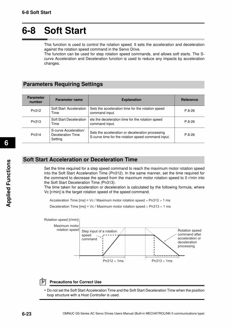
6-23
6-8 Soft Start
OMNUC G5-Series AC Servo Drives Users Manual (Built-in MECHATROLINK-II communications type)
6
Ap
pli
ed
Fu
nc
tio
ns
6-8 Soft Start
This function is used to control the rotation speed. It sets the acceleration and deceleration
against the rotation speed command in the Servo Drive.
The function can be used for step rotation speed commands, and allows soft starts. The S-
curve Acceleration and Deceleration function is used to reduce any impacts by acceleration
changes.
Parameters Requiring Settings
Soft Start Acceleration or Deceleration Time
Set the time required for a step speed command to reach the maximum motor rotation speed
into the Soft Start Acceleration Time (Pn312). In the same manner, set the time required for
the command to decrease the speed from the maximum motor rotation speed to 0 r/min into
the Soft Start Deceleration Time (Pn313).
The time taken for acceleration or deceleration is calculated by the following formula, where
Vc [r/min] is the target rotation speed of the speed command.
Precautions for Correct Use
Do not set the Soft Start Acceleration Time and the Soft Start Deceleration Time when the position
loop structure with a Host Controller is used.
Parameter
numberParameter name Explanation Reference
Pn312Soft Start Acceleration
Time
Sets the acceleration time for the rotation speed
command input.P.8-26
Pn313Soft Start Deceleration
Time
ets the deceleration time for the rotation speed
command input.P.8-26
Pn314
S-curve Acceleration/
Deceleration Time
Setting
Sets the acceleration or deceleration processing
S-curve time for the rotation speed command input.P.8-26
Acceleration Time [ms] = Vc / Maximum motor rotation speed × Pn312 × 1 ms
Deceleration Time [ms] = Vc / Maximum motor rotation speed × Pn313 × 1 ms
Rotation speed [r/min]
Maximum motorrotation speed Step input of a rotation
speed command
Rotation speed command after acceleration or deceleration processing
Pn312 × 1ms Pn313 × 1ms
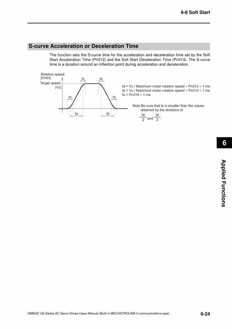
6
6-24
6-8 Soft Start
OMNUC G5-Series AC Servo Drives Users Manual (Built-in MECHATROLINK-II communications type)
Ap
plie
d F
un
ctio
ns
S-curve Acceleration or Deceleration Time
The function sets the S-curve time for the acceleration and deceleration time set by the Soft
Start Acceleration Time (Pn312) and the Soft Start Deceleration Time (Pn313). The S-curve
time is a duration around an inflection point during acceleration and deceleration.
ta td
ts ts
tsts
Rotation speed [r/min]
Target speed
(Vc) ta = Vc / Maximum motor rotation speed × Pn312 × 1 ms
td = Vc / Maximum motor rotation speed × Pn313 × 1 ms
ts = Pn314 × 1 ms
Note Be sure that ts is smaller than the values
obtained by the divisions of
and .2
ta
2
td
6-25
6-9 Gain Switching Function
OMNUC G5-Series AC Servo Drives Users Manual (Built-in MECHATROLINK-II communications type)
6
Ap
pli
ed
Fu
nc
tio
ns
6-9 Gain Switching Function
This function switches the position loop and speed loop gain.
Select enable or disable using GAIN SWITCHING INPUT OPERATING mode Selection
(Pn114). Set the switching condition using gain switching setting.
If the load inertia changes or you want to change the responsiveness depending on whether
the motor is stopping and operating, you can perform an optimal control by gain switching.
The function is used when the realtime autotuning does not work effectively, such as:• When the load inertia fluctuates in 200 ms or less.
• When the motor rotation speed does not exceed 500 r/min, or load torque does not exceed
50% of the rated torque.
• When external force is constantly applied, as with a vertical axis.
Precautions for Correct Use
When the gain 2 has been selected, realtime autotuning does not operate normally. If using the
gain switching, set the Realtime Autotuning to "Disabled" (Pn002 = 0).
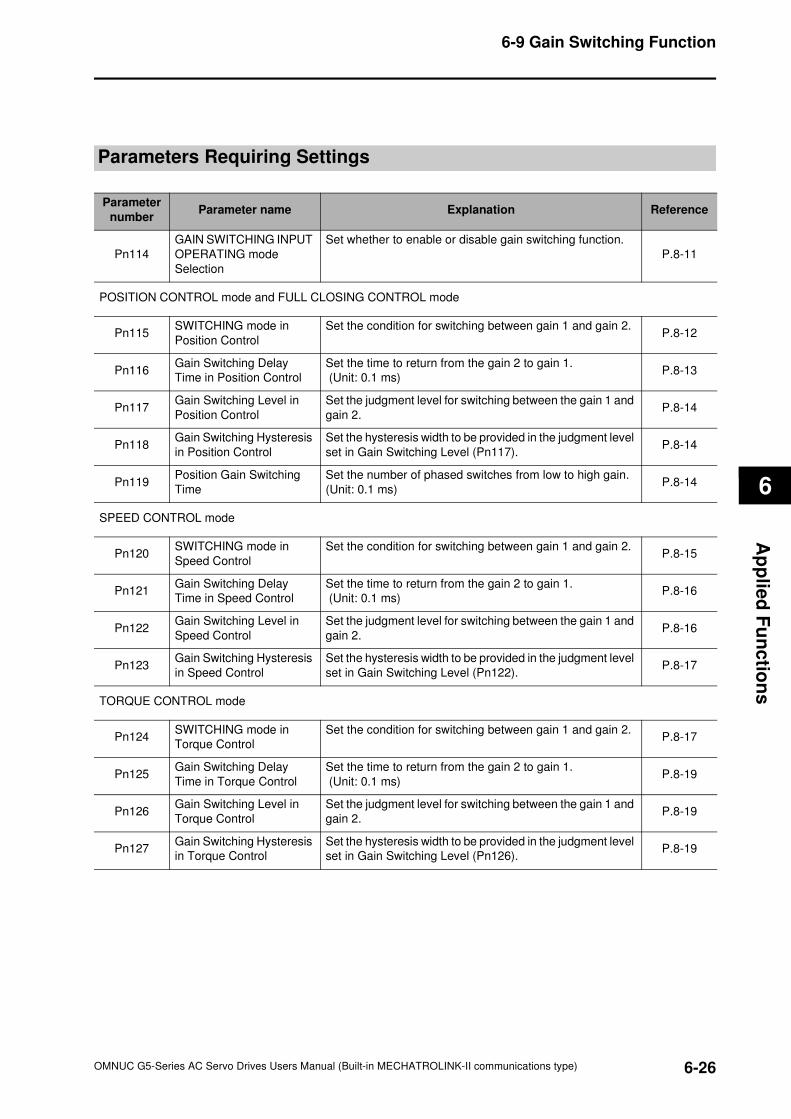
6
6-26
6-9 Gain Switching Function
OMNUC G5-Series AC Servo Drives Users Manual (Built-in MECHATROLINK-II communications type)
Ap
plie
d F
un
ctio
ns
Parameters Requiring Settings
Parameter
numberParameter name Explanation Reference
Pn114
GAIN SWITCHING INPUT
OPERATING mode
Selection
Set whether to enable or disable gain switching function.
P.8-11
POSITION CONTROL mode and FULL CLOSING CONTROL mode
Pn115SWITCHING mode in
Position Control
Set the condition for switching between gain 1 and gain 2.P.8-12
Pn116Gain Switching Delay
Time in Position Control
Set the time to return from the gain 2 to gain 1.
(Unit: 0.1 ms)P.8-13
Pn117Gain Switching Level in
Position Control
Set the judgment level for switching between the gain 1 and
gain 2.P.8-14
Pn118Gain Switching Hysteresis
in Position Control
Set the hysteresis width to be provided in the judgment level
set in Gain Switching Level (Pn117).P.8-14
Pn119Position Gain Switching
Time
Set the number of phased switches from low to high gain.
(Unit: 0.1 ms)P.8-14
SPEED CONTROL mode
Pn120SWITCHING mode in
Speed Control
Set the condition for switching between gain 1 and gain 2.P.8-15
Pn121Gain Switching Delay
Time in Speed Control
Set the time to return from the gain 2 to gain 1.
(Unit: 0.1 ms)P.8-16
Pn122Gain Switching Level in
Speed Control
Set the judgment level for switching between the gain 1 and
gain 2.P.8-16
Pn123Gain Switching Hysteresis
in Speed Control
Set the hysteresis width to be provided in the judgment level
set in Gain Switching Level (Pn122).P.8-17
TORQUE CONTROL mode
Pn124SWITCHING mode in
Torque Control
Set the condition for switching between gain 1 and gain 2.P.8-17
Pn125Gain Switching Delay
Time in Torque Control
Set the time to return from the gain 2 to gain 1.
(Unit: 0.1 ms)P.8-19
Pn126Gain Switching Level in
Torque Control
Set the judgment level for switching between the gain 1 and
gain 2.P.8-19
Pn127Gain Switching Hysteresis
in Torque Control
Set the hysteresis width to be provided in the judgment level
set in Gain Switching Level (Pn126).P.8-19
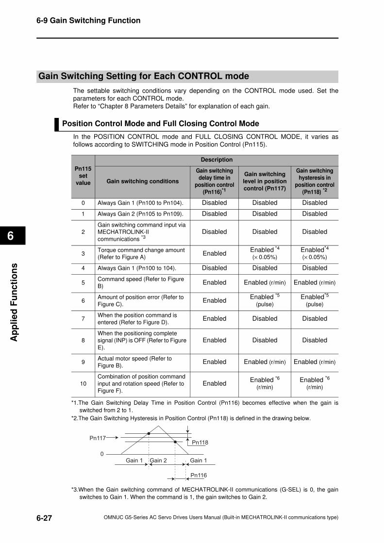
6-27
6-9 Gain Switching Function
OMNUC G5-Series AC Servo Drives Users Manual (Built-in MECHATROLINK-II communications type)
6
Ap
pli
ed
Fu
nc
tio
ns
Gain Switching Setting for Each CONTROL mode
The settable switching conditions vary depending on the CONTROL mode used. Set the
parameters for each CONTROL mode.
Refer to “Chapter 8 Parameters Details” for explanation of each gain.
Position Control Mode and Full Closing Control Mode
In the POSITION CONTROL mode and FULL CLOSING CONTROL MODE, it varies as
follows according to SWITCHING mode in Position Control (Pn115).
Pn115
set
value
Description
Gain switching conditions
Gain switching
delay time in
position control
(Pn116)*1
Gain switching
level in position
control (Pn117)
Gain switching
hysteresis in
position control
(Pn118) *2
0 Always Gain 1 (Pn100 to Pn104). Disabled Disabled Disabled
1 Always Gain 2 (Pn105 to Pn109). Disabled Disabled Disabled
2
Gain switching command input via
MECHATROLINK-II
communications *3Disabled Disabled Disabled
3Torque command change amount
(Refer to Figure A)Enabled
Enabled *4
(× 0.05%)
Enabled*4
(× 0.05%)
4 Always Gain 1 (Pn100 to 104). Disabled Disabled Disabled
5Command speed (Refer to Figure
B)Enabled Enabled (r/min) Enabled (r/min)
6Amount of position error (Refer to
Figure C).Enabled
Enabled *5
(pulse)
Enabled*5
(pulse)
7When the position command is
entered (Refer to Figure D).Enabled Disabled Disabled
8
When the positioning complete
signal (INP) is OFF (Refer to Figure
E).
Enabled Disabled Disabled
9Actual motor speed (Refer to
Figure B).Enabled Enabled (r/min) Enabled (r/min)
10
Combination of position command
input and rotation speed (Refer to
Figure F).
EnabledEnabled *6
(r/min)
Enabled *6
(r/min)
*1.The Gain Switching Delay Time in Position Control (Pn116) becomes effective when the gain is
switched from 2 to 1.
*2.The Gain Switching Hysteresis in Position Control (Pn118) is defined in the drawing below.
*3.When the Gain switching command of MECHATROLINK-II communications (G-SEL) is 0, the gain
switches to Gain 1. When the command is 1, the gain switches to Gain 2.
Pn117
0
Pn118
Pn116
Gain 1 Gain 2 Gain 1
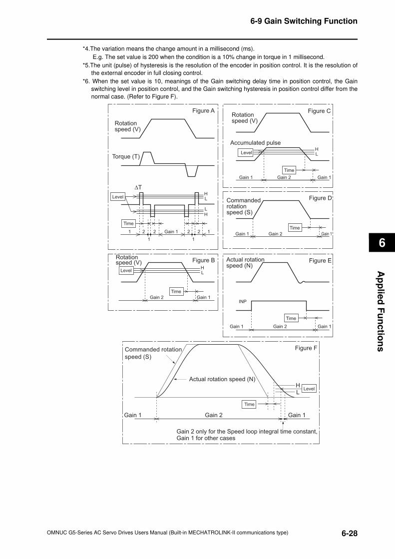
6
6-28
6-9 Gain Switching Function
OMNUC G5-Series AC Servo Drives Users Manual (Built-in MECHATROLINK-II communications type)
Ap
plie
d F
un
ctio
ns
*4.The variation means the change amount in a millisecond (ms).
E.g. The set value is 200 when the condition is a 10% change in torque in 1 millisecond.
*5.The unit (pulse) of hysteresis is the resolution of the encoder in position control. It is the resolution of
the external encoder in full closing control.
*6. When the set value is 10, meanings of the Gain switching delay time in position control, the Gain
switching level in position control, and the Gain switching hysteresis in position control differ from the
normal case. (Refer to Figure F).
HL
HL
HL
HL
Figure A
Rotation speed (V)
Torque (T)
∆T
Time
1
1
2 2 2 2
1
1Gain 1
Figure CRotation speed (V)
Gain 1 Gain 1Gain 2
Accumulated pulse
Level
Time
Figure DCommanded rotation speed (S)
Gain 1 Gain 1Gain 2
Time
Figure EActual rotation speed (N)
INP
Gain 1 Gain 1Gain 2
Time
Figure BRotation speed (V)
Gain 1Gain 2
Time
Commanded rotation
speed (S)
Gain 1 Gain 2
Actual rotation speed (N)
Time
HL
Gain 1
Gain 2 only for the Speed loop integral time constant, Gain 1 for other cases
Figure F
Level
Level
Level
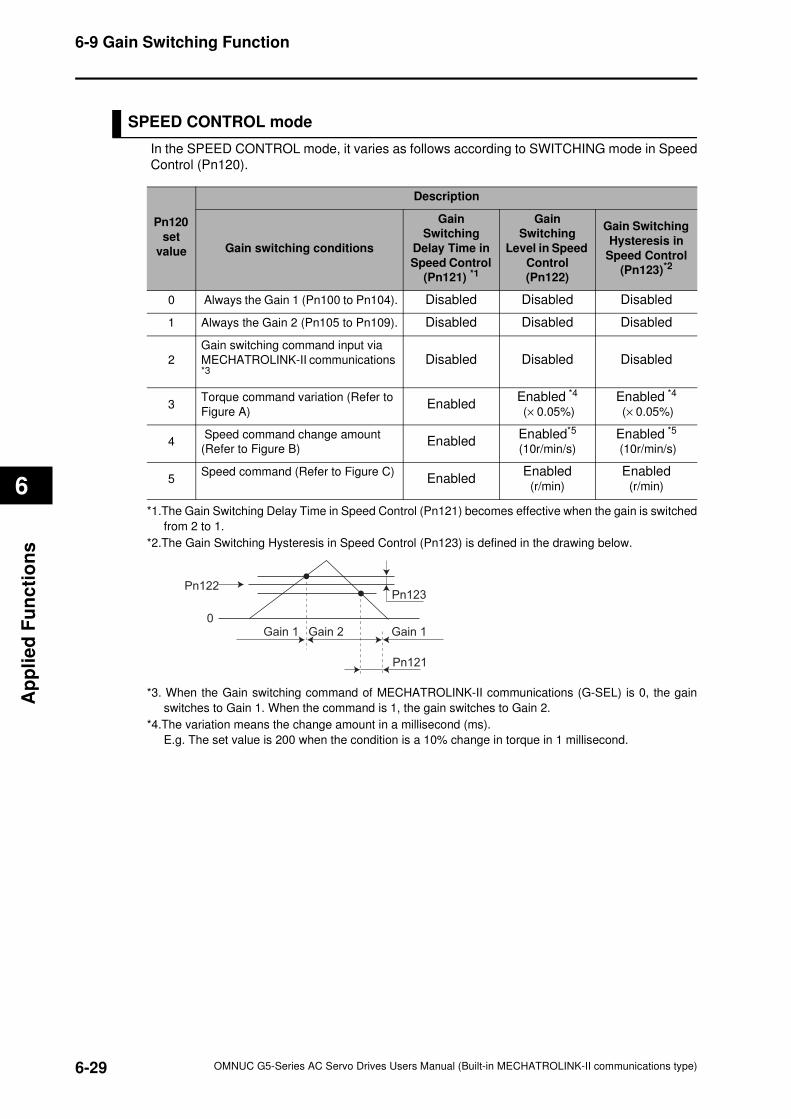
6-29
6-9 Gain Switching Function
OMNUC G5-Series AC Servo Drives Users Manual (Built-in MECHATROLINK-II communications type)
6
Ap
pli
ed
Fu
nc
tio
ns
SPEED CONTROL mode
In the SPEED CONTROL mode, it varies as follows according to SWITCHING mode in Speed
Control (Pn120).
Pn120
set
value
Description
Gain switching conditions
Gain
Switching
Delay Time in
Speed Control
(Pn121) *1
Gain
Switching
Level in Speed
Control
(Pn122)
Gain Switching
Hysteresis in
Speed Control
(Pn123)*2
0 Always the Gain 1 (Pn100 to Pn104). Disabled Disabled Disabled
1 Always the Gain 2 (Pn105 to Pn109). Disabled Disabled Disabled
2
Gain switching command input via
MECHATROLINK-II communications *3
Disabled Disabled Disabled
3Torque command variation (Refer to
Figure A)Enabled
Enabled *4
(× 0.05%)
Enabled *4
(× 0.05%)
4 Speed command change amount
(Refer to Figure B)Enabled
Enabled*5
(10r/min/s)
Enabled *5
(10r/min/s)
5Speed command (Refer to Figure C)
EnabledEnabled
(r/min)
Enabled
(r/min)
*1.The Gain Switching Delay Time in Speed Control (Pn121) becomes effective when the gain is switched
from 2 to 1.
*2.The Gain Switching Hysteresis in Speed Control (Pn123) is defined in the drawing below.
*3. When the Gain switching command of MECHATROLINK-II communications (G-SEL) is 0, the gain
switches to Gain 1. When the command is 1, the gain switches to Gain 2.
*4.The variation means the change amount in a millisecond (ms).
E.g. The set value is 200 when the condition is a 10% change in torque in 1 millisecond.
Pn122
0
Pn123
Pn121
Gain 1 Gain 2 Gain 1
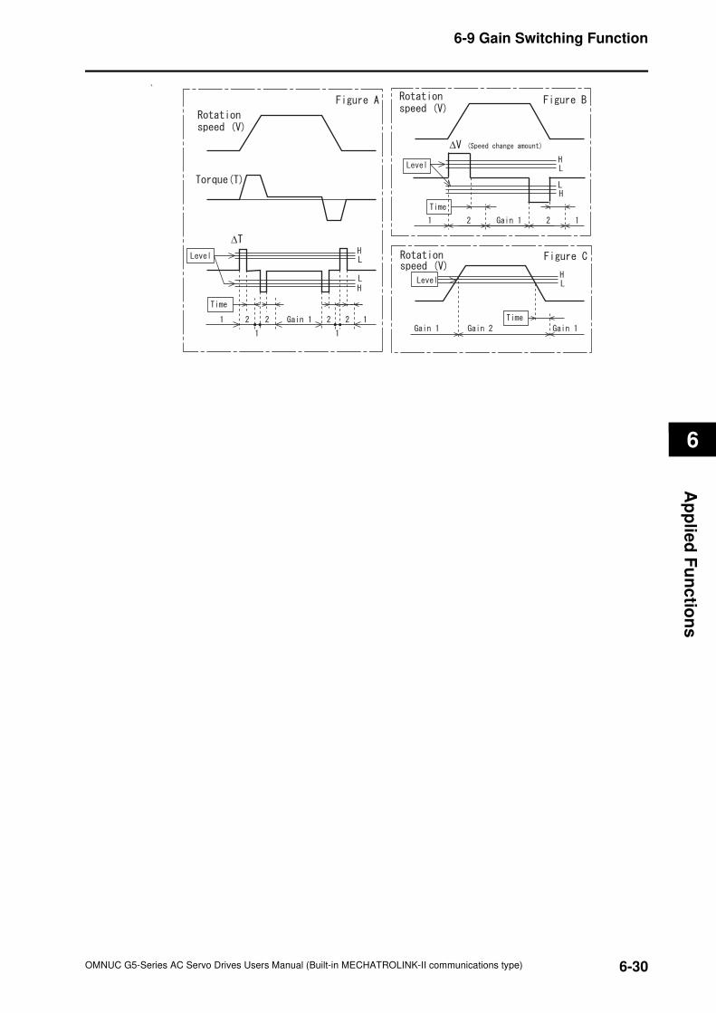
6
6-30
6-9 Gain Switching Function
OMNUC G5-Series AC Servo Drives Users Manual (Built-in MECHATROLINK-II communications type)
Ap
plie
d F
un
ctio
ns
*5.
∆
∆
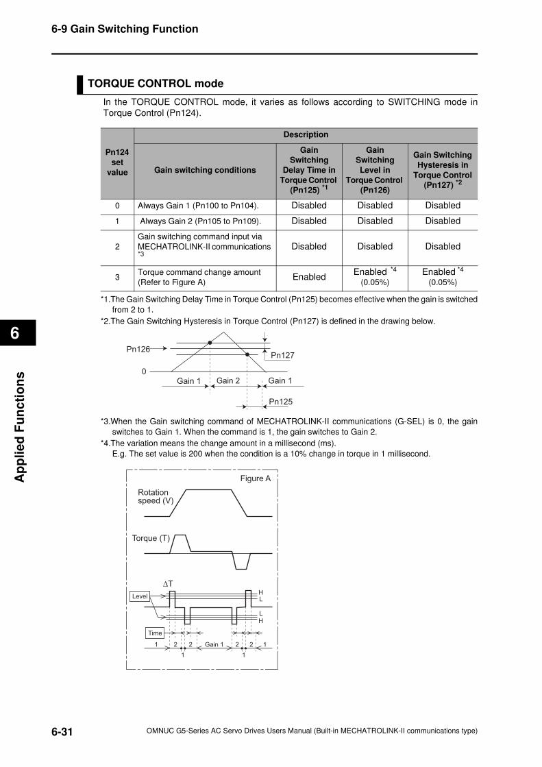
6-31
6-9 Gain Switching Function
OMNUC G5-Series AC Servo Drives Users Manual (Built-in MECHATROLINK-II communications type)
6
Ap
pli
ed
Fu
nc
tio
ns
TORQUE CONTROL mode
In the TORQUE CONTROL mode, it varies as follows according to SWITCHING mode in
Torque Control (Pn124).
Pn124
set
value
Description
Gain switching conditions
Gain
Switching
Delay Time in
Torque Control
(Pn125) *1
Gain
Switching
Level in
Torque Control
(Pn126)
Gain Switching
Hysteresis in
Torque Control
(Pn127) *2
0 Always Gain 1 (Pn100 to Pn104). Disabled Disabled Disabled
1 Always Gain 2 (Pn105 to Pn109). Disabled Disabled Disabled
2
Gain switching command input via
MECHATROLINK-II communications *3
Disabled Disabled Disabled
3Torque command change amount
(Refer to Figure A)Enabled
Enabled *4
(0.05%)
Enabled *4
(0.05%)
*1.The Gain Switching Delay Time in Torque Control (Pn125) becomes effective when the gain is switched
from 2 to 1.
*2.The Gain Switching Hysteresis in Torque Control (Pn127) is defined in the drawing below.
*3.When the Gain switching command of MECHATROLINK-II communications (G-SEL) is 0, the gain
switches to Gain 1. When the command is 1, the gain switches to Gain 2.
*4.The variation means the change amount in a millisecond (ms).
E.g. The set value is 200 when the condition is a 10% change in torque in 1 millisecond.
Pn126
0
Pn127
Pn125
Gain 1 Gain 2 Gain 1
HL
HL
Figure A
Rotation speed (V)
Torque (T)
∆T
Time
1
1
2 2 2 2
1
1Gain 1
Level
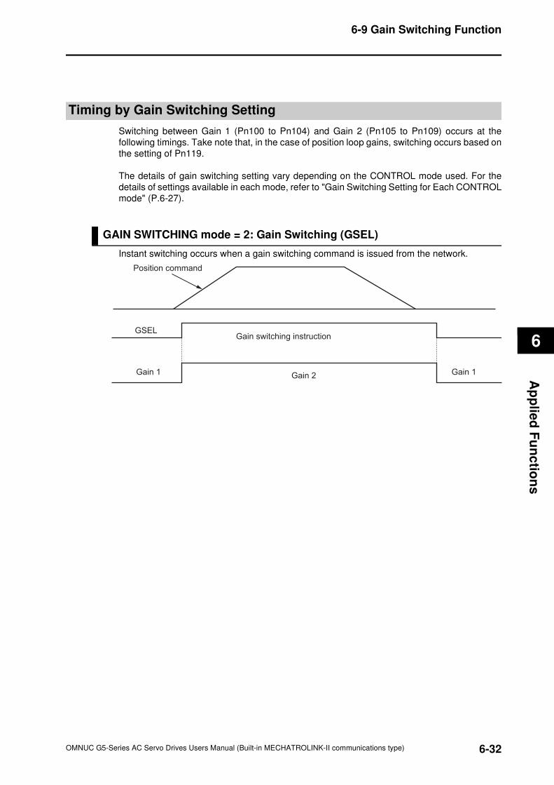
6
6-32
6-9 Gain Switching Function
OMNUC G5-Series AC Servo Drives Users Manual (Built-in MECHATROLINK-II communications type)
Ap
plie
d F
un
ctio
ns
Timing by Gain Switching Setting
Switching between Gain 1 (Pn100 to Pn104) and Gain 2 (Pn105 to Pn109) occurs at the
following timings. Take note that, in the case of position loop gains, switching occurs based on
the setting of Pn119.
The details of gain switching setting vary depending on the CONTROL mode used. For the
details of settings available in each mode, refer to "Gain Switching Setting for Each CONTROL
mode" (P.6-27).
GAIN SWITCHING mode = 2: Gain Switching (GSEL)
Instant switching occurs when a gain switching command is issued from the network.
Gain 1
GSEL
Gain 1Gain 2
Gain switching instruction
Position command
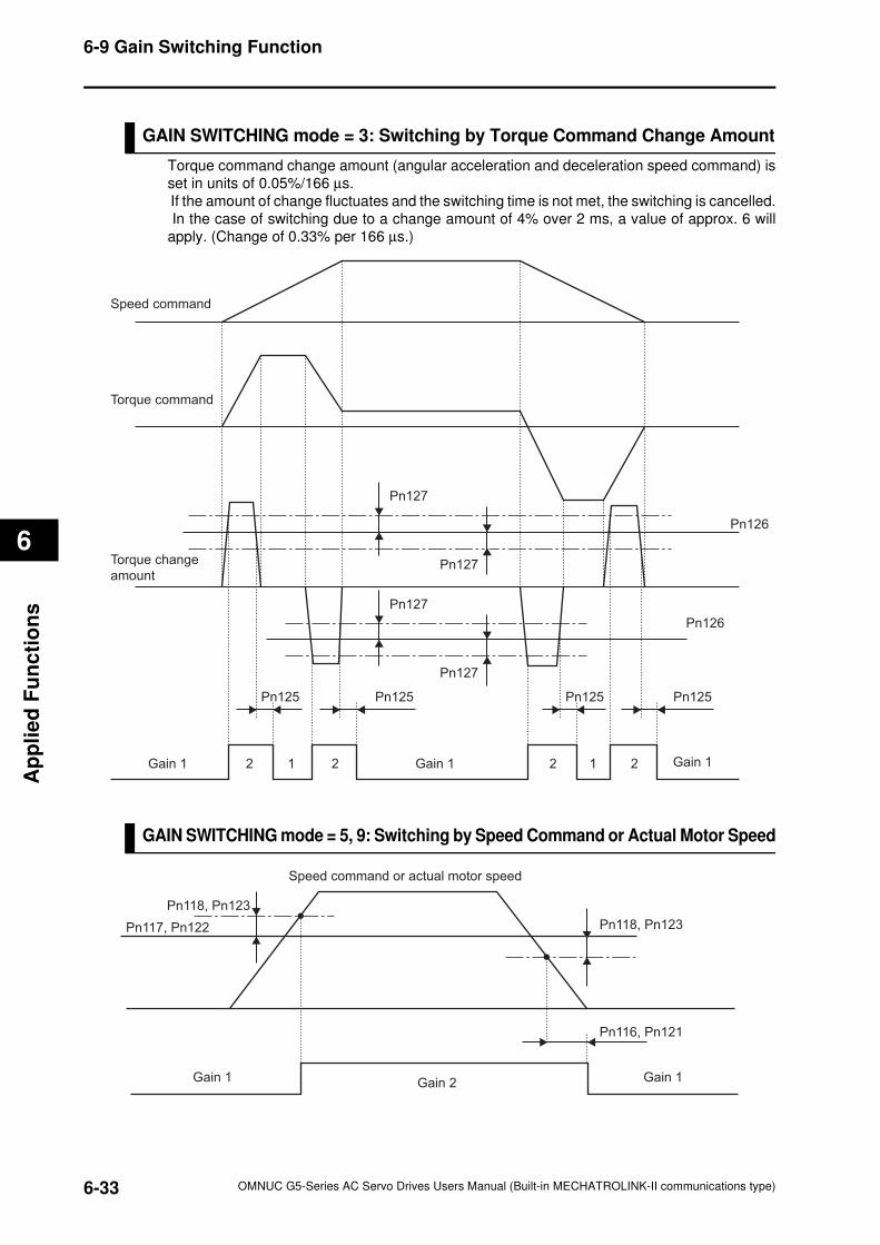
6-33
6-9 Gain Switching Function
OMNUC G5-Series AC Servo Drives Users Manual (Built-in MECHATROLINK-II communications type)
6
Ap
pli
ed
Fu
nc
tio
ns
GAIN SWITCHING mode = 3: Switching by Torque Command Change Amount
Torque command change amount (angular acceleration and deceleration speed command) is
set in units of 0.05%/166 µs.
If the amount of change fluctuates and the switching time is not met, the switching is cancelled.
In the case of switching due to a change amount of 4% over 2 ms, a value of approx. 6 will
apply. (Change of 0.33% per 166 µs.)
GAIN SWITCHING mode = 5, 9: Switching by Speed Command or Actual Motor Speed
Gain 1 Gain 11 12 2 22 Gain 1
Pn125Pn125
Pn127
Pn127
Pn126
Pn126
Pn127
Pn127
Pn125 Pn125
Speed command
Torque command
Torque change
amount
Gain 1 Gain 1Gain 2
Speed command or actual motor speed
Pn118, Pn123
Pn117, Pn122 Pn118, Pn123
Pn116, Pn121
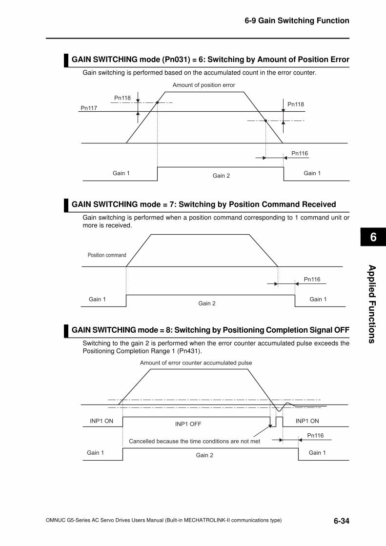
6
6-34
6-9 Gain Switching Function
OMNUC G5-Series AC Servo Drives Users Manual (Built-in MECHATROLINK-II communications type)
Ap
plie
d F
un
ctio
ns
GAIN SWITCHING mode (Pn031) = 6: Switching by Amount of Position Error
Gain switching is performed based on the accumulated count in the error counter.
GAIN SWITCHING mode = 7: Switching by Position Command Received
Gain switching is performed when a position command corresponding to 1 command unit or
more is received.
GAIN SWITCHING mode = 8: Switching by Positioning Completion Signal OFF
Switching to the gain 2 is performed when the error counter accumulated pulse exceeds the
Positioning Completion Range 1 (Pn431).
Gain 1 Gain 1Gain 2
Amount of position error
Pn118
Pn117Pn118
Pn116
Gain 1 Gain 1Gain 2
Pn116
Position command
Gain 1 Gain 1Gain 2
Pn116
INP1 ON INP1 ONINP1 OFF
Amount of error counter accumulated pulse
Cancelled because the time conditions are not met
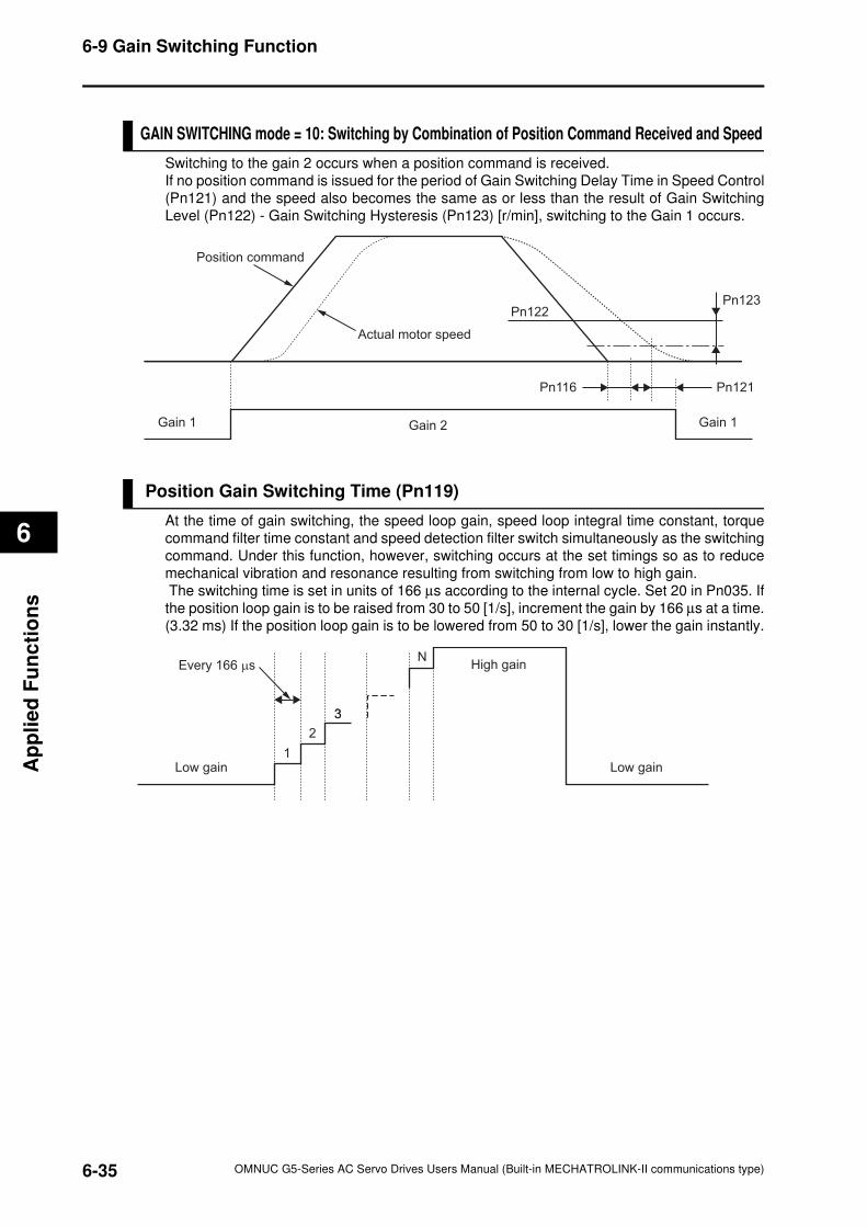
6-35
6-9 Gain Switching Function
OMNUC G5-Series AC Servo Drives Users Manual (Built-in MECHATROLINK-II communications type)
6
Ap
pli
ed
Fu
nc
tio
ns
GAIN SWITCHING mode = 10: Switching by Combination of Position Command Received and Speed
Switching to the gain 2 occurs when a position command is received.
If no position command is issued for the period of Gain Switching Delay Time in Speed Control
(Pn121) and the speed also becomes the same as or less than the result of Gain Switching
Level (Pn122) - Gain Switching Hysteresis (Pn123) [r/min], switching to the Gain 1 occurs.
Position Gain Switching Time (Pn119)
At the time of gain switching, the speed loop gain, speed loop integral time constant, torque
command filter time constant and speed detection filter switch simultaneously as the switching
command. Under this function, however, switching occurs at the set timings so as to reduce
mechanical vibration and resonance resulting from switching from low to high gain.
The switching time is set in units of 166 µs according to the internal cycle. Set 20 in Pn035. If
the position loop gain is to be raised from 30 to 50 [1/s], increment the gain by 166 µs at a time.
(3.32 ms) If the position loop gain is to be lowered from 50 to 30 [1/s], lower the gain instantly.
Gain 1 Gain 1Gain 2
Pn121Pn116
Pn122Pn123
Actual motor speed
Position command
Low gain Low gain
High gainEvery 166 µs
1
2
3
N
3
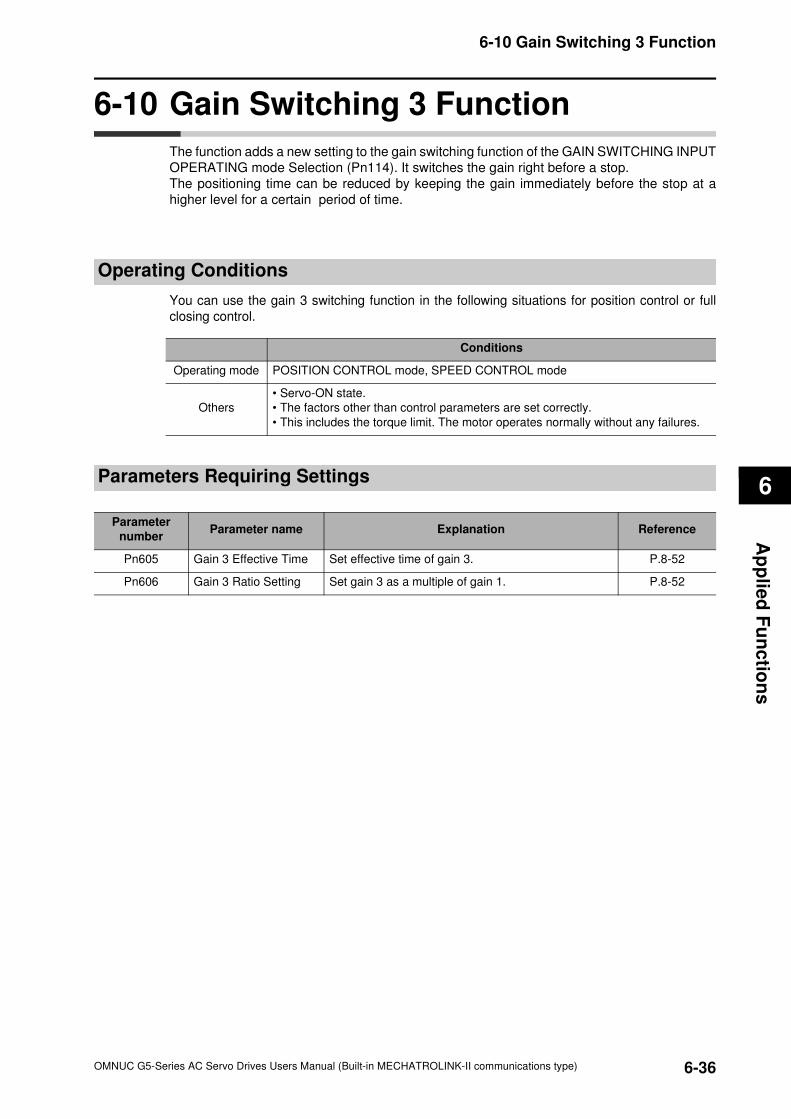
6
6-36
6-10 Gain Switching 3 Function
OMNUC G5-Series AC Servo Drives Users Manual (Built-in MECHATROLINK-II communications type)
Ap
plie
d F
un
ctio
ns
6-10 Gain Switching 3 Function
The function adds a new setting to the gain switching function of the GAIN SWITCHING INPUT
OPERATING mode Selection (Pn114). It switches the gain right before a stop.
The positioning time can be reduced by keeping the gain immediately before the stop at a
higher level for a certain period of time.
Operating Conditions
You can use the gain 3 switching function in the following situations for position control or full
closing control.
Parameters Requiring Settings
Conditions
Operating mode POSITION CONTROL mode, SPEED CONTROL mode
Others
• Servo-ON state.
• The factors other than control parameters are set correctly.
• This includes the torque limit. The motor operates normally without any failures.
Parameter
numberParameter name Explanation Reference
Pn605 Gain 3 Effective Time Set effective time of gain 3. P.8-52
Pn606 Gain 3 Ratio Setting Set gain 3 as a multiple of gain 1. P.8-52
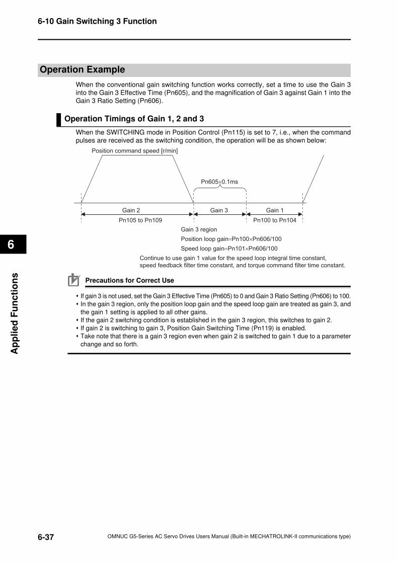
6-37
6-10 Gain Switching 3 Function
OMNUC G5-Series AC Servo Drives Users Manual (Built-in MECHATROLINK-II communications type)
6
Ap
pli
ed
Fu
nc
tio
ns
Operation Example
When the conventional gain switching function works correctly, set a time to use the Gain 3
into the Gain 3 Effective Time (Pn605), and the magnification of Gain 3 against Gain 1 into the
Gain 3 Ratio Setting (Pn606).
Operation Timings of Gain 1, 2 and 3
When the SWITCHING mode in Position Control (Pn115) is set to 7, i.e., when the command
pulses are received as the switching condition, the operation will be as shown below:
Precautions for Correct Use
If gain 3 is not used, set the Gain 3 Effective Time (Pn605) to 0 and Gain 3 Ratio Setting (Pn606) to 100.
In the gain 3 region, only the position loop gain and the speed loop gain are treated as gain 3, and
the gain 1 setting is applied to all other gains.
If the gain 2 switching condition is established in the gain 3 region, this switches to gain 2.
If gain 2 is switching to gain 3, Position Gain Switching Time (Pn119) is enabled.
Take note that there is a gain 3 region even when gain 2 is switched to gain 1 due to a parameter
change and so forth.
Gain 2 Gain 3 Gain 1
Position command speed [r/min]
Pn605×0.1ms
Pn105 to Pn109
Gain 3 region
Position loop gain=Pn100×Pn606/100
Speed loop gain=Pn101×Pn606/100
Continue to use gain 1 value for the speed loop integral time constant,
speed feedback filter time constant, and torque command filter time constant.
Pn100 to Pn104
7
7
Safety Function
This function stops the motor based on a signal from a Safety Controller or safety
sensor.
An outline of the function is explained together with operation and connection
example.
7-1 Safe Torque OFF (STO) Function................................7-1
7-2 Operation Example .......................................................7-4
7-3 Connection Examples ..................................................7-6
OMNUC G5-Series AC Servo Drives Users Manual (Built-in MECHATROLINK-II communications type)
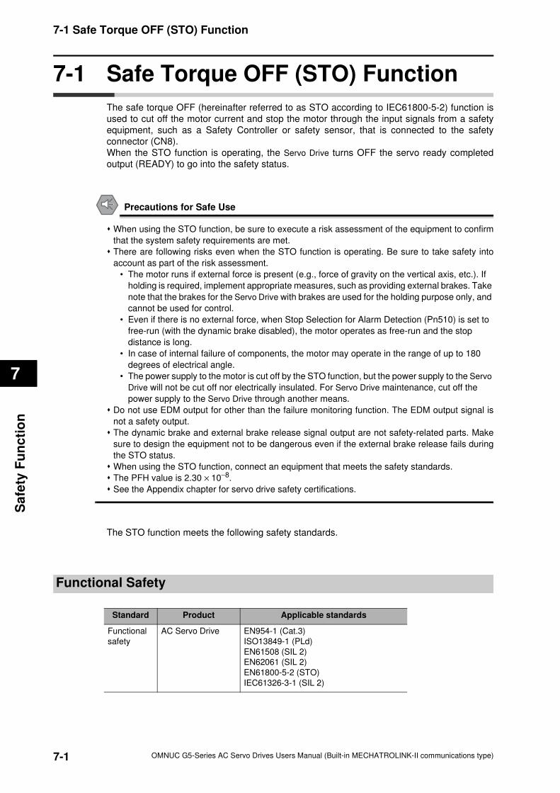
7-1 Safe Torque OFF (STO) Function
7
Sa
fety
Fu
nc
tio
n
7-1 Safe Torque OFF (STO) Function
The safe torque OFF (hereinafter referred to as STO according to IEC61800-5-2) function is
used to cut off the motor current and stop the motor through the input signals from a safety
equipment, such as a Safety Controller or safety sensor, that is connected to the safety
connector (CN8).
When the STO function is operating, the Servo Drive turns OFF the servo ready completed
output (READY) to go into the safety status.
Precautions for Safe Use
When using the STO function, be sure to execute a risk assessment of the equipment to confirm
that the system safety requirements are met.
There are following risks even when the STO function is operating. Be sure to take safety into
account as part of the risk assessment.
• The motor runs if external force is present (e.g., force of gravity on the vertical axis, etc.). If
holding is required, implement appropriate measures, such as providing external brakes. Take
note that the brakes for the Servo Drive with brakes are used for the holding purpose only, and
cannot be used for control.
• Even if there is no external force, when Stop Selection for Alarm Detection (Pn510) is set to
free-run (with the dynamic brake disabled), the motor operates as free-run and the stop
distance is long.
• In case of internal failure of components, the motor may operate in the range of up to 180
degrees of electrical angle.
• The power supply to the motor is cut off by the STO function, but the power supply to the Servo
Drive will not be cut off nor electrically insulated. For Servo Drive maintenance, cut off the
power supply to the Servo Drive through another means.
Do not use EDM output for other than the failure monitoring function. The EDM output signal is
not a safety output.
The dynamic brake and external brake release signal output are not safety-related parts. Make
sure to design the equipment not to be dangerous even if the external brake release fails during
the STO status.
When using the STO function, connect an equipment that meets the safety standards.
The PFH value is 2.30 × 10⁻⁸.
See the Appendix chapter for servo drive safety certifications.
The STO function meets the following safety standards.
Functional Safety
Standard Product Applicable standards
Functional
safety
AC Servo Drive EN954-1 (Cat.3)
ISO13849-1 (PLd)
EN61508 (SIL 2)
EN62061 (SIL 2)
EN61800-5-2 (STO)
IEC61326-3-1 (SIL 2)
7-1 OMNUC G5-Series AC Servo Drives Users Manual (Built-in MECHATROLINK-II communications type)
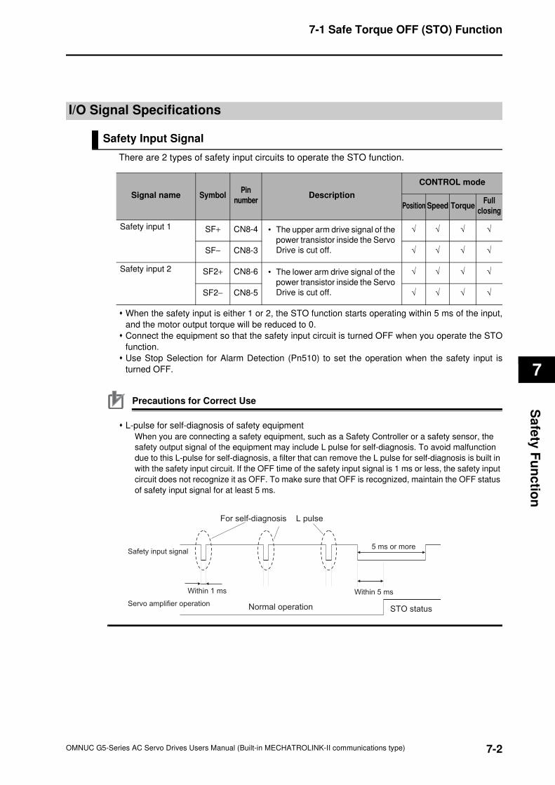
7-1 Safe Torque OFF (STO) Function
7
Sa
fety
Fu
nc
tion
I/O Signal Specifications
Safety Input Signal
There are 2 types of safety input circuits to operate the STO function.
When the safety input is either 1 or 2, the STO function starts operating within 5 ms of the input,
and the motor output torque will be reduced to 0.
Connect the equipment so that the safety input circuit is turned OFF when you operate the STO
function.
Use Stop Selection for Alarm Detection (Pn510) to set the operation when the safety input is
turned OFF.
Precautions for Correct Use
L-pulse for self-diagnosis of safety equipment
When you are connecting a safety equipment, such as a Safety Controller or a safety sensor, the
safety output signal of the equipment may include L pulse for self-diagnosis. To avoid malfunction
due to this L-pulse for self-diagnosis, a filter that can remove the L pulse for self-diagnosis is built in
with the safety input circuit. If the OFF time of the safety input signal is 1 ms or less, the safety input
circuit does not recognize it as OFF. To make sure that OFF is recognized, maintain the OFF status
of safety input signal for at least 5 ms.
Signal name SymbolPin
numberDescription
CONTROL mode
Position Speed TorqueFull
closing
Safety input 1 SF+ CN8-4 • The upper arm drive signal of the
power transistor inside the Servo
Drive is cut off.
√ √ √ √
SF− CN8-3 √ √ √ √
Safety input 2 SF2+ CN8-6 • The lower arm drive signal of the
power transistor inside the Servo
Drive is cut off.
√ √ √ √
SF2− CN8-5 √ √ √ √
For self-diagnosis L pulse
Within 1 ms Within 5 ms
Normal operation STO status
Safety input signal
Servo amplifier operation
5 ms or more
7-2OMNUC G5-Series AC Servo Drives Users Manual (Built-in MECHATROLINK-II communications type)
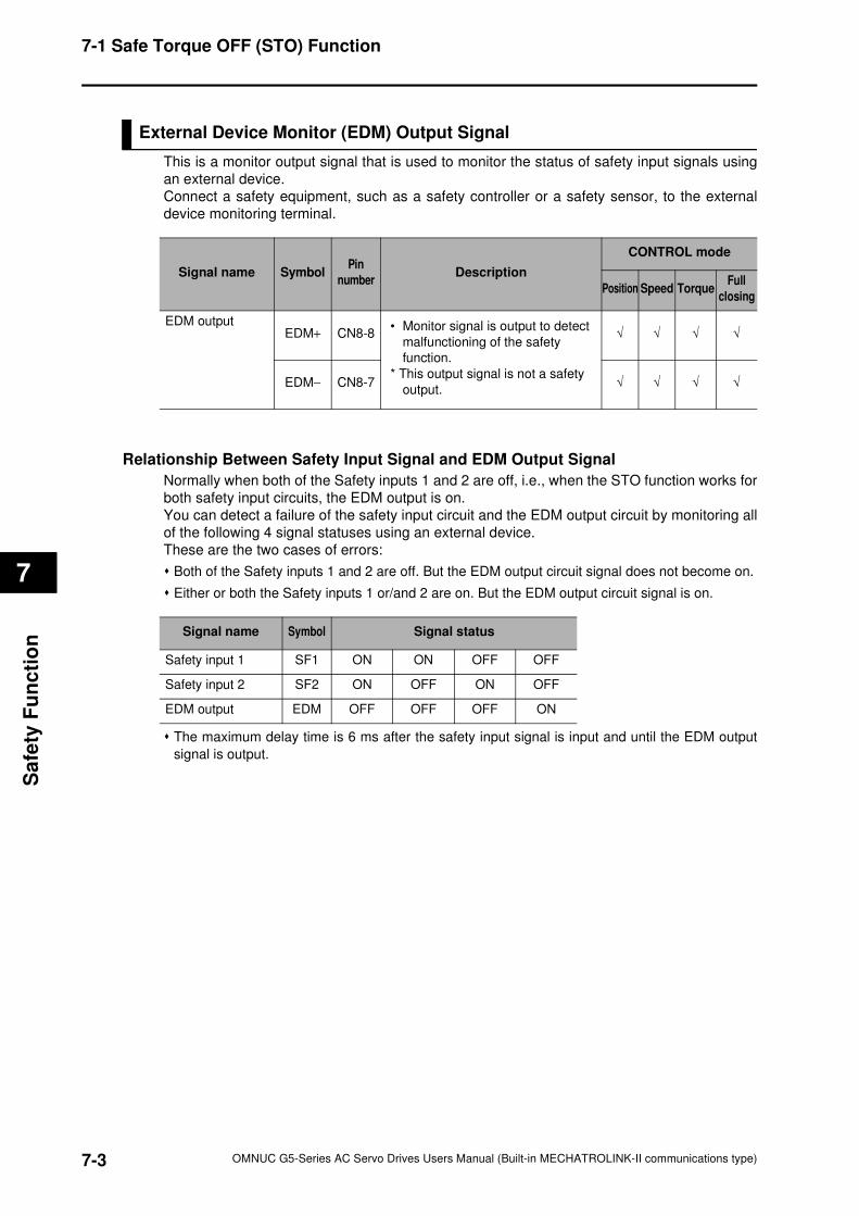
7-1 Safe Torque OFF (STO) Function
7
Sa
fety
Fu
nc
tio
n
External Device Monitor (EDM) Output Signal
This is a monitor output signal that is used to monitor the status of safety input signals using
an external device.
Connect a safety equipment, such as a safety controller or a safety sensor, to the external
device monitoring terminal.
Relationship Between Safety Input Signal and EDM Output Signal
Normally when both of the Safety inputs 1 and 2 are off, i.e., when the STO function works for
both safety input circuits, the EDM output is on.
You can detect a failure of the safety input circuit and the EDM output circuit by monitoring all
of the following 4 signal statuses using an external device.
These are the two cases of errors:
Both of the Safety inputs 1 and 2 are off. But the EDM output circuit signal does not become on.
Either or both the Safety inputs 1 or/and 2 are on. But the EDM output circuit signal is on.
The maximum delay time is 6 ms after the safety input signal is input and until the EDM output
signal is output.
Signal name SymbolPin
numberDescription
CONTROL mode
Position Speed TorqueFull
closing
EDM outputEDM+ CN8-8
• Monitor signal is output to detect
malfunctioning of the safety
function.
* This output signal is not a safety
output.
√ √ √ √
EDM− CN8-7 √ √ √ √
Signal name Symbol Signal status
Safety input 1 SF1 ON ON OFF OFF
Safety input 2 SF2 ON OFF ON OFF
EDM output EDM OFF OFF OFF ON
7-3 OMNUC G5-Series AC Servo Drives Users Manual (Built-in MECHATROLINK-II communications type)
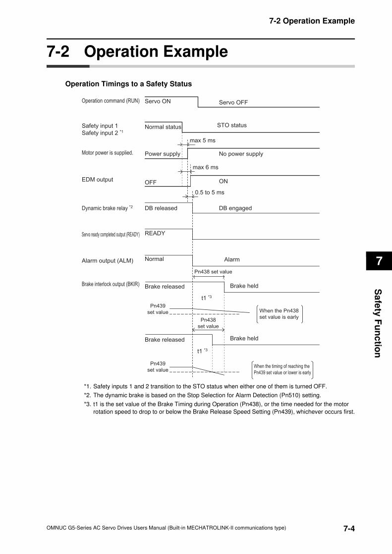
7-2 Operation Example
7
Sa
fety
Fu
nc
tion
7-2 Operation Example
Operation Timings to a Safety Status
*1. Safety inputs 1 and 2 transition to the STO status when either one of them is turned OFF.
*2. The dynamic brake is based on the Stop Selection for Alarm Detection (Pn510) setting.
*3. t1 is the set value of the Brake Timing during Operation (Pn438), or the time needed for the motor
rotation speed to drop to or below the Brake Release Speed Setting (Pn439), whichever occurs first.
Normal status
DB engaged
Brake released
DB released
Pn439
set value
Pn438
set value
t1 *3
Pn439
set value
When the Pn438
set value is early
When the timing of reaching the
Pn439 set value or lower is early
READY
Normal
Pn438 set value
t1 *3
Alarm
Brake held
Brake released Brake held
STO statusSafety input 1
Safety input 2 *1
No power supplyPower supply
max 5 ms
Motor power is supplied.
Dynamic brake relay *2
Brake interlock output (BKIR)
Servo ready completed output (READY)
Alarm output (ALM)
Operation command (RUN) Servo ON Servo OFF
ONOFF
max 6 ms
EDM output
0.5 to 5 ms
7-4OMNUC G5-Series AC Servo Drives Users Manual (Built-in MECHATROLINK-II communications type)
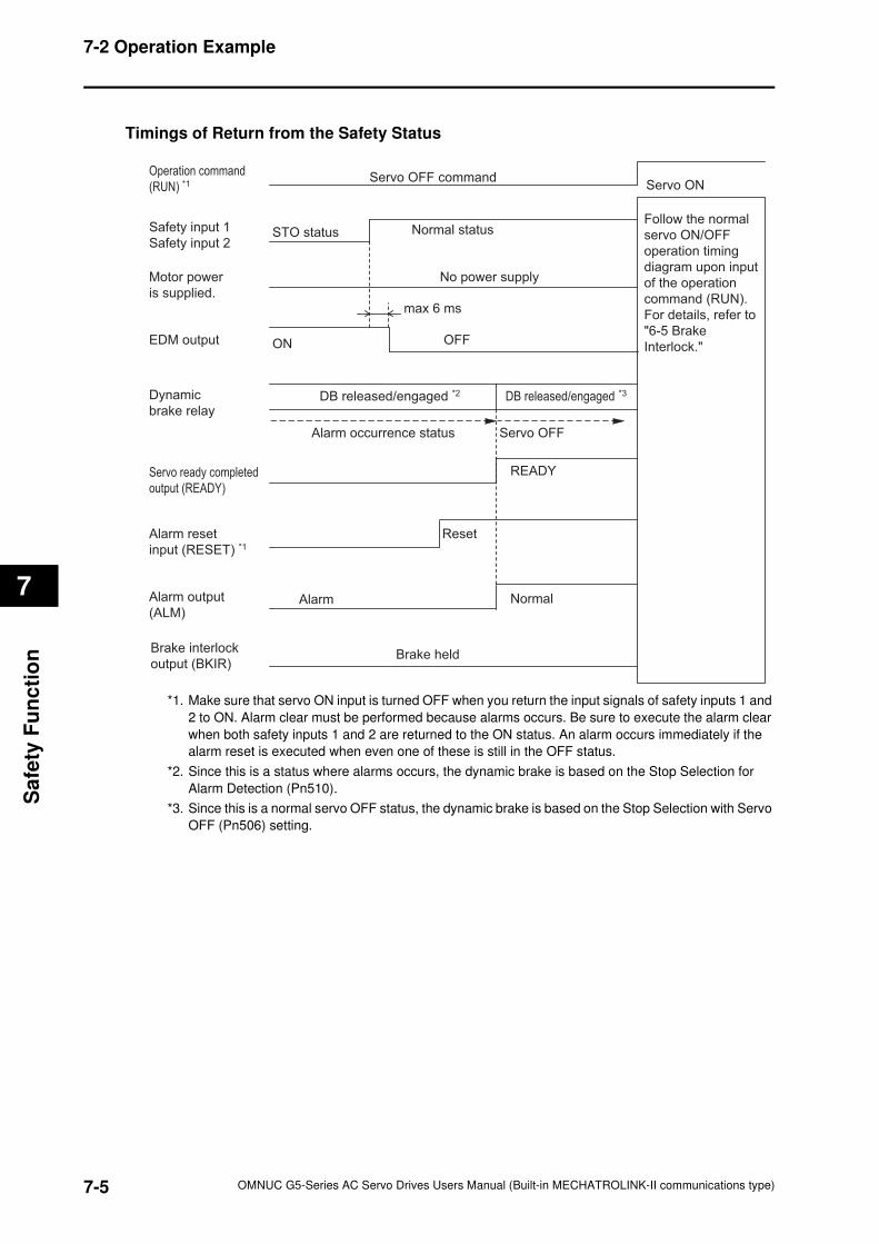
7-2 Operation Example
7
Sa
fety
Fu
nc
tio
n
Timings of Return from the Safety Status
*1. Make sure that servo ON input is turned OFF when you return the input signals of safety inputs 1 and
2 to ON. Alarm clear must be performed because alarms occurs. Be sure to execute the alarm clear
when both safety inputs 1 and 2 are returned to the ON status. An alarm occurs immediately if the
alarm reset is executed when even one of these is still in the OFF status.
*2. Since this is a status where alarms occurs, the dynamic brake is based on the Stop Selection for
Alarm Detection (Pn510).
*3. Since this is a normal servo OFF status, the dynamic brake is based on the Stop Selection with Servo
OFF (Pn506) setting.
STO status Normal status
Servo ONServo OFF command
No power supply
max 6 ms
READY
Alarm
Brake held
Reset
Normal
DB released/engaged *2
Servo OFF
DB released/engaged *3
Alarm occurrence status
Safety input 1
Safety input 2
Operation command
(RUN) *1
Brake interlock
output (BKIR)
Motor power
is supplied.
Servo ready completed
output (READY)
Alarm output
(ALM)
Alarm reset
input (RESET) *1
Dynamic
brake relay
EDM output ON OFF
Follow the normal
servo ON/OFF
operation timing
diagram upon input
of the operation
command (RUN).
For details, refer to
"6-5 Brake
Interlock."
7-5 OMNUC G5-Series AC Servo Drives Users Manual (Built-in MECHATROLINK-II communications type)
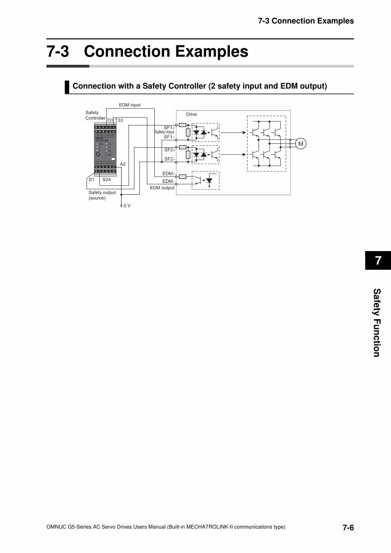
7-3 Connection Examples
7
Sa
fety
Fu
nc
tion
7-3 Connection Examples
Connection with a Safety Controller (2 safety input and EDM output)
EDM output
SF1+
SF2+
SF2−
EDM+
EDM−
M
SF1−
PWR
ERR
G9SX-AD
EI
T2
ED
T1
FB
S1 S24
T31
Safety output
(source)
Safety
Controller
0 V
A2
EDM input
Drive
Safety input
T33
7-6OMNUC G5-Series AC Servo Drives Users Manual (Built-in MECHATROLINK-II communications type)

8
8
Parameters Details
AccuraxThis chapter explains the set value and contents of setting of each parameter.
8-1 Basic Parameters..........................................................8-1
8-2 Gain Parameters ...........................................................8-8
8-3 Vibration Suppression Parameters...........................8-20
8-4 Analog Control Parameters .......................................8-25
8-5 Interface Monitor Setting Parameters.......................8-31
8-6 Extended Parameters .................................................8-42
8-7 Special Parameters.....................................................8-52
OMNUC G5-Series AC Servo Drives Users Manual (Built-in MECHATROLINK-II communications type)
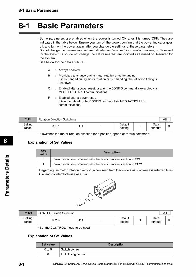
8-1 Basic Parameters
8
Pa
ram
ete
rs D
eta
ils
8-1 Basic Parameters
Some parameters are enabled when the power is turned ON after it is turned OFF. They are
indicated in the table below. Ensure you turn off the power, confirm that the power indicator goes
off, and turn on the power again, after you change the settings of these parameters.
Do not change the parameters that are indicated as Reserved for manufacturer use, or Reserved
for the system. Also, do not change the set values that are indicted as Unused or Reserved for
the system.
See below for the data attributes.
It switches the motor rotation direction for a position, speed or torque command.
Explanation of Set Values
Regarding the motor rotation direction, when seen from load-side axis, clockwise is referred to as
CW and counterclockwise as CCW.
Set the CONTROL mode to be used.
Explanation of Set Values
A : Always enabled
B : Prohibited to change during motor rotation or commanding.
If it is changed during motor rotation or commanding, the reflection timing is
unknown.
C : Enabled after a power reset, or after the CONFIG command is executed via
MECHATROLINK-II communications.
R : Enabled after a power reset.
It is not enabled by the CONFIG command via MECHATROLINK-II
communications.
Pn000 Rotation Direction Switching
Setting
range0 to 1 Unit −
Default
setting1
Data
attributeC
All
Set
valueDescription
0 Forward direction command sets the motor rotation direction to CW.
1 Forward direction command sets the motor rotation direction to CCW.
CW
CCW
Pn001 CONTROL mode Selection
Setting
range0 to 6 Unit −
Default
setting0
Data
attributeR
All
Set value Description
0 to 5 Switch control
6 Full closing control
8-1 OMNUC G5-Series AC Servo Drives Users Manual (Built-in MECHATROLINK-II communications type)
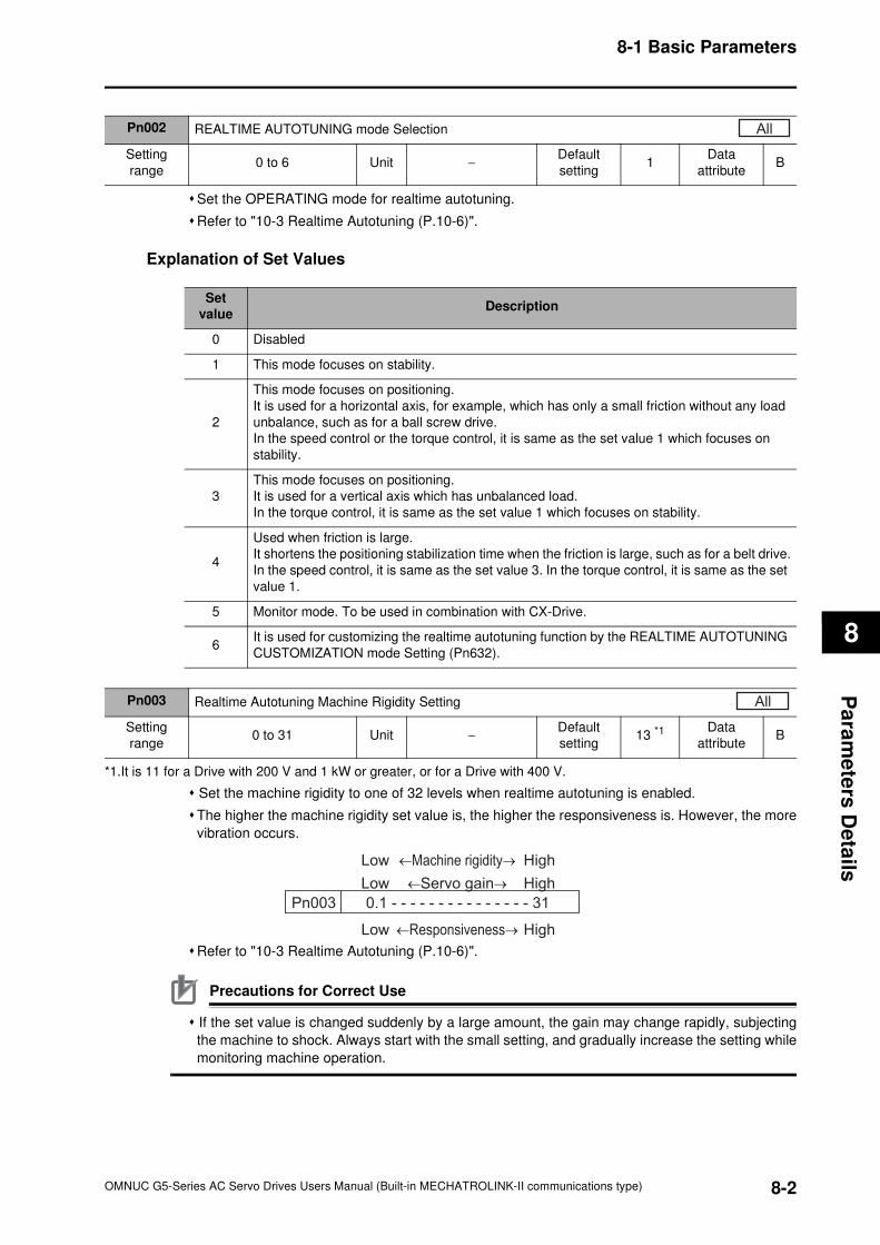
8-1 Basic Parameters
8
Pa
ram
ete
rs D
eta
ils
Set the OPERATING mode for realtime autotuning.
Refer to "10-3 Realtime Autotuning (P.10-6)".
Explanation of Set Values
*1.It is 11 for a Drive with 200 V and 1 kW or greater, or for a Drive with 400 V.
Set the machine rigidity to one of 32 levels when realtime autotuning is enabled.
The higher the machine rigidity set value is, the higher the responsiveness is. However, the more
vibration occurs.
Refer to "10-3 Realtime Autotuning (P.10-6)".
Precautions for Correct Use
If the set value is changed suddenly by a large amount, the gain may change rapidly, subjecting
the machine to shock. Always start with the small setting, and gradually increase the setting while
monitoring machine operation.
Pn002 REALTIME AUTOTUNING mode Selection
Setting
range0 to 6 Unit −
Default
setting1
Data
attributeB
All
Set
valueDescription
0 Disabled
1 This mode focuses on stability.
2
This mode focuses on positioning.
It is used for a horizontal axis, for example, which has only a small friction without any load
unbalance, such as for a ball screw drive.
In the speed control or the torque control, it is same as the set value 1 which focuses on
stability.
3
This mode focuses on positioning.
It is used for a vertical axis which has unbalanced load.
In the torque control, it is same as the set value 1 which focuses on stability.
4
Used when friction is large.
It shortens the positioning stabilization time when the friction is large, such as for a belt drive.
In the speed control, it is same as the set value 3. In the torque control, it is same as the set
value 1.
5 Monitor mode. To be used in combination with CX-Drive.
6It is used for customizing the realtime autotuning function by the REALTIME AUTOTUNING
CUSTOMIZATION mode Setting (Pn632).
Pn003 Realtime Autotuning Machine Rigidity Setting
Setting
range0 to 31 Unit −
Default
setting13 *1
Data
attributeB
All
Low
Low
Low
←Machine rigidity→
←Servo gain→
←Responsiveness→
High
High
High
0.1 - - - - - - - - - - - - - - - 31 Pn003
8-2OMNUC G5-Series AC Servo Drives Users Manual (Built-in MECHATROLINK-II communications type)
8-1 Basic Parameters
8
Pa
ram
ete
rs D
eta
ils
Set the load inertia as a percentage of the motor rotor inertia.
Pn004 = (Load inertia / Rotor inertia) × 100%
When realtime autotuning is enabled, the inertia ratio is continuously estimated and saved in
EEPROM every 30 minutes.
If the inertia ratio is set correctly, the setting unit for the Speed Loop Gain 1 (Pn101) and Speed
Loop Gain 2 (Pn106) is Hz.
If the Inertia Ratio (Pn004) is set larger than the actual value, the setting for speed loop gain
increases. If the Inertia Ratio (Pn004) is set smaller than the actual value, the setting for speed
loop gain decreases.
Pn004 Inertia Ratio
Setting
range0 to 10,000 Unit %
Default
setting300
Data
attributeB
All
Pn005 Unused
Setting
range− Unit −
Default
setting
Data
attribute−
All
Pn006 Unused
Setting
range− Unit −
Default
setting
Data
attribute−
All
Pn007 Unused
Setting
range− Unit −
Default
setting
Data
attribute−
All
Pn008 Unused
Setting
range− Unit −
Default
setting
Data
attribute−
All
8-3 OMNUC G5-Series AC Servo Drives Users Manual (Built-in MECHATROLINK-II communications type)
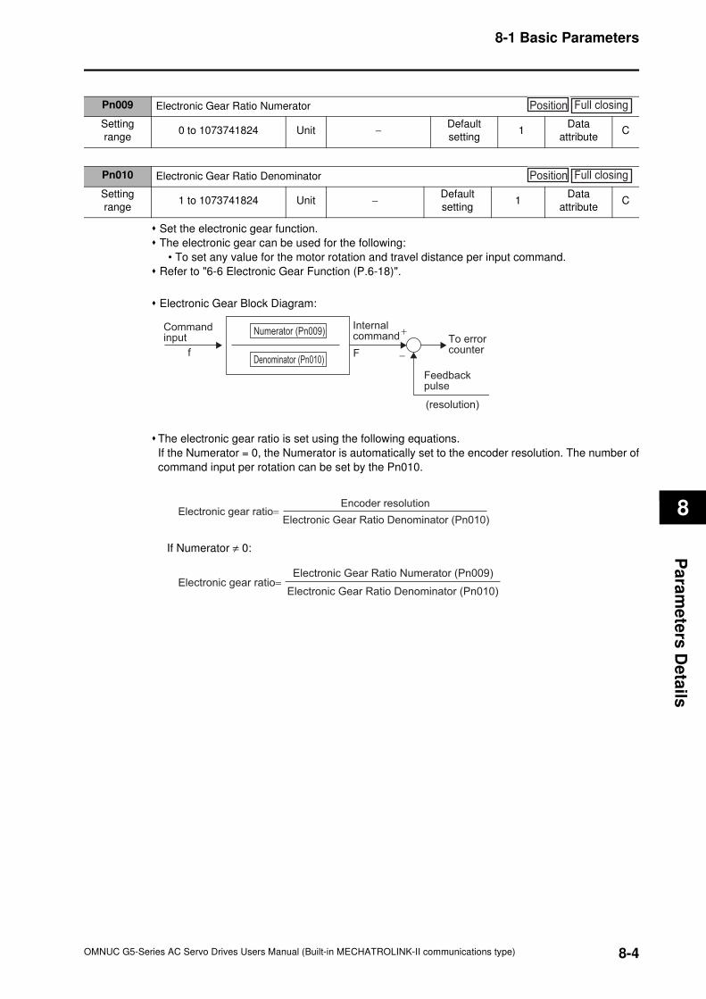
8-1 Basic Parameters
8
Pa
ram
ete
rs D
eta
ils
Set the electronic gear function.
The electronic gear can be used for the following:
• To set any value for the motor rotation and travel distance per input command.
Refer to "6-6 Electronic Gear Function (P.6-18)".
Electronic Gear Block Diagram:
The electronic gear ratio is set using the following equations.
If the Numerator = 0, the Numerator is automatically set to the encoder resolution. The number of
command input per rotation can be set by the Pn010.
If Numerator ≠ 0:
Pn009 Electronic Gear Ratio Numerator
Setting
range0 to 1073741824 Unit −
Default
setting1
Data
attributeC
Position Full closing
Pn010 Electronic Gear Ratio Denominator
Setting
range1 to 1073741824 Unit −
Default
setting1
Data
attributeC
Position Full closing
Command input
Internalcommand
Ff
+
−
(resolution)
Feedbackpulse
To errorcounter
Denominator (Pn010)
Numerator (Pn009)
Encoder resolution
Electronic Gear Ratio Denominator (Pn010)Electronic gear ratio=
Electronic Gear Ratio Numerator (Pn009)
Electronic Gear Ratio Denominator (Pn010)Electronic gear ratio=
8-4OMNUC G5-Series AC Servo Drives Users Manual (Built-in MECHATROLINK-II communications type)
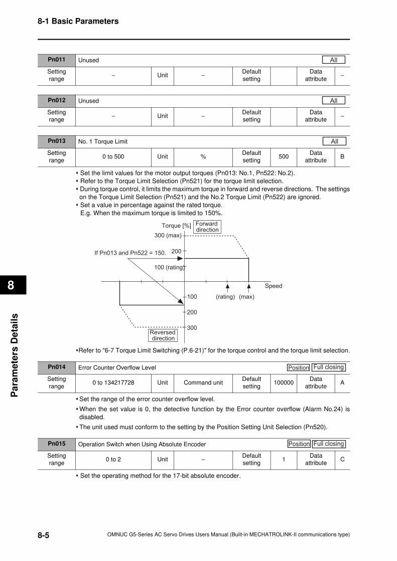
8-1 Basic Parameters
8
Pa
ram
ete
rs D
eta
ils
Set the limit values for the motor output torques (Pn013: No.1, Pn522: No.2).
Refer to the Torque Limit Selection (Pn521) for the torque limit selection.
During torque control, it limits the maximum torque in forward and reverse directions. The settings
on the Torque Limit Selection (Pn521) and the No.2 Torque Limit (Pn522) are ignored.
Set a value in percentage against the rated torque.
E.g. When the maximum torque is limited to 150%.
Refer to "6-7 Torque Limit Switching (P.6-21)" for the torque control and the torque limit selection.
Set the range of the error counter overflow level.
When the set value is 0, the detective function by the Error counter overflow (Alarm No.24) is
disabled.
The unit used must conform to the setting by the Position Setting Unit Selection (Pn520).
Set the operating method for the 17-bit absolute encoder.
Pn011 Unused
Setting
range− Unit −
Default
setting
Data
attribute−
All
Pn012 Unused
Setting
range− Unit −
Default
setting
Data
attribute−
All
Pn013 No. 1 Torque Limit
Setting
range0 to 500 Unit %
Default
setting500
Data
attributeB
All
Speed
200
100 (rating)
(rating)100
200
300
Torque [%]
300 (max)
(max)
Reversed direction
Forward direction
If Pn013 and Pn522 = 150.
Pn014 Error Counter Overflow Level
Setting
range0 to 134217728 Unit Command unit
Default
setting100000
Data
attributeA
Position Full closing
Pn015 Operation Switch when Using Absolute Encoder
Setting
range0 to 2 Unit −
Default
setting1
Data
attributeC
Position Full closing
8-5 OMNUC G5-Series AC Servo Drives Users Manual (Built-in MECHATROLINK-II communications type)
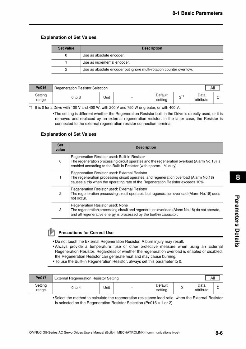
8-1 Basic Parameters
8
Pa
ram
ete
rs D
eta
ils
Explanation of Set Values
*1 It is 0 for a Drive with 100 V and 400 W, with 200 V and 750 W or greater, or with 400 V.
The setting is different whether the Regeneration Resistor built in the Drive is directly used, or it is
removed and replaced by an external regeneration resistor. In the latter case, the Resistor is
connected to the external regeneration resistor connection terminal.
Explanation of Set Values
Precautions for Correct Use
Do not touch the External Regeneration Resistor. A burn injury may result.
Always provide a temperature fuse or other protective measure when using an External
Regeneration Resistor. Regardless of whether the regeneration overload is enabled or disabled,
the Regeneration Resistor can generate heat and may cause burning.
To use the Built-in Regeneration Resistor, always set this parameter to 0.
Select the method to calculate the regeneration resistance load ratio, when the External Resistor
is selected on the Regeneration Resistor Selection (Pn016 = 1 or 2).
Set value Description
0 Use as absolute encoder.
1 Use as incremental encoder.
2 Use as absolute encoder but ignore multi-rotation counter overflow.
Pn016 Regeneration Resistor Selection
Setting
range0 to 3 Unit −
Default
setting3*1 Data
attributeC
All
Set
valueDescription
0
Regeneration Resistor used: Built-in Resistor
The regeneration processing circuit operates and the regeneration overload (Alarm No.18) is
enabled according to the Built-in Resistor (with approx. 1% duty).
1
Regeneration Resistor used: External Resistor
The regeneration processing circuit operates, and regeneration overload (Alarm No.18)
causes a trip when the operating rate of the Regeneration Resistor exceeds 10%.
2
Regeneration Resistor used: External Resistor
The regeneration processing circuit operates, but regeneration overload (Alarm No.18) does
not occur.
3
Regeneration Resistor used: None
The regeneration processing circuit and regeneration overload (Alarm No.18) do not operate,
and all regenerative energy is processed by the built-in capacitor.
Pn017 External Regeneration Resistor Setting
Setting
range0 to 4 Unit −
Default
setting0
Data
attributeC
All
8-6OMNUC G5-Series AC Servo Drives Users Manual (Built-in MECHATROLINK-II communications type)
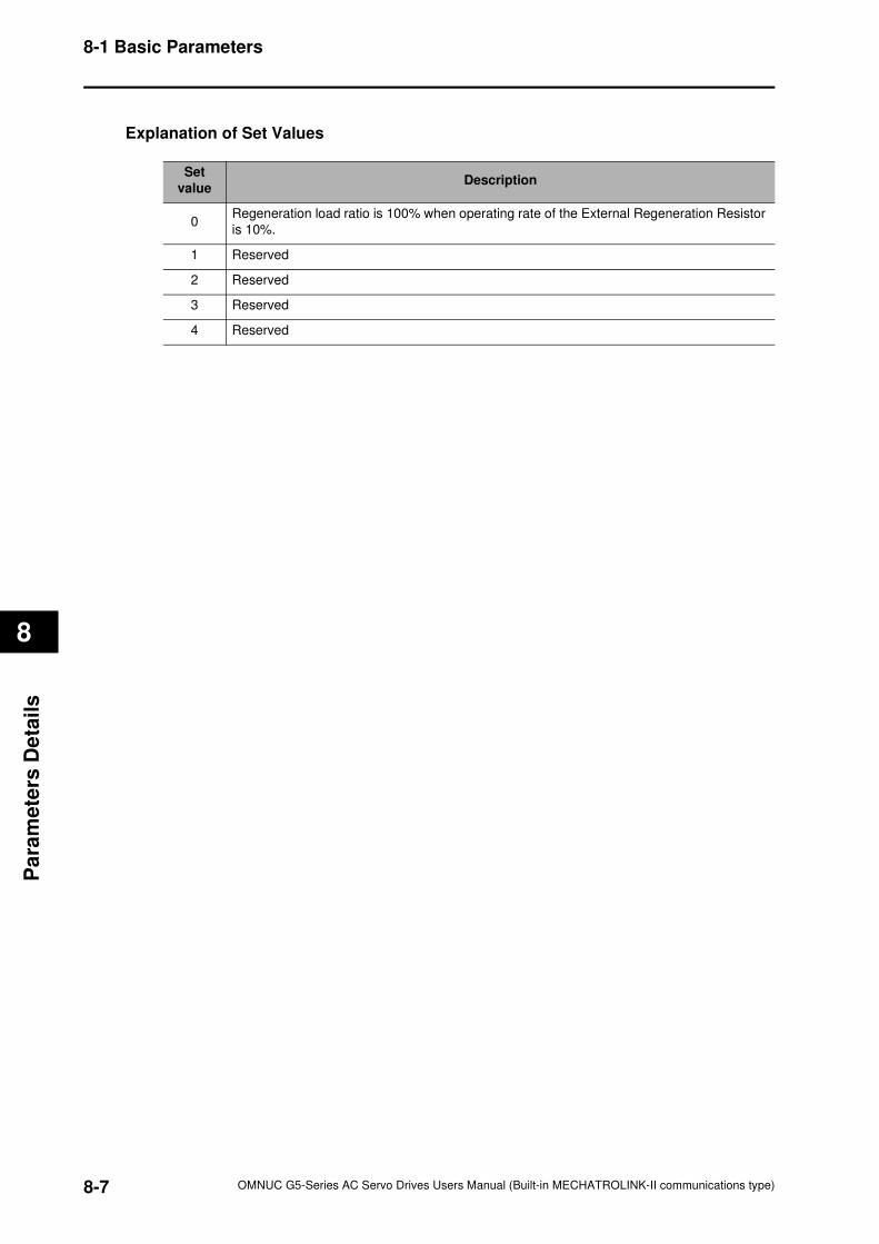
8-1 Basic Parameters
8
Pa
ram
ete
rs D
eta
ils
Explanation of Set Values
Set
valueDescription
0Regeneration load ratio is 100% when operating rate of the External Regeneration Resistor
is 10%.
1 Reserved
2 Reserved
3 Reserved
4 Reserved
8-7 OMNUC G5-Series AC Servo Drives Users Manual (Built-in MECHATROLINK-II communications type)
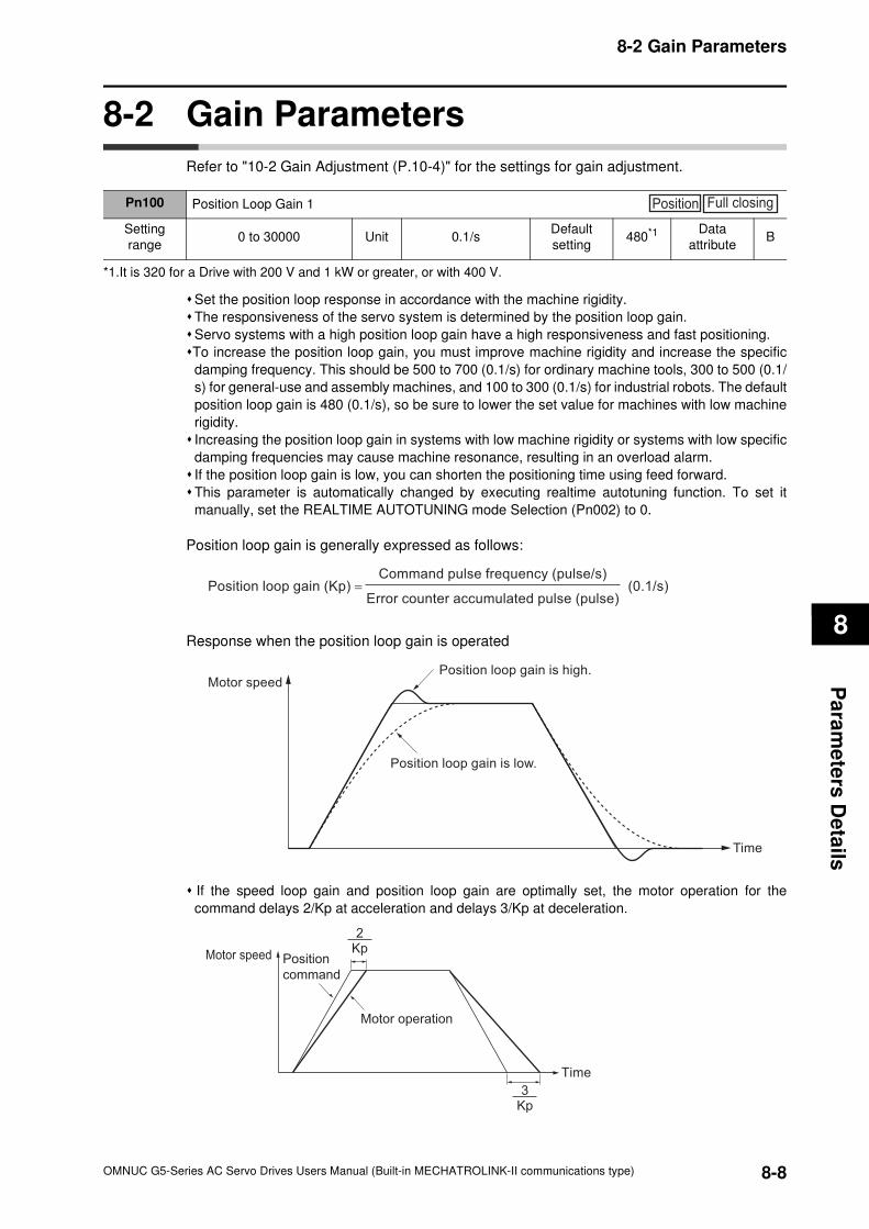
8-2 Gain Parameters
8
Pa
ram
ete
rs D
eta
ils
8-2 Gain Parameters
Refer to "10-2 Gain Adjustment (P.10-4)" for the settings for gain adjustment.
Set the position loop response in accordance with the machine rigidity.
The responsiveness of the servo system is determined by the position loop gain.
Servo systems with a high position loop gain have a high responsiveness and fast positioning.
To increase the position loop gain, you must improve machine rigidity and increase the specific
damping frequency. This should be 500 to 700 (0.1/s) for ordinary machine tools, 300 to 500 (0.1/
s) for general-use and assembly machines, and 100 to 300 (0.1/s) for industrial robots. The default
position loop gain is 480 (0.1/s), so be sure to lower the set value for machines with low machine
rigidity.
Increasing the position loop gain in systems with low machine rigidity or systems with low specific
damping frequencies may cause machine resonance, resulting in an overload alarm.
If the position loop gain is low, you can shorten the positioning time using feed forward.
This parameter is automatically changed by executing realtime autotuning function. To set it
manually, set the REALTIME AUTOTUNING mode Selection (Pn002) to 0.
Position loop gain is generally expressed as follows:
Response when the position loop gain is operated
If the speed loop gain and position loop gain are optimally set, the motor operation for the
command delays 2/Kp at acceleration and delays 3/Kp at deceleration.
Pn100 Position Loop Gain 1
Setting
range0 to 30000 Unit 0.1/s
Default
setting480*1 Data
attributeB
*1.It is 320 for a Drive with 200 V and 1 kW or greater, or with 400 V.
Position Full closing
Position loop gain (Kp) =Command pulse frequency (pulse/s)
Error counter accumulated pulse (pulse)(0.1/s)
Motor speed
Time
Position loop gain is high.
Position loop gain is low.
Kp3
Kp2
Motor speed
Time
Position
command
Motor operation
8-8OMNUC G5-Series AC Servo Drives Users Manual (Built-in MECHATROLINK-II communications type)
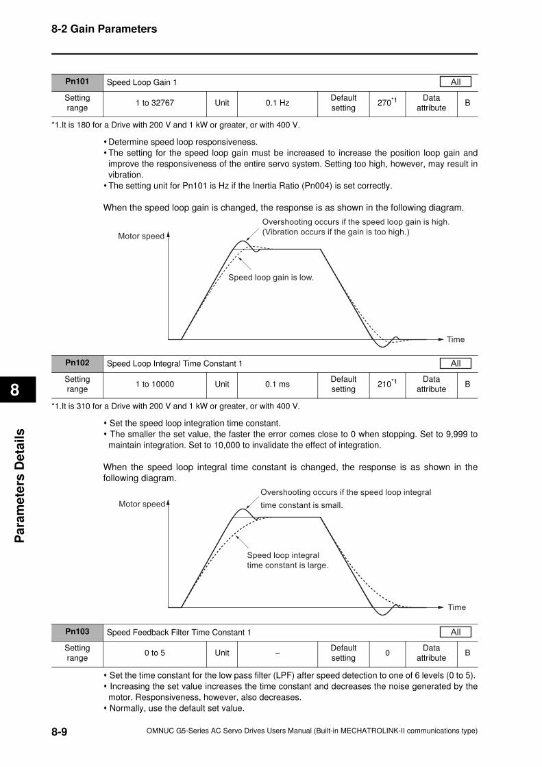
8-2 Gain Parameters
8
Pa
ram
ete
rs D
eta
ils
Determine speed loop responsiveness.
The setting for the speed loop gain must be increased to increase the position loop gain and
improve the responsiveness of the entire servo system. Setting too high, however, may result in
vibration.
The setting unit for Pn101 is Hz if the Inertia Ratio (Pn004) is set correctly.
When the speed loop gain is changed, the response is as shown in the following diagram.
Set the speed loop integration time constant.
The smaller the set value, the faster the error comes close to 0 when stopping. Set to 9,999 to
maintain integration. Set to 10,000 to invalidate the effect of integration.
When the speed loop integral time constant is changed, the response is as shown in the
following diagram.
Set the time constant for the low pass filter (LPF) after speed detection to one of 6 levels (0 to 5).
Increasing the set value increases the time constant and decreases the noise generated by the
motor. Responsiveness, however, also decreases.
Normally, use the default set value.
Pn101 Speed Loop Gain 1
Setting
range1 to 32767 Unit 0.1 Hz
Default
setting270*1 Data
attributeB
*1.It is 180 for a Drive with 200 V and 1 kW or greater, or with 400 V.
All
Motor speed
Time
Overshooting occurs if the speed loop gain is high.
(Vibration occurs if the gain is too high.)
Speed loop gain is low.
Pn102 Speed Loop Integral Time Constant 1
Setting
range1 to 10000 Unit 0.1 ms
Default
setting210*1 Data
attributeB
*1.It is 310 for a Drive with 200 V and 1 kW or greater, or with 400 V.
All
Motor speed
Time
Overshooting occurs if the speed loop integral
time constant is small.
Speed loop integral
time constant is large.
Pn103 Speed Feedback Filter Time Constant 1
Setting
range0 to 5 Unit −
Default
setting0
Data
attributeB
All
8-9 OMNUC G5-Series AC Servo Drives Users Manual (Built-in MECHATROLINK-II communications type)
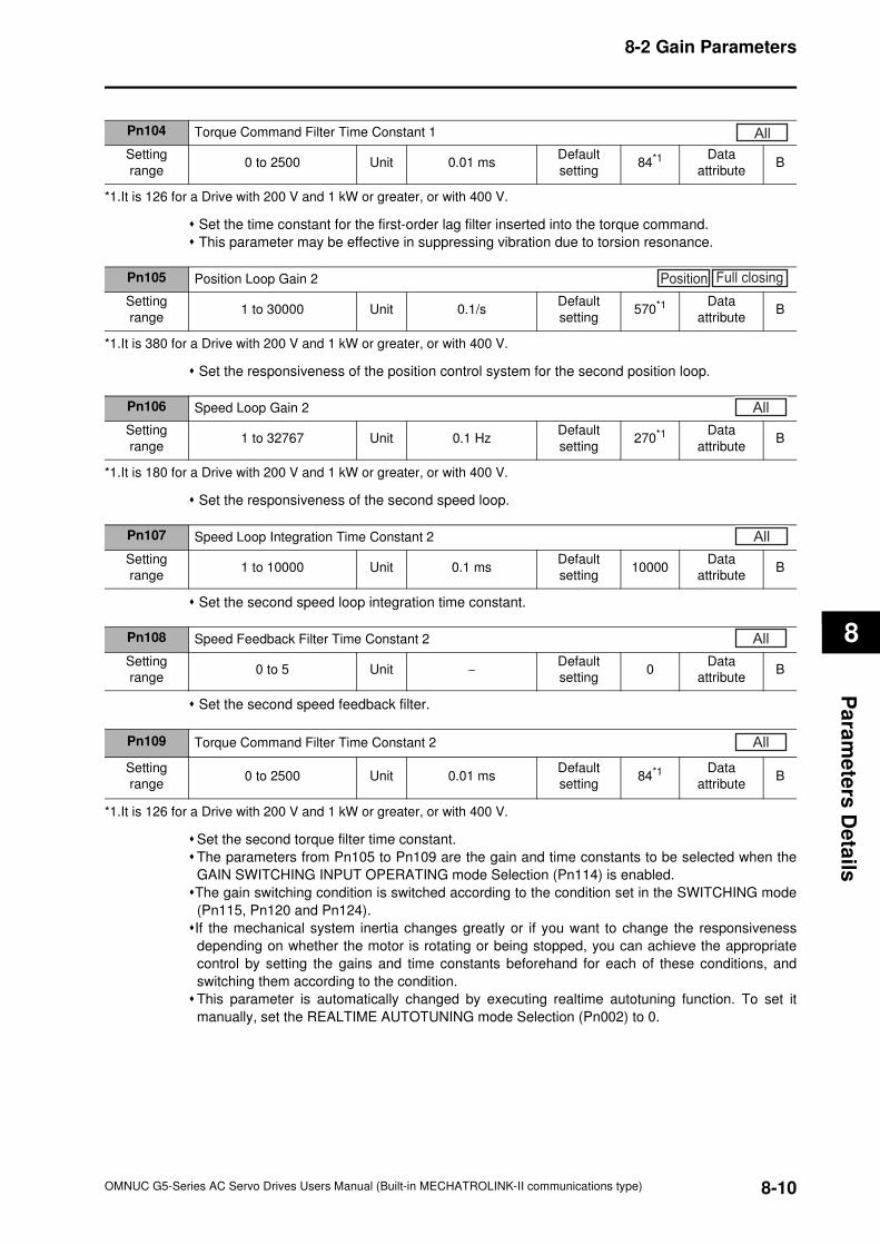
8-2 Gain Parameters
8
Pa
ram
ete
rs D
eta
ils
Set the time constant for the first-order lag filter inserted into the torque command.
This parameter may be effective in suppressing vibration due to torsion resonance.
Set the responsiveness of the position control system for the second position loop.
Set the responsiveness of the second speed loop.
Set the second speed loop integration time constant.
Set the second speed feedback filter.
Set the second torque filter time constant.
The parameters from Pn105 to Pn109 are the gain and time constants to be selected when the
GAIN SWITCHING INPUT OPERATING mode Selection (Pn114) is enabled.
The gain switching condition is switched according to the condition set in the SWITCHING mode
(Pn115, Pn120 and Pn124).
If the mechanical system inertia changes greatly or if you want to change the responsiveness
depending on whether the motor is rotating or being stopped, you can achieve the appropriate
control by setting the gains and time constants beforehand for each of these conditions, and
switching them according to the condition.
This parameter is automatically changed by executing realtime autotuning function. To set it
manually, set the REALTIME AUTOTUNING mode Selection (Pn002) to 0.
Pn104 Torque Command Filter Time Constant 1
Setting
range0 to 2500 Unit 0.01 ms
Default
setting84*1 Data
attributeB
*1.It is 126 for a Drive with 200 V and 1 kW or greater, or with 400 V.
All
Pn105 Position Loop Gain 2
Setting
range1 to 30000 Unit 0.1/s
Default
setting570*1 Data
attributeB
*1.It is 380 for a Drive with 200 V and 1 kW or greater, or with 400 V.
Position Full closing
Pn106 Speed Loop Gain 2
Setting
range1 to 32767 Unit 0.1 Hz
Default
setting270*1 Data
attributeB
*1.It is 180 for a Drive with 200 V and 1 kW or greater, or with 400 V.
All
Pn107 Speed Loop Integration Time Constant 2
Setting
range1 to 10000 Unit 0.1 ms
Default
setting10000
Data
attributeB
All
Pn108 Speed Feedback Filter Time Constant 2
Setting
range0 to 5 Unit −
Default
setting0
Data
attributeB
All
Pn109 Torque Command Filter Time Constant 2
Setting
range0 to 2500 Unit 0.01 ms
Default
setting84*1 Data
attributeB
*1.It is 126 for a Drive with 200 V and 1 kW or greater, or with 400 V.
All
8-10OMNUC G5-Series AC Servo Drives Users Manual (Built-in MECHATROLINK-II communications type)
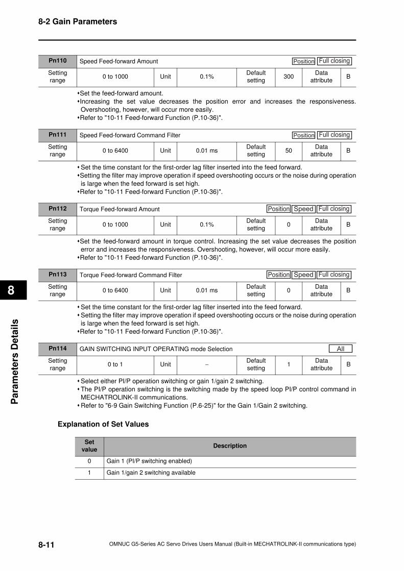
8-2 Gain Parameters
8
Pa
ram
ete
rs D
eta
ils
Set the feed-forward amount.
Increasing the set value decreases the position error and increases the responsiveness.
Overshooting, however, will occur more easily.
Refer to "10-11 Feed-forward Function (P.10-36)".
Set the time constant for the first-order lag filter inserted into the feed forward.
Setting the filter may improve operation if speed overshooting occurs or the noise during operation
is large when the feed forward is set high.
Refer to "10-11 Feed-forward Function (P.10-36)".
Set the feed-forward amount in torque control. Increasing the set value decreases the position
error and increases the responsiveness. Overshooting, however, will occur more easily.
Refer to "10-11 Feed-forward Function (P.10-36)".
Set the time constant for the first-order lag filter inserted into the feed forward.
Setting the filter may improve operation if speed overshooting occurs or the noise during operation
is large when the feed forward is set high.
Refer to "10-11 Feed-forward Function (P.10-36)".
Select either PI/P operation switching or gain 1/gain 2 switching.
The PI/P operation switching is the switching made by the speed loop PI/P control command in
MECHATROLINK-II communications.
Refer to "6-9 Gain Switching Function (P.6-25)" for the Gain 1/Gain 2 switching.
Explanation of Set Values
Pn110 Speed Feed-forward Amount
Setting
range0 to 1000 Unit 0.1%
Default
setting300
Data
attributeB
Position Full closing
Pn111 Speed Feed-forward Command Filter
Setting
range0 to 6400 Unit 0.01 ms
Default
setting50
Data
attributeB
Position Full closing
Pn112 Torque Feed-forward Amount
Setting
range0 to 1000 Unit 0.1%
Default
setting0
Data
attributeB
Position Speed Full closing
Pn113 Torque Feed-forward Command Filter
Setting
range0 to 6400 Unit 0.01 ms
Default
setting0
Data
attributeB
Position Speed Full closing
Pn114 GAIN SWITCHING INPUT OPERATING mode Selection
Setting
range0 to 1 Unit −
Default
setting1
Data
attributeB
All
Set
valueDescription
0 Gain 1 (PI/P switching enabled)
1 Gain 1/gain 2 switching available
8-11 OMNUC G5-Series AC Servo Drives Users Manual (Built-in MECHATROLINK-II communications type)
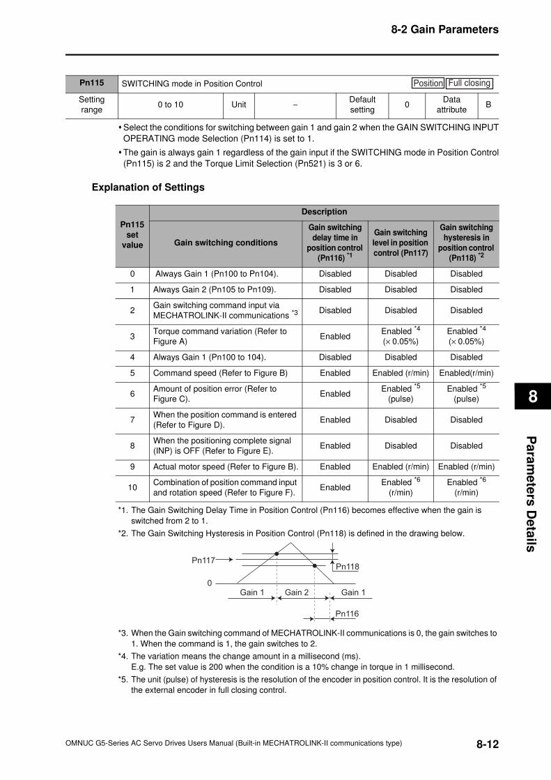
8-2 Gain Parameters
8
Pa
ram
ete
rs D
eta
ils
Select the conditions for switching between gain 1 and gain 2 when the GAIN SWITCHING INPUT
OPERATING mode Selection (Pn114) is set to 1.
The gain is always gain 1 regardless of the gain input if the SWITCHING mode in Position Control
(Pn115) is 2 and the Torque Limit Selection (Pn521) is 3 or 6.
Explanation of Settings
*1. The Gain Switching Delay Time in Position Control (Pn116) becomes effective when the gain is
switched from 2 to 1.
*2. The Gain Switching Hysteresis in Position Control (Pn118) is defined in the drawing below.
*3. When the Gain switching command of MECHATROLINK-II communications is 0, the gain switches to
1. When the command is 1, the gain switches to 2.
*4. The variation means the change amount in a millisecond (ms).
E.g. The set value is 200 when the condition is a 10% change in torque in 1 millisecond.
*5. The unit (pulse) of hysteresis is the resolution of the encoder in position control. It is the resolution of
the external encoder in full closing control.
Pn115 SWITCHING mode in Position Control
Setting
range0 to 10 Unit −
Default
setting0
Data
attributeB
Position Full closing
Pn115
set
value
Description
Gain switching conditions
Gain switching
delay time in
position control
(Pn116) *1
Gain switching
level in position
control (Pn117)
Gain switching
hysteresis in
position control
(Pn118) *2
0 Always Gain 1 (Pn100 to Pn104). Disabled Disabled Disabled
1 Always Gain 2 (Pn105 to Pn109). Disabled Disabled Disabled
2Gain switching command input via
MECHATROLINK-II communications *3Disabled Disabled Disabled
3Torque command variation (Refer to
Figure A)Enabled
Enabled *4
(× 0.05%)
Enabled *4
(× 0.05%)
4 Always Gain 1 (Pn100 to 104). Disabled Disabled Disabled
5 Command speed (Refer to Figure B) Enabled Enabled (r/min) Enabled(r/min)
6Amount of position error (Refer to
Figure C).Enabled
Enabled *5
(pulse)
Enabled *5
(pulse)
7When the position command is entered
(Refer to Figure D).Enabled Disabled Disabled
8When the positioning complete signal
(INP) is OFF (Refer to Figure E).Enabled Disabled Disabled
9 Actual motor speed (Refer to Figure B). Enabled Enabled (r/min) Enabled (r/min)
10Combination of position command input
and rotation speed (Refer to Figure F).Enabled
Enabled *6
(r/min)
Enabled *6
(r/min)
Pn117
0
Pn118
Pn116
Gain 1 Gain 2 Gain 1
8-12OMNUC G5-Series AC Servo Drives Users Manual (Built-in MECHATROLINK-II communications type)
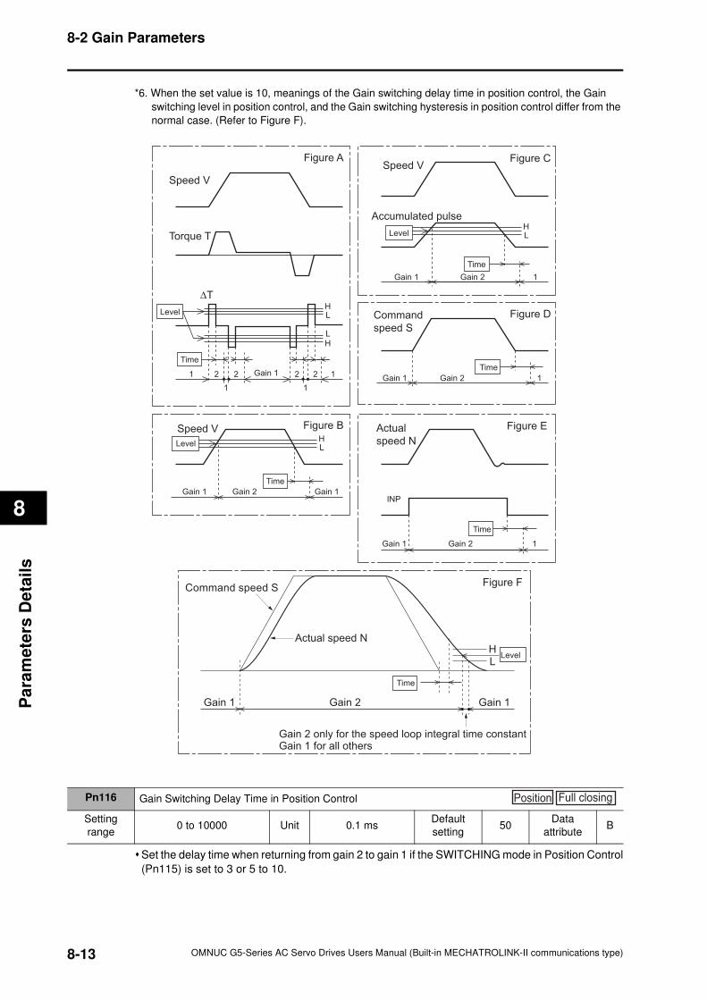
8-2 Gain Parameters
8
Pa
ram
ete
rs D
eta
ils
*6. When the set value is 10, meanings of the Gain switching delay time in position control, the Gain
switching level in position control, and the Gain switching hysteresis in position control differ from the
normal case. (Refer to Figure F).
Set the delay time when returning from gain 2 to gain 1 if the SWITCHING mode in Position Control
(Pn115) is set to 3 or 5 to 10.
HL
HL
HL
HL
Figure A
Speed V
Torque T
∆T
Time
1
1
2 2 2 2
1
1Gain 1
Figure CSpeed V
Gain 1 1Gain 2
Accumulated pulse
Level
Time
Figure DCommand
speed S
Gain 1 1Gain 2
Time
Figure EActual
speed N
INP
Gain 1 1Gain 2
Time
Figure BSpeed V
Gain 1 Gain 1Gain 2
Time
Command speed S
Gain 1 Gain 2
Actual speed N
Time
HL
Gain 1
Gain 2 only for the speed loop integral time constantGain 1 for all others
Figure F
Level
Level
Level
Pn116 Gain Switching Delay Time in Position Control
Setting
range0 to 10000 Unit 0.1 ms
Default
setting50
Data
attributeB
Position Full closing
8-13 OMNUC G5-Series AC Servo Drives Users Manual (Built-in MECHATROLINK-II communications type)
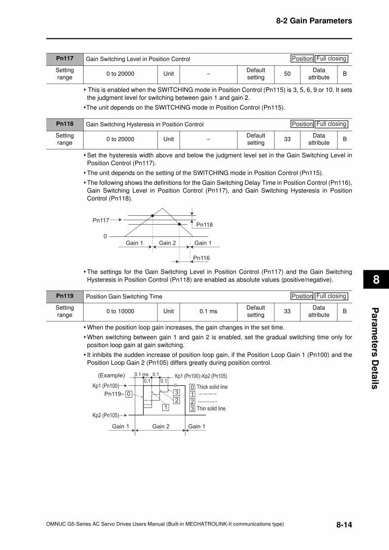
8-2 Gain Parameters
8
Pa
ram
ete
rs D
eta
ils
This is enabled when the SWITCHING mode in Position Control (Pn115) is 3, 5, 6, 9 or 10. It sets
the judgment level for switching between gain 1 and gain 2.
The unit depends on the SWITCHING mode in Position Control (Pn115).
Set the hysteresis width above and below the judgment level set in the Gain Switching Level in
Position Control (Pn117).
The unit depends on the setting of the SWITCHING mode in Position Control (Pn115).
The following shows the definitions for the Gain Switching Delay Time in Position Control (Pn116),
Gain Switching Level in Position Control (Pn117), and Gain Switching Hysteresis in Position
Control (Pn118).
The settings for the Gain Switching Level in Position Control (Pn117) and the Gain Switching
Hysteresis in Position Control (Pn118) are enabled as absolute values (positive/negative).
When the position loop gain increases, the gain changes in the set time.
When switching between gain 1 and gain 2 is enabled, set the gradual switching time only for
position loop gain at gain switching.
It inhibits the sudden increase of position loop gain, if the Position Loop Gain 1 (Pn100) and the
Position Loop Gain 2 (Pn105) differs greatly during position control.
Pn117 Gain Switching Level in Position Control
Setting
range0 to 20000 Unit −
Default
setting50
Data
attributeB
Position Full closing
Pn118 Gain Switching Hysteresis in Position Control
Setting
range0 to 20000 Unit −
Default
setting33
Data
attributeB
Position Full closing
Pn117
0
Pn118
Pn116
Gain 1 Gain 2 Gain 1
Pn119 Position Gain Switching Time
Setting
range0 to 10000 Unit 0.1 ms
Default
setting33
Data
attributeB
Position Full closing
Pn119=
Kp1 (Pn100)
0.1 ms
0.1 0.1
0.1
Kp2 (Pn105)
Gain 1
(Example)
Gain 2
Thick solid line
Thin solid line
Gain 1
00
1
12 2
3
3
Kp1 (Pn100)>Kp2 (Pn105)
8-14OMNUC G5-Series AC Servo Drives Users Manual (Built-in MECHATROLINK-II communications type)
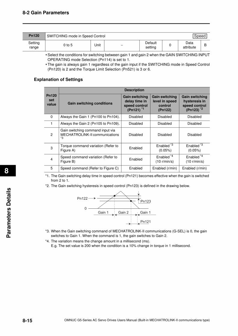
8-2 Gain Parameters
8
Pa
ram
ete
rs D
eta
ils
Select the conditions for switching between gain 1 and gain 2 when the GAIN SWITCHING INPUT
OPERATING mode Selection (Pn114) is set to 1.
The gain is always gain 1 regardless of the gain input if the SWITCHING mode in Speed Control
(Pn120) is 2 and the Torque Limit Selection (Pn521) is 3 or 6.
Explanation of Settings
*1. The Gain switching delay time in speed control (Pn121) becomes effective when the gain is switched
from 2 to 1.
*2. The Gain switching hysteresis in speed control (Pn123) is defined in the drawing below.
*3. When the Gain switching command of MECHATROLINK-II communications (G-SEL) is 0, the gain
switches to Gain 1. When the command is 1, the gain switches to Gain 2.
*4. The variation means the change amount in a millisecond (ms).
E.g. The set value is 200 when the condition is a 10% change in torque in 1 millisecond.
Pn120 SWITCHING mode in Speed Control
Setting
range0 to 5 Unit −
Default
setting0
Data
attributeB
Speed
Pn120
set
value
Description
Gain switching conditions
Gain switching
delay time in
speed control
(Pn121) *1
Gain switching
level in speed
control
(Pn122)
Gain switching
hysteresis in
speed control
(Pn123) *2
0 Always the Gain 1 (Pn100 to Pn104). Disabled Disabled Disabled
1 Always the Gain 2 (Pn105 to Pn109). Disabled Disabled Disabled
2
Gain switching command input via
MECHATROLINK-II communications *3
Disabled Disabled Disabled
3Torque command variation (Refer to
Figure A)Enabled
Enabled *3
(0.05%)
Enabled *3
(0.05%)
4Speed command variation (Refer to
Figure B)Enabled
Enabled *4
(10 r/min/s)
Enabled *4
(10 r/min/s)
5 Speed command (Refer to Figure C) Enabled Enabled (r/min) Enabled (r/min)
Pn122
0
Pn123
Pn121
Gain 1 Gain 2 Gain 1
8-15 OMNUC G5-Series AC Servo Drives Users Manual (Built-in MECHATROLINK-II communications type)
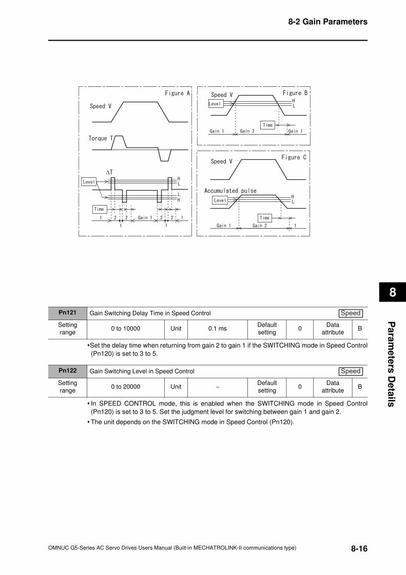
8-2 Gain Parameters
8
Pa
ram
ete
rs D
eta
ils
Set the delay time when returning from gain 2 to gain 1 if the SWITCHING mode in Speed Control
(Pn120) is set to 3 to 5.
In SPEED CONTROL mode, this is enabled when the SWITCHING mode in Speed Control
(Pn120) is set to 3 to 5. Set the judgment level for switching between gain 1 and gain 2.
The unit depends on the SWITCHING mode in Speed Control (Pn120).
∆
Pn121 Gain Switching Delay Time in Speed Control
Setting
range0 to 10000 Unit 0.1 ms
Default
setting0
Data
attributeB
Speed
Pn122 Gain Switching Level in Speed Control
Setting
range0 to 20000 Unit −
Default
setting0
Data
attributeB
Speed
8-16OMNUC G5-Series AC Servo Drives Users Manual (Built-in MECHATROLINK-II communications type)
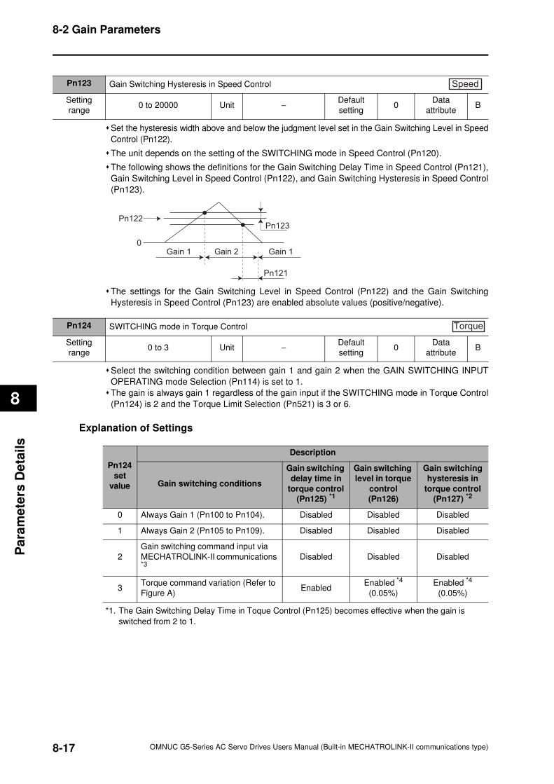
8-2 Gain Parameters
8
Pa
ram
ete
rs D
eta
ils
Set the hysteresis width above and below the judgment level set in the Gain Switching Level in Speed
Control (Pn122).
The unit depends on the setting of the SWITCHING mode in Speed Control (Pn120).
The following shows the definitions for the Gain Switching Delay Time in Speed Control (Pn121),
Gain Switching Level in Speed Control (Pn122), and Gain Switching Hysteresis in Speed Control
(Pn123).
The settings for the Gain Switching Level in Speed Control (Pn122) and the Gain Switching
Hysteresis in Speed Control (Pn123) are enabled absolute values (positive/negative).
Select the switching condition between gain 1 and gain 2 when the GAIN SWITCHING INPUT
OPERATING mode Selection (Pn114) is set to 1.
The gain is always gain 1 regardless of the gain input if the SWITCHING mode in Torque Control
(Pn124) is 2 and the Torque Limit Selection (Pn521) is 3 or 6.
Explanation of Settings
*1. The Gain Switching Delay Time in Toque Control (Pn125) becomes effective when the gain is
switched from 2 to 1.
Pn123 Gain Switching Hysteresis in Speed Control
Setting
range0 to 20000 Unit −
Default
setting0
Data
attributeB
Speed
Pn122
0
Pn123
Pn121
Gain 1 Gain 2 Gain 1
Pn124 SWITCHING mode in Torque Control
Setting
range0 to 3 Unit −
Default
setting0
Data
attributeB
Torque
Pn124
set
value
Description
Gain switching conditions
Gain switching
delay time in
torque control
(Pn125) *1
Gain switching
level in torque
control
(Pn126)
Gain switching
hysteresis in
torque control
(Pn127) *2
0 Always Gain 1 (Pn100 to Pn104). Disabled Disabled Disabled
1 Always Gain 2 (Pn105 to Pn109). Disabled Disabled Disabled
2
Gain switching command input via
MECHATROLINK-II communications *3
Disabled Disabled Disabled
3Torque command variation (Refer to
Figure A)Enabled
Enabled *4
(0.05%)
Enabled *4
(0.05%)
8-17 OMNUC G5-Series AC Servo Drives Users Manual (Built-in MECHATROLINK-II communications type)
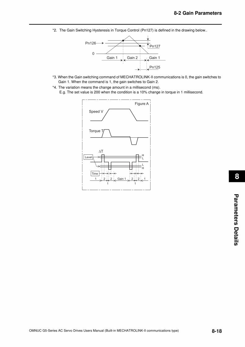
8-2 Gain Parameters
8
Pa
ram
ete
rs D
eta
ils
*2. The Gain Switching Hysteresis in Torque Control (Pn127) is defined in the drawing below..
*3. When the Gain switching command of MECHATROLINK-II communications is 0, the gain switches to
Gain 1. When the command is 1, the gain switches to Gain 2.
*4. The variation means the change amount in a millisecond (ms).
E.g. The set value is 200 when the condition is a 10% change in torque in 1 millisecond.
Pn126
0
Pn127
Pn125
Gain 1 Gain 2 Gain 1
HL
HL
Figure A
Speed V
Torque T
∆T
Time
1
1
2 2 2 2
1
1Gain 1
Level
8-18OMNUC G5-Series AC Servo Drives Users Manual (Built-in MECHATROLINK-II communications type)
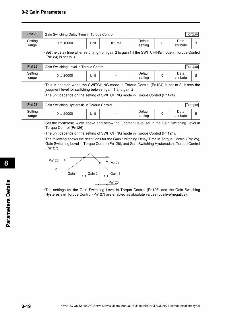
8-2 Gain Parameters
8
Pa
ram
ete
rs D
eta
ils
Set the delay time when returning from gain 2 to gain 1 if the SWITCHING mode in Torque Control
(Pn124) is set to 3.
This is enabled when the SWITCHING mode in Torque Control (Pn124) is set to 3. It sets the
judgment level for switching between gain 1 and gain 2.
The unit depends on the setting of SWITCHING mode in Torque Control (Pn124).
Set the hysteresis width above and below the judgment level set in the Gain Switching Level in
Torque Control (Pn126).
The unit depends on the setting of SWITCHING mode in Torque Control (Pn124).
The following shows the definitions for the Gain Switching Delay Time in Torque Control (Pn125),
Gain Switching Level in Torque Control (Pn126), and Gain Switching Hysteresis in Torque Control
(Pn127).
The settings for the Gain Switching Level in Torque Control (Pn126) and the Gain Switching
Hysteresis in Torque Control (Pn127) are enabled as absolute values (positive/negative).
Pn125 Gain Switching Delay Time in Torque Control
Setting
range0 to 10000 Unit 0.1 ms
Default
setting0
Data
attributeB
Torque
Pn126 Gain Switching Level in Torque Control
Setting
range0 to 20000 Unit −
Default
setting0
Data
attributeB
Torque
Pn127 Gain Switching Hysteresis in Torque Control
Setting
range0 to 20000 Unit −
Default
setting0
Data
attributeB
Torque
Pn126
0
Pn127
Pn125
Gain 1 Gain 2 Gain 1
8-19 OMNUC G5-Series AC Servo Drives Users Manual (Built-in MECHATROLINK-II communications type)
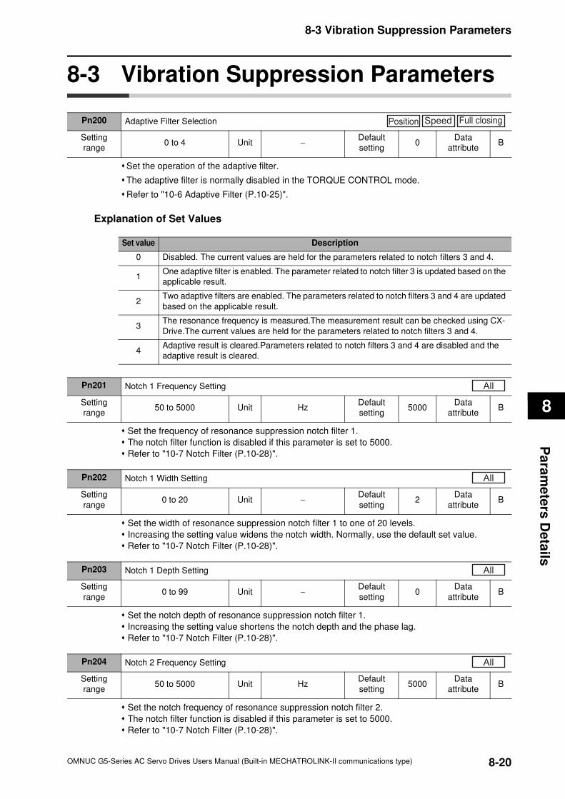
8-3 Vibration Suppression Parameters
8
Pa
ram
ete
rs D
eta
ils
8-3 Vibration Suppression Parameters
Set the operation of the adaptive filter.
The adaptive filter is normally disabled in the TORQUE CONTROL mode.
Refer to "10-6 Adaptive Filter (P.10-25)".
Explanation of Set Values
Set the frequency of resonance suppression notch filter 1.
The notch filter function is disabled if this parameter is set to 5000.
Refer to "10-7 Notch Filter (P.10-28)".
Set the width of resonance suppression notch filter 1 to one of 20 levels.
Increasing the setting value widens the notch width. Normally, use the default set value.
Refer to "10-7 Notch Filter (P.10-28)".
Set the notch depth of resonance suppression notch filter 1.
Increasing the setting value shortens the notch depth and the phase lag.
Refer to "10-7 Notch Filter (P.10-28)".
Set the notch frequency of resonance suppression notch filter 2.
The notch filter function is disabled if this parameter is set to 5000.
Refer to "10-7 Notch Filter (P.10-28)".
Pn200 Adaptive Filter Selection
Setting
range0 to 4 Unit −
Default
setting0
Data
attributeB
Position Speed Full closing
Set value Description
0 Disabled. The current values are held for the parameters related to notch filters 3 and 4.
1One adaptive filter is enabled. The parameter related to notch filter 3 is updated based on the
applicable result.
2Two adaptive filters are enabled. The parameters related to notch filters 3 and 4 are updated
based on the applicable result.
3The resonance frequency is measured.The measurement result can be checked using CX-
Drive.The current values are held for the parameters related to notch filters 3 and 4.
4Adaptive result is cleared.Parameters related to notch filters 3 and 4 are disabled and the
adaptive result is cleared.
Pn201 Notch 1 Frequency Setting
Setting
range50 to 5000 Unit Hz
Default
setting5000
Data
attributeB
All
Pn202 Notch 1 Width Setting
Setting
range0 to 20 Unit −
Default
setting2
Data
attributeB
All
Pn203 Notch 1 Depth Setting
Setting
range0 to 99 Unit −
Default
setting0
Data
attributeB
All
Pn204 Notch 2 Frequency Setting
Setting
range50 to 5000 Unit Hz
Default
setting5000
Data
attributeB
All
8-20OMNUC G5-Series AC Servo Drives Users Manual (Built-in MECHATROLINK-II communications type)
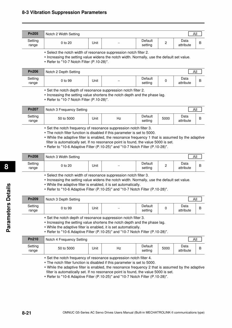
8-3 Vibration Suppression Parameters
8
Pa
ram
ete
rs D
eta
ils
Select the notch width of resonance suppression notch filter 2.
Increasing the setting value widens the notch width. Normally, use the default set value.
Refer to "10-7 Notch Filter (P.10-28)".
Set the notch depth of resonance suppression notch filter 2.
Increasing the setting value shortens the notch depth and the phase lag.
Refer to "10-7 Notch Filter (P.10-28)".
Set the notch frequency of resonance suppression notch filter 3.
The notch filter function is disabled if this parameter is set to 5000.
While the adaptive filter is enabled, the resonance frequency 1 that is assumed by the adaptive
filter is automatically set. If no resonance point is found, the value 5000 is set.
Refer to "10-6 Adaptive Filter (P.10-25)" and "10-7 Notch Filter (P.10-28)".
Select the notch width of resonance suppression notch filter 3.
Increasing the setting value widens the notch width. Normally, use the default set value.
While the adaptive filter is enabled, it is set automatically.
Refer to "10-6 Adaptive Filter (P.10-25)" and "10-7 Notch Filter (P.10-28)".
Set the notch depth of resonance suppression notch filter 3.
Increasing the setting value shortens the notch depth and the phase lag.
While the adaptive filter is enabled, it is set automatically.
Refer to "10-6 Adaptive Filter (P.10-25)" and "10-7 Notch Filter (P.10-28)".
Set the notch frequency of resonance suppression notch filter 4.
The notch filter function is disabled if this parameter is set to 5000.
While the adaptive filter is enabled, the resonance frequency 2 that is assumed by the adaptive
filter is automatically set. If no resonance point is found, the value 5000 is set.
Refer to "10-6 Adaptive Filter (P.10-25)" and "10-7 Notch Filter (P.10-28)".
Pn205 Notch 2 Width Setting
Setting
range0 to 20 Unit −
Default
setting2
Data
attributeB
All
Pn206 Notch 2 Depth Setting
Setting
range0 to 99 Unit −
Default
setting0
Data
attributeB
All
Pn207 Notch 3 Frequency Setting
Setting
range50 to 5000 Unit Hz
Default
setting5000
Data
attributeB
All
Pn208 Notch 3 Width Setting
Setting
range0 to 20 Unit −
Default
setting2
Data
attributeB
All
Pn209 Notch 3 Depth Setting
Setting
range0 to 99 Unit −
Default
setting0
Data
attributeB
All
Pn210 Notch 4 Frequency Setting
Setting
range50 to 5000 Unit Hz
Default
setting5000
Data
attributeB
All
8-21 OMNUC G5-Series AC Servo Drives Users Manual (Built-in MECHATROLINK-II communications type)
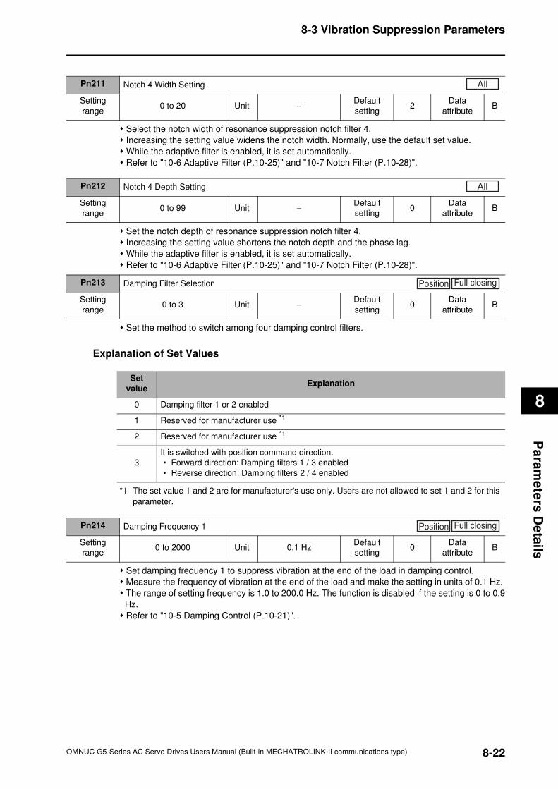
8-3 Vibration Suppression Parameters
8
Pa
ram
ete
rs D
eta
ils
Select the notch width of resonance suppression notch filter 4.
Increasing the setting value widens the notch width. Normally, use the default set value.
While the adaptive filter is enabled, it is set automatically.
Refer to "10-6 Adaptive Filter (P.10-25)" and "10-7 Notch Filter (P.10-28)".
Set the notch depth of resonance suppression notch filter 4.
Increasing the setting value shortens the notch depth and the phase lag.
While the adaptive filter is enabled, it is set automatically.
Refer to "10-6 Adaptive Filter (P.10-25)" and "10-7 Notch Filter (P.10-28)".
Set the method to switch among four damping control filters.
Explanation of Set Values
*1 The set value 1 and 2 are for manufacturer's use only. Users are not allowed to set 1 and 2 for this
parameter.
Set damping frequency 1 to suppress vibration at the end of the load in damping control.
Measure the frequency of vibration at the end of the load and make the setting in units of 0.1 Hz.
The range of setting frequency is 1.0 to 200.0 Hz. The function is disabled if the setting is 0 to 0.9
Hz.
Refer to "10-5 Damping Control (P.10-21)".
Pn211 Notch 4 Width Setting
Setting
range0 to 20 Unit −
Default
setting2
Data
attributeB
All
Pn212 Notch 4 Depth Setting
Setting
range0 to 99 Unit −
Default
setting0
Data
attributeB
All
Pn213 Damping Filter Selection
Setting
range0 to 3 Unit −
Default
setting0
Data
attributeB
Position Full closing
Set
valueExplanation
0 Damping filter 1 or 2 enabled
1 Reserved for manufacturer use *1
2 Reserved for manufacturer use *1
3
It is switched with position command direction.
• Forward direction: Damping filters 1 / 3 enabled
• Reverse direction: Damping filters 2 / 4 enabled
Pn214 Damping Frequency 1
Setting
range0 to 2000 Unit 0.1 Hz
Default
setting0
Data
attributeB
Position Full closing
8-22OMNUC G5-Series AC Servo Drives Users Manual (Built-in MECHATROLINK-II communications type)
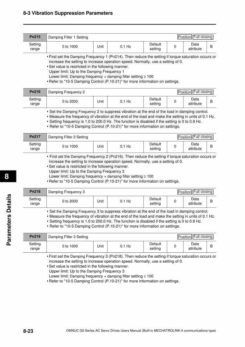
8-3 Vibration Suppression Parameters
8
Pa
ram
ete
rs D
eta
ils
First set the Damping Frequency 1 (Pn214). Then reduce the setting if torque saturation occurs or
increase the setting to increase operation speed. Normally, use a setting of 0.
Set value is restricted in the following manner.
Upper limit: Up to the Damping Frequency 1
Lower limit: Damping frequency + damping filter setting ≥ 100
Refer to "10-5 Damping Control (P.10-21)" for more information on settings.
Set the Damping Frequency 2 to suppress vibration at the end of the load in damping control.
Measure the frequency of vibration at the end of the load and make the setting in units of 0.1 Hz.
Setting frequency is 1.0 to 200.0 Hz. The function is disabled if the setting is 0 to 0.9 Hz.
Refer to "10-5 Damping Control (P.10-21)" for more information on settings.
First set the Damping Frequency 2 (Pn216). Then reduce the setting if torque saturation occurs or
increase the setting to increase operation speed. Normally, use a setting of 0.
Set value is restricted in the following manner.
Upper limit: Up to the Damping Frequency 2
Lower limit: Damping frequency + damping filter setting ≥ 100
Refer to "10-5 Damping Control (P.10-21)" for more information on settings.
Set the Damping Frequency 3 to suppress vibration at the end of the load in damping control.
Measure the frequency of vibration at the end of the load and make the setting in units of 0.1 Hz.
Setting frequency is 1.0 to 200.0 Hz. The function is disabled if the setting is 0 to 0.9 Hz.
Refer to "10-5 Damping Control (P.10-21)" for more information on settings.
First set the Damping Frequency 3 (Pn218). Then reduce the setting if torque saturation occurs or
increase the setting to increase operation speed. Normally, use a setting of 0.
Set value is restricted in the following manner.
Upper limit: Up to the Damping Frequency 3
Lower limit: Damping frequency + damping filter setting ≥ 100
Refer to "10-5 Damping Control (P.10-21)" for more information on settings.
Pn215 Damping Filter 1 Setting
Setting
range0 to 1000 Unit 0.1 Hz
Default
setting0
Data
attributeB
Position Full closing
Pn216 Damping Frequency 2
Setting
range0 to 2000 Unit 0.1 Hz
Default
setting0
Data
attributeB
Position Full closing
Pn217 Damping Filter 2 Setting
Setting
range0 to 1000 Unit 0.1 Hz
Default
setting0
Data
attributeB
Position Full closing
Pn218 Damping Frequency 3
Setting
range0 to 2000 Unit 0.1 Hz
Default
setting0
Data
attributeB
Position Full closing
Pn219 Damping Filter 3 Setting
Setting
range0 to 1000 Unit 0.1 Hz
Default
setting0
Data
attributeB
Position Full closing
8-23 OMNUC G5-Series AC Servo Drives Users Manual (Built-in MECHATROLINK-II communications type)
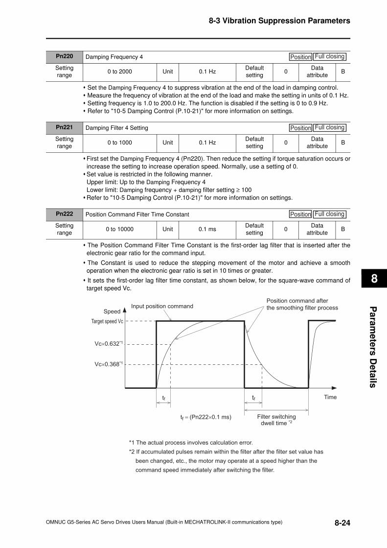
8-3 Vibration Suppression Parameters
8
Pa
ram
ete
rs D
eta
ils
Set the Damping Frequency 4 to suppress vibration at the end of the load in damping control.
Measure the frequency of vibration at the end of the load and make the setting in units of 0.1 Hz.
Setting frequency is 1.0 to 200.0 Hz. The function is disabled if the setting is 0 to 0.9 Hz.
Refer to "10-5 Damping Control (P.10-21)" for more information on settings.
First set the Damping Frequency 4 (Pn220). Then reduce the setting if torque saturation occurs or
increase the setting to increase operation speed. Normally, use a setting of 0.
Set value is restricted in the following manner.
Upper limit: Up to the Damping Frequency 4
Lower limit: Damping frequency + damping filter setting ≥ 100
Refer to "10-5 Damping Control (P.10-21)" for more information on settings.
The Position Command Filter Time Constant is the first-order lag filter that is inserted after the
electronic gear ratio for the command input.
The Constant is used to reduce the stepping movement of the motor and achieve a smooth
operation when the electronic gear ratio is set in 10 times or greater.
It sets the first-order lag filter time constant, as shown below, for the square-wave command of
target speed Vc.
Pn220 Damping Frequency 4
Setting
range0 to 2000 Unit 0.1 Hz
Default
setting0
Data
attributeB
Position Full closing
Pn221 Damping Filter 4 Setting
Setting
range0 to 1000 Unit 0.1 Hz
Default
setting0
Data
attributeB
Position Full closing
Pn222 Position Command Filter Time Constant
Setting
range0 to 10000 Unit 0.1 ms
Default
setting0
Data
attributeB
Position Full closing
tf = (Pn222×0.1 ms)
*1 The actual process involves calculation error.
*2 If accumulated pulses remain within the filter after the filter set value has
been changed, etc., the motor may operate at a speed higher than the
command speed immediately after switching the filter.
Input position command
tf
Position command after
the smoothing filter process
tf
Filter switchingdwell time *2
Time
Speed
Target speed Vc
Vc×0.632*1
Vc×0.368*1
8-24OMNUC G5-Series AC Servo Drives Users Manual (Built-in MECHATROLINK-II communications type)
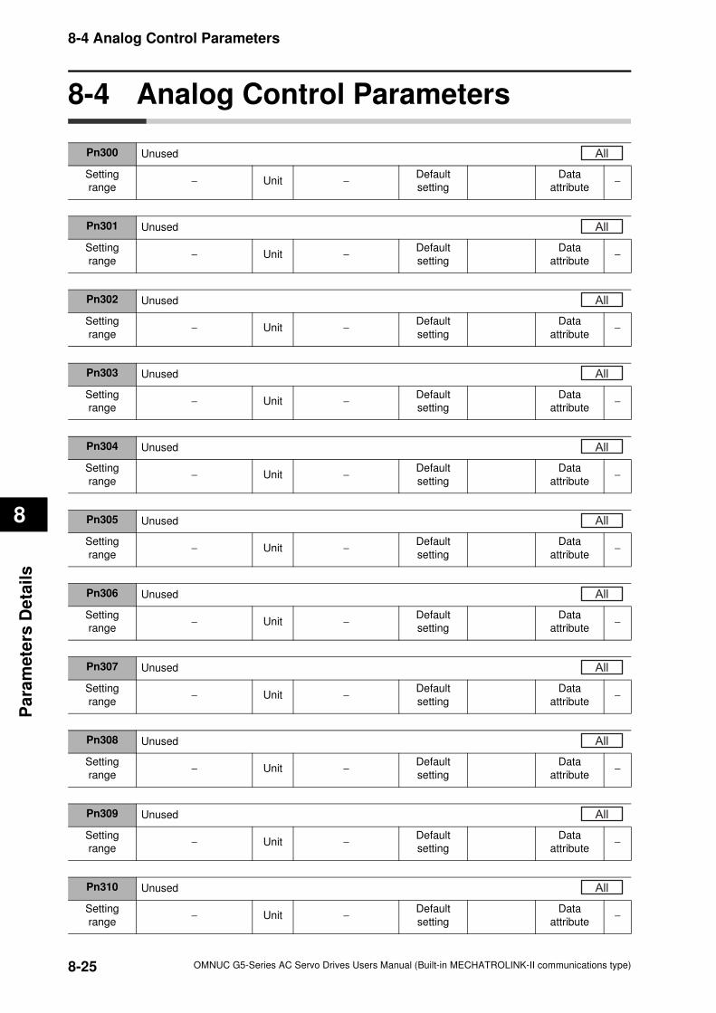
8-4 Analog Control Parameters
8
Pa
ram
ete
rs D
eta
ils
8-4 Analog Control Parameters
Pn300 Unused
Setting
range− Unit −
Default
setting
Data
attribute−
All
Pn301 Unused
Setting
range− Unit −
Default
setting
Data
attribute−
All
Pn302 Unused
Setting
range− Unit −
Default
setting
Data
attribute−
All
Pn303 Unused
Setting
range− Unit −
Default
setting
Data
attribute−
All
Pn304 Unused
Setting
range− Unit −
Default
setting
Data
attribute−
All
Pn305 Unused
Setting
range− Unit −
Default
setting
Data
attribute−
All
Pn306 Unused
Setting
range− Unit −
Default
setting
Data
attribute−
All
Pn307 Unused
Setting
range− Unit −
Default
setting
Data
attribute−
All
Pn308 Unused
Setting
range− Unit −
Default
setting
Data
attribute−
All
Pn309 Unused
Setting
range− Unit −
Default
setting
Data
attribute−
All
Pn310 Unused
Setting
range− Unit −
Default
setting
Data
attribute−
All
8-25 OMNUC G5-Series AC Servo Drives Users Manual (Built-in MECHATROLINK-II communications type)
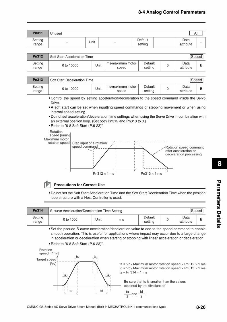
8-4 Analog Control Parameters
8
Pa
ram
ete
rs D
eta
ils
Control the speed by setting acceleration/deceleration to the speed command inside the Servo
Drive.
A soft start can be set when inputting speed commands of stepping movement or when using
internal speed setting.
Do not set acceleration/deceleration time settings when using the Servo Drive in combination with
an external position loop. (Set both Pn312 and Pn313 to 0.)
Refer to "6-8 Soft Start (P.6-23)".
Precautions for Correct Use
Do not set the Soft Start Acceleration Time and the Soft Start Deceleration Time when the position
loop structure with a Host Controller is used.
Set the pseudo-S-curve acceleration/deceleration value to add to the speed command to enable
smooth operation. This is useful for applications where impact may occur due to a large change
in acceleration or deceleration when starting or stopping with linear acceleration or deceleration.
Refer to "6-8 Soft Start (P.6-23)".
Pn311 Unused
Setting
range− Unit −
Default
setting
Data
attribute−
All
Pn312 Soft Start Acceleration Time
Setting
range0 to 10000 Unit
ms/maximum motor
speed
Default
setting0
Data
attributeB
Speed
Pn313 Soft Start Deceleration Time
Setting
range0 to 10000 Unit
ms/maximum motor
speed
Default
setting0
Data
attributeB
Speed
Rotation speed [r/min]
Maximum motor rotation speed Step input of a rotation
speed command Rotation speed command after acceleration or deceleration processing
Pn312 × 1 ms Pn313 × 1 ms
Pn314 S-curve Acceleration/Deceleration Time Setting
Setting
range0 to 1000 Unit ms
Default
setting0
Data
attributeB
Speed
ta td
ts ts
tsts
Rotation speed [r/min]
Target speed
(Vc) ta = Vc / Maximum motor rotation speed × Pn312 × 1 ms
td = Vc / Maximum motor rotation speed × Pn313 × 1 ms
ts = Pn314 × 1 ms
Be sure that ts is smaller than the values
obtained by the divisions of
and .2
ta
2
td
8-26OMNUC G5-Series AC Servo Drives Users Manual (Built-in MECHATROLINK-II communications type)
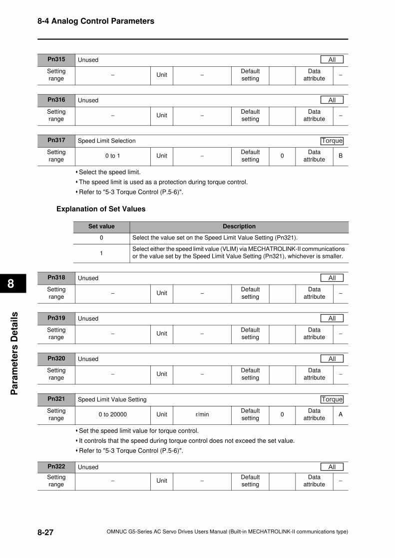
8-4 Analog Control Parameters
8
Pa
ram
ete
rs D
eta
ils
Select the speed limit.
The speed limit is used as a protection during torque control.
Refer to "5-3 Torque Control (P.5-6)".
Explanation of Set Values
Set the speed limit value for torque control.
It controls that the speed during torque control does not exceed the set value.
Refer to "5-3 Torque Control (P.5-6)".
Pn315 Unused
Setting
range− Unit −
Default
setting
Data
attribute−
All
Pn316 Unused
Setting
range− Unit −
Default
setting
Data
attribute−
All
Pn317 Speed Limit Selection
Setting
range0 to 1 Unit −
Default
setting0
Data
attributeB
Torque
Set value Description
0 Select the value set on the Speed Limit Value Setting (Pn321).
1Select either the speed limit value (VLIM) via MECHATROLINK-II communications
or the value set by the Speed Limit Value Setting (Pn321), whichever is smaller.
Pn318 Unused
Setting
range− Unit −
Default
setting
Data
attribute−
All
Pn319 Unused
Setting
range− Unit −
Default
setting
Data
attribute−
All
Pn320 Unused
Setting
range− Unit −
Default
setting
Data
attribute−
All
Pn321 Speed Limit Value Setting
Setting
range0 to 20000 Unit r/min
Default
setting0
Data
attributeA
Torque
Pn322 Unused
Setting
range− Unit −
Default
setting
Data
attribute−
All
8-27 OMNUC G5-Series AC Servo Drives Users Manual (Built-in MECHATROLINK-II communications type)
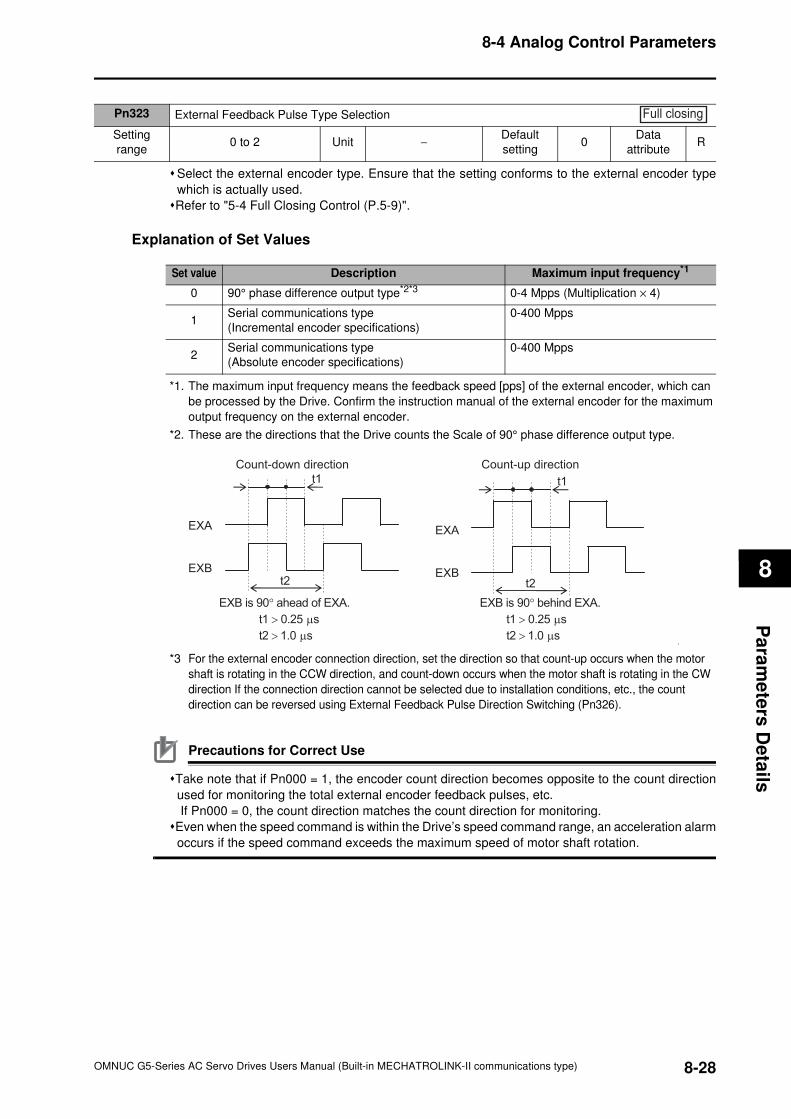
8-4 Analog Control Parameters
8
Pa
ram
ete
rs D
eta
ils
Select the external encoder type. Ensure that the setting conforms to the external encoder type
which is actually used.
Refer to "5-4 Full Closing Control (P.5-9)".
Explanation of Set Values
*1. The maximum input frequency means the feedback speed [pps] of the external encoder, which can
be processed by the Drive. Confirm the instruction manual of the external encoder for the maximum
output frequency on the external encoder.
*2. These are the directions that the Drive counts the Scale of 90° phase difference output type.
*3 For the external encoder connection direction, set the direction so that count-up occurs when the motor
shaft is rotating in the CCW direction, and count-down occurs when the motor shaft is rotating in the CW
direction If the connection direction cannot be selected due to installation conditions, etc., the count
direction can be reversed using External Feedback Pulse Direction Switching (Pn326).
Precautions for Correct Use
Take note that if Pn000 = 1, the encoder count direction becomes opposite to the count direction
used for monitoring the total external encoder feedback pulses, etc.
If Pn000 = 0, the count direction matches the count direction for monitoring.
Even when the speed command is within the Drive’s speed command range, an acceleration alarm
occurs if the speed command exceeds the maximum speed of motor shaft rotation.
Pn323 External Feedback Pulse Type Selection
Setting
range0 to 2 Unit −
Default
setting0
Data
attributeR
Full closing
Set value Description Maximum input frequency*1
0 90° phase difference output type*2*3 0-4 Mpps (Multiplication × 4)
1Serial communications type
(Incremental encoder specifications)
0-400 Mpps
2Serial communications type
(Absolute encoder specifications)
0-400 Mpps
Count-down direction Count-up direction
EXB is 90° ahead of EXA.
t1 > 0.25 µs
t2 > 1.0 µs
EXB is 90° behind EXA.
t1 > 0.25 µs
t2 > 1.0 µs
t1
t2
t1
t2
EXA
EXB
EXA
EXB
8-28OMNUC G5-Series AC Servo Drives Users Manual (Built-in MECHATROLINK-II communications type)
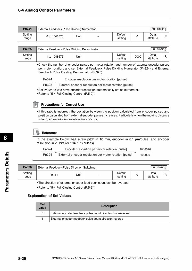
8-4 Analog Control Parameters
8
Pa
ram
ete
rs D
eta
ils
Check the number of encoder pulses per motor rotation and number of external encoder pulses
per motor rotation, and set External Feedback Pulse Dividing Numerator (Pn324) and External
Feedback Pulse Dividing Denominator (Pn325).
Set Pn324 to 0 to have encoder resolution automatically set as numerator.
Refer to "5-4 Full Closing Control (P.5-9)".
Precautions for Correct Use
If this ratio is incorrect, the deviation between the position calculated from encoder pulses and
position calculated from external encoder pulses increases. Particularly when the moving distance
is long, an excessive deviation error occurs.
Reference
In the example below: ball screw pitch in 10 mm, encoder in 0.1 µm/pulse, and encoder
resolution in 20 bits (or 1048576 pulses)
The direction of external encoder feed back count can be reversed.
Refer to "5-4 Full Closing Control (P.5-9)".
Explanation of Set Values
Pn324 External Feedback Pulse Dividing Numerator
Setting
range0 to 1048576 Unit −
Default
setting0
Data
attributeR
Full closing
Pn325 External Feedback Pulse Dividing Denominator
Setting
range1 to 1048576 Unit −
Default
setting10000
Data
attributeR
Full closing
=
Encoder resolution per motor rotation [pulse]
External encoder resolution per motor rotation [pulse]
Pn324
Pn325
=Encoder resolution per motor rotation [pulse]
External encoder resolution per motor rotation [pulse]
Pn324
Pn325 100000
1048576=
Pn326 External Feedback Pulse Direction Switching
Setting
range0 to 1 Unit −
Default
setting0
Data
attributeR
Full closing
Set
valueDescription
0 External encoder feedback pulse count direction non-reverse
1 External encoder feedback pulse count direction reverse
8-29 OMNUC G5-Series AC Servo Drives Users Manual (Built-in MECHATROLINK-II communications type)
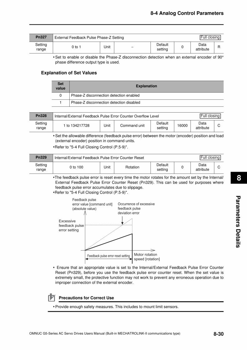
8-4 Analog Control Parameters
8
Pa
ram
ete
rs D
eta
ils
Set to enable or disable the Phase-Z disconnection detection when an external encoder of 90°
phase difference output type is used.
Explanation of Set Values
Set the allowable difference (feedback pulse error) between the motor (encoder) position and load
(external encoder) position in command units.
Refer to "5-4 Full Closing Control (P.5-9)".
The feedback pulse error is reset every time the motor rotates for the amount set by the Internal/
External Feedback Pulse Error Counter Reset (Pn329). This can be used for purposes where
feedback pulse error accumulates due to slippage.
Refer to "5-4 Full Closing Control (P.5-9)".
Ensure that an appropriate value is set to the Internal/External Feedback Pulse Error Counter
Reset (Pn329), before you use the feedback pulse error counter reset. When the set value is
extremely small, the protective function may not work to prevent any erroneous operation due to
improper connection of the external encoder.
Precautions for Correct Use
Provide enough safety measures. This includes to mount limit sensors.
Pn327 External Feedback Pulse Phase-Z Setting
Setting
range0 to 1 Unit −
Default
setting0
Data
attributeR
Full closing
Set
valueExplanation
0 Phase-Z disconnection detection enabled
1 Phase-Z disconnection detection disabled
Pn328 Internal/External Feedback Pulse Error Counter Overflow Level
Setting
range1 to 134217728 Unit Command unit
Default
setting16000
Data
attributeC
Full closing
Pn329 Internal/External Feedback Pulse Error Counter Reset
Setting
range0 to 100 Unit Rotation
Default
setting0
Data
attributeC
Full closing
Feedback pulse
error value [command unit]
(absolute value)
Excessive
feedback pulse
error setting
Occurrence of excessive
feedback pulse
deviation error
Motor rotation
speed [rotation]Feedback pulse error reset setting
8-30OMNUC G5-Series AC Servo Drives Users Manual (Built-in MECHATROLINK-II communications type)
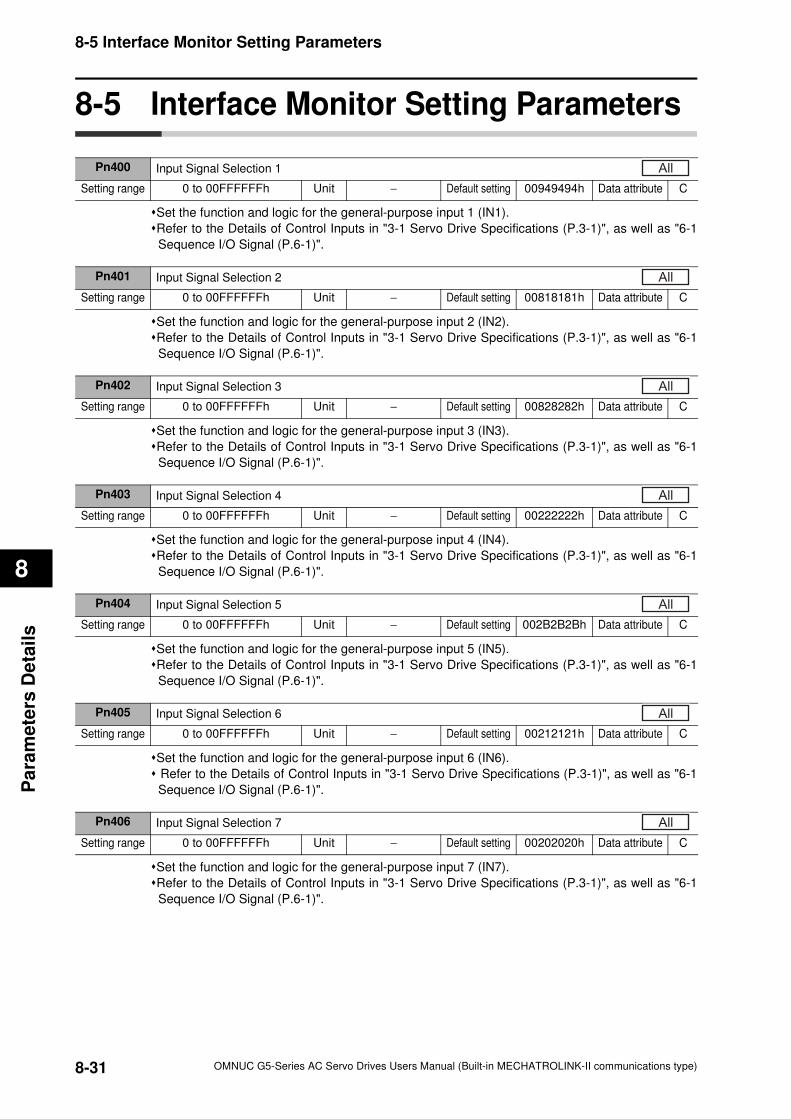
8-5 Interface Monitor Setting Parameters
8
Pa
ram
ete
rs D
eta
ils
8-5 Interface Monitor Setting Parameters
Set the function and logic for the general-purpose input 1 (IN1).
Refer to the Details of Control Inputs in "3-1 Servo Drive Specifications (P.3-1)", as well as "6-1
Sequence I/O Signal (P.6-1)".
Set the function and logic for the general-purpose input 2 (IN2).
Refer to the Details of Control Inputs in "3-1 Servo Drive Specifications (P.3-1)", as well as "6-1
Sequence I/O Signal (P.6-1)".
Set the function and logic for the general-purpose input 3 (IN3).
Refer to the Details of Control Inputs in "3-1 Servo Drive Specifications (P.3-1)", as well as "6-1
Sequence I/O Signal (P.6-1)".
Set the function and logic for the general-purpose input 4 (IN4).
Refer to the Details of Control Inputs in "3-1 Servo Drive Specifications (P.3-1)", as well as "6-1
Sequence I/O Signal (P.6-1)".
Set the function and logic for the general-purpose input 5 (IN5).
Refer to the Details of Control Inputs in "3-1 Servo Drive Specifications (P.3-1)", as well as "6-1
Sequence I/O Signal (P.6-1)".
Set the function and logic for the general-purpose input 6 (IN6).
Refer to the Details of Control Inputs in "3-1 Servo Drive Specifications (P.3-1)", as well as "6-1
Sequence I/O Signal (P.6-1)".
Set the function and logic for the general-purpose input 7 (IN7).
Refer to the Details of Control Inputs in "3-1 Servo Drive Specifications (P.3-1)", as well as "6-1
Sequence I/O Signal (P.6-1)".
Pn400 Input Signal Selection 1
Setting range 0 to 00FFFFFFh Unit − Default setting 00949494h Data attribute C
All
Pn401 Input Signal Selection 2
Setting range 0 to 00FFFFFFh Unit − Default setting 00818181h Data attribute C
All
Pn402 Input Signal Selection 3
Setting range 0 to 00FFFFFFh Unit − Default setting 00828282h Data attribute C
All
Pn403 Input Signal Selection 4
Setting range 0 to 00FFFFFFh Unit − Default setting 00222222h Data attribute C
All
Pn404 Input Signal Selection 5
Setting range 0 to 00FFFFFFh Unit − Default setting 002B2B2Bh Data attribute C
All
Pn405 Input Signal Selection 6
Setting range 0 to 00FFFFFFh Unit − Default setting 00212121h Data attribute C
All
Pn406 Input Signal Selection 7
Setting range 0 to 00FFFFFFh Unit − Default setting 00202020h Data attribute C
All
8-31 OMNUC G5-Series AC Servo Drives Users Manual (Built-in MECHATROLINK-II communications type)
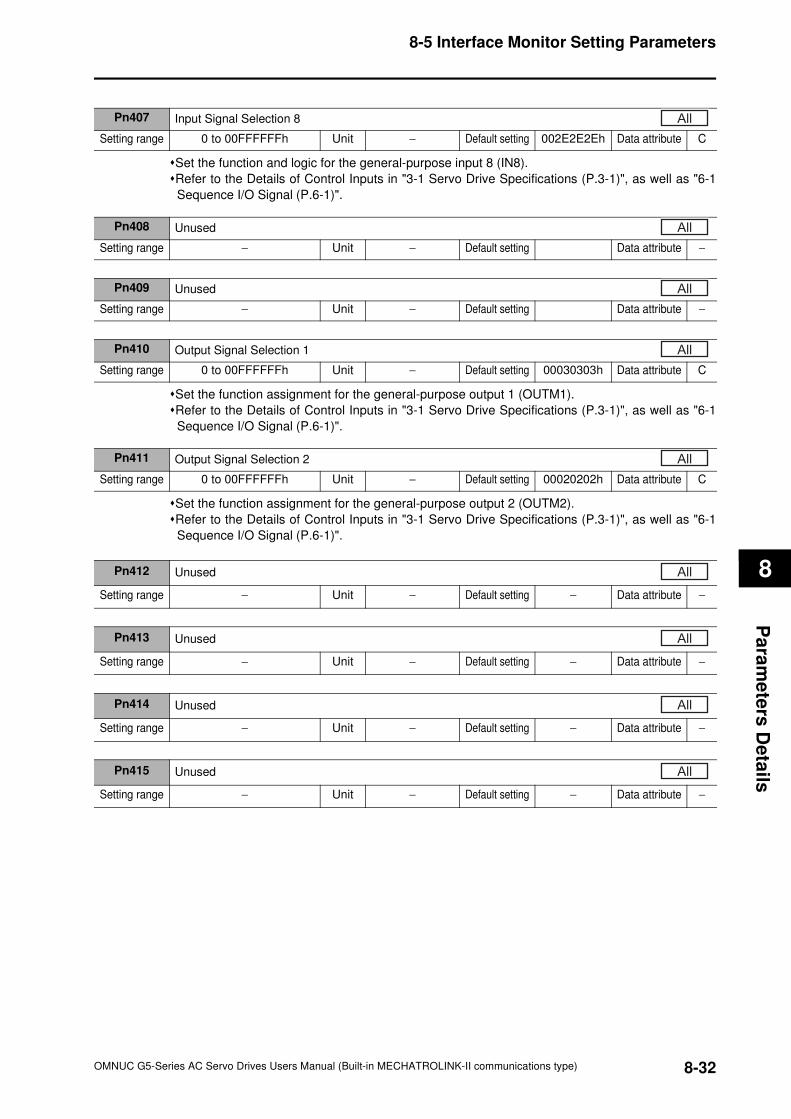
8-5 Interface Monitor Setting Parameters
8
Pa
ram
ete
rs D
eta
ils
Set the function and logic for the general-purpose input 8 (IN8).
Refer to the Details of Control Inputs in "3-1 Servo Drive Specifications (P.3-1)", as well as "6-1
Sequence I/O Signal (P.6-1)".
Set the function assignment for the general-purpose output 1 (OUTM1).
Refer to the Details of Control Inputs in "3-1 Servo Drive Specifications (P.3-1)", as well as "6-1
Sequence I/O Signal (P.6-1)".
Set the function assignment for the general-purpose output 2 (OUTM2).
Refer to the Details of Control Inputs in "3-1 Servo Drive Specifications (P.3-1)", as well as "6-1
Sequence I/O Signal (P.6-1)".
Pn407 Input Signal Selection 8
Setting range 0 to 00FFFFFFh Unit − Default setting 002E2E2Eh Data attribute C
All
Pn408 Unused
Setting range − Unit − Default setting Data attribute −
All
Pn409 Unused
Setting range − Unit − Default setting Data attribute −
All
Pn410 Output Signal Selection 1
Setting range 0 to 00FFFFFFh Unit − Default setting 00030303h Data attribute C
All
Pn411 Output Signal Selection 2
Setting range 0 to 00FFFFFFh Unit − Default setting 00020202h Data attribute C
All
Pn412 Unused
Setting range − Unit − Default setting − Data attribute −
All
Pn413 Unused
Setting range − Unit − Default setting − Data attribute −
All
Pn414 Unused
Setting range − Unit − Default setting − Data attribute −
All
Pn415 Unused
Setting range − Unit − Default setting − Data attribute −
All
8-32OMNUC G5-Series AC Servo Drives Users Manual (Built-in MECHATROLINK-II communications type)
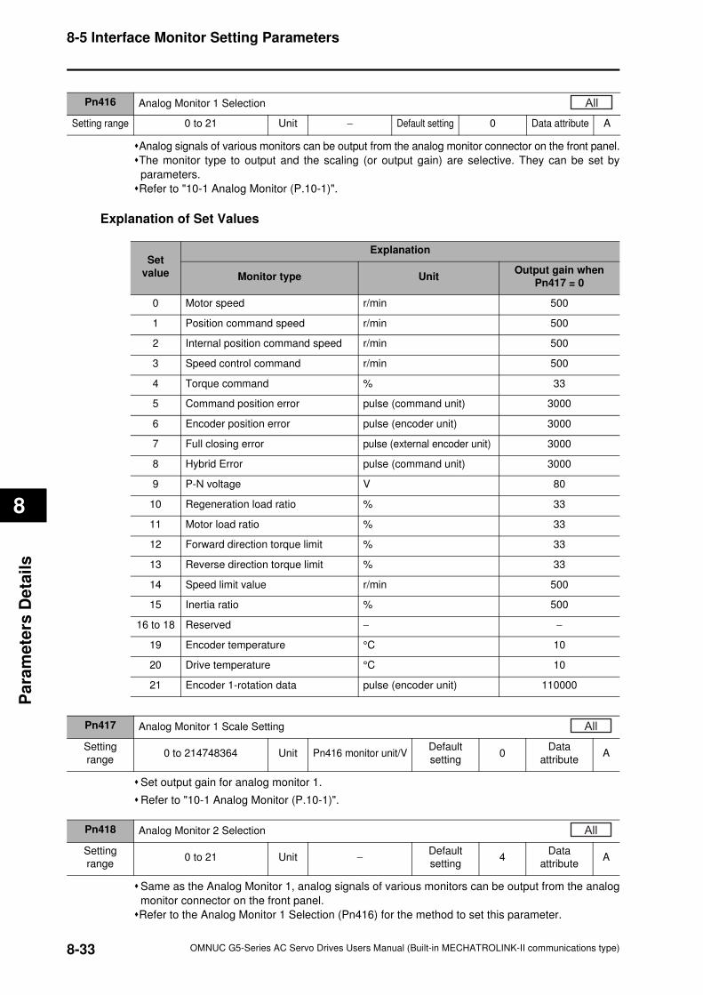
8-5 Interface Monitor Setting Parameters
8
Pa
ram
ete
rs D
eta
ils
Analog signals of various monitors can be output from the analog monitor connector on the front panel.
The monitor type to output and the scaling (or output gain) are selective. They can be set by
parameters.
Refer to "10-1 Analog Monitor (P.10-1)".
Explanation of Set Values
Set output gain for analog monitor 1.
Refer to "10-1 Analog Monitor (P.10-1)".
Same as the Analog Monitor 1, analog signals of various monitors can be output from the analog
monitor connector on the front panel.
Refer to the Analog Monitor 1 Selection (Pn416) for the method to set this parameter.
Pn416 Analog Monitor 1 Selection
Setting range 0 to 21 Unit − Default setting 0 Data attribute A
All
Set
value
Explanation
Monitor type UnitOutput gain when
Pn417 = 0
0 Motor speed r/min 500
1 Position command speed r/min 500
2 Internal position command speed r/min 500
3 Speed control command r/min 500
4 Torque command % 33
5 Command position error pulse (command unit) 3000
6 Encoder position error pulse (encoder unit) 3000
7 Full closing error pulse (external encoder unit) 3000
8 Hybrid Error pulse (command unit) 3000
9 P-N voltage V 80
10 Regeneration load ratio % 33
11 Motor load ratio % 33
12 Forward direction torque limit % 33
13 Reverse direction torque limit % 33
14 Speed limit value r/min 500
15 Inertia ratio % 500
16 to 18 Reserved − −
19 Encoder temperature °C 10
20 Drive temperature °C 10
21 Encoder 1-rotation data pulse (encoder unit) 110000
Pn417 Analog Monitor 1 Scale Setting
Setting
range0 to 214748364 Unit Pn416 monitor unit/V
Default
setting0
Data
attributeA
All
Pn418 Analog Monitor 2 Selection
Setting
range0 to 21 Unit −
Default
setting4
Data
attributeA
All
8-33 OMNUC G5-Series AC Servo Drives Users Manual (Built-in MECHATROLINK-II communications type)
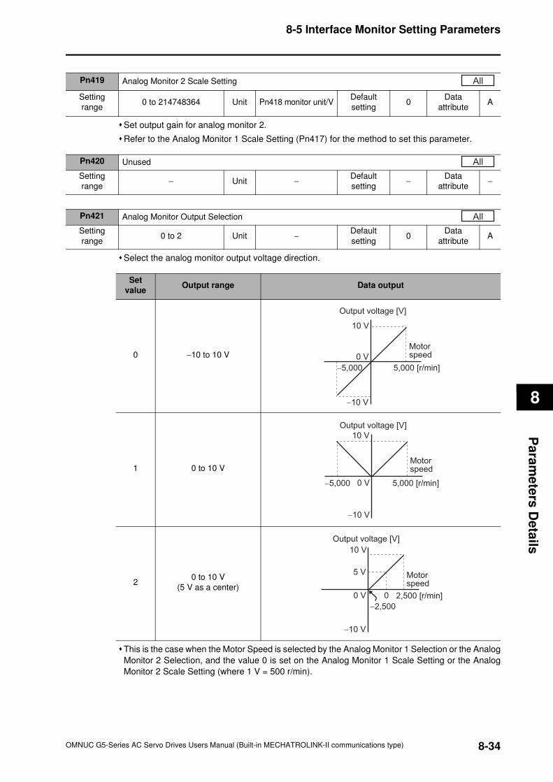
8-5 Interface Monitor Setting Parameters
8
Pa
ram
ete
rs D
eta
ils
Set output gain for analog monitor 2.
Refer to the Analog Monitor 1 Scale Setting (Pn417) for the method to set this parameter.
Select the analog monitor output voltage direction.
This is the case when the Motor Speed is selected by the Analog Monitor 1 Selection or the Analog
Monitor 2 Selection, and the value 0 is set on the Analog Monitor 1 Scale Setting or the Analog
Monitor 2 Scale Setting (where 1 V = 500 r/min).
Pn419 Analog Monitor 2 Scale Setting
Setting
range0 to 214748364 Unit Pn418 monitor unit/V
Default
setting0
Data
attributeA
All
Pn420 Unused
Setting
range− Unit −
Default
setting−
Data
attribute−
All
Pn421 Analog Monitor Output Selection
Setting
range0 to 2 Unit −
Default
setting0
Data
attributeA
All
Set
valueOutput range Data output
0 −10 to 10 V
1 0 to 10 V
20 to 10 V
(5 V as a center)
10 V
−10 V
0 V
−5,000 5,000 [r/min]
Motorspeed
Output voltage [V]
10 V
−10 V
0 V−5,000 5,000 [r/min]
Motorspeed
Output voltage [V]
10 V
5 V
−10 V
0 V 0
−2,500
2,500 [r/min]
Motorspeed
Output voltage [V]
8-34OMNUC G5-Series AC Servo Drives Users Manual (Built-in MECHATROLINK-II communications type)
8-5 Interface Monitor Setting Parameters
8
Pa
ram
ete
rs D
eta
ils
Pn422 Unused
Setting
range− Unit −
Default
setting−
Data
attribute−
All
Pn423 Unused
Setting
range− Unit −
Default
setting−
Data
attribute−
All
Pn424 Unused
Setting
range− Unit −
Default
setting−
Data
attribute−
All
Pn425 Unused
Setting
range− Unit −
Default
setting−
Data
attribute−
All
Pn426 Unused
Setting
range− Unit −
Default
setting−
Data
attribute−
All
Pn427 Unused
Setting
range− Unit −
Default
setting−
Data
attribute−
All
Pn428 Unused
Setting
range− Unit −
Default
setting−
Data
attribute−
All
Pn429 Unused
Setting
range− Unit −
Default
setting−
Data
attribute−
All
Pn430 Unused
Setting
range− Unit −
Default
setting−
Data
attribute−
All
8-35 OMNUC G5-Series AC Servo Drives Users Manual (Built-in MECHATROLINK-II communications type)
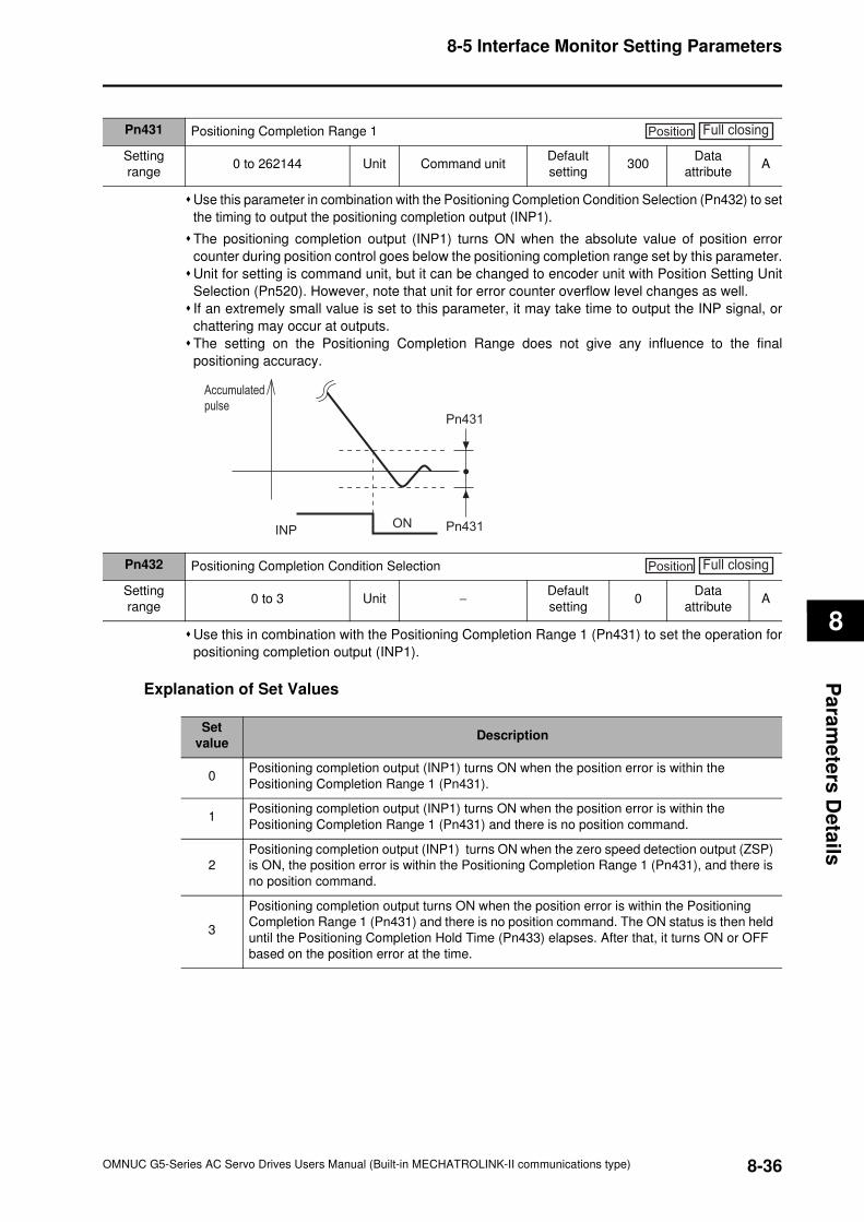
8-5 Interface Monitor Setting Parameters
8
Pa
ram
ete
rs D
eta
ils
Use this parameter in combination with the Positioning Completion Condition Selection (Pn432) to set
the timing to output the positioning completion output (INP1).
The positioning completion output (INP1) turns ON when the absolute value of position error
counter during position control goes below the positioning completion range set by this parameter.
Unit for setting is command unit, but it can be changed to encoder unit with Position Setting Unit
Selection (Pn520). However, note that unit for error counter overflow level changes as well.
If an extremely small value is set to this parameter, it may take time to output the INP signal, or
chattering may occur at outputs.
The setting on the Positioning Completion Range does not give any influence to the final
positioning accuracy.
Use this in combination with the Positioning Completion Range 1 (Pn431) to set the operation for
positioning completion output (INP1).
Explanation of Set Values
Pn431 Positioning Completion Range 1
Setting
range0 to 262144 Unit Command unit
Default
setting300
Data
attributeA
Position Full closing
INP
Accumulated
pulse
ON Pn431
Pn431
Pn432 Positioning Completion Condition Selection
Setting
range0 to 3 Unit −
Default
setting0
Data
attributeA
Position Full closing
Set
valueDescription
0Positioning completion output (INP1) turns ON when the position error is within the
Positioning Completion Range 1 (Pn431).
1Positioning completion output (INP1) turns ON when the position error is within the
Positioning Completion Range 1 (Pn431) and there is no position command.
2
Positioning completion output (INP1) turns ON when the zero speed detection output (ZSP)
is ON, the position error is within the Positioning Completion Range 1 (Pn431), and there is
no position command.
3
Positioning completion output turns ON when the position error is within the Positioning
Completion Range 1 (Pn431) and there is no position command. The ON status is then held
until the Positioning Completion Hold Time (Pn433) elapses. After that, it turns ON or OFF
based on the position error at the time.
8-36OMNUC G5-Series AC Servo Drives Users Manual (Built-in MECHATROLINK-II communications type)
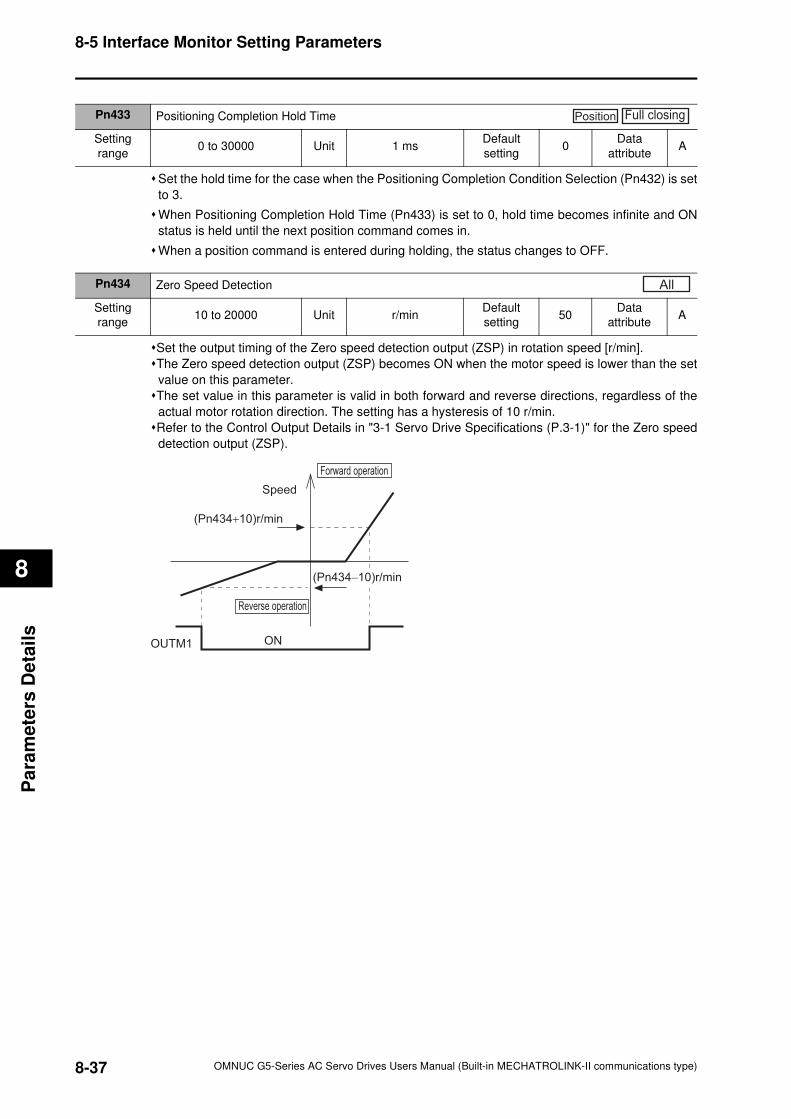
8-5 Interface Monitor Setting Parameters
8
Pa
ram
ete
rs D
eta
ils
Set the hold time for the case when the Positioning Completion Condition Selection (Pn432) is set
to 3.
When Positioning Completion Hold Time (Pn433) is set to 0, hold time becomes infinite and ON
status is held until the next position command comes in.
When a position command is entered during holding, the status changes to OFF.
Set the output timing of the Zero speed detection output (ZSP) in rotation speed [r/min].
The Zero speed detection output (ZSP) becomes ON when the motor speed is lower than the set
value on this parameter.
The set value in this parameter is valid in both forward and reverse directions, regardless of the
actual motor rotation direction. The setting has a hysteresis of 10 r/min.
Refer to the Control Output Details in "3-1 Servo Drive Specifications (P.3-1)" for the Zero speed
detection output (ZSP).
Pn433 Positioning Completion Hold Time
Setting
range0 to 30000 Unit 1 ms
Default
setting0
Data
attributeA
Position Full closing
Pn434 Zero Speed Detection
Setting
range10 to 20000 Unit r/min
Default
setting50
Data
attributeA
All
Speed
Reverse operation
OUTM1 ON
(Pn434+10)r/min
Forward operation
(Pn434−10)r/min
8-37 OMNUC G5-Series AC Servo Drives Users Manual (Built-in MECHATROLINK-II communications type)
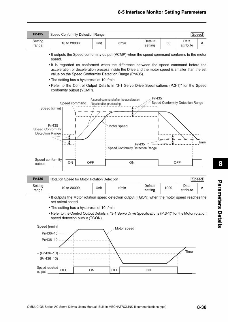
8-5 Interface Monitor Setting Parameters
8
Pa
ram
ete
rs D
eta
ils
It outputs the Speed conformity output (VCMP) when the speed command conforms to the motor
speed.
It is regarded as conformed when the difference between the speed command before the
acceleration or deceleration process inside the Drive and the motor speed is smaller than the set
value on the Speed Conformity Detection Range (Pn435).
The setting has a hysteresis of 10 r/min.
Refer to the Control Output Details in "3-1 Servo Drive Specifications (P.3-1)" for the Speed
conformity output (VCMP).
It outputs the Motor rotation speed detection output (TGON) when the motor speed reaches the
set arrival speed.
The setting has a hysteresis of 10 r/min.
Refer to the Control Output Details in "3-1 Servo Drive Specifications (P.3-1)" for the Motor rotation
speed detection output (TGON).
Pn435 Speed Conformity Detection Range
Setting
range10 to 20000 Unit r/min
Default
setting50
Data
attributeA
Speed
Speed [r/min]
A speed command after the acceleration
/deceleration processingSpeed command
Motor speedPn435
ON ONOFF OFF
Pn435
Speed Conformity
Detection Range
Pn435Speed Conformity Detection Range
Speed Conformity Detection Range
Time
Speed conformity
output
Pn436 Rotation Speed for Motor Rotation Detection
Setting
range10 to 20000 Unit r/min
Default
setting1000
Data
attributeA
Speed
Speed [r/min]Motor speed
Time
Pn436+10
Speed reached
output
Pn436−10
− (Pn436−10)
− (Pn436+10)
OFF OFFON ON
8-38OMNUC G5-Series AC Servo Drives Users Manual (Built-in MECHATROLINK-II communications type)
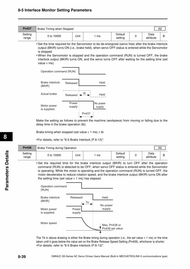
8-5 Interface Monitor Setting Parameters
8
Pa
ram
ete
rs D
eta
ils
Set the time required for the Servomotor to be de-energized (servo free) after the brake interlock
output (BKIR) turns ON (i.e., brake held), when servo OFF status is entered while the Servomotor
is stopped.
When the Servomotor is stopped and the operation command (RUN) is turned OFF, the brake
interlock output (BKIR) turns ON, and the servo turns OFF after waiting for the setting time (set
value × ms).
Make the setting as follows to prevent the machine (workpiece) from moving or falling due to the
delay time in the brake operation (tb).
Brake timing when stopped (set value × 1 ms) ≥ tb
For details, refer to "6-5 Brake Interlock (P.6-13)".
Set the required time for the brake interlock output (BKIR) to turn OFF after the operation
command (RUN) is detected to be OFF, when servo OFF status is entered while the Servomotor
is operating. While the motor is operating and the operation command (RUN) is turned OFF, the
motor decelerates to reduce rotation speed, and the brake interlock output (BKIR) turns ON after
the setting time (set value × 1 ms) has elapsed.
The TB in above drawing is either the Brake timing during operation (i.e., the set value × 1 ms) or the time
taken until it goes below the value set on the Brake Release Speed Setting (Pn439), whichever is shorter.
For details, refer to "6-5 Brake Interlock (P.6-13)".
Pn437 Brake Timing when Stopped
Setting
range0 to 10000 Unit 1 ms
Default
setting0
Data
attributeB
All
Operation command (RUN)
Brake interlock
(BKIR)
Actual brake
Motor power
is supplied.
Released Held
Released
Power
supply
Held
No power
supply
Pn437
tb
Pn438 Brake Timing during Operation
Setting
range0 to 10000 Unit 1 ms
Default
setting0
Data
attributeB
All
TB
Operation command
(RUN)
Brake interlock
(BKIR)
Motor speed
Released Held
Motor power
is supplied.
Power
supply
No power
supply
Max. Pn438 or
Pn439 set value
8-39 OMNUC G5-Series AC Servo Drives Users Manual (Built-in MECHATROLINK-II communications type)
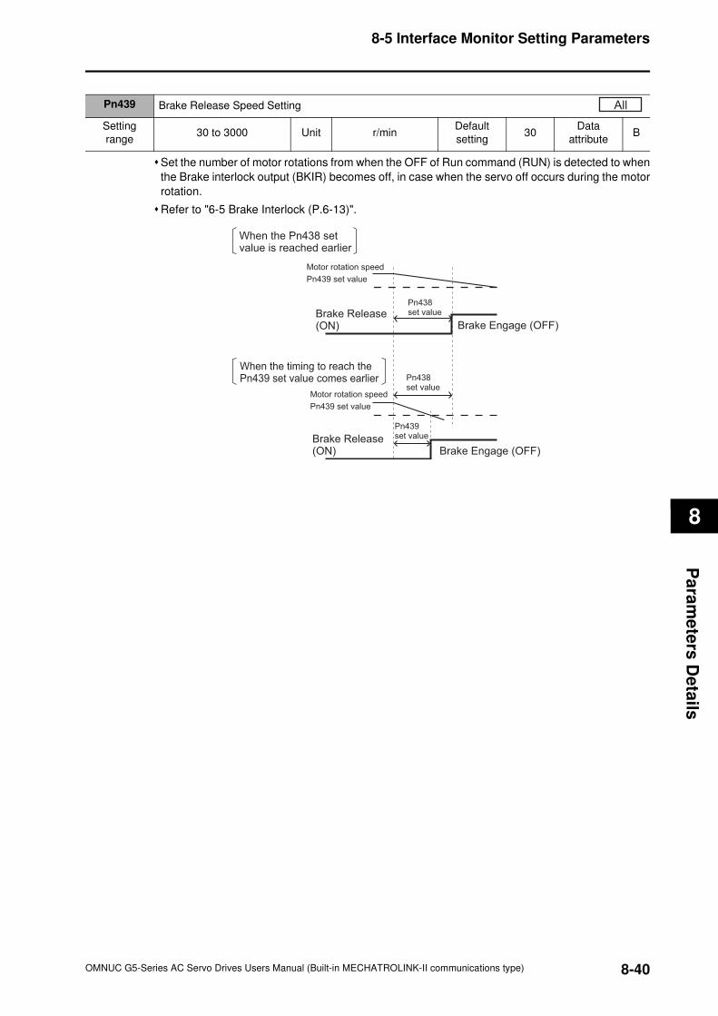
8-5 Interface Monitor Setting Parameters
8
Pa
ram
ete
rs D
eta
ils
Set the number of motor rotations from when the OFF of Run command (RUN) is detected to when
the Brake interlock output (BKIR) becomes off, in case when the servo off occurs during the motor
rotation.
Refer to "6-5 Brake Interlock (P.6-13)".
Pn439 Brake Release Speed Setting
Setting
range30 to 3000 Unit r/min
Default
setting30
Data
attributeB
All
Brake Release (ON)
Brake Release (ON) Brake Engage (OFF)
Brake Engage (OFF)
Motor rotation speed
Pn439 set value
Pn438 set value
Pn438 set value
Motor rotation speed
Pn439 set value
When the Pn438 set value is reached earlier
When the timing to reach the Pn439 set value comes earlier
Pn439 set value
8-40OMNUC G5-Series AC Servo Drives Users Manual (Built-in MECHATROLINK-II communications type)
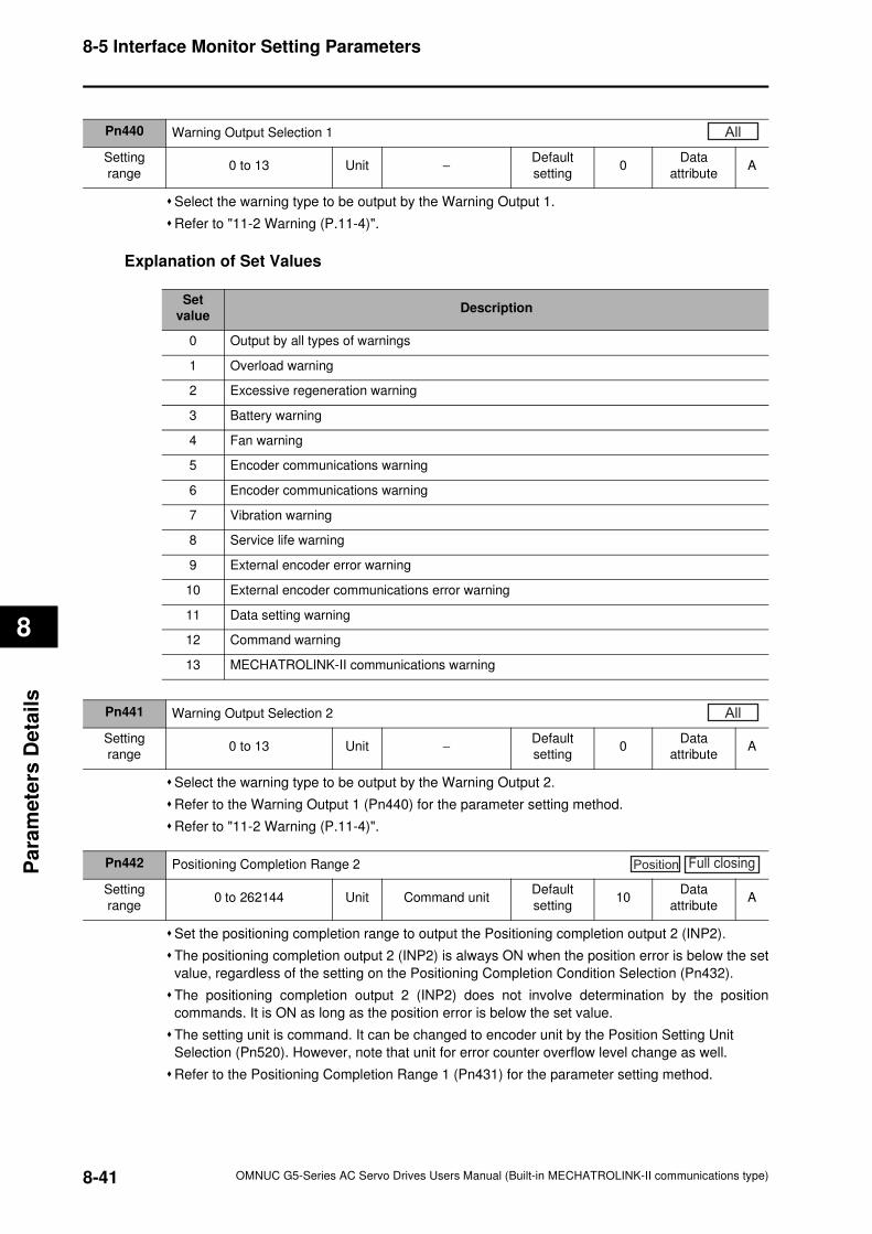
8-5 Interface Monitor Setting Parameters
8
Pa
ram
ete
rs D
eta
ils
Select the warning type to be output by the Warning Output 1.
Refer to "11-2 Warning (P.11-4)".
Explanation of Set Values
Select the warning type to be output by the Warning Output 2.
Refer to the Warning Output 1 (Pn440) for the parameter setting method.
Refer to "11-2 Warning (P.11-4)".
Set the positioning completion range to output the Positioning completion output 2 (INP2).
The positioning completion output 2 (INP2) is always ON when the position error is below the set
value, regardless of the setting on the Positioning Completion Condition Selection (Pn432).
The positioning completion output 2 (INP2) does not involve determination by the position
commands. It is ON as long as the position error is below the set value.
The setting unit is command. It can be changed to encoder unit by the Position Setting Unit
Selection (Pn520). However, note that unit for error counter overflow level change as well.
Refer to the Positioning Completion Range 1 (Pn431) for the parameter setting method.
Pn440 Warning Output Selection 1
Setting
range0 to 13 Unit −
Default
setting0
Data
attributeA
All
Set
valueDescription
0 Output by all types of warnings
1 Overload warning
2 Excessive regeneration warning
3 Battery warning
4 Fan warning
5 Encoder communications warning
6 Encoder communications warning
7 Vibration warning
8 Service life warning
9 External encoder error warning
10 External encoder communications error warning
11 Data setting warning
12 Command warning
13 MECHATROLINK-II communications warning
Pn441 Warning Output Selection 2
Setting
range0 to 13 Unit −
Default
setting0
Data
attributeA
All
Pn442 Positioning Completion Range 2
Setting
range0 to 262144 Unit Command unit
Default
setting10
Data
attributeA
Position Full closing
8-41 OMNUC G5-Series AC Servo Drives Users Manual (Built-in MECHATROLINK-II communications type)
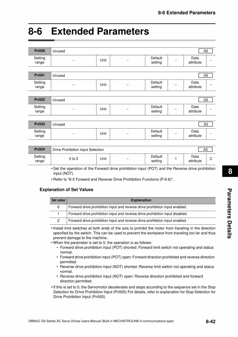
8-6 Extended Parameters
8
Pa
ram
ete
rs D
eta
ils
8-6 Extended Parameters
Set the operation of the Forward drive prohibition input (POT) and the Reverse drive prohibition
input (NOT).
Refer to "6-2 Forward and Reverse Drive Prohibition Functions (P.6-6)".
Explanation of Set Values
Install limit switches at both ends of the axis to prohibit the motor from traveling in the direction
specified by the switch. This can be used to prevent the workpiece from traveling too far and thus
prevent damage to the machine.
When the parameter is set to 0, the operation is as follows:
• Forward drive prohibition input (POT) shorted: Forward limit switch not operating and status
normal.
• Forward drive prohibition input (POT) open: Forward direction prohibited and reverse direction
permitted.
• Reverse drive prohibition input (NOT) shorted: Reverse limit switch not operating and status
normal.
• Reverse drive prohibition input (NOT) open: Reverse direction prohibited and forward
direction permitted.
If this is set to 0, the Servomotor decelerates and stops according to the sequence set in the Stop
Selection for Drive Prohibition Input (Pn505) For details, refer to explanation for Stop Selection for
Drive Prohibition Input (Pn505).
Pn500 Unused
Setting
range− Unit −
Default
setting−
Data
attribute−
All
Pn501 Unused
Setting
range− Unit −
Default
setting−
Data
attribute−
All
Pn502 Unused
Setting
range− Unit −
Default
setting−
Data
attribute−
All
Pn503 Unused
Setting
range− Unit −
Default
setting−
Data
attribute−
All
Pn504 Drive Prohibition Input Selection
Setting
range0 to 2 Unit −
Default
setting1
Data
attributeC
All
Set value Explanation
0 Forward drive prohibition input and reverse drive prohibition input enabled.
1 Forward drive prohibition input and reverse drive prohibition input disabled.
2 Forward drive prohibition input and reverse drive prohibition input enabled.
8-42OMNUC G5-Series AC Servo Drives Users Manual (Built-in MECHATROLINK-II communications type)
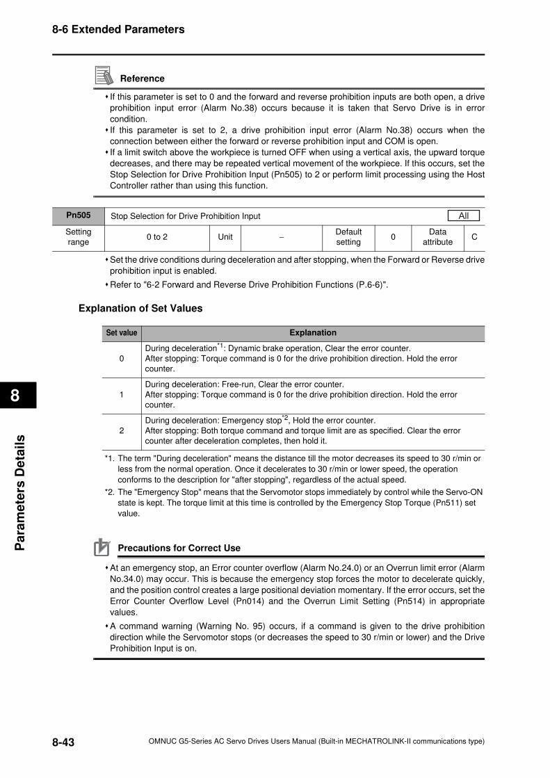
8-6 Extended Parameters
8
Pa
ram
ete
rs D
eta
ils
Reference
If this parameter is set to 0 and the forward and reverse prohibition inputs are both open, a drive
prohibition input error (Alarm No.38) occurs because it is taken that Servo Drive is in error
condition.
If this parameter is set to 2, a drive prohibition input error (Alarm No.38) occurs when the
connection between either the forward or reverse prohibition input and COM is open.
If a limit switch above the workpiece is turned OFF when using a vertical axis, the upward torque
decreases, and there may be repeated vertical movement of the workpiece. If this occurs, set the
Stop Selection for Drive Prohibition Input (Pn505) to 2 or perform limit processing using the Host
Controller rather than using this function.
Set the drive conditions during deceleration and after stopping, when the Forward or Reverse drive
prohibition input is enabled.
Refer to "6-2 Forward and Reverse Drive Prohibition Functions (P.6-6)".
Explanation of Set Values
*1. The term "During deceleration" means the distance till the motor decreases its speed to 30 r/min or
less from the normal operation. Once it decelerates to 30 r/min or lower speed, the operation
conforms to the description for "after stopping", regardless of the actual speed.
*2. The "Emergency Stop" means that the Servomotor stops immediately by control while the Servo-ON
state is kept. The torque limit at this time is controlled by the Emergency Stop Torque (Pn511) set
value.
Precautions for Correct Use
At an emergency stop, an Error counter overflow (Alarm No.24.0) or an Overrun limit error (Alarm
No.34.0) may occur. This is because the emergency stop forces the motor to decelerate quickly,
and the position control creates a large positional deviation momentary. If the error occurs, set the
Error Counter Overflow Level (Pn014) and the Overrun Limit Setting (Pn514) in appropriate
values.
A command warning (Warning No. 95) occurs, if a command is given to the drive prohibition
direction while the Servomotor stops (or decreases the speed to 30 r/min or lower) and the Drive
Prohibition Input is on.
Pn505 Stop Selection for Drive Prohibition Input
Setting
range0 to 2 Unit −
Default
setting0
Data
attributeC
All
Set value Explanation
0
During deceleration*1: Dynamic brake operation, Clear the error counter.
After stopping: Torque command is 0 for the drive prohibition direction. Hold the error
counter.
1
During deceleration: Free-run, Clear the error counter.
After stopping: Torque command is 0 for the drive prohibition direction. Hold the error
counter.
2
During deceleration: Emergency stop*2, Hold the error counter.
After stopping: Both torque command and torque limit are as specified. Clear the error
counter after deceleration completes, then hold it.
8-43 OMNUC G5-Series AC Servo Drives Users Manual (Built-in MECHATROLINK-II communications type)
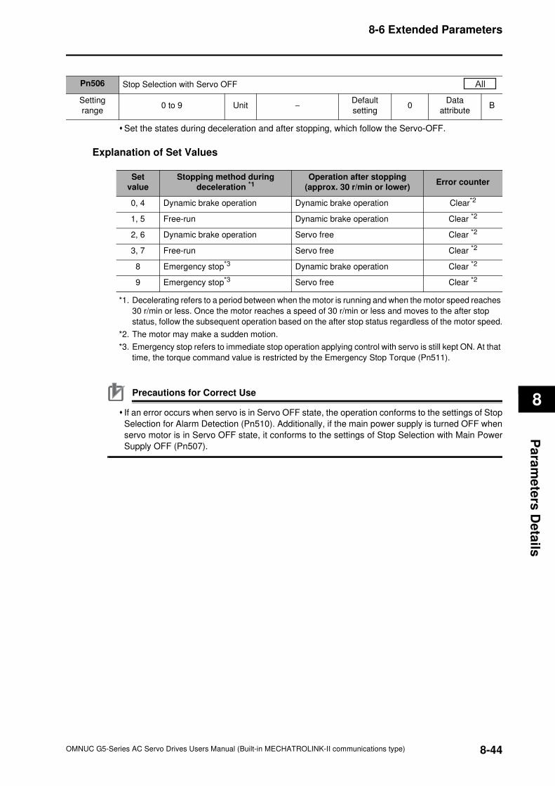
8-6 Extended Parameters
8
Pa
ram
ete
rs D
eta
ils
Set the states during deceleration and after stopping, which follow the Servo-OFF.
Explanation of Set Values
*1. Decelerating refers to a period between when the motor is running and when the motor speed reaches
30 r/min or less. Once the motor reaches a speed of 30 r/min or less and moves to the after stop
status, follow the subsequent operation based on the after stop status regardless of the motor speed.
*2. The motor may make a sudden motion.
*3. Emergency stop refers to immediate stop operation applying control with servo is still kept ON. At that
time, the torque command value is restricted by the Emergency Stop Torque (Pn511).
Precautions for Correct Use
If an error occurs when servo is in Servo OFF state, the operation conforms to the settings of Stop
Selection for Alarm Detection (Pn510). Additionally, if the main power supply is turned OFF when
servo motor is in Servo OFF state, it conforms to the settings of Stop Selection with Main Power
Supply OFF (Pn507).
Pn506 Stop Selection with Servo OFF
Setting
range0 to 9 Unit −
Default
setting0
Data
attributeB
All
Set
value
Stopping method during
deceleration *1Operation after stopping
(approx. 30 r/min or lower)Error counter
0, 4 Dynamic brake operation Dynamic brake operation Clear*2
1, 5 Free-run Dynamic brake operation Clear *2
2, 6 Dynamic brake operation Servo free Clear *2
3, 7 Free-run Servo free Clear *2
8 Emergency stop*3 Dynamic brake operation Clear *2
9 Emergency stop*3 Servo free Clear *2
8-44OMNUC G5-Series AC Servo Drives Users Manual (Built-in MECHATROLINK-II communications type)
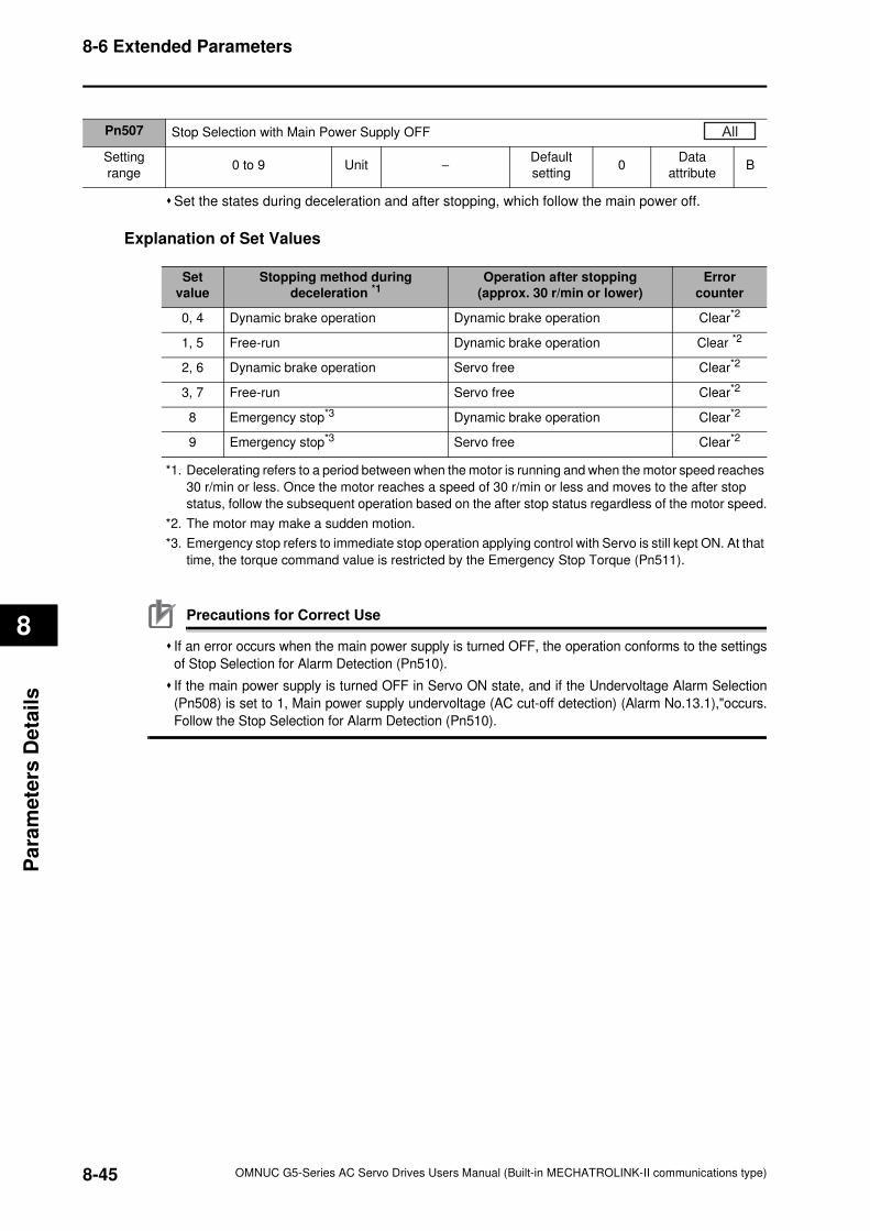
8-6 Extended Parameters
8
Pa
ram
ete
rs D
eta
ils
Set the states during deceleration and after stopping, which follow the main power off.
Explanation of Set Values
*1. Decelerating refers to a period between when the motor is running and when the motor speed reaches
30 r/min or less. Once the motor reaches a speed of 30 r/min or less and moves to the after stop
status, follow the subsequent operation based on the after stop status regardless of the motor speed.
*2. The motor may make a sudden motion.
*3. Emergency stop refers to immediate stop operation applying control with Servo is still kept ON. At that
time, the torque command value is restricted by the Emergency Stop Torque (Pn511).
Precautions for Correct Use
If an error occurs when the main power supply is turned OFF, the operation conforms to the settings
of Stop Selection for Alarm Detection (Pn510).
If the main power supply is turned OFF in Servo ON state, and if the Undervoltage Alarm Selection
(Pn508) is set to 1, Main power supply undervoltage (AC cut-off detection) (Alarm No.13.1),"occurs.
Follow the Stop Selection for Alarm Detection (Pn510).
Pn507 Stop Selection with Main Power Supply OFF
Setting
range0 to 9 Unit −
Default
setting0
Data
attributeB
All
Set
value
Stopping method during
deceleration *1Operation after stopping
(approx. 30 r/min or lower)
Error
counter
0, 4 Dynamic brake operation Dynamic brake operation Clear*2
1, 5 Free-run Dynamic brake operation Clear *2
2, 6 Dynamic brake operation Servo free Clear*2
3, 7 Free-run Servo free Clear*2
8 Emergency stop*3 Dynamic brake operation Clear*2
9 Emergency stop*3 Servo free Clear*2
8-45 OMNUC G5-Series AC Servo Drives Users Manual (Built-in MECHATROLINK-II communications type)
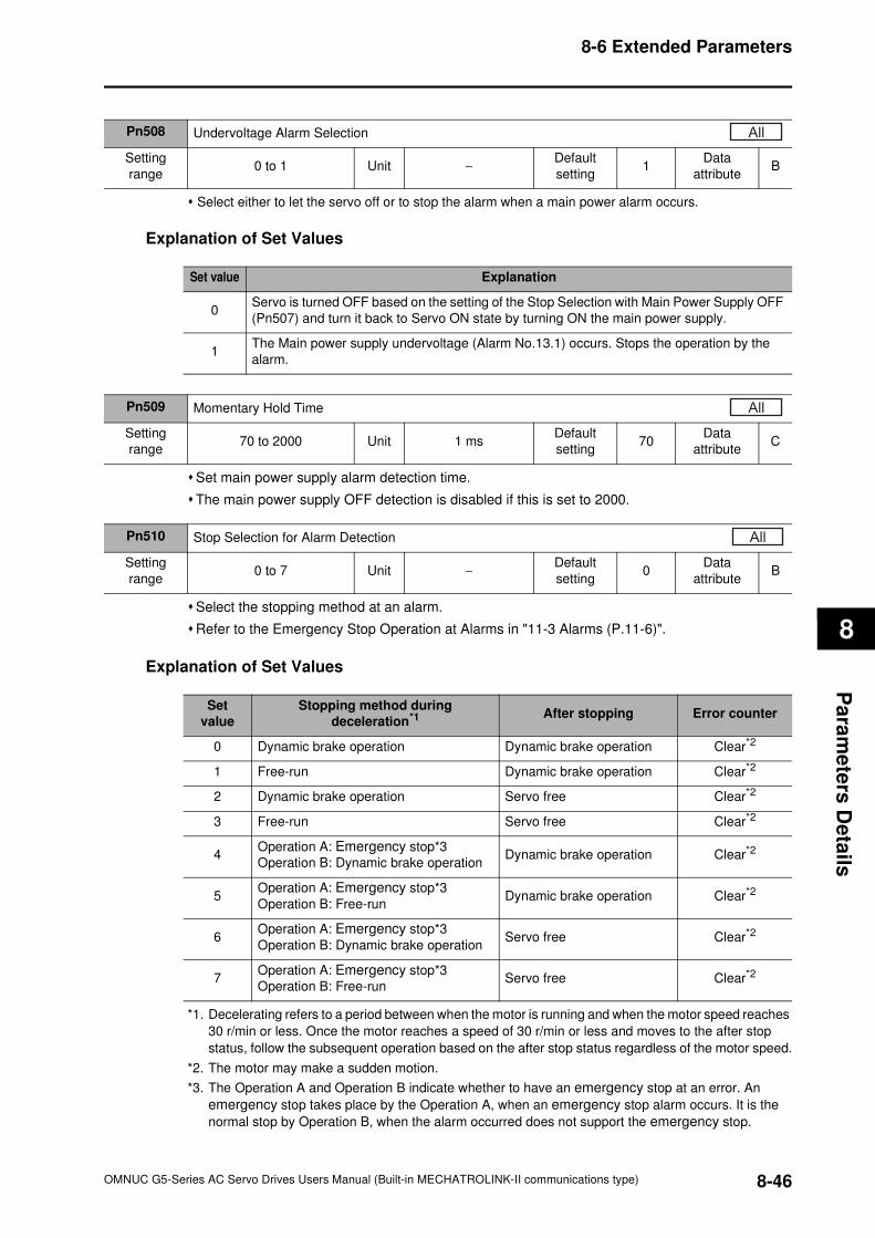
8-6 Extended Parameters
8
Pa
ram
ete
rs D
eta
ils
Select either to let the servo off or to stop the alarm when a main power alarm occurs.
Explanation of Set Values
Set main power supply alarm detection time.
The main power supply OFF detection is disabled if this is set to 2000.
Select the stopping method at an alarm.
Refer to the Emergency Stop Operation at Alarms in "11-3 Alarms (P.11-6)".
Explanation of Set Values
*1. Decelerating refers to a period between when the motor is running and when the motor speed reaches
30 r/min or less. Once the motor reaches a speed of 30 r/min or less and moves to the after stop
status, follow the subsequent operation based on the after stop status regardless of the motor speed.
*2. The motor may make a sudden motion.
*3. The Operation A and Operation B indicate whether to have an emergency stop at an error. An
emergency stop takes place by the Operation A, when an emergency stop alarm occurs. It is the
normal stop by Operation B, when the alarm occurred does not support the emergency stop.
Pn508 Undervoltage Alarm Selection
Setting
range0 to 1 Unit −
Default
setting1
Data
attributeB
All
Set value Explanation
0Servo is turned OFF based on the setting of the Stop Selection with Main Power Supply OFF
(Pn507) and turn it back to Servo ON state by turning ON the main power supply.
1The Main power supply undervoltage (Alarm No.13.1) occurs. Stops the operation by the
alarm.
Pn509 Momentary Hold Time
Setting
range70 to 2000 Unit 1 ms
Default
setting70
Data
attributeC
All
Pn510 Stop Selection for Alarm Detection
Setting
range0 to 7 Unit −
Default
setting0
Data
attributeB
All
Set
value
Stopping method during
deceleration*1 After stopping Error counter
0 Dynamic brake operation Dynamic brake operation Clear*2
1 Free-run Dynamic brake operation Clear*2
2 Dynamic brake operation Servo free Clear*2
3 Free-run Servo free Clear*2
4Operation A: Emergency stop*3
Operation B: Dynamic brake operationDynamic brake operation Clear*2
5Operation A: Emergency stop*3
Operation B: Free-runDynamic brake operation Clear*2
6Operation A: Emergency stop*3
Operation B: Dynamic brake operationServo free Clear*2
7Operation A: Emergency stop*3
Operation B: Free-runServo free Clear*2
8-46OMNUC G5-Series AC Servo Drives Users Manual (Built-in MECHATROLINK-II communications type)
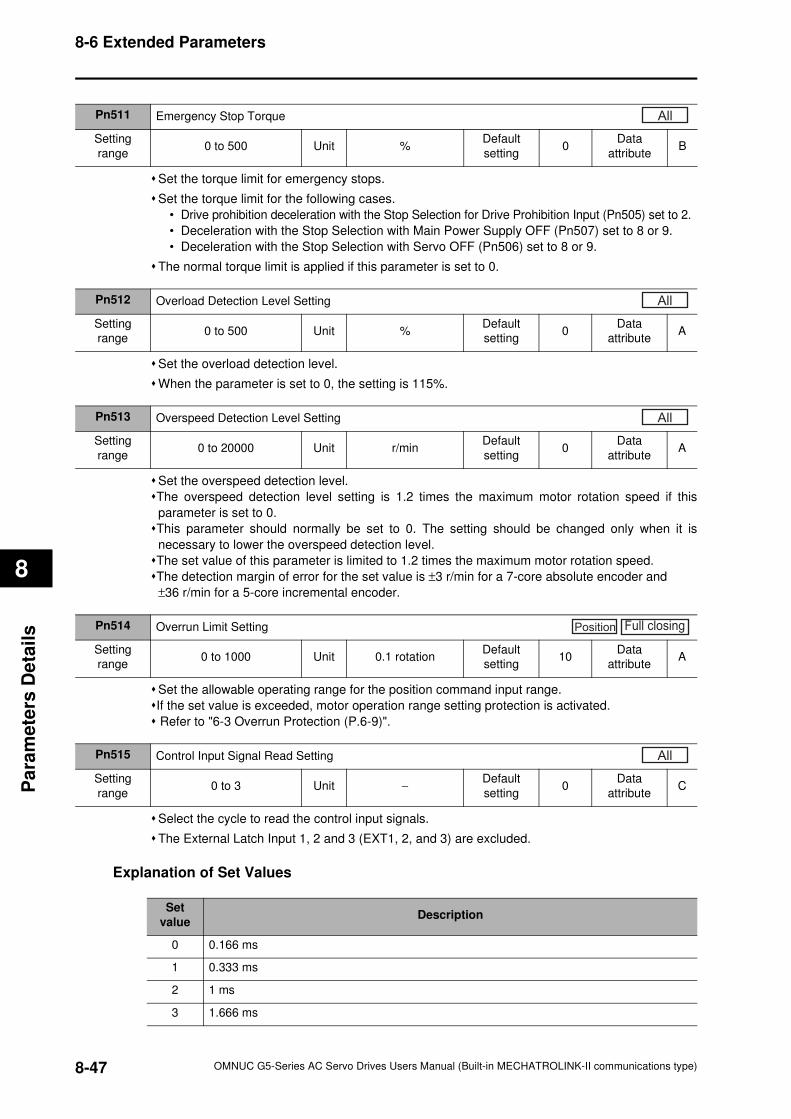
8-6 Extended Parameters
8
Pa
ram
ete
rs D
eta
ils
Set the torque limit for emergency stops.
Set the torque limit for the following cases.
• Drive prohibition deceleration with the Stop Selection for Drive Prohibition Input (Pn505) set to 2.
• Deceleration with the Stop Selection with Main Power Supply OFF (Pn507) set to 8 or 9.
• Deceleration with the Stop Selection with Servo OFF (Pn506) set to 8 or 9.
The normal torque limit is applied if this parameter is set to 0.
Set the overload detection level.
When the parameter is set to 0, the setting is 115%.
Set the overspeed detection level.
The overspeed detection level setting is 1.2 times the maximum motor rotation speed if this
parameter is set to 0.
This parameter should normally be set to 0. The setting should be changed only when it is
necessary to lower the overspeed detection level.
The set value of this parameter is limited to 1.2 times the maximum motor rotation speed.
The detection margin of error for the set value is ±3 r/min for a 7-core absolute encoder and
±36 r/min for a 5-core incremental encoder.
Set the allowable operating range for the position command input range.
If the set value is exceeded, motor operation range setting protection is activated.
Refer to "6-3 Overrun Protection (P.6-9)".
Select the cycle to read the control input signals.
The External Latch Input 1, 2 and 3 (EXT1, 2, and 3) are excluded.
Explanation of Set Values
Pn511 Emergency Stop Torque
Setting
range0 to 500 Unit %
Default
setting0
Data
attributeB
All
Pn512 Overload Detection Level Setting
Setting
range0 to 500 Unit %
Default
setting0
Data
attributeA
All
Pn513 Overspeed Detection Level Setting
Setting
range0 to 20000 Unit r/min
Default
setting0
Data
attributeA
All
Pn514 Overrun Limit Setting
Setting
range0 to 1000 Unit 0.1 rotation
Default
setting10
Data
attributeA
Position Full closing
Pn515 Control Input Signal Read Setting
Setting
range0 to 3 Unit −
Default
setting0
Data
attributeC
All
Set
valueDescription
0 0.166 ms
1 0.333 ms
2 1 ms
3 1.666 ms
8-47 OMNUC G5-Series AC Servo Drives Users Manual (Built-in MECHATROLINK-II communications type)
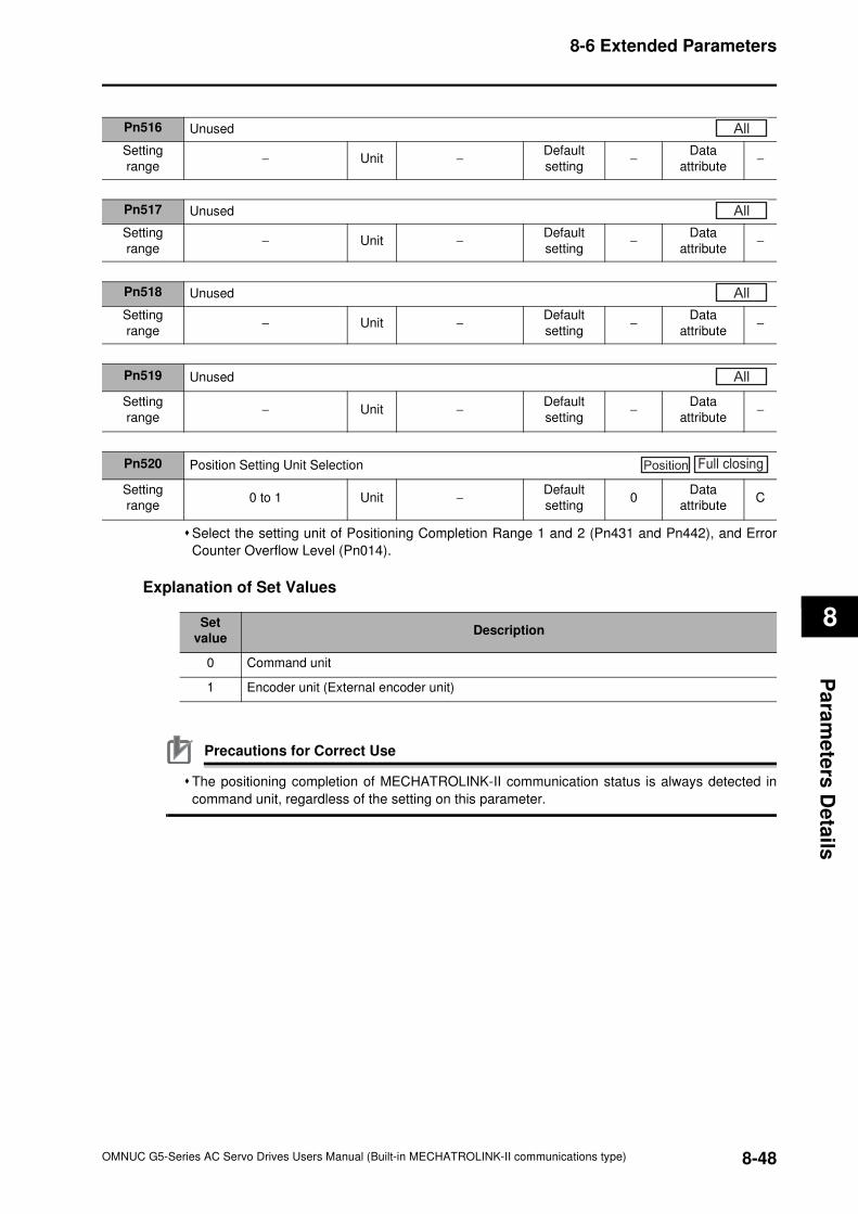
8-6 Extended Parameters
8
Pa
ram
ete
rs D
eta
ils
Select the setting unit of Positioning Completion Range 1 and 2 (Pn431 and Pn442), and Error
Counter Overflow Level (Pn014).
Explanation of Set Values
Precautions for Correct Use
The positioning completion of MECHATROLINK-II communication status is always detected in
command unit, regardless of the setting on this parameter.
Pn516 Unused
Setting
range− Unit −
Default
setting−
Data
attribute−
All
Pn517 Unused
Setting
range− Unit −
Default
setting−
Data
attribute−
All
Pn518 Unused
Setting
range− Unit −
Default
setting−
Data
attribute−
All
Pn519 Unused
Setting
range− Unit −
Default
setting−
Data
attribute−
All
Pn520 Position Setting Unit Selection
Setting
range0 to 1 Unit −
Default
setting0
Data
attributeC
Position Full closing
Set
valueDescription
0 Command unit
1 Encoder unit (External encoder unit)
8-48OMNUC G5-Series AC Servo Drives Users Manual (Built-in MECHATROLINK-II communications type)
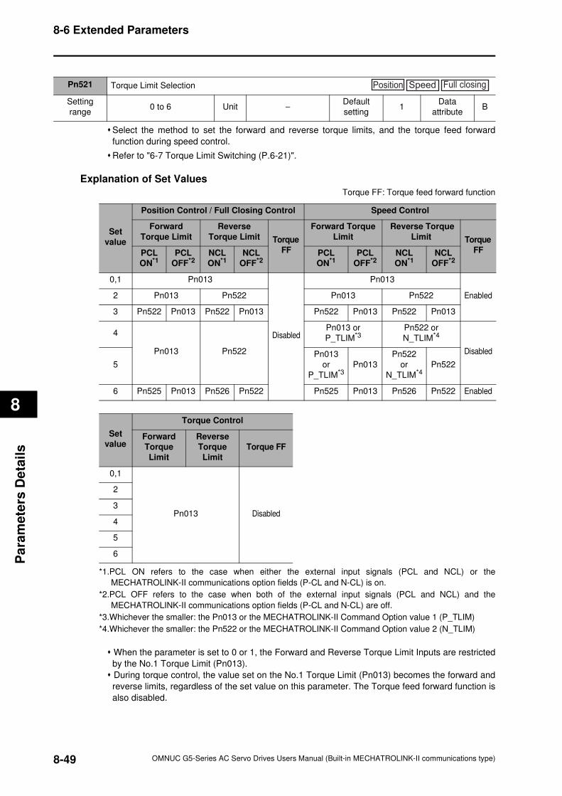
8-6 Extended Parameters
8
Pa
ram
ete
rs D
eta
ils
Select the method to set the forward and reverse torque limits, and the torque feed forward
function during speed control.
Refer to "6-7 Torque Limit Switching (P.6-21)".
Explanation of Set Values
Torque FF: Torque feed forward function
*1.PCL ON refers to the case when either the external input signals (PCL and NCL) or the
MECHATROLINK-II communications option fields (P-CL and N-CL) is on.
*2.PCL OFF refers to the case when both of the external input signals (PCL and NCL) and the
MECHATROLINK-II communications option fields (P-CL and N-CL) are off.
*3.Whichever the smaller: the Pn013 or the MECHATROLINK-II Command Option value 1 (P_TLIM)
*4.Whichever the smaller: the Pn522 or the MECHATROLINK-II Command Option value 2 (N_TLIM)
When the parameter is set to 0 or 1, the Forward and Reverse Torque Limit Inputs are restricted
by the No.1 Torque Limit (Pn013).
During torque control, the value set on the No.1 Torque Limit (Pn013) becomes the forward and
reverse limits, regardless of the set value on this parameter. The Torque feed forward function is
also disabled.
Pn521 Torque Limit Selection
Setting
range0 to 6 Unit −
Default
setting1
Data
attributeB
Position Speed Full closing
Set
value
Position Control / Full Closing Control Speed Control
Forward
Torque Limit
Reverse
Torque Limit Torque
FF
Forward Torque
Limit
Reverse Torque
Limit Torque
FFPCL
ON*1PCL
OFF*2NCL
ON*1NCL
OFF*2PCL
ON*1PCL
OFF*2NCL
ON*1NCL
OFF*2
0,1 Pn013
Disabled
Pn013
Enabled2 Pn013 Pn522 Pn013 Pn522
3 Pn522 Pn013 Pn522 Pn013 Pn522 Pn013 Pn522 Pn013
4
Pn013 Pn522
Pn013 or
P_TLIM*3Pn522 or
N_TLIM*4
Disabled
5
Pn013
or
P_TLIM*3Pn013
Pn522
or
N_TLIM*4Pn522
6 Pn525 Pn013 Pn526 Pn522 Pn525 Pn013 Pn526 Pn522 Enabled
Set
value
Torque Control
Forward
Torque
Limit
Reverse
Torque
Limit
Torque FF
0,1
Pn013 Disabled
2
3
4
5
6
8-49 OMNUC G5-Series AC Servo Drives Users Manual (Built-in MECHATROLINK-II communications type)
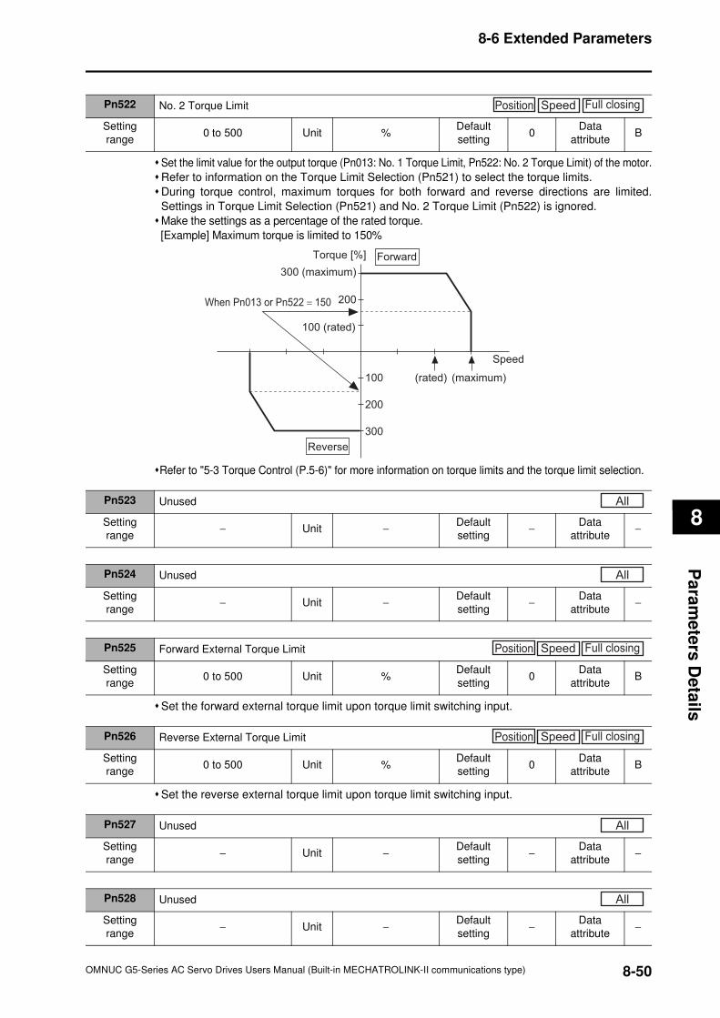
8-6 Extended Parameters
8
Pa
ram
ete
rs D
eta
ils
Set the limit value for the output torque (Pn013: No. 1 Torque Limit, Pn522: No. 2 Torque Limit) of the motor.
Refer to information on the Torque Limit Selection (Pn521) to select the torque limits.
During torque control, maximum torques for both forward and reverse directions are limited.
Settings in Torque Limit Selection (Pn521) and No. 2 Torque Limit (Pn522) is ignored.
Make the settings as a percentage of the rated torque.
[Example] Maximum torque is limited to 150%
Refer to "5-3 Torque Control (P.5-6)" for more information on torque limits and the torque limit selection.
Set the forward external torque limit upon torque limit switching input.
Set the reverse external torque limit upon torque limit switching input.
Pn522 No. 2 Torque Limit
Setting
range0 to 500 Unit %
Default
setting0
Data
attributeB
Position Speed Full closing
Speed
200
100 (rated)
(rated)100
200
300
Torque [%]
300 (maximum)
(maximum)
Reverse
Forward
When Pn013 or Pn522 = 150
Pn523 Unused
Setting
range− Unit −
Default
setting−
Data
attribute−
All
Pn524 Unused
Setting
range− Unit −
Default
setting−
Data
attribute−
All
Pn525 Forward External Torque Limit
Setting
range0 to 500 Unit %
Default
setting0
Data
attributeB
Position Speed Full closing
Pn526 Reverse External Torque Limit
Setting
range0 to 500 Unit %
Default
setting0
Data
attributeB
Position Speed Full closing
Pn527 Unused
Setting
range− Unit −
Default
setting−
Data
attribute−
All
Pn528 Unused
Setting
range− Unit −
Default
setting−
Data
attribute−
All
8-50OMNUC G5-Series AC Servo Drives Users Manual (Built-in MECHATROLINK-II communications type)
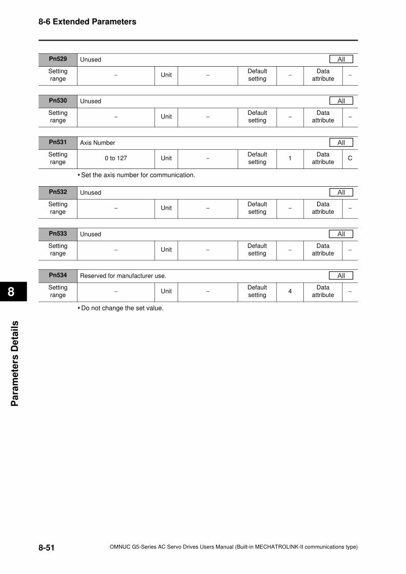
8-6 Extended Parameters
8
Pa
ram
ete
rs D
eta
ils
Set the axis number for communication.
Do not change the set value.
Pn529 Unused
Setting
range− Unit −
Default
setting−
Data
attribute−
All
Pn530 Unused
Setting
range− Unit −
Default
setting−
Data
attribute−
All
Pn531 Axis Number
Setting
range0 to 127 Unit −
Default
setting1
Data
attributeC
All
Pn532 Unused
Setting
range− Unit −
Default
setting−
Data
attribute−
All
Pn533 Unused
Setting
range− Unit −
Default
setting−
Data
attribute−
Pn534 Reserved for manufacturer use.
Setting
range− Unit −
Default
setting4
Data
attribute−
All
All
8-51 OMNUC G5-Series AC Servo Drives Users Manual (Built-in MECHATROLINK-II communications type)
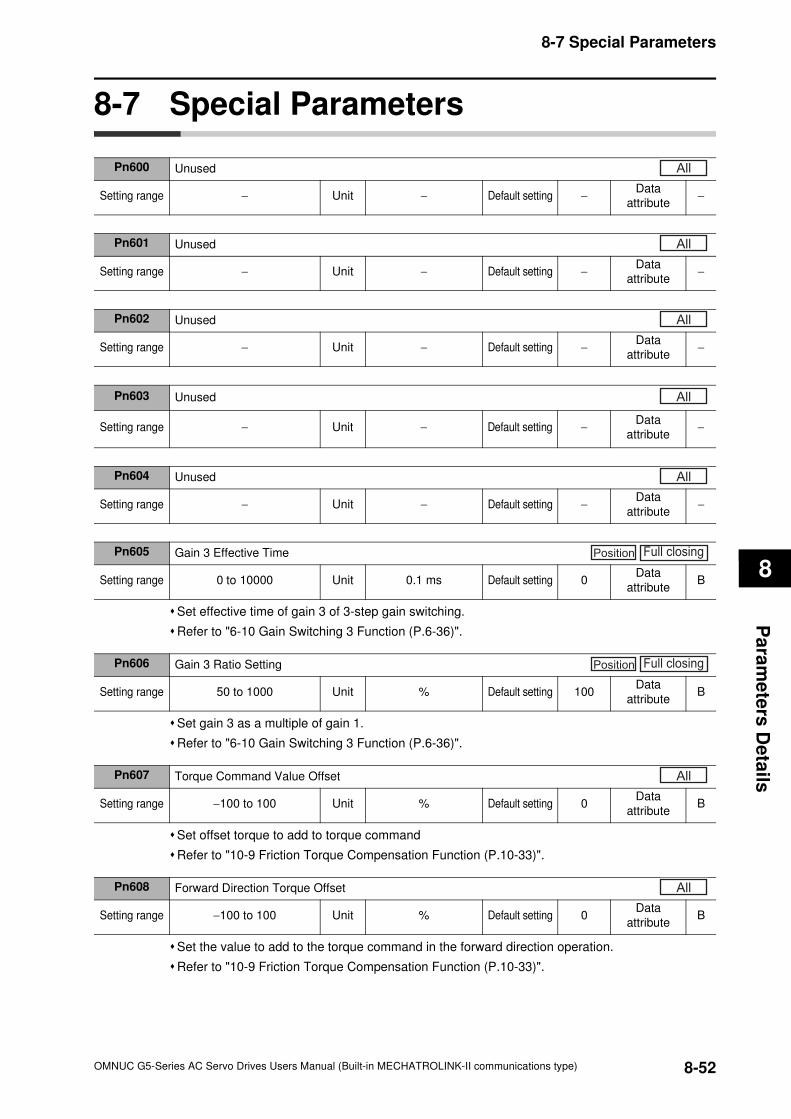
8-7 Special Parameters
8
Pa
ram
ete
rs D
eta
ils
8-7 Special Parameters
Set effective time of gain 3 of 3-step gain switching.
Refer to "6-10 Gain Switching 3 Function (P.6-36)".
Set gain 3 as a multiple of gain 1.
Refer to "6-10 Gain Switching 3 Function (P.6-36)".
Set offset torque to add to torque command
Refer to "10-9 Friction Torque Compensation Function (P.10-33)".
Set the value to add to the torque command in the forward direction operation.
Refer to "10-9 Friction Torque Compensation Function (P.10-33)".
Pn600 Unused
Setting range − Unit − Default setting −Data
attribute−
All
Pn601 Unused
Setting range − Unit − Default setting −Data
attribute−
All
Pn602 Unused
Setting range − Unit − Default setting −Data
attribute−
All
Pn603 Unused
Setting range − Unit − Default setting −Data
attribute−
All
Pn604 Unused
Setting range − Unit − Default setting −Data
attribute−
All
Pn605 Gain 3 Effective Time
Setting range 0 to 10000 Unit 0.1 ms Default setting 0Data
attributeB
Position Full closing
Pn606 Gain 3 Ratio Setting
Setting range 50 to 1000 Unit % Default setting 100Data
attributeB
Position Full closing
Pn607 Torque Command Value Offset
Setting range −100 to 100 Unit % Default setting 0Data
attributeB
All
Pn608 Forward Direction Torque Offset
Setting range −100 to 100 Unit % Default setting 0Data
attributeB
All
8-52OMNUC G5-Series AC Servo Drives Users Manual (Built-in MECHATROLINK-II communications type)
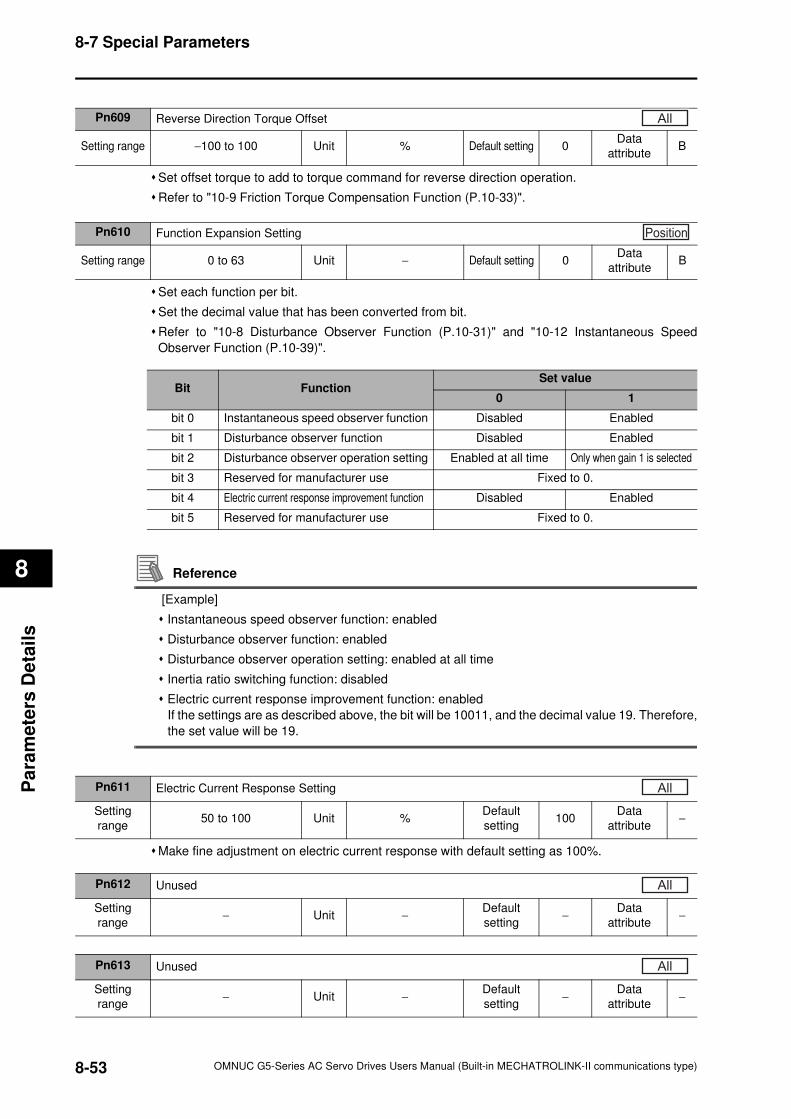
8-7 Special Parameters
8
Pa
ram
ete
rs D
eta
ils
Set offset torque to add to torque command for reverse direction operation.
Refer to "10-9 Friction Torque Compensation Function (P.10-33)".
Set each function per bit.
Set the decimal value that has been converted from bit.
Refer to "10-8 Disturbance Observer Function (P.10-31)" and "10-12 Instantaneous Speed
Observer Function (P.10-39)".
Reference
[Example]
Instantaneous speed observer function: enabled
Disturbance observer function: enabled
Disturbance observer operation setting: enabled at all time
Inertia ratio switching function: disabled
Electric current response improvement function: enabled
If the settings are as described above, the bit will be 10011, and the decimal value 19. Therefore,
the set value will be 19.
Make fine adjustment on electric current response with default setting as 100%.
Pn609 Reverse Direction Torque Offset
Setting range −100 to 100 Unit % Default setting 0Data
attributeB
All
Pn610 Function Expansion Setting
Setting range 0 to 63 Unit − Default setting 0Data
attributeB
Position
Bit FunctionSet value
0 1
bit 0 Instantaneous speed observer function Disabled Enabled
bit 1 Disturbance observer function Disabled Enabled
bit 2 Disturbance observer operation setting Enabled at all time Only when gain 1 is selected
bit 3 Reserved for manufacturer use Fixed to 0.
bit 4 Electric current response improvement function Disabled Enabled
bit 5 Reserved for manufacturer use Fixed to 0.
Pn611 Electric Current Response Setting
Setting
range50 to 100 Unit %
Default
setting100
Data
attribute−
All
Pn612 Unused
Setting
range− Unit −
Default
setting−
Data
attribute−
All
Pn613 Unused
Setting
range− Unit −
Default
setting−
Data
attribute−
All
8-53 OMNUC G5-Series AC Servo Drives Users Manual (Built-in MECHATROLINK-II communications type)
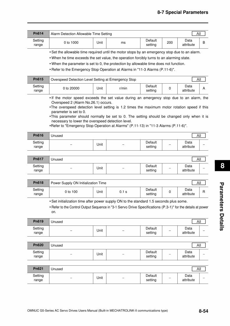
8-7 Special Parameters
8
Pa
ram
ete
rs D
eta
ils
Set the allowable time required until the motor stops by an emergency stop due to an alarm.
When he time exceeds the set value, the operation forcibly turns to an alarming state.
When the parameter is set to 0, the protection by allowable time does not function.
Refer to the Emergency Stop Operation at Alarms in "11-3 Alarms (P.11-6)".
If the motor speed exceeds the set value during an emergency stop due to an alarm, the
Overspeed 2 (Alarm No.26.1) occurs.
The overspeed detection level setting is 1.2 times the maximum motor rotation speed if this
parameter is set to 0.
This parameter should normally be set to 0. The setting should be changed only when it is
necessary to lower the overspeed detection level.
Refer to "Emergency Stop Operation at Alarms" (P.11-13) in "11-3 Alarms (P.11-6)".
Set initialization time after power supply ON to the standard 1.5 seconds plus some.
Refer to the Control Output Sequence in "3-1 Servo Drive Specifications (P.3-1)" for the details at power
on.
Pn614 Alarm Detection Allowable Time Setting
Setting
range0 to 1000 Unit ms
Default
setting200
Data
attributeB
All
Pn615 Overspeed Detection Level Setting at Emergency Stop
Setting
range0 to 20000 Unit r/min
Default
setting0
Data
attributeA
All
Pn616 Unused
Setting
range− Unit −
Default
setting−
Data
attribute−
All
Pn617 Unused
Setting
range− Unit −
Default
setting−
Data
attribute−
All
Pn618 Power Supply ON Initialization Time
Setting
range0 to 100 Unit 0.1 s
Default
setting0
Data
attributeR
All
Pn619 Unused
Setting
range− Unit −
Default
setting−
Data
attribute−
All
Pn620 Unused
Setting
range− Unit −
Default
setting−
Data
attribute−
All
Pn621 Unused
Setting
range− Unit −
Default
setting−
Data
attribute−
All
8-54OMNUC G5-Series AC Servo Drives Users Manual (Built-in MECHATROLINK-II communications type)
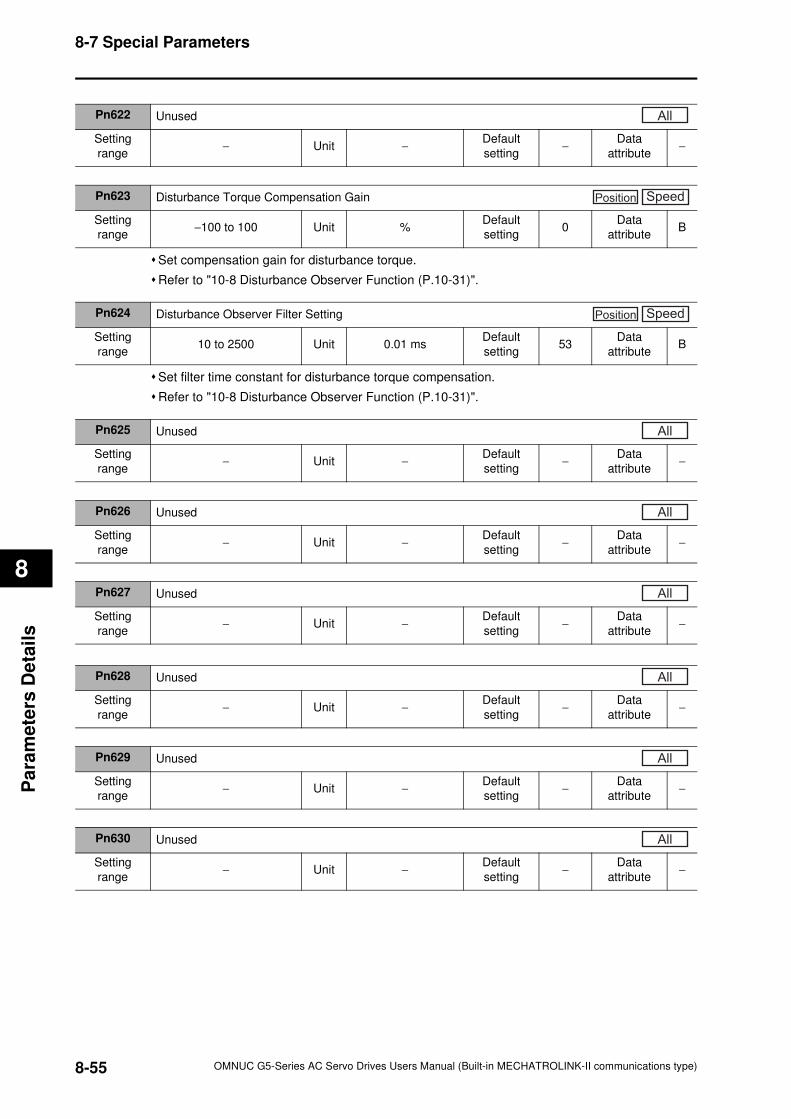
8-7 Special Parameters
8
Pa
ram
ete
rs D
eta
ils
Set compensation gain for disturbance torque.
Refer to "10-8 Disturbance Observer Function (P.10-31)".
Set filter time constant for disturbance torque compensation.
Refer to "10-8 Disturbance Observer Function (P.10-31)".
Pn622 Unused
Setting
range− Unit −
Default
setting−
Data
attribute−
All
Pn623 Disturbance Torque Compensation Gain
Setting
range−100 to 100 Unit %
Default
setting0
Data
attributeB
Position Speed
Pn624 Disturbance Observer Filter Setting
Setting
range10 to 2500 Unit 0.01 ms
Default
setting53
Data
attributeB
Position Speed
Pn625 Unused
Setting
range− Unit −
Default
setting−
Data
attribute−
All
Pn626 Unused
Setting
range− Unit −
Default
setting−
Data
attribute−
All
Pn627 Unused
Setting
range− Unit −
Default
setting−
Data
attribute−
All
Pn628 Unused
Setting
range− Unit −
Default
setting−
Data
attribute−
All
Pn629 Unused
Setting
range− Unit −
Default
setting−
Data
attribute−
All
Pn630 Unused
Setting
range− Unit −
Default
setting−
Data
attribute−
All
8-55 OMNUC G5-Series AC Servo Drives Users Manual (Built-in MECHATROLINK-II communications type)
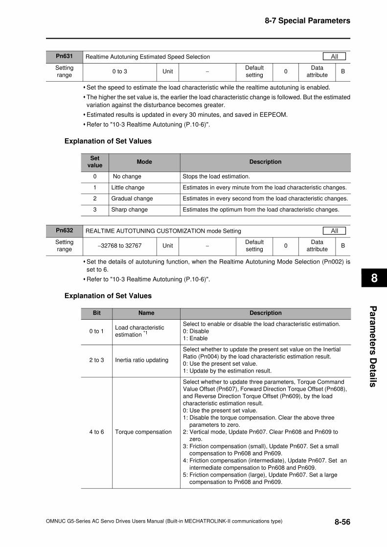
8-7 Special Parameters
8
Pa
ram
ete
rs D
eta
ils
Set the speed to estimate the load characteristic while the realtime autotuning is enabled.
The higher the set value is, the earlier the load characteristic change is followed. But the estimated
variation against the disturbance becomes greater.
Estimated results is updated in every 30 minutes, and saved in EEPEOM.
Refer to "10-3 Realtime Autotuning (P.10-6)".
Explanation of Set Values
Set the details of autotuning function, when the Realtime Autotuning Mode Selection (Pn002) is
set to 6.
Refer to "10-3 Realtime Autotuning (P.10-6)".
Explanation of Set Values
Pn631 Realtime Autotuning Estimated Speed Selection
Setting
range0 to 3 Unit −
Default
setting0
Data
attributeB
All
Set
valueMode Description
0 No change Stops the load estimation.
1 Little change Estimates in every minute from the load characteristic changes.
2 Gradual change Estimates in every second from the load characteristic changes.
3 Sharp change Estimates the optimum from the load characteristic changes.
Pn632 REALTIME AUTOTUNING CUSTOMIZATION mode Setting
Setting
range−32768 to 32767 Unit −
Default
setting0
Data
attributeB
All
Bit Name Description
0 to 1Load characteristic
estimation *1
Select to enable or disable the load characteristic estimation.
0: Disable
1: Enable
2 to 3 Inertia ratio updating
Select whether to update the present set value on the Inertial
Ratio (Pn004) by the load characteristic estimation result.
0: Use the present set value.
1: Update by the estimation result.
4 to 6 Torque compensation
Select whether to update three parameters, Torque Command
Value Offset (Pn607), Forward Direction Torque Offset (Pn608),
and Reverse Direction Torque Offset (Pn609), by the load
characteristic estimation result.
0: Use the present set value.
1: Disable the torque compensation. Clear the above three
parameters to zero.
2: Vertical mode, Update Pn607. Clear Pn608 and Pn609 to
zero.
3: Friction compensation (small), Update Pn607. Set a small
compensation to Pn608 and Pn609.
4: Friction compensation (intermediate), Update Pn607. Set an
intermediate compensation to Pn608 and Pn609.
5: Friction compensation (large), Update Pn607. Set a large
compensation to Pn608 and Pn609.
8-56OMNUC G5-Series AC Servo Drives Users Manual (Built-in MECHATROLINK-II communications type)
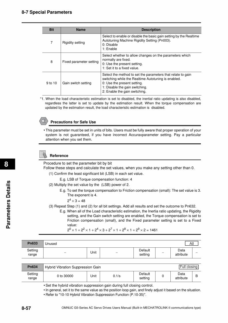
8-7 Special Parameters
8
Pa
ram
ete
rs D
eta
ils
*1. When the load characteristic estimation is set to disabled, the inertial ratio updating is also disabled,
regardless the latter is set to update by the estimation result. When the torque compensation are
updated by the estimation result, the load characteristic estimation is disabled.
Precautions for Safe Use
This parameter must be set in units of bits. Users must be fully aware that proper operation of your
system is not guaranteed, if you have incorrect Accuraxparameter setting. Pay a particular
attention when you set them.
Reference
Procedure to set the parameter bit by bit
Follow these steps and calculate the set values, when you make any setting other than 0.
(1) Confirm the least significant bit (LSB) in each set value.
E.g. LSB of Torque compensation function: 4
(2) Multiply the set value by the (LSB) power of 2.
E.g. To set the torque compensation to Friction compensation (small): The set value is 3.
The exponent is 4.
24 × 3 = 48
(3) Repeat Step (1) and (2) for all bit settings. Add all results and set the outcome to Pn632.
E.g. When all of the Load characteristic estimation, the Inertia ratio updating, the Rigidity
setting, and the Gain switch setting are enabled, the Torque compensation is set to
Friction compensation (small), and the Fixed parameter setting is set to a Fixed
value:
20 × 1 + 22 × 1 + 24 × 3 + 27 × 1 + 28 × 1 + 29 × 2 = 1461
Set the hybrid vibration suppression gain during full closing control.
In general, set it to the same value as the position loop gain, and finely adjust it based on the situation.
Refer to "10-10 Hybrid Vibration Suppression Function (P.10-35)".
7 Rigidity setting
Select to enable or disable the basic gain setting by the Realtime
Autotuning Machine Rigidity Setting (Pn003).
0: Disable
1: Enable
8 Fixed parameter setting
Select whether to allow changes on the parameters which
normally are fixed.
0: Use the present setting.
1: Set it to a fixed value.
9 to 10 Gain switch setting
Select the method to set the parameters that relate to gain
switching while the Realtime Autotuning is enabled.
0: Use the present setting.
1: Disable the gain switching.
2: Enable the gain switching.
Bit Name Description
Pn633 Unused
Setting
range− Unit −
Default
setting−
Data
attribute−
All
Pn634 Hybrid Vibration Suppression Gain
Setting
range0 to 30000 Unit 0.1/s
Default
setting0
Data
attributeB
Full closing
8-57 OMNUC G5-Series AC Servo Drives Users Manual (Built-in MECHATROLINK-II communications type)
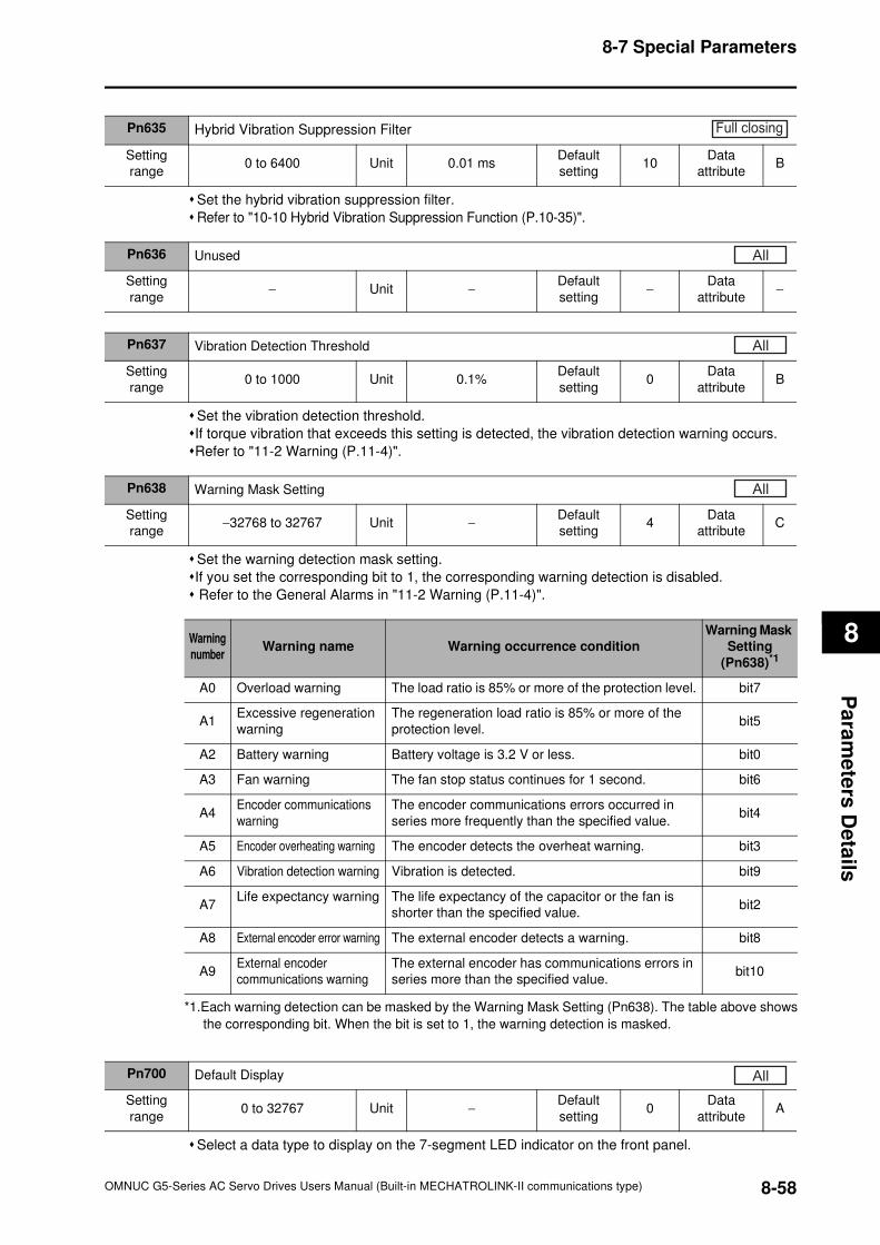
8-7 Special Parameters
8
Pa
ram
ete
rs D
eta
ils
Set the hybrid vibration suppression filter.
Refer to "10-10 Hybrid Vibration Suppression Function (P.10-35)".
Set the vibration detection threshold.
If torque vibration that exceeds this setting is detected, the vibration detection warning occurs.
Refer to "11-2 Warning (P.11-4)".
Set the warning detection mask setting.
If you set the corresponding bit to 1, the corresponding warning detection is disabled.
Refer to the General Alarms in "11-2 Warning (P.11-4)".
Select a data type to display on the 7-segment LED indicator on the front panel.
Pn635 Hybrid Vibration Suppression Filter
Setting
range0 to 6400 Unit 0.01 ms
Default
setting10
Data
attributeB
Full closing
Pn636 Unused
Setting
range− Unit −
Default
setting−
Data
attribute−
All
Pn637 Vibration Detection Threshold
Setting
range0 to 1000 Unit 0.1%
Default
setting0
Data
attributeB
All
Pn638 Warning Mask Setting
Setting
range−32768 to 32767 Unit −
Default
setting4
Data
attributeC
All
Warning
number Warning name Warning occurrence condition
Warning Mask
Setting
(Pn638)*1
A0 Overload warning The load ratio is 85% or more of the protection level. bit7
A1Excessive regeneration
warning
The regeneration load ratio is 85% or more of the
protection level.bit5
A2 Battery warning Battery voltage is 3.2 V or less. bit0
A3 Fan warning The fan stop status continues for 1 second. bit6
A4Encoder communications
warning
The encoder communications errors occurred in
series more frequently than the specified value.bit4
A5 Encoder overheating warning The encoder detects the overheat warning. bit3
A6 Vibration detection warning Vibration is detected. bit9
A7Life expectancy warning The life expectancy of the capacitor or the fan is
shorter than the specified value.bit2
A8 External encoder error warning The external encoder detects a warning. bit8
A9External encoder
communications warning
The external encoder has communications errors in
series more than the specified value.bit10
*1.Each warning detection can be masked by the Warning Mask Setting (Pn638). The table above shows
the corresponding bit. When the bit is set to 1, the warning detection is masked.
Pn700 Default Display
Setting
range0 to 32767 Unit −
Default
setting0
Data
attributeA
All
8-58OMNUC G5-Series AC Servo Drives Users Manual (Built-in MECHATROLINK-II communications type)
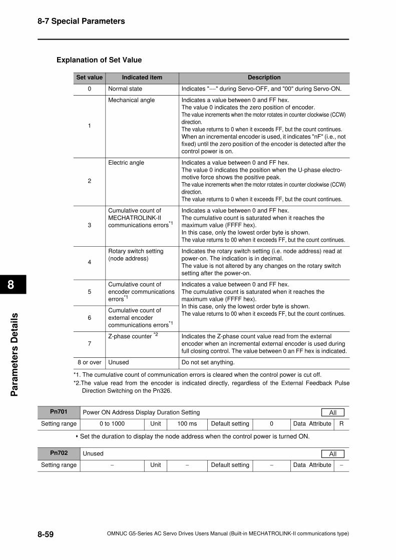
8-7 Special Parameters
8
Pa
ram
ete
rs D
eta
ils
Explanation of Set Value
Set the duration to display the node address when the control power is turned ON.
Set value Indicated item Description
0 Normal state Indicates "−−" during Servo-OFF, and "00" during Servo-ON.
1
Mechanical angle Indicates a value between 0 and FF hex.
The value 0 indicates the zero position of encoder.
The value increments when the motor rotates in counter clockwise (CCW)
direction.
The value returns to 0 when it exceeds FF, but the count continues.
When an incremental encoder is used, it indicates "nF" (i.e., not
fixed) until the zero position of the encoder is detected after the
control power is on.
2
Electric angle Indicates a value between 0 and FF hex.
The value 0 indicates the position when the U-phase electro-
motive force shows the positive peak.
The value increments when the motor rotates in counter clockwise (CCW)
direction.
The value returns to 0 when it exceeds FF, but the count continues.
3
Cumulative count of
MECHATROLINK-II
communications errors*1
Indicates a value between 0 and FF hex.
The cumulative count is saturated when it reaches the
maximum value (FFFF hex).
In this case, only the lowest order byte is shown.
The value returns to 00 when it exceeds FF, but the count continues.
4
Rotary switch setting
(node address)
Indicates the rotary switch setting (i.e. node address) read at
power-on. The indication is in decimal.
The value is not altered by any changes on the rotary switch
setting after the power-on.
5
Cumulative count of
encoder communications
errors*1
Indicates a value between 0 and FF hex.
The cumulative count is saturated when it reaches the
maximum value (FFFF hex).
In this case, only the lowest order byte is shown.
The value returns to 00 when it exceeds FF, but the count continues.6
Cumulative count of
external encoder
communications errors*1
7
Z-phase counter *2 Indicates the Z-phase count value read from the external
encoder when an incremental external encoder is used during
full closing control. The value between 0 an FF hex is indicated.
8 or over Unused Do not set anything.
*1. The cumulative count of communication errors is cleared when the control power is cut off.
*2.The value read from the encoder is indicated directly, regardless of the External Feedback Pulse
Direction Switching on the Pn326.
Pn701 Power ON Address Display Duration Setting
Setting range 0 to 1000 Unit 100 ms Default setting 0 Data Attribute R
All
Pn702 Unused
Setting range − Unit − Default setting − Data Attribute −
All
8-59 OMNUC G5-Series AC Servo Drives Users Manual (Built-in MECHATROLINK-II communications type)
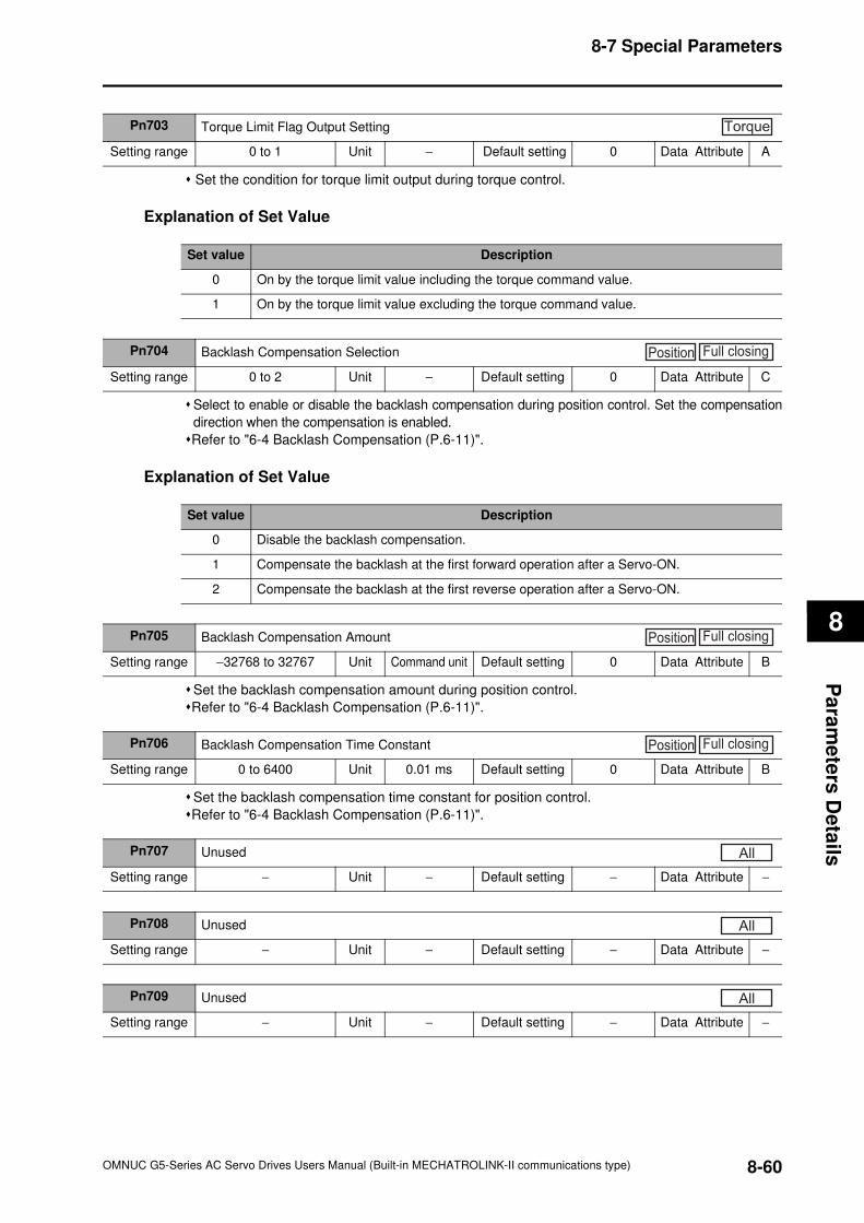
8-7 Special Parameters
8
Pa
ram
ete
rs D
eta
ils
Set the condition for torque limit output during torque control.
Explanation of Set Value
Select to enable or disable the backlash compensation during position control. Set the compensation
direction when the compensation is enabled.
Refer to "6-4 Backlash Compensation (P.6-11)".
Explanation of Set Value
Set the backlash compensation amount during position control.
Refer to "6-4 Backlash Compensation (P.6-11)".
Set the backlash compensation time constant for position control.
Refer to "6-4 Backlash Compensation (P.6-11)".
Pn703 Torque Limit Flag Output Setting
Setting range 0 to 1 Unit − Default setting 0 Data Attribute A
Torque
Set value Description
0 On by the torque limit value including the torque command value.
1 On by the torque limit value excluding the torque command value.
Pn704 Backlash Compensation Selection
Setting range 0 to 2 Unit − Default setting 0 Data Attribute C
Position Full closing
Set value Description
0 Disable the backlash compensation.
1 Compensate the backlash at the first forward operation after a Servo-ON.
2 Compensate the backlash at the first reverse operation after a Servo-ON.
Pn705 Backlash Compensation Amount
Setting range −32768 to 32767 Unit Command unit Default setting 0 Data Attribute B
Position Full closing
Pn706 Backlash Compensation Time Constant
Setting range 0 to 6400 Unit 0.01 ms Default setting 0 Data Attribute B
Position Full closing
Pn707 Unused
Setting range − Unit − Default setting − Data Attribute −
All
Pn708 Unused
Setting range − Unit − Default setting − Data Attribute −
All
Pn709 Unused
Setting range − Unit − Default setting − Data Attribute −
All
8-60OMNUC G5-Series AC Servo Drives Users Manual (Built-in MECHATROLINK-II communications type)
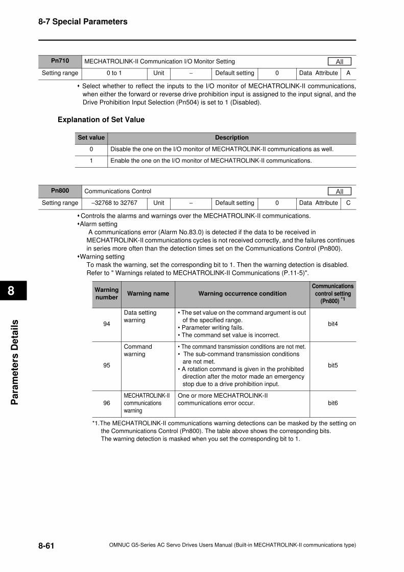
8-7 Special Parameters
8
Pa
ram
ete
rs D
eta
ils
Select whether to reflect the inputs to the I/O monitor of MECHATROLINK-II communications,
when either the forward or reverse drive prohibition input is assigned to the input signal, and the
Drive Prohibition Input Selection (Pn504) is set to 1 (Disabled).
Explanation of Set Value
Controls the alarms and warnings over the MECHATROLINK-II communications.
Alarm setting
A communications error (Alarm No.83.0) is detected if the data to be received in
MECHATROLINK-II communications cycles is not received correctly, and the failures continues
in series more often than the detection times set on the Communications Control (Pn800).
Warning setting
To mask the warning, set the corresponding bit to 1. Then the warning detection is disabled.
Refer to " Warnings related to MECHATROLINK-II Communications (P.11-5)".
Pn710 MECHATROLINK-II Communication I/O Monitor Setting
Setting range 0 to 1 Unit − Default setting 0 Data Attribute A
All
Set value Description
0 Disable the one on the I/O monitor of MECHATROLINK-II communications as well.
1 Enable the one on the I/O monitor of MECHATROLINK-II communications.
Pn800 Communications Control
Setting range −32768 to 32767 Unit − Default setting 0 Data Attribute C
All
Warning
numberWarning name Warning occurrence condition
Communications
control setting
(Pn800) *1
94
Data setting
warning
• The set value on the command argument is out
of the specified range.
• Parameter writing fails.
• The command set value is incorrect.
bit4
95
Command
warning
• The command transmission conditions are not met.
• The sub-command transmission conditions
are not met.
• A rotation command is given in the prohibited
direction after the motor made an emergency
stop due to a drive prohibition input.
bit5
96
MECHATROLINK-II
communications
warning
One or more MECHATROLINK-II
communications error occur. bit6
*1.The MECHATROLINK-II communications warning detections can be masked by the setting on
the Communications Control (Pn800). The table above shows the corresponding bits.
The warning detection is masked when you set the corresponding bit to 1.
8-61 OMNUC G5-Series AC Servo Drives Users Manual (Built-in MECHATROLINK-II communications type)
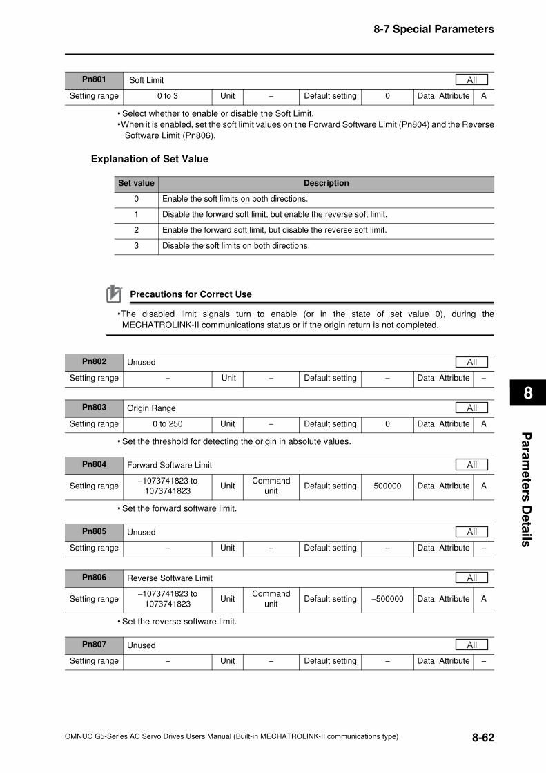
8-7 Special Parameters
8
Pa
ram
ete
rs D
eta
ils
Select whether to enable or disable the Soft Limit.
When it is enabled, set the soft limit values on the Forward Software Limit (Pn804) and the Reverse
Software Limit (Pn806).
Explanation of Set Value
Precautions for Correct Use
The disabled limit signals turn to enable (or in the state of set value 0), during the
MECHATROLINK-II communications status or if the origin return is not completed.
Set the threshold for detecting the origin in absolute values.
Set the forward software limit.
Set the reverse software limit.
Pn801 Soft Limit
Setting range 0 to 3 Unit − Default setting 0 Data Attribute A
All
Set value Description
0 Enable the soft limits on both directions.
1 Disable the forward soft limit, but enable the reverse soft limit.
2 Enable the forward soft limit, but disable the reverse soft limit.
3 Disable the soft limits on both directions.
Pn802 Unused
Setting range − Unit − Default setting − Data Attribute −
All
Pn803 Origin Range
Setting range 0 to 250 Unit − Default setting 0 Data Attribute A
All
Pn804 Forward Software Limit
Setting range−1073741823 to
1073741823Unit
Command
unitDefault setting 500000 Data Attribute A
All
Pn805 Unused
Setting range − Unit − Default setting − Data Attribute −
All
Pn806 Reverse Software Limit
Setting range−1073741823 to
1073741823Unit
Command
unitDefault setting −500000 Data Attribute A
All
Pn807 Unused
Setting range − Unit − Default setting − Data Attribute −
All
8-62OMNUC G5-Series AC Servo Drives Users Manual (Built-in MECHATROLINK-II communications type)
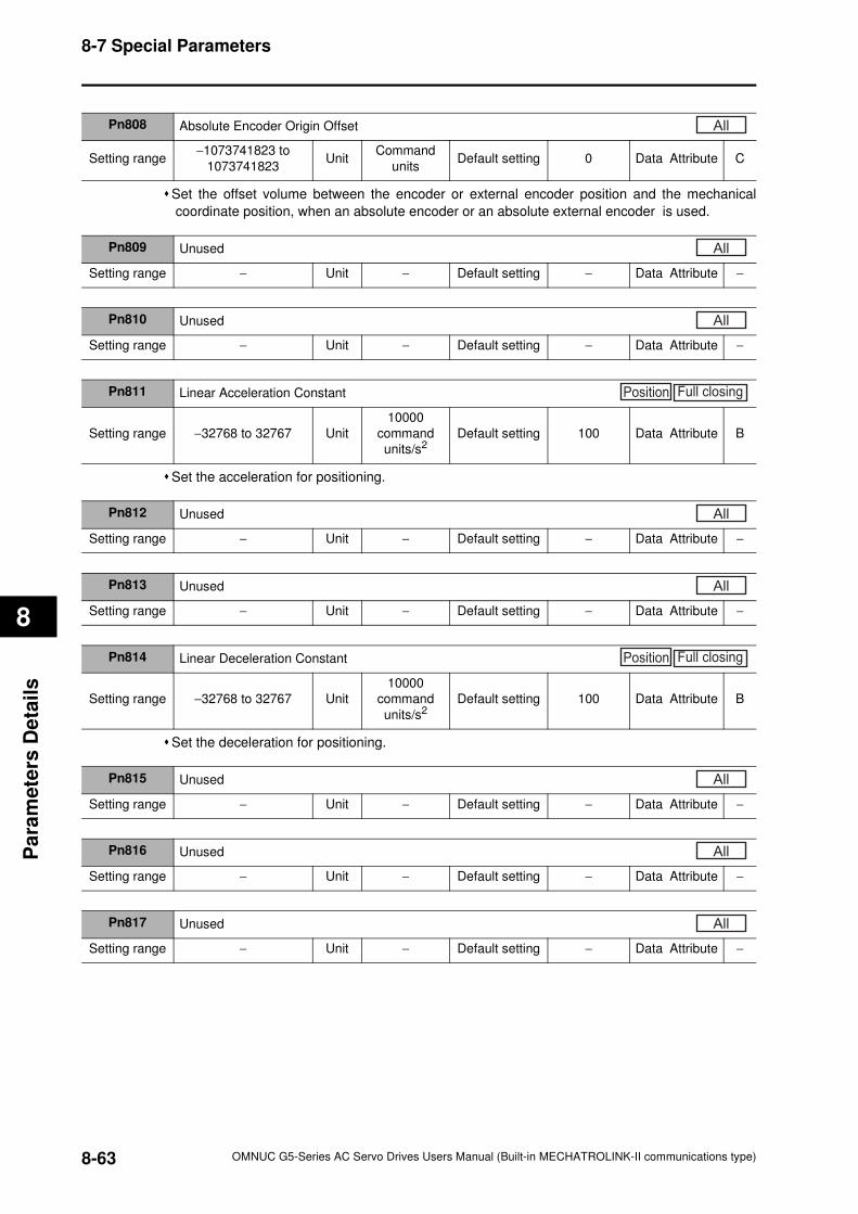
8-7 Special Parameters
8
Pa
ram
ete
rs D
eta
ils
Set the offset volume between the encoder or external encoder position and the mechanical
coordinate position, when an absolute encoder or an absolute external encoder is used.
Set the acceleration for positioning.
Set the deceleration for positioning.
Pn808 Absolute Encoder Origin Offset
Setting range−1073741823 to
1073741823Unit
Command
unitsDefault setting 0 Data Attribute C
All
Pn809 Unused
Setting range − Unit − Default setting − Data Attribute −
All
Pn810 Unused
Setting range − Unit − Default setting − Data Attribute −
All
Pn811 Linear Acceleration Constant
Setting range −32768 to 32767 Unit
10000
command
units/s2Default setting 100 Data Attribute B
Position Full closing
Pn812 Unused
Setting range − Unit − Default setting − Data Attribute −
All
Pn813 Unused
Setting range − Unit − Default setting − Data Attribute −
All
Pn814 Linear Deceleration Constant
Setting range −32768 to 32767 Unit
10000
command
units/s2Default setting 100 Data Attribute B
Position Full closing
Pn815 Unused
Setting range − Unit − Default setting − Data Attribute −
All
Pn816 Unused
Setting range − Unit − Default setting − Data Attribute −
All
Pn817 Unused
Setting range − Unit − Default setting − Data Attribute −
All
8-63 OMNUC G5-Series AC Servo Drives Users Manual (Built-in MECHATROLINK-II communications type)
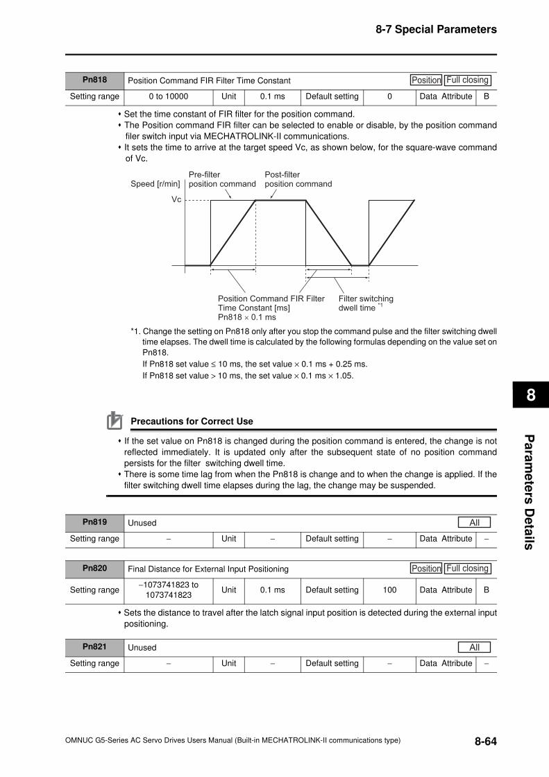
8-7 Special Parameters
8
Pa
ram
ete
rs D
eta
ils
Set the time constant of FIR filter for the position command.
The Position command FIR filter can be selected to enable or disable, by the position command
filer switch input via MECHATROLINK-II communications.
It sets the time to arrive at the target speed Vc, as shown below, for the square-wave command
of Vc.
*1. Change the setting on Pn818 only after you stop the command pulse and the filter switching dwell
time elapses. The dwell time is calculated by the following formulas depending on the value set on
Pn818.
If Pn818 set value ≤ 10 ms, the set value × 0.1 ms + 0.25 ms.
If Pn818 set value > 10 ms, the set value × 0.1 ms × 1.05.
Precautions for Correct Use
If the set value on Pn818 is changed during the position command is entered, the change is not
reflected immediately. It is updated only after the subsequent state of no position command
persists for the filter switching dwell time.
There is some time lag from when the Pn818 is change and to when the change is applied. If the
filter switching dwell time elapses during the lag, the change may be suspended.
Sets the distance to travel after the latch signal input position is detected during the external input
positioning.
Pn818 Position Command FIR Filter Time Constant
Setting range 0 to 10000 Unit 0.1 ms Default setting 0 Data Attribute B
Position Full closing
Speed [r/min]
Vc
Pre-filterposition command
Post-filterposition command
Position Command FIR FilterTime Constant [ms]Pn818 × 0.1 ms
Filter switchingdwell time *1
Pn819 Unused
Setting range − Unit − Default setting − Data Attribute −
All
Pn820 Final Distance for External Input Positioning
Setting range−1073741823 to
1073741823Unit 0.1 ms Default setting 100 Data Attribute B
Position Full closing
Pn821 Unused
Setting range − Unit − Default setting − Data Attribute −
All
8-64OMNUC G5-Series AC Servo Drives Users Manual (Built-in MECHATROLINK-II communications type)
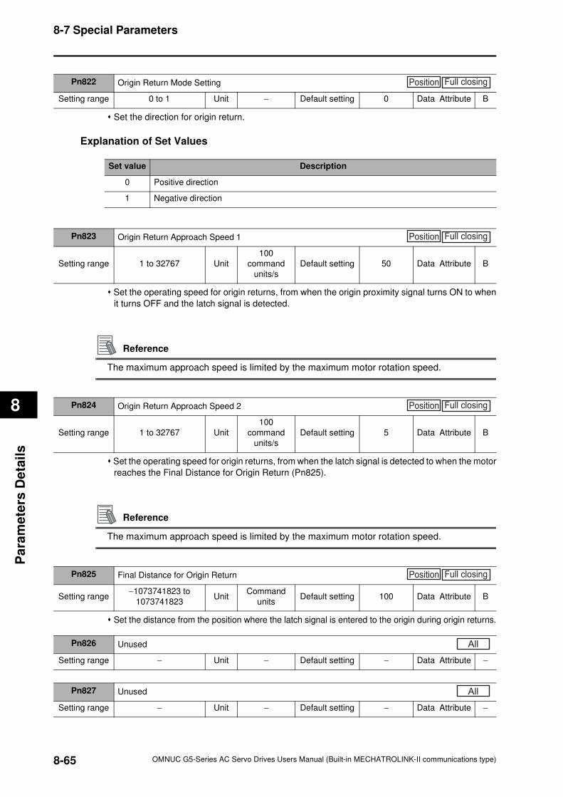
8-7 Special Parameters
8
Pa
ram
ete
rs D
eta
ils
Set the direction for origin return.
Explanation of Set Values
Set the operating speed for origin returns, from when the origin proximity signal turns ON to when
it turns OFF and the latch signal is detected.
Reference
The maximum approach speed is limited by the maximum motor rotation speed.
Set the operating speed for origin returns, from when the latch signal is detected to when the motor
reaches the Final Distance for Origin Return (Pn825).
Reference
The maximum approach speed is limited by the maximum motor rotation speed.
Set the distance from the position where the latch signal is entered to the origin during origin returns.
Pn822 Origin Return Mode Setting
Setting range 0 to 1 Unit − Default setting 0 Data Attribute B
Position Full closing
Set value Description
0 Positive direction
1 Negative direction
Pn823 Origin Return Approach Speed 1
Setting range 1 to 32767 Unit
100
command
units/s
Default setting 50 Data Attribute B
Position Full closing
Pn824 Origin Return Approach Speed 2
Setting range 1 to 32767 Unit
100
command
units/s
Default setting 5 Data Attribute B
Position Full closing
Pn825 Final Distance for Origin Return
Setting range−1073741823 to
1073741823Unit
Command
unitsDefault setting 100 Data Attribute B
Position Full closing
Pn826 Unused
Setting range − Unit − Default setting − Data Attribute −
All
Pn827 Unused
Setting range − Unit − Default setting − Data Attribute −
All
8-65 OMNUC G5-Series AC Servo Drives Users Manual (Built-in MECHATROLINK-II communications type)
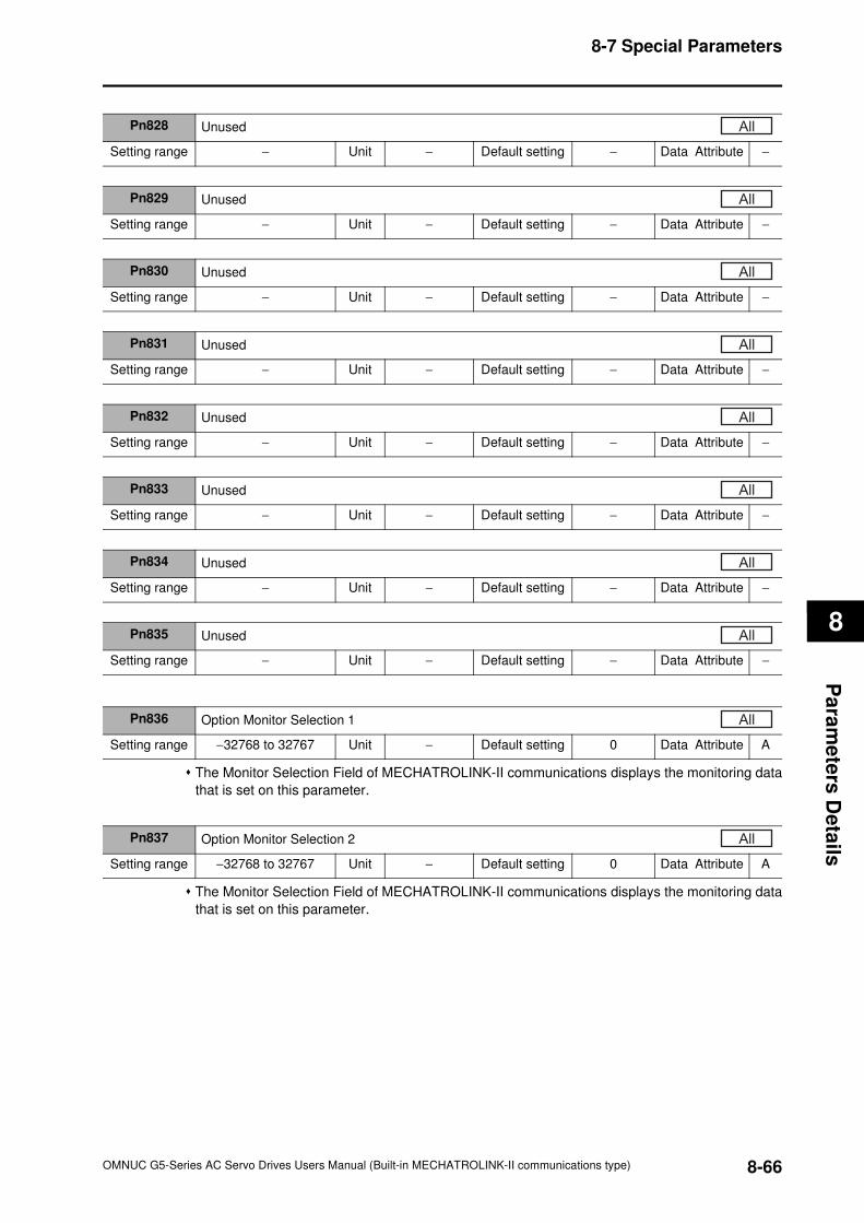
8-7 Special Parameters
8
Pa
ram
ete
rs D
eta
ils
The Monitor Selection Field of MECHATROLINK-II communications displays the monitoring data
that is set on this parameter.
The Monitor Selection Field of MECHATROLINK-II communications displays the monitoring data
that is set on this parameter.
Pn828 Unused
Setting range − Unit − Default setting − Data Attribute −
All
Pn829 Unused
Setting range − Unit − Default setting − Data Attribute −
All
Pn830 Unused
Setting range − Unit − Default setting − Data Attribute −
All
Pn831 Unused
Setting range − Unit − Default setting − Data Attribute −
All
Pn832 Unused
Setting range − Unit − Default setting − Data Attribute −
All
Pn833 Unused
Setting range − Unit − Default setting − Data Attribute −
All
Pn834 Unused
Setting range − Unit − Default setting − Data Attribute −
All
Pn835 Unused
Setting range − Unit − Default setting − Data Attribute −
All
Pn836 Option Monitor Selection 1
Setting range −32768 to 32767 Unit − Default setting 0 Data Attribute A
All
Pn837 Option Monitor Selection 2
Setting range −32768 to 32767 Unit − Default setting 0 Data Attribute A
All
8-66OMNUC G5-Series AC Servo Drives Users Manual (Built-in MECHATROLINK-II communications type)

OMNUC G5-Series AC Servo Drives Users Manual (Built-in MECHATROLINK-II communications type)
9
9
AccuraxAccurax
This chapter explains the operating procedures and how to operate in each mode.
9-1 Operational Procedure .................................................9-1
9-2 Preparing for Operation ...............................................9-2
9-3 Trial Operation ..............................................................9-7
Operation
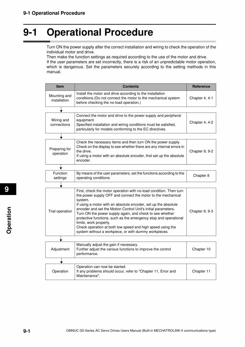
9-1
9-1 Operational Procedure
OMNUC G5-Series AC Servo Drives Users Manual (Built-in MECHATROLINK-II communications type)
9
Op
era
tio
n
9-1 Operational Procedure
Turn ON the power supply after the correct installation and wiring to check the operation of the
individual motor and drive.
Then make the function settings as required according to the use of the motor and drive.
If the user parameters are set incorrectly, there is a risk of an unpredictable motor operation,
which is dangerous. Set the parameters securely according to the setting methods in this
manual.
Item Contents Reference
Mounting and
installation
Install the motor and drive according to the installation
conditions.(Do not connect the motor to the mechanical system
before checking the no-load operation.)
Chapter 4, 4-1
Wiring and
connections
Connect the motor and drive to the power supply and peripheral
equipment.
Specified installation and wiring conditions must be satisfied,
particularly for models conforming to the EC directives.
Chapter 4, 4-2
Preparing for
operation
Check the necessary items and then turn ON the power supply.
Check on the display to see whether there are any internal errors in
the drive.
If using a motor with an absolute encoder, first set up the absolute
encoder.
Chapter 9, 9-2
Function
settings
By means of the user parameters, set the functions according to the
operating conditions.Chapter 8
Trial operation
First, check the motor operation with no-load condition. Then turn
the power supply OFF and connect the motor to the mechanical
system.
If using a motor with an absolute encoder, set up the absolute
encoder and set the Motion Control Unit's initial parameters.
Turn ON the power supply again, and check to see whether
protective functions, such as the emergency stop and operational
limits, work properly.
Check operation at both low speed and high speed using the
system without a workpiece, or with dummy workpieces.
Chapter 9, 9-3
Adjustment
Manually adjust the gain if necessary.
Further adjust the various functions to improve the control
performance.
Chapter 10
Operation
Operation can now be started.
If any problems should occur, refer to "Chapter 11, Error and
Maintenance".
Chapter 11
9-2
9-2 Preparing for Operation
OMNUC G5-Series AC Servo Drives Users Manual (Built-in MECHATROLINK-II communications type)
9
Op
era
tion
9-2 Preparing for Operation
This section explains the procedure to prepare the mechanical system for operation following
installation and wiring of the motor and drive. It explains items to check both before and after
turning ON the power supply.
It also explains the setup procedure required if using a motor with an absolute encoder.
Items to Check Before Turning ON the Power Supply
Checking Power Supply Voltage
Check to be sure that the power supply voltage is within the ranges shown below.
R88D-KNA5L-ML2/-KN01L-ML2/-KN02L-ML2/-KN04L-ML2 (Single-phase 100-VAC input)
Main circuit power supply: Single-phase 100 to 120 VAC (85 to 132) 50/60 Hz
Control circuit power supply: Single-phase 100 to 120 VAC (85 to 132) 50/60 Hz
R88D-KN01H-ML2/-KN02H-ML2/-KN04H-ML2/-KN08H-ML2/-KN10H-ML2/-KN15H-ML2
Main circuit power supply: Single-phase or single-phase/3-phase 200 to 240 V (170 to 264 V)
50/60 Hz Control circuit power supply: Single-phase 200 to 240 VAC (170 to 264 V) 50/60 Hz
R88D-KN20H-ML2/-KN30H-ML2/-KN50H-ML2 (3-phase 200-VAC input)
Main circuit power supply: 3-phase 200 to 230 VAC (170 to 253 V)
50/60 Hz Control circuit power supply: Single-phase 200 to 230 VAC (170 to 253 V) 50/60 Hz
R88D-KN06F-ML2/-KN10F-ML2/-KN15F-ML2/-KN20F-ML2/-KN30F-ML2/-KN50F-ML2
Main circuit power supply: 3-phase 380 to 480 VAC (323 to 528 V)
50/60 Hz Control circuit power supply: 24 VDC ± 15%
Checking Terminal Block Wiring
The main circuit power supply inputs (L1/L3 or L1/L2/L3) must be properly connected to the
terminal block.
The control circuit power supply inputs (L1C/L2C) must be properly connected to the terminal
block.
The motor's red (U), white (V), and blue (W) power lines and the green/yellow ( ) must be
properly connected to the terminal block.
Checking the Motor
There should be no load on the motor. (Do not connect the mechanical system.)
The motor side power lines and the power cables must be securely connected.
Checking the Encoder Wiring
The encoder cable must be securely connected to the encoder connector (CN2) at the drive side.
The encoder cable must be securely connected to the encoder connector at the motor side.
Checking the MECHATROLINK-II Communications Connectors
The MECHATROLINK-II Communications Cables must be connected securely to the
MECHATROLINK-II Communications Connectors (ML2A and ML2B).
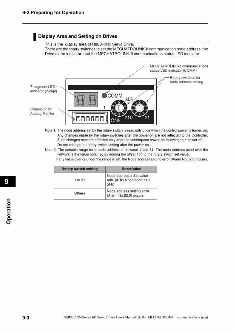
9-3
9-2 Preparing for Operation
OMNUC G5-Series AC Servo Drives Users Manual (Built-in MECHATROLINK-II communications type)
9
Op
era
tio
n
Display Area and Setting on Drives
This is the display area of R88D-KNx Servo Drive.
There are the rotary switches to set the MECHATROLINK-II communication node address, the
Drive alarm indicator, and the MECHATROLINK-II communications status LED indicator.
Note 1. The node address set by the rotary switch is read only once when the control power is turned on.
Any changes made by the rotary switches after the power-on are not reflected to the Controller.
Such changes become effective only after the subsequent power-on following to a power-off.
Do not change the rotary switch setting after the power-on.
Note 2. The settable range for a node address is between 1 and 31. The node address used over the
network is the value obtained by adding the offset 40h to the rotary switch set value.
If any value over or under the range is set, the Node address setting error (Alarm No.82.0) occurs.
MECHATROLINK-II communications
status LED indicator (COMM)
Rotary switches for
node address setting
Connector for
Analog Monitor
7-segment LED
indicator (2-digit)
ADRCOMM
Rotary switch setting Description
1 to 31
Node address = Set value +
40h (41h≤ Node address ≤
5Fh)
OthersNode address setting error
(Alarm No.82.0) occurs.
9-4
9-2 Preparing for Operation
OMNUC G5-Series AC Servo Drives Users Manual (Built-in MECHATROLINK-II communications type)
9
Op
era
tion
MECHATROLINK-II Communications Status LED Indicator
The table below shows the LED indication status and the corresponding conditions of the
communications.
Note. If any of communication related error occurs while an error that is not related to MECHATROLINK-
II communications happens, the MECHATROLINK-II Communications Status LED Indicator
follows the corresponding communications status as shown above.
Turning on the Power Supply
Turn on the control circuit power after you conduct the pre-power-on checking.
You may turn on the main circuit power, but it is not a requisite.
It takes approx 2 seconds for the alarm output (/ALM) to turn on since the power-on. Do not
attempt to detect an alarm, during this period, by the Host Controller. This precaution relates to
the case when the power is turned on while the Host Controller is connected.
LED status Communications status
Unlit No communication is established.
Green Flash Asynchronous communications is established.
Green Light Synchronous communications is established.
Red Flash
A clearable error occurred in MECHATROLINK-II communications.
• Communications error (Alarm No.83.0)
• Transmission cycle error (Alarm No.84.0)
• SSYNC_SET error (Alarm No.84.4)
• Watchdog data error (Alarm No.86.0)
• Transmission cycle setting error (Alarm No.90.0)
• CONNECT error (Alarm No.90.1)
• SYNC command error (Alarm No.91.0)
Red Light
A non-clearable error occurred in MECHATROLINK-II communications.
• Node address setting error (Alarm No.82.0)
• SYNC process error (Alarm No.84.3)
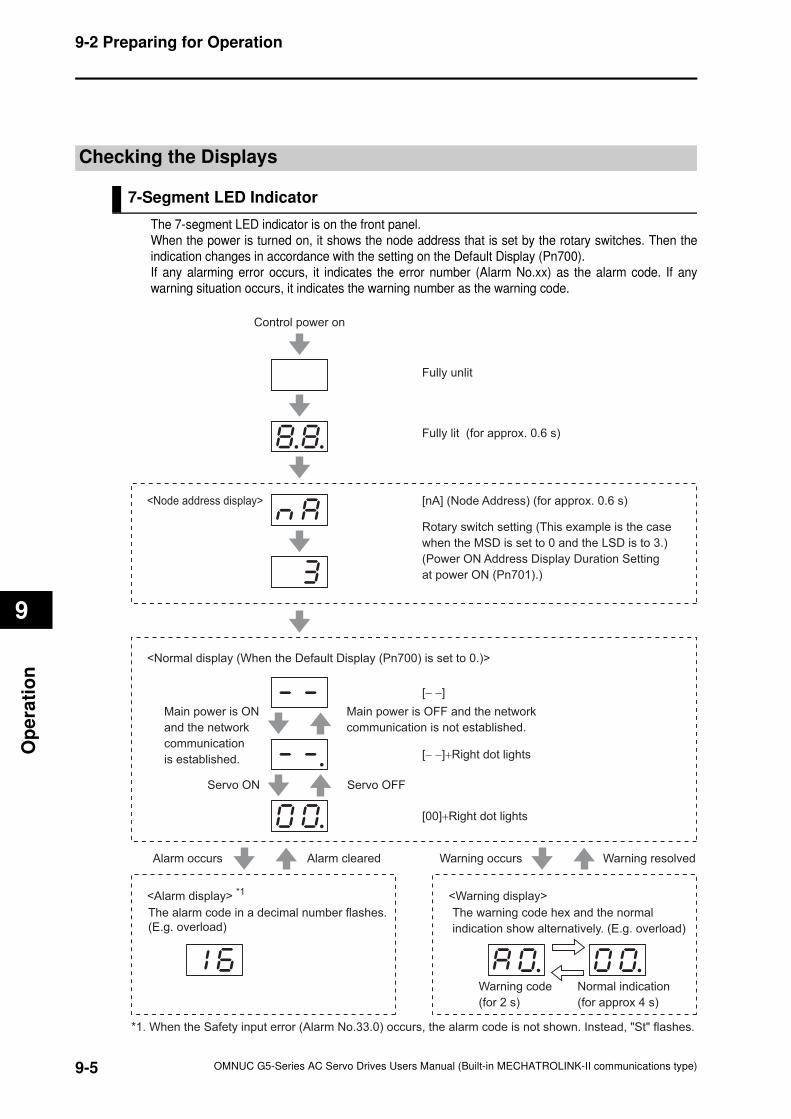
9-5
9-2 Preparing for Operation
OMNUC G5-Series AC Servo Drives Users Manual (Built-in MECHATROLINK-II communications type)
9
Op
era
tio
n
Checking the Displays
7-Segment LED Indicator
The 7-segment LED indicator is on the front panel.
When the power is turned on, it shows the node address that is set by the rotary switches. Then the
indication changes in accordance with the setting on the Default Display (Pn700).
If any alarming error occurs, it indicates the error number (Alarm No.xx) as the alarm code. If any
warning situation occurs, it indicates the warning number as the warning code.
*1. When the Safety input error (Alarm No.33.0) occurs, the alarm code is not shown. Instead, "St" flashes.
Warning occurs Warning resolved
Control power on
Main power is ON
and the network
communication
is established.
Main power is OFF and the network
communication is not established.
Servo ON Servo OFF
[− −]
Fully unlit
Fully lit (for approx. 0.6 s)
[nA] (Node Address) (for approx. 0.6 s)
Rotary switch setting (This example is the case
when the MSD is set to 0 and the LSD is to 3.)
(Power ON Address Display Duration Setting
at power ON (Pn701).)
[− −]+Right dot lights
[00]+Right dot lights
Alarm occurs Alarm cleared
Warning code
(for 2 s)
Normal indication
(for approx 4 s)
<Alarm display> *1
<Normal display (When the Default Display (Pn700) is set to 0.)>
<Node address display>
The alarm code in a decimal number flashes.
(E.g. overload)
<Warning display>
The warning code hex and the normal
indication show alternatively. (E.g. overload)
9-6
9-2 Preparing for Operation
OMNUC G5-Series AC Servo Drives Users Manual (Built-in MECHATROLINK-II communications type)
9
Op
era
tion
Absolute Encoder Setup
You must set up the absolute encoder if using a motor with an absolute encoder. The setup is
required when you turn ON the power supply for the first time, when an absolute encoder
system down error (Alarm No.40) occurs, or when the encoder cable is disconnected and then
connected again.
To use an absolute encoder, set the Operation Switch when Using Absolute Encoder (Pn015)
to 0 or 2.
The absolute encoder is set up via communications. Refer to the operation manual of the host
controller of CX-Drive (Cat. No. W453).
After the setup, turn off the control power and turn it on again.
ABS
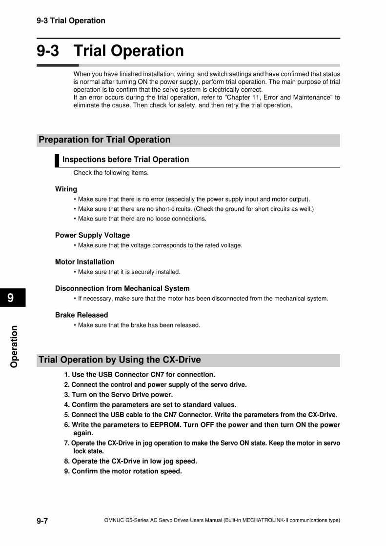
9-7
9-3 Trial Operation
OMNUC G5-Series AC Servo Drives Users Manual (Built-in MECHATROLINK-II communications type)
9
Op
era
tio
n
9-3 Trial Operation
When you have finished installation, wiring, and switch settings and have confirmed that status
is normal after turning ON the power supply, perform trial operation. The main purpose of trial
operation is to confirm that the servo system is electrically correct.
If an error occurs during the trial operation, refer to "Chapter 11, Error and Maintenance" to
eliminate the cause. Then check for safety, and then retry the trial operation.
Preparation for Trial Operation
Inspections before Trial Operation
Check the following items.
Wiring
Make sure that there is no error (especially the power supply input and motor output).
Make sure that there are no short-circuits. (Check the ground for short circuits as well.)
Make sure that there are no loose connections.
Power Supply Voltage
Make sure that the voltage corresponds to the rated voltage.
Motor Installation
Make sure that it is securely installed.
Disconnection from Mechanical System
If necessary, make sure that the motor has been disconnected from the mechanical system.
Brake Released
Make sure that the brake has been released.
Trial Operation by Using the CX-Drive
1. Use the USB Connector CN7 for connection.
2. Connect the control and power supply of the servo drive.
3. Turn on the Servo Drive power.
4. Confirm the parameters are set to standard values.
5. Connect the USB cable to the CN7 Connector. Write the parameters from the CX-Drive.
6. Write the parameters to EEPROM. Turn OFF the power and then turn ON the power
again.
7. Operate the CX-Drive in jog operation to make the Servo ON state. Keep the motor in servolock state.
8. Operate the CX-Drive in low jog speed.
9. Confirm the motor rotation speed.
OMNUC G5-Series AC Servo Drives Users Manual (Built-in MECHATROLINK-II communications type)
10
10
Accurax
This chapter explains the functions, setting methods and items to note regarding
various gain adjustments.
10-1 Analog Monitor ...........................................................10-1
10-2 Gain Adjustment .........................................................10-4
10-3 Realtime Autotuning...................................................10-6
10-4 Manual Tuning ..........................................................10-13
10-5 Anti-vibration Control...............................................10-21
10-6 Adaptive Filter...........................................................10-25
10-7 Notch Filter................................................................10-28
10-8 Disturbance Observer Function ..............................10-31
10-9 Friction Torque Compensation Function ...............10-33
10-10Hybrid Vibration Suppression Function ................10-35
10-11Feed-forward Function ............................................10-36
10-12Instantaneous Speed Observer Function..............10-39
Adjustment Functions
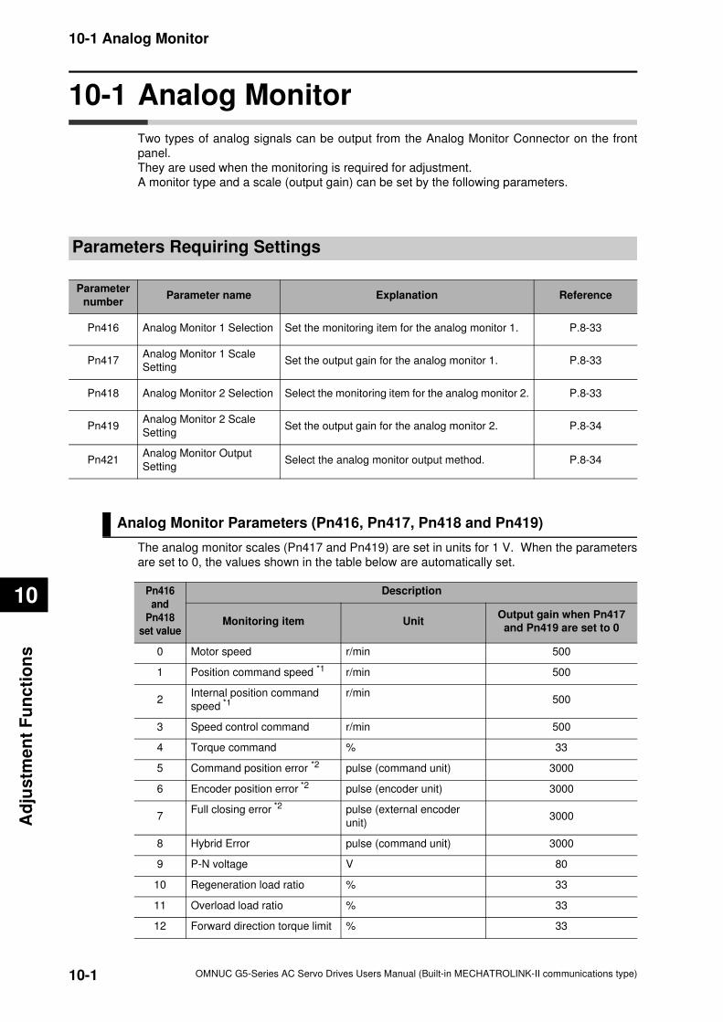
10-1
10-1 Analog Monitor
OMNUC G5-Series AC Servo Drives Users Manual (Built-in MECHATROLINK-II communications type)
10
Ad
justm
en
t F
un
cti
on
s
10-1 Analog Monitor
Two types of analog signals can be output from the Analog Monitor Connector on the front
panel.
They are used when the monitoring is required for adjustment.
A monitor type and a scale (output gain) can be set by the following parameters.
Parameters Requiring Settings
Analog Monitor Parameters (Pn416, Pn417, Pn418 and Pn419)
The analog monitor scales (Pn417 and Pn419) are set in units for 1 V. When the parameters
are set to 0, the values shown in the table below are automatically set.
Parameter
numberParameter name Explanation Reference
Pn416 Analog Monitor 1 Selection Set the monitoring item for the analog monitor 1. P.8-33
Pn417Analog Monitor 1 Scale
SettingSet the output gain for the analog monitor 1. P.8-33
Pn418 Analog Monitor 2 Selection Select the monitoring item for the analog monitor 2. P.8-33
Pn419Analog Monitor 2 Scale
SettingSet the output gain for the analog monitor 2. P.8-34
Pn421Analog Monitor Output
SettingSelect the analog monitor output method. P.8-34
Pn416
and
Pn418
set value
Description
Monitoring item UnitOutput gain when Pn417
and Pn419 are set to 0
0 Motor speed r/min 500
1 Position command speed *1 r/min 500
2Internal position command
speed *1r/min
500
3 Speed control command r/min 500
4 Torque command % 33
5 Command position error *2 pulse (command unit) 3000
6 Encoder position error *2 pulse (encoder unit) 3000
7Full closing error *2 pulse (external encoder
unit)3000
8 Hybrid Error pulse (command unit) 3000
9 P-N voltage V 80
10 Regeneration load ratio % 33
11 Overload load ratio % 33
12 Forward direction torque limit % 33
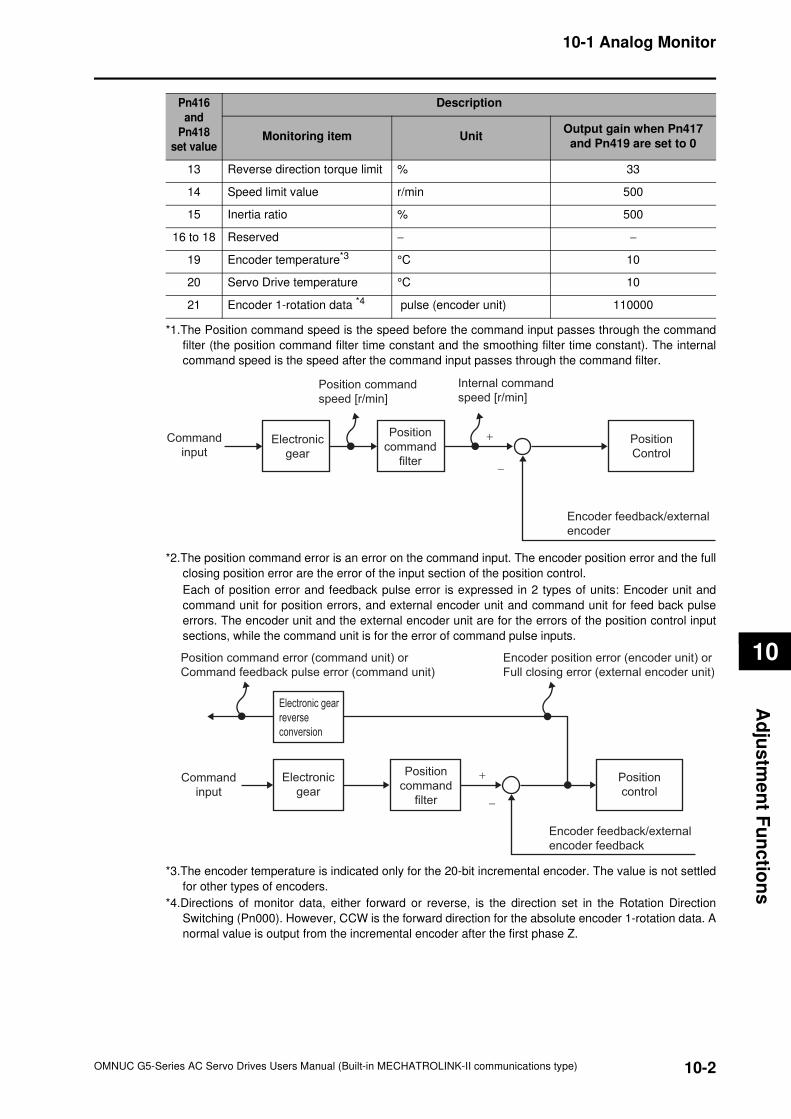
10-2
10-1 Analog Monitor
OMNUC G5-Series AC Servo Drives Users Manual (Built-in MECHATROLINK-II communications type)
10
Ad
jus
tme
nt F
un
ctio
ns
13 Reverse direction torque limit % 33
14 Speed limit value r/min 500
15 Inertia ratio % 500
16 to 18 Reserved − −
19 Encoder temperature*3°C 10
20 Servo Drive temperature °C 10
21 Encoder 1-rotation data *4 pulse (encoder unit) 110000
*1.The Position command speed is the speed before the command input passes through the command
filter (the position command filter time constant and the smoothing filter time constant). The internal
command speed is the speed after the command input passes through the command filter.
*2.The position command error is an error on the command input. The encoder position error and the full
closing position error are the error of the input section of the position control.
Each of position error and feedback pulse error is expressed in 2 types of units: Encoder unit and
command unit for position errors, and external encoder unit and command unit for feed back pulse
errors. The encoder unit and the external encoder unit are for the errors of the position control input
sections, while the command unit is for the error of command pulse inputs.
*3.The encoder temperature is indicated only for the 20-bit incremental encoder. The value is not settled
for other types of encoders.
*4.Directions of monitor data, either forward or reverse, is the direction set in the Rotation Direction
Switching (Pn000). However, CCW is the forward direction for the absolute encoder 1-rotation data. A
normal value is output from the incremental encoder after the first phase Z.
Pn416
and
Pn418
set value
Description
Monitoring item UnitOutput gain when Pn417
and Pn419 are set to 0
Command
inputElectronic
gear
Position command
speed [r/min]
Internal command
speed [r/min]
+
−
Position
command
filter
Position
Control
Encoder feedback/external
encoder
Command
input
Electronic
gear
Encoder position error (encoder unit) or
Full closing error (external encoder unit)
+
−
Position
command
filter
Position
control
Encoder feedback/external
encoder feedback
Position command error (command unit) or
Command feedback pulse error (command unit)
Electronic gear
reverse
conversion
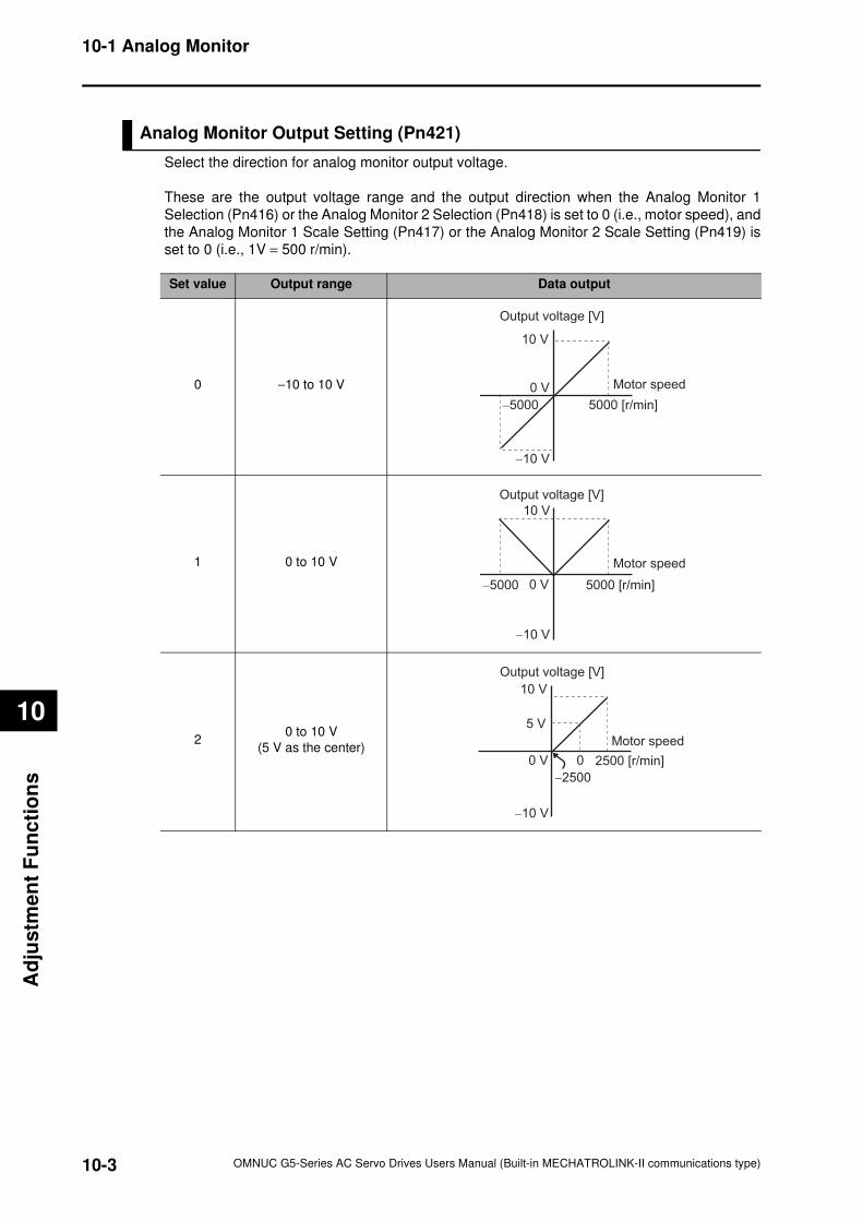
10-3
10-1 Analog Monitor
OMNUC G5-Series AC Servo Drives Users Manual (Built-in MECHATROLINK-II communications type)
10
Ad
justm
en
t F
un
cti
on
s
Analog Monitor Output Setting (Pn421)
Select the direction for analog monitor output voltage.
These are the output voltage range and the output direction when the Analog Monitor 1
Selection (Pn416) or the Analog Monitor 2 Selection (Pn418) is set to 0 (i.e., motor speed), and
the Analog Monitor 1 Scale Setting (Pn417) or the Analog Monitor 2 Scale Setting (Pn419) is
set to 0 (i.e., 1V = 500 r/min).
Set value Output range Data output
0 −10 to 10 V
1 0 to 10 V
20 to 10 V
(5 V as the center)
10 V
−10 V
0 V
−5000 5000 [r/min]
Motor speed
Output voltage [V]
10 V
−10 V
0 V−5000 5000 [r/min]
Motor speed
Output voltage [V]
10 V
5 V
−10 V
0 V 0
−2500
2500 [r/min]
Motor speed
Output voltage [V]
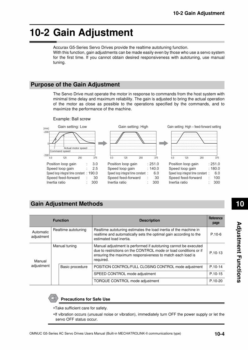
10-4
10-2 Gain Adjustment
OMNUC G5-Series AC Servo Drives Users Manual (Built-in MECHATROLINK-II communications type)
10
Ad
jus
tme
nt F
un
ctio
ns
10-2 Gain Adjustment
Accurax G5-Series Servo Drives provide the realtime autotuning function.
With this function, gain adjustments can be made easily even by those who use a servo system
for the first time. If you cannot obtain desired responsiveness with autotuning, use manual
tuning.
Purpose of the Gain Adjustment
The Servo Drive must operate the motor in response to commands from the host system with
minimal time delay and maximum reliability. The gain is adjusted to bring the actual operation
of the motor as close as possible to the operations specified by the commands, and to
maximize the performance of the machine.
Example: Ball screw
Gain Adjustment Methods
Precautions for Safe Use
Take sufficient care for safety.
If vibration occurs (unusual noise or vibration), immediately turn OFF the power supply or let the
servo OFF status occur.
3.0
2.5
190.0
30
300
251.0
140.0
6.0
30
300
0
0.0 375250125 0.0 375250125 0.0 375250125
251.0
180.0
6.0
100
300
Gain setting: Low Gain setting: High Gain setting: High + feed-forward setting[r/min]
Command speedActual motor speed
Position loop gain :
Speed loop gain :
Speed loop integral time constant :
Speed feed-forward :
Inertia ratio :
Position loop gain :
Speed loop gain :
Speed loop integral time constant :
Speed feed-forward :
Inertia ratio :
Position loop gain :
Speed loop gain :
Speed loop integral time constant :
Speed feed-forward :
Inertia ratio :
+2000
−2000
Function DescriptionReference
page
Automatic
adjustment
Realtime autotuning Realtime autotuning estimates the load inertia of the machine in
realtime and automatically sets the optimal gain according to the
estimated load inertia.
P.10-6
Manual
adjustment
Manual tuning Manual adjustment is performed if autotuning cannot be executed
due to restrictions on the CONTROL mode or load conditions or if
ensuring the maximum responsiveness to match each load is
required.
P.10-13
Basic procedure POSITION CONTROL/FULL CLOSING CONTROL mode adjustment P.10-14
SPEED CONTROL mode adjustment P.10-15
TORQUE CONTROL mode adjustment P.10-20
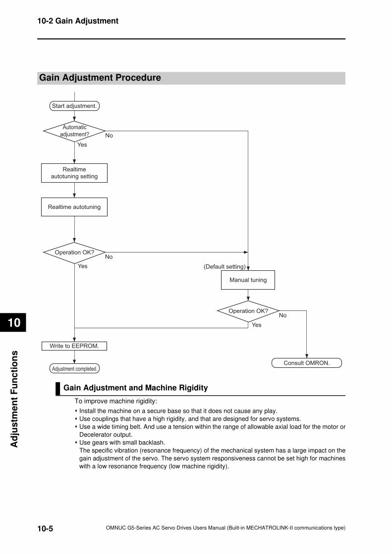
10-5
10-2 Gain Adjustment
OMNUC G5-Series AC Servo Drives Users Manual (Built-in MECHATROLINK-II communications type)
10
Ad
justm
en
t F
un
cti
on
s
Gain Adjustment Procedure
Gain Adjustment and Machine Rigidity
To improve machine rigidity:
Install the machine on a secure base so that it does not cause any play.
Use couplings that have a high rigidity, and that are designed for servo systems.
Use a wide timing belt. And use a tension within the range of allowable axial load for the motor or
Decelerator output.
Use gears with small backlash.
The specific vibration (resonance frequency) of the mechanical system has a large impact on the
gain adjustment of the servo. The servo system responsiveness cannot be set high for machines
with a low resonance frequency (low machine rigidity).
Start adjustment.
Automatic
adjustment?
Operation OK?
Yes
Yes
NoOperation OK?
Yes
No
No
Realtime autotuning
Realtime
autotuning setting
Manual tuning
Adjustment completed.
Write to EEPROM.
Consult OMRON.
(Default setting)
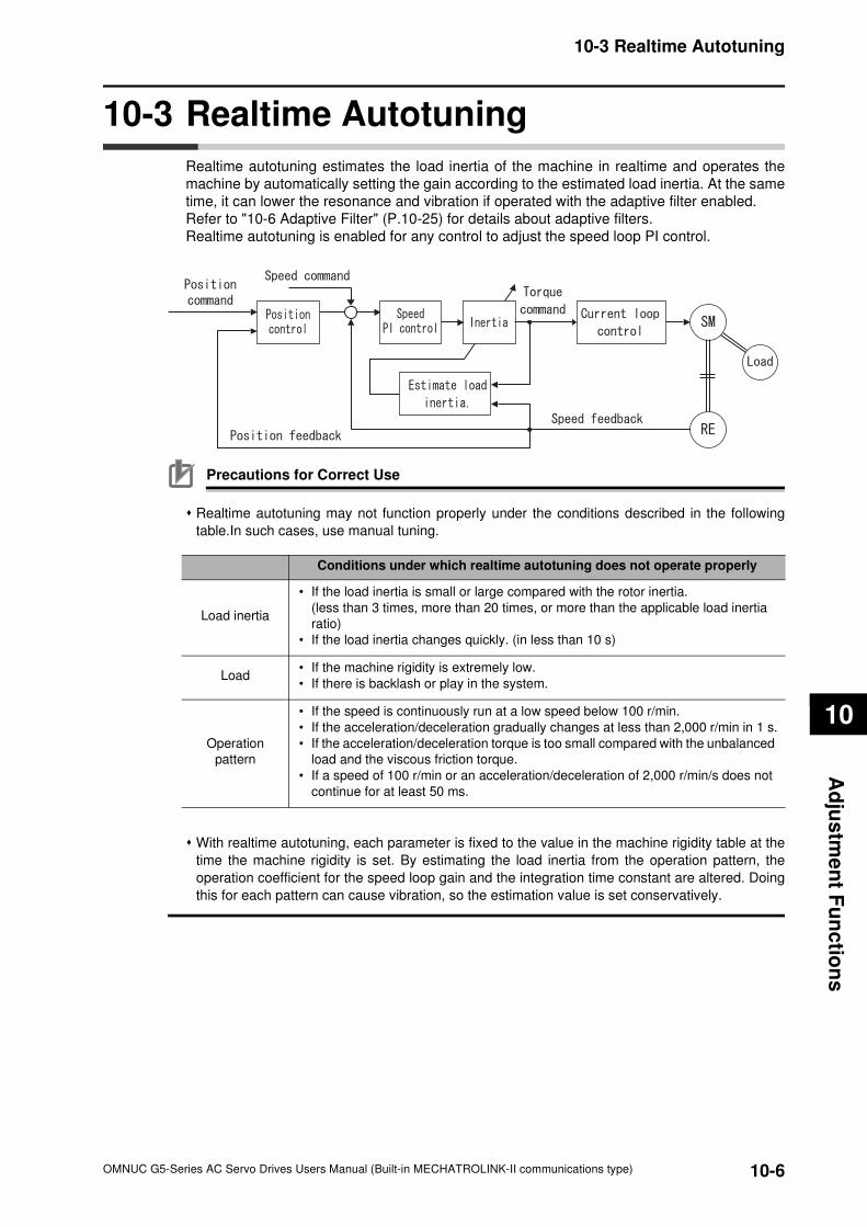
10-6
10-3 Realtime Autotuning
OMNUC G5-Series AC Servo Drives Users Manual (Built-in MECHATROLINK-II communications type)
10
Ad
jus
tme
nt F
un
ctio
ns
10-3 Realtime Autotuning
Realtime autotuning estimates the load inertia of the machine in realtime and operates the
machine by automatically setting the gain according to the estimated load inertia. At the same
time, it can lower the resonance and vibration if operated with the adaptive filter enabled.
Refer to "10-6 Adaptive Filter" (P.10-25) for details about adaptive filters.
Realtime autotuning is enabled for any control to adjust the speed loop PI control.
Precautions for Correct Use
Realtime autotuning may not function properly under the conditions described in the following
table.In such cases, use manual tuning.
With realtime autotuning, each parameter is fixed to the value in the machine rigidity table at the
time the machine rigidity is set. By estimating the load inertia from the operation pattern, the
operation coefficient for the speed loop gain and the integration time constant are altered. Doing
this for each pattern can cause vibration, so the estimation value is set conservatively.
Conditions under which realtime autotuning does not operate properly
Load inertia
• If the load inertia is small or large compared with the rotor inertia.
(less than 3 times, more than 20 times, or more than the applicable load inertia
ratio)
• If the load inertia changes quickly. (in less than 10 s)
Load• If the machine rigidity is extremely low.
• If there is backlash or play in the system.
Operation
pattern
• If the speed is continuously run at a low speed below 100 r/min.
• If the acceleration/deceleration gradually changes at less than 2,000 r/min in 1 s.
• If the acceleration/deceleration torque is too small compared with the unbalanced
load and the viscous friction torque.
• If a speed of 100 r/min or an acceleration/deceleration of 2,000 r/min/s does not
continue for at least 50 ms.
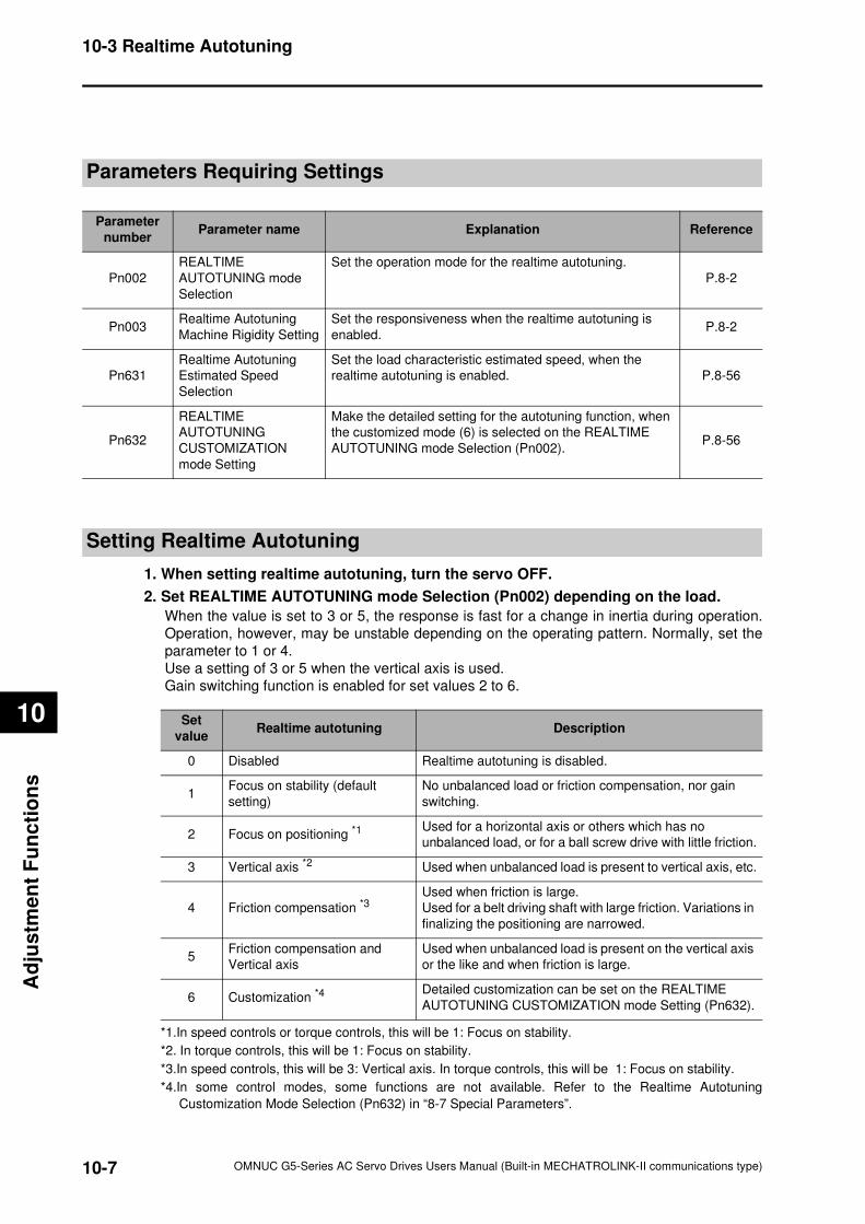
10-7
10-3 Realtime Autotuning
OMNUC G5-Series AC Servo Drives Users Manual (Built-in MECHATROLINK-II communications type)
10
Ad
justm
en
t F
un
cti
on
s
Parameters Requiring Settings
Setting Realtime Autotuning
1. When setting realtime autotuning, turn the servo OFF.
2. Set REALTIME AUTOTUNING mode Selection (Pn002) depending on the load.
When the value is set to 3 or 5, the response is fast for a change in inertia during operation.
Operation, however, may be unstable depending on the operating pattern. Normally, set the
parameter to 1 or 4.
Use a setting of 3 or 5 when the vertical axis is used.
Gain switching function is enabled for set values 2 to 6.
Parameter
numberParameter name Explanation Reference
Pn002
REALTIME
AUTOTUNING mode
Selection
Set the operation mode for the realtime autotuning.
P.8-2
Pn003Realtime Autotuning
Machine Rigidity Setting
Set the responsiveness when the realtime autotuning is
enabled.P.8-2
Pn631
Realtime Autotuning
Estimated Speed
Selection
Set the load characteristic estimated speed, when the
realtime autotuning is enabled. P.8-56
Pn632
REALTIME
AUTOTUNING
CUSTOMIZATION
mode Setting
Make the detailed setting for the autotuning function, when
the customized mode (6) is selected on the REALTIME
AUTOTUNING mode Selection (Pn002).P.8-56
Set
valueRealtime autotuning Description
0 Disabled Realtime autotuning is disabled.
1Focus on stability (default
setting)
No unbalanced load or friction compensation, nor gain
switching.
2 Focus on positioning *1Used for a horizontal axis or others which has no
unbalanced load, or for a ball screw drive with little friction.
3 Vertical axis *2 Used when unbalanced load is present to vertical axis, etc.
4 Friction compensation *3Used when friction is large.
Used for a belt driving shaft with large friction. Variations in
finalizing the positioning are narrowed.
5Friction compensation and
Vertical axis
Used when unbalanced load is present on the vertical axis
or the like and when friction is large.
6 Customization *4Detailed customization can be set on the REALTIME
AUTOTUNING CUSTOMIZATION mode Setting (Pn632).
*1.In speed controls or torque controls, this will be 1: Focus on stability.
*2. In torque controls, this will be 1: Focus on stability.
*3.In speed controls, this will be 3: Vertical axis. In torque controls, this will be 1: Focus on stability.
*4.In some control modes, some functions are not available. Refer to the Realtime Autotuning
Customization Mode Selection (Pn632) in “8-7 Special Parameters”.
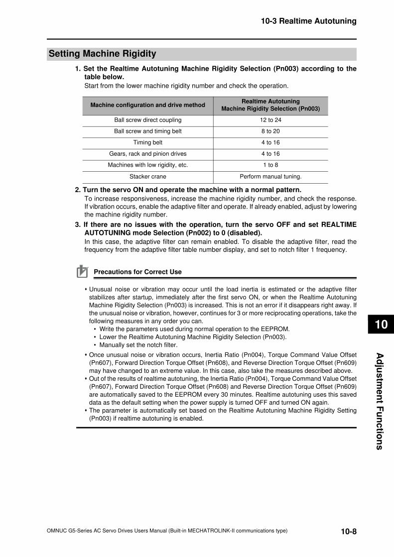
10-8
10-3 Realtime Autotuning
OMNUC G5-Series AC Servo Drives Users Manual (Built-in MECHATROLINK-II communications type)
10
Ad
jus
tme
nt F
un
ctio
ns
Setting Machine Rigidity
1. Set the Realtime Autotuning Machine Rigidity Selection (Pn003) according to thetable below.
Start from the lower machine rigidity number and check the operation.
2. Turn the servo ON and operate the machine with a normal pattern.
To increase responsiveness, increase the machine rigidity number, and check the response.
If vibration occurs, enable the adaptive filter and operate. If already enabled, adjust by lowering
the machine rigidity number.
3. If there are no issues with the operation, turn the servo OFF and set REALTIMEAUTOTUNING mode Selection (Pn002) to 0 (disabled).
In this case, the adaptive filter can remain enabled. To disable the adaptive filter, read the
frequency from the adaptive filter table number display, and set to notch filter 1 frequency.
Precautions for Correct Use
Unusual noise or vibration may occur until the load inertia is estimated or the adaptive filter
stabilizes after startup, immediately after the first servo ON, or when the Realtime Autotuning
Machine Rigidity Selection (Pn003) is increased. This is not an error if it disappears right away. If
the unusual noise or vibration, however, continues for 3 or more reciprocating operations, take the
following measures in any order you can.
• Write the parameters used during normal operation to the EEPROM.
• Lower the Realtime Autotuning Machine Rigidity Selection (Pn003).
• Manually set the notch filter.
Once unusual noise or vibration occurs, Inertia Ratio (Pn004), Torque Command Value Offset
(Pn607), Forward Direction Torque Offset (Pn608), and Reverse Direction Torque Offset (Pn609)
may have changed to an extreme value. In this case, also take the measures described above.
Out of the results of realtime autotuning, the Inertia Ratio (Pn004), Torque Command Value Offset
(Pn607), Forward Direction Torque Offset (Pn608) and Reverse Direction Torque Offset (Pn609)
are automatically saved to the EEPROM every 30 minutes. Realtime autotuning uses this saved
data as the default setting when the power supply is turned OFF and turned ON again.
The parameter is automatically set based on the Realtime Autotuning Machine Rigidity Setting
(Pn003) if realtime autotuning is enabled.
Machine configuration and drive methodRealtime Autotuning
Machine Rigidity Selection (Pn003)
Ball screw direct coupling 12 to 24
Ball screw and timing belt 8 to 20
Timing belt 4 to 16
Gears, rack and pinion drives 4 to 16
Machines with low rigidity, etc. 1 to 8
Stacker crane Perform manual tuning.
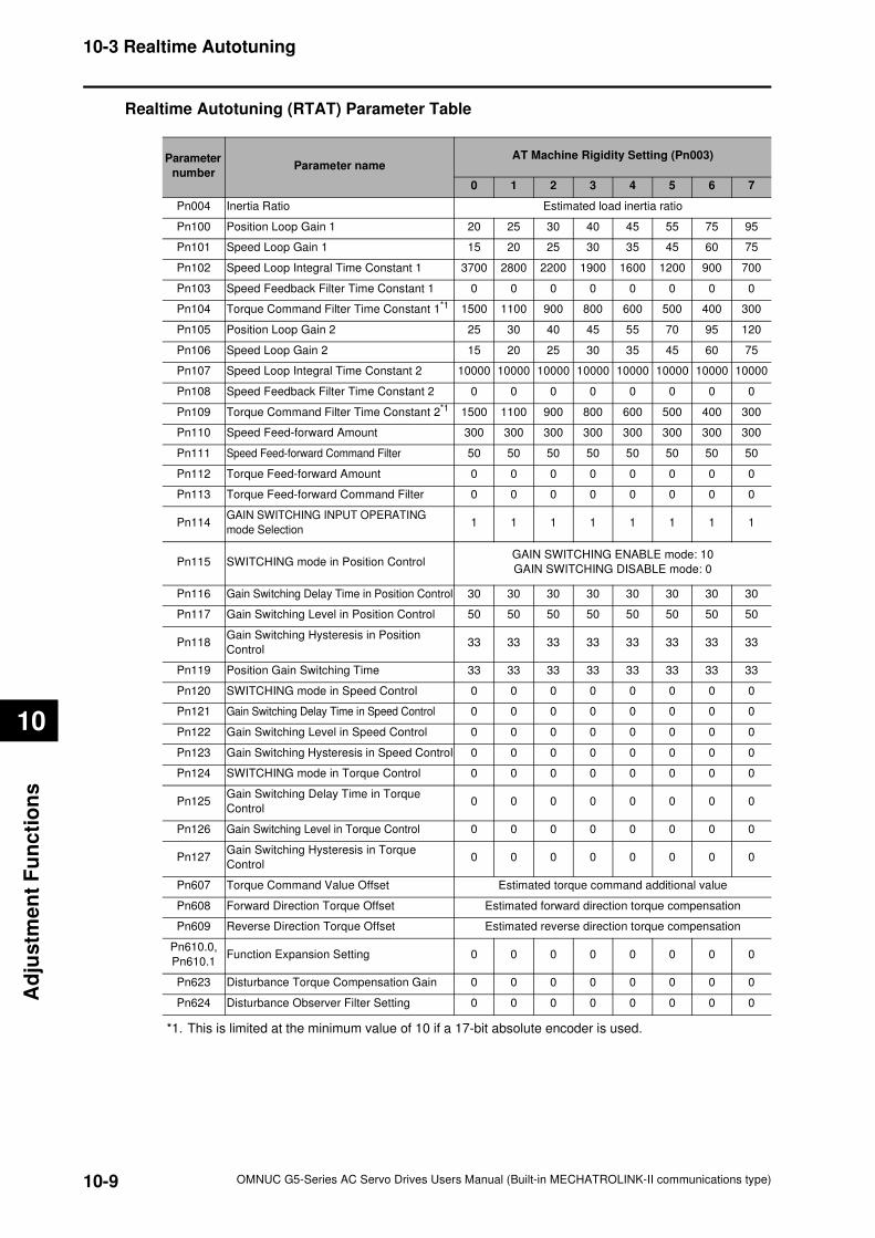
10-9
10-3 Realtime Autotuning
OMNUC G5-Series AC Servo Drives Users Manual (Built-in MECHATROLINK-II communications type)
10
Ad
justm
en
t F
un
cti
on
s
Realtime Autotuning (RTAT) Parameter Table
*1. This is limited at the minimum value of 10 if a 17-bit absolute encoder is used.
Parameter
numberParameter name
AT Machine Rigidity Setting (Pn003)
0 1 2 3 4 5 6 7
Pn004 Inertia Ratio Estimated load inertia ratio
Pn100 Position Loop Gain 1 20 25 30 40 45 55 75 95
Pn101 Speed Loop Gain 1 15 20 25 30 35 45 60 75
Pn102 Speed Loop Integral Time Constant 1 3700 2800 2200 1900 1600 1200 900 700
Pn103 Speed Feedback Filter Time Constant 1 0 0 0 0 0 0 0 0
Pn104 Torque Command Filter Time Constant 1*1 1500 1100 900 800 600 500 400 300
Pn105 Position Loop Gain 2 25 30 40 45 55 70 95 120
Pn106 Speed Loop Gain 2 15 20 25 30 35 45 60 75
Pn107 Speed Loop Integral Time Constant 2 10000 10000 10000 10000 10000 10000 10000 10000
Pn108 Speed Feedback Filter Time Constant 2 0 0 0 0 0 0 0 0
Pn109 Torque Command Filter Time Constant 2*1 1500 1100 900 800 600 500 400 300
Pn110 Speed Feed-forward Amount 300 300 300 300 300 300 300 300
Pn111 Speed Feed-forward Command Filter 50 50 50 50 50 50 50 50
Pn112 Torque Feed-forward Amount 0 0 0 0 0 0 0 0
Pn113 Torque Feed-forward Command Filter 0 0 0 0 0 0 0 0
Pn114GAIN SWITCHING INPUT OPERATING
mode Selection1 1 1 1 1 1 1 1
Pn115 SWITCHING mode in Position ControlGAIN SWITCHING ENABLE mode: 10
GAIN SWITCHING DISABLE mode: 0
Pn116 Gain Switching Delay Time in Position Control 30 30 30 30 30 30 30 30
Pn117 Gain Switching Level in Position Control 50 50 50 50 50 50 50 50
Pn118Gain Switching Hysteresis in Position
Control33 33 33 33 33 33 33 33
Pn119 Position Gain Switching Time 33 33 33 33 33 33 33 33
Pn120 SWITCHING mode in Speed Control 0 0 0 0 0 0 0 0
Pn121 Gain Switching Delay Time in Speed Control 0 0 0 0 0 0 0 0
Pn122 Gain Switching Level in Speed Control 0 0 0 0 0 0 0 0
Pn123 Gain Switching Hysteresis in Speed Control 0 0 0 0 0 0 0 0
Pn124 SWITCHING mode in Torque Control 0 0 0 0 0 0 0 0
Pn125Gain Switching Delay Time in Torque
Control0 0 0 0 0 0 0 0
Pn126 Gain Switching Level in Torque Control 0 0 0 0 0 0 0 0
Pn127Gain Switching Hysteresis in Torque
Control0 0 0 0 0 0 0 0
Pn607 Torque Command Value Offset Estimated torque command additional value
Pn608 Forward Direction Torque Offset Estimated forward direction torque compensation
Pn609 Reverse Direction Torque Offset Estimated reverse direction torque compensation
Pn610.0,
Pn610.1Function Expansion Setting 0 0 0 0 0 0 0 0
Pn623 Disturbance Torque Compensation Gain 0 0 0 0 0 0 0 0
Pn624 Disturbance Observer Filter Setting 0 0 0 0 0 0 0 0
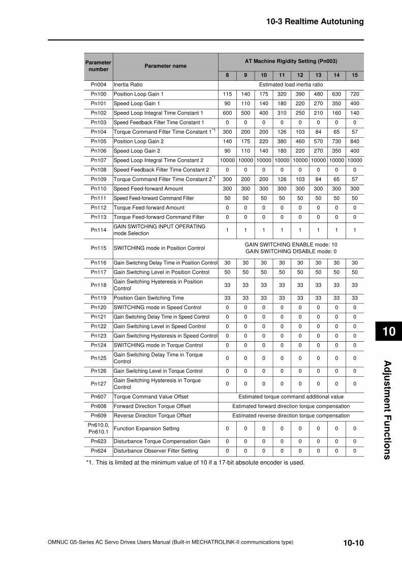
10-10
10-3 Realtime Autotuning
OMNUC G5-Series AC Servo Drives Users Manual (Built-in MECHATROLINK-II communications type)
10
Ad
jus
tme
nt F
un
ctio
ns
*1. This is limited at the minimum value of 10 if a 17-bit absolute encoder is used.
Parameter
numberParameter name
AT Machine Rigidity Setting (Pn003)
8 9 10 11 12 13 14 15
Pn004 Inertia Ratio Estimated load inertia ratio
Pn100 Position Loop Gain 1 115 140 175 320 390 480 630 720
Pn101 Speed Loop Gain 1 90 110 140 180 220 270 350 400
Pn102 Speed Loop Integral Time Constant 1 600 500 400 310 250 210 160 140
Pn103 Speed Feedback Filter Time Constant 1 0 0 0 0 0 0 0 0
Pn104 Torque Command Filter Time Constant 1*1 300 200 200 126 103 84 65 57
Pn105 Position Loop Gain 2 140 175 220 380 460 570 730 840
Pn106 Speed Loop Gain 2 90 110 140 180 220 270 350 400
Pn107 Speed Loop Integral Time Constant 2 10000 10000 10000 10000 10000 10000 10000 10000
Pn108 Speed Feedback Filter Time Constant 2 0 0 0 0 0 0 0 0
Pn109 Torque Command Filter Time Constant 2*1 300 200 200 126 103 84 65 57
Pn110 Speed Feed-forward Amount 300 300 300 300 300 300 300 300
Pn111 Speed Feed-forward Command Filter 50 50 50 50 50 50 50 50
Pn112 Torque Feed-forward Amount 0 0 0 0 0 0 0 0
Pn113 Torque Feed-forward Command Filter 0 0 0 0 0 0 0 0
Pn114GAIN SWITCHING INPUT OPERATING
mode Selection1 1 1 1 1 1 1 1
Pn115 SWITCHING mode in Position ControlGAIN SWITCHING ENABLE mode: 10
GAIN SWITCHING DISABLE mode: 0
Pn116 Gain Switching Delay Time in Position Control 30 30 30 30 30 30 30 30
Pn117 Gain Switching Level in Position Control 50 50 50 50 50 50 50 50
Pn118Gain Switching Hysteresis in Position
Control33 33 33 33 33 33 33 33
Pn119 Position Gain Switching Time 33 33 33 33 33 33 33 33
Pn120 SWITCHING mode in Speed Control 0 0 0 0 0 0 0 0
Pn121 Gain Switching Delay Time in Speed Control 0 0 0 0 0 0 0 0
Pn122 Gain Switching Level in Speed Control 0 0 0 0 0 0 0 0
Pn123 Gain Switching Hysteresis in Speed Control 0 0 0 0 0 0 0 0
Pn124 SWITCHING mode in Torque Control 0 0 0 0 0 0 0 0
Pn125Gain Switching Delay Time in Torque
Control0 0 0 0 0 0 0 0
Pn126 Gain Switching Level in Torque Control 0 0 0 0 0 0 0 0
Pn127Gain Switching Hysteresis in Torque
Control0 0 0 0 0 0 0 0
Pn607 Torque Command Value Offset Estimated torque command additional value
Pn608 Forward Direction Torque Offset Estimated forward direction torque compensation
Pn609 Reverse Direction Torque Offset Estimated reverse direction torque compensation
Pn610.0,
Pn610.1Function Expansion Setting 0 0 0 0 0 0 0 0
Pn623 Disturbance Torque Compensation Gain 0 0 0 0 0 0 0 0
Pn624 Disturbance Observer Filter Setting 0 0 0 0 0 0 0 0
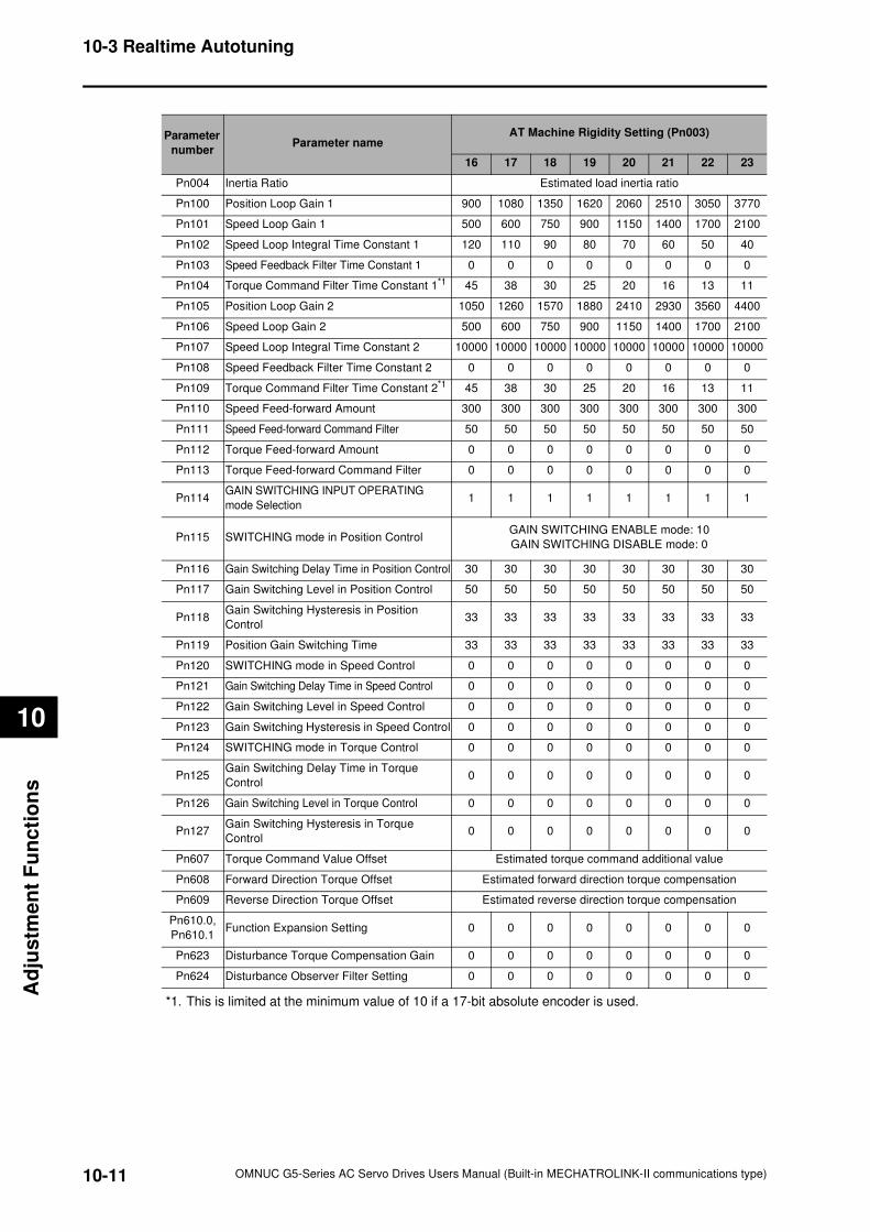
10-11
10-3 Realtime Autotuning
OMNUC G5-Series AC Servo Drives Users Manual (Built-in MECHATROLINK-II communications type)
10
Ad
justm
en
t F
un
cti
on
s
*1. This is limited at the minimum value of 10 if a 17-bit absolute encoder is used.
Parameter
numberParameter name
AT Machine Rigidity Setting (Pn003)
16 17 18 19 20 21 22 23
Pn004 Inertia Ratio Estimated load inertia ratio
Pn100 Position Loop Gain 1 900 1080 1350 1620 2060 2510 3050 3770
Pn101 Speed Loop Gain 1 500 600 750 900 1150 1400 1700 2100
Pn102 Speed Loop Integral Time Constant 1 120 110 90 80 70 60 50 40
Pn103 Speed Feedback Filter Time Constant 1 0 0 0 0 0 0 0 0
Pn104 Torque Command Filter Time Constant 1*1 45 38 30 25 20 16 13 11
Pn105 Position Loop Gain 2 1050 1260 1570 1880 2410 2930 3560 4400
Pn106 Speed Loop Gain 2 500 600 750 900 1150 1400 1700 2100
Pn107 Speed Loop Integral Time Constant 2 10000 10000 10000 10000 10000 10000 10000 10000
Pn108 Speed Feedback Filter Time Constant 2 0 0 0 0 0 0 0 0
Pn109 Torque Command Filter Time Constant 2*1 45 38 30 25 20 16 13 11
Pn110 Speed Feed-forward Amount 300 300 300 300 300 300 300 300
Pn111 Speed Feed-forward Command Filter 50 50 50 50 50 50 50 50
Pn112 Torque Feed-forward Amount 0 0 0 0 0 0 0 0
Pn113 Torque Feed-forward Command Filter 0 0 0 0 0 0 0 0
Pn114GAIN SWITCHING INPUT OPERATING
mode Selection1 1 1 1 1 1 1 1
Pn115 SWITCHING mode in Position ControlGAIN SWITCHING ENABLE mode: 10
GAIN SWITCHING DISABLE mode: 0
Pn116 Gain Switching Delay Time in Position Control 30 30 30 30 30 30 30 30
Pn117 Gain Switching Level in Position Control 50 50 50 50 50 50 50 50
Pn118Gain Switching Hysteresis in Position
Control33 33 33 33 33 33 33 33
Pn119 Position Gain Switching Time 33 33 33 33 33 33 33 33
Pn120 SWITCHING mode in Speed Control 0 0 0 0 0 0 0 0
Pn121 Gain Switching Delay Time in Speed Control 0 0 0 0 0 0 0 0
Pn122 Gain Switching Level in Speed Control 0 0 0 0 0 0 0 0
Pn123 Gain Switching Hysteresis in Speed Control 0 0 0 0 0 0 0 0
Pn124 SWITCHING mode in Torque Control 0 0 0 0 0 0 0 0
Pn125Gain Switching Delay Time in Torque
Control0 0 0 0 0 0 0 0
Pn126 Gain Switching Level in Torque Control 0 0 0 0 0 0 0 0
Pn127Gain Switching Hysteresis in Torque
Control0 0 0 0 0 0 0 0
Pn607 Torque Command Value Offset Estimated torque command additional value
Pn608 Forward Direction Torque Offset Estimated forward direction torque compensation
Pn609 Reverse Direction Torque Offset Estimated reverse direction torque compensation
Pn610.0,
Pn610.1Function Expansion Setting 0 0 0 0 0 0 0 0
Pn623 Disturbance Torque Compensation Gain 0 0 0 0 0 0 0 0
Pn624 Disturbance Observer Filter Setting 0 0 0 0 0 0 0 0
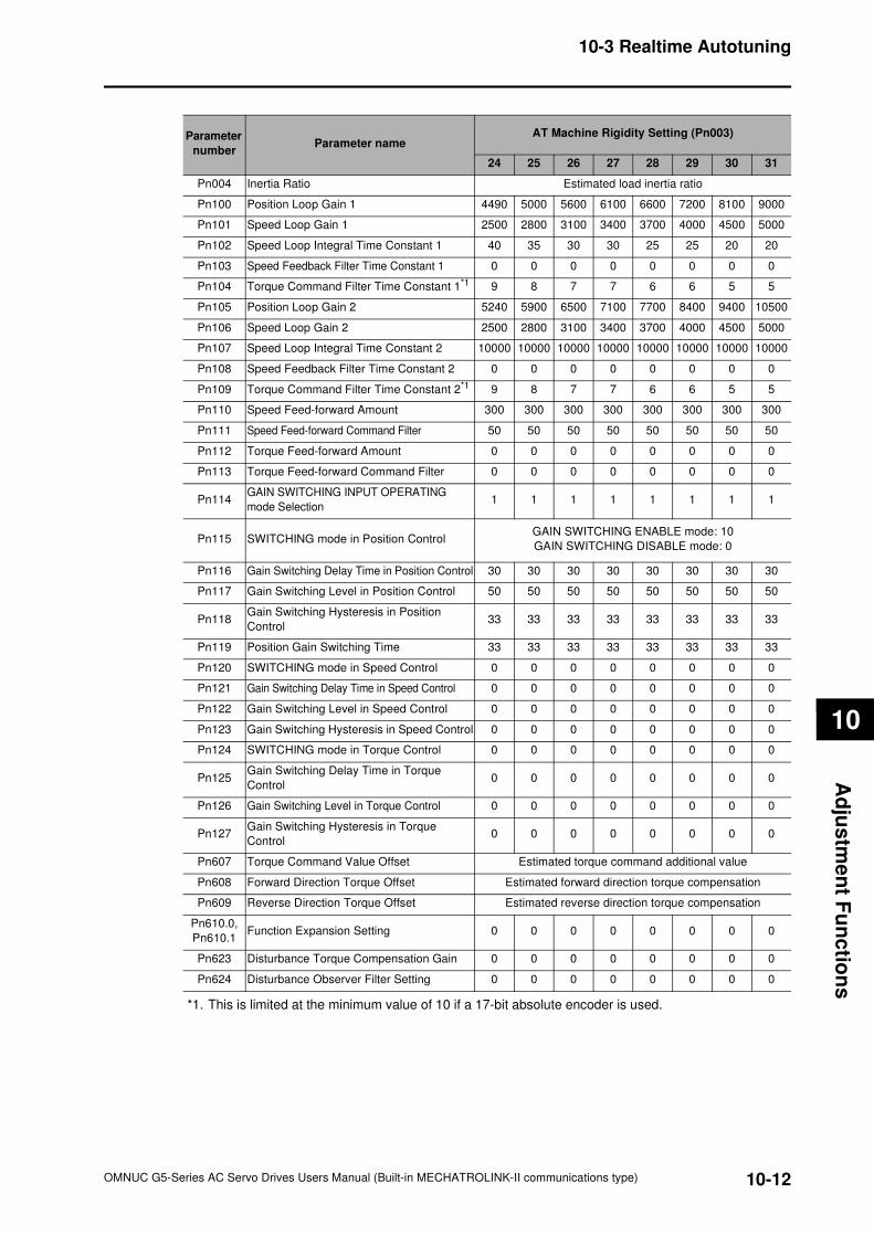
10-12
10-3 Realtime Autotuning
OMNUC G5-Series AC Servo Drives Users Manual (Built-in MECHATROLINK-II communications type)
10
Ad
jus
tme
nt F
un
ctio
ns
*1. This is limited at the minimum value of 10 if a 17-bit absolute encoder is used.
Parameter
numberParameter name
AT Machine Rigidity Setting (Pn003)
24 25 26 27 28 29 30 31
Pn004 Inertia Ratio Estimated load inertia ratio
Pn100 Position Loop Gain 1 4490 5000 5600 6100 6600 7200 8100 9000
Pn101 Speed Loop Gain 1 2500 2800 3100 3400 3700 4000 4500 5000
Pn102 Speed Loop Integral Time Constant 1 40 35 30 30 25 25 20 20
Pn103 Speed Feedback Filter Time Constant 1 0 0 0 0 0 0 0 0
Pn104 Torque Command Filter Time Constant 1*1 9 8 7 7 6 6 5 5
Pn105 Position Loop Gain 2 5240 5900 6500 7100 7700 8400 9400 10500
Pn106 Speed Loop Gain 2 2500 2800 3100 3400 3700 4000 4500 5000
Pn107 Speed Loop Integral Time Constant 2 10000 10000 10000 10000 10000 10000 10000 10000
Pn108 Speed Feedback Filter Time Constant 2 0 0 0 0 0 0 0 0
Pn109 Torque Command Filter Time Constant 2*1 9 8 7 7 6 6 5 5
Pn110 Speed Feed-forward Amount 300 300 300 300 300 300 300 300
Pn111 Speed Feed-forward Command Filter 50 50 50 50 50 50 50 50
Pn112 Torque Feed-forward Amount 0 0 0 0 0 0 0 0
Pn113 Torque Feed-forward Command Filter 0 0 0 0 0 0 0 0
Pn114GAIN SWITCHING INPUT OPERATING
mode Selection1 1 1 1 1 1 1 1
Pn115 SWITCHING mode in Position ControlGAIN SWITCHING ENABLE mode: 10
GAIN SWITCHING DISABLE mode: 0
Pn116 Gain Switching Delay Time in Position Control 30 30 30 30 30 30 30 30
Pn117 Gain Switching Level in Position Control 50 50 50 50 50 50 50 50
Pn118Gain Switching Hysteresis in Position
Control33 33 33 33 33 33 33 33
Pn119 Position Gain Switching Time 33 33 33 33 33 33 33 33
Pn120 SWITCHING mode in Speed Control 0 0 0 0 0 0 0 0
Pn121 Gain Switching Delay Time in Speed Control 0 0 0 0 0 0 0 0
Pn122 Gain Switching Level in Speed Control 0 0 0 0 0 0 0 0
Pn123 Gain Switching Hysteresis in Speed Control 0 0 0 0 0 0 0 0
Pn124 SWITCHING mode in Torque Control 0 0 0 0 0 0 0 0
Pn125Gain Switching Delay Time in Torque
Control0 0 0 0 0 0 0 0
Pn126 Gain Switching Level in Torque Control 0 0 0 0 0 0 0 0
Pn127Gain Switching Hysteresis in Torque
Control0 0 0 0 0 0 0 0
Pn607 Torque Command Value Offset Estimated torque command additional value
Pn608 Forward Direction Torque Offset Estimated forward direction torque compensation
Pn609 Reverse Direction Torque Offset Estimated reverse direction torque compensation
Pn610.0,
Pn610.1Function Expansion Setting 0 0 0 0 0 0 0 0
Pn623 Disturbance Torque Compensation Gain 0 0 0 0 0 0 0 0
Pn624 Disturbance Observer Filter Setting 0 0 0 0 0 0 0 0
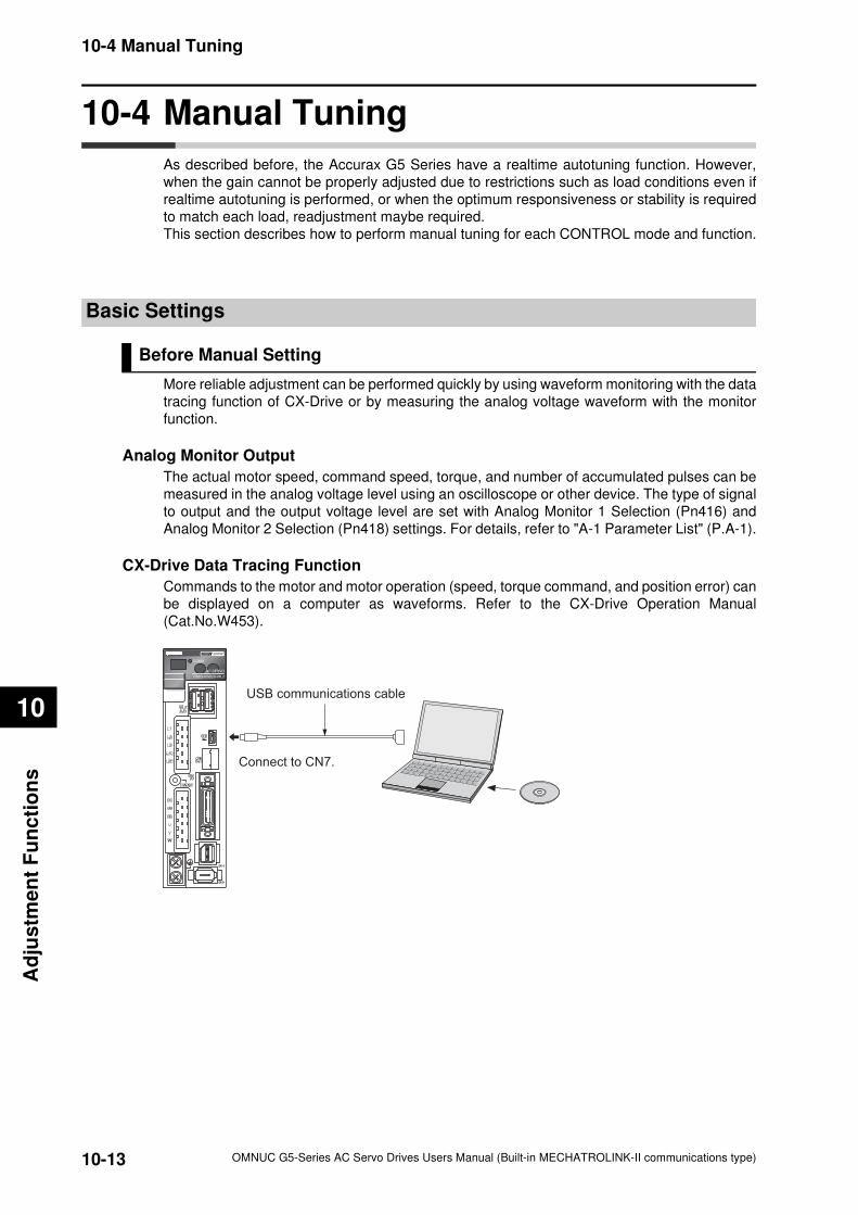
10-13
10-4 Manual Tuning
OMNUC G5-Series AC Servo Drives Users Manual (Built-in MECHATROLINK-II communications type)
10
Ad
justm
en
t F
un
cti
on
s
10-4 Manual Tuning
As described before, the Accurax G5 Series have a realtime autotuning function. However,
when the gain cannot be properly adjusted due to restrictions such as load conditions even if
realtime autotuning is performed, or when the optimum responsiveness or stability is required
to match each load, readjustment maybe required.
This section describes how to perform manual tuning for each CONTROL mode and function.
Basic Settings
Before Manual Setting
More reliable adjustment can be performed quickly by using waveform monitoring with the data
tracing function of CX-Drive or by measuring the analog voltage waveform with the monitor
function.
Analog Monitor Output
The actual motor speed, command speed, torque, and number of accumulated pulses can be
measured in the analog voltage level using an oscilloscope or other device. The type of signal
to output and the output voltage level are set with Analog Monitor 1 Selection (Pn416) and
Analog Monitor 2 Selection (Pn418) settings. For details, refer to "A-1 Parameter List" (P.A-1).
CX-Drive Data Tracing Function
Commands to the motor and motor operation (speed, torque command, and position error) can
be displayed on a computer as waveforms. Refer to the CX-Drive Operation Manual
(Cat.No.W453).
USB communications cable
Connect to CN7.
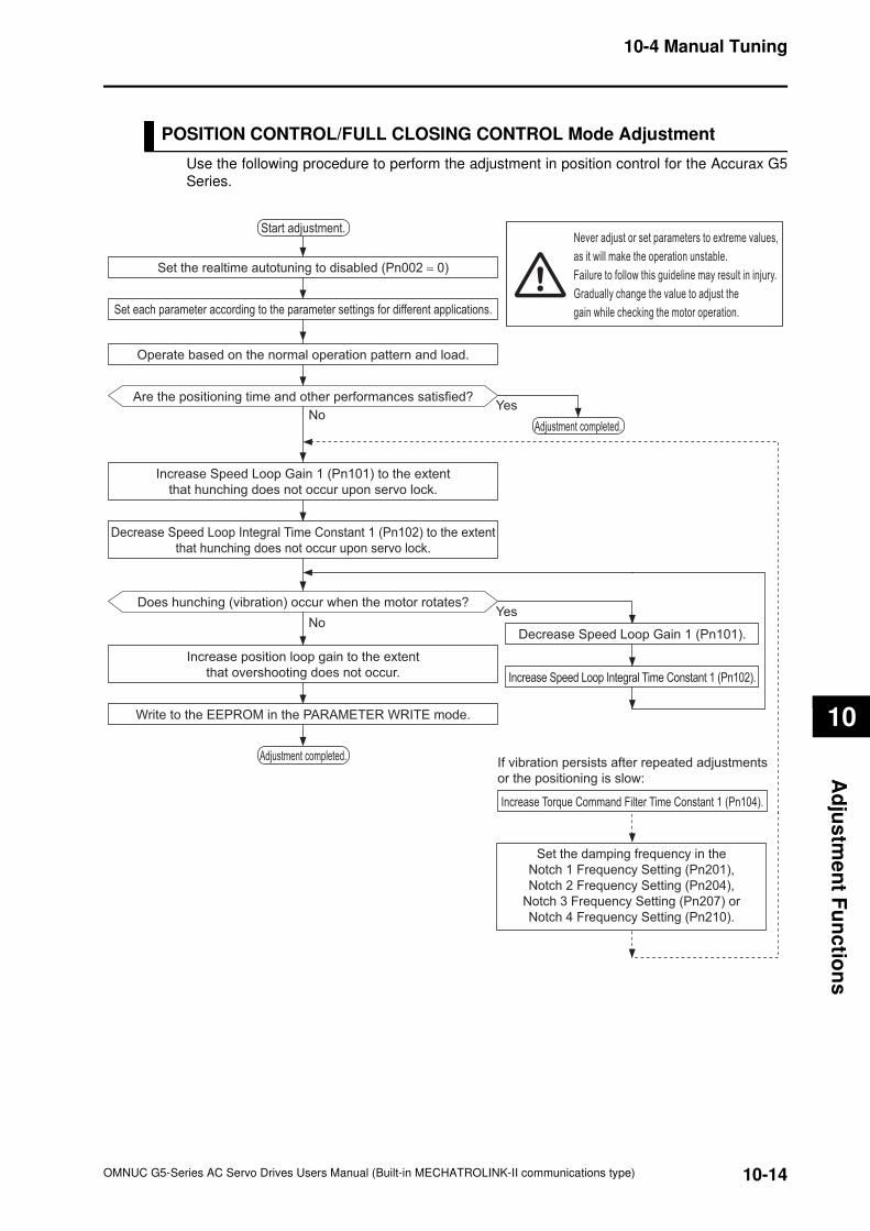
10-14
10-4 Manual Tuning
OMNUC G5-Series AC Servo Drives Users Manual (Built-in MECHATROLINK-II communications type)
10
Ad
jus
tme
nt F
un
ctio
ns
POSITION CONTROL/FULL CLOSING CONTROL Mode Adjustment
Use the following procedure to perform the adjustment in position control for the Accurax G5
Series.
Write to the EEPROM in the PARAMETER WRITE mode.
Start adjustment.
YesNo
Adjustment completed.
Set the realtime autotuning to disabled (Pn002 = 0)
Set each parameter according to the parameter settings for different applications.
Operate based on the normal operation pattern and load.
Are the positioning time and other performances satisfied?
Adjustment completed.
Increase Speed Loop Gain 1 (Pn101) to the extent
that hunching does not occur upon servo lock.
Decrease Speed Loop Integral Time Constant 1 (Pn102) to the extent
that hunching does not occur upon servo lock.
Does hunching (vibration) occur when the motor rotates?
NoDecrease Speed Loop Gain 1 (Pn101).
Increase Speed Loop Integral Time Constant 1 (Pn102).
Increase position loop gain to the extent
that overshooting does not occur.
Yes
If vibration persists after repeated adjustments
or the positioning is slow:
Increase Torque Command Filter Time Constant 1 (Pn104).
Never adjust or set parameters to extreme values,
as it will make the operation unstable.
Failure to follow this guideline may result in injury.
Gradually change the value to adjust the
gain while checking the motor operation.
Set the damping frequency in the
Notch 1 Frequency Setting (Pn201),
Notch 2 Frequency Setting (Pn204),
Notch 3 Frequency Setting (Pn207) or
Notch 4 Frequency Setting (Pn210).
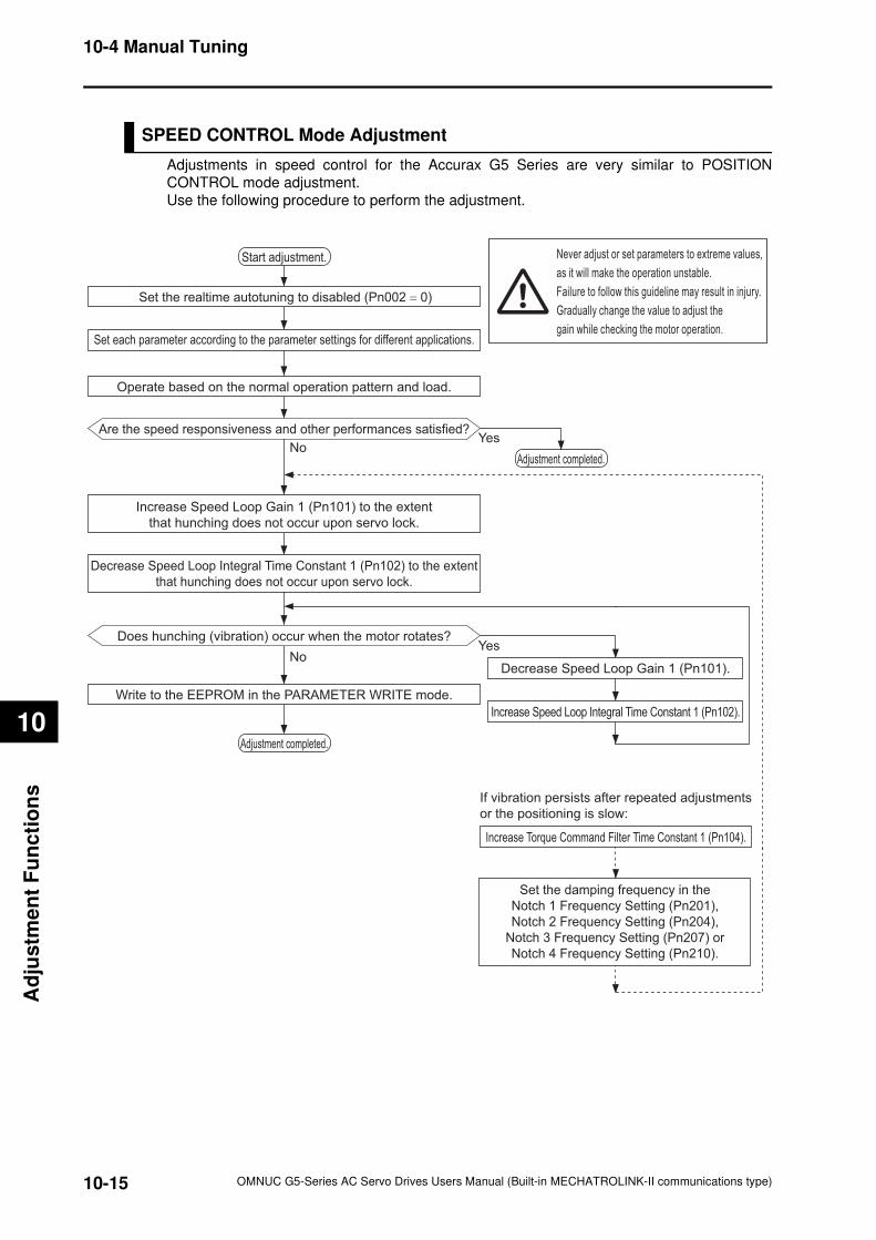
10-15
10-4 Manual Tuning
OMNUC G5-Series AC Servo Drives Users Manual (Built-in MECHATROLINK-II communications type)
10
Ad
justm
en
t F
un
cti
on
s
SPEED CONTROL Mode Adjustment
Adjustments in speed control for the Accurax G5 Series are very similar to POSITION
CONTROL mode adjustment.
Use the following procedure to perform the adjustment.
Write to the EEPROM in the PARAMETER WRITE mode.
Start adjustment.
YesNo
Adjustment completed.
Set the realtime autotuning to disabled (Pn002 = 0)
Set each parameter according to the parameter settings for different applications.
Operate based on the normal operation pattern and load.
Are the speed responsiveness and other performances satisfied?
Adjustment completed.
Increase Speed Loop Gain 1 (Pn101) to the extent
that hunching does not occur upon servo lock.
Decrease Speed Loop Integral Time Constant 1 (Pn102) to the extent
that hunching does not occur upon servo lock.
Does hunching (vibration) occur when the motor rotates?
NoDecrease Speed Loop Gain 1 (Pn101).
Increase Speed Loop Integral Time Constant 1 (Pn102).
Yes
If vibration persists after repeated adjustments
or the positioning is slow:
Increase Torque Command Filter Time Constant 1 (Pn104).
Never adjust or set parameters to extreme values,
as it will make the operation unstable.
Failure to follow this guideline may result in injury.
Gradually change the value to adjust the
gain while checking the motor operation.
Set the damping frequency in the
Notch 1 Frequency Setting (Pn201),
Notch 2 Frequency Setting (Pn204),
Notch 3 Frequency Setting (Pn207) or
Notch 4 Frequency Setting (Pn210).
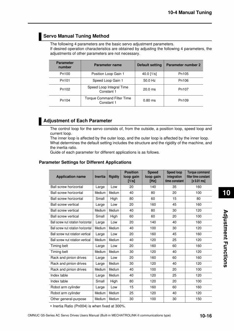
10-16
10-4 Manual Tuning
OMNUC G5-Series AC Servo Drives Users Manual (Built-in MECHATROLINK-II communications type)
10
Ad
jus
tme
nt F
un
ctio
ns
Servo Manual Tuning Method
The following 4 parameters are the basic servo adjustment parameters.
If desired operation characteristics are obtained by adjusting the following 4 parameters, the
adjustments of other parameters are not necessary.
Adjustment of Each Parameter
The control loop for the servo consists of, from the outside, a position loop, speed loop and
current loop.
The inner loop is affected by the outer loop, and the outer loop is affected by the inner loop.
What determines the default setting includes the structure and the rigidity of the machine, and
the inertia ratio.
Guide of each parameter for different applications is as follows.
Parameter Settings for Different Applications
Inertia Ratio (Pn004) is when fixed at 300%.
Parameter
numberParameter name Default setting Parameter number 2
Pn100 Position Loop Gain 1 40.0 [1/s] Pn105
Pn101 Speed Loop Gain 1 50.0 Hz Pn106
Pn102Speed Loop Integral Time
Constant 120.0 ms Pn107
Pn104Torque Command Filter Time
Constant 10.80 ms Pn109
Application name Inertia Rigidity
Position
loop gain
[1/s]
Speed
loop gain
[Hz]
Speed loop
integration
time constant
Torque command
filter time constant
[x 0.01 ms]
Ball screw horizontal Large Low 20 140 35 160
Ball screw horizontal Medium Medium 40 80 20 100
Ball screw horizontal Small High 80 60 15 80
Ball screw vertical Large Low 20 160 45 160
Ball screw vertical Medium Medium 40 80 30 120
Ball screw vertical Small High 60 60 20 100
Ball screw nut rotation horizontal Large Low 20 140 40 160
Ball screw nut rotation horizontal Medium Medium 40 100 30 120
Ball screw nut rotation vertical Large Low 20 160 45 160
Ball screw nut rotation vertical Medium Medium 40 120 25 120
Timing belt Large Low 20 160 60 160
Timing belt Medium Medium 30 120 40 120
Rack and pinion drives Large Low 20 160 60 160
Rack and pinion drives Large Medium 30 120 40 120
Rack and pinion drives Medium Medium 40 100 20 100
Index table Large Medium 40 120 25 120
Index table Small High 80 120 20 100
Robot arm cylinder Large Low 15 160 60 160
Robot arm cylinder Medium Medium 25 120 40 120
Other general-purpose Medium Medium 30 100 30 150
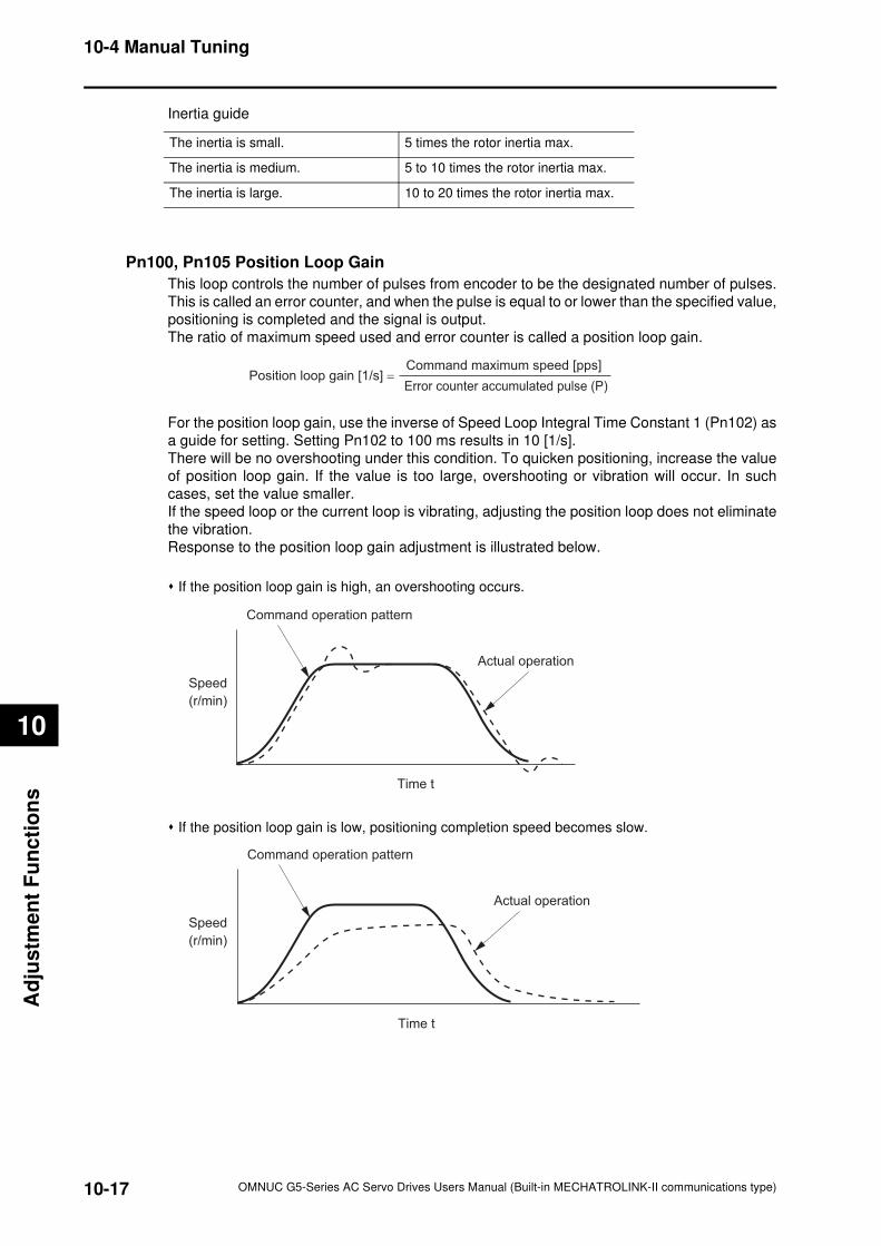
10-17
10-4 Manual Tuning
OMNUC G5-Series AC Servo Drives Users Manual (Built-in MECHATROLINK-II communications type)
10
Ad
justm
en
t F
un
cti
on
s
Inertia guide
Pn100, Pn105 Position Loop Gain
This loop controls the number of pulses from encoder to be the designated number of pulses.
This is called an error counter, and when the pulse is equal to or lower than the specified value,
positioning is completed and the signal is output.
The ratio of maximum speed used and error counter is called a position loop gain.
For the position loop gain, use the inverse of Speed Loop Integral Time Constant 1 (Pn102) as
a guide for setting. Setting Pn102 to 100 ms results in 10 [1/s].
There will be no overshooting under this condition. To quicken positioning, increase the value
of position loop gain. If the value is too large, overshooting or vibration will occur. In such
cases, set the value smaller.
If the speed loop or the current loop is vibrating, adjusting the position loop does not eliminate
the vibration.
Response to the position loop gain adjustment is illustrated below.
If the position loop gain is high, an overshooting occurs.
If the position loop gain is low, positioning completion speed becomes slow.
The inertia is small. 5 times the rotor inertia max.
The inertia is medium. 5 to 10 times the rotor inertia max.
The inertia is large. 10 to 20 times the rotor inertia max.
Command maximum speed [pps]
Error counter accumulated pulse (P)Position loop gain [1/s] =
Actual operation
Command operation pattern
Speed
(r/min)
Time t
Actual operation
Command operation pattern
Speed
(r/min)
Time t
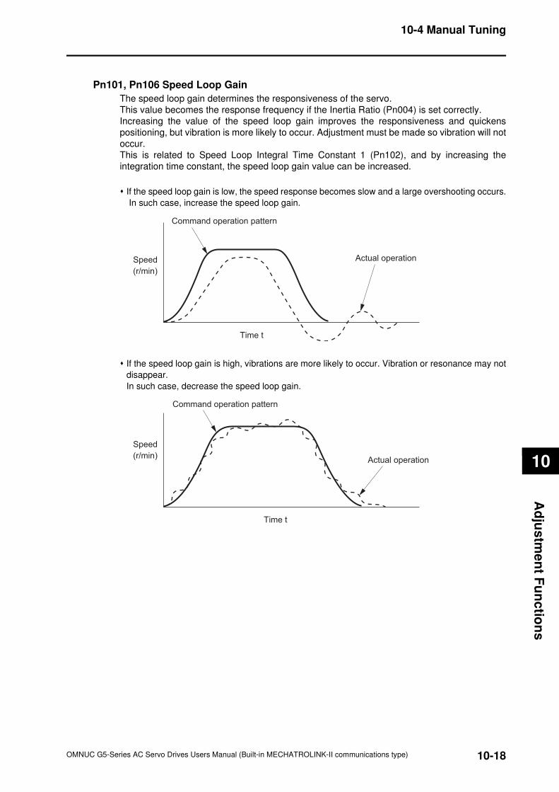
10-18
10-4 Manual Tuning
OMNUC G5-Series AC Servo Drives Users Manual (Built-in MECHATROLINK-II communications type)
10
Ad
jus
tme
nt F
un
ctio
ns
Pn101, Pn106 Speed Loop Gain
The speed loop gain determines the responsiveness of the servo.
This value becomes the response frequency if the Inertia Ratio (Pn004) is set correctly.
Increasing the value of the speed loop gain improves the responsiveness and quickens
positioning, but vibration is more likely to occur. Adjustment must be made so vibration will not
occur.
This is related to Speed Loop Integral Time Constant 1 (Pn102), and by increasing the
integration time constant, the speed loop gain value can be increased.
If the speed loop gain is low, the speed response becomes slow and a large overshooting occurs.
In such case, increase the speed loop gain.
If the speed loop gain is high, vibrations are more likely to occur. Vibration or resonance may not
disappear.
In such case, decrease the speed loop gain.
Actual operation
Command operation pattern
Speed
(r/min)
Time t
Actual operation
Command operation pattern
Speed
(r/min)
Time t
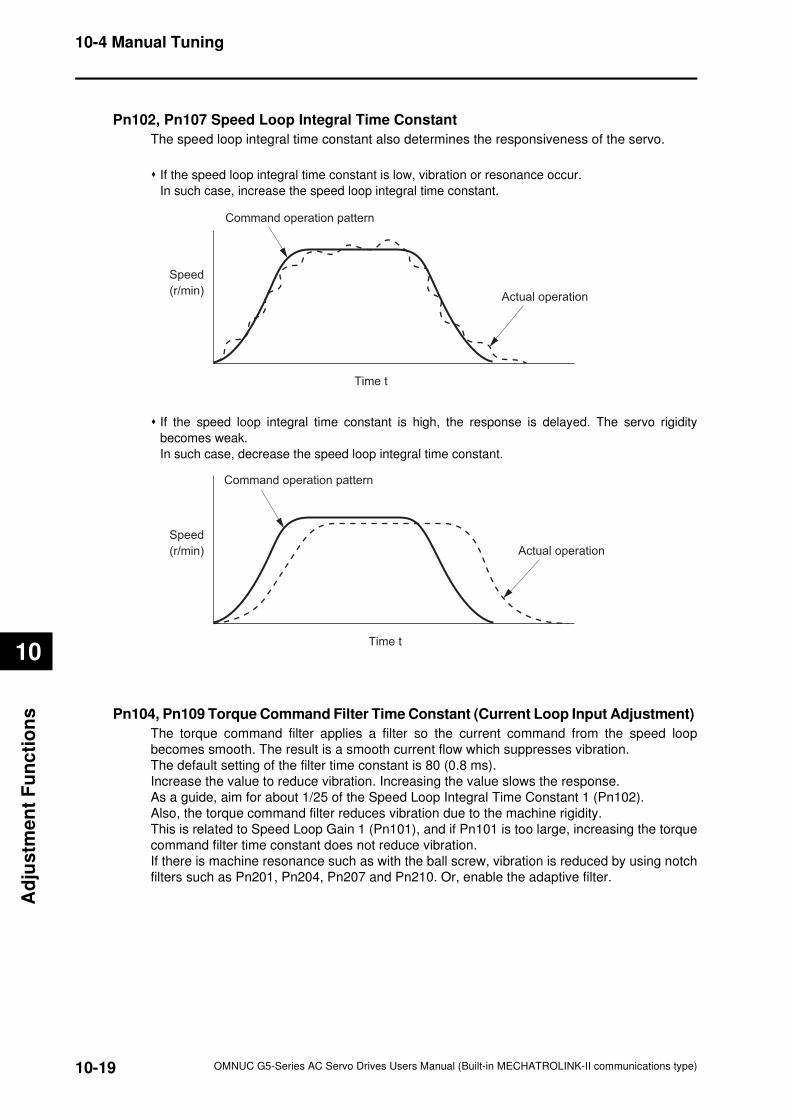
10-19
10-4 Manual Tuning
OMNUC G5-Series AC Servo Drives Users Manual (Built-in MECHATROLINK-II communications type)
10
Ad
justm
en
t F
un
cti
on
s
Pn102, Pn107 Speed Loop Integral Time Constant
The speed loop integral time constant also determines the responsiveness of the servo.
If the speed loop integral time constant is low, vibration or resonance occur.
In such case, increase the speed loop integral time constant.
If the speed loop integral time constant is high, the response is delayed. The servo rigidity
becomes weak.
In such case, decrease the speed loop integral time constant.
Pn104, Pn109 Torque Command Filter Time Constant (Current Loop Input Adjustment)
The torque command filter applies a filter so the current command from the speed loop
becomes smooth. The result is a smooth current flow which suppresses vibration.
The default setting of the filter time constant is 80 (0.8 ms).
Increase the value to reduce vibration. Increasing the value slows the response.
As a guide, aim for about 1/25 of the Speed Loop Integral Time Constant 1 (Pn102).
Also, the torque command filter reduces vibration due to the machine rigidity.
This is related to Speed Loop Gain 1 (Pn101), and if Pn101 is too large, increasing the torque
command filter time constant does not reduce vibration.
If there is machine resonance such as with the ball screw, vibration is reduced by using notch
filters such as Pn201, Pn204, Pn207 and Pn210. Or, enable the adaptive filter.
Actual operation
Command operation pattern
Speed
(r/min)
Time t
Actual operation
Command operation pattern
Speed
(r/min)
Time t
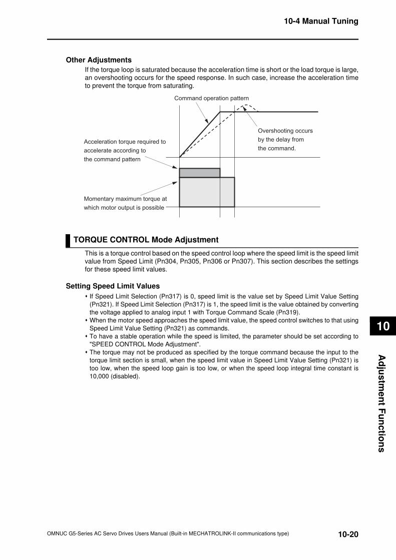
10-20
10-4 Manual Tuning
OMNUC G5-Series AC Servo Drives Users Manual (Built-in MECHATROLINK-II communications type)
10
Ad
jus
tme
nt F
un
ctio
ns
Other Adjustments
If the torque loop is saturated because the acceleration time is short or the load torque is large,
an overshooting occurs for the speed response. In such case, increase the acceleration time
to prevent the torque from saturating.
TORQUE CONTROL Mode Adjustment
This is a torque control based on the speed control loop where the speed limit is the speed limit
value from Speed Limit (Pn304, Pn305, Pn306 or Pn307). This section describes the settings
for these speed limit values.
Setting Speed Limit Values
If Speed Limit Selection (Pn317) is 0, speed limit is the value set by Speed Limit Value Setting
(Pn321). If Speed Limit Selection (Pn317) is 1, the speed limit is the value obtained by converting
the voltage applied to analog input 1 with Torque Command Scale (Pn319).
When the motor speed approaches the speed limit value, the speed control switches to that using
Speed Limit Value Setting (Pn321) as commands.
To have a stable operation while the speed is limited, the parameter should be set according to
"SPEED CONTROL Mode Adjustment".
The torque may not be produced as specified by the torque command because the input to the
torque limit section is small, when the speed limit value in Speed Limit Value Setting (Pn321) is
too low, when the speed loop gain is too low, or when the speed loop integral time constant is
10,000 (disabled).
Command operation pattern
Momentary maximum torque at
which motor output is possible
Acceleration torque required to
accelerate according to
the command pattern
Overshooting occurs
by the delay from
the command.
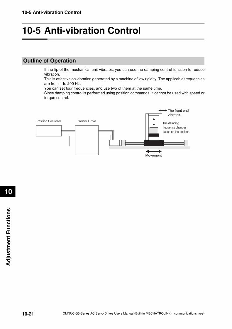
10-21
10-5 Anti-vibration Control
OMNUC G5-Series AC Servo Drives Users Manual (Built-in MECHATROLINK-II communications type)
10
Ad
justm
en
t F
un
cti
on
s
10-5 Anti-vibration Control
Outline of Operation
If the tip of the mechanical unit vibrates, you can use the damping control function to reduce
vibration.
This is effective on vibration generated by a machine of low rigidity. The applicable frequencies
are from 1 to 200 Hz.
You can set four frequencies, and use two of them at the same time.
Since damping control is performed using position commands, it cannot be used with speed or
torque control.
Position Controller Servo Drive
The front end
vibrates.
The damping
frequency changes
based on the position.
Movement
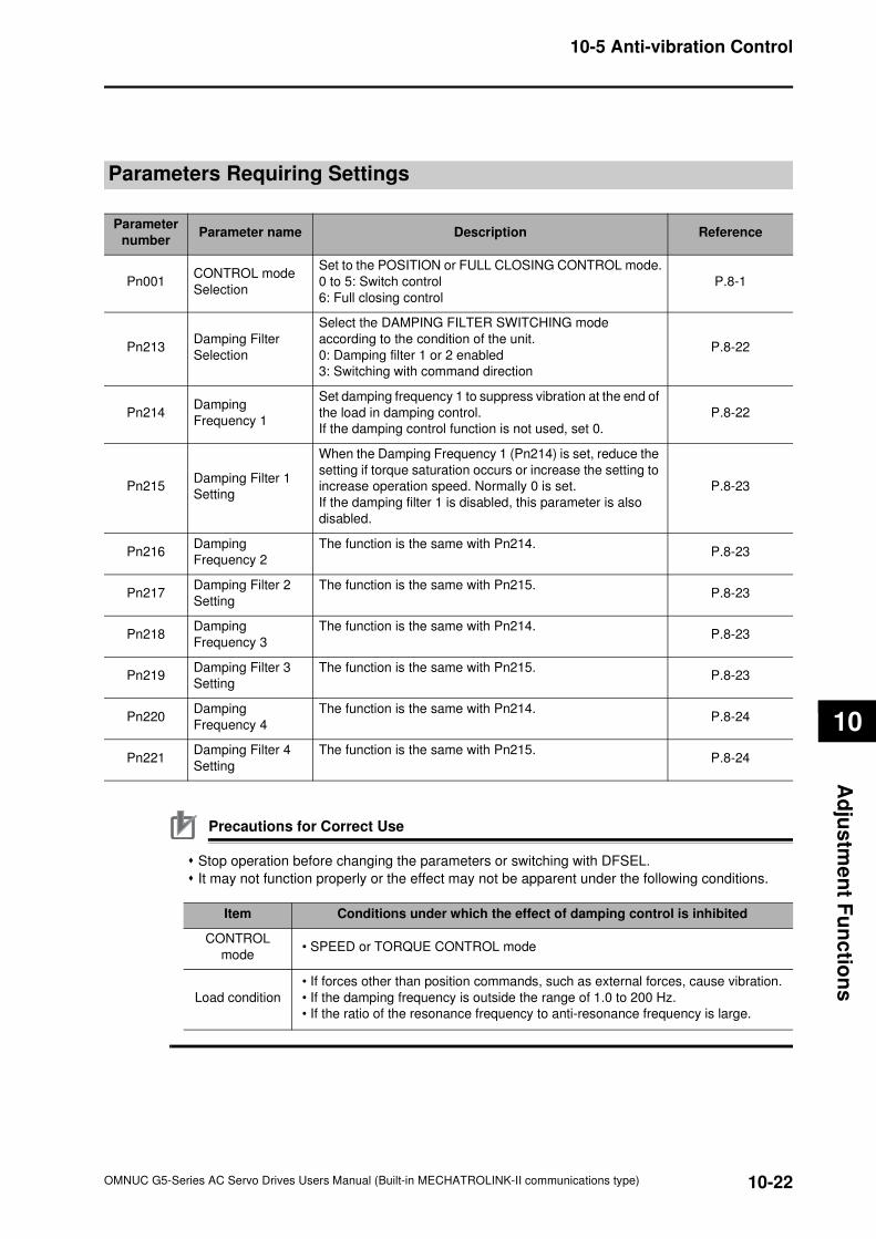
10-22
10-5 Anti-vibration Control
OMNUC G5-Series AC Servo Drives Users Manual (Built-in MECHATROLINK-II communications type)
10
Ad
jus
tme
nt F
un
ctio
ns
Parameters Requiring Settings
Precautions for Correct Use
Stop operation before changing the parameters or switching with DFSEL.
It may not function properly or the effect may not be apparent under the following conditions.
Parameter
numberParameter name Description Reference
Pn001CONTROL mode
Selection
Set to the POSITION or FULL CLOSING CONTROL mode.
0 to 5: Switch control
6: Full closing control
P.8-1
Pn213Damping Filter
Selection
Select the DAMPING FILTER SWITCHING mode
according to the condition of the unit.
0: Damping filter 1 or 2 enabled
3: Switching with command direction
P.8-22
Pn214Damping
Frequency 1
Set damping frequency 1 to suppress vibration at the end of
the load in damping control.
If the damping control function is not used, set 0.
P.8-22
Pn215Damping Filter 1
Setting
When the Damping Frequency 1 (Pn214) is set, reduce the
setting if torque saturation occurs or increase the setting to
increase operation speed. Normally 0 is set.
If the damping filter 1 is disabled, this parameter is also
disabled.
P.8-23
Pn216Damping
Frequency 2
The function is the same with Pn214.P.8-23
Pn217Damping Filter 2
Setting
The function is the same with Pn215.P.8-23
Pn218Damping
Frequency 3
The function is the same with Pn214.P.8-23
Pn219Damping Filter 3
Setting
The function is the same with Pn215.P.8-23
Pn220Damping
Frequency 4
The function is the same with Pn214.P.8-24
Pn221Damping Filter 4
Setting
The function is the same with Pn215.P.8-24
Item Conditions under which the effect of damping control is inhibited
CONTROL
mode• SPEED or TORQUE CONTROL mode
Load condition
• If forces other than position commands, such as external forces, cause vibration.
• If the damping frequency is outside the range of 1.0 to 200 Hz.
• If the ratio of the resonance frequency to anti-resonance frequency is large.
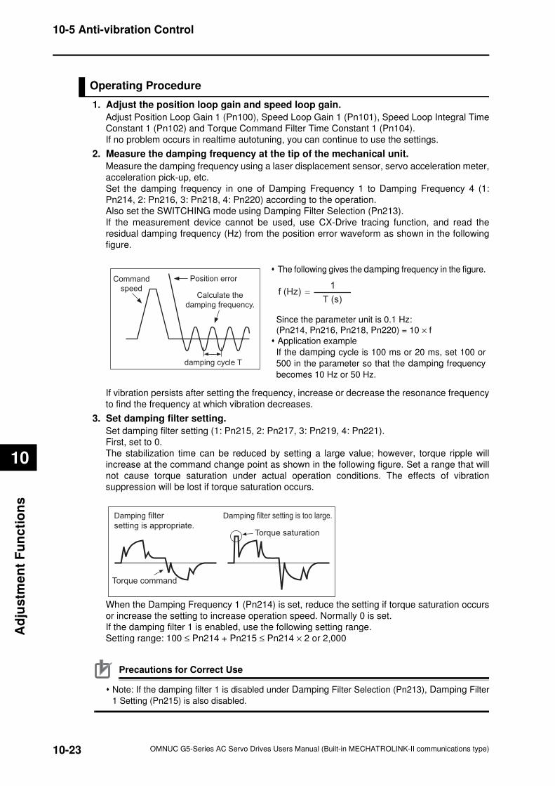
10-23
10-5 Anti-vibration Control
OMNUC G5-Series AC Servo Drives Users Manual (Built-in MECHATROLINK-II communications type)
10
Ad
justm
en
t F
un
cti
on
s
Operating Procedure
1. Adjust the position loop gain and speed loop gain.
Adjust Position Loop Gain 1 (Pn100), Speed Loop Gain 1 (Pn101), Speed Loop Integral Time
Constant 1 (Pn102) and Torque Command Filter Time Constant 1 (Pn104).
If no problem occurs in realtime autotuning, you can continue to use the settings.
2. Measure the damping frequency at the tip of the mechanical unit.
Measure the damping frequency using a laser displacement sensor, servo acceleration meter,
acceleration pick-up, etc.
Set the damping frequency in one of Damping Frequency 1 to Damping Frequency 4 (1:
Pn214, 2: Pn216, 3: Pn218, 4: Pn220) according to the operation.
Also set the SWITCHING mode using Damping Filter Selection (Pn213).
If the measurement device cannot be used, use CX-Drive tracing function, and read the
residual damping frequency (Hz) from the position error waveform as shown in the following
figure.
If vibration persists after setting the frequency, increase or decrease the resonance frequency
to find the frequency at which vibration decreases.
3. Set damping filter setting.
Set damping filter setting (1: Pn215, 2: Pn217, 3: Pn219, 4: Pn221).
First, set to 0.
The stabilization time can be reduced by setting a large value; however, torque ripple will
increase at the command change point as shown in the following figure. Set a range that will
not cause torque saturation under actual operation conditions. The effects of vibration
suppression will be lost if torque saturation occurs.
When the Damping Frequency 1 (Pn214) is set, reduce the setting if torque saturation occurs
or increase the setting to increase operation speed. Normally 0 is set.
If the damping filter 1 is enabled, use the following setting range.
Setting range: 100 ≤ Pn214 + Pn215 ≤ Pn214 × 2 or 2,000
Precautions for Correct Use
Note: If the damping filter 1 is disabled under Damping Filter Selection (Pn213), Damping Filter
1 Setting (Pn215) is also disabled.
The following gives the damping frequency in the figure.
Since the parameter unit is 0.1 Hz:
(Pn214, Pn216, Pn218, Pn220) = 10 × f
Application example
If the damping cycle is 100 ms or 20 ms, set 100 or
500 in the parameter so that the damping frequency
becomes 10 Hz or 50 Hz.
Command
speed
Position error
Calculate the
damping frequency.
damping cycle T
1
T (s)f (Hz) =
Torque command
Torque saturation
Damping filter setting is too large.Damping filter
setting is appropriate.
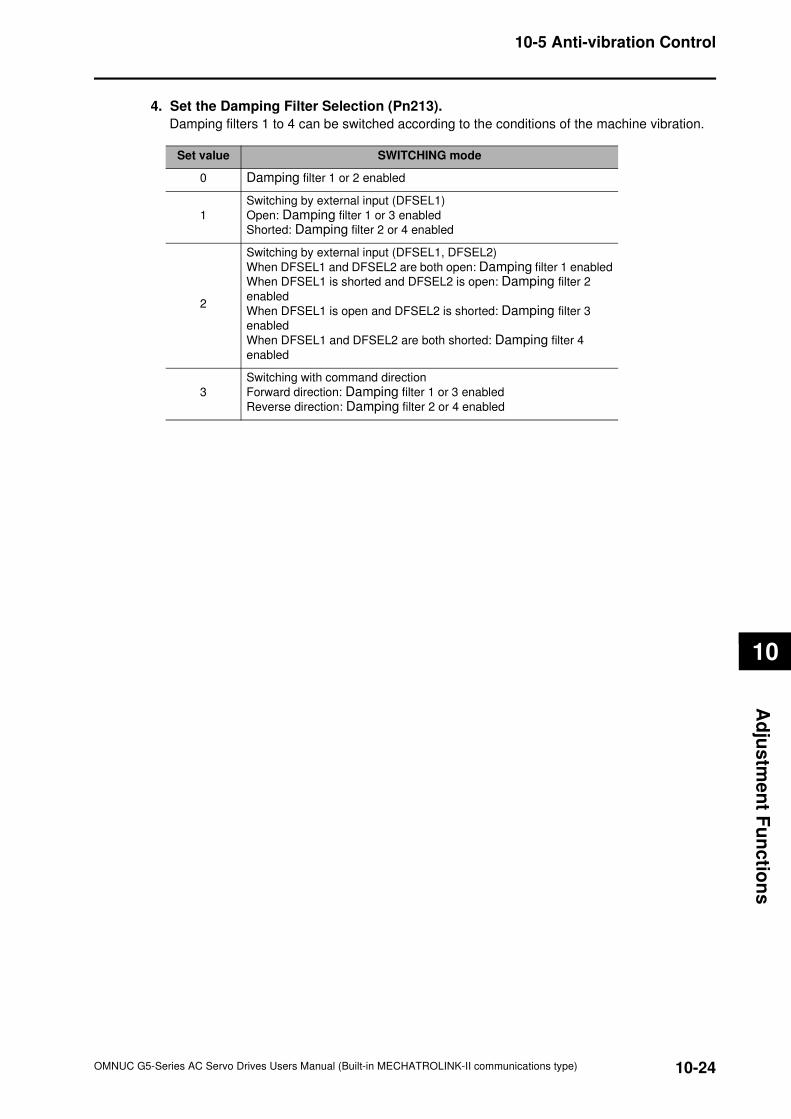
10-24
10-5 Anti-vibration Control
OMNUC G5-Series AC Servo Drives Users Manual (Built-in MECHATROLINK-II communications type)
10
Ad
jus
tme
nt F
un
ctio
ns
4. Set the Damping Filter Selection (Pn213).
Damping filters 1 to 4 can be switched according to the conditions of the machine vibration.
Set value SWITCHING mode
0 Damping filter 1 or 2 enabled
1
Switching by external input (DFSEL1)
Open: Damping filter 1 or 3 enabled
Shorted: Damping filter 2 or 4 enabled
2
Switching by external input (DFSEL1, DFSEL2)
When DFSEL1 and DFSEL2 are both open: Damping filter 1 enabled
When DFSEL1 is shorted and DFSEL2 is open: Damping filter 2
enabled
When DFSEL1 is open and DFSEL2 is shorted: Damping filter 3
enabled
When DFSEL1 and DFSEL2 are both shorted: Damping filter 4
enabled
3
Switching with command direction
Forward direction: Damping filter 1 or 3 enabled
Reverse direction: Damping filter 2 or 4 enabled
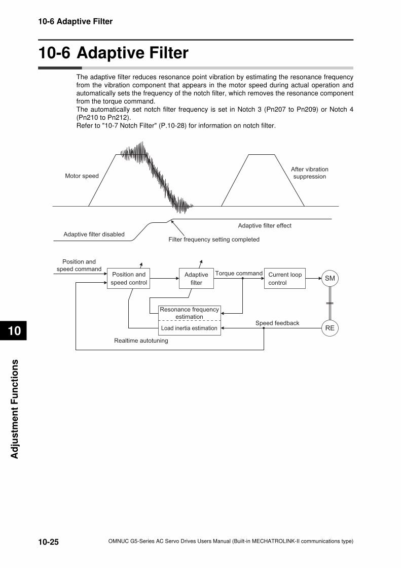
10-25
10-6 Adaptive Filter
OMNUC G5-Series AC Servo Drives Users Manual (Built-in MECHATROLINK-II communications type)
10
Ad
justm
en
t F
un
cti
on
s
10-6 Adaptive Filter
The adaptive filter reduces resonance point vibration by estimating the resonance frequency
from the vibration component that appears in the motor speed during actual operation and
automatically sets the frequency of the notch filter, which removes the resonance component
from the torque command.
The automatically set notch filter frequency is set in Notch 3 (Pn207 to Pn209) or Notch 4
(Pn210 to Pn212).
Refer to "10-7 Notch Filter" (P.10-28) for information on notch filter.
Motor speedAfter vibration
suppression
Adaptive filter disabled
Adaptive filter effect
Filter frequency setting completed
Position and
speed command
Speed feedback
Position and
speed control
Realtime autotuning
Resonance frequency
estimation
Load inertia estimation
Adaptive
filter
Current loop
control
Torque commandSM
RE
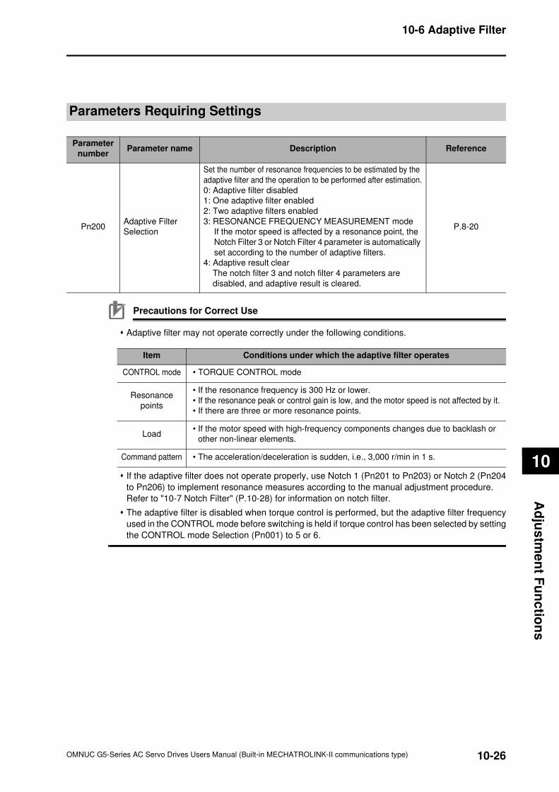
10-26
10-6 Adaptive Filter
OMNUC G5-Series AC Servo Drives Users Manual (Built-in MECHATROLINK-II communications type)
10
Ad
jus
tme
nt F
un
ctio
ns
Parameters Requiring Settings
Precautions for Correct Use
Adaptive filter may not operate correctly under the following conditions.
If the adaptive filter does not operate properly, use Notch 1 (Pn201 to Pn203) or Notch 2 (Pn204
to Pn206) to implement resonance measures according to the manual adjustment procedure.
Refer to "10-7 Notch Filter" (P.10-28) for information on notch filter.
The adaptive filter is disabled when torque control is performed, but the adaptive filter frequency
used in the CONTROL mode before switching is held if torque control has been selected by setting
the CONTROL mode Selection (Pn001) to 5 or 6.
Parameter
numberParameter name Description Reference
Pn200Adaptive Filter
Selection
Set the number of resonance frequencies to be estimated by the
adaptive filter and the operation to be performed after estimation.
0: Adaptive filter disabled
1: One adaptive filter enabled
2: Two adaptive filters enabled
3: RESONANCE FREQUENCY MEASUREMENT mode
If the motor speed is affected by a resonance point, the
Notch Filter 3 or Notch Filter 4 parameter is automatically
set according to the number of adaptive filters.
4: Adaptive result clear
The notch filter 3 and notch filter 4 parameters are
disabled, and adaptive result is cleared.
P.8-20
Item Conditions under which the adaptive filter operates
CONTROL mode • TORQUE CONTROL mode
Resonance
points
• If the resonance frequency is 300 Hz or lower.
• If the resonance peak or control gain is low, and the motor speed is not affected by it.
• If there are three or more resonance points.
Load• If the motor speed with high-frequency components changes due to backlash or
other non-linear elements.
Command pattern • The acceleration/deceleration is sudden, i.e., 3,000 r/min in 1 s.
10-27
10-6 Adaptive Filter
OMNUC G5-Series AC Servo Drives Users Manual (Built-in MECHATROLINK-II communications type)
10
Ad
justm
en
t F
un
cti
on
s
Operating Procedure
1. Set the Adaptive Filter Selection (Pn200).
Select an adaptive filter from 1 to 4 on the Adaptive Filter Selection (Pn200).
2. Start an actual operation.
Enter an operation command and start the actual operation.
3. The Notch Filters 3 and 4 are automatically set.
When the influence of resonance point appears in the motor speed, the parameters for the
Notch Filters 3 and 4 are set automatically in accordance with the number of adaptive filters.
Precautions for Correct Use
An unusual noise or vibration may occur until the adaptive filter stabilizes after startup,
immediately after the first servo ON, or when the Realtime Autotuning Machine Rigidity Selection
(Pn003) is increased, but this is not a problem if it disappears right away. If the vibration or unusual
noise, however, continues for three or more reciprocating operations, take the following measures
in the possible order.
• Write the parameters used during normal operation to the EEPROM.
• Lower the Realtime Autotuning Machine Rigidity Selection (Pn003).
• Disable the adaptive filter by setting the Adaptive Filter Selection (Pn200) to 0.
(Resetting of inertial estimation and adaptive operation)
• Manually set the notch filter.
If unusual noise or vibration occurred, the setting of Notch 3 (Pn207 to Pn209) or Notch 4 (Pn210
to Pn212) may have changed to an extreme value. In this case, set Adaptive Filter Selection
(Pn200) to 0 to disable the parameter and then set Notch 3 Frequency Setting (Pn207) and Notch
4 Frequency Setting (Pn210) to 5,000 (disabled). Next, enable Adaptive Filter Selection again.
Notch 3 Frequency Setting (Pn207) and Notch 4 Frequency Setting (Pn210) are written to the
EEPROM every 30 minutes. When the power supply is turned OFF and then turned ON again,
this data is used as the default settings to perform adaptive operation.
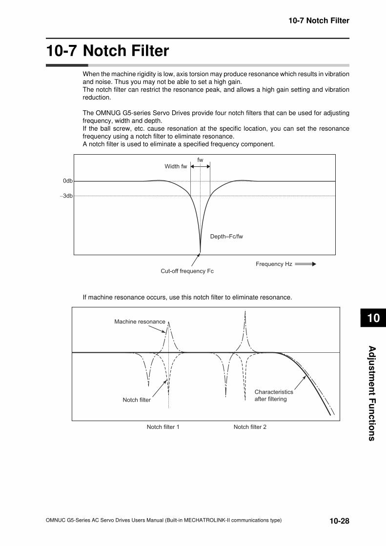
10-28
10-7 Notch Filter
OMNUC G5-Series AC Servo Drives Users Manual (Built-in MECHATROLINK-II communications type)
10
Ad
jus
tme
nt F
un
ctio
ns
10-7 Notch Filter
When the machine rigidity is low, axis torsion may produce resonance which results in vibration
and noise. Thus you may not be able to set a high gain.
The notch filter can restrict the resonance peak, and allows a high gain setting and vibration
reduction.
The OMNUG G5-series Servo Drives provide four notch filters that can be used for adjusting
frequency, width and depth.
If the ball screw, etc. cause resonation at the specific location, you can set the resonance
frequency using a notch filter to eliminate resonance.
A notch filter is used to eliminate a specified frequency component.
If machine resonance occurs, use this notch filter to eliminate resonance.
Depth=Fc/fw
Cut-off frequency Fc
Frequency Hz
Width fwfw
0db
−3db
Notch filter 1 Notch filter 2
Machine resonance
Notch filter
Characteristics
after filtering
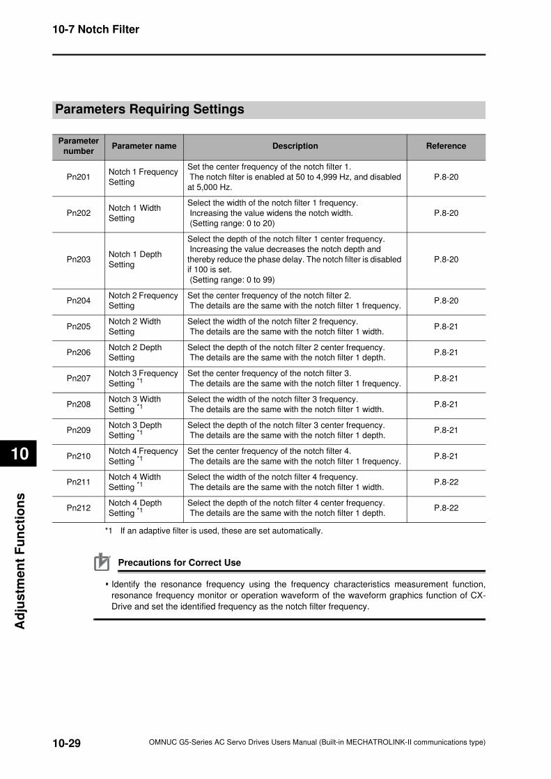
10-29
10-7 Notch Filter
OMNUC G5-Series AC Servo Drives Users Manual (Built-in MECHATROLINK-II communications type)
10
Ad
justm
en
t F
un
cti
on
s
Parameters Requiring Settings
*1 If an adaptive filter is used, these are set automatically.
Precautions for Correct Use
Identify the resonance frequency using the frequency characteristics measurement function,
resonance frequency monitor or operation waveform of the waveform graphics function of CX-
Drive and set the identified frequency as the notch filter frequency.
Parameter
numberParameter name Description Reference
Pn201Notch 1 Frequency
Setting
Set the center frequency of the notch filter 1.
The notch filter is enabled at 50 to 4,999 Hz, and disabled
at 5,000 Hz.
P.8-20
Pn202Notch 1 Width
Setting
Select the width of the notch filter 1 frequency.
Increasing the value widens the notch width.
(Setting range: 0 to 20)
P.8-20
Pn203Notch 1 Depth
Setting
Select the depth of the notch filter 1 center frequency.
Increasing the value decreases the notch depth and
thereby reduce the phase delay. The notch filter is disabled
if 100 is set.
(Setting range: 0 to 99)
P.8-20
Pn204Notch 2 Frequency
Setting
Set the center frequency of the notch filter 2.
The details are the same with the notch filter 1 frequency.P.8-20
Pn205Notch 2 Width
Setting
Select the width of the notch filter 2 frequency.
The details are the same with the notch filter 1 width.P.8-21
Pn206Notch 2 Depth
Setting
Select the depth of the notch filter 2 center frequency.
The details are the same with the notch filter 1 depth.P.8-21
Pn207Notch 3 Frequency
Setting *1Set the center frequency of the notch filter 3.
The details are the same with the notch filter 1 frequency.P.8-21
Pn208Notch 3 Width
Setting *1Select the width of the notch filter 3 frequency.
The details are the same with the notch filter 1 width.P.8-21
Pn209Notch 3 Depth
Setting *1Select the depth of the notch filter 3 center frequency.
The details are the same with the notch filter 1 depth.P.8-21
Pn210Notch 4 Frequency
Setting *1Set the center frequency of the notch filter 4.
The details are the same with the notch filter 1 frequency.P.8-21
Pn211Notch 4 Width
Setting *1Select the width of the notch filter 4 frequency.
The details are the same with the notch filter 1 width.P.8-22
Pn212Notch 4 Depth
Setting *1Select the depth of the notch filter 4 center frequency.
The details are the same with the notch filter 1 depth.P.8-22
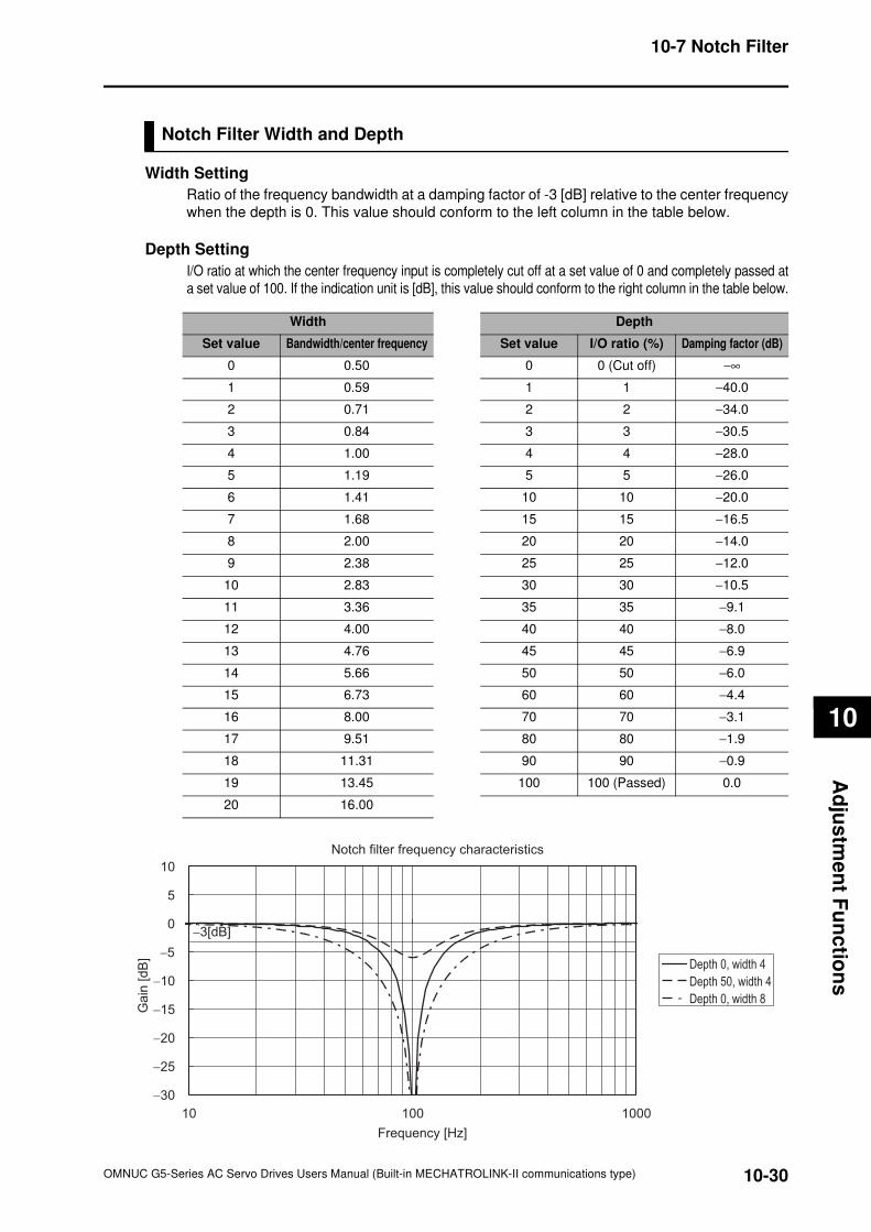
10-30
10-7 Notch Filter
OMNUC G5-Series AC Servo Drives Users Manual (Built-in MECHATROLINK-II communications type)
10
Ad
jus
tme
nt F
un
ctio
ns
Notch Filter Width and Depth
Width Setting
Ratio of the frequency bandwidth at a damping factor of -3 [dB] relative to the center frequency
when the depth is 0. This value should conform to the left column in the table below.
Depth Setting
I/O ratio at which the center frequency input is completely cut off at a set value of 0 and completely passed at
a set value of 100. If the indication unit is [dB], this value should conform to the right column in the table below.
Width Depth
Set value Bandwidth/center frequency Set value I/O ratio (%) Damping factor (dB)
0 0.50 0 0 (Cut off) −∞
1 0.59 1 1 −40.0
2 0.71 2 2 −34.0
3 0.84 3 3 −30.5
4 1.00 4 4 −28.0
5 1.19 5 5 −26.0
6 1.41 10 10 −20.0
7 1.68 15 15 −16.5
8 2.00 20 20 −14.0
9 2.38 25 25 −12.0
10 2.83 30 30 −10.5
11 3.36 35 35 −9.1
12 4.00 40 40 −8.0
13 4.76 45 45 −6.9
14 5.66 50 50 −6.0
15 6.73 60 60 −4.4
16 8.00 70 70 −3.1
17 9.51 80 80 −1.9
18 11.31 90 90 −0.9
19 13.45 100 100 (Passed) 0.0
20 16.00
Notch filter frequency characteristics
−30
−25
−20
−15
−10
−5
0
5
10
000100101
Frequency [Hz]
Ga
in [
dB
]
−3[dB]
Depth 0, width 4
Depth 50, width 4
Depth 0, width 8
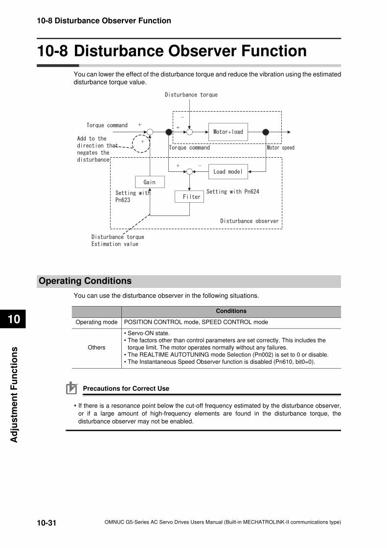
10-31
10-8 Disturbance Observer Function
OMNUC G5-Series AC Servo Drives Users Manual (Built-in MECHATROLINK-II communications type)
10
Ad
justm
en
t F
un
cti
on
s
10-8 Disturbance Observer Function
You can lower the effect of the disturbance torque and reduce the vibration using the estimated
disturbance torque value.
Operating Conditions
You can use the disturbance observer in the following situations.
Precautions for Correct Use
If there is a resonance point below the cut-off frequency estimated by the disturbance observer,
or if a large amount of high-frequency elements are found in the disturbance torque, the
disturbance observer may not be enabled.
Conditions
Operating mode POSITION CONTROL mode, SPEED CONTROL mode
Others
• Servo-ON state.
• The factors other than control parameters are set correctly. This includes the
torque limit. The motor operates normally without any failures.
• The REALTIME AUTOTUNING mode Selection (Pn002) is set to 0 or disable.
• The Instantaneous Speed Observer function is disabled (Pn610, bit0=0).
+
+
−
+ −
+
+
10-32
10-8 Disturbance Observer Function
OMNUC G5-Series AC Servo Drives Users Manual (Built-in MECHATROLINK-II communications type)
10
Ad
jus
tme
nt F
un
ctio
ns
Parameters Requiring Settings
Operating Procedure
1. Set the Function Expansion Setting (Pn610).
Set whether to enable or disable the disturbance observer in bit 1.
0: Disabled
1: Enabled
Set the operating conditions to be enabled in bit 2.
0: Enabled at all time
1: Enabled only when gain 1 is selected
2. Set the Disturbance Observer Filter Setting (Pn624).
Set a small value to the Disturbance Torque Compensation Gain (Pn623).
Change the value on the Disturbance Observer Filter Setting (Pn624) from a large value
gradually to a smaller one.
The smaller the value set on the Disturbance Observer Filter Setting (Pn624) is, the lesser
disturbance torque lag can be estimated, and the more effective the disturbance influence can
be controlled. But the smaller the value is, the larger the operation noise can be. You must
consider the balance of these advantage and disadvantage to set a value.
3. Set the Disturbance Torque Compensation Gain (Pn623).
After you set the Disturbance Observer Filter Setting (Pn624), return the value on the
Disturbance Torque Compensation Gain (Pn623) from the small value to a large value. The
larger the value set on the Disturbance Torque Compensation Gain (Pn623) is, the more
effective the disturbance influence can be controlled. But the larger the value is, the larger the
operation noise can be. You must consider the balance of these advantage and disadvantage
to set a value.
Parameter
numberParameter name Description Reference
Pn610 Function Expansion Setting Set the bits related to the disturbance observer. P.8-53
Pn623Disturbance Torque
Compensation Gain
Set the compensation gain for disturbance
torque.P.8-55
Pn624Disturbance Observer Filter
Setting
Set the filter time constant for disturbance torque
compensation.P.8-55
10-33
10-9 Friction Torque Compensation Function
OMNUC G5-Series AC Servo Drives Users Manual (Built-in MECHATROLINK-II communications type)
10
Ad
justm
en
t F
un
cti
on
s
10-9 Friction Torque Compensation Function
Two types of friction torque compensations can be set to reduce influence of mechanical
frictions. One is the unbalanced load compensation that offsets the constantly applied
unbalance torque. The other is the dynamic friction compensation that changes the offset
direction in accordance with the operating direction.
Operating Conditions
You can use the function under the following conditions:
Parameters Requiring Settings
The torque compensation function needs the combined settings of following three parameters.
Conditions
• Servo-ON state.
• The factors other than control parameters are set correctly. This includes the torque limit. The motor
operates normally without any failures.
Parameter
numberParameter name Description Reference
Pn607Torque Command Value
Offset
Set the unbalanced load compensation value that
is always added to the torque command in the
CONTROL mode other than torque control.
P.8-52
Pn608Forward Direction Torque
Offset
Set the dynamic friction compensation value that is
added to the torque command when a forward
direction position command is input for position
control or full closing control.
P.8-52
Pn609Reverse Direction Torque
Offset
Set the dynamic friction compensation value that is
added to the torque command when a reverse
direction position command is input for position
control or full closing control.
P.8-53
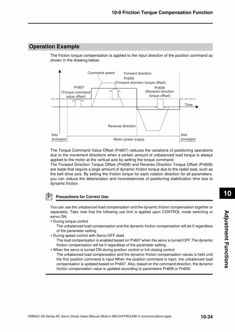
10-34
10-9 Friction Torque Compensation Function
OMNUC G5-Series AC Servo Drives Users Manual (Built-in MECHATROLINK-II communications type)
10
Ad
jus
tme
nt F
un
ctio
ns
Operation Example
The friction torque compensation is applied to the input direction of the position command as
shown in the drawing below.
The Torque Command Value Offset (Pn607) reduces the variations of positioning operations
due to the movement directions when a certain amount of unbalanced load torque is always
applied to the motor at the vertical axis by setting the torque command.
The Forward Direction Torque Offset (Pn608) and Reverse Direction Torque Offset (Pn609)
are loads that require a large amount of dynamic friction torque due to the radial load, such as
the belt drive axis. By setting the friction torque for each rotation direction for all parameters,
you can reduce the deterioration and inconsistencies of positioning stabilization time due to
dynamic friction.
Precautions for Correct Use
You can use the unbalanced load compensation and the dynamic friction compensation together or
separately. Take note that the following use limit is applied upon CONTROL mode switching or
servo ON.
During torque control
The unbalanced load compensation and the dynamic friction compensation will be 0 regardless
of the parameter setting.
During speed control with Servo-OFF state
The load compensation is enabled based on Pn607 when the servo is turned OFF.The dynamic
friction compensation will be 0 regardless of the parameter setting.
When the servo is turned ON during position control or full closing control
The unbalanced load compensation and the dynamic friction compensation values is held until
the first position command is input.When the position command is input, the unbalanced load
compensation is updated based on Pn607. Also, based on the command direction, the dynamic
friction compensation value is updated according to parameters Pn608 or Pn609.
Command speed
Time
Motor
de-energized
Motor
de-energized Motor power supply
Pn607
(Torque command
value offset)
Forward direction
Reverse direction
Pn608 (Forward direction torque offset)
Pn609 (Reverse direction
torque offset)
10-35
10-10 Hybrid Vibration Suppression Function
OMNUC G5-Series AC Servo Drives Users Manual (Built-in MECHATROLINK-II communications type)
10
Ad
justm
en
t F
un
cti
on
s
10-10 Hybrid Vibration Suppression Function
This function suppresses the vibrations that are caused by the amount of the torsion between
the motor and the load in the FULL CLOSING CONTROL mode.You can use this function to
raise the gain setting.
Operating Conditions
The hybrid vibration suppression function can be used in the following situations.
Parameters Requiring Settings
Operating Procedure
1. Set the Hybrid Vibration Suppression Gain (Pn634) to the same value as the positionloop gain.
2. Gradually increase the set value of the Hybrid Vibration Suppression Filter (Pn635)
while driving with full closing control and check the changes in the response.
If the response improves, find the combination of Pn634 and Pn635 that result in the optimal
response by adjusting them.
Precautions for Correct Use
This function is effective when the amount of torsion between the motor shaft and the load is
large.This may be less effective when the amount of torsion is small.
Conditions
Operating mode FULL CLOSING CONTROL mode
Others
• Servo-ON state.
• The factors other than control parameters are set correctly. This includes the
torque limit. The motor operates normally without any failures.
Parameter
numberParameter name Description Reference
Pn634
Hybrid Vibration
Suppression Gain
Set the hybrid vibration suppression gain.
In general, set it to the same value as the position
loop gain, and finely adjust it based on the
situation.
P.8-57
Pn635Hybrid Vibration
Suppression Filter
Set the hybrid vibration suppression filter.P.8-58
10-36
10-11 Feed-forward Function
OMNUC G5-Series AC Servo Drives Users Manual (Built-in MECHATROLINK-II communications type)
10
Ad
jus
tme
nt F
un
ctio
ns
10-11 Feed-forward Function
The feed-forward function come in 2 types: speed feed forward and torque feed forward.
The speed feed forward can minimize the position error and increase the responsiveness by
calculating the speed control command that is required for the operation based on the internal
positioning command during position or full closing control, and adding it to the speed
command that is calculated based on the comparison with the position feedback.
The torque feed forward can increase the responsiveness during speed control by calculating
the torque command that is required for the operation based on the speed control command,
and adding it to the torque command that is calculated based on the comparison with the
speed feedback.
Parameters Requiring Settings
Parameter
numberParameter name Description Reference
Pn110Speed Feed-forward
Amount
Use this parameter to add the speed control
command calculated from the internal positioning
command that is multiplied by this parameter's ratio
to the speed command from the position control
process.
P.8-11
Pn111Speed Feed-forward
Command Filter
Set the time constant for the first-order lag filter that
is applied to speed feed-forward inputs.P.8-11
Pn112Torque Feed-forward
Amount
Use this parameter to add the torque command
calculated from the speed control command that is
multiplied by this parameter's ratio to the torque
command from the speed control process.
P.8-11
Pn113Torque Feed-forward
Command Filter
Set the time constant for the first-order lag filter that
is applied to torque feed-forward inputs.P.8-11
Pn610 Function Expansion Setting Set the bits related to inertia ratio switching. P.8-53
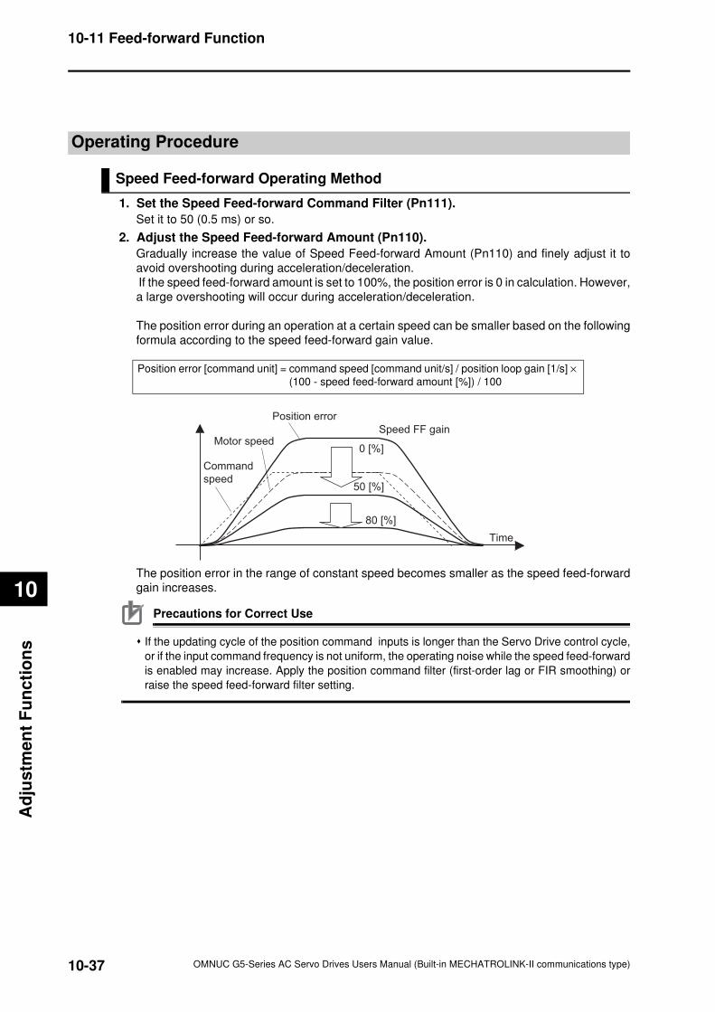
10-37
10-11 Feed-forward Function
OMNUC G5-Series AC Servo Drives Users Manual (Built-in MECHATROLINK-II communications type)
10
Ad
justm
en
t F
un
cti
on
s
Operating Procedure
Speed Feed-forward Operating Method
1. Set the Speed Feed-forward Command Filter (Pn111).
Set it to 50 (0.5 ms) or so.
2. Adjust the Speed Feed-forward Amount (Pn110).
Gradually increase the value of Speed Feed-forward Amount (Pn110) and finely adjust it to
avoid overshooting during acceleration/deceleration.
If the speed feed-forward amount is set to 100%, the position error is 0 in calculation. However,
a large overshooting will occur during acceleration/deceleration.
The position error during an operation at a certain speed can be smaller based on the following
formula according to the speed feed-forward gain value.
The position error in the range of constant speed becomes smaller as the speed feed-forward
gain increases.
Precautions for Correct Use
If the updating cycle of the position command inputs is longer than the Servo Drive control cycle,
or if the input command frequency is not uniform, the operating noise while the speed feed-forward
is enabled may increase. Apply the position command filter (first-order lag or FIR smoothing) or
raise the speed feed-forward filter setting.
Position error [command unit] = command speed [command unit/s] / position loop gain [1/s] ×
(100 - speed feed-forward amount [%]) / 100
Command
speed
Motor speed
Position error
Speed FF gain
50 [%]
80 [%]
0 [%]
Time
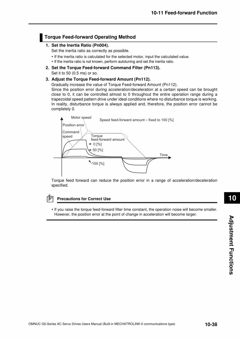
10-38
10-11 Feed-forward Function
OMNUC G5-Series AC Servo Drives Users Manual (Built-in MECHATROLINK-II communications type)
10
Ad
jus
tme
nt F
un
ctio
ns
Torque Feed-forward Operating Method
1. Set the Inertia Ratio (Pn004).
Set the inertia ratio as correctly as possible.
If the inertia ratio is calculated for the selected motor, input the calculated value.
If the inertia ratio is not known, perform autotuning and set the inertia ratio.
2. Set the Torque Feed-forward Command Filter (Pn113).
Set it to 50 (0.5 ms) or so.
3. Adjust the Torque Feed-forward Amount (Pn112).
Gradually increase the value of Torque Feed-forward Amount (Pn112).
Since the position error during acceleration/deceleration at a certain speed can be brought
close to 0, it can be controlled almost to 0 throughout the entire operation range during a
trapezoidal speed pattern drive under ideal conditions where no disturbance torque is working.
In reality, disturbance torque is always applied and, therefore, the position error cannot be
completely 0.
Torque feed forward can reduce the position error in a range of acceleration/deceleration
specified.
Precautions for Correct Use
If you raise the torque feed-forward filter time constant, the operation noise will become smaller.
However, the position error at the point of change in acceleration will become larger.
Command
speed
Motor speed
Position error
Speed feed-forward amount = fixed to 100 [%]
100 [%]
0 [%]
Torquefeed-forward amount
50 [%]
Time
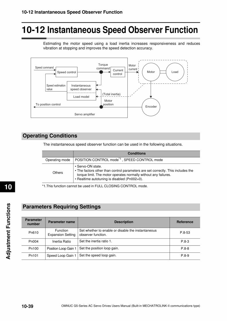
10-39
10-12 Instantaneous Speed Observer Function
OMNUC G5-Series AC Servo Drives Users Manual (Built-in MECHATROLINK-II communications type)
10
Ad
justm
en
t F
un
cti
on
s
10-12 Instantaneous Speed Observer Function
Estimating the motor speed using a load inertia increases responsiveness and reduces
vibration at stopping and improves the speed detection accuracy.
Operating Conditions
The instantaneous speed observer function can be used in the following situations.
Parameters Requiring Settings
Current
controlSpeed control
Speed command
Speed estimation
value
Torque
command
Instantaneous
speed observer
Load model
Motor
currentMotor
Encoder
Servo amplifier
Motor
positionTo position control
Load
(Total inertia)
Conditions
Operating mode POSITION CONTROL mode*1 , SPEED CONTROL mode
*1.This function cannot be used in FULL CLOSING CONTROL mode.
Others
• Servo-ON state.
• The factors other than control parameters are set correctly. This includes the
torque limit. The motor operates normally without any failures.
• Realtime autotuning is disabled (Pn002=0).
Parameter
numberParameter name Description Reference
Pn610Function
Expansion Setting
Set whether to enable or disable the instantaneous
observer function.P.8-53
Pn004 Inertia Ratio Set the inertia ratio 1. P.8-3
Pn100 Position Loop Gain 1 Set the position loop gain. P.8-8
Pn101 Speed Loop Gain 1 Set the speed loop gain. P.8-9
10-40
10-12 Instantaneous Speed Observer Function
OMNUC G5-Series AC Servo Drives Users Manual (Built-in MECHATROLINK-II communications type)
10
Ad
jus
tme
nt F
un
ctio
ns
Operating Procedure
1. Set the Inertia Ratio (Pn004).
Set the inertia ratio as correctly as possible. If the Inertia Ratio (Pn004) is obtained in a realtime auto gain tuning, use the set value.
If the inertia ratio is calculated for the selected motor, input the calculated value.
If the inertia ratio is not known, perform autotuning and set the inertia ratio.
2. Adjust the position loop gain and speed loop gain.
Adjust Position Loop Gain 1 (Pn100), Speed Loop Gain 1 (Pn101), Speed Loop Integral Time
Constant 1 (Pn102) and Torque Command Filter Time Constant 1 (Pn104).
If no problem occurs in realtime autotuning, you can continue to use the settings.
3. Set the Function Expansion Setting (Pn610).
Set whether to enable or disable the instantaneous speed observer function in bit 0.
If you set this to 1 (enabled), the speed detection method switches to instantaneous speed
observer. If the machine operation noise or vibration, or a change in the torque monitor waveform is
significant enough to cause any problem, return the setting to 0 and make sure that the inertia ratio
or the adjustment parameters are correct.
If the machine operation noise or vibration, or a change in the torque monitor waveform is small,
make small adjustments to the Inertia Ratio (Pn004) to find the setting that makes the smallest
change while monitoring the position error waveform and the actual speed waveform.
If Position Loop Gain 1 (Pn100), Speed Loop Gain 1 (Pn101) or Speed Loop Integral Time
Constant 1 (Pn102) is changed, the optimal value for the Inertia Ratio (Pn004) may change, so
make small adjustments on the value for the Inertia Ratio (Pn004) again to set a value that makes
the smallest change.
Precautions for Correct Use
It may not function properly or the effect may not be apparent under the following conditions.
• If the margin of error with the actual device is large for the inertia load.
• If there are multiple resonance points.
• If there is a large resonance point at the frequency of 300 Hz or lower.
• If there is a non-linear element (play), such as a large backlash.
• If the load inertia changes.
• If a large disturbance torque with high-frequency elements is applied.
• If the setting range for positioning is small.

OMNUC G5-Series AC Servo Drives Users Manual (Built-in MECHATROLINK-II communications type)
11
11This chapter explains the items to check when problems occur, error diagnosis
using the alarm LED display and measures, error diagnosis based on the
operating condition and measures, and periodic maintenance.
11-1 Error Processing.........................................................11-1
11-2 Warning .......................................................................11-4
11-3 Alarms..........................................................................11-6
11-4 Troubleshooting .......................................................11-16
11-5 Periodic Maintenance...............................................11-36
Error and Maintenance
11-1
11-1 Error Processing
OMNUC G5-Series AC Servo Drives Users Manual (Built-in MECHATROLINK-II communications type)
11
Err
or
an
d M
ain
ten
an
ce
11-1 Error Processing
Preliminary Checks When a Problem Occurs
This section explains the preliminary checks and analytical softwares required to determine the
cause of a problem if one occurs.
Checking the Power Supply Voltage
Check the voltage at the power supply input terminals.
Main circuit power supply input terminal (L1, L2, L3)
R88D-KNxL-ML2 (50 to 400 W) : Single-phase 100 to 120 VAC (85 to 132 V) 50/60 Hz
R88D-KNxH-ML2 (100 W to 1.5 kW) : Single-phase 200 to 240 VAC (170 to 264 V) 50/60 Hz
(750 W to 1.5 kW) : 3-phase 200 to 240 VAC (170 to 264 V) 50/60 Hz
(2 to 5 kW) : 3-phase 200 to 230 VAC (170 to 253 V) 50/60 Hz
R88D-KNxF-ML2 (750 W to 5 kW) : 3-phase 380 to 480 VAC (323 to 528 V) 50/60 Hz
Control circuit power supply input terminal (L1C, L2C)
R88D-KNxL-ML2 (50 to 400 W) : Single-phase 100 to 120 VAC (85 to 132 V) 50/60 Hz
R88D-KNxH-ML2 (100 W to 1.5 kW) : Single-phase 200 to 240 VAC (170 to 264 V) 50/60 Hz
(2 to 5 kW) : Single-phase 200 to 230 VAC (170 to 253 V) 50/60 Hz
R88D-KNxF-ML2 (750 W to 5 kW) : 24 VDC (21.6 to 26.4 V)
If the voltage is out of this range, there is a risk of operation failure, so be sure that the power
supply is correct.
Check the voltage of the sequence input power supply. (+24 VIN terminal (CN1 pin 7))
Within the range of 11 to 25 VDC.
If the voltage is out of this range, there is a risk of operation failure. Be sure that the power supply
is correct.
Checking Whether an Alarm Has Occurred
Make an analysis using the 7-segment LED display area in the front of the Servo Drive and using
the Operation keys.
When an alarm has occurred
… Check the alarm display that displays (xx) and make an analysis based on the alarm that is indicated.
When an alarm has not occurred
… Make an analysis according to the error conditions.
In either case, refer to "11-4 Troubleshooting (P.11-16)" for details.
11-2
11-1 Error Processing
OMNUC G5-Series AC Servo Drives Users Manual (Built-in MECHATROLINK-II communications type)
11
Erro
r an
d M
ain
ten
an
ce
Precautions When a Problem Occurs
When checking and verifying I/O after a problem has occurred, the Servo Drive may suddenly
start to operate or suddenly stop, so always take the following precautions.
You should assure that anything not described in this manual is not possible with this product.
Precautions
Disconnect the wire before checking for cable breakage. Even if you test conduction with the cable
connected, test results may not be accurate due to conduction via bypassing circuit.
If the encoder signal is lost, the motor may run away, or an error may occur. Be sure to disconnect
the motor from the mechanical system before checking the encoder signal.
When measuring the encoder output, perform the measurement based on the GND (CN1 pin 16).
When an oscilloscope is used for measurement, it will not be affected by noise if measurements
are performed using the differential between CH1 and CH2.
When performing tests, first check that there are no persons in the vicinity of the equipment, and
that the equipment will not be damaged even if the motor runs away.
Before performing the tests, verify that you can immediately stop the machine using an emergency
stop even if it runs away.
11-3
11-1 Error Processing
OMNUC G5-Series AC Servo Drives Users Manual (Built-in MECHATROLINK-II communications type)
11
Err
or
an
d M
ain
ten
an
ce
Replacing the Servomotor and Servo Drive
Use the following procedure to replace the Servomotor or Servo Drive.
Replacing the Servomotor
1. Replace the motor.
2. Perform origin adjustment (for position control).
When the motor is replaced, the motor's origin position (phase Z) may deviate, so origin
adjustment must be performed.
Refer to the Position Controller's manual for details on performing origin adjustment.
3. Set up the absolute encoder.
If a motor with an absolute encoder is used, the absolute value data in the absolute encoder is
cleared when the motor is replaced, so setup is again required.
The multi-rotation data will be different from before it was replaced, so reset the initial Motion
Control Unit parameters.
For details, refer to "Absolute Encoder Setup" (P.9-6).
Replacing the Servo Drive
1. Copy the parameters.
Use the CX-Drive software tool to write down all the contents of parameter settings.
2. Replace the Servo Drive.
3. Set the parameters.
Use the CX-Drive software tool to set all the parameters.
4. Set up the absolute encoder.
If a motor with an absolute encoder is used, the absolute value data in the absolute encoder is
cleared when the Servo Drive is replaced, so setup is again required.
The multi-rotation data will be different from before it was replaced, so reset the initial Motion
Control Unit parameters.
For details, refer to "Absolute Encoder Setup" (P.9-6).
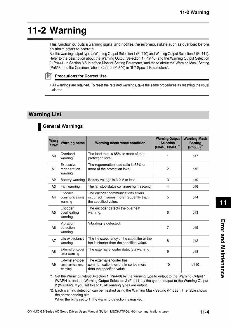
11-4
11-2 Warning
OMNUC G5-Series AC Servo Drives Users Manual (Built-in MECHATROLINK-II communications type)
11
Erro
r an
d M
ain
ten
an
ce
11-2 Warning
This function outputs a warning signal and notifies the erroneous state such as overload before
an alarm starts to operate.
Set the warning output type to Warning Output Selection 1 (Pn440) and Waning Output Selection 2 (Pn441).
Refer to the description about the Warning Output Selection 1 (Pn440) and the Warning Output Selection
2 (Pn441) in Section 8-5 Interface Monitor Setting Parameter, and those about the Warning Mask Setting
(Pn638) and the Communications Control (Pn800) in “8-7 Special Parameters”.
Precautions for Correct Use
All warnings are retained. To reset the retained warnings, take the same procedures as resetting the usual
alarms.
Warning List
General Warnings
*1. Set the Warning Output Selection 1 (Pn440) by the warning type to output to the Warning Output 1
(WARN1), and the Warning Output Selection 2 (Pn441) by the type to output to the Warning Output
2 (WARN2). If you set this to 0, all warning types are output.
*2. Each warning detection can be masked using the Warning Mask Setting (Pn638). The table shows
the corresponding bits.
When the bit is set to 1, the warning detection is masked.
Warning
numberWarning name Warning occurrence condition
Warning Output
Selection
(Pn440, Pn441) *1
Warning Mask
Setting
(Pn638)*2
A0Overload
warning
The load ratio is 85% or more of the
protection level.1 bit7
A1
Excessive
regeneration
warning
The regeneration load ratio is 85% or
more of the protection level. 2 bit5
A2 Battery warning Battery voltage is 3.2 V or less. 3 bit0
A3 Fan warning The fan stop status continues for 1 second. 4 bit6
A4
Encoder
communications
warning
The encoder communications errors
occurred in series more frequently than
the specified value.
5 bit4
A5
Encoder
overheating
warning
The encoder detects the overheat
warning. 6 bit3
A6
Vibration
detection
warning
Vibrating is detected.
7 bit9
A7Life expectancy
warning
The life expectancy of the capacitor or the
fan is shorter than the specified value.8 bit2
A8External encoder
error warning
The external encoder detects a warning.9 bit8
A9
External encoder
communications
warning
The external encoder has
communications errors in series more
than the specified value.
10 bit10
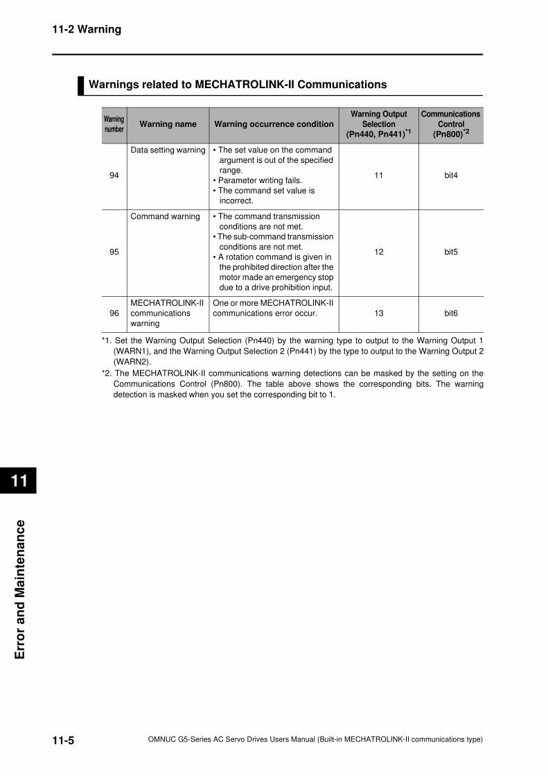
11-5
11-2 Warning
OMNUC G5-Series AC Servo Drives Users Manual (Built-in MECHATROLINK-II communications type)
11
Err
or
an
d M
ain
ten
an
ce
Warnings related to MECHATROLINK-II Communications
Warning
numberWarning name Warning occurrence condition
Warning Output
Selection
(Pn440, Pn441)*1
Communications
Control
(Pn800)*2
94
Data setting warning • The set value on the command
argument is out of the specified
range.
• Parameter writing fails.
• The command set value is
incorrect.
11 bit4
95
Command warning • The command transmission
conditions are not met.
• The sub-command transmission
conditions are not met.
• A rotation command is given in
the prohibited direction after the
motor made an emergency stop
due to a drive prohibition input.
12 bit5
96
MECHATROLINK-II
communications
warning
One or more MECHATROLINK-II
communications error occur. 13 bit6
*1. Set the Warning Output Selection (Pn440) by the warning type to output to the Warning Output 1
(WARN1), and the Warning Output Selection 2 (Pn441) by the type to output to the Warning Output 2
(WARN2).
*2. The MECHATROLINK-II communications warning detections can be masked by the setting on the
Communications Control (Pn800). The table above shows the corresponding bits. The warning
detection is masked when you set the corresponding bit to 1.
11-6
11-3 Alarms
OMNUC G5-Series AC Servo Drives Users Manual (Built-in MECHATROLINK-II communications type)
11
Erro
r an
d M
ain
ten
an
ce
11-3 Alarms
If the Servo Drive detects an error, it outputs an alarm (ALM), turns off the power drive circuit,
and displays the error number on the front panel.
Precautions for Correct Use
Refer to "Error Diagnosis Using the Alarm Displays" (P.11-16) for appropriate alarm measures.
Reset the alarm using one of the following methods. Remove the cause of the alarm first.
• Turn OFF the power supply, then turn it ON again.
• Reset the alarm via MECHATROLINK-II communications or on CX-Drive.
However, some alarms can only be reset by turning the power supply OFF then ON again. Refer
to the "Alarm List" (P.11-7).
If you reset an alarm while the operation command (RUN) is turned ON, the Servo Drive starts
operation as soon as the alarm is released, which is dangerous. Be sure to turn OFF the RUN
before clearing the alarm.
If the RUN is always ON, first check safety sufficiently before clearing the alarm.
The Overload (Alarm No.16) cannot be reset for 10 seconds once it occurs.
Any displays such as hh, FF, and HH on the error number mean internal malfunction on the MPU.
Cut off the power immediately when you encounter such a case.
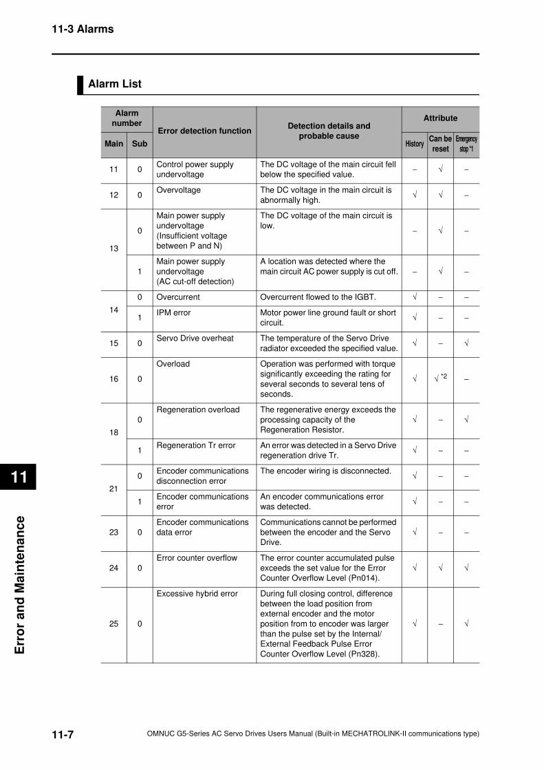
11-7
11-3 Alarms
OMNUC G5-Series AC Servo Drives Users Manual (Built-in MECHATROLINK-II communications type)
11
Err
or
an
d M
ain
ten
an
ce
Alarm List
Alarm
numberError detection function
Detection details and
probable cause
Attribute
Main Sub HistoryCan be
reset
Emergency
stop *1
11 0Control power supply
undervoltage
The DC voltage of the main circuit fell
below the specified value.− √ −
12 0Overvoltage The DC voltage in the main circuit is
abnormally high.√ √ −
13
0
Main power supply
undervoltage
(Insufficient voltage
between P and N)
The DC voltage of the main circuit is
low.− √ −
1
Main power supply
undervoltage
(AC cut-off detection)
A location was detected where the
main circuit AC power supply is cut off. − √ −
14
0 Overcurrent Overcurrent flowed to the IGBT. √ − −
1IPM error Motor power line ground fault or short
circuit.√ − −
15 0Servo Drive overheat The temperature of the Servo Drive
radiator exceeded the specified value.√ − √
16 0
Overload Operation was performed with torque
significantly exceeding the rating for
several seconds to several tens of
seconds.
√ √ *2
−
18
0
Regeneration overload The regenerative energy exceeds the
processing capacity of the
Regeneration Resistor.
√ − √
1Regeneration Tr error An error was detected in a Servo Drive
regeneration drive Tr.√ − −
21
0Encoder communications
disconnection error
The encoder wiring is disconnected.√ − −
1Encoder communications
error
An encoder communications error
was detected.√ − −
23 0
Encoder communications
data error
Communications cannot be performed
between the encoder and the Servo
Drive.
√ − −
24 0
Error counter overflow The error counter accumulated pulse
exceeds the set value for the Error
Counter Overflow Level (Pn014).
√ √ √
25 0
Excessive hybrid error During full closing control, difference
between the load position from
external encoder and the motor
position from to encoder was larger
than the pulse set by the Internal/
External Feedback Pulse Error
Counter Overflow Level (Pn328).
√ − √
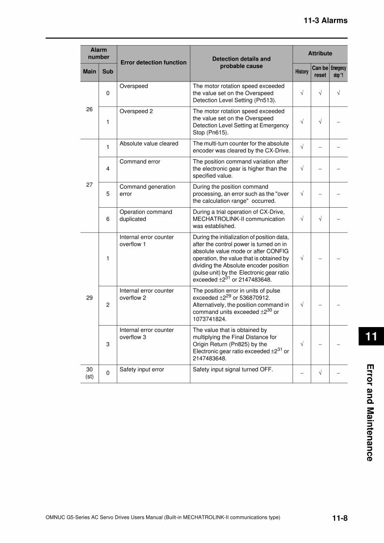
11-8
11-3 Alarms
OMNUC G5-Series AC Servo Drives Users Manual (Built-in MECHATROLINK-II communications type)
11
Erro
r an
d M
ain
ten
an
ce
26
0
Overspeed The motor rotation speed exceeded
the value set on the Overspeed
Detection Level Setting (Pn513).
√ √ √
1
Overspeed 2 The motor rotation speed exceeded
the value set on the Overspeed
Detection Level Setting at Emergency
Stop (Pn615).
√ √ −
27
1Absolute value cleared The multi-turn counter for the absolute
encoder was cleared by the CX-Drive.√ − −
4
Command error The position command variation after
the electronic gear is higher than the
specified value.
√ − −
5
Command generation
error
During the position command
processing, an error such as the "over
the calculation range" occurred.
√ − −
6
Operation command
duplicated
During a trial operation of CX-Drive,
MECHATROLINK-II communication
was established.
√ √ −
29
1
Internal error counter
overflow 1
During the initialization of position data,
after the control power is turned on in
absolute value mode or after CONFIG
operation, the value that is obtained by
dividing the Absolute encoder position
(pulse unit) by the Electronic gear ratio
exceeded ±231 or 2147483648.
√ − −
2
Internal error counter
overflow 2
The position error in units of pulse
exceeded ±229 or 536870912.
Alternatively, the position command in
command units exceeded ±230 or
1073741824.
√ − −
3
Internal error counter
overflow 3
The value that is obtained by
multiplying the Final Distance for
Origin Return (Pn825) by the
Electronic gear ratio exceeded ±231 or
2147483648.
√ − −
30
(st)0
Safety input error Safety input signal turned OFF.− √ −
Alarm
numberError detection function
Detection details and
probable cause
Attribute
Main Sub HistoryCan be
reset
Emergency
stop *1
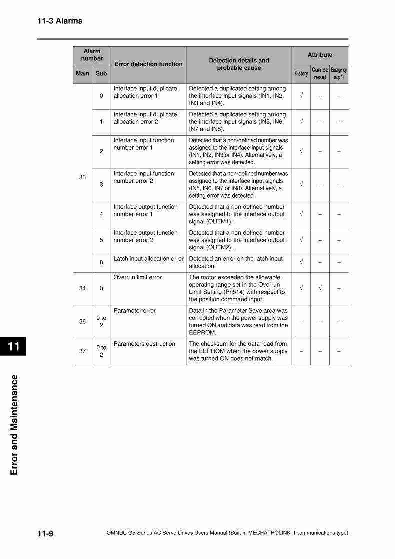
11-9
11-3 Alarms
OMNUC G5-Series AC Servo Drives Users Manual (Built-in MECHATROLINK-II communications type)
11
Err
or
an
d M
ain
ten
an
ce
33
0
Interface input duplicate
allocation error 1
Detected a duplicated setting among
the interface input signals (IN1, IN2,
IN3 and IN4).
√ − −
1
Interface input duplicate
allocation error 2
Detected a duplicated setting among
the interface input signals (IN5, IN6,
IN7 and IN8).
√ − −
2
Interface input function
number error 1
Detected that a non-defined number was
assigned to the interface input signals
(IN1, IN2, IN3 or IN4). Alternatively, a
setting error was detected.
√ − −
3
Interface input function
number error 2
Detected that a non-defined number was
assigned to the interface input signals
(IN5, IN6, IN7 or IN8). Alternatively, a
setting error was detected.
√ − −
4
Interface output function
number error 1
Detected that a non-defined number
was assigned to the interface output
signal (OUTM1).
√ − −
5
Interface output function
number error 2
Detected that a non-defined number
was assigned to the interface output
signal (OUTM2).
√ − −
8Latch input allocation error Detected an error on the latch input
allocation.√ − −
34 0
Overrun limit error The motor exceeded the allowable
operating range set in the Overrun
Limit Setting (Pn514) with respect to
the position command input.
√ √ −
360 to
2
Parameter error Data in the Parameter Save area was
corrupted when the power supply was
turned ON and data was read from the
EEPROM.
− − −
370 to
2
Parameters destruction The checksum for the data read from
the EEPROM when the power supply
was turned ON does not match.
− − −
Alarm
numberError detection function
Detection details and
probable cause
Attribute
Main Sub HistoryCan be
reset
Emergency
stop *1
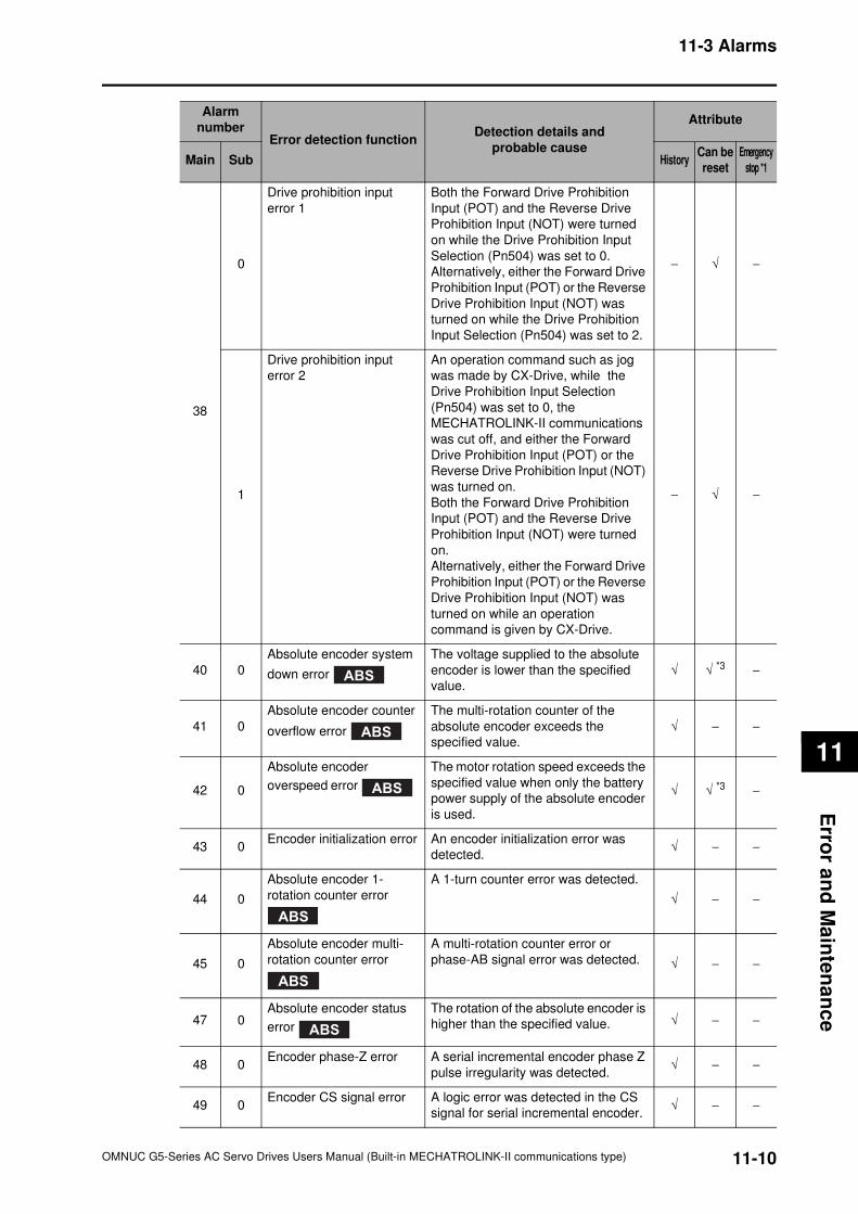
11-10
11-3 Alarms
OMNUC G5-Series AC Servo Drives Users Manual (Built-in MECHATROLINK-II communications type)
11
Erro
r an
d M
ain
ten
an
ce
38
0
Drive prohibition input
error 1
Both the Forward Drive Prohibition
Input (POT) and the Reverse Drive
Prohibition Input (NOT) were turned
on while the Drive Prohibition Input
Selection (Pn504) was set to 0.
Alternatively, either the Forward Drive
Prohibition Input (POT) or the Reverse
Drive Prohibition Input (NOT) was
turned on while the Drive Prohibition
Input Selection (Pn504) was set to 2.
− √ −
1
Drive prohibition input
error 2
An operation command such as jog
was made by CX-Drive, while the
Drive Prohibition Input Selection
(Pn504) was set to 0, the
MECHATROLINK-II communications
was cut off, and either the Forward
Drive Prohibition Input (POT) or the
Reverse Drive Prohibition Input (NOT)
was turned on.
Both the Forward Drive Prohibition
Input (POT) and the Reverse Drive
Prohibition Input (NOT) were turned
on.
Alternatively, either the Forward Drive
Prohibition Input (POT) or the Reverse
Drive Prohibition Input (NOT) was
turned on while an operation
command is given by CX-Drive.
− √ −
40 0
Absolute encoder system
down error
The voltage supplied to the absolute
encoder is lower than the specified
value.
√ √ *3
−
41 0
Absolute encoder counter
overflow error
The multi-rotation counter of the
absolute encoder exceeds the
specified value.
√ − −
42 0
Absolute encoder
overspeed error
The motor rotation speed exceeds the
specified value when only the battery
power supply of the absolute encoder
is used.
√ √ *3
−
43 0Encoder initialization error An encoder initialization error was
detected.√ − −
44 0
Absolute encoder 1-
rotation counter error
A 1-turn counter error was detected.
√ − −
45 0
Absolute encoder multi-
rotation counter error
A multi-rotation counter error or
phase-AB signal error was detected. √ − −
47 0Absolute encoder status
error
The rotation of the absolute encoder is
higher than the specified value. √ − −
48 0Encoder phase-Z error A serial incremental encoder phase Z
pulse irregularity was detected.√ − −
49 0Encoder CS signal error A logic error was detected in the CS
signal for serial incremental encoder.√ − −
Alarm
numberError detection function
Detection details and
probable cause
Attribute
Main Sub HistoryCan be
reset
Emergency
stop *1
ABS
ABS
ABS
ABS
ABS
ABS
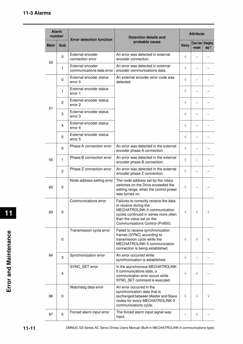
11-11
11-3 Alarms
OMNUC G5-Series AC Servo Drives Users Manual (Built-in MECHATROLINK-II communications type)
11
Err
or
an
d M
ain
ten
an
ce
50
0External encoder
connection error
An error was detected in external
encoder connection.√ − −
1External encoder
communications data error
An error was detected in external
encoder communications data.√ − −
51
0External encoder status
error 0
An external encoder error code was
detected.√ − −
1External encoder status
error 1√ − −
2External encoder status
error 2√ − −
3External encoder status
error 3√ − −
4External encoder status
error 4√ − −
5External encoder status
error 5√ − −
55
0Phase-A connection error An error was detected in the external
encoder phase A connection.√ − −
1Phase-B connection error An error was detected in the external
encoder phase B connection.√ − −
2Phase-Z connection error An error was detected in the external
encoder phase Z connection.√ − −
82 0
Node address setting error The node address set by the rotary
switches on the Drive exceeded the
setting range, when the control power
was turned on.
√ − −
83 0
Communications error Failures to correctly receive the data
to receive during the
MECHATROLINK-II communication
cycles continued in series more often
than the value set on the
Communications Control (Pn800).
√ √ √
84
0
Transmission cycle error Failed to receive synchronization
frames (SYNC) according to
transmission cycle while the
MECHATROLINK-II communication
connection is being established.
√ √ √
3Synchronization error An error occurred while
synchronization is established.√ − −
4
SYNC_SET error In the asynchronous MECHATROLINK-
II communications state, a
communication error occurs while
SYNC_SET command is executed.
√ √ −
86 0
Watchdog data error An error occurred in the
synchronization data that is
exchanged between Master and Slave
nodes for every MECHATROLINK-II
communications cycle.
√ √ √
87 0Forced alarm input error The forced alarm input signal was
input.− √ −
Alarm
numberError detection function
Detection details and
probable cause
Attribute
Main Sub HistoryCan be
reset
Emergency
stop *1
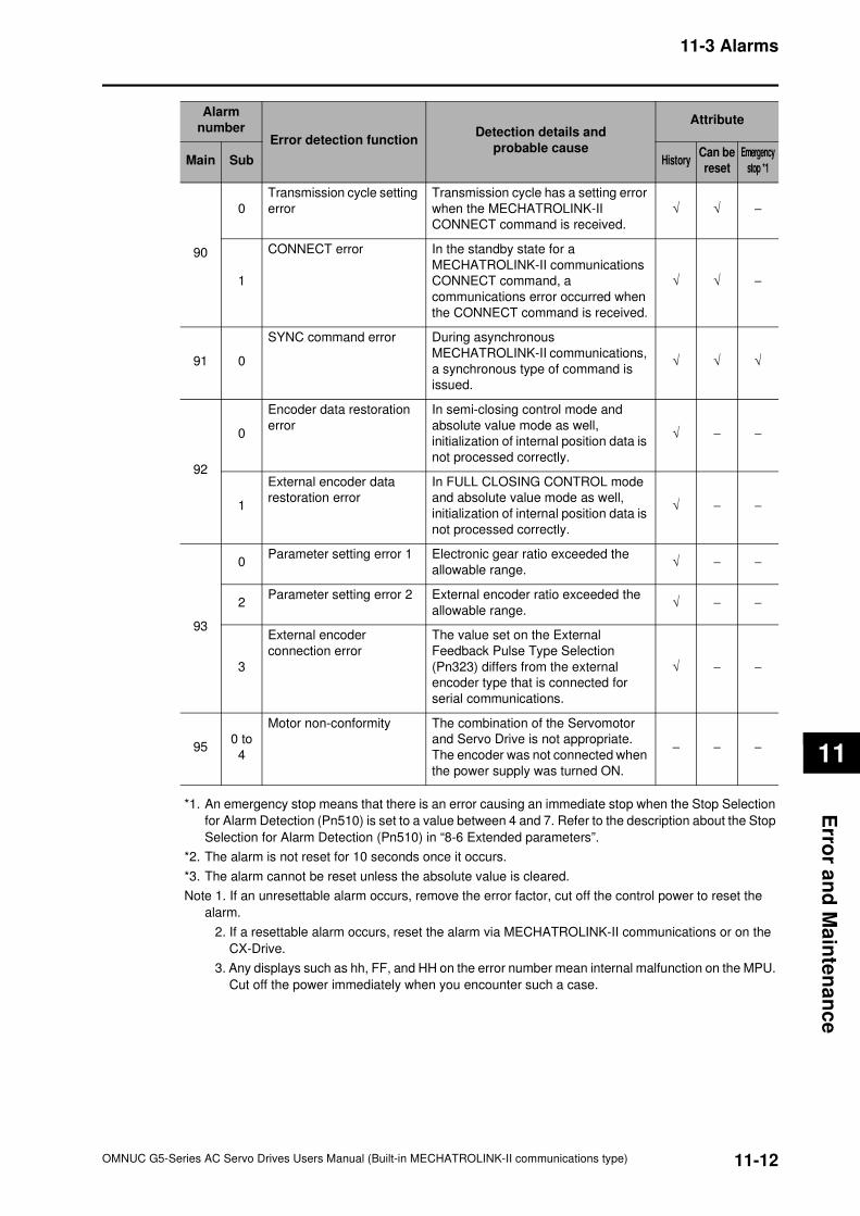
11-12
11-3 Alarms
OMNUC G5-Series AC Servo Drives Users Manual (Built-in MECHATROLINK-II communications type)
11
Erro
r an
d M
ain
ten
an
ce
*1. An emergency stop means that there is an error causing an immediate stop when the Stop Selection
for Alarm Detection (Pn510) is set to a value between 4 and 7. Refer to the description about the Stop
Selection for Alarm Detection (Pn510) in “8-6 Extended parameters”.
*2. The alarm is not reset for 10 seconds once it occurs.
*3. The alarm cannot be reset unless the absolute value is cleared.
Note 1. If an unresettable alarm occurs, remove the error factor, cut off the control power to reset the
alarm.
2. If a resettable alarm occurs, reset the alarm via MECHATROLINK-II communications or on the
CX-Drive.
3. Any displays such as hh, FF, and HH on the error number mean internal malfunction on the MPU.
Cut off the power immediately when you encounter such a case.
90
0
Transmission cycle setting
error
Transmission cycle has a setting error
when the MECHATROLINK-II
CONNECT command is received.
√ √ −
1
CONNECT error In the standby state for a
MECHATROLINK-II communications
CONNECT command, a
communications error occurred when
the CONNECT command is received.
√ √ −
91 0
SYNC command error During asynchronous
MECHATROLINK-II communications,
a synchronous type of command is
issued.
√ √ √
92
0
Encoder data restoration
error
In semi-closing control mode and
absolute value mode as well,
initialization of internal position data is
not processed correctly.
√ − −
1
External encoder data
restoration error
In FULL CLOSING CONTROL mode
and absolute value mode as well,
initialization of internal position data is
not processed correctly.
√ − −
93
0Parameter setting error 1 Electronic gear ratio exceeded the
allowable range.√ − −
2Parameter setting error 2 External encoder ratio exceeded the
allowable range.√ − −
3
External encoder
connection error
The value set on the External
Feedback Pulse Type Selection
(Pn323) differs from the external
encoder type that is connected for
serial communications.
√ − −
950 to
4
Motor non-conformity The combination of the Servomotor
and Servo Drive is not appropriate.
The encoder was not connected when
the power supply was turned ON.
− − −
Alarm
numberError detection function
Detection details and
probable cause
Attribute
Main Sub HistoryCan be
reset
Emergency
stop *1
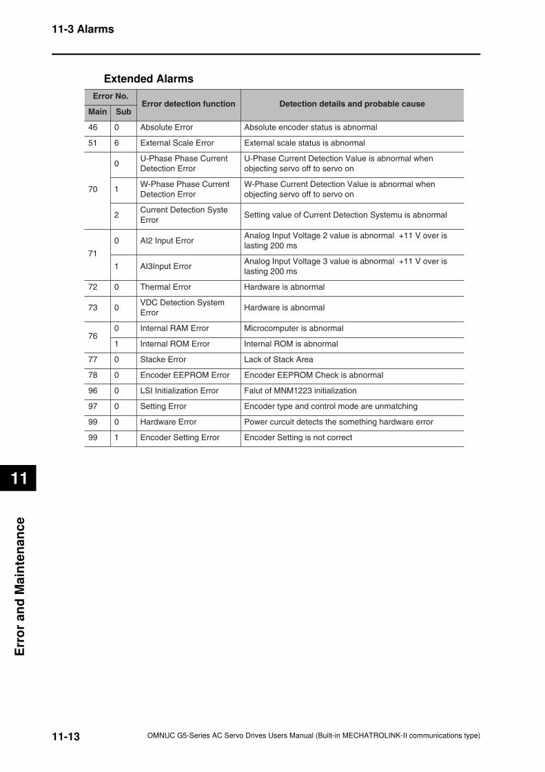
11-13
11-3 Alarms
OMNUC G5-Series AC Servo Drives Users Manual (Built-in MECHATROLINK-II communications type)
11
Err
or
an
d M
ain
ten
an
ce
Extended Alarms
Error No.
Error detection function Detection details and probable cause
Main Sub
46 0 Absolute Error Absolute encoder status is abnormal
51 6 External Scale Error External scale status is abnormal
70
0U-Phase Phase Current
Detection Error
U-Phase Current Detection Value is abnormal when
objecting servo off to servo on
1W-Phase Phase Current
Detection Error
W-Phase Current Detection Value is abnormal when
objecting servo off to servo on
2Current Detection Syste
ErrorSetting value of Current Detection Systemu is abnormal
71
0 AI2 Input ErrorAnalog Input Voltage 2 value is abnormal +11 V over is
lasting 200 ms
1 AI3Input ErrorAnalog Input Voltage 3 value is abnormal +11 V over is
lasting 200 ms
72 0 Thermal Error Hardware is abnormal
73 0VDC Detection System
ErrorHardware is abnormal
760 Internal RAM Error Microcomputer is abnormal
1 Internal ROM Error Internal ROM is abnormal
77 0 Stacke Error Lack of Stack Area
78 0 Encoder EEPROM Error Encoder EEPROM Check is abnormal
96 0 LSI Initialization Error Falut of MNM1223 initialization
97 0 Setting Error Encoder type and control mode are unmatching
99 0 Hardware Error Power curcuit detects the something hardware error
99 1 Encoder Setting Error Encoder Setting is not correct
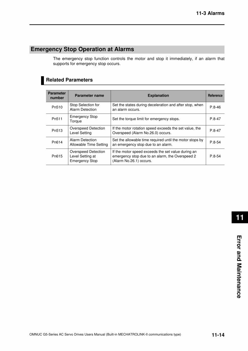
11-14
11-3 Alarms
OMNUC G5-Series AC Servo Drives Users Manual (Built-in MECHATROLINK-II communications type)
11
Erro
r an
d M
ain
ten
an
ce
Emergency Stop Operation at Alarms
The emergency stop function controls the motor and stop it immediately, if an alarm that
supports for emergency stop occurs.
Related Parameters
Parameter
numberParameter name Explanation Reference
Pn510Stop Selection for
Alarm Detection
Set the states during deceleration and after stop, when
an alarm occurs.P.8-46
Pn511Emergency Stop
TorqueSet the torque limit for emergency stops. P.8-47
Pn513Overspeed Detection
Level Setting
If the motor rotation speed exceeds the set value, the
Overspeed (Alarm No.26.0) occurs. P.8-47
Pn614Alarm Detection
Allowable Time Setting
Set the allowable time required until the motor stops by
an emergency stop due to an alarm.P.8-54
Pn615
Overspeed Detection
Level Setting at
Emergency Stop
If the motor speed exceeds the set value during an
emergency stop due to an alarm, the Overspeed 2
(Alarm No.26.1) occurs.
P.8-54
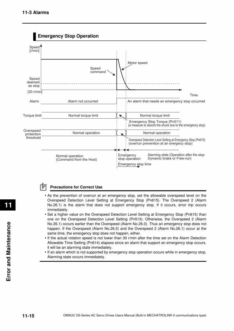
11-15
11-3 Alarms
OMNUC G5-Series AC Servo Drives Users Manual (Built-in MECHATROLINK-II communications type)
11
Err
or
an
d M
ain
ten
an
ce
Emergency Stop Operation
Precautions for Correct Use
As the prevention of overrun at an emergency stop, set the allowable overspeed level on the
Overspeed Detection Level Setting at Emergency Stop (Pn615). The Overspeed 2 (Alarm
No.26.1) is the alarm that does not support emergency stop. If it occurs, error trip occurs
immediately.
Set a higher value on the Overspeed Detection Level Setting at Emergency Stop (Pn615) than
one on the Overspeed Detection Level Setting (Pn513). Otherwise, the Overspeed 2 (Alarm
No.26.1) occurs earlier than the Overspeed (Alarm No.26.0). Thus an emergency stop does not
happen. If the Overspeed (Alarm No.26.0) and the Overspeed 2 (Alarm No.26.1) occur at the
same time, the emergency stop does not happen, either.
If the actual rotation speed is not lower than 30 r/min after the time set on the Alarm Detection
Allowable Time Setting (Pn614) elapses since an alarm that support an emergency stop occurs,
it will be an alarming state immediately.
If an alarm which is not supported by emergency stop operation occurs while in emergency stop,
Alarming state occurs immediately.
Torque limit
Speed [r/min]
Time
Alarming state (Operation after the stop: Dynamic brake or Free-run)
Emergency stop operation
Normal operation (Command from the Host)
Speed command
Motor speed
Normal torque limitNormal torque limit
An alarm that needs an emergency stop occurredAlarm not occurred Alarm
Speeddeemedas stop
[30 r/min]
Emergency stop time
Overspeedprotectionthreshold
Normal operationNormal operation
Overspeed Detection Level Setting at Emergency Stop (Pn615)(overrun prevention at an emergency stop)
Emergency Stop Torque (Pn511) (a measure to absorb the shock due to the emergency stop)
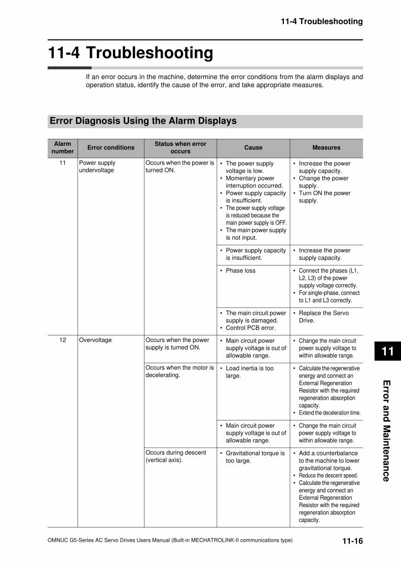
11-16
11-4 Troubleshooting
OMNUC G5-Series AC Servo Drives Users Manual (Built-in MECHATROLINK-II communications type)
11
Erro
r an
d M
ain
ten
an
ce
11-4 Troubleshooting
If an error occurs in the machine, determine the error conditions from the alarm displays and
operation status, identify the cause of the error, and take appropriate measures.
Error Diagnosis Using the Alarm Displays
Alarm
numberError conditions
Status when error
occursCause Measures
11 Power supply
undervoltage
Occurs when the power is
turned ON.• The power supply
voltage is low.
• Momentary power
interruption occurred.
• Power supply capacity
is insufficient.
• The power supply voltage
is reduced because the
main power supply is OFF.
• The main power supply
is not input.
• Increase the power
supply capacity.
• Change the power
supply.
• Turn ON the power
supply.
• Power supply capacity
is insufficient.
• Increase the power
supply capacity.
• Phase loss • Connect the phases (L1,
L2, L3) of the power
supply voltage correctly.
• For single-phase, connect
to L1 and L3 correctly.
• The main circuit power
supply is damaged.
• Control PCB error.
• Replace the Servo
Drive.
12 Overvoltage Occurs when the power
supply is turned ON.• Main circuit power
supply voltage is out of
allowable range.
• Change the main circuit
power supply voltage to
within allowable range.
Occurs when the motor is
decelerating.• Load inertia is too
large.
• Calculate the regenerative
energy and connect an
External Regeneration
Resistor with the required
regeneration absorption
capacity.
• Extend the deceleration time.
• Main circuit power
supply voltage is out of
allowable range.
• Change the main circuit
power supply voltage to
within allowable range.
Occurs during descent
(vertical axis).• Gravitational torque is
too large.
• Add a counterbalance
to the machine to lower
gravitational torque.
• Reduce the descent speed.
• Calculate the regenerative
energy and connect an
External Regeneration
Resistor with the required
regeneration absorption
capacity.
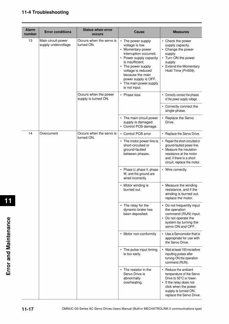
11-17
11-4 Troubleshooting
OMNUC G5-Series AC Servo Drives Users Manual (Built-in MECHATROLINK-II communications type)
11
Err
or
an
d M
ain
ten
an
ce
13 Main circuit power
supply undervoltage
Occurs when the servo is
turned ON.• The power supply
voltage is low.
• Momentary power
interruption occurred.
• Power supply capacity
is insufficient.
• The power supply
voltage is reduced
because the main
power supply is OFF.
• The main power supply
is not input.
• Check the power
supply capacity.
• Change the power
supply.
• Turn ON the power
supply.
• Extend the Momentary
Hold Time (Pn509).
Occurs when the power
supply is turned ON.• Phase loss • Correctly connect the phases
of the power supply voltage.
• Correctly connect the
single-phase.
• The main circuit power
supply is damaged.
• Control PCB damage.
• Replace the Servo
Drive.
14 Overcurrent Occurs when the servo is
turned ON.• Control PCB error • Replace the Servo Drive.
• The motor power line is
short-circuited or
ground-faulted
between phases.
• Repair the short-circuited or
ground-faulted power line.
• Measure the insulation
resistance at the motor
and, if there is a short
circuit, replace the motor.
• Phase U, phase V, phase
W, and the ground are
wired incorrectly.
• Wire correctly.
• Motor winding is
burned out.
• Measure the winding
resistance, and if the
winding is burned out,
replace the motor.
• The relay for the
dynamic brake has
been deposited.
• Do not frequently input
the operation
command (RUN) input.
• Do not operate the
system by turning the
servo ON and OFF.
• Motor non-conformity • Use a Servomotor that is
appropriate for use with
the Servo Drive.
• The pulse input timing
is too early.
• Wait at least 100 ms before
inputting pulses after
turning ON the operation
command (RUN).
• The resistor in the
Servo Drive is
abnormally
overheating.
• Reduce the ambient
temperature of the Servo
Drive to 55°C or lower.
• If the relay does not
click when the power
supply is turned ON,
replace the Servo Drive.
Alarm
numberError conditions
Status when error
occursCause Measures
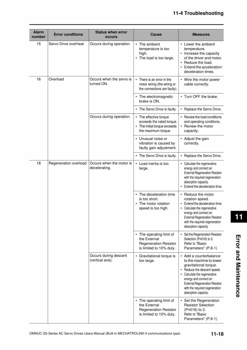
11-18
11-4 Troubleshooting
OMNUC G5-Series AC Servo Drives Users Manual (Built-in MECHATROLINK-II communications type)
11
Erro
r an
d M
ain
ten
an
ce
15 Servo Drive overheat Occurs during operation. • The ambient
temperature is too
high.
• The load is too large.
• Lower the ambient
temperature.
• Increase the capacity
of the driver and motor.
• Reduce the load.
• Extend the acceleration/
deceleration times.
16 Overload Occurs when the servo is
turned ON.• There is an error in the
motor wiring (the wiring or
the connections are faulty).
• Wire the motor power
cable correctly.
• The electromagnetic
brake is ON.
• Turn OFF the brake.
• The Servo Drive is faulty. • Replace the Servo Drive.
Occurs during operation. • The effective torque
exceeds the rated torque.
• The initial torque exceeds
the maximum torque.
• Review the load conditions
and operating conditions.
• Review the motor
capacity.
• Unusual noise or
vibration is caused by
faulty gain adjustment.
• Adjust the gain
correctly.
• The Servo Drive is faulty. • Replace the Servo Drive.
18 Regeneration overload Occurs when the motor is
decelerating.• Load inertia is too
large.
• Calculate the regenerative
energy and connect an
External Regeneration Resistor
with the required regeneration
absorption capacity.
• Extend the deceleration time.
• The deceleration time
is too short.
• The motor rotation
speed is too high.
• Reduce the motor
rotation speed.
• Extend the deceleration time.
• Calculate the regenerative
energy and connect an
External Regeneration Resistor
with the required regeneration
absorption capacity.
• The operating limit of
the External
Regeneration Resistor
is limited to 10% duty.
• Set the Regeneration Resistor
Selection (Pn016) to 2.
Refer to "Basic
Parameters" (P.8-1)
Occurs during descent
(vertical axis).• Gravitational torque is
too large.
• Add a counterbalance
to the machine to lower
gravitational torque.
• Reduce the descent speed.
• Calculate the regenerative
energy and connect an
External Regeneration Resistor
with the required regeneration
absorption capacity.
• The operating limit of
the External
Regeneration Resistor
is limited to 10% duty.
• Set the Regeneration
Resistor Selection
(Pn016) to 2.
Refer to "Basic
Parameters" (P.8-1)
Alarm
numberError conditions
Status when error
occursCause Measures
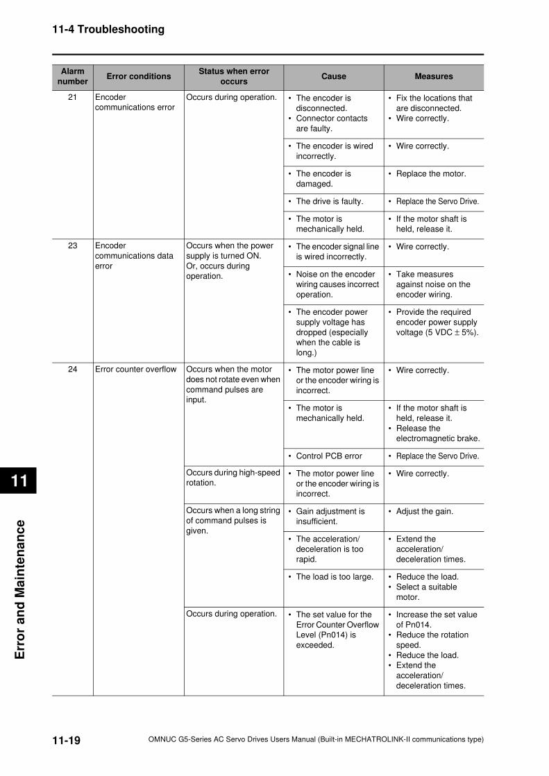
11-19
11-4 Troubleshooting
OMNUC G5-Series AC Servo Drives Users Manual (Built-in MECHATROLINK-II communications type)
11
Err
or
an
d M
ain
ten
an
ce
21 Encoder
communications error
Occurs during operation. • The encoder is
disconnected.
• Connector contacts
are faulty.
• Fix the locations that
are disconnected.
• Wire correctly.
• The encoder is wired
incorrectly.
• Wire correctly.
• The encoder is
damaged.
• Replace the motor.
• The drive is faulty. • Replace the Servo Drive.
• The motor is
mechanically held.
• If the motor shaft is
held, release it.
23 Encoder
communications data
error
Occurs when the power
supply is turned ON.
Or, occurs during
operation.
• The encoder signal line
is wired incorrectly.
• Wire correctly.
• Noise on the encoder
wiring causes incorrect
operation.
• Take measures
against noise on the
encoder wiring.
• The encoder power
supply voltage has
dropped (especially
when the cable is
long.)
• Provide the required
encoder power supply
voltage (5 VDC ± 5%).
24 Error counter overflow Occurs when the motor
does not rotate even when
command pulses are
input.
• The motor power line
or the encoder wiring is
incorrect.
• Wire correctly.
• The motor is
mechanically held.
• If the motor shaft is
held, release it.
• Release the
electromagnetic brake.
• Control PCB error • Replace the Servo Drive.
Occurs during high-speed
rotation.• The motor power line
or the encoder wiring is
incorrect.
• Wire correctly.
Occurs when a long string
of command pulses is
given.
• Gain adjustment is
insufficient.
• Adjust the gain.
• The acceleration/
deceleration is too
rapid.
• Extend the
acceleration/
deceleration times.
• The load is too large. • Reduce the load.
• Select a suitable
motor.
Occurs during operation. • The set value for the
Error Counter Overflow
Level (Pn014) is
exceeded.
• Increase the set value
of Pn014.
• Reduce the rotation
speed.
• Reduce the load.
• Extend the
acceleration/
deceleration times.
Alarm
numberError conditions
Status when error
occursCause Measures
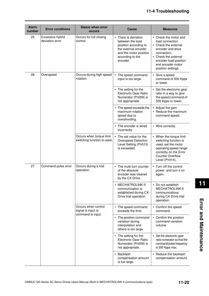
11-20
11-4 Troubleshooting
OMNUC G5-Series AC Servo Drives Users Manual (Built-in MECHATROLINK-II communications type)
11
Erro
r an
d M
ain
ten
an
ce
25 Excessive hybrid
deviation error
Occurs for full closing
control.• There is deviation
between the load
position according to
the external encoder
and the motor position
according to the
encoder.
• Check the motor and
load connection.
• Check the external
encoder and drive
connection.
• Check the external
encoder load position
and encoder motor
position settings.
26 Overspeed Occurs during high-speed
rotation.• The speed command
input is too large.
• Give a speed
command of 500 Kpps
or lower.
• The setting for the
Electronic Gear Ratio
Numerator (Pn009) is
not appropriate.
• Set the electronic gear
ratio in a way to give
the speed command of
500 Kpps or lower.
• The speed exceeds the
maximum rotation
speed due to
overshooting.
• Adjust the gain.
• Reduce the maximum
command speed.
• The encoder is wired
incorrectly.
• Wire correctly.
Occurs when torque limit
switching function is used.• The set value for the
Overspeed Detection
Level Setting (Pn513)
is exceeded.
• When the torque limit
switching function is
used, set the motor
operating speed range
correctly on the Error
Counter Overflow
Level (Pn014).
27 Command pulse error Occurs during a trial
operation.• The multi-turn counter
of the absolute
encoder was cleared
by the CX-Drive.
• Turn off the control
power, and turn it on
again.
• MECHATROLINK-II
communication is
established during CX-
Drive trial operation.
• Do not establish
MECHATROLINK-II
communications
during CX-Drive trial
operation.
Occurs when control
signal is input or
command is input.
• The speed command
exceeds the limit.
• Confirm the speed
command.
• The position command
variation during
interpolation and
others is too large.
• Confirm the position
command variation
volume.
• The setting for the
Electronic Gear Ratio
Numerator (Pn009) is
not appropriate.
• Set the electronic gear
ratio numerator so that the
command pulse frequency
is 500 Kpps max.
• Backlash
compensation amount
is too large.
• Reduce the backlash
compensation amount.
Alarm
numberError conditions
Status when error
occursCause Measures
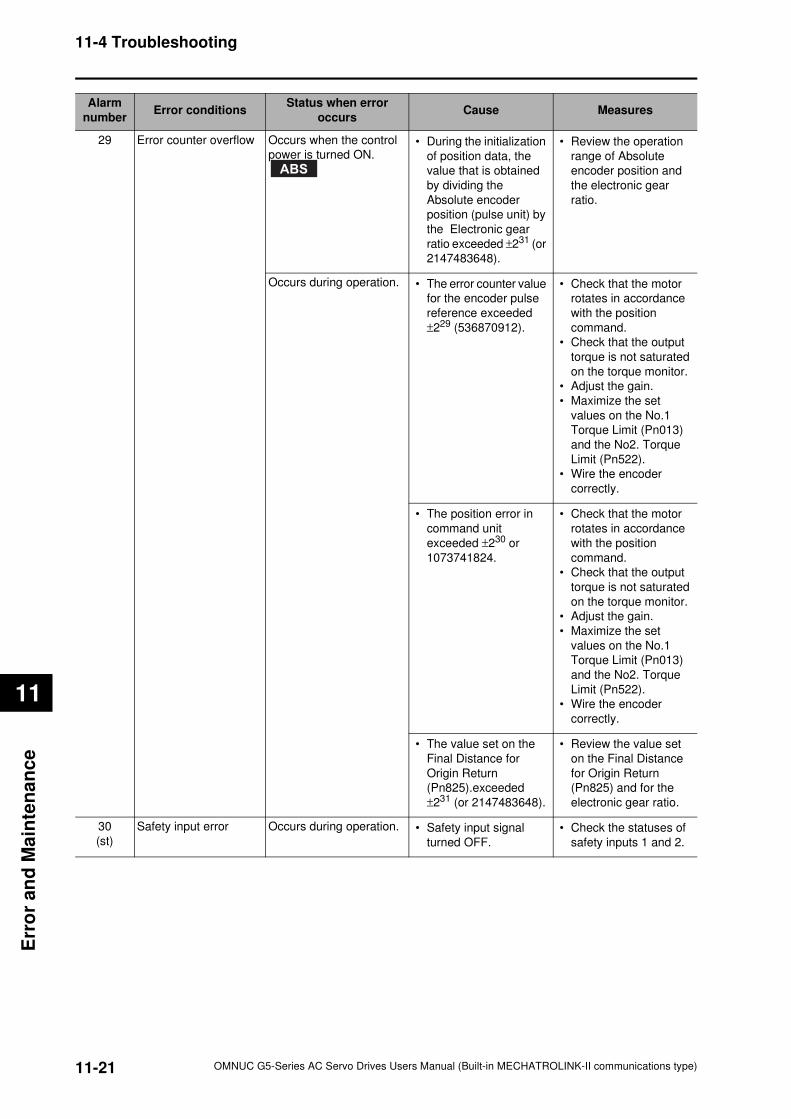
11-21
11-4 Troubleshooting
OMNUC G5-Series AC Servo Drives Users Manual (Built-in MECHATROLINK-II communications type)
11
Err
or
an
d M
ain
ten
an
ce
29 Error counter overflow Occurs when the control
power is turned ON.• During the initialization
of position data, the
value that is obtained
by dividing the
Absolute encoder
position (pulse unit) by
the Electronic gear
ratio exceeded ±231 (or
2147483648).
• Review the operation
range of Absolute
encoder position and
the electronic gear
ratio.
Occurs during operation. • The error counter value
for the encoder pulse
reference exceeded
±229 (536870912).
• Check that the motor
rotates in accordance
with the position
command.
• Check that the output
torque is not saturated
on the torque monitor.
• Adjust the gain.
• Maximize the set
values on the No.1
Torque Limit (Pn013)
and the No2. Torque
Limit (Pn522).
• Wire the encoder
correctly.
• The position error in
command unit
exceeded ±230 or
1073741824.
• Check that the motor
rotates in accordance
with the position
command.
• Check that the output
torque is not saturated
on the torque monitor.
• Adjust the gain.
• Maximize the set
values on the No.1
Torque Limit (Pn013)
and the No2. Torque
Limit (Pn522).
• Wire the encoder
correctly.
• The value set on the
Final Distance for
Origin Return
(Pn825).exceeded
±231 (or 2147483648).
• Review the value set
on the Final Distance
for Origin Return
(Pn825) and for the
electronic gear ratio.
30
(st)
Safety input error Occurs during operation. • Safety input signal
turned OFF.
• Check the statuses of
safety inputs 1 and 2.
Alarm
numberError conditions
Status when error
occursCause Measures
ABS
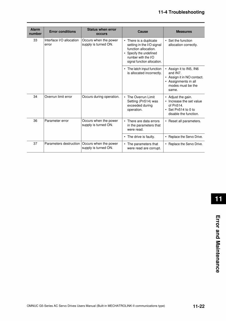
11-22
11-4 Troubleshooting
OMNUC G5-Series AC Servo Drives Users Manual (Built-in MECHATROLINK-II communications type)
11
Erro
r an
d M
ain
ten
an
ce
33 Interface I/O allocation
error
Occurs when the power
supply is turned ON.• There is a duplicate
setting in the I/O signal
function allocation.
• Specify the undefined
number with the I/O
signal function allocation.
• Set the function
allocation correctly.
• The latch input function
is allocated incorrectly.
• Assign it to IN5, IN6
and IN7.
• Assign it in NO contact.
• Assignments in all
modes must be the
same.
34 Overrun limit error Occurs during operation. • The Overrun Limit
Setting (Pn514) was
exceeded during
operation.
• Adjust the gain.
• Increase the set value
of Pn514.
• Set Pn514 to 0 to
disable the function.
36 Parameter error Occurs when the power
supply is turned ON.• There are data errors
in the parameters that
were read.
• Reset all parameters.
• The drive is faulty. • Replace the Servo Drive.
37 Parameters destruction Occurs when the power
supply is turned ON.• The parameters that
were read are corrupt.
• Replace the Servo Drive.
Alarm
numberError conditions
Status when error
occursCause Measures
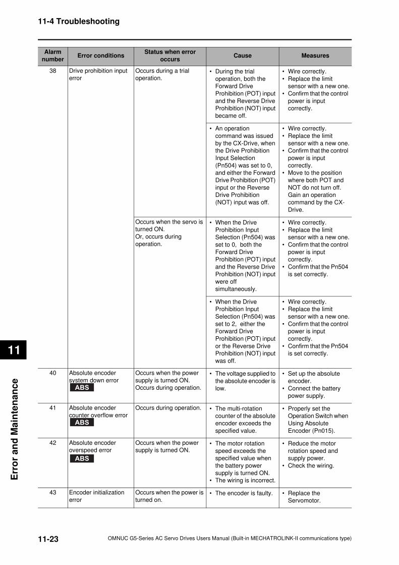
11-23
11-4 Troubleshooting
OMNUC G5-Series AC Servo Drives Users Manual (Built-in MECHATROLINK-II communications type)
11
Err
or
an
d M
ain
ten
an
ce
38 Drive prohibition input
error
Occurs during a trial
operation.• During the trial
operation, both the
Forward Drive
Prohibition (POT) input
and the Reverse Drive
Prohibition (NOT) input
became off.
• Wire correctly.
• Replace the limit
sensor with a new one.
• Confirm that the control
power is input
correctly.
• An operation
command was issued
by the CX-Drive, when
the Drive Prohibition
Input Selection
(Pn504) was set to 0,
and either the Forward
Drive Prohibition (POT)
input or the Reverse
Drive Prohibition
(NOT) input was off.
• Wire correctly.
• Replace the limit
sensor with a new one.
• Confirm that the control
power is input
correctly.
• Move to the position
where both POT and
NOT do not turn off.
Gain an operation
command by the CX-
Drive.
Occurs when the servo is
turned ON.
Or, occurs during
operation.
• When the Drive
Prohibition Input
Selection (Pn504) was
set to 0, both the
Forward Drive
Prohibition (POT) input
and the Reverse Drive
Prohibition (NOT) input
were off
simultaneously.
• Wire correctly.
• Replace the limit
sensor with a new one.
• Confirm that the control
power is input
correctly.
• Confirm that the Pn504
is set correctly.
• When the Drive
Prohibition Input
Selection (Pn504) was
set to 2, either the
Forward Drive
Prohibition (POT) input
or the Reverse Drive
Prohibition (NOT) input
was off.
• Wire correctly.
• Replace the limit
sensor with a new one.
• Confirm that the control
power is input
correctly.
• Confirm that the Pn504
is set correctly.
40 Absolute encoder
system down error
Occurs when the power
supply is turned ON.
Occurs during operation.
• The voltage supplied to
the absolute encoder is
low.
• Set up the absolute
encoder.
• Connect the battery
power supply.
41 Absolute encoder
counter overflow error
Occurs during operation. • The multi-rotation
counter of the absolute
encoder exceeds the
specified value.
• Properly set the
Operation Switch when
Using Absolute
Encoder (Pn015).
42 Absolute encoder
overspeed error
Occurs when the power
supply is turned ON.• The motor rotation
speed exceeds the
specified value when
the battery power
supply is turned ON.
• The wiring is incorrect.
• Reduce the motor
rotation speed and
supply power.
• Check the wiring.
43 Encoder initialization
error
Occurs when the power is
turned on.• The encoder is faulty. • Replace the
Servomotor.
Alarm
numberError conditions
Status when error
occursCause Measures
ABS
ABS
ABS
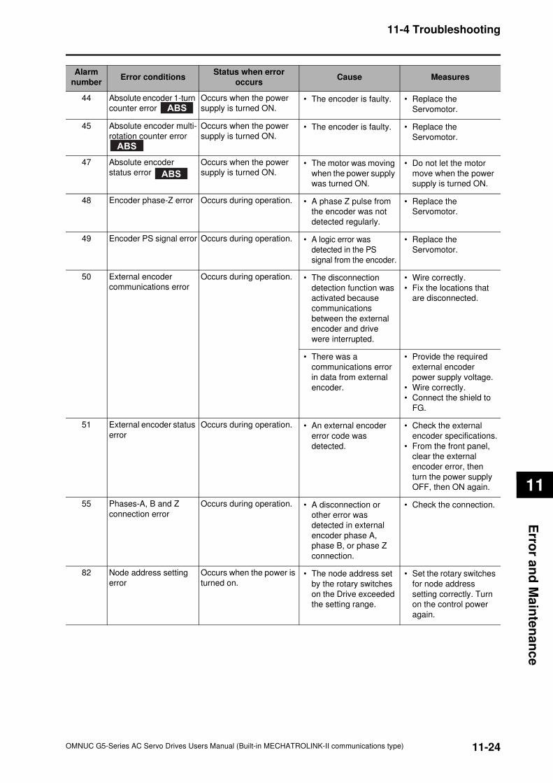
11-24
11-4 Troubleshooting
OMNUC G5-Series AC Servo Drives Users Manual (Built-in MECHATROLINK-II communications type)
11
Erro
r an
d M
ain
ten
an
ce
44 Absolute encoder 1-turn
counter error
Occurs when the power
supply is turned ON.• The encoder is faulty. • Replace the
Servomotor.
45 Absolute encoder multi-
rotation counter error
Occurs when the power
supply is turned ON.• The encoder is faulty. • Replace the
Servomotor.
47 Absolute encoder
status error
Occurs when the power
supply is turned ON.• The motor was moving
when the power supply
was turned ON.
• Do not let the motor
move when the power
supply is turned ON.
48 Encoder phase-Z error Occurs during operation. • A phase Z pulse from
the encoder was not
detected regularly.
• Replace the
Servomotor.
49 Encoder PS signal error Occurs during operation. • A logic error was
detected in the PS
signal from the encoder.
• Replace the
Servomotor.
50 External encoder
communications error
Occurs during operation. • The disconnection
detection function was
activated because
communications
between the external
encoder and drive
were interrupted.
• Wire correctly.
• Fix the locations that
are disconnected.
• There was a
communications error
in data from external
encoder.
• Provide the required
external encoder
power supply voltage.
• Wire correctly.
• Connect the shield to
FG.
51 External encoder status
error
Occurs during operation. • An external encoder
error code was
detected.
• Check the external
encoder specifications.
• From the front panel,
clear the external
encoder error, then
turn the power supply
OFF, then ON again.
55 Phases-A, B and Z
connection error
Occurs during operation. • A disconnection or
other error was
detected in external
encoder phase A,
phase B, or phase Z
connection.
• Check the connection.
82 Node address setting
error
Occurs when the power is
turned on.• The node address set
by the rotary switches
on the Drive exceeded
the setting range.
• Set the rotary switches
for node address
setting correctly. Turn
on the control power
again.
Alarm
numberError conditions
Status when error
occursCause Measures
ABS
ABS
ABS
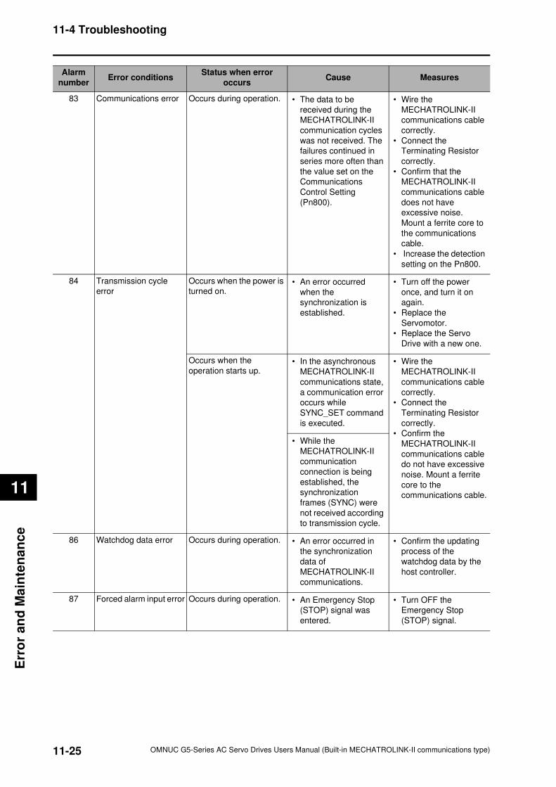
11-25
11-4 Troubleshooting
OMNUC G5-Series AC Servo Drives Users Manual (Built-in MECHATROLINK-II communications type)
11
Err
or
an
d M
ain
ten
an
ce
83 Communications error Occurs during operation. • The data to be
received during the
MECHATROLINK-II
communication cycles
was not received. The
failures continued in
series more often than
the value set on the
Communications
Control Setting
(Pn800).
• Wire the
MECHATROLINK-II
communications cable
correctly.
• Connect the
Terminating Resistor
correctly.
• Confirm that the
MECHATROLINK-II
communications cable
does not have
excessive noise.
Mount a ferrite core to
the communications
cable.
• Increase the detection
setting on the Pn800.
84 Transmission cycle
error
Occurs when the power is
turned on.• An error occurred
when the
synchronization is
established.
• Turn off the power
once, and turn it on
again.
• Replace the
Servomotor.
• Replace the Servo
Drive with a new one.
Occurs when the
operation starts up.• In the asynchronous
MECHATROLINK-II
communications state,
a communication error
occurs while
SYNC_SET command
is executed.
• Wire the
MECHATROLINK-II
communications cable
correctly.
• Connect the
Terminating Resistor
correctly.
• Confirm the
MECHATROLINK-II
communications cable
do not have excessive
noise. Mount a ferrite
core to the
communications cable.
• While the
MECHATROLINK-II
communication
connection is being
established, the
synchronization
frames (SYNC) were
not received according
to transmission cycle.
86 Watchdog data error Occurs during operation. • An error occurred in
the synchronization
data of
MECHATROLINK-II
communications.
• Confirm the updating
process of the
watchdog data by the
host controller.
87 Forced alarm input error Occurs during operation. • An Emergency Stop
(STOP) signal was
entered.
• Turn OFF the
Emergency Stop
(STOP) signal.
Alarm
numberError conditions
Status when error
occursCause Measures
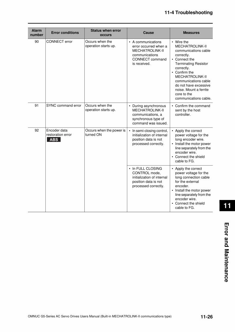
11-26
11-4 Troubleshooting
OMNUC G5-Series AC Servo Drives Users Manual (Built-in MECHATROLINK-II communications type)
11
Erro
r an
d M
ain
ten
an
ce
90 CONNECT error Occurs when the
operation starts up.• A communications
error occurred when a
MECHATROLINK-II
communications
CONNECT command
is received.
• Wire the
MECHATROLINK-II
communications cable
correctly.
• Connect the
Terminating Resistor
correctly.
• Confirm the
MECHATROLINK-II
communications cable
do not have excessive
noise. Mount a ferrite
core to the
communications cable.
91 SYNC command error Occurs when the
operation starts up.• During asynchronous
MECHATROLINK-II
communications, a
synchronous type of
command was issued.
• Confirm the command
sent by the host
controller.
92 Encoder data
restoration error
Occurs when the power is
turned ON• In semi-closing control,
initialization of internal
position data is not
processed correctly.
• Apply the correct
power voltage for the
long encoder wire.
• Install the motor power
line separately from the
encoder wire.
• Connect the shield
cable to FG.
• In FULL CLOSING
CONTROL mode,
initialization of internal
position data is not
processed correctly.
• Apply the correct
power voltage for the
long connection cable
for the external
encoder.
• Install the motor power
line separately from the
encoder wire.
• Connect the shield
cable to FG.
Alarm
numberError conditions
Status when error
occursCause Measures
ABS
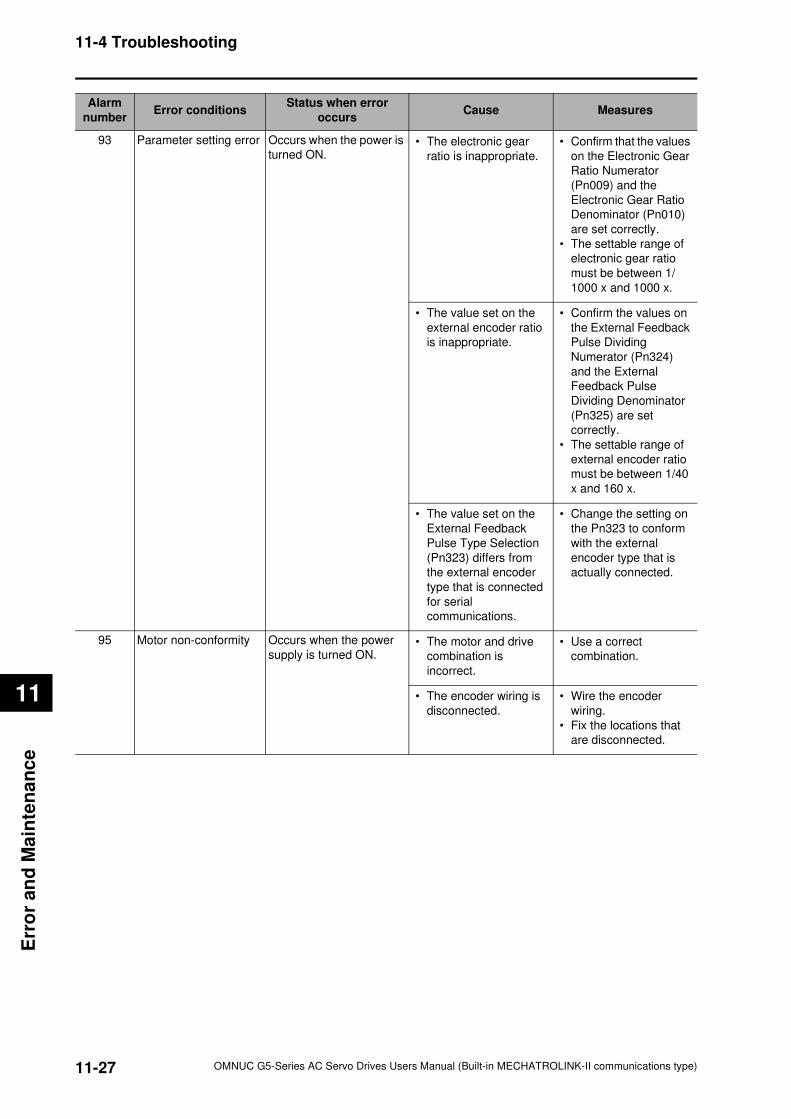
11-27
11-4 Troubleshooting
OMNUC G5-Series AC Servo Drives Users Manual (Built-in MECHATROLINK-II communications type)
11
Err
or
an
d M
ain
ten
an
ce
93 Parameter setting error Occurs when the power is
turned ON.• The electronic gear
ratio is inappropriate.
• Confirm that the values
on the Electronic Gear
Ratio Numerator
(Pn009) and the
Electronic Gear Ratio
Denominator (Pn010)
are set correctly.
• The settable range of
electronic gear ratio
must be between 1/
1000 x and 1000 x.
• The value set on the
external encoder ratio
is inappropriate.
• Confirm the values on
the External Feedback
Pulse Dividing
Numerator (Pn324)
and the External
Feedback Pulse
Dividing Denominator
(Pn325) are set
correctly.
• The settable range of
external encoder ratio
must be between 1/40
x and 160 x.
• The value set on the
External Feedback
Pulse Type Selection
(Pn323) differs from
the external encoder
type that is connected
for serial
communications.
• Change the setting on
the Pn323 to conform
with the external
encoder type that is
actually connected.
95 Motor non-conformity Occurs when the power
supply is turned ON.• The motor and drive
combination is
incorrect.
• Use a correct
combination.
• The encoder wiring is
disconnected.
• Wire the encoder
wiring.
• Fix the locations that
are disconnected.
Alarm
numberError conditions
Status when error
occursCause Measures

11-28
11-4 Troubleshooting
OMNUC G5-Series AC Servo Drives Users Manual (Built-in MECHATROLINK-II communications type)
11
Erro
r an
d M
ain
ten
an
ce
Error Diagnosis Using the Operation Status
Symptom Probable cause Items to check Measures
The 7-segment LED
indicator does not light.
The control power is not
supplied.
Check whether the power
supply input is within the
allowed power supply voltage
range.
Supply the correct power
supply voltage.
Check whether the power
supply input is wired correctly.
Wire correctly.
The LED (COM) is unlit. The MECHATROLINK-II
communications is not
established.
Check that the
communications cable is
connected correctly.
Check that the host
controller has started up.
Check that the Terminating
Resistor is connected
correctly.
Check the connector and
its connection.
The LED (COM) flashes
in green.
Asynchronous
MECHATROLINK-II
communications is
established.
Controllable by the host
controller. (normal state)
Normal state
The LED (COM) lights in
green.
Synchronous
MECHATROLINK-II
communications is
established.
Controllable (normal state) Normal state
The LED (COM) flashes
in red.
A recoverable alarm occurs
in MECHATROLINK-II
communications.
• Reset the network by the
host controller, and
establish the
communications again.
• Check that the
communications cable has
no error.
Check the wiring and
noise condition.
The LED (COM) lights in
red.
An unresettable alarm
occurs in MECHATROLINK-
II communications.
Check that no node address
duplication occurs on the
network, and that the number
of connected nodes is not over
the specification.
Correct the network
address.
An alarm occurs. Read the Error No. and the
alarm log.
Check the cause listed in Error
Diagnosis Using the Alarm
Display in previous pages.
Take appropriate
measures against the
cause of the alarm that
are listed in Error
Diagnosis Using the
Alarm Display in previous
pages.
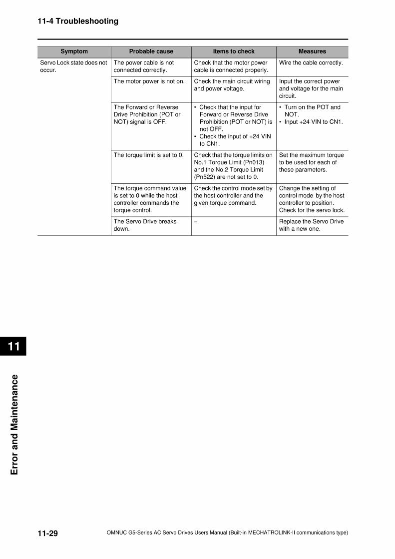
11-29
11-4 Troubleshooting
OMNUC G5-Series AC Servo Drives Users Manual (Built-in MECHATROLINK-II communications type)
11
Err
or
an
d M
ain
ten
an
ce
Servo Lock state does not
occur.
The power cable is not
connected correctly.
Check that the motor power
cable is connected properly.
Wire the cable correctly.
The motor power is not on. Check the main circuit wiring
and power voltage.
Input the correct power
and voltage for the main
circuit.
The Forward or Reverse
Drive Prohibition (POT or
NOT) signal is OFF.
• Check that the input for
Forward or Reverse Drive
Prohibition (POT or NOT) is
not OFF.
• Check the input of +24 VIN
to CN1.
• Turn on the POT and
NOT.
• Input +24 VIN to CN1.
The torque limit is set to 0. Check that the torque limits on
No.1 Torque Limit (Pn013)
and the No.2 Torque Limit
(Pn522) are not set to 0.
Set the maximum torque
to be used for each of
these parameters.
The torque command value
is set to 0 while the host
controller commands the
torque control.
Check the control mode set by
the host controller and the
given torque command.
Change the setting of
control mode by the host
controller to position.
Check for the servo lock.
The Servo Drive breaks
down.
− Replace the Servo Drive
with a new one.
Symptom Probable cause Items to check Measures
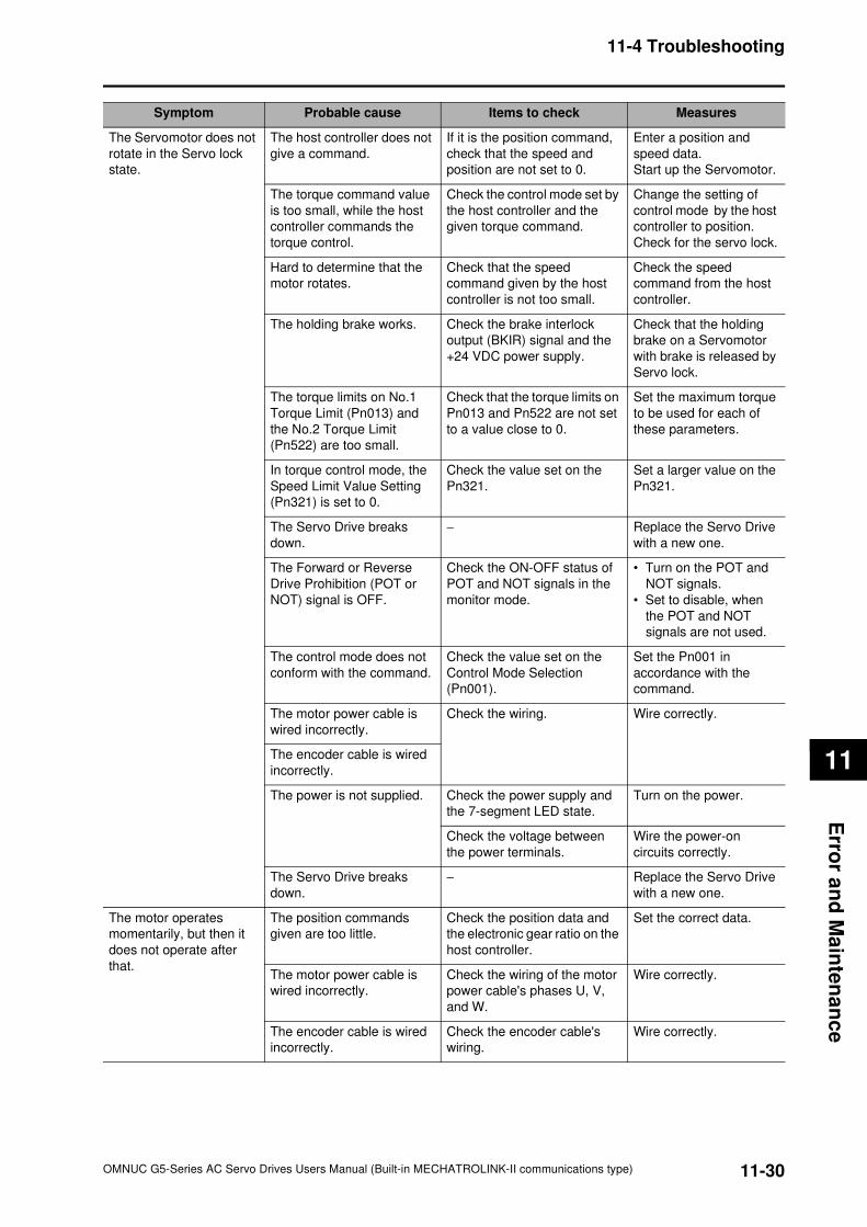
11-30
11-4 Troubleshooting
OMNUC G5-Series AC Servo Drives Users Manual (Built-in MECHATROLINK-II communications type)
11
Erro
r an
d M
ain
ten
an
ce
The Servomotor does not
rotate in the Servo lock
state.
The host controller does not
give a command.
If it is the position command,
check that the speed and
position are not set to 0.
Enter a position and
speed data.
Start up the Servomotor.
The torque command value
is too small, while the host
controller commands the
torque control.
Check the control mode set by
the host controller and the
given torque command.
Change the setting of
control mode by the host
controller to position.
Check for the servo lock.
Hard to determine that the
motor rotates.
Check that the speed
command given by the host
controller is not too small.
Check the speed
command from the host
controller.
The holding brake works. Check the brake interlock
output (BKIR) signal and the
+24 VDC power supply.
Check that the holding
brake on a Servomotor
with brake is released by
Servo lock.
The torque limits on No.1
Torque Limit (Pn013) and
the No.2 Torque Limit
(Pn522) are too small.
Check that the torque limits on
Pn013 and Pn522 are not set
to a value close to 0.
Set the maximum torque
to be used for each of
these parameters.
In torque control mode, the
Speed Limit Value Setting
(Pn321) is set to 0.
Check the value set on the
Pn321.
Set a larger value on the
Pn321.
The Servo Drive breaks
down.
− Replace the Servo Drive
with a new one.
The Forward or Reverse
Drive Prohibition (POT or
NOT) signal is OFF.
Check the ON-OFF status of
POT and NOT signals in the
monitor mode.
• Turn on the POT and
NOT signals.
• Set to disable, when
the POT and NOT
signals are not used.
The control mode does not
conform with the command.
Check the value set on the
Control Mode Selection
(Pn001).
Set the Pn001 in
accordance with the
command.
The motor power cable is
wired incorrectly.
Check the wiring. Wire correctly.
The encoder cable is wired
incorrectly.
The power is not supplied. Check the power supply and
the 7-segment LED state.
Turn on the power.
Check the voltage between
the power terminals.
Wire the power-on
circuits correctly.
The Servo Drive breaks
down.
− Replace the Servo Drive
with a new one.
The motor operates
momentarily, but then it
does not operate after
that.
The position commands
given are too little.
Check the position data and
the electronic gear ratio on the
host controller.
Set the correct data.
The motor power cable is
wired incorrectly.
Check the wiring of the motor
power cable's phases U, V,
and W.
Wire correctly.
The encoder cable is wired
incorrectly.
Check the encoder cable's
wiring.
Wire correctly.
Symptom Probable cause Items to check Measures
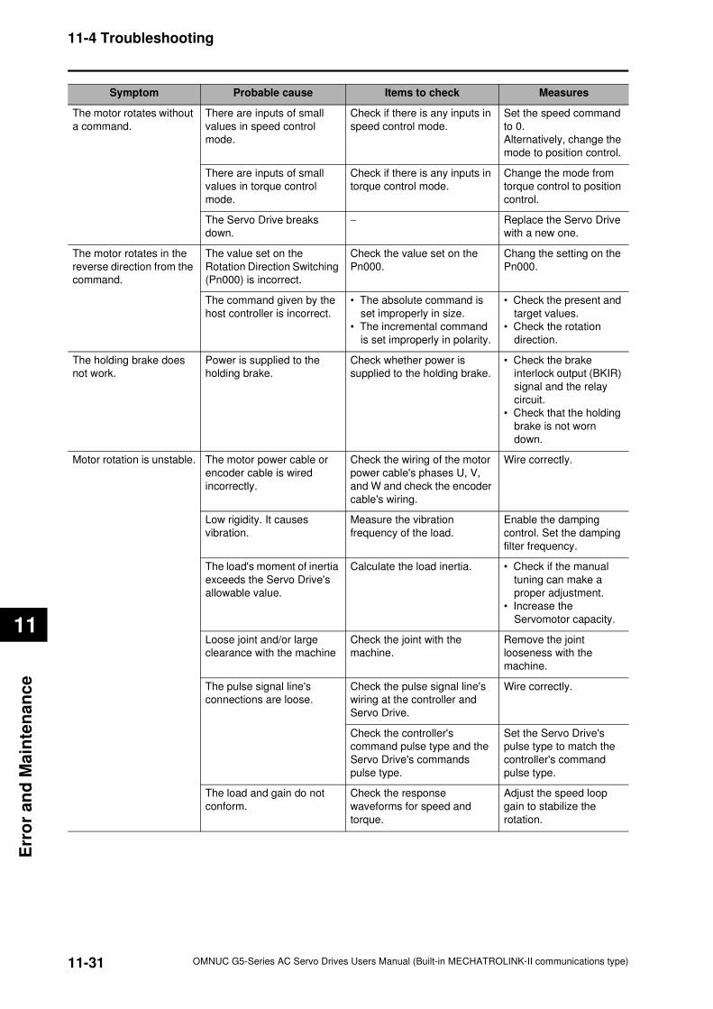
11-31
11-4 Troubleshooting
OMNUC G5-Series AC Servo Drives Users Manual (Built-in MECHATROLINK-II communications type)
11
Err
or
an
d M
ain
ten
an
ce
The motor rotates without
a command.
There are inputs of small
values in speed control
mode.
Check if there is any inputs in
speed control mode.
Set the speed command
to 0.
Alternatively, change the
mode to position control.
There are inputs of small
values in torque control
mode.
Check if there is any inputs in
torque control mode.
Change the mode from
torque control to position
control.
The Servo Drive breaks
down.
− Replace the Servo Drive
with a new one.
The motor rotates in the
reverse direction from the
command.
The value set on the
Rotation Direction Switching
(Pn000) is incorrect.
Check the value set on the
Pn000.
Chang the setting on the
Pn000.
The command given by the
host controller is incorrect.
• The absolute command is
set improperly in size.
• The incremental command
is set improperly in polarity.
• Check the present and
target values.
• Check the rotation
direction.
The holding brake does
not work.
Power is supplied to the
holding brake.
Check whether power is
supplied to the holding brake.
• Check the brake
interlock output (BKIR)
signal and the relay
circuit.
• Check that the holding
brake is not worn
down.
Motor rotation is unstable. The motor power cable or
encoder cable is wired
incorrectly.
Check the wiring of the motor
power cable's phases U, V,
and W and check the encoder
cable's wiring.
Wire correctly.
Low rigidity. It causes
vibration.
Measure the vibration
frequency of the load.
Enable the damping
control. Set the damping
filter frequency.
The load's moment of inertia
exceeds the Servo Drive's
allowable value.
Calculate the load inertia. • Check if the manual
tuning can make a
proper adjustment.
• Increase the
Servomotor capacity.
Loose joint and/or large
clearance with the machine
Check the joint with the
machine.
Remove the joint
looseness with the
machine.
The pulse signal line's
connections are loose.
Check the pulse signal line's
wiring at the controller and
Servo Drive.
Wire correctly.
Check the controller's
command pulse type and the
Servo Drive's commands
pulse type.
Set the Servo Drive's
pulse type to match the
controller's command
pulse type.
The load and gain do not
conform.
Check the response
waveforms for speed and
torque.
Adjust the speed loop
gain to stabilize the
rotation.
Symptom Probable cause Items to check Measures
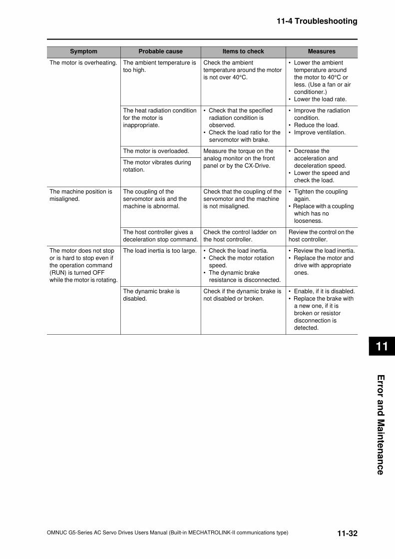
11-32
11-4 Troubleshooting
OMNUC G5-Series AC Servo Drives Users Manual (Built-in MECHATROLINK-II communications type)
11
Erro
r an
d M
ain
ten
an
ce
The motor is overheating. The ambient temperature is
too high.
Check the ambient
temperature around the motor
is not over 40°C.
• Lower the ambient
temperature around
the motor to 40°C or
less. (Use a fan or air
conditioner.)
• Lower the load rate.
The heat radiation condition
for the motor is
inappropriate.
• Check that the specified
radiation condition is
observed.
• Check the load ratio for the
servomotor with brake.
• Improve the radiation
condition.
• Reduce the load.
• Improve ventilation.
The motor is overloaded. Measure the torque on the
analog monitor on the front
panel or by the CX-Drive.
• Decrease the
acceleration and
deceleration speed.
• Lower the speed and
check the load.
The motor vibrates during
rotation.
The machine position is
misaligned.
The coupling of the
servomotor axis and the
machine is abnormal.
Check that the coupling of the
servomotor and the machine
is not misaligned.
• Tighten the coupling
again.
• Replace with a coupling
which has no
looseness.
The host controller gives a
deceleration stop command.
Check the control ladder on
the host controller.
Review the control on the
host controller.
The motor does not stop
or is hard to stop even if
the operation command
(RUN) is turned OFF
while the motor is rotating.
The load inertia is too large. • Check the load inertia.
• Check the motor rotation
speed.
• The dynamic brake
resistance is disconnected.
• Review the load inertia.
• Replace the motor and
drive with appropriate
ones.
The dynamic brake is
disabled.
Check if the dynamic brake is
not disabled or broken.
• Enable, if it is disabled.
• Replace the brake with
a new one, if it is
broken or resistor
disconnection is
detected.
Symptom Probable cause Items to check Measures
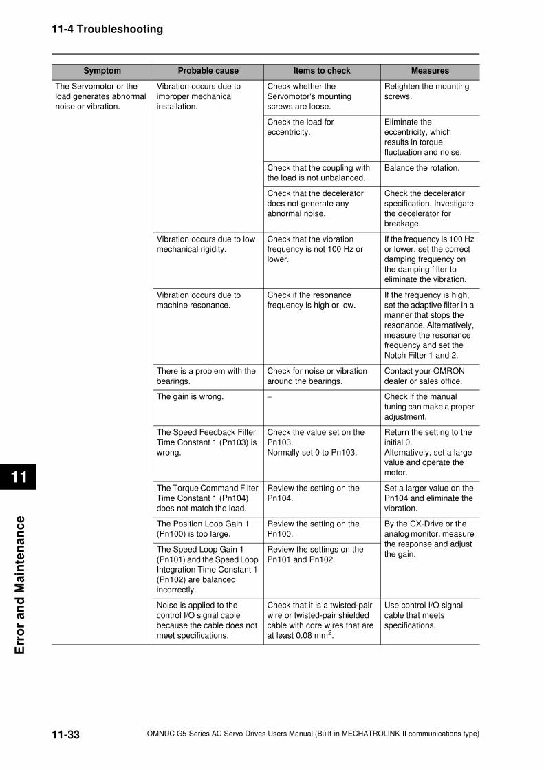
11-33
11-4 Troubleshooting
OMNUC G5-Series AC Servo Drives Users Manual (Built-in MECHATROLINK-II communications type)
11
Err
or
an
d M
ain
ten
an
ce
The Servomotor or the
load generates abnormal
noise or vibration.
Vibration occurs due to
improper mechanical
installation.
Check whether the
Servomotor's mounting
screws are loose.
Retighten the mounting
screws.
Check the load for
eccentricity.
Eliminate the
eccentricity, which
results in torque
fluctuation and noise.
Check that the coupling with
the load is not unbalanced.
Balance the rotation.
Check that the decelerator
does not generate any
abnormal noise.
Check the decelerator
specification. Investigate
the decelerator for
breakage.
Vibration occurs due to low
mechanical rigidity.
Check that the vibration
frequency is not 100 Hz or
lower.
If the frequency is 100 Hz
or lower, set the correct
damping frequency on
the damping filter to
eliminate the vibration.
Vibration occurs due to
machine resonance.
Check if the resonance
frequency is high or low.
If the frequency is high,
set the adaptive filter in a
manner that stops the
resonance. Alternatively,
measure the resonance
frequency and set the
Notch Filter 1 and 2.
There is a problem with the
bearings.
Check for noise or vibration
around the bearings.
Contact your OMRON
dealer or sales office.
The gain is wrong. − Check if the manual
tuning can make a proper
adjustment.
The Speed Feedback Filter
Time Constant 1 (Pn103) is
wrong.
Check the value set on the
Pn103.
Normally set 0 to Pn103.
Return the setting to the
initial 0.
Alternatively, set a large
value and operate the
motor.
The Torque Command Filter
Time Constant 1 (Pn104)
does not match the load.
Review the setting on the
Pn104.
Set a larger value on the
Pn104 and eliminate the
vibration.
The Position Loop Gain 1
(Pn100) is too large.
Review the setting on the
Pn100.
By the CX-Drive or the
analog monitor, measure
the response and adjust
the gain.The Speed Loop Gain 1
(Pn101) and the Speed Loop
Integration Time Constant 1
(Pn102) are balanced
incorrectly.
Review the settings on the
Pn101 and Pn102.
Noise is applied to the
control I/O signal cable
because the cable does not
meet specifications.
Check that it is a twisted-pair
wire or twisted-pair shielded
cable with core wires that are
at least 0.08 mm2.
Use control I/O signal
cable that meets
specifications.
Symptom Probable cause Items to check Measures
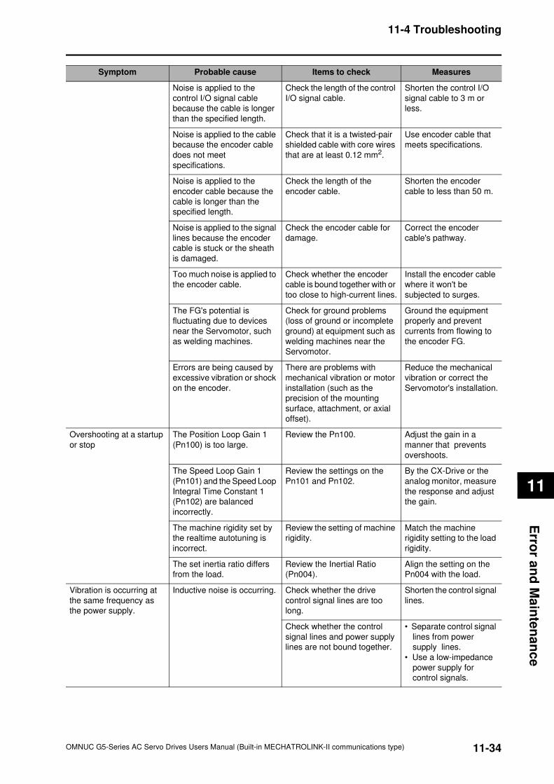
11-34
11-4 Troubleshooting
OMNUC G5-Series AC Servo Drives Users Manual (Built-in MECHATROLINK-II communications type)
11
Erro
r an
d M
ain
ten
an
ce
Noise is applied to the
control I/O signal cable
because the cable is longer
than the specified length.
Check the length of the control
I/O signal cable.
Shorten the control I/O
signal cable to 3 m or
less.
Noise is applied to the cable
because the encoder cable
does not meet
specifications.
Check that it is a twisted-pair
shielded cable with core wires
that are at least 0.12 mm2.
Use encoder cable that
meets specifications.
Noise is applied to the
encoder cable because the
cable is longer than the
specified length.
Check the length of the
encoder cable.
Shorten the encoder
cable to less than 50 m.
Noise is applied to the signal
lines because the encoder
cable is stuck or the sheath
is damaged.
Check the encoder cable for
damage.
Correct the encoder
cable's pathway.
Too much noise is applied to
the encoder cable.
Check whether the encoder
cable is bound together with or
too close to high-current lines.
Install the encoder cable
where it won't be
subjected to surges.
The FG's potential is
fluctuating due to devices
near the Servomotor, such
as welding machines.
Check for ground problems
(loss of ground or incomplete
ground) at equipment such as
welding machines near the
Servomotor.
Ground the equipment
properly and prevent
currents from flowing to
the encoder FG.
Errors are being caused by
excessive vibration or shock
on the encoder.
There are problems with
mechanical vibration or motor
installation (such as the
precision of the mounting
surface, attachment, or axial
offset).
Reduce the mechanical
vibration or correct the
Servomotor's installation.
Overshooting at a startup
or stop
The Position Loop Gain 1
(Pn100) is too large.
Review the Pn100. Adjust the gain in a
manner that prevents
overshoots.
The Speed Loop Gain 1
(Pn101) and the Speed Loop
Integral Time Constant 1
(Pn102) are balanced
incorrectly.
Review the settings on the
Pn101 and Pn102.
By the CX-Drive or the
analog monitor, measure
the response and adjust
the gain.
The machine rigidity set by
the realtime autotuning is
incorrect.
Review the setting of machine
rigidity.
Match the machine
rigidity setting to the load
rigidity.
The set inertia ratio differs
from the load.
Review the Inertial Ratio
(Pn004).
Align the setting on the
Pn004 with the load.
Vibration is occurring at
the same frequency as
the power supply.
Inductive noise is occurring. Check whether the drive
control signal lines are too
long.
Shorten the control signal
lines.
Check whether the control
signal lines and power supply
lines are not bound together.
• Separate control signal
lines from power
supply lines.
• Use a low-impedance
power supply for
control signals.
Symptom Probable cause Items to check Measures
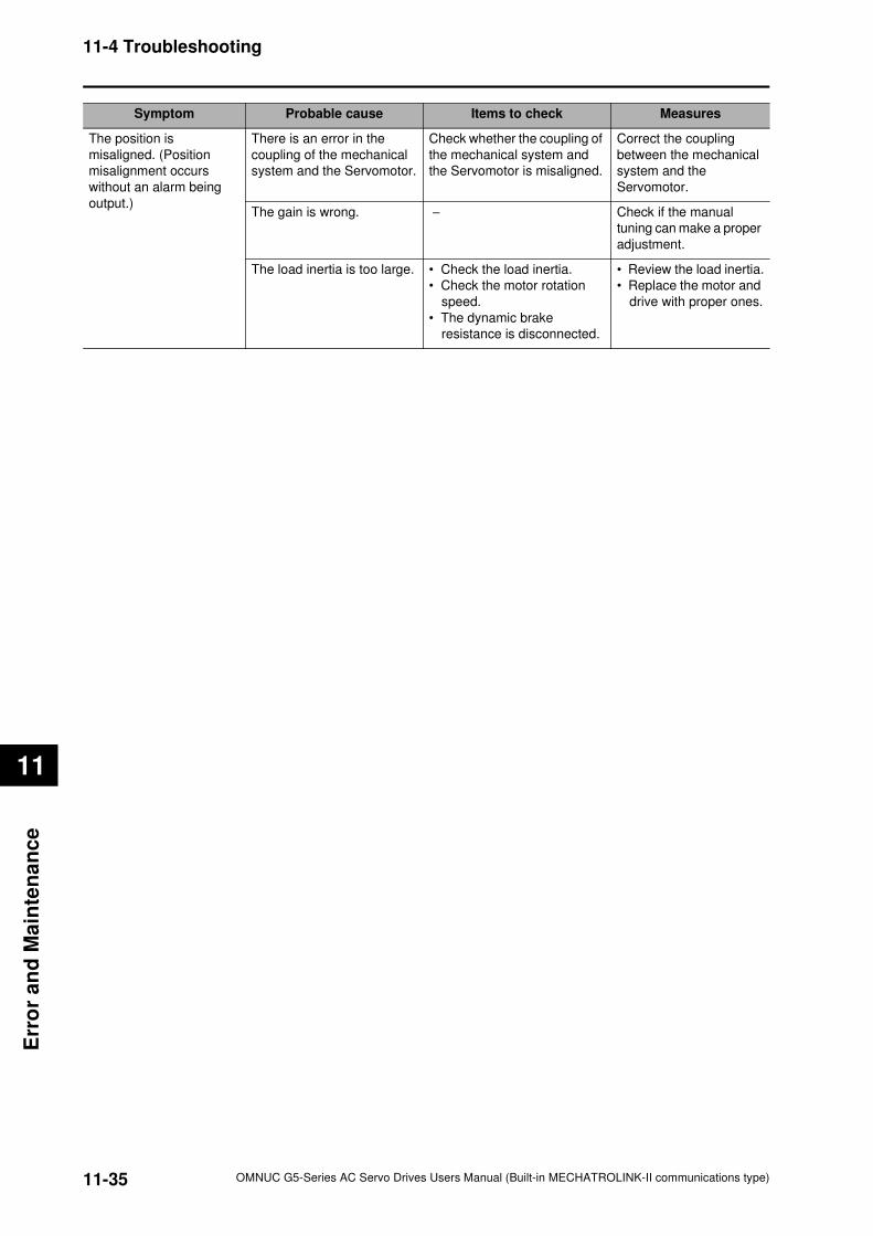
11-35
11-4 Troubleshooting
OMNUC G5-Series AC Servo Drives Users Manual (Built-in MECHATROLINK-II communications type)
11
Err
or
an
d M
ain
ten
an
ce
The position is
misaligned. (Position
misalignment occurs
without an alarm being
output.)
There is an error in the
coupling of the mechanical
system and the Servomotor.
Check whether the coupling of
the mechanical system and
the Servomotor is misaligned.
Correct the coupling
between the mechanical
system and the
Servomotor.
The gain is wrong. − Check if the manual
tuning can make a proper
adjustment.
The load inertia is too large. • Check the load inertia.
• Check the motor rotation
speed.
• The dynamic brake
resistance is disconnected.
• Review the load inertia.
• Replace the motor and
drive with proper ones.
Symptom Probable cause Items to check Measures
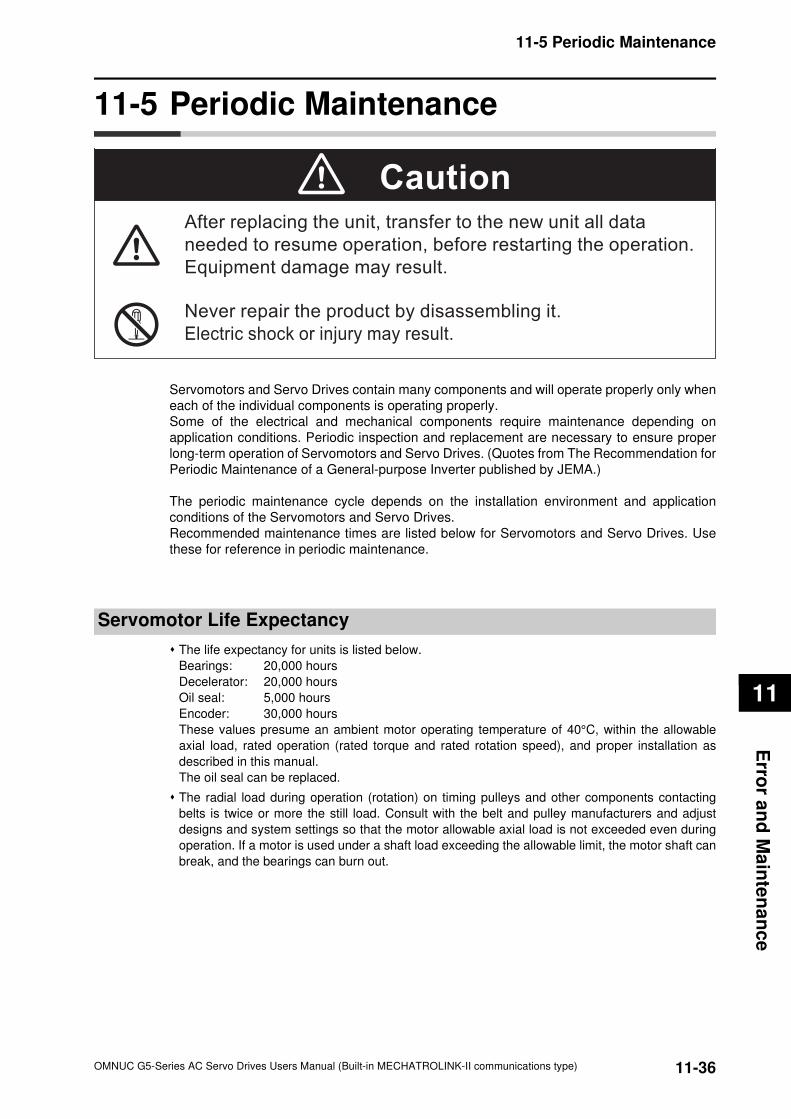
11-36
11-5 Periodic Maintenance
OMNUC G5-Series AC Servo Drives Users Manual (Built-in MECHATROLINK-II communications type)
11
Erro
r an
d M
ain
ten
an
ce
11-5 Periodic Maintenance
Servomotors and Servo Drives contain many components and will operate properly only when
each of the individual components is operating properly.
Some of the electrical and mechanical components require maintenance depending on
application conditions. Periodic inspection and replacement are necessary to ensure proper
long-term operation of Servomotors and Servo Drives. (Quotes from The Recommendation for
Periodic Maintenance of a General-purpose Inverter published by JEMA.)
The periodic maintenance cycle depends on the installation environment and application
conditions of the Servomotors and Servo Drives.
Recommended maintenance times are listed below for Servomotors and Servo Drives. Use
these for reference in periodic maintenance.
Servomotor Life Expectancy
The life expectancy for units is listed below.
Bearings: 20,000 hours
Decelerator: 20,000 hours
Oil seal: 5,000 hours
Encoder: 30,000 hours
These values presume an ambient motor operating temperature of 40°C, within the allowable
axial load, rated operation (rated torque and rated rotation speed), and proper installation as
described in this manual.
The oil seal can be replaced.
The radial load during operation (rotation) on timing pulleys and other components contacting
belts is twice or more the still load. Consult with the belt and pulley manufacturers and adjust
designs and system settings so that the motor allowable axial load is not exceeded even during
operation. If a motor is used under a shaft load exceeding the allowable limit, the motor shaft can
break, and the bearings can burn out.
CautionAfter replacing the unit, transfer to the new unit all data
needed to resume operation, before restarting the operation.
Equipment damage may result.
Never repair the product by disassembling it.
Electric shock or injury may result.
11-37
11-5 Periodic Maintenance
OMNUC G5-Series AC Servo Drives Users Manual (Built-in MECHATROLINK-II communications type)
11
Err
or
an
d M
ain
ten
an
ce
Servo Drive Life Expectancy
The life expectancy for units is listed below.
Aluminum electrolytic capacitors: 28,000 hours
(at an ambient drive operating temperature of 55°C, constant output of rated torque, constant
output of rated rotation speed, and installation as described in this manual)
Axial-flow fan: 10,000 to 30,000 hours (The limit depends on the operating conditions.)
Inrush current prevention relay: Approx. 20,000 operations (The limit depends on the operation
conditions.)
When using the Servo Drive in continuous operation, use fans or air conditioners to maintain an
ambient temperature below 40°C.
We recommend that ambient temperature and the power supply ON time be reduced as much as
possible to lengthen the service life of the drive.
The limit of aluminum electrolytic capacitors is greatly affected by the ambient operating
temperature. Generally, an increase of 10°C in the operating ambient temperature will reduce
capacitor service life by 50%.
For example, when the ambient operating temperature is 25°C, the life expectancy will be as
follows:
The aluminum electrolytic capacitors deteriorate even when the Servo Drive is stored with no
power supplied. If the Servo Drive is not used for a long time, we recommend a periodic inspection
and replacement schedule of 5 years.
If the Servomotor or Servo Drive is not to be used for a long time, or if they are to be used under
conditions worse than those described above, a periodic inspection schedule of 5 years is
recommended.
Upon request, OMRON will examine the Servo Drive and Servomotor and determine if a
replacement is required.
Life Expectacy (at 25°C) = Life Expectacy (at 55°C) × 255 - 25
10
= 224,000 hours
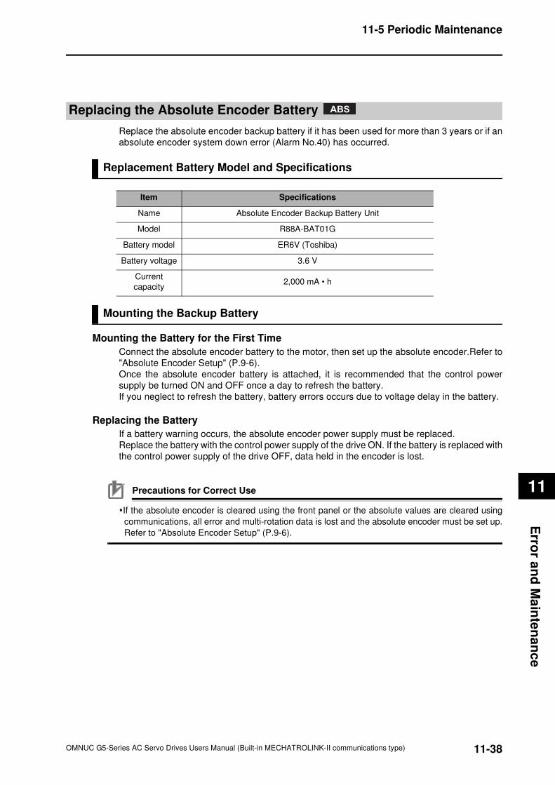
11-38
11-5 Periodic Maintenance
OMNUC G5-Series AC Servo Drives Users Manual (Built-in MECHATROLINK-II communications type)
11
Erro
r an
d M
ain
ten
an
ce
Replacing the Absolute Encoder Battery
Replace the absolute encoder backup battery if it has been used for more than 3 years or if an
absolute encoder system down error (Alarm No.40) has occurred.
Replacement Battery Model and Specifications
Mounting the Backup Battery
Mounting the Battery for the First Time
Connect the absolute encoder battery to the motor, then set up the absolute encoder.Refer to
"Absolute Encoder Setup" (P.9-6).
Once the absolute encoder battery is attached, it is recommended that the control power
supply be turned ON and OFF once a day to refresh the battery.
If you neglect to refresh the battery, battery errors occurs due to voltage delay in the battery.
Replacing the Battery
If a battery warning occurs, the absolute encoder power supply must be replaced.
Replace the battery with the control power supply of the drive ON. If the battery is replaced with
the control power supply of the drive OFF, data held in the encoder is lost.
Precautions for Correct Use
If the absolute encoder is cleared using the front panel or the absolute values are cleared using
communications, all error and multi-rotation data is lost and the absolute encoder must be set up.
Refer to "Absolute Encoder Setup" (P.9-6).
Item Specifications
Name Absolute Encoder Backup Battery Unit
Model R88A-BAT01G
Battery model ER6V (Toshiba)
Battery voltage 3.6 V
Current
capacity2,000 mA • h
ABS
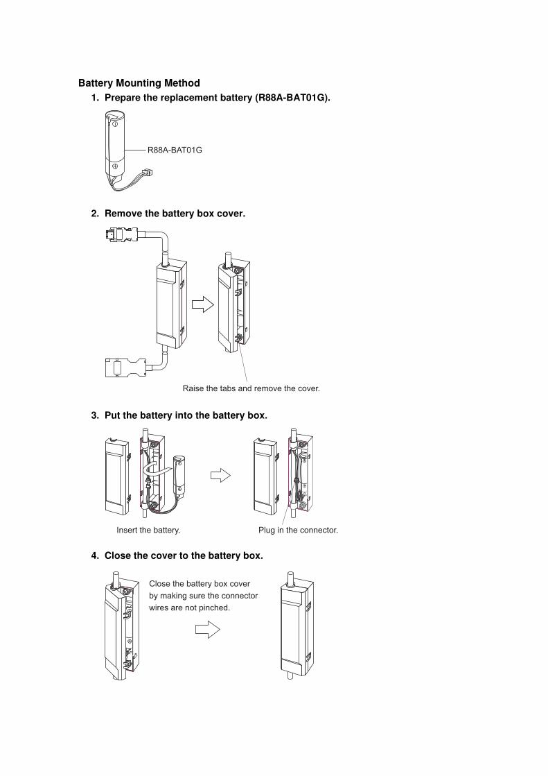
Battery Mounting Method
1. Prepare the replacement battery (R88A-BAT01G).
2. Remove the battery box cover.
3. Put the battery into the battery box.
4. Close the cover to the battery box.
R88A-BAT01G
Raise the tabs and remove the cover.
Plug in the connector.Insert the battery.
Close the battery box cover
by making sure the connector
wires are not pinched.
A
A
Appendix
This chapter provides connection examples using OMRON's PLC and Position
Controller, as well as a list of parameters.
A-1 Parameter List..............................................................A-1
OMNUC G5-Series AC Servo Drives Users Manual (Built-in MECHATROLINK-II communications type)
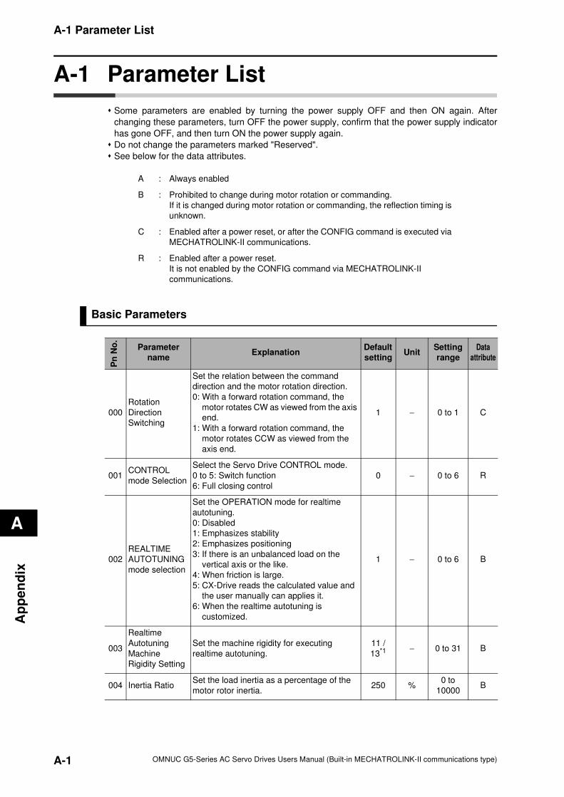
A-1 Parameter List
A
Ap
pe
nd
ix
A-1 Parameter List
Some parameters are enabled by turning the power supply OFF and then ON again. After
changing these parameters, turn OFF the power supply, confirm that the power supply indicator
has gone OFF, and then turn ON the power supply again.
Do not change the parameters marked "Reserved".
See below for the data attributes.
Basic Parameters
A : Always enabled
B : Prohibited to change during motor rotation or commanding.
If it is changed during motor rotation or commanding, the reflection timing is
unknown.
C : Enabled after a power reset, or after the CONFIG command is executed via
MECHATROLINK-II communications.
R : Enabled after a power reset.
It is not enabled by the CONFIG command via MECHATROLINK-II
communications.
Pn
No
.
Parameter
nameExplanation
Default
settingUnit
Setting
range
Data
attribute
000
Rotation
Direction
Switching
Set the relation between the command
direction and the motor rotation direction.
0: With a forward rotation command, the
motor rotates CW as viewed from the axis
end.
1: With a forward rotation command, the
motor rotates CCW as viewed from the
axis end.
1 − 0 to 1 C
001CONTROL
mode Selection
Select the Servo Drive CONTROL mode.
0 to 5: Switch function
6: Full closing control
0 − 0 to 6 R
002
REALTIME
AUTOTUNING
mode selection
Set the OPERATION mode for realtime
autotuning.
0: Disabled
1: Emphasizes stability
2: Emphasizes positioning
3: If there is an unbalanced load on the
vertical axis or the like.
4: When friction is large.
5: CX-Drive reads the calculated value and
the user manually can applies it.
6: When the realtime autotuning is
customized.
1 − 0 to 6 B
003
Realtime
Autotuning
Machine
Rigidity Setting
Set the machine rigidity for executing
realtime autotuning.
11 /
13*1 − 0 to 31 B
004 Inertia RatioSet the load inertia as a percentage of the
motor rotor inertia.250 %
0 to
10000B
A-1 OMNUC G5-Series AC Servo Drives Users Manual (Built-in MECHATROLINK-II communications type)
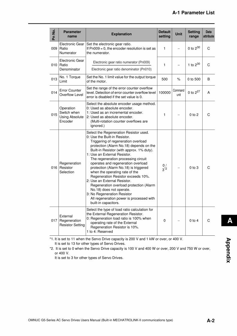
A-1 Parameter List
A
Ap
pe
nd
ix
009
Electronic Gear
Ratio
Numerator
Set the electronic gear ratio.
If Pn009 = 0, the encoder resolution is set as
the numerator.
1 − 0 to 230 C
010
Electronic Gear
Ratio
Denominator
1 − 1 to 230 C
013No. 1 Torque
Limit
Set the No. 1 limit value for the output torque
of the motor.500 % 0 to 500 B
014Error Counter
Overflow Level
Set the range of the error counter overflow
level. Detection of error counter overflow level
error is disabled if the set value is 0.
100000Command
unit0 to 227 A
015
Operation
Switch when
Using Absolute
Encoder
Select the absolute encoder usage method.
0: Used as absolute encoder.
1: Used as an incremental encoder.
2: Used as absolute encoder.
(Multi-rotation counter overflows are
ignored.)
1 − 0 to 2 C
016
Regeneration
Resistor
Selection
Select the Regeneration Resistor used.
0: Use the Built-in Resistor.
Triggering of regeneration overload
protection (Alarm No.18) depends on the
Built-in Resistor (with approx. 1% duty).
1: Use an External Resistor.
The regeneration processing circuit
operates and regeneration overload
protection (Alarm No.18) is triggered
when the operating rate of the
Regeneration Resistor exceeds 10%.
2: Use an External Resistor.
Regeneration overload protection (Alarm
No.18) does not operate.
3: No Regeneration Resistor
All regeneration power is processed with
built-in capacitors.
0 /
3*2 − 0 to 3 C
017
External
Regeneration
Resistor Setting
Select the type of load ratio calculation for
the External Regeneration Resistor.
0: Regeneration load ratio is 100% when
operating rate of the External
Regeneration Resistor is 10%.
1 to 4: Reserved
0 − 0 to 4 C
*1. It is set to 11 when the Servo Drive capacity is 200 V and 1 kW or over, or 400 V.
It is set to 13 for other types of Servo Drives.
*2. It is set to 0 when the Servo Drive capacity is 100 V and 400 W or over, 200 V and 750 W or over,
or 400 V.
It is set to 3 for other types of Servo Drives.
Pn
No
.
Parameter
nameExplanation
Default
settingUnit
Setting
range
Data
attribute
Electronic gear ratio denominator (Pn010)
Electronic gear ratio numerator (Pn009)
A-2OMNUC G5-Series AC Servo Drives Users Manual (Built-in MECHATROLINK-II communications type)
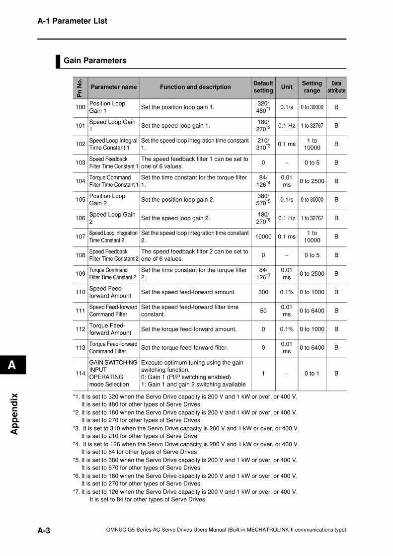
A-1 Parameter List
A
Ap
pe
nd
ix
Gain Parameters
Pn
No
.
Parameter name Function and descriptionDefault
settingUnit
Setting
range
Data
attribute
100Position Loop
Gain 1Set the position loop gain 1.
320/
480*1 0.1/s 0 to 30000 B
101Speed Loop Gain
1Set the speed loop gain 1.
180/
270*2 0.1 Hz 1 to 32767 B
102Speed Loop Integral
Time Constant 1
Set the speed loop integration time constant
1.
210/
310*3 0.1 ms1 to
10000B
103Speed Feedback
Filter Time Constant 1
The speed feedback filter 1 can be set to
one of 6 values.0 − 0 to 5 B
104Torque Command
Filter Time Constant 1
Set the time constant for the torque filter
1.
84/
126*40.01
ms0 to 2500 B
105Position Loop
Gain 2Set the position loop gain 2.
380/
570*5 0.1/s 0 to 30000 B
106Speed Loop Gain
2Set the speed loop gain 2.
180/
270*6 0.1 Hz 1 to 32767 B
107Speed Loop Integration
Time Constant 2
Set the speed loop integration time constant
2.10000 0.1 ms
1 to
10000B
108Speed Feedback
Filter Time Constant 2
The speed feedback filter 2 can be set to
one of 6 values.0 − 0 to 5 B
109Torque Command
Filter Time Constant 2
Set the time constant for the torque filter
2.
84/
126*70.01
ms0 to 2500 B
110Speed Feed-
forward AmountSet the speed feed-forward amount. 300 0.1% 0 to 1000 B
111Speed Feed-forward
Command Filter
Set the speed feed-forward filter time
constant.50
0.01
ms0 to 6400 B
112Torque Feed-
forward AmountSet the torque feed-forward amount. 0 0.1% 0 to 1000 B
113Torque Feed-forward
Command FilterSet the torque feed-forward filter. 0
0.01
ms0 to 6400 B
114
GAIN SWITCHING
INPUT
OPERATING
mode Selection
Execute optimum tuning using the gain
switching function.
0: Gain 1 (PI/P switching enabled)
1: Gain 1 and gain 2 switching available
1 − 0 to 1 B
*1. It is set to 320 when the Servo Drive capacity is 200 V and 1 kW or over, or 400 V.
It is set to 480 for other types of Serve Drives.
*2. It is set to 180 when the Servo Drive capacity is 200 V and 1 kW or over, or 400 V.
It is set to 270 for other types of Serve Drives
*3. It is set to 310 when the Servo Drive capacity is 200 V and 1 kW or over, or 400 V.
It is set to 210 for other types of Serve Drive
*4. It is set to 126 when the Servo Drive capacity is 200 V and 1 kW or over, or 400 V.
It is set to 84 for other types of Serve Drives
*5. It is set to 380 when the Servo Drive capacity is 200 V and 1 kW or over, or 400 V.
It is set to 570 for other types of Serve Drives.
*6. It is set to 180 when the Servo Drive capacity is 200 V and 1 kW or over, or 400 V.
It is set to 270 for other types of Serve Drives.
*7. It is set to 126 when the Servo Drive capacity is 200 V and 1 kW or over, or 400 V.
It is set to 84 for other types of Serve Drives.
A-3 OMNUC G5-Series AC Servo Drives Users Manual (Built-in MECHATROLINK-II communications type)
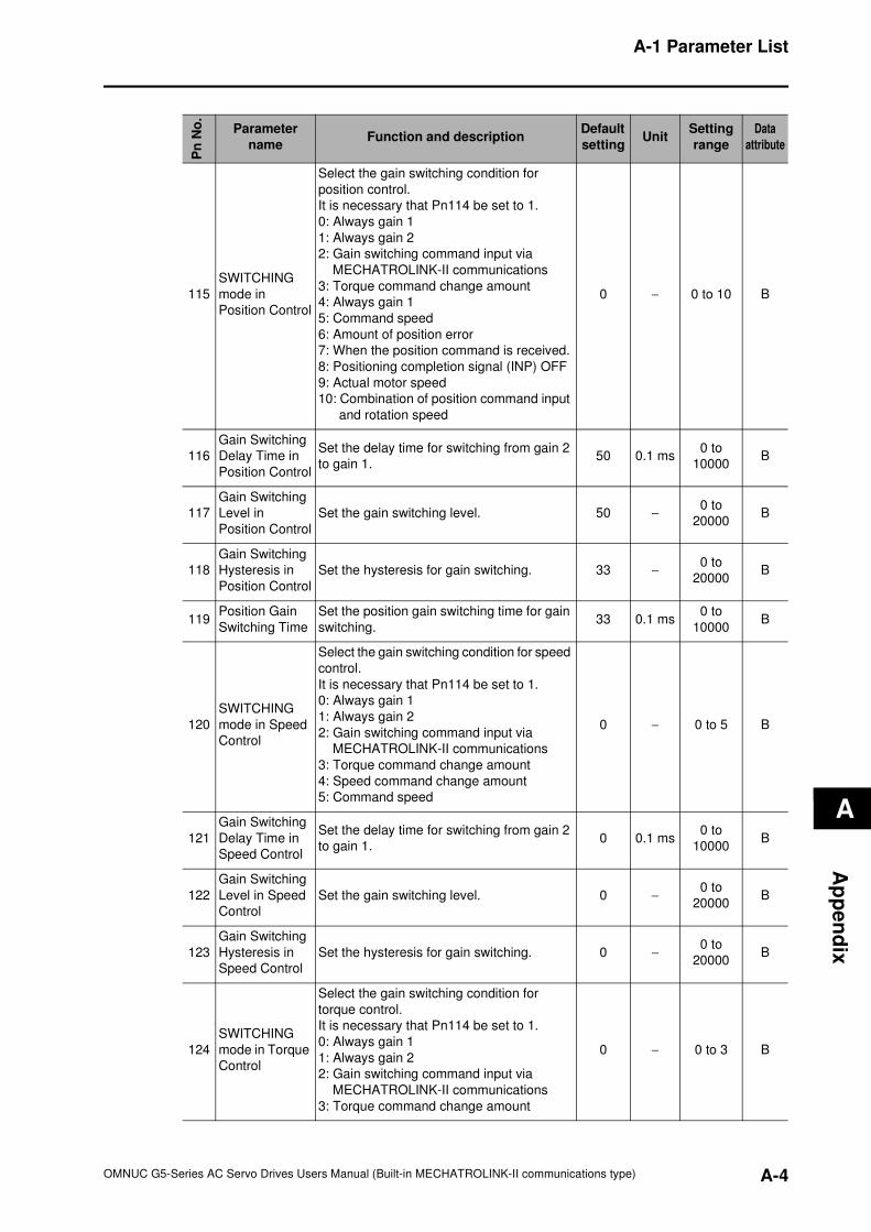
A-1 Parameter List
A
Ap
pe
nd
ix
Pn
No
.
Parameter
nameFunction and description
Default
settingUnit
Setting
range
Data
attribute
115
SWITCHING
mode in
Position Control
Select the gain switching condition for
position control.
It is necessary that Pn114 be set to 1.
0: Always gain 1
1: Always gain 2
2: Gain switching command input via
MECHATROLINK-II communications
3: Torque command change amount
4: Always gain 1
5: Command speed
6: Amount of position error
7: When the position command is received.
8: Positioning completion signal (INP) OFF
9: Actual motor speed
10: Combination of position command input
and rotation speed
0 − 0 to 10 B
116
Gain Switching
Delay Time in
Position Control
Set the delay time for switching from gain 2
to gain 1.50 0.1 ms
0 to
10000B
117
Gain Switching
Level in
Position Control
Set the gain switching level. 50 −0 to
20000B
118
Gain Switching
Hysteresis in
Position Control
Set the hysteresis for gain switching. 33 −0 to
20000B
119Position Gain
Switching Time
Set the position gain switching time for gain
switching.33 0.1 ms
0 to
10000B
120
SWITCHING
mode in Speed
Control
Select the gain switching condition for speed
control.
It is necessary that Pn114 be set to 1.
0: Always gain 1
1: Always gain 2
2: Gain switching command input via
MECHATROLINK-II communications
3: Torque command change amount
4: Speed command change amount
5: Command speed
0 − 0 to 5 B
121
Gain Switching
Delay Time in
Speed Control
Set the delay time for switching from gain 2
to gain 1.0 0.1 ms
0 to
10000B
122
Gain Switching
Level in Speed
Control
Set the gain switching level. 0 −0 to
20000B
123
Gain Switching
Hysteresis in
Speed Control
Set the hysteresis for gain switching. 0 −0 to
20000B
124
SWITCHING
mode in Torque
Control
Select the gain switching condition for
torque control.
It is necessary that Pn114 be set to 1.
0: Always gain 1
1: Always gain 2
2: Gain switching command input via
MECHATROLINK-II communications
3: Torque command change amount
0 − 0 to 3 B
A-4OMNUC G5-Series AC Servo Drives Users Manual (Built-in MECHATROLINK-II communications type)
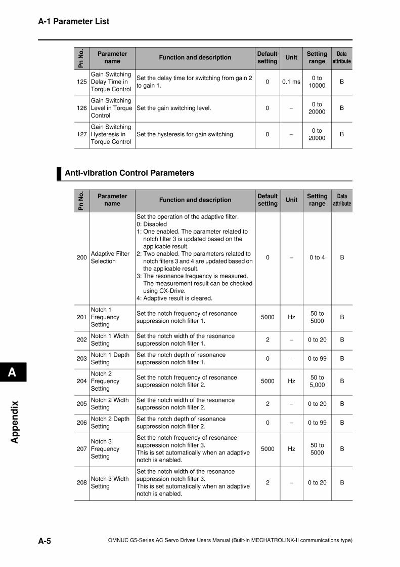
A-1 Parameter List
A
Ap
pe
nd
ix
Anti-vibration Control Parameters
125
Gain Switching
Delay Time in
Torque Control
Set the delay time for switching from gain 2
to gain 1.0 0.1 ms
0 to
10000B
126
Gain Switching
Level in Torque
Control
Set the gain switching level. 0 −0 to
20000B
127
Gain Switching
Hysteresis in
Torque Control
Set the hysteresis for gain switching. 0 −0 to
20000B
Pn
No
.
Parameter
nameFunction and description
Default
settingUnit
Setting
range
Data
attribute
200Adaptive Filter
Selection
Set the operation of the adaptive filter.
0: Disabled
1: One enabled. The parameter related to
notch filter 3 is updated based on the
applicable result.
2: Two enabled. The parameters related to
notch filters 3 and 4 are updated based on
the applicable result.
3: The resonance frequency is measured.
The measurement result can be checked
using CX-Drive.
4: Adaptive result is cleared.
0 − 0 to 4 B
201
Notch 1
Frequency
Setting
Set the notch frequency of resonance
suppression notch filter 1.5000 Hz
50 to
5000B
202Notch 1 Width
Setting
Set the notch width of the resonance
suppression notch filter 1.2 − 0 to 20 B
203Notch 1 Depth
Setting
Set the notch depth of resonance
suppression notch filter 1.0 − 0 to 99 B
204
Notch 2
Frequency
Setting
Set the notch frequency of resonance
suppression notch filter 2.5000 Hz
50 to
5,000B
205Notch 2 Width
Setting
Set the notch width of the resonance
suppression notch filter 2.2 − 0 to 20 B
206Notch 2 Depth
Setting
Set the notch depth of resonance
suppression notch filter 2.0 − 0 to 99 B
207
Notch 3
Frequency
Setting
Set the notch frequency of resonance
suppression notch filter 3.
This is set automatically when an adaptive
notch is enabled.
5000 Hz50 to
5000B
208Notch 3 Width
Setting
Set the notch width of the resonance
suppression notch filter 3.
This is set automatically when an adaptive
notch is enabled.
2 − 0 to 20 B
Pn
No
.
Parameter
nameFunction and description
Default
settingUnit
Setting
range
Data
attribute
A-5 OMNUC G5-Series AC Servo Drives Users Manual (Built-in MECHATROLINK-II communications type)
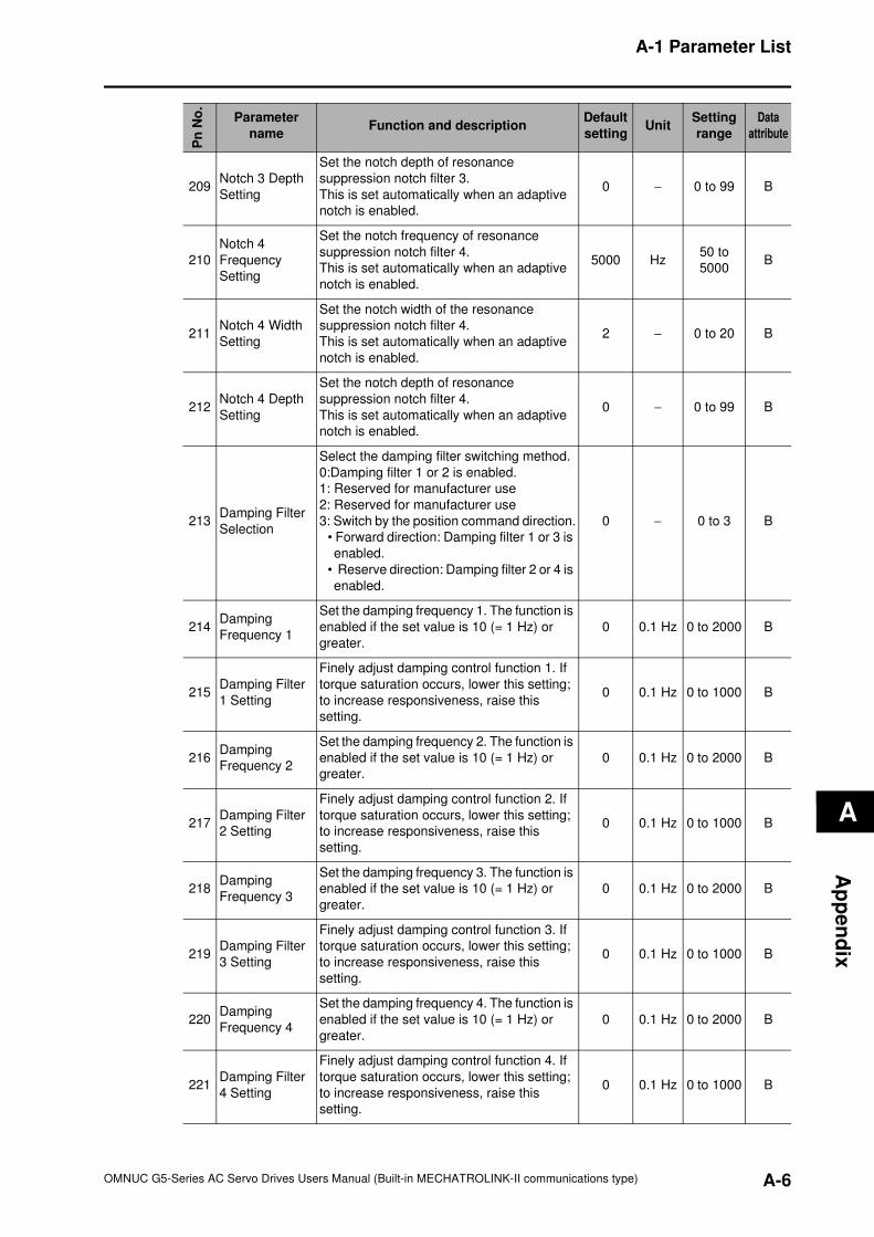
A-1 Parameter List
A
Ap
pe
nd
ix
209Notch 3 Depth
Setting
Set the notch depth of resonance
suppression notch filter 3.
This is set automatically when an adaptive
notch is enabled.
0 − 0 to 99 B
210
Notch 4
Frequency
Setting
Set the notch frequency of resonance
suppression notch filter 4.
This is set automatically when an adaptive
notch is enabled.
5000 Hz50 to
5000B
211Notch 4 Width
Setting
Set the notch width of the resonance
suppression notch filter 4.
This is set automatically when an adaptive
notch is enabled.
2 − 0 to 20 B
212Notch 4 Depth
Setting
Set the notch depth of resonance
suppression notch filter 4.
This is set automatically when an adaptive
notch is enabled.
0 − 0 to 99 B
213Damping Filter
Selection
Select the damping filter switching method.
0:Damping filter 1 or 2 is enabled.
1: Reserved for manufacturer use
2: Reserved for manufacturer use
3: Switch by the position command direction.
• Forward direction: Damping filter 1 or 3 is
enabled.
• Reserve direction: Damping filter 2 or 4 is
enabled.
0 − 0 to 3 B
214Damping
Frequency 1
Set the damping frequency 1. The function is
enabled if the set value is 10 (= 1 Hz) or
greater.
0 0.1 Hz 0 to 2000 B
215Damping Filter
1 Setting
Finely adjust damping control function 1. If
torque saturation occurs, lower this setting;
to increase responsiveness, raise this
setting.
0 0.1 Hz 0 to 1000 B
216Damping
Frequency 2
Set the damping frequency 2. The function is
enabled if the set value is 10 (= 1 Hz) or
greater.
0 0.1 Hz 0 to 2000 B
217Damping Filter
2 Setting
Finely adjust damping control function 2. If
torque saturation occurs, lower this setting;
to increase responsiveness, raise this
setting.
0 0.1 Hz 0 to 1000 B
218Damping
Frequency 3
Set the damping frequency 3. The function is
enabled if the set value is 10 (= 1 Hz) or
greater.
0 0.1 Hz 0 to 2000 B
219Damping Filter
3 Setting
Finely adjust damping control function 3. If
torque saturation occurs, lower this setting;
to increase responsiveness, raise this
setting.
0 0.1 Hz 0 to 1000 B
220Damping
Frequency 4
Set the damping frequency 4. The function is
enabled if the set value is 10 (= 1 Hz) or
greater.
0 0.1 Hz 0 to 2000 B
221Damping Filter
4 Setting
Finely adjust damping control function 4. If
torque saturation occurs, lower this setting;
to increase responsiveness, raise this
setting.
0 0.1 Hz 0 to 1000 B
Pn
No
.
Parameter
nameFunction and description
Default
settingUnit
Setting
range
Data
attribute
A-6OMNUC G5-Series AC Servo Drives Users Manual (Built-in MECHATROLINK-II communications type)
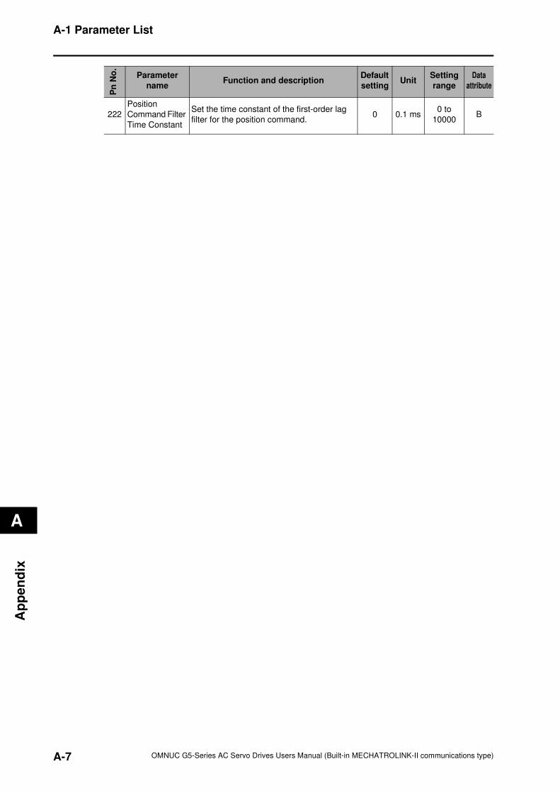
A-1 Parameter List
A
Ap
pe
nd
ix
222
Position
Command Filter
Time Constant
Set the time constant of the first-order lag
filter for the position command.0 0.1 ms
0 to
10000B
Pn
No
.
Parameter
nameFunction and description
Default
settingUnit
Setting
range
Data
attribute
A-7 OMNUC G5-Series AC Servo Drives Users Manual (Built-in MECHATROLINK-II communications type)
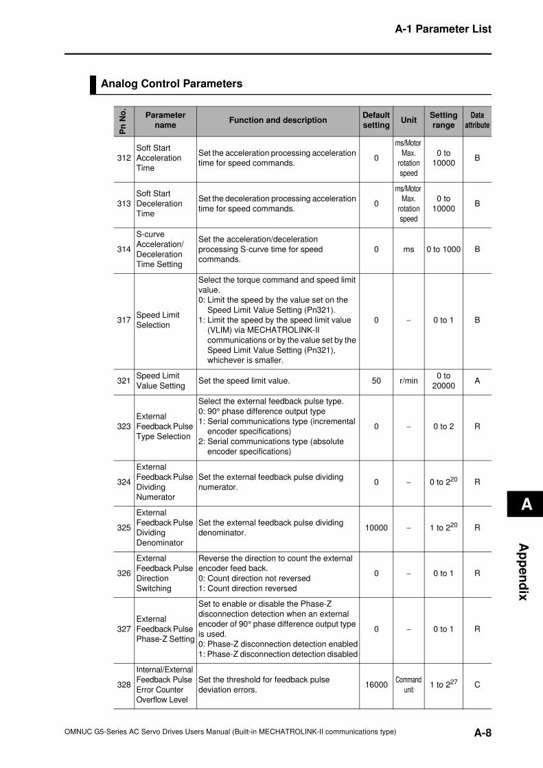
A-1 Parameter List
A
Ap
pe
nd
ix
Analog Control Parameters
Pn
No
.Parameter
nameFunction and description
Default
settingUnit
Setting
range
Data
attribute
312
Soft Start
Acceleration
Time
Set the acceleration processing acceleration
time for speed commands.0
ms/Motor
Max.
rotation
speed
0 to
10000B
313
Soft Start
Deceleration
Time
Set the deceleration processing acceleration
time for speed commands.0
ms/Motor
Max.
rotation
speed
0 to
10000B
314
S-curve
Acceleration/
Deceleration
Time Setting
Set the acceleration/deceleration
processing S-curve time for speed
commands.
0 ms 0 to 1000 B
317Speed Limit
Selection
Select the torque command and speed limit
value.
0: Limit the speed by the value set on the
Speed Limit Value Setting (Pn321).
1: Limit the speed by the speed limit value
(VLIM) via MECHATROLINK-II
communications or by the value set by the
Speed Limit Value Setting (Pn321),
whichever is smaller.
0 − 0 to 1 B
321Speed Limit
Value SettingSet the speed limit value. 50 r/min
0 to
20000A
323
External
Feedback Pulse
Type Selection
Select the external feedback pulse type.
0: 90° phase difference output type
1: Serial communications type (incremental
encoder specifications)
2: Serial communications type (absolute
encoder specifications)
0 − 0 to 2 R
324
External
Feedback Pulse
Dividing
Numerator
Set the external feedback pulse dividing
numerator.0 − 0 to 220 R
325
External
Feedback Pulse
Dividing
Denominator
Set the external feedback pulse dividing
denominator.10000 − 1 to 220 R
326
External
Feedback Pulse
Direction
Switching
Reverse the direction to count the external
encoder feed back.
0: Count direction not reversed
1: Count direction reversed
0 − 0 to 1 R
327
External
Feedback Pulse
Phase-Z Setting
Set to enable or disable the Phase-Z
disconnection detection when an external
encoder of 90° phase difference output type
is used.
0: Phase-Z disconnection detection enabled
1: Phase-Z disconnection detection disabled
0 − 0 to 1 R
328
Internal/External
Feedback Pulse
Error Counter
Overflow Level
Set the threshold for feedback pulse
deviation errors.16000
Command
unit1 to 227 C
A-8OMNUC G5-Series AC Servo Drives Users Manual (Built-in MECHATROLINK-II communications type)
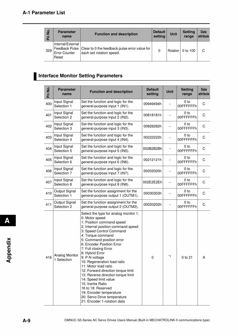
A-1 Parameter List
A
Ap
pe
nd
ix
Interface Monitor Setting Parameters
329
Internal/External
Feedback Pulse
Error Counter
Reset
Clear to 0 the feedback pulse error value for
each set rotation speed.0 Rotation 0 to 100 C
Pn
No
.
Parameter
nameFunction and description
Default
settingUnit
Setting
range
Data
attribute
Pn
No
.
Parameter
nameFunction and description
Default
settingUnit
Setting
range
Data
attribute
400Input Signal
Selection 1
Set the function and logic for the
general-purpose input 1 (IN1).00949494h −
0 to
00FFFFFFhC
401Input Signal
Selection 2
Set the function and logic for the
general-purpose input 2 (IN2).00818181h −
0 to
00FFFFFFhC
402Input Signal
Selection 3
Set the function and logic for the
general-purpose input 3 (IN3).00828282h −
0 to
00FFFFFFhC
403Input Signal
Selection 4
Set the function and logic for the
general-purpose input 4 (IN4).00222222h −
0 to
00FFFFFFhC
404Input Signal
Selection 5
Set the function and logic for the
general-purpose input 5 (IN5).002B2B2Bh −
0 to
00FFFFFFhC
405Input Signal
Selection 6
Set the function and logic for the
general-purpose input 6 (IN6).00212121h −
0 to
00FFFFFFhC
406Input Signal
Selection 7
Set the function and logic for the
general-purpose input 7 (IN7).00202020h −
0 to
00FFFFFFhC
407Input Signal
Selection 8
Set the function and logic for the
general-purpose input 8 (IN8).002E2E2Eh −
0 to
00FFFFFFhC
410Output Signal
Selection 1
Set the function assignment for the
general-purpose output 1 (OUTM1).00030303h −
0 to
00FFFFFFhC
411Output Signal
Selection 2
Set the function assignment for the
general-purpose output 2 (OUTM2).00020202h −
0 to
00FFFFFFhC
416Analog Monitor
1 Selection
Select the type for analog monitor 1.
0: Motor speed
1: Position command speed
2: Internal position command speed
3: Speed Control Command
4: Torque command
5: Command position error
6: Encoder Position Error
7: Full closing Error
8: Hybrid Error
9: P-N voltage
10: Regeneration load ratio
11: Motor load ratio
12: Forward direction torque limit
13: Reverse direction torque limit
14: Speed limit value
15: Inertia Ratio
16 to 18: Reserved
19: Encoder temperature
20: Servo Drive temperature
21: Encoder 1-rotation data
0 *1 0 to 21 A
A-9 OMNUC G5-Series AC Servo Drives Users Manual (Built-in MECHATROLINK-II communications type)
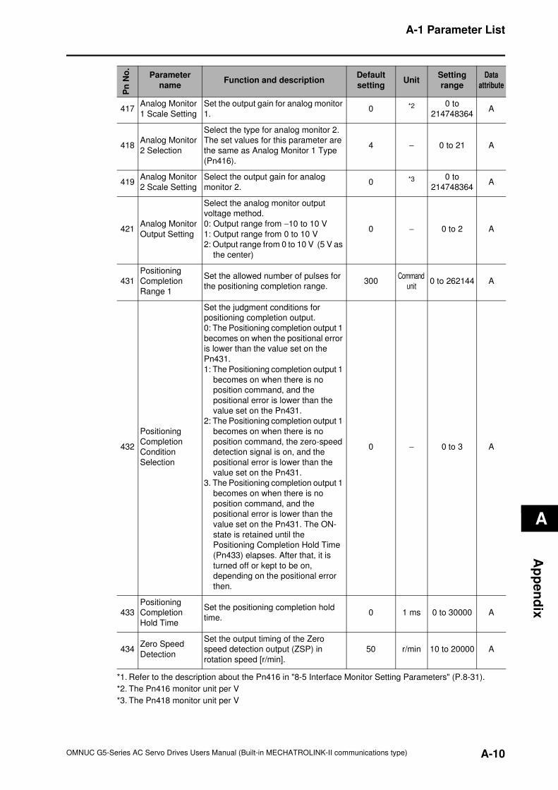
A-1 Parameter List
A
Ap
pe
nd
ix
417Analog Monitor
1 Scale Setting
Set the output gain for analog monitor
1.0 *2 0 to
214748364A
418Analog Monitor
2 Selection
Select the type for analog monitor 2.
The set values for this parameter are
the same as Analog Monitor 1 Type
(Pn416).
4 − 0 to 21 A
419Analog Monitor
2 Scale Setting
Select the output gain for analog
monitor 2.0 *3 0 to
214748364A
421Analog Monitor
Output Setting
Select the analog monitor output
voltage method.
0: Output range from −10 to 10 V
1: Output range from 0 to 10 V
2: Output range from 0 to 10 V (5 V as
the center)
0 − 0 to 2 A
431
Positioning
Completion
Range 1
Set the allowed number of pulses for
the positioning completion range.300
Command
unit0 to 262144 A
432
Positioning
Completion
Condition
Selection
Set the judgment conditions for
positioning completion output.
0: The Positioning completion output 1
becomes on when the positional error
is lower than the value set on the
Pn431.
1: The Positioning completion output 1
becomes on when there is no
position command, and the
positional error is lower than the
value set on the Pn431.
2: The Positioning completion output 1
becomes on when there is no
position command, the zero-speed
detection signal is on, and the
positional error is lower than the
value set on the Pn431.
3. The Positioning completion output 1
becomes on when there is no
position command, and the
positional error is lower than the
value set on the Pn431. The ON-
state is retained until the
Positioning Completion Hold Time
(Pn433) elapses. After that, it is
turned off or kept to be on,
depending on the positional error
then.
0 − 0 to 3 A
433
Positioning
Completion
Hold Time
Set the positioning completion hold
time.0 1 ms 0 to 30000 A
434Zero Speed
Detection
Set the output timing of the Zero
speed detection output (ZSP) in
rotation speed [r/min].
50 r/min 10 to 20000 A
*1. Refer to the description about the Pn416 in "8-5 Interface Monitor Setting Parameters" (P.8-31).
*2. The Pn416 monitor unit per V
*3. The Pn418 monitor unit per V
Pn
No
.
Parameter
nameFunction and description
Default
settingUnit
Setting
range
Data
attribute
A-10OMNUC G5-Series AC Servo Drives Users Manual (Built-in MECHATROLINK-II communications type)
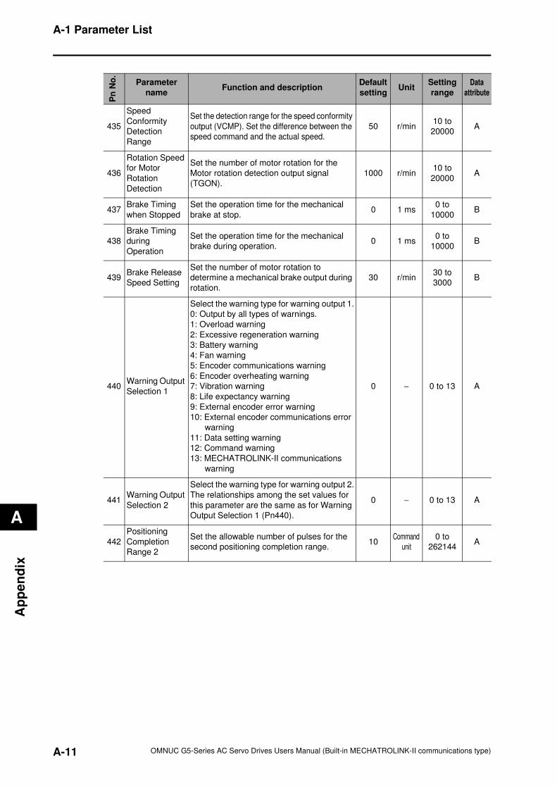
A-1 Parameter List
A
Ap
pe
nd
ix
Pn
No
.
Parameter
nameFunction and description
Default
settingUnit
Setting
range
Data
attribute
435
Speed
Conformity
Detection
Range
Set the detection range for the speed conformity
output (VCMP). Set the difference between the
speed command and the actual speed.
50 r/min10 to
20000A
436
Rotation Speed
for Motor
Rotation
Detection
Set the number of motor rotation for the
Motor rotation detection output signal
(TGON).
1000 r/min10 to
20000A
437Brake Timing
when Stopped
Set the operation time for the mechanical
brake at stop.0 1 ms
0 to
10000B
438
Brake Timing
during
Operation
Set the operation time for the mechanical
brake during operation.0 1 ms
0 to
10000B
439Brake Release
Speed Setting
Set the number of motor rotation to
determine a mechanical brake output during
rotation.
30 r/min30 to
3000B
440Warning Output
Selection 1
Select the warning type for warning output 1.
0: Output by all types of warnings.
1: Overload warning
2: Excessive regeneration warning
3: Battery warning
4: Fan warning
5: Encoder communications warning
6: Encoder overheating warning
7: Vibration warning
8: Life expectancy warning
9: External encoder error warning
10: External encoder communications error
warning
11: Data setting warning
12: Command warning
13: MECHATROLINK-II communications
warning
0 − 0 to 13 A
441Warning Output
Selection 2
Select the warning type for warning output 2.
The relationships among the set values for
this parameter are the same as for Warning
Output Selection 1 (Pn440).
0 − 0 to 13 A
442
Positioning
Completion
Range 2
Set the allowable number of pulses for the
second positioning completion range.10
Command
unit
0 to
262144A
A-11 OMNUC G5-Series AC Servo Drives Users Manual (Built-in MECHATROLINK-II communications type)
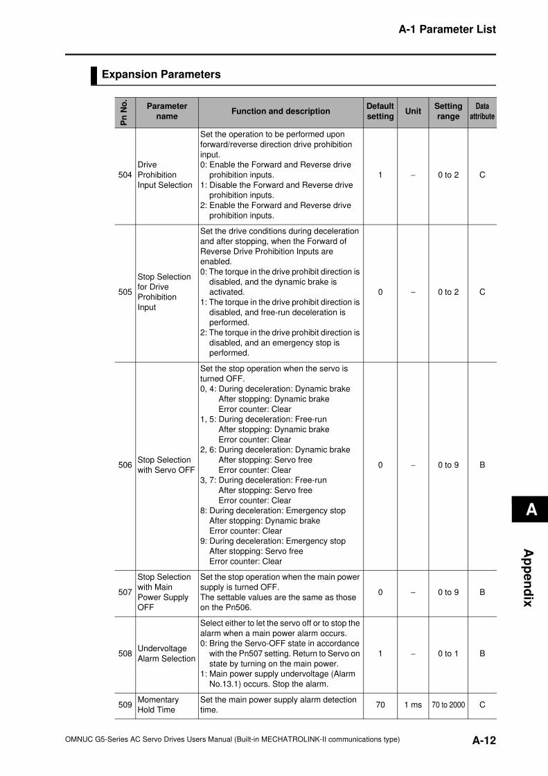
A-1 Parameter List
A
Ap
pe
nd
ix
Expansion Parameters
Pn
No
.
Parameter
nameFunction and description
Default
settingUnit
Setting
range
Data
attribute
504
Drive
Prohibition
Input Selection
Set the operation to be performed upon
forward/reverse direction drive prohibition
input.
0: Enable the Forward and Reverse drive
prohibition inputs.
1: Disable the Forward and Reverse drive
prohibition inputs.
2: Enable the Forward and Reverse drive
prohibition inputs.
1 − 0 to 2 C
505
Stop Selection
for Drive
Prohibition
Input
Set the drive conditions during deceleration
and after stopping, when the Forward of
Reverse Drive Prohibition Inputs are
enabled.
0: The torque in the drive prohibit direction is
disabled, and the dynamic brake is
activated.
1: The torque in the drive prohibit direction is
disabled, and free-run deceleration is
performed.
2: The torque in the drive prohibit direction is
disabled, and an emergency stop is
performed.
0 − 0 to 2 C
506Stop Selection
with Servo OFF
Set the stop operation when the servo is
turned OFF.
0, 4: During deceleration: Dynamic brake
After stopping: Dynamic brake
Error counter: Clear
1, 5: During deceleration: Free-run
After stopping: Dynamic brake
Error counter: Clear
2, 6: During deceleration: Dynamic brake
After stopping: Servo free
Error counter: Clear
3, 7: During deceleration: Free-run
After stopping: Servo free
Error counter: Clear
8: During deceleration: Emergency stop
After stopping: Dynamic brake
Error counter: Clear
9: During deceleration: Emergency stop
After stopping: Servo free
Error counter: Clear
0 − 0 to 9 B
507
Stop Selection
with Main
Power Supply
OFF
Set the stop operation when the main power
supply is turned OFF.
The settable values are the same as those
on the Pn506.
0 − 0 to 9 B
508Undervoltage
Alarm Selection
Select either to let the servo off or to stop the
alarm when a main power alarm occurs.
0: Bring the Servo-OFF state in accordance
with the Pn507 setting. Return to Servo on
state by turning on the main power.
1: Main power supply undervoltage (Alarm
No.13.1) occurs. Stop the alarm.
1 − 0 to 1 B
509Momentary
Hold Time
Set the main power supply alarm detection
time.70 1 ms 70 to 2000 C
A-12OMNUC G5-Series AC Servo Drives Users Manual (Built-in MECHATROLINK-II communications type)
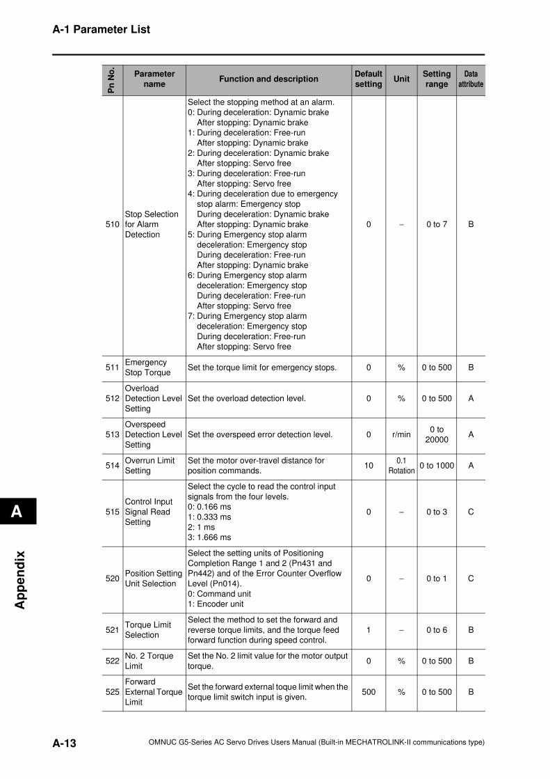
A-1 Parameter List
A
Ap
pe
nd
ix
510
Stop Selection
for Alarm
Detection
Select the stopping method at an alarm.
0: During deceleration: Dynamic brake
After stopping: Dynamic brake
1: During deceleration: Free-run
After stopping: Dynamic brake
2: During deceleration: Dynamic brake
After stopping: Servo free
3: During deceleration: Free-run
After stopping: Servo free
4: During deceleration due to emergency
stop alarm: Emergency stop
During deceleration: Dynamic brake
After stopping: Dynamic brake
5: During Emergency stop alarm
deceleration: Emergency stop
During deceleration: Free-run
After stopping: Dynamic brake
6: During Emergency stop alarm
deceleration: Emergency stop
During deceleration: Free-run
After stopping: Servo free
7: During Emergency stop alarm
deceleration: Emergency stop
During deceleration: Free-run
After stopping: Servo free
0 − 0 to 7 B
511Emergency
Stop TorqueSet the torque limit for emergency stops. 0 % 0 to 500 B
512
Overload
Detection Level
Setting
Set the overload detection level. 0 % 0 to 500 A
513
Overspeed
Detection Level
Setting
Set the overspeed error detection level. 0 r/min0 to
20000A
514Overrun Limit
Setting
Set the motor over-travel distance for
position commands.10
0.1
Rotation0 to 1000 A
515
Control Input
Signal Read
Setting
Select the cycle to read the control input
signals from the four levels.
0: 0.166 ms
1: 0.333 ms
2: 1 ms
3: 1.666 ms
0 − 0 to 3 C
520Position Setting
Unit Selection
Select the setting units of Positioning
Completion Range 1 and 2 (Pn431 and
Pn442) and of the Error Counter Overflow
Level (Pn014).
0: Command unit
1: Encoder unit
0 − 0 to 1 C
521Torque Limit
Selection
Select the method to set the forward and
reverse torque limits, and the torque feed
forward function during speed control.
1 − 0 to 6 B
522No. 2 Torque
Limit
Set the No. 2 limit value for the motor output
torque.0 % 0 to 500 B
525
Forward
External Torque
Limit
Set the forward external toque limit when the
torque limit switch input is given.500 % 0 to 500 B
Pn
No
.
Parameter
nameFunction and description
Default
settingUnit
Setting
range
Data
attribute
A-13 OMNUC G5-Series AC Servo Drives Users Manual (Built-in MECHATROLINK-II communications type)
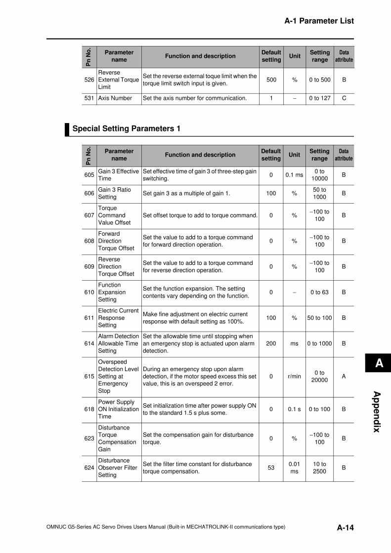
A-1 Parameter List
A
Ap
pe
nd
ix
Special Setting Parameters 1
526
Reverse
External Torque
Limit
Set the reverse external toque limit when the
torque limit switch input is given.500 % 0 to 500 B
531 Axis Number Set the axis number for communication. 1 − 0 to 127 C
Pn
No
.
Parameter
nameFunction and description
Default
settingUnit
Setting
range
Data
attribute
Pn
No
.
Parameter
nameFunction and description
Default
settingUnit
Setting
range
Data
attribute
605Gain 3 Effective
Time
Set effective time of gain 3 of three-step gain
switching.0 0.1 ms
0 to
10000B
606Gain 3 Ratio
SettingSet gain 3 as a multiple of gain 1. 100 %
50 to
1000B
607
Torque
Command
Value Offset
Set offset torque to add to torque command. 0 %−100 to
100B
608
Forward
Direction
Torque Offset
Set the value to add to a torque command
for forward direction operation.0 %
−100 to
100B
609
Reverse
Direction
Torque Offset
Set the value to add to a torque command
for reverse direction operation.0 %
−100 to
100B
610
Function
Expansion
Setting
Set the function expansion. The setting
contents vary depending on the function.0 − 0 to 63 B
611
Electric Current
Response
Setting
Make fine adjustment on electric current
response with default setting as 100%.100 % 50 to 100 B
614
Alarm Detection
Allowable Time
Setting
Set the allowable time until stopping when
an emergency stop is actuated upon alarm
detection.
200 ms 0 to 1000 B
615
Overspeed
Detection Level
Setting at
Emergency
Stop
During an emergency stop upon alarm
detection, if the motor speed excess this set
value, this is an overspeed 2 error.
0 r/min0 to
20000A
618
Power Supply
ON Initialization
Time
Set initialization time after power supply ON
to the standard 1.5 s plus some.0 0.1 s 0 to 100 B
623
Disturbance
Torque
Compensation
Gain
Set the compensation gain for disturbance
torque.0 %
−100 to
100B
624
Disturbance
Observer Filter
Setting
Set the filter time constant for disturbance
torque compensation.53
0.01
ms
10 to
2500B
A-14OMNUC G5-Series AC Servo Drives Users Manual (Built-in MECHATROLINK-II communications type)
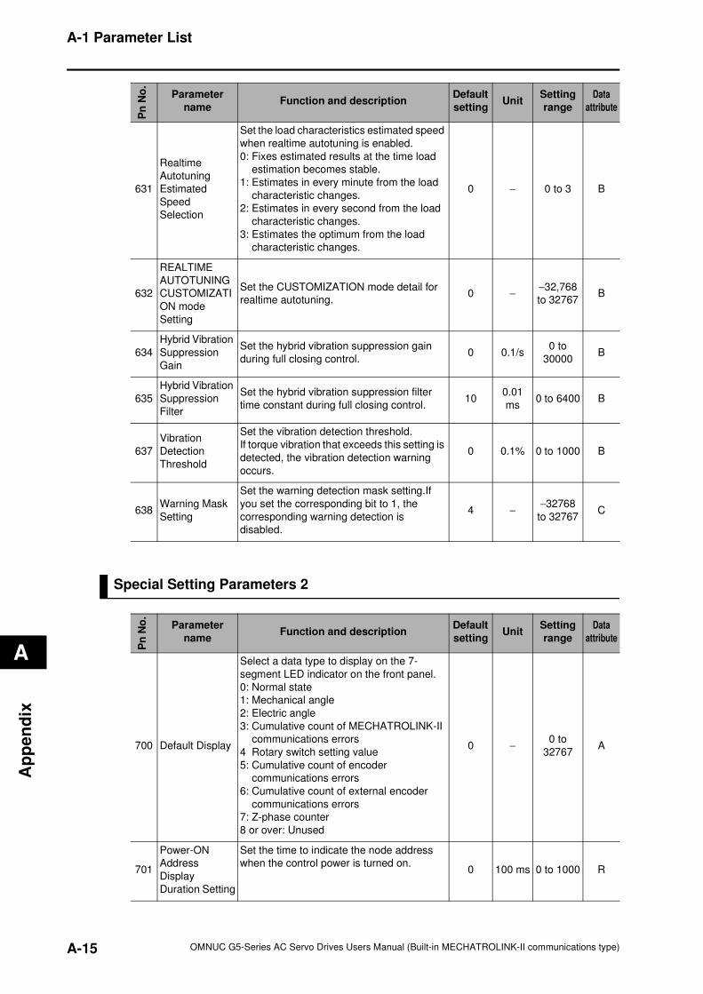
A-1 Parameter List
A
Ap
pe
nd
ix
Special Setting Parameters 2
631
Realtime
Autotuning
Estimated
Speed
Selection
Set the load characteristics estimated speed
when realtime autotuning is enabled.
0: Fixes estimated results at the time load
estimation becomes stable.
1: Estimates in every minute from the load
characteristic changes.
2: Estimates in every second from the load
characteristic changes.
3: Estimates the optimum from the load
characteristic changes.
0 − 0 to 3 B
632
REALTIME
AUTOTUNING
CUSTOMIZATI
ON mode
Setting
Set the CUSTOMIZATION mode detail for
realtime autotuning.0 −
−32,768
to 32767B
634
Hybrid Vibration
Suppression
Gain
Set the hybrid vibration suppression gain
during full closing control.0 0.1/s
0 to
30000B
635
Hybrid Vibration
Suppression
Filter
Set the hybrid vibration suppression filter
time constant during full closing control.10
0.01
ms0 to 6400 B
637
Vibration
Detection
Threshold
Set the vibration detection threshold.
If torque vibration that exceeds this setting is
detected, the vibration detection warning
occurs.
0 0.1% 0 to 1000 B
638Warning Mask
Setting
Set the warning detection mask setting.If
you set the corresponding bit to 1, the
corresponding warning detection is
disabled.
4 −−32768
to 32767C
Pn
No
.
Parameter
nameFunction and description
Default
settingUnit
Setting
range
Data
attribute
Pn
No
.
Parameter
nameFunction and description
Default
settingUnit
Setting
range
Data
attribute
700 Default Display
Select a data type to display on the 7-
segment LED indicator on the front panel.
0: Normal state
1: Mechanical angle
2: Electric angle
3: Cumulative count of MECHATROLINK-II
communications errors
4 Rotary switch setting value
5: Cumulative count of encoder
communications errors
6: Cumulative count of external encoder
communications errors
7: Z-phase counter
8 or over: Unused
0 −0 to
32767A
701
Power-ON
Address
Display
Duration Setting
Set the time to indicate the node address
when the control power is turned on.0 100 ms 0 to 1000 R
A-15 OMNUC G5-Series AC Servo Drives Users Manual (Built-in MECHATROLINK-II communications type)
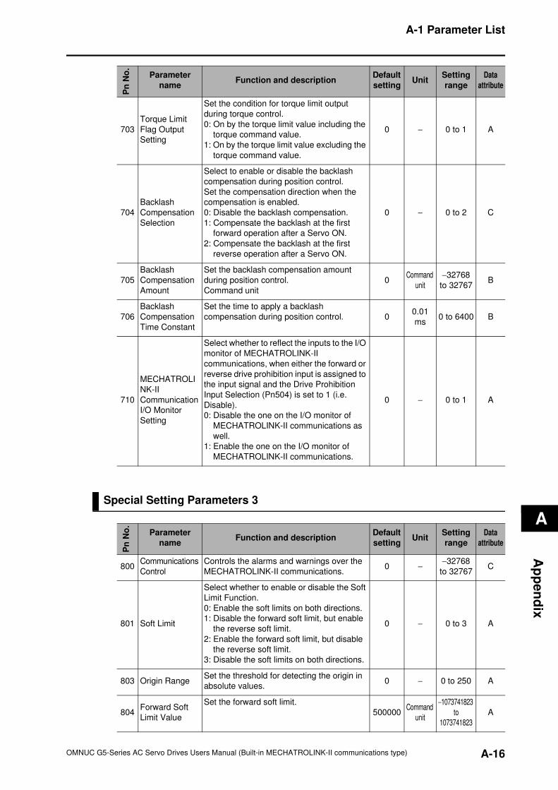
A-1 Parameter List
A
Ap
pe
nd
ix
Special Setting Parameters 3
703
Torque Limit
Flag Output
Setting
Set the condition for torque limit output
during torque control.
0: On by the torque limit value including the
torque command value.
1: On by the torque limit value excluding the
torque command value.
0 − 0 to 1 A
704
Backlash
Compensation
Selection
Select to enable or disable the backlash
compensation during position control.
Set the compensation direction when the
compensation is enabled.
0: Disable the backlash compensation.
1: Compensate the backlash at the first
forward operation after a Servo ON.
2: Compensate the backlash at the first
reverse operation after a Servo ON.
0 − 0 to 2 C
705
Backlash
Compensation
Amount
Set the backlash compensation amount
during position control.
Command unit
0Command
unit
−32768
to 32767B
706
Backlash
Compensation
Time Constant
Set the time to apply a backlash
compensation during position control. 00.01
ms0 to 6400 B
710
MECHATROLI
NK-II
Communication
I/O Monitor
Setting
Select whether to reflect the inputs to the I/O
monitor of MECHATROLINK-II
communications, when either the forward or
reverse drive prohibition input is assigned to
the input signal and the Drive Prohibition
Input Selection (Pn504) is set to 1 (i.e.
Disable).
0: Disable the one on the I/O monitor of
MECHATROLINK-II communications as
well.
1: Enable the one on the I/O monitor of
MECHATROLINK-II communications.
0 − 0 to 1 A
Pn
No
.
Parameter
nameFunction and description
Default
settingUnit
Setting
range
Data
attribute
Pn
No
.
Parameter
nameFunction and description
Default
settingUnit
Setting
range
Data
attribute
800Communications
Control
Controls the alarms and warnings over the
MECHATROLINK-II communications.0 −
−32768
to 32767C
801 Soft Limit
Select whether to enable or disable the Soft
Limit Function.
0: Enable the soft limits on both directions.
1: Disable the forward soft limit, but enable
the reverse soft limit.
2: Enable the forward soft limit, but disable
the reverse soft limit.
3: Disable the soft limits on both directions.
0 − 0 to 3 A
803 Origin RangeSet the threshold for detecting the origin in
absolute values.0 − 0 to 250 A
804Forward Soft
Limit Value
Set the forward soft limit.
500000Command
unit
−1073741823
to
1073741823
A
A-16OMNUC G5-Series AC Servo Drives Users Manual (Built-in MECHATROLINK-II communications type)
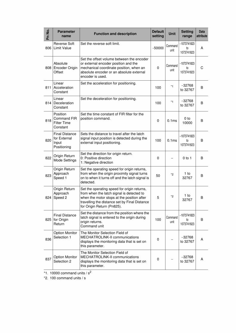
806
Reverse Soft
Limit Value
Set the reverse soft limit.
−500000Command
unit
−1073741823
to
1073741823
A
808
Absolute
Encoder Origin
Offset
Set the offset volume between the encoder
or external encoder position and the
mechanical coordinate position, when an
absolute encoder or an absolute external
encoder is used.
0Command
unit
−1073741823
to
1073741823
C
811
Linear
Acceleration
Constant
Set the acceleration for positioning.
100 *1 −32768
to 32767B
814
Linear
Deceleration
Constant
Set the deceleration for positioning.
100 *1 −32768
to 32767B
818
Position
Command FIR
Filter Time
Constant
Set the time constant of FIR filter for the
position command.0 0.1ms
0 to
10000B
820
Final Distance
for External
Input
Positioning
Sets the distance to travel after the latch
signal input position is detected during the
external input positioning.100 0.1ms
−1073741823
to
1073741823
B
822Origin Return
Mode Settings
Set the direction for origin return.
0: Positive direction
1: Negative direction
0 − 0 to 1 B
823
Origin Return
Approach
Speed 1
Set the operating speed for origin returns,
from when the origin proximity signal turns
on to when it turns off and the latch signal is
detected.
50 *2 1 to
32767B
824
Origin Return
Approach
Speed 2
Set the operating speed for origin returns,
from when the latch signal is detected to
when the motor stops at the position after
travelling the distance set by Final Distance
for Origin Return (Pn825).
5 *2 1 to
32767B
825
Final Distance
for Origin
Return
Set the distance from the position where the
latch signal is entered to the origin during
origin returns.
Command unit
100Command
unit
−1073741823
to
1073741823
B
836
Option Monitor
Selection 1
The Monitor Selection Field of
MECHATROLINK-II communications
displays the monitoring data that is set on
this parameter.
0 −−32768
to 32767A
837Option Monitor
Selection 2
The Monitor Selection Field of
MECHATROLINK-II communications
displays the monitoring data that is set on
this parameter.
0 −−32768
to 32767A
*1. 10000 command units / s2
*2. 100 command units / s
Pn
No
.
Parameter
nameFunction and description
Default
settingUnit
Setting
range
Data
attribute