Embed Size (px)
Citation preview

Digital System Test and Testable Design

wwwwwwwwwwww

Zainalabedin Navabi
Digital System Test and Testable Design
Using HDL Models and Architectures
Zainalabedin NavabiWorcester Polytechnic Institute Department of Electrical & Computer EngineeringWorcester, [email protected]
ISBN 978-1-4419-7547-8 e-ISBN 978-1-4419-7548-5DOI 10.1007/978-1-4419-7548-5Springer New York Dordrecht Heidelberg London
Springer Science+Business Media, LLC 2011All rights reserved. This work may not be translated or copied in whole or in part without the written permission of the publisher (Springer Science+Business Media, LLC, 233 Spring Street, New York, NY 10013, USA), except for brief excerpts in connection with reviews or scholarly analysis. Use in connection with any form of information storage and retrieval, electronic adaptation, computer software, or by similar or dissimilar methodology now known or hereafter developed is forbidden.The use in this publication of trade names, trademarks, service marks, and similar terms, even if they are not identified as such, is not to be taken as an expression of opinion as to whether or not they are subject to proprietary rights.
Printed on acid-free paper
Springer is part of Springer Science+Business Media (www.springer.com)

This book is dedicated to my wife, Irma, and sons Aarash and Arvand.

wwwwwwwwwwww

vii
This is a book on test and testability of digital circuits in which test is spoken in the language of design. In this book, the concepts of testing and testability are treated together with digital design practices and methodologies. We show how testing digital circuits designing testable circuits can take advantage of some of the well-established RT-level design and verification methodologies and tools. The book uses Verilog models and testbenches for implementing and explaining fault simula-tion and test generation algorithms. In the testability part, it describes various scan and BIST meth-ods in Verilog and uses Verilog testbenches as virtual testers to examine and evaluate these testability methods. In designing testable circuits, we use Verilog testbenches to evaluate, and thus improve testability of a design.
The first part of the book develops Verilog test environments that can perform gate-level fault simulation and test generation. This part uses Verilog PLI along with Verilog’s powerful testbench development facilities for modeling hardware and programing test environments. The second part of the book uses Verilog as a hardware design tool for describing DFT and BIST hardware. In this part, Verilog is used as a hardware description language describing synthesizable testable hardware. Throughout the book, Verilog simulation helps developing and evaluating test methods and test-ability hardware constructs.
This book professes a new approach to teaching test. Use of Verilog and Verilog PLI for test applications is what distinguishes this book from other test and testability books. As HDLs were used in late 1970s for teaching computer architectures, today, HDLs can be used to illustrate test methodologies and testability architectures that are otherwise illustrated informally by flow charts, graphs, and block diagrams. Verilog eliminates ambiguities in test algorithms and BIST and DFT hardware architectures, and it clearly describes the architecture of the testability hardware and its test sessions. Describing on-chip test hardware in Verilog helps evaluating the related algorithms in terms of hardware overhead and timing and thus feasibility of using them on SoC chips. Further support for this approach comes in use of testbenches. Using PLI in developing testbenches and virtual testers gives us a powerful programing tool interfaced with hardware described in Verilog. This mixed hardware/software environment facilitates the description of complex test programs and test strategies.
Preface

wwwwwwwwwwww

ix
When I first thought of using a hardware description language for test purposes, I started using VHDL models for test purposes in my course on digital system testing at the University of Tehran. After several years of teaching this course, we switched to Verilog and a set of library components that facilitated this usage of Verilog was developed. The groups of students who developed the software and helped me in the formation of the materials are important contributors to this work. The student, who took the responsibility for the development of the software package was Nastaran Nemati. She managed the development of the complete library by the time of her graduation in 2010. Her efforts contributed significantly to this work. I thank my students at Worcester Polytechnic Institute in Massachusetts, USA, and the University of Tehran for sitting at my presentations or watching them online and making useful suggestions.
When the actual development of the book started, my graduate student, Fatemeh (Negin) Javaheri, became the key person with whom I discussed my ideas. She was always available for consulting with me and her ideas helped significantly in shaping the structure of the book. She later took responsibility for developing the material for the chapter on test compression. Negin continues to work with me on my research, and she is looking forward to the next book that I want to write. Another important contributor, also a graduate student at the University of Tehran, is Somayeh Sadeghi Kohan. Somayeh developed the materials for the chapter on boundary scan, and in the final stages of this work she was very helpful reviewing chapters and suggesting changes. The feedbacks she provided and changes she suggested were most helpful. Nastaran Nemati helped developing the HDL chapter, and Parisa Kabiri and Atie Lotfi also contributed to some of the chapters and helped reviewing the materials.
As always, and as it is with all my books, Fatemeh Asgari, who has been my assistant for the past 20 years, became responsible for managing the project. She managed the group of students who did research, developed software, collected materials, and prepared the final manuscript with its text and artwork. Fatemeh’s support and management of my writing and research projects have always been key to the successful completion of these projects. I cannot thank her enough for the work she has done for me throughout the years.
My work habits and time I spend away from my family working on my research and writing projects have been particularly difficult for them. However, I have always had their support, under-standing, and encouragement for all my projects. My wife, Irma, has always been a great help for me providing an environment that I can spend hours and hours on my writing projects. I thank Irma, and my sons Aarash and Arvand.
August 2010 Zainalabedin Navabi [email protected]
Acknowledgments

wwwwwwwwwwww

xi
Contents
1 Basic of Test and Role of HDLs ...................................................................................... 11.1 Design and Test ........................................................................................................ 1
1.1.1 RTL Design Process ..................................................................................... 11.1.2 Postmanufacturing Test ................................................................................ 4
1.2 Test Concerns ........................................................................................................... 81.2.1 Test Methods ................................................................................................ 91.2.2 Testability Methods ...................................................................................... 111.2.3 Testing Methods ........................................................................................... 131.2.4 Cost of Test ................................................................................................... 13
1.3 HDLs in Digital System Test .................................................................................... 151.3.1 Hardware Modeling ...................................................................................... 151.3.2 Developing Test Methods ............................................................................. 151.3.3 Virtual Testers ............................................................................................... 161.3.4 Testability Hardware Evaluation .................................................................. 161.3.5 Protocol Aware ATE ..................................................................................... 16
1.4 ATE Architecture and Instrumentation..................................................................... 171.4.1 Digital Stimulus and Measure Instruments .................................................. 171.4.2 DC Instrumentation ...................................................................................... 171.4.3 AC Instrumentation ...................................................................................... 171.4.4 RF Instrumentation ....................................................................................... 181.4.5 Ate ................................................................................................................ 18
1.5 Summary .................................................................................................................. 19References .......................................................................................................................... 20
2 Verilog HDL for Design and Test .................................................................................... 212.1 Motivations of Using HDLs for Developing Test Methods ..................................... 212.2 Using Verilog in Design ........................................................................................... 22
2.2.1 Using Verilog for Simulation ....................................................................... 222.2.2 Using Verilog for Synthesis .......................................................................... 23
2.3 Using Verilog in Test ................................................................................................ 242.3.1 Good Circuit Analysis .................................................................................. 242.3.2 Fault List Compilation and Testability Analysis .......................................... 242.3.3 Fault Simulation ........................................................................................... 252.3.4 Test Generation ............................................................................................. 262.3.5 Testability Hardware Design ........................................................................ 26

xii Contents
2.4 Basic Structures of Verilog ....................................................................................... 272.4.1 Modules, Ports, Wires, and Variables ........................................................... 282.4.2 Levels of Abstraction ................................................................................... 292.4.3 Logic Value System ...................................................................................... 29
2.5 Combinational Circuits ............................................................................................ 302.5.1 Transistor-Level Description ........................................................................ 302.5.2 Gate-Level Description ................................................................................ 312.5.3 Equation-Level Description .......................................................................... 322.5.4 Procedural Level Description ....................................................................... 322.5.5 Instantiating Other Modules ......................................................................... 34
2.6 Sequential Circuits ................................................................................................... 362.6.1 Registers and Shift Registers ........................................................................ 362.6.2 State Machine Coding .................................................................................. 36
2.7 A Complete Example (Adding Machine) ................................................................. 422.7.1 Control/Data Partitioning ............................................................................. 422.7.2 Adding Machine Specification ..................................................................... 422.7.3 CPU Implementation .................................................................................... 43
2.8 Testbench Techniques ............................................................................................... 482.8.1 Testbench Techniques ................................................................................... 482.8.2 A Simple Combinational Testbench ............................................................. 492.8.3 A Simple Sequential Testbench .................................................................... 502.8.4 Limiting Data Sets ........................................................................................ 512.8.5 Synchronized Data and Response Handling ................................................ 512.8.6 Random Time Intervals ................................................................................ 522.8.7 Text IO .......................................................................................................... 532.8.8 Simulation Code Coverage ........................................................................... 54
2.9 PLI Basics ................................................................................................................ 562.9.1 Access Routines ........................................................................................... 572.9.2 Steps for HDL/PLI Implementation ............................................................. 572.9.3 Fault Injection in the HDL/PLI Environment .............................................. 59
2.10 Summary .................................................................................................................. 62References .......................................................................................................................... 62
3 Fault and Defect Modeling .............................................................................................. 633.1 Fault Modeling ......................................................................................................... 63
3.1.1 Fault Abstraction .......................................................................................... 643.1.2 Functional Faults .......................................................................................... 673.1.3 Structural Faults ........................................................................................... 68
3.2 Structural Gate Level Faults ..................................................................................... 713.2.1 Recognizing Faults ....................................................................................... 713.2.2 Stuck-Open Faults ........................................................................................ 723.2.3 Stuck-at-0 Faults ........................................................................................... 723.2.4 Stuck-at-1 Faults ........................................................................................... 733.2.5 Bridging Faults ............................................................................................. 733.2.6 State-Dependent Faults ................................................................................. 753.2.7 Multiple Faults ............................................................................................. 753.2.8 Single Stuck-at Structural Faults .................................................................. 773.2.9 Detecting Single Stuck-at Faults .................................................................. 83

xiiiContents
3.3 Issues Related to Gate Level Faults .......................................................................... 843.3.1 Detecting Bridging Faults ............................................................................ 843.3.2 Undetectable Faults ...................................................................................... 853.3.3 Redundant Faults .......................................................................................... 85
3.4 Fault Collapsing ....................................................................................................... 863.4.1 Indistinguishable Faults ................................................................................ 863.4.2 Equivalent Single Stuck-at Faults................................................................. 863.4.3 Gate-Oriented Fault Collapsing .................................................................... 873.4.4 Line-Oriented Fault Collapsing .................................................................... 893.4.5 Problem with Reconvergent Fanouts ............................................................ 913.4.6 Dominance Fault Collapsing ........................................................................ 92
3.5 Fault Collapsing in Verilog ....................................................................................... 953.5.1 Verilog Testbench for Fault Collapsing ........................................................ 953.5.2 PLI Implementation of Fault Collapsing ...................................................... 97
3.6 Summary .................................................................................................................. 100References .......................................................................................................................... 101
4 Fault Simulation Applications and Methods ................................................................. 1034.1 Fault Simulation ....................................................................................................... 103
4.1.1 Gate-Level Fault Simulation ........................................................................ 1034.1.2 Fault Simulation Requirements .................................................................... 1044.1.3 An HDL Environment .................................................................................. 1054.1.4 Sequential Circuit Fault Simulation ............................................................. 1114.1.5 Fault Dropping ............................................................................................. 1114.1.6 Related Terminologies .................................................................................. 111
4.2 Fault Simulation Applications .................................................................................. 1124.2.1 Fault Coverage .............................................................................................. 1134.2.2 Fault Simulation in Test Generation ............................................................. 1144.2.3 Fault Dictionary Creation ............................................................................. 117
4.3 Fault Simulation Technologies ................................................................................. 1224.3.1 Serial Fault Simulation ................................................................................. 1244.3.2 Parallel Fault Simulation .............................................................................. 1274.3.3 Concurrent Fault Simulation ........................................................................ 1314.3.4 Deductive Fault Simulation .......................................................................... 1334.3.5 Comparison of Deductive Fault Simulation ................................................. 1374.3.6 Critical Path Tracing Fault Simulation ......................................................... 1374.3.7 Differential Fault Simulation ........................................................................ 140
4.4 Summary .................................................................................................................. 141References .......................................................................................................................... 141
5 Test Pattern Generation Methods and Algorithms ....................................................... 1435.1 Test Generation Basics ............................................................................................. 143
5.1.1 Boolean Difference ....................................................................................... 1435.1.2 Test Generation Process ............................................................................... 1455.1.3 Fault and Tests .............................................................................................. 1465.1.4 Terminologies and Definitions ..................................................................... 147
5.2 Controllability and Observability ............................................................................. 1475.2.1 Controllability .............................................................................................. 1485.2.2 Observability ................................................................................................ 148
xiv Contents
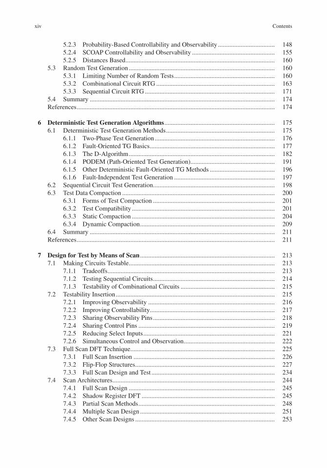
5.2.3 Probability-Based Controllability and Observability ................................... 1485.2.4 SCOAP Controllability and Observability ................................................... 1555.2.5 Distances Based ............................................................................................ 160
5.3 Random Test Generation .......................................................................................... 1605.3.1 Limiting Number of Random Tests .............................................................. 1605.3.2 Combinational Circuit RTG ......................................................................... 1635.3.3 Sequential Circuit RTG ................................................................................ 171
5.4 Summary .................................................................................................................. 174References .......................................................................................................................... 174
6 Deterministic Test Generation Algorithms .................................................................... 1756.1 Deterministic Test Generation Methods ................................................................... 175
6.1.1 Two-Phase Test Generation .......................................................................... 1766.1.2 Fault-Oriented TG Basics ............................................................................. 1776.1.3 The D-Algorithm .......................................................................................... 1826.1.4 PODEM (Path-Oriented Test Generation).................................................... 1916.1.5 Other Deterministic Fault-Oriented TG Methods ........................................ 1966.1.6 Fault-Independent Test Generation .............................................................. 197
6.2 Sequential Circuit Test Generation ........................................................................... 1986.3 Test Data Compaction .............................................................................................. 200
6.3.1 Forms of Test Compaction ........................................................................... 2016.3.2 Test Compatibility ........................................................................................ 2016.3.3 Static Compaction ........................................................................................ 2046.3.4 Dynamic Compaction ................................................................................... 209
6.4 Summary .................................................................................................................. 211References .......................................................................................................................... 211
7 Design for Test by Means of Scan ................................................................................... 2137.1 Making Circuits Testable .......................................................................................... 213
7.1.1 Tradeoffs ....................................................................................................... 2137.1.2 Testing Sequential Circuits ........................................................................... 2147.1.3 Testability of Combinational Circuits .......................................................... 215
7.2 Testability Insertion .................................................................................................. 2157.2.1 Improving Observability .............................................................................. 2167.2.2 Improving Controllability ............................................................................. 2177.2.3 Sharing Observability Pins ........................................................................... 2187.2.4 Sharing Control Pins .................................................................................... 2197.2.5 Reducing Select Inputs ................................................................................. 2217.2.6 Simultaneous Control and Observation ........................................................ 222
7.3 Full Scan DFT Technique ......................................................................................... 2257.3.1 Full Scan Insertion ....................................................................................... 2267.3.2 Flip-Flop Structures ...................................................................................... 2277.3.3 Full Scan Design and Test ............................................................................ 234
7.4 Scan Architectures .................................................................................................... 2447.4.1 Full Scan Design .......................................................................................... 2457.4.2 Shadow Register DFT .................................................................................. 2457.4.3 Partial Scan Methods .................................................................................... 2487.4.4 Multiple Scan Design ................................................................................... 2517.4.5 Other Scan Designs ...................................................................................... 253

xvContents
7.5 RT Level Scan Design .............................................................................................. 2537.5.1 RTL Design Full Scan .................................................................................. 2537.5.2 RTL Design Multiple Scan ........................................................................... 2547.5.3 Scan Designs for RTL .................................................................................. 258
7.6 Summary .................................................................................................................. 258References .......................................................................................................................... 259
8 Standard IEEE Test Access Methods ............................................................................. 2618.1 Boundary Scan Basics .............................................................................................. 2618.2 Boundary Scan Architecture .................................................................................... 262
8.2.1 Test Access Port ........................................................................................... 2628.2.2 Boundary Scan Registers .............................................................................. 2638.2.3 TAP Controller ............................................................................................. 2678.2.4 The Decoder Unit ......................................................................................... 2718.2.5 Select and Other Units .................................................................................. 271
8.3 Boundary Scan Test Instructions .............................................................................. 2718.3.1 Mandatory Instructions................................................................................. 272
8.4 Board Level Scan Chain Structure ........................................................................... 2778.4.1 One Serial Scan Chain .................................................................................. 2788.4.2 Multiple-Scan Chain with One Control Test Port ........................................ 2788.4.3 Multiple-Scan Chains with One TDI, TDO but Multiple TMS ................... 2798.4.4 Multiple-Scan Chain, Multiple Access Port ................................................. 279
8.5 RT Level Boundary Scan .......................................................................................... 2818.5.1 Inserting Boundary Scan Test Hardware for CUT ....................................... 2818.5.2 Two Module Test Case ................................................................................. 2838.5.3 Virtual Boundary Scan Tester ....................................................................... 285
8.6 Boundary Scan Description Language ..................................................................... 2908.7 Summary .................................................................................................................. 292References .......................................................................................................................... 294
9 Logic Built-in Self-test ..................................................................................................... 2959.1 BIST Basics .............................................................................................................. 295
9.1.1 Memory-based BIST .................................................................................... 2959.1.2 BIST Effectiveness ....................................................................................... 2979.1.3 BIST Types ................................................................................................... 2979.1.4 Designing a BIST ......................................................................................... 298
9.2 Test Pattern Generation ............................................................................................ 3009.2.1 Engaging TPGs............................................................................................. 3009.2.2 Exhaustive Counters ..................................................................................... 3009.2.3 Ring Counters ............................................................................................... 3019.2.4 Twisted Ring Counter ................................................................................... 3029.2.5 Linear Feedback Shift Register .................................................................... 303
9.3 Output Response Analysis ....................................................................................... 3129.3.1 Engaging ORAs ............................................................................................ 3129.3.2 One’s Counter ............................................................................................... 3129.3.3 Transition Counter ........................................................................................ 3149.3.4 Parity Checking ............................................................................................ 3169.3.5 Serial LFSRs (SISR) .................................................................................... 3169.3.6 Parallel Signature Analysis .......................................................................... 317

xvi Contents
9.4 BIST Architectures ................................................................................................. 319 9.4.1 BIST-related Terminologies ..................................................................... 319 9.4.2 A Centralized and Separate Board-level BIST
Architecture (CSBL) ................................................................................ 320 9.4.3 Built-in Evaluation and Self-test (BEST) ................................................. 321 9.4.4 Random Test Socket (RTS) ...................................................................... 322 9.4.5 LSSD On-chip Self Test ........................................................................... 324 9.4.6 Self-testing Using MISR and SRSG ........................................................ 325 9.4.7 Concurrent BIST ...................................................................................... 326 9.4.8 BILBO ...................................................................................................... 328 9.4.9 Enhancing Coverage ................................................................................. 329
9.5 RT Level BIST Design............................................................................................ 329 9.5.1 CUT Design, Simulation, and Synthesis .................................................. 330 9.5.2 RTS BIST Insertion .................................................................................. 330 9.5.3 Configuring the RTS BIST ....................................................................... 326 9.5.4 Incorporating Configurations in BIST ...................................................... 338 9.5.5 Design of STUMPS .................................................................................. 340 9.5.6 RTS and STUMPS Results ....................................................................... 343
9.6 Summary ................................................................................................................. 343References .......................................................................................................................... 343
10 Test Compression ............................................................................................................. 34510.1 Test Data Compression ........................................................................................... 34810.2 Compression Methods ............................................................................................ 347
10.2.1 Code-based Schemes ................................................................................ 34710.2.2 Scan-based Schemes................................................................................. 357
10.3 Decompression Methods ........................................................................................ 36210.3.1 Decompression Unit Architecture ............................................................ 36310.3.2 Cyclical Scan Chain ................................................................................. 36510.3.3 Code-based Decompression ..................................................................... 36610.3.4 Scan-based Decompression ...................................................................... 372
10.4 Summary ................................................................................................................. 372References .......................................................................................................................... 372
11 Memory Testing by Means of Memory BIST ................................................................ 37511.1 Memory Testing ...................................................................................................... 37511.2 Memory Structure ................................................................................................... 37611.3 Memory Fault Model .............................................................................................. 377
11.3.1 Stuck-At Faults ......................................................................................... 37711.3.2 Transition Faults ....................................................................................... 37811.3.3 Coupling Faults ........................................................................................ 37811.3.4 Bridging and State CFs ............................................................................ 378
11.4 Functional Test Procedures ..................................................................................... 37811.4.1 March Test Algorithms ............................................................................. 37811.4.2 March C- Algorithm ................................................................................. 37911.4.3 MATS+ Algorithm ................................................................................... 38011.4.4 Other March Tests .................................................................................... 380

xviiContents
11.5 MBIST Methods ..................................................................................................... 38111.5.1 Simple March MBIST .............................................................................. 38111.5.2 March C- MBIST ..................................................................................... 38511.5.3 Disturb MBIST ......................................................................................... 387
11.6 Summary ................................................................................................................. 391References .......................................................................................................................... 391
Appendix A Using HDLs for Protocol Aware ATE ............................................................ 393
Appendix B Gate Components for PLI Test Applications ................................................ 397
Appendix C Programming Language Interface Test Utilities .......................................... 399
Appendix D IEEE Std. 1149.1 Boundary Scan Verilog Description ................................ 403
Appendix E Boundary Scan IEEE 1149.1 Virtual Tester .................................................. 411
Appendix F Generating Netlist by Register Transfer Level Synthesis (NetlistGen) ....................................................................................................... 423
Index .......................................................................................................................................... 427

wwwwwwwwwwww

xix
The main focus of the book is on digital systems test and design testability. The book uses Verilog for design, test analysis, and testability of digital systems. In the first chapter, we discuss the basics of test and testable design while discussing the aspects of test that hardware description languages can be used for. This part discusses the entire digital system testing in terms of test methods, test-ability methods, and testing methods, and it discusses the use of HDLs in each aspect. After the introductory parts, we have included a chapter on the basics of Verilog and using this language for design and test. The body of the book assumes this basic Verilog-based RT-level design knowledge and builds test and simulation concepts upon that.
Starting in Chap. 3, the focus of the book turns to test issues, such as fault collapsing, fault simu-lation, and test generation. This part that is regarded as covering “test methods” has four chapters that start with the presentation of fault models, followed by fault simulation methods, and then two chapters on test generation, discussing random HDL-based test generation and deterministic test. For such applications, we use Verilog gate models and PLI-based testbenches that are capable of injecting faults and performing fault simulation and test generation. In this part, Verilog testbenches act as test programs for managing the structural model of a circuit for performing fault simulation, calculating fault coverage, and test pattern generation.
The testability part of the book begins in Chap. 7. There are four chapters in this part (Chaps. 7–10) in which various testability methods, built-in self-test architectures, and test compression methods are discussed. We use Verilog coding for describing the hardware of various testability methods and BIST architectures. Verilog testbenches, in this part, act as virtual testers examining testability and test hardware embedded in a design. Together, PLI-based fault simulation and test generation Verilog environments of Chaps. 3–6, and Verilog coding of testability hardware provide a complete environment for testability and BIST evaluation. Design and refinement of test hardware can be achieved after such evaluations. This part also discusses IEEE standards for boundary scan and core testing, and uses Verilog for describing these standards and using them in designs. The last chapter is on memory testing with a focus on MBIST that we describe in Verilog.
Chapters
Basics of Test and Role of HDLs
Basics of test are covered in this chapter. We talk about the importance of digital system testing and define various test terminologies. Economy of test is discussed and reducing test time by means of better test methods, more testable designs, and more efficient testing is discussed. Relation between design and test are discussed in this chapter.
Introduction

xx Introduction
Verilog HDL for Design and Test
This chapter talks about the Verilog hardware description language for the description of digital systems and the corresponding testbenches. We discuss combinational and sequential circuit model-ing and present several examples. Only the key language constructs that is needed for understanding models and architectures in the rest of the book are presented here. This chapter shows the use of Verilog for developing good design testbenches. Several templates for testbench development are discussed. In doing so, the use of PLI and developing PLI functions are presented. The testbench part is extended in the chapters that follow.
Fault and Defect Modeling
Transistor and gate-level faults are described first. Verilog simulations show the correspondence between lower-level transistor faults and upper level gate faults. We discuss functional and struc-tural faults and the distinction between them. Structural gate-level faults are discussed and the jus-tification of this model is illustrated by the use of simulations. We elaborate on the stuck-at fault model and show PLI functions for fault injection. After this, the chapter discusses fault equivalence and several fault collapsing techniques. We develop Verilog and PLI functions and testbenches for generating fault lists and fault collapsing. Several benchmark circuits are tested with these testbenches.
Fault Simulation Applications and Methods
The chapter begins discussing the use of fault simulation and its applications in design and test. We then discuss various fault simulation techniques, including serial, parallel, concurrent, deductive, differential, and critical path tracing fault simulation. For several of these methods, we develop a testbench that injects stuck-at faults and performs simulations. Verilog PLI-based testbenches for partial implementation of other fault simulation techniques are also discussed. Fault dictionaries are discussed and created using Verilog and PLI testbenches. Using these utilities, we also discuss and implement test coverage, fault dropping, and other fault simulation-related concepts. The format of fault lists is taken from the previous chapter in which Verilog and PLI testbenches generated such lists. Several complete Verilog testbenches with PLI are developed and utilized in this chapter.
Test Pattern Generation Methods
This chapter begins with the presentation of various testability techniques, including probability based, structural, and SCOPE parameter calculation. PLI functions in Verilog testbenches are devel-oped for calculating controllability and observability parameters of internal nodes of gate-level circuits. Detectability and its role in the determination of random tests are also discussed. After this first part, we discuss various random test generation methods and take advantage of testability measures of the first part. This chapter uses Verilog testbenches for generating random tests and evaluating them by Verilog-based fault simulation.

xxiIntroduction
Deterministic Test Generation
We started the presentation of test generation in Chap. 5 with presenting random test generation. This chapter discusses deterministic test generation, which we consider Phase 2 of the test generation process. We discuss algorithms like, the D-algorithm, PODEM, CPT, and some of the simplified and derivatives of these algorithms. Verilog testbenches using Verilog PLI functions for deciding when to stop random test generation and when to start deterministic TG are developed. Test compaction can be regarded as the next phase of test generation. A part of this chapter is dedicated to this topic and several test compaction methods and their Verilog implementations are discussed.
Design for Test by Means of Scan
In this and the chapters that follow, in addition to using Verilog for developing test environments, Verilog is also used for describing actual hardware constructs. In this chapter on DFT, we show synthesizable Verilog codes for the DFT architectures that we present. The chapter begins with the presentation of several ad hoc design-for-test techniques. We then show full-scan and various par-tial-scan architectures, and for the purpose of unambiguous description of such hardware structures, their corresponding Verilog codes are shown. Test methods and testbenches that we developed in the previous chapters of this book are utilized here for scan design evaluations and refinements. We show how a testbench can be used for helping us configure a scan design and generate tests for it. We also show how a Verilog PLI testbench can be used for the application and testing of a scan-based design. This latter application of testbenches is what we refer to as a virtual tester.
Standard IEEE Test Access Methods
This chapter discusses IEEE 1149.1 test standards. Hardware structures corresponding to these standards are discussed in Verilog. Virtual testers that operate board and core testing hardware are described as Verilog testbenches. Through the use of Verilog, we are able to show the architecture and utilization of these standards. Interfacing between various components of IEEE Std.1149.1 and how the standard interacts with the circuit under test, on one side, and the test equipment, on the other side, are clarified here by the use of Verilog hardware descriptions and testbenches.
Logic Built-in Self-test
This chapter starts with the methods of designing on-chip test data generation and output analysis. We then incorporate these components in built-in self-test architectures for on-chip testing. In this chapter, we show synthesizable Verilog codes for all BIST architectures that we present. We show classical BIST architectures, such as RTS, BILBO, and BEST; furthermore, on-line BIST, concur-rent BIST, and BISTs for special architectures are discussed. We use Verilog for unambiguous description of such hardware structures. And, we use Verilog and PLI testbenches, which we devel-oped for fault injection and fault simulation, for BIST evaluation and configuration. Determination of BIST test sessions for a better fault coverage and the determination of the corresponding signa-tures are done by the use of Verilog simulations.

xxii Introduction
Test Data Compression
This chapter discusses test compression techniques, their usage in design-for-test, and their corre-sponding hardware implementations. We discuss Huffman, Run-length, Golomb, and other coding techniques used in test compression. In addition, scan compression techniques and their correspond-ing on-chip scan structures are discussed. Compression algorithms are discussed and hardware for decompression hardware as it is placed on a chip is described in Verilog.
Memory Testing by Means of Memory BIST
This chapter begins with a presentation of memory structures and corresponding fault models. Various March test techniques are described and an analysis justifying various test algorithms is given. We then discuss several memory BIST architectures and show their corresponding Verilog descriptions. Operating an MBIST is demonstrated by means of a Verilog testbench.
Appendixes
A. Using HDLs for Protocol Aware ATEsB. Gate Components for PLI Test ApplicationsC. PLI Test UtilitiesD. IEEE Std.1149.1 Boundary Scan Verilog DescriptionE. Boundary Scan IEEE Std.1149.1 Virtual TesterF. Generating Netlist by RTL Synthesis (NetlistGen)

xxiii
The material for this book has been developed while teaching courses on test and testability at sev-eral universities. We are making these materials available.
We have developed a set of Verilog PLI functions for test development that have been used in several courses, and have reached an acceptable maturity. For test applications using original RT-level designs, a software program for a netlist generation has been developed that uses Xilinx ISE to synthesize and convert the output to a netlist that our PLI functions can use. Many of the netlists of the examples used in this book have been generated by this software. Applications that can be performed with the set of our PLI functions and netlist include fault collapsing, random test generation, fault simulation, and testability measurements. Also, virtual testers discussed in this book use the netlist and PLI functions for simulation.
Presentation materials for all the chapters are also available (PowerPoint slides). In addition, when teaching this course, I have noticed that students sometimes need a review of Verilog or logic design concepts. I have developed short videos that students can use to get ready for the material presented in the book. Videos and manuals for the use of software are also available and can be obtained from the author.
A list of materials that are available at the time of publication of this book is shown below. Other materials and software programs are being developed. Interested readers and users can contact the author for obtaining the updates.
PowerPoint presentation slides for the chapters (PowerPoint files).•The complete Verilog PLI Test package (Software).•Netlist generator from RTL descriptions (Software).•Design and testbench files used the book (Verilog).•Verilog tutorials (Video).•Logic design tutorials (Video).•Problem sets, exams, and projects (PDF files).•
Author’s email: [email protected]; [email protected]
Software and Course Materials

safdsfdsf