Embed Size (px)
Citation preview

1996 by Sony Corporation
Instructions for Use page 2(E)Before operating the unit, please read this manualthoroughly and retain it for future reference.
Mode d’emploi page 1(F)Avant la mise en service de cet appareil, prière de lireattentivement ce mode d’emploi que l’on conserverapour toute référence ultérieure.
Digital StillRecorder
3-810-715-14(1)
DKR-700/700P

2(E)
Owner’s Record
The model and serial numbers are located at the rear.Record the serial number in the space provided below.Refer to these numbers whenever you call upon your Sonydealer regarding this product.
Model No. DKR-700 Serial No.
WARNING
To prevent fire or shock hazard, do not expose the unit torain or moisture.
To avoid electrical shock, do not open the cabinet. Referservicing to qualified personnel only.
This symbol indicates type B equipmentclassified in accordance with IEC Publication601-1 Safety of medical electrical equipment.(DKR-700 only)
This symbol indicates equipotential terminalwhich brings the various parts of a system to thesame potential.(DKR-700P only)
For the customers in the USA
This equipment has been tested and found to comply with thelimits for a Class A digital device, pursuant to Part 15 of theFCC Rules. These limits are designed to provide reasonableprotection against harmful interference when the equipmentis operated in a commercial environment. This equipmentgenerates, uses, and can radiate radio frequency energyand, if not installed and used in accordance with theinstruction manual, may cause harmful interference to radiocommunications. Operation of this equipment in a residentialarea is likely to cause harmful interference in which case theuser will be required to correct the interference at his ownexpense.
You are cautioned that any changes or modifications notexpressly approved in this manual could void your authorityto operate this equipment.
This device requires shielded interface cables to comply withFCC emission limits.
CAUTIONThe use of optical instruments with this product will increaseeye hazard.
CAUTIONUse of this product other than directed may result in injury.
For DKR-700P
The following label is located on the top of the unit.
The following label is located inside the unit.
4-627-743-01
DANGERINVISIBLE LASER RADIATION WHEN OPEN.
AVOID DIRECT EXPOSURE TO BEAM.
VORSICHTUNSICHTBARE LASERSTRAHLUNG, WENN ABDECKUNG
GEÖFFNET. NICHT DEM STRAHL AUSSETZEN.
LITHIUM BATTERYShould only be changed by technical personnel.There is a risk of explosion in handled improperly.
Important safeguards/notices for use in the medicalenvironments1. All the equipments connected to this unit shall be certified
according to Standard IEC601-1, IEC950, IEC65 or otherIEC/ISO Standards applicable to the equipments.
2. When this unit is used together with other equipment in thepatient area*, the equipment shall be either powered by anisolation transformer or connected via an additionalprotective earth terminal to system ground unless it iscertified according to Standard IEC601-1.
* Patient AreaR1.
5m
3. The leakage current could increase when connected toother equipment.
4. This unit generaters, uses, and can radiate frequencyenergy. If it is not installed and used in accordance withthe instruction manual, it may cause interference to otherequipment. If this unit causes interference (which can bedetermined by unplugging the power cord from the unit),try these measures: Relocate the unit with respect to thesusceptible equipment. Plug this unit and the susceptibleequipment into different branch ciruits. Consult yor dealer.

3(E)
Table of Contents
Overview ............................................................... 4(E)Features ...........................................................4(E)Usage Example ................................................5(E)Usage Precautions ...........................................7(E)
Location and Function of Parts .......................... 8(E)DKR-700/700P Main Unit ..............................8(E)RM-C700 Remote Control Unit (Option) .....14(E)
Preparation ........................................................ 16(E)Connections ...................................................16(E)Setting the DIP Switch ..................................17(E)MiniDiscs (MD Data Discs) ..........................17(E)Activating the DKR-700/700P and
Inserting/ Removing Discs ..................18(E)Initializing Discs ...........................................19(E)Setting the Clock ...........................................19(E)Checking the Setup/Operating Condition of
the DKR-700/700P..............................19(E)
Recording Images .............................................. 22(E)Preparing to Record .......................................22(E)Recording One Image at a Time — Step
Recording ............................................23(E)Recording Images Automatically — Interval
Recording ............................................24(E)Recording with a 1-Contact Foot Switch ......24(E)Recording with the Optional FS-30 Foot
Switch..................................................25(E)
Playing or Searching for Images ...................... 26(E)Preparing to Playback or Search ...................26(E)Playing One Image at a Time — Step
Playback ..............................................27(E)Playing Images Automatically — Interval
Playback ..............................................28(E)Playing an Image by Its Image Number
— Direct Access Playback(Using the RM-C700) .........................28(E)
Searching for an Image Using the ImageIndex....................................................29(E)
Searching for an Image Using InformationSearch List...........................................29(E)
Image Data Management(Using the RM-C700) ................................. 32(E)Keys Used to Input ID Numbers, Image
Names and Disc Names ......................32(E)Setting/Changing the Disc Name ..................33(E)Setting/Changing an ID Number ...................33(E)Setting/Changing an Image Name.................35(E)
Deleting Images .................................................. 37(E)Erasing Images One at a Time ......................37(E)Erasing All Images on the Disc .....................37(E)
Menu Operations ............................................... 38(E)Menu Structure ..............................................38(E)Buttons/Keys for Menu Operations...............39(E)Structure and Usage of the Main Menu.........39(E)Structure and Usage of the Source Setup
Menu ...................................................40(E)Structure and Usage of the Capture/Rec Setup
Menu ...................................................41(E)Structure and Usage of the Play Setup
Menu ...................................................43(E)Structure and Usage of the Disp Setup
Menu ...................................................44(E)Structure and Usage of the System Setup
Menu ...................................................45(E)Structure and Usage of the User Setup
Menu ...................................................47(E)
Appendixes ......................................................... 49(E)Specifications ................................................49(E)Error Messages and Warning Messages........51(E)Troubleshooting ............................................53(E)Timing for Capturing an Image Using a Foot
Switch..................................................53(E)
English
WARNINGWhen installing the unit, incorporate a readily accessibledisconnect device in the fixed wiring.If a fault should occur during operation of the unit, operatethe disconnect device to switch the power supply off.
WARNING!The DKR-700 is intended to be used for recording videoimages obtained from video cameras and medical imaging
systems, primarily for the purposes of image archival andteaching/education. When any of the compressed modes(FINE, NORMAL, QUICK2, QUICK1) are utilized, imagesstored may not necessarily retain the full resolution andimage information as delivered by the originating sourcemodality.This is because JPEG lossy compression is employed, and,by definition, this type of compression discards certaininformation which cannot ever be retrieved.

4(E)
Overview
The DKR-700/700P Digital Still Recorder is a devicefor recording still image to a MiniDisc (MD DataDisc) and filing it for later playback.
Features
MiniDisc as a recording medium
The DKR-700/700P records images to a data MiniDisc(MMD-140 MD Data Disc or equivalent: 140 Mbytes)complying with the Sony picture MD format. Thismagneto-optical recording medium not only boasts ahigh degree of permanence and reliability, but alsoreduces still image storage cost by recording up to1000 images on a single disc.
Recording with digital compression
Using the latest digital technology, the DKR-700/700Pprovides image quality better than 480 lines ofhorizontal resolution. The DKR-700/700P employswidely-used JPEG compression method and TIFFformat for uncompressed images, making it possible toexamine images using commonly available software.
Selectable image quality
When recording, one of five image quality modes(uncompressed, fine, normal, quick 2, and quick 1) canbe selected. This allows the DKR-700/700P to be usedin a wide variety of applications, ranging from themedical field, which requires high image quality, tofiling systems which emphasize the storage of largenumbers of images and must be quickly searchable.
Simultaneous recording of imageinformation
When recording an image, the date (year, month, day,hour, minute, and second) and an image number areautomatically recorded or updated. With theconnection of the optional RM-C700 Remote ControlUnit or a computer, it becomes possible to attach animage ID number (up to 15 digits) and an image name(up to 15 alphanumeric characters).
Rich search functionality
The DKR-700/700P allows a desired image to befound quickly. Searches may be performed on imageinformation such as the image number, ID number,image name, or date, and an image may also be locatedvia image indexes (25 thumbnail images per index).
Setup using menus
The menus allow basic selections such as video input/output connectors and image recording quality, as wellas the setup of recording and playback modes, status/setup information display, and system control.
Various video input/output connectors
The DKR-700/700P is equipped with RGB, composite,and S video input/output connectors. A wide varietyof input sources may be selected, from commonsources such as video cameras and VCRs to LaserDiscplayers and medical imaging equipment. The DKR-700/700P may be connected to output devices such asvideo monitors, video projectors, and video printers.
External control functionality
The DKR-700/700P is equipped with an RS-232Cinterface connector and a SCSI interface connector.Besides the optional RM-C700 Remote Control Unitor a computer, an optional 3-contact foot switch FS-30or a 1-contact foot switch may be connected, allowingexternal control of the DKR-700/700P.
Record and playback modes selectionaccording to purpose
Images may be recorded and played back one at a time(step recording/playback), or may be recorded orplayed back in order (interval recording/playback).

5(E)
Synchronization with imaging equipment
Since the DKR-700/700P can generate a flash triggersignal when an image is recorded, images may beacquired in synchronization with a flash. When pairedwith the Sony DXC-950 series (DXC-970MD for
medical use) Video Camera, using the slow electronicshutter feature enables clear, sharp recording even oflow-illumination images such as those fromfluorescence microscopes.
Usage Example
Image filing system for medical or industrial measurement applications
The DKR-700/700P may be coupled with medicalinstruments or with factory measurement equipment toform an image filing system. By using the suppliedDKR-700 Plug-In Software (running under Microsoft
Windows1) or MacOS2)), image data can be transferredto a computer connected to the DKR-700/700P via aSCSI interface.
Video monitor
Video Camera
Microscope DKR-700/700P
RM-C700 Remote Control Unit(option)
SCSI
SCSI
Computer
UP-5500 seriesVideo Printer
1) Windows is a trademark of Microsoft Corporation.2) On the PowerBook, the Plug-In Software does not
function properly.
..........................................................................................................................................................................................................
DKR-700 Plug-In Software(supplied)

6(E)
Computer-based image processing system
By using the supplied DKR-700 Plug-In Software(running under Microsoft Windows or MacOS1)),image data may be exchanged with a computer
connected to the DKR-700/700P via a SCSI interface.Images can be transferred from the DKR-700/700P toa computer for processing and use in CG stillproduction.
Copy standDKR-700/700P
SCSI
Computer
DKR-700 Plug-InSoftware (supplied)
Photo proofing system
When taking photographs with a film camera, the sameimages may be captured simultaneously using theDXC-950 series (DXC-970MD for medical use) VideoCamera and stored with the DKR-700/700P to allowproofing of the images before the photographs havebeen developed, printed, or enlarged. The image can
be captured via automatic recording, based on thetiming of a trigger signal from the video camera, or thetiming of the capture can be controlled by a flashsignal generated by the DKR-700/700P. Besidesproofing in a photo studio, the same system can also beused in industrial or medical inspection photography.
Video Camera
Film camera
Flash
Photo flashslave unit
Trigger signal
Video monitor
DKR-700/700P
UP-1000 seriesVideo Printer
RM-C700Remote ControlUnit (option)
Flash unit
Overview
Video Camera
1) On the PowerBook, the Plug-In Software does notfunction properly.
..........................................................................................................................................................................................................
Video monitor

7(E)
Usage Precautions
Operation and storage locationsAvoid operation or storage in any of the followingplaces.• Location subject to extremes of temperature(operating temperature range 5˚C to 35˚C (41˚F to95˚F))
• Location subject to direct sunlight for long periods, orclose to heating appliances (Note that the interior of acar left in summer with the windows closed canexceed 50˚C (122˚F).)
• Damp or dusty places• Location subject to severe vibrations• Location near equipment generating strongelectromagnetic emissions
• Location near transmitting stations generating strongradio waves
Operate the unit in a horizontal positionThis unit is designed to be operated in a horizontalposition. Do not operate it on its side, or tilted throughan excessive angle (exceeding 20˚).
Avoid violent impactsDropping the unit, or otherwise imparting a violentshock to it, is likely to cause it to malfunction.
Do not obstruct ventilation openingsTo prevent the unit from overheating, do not obstructventilation openings, by for example wrapping the unitin a cloth while it is in operation.
Regular checkThere is no need for regular checks.
CleaningIf the casing or panel is dirty, wipe it gently with a softdry cloth. In the event of extreme dirt, use a clothsteeped in a neutral detergent to remove the dirt, thenwipe with a dry cloth. Applying alcohol, thinners,insecticides, or other volatile solvents may result indeforming the casing or damaging the finish.
Shipping• Always remove the disc before shipping the unit.• Pack the unit in its original carton or equivalentpacking, and take care not to impart violent shocks intransit.

8(E)
DIGITAL STILL RECORDER
POWER
POWER BUSY EJECT
MENU DISP IMAGE LIST
SEARCH
PLAY AUTOPLAY SOURCE CAPTURE REC
ERASE ALLERASE
INIT
+EXEC
…(
6
X rAUTO
----
DKR-700/700P Main Unit
Power supply and data recording/deletion operations (front panel)
1 POWER u switch and indicatorPressing this switch once turns on power to the unit,and pressing it again turns the unit off. When thepower is on, the indicator will light up. If the BUSYindicator is lit or blinking when you press the POWERswitch to power off, the unit powers off after internalprocessing is completed.
2 Disc slotFor inserting discs.
3 BUSY indicatorWhen some operation is being performed on the disc,or when some data remains on the DKR-700/700P’smemory, this indicator will be lit or will blink. Whenthe indicator is lit, all buttons except the EJECT button4 will have no effect.
Caution
Do not disconnect the AC power cord from theoutlet while the BUSY indicator is lit or blinking. Ifthe power is disconnected while the disc is inoperation, data stored on the disc may be lost ordamaged.
4 EJECT 6 buttonPressing this button will eject the disc.
5 REC r (record) buttonWhen the button is pressed, it will light, and recordingwill begin. When recording is complete, it will go out.
6 AUTO (automatic record) indicatorWhen an automatic record is being performed (usingthe menus), this indicator will light.
For more information on automatic recording, see“Recording Images Automatically — Interval Recording”on page 24(E).
7 ALL ERASE/INIT buttonThis button is used to erase all images recorded on adisc. It is also used to initialize discs.Insert a disc which is to be erased, and press thebutton. The button will begin to blink. When thebutton is pressed a second time while it is blinking, itwill light steadily, and the all erasing will begin.When inserting a disc which is not initialized orinitialized to a format incompatible with this unit, thebutton will begin to blink automatically. To initializethe disc press the button while it is blinking.
Location and Function of Parts
1 POWER u switch and indicator
2 Disc slot
3 BUSY indicator
4 EJECT 6 button
5 REC r button
6 AUTO indicator
7 ALL ERASE/INIT button
8 ERASE button
9 CAPTURE X button
!º SOURCE … button

9(E)
DIGITAL STILL RECORDER
POWER
POWER BUSY EJECT
MENU DISP IMAGE LIST
SEARCH
PLAY AUTOPLAY SOURCE CAPTURE REC
ERASE ALLERASE+
…(
6
X r
INIT
AUTO
EXEC
----
Menu, image playback, and search (front panel)
8 ERASE buttonWhen this button is pressed while using the PLAYbutton to play back an image, the button will blink.When the button is pressed again, it will light and theimage currently being played will be erased. Whenerasing is complete, it will go out.
9 CAPTURE X buttonWhen this button is pressed, it will light, and the videosignal being received will be captured in the DKR-
700/700P’s memory. The video signal willsimultaneously be output from the video outputconnector.
!º SOURCE … buttonWhen this button is pressed it will light, and the videosignal being received will be output from the videooutput connector.
1 AUTO PLAY buttonWhen this button is pressed it will light, and all imagesstored on disc will be played back in turn. Theplayback direction and the intervals between eachimage depend on parameters set in the menus.
2 PLAY ( buttonWhen this button is pressed it will light, and one imagestored on the disc will be played back. When thisbutton is pressed after selecting a desired image usingthe search display (see SEARCH buttons 4), thatimage will be the one played. Either a main image or a“quick access” image may be played, according towhat is selected in the menus.
3 [+]/[–] buttonsWhen the PLAY button 2 is lit, pressing the [+] or [–]button will cause a different image to be played back.The search images and search information lists arechanged using the search display (see SEARCHbuttons 4).[+] button: Each time this button is pressed, a image
with higher image number will be displayed.[–] button: Each time this button is pressed, a image
with lower image number will be displayed.
Note
If there are images already recorded on the disc with adifferent type of device, the image numbers may insome cases not be consecutive.
1 AUTO PLAY button
2 PLAY ( button
3 [+]/[–] buttons
4 SEARCH buttons
6 MENU button
7 Cursor buttons
8 EXEC button
5 DISP button

10(E)
4 SEARCH buttonsWhen one of the buttons is pressed, it will light, and asearch display will appear on the screen. To search byimage, press the IMAGE button. To search by imageinformation, press the LIST button.When the IMAGE button is pressed: Images stored
on disc will be displayed as thumbnails (25images on screen at once). When an image isselected using the cursor buttons 7 and thePLAY button 2 is pressed, that image will bedisplayed on screen.
When the LIST button is pressed: Informationabout images stored on disc (image number,image name, ID number, date) will be displayedas a list. When an image is selected using thecursor buttons 7 and the PLAY button 2 ispressed, that image will be displayed on screen.
5 DISP (display) buttonWhen this button is pressed, the DKR-700/700P’ssetup and status information will be superimposed onthe screen. The items to be displayed may be set usingthe menus. When the button is pressed again, theinformation display will disappear.
6 MENU buttonWhen this button is pressed, the menu display willappear on the screen. When the button is pressedagain, the menu display will disappear.
7 Cursor buttonsIn the menu display (see MENU button 6), thesebuttons are used to select menu items (the ˘ and ≥buttons) and to change settings and conditions (the ¿
and ÷ buttons). In the search display (see SEARCHbuttons 4), the cursor buttons are used to select adesired image.
8 EXEC (execute) buttonThis button is used to go from the main menu to asetup menu, and to confirm changes made to settingsin the menu. Besides menu operation, this button isused to record the data on the DKR-700/700P’smemory. (If some data remains on the memory, theBUSY indicator will blink.)
Location and Function of Parts

11(E)
Power supply and video input/output connectors (rear panel)
1 VIDEO INPUT connector (BNC-type)Connect to the video output connector of a videocamera, VCR, etc.
For the electrical specification of this connector, see page49(E).
2 S-VIDEO INPUT connector (mini-DIN 4-pin)Connect to the S video output connector of a videocamera, VCR, etc.
For the electrical specification of this connector, see page49(E).
3 RGB/SYNC INPUT connectors (BNC-type)Connect to the RGB and SYNC output connectors of avideo camera, etc.
For the electrical specification of these connectors, see page49(E).
4 Voltage 220V/230V/240V selector (DKR-700Ponly)Set the position which meets voltage in the mains lineprior to the operation of the unit.Otherwise the unit may be damaged.
5 1 (equipotential) terminal (DKR-700P only)Connect to the system ground as required.
⁄
SCSI REMOTE
INPUT
OUTPUT
FS2
EX-CTL
FLASHRS-232C FS1
VIDEO S-VIDEO R G B SYNC
Ú
AC IN
ID
…
220V 230V 240V
Illustration: DKR-700P
7 RGB/SYNC OUTPUT connectors
8 S-VIDEO OUTPUT connector
9 VIDEO OUTPUT connector
3 RGB/SYNC INPUT connectors
2 S-VIDEO INPUT connector
1 VIDEO INPUT connector
4 Voltage 220V/230V/240Vselector (DKR-700P only)
5 1 (equipotential) terminal(DKR-700P only)
6 ⁄ AC IN connector

12(E)
6 ⁄ AC IN (inlet) connector (3-pin)Connect to the AC power source, using the suppliedAC power cord.
7 RGB/SYNC OUTPUT connectors (BNC-type)Connect to the RGB and SYNC input connectors of avideo monitor, video printer, etc.
For the electrical specification of these connectors, see page49(E).
8 S-VIDEO OUTPUT connector (mini-DIN 4-pin)Connect to the S video input connector of a videomonitor, etc.
For the electrical specification of this connector, see page49(E).
9 VIDEO OUTPUT connector (BNC-type)Connect to the video input connector of a videomonitor, VCR, etc.
For the electrical specification of this connector, see page49(E).
Location and Function of Parts

13(E)
Remote connectors (rear panel)
1 DIP switchUsed to set the SCSI-ID and operation mode.
2 SCSI connectors (50-pin, half-pitch)Used to connect to a computer to exchange image data.
For the electrical specification of these connectors, see page50(E).
3 RS-232C connector (D-sub 9-pin)Used to provide external control of the DKR-700/700P, by connection to the optional RM-C700 RemoteControl Unit or to a computer. Select which of the twois connected using the menus.
For the electrical specification of this connector, see page49(E).
4 FS1 connector (D-sub 9-pin)Used to connect an optional FS-30 Foot Switch.
5 FS2 connector (stereo mini-jack)Used to connect a 1-contact foot switch.
For the electrical specification of this connector, see page50(E).
6 EX-CTL (external control) connector (mini-jack)Used to control external devices from the DKR-700/700P.
For the electrical specification of this connector, see page50(E).
7 FLASH connector (mini-jack)Used to connect to the external trigger connector of aflash unit.
For the electrical specification of this connector, see page50(E).
⁄
SCSI REMOTE
INPUT
OUTPUT
FS2
EX-CTL
FLASHRS-232C FS1
VIDEO S-VIDEO R G B SYNC
Ú
…
AC IN
ID
Illustration: DKR-700P
5 FS2 connector
6 EX-CTL connector
7 FLASH connector
1 DIP switch
2 SCSI connectors
3 RS-232C connector
4 FS1 connector

14(E)
Location and Function of Parts
RM-C700 Remote Control Unit (Option)
Record/play operations
For keys, see the descriptions of corresponding buttons onthe DKR-700/700P.
MENU IMAGE LIST PLAY AUTOPLAY CAPTURE RECSOURCE
ALLERASEERASEDISP DISC
NAME ID NO +--
1 ! 2@ 3# 4$ 5% 6" 7&
8* 9(
0 ) -_
/ :
Q W E R T Y U I O P
SHIFT A S D F G H J K L
Z X C V B N M
=+ , .
SPC
DEL EXE
N n N n
RM-C700
…( X r
INIT
Search keys AUTO PLAY key
Connection cable: Attach to the RS-232C connector onthe rear panel of the DKR-700/700P.
[+]/[–] keys
SOURCE … key
ALL ERASE/INIT key
ERASE key
PLAY ( key
REC r (record) key
CAPTURE X key

15(E)
Menu/character entry operations
For the MENU, DISP, cursor, and EXE keys, see thedescriptions of corresponding buttons on the DKR-700/700P.
For more information on character entry keys, see “KeysUsed to Input ID Numbers, Image Names and DiscNames” on page 32(E).
MENU IMAGE LIST
ALLERASEERASEDISP +--
1 ! 2@ 3# 4$ 5% 6" 7&
8* 9(
0 ) -_
/ :
Q W E R T Y U I O P
SHIFT A S D F G H J K L
Z X C V B N M
=+ , .
SPC
DEL EXE
N n N n
RM-C700
PLAY AUTOPLAY CAPTURE RECSOURCE
DISCNAME ID NO
…( X r
INIT
ID NO (ID number) key: Whenthis key is pressed, the IDnumber input display willappear on the screen.
Character entry keys: Alphanumeric keysare used to enter ID numbers, imagenames, etc.
Cursor keys EXE (execute) key
MENU key
DISP (display) key
SHIFT key: Holding down this buttonwhile pressing the DISC/NAMEbutton will enable the disc namefunction of that button. It is alsoused to enter symbols and capitalletters.
DISC (disc name)/NAME (image name)key: When this key is pressed, theimage name input display will appearon the screen.If pressed while holding down theSHIFT key, the disc name inputdisplay will appear.
16(E)
Connections
Preparation
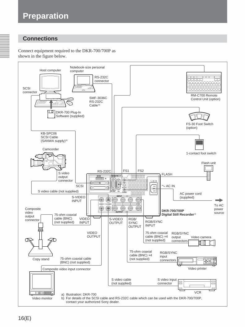
Connect equipment required to the DKR-700/700P asshown in the figure below.
VCR
Notebook-size personalcomputer
DKR-700 Plug-InSoftware (supplied)
Host computer
SCSI
SCSIconnector
RS-232Cconnector
KB-SPC06SCSI Cable(SANWA supply)b)
Camcorder
S videooutputconnector
S video cable (not supplied)
S-VIDEOINPUT
VIDEOINPUT
75-ohm coaxialcable (BNC)(not supplied)
Compositevideooutputconnector
75-ohm coaxial cable(BNC) (not supplied)
VIDEOOUTPUT
Composite video input connector
S video cable(not supplied)
S video inputconnector
Video printer
RGB/SYNCinputconnectors
75-ohm coaxialcable (BNC) ×4(not supplied)
RGB/SYNCINPUT
RGB/SYNCoutputconnectors
75-ohm coaxialcable (BNC) ×4(not supplied)
⁄ AC IN
AC power cord(supplied)
To ACpowersource
FLASHFS1 FS2
FS-30 Foot Switch(option)
1-contact foot switch
RM-C700 RemoteControl Unit (option)
DKR-700/700PDigital Still Recorder a)
RS-232C
SMF-3036CRS-232CCable b)
a) Illustration: DKR-700b) For details of the SCSI cable and RS-232C cable which can be used with the DKR-700/700P,
contact your authorized Sony dealer.
Video camera
Copy stand
Video monitor
⁄
SCSI REMOTE
INPUT
OUTPUT
FS2
EX-CTL
FLASHRS-232C FS1
VIDEO S-VIDEO R G B SYNC
Ú
…
AC IN
ID
S-VIDEOOUTPUT
RGB/SYNCOUTPUT
Flash unit

17(E)
Setting the DIP Switch
Set the DIP switch as required. (Set the SCSI-ID whenusing the SCSI interface.)
DIP switch
Setting and function of each switch
Timing settings for image capture
a) When switch 2 is set to “ON” and switch 3 to “OFF”,then even when the Flash item in the System Setup menuis set to On, the signal is not output from the FLASHconnector.
b) For more information about the timings 1 to 3, see“Timing for Capturing an Image Using a Foot Switch”(page 53(E)).
Switchnumber
Function Setting
1 SCSI connectortermination
To enable internalSCSI termination, setto ON.
2 Select the timing forcapturing an inputimage to memory usinga foot switch connectedto FS1 connector orFS2 connector.
See table below.
1 2 3 4 5 6 7 8ON
3 Select the timing forcapturing an inputimage to memory usinga foot switch connectedto FS1 connector orFS2 connector.
See table below.
4 reserved Set to OFF.
SCSI-ID Settings
MiniDiscs (MD Data Discs)
The DKR-700/700P uses data MiniDiscs (MMD-140MD Data Disc or equivalent).
Using MiniDiscs
• Do not open the protective shutter. Touching the discsurface directly may damage or dirty the surface,causing errors or making data unreadable.
• Do not expose the discs to direct sunlight, elevatedtemperatures, or dusty environments.
• There is no need to clean MiniDiscs.
5 reserved Set to OFF.
SCSI-ID
6 SCSI-ID See SCSI-ID Settingstable.
7
See SCSI-ID Settingstable.
8
See SCSI-ID Settingstable.
SCSI-ID
Switch 2 Switch 3 Timing for image capture tomemory
OFF OFF Third field after trigger signal is input.(Timing 1)b)
OFF ON Second field after trigger signal isinput. (Timing 2)b)
MD Protective
shutter
SCSI-ID 0 1 2 3 4 5 6 7
Switch 6 OFF OFF OFF OFF ON ON ON ON
Switch 7 OFF OFF ON ON OFF OFF ON ON
Switch 8 OFF ON OFF ON OFF ON OFF ON
ON a) OFF a) First field after trigger signal is input.(Timing 3)b)

18(E)
Protecting against accidental erasure
When more data is written to a previously recorded(full) disc, the older data may be lost. To guardagainst accidentally erasing important data, slide thewrite protect switch as shown in the illustration.
When a write-protected disc is inserted into the DKR-700/700P, recording operations will not be able to beperformed. In order to re-record a disc, return thewrite protect switch to its original position.
Labeling discs
Attach the supplied label to the disc, and make a noteof the disc’s contents. If the label is full, remove theold label and affix a new one. If new labels are affixedon top of old labels, or if the label is not aligned in itsproper position, malfunctions may occur, and thedisc drive may be damaged.
Preparation
Disc slot
EJECT button
BUSY indicator
POWER indicator
POWER switch Disc
Label (supplied with the disc)
Write-protect switch
Activating the DKR-700/700P andInserting/Removing Discs
Activating the DKR-700/700P
Turn the POWER switch on.
The POWER indicator lights and the DKR-700/700Pstarts.
After a few seconds, the SOURCE button lights, andthe keys on the front panel go into effect. The DKR-700/700P beeps if the “Beep” in the System Setupmenu is set to On.
For information on enabling the beep sound, see page46(E).
The POWER switch may be turned on or off while adisc is loaded.
Inserting a disc
Holding a disc with the arrow side up, insert it in theslot in the direction of the arrow.
Note
The orientation of a MiniDisc is different from that ofa floppy disk or MO disc.
When activating the DKR-700/700P, the BUSYindicator lights and the DKR-700/700P starts to checkthe data on the disc.

19(E)
When data check completes, the BUSY indicator goesout, and the DKR-700/700P beeps if the “Beep” in theSystem Setup menu is set to On.
If the disc is not initialized or initialized to a formatincompatible with the DKR-700/700PThe ALL ERASE/INIT button blinks (the message“Initialize” appears on the screen), and the DKR-700/700P stands-by for initialization. The button will stopblinking if it is left for about five seconds.
See “Initializing Discs” on this page for details.
Removing the disc
Press the EJECT button to eject the disc.
If the BUSY indicator is lit or blinking when you pressthe EJECT button, the disc is ejected after internalprocessing is completed.The Disc may be stored in the DKR-700/700P exceptwhen shipping the DKR-700/700P.
Initializing Discs
To record images on a disc with the DKR-700/700P,the disc must first be initialized to a format compatiblewith the DKR-700/700P.
Note
Initializing a disc erases all data in the disc. Check thedata recorded on the disc before beginning theoperation.
1 Insert a disc to be initialized into the DKR-700/700P and activate the DKR-700/700P (see page18(E)).
The ALL ERASE/INIT button blinks (the message“Initialize” appears on the screen).
2 While the ALL ERASE/INIT button is blinking,press it (or the ALL ERASE/INIT key). If the ALLERASE/INIT button/key is left for about fiveseconds, the button will stop blinking. The buttonwill start blinking by pressing it (or the ALLERASE/INIT key).
The ALL ERASE/INIT button lights, and discinitialization starts.After about 3 minutes, initialization completes (theALL ERASE/INIT button goes out).
Caution
During initialization the BUSY indicator is lit orblinking. At this point, be careful not to disconnectthe AC power cord from the outlet. If the power isdisconnected the disc could be damaged.
Setting the Clock
Before beginning to use the DKR-700/700P, set theinternal clock to the proper date and time.
The clock is set using the System Setup menu. For moreinformation, see page 46(E).
ALL ERASE/INIT button
ALL ERASE/INIT key

20(E)
Video outputconnector(s)
Video monitor
1
1
2
Checking the Setup/OperatingCondition of the DKR-700/700P
The DKR-700/700P’s setup information and operatingconditions can be displayed on the screen.
1 Connect a video monitor to the video outputconnector(s) on the rear panel of the DKR-700/700P (see page 16(E)) and activate the DKR-700/700P (see page 18(E)).
2 Press the DISP button/key.
Operation and setup information appears.
Note
If the “Live” item in the Capture/Rec Setup menuis set to Thru, operation and setup information willnot be displayed when the DISP button/key ispressed.
For more information on the Capture/Rec Setup menu,see page 41(E).
Preparation

21(E)
Items 2 to 8 change with the operating condition, asfollows:When playing: Information about the image
currently displayed on screen.Otherwise: Information about settings to be used for
the next image recorded. Item 3 is not displayed.At the item 4 position the number of images thedisc can still accommodate is displayed.
Changing the display formatDisplay of each item can be set on or off using theDisp Setup menu.
For more information on setting the display, see page 44(E).
RGB
No Input
Disc Name
ABCDEFG12345678
123456789012345 Fine
67
10:18:36
1996-01-01
2 Image number
5 Image quality
4 Time of recording
3 Date of recording
1 Operating modeSelected video input source (Video, S Video, or RGB) or operating condition (Capture or Play)If no video signal is input to the selected (using the menus) video input connector, the “NoInput” message will be displayed.
6 ID number
9 Message display area
8 Disc name7 Image name

22(E)
Recording Images
Preparing to Record
1
2
4
4 5
6
3Video camera, LaserDiscplayer, VCR, etc.
Videooutputconnector(s)
Video monitor
Video inputconnector(s)
Remote connector(s)
RM-C700, foot switch,flash unit, etc.
Illustration: DKR-700
1 Connect a video camera, LaserDisc player, VCR,etc. to the proper video input connector(s) on therear panel (see page 16(E)).
2 Connect a video monitor to the proper video outputconnector(s) on the rear panel (see page 16(E)).
3 Connect necessary auxiliary devices (RM-C700,foot switch, flash unit, etc.) to the proper remoteconnector(s) on the rear panel (see page 16(E)).
4 Power the DKR-700/700P (see page 18(E)).
Warning
When using the DKR-700P, make sure that thevoltage setting meets the voltage in the mains lineprior to the operation.
5 Insert a disc into the disc slot, after verifying thatthe disc has been properly initialized and that thewrite-protect switch is set to allow recording (seepage 18(E)).
6 Using the menus, make the following settings:
1) On the main menu, set “Input” appropriately forthe input video signal to be used (see page39(E)).
2) Set each item in the Source Setup menuappropriately for the input video signal to beused (see page 40(E)).
3) Set the necessary items on the System Setupmenu (see page 45(E)) and Capture/Rec Setupmenu (see page 41(E)) appropriately for theexternal devices to be used.
Adding ID numbers or image names to imagesWhen an image is recorded, its image numbers andrecording date are automatically recorded as well.When using the RM-C700, ID numbers and imagenames can also be recorded.
For information about ID number and image namerecording procedures, see “Image Data Management(Using the RM-C700)” on page 32(E).
23(E)
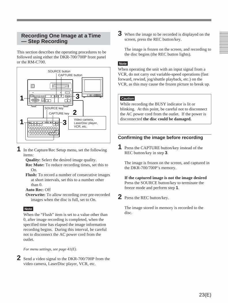
Recording One Image at a Time— Step Recording
This section describes the operating procedures to befollowed using either the DKR-700/700P front panelor the RM-C700.
1 In the Capture/Rec Setup menu, set the followingitems:Quality: Select the desired image quality.Rec Mute: To reduce recording times, set this to
On.Flush: To record a number of consecutive images
at short intervals, set this to a number otherthan 0.
Auto Rec: OffOverwrite: To allow recording over pre-recorded
images when the disc is full, set to On.
Note
When the “Flush” item is set to a value other than0, after image recording is completed, when thespecified time has elapsed the image informationrecording begins. During this interval, be carefulnot to disconnect the AC power cord from theoutlet.
For menu settings, see page 41(E).
2 Send a video signal to the DKR-700/700P from thevideo camera, LaserDisc player, VCR, etc.
1
2
3
1 3Video camera,LaserDisc player,VCR, etc.
CAPTURE key
SOURCE button
SOURCE key
CAPTURE button
3 When the image to be recorded is displayed on thescreen, press the REC button/key.
The image is frozen on the screen, and recording tothe disc begins (the REC button lights).
Note
When operating the unit with an input signal from aVCR, do not carry out variable-speed operations (fastforward, rewind, jog/shuttle playback, etc.) on theVCR, as this may cause the frozen picture to break up.
Caution
While recording the BUSY indicator is lit orblinking. At this point, be careful not to disconnectthe AC power cord from the outlet. If the power isdisconnected the disc could be damaged.
Confirming the image before recording
1 Press the CAPTURE button/key instead of theREC button/key in step 3.
The image is frozen on the screen, and captured inthe DKR-700/700P’s memory.
If the captured image is not the image desiredPress the SOURCE button/key to terminate thefreeze mode and perform step 1.
2 Press the REC button/key.
The image stored in memory is recorded to thedisc.

24(E)
1 3
21 3
Recording Images Automatically— Interval Recording
This section describes the operating procedures to befollowed using either the DKR-700/700P front panelor the RM-C700.
1 In the Capture/Rec Setup menu, set the followingitems:Quality: Select the desired image quality.Rec Mute: To reduce recording times, set this to
On.Flush: To record a number of consecutive images
at short intervals, set this to a number otherthan 0. (See “Note” in step 1 on page 23(E).)
Auto Rec: OffOverwrite: To allow recording over pre-recorded
images when the disc is full, set to On.
For menu settings, see page 41(E).
2 Send a video signal to the DKR-700/700P from thevideo camera, LaserDisc player, VCR, etc.
3 Press the REC button/key.
The image is frozen on the screen, and recording tothe disc begins (the AUTO indicator lights).
Note
When operating the unit with an input signal from aVCR, do not carry out variable-speed operations (fastforward, rewind, jog/shuttle playback, etc.) on theVCR, as this may cause the frozen picture to break up.
Video camera,LaserDisc player,VCR, etc.
SOURCE buttonPLAY button
SOURCE keyAUTO indicator
PLAY key
To stop recordingPress the SOURCE button/key or PLAY button/key.
Recording with a 1-Contact FootSwitch
One of the following three modes can be selected for a1-contact foot switch using the Capture/Rec Setupmenu:• Capture/Rec• Capture• Alternate
For menu settings, see page 41(E).
To record with the Capture/Rec mode
1 Perform steps 1 and 2 of “Recording One Image ata Time — Step Recording” (page 23(E)).
2 Press the foot switch when the image to berecorded is displayed on the screen.
The image is frozen on the screen, and recording todisc begins.
To record with the Capture mode
1 Perform steps 1 and 2 of “Recording One Image ata Time —Step Recording” (page 23(E)).
2 Press the foot switch when the image to berecorded is displayed on the screen.
The image is frozen on the screen, and captured inthe DKR-700/700P’s memory.
If the captured image is not the image desiredRepeat pressing the foot switch until the desiredimage is captured.
3 Press the REC button on the DKR-700/700P or theREC key on the RM-C700 .
The image stored in memory is recorded to thedisc.
Recording Images
25(E)
To record with the Alternate mode
1 Perform steps 1 and 2 of “Recording One Image ata Time — Step Recording” (page 23(E)).
2 Press the foot switch when the image to berecorded is displayed on the screen.
The image is frozen on the screen, and captured inthe DKR-700/700P’s memory.
3 Press the foot switch again.
The image stored in memory is recorded to thedisc.
Recording with the Optional FS-30 Foot Switch
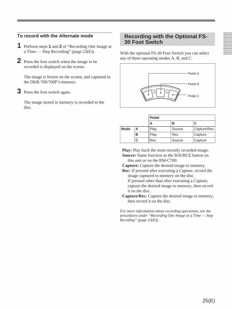
With the optional FS-30 Foot Switch you can selectany of three operating modes A, B, and C.
Play: Play back the most recently recorded image.Source: Same function as the SOURCE button on
this unit or on the RM-C700.Capture: Capture the desired image to memory.Rec: If pressed after executing a Capture, record the
image captured to memory on the disc.If pressed other than after executing a Capture,capture the desired image to memory, then recordit on the disc.
Capture/Rec: Capture the desired image to memory,then record it on the disc.
For more information about recording operations, see theprocedures under “Recording One Image at a Time — StepRecoding” (page 23(E)).
Pedal A
Pedal B
Pedal C
Pedal
A B C
Mode A Play Source Capture/Rec
B Play Rec Capture
C Rec Source Capture

26(E)
Playing or Searching for Images
Preparating to Playback or Search
2
3
3 4
1 5Video outputconnector(s)
Video monitor, videoprojector, etc.
Remote connector(s)RM-C700, etc.
1 Connect a video monitor, video projector, etc., tothe proper video output connector(s) on the rearpanel of the DKR-700/700P (see page 16(E)).
2 Connect necessary auxiliary devices (RM-C700,etc.) to the proper remote connector(s) on the rearpanel (see page 16(E)).
3 Power the DKR-700/700P (see page 18(E)).
Warning
When using the DKR-700P, make sure that thevoltage setting meets the voltage in the mains lineprior to the operation.
4 Insert a disc containing the images into the discslot (see page 18(E)).
5 1) In the main menu, set the “Video” appropriatelyfor the output video signal to be used (see page39(E)).
2) Set the necessary items in the System Setupmenu appropriately for the external devices tobe used (see page 45(E)).
Note
When operating the unit with an input signal from aVCR, do not carry out variable-speed operations (fastforward, rewind, jog/shuttle playback, etc.) on theVCR, as this may cause the playback picture to breakup.
Illustration: DKR-700

27(E)
Playing One Image at a Time— Step Playback
This section describes the operating procedures to befollowed using either the DKR-700/700P front panelor the RM-C700.
1 Make the following settings in the Play Setupmenu.“Mode” setting
When high-quality is demanded (mainimage display): Select Main.
When quick access is demanded (quickaccess image display): Select Quick.
If Auto is selected, the both quick access imageand main image are played back.On the DKR-700P, playing back a quick accessimage results in a black frame around the image.
Note
When playing back a main image (i.e. either Mainor Auto was selected in step 1), and when theimage to be displayed was stored uncompressed(by setting the “Quality” to Non Comp in theCapture & Rec Setup menu), it may take a fewmoments for the image to be displayed. (Duringthis time, no image will appear on the screen.)
1
2
1
3,4
3,42
“Play Mute” settingTo reduce the time until the image appears:
Set this to “On.” When the image ischanged the screen will go blank (i.e. be“muted”).
If you do not wish to blank (i.e. “mute”) theimage changes: Set this to “Off.” The timetaken for the image to appear will be longerthan when you use the “On” setting.
For menu settings, see page 43(E).
2 Press the PLAY button/key.
The DKR-700/700P starts playback (the PLAYbutton lights).If you selected “Quick” in step 1, the quick accessimage appears, and if you press the PLAY keyonce more during playback the main imageappears.
3 Press the [+] or [–] button/key.When the [+] button/key is pressed: An image
with larger-number is displayed.When the [–] button/key is pressed: An image
with smaller-number is displayed.
Note
If there are images already recorded on the discwith a different type of device, the image numbersmay in some cases not be consecutive.
4 Repeat step 3 to display other images.

28(E)
Playing or Searching for Images
2
1
2
1
Playing Images Automatically— Interval Playback
This section describes the operating procedures to befollowed using either the DKR-700/700P front panelor the RM-C700.
1 Set the following items in the Play Setup menu:Mode: See step 1 in the previous section
“Playing One Image at a Time — StepPlayback”.
Play Mute: See step 1 in the previous section,and make the appropriate setting. (“Mute”means “blank.”)
Auto PlayInterval: Set to the desired interval.Direction: Select the desired direction.
For menu settings, see page 43(E).
2 Press the AUTO PLAY button/key.
Images are displayed in the order and at theinterval specified in the menu settings.
Playing an Image by Its ImageNumber — Direct AccessPlayback (Using the RM-C700)
Direct access playback is performed using the RM-C700.
1 Set the “Mode” in the Play Setup menu to thedesired mode.
See step 1 in the section “Playing One Image at a Time— Step Playback” on page 27(E).
2 Enter the number of the desired image and pressthe PLAY button/key.
The selected image is displayed on the screen.
12

29(E)
Searching for an Image Usingthe Image Index
This section describes the operating procedures to befollowed using either the DKR-700/700P front panelor the RM-C700.
1 Press the IMAGE button/key.
The first page of the image index is displayed onthe screen.
1 2 3 4
6 7 8 9 10
11 12 13 14 15
16 17 18 19 20
21 22 23 24 25
5
1/ 4
2 Using the cursor buttons/keys, select the desiredimage.
1 2 3 4
6 7 8 9 10
11 12 13 14 15
16 17 18 19 20
21 22 23 24 25
5
1/ 4
If the desired image is not found in the firstpagePress the [+] or [–] button/key to change pages.
3 Press the PLAY button/key.
The selected image is displayed on the screen.
Searching for an Image UsingInformation Search List
Using the front panel
1 Press the LIST button.
The first page of the information search list isdisplayed on the screen.
[List]
1
2
3
4
5
[ ] Select [PLAY] Playµ
96-01-01
1/ 4
96-01-01
96-01-01
96-01-01
96-01-01
(Continued)
[+]/[–] buttons
[+]/[–] keys
1
2
2
31
3
Thumbnail
Imagenumber
Pagenumber
Cursor
[+]/[–] buttons2
31
Page number

30(E)
2 Using the ≥ or ˘ button, select the desiredimage.
[List]
1
2
3
4
5
[ ] Select [PLAY] Playµ
96-01-01
1/ 4
96-01-01
96-01-01
96-01-01
96-01-01
If the desired image is not foundPress the [+] or [–] button to change pages.
3 Press the PLAY button.
The selected image is displayed on the screen.
Using the RM-C700
1 Press the LIST key.
The List Search display appears on the screen.
[List Search]
Search: ID No
Keyword:
[ ] Select [ ] Set [EXEC]Executeµ
Mm
2 Using the or ≥ key, move the cursor (”) to the“Search” line.
3 Use the ¿ or ÷ key to select the type of search tobe performed.
The following selections are possible:Image No (image number), Title (image name),Date, and ID No (ID number).
4 Using the or ≥ key, move the cursor (”) to the“Keyword” line, and press the ¿ or ÷ key todisplay the cursor (_).
[List Search]
Search: ID No
Keyword:
[ ] Select [ ] Set [EXEC]Executeµ
Mm
5 Depending on the selection made in step 3, enterthe image number, image name, date, or IDnumber of the image to be searched for.
[List Search]
Search: ID No
Keyword: 123456
[ ] Select [ ] Set [EXEC]Executeµ
Mm
There is no need to enter all numbers or characters.Search is possible with several numbers orcharacters from the head of the ID number orimage name.
Playing or Searching for Images
[+]/[–] keys1
2,3,4,7
8
56
Cursor
Cursor

31(E)
6 Press the EXE key.
An information search list containing theinformation about the desired image is displayedon the screen.
[List]
3 ABCDEFGHIJKLMN
12345678901234
25 ABCDEFGHIJKLMN
12345679956
90 ABCDEFGHIJKLMN
123456805
95 ABCDEFGHIJKLMN
123456811
101 ABCDEFGHIJKLMN
123456923
[ ] Select [PLAY] Playµ
96-01-01
1/ 4
96-01-01
96-01-01
96-01-01
96-01-01
If the entry for the desired image is not on thelistPress the [+] or [–] key to change pages.
7 Using the or ≥ key, move the cursor to thenumber of the image to be displayed.
[List]
3 ABCDEFGHIJKLMN
12345678901234
25 ABCDEFGHIJKLMN
12345679956
90 ABCDEFGHIJKLMN
123456805
95 ABCDEFGHIJKLMN
123456811
101 ABCDEFGHIJKLMN
123456923
[ ] Select [PLAY] Playµ
96-01-01
1/ 4
96-01-01
96-01-01
96-01-01
96-01-01
8 Press the PLAY key.
The selected image is displayed on the screen.
Page number

32(E)
MENU IMAGE
ALLERASEERASEDISP +--
1 ! 2@ 3# 4$ 5% 6" 7&
8* 9(
0 ) -_
/ :
Q W E R T Y U I O P
SHIFT A S D F G H J K L
Z X C V B N M
=+ , .
SPC
DEL EXE
N n N n
RM-C700
LIST PLAY AUTOPLAY CAPTURE RECSOURCE
DISCNAME ID NO
…( X r
INIT
ID numbers and image names can be associated withimage data, and discs may be assigned names, usingthe optional RM-C700 Remote Control Unit.
Keys Used to Input ID Numbers, Image Names and Disc Names
The following keys are used for the input of IDnumbers, image names and disc names:
Image Data Management (Using the RM-C700)
ID NO (ID number) key: When thiskey is pressed, the ID numberinput display will appear on thescreen.
DEL (delete) key: Used todelete enteredcharacters andsymbols.
SHIFT key:• Holding down this key while pressing the DISC/
NAME key will enable the disc name function ofthat key.
• Holding it down while pressing a number/symbolkey will produce the symbol displayed on thatkey.
• Holding it down while pressing an alphabet keywill produce the capital letter displayed on thatkey.
DISC/NAME key: When this key is pressed, the imagename input display will appear on the screen. Ifpressed while holding down the SHIFT key, the discname input display will appear.
Number/symbol keys: Used to enter numbers andsymbols. To produce the symbol instead of thenumber, hold down the SHIFT key while pressingthe key for the desired symbol.
SPC (space) key:Used to enterspaces.
Alphabet keys: Used toenter letters. To entercapital letters, holddown the SHIFT keywhile pressing the keyfor the desired letter.

33(E)
The entered character is displayed, the cursormoves one position to the right.
5 Check the entered name, and press the EXE key ifit is correct.
Note
Once a disc name is set, it can not be erased.
Setting/Changing an ID Number
Setting an ID number
1 Press the ID NO key.
The ID number input display appears.
ID No:
Mode:Off
[ ] Select [ ] Setµ
Mm
2 Using the or ≥ key, move the cursor (”) to the“ID No” line.
3 Press the ¿ or ÷ key to display the cursor (_).
ID No:
Mode:Off
[ ] Select [ ] Setµ
Mm
(continued)
Setting/Changing the Disc Name
1 1) Connect a video monitor to the appropriateconnector(s) on the rear panel of the DKR-700/700P (see page 16(E)).
2) Insert the disc whose name is to be added ormodified into the DKR-700/700P, after makingsure that it is not write-protected (see page18(E)).
2 Press the DISC/NAME key while holding downthe SHIFT key.
The disc name input display appears.
Disc Name:
[ ] Select [EXE] Endµ
3 Press the ¿ or ÷ key to display the cursor andmove it to the position where characters are to beentered or changed.
Disc Name:
[ ] Select [EXEC] End
Mm
4 Enter the desired character (up to 15 characters).
Disc Name:Photo
[ ] Select [EXEC] End
Mm
Cursor
Cursor
34(E)
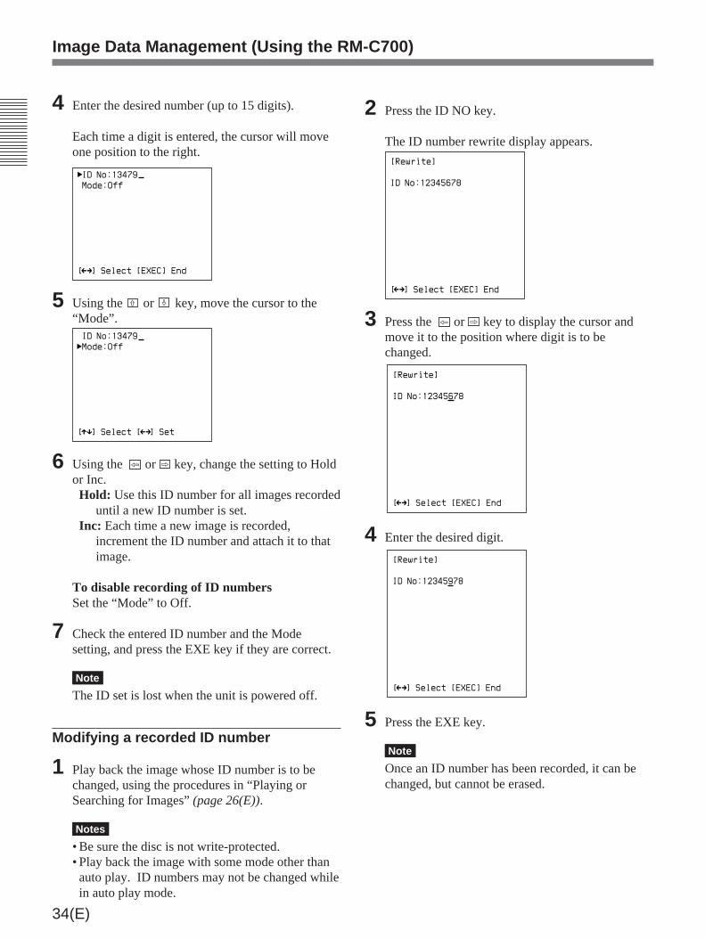
4 Enter the desired number (up to 15 digits).
Each time a digit is entered, the cursor will moveone position to the right.
ID No:13479
Mode:Off
[ ] Select [EXEC] End
Mm
5 Using the or ≥ key, move the cursor to the“Mode”. ID No:13479
Mode:Off
[ ] Select [ ] Setµ
Mm
6 Using the ¿ or ÷ key, change the setting to Holdor Inc.Hold: Use this ID number for all images recorded
until a new ID number is set.Inc: Each time a new image is recorded,
increment the ID number and attach it to thatimage.
To disable recording of ID numbersSet the “Mode” to Off.
7 Check the entered ID number and the Modesetting, and press the EXE key if they are correct.
Note
The ID set is lost when the unit is powered off.
Modifying a recorded ID number
1 Play back the image whose ID number is to bechanged, using the procedures in “Playing orSearching for Images” (page 26(E)).
Notes
• Be sure the disc is not write-protected.• Play back the image with some mode other thanauto play. ID numbers may not be changed whilein auto play mode.
2 Press the ID NO key.
The ID number rewrite display appears.
[Rewrite]
ID No:12345678
[ ] Select [EXEC] End
Mm
3 Press the ¿ or ÷ key to display the cursor andmove it to the position where digit is to bechanged.
[Rewrite]
ID No:12345678
[ ] Select [EXEC] End
Mm
4 Enter the desired digit.
[Rewrite]
ID No:12345978
[ ] Select [EXEC] End
Mm
5 Press the EXE key.
Note
Once an ID number has been recorded, it can bechanged, but cannot be erased.
Image Data Management (Using the RM-C700)

35(E)
Modifying a recorded image name
1 Play back the image whose image name is to bechanged, using the procedures in “Playing orSearching for Images” (page 26(E)).
Notes
• Be sure the disc is not write-protected.• Play back the image with some mode other thanauto play. Image names may not be changedwhile in auto play mode.
2 Press the DISC/NAME key.
The image name rewrite display appears.
[Rewrite]
[ ] Select [EXEC] End
Mm
Title:ABCDEF
3 Press the ¿ or ÷ key to display the cursor andmove it to the position where character is to bechanged.
[Rewrite]
[ ] Select [EXEC] End
Mm
Title:ABCDEF
4 Enter the desired character.
[Rewrite]
[ ] Select [EXEC] End
Mm
Title:ABCGEF
(Continued)
Setting/Changing an ImageName
Setting an image name
1 Press the DISC/NAME key.
The image name input display appears.Title:
[ ] Select [EXEC] End
Mm
2 Press the ¿ or ÷ key to display the cursor (_).
Title:
[ ] Select [EXEC] End
Mm
3 Enter the desired character (up to 15 characters).
Each time a character is entered, the cursor willmove one position to the right.
Title:ABCDE
[ ] Select [EXEC] End
Mm
4 Check the entered image name, and press the EXEkey if it is correct.
Note
The image name set is lost when the unit ispowered off.
Cursor

36(E)
5 Press the EXE key.
Note
Once an image name has been recorded, it can bechanged, but cannot be erased.
Image Data Management (Using the RM-C700)
37(E)
Deleting Images
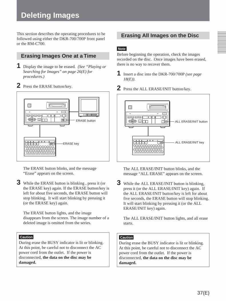
Erasing All Images on the Disc
Note
Before beginning the operation, check the imagesrecorded on the disc. Once images have been erased,there is no way to recover them.
1 Insert a disc into the DKR-700/700P (see page18(E)).
2 Press the ALL ERASE/INIT button/key.
The ALL ERASE/INIT button blinks, and themessage “ALL ERASE” appears on the screen.
3 While the ALL ERASE/INIT button is blinking,press it (or the ALL ERASE/INIT key) again. Ifthe ALL ERASE/INIT button/key is left for aboutfive seconds, the ERASE button will stop blinking.It will start blinking by pressing it (or the ALLERASE/INIT key) again.
The ALL ERASE/INIT button lights, and all erasestarts.
Caution
During erase the BUSY indicator is lit or blinking.At this point, be careful not to disconnect the ACpower cord from the outlet. If the power isdisconnected, the data on the disc may bedamaged.
This section describes the operating procedures to befollowed using either the DKR-700/700P front panelor the RM-C700.
Erasing Images One at a Time
1 Display the image to be erased. (See “Playing orSearching for Images” on page 26(E) forprocedures.)
2 Press the ERASE button/key.
The ERASE button blinks, and the message“Erase” appears on the screen.
3 While the ERASE button is blinking , press it (orthe ERASE key) again. If the ERASE button/key isleft for about five seconds, the ERASE button willstop blinking. It will start blinking by pressing it(or the ERASE key) again.
The ERASE button lights, and the imagedisappears from the screen. The image number of adeleted image is omitted from the series.
Caution
During erase the BUSY indicator is lit or blinking.At this point, be careful not to disconnect the ACpower cord from the outlet. If the power isdisconnected, the data on the disc may bedamaged.
ERASE button
ERASE key
ALL ERASE/INIT button
ALL ERASE/INIT key

38(E)
Menu Operations
The parameters dealing with unit operations andoperating environment are set using menus.
Menu Structure
The main menu and six setup menus are provided asshown below (the figure is for the DKR-700).
Main menu (see page 39(E))
Source Setup menu(see page 40(E))
Capture/Rec Setup menu(see page 41(E))
Play Setup menu(see page 43(E))
Disp Setup menu(see page 44(E))
System Setup menu(see page 45(E))
User Setup menu(see page 47(E))
[Source Setup]
Adjust R:
G:
B:
Hue:
Color:
Reset
Sync on Green:
B/W:
Skew Comp:
0
0
0
0
0
0
0
Off
Off
Off
H Position:
V Position:
[ ] Select [ ] Set [MENU] Menuµ Mm
[Capture/Rec Setup]
Quality:
Rec Mute:
Flush:
Capture Trig:
FS2 Mode:
Frame/Field:
Review:
Review Mode:
Fine
Off
0 sec
FS2
Capture/Rec
Frame
[ ] Select [ ] Set [MENU] Menuµ Mm
[Play Setup]
Mode: Auto
Play Mute: Off
Auto Play
Interval: 5 sec
Direction: Forward
Auto Start: Off
[ ] Select [ ] Set [MENU] Menuµ Mm
Live: EE
Off
Play
Auto Rec:
Overwrite:
Off
Off
[Disp Setup]
Mode:
Image No:
Quality:
Remain:
Disc Name:
Title:
ID No:
Date:
Time:
On
On
Off
Off
Off
Off
Off
Off
Off
[ ] Select [ ] Set [MENU] Menuµ Mm
[System Setup]
Flash:
Rec Tally:
RS-232C:
Baud Rate:
Disp Color:
Beep:
Key Click:
Rec End:
Off
High
RM-C700
9600
FS1 Mode: A
White
On
Off
Off
96-01-01
00:00
Date:
Time:
[ ] Select [ ] Set [MENU] Menuµ Mm
[User Setup]
Load: 1
Save: 1
[ ] Select [EXEC] Executeµ Mm
[Main]
Input: RGB
Video: Frame
Setup
Source
Capture/Rec
Play
Disp
System
User
[ ] Select [ ] Setµ Mm
”

39(E)
Buttons/Keys for Menu Operations
The buttons or keys shown below are used in menu operations.
Structure and Usage of the MainMenu
Press the MENU button/key.
The main menu appears.
[Main]
Input: RGB
Video: Frame
Setup
Source
Capture/Rec
Play
Disp
System
User
[ ] Select [ ] Setµ Mm
”
The details of each item are as follows:Input: Selects the type of input video signal.Video: Selects the display mode of output video
signal.Setup: Selects the type of setup to be performed, and
calls up the appropriate setup menu.
To remove the main menuPress the MENU button/key again.
To select the type of input video signal
Note
During recording, playback or displaying frozenimages (when the CAPTURE button is lit), the type ofinput video signal cannot be selected.
1 Press the or ≥ button/key to move the cursor tothe “Input” line.
[Main]
Input: RGB
Video: Frame
Setup
Source
Capture/Rec
Play
Disp
System
User
[ ] Select [ ] Setµ Mm
”
2 Press the ¿ or ÷ button/key to change the settingto the desired type.RGB: RGB signalS Video: S video signalVideo: Composite video signal
Cursor buttons:The ˘ and ≥ buttons areused to select the item to be set,and the ¿ and ÷ buttons areused to change the settings.
MEMU key
MENU button:• Turns the menu display on or off.• Switches the display from a setup
menu to the main menu.
EXEC button:• Switches the display from the main menu to a setup menu.• Confirms the date and time setting.• Perform reset of the gain, hue, and color level values.
Cursor keys
EXE key:• Switches the display from the main menu to a setup menu.• Confirms the date and time setting.• Perform reset of the gain, hue, and color level values.
Cursor

40(E)
User: Setup information for setting user data(registration/recall)
2 Press the EXEC button (or the EXE key on theRM-C700).
The selected setup menu appears.
Structure and Usage of theSource Setup Menu
Calling up the Source Setup menu
1 In the main menu, press the ˘ or ≥ button/key tomove the cursor to the “Source” line.
[Main]
Input: RGB
Video: Frame
Setup
Source
Capture/Rec
Play
Disp
System
User
[ ] Select [EXEC] Next Menuµ
2 Press the EXEC button (or the EXE key on theRM-C700).
The Source Setup menu appears.
[Source Setup]
Adjust R:
G:
B:
Hue:
Color:
Reset
Sync on Green:
B/W:
Skew Comp:
0
0
0
0
0
0
0
Off
Off
Off
H Position:
V Position:
[ ] Select [ ] Set [MENU] Menuµ Mm
a) This item is for the DKR-700 only.
To return to the main menuPress the MENU button/key.
To select the display mode of output video
Note
The following setting is valid for outputting freeze orplayback pictures.
1 Press the or ≥ button/key to move the cursor tothe “Video” line.
[Main]
Input: RGB
Video: Frame
Setup
Source
Capture/Rec
Play
Disp
System
User
[ ] Select [ ] Setµ Mm
”
2 Press the ¿ or ÷ button/key to change to thedesired setting.Frame: Frame displayField1/Field2: Field display. Switch the field by
setting to Field1 or Field2.
Calling up a setup menu
1 Move the cursor to the desired item using the ˘ or≥ button/key.
[Main]
Input: RGB
Video: Frame
Setup
Source
Capture/Rec
Play
Disp
System
User
[ ] Select [EXEC] Next Menuµ
The contents of the setup are as follows:Source: Setup information for the input signalCapture/Rec: Setup information for the frame
memory and disc recording operationsPlay: Setup information for playback operationsDisp: Setup information for the operating condition
displaySystem: Setup information regarding the DKR-700/
700P system
a)
a)
a)
Menu Operations
41(E)
To change the setup values
1 Move the cursor to the desired item using the ˘ or≥ button/key.
2 Change the setting using the ¿ or ÷ button/key.
The settings for each item are as follows:Adjust R/G/B: Used to adjust the gain for each
component of an RGB signal. Values can be setin the range from –127 to +127.
Adjust Hue (DKR-700 only): Used to adjust the hueof a composite or an S video signal. Values canbe set in the range from –127 to +127.
Adjust Color (DKR-700 only): Used to adjust thecolor level of a composite or an S video signal.
Reset: Used to reset the R, G, B, Hue, and Colorsettings to the values before changing.Resetting the valuesMove the cursor to the “Reset” line using the ˘or ≥ button/key and press the EXEC button (orthe EXE key on the RM-C700).
Sync on Green: When using an RGB input signalwhich has the Sync signal multiplexed with the Gsignal, set this to On.
Note
The setting of this item automatically becomes Onwhen the “Capture Trig” in the Capture/Rec Setupmenu is set to the Camera1 or Camera2.
B/W: Set to On to use a black and white input signal.
Note
When setting this item to On, set the item “DispColor” in the System Setup menu to White (see page42(E)).
Skew Comp (DKR-700 only): Set to On to use inputsignals containing jitter.
H Position: Specify the horizontal display positionon the screen when this unit is in source mode. (–10 to +10 points)
V Position: Specify the vertical display position onthe screen when this unit is in source mode. (–2 to+10 points for DKR-700, –5 to +10 points forDKR-700P)
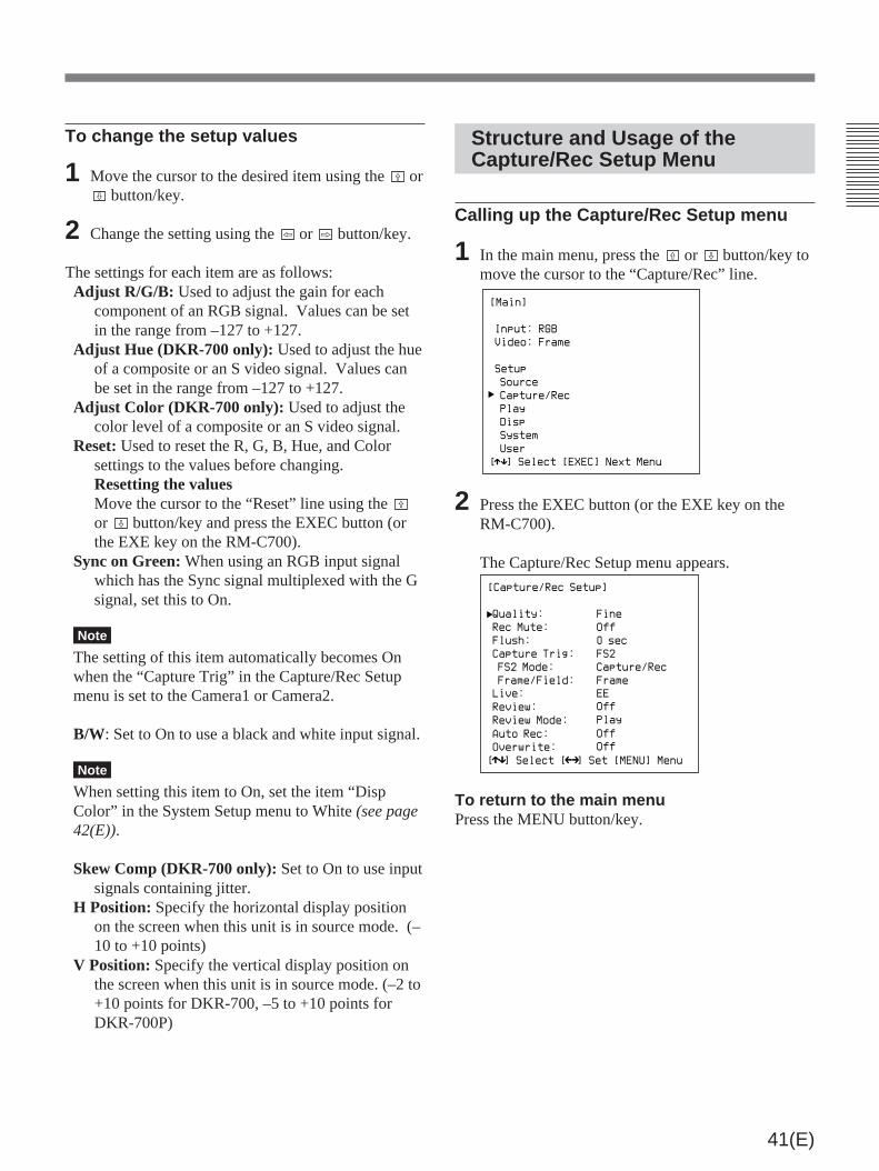
Structure and Usage of theCapture/Rec Setup Menu
Calling up the Capture/Rec Setup menu
1 In the main menu, press the ˘ or ≥ button/key tomove the cursor to the “Capture/Rec” line.
[Main]
Input: RGB
Video: Frame
Setup
Source
Capture/Rec
Play
Disp
System
User
[ ] Select [EXEC] Next Menuµ
2 Press the EXEC button (or the EXE key on theRM-C700).
The Capture/Rec Setup menu appears.
[Capture/Rec Setup]
Quality:
Rec Mute:
Flush:
Capture Trig:
FS2 Mode:
Frame/Field:
Review:
Review Mode:
Fine
Off
0 sec
FS2
Capture/Rec
Frame
[ ] Select [ ] Set [MENU] Menuµ Mm
Live: EE
Off
Play
Auto Rec:
Overwrite:
Off
Off
To return to the main menuPress the MENU button/key.

42(E)
To change the setup values
1 Move the cursor to the desired item using the ˘ or≥ button/key.
2 Change the setting using the ˘ or ≥ key.
The settings for each item are as follows:Quality: Used to select the quality of image
recording.Non Comp: Recording uncompressed imagesFine: Recording high-quality imagesNormal: Recording normal-quality imagesQuick 2: Quick recording normal-quality images
(recording the quick access images and searchimages only)
Quick 1: Quick recording (recording the quickaccess images and search images only)
Rec Mute: To reduce the recording time, set this to“On”. If this is set to “On”, the monitor is blanked(“muted”) during recording. If this is set to “Off”,the monitor is not blanked (“muted”) duringrecording.
Flush: Set the time delay after recording an imageuntil recording the image information. The settingvalues are 0, 13 seconds, 23 seconds, 33 seconds,1 minute, 3 minutes, 5 minutes, 10 minutes, andunlimited (∞).If you select a value other than 0, pressing thefollowing buttons or keys makes it possible tostart recording the image information.• EXEC button or EXE key• PLAY button/key (Playback starts after theimage information is recorded.)
• EJECT button (The disc is ejected after theimage information is recorded.)
• IMAGE button/key. (The image index appearson the screen after the image information isrecorded.)
Capture Trig: Used to select the method by whichrecording is controlled.FS2: Use a 1-contact foot switch (connect to the
FS2 connector). When this option is selected,also set the next item, “FS2 Mode”.
Camera1: Using a DXC-930 series/950 series(DXC-960/970MD for medical use) VideoCamera (RGB/SYNC connection), record inlong exposure mode. (The setting of “Sync onGreen” in the Source Setup menuautomatically becomes On.)
Note
Before selecting Camera1, put the DXC-930series/950 series (DXC-960/970MD for medicaluse) Video Camera into slow shutter mode. It isimpossible to control the DKR-700/700P with thecamera in a normal mode. If Camera1 should beselected during operation with the camera, turn offthe camera and change camera settings.
Camera2: Using a DXC-950 series (DXC-970MD for medical use) Video Camera (RGB/SYNC connection), record in the flashsynchronized mode. (The setting of “Sync onGreen” in the Source Setup menuautomatically becomes On.)
Note
When selecting Camera2, set the camera to flashmode.
Ext1/Ext2: Using some other connected externalequipment to control the capture trigger.
FS2 Mode: Selects the operation mode when using a1-contact foot switch.Capture/Rec: Begin recording an image as soon
as it is captured to memory.Capture: Just capture images to memory.Alternate: Capture an image to memory with the
first operation, and write it to disc on thesecond operation.
Frame/Field: To capture images in memory andrecord on the disc in frame units, select “Frame.”To capture images in memory and record on thedisc in field units, select “Field.” If using a field-transfer camera with synchronized flash, select“Field.”
..........................................................................................................................................................................................................1) EE (Electric to Electric) signal: A signal which is input to
the recording circuitry, but passes to the outputs havinggone through electrical circuits.
Menu Operations

43(E)
Structure and Usage of the PlaySetup Menu
Calling up the Play Setup menu
1 In the main menu, press the ˘ or ≥ button/key tomove the cursor to the “Play” line.
[Main]
Input: RGB
Video: Frame
Setup
Source
Capture/Rec
Play
Disp
System
User
[ ] Select [EXEC] Next Menuµ
2 Press the EXEC button (or the EXE key on theRM-C700).
The Play Setup menu appears.
[Play Setup]
Mode: Auto
Play Mute: Off
Auto Play
Interval: 5 sec
Direction: Forward
Auto Start: Off
[ ] Select [ ] Set [MENU] Menuµ Mm
a) This item is set to Main on the DKR-700P at shipping.
To return to the main menuPress the MENU button/key.
a)
Live: Selects whether the input video signal will beoutput as an “EE” (Electric to Electric)1) signal, orpassed directly to the outputs (as a simple loop-through “Thru” signal).If this item is set to either EE/Thru or Thru, thenext menu item will change from “Review” to“Timer.”
Note
While a menu is displayed on the screen, theoutput will be an EE signal even when either EE/Thru or Thru is selected. Remove the menu beforesetting this item.
EE: The output will always be an EE signal.EE/Thru: The output will be an EE signal except
while recording, when the output will switch toa Thru signal.
Thru: The output will be a Thru signal, except forwhen an image from the DKR-700/700Pinternal memory is being output (such as whenthe CAPTURE key is pressed).
Review/Timer: When the previous menu item“Live” is set to EE, this item will be “Review.”When “Live” is set to EE/Thru or Thru, this itemwill change to “Timer.”Review: To automatically review an image
immediately after it is recorded, set this item tothe desired playback time. The time may beset to 1 second, 3 seconds, 5 seconds, 7seconds, 10 seconds or Cont (continuous). Toturn off the review function, set this item toOff.
Timer: Select whether or not to display a memoryimage after it is recorded. When set to On, theimage stored in memory will be displayed forseveral seconds, and then the display willrevert to the input image. If set to Off, theinput image will be displayed immediately.When you set Rec Mute to “On”, Timerautomatically changes to “Off”.
Review Mode: Select the image to be reviewed.When set to “Capture”, the recorded image held inmemory is reviewed; when set to “Play”, theimage(s) on the disc is (are) reviewed.
Auto Rec: When performing automatic recording,this item sets the interval at which images are tobe recorded. The time may be set in a range from5 seconds to 60 minutes. To turn off the automaticrecording function, set this item to Off.
Overwrite: To allow recording over images alreadyrecorded on the disc, set to On.
a)
44(E)
To change the setup values
1 Move the cursor to the desired item using the ˘ or≥ button/key.
2 Change the setting using the ¿ or ÷ button/key.
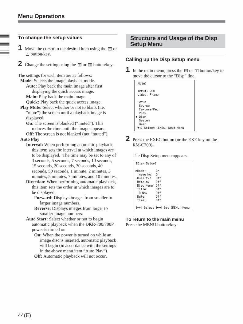
The settings for each item are as follows:Mode: Selects the image playback mode.
Auto: Play back the main image after firstdisplaying the quick access image.
Main: Play back the main image.Quick: Play back the quick access image.
Play Mute: Select whether or not to blank (i.e.“mute”) the screen until a playback image isdisplayed.On: The screen is blanked (“muted”). This
reduces the time until the image appears.Off: The screen is not blanked (not “muted”).
Auto PlayInterval: When performing automatic playback,
this item sets the interval at which images areto be displayed. The time may be set to any of3 seconds, 5 seconds, 7 seconds, 10 seconds,15 seconds, 20 seconds, 30 seconds, 40seconds, 50 seconds, 1 minute, 2 minutes, 3minutes, 5 minutes, 7 minutes, and 10 minutes.
Direction: When performing automatic playback,this item sets the order in which images are tobe displayed.Forward: Displays images from smaller to
larger image numbers.Reverse: Displays images from larger to
smaller image numbers.Auto Start: Select whether or not to begin
automatic playback when the DKR-700/700Ppower is turned on.On: When the power is turned on while an
image disc is inserted, automatic playbackwill begin (in accordance with the settingsin the above menu item “Auto Play”).
Off: Automatic playback will not occur.
Structure and Usage of the DispSetup Menu
Calling up the Disp Setup menu
1 In the main menu, press the ˘ or ≥ button/key tomove the cursor to the “Disp” line.
[Main]
Input: RGB
Video: Frame
Setup
Source
Capture/Rec
Play
Disp
System
User
[ ] Select [EXEC] Next Menuµ
2 Press the EXEC button (or the EXE key on theRM-C700).
The Disp Setup menu appears.
[Disp Setup]
Mode:
Image No:
Quality:
Remain:
Disc Name:
Title:
ID No:
Date:
Time:
On
On
Off
Off
Off
Off
Off
Off
Off
[ ] Select [ ] Set [MENU] Menuµ Mm
To return to the main menuPress the MENU button/key.
Menu Operations

45(E)
To change the setup values
1 Move the cursor to the desired item using the ˘ or≥ button/key.
2 Change the setting using the ¿ or ÷ button/key.
The settings for each item are as follows:Mode: To display the input signal type and the DKR-
700/700P’s operating condition, set to On.Image No: To display the image number of the next
image to be recorded or of the image currentlybeing played back, set to On.
Quality: To display the image quality setting, foreither record or playback, set to On.
Remain: To display the number of images that maybe recorded in the remaining disc space, set to On.
Disc Name: To display the disc name of the disccurrently in the DKR-700/700P, set to On.
Title: To display the name of the next image to berecorded or of the image currently being playedback, set to On.
ID No: To display the ID number of the next imageto be recorded or of the image currently beingplayed back, set to On.
Date: To display the recording date (y/m/d) of theimage currently being played back, set to On.
Time: To display the recording time (h/m/s) of theimage currently being played back, set to On.
Structure and Usage of theSystem Setup Menu
Calling up the System Setup menu
1 In the main menu, press the ˘ or ≥ button/key tomove the cursor to the “System” line.
[Main]
Input: RGB
Video: Frame
Setup
Source
Capture/Rec
Play
Disp
System
User
[ ] Select [EXEC] Next Menuµ
2 Press the EXEC button (or the EXE key on theRM-C700).
The System Setup menu appears.
[System Setup]
Flash:
Rec Tally:
RS-232C:
Baud Rate:
FS1 Mode:
Disp Color:
Beep:
Key Click:
Rec End:
Off
High
RM-C700
9600
A
White
On
Off
Off
96-01-01
00:00
Date:
Time:
[ ] Select [ ] Set [MENU] Menuµ Mm
To return to the main menuPress the MENU button/key.

46(E)
Setting date
1 Move the cursor (”) to the “Date” line using the˘ or ≥ button/key and press the ¿ or ÷ button/
key to display the cursor (_).
2 Move the cursor (_) to the item (day, month, oryear) to be set using the ¿ or ÷ button/key.
3 Using the ˘ or ≥ button/key, change the value ofthe selected item.
4 To change other items, repeat steps 2 and 3. Whenthe date is set correctly, go on to step 5.
5 Press the EXEC button (or the EXE key on theRM-C700).
The cursor (_) disappears.
Menu Operations
To change the setup values
1 Move the cursor to the desired item using the ˘ or≥ button/key.
2 Change the setting using the ¿ or ÷ button/key.
The settings for each item are as follows:Flash: To generate a trigger signal from the FLASH
connector, set this item to On.Rec Tally: Select the polarity of the Rec Tally signal
output from the FS2 connector. You can select“High” or “Low”.
RS-232C: Select the device to be connected to theRS-232C connector. (This item can be set only byfront panel operation.)RM-C700: The RM-C700 Remote Control Unit.Ext CPU: A computer. If this choice is selected,
the next item (“Baud Rate”) must also be set.Baud Rate: When controlling the DKR-700/700P
from a computer, the baud rate must be set tomatch that of the computer’s serial port.Allowable values are 1200, 2400, 4800, and 9600.
FS1 Mode: Selects the operation mode when usingan optional FS-30 Foot Switch. (See page 25(E).)
Disp Color: Used to set the colors of the displaycharacters. Available choices are white, red,green, yellow, blue, magenta, and cyan.
Beep: To cause the DKR-700/700P to beep uponerrors and the completion of operations, set this toOn. When set to On, the next items, “Key Click”and “Rec End”, may also be set.
Key Click: Setting this to On will cause the DKR-700/700P to emit a short click whenever one ofthe keys on the front panel or on the RM-C700 ispressed.
Rec End: Set this to “On” if you wish to sound abeeper when recording is completed.
Date: The date may be set into the internal clock.Time: The time may be set into the internal clock.
96-01-01
Cursor
96-01-01
96-02-01
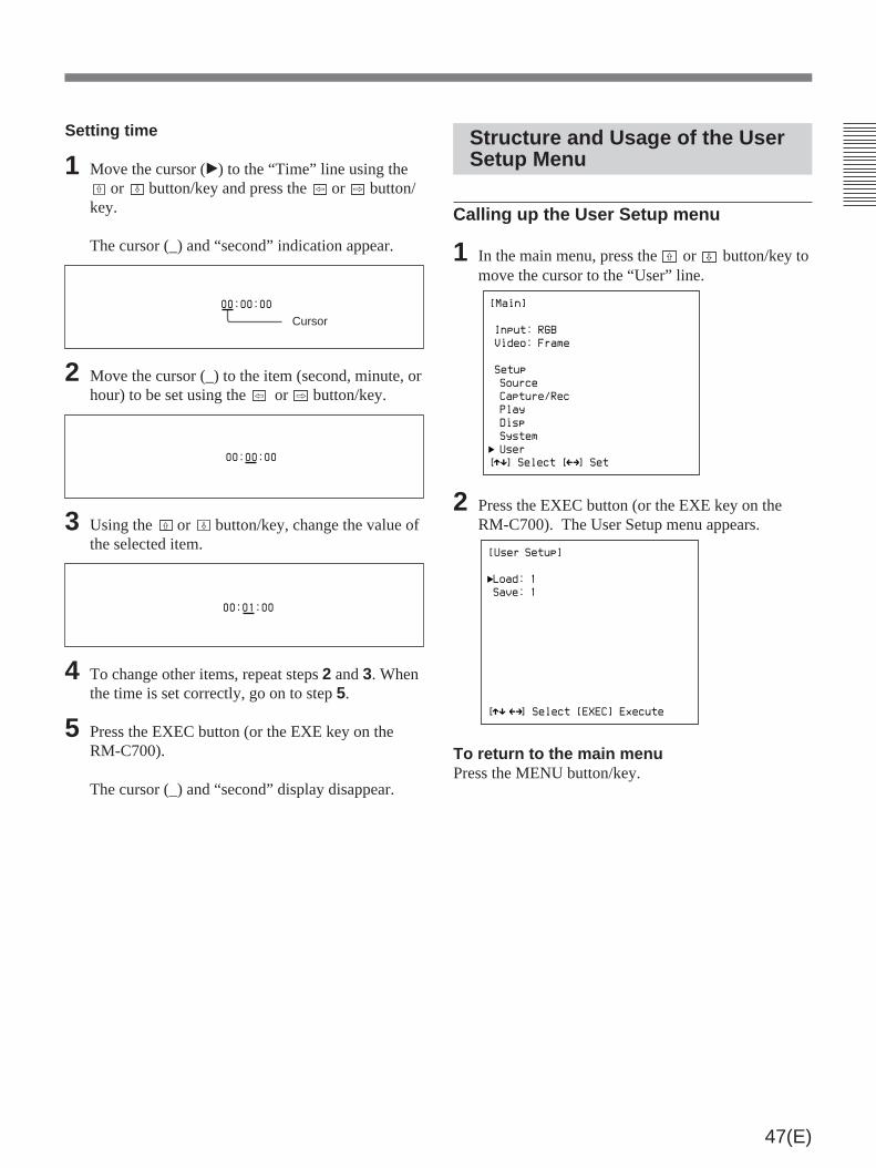
47(E)
Cursor00:00:00
00:00:00
00:01:00
Structure and Usage of the UserSetup Menu
Calling up the User Setup menu
1 In the main menu, press the ˘ or ≥ button/key tomove the cursor to the “User” line.
[Main]
Input: RGB
Video: Frame
Setup
Source
Capture/Rec
Play
Disp
System
User
[ ] Select [ ] Setµ Mm
2 Press the EXEC button (or the EXE key on theRM-C700). The User Setup menu appears.
[User Setup]
Load: 1
Save: 1
[ ] Select [EXEC] Executeµ Mm
To return to the main menuPress the MENU button/key.
Setting time
1 Move the cursor (”) to the “Time” line using the˘ or ≥ button/key and press the ¿ or ÷ button/
key.
The cursor (_) and “second” indication appear.
2 Move the cursor (_) to the item (second, minute, orhour) to be set using the ¿ or ÷ button/key.
3 Using the ˘ or ≥ button/key, change the value ofthe selected item.
4 To change other items, repeat steps 2 and 3. Whenthe time is set correctly, go on to step 5.
5 Press the EXEC button (or the EXE key on theRM-C700).
The cursor (_) and “second” display disappear.

48(E)
Menu Operations
Recalling user data
1 Call up the User Setup menu.
2 Press the or ≥ button/key to move the cursorto the “Load” line.
[User Setup]
Load: 1
Save: 1
[ ] Select [EXEC] Executeµ Mm
3 Press the ¿ or ÷ to select the number of thedesired user data.
The data whose number is highlighted in reversevideo can be recalled.
[User Setup]
Load: 2
Save: 1
[ ] Select [EXEC] Executeµ Mm
4 Press the EXEC button (or the EXE key on theRM-C700).
The current menu settings are replaced with therecalled user data, and the DKR-700/700P is insource mode.
Using the User Setup menu
The User Setup menu allows the settings for all menusto be registered as “user data,” and recalled as needed.
Registering user dataUp to three different sets of user data may be created,each identified with a number.
1 Set all menu items as desired, and then call up theUser Setup menu.
2 Press the or ≥ button/key to move the cursorto the “Save” line.
[User Setup]
Load: 1
Save: 1
[ ] Select [EXEC] Executeµ Mm
3 Press the the ¿ or ÷ to select 1, 2 or 3 as theregister number of the current menu settings.
A number highlighted in reverse video is alreadyused.
[User Setup]
Load: 1
Save: 2
[ ] Select [EXEC] Executeµ Mm
4 Press the EXEC button (or the EXE key on theRM-C700).
The current menu settings are registered as userdata.
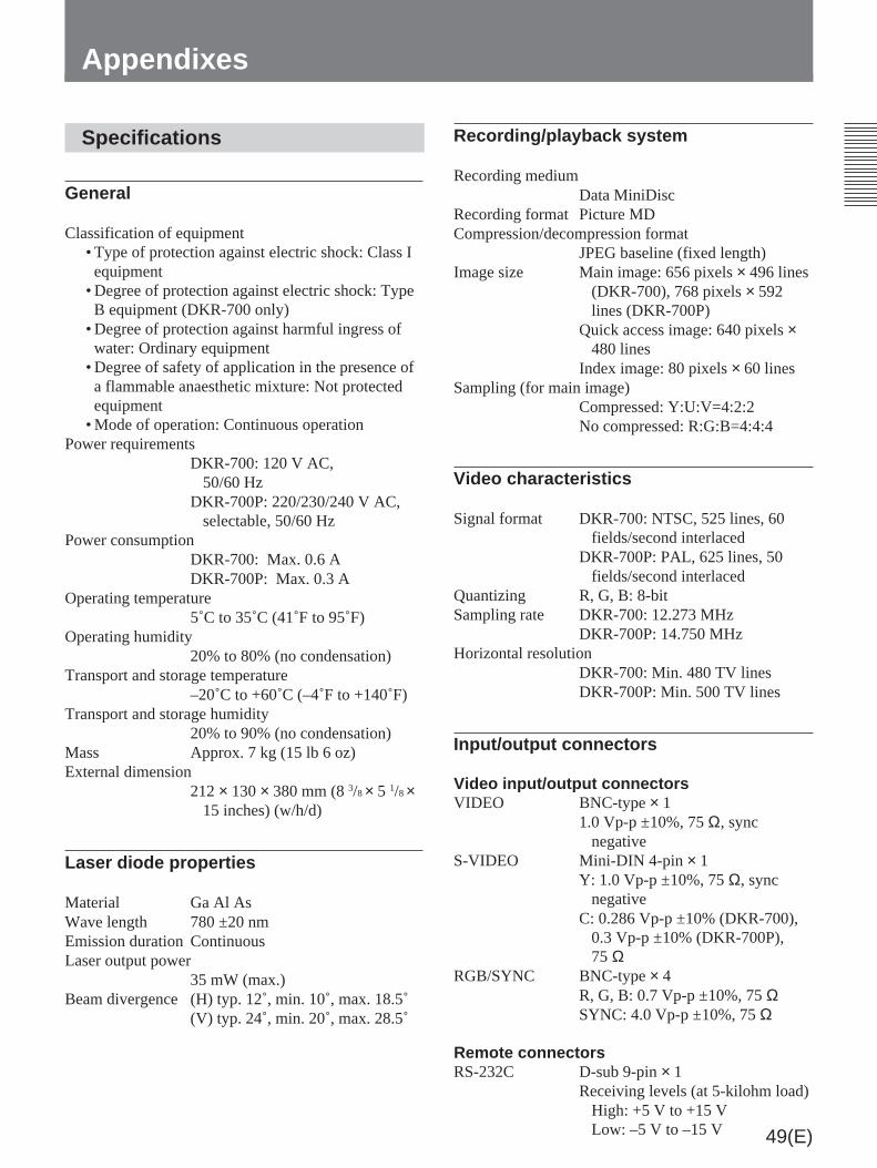
49(E)
Specifications
General
Classification of equipment• Type of protection against electric shock: Class Iequipment
• Degree of protection against electric shock: TypeB equipment (DKR-700 only)
• Degree of protection against harmful ingress ofwater: Ordinary equipment
• Degree of safety of application in the presence ofa flammable anaesthetic mixture: Not protectedequipment
• Mode of operation: Continuous operationPower requirements
DKR-700: 120 V AC,50/60 Hz
DKR-700P: 220/230/240 V AC,selectable, 50/60 Hz
Power consumptionDKR-700: Max. 0.6 ADKR-700P: Max. 0.3 A
Operating temperature5˚C to 35˚C (41˚F to 95˚F)
Operating humidity20% to 80% (no condensation)
Transport and storage temperature–20˚C to +60˚C (–4˚F to +140˚F)
Transport and storage humidity20% to 90% (no condensation)
Mass Approx. 7 kg (15 lb 6 oz)External dimension
212 × 130 × 380 mm (8 3/8 × 5 1/8 ×15 inches) (w/h/d)
Laser diode properties
Material Ga Al AsWave length 780 ±20 nmEmission duration ContinuousLaser output power
35 mW (max.)Beam divergence (H) typ. 12˚, min. 10˚, max. 18.5˚
(V) typ. 24˚, min. 20˚, max. 28.5˚
Appendixes
Recording/playback system
Recording mediumData MiniDisc
Recording format Picture MDCompression/decompression format
JPEG baseline (fixed length)Image size Main image: 656 pixels × 496 lines
(DKR-700), 768 pixels × 592lines (DKR-700P)
Quick access image: 640 pixels ×480 lines
Index image: 80 pixels × 60 linesSampling (for main image)
Compressed: Y:U:V=4:2:2No compressed: R:G:B=4:4:4
Video characteristics
Signal format DKR-700: NTSC, 525 lines, 60fields/second interlaced
DKR-700P: PAL, 625 lines, 50fields/second interlaced
Quantizing R, G, B: 8-bitSampling rate DKR-700: 12.273 MHz
DKR-700P: 14.750 MHzHorizontal resolution
DKR-700: Min. 480 TV linesDKR-700P: Min. 500 TV lines
Input/output connectors
Video input/output connectorsVIDEO BNC-type × 1
1.0 Vp-p ±10%, 75 Ω, syncnegative
S-VIDEO Mini-DIN 4-pin × 1Y: 1.0 Vp-p ±10%, 75 Ω, sync
negativeC: 0.286 Vp-p ±10% (DKR-700),
0.3 Vp-p ±10% (DKR-700P),75 Ω
RGB/SYNC BNC-type × 4R, G, B: 0.7 Vp-p ±10%, 75 ΩSYNC: 4.0 Vp-p ±10%, 75 Ω
Remote connectorsRS-232C D-sub 9-pin × 1
Receiving levels (at 5-kilohm load)High: +5 V to +15 VLow: –5 V to –15 V

50(E)
Appendixes
Transmitting levels (at 3-kilohmload)High: typ. +7.5 VLow: typ. –7.5 V
FS1 D-sub 9-pin ×1 (for an optional FS-30 Foot Switch connection)
FS2 Stereo minijack ×1 (for a 1-contactfoot switch connection)
39 kilohm pull-up (5 V DC)EX-CTL Minijack ×1 (for trigger output to
external equipment)Open collector output (max. 12 V
DC, 0.1 A)FLASH Minijack ×1 (for trigger output to
an optional flash unit)Output: 200 V DC (allowable
voltage), 0.3 ASCSI 50-pin, half-pitch×1
Output levelsHigh: 2.5 V to 5.25 VLow: 0 V to 0.4 V
Input levelsHigh: 2.0 V to 5.25 VLow: 0 V to 0.8 V
Accessories supplied
MMD-140 MD Data Disc (3)AC Power Cord (1)DKR-700 Plug-In Software (2)Instructions for Use (1)
Accessories not supplied
RM-C700 Remote Control UnitFS-30 Foot SwitchSMF-3036C RS-232C CableKB-SPC06 SCSI Cable (SANWA supply)
Recommended equipment
DXC-930 series/950 series (DXC-960/970MD formedical use) Color Video Camera
UP-1000 series/5500 series Color Video PrinterPVM series Color Video Monitor
Design and specifications are subject to changewithout notice.
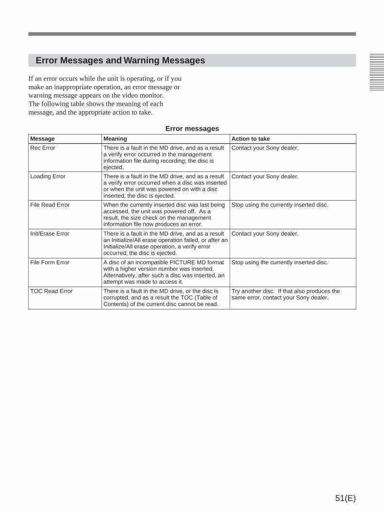
51(E)
Error Messages and Warning Messages
If an error occurs while the unit is operating, or if youmake an inappropriate operation, an error message orwarning message appears on the video monitor.The following table shows the meaning of eachmessage, and the appropriate action to take.
Message Meaning Action to take
Rec Error There is a fault in the MD drive, and as a resulta verify error occurred in the managementinformation file during recording; the disc isejected.
Contact your Sony dealer.
Loading Error There is a fault in the MD drive, and as a resulta verify error occurred when a disc was insertedor when the unit was powered on with a discinserted; the disc is ejected.
Contact your Sony dealer.
File Read Error When the currently inserted disc was last beingaccessed, the unit was powered off. As aresult, the size check on the managementinformation file now produces an error.
Stop using the currently inserted disc.
Init/Erase Error There is a fault in the MD drive, and as a resultan Initialize/All erase operation failed, or after anInitialize/All erase operation, a verify erroroccurred; the disc is ejected.
Contact your Sony dealer.
File Form Error A disc of an incompatible PICTURE MD formatwith a higher version number was inserted.Alternatively, after such a disc was inserted, anattempt was made to access it.
Stop using the currently inserted disc.
TOC Read Error There is a fault in the MD drive, or the disc iscorrupted, and as a result the TOC (Table ofContents) of the current disc cannot be read.
Try another disc. If that also produces thesame error, contact your Sony dealer.
Error messages

52(E)
Warning messagesMessage Meaning Actin to take
No Disc An attempt was made to record or play back,with no disc inserted.
Insert a disc.
Not Initialized An unformatted disc was inserted, or an attemptwas made to access it.
Press the ALL ERASE/INIT key to format thedisc.
Write Protect With a write-protected disc inserted, an attemptwas made to record or delete.
Remove the write protection from the disc.
No Image An attempt was made to play back or search,but the inserted disc has no images recorded onit.
Insert a disc on which images are recorded.
No Data An attempt was made to display the imageinformation list, but the inserted disc has noimage information recorded on it.
Insert a disc on which the image information isrecorded.
No More Rec An attempt was made to record, but the inserteddisc has no remaining recording capacity.
Make sure the disc has sufficient recordingcapacity before recording.
Batt Empty The unit was powered on with the lithium batteryexhausted.
Contact your Sony dealer.
No Info. Area The inserted disc has been recorded on adifferent system, and there is no space to writethe disc name, file names, ID numbers, imagenames, and other items; an attempt was madeto enter or amend this information.
Do not enter or amend the information.
Erase Inhibit An attempt was made to erase or overwrite animage which was written on a different type ofunit, and which has erase-inhibit set.
Do not erase or overwrite the image.
Data Not Save When executing Load in the User Setup menu,you specified a data number for which the datahas not been entered.
Specify a data number for which the data hasbeen entered.
Not Source Mode You pressed the All Erase key with the unit notin the source mode.
Press the Source key to put the unit in thesource mode before pressing the All Erase key.
Not Play Mode You pressed the Erase key with the unit not inthe play mode.
Press the Play key to put the unit in the playmode before pressing the Erase key.
Audio Disc The disc is ejected, because it is an audioMiniDisc.
Insert a data MiniDisc.
Not MD Data Disc The disc is ejected, because it is neither a dataMiniDisc nor an audio MiniDisc.
Insert a data MiniDisc.
Appendixes

53(E)
The DKR-700/700P is in still mode, and does not recognizeinput when connected to the DXC-930 series/950 series(DXC-960/970MD for medical use) Video Camera.
• The input signal may be non-interlaced. Use an interlacedinput signal.
• When using the DKR-700, the input signal may have ahorizontal frequency of 15.75 MHz. Set the “Skew Comp”setting to Off in the Source Setup menu (page 40(E)).
Cause/Remedy
The POWER switch is turned on, but the DKR-700/700P doesnot power up.
Check to see that the power source is properly connected(page 16(E)).
The REC button is pressed but recording does not occur. • The disc may be write-protected. Remove the writeprotection (page 18(E)).
• The disc may be full (and the menu set to disallowoverwriting). Use a new, initialized disc (page 19(E)), orchange the Capture/Rec Setup menu setting to allowoverwriting (page 41(E)).
• The disc may not be initialized to the proper format. Initializethe disc (page 19(E)).
The upper portion of the screen oscillates horizontally.
The menu may be set to “Camera1”, but the camera is not inslow shutter mode. Stop sync input from the camera, orpower off the camera and change the Capture/Rec Setupmenu setting (page 41(E)) or camera settings.
Symptom
Troubleshooting
Should a problem occur with the operation of theDKR-700/700P, check the following list beforecontacting a Sony representative, and see if theremedies given solve the problem.

54(E)
Timing for Capturing an ImageUsing a Foot Switch
If you capture an image using a foot switch, use theDIP switch on the rear panel of the DKR-700/700P toset capture timing. (See page 17(E).)The following figures show which frame or field iscaptured on the selected timing.
Capturing images in frame unitsSelect “Frame” for “ Frame/Field” in the Capture/RecSetup menu. (See page 41(E).)
ab
ab
ab
1 2 3 4 5
1 2 3 4 5
1 2 3 4 5
Timing 1 (Switch 2: OFF, Switch 3: OFF)
Triggersignal
Input videosignals
Frame captured into memory
Timing 2 (Switch 2: OFF, Switch 3: ON)
Triggersignal
Input videosignals
Frame captured into memory
Timing 3 (Switch 2: ON, Switch 3: OFF)
Triggersignal
Input videosignals
Frame captured into memory
a: 699 or 731 µs (DKR-700)672 or 704 µs (DKR-700P)
b: 16.7 ms (DKR-700)20.0 ms (DKR-700P)
Capturing images in field unitsSelect “Field” for “ Frame/Field” in the Capture/RecSetup menu. (See page 41(E).)
ab
ab
ab
1 2 3 4 5
1 2 3 4 5
1 2 3 4 5
Timing 1 (Switch 2: OFF, Switch 3: OFF)
Triggersignal
Input videosignals
Field captured into memory
Timing 2 (Switch 2: OFF, Switch 3: ON)
Triggersignal
Input videosignals
Field captured into memory
Timing 3 (Switch 2: ON, Switch 3: OFF)
Triggersignal
Input videosignals
Field captured into memory
a: 699 or 731 µs (DKR-700)672 or 704 µs (DKR-700P)
b: 16.7 ms (DKR-700)20.0 ms (DKR-700P)
Appendixes

1(F)
Français
AVERTISSEMENT
Afin d’éviter tout risque d’incendie ou d’électrocution, ne pasexposer cet appareil à la pluie ou à l’humidité.
Pour éviter tout risque de décharge électrique, ne pas ouvrirle boîtier. Confiez l’entretien uniquement à un personnelqualifié.
Ce symbole signale un équipement de type Bselon la classification de la norme médicaleinternationale IEC Publication 601-1 Sécuritémédicale d’équipements électriques(DKR-700 seulement).
Ce symbole indique la borne équipotentielle quimet les différentes parties du système au mêmepotentiel (DKR-700P seulement).
Pour DKR-700P
L’étiquette ci-dessous est apposée sur le dessus del’appareil.
L’étiquette ci-dessous est collée dans l’appareil.
4-627-743-01
DANGERINVISIBLE LASER RADIATION WHEN OPEN.
AVOID DIRECT EXPOSURE TO BEAM.
VORSICHTUNSICHTBARE LASERSTRAHLUNG, WENN ABDECKUNG
GEÖFFNET. NICHT DEM STRAHL AUSSETZEN.
PILE AU LITHIUMDoit être remplacée par un technicien compétent. Risqued’explosion en cas de manipulation incorrecte.
Précautions/instructions importantes pour uneutilisation dans des environnements médicaux
1. Tous les équipements raccordés à cet appareil doiventêtre agréés conformément aux normes IEC601-1,IEC950, IEC65 ou aux autres normes IEC/ISOapplicables à ces équipments.
2. Si cet appareil est utilisé conjointement avec d’autresappareils à proximité du patient*, l’équipement doit êtrealimenté par un transformateur d’isolement ou raccordévia une borne de mise à la terre supplémentaire pourrelier le système à la masse jusqu’à ce qu’il soit agrééconformément à la norme IEC601-1.
* Proximité du patientR1,
5m
3. Le courant de fuite peut augmenter si raccordé à d’autreséquipements.
4. Cet appareil génère, utilise et peut émettre desradiofréquences. S’il n’est pas installé et utiliséconformément au mode d’emploi, il peut provoquer desinterférences avec d’autres appareils. Si cet appareilgénère des interférences (ce que l’on peut facilementcontrôler en débranchant le cordon d’alimentation del’appareil), appliquez l’une des mesures suivantes:Installez cet appareil à un autre endroit en tenant comptede l’autre équipement. Branchez cet appareil et l’autreéquipement sur des circuits d’alimentationn différents.Consultez votre revendeur.

2(F)
Table des matières
Aperçu ...................................................................3(F)Caractéristiques ............................................... 3(F)Exemple d’utilisation ...................................... 4(F)Précautions pour l’utilisation .......................... 6(F)
Emplacement et fonction des organes etcommandes .....................................................7(F)DKR-700/700P ................................................ 7(F)Unité de télécommande RM-C700
(en option) ........................................... 13(F)
Préparatifs ...........................................................15(F)Connexions .................................................... 15(F)Réglage du commutateur DIP ....................... 16(F)MiniDisc (disque de données MD) ............... 17(F)Activation du DKR-700/700P et
insertion/retrait d’un disque ................ 18(F)Initialisation d’un disque ............................... 18(F)Réglage de l’horloge ..................................... 19(F)Contrôle de l’état d’implantation/exploitation
du DKR-700/700P............................... 19(F)
Enregistrement d’images ...................................21(F)Préparatifs pour l’enregistrement .................. 21(F)Enregistrement d’images une à une
(pas à pas)............................................ 22(F)Enregistrement automatique d’images
à intervalle ........................................... 23(F)Enregistrement avec un commutateur au
pied à 1 contact ................................... 23(F)Enregistrement avec un commutateur au
pied FS-30 en option ........................... 24(F)
Reproduction ou recherche d’images ...............25(F)Préparatifs pour la reproduction ou la
recherche ............................................. 25(F)Reproduction des images une à une
(pas à pas)............................................ 26(F)Reproduction automatique d’images
à intervalle ........................................... 27(F)Reproduction d’une image avec son numéro
d’image — Reproduction par accèsdirect (avec la RM-C700) ................... 27(F)
Recherche d’une image avec l’indexd’images .............................................. 28(F)
Recherche d’une image avec la liste derecherche d’informations .................... 28(F)
Gestion des données d’image(avec la RM-C700) .......................................31(F)Touches utilisées pour entrer les numéros ID,
noms d’image et noms de disque ........ 31(F)Pose/modification du nom du disque ............ 32(F)Pose/modification d’un numéro ID ............... 32(F)Pose/modification d’un nom d’image ........... 34(F)
Effacement d’images ..........................................36(F)Effacement des images une à une.................. 36(F)Effacement de toutes les images sur le
disque .................................................. 36(F)
Opérations de menu ...........................................37(F)Structure de menus ........................................ 37(F)Touches pour les opérations de menus .......... 38(F)Structure et emploi du menu principal .......... 38(F)Structure et emploi du menu Source Setup ... 39(F)Structure et emploi du menu Capture/
Rec Setup ............................................ 40(F)Structure et emploi du menu Play Setup ....... 42(F)Structure et emploi du menu Disp Setup ....... 43(F)Structure et emploi du menu System
Setup.................................................... 44(F)Structure et emploi du menu User Setup ....... 46(F)
Appendices ..........................................................48(F)Spécifications ................................................ 48(F)Messages d’erreur et d’avertissement ........... 50(F)Dépannage ..................................................... 52(F)Temporisation pour la capture d’une image
avec le commutateur au pied ............... 53(F)

3(F)
Aperçu
L’enregistreur d’images fixes numérique DKR-700/700P est destiné à l’enregistrement d’images fixes surMiniDisc (disque de données MD) et à leur archivagepour une reproduction ultérieure.
Caractéristiques
Le MiniDisc comme supportd’enregistrement
Le DKR-700/700P enregistre des images sur unMiniDisc (disque de données MD MMD-140 ouéquivalent: 140 Mo) conforme au format d’image MDSony. Ce support d’enregistrement magnéto-optiqueoffre non seulement un degré de permanence et defiabilité élevé, mais réduit également le coût destockage des images fixes parce qu’il permetl’enregistrement d’un maximum de 1.000 images surun disque.
Enregistrement avec compressionnumérique
L’emploi des dernières techniques numériques permetau DKR-700/700P de fournir une qualité d’imagesupérieure à 480 lignes de résolution horizontale. Et laméthode de compression JPEG et le format TIFF pourimages non-comprimées largement utilisés d’examinerles images à l’aide de logiciels disponibles dans lecommerce.
Qualité d’image sélectionnable
Pendant l’enregistrement, il est possible de choisirparmi cinq modes de qualité d’image (non-comprimé,fine, normal, rapide 2 et rapide 1). Cela rend cetappareil utilisable pour une large gammed’applications allant du domaine médical, qui exigeune haute qualité d’image, aux systèmes d’archivage,qui mettent l’accent sur le stockage de grands nombresd’images dont la recherche doit être rapide.
Enregistrement simultané d’informationsd’image
A l’enregistrement d’une image, la date (année, mois,jour, heure, minutes et secondes) et le numéro d’imagesont automatiquement enregistrés ou remis à jour. Laconnexion à une Unité de télécommande RM-C700 enoption ou à un ordinateur permet d’ajouter un numérod’identification (ID) d’image (15 chiffres max.) et unnom d’image (15 caractères alphanumériques max.)
Haute fonctionnalité de la recherche
Le DKR-700/700P permet de trouver rapidementl’image souhaitée. La recherche peut se faire parinformation sur l’image, par exemple numéro d’image,numéro ID, nom d’image ou date; une image peutaussi être localisée par index d’image (25 imagesconcises par index).
Implantation par menus
Les menus permettent les sélections de base, telles queconnecteurs d’entrée/sortie vidéo et qualitéd’enregistrement des images, ainsi que l’implantationdes modes d’enregistrement et de reproduction, d’état/implantation de l’affichage d’informations et ducontrôle du système.
Des connecteurs d’entrée/sortie vidéovariés
Le DKR-700/700P est doté de connecteurs d’entrée/sortie RGB, composites et S-video. Il permet lasélection d’une grande variété de sources d’entréeallant des sources ordinaires, telles que caméras vidéoet magnétoscopes aux lecteurs de LaserDisc etéquipements médicaux de création d’image. Il peut seraccorder à des dispositifs de sortie, tels que moniteursvidéo, projecteurs vidéo et imprimantes vidéo.

4(F)
Fonctionnalité du contrôle extérieur
Le DKR-700/700P est pourvu d’un connecteurd’interface RS-232C et d’un connecteur d’interfaceSCSI. Outre l’Unité de télécommande RM-C700 ou unordinateur, un commutateur au pied FS-30 à 3 contacts(en option) ou un commutateur au pied à 1 contactpeut être connecté pour le contrôle extérieur del’appareil.
Sélection des modes d’enregistrement etde reproduction selon les applications
Les images peuvent être enregistrées et reproduites uneà une (enregistrement/reproduction pas à pas) ouenregistrées et reproduites dans l’ordre(enregistrement/reproduction à intervalle).
Aperçu
Synchronisation à un dispositif d’image
Le DKR-700/700P peut produire un signal dedéclenchement de flash à l’enregistrement d’uneimage, et l’acquisition d’images peut donc se faire ensynchronisation avec un flash. En combinaison avecune caméra vidéo de série DXC-950 (DXC-970MD àusage médical) Sony, l’emploi de l’obturateurélectronique à ouverture lente permet l’enregistrementd’image claires et nettes, même dans le cas d’imagesfaiblement éclairées, comme celles de microscopes àfluorescence.
Exemple d’utilisation
Système d’archivage d’images pour des applications de mesure médicale ou industrielle
Le DKR-700/700P peut être couplé à des instrumentsmédicaux ou des équipements de mesure d’usine pourconstituer un système d’archivage d’images. L’emploidu logiciel Plug-In DKR-700 fourni (fonctionnant sur
Microsoft Windows1) ou MacOS2)) permet detransférer des données d’image vers un ordinateurraccordé au DKR-700/700P via une interface SCSI.
Moniteur vidéo
Microscope DKR-700/700P
SCSI
Unité de télécommandeRM-C700 (en option)
Ordinateur
SCSI
Imprimante vidéo sérieUP-5500
Caméra vidéo
1) “Windows” est une marque de fabrique de MicrosoftCorporation.
.........................................................................................................................................................................................................
Logiciel Plug-In DKR-700(fourni)
2) Le logiciel Plug-In peut ne pas fonctionner correctementsur le PowerBook.

5(F)
Système de contrôle photo
Système de traitement d’image informatisé
L’emploi du logiciel Plug-In DKR-700 fourni(fonctionnant sur Microsoft Windows ou MacOS1))permet d’échanger des données d’image avec unordinateur raccordé au DKR-700/700P via une
interface SCSI.Les images peuvent être transférées de l’appareil versun ordinateur pour traitement et utilisation pour laproduction d’images fixes infographiques.
Statif de copie
Moniteur vidéo
DKR700/700P
SCSI
Ordinateur
Logiciel Plug-In DKR-700 (fourni)
Unité detélécommandeRM-C700 (enoption)
Lors de la prise de photographies avec un appareil àfilm, ces images peuvent être capturées simultanémentavec la caméra vidéo de série DXC-950 (DXC-970MDà usage médical) et stockées dans le DKR-700/700Ppour permettre leur contrôle avant le développement,l’impression ou l’agrandissement des photos. Uneimage peut être capturée par enregistrement
automatique basé sur la temporisation d’un signal dedéclenchement de la vidéo caméra, ou la temporisationde capture peut être contrôlée par un signal de flashproduit par le DKR-700/700P. Outre le contrôle dansun studio photo, ce système peut également s’utiliserpour la photographie de mesure industrielle oumédicale.
Eclair
Flash
Flash photoasservi
Signal dedéclenchement
Caméra vidéo
Appareil à film
Moniteur vidéo
DKR-700/700P
Imprimante vidéo sérieUP-1000
Caméra vidéo
.........................................................................................................................................................................................................
1) Le logiciel Plug-In peut ne pas fonctionner correctementsur le PowerBook.

6(F)
Précautions pour l’utilisation
Emplacements de fonctionnement et destockageEviter de faire fonctionner ou de stocker l’appareildans les endroits suivants.• Emplacement soumis à des températures extrêmes(gamme de températures de fonctionnement: 5 à 35˚C(41 à 95˚F))
• Emplacement en plein soleil pendant longtemps, ouprès d’un appareil de chauffage (Noter que latempérature dépasse 50˚C (122˚F) dans une voituregarée en plein soleil fenêtres closes en été.)
• Endroits humides ou poussiéreux• Emplacements soumis à de fortes vibrations• Emplacement proche d’un appareil à émissionsélectromagnétiques fortes
• Emplacement près d’une station d’émissionproduisant des ondes hertziennes puissantes.
Faire fonctionner l’appareil à l’horizontaleCet appareil est prévu pour fonctionner en positionhorizontale. Ne pas l’opérer sur le côté, ni trop incliné(plus de 20˚).
Eviter les impacts violentsLa chute de l’appareil, ou tout autre choc violent, peutprovoquer un mauvais fonctionnement.
Ne pas obstruer les ouvertures de ventilationPour éviter la surchauffe, ne pas obstruer lesouvertures de ventilation par exemple en enveloppantl’appareil d’un tissu pendant le fonctionnement.
Contrôle périodiqueLe contrôle périodique est inutile.
NettoyageSi le coffret ou le panneau sont sales, les essuyerdoucement avec un chiffon doux et sec. En cas desaleté rebelle, utiliser un chiffon humidifié dedétergent neutre pour éliminer la saleté, puis essuyeravec un chiffon sec. L’emploi d’alcool, diluants,insecticides, etc. ou autres solvants volatils peutdéformer le coffret ou abîmer la finition.
Transport• Toujours retirer le disque avant le transport del’appareil.
• Emballer l’appareil dans son carton d’origine ou unemballage équivalent, et prendre garde aux chocsviolents pendant le transit.
Aperçu

7(F)
DIGITAL STILL RECORDER
POWER
POWER BUSY EJECT
MENU DISP IMAGE LIST
SEARCH
PLAY AUTOPLAY SOURCE CAPTURE REC
ERASE ALLERASE
INIT
+EXEC
…(
6
X rAUTO
----
DKR-700/700P
Alimentation et enregistrement/effacement des données (panneau avant)
1 Interrupteur d’alimentation (POWER u) ettémoinUne pression met l’appareil sous tension, et uneseconde hors tension. Le témoin est allumé quandl’appareil est sous tension. Si le témoin BUSY estallumé ou clignotant à la pression de l’interrupteurPOWER pour mettre l’appareil hors tension, l’appareilse mettra hors tension après l’achèvement dutraitement interne.
2 Logement de disquePour l’insertion des disques.
3 Témoin d’occupation (BUSY)Est allumé ou clignote lorsqu’une opération esteffectuée sur le disque, ou quand il reste des donnéesdans la mémoire du DKR-700/700P. Quand ce témoinest allumé, toutes les touches, sauf la touche EJECT 4sont inopérantes.
Attention
Ne pas déconnecter le cordon d’alimentation secteurde la prise alors que le témoin BUSY est allumé ouclignotant. En cas de mise hors tension alors qu’uneopération est faite sur le disque, les donnéesstockées sur le disque pourront être perdues ouendommagées.
4 Touche d’éjection (EJECT 6)Appuyer pour éjecter le disque.
5 Touche et témoin d’enregistrement (REC r)Le témoin s’allume à la pression de la touche, etl’enregistrement démarre. Le témoin s’éteint à la fin del’enregistrement.
6 Témoin d’enregistrement automatique (AUTO)S’allume pendant un enregistrement automatique (viales menus).
Voir “Enregistrement automatique d’images à intervalle” àla page 23(F) pour les informations sur l’enregistrementautomatique.
Emplacement et fonction des organes etcommandes
1 Interrupteur POWER u et témoin
2 Logement de disque
3 Témoin BUSY
4 Touche et témoin EJECT 6
5 Touche et témoin REC r
6 Témoin AUTO
7Touche et témoin ALLERASE/INIT
8 Touche et témoin ERASE
9Touche et témoin CAPTURE X
!º Touche et témoin SOURCE …

8(F)
Menus, reproduction d’image et recherche (panneau avant)
7 Touche et témoin d’effacement complet/initialisation (ALL ERASE/INIT)Sert à effacer toutes les images enregistrées sur undisque. Et également à initialiser les disques.Insérer un disque à effacer, et presser la touche. Letémoin se mettra à clignoter. Presser la touche uneseconde fois pendan que le témoin clignote, le témoins’allumera et l’effacement complet démarrera.A l’insertion d’un disque non initialisé ou initialisé àun format incompatible avec l’appareil, le témoincommencera automatiquement à clignoter. La presserla touche pendant que le témoin clignote pourinitialiser le disque.
8 Touche et témoin d’effacement (ERASE)Le témoin se met à clignoter si la touche est presséependant l’emploi de la touche PLAY pour lareproduction d’une image. Une seconde pression de latouche allumera le témoin, et l’image présentementreproduite sera effacée. Le témoin s’éteindra aprèsl’effacement de l’image.
9 Touche et témoin de capture (CAPTURE X)Le témoin s’allume à la pression de la touche. Lesignal vidéo reçu est capturé dans la mémoire duDKR-700/700P, et sera simultanément fourni par leconnecteur de sortie vidéo.
!º Touche et témoin de source (SOURCE …)Le témoin s’allume à la pression de la touche, et lesignal vidéo reçu est fourni par le connecteur de sortievidéo.
Emplacement et fonction des organes et commandes
1 Touche et témoin de reproduction automatique(AUTO PLAY )Le témoin s’allume à la pression de la touche, et toutesles images stockées sur le disque sont reproduites lesunes après les autres. Le sens de reproduction et lesintervalles entre les images sont fixés par desparamètres posés aux menus.
2 Touche et témoin de reproduction (PLAY ()Le témoin s’allume à la pression de la touche, et uneimage stockée sur le disque sera reproduite. Si cettetouche est pressée après la sélection de l’imagesouhaitée dans l’afficheur de recherche (voir lestouches SEARCH 4), cette image sera reproduite. Uneimage principale ou une image “accès rapide” peut êtrereproduite, selon la sélection faite aux menus.
DIGITAL STILL RECORDER
POWER
POWER BUSY EJECT
MENU DISP IMAGE LIST
SEARCH
PLAY AUTOPLAY SOURCE CAPTURE REC
ERASE ALLERASE+
…(
6
X r
INIT
AUTO
EXEC
----
3Touches [+]/[–]
1 Touche et témoin AUTO PLAY
2 Touche et témoin PLAY (
4 Touches et témoinsSEARCH
8 Touche EXEC
7 Touches de curseur
5 Touche DISP
6 Touche MENU

9(F)
3 Touches [+]/[–]Quand le témoin PLAY 2 est allumée, la pression dela touche [+] ou [–] provoque la reproduction d’uneautre image. Les images de recherche et les listesd’informations de recherche se modifient à l’écran derecherche (voir les touches SEARCH 4).Touche [+]: A chaque pression, l’image à numéro
plus élevé s’affiche.Touche [–]: A chaque pression, l’image à numéro
plus petit s’affiche.
Remarque
Si des images ont déjà été enregistrées sur le disqueavec un autre appareil, les numéros d’image pourrontparfois ne pas être consécutifs.
4 Touches et témoins de recherche (SEARCH)A la pression d’une touche, le témoin correspondants’allumera et un écran de recherche s’affichera. Pour larecherche par image, presser la touche IMAGE. Pourla recherche par information d’image, presser la toucheLIST.A la pression de la touche IMAGE: Les images
stockées sur le disque seront affichées de manièreconcise (25 images à la fois sur l’écran). A lasélection d’une image avec les touches de curseur7 et la pression de la touche PLAY 2, cetteimage s’affichera sur l’écran.
A la pression de la touche LIST: Les informationsconcernant les images stockées sur le disque(numéro d’image, nom d’image, numéro ID, date)s’afficheront sous forme de liste. A la sélectiond’une image avec les touches de curseur 7 et lapression de la touche PLAY 2, cette images’affichera sur l’écran.
5 Touche d’affichage (DISP)A la pression de la touche, les informationsd’implantation et d’état du DKR-700/700P sontsuperposées sur l’écran. Les items à afficher peuventse poser aux menus. Les informations affichéesdisparaîtront avec une seconde pression.
6 Touche de menu (MENU)A la pression de la touche, l’affichage de menuapparaît sur l’écran. Une seconde pression le feradisparaître.
7 Touches de curseurSur l’affichage de menu (voir la touche MENU 6),ces touches servent à sélectionner des items de menu(touches et ≥ ) et à modifier les réglages et l’état(touches ¿ et ÷ ). Sur l’affichage de recherche (voirles touches SEARCH 4), les touches de curseurservent à sélectionner l’image souhaitée.
8 Touche d’exécution (EXEC)Sert à passer du menu principal au menud’implantation, et à confirmer les modifications faitesaux réglages des menus. Outre les opérations de menu,cette touche sert à enregistrer les données dans lamémoire du DKR-700/700P. (S’il reste des données enmémoire, le témoin BUSY clignote.)

10(F)
⁄
SCSI REMOTE
INPUT
OUTPUT
FS2
EX-CTL
FLASHRS-232C FS1
VIDEO S-VIDEO R G B SYNC
Ú
AC IN
ID
…
220V 230V 240V
Connecteurs d’alimentation et d’entrée/sortie vidéo (panneau arrière)
1 Connecteur d’entrée vidéo (VIDEO INPUT)(BNC)Le raccorder au connecteur de sortie vidéo d’unecaméra vidéo, d’un magnétoscope, etc.
Voir la page 48(F) pour les spécifications électriques de ceconnecteur.
2 Connecteur d’entrée S-video (S-VIDEO INPUT)(mini-DIN 4 broches)Le raccorder au connecteur de sortie S-video d’unecaméra vidéo, d’un magnétoscope, etc.
Voir la page 48(F) pour les spécifications électriques de ceconnecteur.
3 Connecteurs d’entrée RGB/synchro (RGB/SYNC INPUT) (BNC)Les raccorder aux connecteurs de sortie RGB et SYNCd’une caméra vidéo, etc.
Voir la page 48(F) pour les spécifications électriques de cesconnecteurs.
4 Sélecteur de tension 220V/230V/240V (DKR-700P seulement)S’adresser à un personnel de service qualifié pour leréglage de ce sélecteur.
5 Borne 1 (équipotentielle) (DKR-700P seulement)La raccorder à la terre du système comme requis.
7 Connecteurs RGB/SYNC OUT
8 Connecteurs S-VIDEO OUTPUT
Emplacement et fonction des organes et commandes
Illustration: DKR-700P
3 Connecteurs RGB/SYNC INPUT
2 Connecteur S-VIDEO INPUT
1 Connecteur VIDEO INPUT
4 Sélecteur de tension 220V/230V/240V (DKR-700Pseulement)
5 Borne 1 (équipotentielle) (DKR-700Pseulement)
6 Connecteur ⁄ AC IN
9 Connecteur VIDEO OUTPUT

11(F)
6 Connecteur d’alimentation secteur (⁄ AC IN)(3 broches)Le raccorder à la source d’alimentation secteur avec lecordon d’alimentation secteur fourni.
7 Connecteurs de sortie RGB/synchro (RGB/SYNC OUTPUT) (BNC)Les raccorder aux connecteurs d’entrée RGB et SYNCd’un moniteur vidéo, d’une imprimante vidéo, etc.
Voir la page 48(F) pour les spécifications électriques de cesconnecteurs.
8 Connecteur de sortie S-video (S-VIDEOOUTPUT) (mini-DIN 4 broches)Le raccorder au connecteur d’entrée S-video d’unmoniteur vidéo, etc.
Voir la page 48(F) pour les spécifications électriques de ceconnecteur.
9 Connecteur de sortie vidéo (VIDEO OUTPUT)(BNC)Le raccorder au connecteur d’entrée vidéo d’unmoniteur vidéo, magnétoscope, etc.
Voir la page 48(F) pour les spécifications électriques de ceconnecteur.
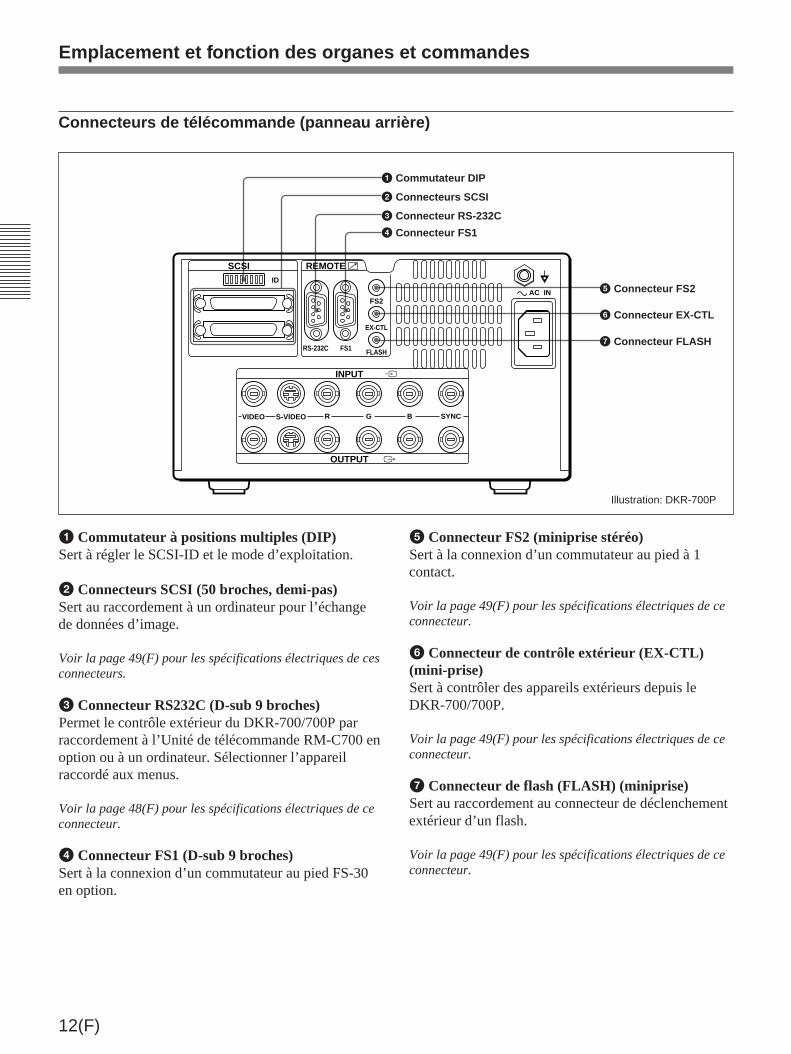
12(F)
⁄
SCSI REMOTE
INPUT
OUTPUT
FS2
EX-CTL
FLASHRS-232C FS1
VIDEO S-VIDEO R G B SYNC
Ú
…
AC IN
ID
1 Commutateur à positions multiples (DIP)Sert à régler le SCSI-ID et le mode d’exploitation.
2 Connecteurs SCSI (50 broches, demi-pas)Sert au raccordement à un ordinateur pour l’échangede données d’image.
Voir la page 49(F) pour les spécifications électriques de cesconnecteurs.
3 Connecteur RS232C (D-sub 9 broches)Permet le contrôle extérieur du DKR-700/700P parraccordement à l’Unité de télécommande RM-C700 enoption ou à un ordinateur. Sélectionner l’appareilraccordé aux menus.
Voir la page 48(F) pour les spécifications électriques de ceconnecteur.
4 Connecteur FS1 (D-sub 9 broches)Sert à la connexion d’un commutateur au pied FS-30en option.
5 Connecteur FS2 (miniprise stéréo)Sert à la connexion d’un commutateur au pied à 1contact.
Voir la page 49(F) pour les spécifications électriques de ceconnecteur.
6 Connecteur de contrôle extérieur (EX-CTL)(mini-prise)Sert à contrôler des appareils extérieurs depuis leDKR-700/700P.
Voir la page 49(F) pour les spécifications électriques de ceconnecteur.
7 Connecteur de flash (FLASH) (miniprise)Sert au raccordement au connecteur de déclenchementextérieur d’un flash.
Voir la page 49(F) pour les spécifications électriques de ceconnecteur.
5 Connecteur FS2
6 Connecteur EX-CTL
7 Connecteur FLASH
Illustration: DKR-700P
Emplacement et fonction des organes et commandes
1 Commutateur DIP
2 Connecteurs SCSI
3 Connecteur RS-232C
4 Connecteur FS1
Connecteurs de télécommande (panneau arrière)

13(F)
Unité de télécommande RM-C700 (en option)
Opérations d’enregistrement/reproduction
Pour les touches, voir la description des touchescorrespondantes sur le DKR-700/700P.
MENU IMAGE LIST PLAY AUTOPLAY CAPTURE RECSOURCE
ALLERASEERASEDISP DISC
NAME ID NO +--
1 ! 2@ 3# 4$ 5% 6" 7&
8* 9(
0 ) -_
/ :
Q W E R T Y U I O P
SHIFT A S D F G H J K L
Z X C V B N M
=+ , .
SPC
DEL EXE
N n N n
RM-C700
…( X r
INIT
Touche AUTO PLAY
Câble de racordement: L’insérer dans le connecteur RS-232C sur le panneau arrière du DKR-700/700P.
Touches de recherche
Touche PLAY (
Touches [+]/[–]
Touche SOURCE …
Touche CAPTURE X
Touche REC r(enregistrement)
Touche ERASE
Touche ALL ERASE/INIT
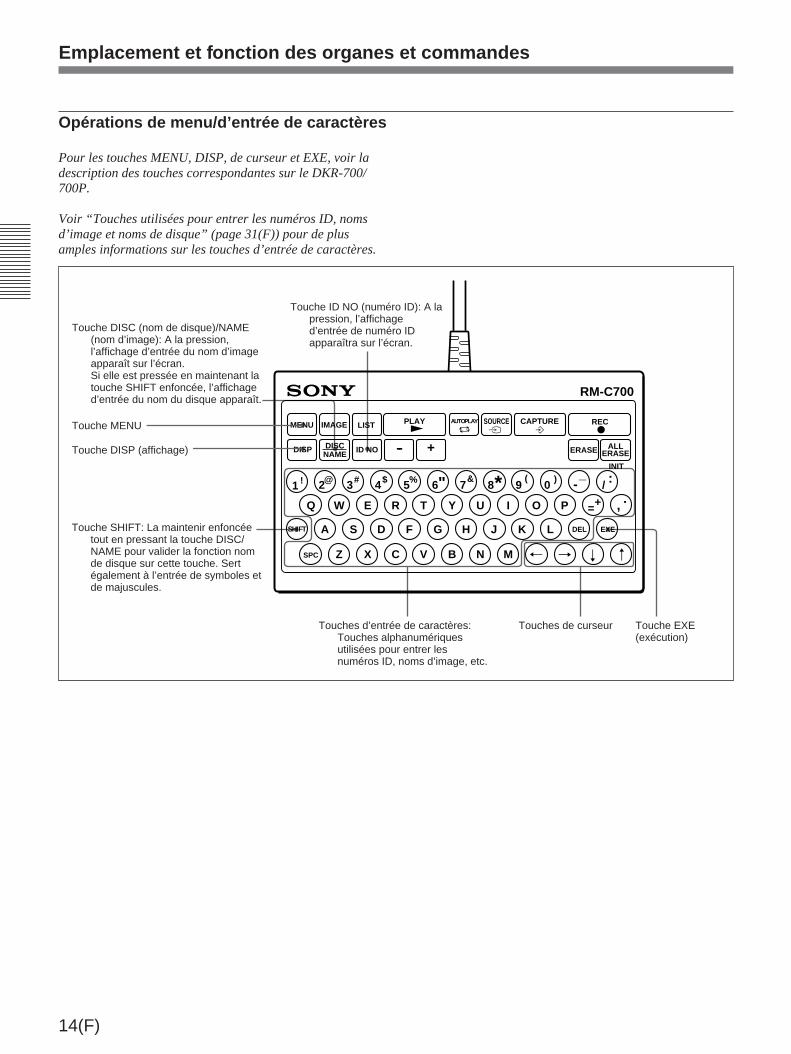
14(F)
MENU IMAGE LIST
ALLERASEERASEDISP +--
1 ! 2@ 3# 4$ 5% 6" 7&
8* 9(
0 ) -_
/ :
Q W E R T Y U I O P
SHIFT A S D F G H J K L
Z X C V B N M
=+ , .
SPC
DEL EXE
N n N n
RM-C700
PLAY AUTOPLAY CAPTURE RECSOURCE
DISCNAME ID NO
…( X r
INIT
Opérations de menu/d’entrée de caractères
Pour les touches MENU, DISP, de curseur et EXE, voir ladescription des touches correspondantes sur le DKR-700/700P.
Voir “Touches utilisées pour entrer les numéros ID, nomsd’image et noms de disque” (page 31(F)) pour de plusamples informations sur les touches d’entrée de caractères.
Emplacement et fonction des organes et commandes
Touche DISP (affichage)
Touche SHIFT: La maintenir enfoncéetout en pressant la touche DISC/NAME pour valider la fonction nomde disque sur cette touche. Sertégalement à l’entrée de symboles etde majuscules.
Touche ID NO (numéro ID): A lapression, l’affichaged’entrée de numéro IDapparaîtra sur l’écran.
Touche EXE(exécution)
Touches de curseurTouches d’entrée de caractères:Touches alphanumériquesutilisées pour entrer lesnuméros ID, noms d’image, etc.
Touche DISC (nom de disque)/NAME(nom d’image): A la pression,l’affichage d’entrée du nom d’imageapparaît sur l’écran.Si elle est pressée en maintenant latouche SHIFT enfoncée, l’affichaged’entrée du nom du disque apparaît.
Touche MENU
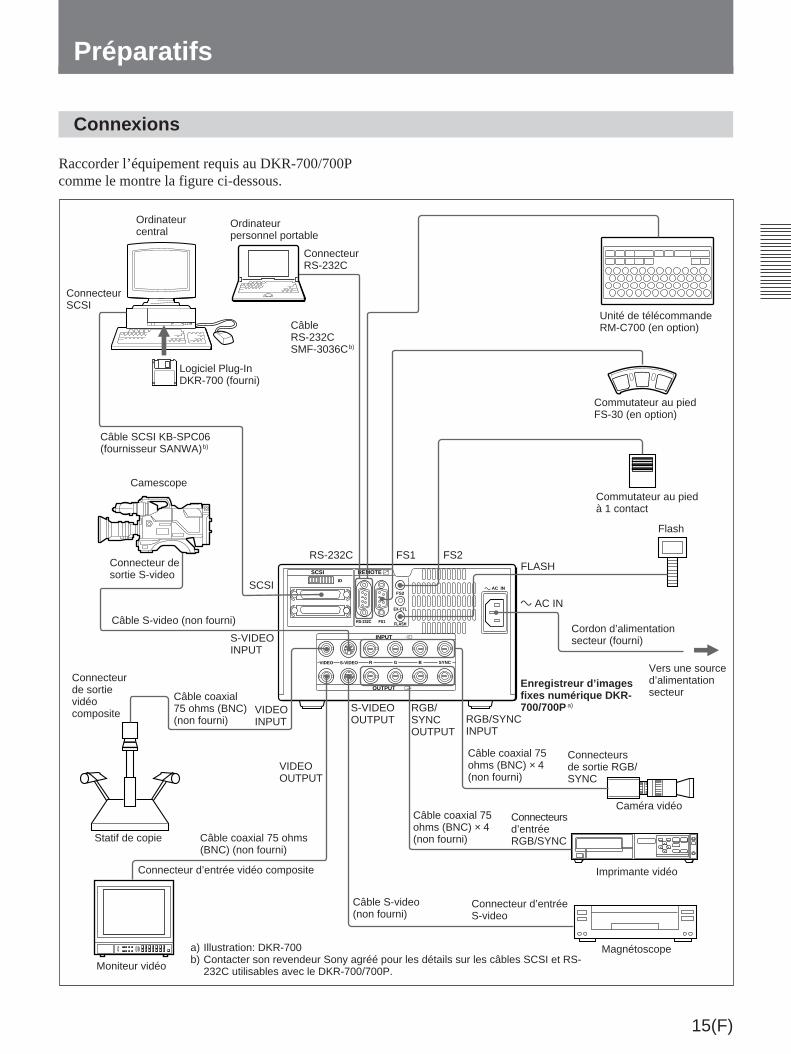
15(F)
Connexions
Préparatifs
Raccorder l’équipement requis au DKR-700/700Pcomme le montre la figure ci-dessous.
Ordinateurcentral
ConnecteurSCSI
Ordinateurpersonnel portable
ConnecteurRS-232C
CâbleRS-232CSMF-3036Cb)
Logiciel Plug-InDKR-700 (fourni)
Câble SCSI KB-SPC06(fournisseur SANWA)b)
Camescope
Connecteur desortie S-video
Câble S-video (non fourni)
Connecteurde sortievidéocomposite
Statif de copie Câble coaxial 75 ohms(BNC) (non fourni)
Connecteur d’entrée vidéo composite
Moniteur vidéo
Unité de télécommandeRM-C700 (en option)
Commutateur au piedFS-30 (en option)
Commutateur au piedà 1 contact
Flash
Cordon d’alimentationsecteur (fourni)
Vers une sourced’alimentationsecteur
Enregistreur d’imagesfixes numérique DKR-700/700P a)
Câble coaxial 75ohms (BNC) × 4(non fourni)
Connecteursde sortie RGB/SYNC
Câble coaxial 75ohms (BNC) × 4(non fourni)
Connecteursd’entréeRGB/SYNC
Câble S-video(non fourni)
Connecteur d’entréeS-video
Imprimante vidéo
Magnétoscope
RS-232C FS1 FS2FLASH
SCSI
S-VIDEOINPUT
Câble coaxial75 ohms (BNC)(non fourni)
VIDEOINPUT
VIDEOOUTPUT
S-VIDEOOUTPUT
RGB/SYNCOUTPUT
RGB/SYNCINPUT
⁄ AC IN
a) Illustration: DKR-700b) Contacter son revendeur Sony agréé pour les détails sur les câbles SCSI et RS-
232C utilisables avec le DKR-700/700P.
Caméra vidéo
⁄
SCSI REMOTE
INPUT
OUTPUT
FS2
EX-CTL
FLASHRS-232C FS1
VIDEO S-VIDEO R G B SYNC
Ú
…
AC IN
ID

16(F)
Réglage du commutateur DIP
Régler le commutateur DIP comme requis. (Poser leSCSI-ID si l’interface SCSI est utilisée.)
Commutateur DIP
Réglage et fonction de chaque commutateur
Préparatifs
Numéro decommutateur
Fonction Réglage
1 Terminaison deconnecteurSCSI
Régler à ON pour validerla terminaison SCSIinterne.
1 2 3 4 5 6 7 8ON
2 Sélectionner latemporisationpour la captured’une imageentrée dans lamémoire enutilisant uncommutateur aupied raccordéau connecteurFS1 ou FS2.
Voir le tableau ci-dessous.
3 Sélectionner latemporisationpour la captured’une imageentrée dans lamémoire enutilisant uncommutateur aupied raccordéau connecteurFS1 ou FS2.
Voir le tableau ci-dessous.
4 réservé
Réglages de temporisation pour la capture d’images
a) Quand le commutateur 2 est réglé à “ON” et lecommutateur 3 à “OFF”, alors même si le poste Flash dumenu d’implantation de système est réglé à On, le signaln’est pas sorti au connecteur FLASH.
b) Voir “Temporisation pour la capture d’une image avec lecommutateur au pied” (page 53(F)) pour de plus amplesinformations sur les temporisations 1 à 3.
Réglages SCSI-ID
Régler à OFF
5 réservé Régler à OFF
6 SCSI-ID Voir le Tableau desréglages SCSI-ID.
7 SCSI-ID Voir le Tableau desréglages SCSI-ID.
8 Voir le Tableau desréglages SCSI-ID.
SCSI-ID
Commutateur2
Commutateur3
Temporisation pour lacapture d’image dans lamémoire
OFF OFF Troisième trame aprèsl’entrée du signal dedéclenchement.(Temporisation 1) b)
OFF ON Seconde trame aprèsl’entrée du signal dedéclenchement.(Temporisation 2) b)
ONa) OFFa) Première trame aprèsl’entrée du signal dedéclenchement.(Temporisation 3) b)
SCSI-ID 0 1 2 3 4 5 6 7
Commutateur6
OFF OFF OFF OFF ON ON ON ON
Commutateur7
OFF OFF ON ON OFF OFF ON ON
Commutateur8
OFF ON OFF ON OFF ON OFF ON

17(F)
MiniDisc (disque de donnéesMD)
Le DKR-700/700P utilise des MiniDisc (disque dedonnées MMD-140 ou équivalent).
Utilisation de MiniDisc
• Ne pas ouvrir le volet de protection. Le contact directavec le disque pourrait endommager ou salir lasurface, provoquant des erreurs ou rendant lesdonnées illisibles.
• Ne pas exposer les disques en plein soleil, lessoumettre à des températures élevées, ou les placerdans un environnement poussiéreux.
• Le nettoyage des MiniDisc est inutile.
Protection contre l’effacement accidentel
Quand plus de données sont inscrites sur un disquepréenregistré (plein), les anciennes données peuventêtre perdues. Pour prévenir tout effacement accidentelde données importantes, glisser le curseurd’interdiction d’écriture comme indiqué surl’illustration.
A l’insertion d’un disque interdit d’écriture dans leDKR-700/700P, les opérations d’enregistrement serontimpossibles. Ramener le curseur d’interdictiond’écriture à sa position initiale pour permettre leréenregistrement du disque.
Etiquetage des disques
Coller l’étiquette fournie sur le disque et noter lecontenu du disque. Si l’étiquette est pleine, laremplacer par une neuve. Si une nouvelle étiquette estcollée sur l’ancienne, ou si l’étiquette est malpositionnée, cela peut provoquer un mauvaisfonctionnement et l’unité de disque peut êtreendommagée.
Volet deprotection
MD
Curseur d’interdiction d’écriture
Etiquette (fournie avec ledisque)

18(F)
Préparatifs
Activation du DKR-700/700P etinsertion/retrait d’un disque
Activation du DKR-700/700P
Mettre l’interrupteur POWER sur ON.
Le témoin POWER s’allume et le DKR-700/700P semet en service.
Au bout de quelques secondes, la touche SOURCEs’allume, et les touches du panneau avant deviennentopérantes. Un bip retentit si “Beep” du menu SystemSetup est réglé à On.
Voir la page 45(F) pour l’activation du bip.
L’interrupteur POWER peut être mis sur ON ou OFFquand un disque est chargé dans l’appareil.
Insertion d’un disque
Insérer le disque dans le logement dans le sens de laflèche, le côté portant la flèche dirigé vers le haut.
Remarque
L’orientation d’un Minidisc est différente de celled’une disquette ou d’un disque MO.
A l’activation du DKR-700/700P, le témoin BUSYs’allume et le DKR-700/700P commence à vérifier lesdonnées sur le disque.
Le contrôle terminé, le témoin BUSY s’éteint et un bipretentit si “Beep” du menu System Setup a été réglé àOn.
Si le disque n’est pas initialisé ou initialisé dans unformat incompatible avec le DKR-700/700PLe témoin ALL ERASE/INIT clignote (le message“Initialize” apparaît sur l’écran), et le DKR-700/700Ppasse en attente d’initialisation. Le témoin s’éteindra sila touche ALL ERSE/INIT n’est pas sollicitée dans lescinq secondes suivantes.
Voir “Initialisation d’un disque” ci-dessous pour les détails.
Retrait du disque
Appuyer sur la touche EJECT pour éjecter le disque.
Si le témoin BUSY est allumé ou clignotant à lapression de la touche EJECT, le disque est éjecté à lafin du traitement interne.Le disque peut être laissé dans le DKR-700/700P, saufpendant le transport de ce dernier.
Initialisation d’un disque
Pour enregistrer des images sur un disque avec leDKR-700/700P, le disque doit d’abord être initialisé àun format compatible avec le DKR-700/700P.
Remarque
L’initialisation d’un disque efface toutes les donnéesdessus. Contrôler les données stockées avant decommencer cette opération.
1 Insérer le disque à initialiser dans le DKR-700/700P et activer ce dernier (voir la sectionprécédente).
Le témoin ALL ERASE/INIT clignote (le message“Initialize” apparaît sur l’écran.)
Logement de disque
Témoin BUSY
Touche EJECT
InterrupteurPOWER
Minidisc
Témoin POWER
Touche et témoinALL ERASE/INIT
Touche ALL ERASE/INIT
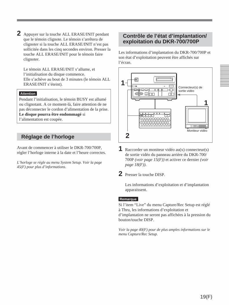
19(F)
2 Appuyer sur la touche ALL ERASE/INIT pendantque le témoin clignote. Le témoin s’arrêtera declignoter si la touche ALL ERASE/INIT n’est passollicitée dans les cinq secondes environ. Presser latouche ALL ERASE/INIT pour le témoin faireclignoter.
Le témoin ALL ERASE/INIT s’allume, etl’initialisation du disque commence.Elle s’achève au bout de 3 minutes (le témoin ALLERASE/INIT s’éteint).
Attention
Pendant l’initialisation, le témoin BUSY est alluméou clignotant. A ce moment-là, faire attention de nepas déconnecter le cordon d’alimentation de la prise.Le disque pourra être endommagé sil’alimentation est coupée.
Réglage de l’horloge
Avant de commencer à utiliser le DKR-700/700P,régler l’horloge interne à la date et l’heure correctes.
L’horloge se règle au menu System Setup. Voir la page45(F) pour plus d’informations.
Contrôle de l’état d’implantation/exploitation du DKR-700/700P
Les informations d’implantation du DKR-700/700P etson état d’exploitation peuvent être affichés surl’écran.
1 Raccorder un moniteur vidéo au(x) connecteur(s)de sortie vidéo du panneau arrière du DKR-700/700P (voir page 15(F)) et activer ce dernier (voirpage 18(F)).
2 Presser la touche DISP.
Les informations d’exploitation et d’implantationapparaissent.
Remarque
Si l’item “Live” du menu Capture/Rec Setup est régléà Thru, les informations d’exploitation etd’implantation ne seront pas affichées à la pression dubouton/touche DISP.
Voir la page 40(F) pour de plus amples informations sur lemenu Capture/Rec Setup.
1
1Connecteur(s) desortie vidéo
2Moniteur vidéo

20(F)
Les items 2 à 8 varient comme suit selon l’étatd’exploitation:Pendant la reproduction: Informations concernant
l’image présentement affichée sur l’écranAutrement: Information concernant les réglages à
utiliser pour la prochaine image à enregistrer.L’item 3 n’est pas affiché. Sous l’item 4,affichage du nombre d’images que le disque peutencore loger.
Changement du format d’affichageL’affichage de chaque item peut être activé oudésactivé au menu Disp Setup.
Voir la page 43(F) pour plus d’informations sur le réglagede l’affichage.
RGB
No Input
Disc Name
ABCDEFG12345678
123456789012345 Fine
67
10:18:36
1996-01-01
1 Mode d’exploitationSource d’entrée vidéo (Video, S Video ou RGB) sélectionnée ou état de fonctionnement(Capture ou Play)Si aucun signal vidéo n’est entré au connecteur d’entrée vidéo sélectionné (aux menus), lemessage “No Input” apparaîtra.
2 Numéro d’image
4 Heure d’enregistrement
3 Date d’enregistrement
5 Qualité d’image
6 Numéro ID
9 Zone d’affichage desmessages
8 Nom du disque7 Nom de l’image
Préparatifs

21(F)
Enregistrement d’images
Préparatifs pour l’enregistrement
1 Raccorder une caméra vidéo, un lecteur deLaserDisc, un magnétoscope, etc. au(x)connecteur(s) d’entrée vidéo correct(s) sur lepanneau arrière (voir la page 15(F)).
2 Raccorder un moniteur vidéo au(x) connecteur(s)de sortie vidéo correct(s) du panneau arrière (voirla page 15(F)).
3 Raccorder les appareils secondaires nécessaires(RM-C700, interrupteur au pied, flash, etc.) au(x)connecteur(s) de télécommande correct(s) dupanneau arrière (voir la page 15(F)).
4 Mettre le DKR-700/700P sous tension (voir lapage 18(F)).
Attention
Vérifier que la tension de réglage est conforme à latension du secteur avant d’utiliser le DKR-700P.
5 Insérer un disque dans le logement de disque, aprèsavoir vérifié qu’il est correctement initialisé et quele curseur d’interdiction d’écriture est réglé demanière à permettre l’enregistrement (voir la page18(F)).
6 Effectuer les réglages suivants aux menus:
1) Au menu principal, régler “Input” selon lesignal vidéo d’entrée à utiliser (voir la page38(F)).
2) Régler chaque item du menu Source Setupselon le signal vidéo d’entrée à utiliser (voir lapage 39(F)).
3) Régler les items nécessaires des menus SystemSetup (voir la page 44(F)) et Capture/Rec Setup(voir la page 40(F)) selon les appareilsextérieurs à utiliser.
Addition de numéros ID ou de noms d’imageaux imagesA l’enregistrement d’une image, son numéro d’imageet sa date d’enregistrement sont aussi automatiquementenregistrés. Quand le RM-C700 est utilisé, les numérosID et noms d’image peuvent également êtreenregistrés.
Voir “Gestion des données d’image (avec la RM-C700)”(page 31(F)), pour les informations concernant lesprocédures d’enregistrement du numéro ID et du nomd’image.
Caméra vidéo, lecteur deLaserDisc,magnétoscope, etc.
Connecteur(s)d’entrée vidéo
Moniteur vidéo
Connecteur(s)de sortie vidéo
Connecteur(s) de télécommande
RM-C700, interrupteur aupied, flash, etc.
1
2
4
4 5
6
3
Illustration: DKR-700
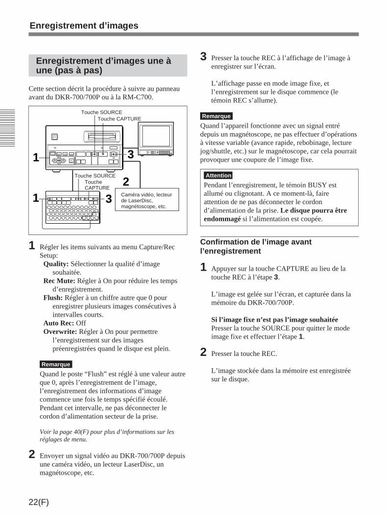
22(F)
1
2
3
1 3
Enregistrement d’images une àune (pas à pas)
Cette section décrit la procédure à suivre au panneauavant du DKR-700/700P ou à la RM-C700.
1 Régler les items suivants au menu Capture/RecSetup:Quality: Sélectionner la qualité d’image
souhaitée.Rec Mute: Régler à On pour réduire les temps
d’enregistrement.Flush: Régler à un chiffre autre que 0 pour
enregistrer plusieurs images consécutives àintervalles courts.
Auto Rec: OffOverwrite: Régler à On pour permettre
l’enregistrement sur des imagespréenregistrées quand le disque est plein.
Remarque
Quand le poste “Flush” est réglé à une valeur autreque 0, après l’enregistrement de l’image,l’enregistrement des informations d’imagecommence une fois le temps spécifié écoulé.Pendant cet intervalle, ne pas déconnecter lecordon d’alimentation secteur de la prise.
Voir la page 40(F) pour plus d’informations sur lesréglages de menu.
2 Envoyer un signal vidéo au DKR-700/700P depuisune caméra vidéo, un lecteur LaserDisc, unmagnétoscope, etc.
Touche SOURCETouche CAPTURE
Caméra vidéo, lecteurde LaserDisc,magnétoscope, etc.
ToucheCAPTURE
Touche SOURCE
3 Presser la touche REC à l’affichage de l’image àenregistrer sur l’écran.
L’affichage passe en mode image fixe, etl’enregistrement sur le disque commence (letémoin REC s’allume).
Remarque
Quand l’appareil fonctionne avec un signal entrédepuis un magnétoscope, ne pas effectuer d’opérationsà vitesse variable (avance rapide, rebobinage, lecturejog/shuttle, etc.) sur le magnétoscope, car cela pourraitprovoquer une coupure de l’image fixe.
Attention
Pendant l’enregistrement, le témoin BUSY estallumé ou clignotant. A ce moment-là, faireattention de ne pas déconnecter le cordond’alimentation de la prise. Le disque pourra êtreendommagé si l’alimentation est coupée.
Confirmation de l’image avantl’enregistrement
1 Appuyer sur la touche CAPTURE au lieu de latouche REC à l’étape 3.
L’image est gelée sur l’écran, et capturée dans lamémoire du DKR-700/700P.
Si l’image fixe n’est pas l’image souhaitéePresser la touche SOURCE pour quitter le modeimage fixe et effectuer l’étape 1.
2 Presser la touche REC.
L’image stockée dans la mémoire est enregistréesur le disque.
Enregistrement d’images

23(F)
Enregistrement automatiqued’images à intervalle
Cette section décrit la procédure à suivre au panneauavant du DKR-700/700P ou à la RM-C700.
1 Régler les items suivants au menu Capture/RecSetup:Quality: Sélectionner la qualité d’image
souhaitée.Rec Mute: Régler à On pour réduire les temps
d’enregistrement.Flush: Régler à un chiffre autre que 0 pour
enregistrer plusieurs images consécutives àintervalles courts. (Voir “Remarque” à l’étape1, page 22(F).)
Auto Rec: OffOverwrite: Régler à On pour permettre
l’enregistrement sur des imagespréenregistrées quand le disque est plein.
Voir la page 40(F) pour les réglages de menu.
2 Envoyer un signal vidéo au DKR-700/700P depuisune caméra vidéo, un lecteur LaserDisc, unmagnétoscope, etc.
3 Presser la touche REC.
L’affichage passe en mode image fixe, etl’enregistrement sur le disque démarre (le témoinAUTO s’allume).
Touche PLAYToucheSOURCE
Témoin AUTO
1 3
21 3
Touche PLAYTouche SOURCE
Remarque
Quand l’appareil fonctionne avec un signal entrédepuis un magnétoscope, ne pas effectuer d’opérationsà vitesse variable (avance rapide, rebobinage, lecturejog/shuttle, etc.) sur le magnétoscope, car cela pourraitprovoquer une coupure de l’image fixe.
Pour arrêter la reproductionPresser la touche SOURCE ou PLAY.
Enregistrement avec uncommutateur au pied à 1 contact
Choisir un des trois modes suivants pour lecommutateur au pied à 1 contact au menu Capture/RecSetup:• Capture/Rec• Capture• Alternate.
Voir la page 40(F) pour les réglages des menus.
Pour enregistrer en mode Capture/Rec
1 Effectuer les étapes 1 et 2 de la section“Enregistrement d’images une à une(pas à pas)” (page 22(F)).
2 Presser l’interrupteur au pied quand l’image àenregistrer s’affiche sur l’écran.
L’image est gelée sur l’écran, et l’enregistrementsur le disque commence.
Caméra vidéo, lecteurde LaserDisc,magnétoscope, etc.
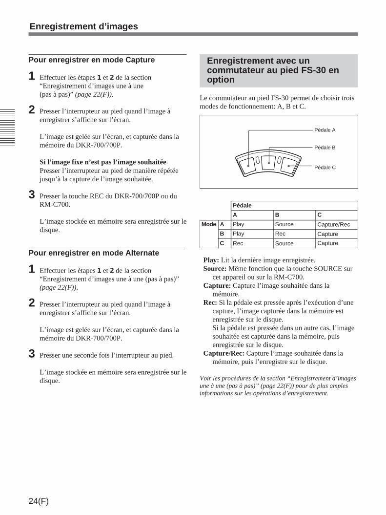
24(F)
Pour enregistrer en mode Capture
1 Effectuer les étapes 1 et 2 de la section“Enregistrement d’images une à une(pas à pas)” (page 22(F)).
2 Presser l’interrupteur au pied quand l’image àenregistrer s’affiche sur l’écran.
L’image est gelée sur l’écran, et capturée dans lamémoire du DKR-700/700P.
Si l’image fixe n’est pas l’image souhaitéePresser l’interrupteur au pied de manière répétéejusqu’à la capture de l’image souhaitée.
3 Presser la touche REC du DKR-700/700P ou duRM-C700.
L’image stockée en mémoire sera enregistrée sur ledisque.
Pour enregistrer en mode Alternate
1 Effectuer les étapes 1 et 2 de la section“Enregistrement d’images une à une (pas à pas)”(page 22(F)).
2 Presser l’interrupteur au pied quand l’image àenregistrer s’affiche sur l’écran.
L’image est gelée sur l’écran, et capturée dans lamémoire du DKR-700/700P.
3 Presser une seconde fois l’interrupteur au pied.
L’image stockée en mémoire sera enregistrée sur ledisque.
Enregistrement avec uncommutateur au pied FS-30 enoption
Le commutateur au pied FS-30 permet de choisir troismodes de fonctionnement: A, B et C.
Play: Lit la dernière image enregistrée.Source: Même fonction que la touche SOURCE sur
cet appareil ou sur la RM-C700.Capture: Capture l’image souhaitée dans la
mémoire.Rec: Si la pédale est pressée après l’exécution d’une
capture, l’image capturée dans la mémoire estenregistrée sur le disque.Si la pédale est pressée dans un autre cas, l’imagesouhaitée est capturée dans la mémoire, puisenregistrée sur le disque.
Capture/Rec: Capture l’image souhaitée dans lamémoire, puis l’enregistre sur le disque.
Voir les procédures de la section “Enregistrement d’imagesune à une (pas à pas)” (page 22(F)) pour de plus amplesinformations sur les opérations d’enregistrement.
Pédale A
Pédale B
Pédale C
Pédale
A B C
Mode A Play Source Capture/Rec
B Play Rec Capture
C Rec Source Capture
Enregistrement d’images

25(F)
Reproduction ou recherche d’images
Préparatifs pour la reproduction ou la recherche
1 Raccorder un moniteur vidéo, projecteur vidéo,etc. au(x) connecteur(s) de sortie vidéo correct(s)sur le panneau arrière du DKR-700/700P (voir lapage 15(F)).
2 Raccorder les appareils secondaires nécessaires(RM-C700, etc.) au(x) connecteur(s) detélécommande correct(s) sur le panneau arrière(voir la page 15(F)).
3 Mettre le DKR-700/700P sous tension (voir lapage 18(F)).
Attention
Vérifier que la tension de réglage est conforme à latension du secteur avant d’utiliser le DKR-700P.
4 Insérer un disque contenant des images dans lelogement de disque (voir la page 18(F)).
5 1) Au menu principal, régler “Video” selon lesignal vidéo de sortie à utiliser (voir la page38(F)).
2) Régler les items nécessaires au menu SystemSetup selon les appareils secondaires à utiliser(voir la page 44(F)).
Remarque
Quand l’appareil fonctionne avec un signal entrédepuis un magnétoscope, ne pas effectuer d’opérationsà vitesse variable (avance rapide, rebobinage, lecturejog/shuttle, etc.) sur le magnétoscope, car cela pourraitprovoquer une coupure de l’image reproduite.
RM-C700, etc.
Connecteur(s) detélécommande
Connecteur(s) desortie vidéo
Moniteur vidéo,projecteur vidéo,etc.
2
3
3 4
1 5
Illustration: DKR-700

26(F)
Reproduction des images une àune (pas à pas)
Cette section décrit la procédure à suivre au panneauavant du DKR-700/700P ou à la RM-C700.
1 Effectuer les réglages suivantes au menu PlaySetup.Réglage “Mode”
Quand une haute qualité est requise(affichage d’image principale):Sélectionner Main.
Quand un accès rapide est requis:Sélectionner Quick.
Si est Auto est sélectionné, l’image Main etl’image Quick sont reproduites toutes les deux.Sur le DKR-700P, la reproduction d’une image àaccès rapide se traduira par l’apparition d’un cadrenoir autour de l’image.
Remarque
A la lecture de l’image principale (à savoir Mainou Auto a été sélectionné à l’étape 1), si l’image àafficher a été sauvegardée sans compression (enréglant “Quality” à Non Comp au menu Capture &Rec Setup), l’affichage de l’image peut demanderun certain temps. (Aucune image n’apparaîtra surl’écran pendant ce temps.)
Réglage “Play Mute”Pour réduire le temps jusqu’à l’apparition
de l’image: Régler à “On”. Au changementd’image, l’écran devient vierge (autrementdit “assourdi”).
Si l’on ne souhaite pas supprimer(autrement dit “assourdir”) leschangements d’image: Régler à “Off”. Letemps nécessaire à l’apparition de l’imagesera plus long qu’au réglage “On”.
Voir la page 42(F) pour les réglages de menu.
2 Presser la touche PLAY.
Le DKR-700/700P démarre la reproduction (latouche PLAY s’allume).Si “Quick” a été sélectionné à l’étape 1, l’imageQuick apparaît, et si la touche PLAY est presséeencore une fois pendant la reproduction, l’imageMain apparaît.
3 Presser la touche [+] ou [–].Si la touche [+] est pressée: L’image à numéro
plus élevé s’affiche.Si la touche [–] est pressée: L’image à numéro
plus petit s’affiche.
Remarque
Si des images ont déjà été enregistrées sur ledisque avec un autre appareil, les numéros d’imagepourront parfois ne pas être consécutifs.
4 Répéter l’étape 3 pour afficher d’autres images.
1
2
1
3,4
3,42
Reproduction ou recherche d’images
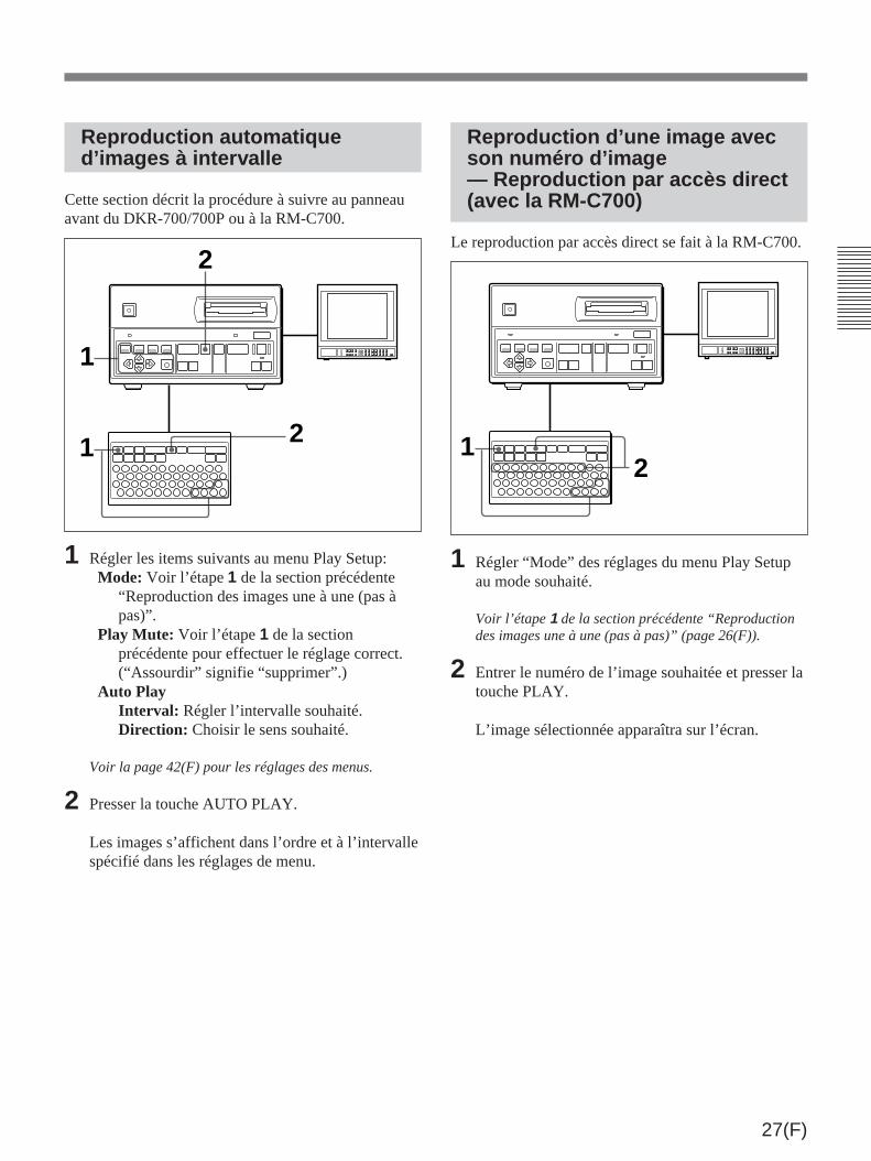
27(F)
2
1
2
1
Reproduction automatiqued’images à intervalle
Cette section décrit la procédure à suivre au panneauavant du DKR-700/700P ou à la RM-C700.
1 Régler les items suivants au menu Play Setup:Mode: Voir l’étape 1 de la section précédente
“Reproduction des images une à une (pas àpas)”.
Play Mute: Voir l’étape 1 de la sectionprécédente pour effectuer le réglage correct.(“Assourdir” signifie “supprimer”.)
Auto PlayInterval: Régler l’intervalle souhaité.Direction: Choisir le sens souhaité.
Voir la page 42(F) pour les réglages des menus.
2 Presser la touche AUTO PLAY.
Les images s’affichent dans l’ordre et à l’intervallespécifié dans les réglages de menu.
Reproduction d’une image avecson numéro d’image— Reproduction par accès direct(avec la RM-C700)
Le reproduction par accès direct se fait à la RM-C700.
1 Régler “Mode” des réglages du menu Play Setupau mode souhaité.
Voir l’étape 1 de la section précédente “Reproductiondes images une à une (pas à pas)” (page 26(F)).
2 Entrer le numéro de l’image souhaitée et presser latouche PLAY.
L’image sélectionnée apparaîtra sur l’écran.
12
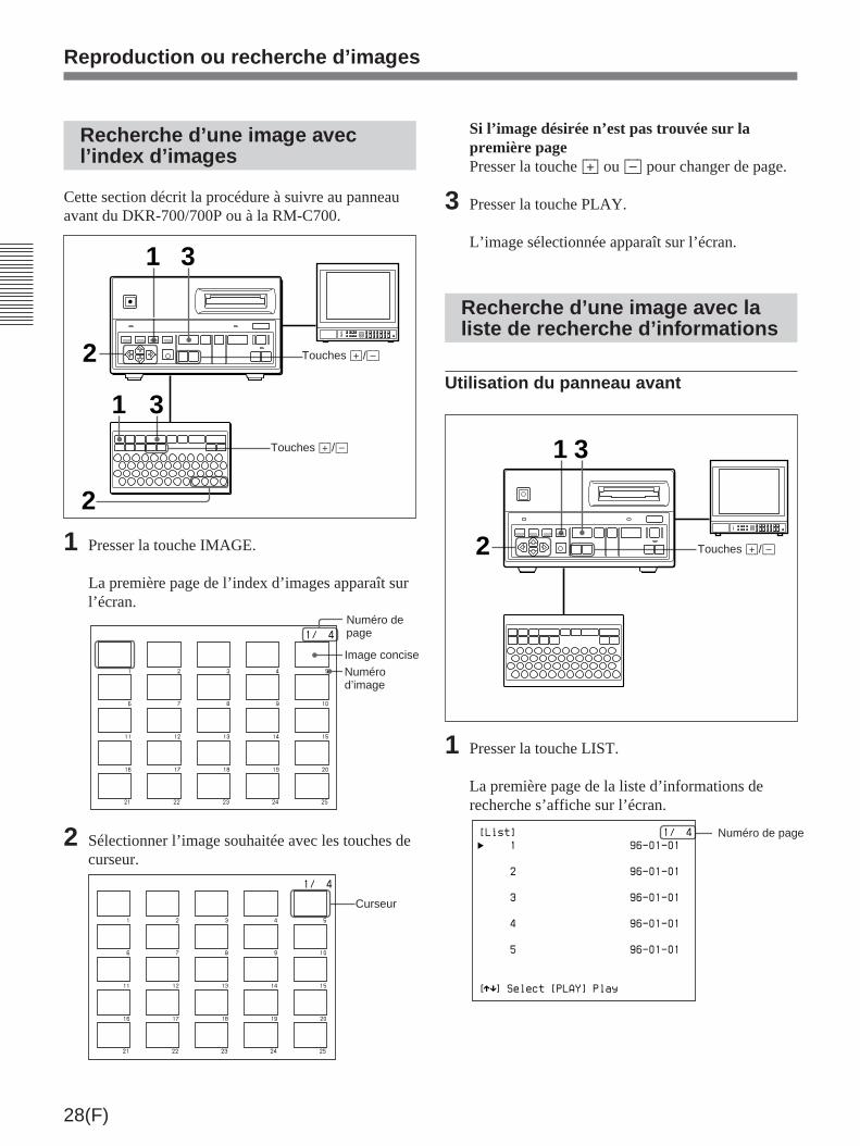
28(F)
Recherche d’une image avecl’index d’images
Cette section décrit la procédure à suivre au panneauavant du DKR-700/700P ou à la RM-C700.
1 Presser la touche IMAGE.
La première page de l’index d’images apparaît surl’écran.
1 2 3 4
6 7 8 9 10
11 12 13 14 15
16 17 18 19 20
21 22 23 24 25
5
1/ 4
2 Sélectionner l’image souhaitée avec les touches decurseur.
1 2 3 4
6 7 8 9 10
11 12 13 14 15
16 17 18 19 20
21 22 23 24 25
5
1/ 4
Si l’image désirée n’est pas trouvée sur lapremière pagePresser la touche [+] ou [–] pour changer de page.
3 Presser la touche PLAY.
L’image sélectionnée apparaît sur l’écran.
Recherche d’une image avec laliste de recherche d’informations
Utilisation du panneau avant
1 Presser la touche LIST.
La première page de la liste d’informations derecherche s’affiche sur l’écran.
[List]
1
2
3
4
5
[ ] Select [PLAY] Playµ
96-01-01
1/ 4
96-01-01
96-01-01
96-01-01
96-01-01
Reproduction ou recherche d’images
Curseur
Touches [+]/[–]
Touches [+]/[–]
1
2
2
31
3
Numérod’image
Image concise
Numéro depage
Touches [+]/[–]2
31
Numéro de page

29(F)
2 Sélectionner l’image souhaitée avec la touche ≥
ou ˘ .
[List]
1
2
3
4
5
[ ] Select [PLAY] Playµ
96-01-01
1/ 4
96-01-01
96-01-01
96-01-01
96-01-01
Si l’image souhaitée n’est pas trouvéePresser la touche [+] ou [–] pour changer de page.
3 Presser la touche PLAY.
L’image sélectionnée apparaîtra sur l’écran.
Utilisation de la RM-C700
1 Presser la touche LIST.
L’écran List Search apparaît.
[List Search]
Search: ID No
Keyword:
[ ] Select [ ] Set [EXEC]Executeµ
Mm
2 Amener le curseur (”) jusqu’à la ligne “Search”avec la touche ou ≥ .
3 Utiliser la touche ¿ ou ÷ pour sélectionner letype de recherche à effectuer.
Les sélections suivantes sont possibles:Image No (numéro d’image), Title (nom d’image),Date et ID No (numéro ID).
4 Avec la touche ou ≥ , amener le curseur (”)jusqu’à la ligne “Keyword”, puis presser la touche¿ ou ÷ pour afficher le curseur (_).
[List Search]
Search: ID No
Keyword:
[ ] Select [ ] Set [EXEC]Executeµ
Mm
5 Selon la sélection faite à l’étape 3, entrer lenuméro d’image, le nom d’image, la date ou lenuméro ID de l’image à rechercher.
[List Search]
Search: ID No
Keyword: 123456
[ ] Select [ ] Set [EXEC]Executeµ
Mm
Il est inutile d’entrer tous les chiffres ou caractères.La recherche est possible avec les premiers chiffresou caractères du numéro ID ou du nom d’image.
Curseur
Touches [+]/[–]1
2,3,4,7
8
56
Curseur
(à suivre)
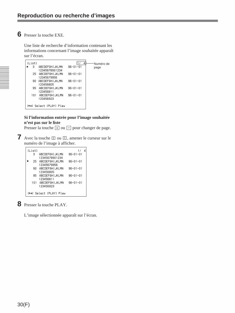
30(F)
Reproduction ou recherche d’images
6 Presser la touche EXE.
Une liste de recherche d’information contenant lesinformations concernant l’image souhaitée apparaîtsur l’écran.
[List]
3 ABCDEFGHIJKLMN
12345678901234
25 ABCDEFGHIJKLMN
12345679956
90 ABCDEFGHIJKLMN
123456805
95 ABCDEFGHIJKLMN
123456811
101 ABCDEFGHIJKLMN
123456923
[ ] Select [PLAY] Playµ
96-01-01
1/ 4
96-01-01
96-01-01
96-01-01
96-01-01
Si l’information entrée pour l’image souhaitéen’est pas sur le listePresser la touche [+] ou [–] pour changer de page.
7 Avec la touche ou ≥ , amener le curseur sur lenuméro de l’image à afficher.
[List]
3 ABCDEFGHIJKLMN
12345678901234
25 ABCDEFGHIJKLMN
12345679956
90 ABCDEFGHIJKLMN
123456805
95 ABCDEFGHIJKLMN
123456811
101 ABCDEFGHIJKLMN
123456923
[ ] Select [PLAY] Playµ
96-01-01
1/ 4
96-01-01
96-01-01
96-01-01
96-01-01
8 Presser la touche PLAY.
L’image sélectionnée apparaît sur l’écran.
Numéro depage

31(F)
MENU IMAGE
ALLERASEERASEDISP +--
1 ! 2@ 3# 4$ 5% 6" 7&
8* 9(
0 ) -_
/ :
Q W E R T Y U I O P
SHIFT A S D F G H J K L
Z X C V B N M
=+ , .
SPC
DEL EXE
N n N n
RM-C700
LIST PLAY AUTOPLAY CAPTURE RECSOURCE
DISCNAME ID NO
…( X r
INIT
Touches utilisées pour entrer les numéros ID, noms d’image et noms dedisque
Les touches suivantes sont utilisées pour l’entrée desnuméro ID, noms d’image et noms de disque.
Gestion des données d’image (avec la RM-C700)
Les numéros ID et les noms d’image peuvent êtreassociés à des données d’image, et des noms peuventêtre assignés aux disques à l’aide de l’Unité detélécommande RM-C700 en option.
Touche DISC/NAME: Quand elle est pressée, l’écrand’entrée de nom d’image s’affiche. Si elle estpressée en maintenant la touche SHIFT enfoncée,l’écran menu d’entrée de nom de disque s’affiche.
Touches numériques/de symboles: Utilisées pour entrerdes numéros et symboles. Pour produire le symboleau lieu du numéro, maintenir la touche SHIFT enfoncéetout en pressant la touche du symbole souhaité.
Touche SPC (espace):Sert à entrer desespaces.
Touche DEL(effacement):Sert à effacerles caractèreset symbolesentrés.
Touches alphabétiques:Servent à entrer deslettres. Pour entrerune majuscule,maintenir la toucheSHIFT enfoncée enappuyant sur la touchede la lettre souhaitée.
Touche ID NO (numéro ID):Quand cette touche estpressée, l’écran du menud’entrée de numéro IDs’affiche.
Touche SHIFT:• Maintenir cette touche enfoncée tout en pressant
la touche DISC/NAME pour valider la fonction nomde disque sur cette touche.
• Maintenir cette touche enfoncée tout en pressantune touche numérique/de symbole pour produire lesymbole sur cette touche.
• Maintenir cette touche enfoncée tout en pressantune touche alphabétique pour produire lamajuscule sur la touche.

32(F)
Le caractère entré apparaît, et le curseur se déplaced’une position vers la droite.
5 Vérifier le nom entré, et presser la touche EXE s’ilest correct.
Remarque
Un nom de disque posé ne peut pas être effacé.
Pose/modification d’un numéroID
Pose d’un numéro ID
1 Presser la touche ID NO.
L’écran d’entrée du numéro ID apparaît. ID No:
Mode:Off
[ ] Select [ ] Setµ
Mm
2 Avec la touche ou ≥ , amener le curseur (”)sur la ligne “ID No”.
3 Presser la touche ¿ ou ÷ pour afficher le curseur(_).
ID No:
Mode:Off
[ ] Select [ ] Setµ
Mm
Gestion des données d’image (avec la RM-C700)
Pose/modification du nom dudisque
1 1) Raccorder un moniteur vidéo au(x)connecteur(s) correct(s) sur le panneau arrièredu DKR-700/700P (voir la page 15(F)).
2) Insérer le disque dont le nom doit être posé oumodifié dans le DKR-700/700P, après avoirvérifié qu’il n’est pas interdit d’écriture (voir lapage 18(F)).
2 Presser la touche DISC/NAME en maintenant latouche SHIFT enfoncée.
L’écran d’entrée de nom du disque apparaît.
Disc Name:
[ ] Select [EXE] Endµ
3 Presser la touche ¿ ou ÷ pour afficher le curseuret l’amener à l’emplacement où des caractèresdoivent être entrés ou modifiés.
Disc Name:
[ ] Select [EXEC] End
Mm
4 Entrer le caractère souhaité (15 caractères max.)
Disc Name:Photo
[ ] Select [EXEC] End
Mm
Curseur
Curseur
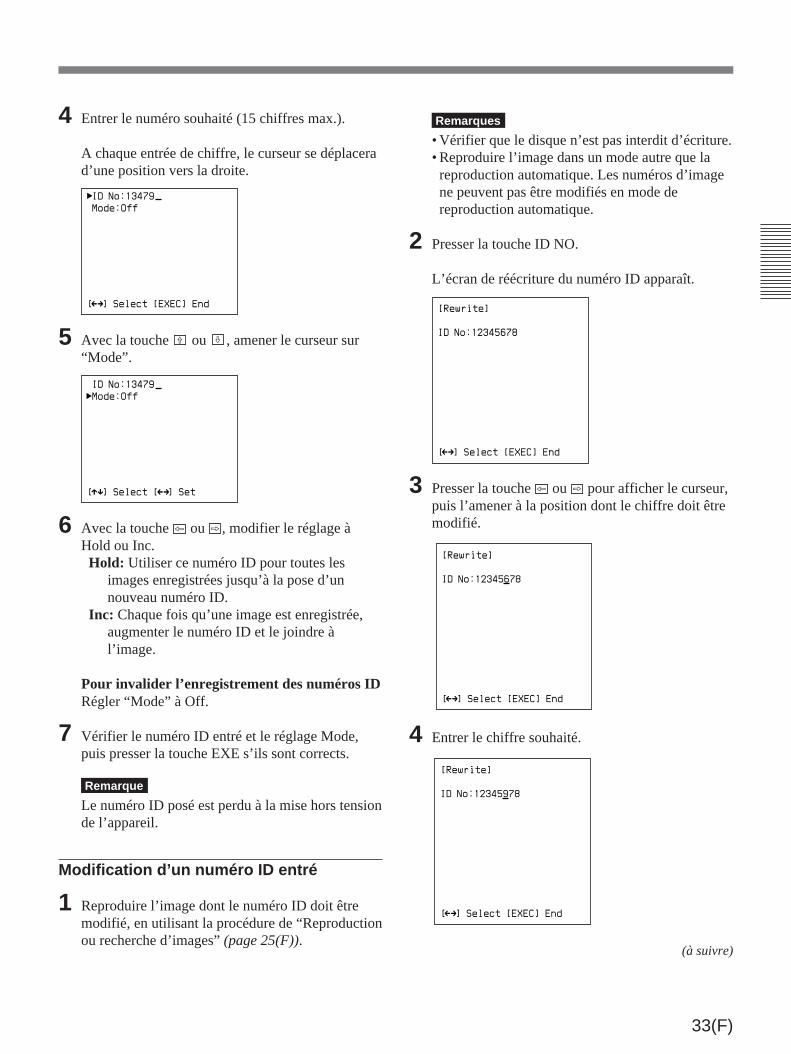
33(F)
Remarques
• Vérifier que le disque n’est pas interdit d’écriture.• Reproduire l’image dans un mode autre que lareproduction automatique. Les numéros d’imagene peuvent pas être modifiés en mode dereproduction automatique.
2 Presser la touche ID NO.
L’écran de réécriture du numéro ID apparaît.
[Rewrite]
ID No:12345678
[ ] Select [EXEC] End
Mm
3 Presser la touche ¿ ou ÷ pour afficher le curseur,puis l’amener à la position dont le chiffre doit êtremodifié.
[Rewrite]
ID No:12345678
[ ] Select [EXEC] End
Mm
4 Entrer le chiffre souhaité.
[Rewrite]
ID No:12345978
[ ] Select [EXEC] End
Mm
4 Entrer le numéro souhaité (15 chiffres max.).
A chaque entrée de chiffre, le curseur se déplacerad’une position vers la droite.
ID No:13479
Mode:Off
[ ] Select [EXEC] End
Mm
5 Avec la touche ou ≥ , amener le curseur sur“Mode”.
ID No:13479
Mode:Off
[ ] Select [ ] Setµ
Mm
6 Avec la touche ¿ ou ÷ , modifier le réglage àHold ou Inc.Hold: Utiliser ce numéro ID pour toutes les
images enregistrées jusqu’à la pose d’unnouveau numéro ID.
Inc: Chaque fois qu’une image est enregistrée,augmenter le numéro ID et le joindre àl’image.
Pour invalider l’enregistrement des numéros IDRégler “Mode” à Off.
7 Vérifier le numéro ID entré et le réglage Mode,puis presser la touche EXE s’ils sont corrects.
Remarque
Le numéro ID posé est perdu à la mise hors tensionde l’appareil.
Modification d’un numéro ID entré
1 Reproduire l’image dont le numéro ID doit êtremodifié, en utilisant la procédure de “Reproductionou recherche d’images” (page 25(F)).
(à suivre)
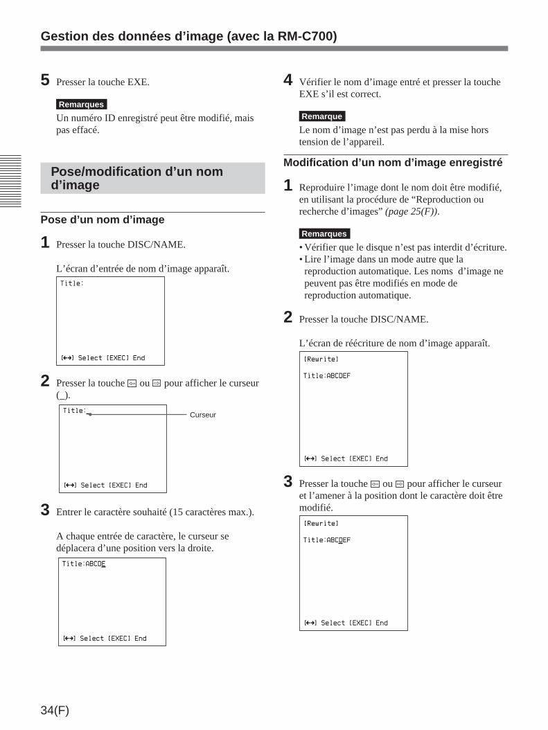
34(F)
Gestion des données d’image (avec la RM-C700)
4 Vérifier le nom d’image entré et presser la toucheEXE s’il est correct.
Remarque
Le nom d’image n’est pas perdu à la mise horstension de l’appareil.
Modification d’un nom d’image enregistré
1 Reproduire l’image dont le nom doit être modifié,en utilisant la procédure de “Reproduction ourecherche d’images” (page 25(F)).
Remarques
• Vérifier que le disque n’est pas interdit d’écriture.• Lire l’image dans un mode autre que lareproduction automatique. Les noms d’image nepeuvent pas être modifiés en mode dereproduction automatique.
2 Presser la touche DISC/NAME.
L’écran de réécriture de nom d’image apparaît.
[Rewrite]
[ ] Select [EXEC] End
Mm
Title:ABCDEF
3 Presser la touche ¿ ou ÷ pour afficher le curseuret l’amener à la position dont le caractère doit êtremodifié.
[Rewrite]
[ ] Select [EXEC] End
Mm
Title:ABCDEF
5 Presser la touche EXE.
Remarques
Un numéro ID enregistré peut être modifié, maispas effacé.
Pose/modification d’un nomd’image
Pose d’un nom d’image
1 Presser la touche DISC/NAME.
L’écran d’entrée de nom d’image apparaît.Title:
[ ] Select [EXEC] End
Mm
2 Presser la touche ¿ ou ÷ pour afficher le curseur(_).
Title:
[ ] Select [EXEC] End
Mm
3 Entrer le caractère souhaité (15 caractères max.).
A chaque entrée de caractère, le curseur sedéplacera d’une position vers la droite.
Title:ABCDE
[ ] Select [EXEC] End
Mm
Curseur
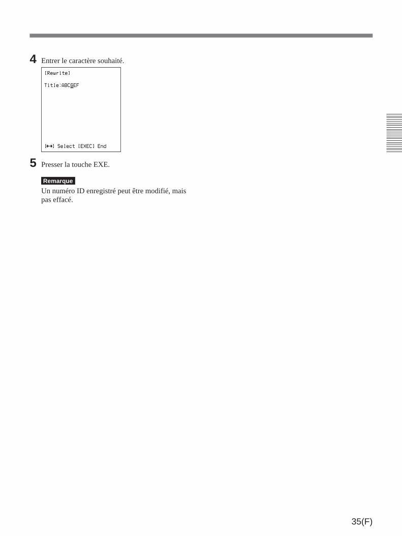
35(F)
4 Entrer le caractère souhaité.
[Rewrite]
[ ] Select [EXEC] End
Mm
Title:ABCGEF
5 Presser la touche EXE.
Remarque
Un numéro ID enregistré peut être modifié, maispas effacé.

36(F)
Effacement de toutes les imagessur le disque
Remarque
Avant de commencer la procédure, contrôler lesimages enregistrées sur le disque. Une fois les imageseffacées, il sera impossible de les récupérer.
1 Insérer le disque dans le DKR-700/700P (voir lapage 18(F)).
2 Presser la touche ALL ERASE/INIT (du DKR-700/700P ou de la RM-C700).
Le témoin ALL ERASE/INIT (du DKR-700/700P)clignote, et le message “ALL ERASE” apparaît surl’écran.
3 Presser une seconde fois la touche ALL ERASE/INIT pendant que le témoin clignote. Si elle n’estpas sollicitée pendant cinq secondes environ,clignote le témoin ERASE s’arrêtera de clignoter.La presser la touche ALL/ERASE/INIT denouveau pour la refaire clignoter le témoinERASE.
Le témoin ALL ERASE/INIT s’allume, etl’effacement total commence.
Attention
Pendant l’effacement, le témoin BUSY est alluméou clignotant. A ce moment-là, prendre garde de nepas déconnecter le cordon d’alimentation de la prise.Sinon, les données sur le disque pourraient êtreendommagées.
Cette section décrit la procédure à suivre au panneauavant du DKR-700/700P ou à la RM-C700.
Effacement des images une àune
1 Afficher l’image à effacer. (Voir la procédure àsuivre sous “Reproduction ou recherched’images” à la page 25(F).)
2 Presser la touche ERASE (du DKR-700/700P oude la RM-C700).
Le témoin ERASE (du DKR-700/700P) clignote,et le message “Erase” apparaît sur l’écran.
3 Presser une seconde fois la touche ERASE pendantque le témoin clignote. Si elle n’est pas sollicitéependant cinq secondes environ, le témoin ERASEs’arrêtera de clignoter. Dans ce cas, la presser latouche ERASE de nouveau pour la refaireclignoter le témoin ERASE.
Le témoin ERASE s’allume, et l’image disparaîtde l’écran. Le numéro d’image de l’image effacéeest omis dans la série.
Attention
Pendant l’effacement, le témoin BUSY est alluméou clignotant. A ce moment-là, prendre garde de nepas déconnecter le cordon d’alimentation de la prise.Sinon, les données sur le disque pourraient êtreendommagées.
Effacement d’images
Touche ALL et témoinERASE/INITTouche et témoin
ERASE
Touche ERASETouche ALL ERASE/INIT

37(F)
[Source Setup]
Adjust R:
G:
B:
Hue:
Color:
Reset
Sync on Green:
B/W:
Skew Comp:
0
0
0
0
0
0
0
Off
Off
Off
H Position:
V Position:
[ ] Select [ ] Set [MENU] Menuµ Mm
[Capture/Rec Setup]
Quality:
Rec Mute:
Flush Back:
Capture Trig:
FS2 Mode:
Frame/Field:
Review:
Review Mode:
Fine
Off
0 sec
FS2
Capture/Rec
Frame
[ ] Select [ ] Set [MENU] Menuµ Mm
[Play Setup]
Mode: Auto
Play Mute: Off
Auto Play
Interval: 5 sec
Direction: Forward
Auto Start: Off
[ ] Select [ ] Set [MENU] Menuµ Mm
Live: EE
Off
Play
Auto Rec:
Overwrite:
Off
Off
[Disp Setup]
Mode:
Image No:
Quality:
Remain:
Disc Name:
Title:
ID No:
Date:
Time:
On
On
Off
Off
Off
Off
Off
Off
Off
[ ] Select [ ] Set [MENU] Menuµ Mm
[System Setup]
Flash:
Rec Tally:
RS-232C:
Baud Rate:
Disp Color:
Beep:
Key Click:
Rec End:
Off
High
RM-C700
9600
FS1 mode: A
White
On
Off
Off
96-01-01
00:00
Date:
Time:
[ ] Select [ ] Set [MENU] Menuµ Mm
[User Setup]
Load: 1
Save: 1
[ ] Select [EXEC] Executeµ Mm
[Main]
Input: RGB
Video: Frame
Setup
Source
Capture/Rec
Play
Disp
System
User
[ ] Select [ ] Setµ Mm
”
Structure de menus
Le menu principal et six menus d’implantation sontprévus comme le montre la figure ci-dessus (figurepour le DKR-700).
Les menus permettent l’implantation des paramètresrelatifs aux opérations de l’appareil et à
l’environnement de fonctionnement.
Opérations de menu
Menu principal (voir la page 38(F))
Menu Source Setup(voir la page 39(F))
Menu Capture/Rec Setup(voir la page 40(F))
Menu Play Setup(voir la page 42(F))
Menu Disp Setup(voir la page 43(F))
Menu System Setup(voir la page 44(F))
Menu User Setup(voir la page 46(F))

38(F)
Touches pour les opérations de menus
Les touches ci-dessous servent aux opérations demenus.
Structure et emploi du menuprincipal
Presser la touche MENU.
Le menu principal apparaît.
[Main]
Input: RGB
Video: Frame
Setup
Source
Capture/Rec
Play
Disp
System
User
[ ] Select [ ] Setµ Mm
”
Les détails pour chaque item sont comme suit:Input: Sélectionne le type du signal vidéo d’entrée.Video: Sélectionne le mode de reproduction du signal
vidéo de sortie.Setup: Sélectionne le type d’implantation à effectuer,
et appelle le menu d’implantation correct.
Pour faire disparaître le menu principalPresser une seconde fois la touche MENU.
Sélection du type du signal vidéo d’entrée
Remarque
La sélection du type du signal vidéo d’entrée estimpossible pendant l’enregistrement, la reproductionou l’affichage d’images fixes (quand le témoinCAPTURE est allumée).
1 Presser la touche ˘ ou ≥ pour amener le curseursur la ligne “Input”.
[Main]
Input: RGB
Video: Frame
Setup
Source
Capture/Rec
Play
Disp
System
User
[ ] Select [ ] Setµ Mm
”
2 Presser la touche ¿ ou ÷ pour passer au réglagesouhaité.RGB: Signal RGBS Video: Signal S-videoVideo: Signal vidéo composite
Touche EXE:• Commute l’affichage du menu principal à un menu
d’implantation.• Confirme le réglage de date et d’heure.• Remet à zéro les valeurs de gain, teinte et couleur.
Touches de curseur
Touche EXEC:• Commute l’affichage du menu principal à un menu d’implantation.• Confirme le réglage de date et d’heure.• Remet à zéro les valeurs de gain, teinte et couleur.
Touche MENU:• Active/désactive l’affichage des menus.• Commute l’affichage d’un menu
d’implantation au menu principal.
Touches de curseur:Les touches ˘ et ≥ servent à sélectionnerl’item à régler, et les touches ¿ et ÷ àmodifier les réglages.
Touche MENU
Curseur
Opérations de menu

39(F)
Sélection du mode d’affichage du signalvidéo de sortie
Remarque
Le réglage suivant est valide pour la sortie d’imagesgelées ou de reproduction.
1 Presser la touche ˘ ou ≥ pour amener le curseursur la ligne “Video”.
[Main]
Input: RGB
Video: Frame
Setup
Source
Capture/Rec
Play
Disp
System
User
[ ] Select [ ] Setµ Mm
”
2 Presser la touche ¿ ou ÷ pour passer au réglagesouhaité.Frame: Reproduction de cadreField1/Field2: Affichage de trame. Changer de
trame en réglant à Field1 ou Field2.
Appel d’un menu d’implantation
1 Amener le curseur sur l’item souhaité avec latouche ˘ ou ≥ .
[Main]
Input: RGB
Video: Frame
Setup
Source
Capture/Rec
Play
Disp
System
User
[ ] Select [EXEC] Next Menuµ
L’implantation aura le contenu suivant:Source: Information d’implantation pour le signal
d’entréeCapture/Rec: Information d’implantation pour la
mémoire de cadres et les opérationsd’enregistrement sur disque
Play: Information d’implantation pour les opérationsde reproduction
a)
a)
Disp: Information d’implantation pour l’affichagedes conditions d’exploitation
System: Information d’implantation concernant lesystème DKR-700/700P
User: Informations d’implantation pour la pose desdonnées utilisateur (consignation/rappel)
2 Presser la touche EXEC (ou la touche EXE sur laRM-C700).
Le menu d’implantation sélectionné apparaîtra.
Structure et emploi du menuSource Setup
Appel du menu Source Setup
1 Au menu principal, presser la touche ˘ ou ≥pour amener le curseur sur la ligne “Source”.
[Main]
Input: RGB
Video: Frame
Setup
Source
Capture/Rec
Play
Disp
System
User
[ ] Select [EXEC] Next Menuµ
2 Presser la touche EXEC (ou EXE sur la RM-C700).
Le menu Source Setup apparaît.
[Source Setup]
Adjust R:
G:
B:
Hue:
Color:
Reset
Sync on Green:
B/W:
Skew Comp:
0
0
0
0
0
0
0
Off
Off
Off
H Position:
V Position:
[ ] Select [ ] Set [MENU] Menuµ Mm
a) Cet item existe seulement sur le DKR-700.
Pour revenir au menu principalPresser la touche MENU.
a)
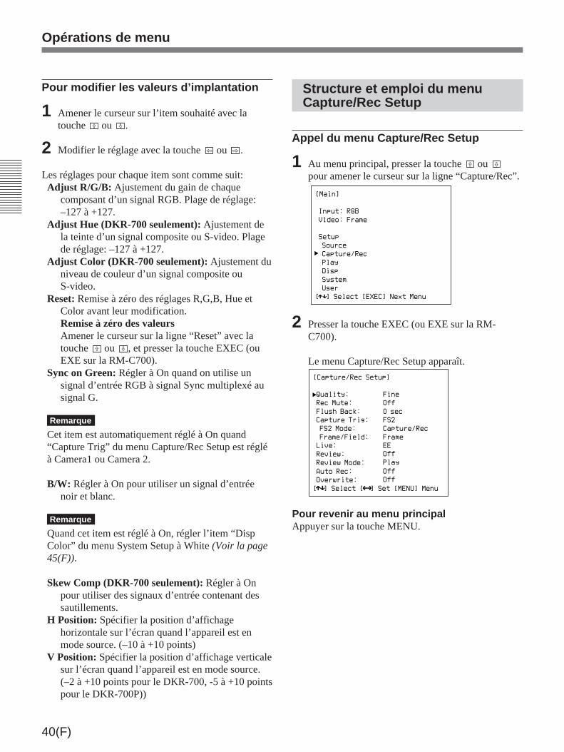
40(F)
Pour modifier les valeurs d’implantation
1 Amener le curseur sur l’item souhaité avec latouche ˘ ou ≥ .
2 Modifier le réglage avec la touche ¿ ou ÷ .
Les réglages pour chaque item sont comme suit:Adjust R/G/B: Ajustement du gain de chaque
composant d’un signal RGB. Plage de réglage:–127 à +127.
Adjust Hue (DKR-700 seulement): Ajustement dela teinte d’un signal composite ou S-video. Plagede réglage: –127 à +127.
Adjust Color (DKR-700 seulement): Ajustement duniveau de couleur d’un signal composite ouS-video.
Reset: Remise à zéro des réglages R,G,B, Hue etColor avant leur modification.Remise à zéro des valeursAmener le curseur sur la ligne “Reset” avec latouche ˘ ou ≥ , et presser la touche EXEC (ouEXE sur la RM-C700).
Sync on Green: Régler à On quand on utilise unsignal d’entrée RGB à signal Sync multiplexé ausignal G.
Remarque
Cet item est automatiquement réglé à On quand“Capture Trig” du menu Capture/Rec Setup est régléà Camera1 ou Camera 2.
B/W: Régler à On pour utiliser un signal d’entréenoir et blanc.
Remarque
Quand cet item est réglé à On, régler l’item “DispColor” du menu System Setup à White (Voir la page45(F)).
Skew Comp (DKR-700 seulement): Régler à Onpour utiliser des signaux d’entrée contenant dessautillements.
H Position: Spécifier la position d’affichagehorizontale sur l’écran quand l’appareil est enmode source. (–10 à +10 points)
V Position: Spécifier la position d’affichage verticalesur l’écran quand l’appareil est en mode source.(–2 à +10 points pour le DKR-700, -5 à +10 pointspour le DKR-700P))
Structure et emploi du menuCapture/Rec Setup
Appel du menu Capture/Rec Setup
1 Au menu principal, presser la touche ˘ ou ≥pour amener le curseur sur la ligne “Capture/Rec”.
[Main]
Input: RGB
Video: Frame
Setup
Source
Capture/Rec
Play
Disp
System
User
[ ] Select [EXEC] Next Menuµ
2 Presser la touche EXEC (ou EXE sur la RM-C700).
Le menu Capture/Rec Setup apparaît.
[Capture/Rec Setup]
Quality:
Rec Mute:
Flush Back:
Capture Trig:
FS2 Mode:
Frame/Field:
Review:
Review Mode:
Fine
Off
0 sec
FS2
Capture/Rec
Frame
[ ] Select [ ] Set [MENU] Menuµ Mm
Live: EE
Off
Play
Auto Rec:
Overwrite:
Off
Off
Pour revenir au menu principalAppuyer sur la touche MENU.
Opérations de menu
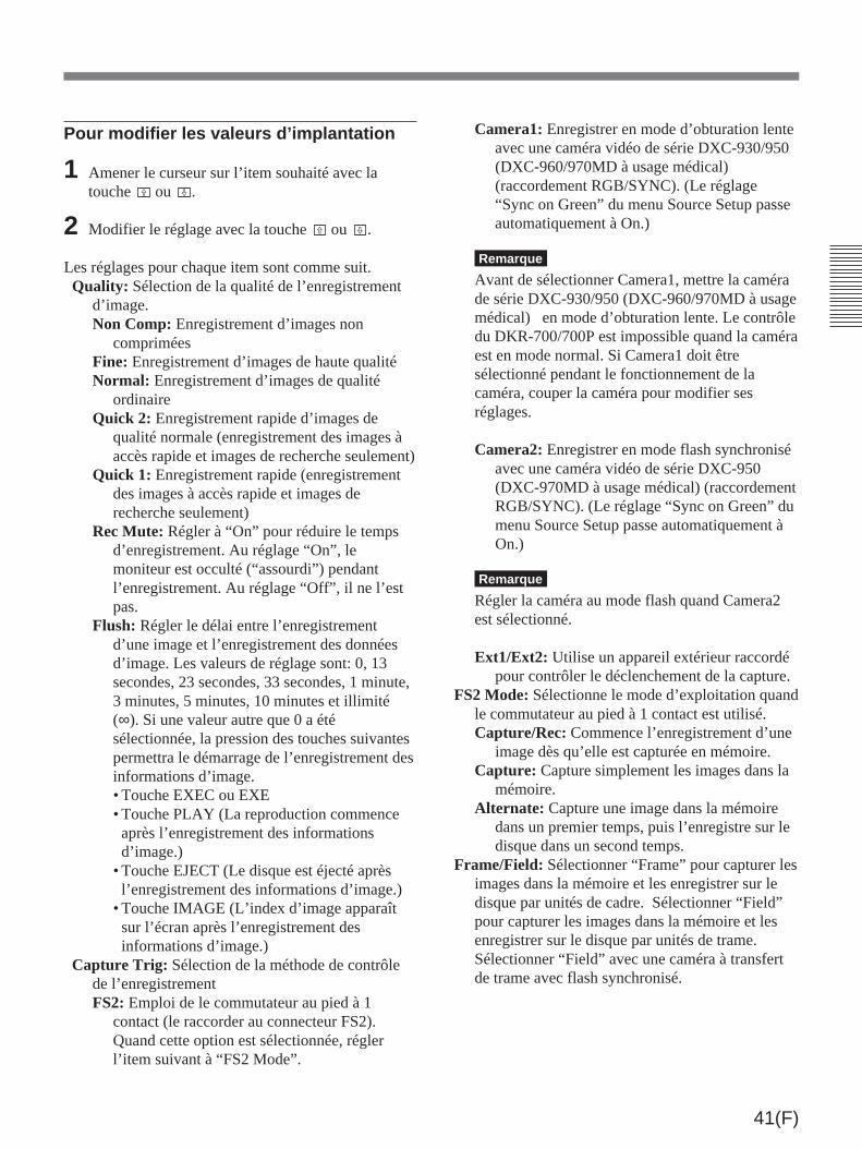
41(F)
Pour modifier les valeurs d’implantation
1 Amener le curseur sur l’item souhaité avec latouche ˘ ou ≥ .
2 Modifier le réglage avec la touche ˘ ou ≥ .
Les réglages pour chaque item sont comme suit.Quality: Sélection de la qualité de l’enregistrement
d’image.Non Comp: Enregistrement d’images non
compriméesFine: Enregistrement d’images de haute qualitéNormal: Enregistrement d’images de qualité
ordinaireQuick 2: Enregistrement rapide d’images de
qualité normale (enregistrement des images àaccès rapide et images de recherche seulement)
Quick 1: Enregistrement rapide (enregistrementdes images à accès rapide et images derecherche seulement)
Rec Mute: Régler à “On” pour réduire le tempsd’enregistrement. Au réglage “On”, lemoniteur est occulté (“assourdi”) pendantl’enregistrement. Au réglage “Off”, il ne l’estpas.
Flush: Régler le délai entre l’enregistrementd’une image et l’enregistrement des donnéesd’image. Les valeurs de réglage sont: 0, 13secondes, 23 secondes, 33 secondes, 1 minute,3 minutes, 5 minutes, 10 minutes et illimité(∞). Si une valeur autre que 0 a étésélectionnée, la pression des touches suivantespermettra le démarrage de l’enregistrement desinformations d’image.• Touche EXEC ou EXE• Touche PLAY (La reproduction commenceaprès l’enregistrement des informationsd’image.)
• Touche EJECT (Le disque est éjecté aprèsl’enregistrement des informations d’image.)
• Touche IMAGE (L’index d’image apparaîtsur l’écran après l’enregistrement desinformations d’image.)
Capture Trig: Sélection de la méthode de contrôlede l’enregistrementFS2: Emploi de le commutateur au pied à 1
contact (le raccorder au connecteur FS2).Quand cette option est sélectionnée, réglerl’item suivant à “FS2 Mode”.
Camera1: Enregistrer en mode d’obturation lenteavec une caméra vidéo de série DXC-930/950(DXC-960/970MD à usage médical)(raccordement RGB/SYNC). (Le réglage“Sync on Green” du menu Source Setup passeautomatiquement à On.)
Remarque
Avant de sélectionner Camera1, mettre la camérade série DXC-930/950 (DXC-960/970MD à usagemédical) en mode d’obturation lente. Le contrôledu DKR-700/700P est impossible quand la caméraest en mode normal. Si Camera1 doit êtresélectionné pendant le fonctionnement de lacaméra, couper la caméra pour modifier sesréglages.
Camera2: Enregistrer en mode flash synchroniséavec une caméra vidéo de série DXC-950(DXC-970MD à usage médical) (raccordementRGB/SYNC). (Le réglage “Sync on Green” dumenu Source Setup passe automatiquement àOn.)
Remarque
Régler la caméra au mode flash quand Camera2est sélectionné.
Ext1/Ext2: Utilise un appareil extérieur raccordépour contrôler le déclenchement de la capture.
FS2 Mode: Sélectionne le mode d’exploitation quandle commutateur au pied à 1 contact est utilisé.Capture/Rec: Commence l’enregistrement d’une
image dès qu’elle est capturée en mémoire.Capture: Capture simplement les images dans la
mémoire.Alternate: Capture une image dans la mémoire
dans un premier temps, puis l’enregistre sur ledisque dans un second temps.
Frame/Field: Sélectionner “Frame” pour capturer lesimages dans la mémoire et les enregistrer sur ledisque par unités de cadre. Sélectionner “Field”pour capturer les images dans la mémoire et lesenregistrer sur le disque par unités de trame.Sélectionner “Field” avec une caméra à transfertde trame avec flash synchronisé.

42(F)
Overwrite: Régler sur On pour permettrel’enregistrement sur des images déjà enregistréessur disque.
Structure et emploi du menuPlay Setup
Appel du menu Play Setup
1 Au menu principal, presser la touche ˘ ou ≥ pouramener le curseur sur la ligne “Play”.
[Main]
Input: RGB
Video: Frame
Setup
Source
Capture/Rec
Play
Disp
System
User
[ ] Select [EXEC] Next Menuµ
2 Presser la touche EXEC (ou EXE sur la RM-C700).
Le menu Play Setup apparaît.
[Play Setup]
Mode: Auto
Play Mute: Off
Auto Play
Interval: 5 sec
Direction: Forward
Auto Start: Off
[ ] Select [ ] Set [MENU] Menuµ Mm
a) Cet item est réglé à Main sur le DKR-700P à l’expédition.
Pour revenir au menu principalPresser la touche MENU.
a)
Live: Choisit si le signal vidéo d’entrée doit êtresorti sous forme de signal EE (électrique-à-électrique)1), ou passé directement aux sorties(en tant que simple signal en boucle “Thru”).Si cet item est réglé à EE/Thru ou Thru, l’item demenu suivant passera de “Review” à “Timer”.
Remarque
Quand un menu est affiché sur l’écran, la sortiesera un signal EE même si EE/Thru ou Thru estsélectionné. Eliminer le menu avant de régler cetitem.
EE: La sortie sera toujours un signal EE.EE/Thru: La sortie sera un signal EE, sauf
pendant l’enregistrement, où elle passera à unsignal Thru.
Thru: La sortie sera un signal Thru, sauf pendantla sortie d’une image de la mémoire interne duDKR-700/700P (par exemple quand la toucheCAPTURE est pressée).
Review/Timer: Quand l’item de menu précédent“Live” est réglé à EE, cet item sera “Review”.Quand “Live” est réglé à EE/Thru ou Thru, ilpassera à “Timer”.Review: Pour revoir automatiquement une image
après son enregistrement, régler cet item autemps de lecture souhaité. Le temps peut êtreréglé à 1 seconde, 3 secondes, 5 secondes, 7secondes, 10 secondes ou Cont (continu).Régler à Off pour couper cette fonction.
Timer: Choisit l’affichage ou non d’une image demémoire après son enregistrement. A On,l’image sauvegardée en mémoire s’afficherapendant quelques secondes, puis l’affichagereviendra à l’image d’entrée. A Off, l’imaged’entrée s’affichera immédiatement.
Review Mode: Sélectionner l’image à revoir. Auréglage “Capture”, l’image enregistrée dans lamémoire est revue; au réglage “Play”, la ou lesimages sur le disque sont revues.
Auto Rec: Règle l’intervalle auquel les imagesdoivent être enregistrées en enregistrementautomatique. Plage de réglage: 5 secondes à 60minutes. Régler à Off pour couper la fonctiond’enregistrement automatique.
Opérations de menu
1) Signal EE (électrique-à-électrique): Un signal entré dansle circuit d’enregistrement, qui passe vers les sortiesaprès avoir traversé les circuits électriques.
..........................................................................................................................................................................................................
a)
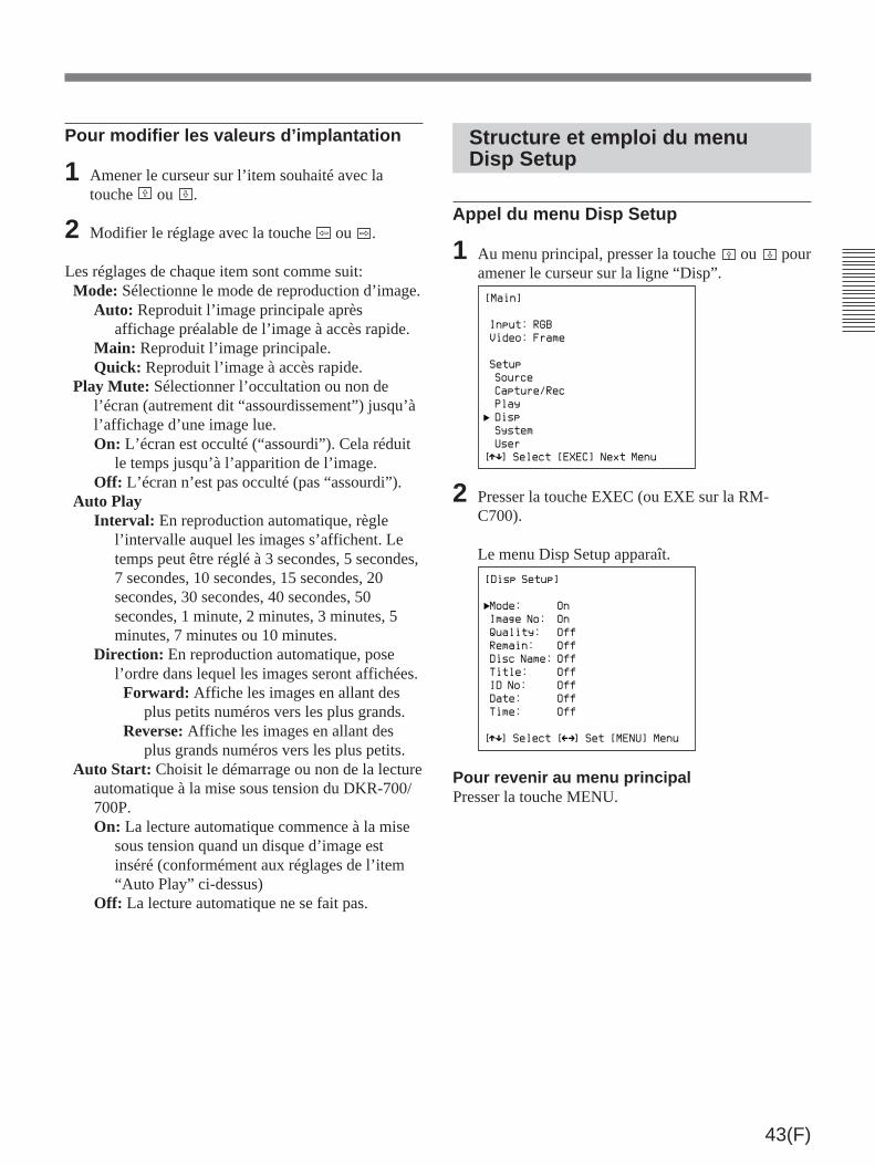
43(F)
Structure et emploi du menuDisp Setup
Appel du menu Disp Setup
1 Au menu principal, presser la touche ˘ ou ≥ pouramener le curseur sur la ligne “Disp”.
[Main]
Input: RGB
Video: Frame
Setup
Source
Capture/Rec
Play
Disp
System
User
[ ] Select [EXEC] Next Menuµ
2 Presser la touche EXEC (ou EXE sur la RM-C700).
Le menu Disp Setup apparaît.
[Disp Setup]
Mode:
Image No:
Quality:
Remain:
Disc Name:
Title:
ID No:
Date:
Time:
On
On
Off
Off
Off
Off
Off
Off
Off
[ ] Select [ ] Set [MENU] Menuµ Mm
Pour revenir au menu principalPresser la touche MENU.
Pour modifier les valeurs d’implantation
1 Amener le curseur sur l’item souhaité avec latouche ˘ ou ≥ .
2 Modifier le réglage avec la touche ¿ ou ÷ .
Les réglages de chaque item sont comme suit:Mode: Sélectionne le mode de reproduction d’image.
Auto: Reproduit l’image principale aprèsaffichage préalable de l’image à accès rapide.
Main: Reproduit l’image principale.Quick: Reproduit l’image à accès rapide.
Play Mute: Sélectionner l’occultation ou non del’écran (autrement dit “assourdissement”) jusqu’àl’affichage d’une image lue.On: L’écran est occulté (“assourdi”). Cela réduit
le temps jusqu’à l’apparition de l’image.Off: L’écran n’est pas occulté (pas “assourdi”).
Auto PlayInterval: En reproduction automatique, règle
l’intervalle auquel les images s’affichent. Letemps peut être réglé à 3 secondes, 5 secondes,7 secondes, 10 secondes, 15 secondes, 20secondes, 30 secondes, 40 secondes, 50secondes, 1 minute, 2 minutes, 3 minutes, 5minutes, 7 minutes ou 10 minutes.
Direction: En reproduction automatique, posel’ordre dans lequel les images seront affichées.Forward: Affiche les images en allant des
plus petits numéros vers les plus grands.Reverse: Affiche les images en allant des
plus grands numéros vers les plus petits.Auto Start: Choisit le démarrage ou non de la lecture
automatique à la mise sous tension du DKR-700/700P.On: La lecture automatique commence à la mise
sous tension quand un disque d’image estinséré (conformément aux réglages de l’item“Auto Play” ci-dessus)
Off: La lecture automatique ne se fait pas.

44(F)
Structure et emploi du menuSystem Setup
Appel du menu System Setup
1 Au menu principal, presser la touche ˘ ou ≥ pouramener le curseur sur la ligne “System”.
[Main]
Input: RGB
Video: Frame
Setup
Source
Capture/Rec
Play
Disp
System
User
[ ] Select [EXEC] Next Menuµ
2 Presser la touche EXEC (ou EXE sur la RM-C700).
Le menu System Setup apparaît.
[System Setup]
Flash:
Rec Tally:
RS-232C:
Baud Rate:
FS1 Mode:
Disp Color:
Beep:
Key Click:
Rec End:
Off
High
RM-C700
9600
A
White
On
Off
Off
96-01-01
00:00
Date:
Time:
[ ] Select [ ] Set [MENU] Menuµ Mm
Pour revenir au menu principalPresser la touche MENU.
Pour modifier les valeurs d’implantation
1 Amener le curseur sur l’item souhaité avec latouche ˘ ou ≥ .
2 Modifier le réglage avec la touche ¿ ou ÷ .
Ces réglages pour chaque item sont comme suit:Mode: Régler à On pour afficher le type du signal
d’entrée et l’état d’exploitation du DKR-700/700P.
Image No: Régler à On pour afficher le numérod’image de l’image suivante à enregistrer ou del’image présentement reproduite.
Quality: Régler à On pour afficher le réglage dequalité d’image pour l’enregistrement ou lareproduction.
Remain: Régler à On pour afficher le nombred’images pouvant être enregistrées dans l’espacerestant sur le disque.
Disc Name: Régler à On pour afficher le nom dudisque présentement dans le DKR-700/700P.
Title: Régler à On pour afficher le nom de l’imagesuivante à enregistrer ou de l’image présentementreproduite.
ID No: Régler à On pour afficher le numéro ID del’image suivante à enregistrer ou de l’imageprésentement reproduite.
Date: Régler à On pour afficher la dated’enregistrement (année/mois/jour) de l’imageprésentement reproduite.
Time: Régler à On pour afficher l’heured’enregistrement (heure/minutes/secondes) del’image présentement reproduite.
Opérations de menu

45(F)
2 Amener le curseur (_) sur l’item (jour, mois ouannée) à poser avec la touche ¿ ou ÷ .
3 Modifier la valeur de l’item sélectionné avec latouche ˘ ou ≥ .
4 Répéter les étapes 2 et 3 pour modifier d’autresitems. Passer à l’étape 5 une fois la datecorrectement posée.
5 Presser la touche EXEC (ou EXE sur la RM-C700).
Le curseur (_) disparaît.
Réglage de l’heure
1 Amener le curseur (”) sur la ligne “Time” avec latouche ˘ ou ≥ , et presser la touche ¿ ou ÷ pourafficher le curseur (_).
Le curseur (_) et l’indication “secondes”apparaissent.
2 Amener le curseur (_) sur l’item (secondes,minutes ou heure) à régler avec la touche ¿ ou ÷ .
Curseur
96-01-01
96-01-01
96-02-01
Pour modifier les valeurs d’implantation
1 Amener le curseur sur l’item souhaité avec latouche ˘ ou ≥ .
2 Modifier le réglage avec la touche ¿ ou ÷ .
Les réglages pour chaque item sont comme suit:Flash: Régler à On pour produire un signal de
déclenchement depuis le connecteur FLASH.Rec Tally: Sélectionner la polarité du signal Rec
Tally fourni par le connecteur FS2. Sélectionpossible: “High” ou “Low”.
RS-232C: Sélectionner l’appareil à raccorder auconnecteur RS-232C. (Cet item peut seulement serégler au panneau avant.)RM-C700: Unité de télécommande RM-C700Ext CPU: Un ordinateur. Dans ce cas, l’item
suivant (Baud Rate) doit également être réglé.Baud Rate: Quand le DKR-700/700P est contrôlé
depuis un ordinateur, le débit doit être réglé enfonction du réglage du port série de l’ordinateur.Valeurs disponibles: 1200, 2400, 4800 et 9600.
FS1 Mode: Sélectionner le mode d’exploitation lorsde l’utilisation du commutateur au pied FS-30 enoption. (Voir la page 24(F).)
Disp Color: Pour régler les couleurs des caractèresde l’affichage. Sélections possibles: blanc, rouge,vert, jaune, bleu, magenta et cyan.
Beep: Régler à On pour faire retentir un bip en casd’erreur et à l’achèvement des opérations. Dans cecas, les items suivants “Key Click” et “Rec End”peuvent également être réglés.
Key Click: Si réglé à On, le DKR-700/700P émet unbref déclic à la pression des touches du panneauavant ou de la RM-C700.
Rec End: Régler à “On” pour faire retentir un bip àla fin de l’enregistrement.
Date: La date peut être posée dans l’horloge interne.Time: L’heure peut être posée dans l’horloge interne.
Réglage de la date
1 Amener le curseur (”) sur la ligne “Date” avec latouche ˘ ou ≥ , et presser la touche ¿ ou ÷ pourafficher le curseur (_). (à suivre)
00:00:00
00:00:00
Curseur

46(F)
3 Modifier la valeur de l’item sélectionné avec latouche ˘ ou ≥ .
4 Répéter les étapes 2 et 3 pour modifier d’autresitems. Passer à l’étape 5 une fois l’heurecorrectement posée.
5 Presser la touche EXEC (ou EXE sur la RM-C700).
Le curseur (_) et l’indication “secondes”disparaissent.
Structure et emploi du menuUser Setup
Appel du menu User Setup
1 Au menu principal, appuyer sur le bouton/touche˘ ou ≥ pour amener le curseur sur la ligne
“User”.
[Main]
Input: RGB
Video: Frame
Setup
Source
Capture/Rec
Play
Disp
System
User
[ ] Select [ ] Setµ Mm
2 Presser le bouton EXEC (ou la touche EXE duRM-C700). Le menu User Setup apparaît.
[User Setup]
Load: 1
Save: 1
[ ] Select [EXEC] Executeµ Mm
Pour revenir au menu principalAppuyer sur le bouton/touche MENU.
Emploi du menu User Setup
Le menu User Setup permet la consignation desréglages de tous les menus sous forme de “donnéesutilisateur”, et leur rappel si nécessaire.
Consignation des données utilisateurTrois jeux de données utilisateur maximum, chacunidentifié par un numéro, peuvent être créés.
1 Régler tous les items de menu comme souhaité,puis appeler le menu User Setup.
2 Appuyer sur le bouton/touche ˘ ou ≥ pourdéplacer le curseur à la ligne “Save”.
[User Setup]
Load: 1
Save: 1
[ ] Select [EXEC] Executeµ Mm
3 Appuyer sur ¿ ou ÷ pour sélectionner 1, 2 ou 3comme numéro de consignation pour les réglagesde menu présents.
Un numéro en surbrillance en vidéo inverse estdéjà utilisé.
[User Setup]
Load: 1
Save: 2
[ ] Select [EXEC] Executeµ Mm
00:01:00
Opérations de menu

47(F)
4 Appuyer sur le bouton EXEC (ou la touche EXEdu RM-C700).
Les réglages de menu présents seront consignéssous forme de données d’utilisateur.
Rappel de données d’utilisateur
1 Appeler le menu User Setup.
2 Appuyer sur le bouton/touche ˘ ou ≥ pouramener le curseur à la ligne “Load”.
[User Setup]
Load: 1
Save: 1
[ ] Select [EXEC] Executeµ Mm
3 Appuyer sur ¿ ou ÷ pour sélectionner le numérode donnée d’utilisateur souhaité.
Les données dont le numéro sont en surbrillance envidéo inverse peuvent être rappelées.
[User Setup]
Load: 2
Save: 1
[ ] Select [EXEC] Executeµ Mm
4 Appuyer sur le bouton EXEC (ou la touche EXEsur le RM-C700).
Les réglages de menu présents sont remplacés parles données utilisateur rappelées, et le DKR-700/700P passe en mode de source.

48(F)
Appendices
Spécifications
Généralités
Classification des appareils• Type de production contre les déchargesélectriques: appareil de classe I
• Degré de protection contre les déchargesélectriques: appareil de classe B (DKR-700seulement)
• Degré de protection contre la pénétration nuisibled’eau: appareil ordinaire
• Degré de sécurité d’emploi en présence demélange anesthésiant inflammable: appareil nonprotégé
• Mode de fonctionnement: fonctionnement continuAlimentation DKR-700: Secteur de 120 V, 50/60
HzDKR-700P: Secteur de 220/230/
240 V au choix, 50/60 HzConsommation DKR-700: 0,6 A max.
DKR-700P: 0,3 A max.Température de fonctionnement
5 à 35˚C (41 à 95˚F)Humidité de fonctionnement
20 à 80% (sans condensation)Température de transport et de stockage
–20 à +60˚C (–4 à +140˚F)Humidité de transport et de stockage 20 à 90% (sans
condensation)Poids Approx. 7 kg (15 livres 6 onces)Dimensions extérieures (l/h/p)
212 × 130 × 380 mm(8 3/8 × 5 1/8 × 15 pouces)
Propriétés de la diode laser
Matériau Ga Al AsLongueur d’onde 780 ±20 nmDurée d’émission ContinuePuissance du laser 35 mW (max.)Divergence du faisceau
(H) 12˚ typ., 10˚ min., 18,5˚ max.(V) 24˚ typ., 20˚ min., 28,5˚ max.
Système d’enregistrement/reproduction
Médium d’enregistrementMiniDisc de données
Format d’enregistrementMD d’image
Format de compression/décompressionConfiguration de base JPEG
(longueur fixe)Taille d’image (pixels × lignes)
Image principale: 656 × 496 (DKR-700), 768 × 592 (DKR-700P)
Image à accès rapide: 640 × 480Image indexée: 80 × 60
Echantillonnage (image principale)Comprimé: Y:U:V = 4:2:2Non comprimé: R:G:B = 4:4:4
Caractéristiques vidéo
Format du signal DKR-700: NTSC, 525 lignes, 60trames/seconde entrelacées
DKR-700P: PAL, 625 lignes, 50trames/seconde entrelacées
Quantification R, G, B: 8 bitsTaux d’échantillonnage
DKR-700: 12,273 MHzDKR-700P: 14,750 MHz
Résotion horizontaleDKR-700: 480 lignes TV min.DKR-700P: 500 lignes TV min.
Connecteurs d’entrée/sortie
Connecteurs d’entrée/sortie vidéoVIDEO BNC × 1
1,0 Vc-c ±10%, 75 Ω, synchronégative
S-VIDEO Mini-DIN 4 broches × 1Y: 1,0 Vc-c ±10%, 75 Ω, synchro
négativeC: 0,286 Vc-c ±10% (DKR-700),
0,3 Vc-c ±10% (DKR-700P),75 Ω
RGB/SYNC BNC × 4R, G, B: 0,7 Vc-c ±10%, 75 ΩSYNC: 4,0 Vc-c ±10%, 75 Ω
Connecteurs de télécommandeRS-232C D-sub 9 broches × 1
Niveaux de réception (sous chargede 5 kΩ)Haut: +5 à +15 VBas: –5 à –15 V

49(F)
Niveaux de transmission (souscharge de 3 kΩ)Haut: +7,5 V typiqueBas: –7,5 V typique
FS1 D-sub 9 broches × 1 (pour laconnexion d’un commutateur aupied FS-30 en option)
FS2 Miniprise stéréo × 1 (pour laconnexion d’un commutateur aupied à 1 contact)
Pull-up de 39 kΩ (5 V c.c.)EX-CTL Miniprise × 1 (pour la sortie de
déclenchement vers un appareilextérieur)
Collecteur de données ouvert (12 Vc.c. max., 0,1 A)
FLASH Miniprise × 1 (pour la sortie dedéclenchement vers le flash enoption)
Sortie: 200 V c.c. max. (tensiontolérable), 0,3 A
SCSI 50 broches, demi-pas × 1Niveaux de sortie
Haut: 2,5 à 5,25 VBas: 0 à 0,4 V
Niveaux d’entréeHaut: 2,0 à 5,25 VBas: 0 à 0,8 V
Accessoires fournis
Disque de données MD MMD-140 (3)Cordon d’alimentation secteur (1)Logiciel Plug-In pour DKR-700 (2)Mode d’emploi (1)
Accessoires non fournis
Unité de télécommande RM-C700Commutateur au pied FS-30Câble RS-232C SNF-3036CCâble SCSI KB-SPC06 (fournisseur SANWA)
Equipement recommandé
Caméra vidéo couleur série DXC-930/950 (DXC-960/970MD à usage médical)
Imprimante vidéo couleur série UP-1000/5500Moniteur vidéo couleur série PVM
Conception et spécifications sont sujettes àmodification sans préavis.

50(F)
Messages d’erreur
Messages d’erreur et d’avertissement
Quand une erreur survient pendant le fonctionnementde l’appareil, ou en cas d’opération incorrecte, unmessage d’erreur ou d’avertissement apparaît aumoniteur vidéo.Le tableau suivant indique le sens de chaque message,et la mesure correcte à prendre.
Appendices
Message Signification Mesure à prendre
Rec Error Erreur dans le lecteur MD, qui s’est traduite parune erreur de contrôle dans le fichier desinformations de gestion pendantl’enregistrement; le disque est éjecté.
Contacter son distributeur Sony.
Loading Error Erreur dans le lecteur MD, qui s’est traduite parune erreur de contrôle à l’insertion d’un disqueou quand l’appareil a été mis sous tension avecun disque inséré; le disque est éjecté.
Contacter son distributeur Sony.
File Read Error L’appareil a été mis hors tension lors du dernieraccès au disque présentement inséré. Il enrésulte une erreur dans le contrôle de taille del’information de gestion.
Arrêter d’utiliser le disque présentement inséré.
Init/Erase Error Défaillance du lecteur MD, se traduisant par unéchec de l’opération Initialize/All erase; ou bienune erreur de contrôle après cette opération; ledisque est éjecté.
Contacter son distributeur Sony.
File From Error Un disque à format PICTURE MD incompatibleà numéro de version plus élevé a été inséré. Oubien, l’accès à un tel disque a été tenté aprèsson insertion.
Arrêter d’utiliser le disque présentement inséré.
TOC Read Error Défaillance du lecteur MD, ou bien disqueendommagé, d’où lecture impossible du TOC(Table of Contents).
Essayer un autre disque. Si la même erreur seproduit, contacter son distributeur Sony.

51(F)
Messages d’avertissementMessage Signification Mesure à prendre
No Disc Essai d’enregistrement ou de lecture alorsqu’aucun disque n’était inséré.
Insérer un disque.
Not Initialized Un disque non formaté a été inséré, ou unetentative d’accès à ce disque a été faite.
Appuyer sur la touche ALL ERASE/INIT pourformater le disque.
Write Protect Une tentative d’enregistrement ou d’effacementa été faite sur un disque protégé contrel’enregistrement.
Eliminer la protection contre l’écriture dudisque.
No Image Une tentative de lecture ou de recherche a étéfaite alors que le disque inséré ne contient pasd’image enregistrée.
Insérer un disque avec images enregistrées.
No Data Une tentative d’affichage de liste d’informationsd’image a été faite alors qu’il n’y a pasd’informations d’image enregistrées sur ledisque inséré.
Insérer un disque à informations d’imageenregistrées.
No More Rec Une tentative d’enregistrement a été faite alorsque le disque inséré est plein.
Vérifier que le disque a une capacitéd’enregistrement suffisante avant d’enregistrer.
Batt Empty L’appareil a été mis sous tension alors que lapile au lithium est épuisée.
Contacter son distributeur Sony.
No Info. Area Le disque inséré a été enregistré dans unsystème différent, et il n’y a pas d’espace pourécrire le nom du disque, les noms de fichier, lesnuméros ID, les noms d’image et autres items;une tentative d’entrée ou de correction de cesinformations a été faite.
Ne pas entrer ni corriger les informations.
Erase Inhibit Une tentative d’effacement ou de recouvrementd’une image écrite sur un appareil de typedifférent, et à réglage d’invalidationd’effacement a été faite.
Ne pas effacer ou recouvrir l’image.
Data Not Save Lors de Load au menu User Setup, un numérode donnée pour lequel aucune donnée n’a étéentrée a été spécifié.
Spécifier un numéro de donnée pour lequelune donnée a été entrée.
Not Source Mode La touche All Erase a été pressée alors quel’appareil n’est pas en mode source.
Appuyer sur la touche Source pour mettrel’appareil en mode source avant de presser latouche All Erase.
Not Play Mode La touche Erase a été pressée alors quel’appareil n’est pas en mode de lecture.
Appuyer sur la touche Play pour mettrel’appareil en mode de lecture avant de presserla touche Erase.
Audio Disc Le disque est éjecté parce que c’est un MiniDiscaudio.
Insérer un MiniDisc de données.
Not MD Data Disc Le disque est éjecté parce que ce n’est ni unMiniDisc de données, ni un MiniDisc audio.
Insérer un MiniDisc de données.

52(F)
Dépannage
En cas de problème de fonctionnement sur le DKR-700/700P, vérifier la liste suivante avant de contacterun agent Sony pour voir comment résoudre leproblème.
Symptôme Cause/mesure à prendre
L’interrupteur POWER est enclenché, mais le DKR-700/700Pne se met pas en service.
Vérifier si le raccordement d’alimentation est correct(page 15(F)).
La touche REC est pressée, mais l’enregistrement ne se faitpas.
• Le disque est peut-être interdit d’écriture. Eliminer laprotection contre l’écriture (page 17(F)).
• Le disque est peut-être plein (et le réglage du menu interditle recouvrement). Utiliser un nouveau disque initialisé(page 18(F)) ou, modifier le réglage du menu Capture/RecSetup pour permettre le recouvrement (page 40(F)).
• Le disque n’est peut-être pas initialisé au format correct.Initialiser le disque (page 18(F)).
La partie supérieure de l’écran oscille horizontalement. • Le signal d’entrée n’est peut-être pas entrelacé. Utiliser unsignal d’entrée entrelacé.
• Avec le DKR-700, le signal d’entrée peut avoir unefréquence horizontale de 15,75 MHz. Régler “Skew Comp” àOff (page 40(F)).
Le DKR-700/700P est en mode image fixe, et ne reconnaîtpas l’entrée quand raccordé à une caméra vidéo de sérieDXC-930/950 (DXC-960/970MD à usage médical).
Le menu peut être réglé à Camera1", mais la caméra n’estpas en mode d’obturation lente. Arrêter l’entrée synchrodepuis la caméra, ou mettre la caméra hors tension etmodifier le réglage du menu Capture/Rec Setup (page 40(F))ou les réglages de la caméra.
Appendices
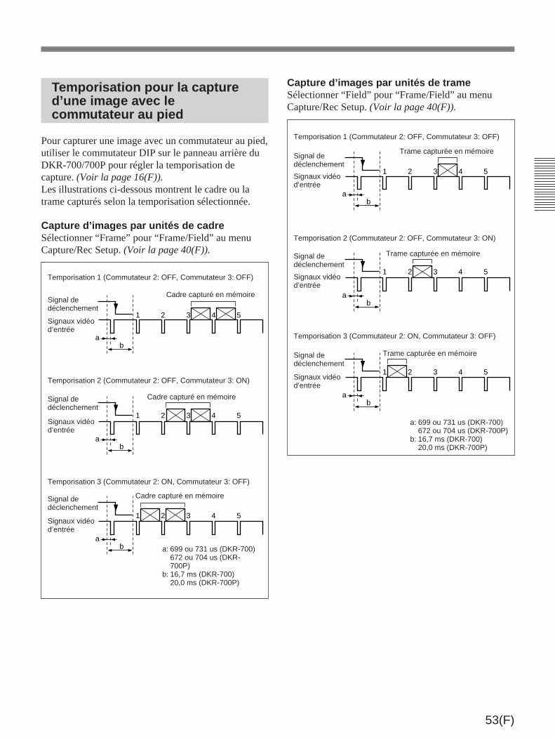
53(F)
Temporisation pour la captured’une image avec lecommutateur au pied
Pour capturer une image avec un commutateur au pied,utiliser le commutateur DIP sur le panneau arrière duDKR-700/700P pour régler la temporisation decapture. (Voir la page 16(F)).Les illustrations ci-dessous montrent le cadre ou latrame capturés selon la temporisation sélectionnée.
Capture d’images par unités de cadreSélectionner “Frame” pour “Frame/Field” au menuCapture/Rec Setup. (Voir la page 40(F)).
Temporisation 1 (Commutateur 2: OFF, Commutateur 3: OFF)
ab
ab
ab
1 2 3 4 5
1 2 3 4 5
1 2 3 4 5
Signal dedéclenchement
Signaux vidéod’entrée
Cadre capturé en mémoire
Temporisation 2 (Commutateur 2: OFF, Commutateur 3: ON)
Signal dedéclenchement
Signaux vidéod’entrée
Cadre capturé en mémoire
Temporisation 3 (Commutateur 2: ON, Commutateur 3: OFF)
Signal dedéclenchement
Signaux vidéod’entrée
Cadre capturé en mémoire
a: 699 ou 731 us (DKR-700)672 ou 704 us (DKR-700P)
b: 16,7 ms (DKR-700)20,0 ms (DKR-700P)
Capture d’images par unités de trameSélectionner “Field” pour “Frame/Field” au menuCapture/Rec Setup. (Voir la page 40(F)).
ab
ab
ab
1 2 3 4 5
1 2 3 4 5
1 2 3 4 5
Temporisation 1 (Commutateur 2: OFF, Commutateur 3: OFF)
Signal dedéclenchement
Signaux vidéod’entrée
Trame capturée en mémoire
Temporisation 2 (Commutateur 2: OFF, Commutateur 3: ON)
Signal dedéclenchement
Signaux vidéod’entrée
Trame capturée en mémoire
Temporisation 3 (Commutateur 2: ON, Commutateur 3: OFF)
Signal dedéclenchement
Signaux vidéod’entrée
Trame capturée en mémoire
a: 699 ou 731 us (DKR-700)672 ou 704 us (DKR-700P)
b: 16,7 ms (DKR-700)20,0 ms (DKR-700P)

Sony Corporation Printed in Japan