Embed Size (px)
Citation preview

Digital Signal Processing

Digital Signal Processing
Concepts and Applications
Bernard Mulgrew, Peter Grant and John Thompson
Department of Electronics and Electrical Engineering The University of Edinburgh

© Bernard Mulgrew, Peter M. Grant and John S. Thompson 1999
All rights reserved. No reproduction, copy or transmission of this publication may be made without written permission.
No paragraph of this publication may be reproduced, copied or transmitted save with written permission or in accordance with the provisions of the Copyright, Designs and Patents Act 1988, or under the terms of any licence permitting limited copying issued by the Copyright Licensing Agency, 90 Tottenham Court Road, London WIP 9HE.
Any person who does any unauthorised act in relation to this publication may be liable to criminal prosecution and civil claims for damages.
The authors have asserted their right to be identified as the authors of this work in accordance with the Copyright, Designs and Patents Act 1988.
First published 1999 by MACMILLAN PRESS LTD Houndmills, Basingstoke, Hampshire RG21 6XS and London Companies and representatives throughout the world
A catalogue record for this book is available from the British Library.
This book is printed on paper suitable for recycling and made from fully managed and sustained forest sources.
10 9 8 7 6 5 4 3 2 1 08 07 06 05 04 03 02 01 00 99
ISBN 978-0-333-74531-1 ISBN 978-1-349-14944-5 (eBook) DOI 10.1007/978-1-349-14944-5

Contents
Preface, x Acknowledgements, xii Abbreviations, xiii Principal symbols, xvi Special functions, xx Introduction, xxi
1 Signal representation and system response, 1 1.1 Introduction, 1 1.2 Signal classification, 3
1.2.1 Energy signals, 3 1.2.2 Power signals, 4
1.3 Fourier series, 5 1.4 The Fourier transform, 13 1.5 Laplace transform, 18 1.6 Transform analysis oflinear systems, 21
1.6.1 Superposition, 21 1.6.2 Linear ordinary differential equations, 22 1.6.3 Response of linear system to a periodic input, 23 1.6.4 General approach, 26
1.7 Transfer function, 27 1.8 Summary, 30 1.9 Problems, 30
2 Time-domain description and convolution, 33 2.1 Introduction, 33 2.2 The impulse response, 33
2.2.1 The impulse, 34 2.2.2 Signal representation, 35 2.2.3 System response to an impulse, 36
2.3 Convolution, 39 2.4 Properties of convolution, 45
2.4.1 Time delay, 47 2.5 Summary, 53 2.6 Problems, 53

vi Contents
3 Transfer function and system characterisation, 56 3.1 Introduction, 56 3.2 Transfer function, poles and zeros, 56 3.3 Transfer function and frequency response, 58
3.3.1 Frequency response from pole/zero diagram, 59 3.3.2 Fourier transform of periodic signals, 61 3.3.3 Measurement offrequency response, 64 3.3.4 Bode plots, 65 3.3.5 Fourier and Laplace, 69
3.4 Transfer function and impulse response, 71 3.5 Time-domain response of first and second order systems, 73
3.5.1 First order systems, 74 3.5.2 Second order systems, 75
3.6 Rise time and bandwidth, 79 3.7 Summary, 81 3.8 Problems, 82
4 Sampled data systems and the z-transform, 85 4.1 Introduction, 85 4.2 Sampled data systems and aliasing, 89
4.2.1 Sampling theorem - the Nyquist criterion, 98 4.2.2 Practical sampled data systems, 98
4.3 The z-transform, 99 4.3.1 The inverse z-transform, 103 4.3.2 Delay theorem, 105
4.4 Digital filters and discrete convolution, 106 4.4.1 Discrete convolution, 109
4.5 Poles and stability, 112 4.6 Frequency response of a digital filter, 113 4.7 Example of a complete system, 117 4.8 Summary, 122 4.9 Problems, 123
5 Infinite impulse response digital filters, 126 5.1 Introduction, 126 5.2 Analogue prototype filters, 127
5.2.1 Introduction, 127 5.2.2 Butterworth prototype polynomials, 128 5.2.3 Chebyshev prototype polynomials, 130
5.3 Digital filter structures, 132 5.3.1 Introduction, 132 5.3.2 The canonicalform, 133 5.3.3 Parallel and cascade realisations, 136
5.4 Filter design methods, 137 5.4.1 Introduction, 137 5.4.2 The bilinear z-transform, 138
5.4.3 Filter transformation, 143 5.5 Finite precision effects, 145
5.5.1 Filter coefficient quantisation errors, 145 5.5.2 Limit cycles, 147 5.5.3 IIRfilter hardware, 147
5.6 Summary, 148 5.7 Problems, 148
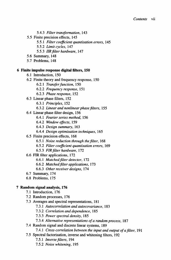
6 Finite impulse response digital filters, 150 6.1 Introduction, 150 6.2 Finite theory and frequency response, 150
6.2.1 Transfer junction, 150 6.2.2 Frequency response, 151 6.2.3 Phase response, 152
6.3 Linear phase filters, 152 6.3.1 Principles, 152 6.3.2 Linear and nonlinear phase filters, 155
6.4 Linear phase filter design, 156 6.4.1 Fourier series method, 156 6.4.2 Window effects, 159 6.4.3 Design summary, 163 6.4.4 Design optimisation techniques, 165
6.5 Finite precision effects, 168 6.5.1 Noise reduction through the filter, 168 6.5.2 Filter coefficient quantisation errors, 169 6.5.3 FIRfilter hardware, 172
6.6 FIR filter applications, 172 6.6.1 Matched filter detector, 172 6.6.2 Matched filter applications, 173 6.6.3 Other receiver designs, 174
6.7 Summary, 174 6.8 Problems, 175
7 Random signal analysis, 176 7.1 Introduction, 176 7.2 Random processes, 176 7.3 Averages and spectral representations, 181
7.3.1 Autocorrelation and autocovariance, 183 7.3.2 Correlation and dependence, 185 7.3.3 Power spectral density, 185 7.3.4 Alternative representations of a random process, 187
7.4 Random signal and discrete linear systems, 189
Contents Vll
7.4.1 Cross-correlation between the input and output of a filter, 191 7.5 Spectral factorisation, inverse and whitening filters, 192
7.5.1 Inverse filters, 194 7.5.2 Noise whitening, 195

Vlll Contents
7.5.3 Cross-correlation between two filter outputs, 196 7.6 Filter noise calculations, 197
7.6.1 Quantisation noise, 198 7.6.2 Dynamic range, 200
7.7 Summary, 203 7.8 Problems, 203
8 Adaptive filters, 206 8.1 Introduction, 206 8.2 Wiener filters, 207
8.2.1 Wiener FIR filter, 208 8.2.2 Application to channel equalisation, 211
8.3 Algorithms for adaptive filtering, 215 8.3.1 Recursive least squares, 217 8.3.2 Stochastic gradient methods, 219 8.3.3 A comparison of algorithms, 227
8.4 Applications, 230 8.4.1 Adaptive line enhancement, 231 8.4.2 Adaptive tone suppression, 233 8.4.3 Noise whitening, 233 8.4.4 Echo cancellation, 234 8.4.5 Channel equalisation, 235
8.5 Summary, 238 8.6 Problems, 238
9 The Fourier transform and spectral analysis, 240 9.1 Development of the discrete Fourier transform, 240
9.1.1 The continuous Fourier transform, 240 9.1.2 Fourier transform of a finite length data record, 241 9.1.3 Definition of the DFT, 243 9.1.4 Properties of the DFT, 245
9.2 Computation of the discrete Fourier transform, 246 9.2.1 DFT matrix coefficient values, 246 9.2.2 Matrixformulation of the DFT, 246 9.2.3 Analogiesfor the DFT, 251
9.3 Resolution and window responses, 253 9.3.1 Resolution, 253 9.3.2 Leakage effects, 253 9.3.3 The rectangular window, 254 9.3.4 Hanning window, 257 9.3.5 Hamming window, 259 9.3.6 The Dolph-Chebyshev window, 259 9.3.7 Window comparisons, 261
9.4 Fundamentals of spectral analysis, 262 9.5 Classical spectral analysis, 264 9.6 Modem spectral analysis, 267

9.6.1 Introduction to parametric techniques, 267 9.6.2 Autoregressive spectrum analysis, 268
9.7 Comparison of spectral analysis techniques, 272 9.8 Application of AR techniques in speech coders, 273 9.9 Summary, 276 9.10 Problems, 276
10 The fast Fourier transform, 278 10.1 Introduction, 278 10.2 Partitioning of the DFT into two half-size matrices, 278 10.3 Radix-2 FFT, 284
10.3.1 Decimation-in-time algorithm, 284 10.3.2 Decimation-in-frequency algorithm, 288
lOA Implementation considerations, 288 1004.1 Complex multiplier hardware, 289 1004.2 Alternative radix arithmetic approaches, 289 1004.3 Real valued data, 290 100404 Inverse transforms, 293
10.5 Applications, 294 10.6 Summary, 297 10.7 Problems, 297
11 Multirate signal processing, 299 11.1 Introduction, 299 11.2 Decimation, interpolation, imaging and aliasing, 300
11.2.1 Decimation, 303 11.2.2 Bandpass sampling, 306 11.2.3 Interpolation, 310
11.3 Applications of multirate systems, 311 11.3.1 Transmultiplexers, 311 11.3.2 Analysis and synthesis filterbanks, 311 11.3.3 Filterbank design approaches, 314
1104 Audio and speech processing, 319 1104.1 Speech and image signal coding, 321
11.5 Summary, 325 11.6 Problems, 325
Appendix A - Matrix theory revision, 327 Appendix B - Signal transforms, 330 Solutions to self assessment questions, 332 Bibliography, 348 Index, 354
Contents ix
Preface
Digital signal processing (DSP) provides a rapidly advancing portfolio of filtering and estimating techniques or algorithms which are used in signal analysis and processing. Significant current applications are in the development of mobile communications equipment, particularly for personal use and design of sophisticated radar systems. The aim of this book is to provide an introduction to the fundamental DSP operations of filtering, estimation and signal analysis as used in signal processing.
Most of the chapters include substantive numerical examples to illustrate the material developed, as well as self assessment questions which have been designed to help readers aid their comprehension of this material. All the chapters conclude with further problem questions for the student.
Chapters 1 to 3 cover basic analogue signal theory as a prerequisite to this DSP text. Chapter 4 extends these concepts to sampled-data systems and here discrete convolution is introduced. Chapters 5 and 6 explore digital filters, both infinite and finite impulse response, which implement the convolution operation and include both analytical design and software optimisation techniques. The two chapters conclude with a brief discussion on the problems of finite precision arithmetic. Chapters 7 and 8 introduce, at a more mathematical level, the concept of random signals, correlation and spectral density. Chapter 8 covers adaptive or self learning filters which alter their characteristics dependent on the signal scenario which is present. They find widespread application in communications systems as equalisers and echo cancellers. The final three chapters deal with spectral analysis techniques. Chapter 9 covers the discrete Fourier transform (DFT), its derivation and the design of DFT processors. This chapter then investigates the application of DFT processors in classical spectrum analysis equipment before introducing the modern analysers which are based on the adaptive filter technique of Chapter 8. Chapter 10 deals with the fast Fourier transform which is the most widely applied implementation of the DFT processing function. Chapter 11 introduces multirate techniques to extend the capabilities of these analysers to speech and image processing applications.
With this balance between signal theory, processor design and systems applications we hope that this text will be useful both in academia and in the rapidly growing commercial signal processing community. Advanced DSP is of fundamental importance in implementing many high performance systems such as personal communications and radar.
To aid the class instructor, the authors can provide a printed set of outline solutions to the end-of-chapter problems and these are available via the WWW on password access. MATLABTM source code is also provided on an open access basis to assist the

Preface Xl
instructor with presentation of the material and the student in understanding of the material. In general the source code provides a computer animation of some of the figures in the book. For example the m-file Ilfig1_ 4.m" contains MATLAB code which produces an animation of the complex phasor of Figure 1.4. These are identified within the text by the g symbol. These software and solutions to problems are available via the menu at the Edinburgh WWW server address: http://www.ee.ed.ac.ukrpmg/SIGPRO/index.htmi. Subsequent corrections to this text will also be available at the same WWW address.
Edinburgh May 1998
Bernard Mulgrew, Peter Grant and John Thompson

Acknowledgements
Parts of this book have been developed from BEng, MEng, MSc and industrial training courses provided by the Department of Electronics and Electrical Engineering at the University of Edinburgh. These courses were also taught by Professor Colin Cowan and Dr James Dripps, and we acknowledge their contribution to the initial shaping of these courses which is reflected in the book's content and structure. We are grateful to Professor Cowan for having provided a draft version of Chapter 5 and Dr Dripps for having provided a draft version of parts of Chapter 9 and for assistance with many of the problem solutions. We are also grateful to Dr Ian Glover at the University of Bradford and Prentice-Hall for permission to include the material on bandpass sampling within Chapter 11, and to the lEE for permission to reproduce Figure 9.22.
We would like to thank all those other colleagues at the University of Edinburgh who have provided detailed comments on sections of this text. Thanks must go to the many students who have read and commented on earlier versions of this material and helped to refine the end-of-chapter problems, particularly to Miss Oh who generated the initial version of many of the diagrams. We also gratefully acknowledge the generous assistance of Dr Jonathon Chambers of Imperial College in carefully reviewing and editing this text. In addition we acknowledge the assistance of Philip Yorke at Chartwell Bratt publishing and training in encouraging us to develop, in the 1980s, the preliminary version of this material.
Special thanks are due to Joan Burton, Liz Paterson and Diane Armstrong for their perseverance over several years in typing the many versions of the individual chapters, as they have evolved into their current form. We also acknowledge Bruce Hassall's generous assistance with the preparation of the final version of the text in the appropriate typefont and text format.
Finally we must thank our respective families: Fiona and Maeve; Marjory, Lindsay and Jenny; and Nadine - for the considerable time that we required to prepare this book and the associated WWW supporting material.
Bernard Mulgrew, Peter Grant and John Thompson

Abbreviations
AC ACF AID ADPCM AGC AM AR
BLMS BP BPF BS
CD CDMA CELP CMOS COFDM
D/A DC DCT DFS DFT DIP DIT DM DPCM DPSK DSB DSP DTFT
ESD
Alternating current (implying sinusoidal signal) Autocorrelation function Analogue to digital (converter) Adaptive DPCM Automatic gain control Amplitude modulation Autoregressive
Block least mean squares Bandpass Bandpass filter Bandstop
Compact disc Code division mUltiple access Codebook of excited linear prediction Complementary metal oxide silicon (transistor) Coded orthogonal frequency-division multiplex
Digital to analogue (converter) Direct current (implying a 0 Hz component) Discrete cosine transform Discrete Fourier series Discrete Fourier transform Decimation in frequency Decimation in time Delta modulation Differential pulse code modulation Differential phase shift keying Double sideband Digital signal processing Discrete-time Fourier transform
Energy spectral density
XIV Abbreviations
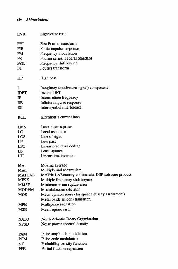
EVR Eigenvalue ratio
FFT Fast Fourier transfonn FIR Finite impulse response FM Frequency modulation FS Fourier series; Federal Standard FSK Frequency shift keying FT Fourier transfonn
HP High pass
I IDFT IF IIR lSI
KCL
LMS LO LOS LP LPC LS LTI
MA MAC MATLAB MFSK MMSE MODEM MOS
MPE MSE
NATO NPSD
PAM PCM pdf PFE
Imaginary (quadrature signal) component Inverse DFT Intennediate frequency Infinite impulse response Inter-symbol interference
Kirchhoff's current laws
Least mean squares Local oscillator Line of sight Low pass Linear predictive coding Least squares Linear time invariant
Moving average Multiply and accumulate MATrix LABoratory commercial DSP software product Multiple frequency shift keying Minimum mean square error Modulator/demodulator Mean opinion score (for speech quality assessment) Metal oxide silicon (transistor) Multipulse excitation Mean square error
North Atlantic Treaty Organisation Noise power spectral density
Pulse amplitude modulation Pulse code modulation Probability density function Partial fraction expansion

Abbreviations xv
PLL Phase locked loop PM Phase modulation PN Pseudo-noise PO Percentage overshoot PPM Pulse position modulation PR Perfect reconstruction PSD Power spectral density PSK Phase shift keying PWM Pulse width modulation
Q Quantiser
R Real (in-phase signal) component RAM Random access memory ROM Read only memory RLS Recursive least squares RMS Root mean square
SAQ Self assessment question SBC Sub-band coder sa Stochastic gradient SIR Sample and hold SNR Signal-to-noise ratio
TDM Time division multiplex THD Total harmonic distortion
VLSI Very large scale integrated (circuit)
WWW World Wide Web
ZOH Zero order hold

Principal symbols
a Qi
A An A(k)
bi B Bn B(k)
d
e e(n) E
10 11 i2 hdB Ib Ie IH fL lLO Is Fm(z)
tap weight vector digital filter weight coefficient value for tap i A-law PCM compander constant nth trigonometric Fourier component kth real Fourier coefficient
digital filter recursive weight coefficient value for tap i signal bandwidth in Hz nth trigonometric Fourier component kth imaginary (real valued) Fourier coefficient
FIR filter coefficient value windowed coefficient value constant, capacitance (Farads) Chebyshev polynomial of order n
lag
error vector scalar error signal at data sample n energy of signal x(t)
centre frequency passband cut-off frequency stopband edge frequency half power bandwidth bit rate centre frequency highest frequency component lowest frequency component local oscillator frequency sample frequency (in Hz) z-plane reconstruction filter m response
g(t) g(kTs) g(kTs) G Gp
h(n) h(n) h(t) HnIH(s) HA(m) HD(m) H(s) H(z) H(m)
lo[ ]
k K
L L(m)
M
n N N
No
P PI p(v) P
q Q
ryx
Ryy
R
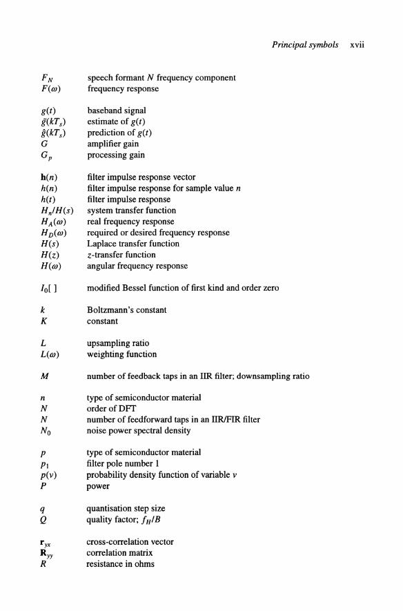
speech formant N frequency component frequency response
baseband signal estimate of g(t) prediction of g(t) amplifier gain processing gain
filter impulse response vector filter impulse response for sample value n filter impulse response system transfer function real frequency response required or desired frequency response Laplace transfer function z-transfer function angular frequency response
Principal symbols xvii
modified Bessel function of first kind and order zero
Boltzmann's constant constant
upsampling ratio weighting function
number of feedback taps in an IIR filter; downsampling ratio
type of semiconductor material orderofDFf number of feedforward taps in an IIRlFIR filter noise power spectral density
type of semiconductor material filter pole number 1 probability density function of variable v power
quantisation step size quality factor; fHIB
cross-correlation vector correlation matrix resistance in ohms

XVlll Principal symbols
RD RC
t /).t
x x(n) fen)
Xn X(f/OJ) IX(f/OJ)1 X(k) X(s)
yen)
YD(n) y/(n)
a
p
dynamic range resistor-capacitor time constant 'Cc
Laplace variable power spectral density
time sample period
eigenvector of autocorrelation matrix information signal voltage waveform of symbol i
FIR filterlDFf window or weight coefficient n kth value of the N roots of unity DFf of window function
vector x sampled input signal estimate of input signal complex Fourier coefficient Fourier (voltage) spectrum of x(n) Fourier amplitude spectrum DFf output value for bin or sample number k Laplace transform of x(t)
processed output signal decimated signal interpolated signal
filter zero number n
attenuation; forgetting factor or window taper
constant
Dirac delta impulse function impulse train voltage difference gradient vector
error voltage; Chebyshev design parameter
TJ TJ(n)
p p(n)
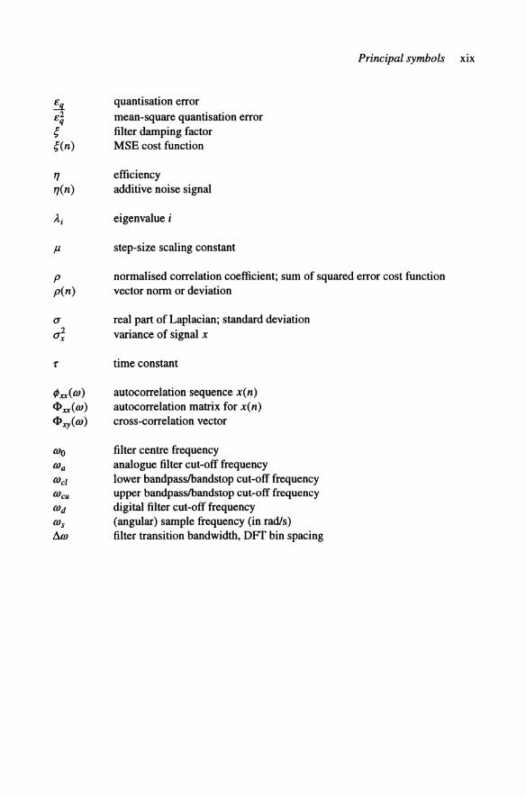
quantisation error mean-square quantisation error filter damping factor MSE cost function
efficiency additive noise signal
eigenvalue i
step-size scaling constant
Principal symbols XIX
normalised correlation coefficient; sum of squared error cost function vector norm or deviation
real part of Laplacian; standard deviation variance of signal x
time constant
autocorrelation sequence x(n) autocorrelation matrix for x(n) cross-correlation vector
filter centre frequency analogue filter cut-off frequency lower bandpasslbandstop cut-off frequency upper bandpasslbandstop cut-off frequency digital filter cut-off frequency (angular) sample frequency (in rad/s) filter transition bandwidth, DFf bin spacing

Special functions
E[ ] [ , ] ( ) * • a F[,] g
f(.) L[,] 9t sa (x) sgn (x) sinc (x) u(t) Z-I
Z
statistical expectation operator scalar product time average convolution operation complex conjugate of a Fourier transform operator operator corresponding to imaginary part of ...
integer part of ...
Laplace transform operator operator corresponding to real part of ... sampling function signum (sign) function sinc function unit step function inverse z transform z transform

Introduction
Real life signals are generally continuous in time and analogue, i.e. they exist at all time instances and can assume any value, within a predefined range, at these time instances. There are many kinds of analogue signals appearing in nature:
Electrical signals: voltages, currents, electric and magnetic fields. • Acoustic signals: mechanical vibrations, sound waves. • Mechanical signals: displacements, angular motion, velocities, forces,
moments, pressures.
Acoustic signals such as sound waves are converted to electrical voltages or currents by sensors or transducers, (i.e. a microphone) in order for them to be processed in an electronic system. Analogue processing involves linear operations such as amplification, filtering, integration and differentiation, as well as various forms of nonlinear processing such as squaring or rectification. This text does not cover the field of nonlinear signal processing, but, in practice, saturation in amplifiers or mixing of signals often introduces nonlinearities. Limitations of practical analogue processing operations are:
Restricted accuracy. Sensitivity to noise.
• Restricted dynamic range. Poor repeatability due to component variations with time, temperature, etc.
• Inflexibility to alter or adjust the processing functions. • Problem in implementing accurate nonlinear and time-varying operations. • Limited speed of operation. • High cost of storage for analogue waveforms.
However, in the 1970s, analogue signal processing in the form of surface acoustic wave and charge-coupled sampled-data devices delivered very sophisticated matched filter and correlator parts which were widely used in military equipment. At this time it was not possible to match the analogue speed/performance capability with digital devices so the accuracy of analogue processors was severely limited. The initial implementations of Dolby noise reduction systems also employed analogue filter techniques and the early Y.21-V.29 data modems, for transmission of digital data over telephone lines, used exclusively analogue filters and modulators.

XXll Introduction
Digital signal processing (DSP) is achieved by sampling the analogue signal at regular intervals and representing each of these sample values with a binary number. These are subsequently passed to a specialised digital processor to perform numerical or computational operations on these signals. Operations in digital signal processing systems encompass additions, multiplications, data transfers, logical operations and can be extended to implementation of complex matrix manipulations. The essential operations of many DSP systems include:
Converting analogue signals into a sequence of digital binary numbers, which requires both sampling and analogue-to-digital (NO) conversion.
• Performing numerical manipulations, predominantly multiplications, on the digital information data stream. Converting the digital information back to analogue signal, by digital-toanalogue (D/A) conversion and filtering.
The basic components of the digital processor, which is equivalent to the analogue processing function, is considered later in Chapter 4. The DSP function is generally described as an algorithm or program which defines the in-built arithmetic operations. DSP is in fact an extension of the conventional microprocessor function except that a fast multiplier is added as a hardware accelerator element.
The main attraction of digital processors is that their accuracy, which is controlled by the quantisation step size or word length employed in the NO converter, is extendable only at the cost of greater complexity for the ensuing processing operations, i.e. additions and multiplications. However, floating-point number representations permit the accuracy to be maintained over a wide dynamic range. Further, digital processors are generally repeatable and much less sensitive to noise than analogue processors as they are dealing with binary symbols and the processed outputs must always possess binary values. The microelectronics industry has been reducing continuously silicon VLSI circuit geometrics and hence improving the speed, complexity and storage capacity. The feature size in the 1970s was 5,um while in the year 2000 we will be designing VLSI circuits with 0.18,um feature sizes and single chip complexities of 40 M individual transistors, and by the year 2010 0.7,um feature size circuits are predicted to have 3 GHz clock rates.
VLSI permits the design of application specific integrated circuits with exceptional cost/performance capabilities to execute sophisticated DSP processing functions. Current developments in microelectronics are delivering an order of magnitude increase in processor operating speed, coupled with a 30-fold reduction in power consumption, every eight years.
Some of the key benefits which derive from digital signal processing are:
Efficient implementation of linear phase filters for communication and radar receiver design.
• Easy realisation of Fourier transform processors for signal analysis. Possibility of implementing complicated processing functions involving matrix manipulations.

Introduction xxiii
These advances in DSP, complexity and functionality over analogue signal processing are not obtained without some penalties. High accuracy, high speed AID and D/A conversion hardware is expensive and it can lead to noise and distortion problems. We always require bandlimiting filters before the sampling function and this introduces some loss of information. For some applications, e.g. RF signals, digital processors cannot achieve the necessary high speed sampling requirements. Even with these drawbacks the use of DSP is becoming ubiquitous, partly because of the 40% per year cumulative growth of the DSP since 1988, with predicted market sales of 6,000,000,000 dollars in 2000. The generic application areas are:
Speech and audio: noise reduction (Dolby), coding, compression (MPEG), recognition, speech synthesis.
Music: recording, playback and mixing, synthesis of digital music, CD players.
Telephony: speech, data and video transmission by wire, radio or optical fibre.
Radio: digital modulators and modems for cellular telephony.
Signal analysis: spectrum estimation, parameter estimation, signal modelling and classification.
Instrumentation: signal generation, filtering, signal parameter measurement.
Image processing: 2-D filtering, enhancement, coding, compression, pattern recognition.
Multimedia: generation, storage and transmission of sound, motion pictures, digital TV, HDTV, DVD, MPEG, video conferencing, satellite TV.
Radar: filtering, target detection, position and velocity estimation, tracking, imaging, direction finding, identification.
Sonar: as for radar but also for use in acoustic media such as the sea.
Control: servomechanisms, automatic pilots, chemical plant control.
Biomedical: analysis, diagnosis, patient monitoring, preventive health care, telemedicine.
Transport: vehicle control (braking, engine management) and vehicle speed measurement.
Navigation: Accurate position determination, global positioning, map display.

XXIV Introduction
The key attraction of DSP devices is that their in-built programmability allows one standard part to be applied to most of these processing functions by changing the stored program or instruction set.
In terms of specific uses, the modem car has many tens of processors attached to sensors for fuel injection, engine management, passenger compartment climate control, braking system protection, detection of component failure, etc. In fact a major part of the modem automobile comprises electronics rather than mechanical engineering. Modem mobile and cellular telephone systems rely on advanced signal processing to detect and decode the received signals, to minimise received errors, to control the mobile transmissions, to enhance battery life, etc. The TV set and new set-top boxes contain a large number of DSP chips to detect the low power signals received and to decompress the video traffic efficiently.
In the late 1990s there are a tremendous number of applications for DSP and, in the future, we confidently expect these to increase as the continuous growth in processor power and novel algorithm development unlocks even more sophisticated processing algorithms which cannot be contemplated today. DSP is thus now firmly entrenched in the consumer marketplace.