Embed Size (px)
Citation preview
DIGITAL READOUT AND CONTROL SYSTEM FOR A 64-INCH (1.63-m) SCATTERING CHAMBER
by Lawrence P. Mddson
Lewis Research Center i
NATIONAL AERONAUTICS A N D SPACE A D M I N I S T R A T I O N WASHINGTON, D. C. J A N U A R Y 1 9 6 8
I
https://ntrs.nasa.gov/search.jsp?R=19680004549 2018-09-01T22:12:22+00:00Z
I
TECH LIBRARY KAFB, NM
I111111 11111 Ill11 lllll lllll lllll11111llll Ill
DIGITAL READOUT AND CONTROL SYSTEM FOR A 64-INCH (1.63-m)
SCATTERING CHAMBER
By Lawrence P. Madson
Lewis Research Center Cleveland, Ohio
NATIONAL AERONAUTICS AND SPACE ADMINISTRATION
For sale by the Clearinghouse for Federal Scientific and Technical Information Springfield, Virginia 22151 - CFSTl price $3.00
-
1 1 1 1 1111I II 11111111III 11111 II 111111II Ill II 1111II Ill I I I 11111III I II I111111 II I I l l 1111111I I I II I I I I IIIIII I111 1111111 1111111 1 1 1 1 I I I l l
I
DIGITAL READOUT AND CONTROL SYSTEM FOR A 64-INCH (1.63-m)
SCAlTERING CHAMBER
by Lawrence P. Madson
Lewis Research Center
SUMMARY
This report describes an automatic digital position control system for scattering chamber now in use with the 60-inch (1. 52-m) cyclotron at the Lewis Research Center. It features programmed remote control of detector positions with accuracies of a. 03 de- gree for these positions. The system has been in continuous operation for a period of 6 months and has resulted in a 20 percent saving in experiment running time.
INTRODUCTION
A 64-inch (1.63-m) scattering chamber has been in operation with the 60-inch (1. 52-m) cyclotron at the Lewis Research Center since June 1963. ber has two movable a rms to hold the detectors and a movable table to hold the target. To get meaningful data from scattering experiments, the detector and target positions with relation to the beam must be accurately known and a method must be provided to po- sition them from a remote-control room.
w a s converted to an analog voltage by means of a potentiometer 'and read by a digital voitmeter. The accuracy of this system was a. 1 degree.
After a year of operation, it became apparent that a more accurate readout and con- trol system was required. The analog system was also inconvenient to use. It had to be recalibrated for each experiment owing to zero shift and nonlinearities in the potentiom- eter used, and it did not lend itself easily to automatic operation.
The readout and control system described in this report is an all-digital system. Its features are high resolution and accuracy for the detector arm and target table posi- tions and simple, efficient operation. The accuracy of the digital system is i-O.03degree.
The scattering cham-
The original readout and control system used analog techniques. Angular position
Stepping-motor drive is used to aid in setup and it provides simple step-by-step position control. Optical incremental position transducers are used for position readout to give the angular position directly in degrees, and a zero -indicated angle not dependent on me - chanical position.
The digital readout and control system can be easily automated to speed data acquisi- tion. The angle data as well as the experimental data is in digital form. This permits easy integration into a digital data-acquisition system. Automatic positioning of the de - tector arms and target table is achieved by using an input of either punched paper tape or keyboard entry.
tember 1966, and its use has resulted in a 20 percent saving in experiment running time. The digital readout and control system has been operating satisfactorily since Sep-
General Descr ipt ion of System
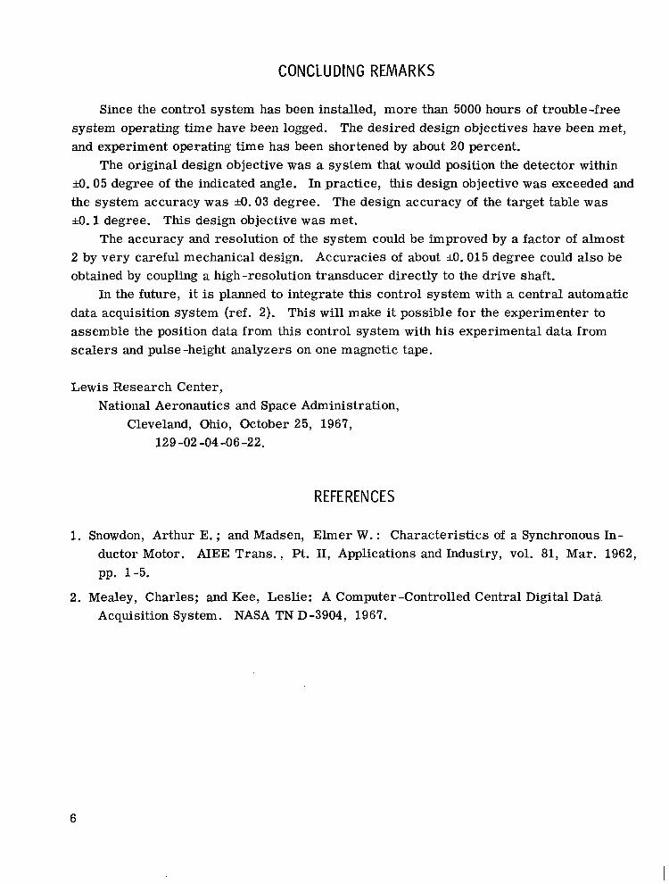
The 64-inch (1.63-m) scattering chamber at the Lewis Research Center is used for nuclear research in conjunction with the 60-inch (1. 52-m) cyclotron. It consists of an aluminum tank with an inside diameter of 64 inches (1.63-m). An interior view of the chamber (fig. 1) shows the two detector a rms and the target table. The detector a rms a r e driven by a stepping motor and ring gear, and the target table is driven by a stepping motor and worm gear. Incremental position transducers for the detector arms a r e driven by the ring gears, and the target-table transducer is directly coupled to the target-table drive shaft. Located near the scattering chamber are the electronics associated with the incremental transducers and the stepping motors. These are amplifiers and direction- sensing electronics for the transducers and a pulse translator and driver for the motors.
The main control console (fig. 2) is located in the control room, which is approxi- mately 300 feet (91 m) from the scattering chamber. Housed in the control console a re the memory registers, digital readout, tape reader, keyboard, and control logic.
SYSTEM OPERATION
Manual
To operate the system manually, the operator selects the desired detector arm o r the target table with a switch. The arm o r table selected can then be moved in either di- rection by operating pushbutton switches located in the control console. Continuous oper- ation of the stepping motor drive occurs when either of the buttons is depressed. To aid in setting a desired position, another mode of operation is provided which allows the
2
operator to move the drive motor one step at a time, each time a direction pushbutton is depressed. The actual position is read directly in degrees on the digital display.
A remote-control station at the scattering chamber is also provided to aid the opera- tor in setting up an experiment. This control station allows manual operation of both de- tector a rms and the target table from the vicinity of the scattering chamber.
Automatic
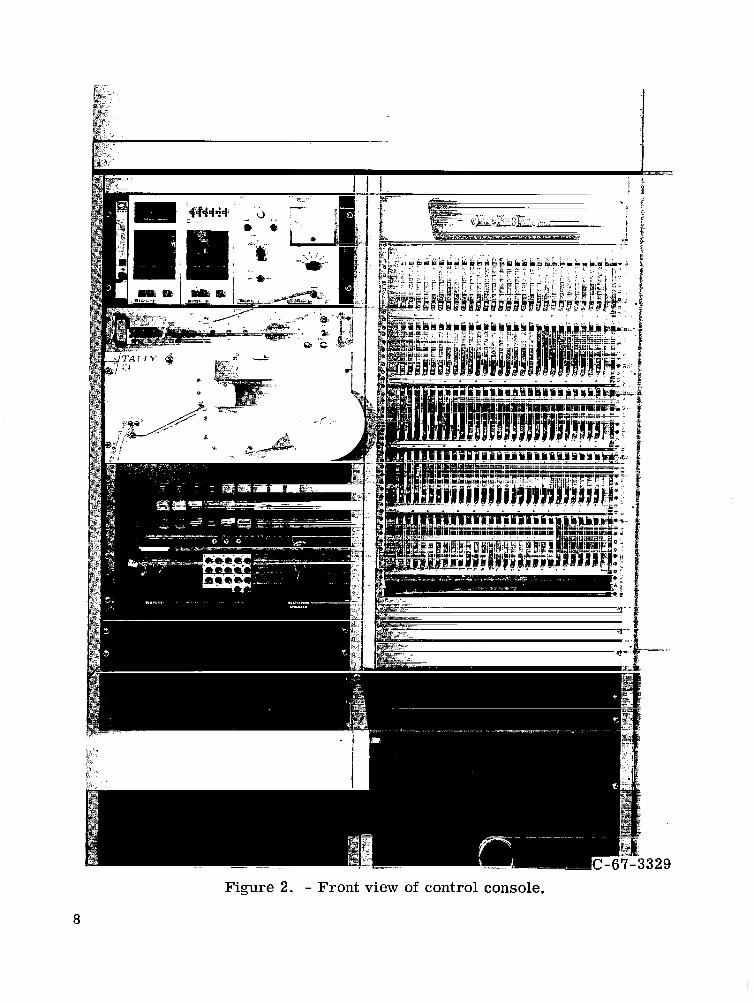
Automatic position control is possible through the use of either the punched paper- tape reader o r the keyboard on the control console. The keyboard'or the tape reader reads the desired position into a binary coded decimal to binary converter and preset position register which is a recirculating shift register that contains the preset position information (fig. 3). The number in this preset register is compared with the actual po- sition of any one of the memory registers in a subtractor. There is a memory register associated with each detector arm and with the target table. The proper memory regis- ter and drive motor a re selected by a flip-flop from the coded information on the paper tape or a key on the keyboard. The output of the subtractor is used to control the speed and direction of the drive motors. When a detector arm is more than 0 . 3 degree from the desired angle, the motor runs at high speed (100 steps/sec). As the arm approaches the desired angle, the motor speed is reduced by a factor of 4 to 25 steps per se~ond. This prevents overshooting the set point.
selected, the detector arm or the target table moves to the desired preset position auto- matically. When paper tape is used as the source input for information in the automatic mode, the only operation required of the operator is to press the start button for each data point and the a rms and table wil l be positioned automatically in sequence, according to any program punched on the tape. When all the positions are reached, a signal is pro- vided to indicate that. positioning is accomplished.
When the desired angle has been entered and the proper motor and register have been
DESIGN PHILOSOPHY
Components and techniques were chosen with special consideration given to a mini- mum hardware requirement and trouble -free operation.
Stepping motors are used to drive the system because they offer several advantages. They offer precise control of the position since they are able to move in small increments one step at a time, starting'and stopping with no overtravel. They a r e direct digital-to- analog converters operating from a pulse input. Being induction motors and having no
3
brushes, they are simple in design. These features make the induction stepping motor an ideal drive motor for a digital-control system.
highly accurate and reliable method of reading increments of arc. They offer a direct digital output which makes them the logical ch0ic.e for a digital control system. Optical encoders are especially reliable because they use no brushes and have no moving electri- cal parts to wear out.
The logic of the control system operates using serial binary arithmetic. This choice was made because this type of arithmetic performs the job with the minimum ofhardware.
Optical incremental shaft encoders were chosen for me readout because they offer a
HARDWARE DESCRIPTION
T r a n s d u c e r s
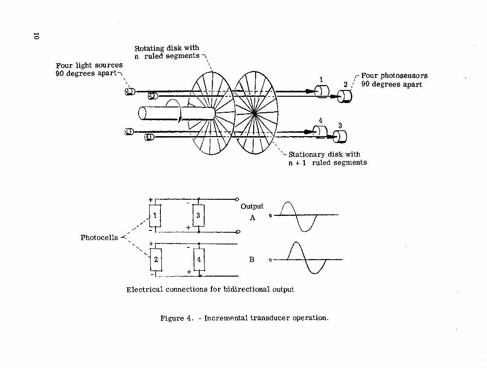
To determine accurately the position of the detector a r m s and the target table, incre- mental optical shaft encoders are' used as position transducers. These encoders with associated logic produce a train of output pulses proportional to the angle of the shaft ro- tation and coded to indicate the direction of the shaft rotation. The principle of operation is shown in figure 4. The transducer has four light sources placed 90 degrees apart with corresponding photosensors. Interposed between the light sources and the sensors are two transparent disks with ruled patterns of alternating opaque and clear sectors. One disk with 900 lines is mounted to the shaft; the other with 901 lines is fixed to the housing. Because the anchored disk has one more line than the rotating disk, a moire pattern is generated. When maximum light is transmitted through one region 180 degrees away, the photosensor illumination is at a minimum. One full revolution of the input shaft causes the moire pattern to rotate 900 times. The output produced by pairing two photosensors that are 180 degrees from each other is a full sine wave. Use of both pairs of photosen- sors gives two sine waves 90 degrees out of phase. If one output is used for a reference signal, the other output is displaced 90 degrees for clockwise rotation and -90 degrees for counterclockwise rotation.
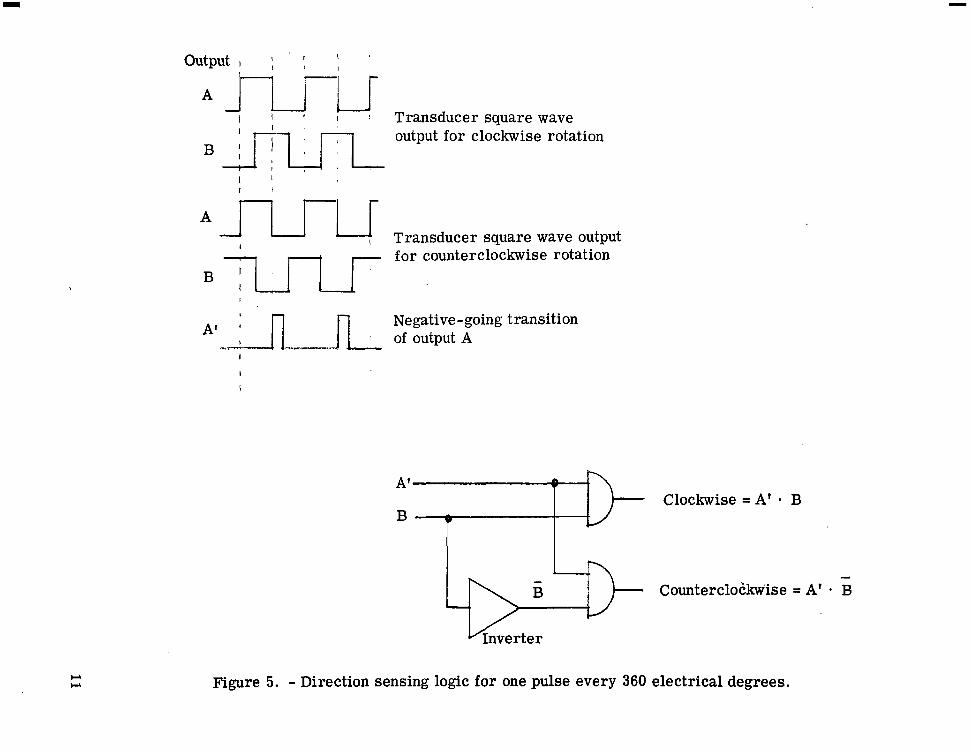
The transducer output signals are first amplified and clipped to produce two square wave signals 90 electrical degrees out of phase. These square wave signals a r e applied to a ldgic circuit that performs the logic operations shown in figure 5. One square wave output is used for a reference and is differentiated by means of a monostable multivibra- tor. This differentiated signal is combined with the other output signal in logic gates, and a bidirectional pulse output is obtained (fig. 5).
Output pulses corresponding to 360, 180, or 90 degrees of electrical rotation can be obtained with proper logic circuity. The position transducers used in this control system
4
produce 900, 1800, or 3600 pulses per revolution of the input shaft, depending on whether a pulse is desired for every 360, 180, or 90 electrical degrees of rotation, respectively. Each of these modes of operation is used in this control system. The resolution is 0.02 degree for each of the detector a rms and 0.1 degree for the target table. This is obtained by proper coupling to the -ring gears.
Memory Registers
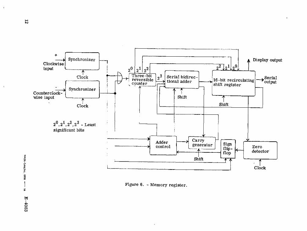
The pulse trains corresponding to the angle and direction of rotation of the transducer shaft are counted and stored as a binary number corresponding to the angular position in degrees. The memory register (fig. 6) consists of a bidirectional ser ia l adder and a 16-bit recirculating shift register with a recirculation rate of 5 kilohertz. The forward and reverse pulse trains are applied to the input synchronizers (fig. 6) which synchronize the pulse with the internal 100-kilohertz clock. The pulses operate the adder control flip-flop, which adds pulses for increasing angles and subtracts pulses for decreasing angles. The input pulses also operate the sign flip-flop, which is positive for increasing angles with clockwise rotation of the transducer shaft starting.from zero and negative for increasing angles with counterclockwise rotation of the transducer shaft starting from
0 1 2 zero. The three least significant bits (2 , 2 , 2 ) of the stored number are counted on a fast, reversible counter to make the actual count rate 40 kilohertz, which is eight times faster than the 5 kilohertz recirculation rate of the shift register. The three least signi- ficant bits are entered into the register in parallel each recirculation cycle, and the
3 15 higher order bits (2 to 2 (fig. 6).
) are then entered serially through the bidirectional adder
Drive Motors
Synchronous inductor stepping motors (ref. 2) are used as drive motors for the con- trol system. The particular version used is a bifilar -wound direct-current stepping motor. The motors move 1.8 degrees per step and are geared down to 0.01 degree per step for the detector a r m s and 0.05 degree per step for the target table. To run the motor, pulses are applied to a translator which generates the proper switching sequence for operating the motor.
5
CONCLUDING REMARKS
Since the control system has been installed, more than 5000 hours of trouble-free system operating time have been logged. The desired design objectives have been met, and experiment operating time has been shortened by about 20 percent.
io. 05 degree of the indicated angle. In ,practice, this design objective was exceeded and the system accuracy was io. 03 degree. The design accuracy of the target table was a. 1 degree. This design objective was met.
The accuracy and resolution of the system could be improved by a factor of almost 2 by very careful mechanical design. Accuracies of about io. 015 degree could also be obtained by coupling a high-resolution transducer directly to the drive shaft.
data acquisition system (ref. 2). This wil l make it possible for the experimenter to assemble the position data from this control system with his experimental data from scalers and pulse -height analyzers on one magnetic tape.
The original design objective was a system that would position the detector within
In the future, it is planned to integrate this control system with a central automatic
Lewis Research Center, National Aeronautics and Space Administration,
Cleveland, Ohio, October 25, 1967, 129 -02 -04 -06 -22.
REFERENCES
1. Snowdon, Arthur E. ; and Madsen, Elmer W. : Characteristics of a Synchronous In- ductor Motor. AIEE Trans. , Pt. 11, Applications and Industry, vol. 81, Mar . 1962, pp. 1-5.
2. Mealey, Charles; and Kee, Leslie: A Computer-Controlled Central Digital Data Acquisition System. NASA TN D-3904, 1967.
6
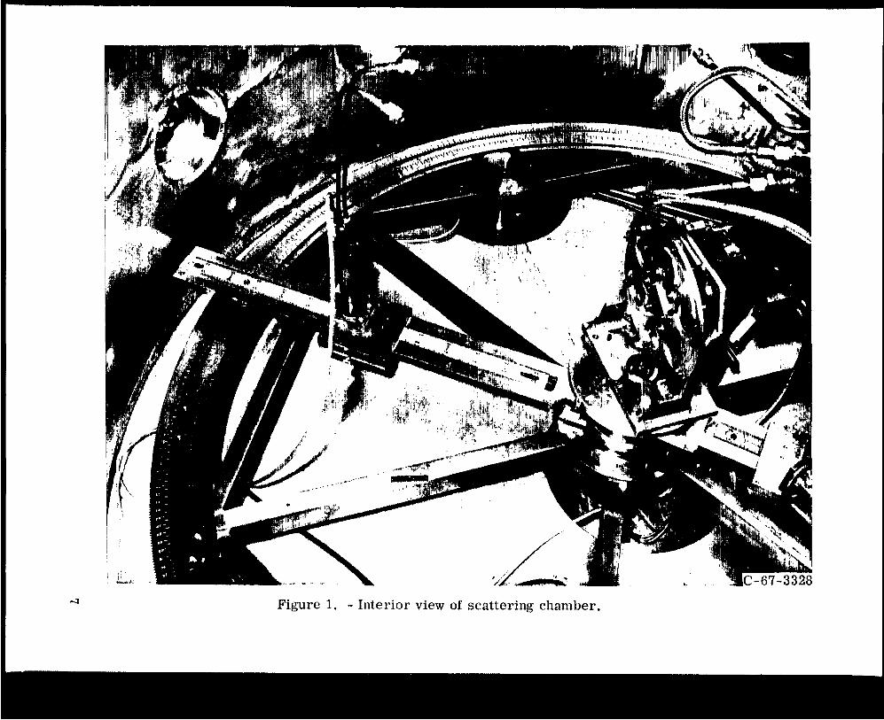
Figure 1. - Interior view of scattering chamber.
1 !
Figure 2. - Front view of control console.
8
Scattering chamber
Transducer
Motor
Control room
I
+ I Memory I-) Subtractor 1
L rx2 * register :
I 1
I
+ I Memory I-) Subtractor 1
L rx2 * register :
I 1
I
I
l i i l ! Y
I Manual control I
position
i I - - Paper tape ' 'or keyboard. L
Figure 3 - Simplified system block diagram (one motor and transducer).
Rotating disk with n ruled segments 7
\ \ Four light sources \
\ r Four photosensors 90 degrees apar t7 \ 90 degrees apart
'L Stationary disk with n + 1 ruled segments
- Photocells <p
Electrical connections for bidirectional output
Figure 4. - Incremental transducer operation.
1 output 1 ; I I I
I ' ! Transducer square wave output for clockwise rotation BJTm,
I ' I I
A u Transducer square wave output I
I )-I ,--- for counterclockwise rotation
Negative - going transition of output A
Clockwise = A' 9 B B
d
Counterclokkwise = A' . B
Figure 5. - Direction sensing logic for one pulse every 360 electrical degrees,
r I I
P 1
Serial bidirec- '
tional adder 16 -bit recirculating shift register
)\
4 I
Serial 'output -
i
2°,21,22,23 - Least I significant bits I
I Clock
I
M I
I Siift
Figure 6. - Memory register.
"Ths aeronautical and space activities of the United States shall be conducted so a to contribute . . . to the expansion of human knowl- edge of phenomena in the atmosphere and space. The Administration shall provide for the widest practicable and appropriate dissemination of information concerning its activities and the results tbereof."
-NATIONAL AERONAUTICS AND SPACE ACT OF 1958
NASA SCIENTIFIC AND TECHNICAL PUBLICATIONS
TECHNICAL REPORTS: Scientific and technical information considered important, complete, and a lasting contribution to existing knowledge.
TECHNICAL NOTES: Information less broad in scope but nevertheless of importance as a contribution to existing knowledge.
TECHNICAL MEMORANDUMS: Information receiving limited distribu- tion because of preliminary data, security classification, or other reasons.
CONTRACTOR REPORTS: Scientific and technical information generated under a NASA contract or grant and considered an important contribution to existing knowledge.
TECHNICAL TRANSLATIONS: Information published in a foreign language considered to merit NASA distribution in English.
SPECIAL PUBLICATIONS: activities. compilations, handbooks, sourcebooks, and special bibliographies.
TECHNOLOGY UTILIZATION PUBLICATIONS: Information on tech- nology used by NASA that may be of particular interest in commercial and other non-aerospace applications. Publications indude Tech Briefs, Technology Utilization Reports and Notes, and Technology Surveys.
Information derived from or of value to NASA Publications include conference proceedings, monographs, data
Details on the availabilify of these publications may be obtained from:
SCIENTIFIC AND TECHNICAL INFORMATION DIVISION
NATIONAL AERONAUTICS AND SPACE ADMINISTRATION
Washington, D.C. 90546