Embed Size (px)
Citation preview
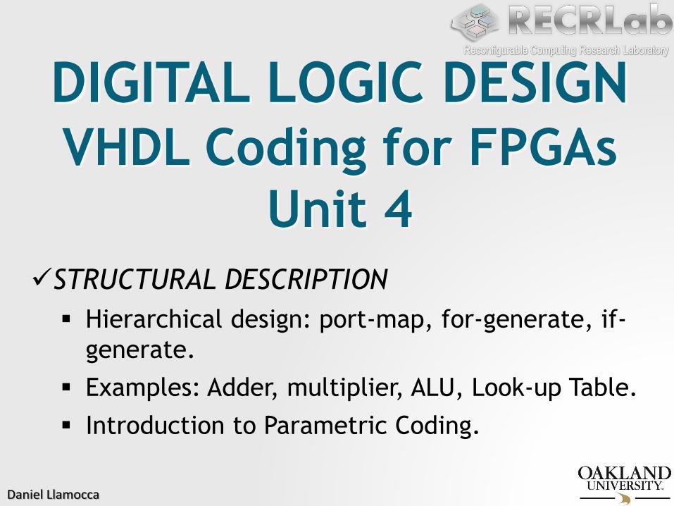
Daniel Llamocca
DIGITAL LOGIC DESIGNVHDL Coding for FPGAs
Unit 4
STRUCTURAL DESCRIPTION
Hierarchical design: port-map, for-generate, if-
generate.
Examples: Adder, multiplier, ALU, Look-up Table.
Introduction to Parametric Coding.

Daniel Llamocca
STRUCTURAL DESCRIPTION
It is the generalization of the Concurrent Description. The circuitsare described via interconnection of its subcircuits. This subcircuitscan be described in concurrent code and/or sequential code.
Example: Multiplexor 2-to-1.
f
b
s
a
0
1
a
b
f
s
This case is trivial, since the interconnection is realised via logicoperators, but nevertheless it is an example of structuraldescription.

Daniel Llamocca
STRUCTURAL DESCRIPTION
Example: 4-to-16 decoder
We can describe thisdecoder in an structuredway based on 2-to-4 decoders.
However, we can alsodescribe the 4-to-16 decoder using the with-select statement.
w2
E
w3
w0
w1
E
w0
w1
E
w0
w1
w0
w1
E
w0
w1
E
w0
w1
E
y0
y1
y2
y3
y4
y5
y6
y7
y8
y9
y10
y11
y12
y13
y14
y15
y0
y1
y2
y3
y0
y1
y2
y3
y0
y1
y2
y3
y0
y1
y2
y3
y0
y1
y2
y3

Daniel Llamocca
STRUCTURAL DESCRIPTION
Example: DLX Processor
In this type of systems, it is best todescribe each component first, then assemble them to make thelarge system.
We do not need to see such largesystem to realise the importance of the Structural Description.
CO
NTRO
LLER
ALU
S1
S2
A
B
REGISTER FILE
C
TEMP
IAR
PC
MAR
MDR
IR
X1
X2

Daniel Llamocca
STRUCTURAL DESCRIPTION
Many systems can be described entirely in one single block: wecan use the behavioral description, and/or concurrent statements(with-select, when-else).
However, it is advisable not to abuse of this technique since itmakes: i) the code less readable, ii) the circuit verification processmore cumbersome, and iii) circuits improvements less evident.
The structural description allows for a hierarchical design: we can ‘see’ the entire circuit as the pieces it is made of, then identifycritical points and/or propose improvements on each piece.
It is always convenient to have basic building blocks from which wecan build more complex circuits. This also allows building block (orsub-system) to be re-used in a different circuit.

Daniel Llamocca
STRUCTURAL DESCRIPTION
Example: 4-bit add/sub for numbers in 2’s complement
FA
x0 y0
c0
s0
FA
x1 y1
c1
s1
FA
x2 y2
c2
s2
c3FA
x3 y3
s3
c4cout cin
overflow
add/sub
add =0sub = 1
The circuit can be described in one single block.
However, it is best to describe the Full Adder as a block in a separate file (full_add.vhd), then use
as many full adders to build the 4-bit adder.
The place where we use and connect as many full
adders as desired, and possibly add extra circuitryis called the ‘top file’ (my_addsub.vhd). This
creates a hierarchy of files in the VHDL project:
FAci
s0
ci+1
x0 y0
full_add.vhd
my_addsub.vhd

Daniel Llamocca
4-bit 2’s complement Adder
Full Adder: VHDL Description (fulladd.vhd):
library ieee;
use ieee.std_logic_1164.all;
entity fulladd is
port ( cin, x, y: in std_logic;
s, cout: out std_logic);
end fulladd;
architecture struct of fulladd is
begin
s <= x xor y xor cin;
cout <= (x and y) or (x and cin) or (y and cin);
end struct;
FAcin
s
cout
x y

Daniel Llamocca
4-bit 2’s complement Adder
Top file (my_addsub.vhd): We need 4 full adders block and extra
logic circuitry.
In order to use thefile ‘fulladd.vhd’
into the top file, weneed to declare it in the top file:
library ieee;
use ieee.std_logic_1164.all;
entity my_addsub is
port ( addsub: in std_logic;
x,y: in std_logic_vector(3 downto 0);
s: out std_logic_vector(3 downto 0);
cout, overflow: out std_logic);
end my_addsub;
architecture struct of my_addsub is
component fulladd
port ( cin, x, y: in std_logic;
s, cout: out std_logic);
end component;
signal c: std_logic_vector(4 downto 0);
signal yt: std_logic_vector(3 downto 0);
begin -- continued on next page
We copy whatis in the entity of full_add.vhd

Daniel Llamocca
4-bit 2’s complement Adder
Here, we:
Insert the required extra circuitry (xor gates and I/O
connections).
Instantiate the full adders and interconnect them (using the
port map statement)
-- continuation from previous page
c(0) <= addsub; cout <= c(4);
overflow <= c(4) xor c(3);
yt(0) <= y(0) xor addsub; yt(1) <= y(1) xor addsub;
yt(2) <= y(2) xor addsub; yt(3) <= y(3) xor addsub;
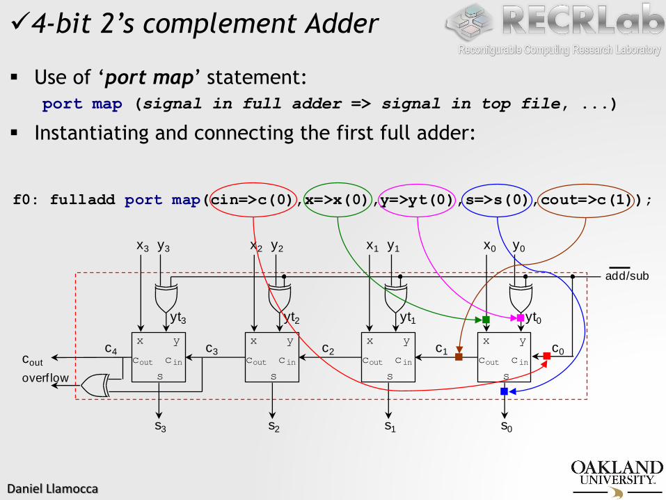
f0: fulladd port map(cin=>c(0),x=>x(0),y=>yt(0),s=>s(0),cout=>c(1));
f1: fulladd port map(cin=>c(1),x=>x(1),y=>yt(1),s=>s(1),cout=>c(2));
f2: fulladd port map(cin=>c(2),x=>x(2),y=>yt(2),s=>s(2),cout=>c(3));
f3: fulladd port map(cin=>c(3),x=>x(3),y=>yt(3),s=>s(3),cout=>c(4));
end struct;
Daniel Llamocca
4-bit 2’s complement Adder
Use of ‘port map’ statement:
port map (signal in full adder => signal in top file, ...)
Instantiating and connecting the first full adder:
x0 y0
c0
s0
x1 y1
cout
overf low
add/sub
x y
cout cin
s
yt0
c1
s1
x y
cout cin
s
yt1
x2 y2
c2
s2
x y
cout cin
s
yt2
x3 y3
c3
s3
x y
cout cin
s
yt3
c4
f0: fulladd port map(cin=>c(0),x=>x(0),y=>yt(0),s=>s(0),cout=>c(1));

Daniel Llamocca
4-bit 2’s complement Adder
Use of ‘port map’ statement:
port map (signal in full adder => signal in top file, ...)
Instantiating and connecting the second full adder:
x0 y0
c0
s0
x1 y1
cout
overf low
add/sub
x y
cout cin
s
yt0
c1
s1
x y
cout cin
s
yt1
x2 y2
c2
s2
x y
cout cin
s
yt2
x3 y3
c3
s3
x y
cout cin
s
yt3
c4
f1: fulladd port map(cin=>c(1),x=>x(1),y=>yt(1),s=>s(1),cout=>c(2));

Daniel Llamocca
4-bit 2’s complement Adder
Use of ‘port map’ statement:
port map (signal in full adder => signal in top file, ...)
Instantiating and connecting the third full adder:
x0 y0
c0
s0
x1 y1
cout
overf low
add/sub
x y
cout cin
s
yt0
c1
s1
x y
cout cin
s
yt1
x2 y2
c2
s2
x y
cout cin
s
yt2
x3 y3
c3
s3
x y
cout cin
s
yt3
c4
f2: fulladd port map(cin=>c(2),x=>x(2),y=>yt(2),s=>s(2),cout=>c(3));

Daniel Llamocca
4-bit 2’s complement Adder
Use of ‘port map’ statement:
port map (signal in full adder => signal in top file, ...)
Instantiating and connecting the fourth full adder:
x0 y0
c0
s0
x1 y1
cout
overf low
add/sub
x y
cout cin
s
yt0
c1
s1
x y
cout cin
s
yt1
x2 y2
c2
s2
x y
cout cin
s
yt2
x3 y3
c3
s3
x y
cout cin
s
yt3
c4
f3: fulladd port map(cin=>c(3),x=>x(3),y=>yt(3),s=>s(3),cout=>c(4));

Daniel Llamocca
FOR-GENERATE Statement
In the 4-bit adder example, if we wanted to use say 8 bits, we wouldneed to instantiate 8 full adders and write 8 port map statements.
Instantiating components can be a repetitive task, thus the for-generate statement is of great help here:
-- continuation from previous page
c(0) <= addsub; cout <= c(4);
overflow <= c(4) xor c(3);
gi: for i in 0 to 3 generate
yt(i) <= y(i) xor addsub;
fi: fulladd port map(cin=>c(i),x=>x(i),y=>yt(i),s=>s(i),cout=>c(i+1));
end generate;
end struct;
yt(0) <= y(0) xor addsub; yt(1) <= y(1) xor addsub;
yt(2) <= y(2) xor addsub; yt(3) <= y(3) xor addsub;
f0: fulladd port map(cin=>c(0),x=>x(0),y=>yt(0),s=>s(0),cout=>c(1));
f1: fulladd port map(cin=>c(1),x=>x(1),y=>yt(1),s=>s(1),cout=>c(2));
f2: fulladd port map(cin=>c(2),x=>x(2),y=>yt(2),s=>s(2),cout=>c(3));
f3: fulladd port map(cin=>c(3),x=>x(3),y=>yt(3),s=>s(3),cout=>c(4));

Daniel Llamocca
Example: Parametric N-bit adder/subtractor in 2’s complement:
my_addsub.zip:
my_addsub.vhd,
fulladd.vhd
tb_my_addsub.vhd,
my_addsub.ucf
INTRODUCTION TO PARAMETRIC CODING N-bit adder/
subtractor. We can choose the value of N in the entity.
The architecture code is tweaked so as to make it parametric.
library ieee;
use ieee.std_logic_1164.all;
entity my_addsub is
generic (N: INTEGER:= 4);
port( addsub : in std_logic;
x, y : in std_logic_vector (N-1 downto 0);
s : out std_logic_vector (N-1 downto 0);
overflow : out std_logic;
cout : out std_logic);
end my_addsub;
architecture structure of my_addsub is
component fulladd
port( cin, x, y : in std_logic;
s, cout : out std_logic);
end component;
signal c: std_logic_vector (N downto 0);
signal yx: std_logic_vector (N-1 downto 0);
begin
c(0) <= addsub; cout <= c(N);
overflow <= c(N) xor c(N-1);
gi: for i in 0 to N-1 generate
yx(i) <= y(i) xor addsub;
fi: fulladd port map (cin=>c(i),x=>x(i),y=>yx(i),
s=>s(i),cout=>c(i+1));
end generate;
end structure;

Daniel Llamocca
INTRODUCTION TO PARAMETRIC CODING Example: N-bit
adder/subtractor.
Testbench: Use of ‘for loop’ inside the stimulus process to generate all possible input combinations.
Parametric Testbench: It depends on N, which must match the hardware description
library ieee;
use ieee.std_logic_1164.all;
use ieee.std_logic_arith.all; -- for conv_std_logic_vector
entity tb_my_addsub is
generic (N: INTEGER:= 4); -- must match the HW description
end tb_my_addsub;
architecture structure of my_addsub is
component my_addsub -- Do not do 'generic map' in testbench
port( addsub : in std_logic;
x, y : in std_logic_vector (N-1 downto 0);
s : out std_logic_vector (N-1 downto 0);
overflow,cout : out std_logic);
end component;
-- Inputs
signal addsub: std_logic:='0';
signal x,y: std_logic_vector (N-1 downto 0):= others => '0');
-- Outputs
signal overflow, cout: std_logic;
signal s: std_logic_vector (N-1 downto 0);
begin
uut: my_addsub port map (addsub, x, y, s, overflow, cout);
st: process
begin
wait for 100 ns;
addsub <= '0'; -- Pick '1' to test subtraction
gi: for i in 0 to 2**N-1 loop
y <= conv_std_logic_vector(i,N); wait for 10 ns;
gj: for j in 0 to 2**N-1 loop
x <= conv_std_logic_vector(j,N); wait for 10 ns;
end loop;
end loop;
wait;
end process;
end;
y<="0000"; x<="0000"; wait for 10 ns;
y<="0000"; x<="0001"; wait for 10 ns;
...
y<="0000"; x<="1111"; wait for 10 ns;
y<="0001"; x<="0000"; wait for 10 ns;
y<="0001"; x<="0001"; wait for 10 ns;
...
y<="0001"; x<="1111"; wait for 10 ns;
...

Daniel Llamocca
Example: 4-bit array multiplier Interesting example of
structural description. By connecting full adders and AND gates, we build the array multiplier.
We parameterize the circuit with ‘if-generate’, ‘for-generate’, and the use of arrays in VHDL.
Testbench: we use conv_std_logic_vector to specify input values
Parametric N-bit array multiplier:
my_mult.zip:
my_mult.vhd.vhd,
fulladd.vhd
tb_my_mult.vhd,
my_mult.ucf
b(3)
p(0)
p(1)
p(2)
p(3)
p(4)p(5)p(6)p(7)
b(2) b(1) b(0)
a(0)
a(1)
a(2)
a(3)
a1b0
a0b0
a2b0
a3b0
a0b1
a1b1
a2b1
a3b1
a0b2
a1b2
a2b2
a3b2
a0b3
a1b3
a2b3
a3b3
m10m11m12m13
m00m01m02m03
m20m21m22m23
m30m31m32m33
s10s11s12
s20s21s22
s30s31s32
c02 c01 c00
c12 c11 c10
c22 c21 c20
c32 c31 c30
s13
s23
s33
s00s01s02s03
m40m41m42m43
x ycin
cout
s
FULL
ADDER

Daniel Llamocca
Example: Arithmetic Logic Unit This circuit executes two types of
operations: logic (or bit-wise) and arithmetic.
The arithmetic unit and the logic unit are described in different VHDL files.
The arithmetic unit relies heavily on the parametric adder/subtractor unit.
The VHDL code is parameterized so as to allow for two N-bit operands.
The ‘sel’ inputs selects the operation to be carried on (as per the table).
ARITHMETIC
UNIT
LOGIC UNIT
a
b
sel
y
sel(3)
N
N
4
N
0
1
my_alu.zip:
my_alu.vhd,
my_alu_arith.vhd,
my_alu_logic.vhd,
my_addsub.vhd,
fulladd.vhd
tb_my_alu.vhd
Function
Transfer 'a'
Increment 'a'
Decrement 'a'
Transfer 'b'
Increment 'b'
Decrement 'b'
Add 'a' and 'b'
Subtract 'b' from 'a'
Complement 'a'
Complement 'b'
AND
OR
NAND
NOR
XOR
XNOR
sel
0 0 0 0
0 0 0 1
0 0 1 0
0 0 1 1
0 1 0 0
0 1 0 1
0 1 1 0
0 1 1 1
1 0 0 0
1 0 0 1
1 0 1 0
1 0 1 1
1 1 0 0
1 1 0 1
1 1 1 0
1 1 1 1
Operation
y <= a
y <= a + 1
y <= a - 1
y <= b
y <= b + 1
y <= b - 1
y <= a + b
y <= a - b
y <= NOT a
y <= NOT b
y <= a AND b
y <= a OR b
y <= a NAND b
y <= a NOR b
y <= a XOR b
y <= a XNOR b
Unit
Arithmetic
Logic

Daniel Llamocca
The LUT contents (64 bytes ) are specified as a set of 6 parameters. These 6 parameters are ‘generics’ in the VHDL code.
Note that if the parameters are modified, we will get a differentcircuit that needs to be re-synthesized. In other words, the LUT contents are NOT inputs to the circuit.
my6to6LUT.zip: my6to6LUT.vhd, my6to1LUT.vhd, my5to1LUT.vhd,
my4to1LUT.vhd, tb_my6to6LUT.vhd, my6to6LUT.ucf
Example: 6-to-6 LUT
6
4 4 4 4
2 M
SB
s
4 LSBs
LUT5-to-1
LUT6-to-1
LUT6 to 1
LUT6 to 1
LUT6 to 1
6
6
6
6
b0
b4
b5
b5 b1 b0
6
LUT 6-to-6
6 bits
64 w
ord
s o
f 6 b
its
LUT 6-to-6
LUT
4
LUT
4
LUT
4
LUT
4
MUX MUX
MUX
...
...
...
ILUT
LI(4)
LI(5)
LI(3..0)
colu
mn 5
colu
mn 1
colu
mn 0 66
OLUT(i)