Embed Size (px)
Citation preview
Digital FLUORO
Summer 2008
DIGITAL FLUORO
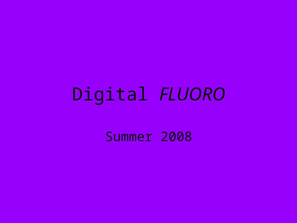
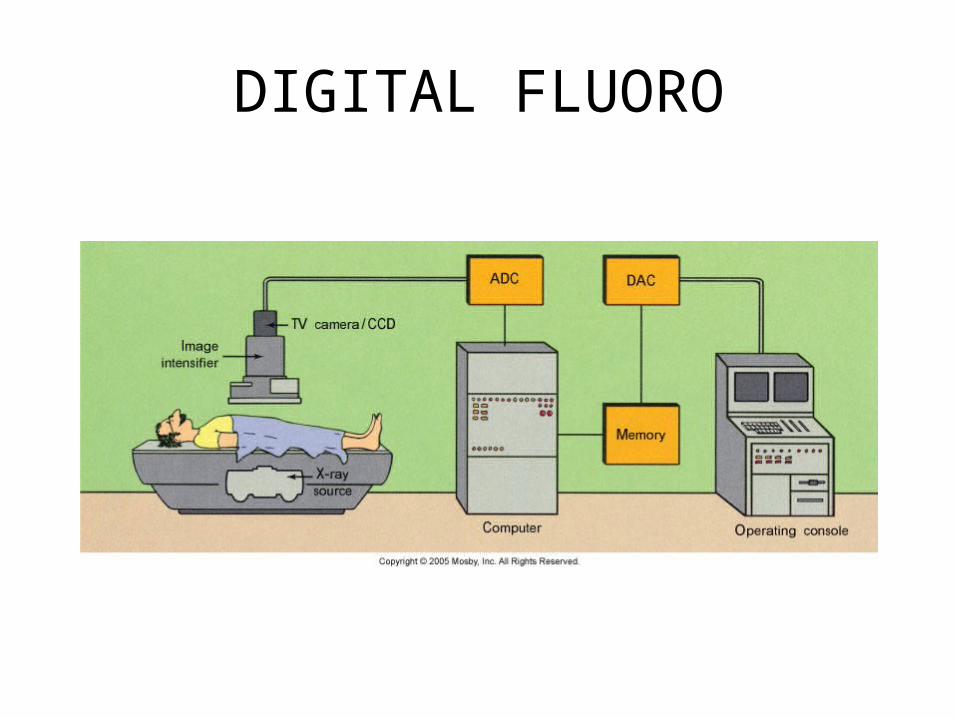
• Digital fluoroscopy is currently most commonly configured as a conventional fluoroscopy system in which the analog video signal is converted to a digital format with an analog-to-digital converter (ADC). An in-depth discussion of digital detector technologies (eg, flat-panel "direct" detection of x rays and charge-coupled device technology) is beyond the scope of this article. After a review of several fundamental digital imaging concepts including binary numbers, pixels, and gray levels, emphasis will be placed on discussions of the digital imaging tools specific to digital fluoroscopy and digital subtraction angiography (DSA).
• Digital fluoroscopy is currently most commonly configured as a conventional fluoroscopy system in which the analog video signal is converted to a digital format with an analog-to-digital converter (ADC).
• With discussions of the digital imaging tools specific to digital fluoroscopy and digital subtraction angiography (DSA).
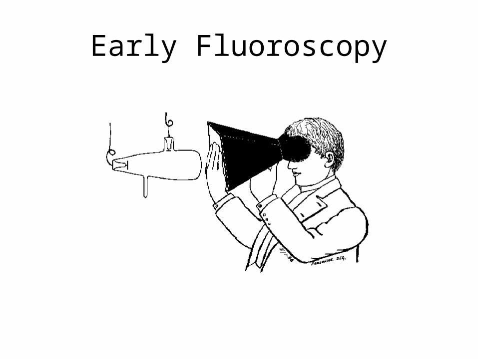
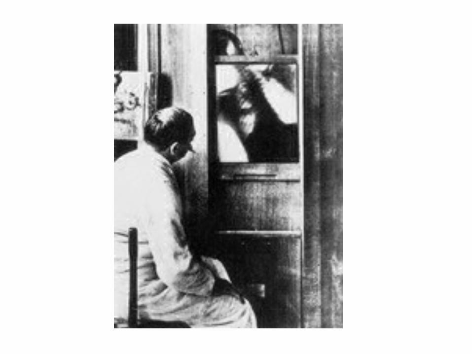
Early Fluoroscopy
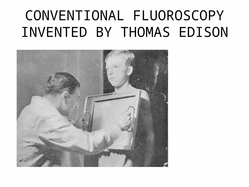
CONVENTIONAL FLUOROSCOPYINVENTED BY THOMAS EDISON
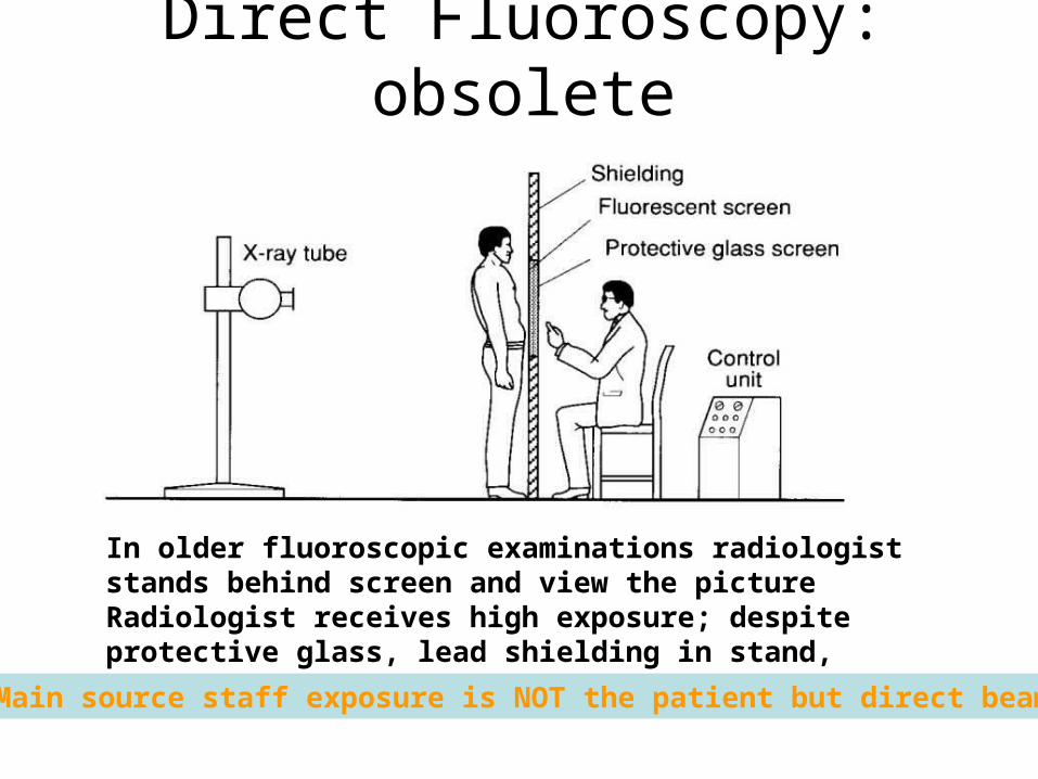
Direct Fluoroscopy: obsolete
In older fluoroscopic examinations radiologist stands behind screen and view the pictureRadiologist receives high exposure; despite protective glass, lead shielding in stand, apron and perhaps goggles
Main source staff exposure is NOT the patient but direct beam
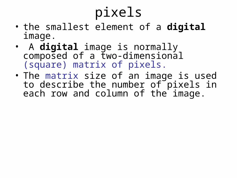
pixels• the smallest element of a digital image.• A digital image is normally composed of a two-
dimensional (square) matrix of pixels.• The matrix size of an image is used to describe
the number of pixels in each row and column of the image.
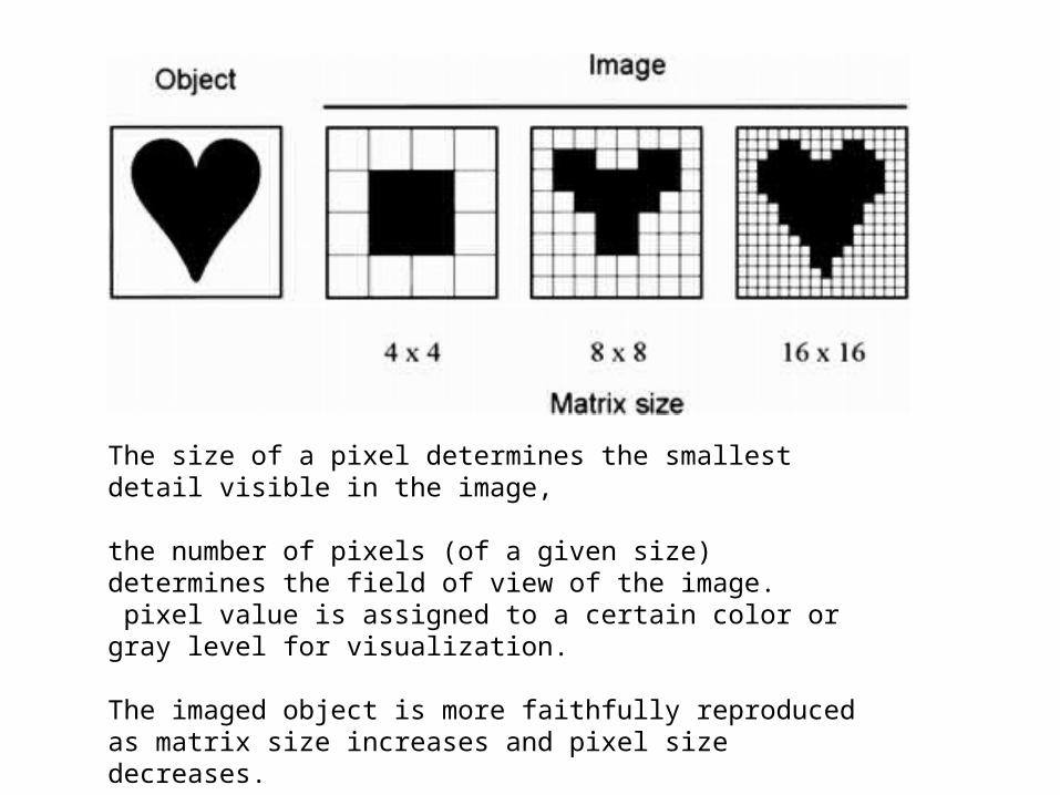
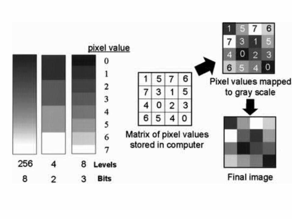
The size of a pixel determines the smallest detail visible in the image,
the number of pixels (of a given size) determines the field of view of the image. pixel value is assigned to a certain color or gray level for visualization. The imaged object is more faithfully reproduced as matrix size increases and pixel size decreases.
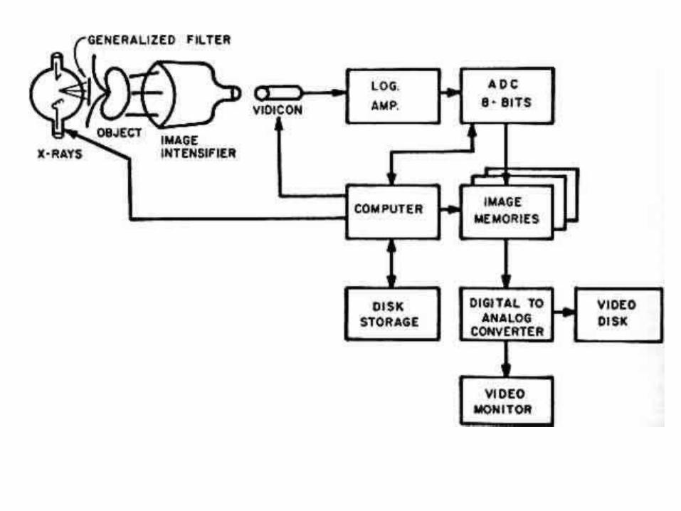
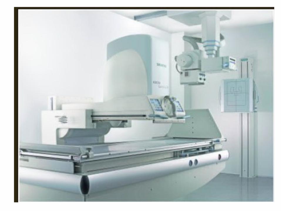
Digital fluoroscopy• is most commonly configured as a conventional
fluoroscopy system (tube, table, image intensifier, video system) in which the analog video signal has been digitized with an ADC.
• Alternatively, digitization may be accomplished with a digital video camera (eg, a charge-coupled device) or via direct capture of x rays with a flat-panel detector.
• For digital fluoroscopy systems in which the analog video signal is digitized with an ADC, the resolution is limited by the resolution of the video camera, which is typically 1–2 line pairs per millimeter.
Digital Image recording
• In newer fluoroscopic systems film recording replaced with digital image recording.
• Digital photospots acquired by recording a digitized video signal and storing it in computer memory.
• Operation fast, convenient.• Image quality can be enhanced by application
of various image processing techniques, including window-level, frame averaging, and edge enhancement.
• But, the spatial resolution of digital photospots is less than that of film images.
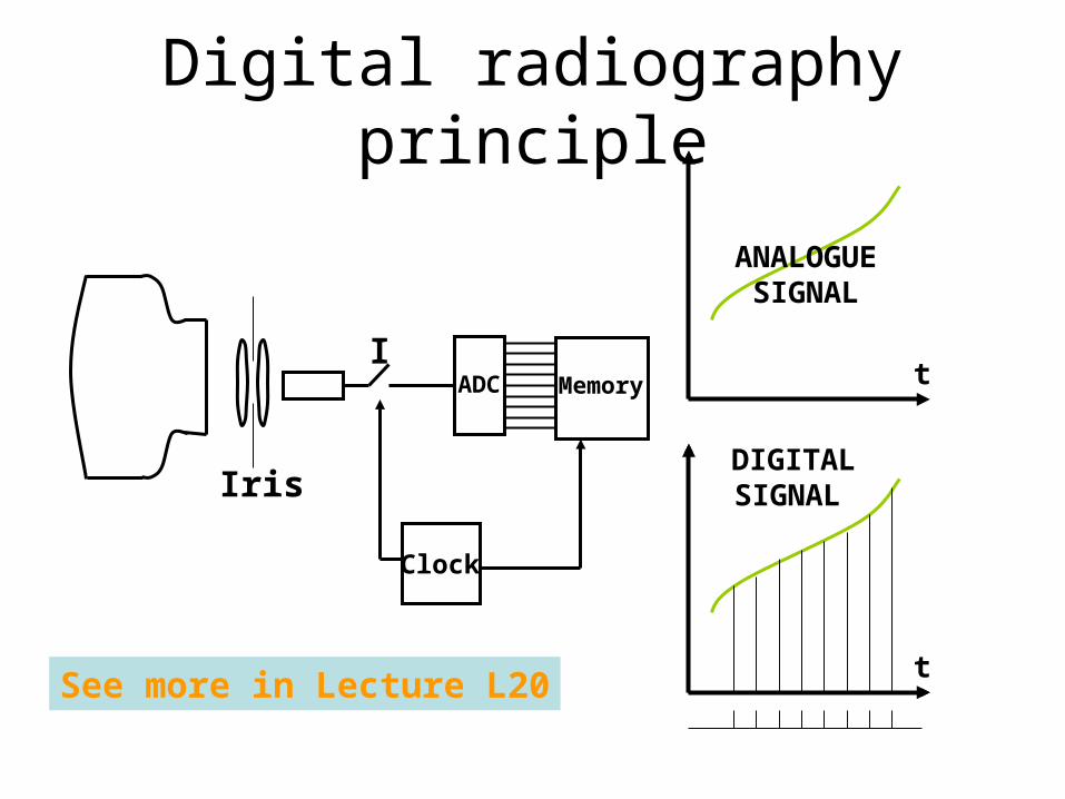
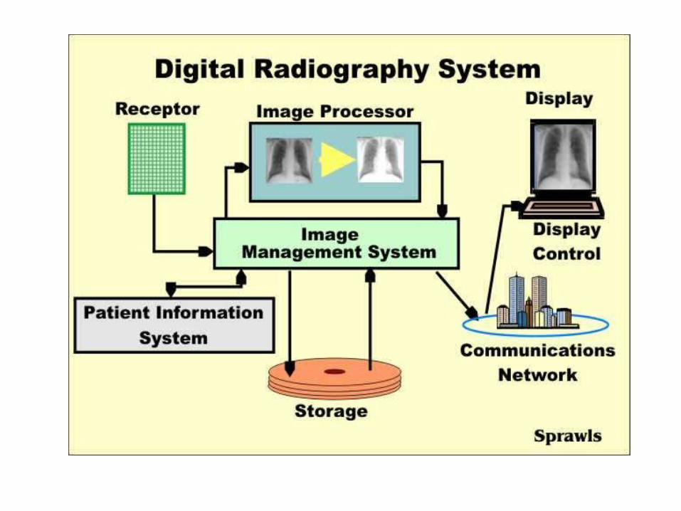
Digital radiography principle
Clock
MemoryADCI
Iris
t
t
ANALOGUESIGNAL
DIGITALSIGNAL
See more in Lecture L20
Digital spot film images
• and photospot images may be acquired by using the same digital fluoroscopy system.
• Individual frames from a digital fluoroscopy sequence can be stored digitally and can be used instead of conventional spot film and photospot images.
• Digital photospot images will have the same characteristics (eg, resolution) as digital fluoroscopic images.
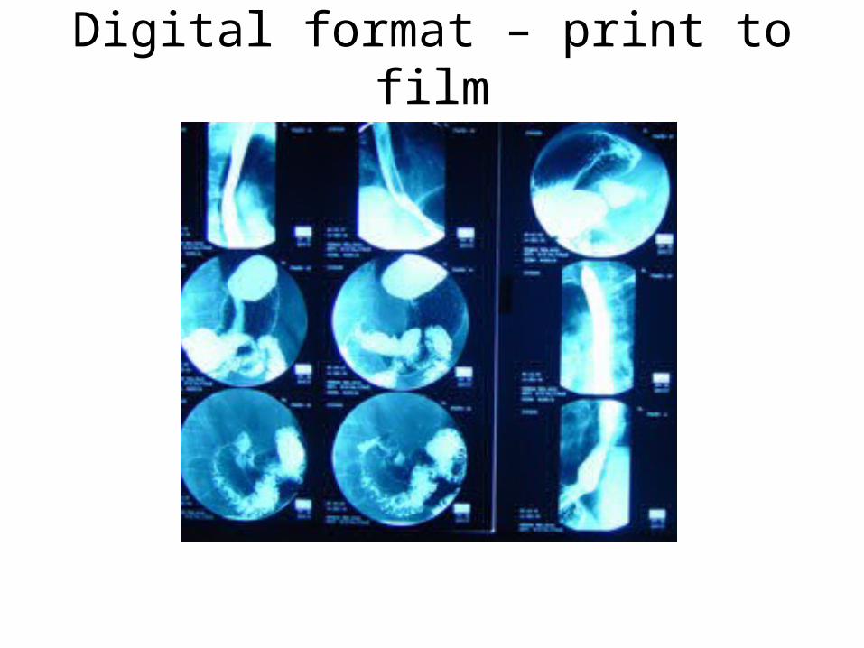
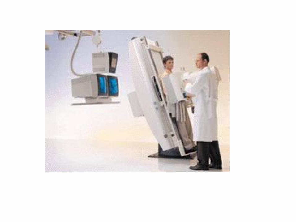
Digital format – print to film
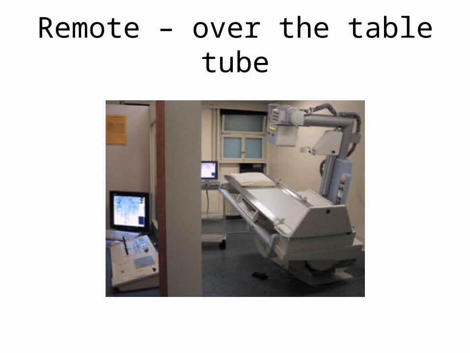
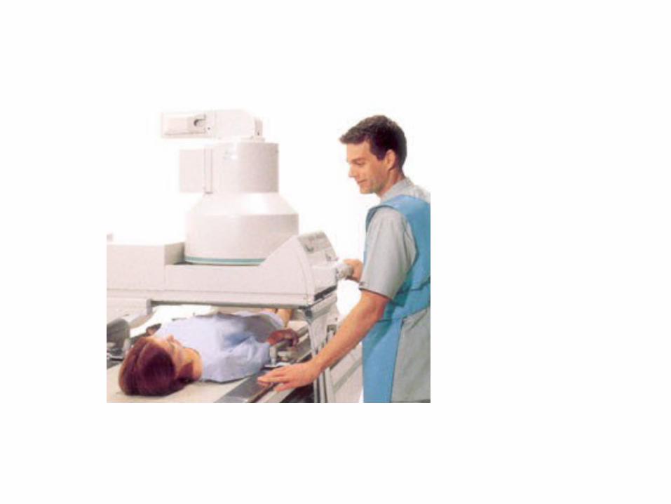
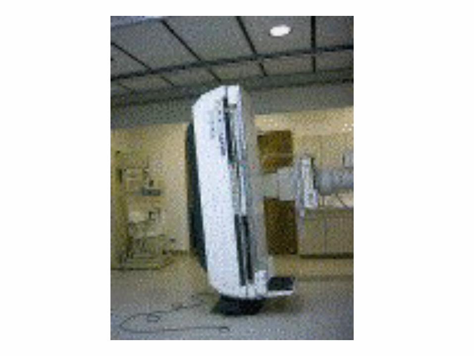
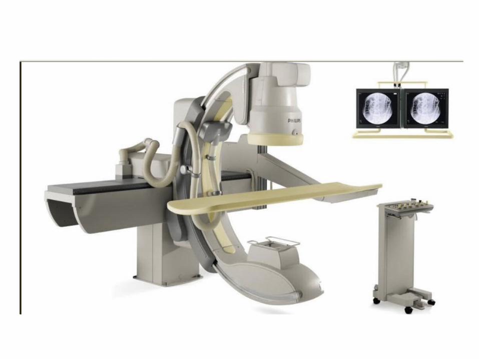
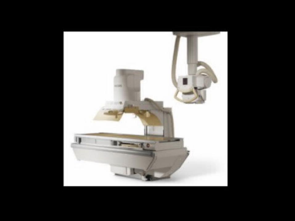
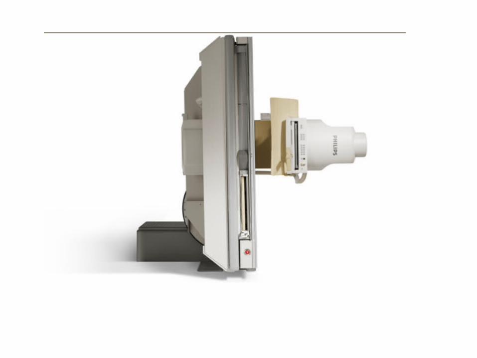
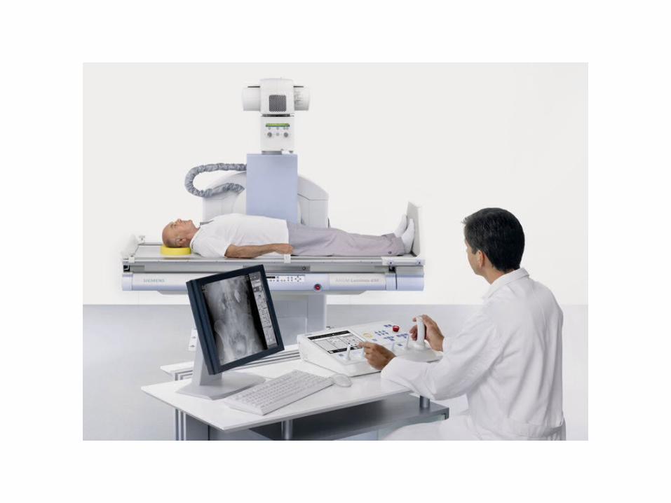
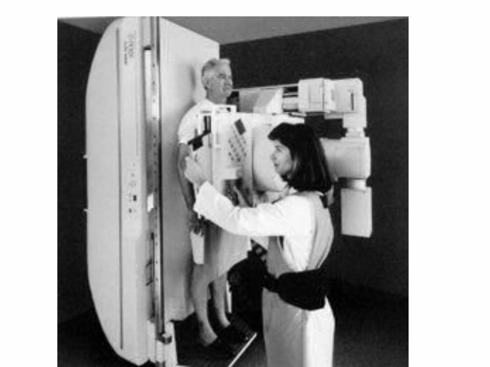
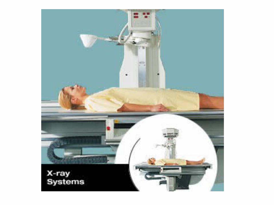
Remote – over the table tube
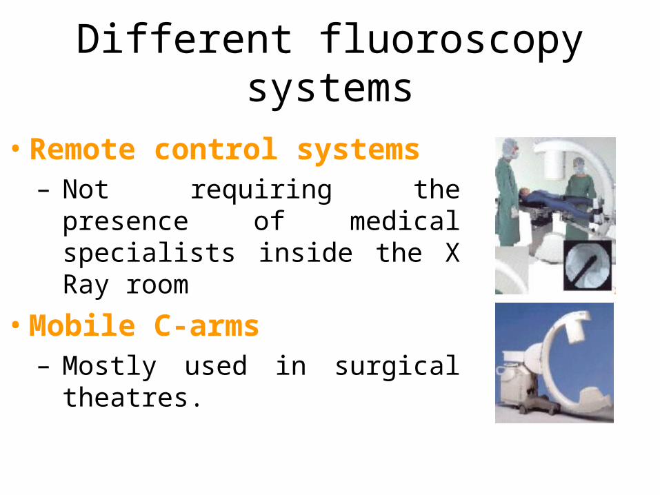
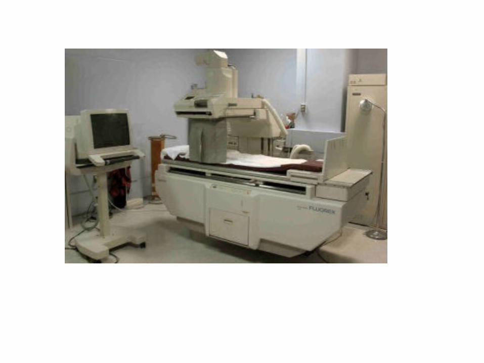
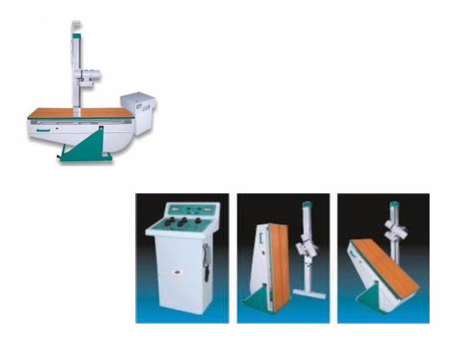
Different fluoroscopy systems
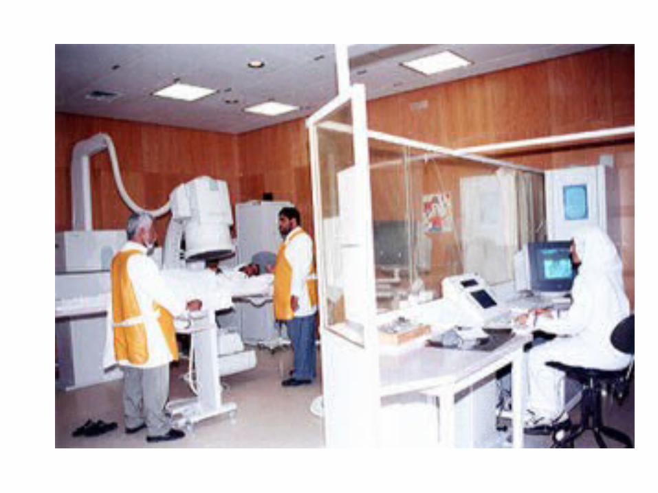
• Remote control systems– Not requiring the presence of
medical specialists inside the X Ray room
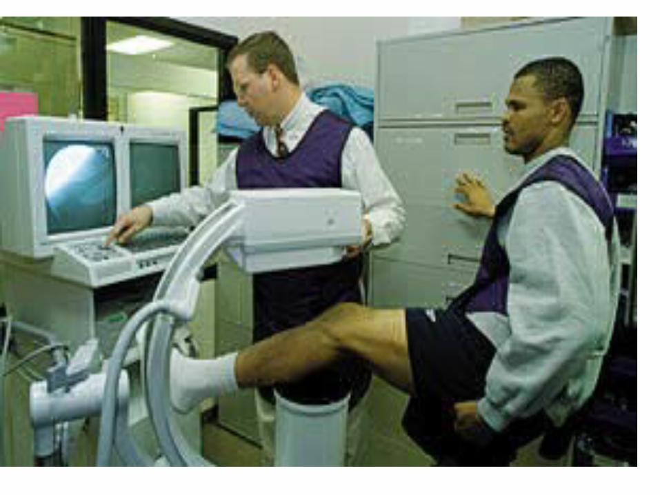
• Mobile C-arms– Mostly used in surgical
theatres.
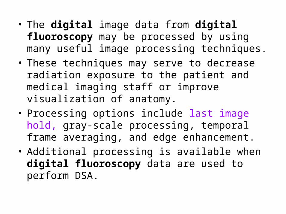
• The digital image data from digital fluoroscopy may be processed by using many useful image processing techniques.
• These techniques may serve to decrease radiation exposure to the patient and medical imaging staff or improve visualization of anatomy.
• Processing options include last image hold, gray-scale processing, temporal frame averaging, and edge enhancement.
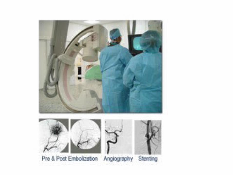
• Additional processing is available when digital fluoroscopy data are used to perform DSA.

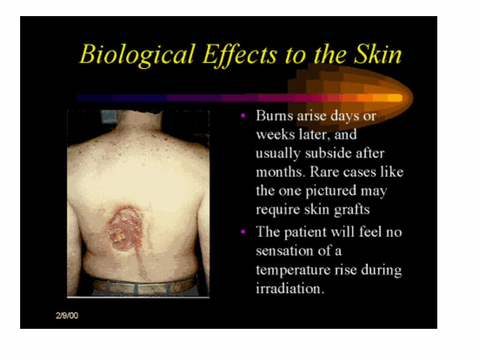
RADIATION PROTECTION
STAT CH 7 & 8
DHS-RHB
RAD PROT/FLUORO SYLLABUS
Radiation Safety and Fluoroscopy
Time Distance Shielding
Also see Intro to Fluoro LectureFrom RT 124 Spring 2007
Patient Protection
• Tabletop exposure rate– Maximum 10 R/min– Typically 1 – 3 R/min
Patient Protection
• Minimum source-to-skin distance– 12” for mobile equipment– 15” for stationary systems
• Audible alarm at 5 mins.
• Same rules for collimation
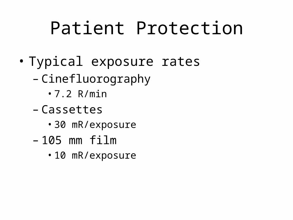
Patient Protection
• Typical exposure rates– Cinefluorography
• 7.2 R/min
– Cassettes• 30 mR/exposure
– 105 mm film• 10 mR/exposure
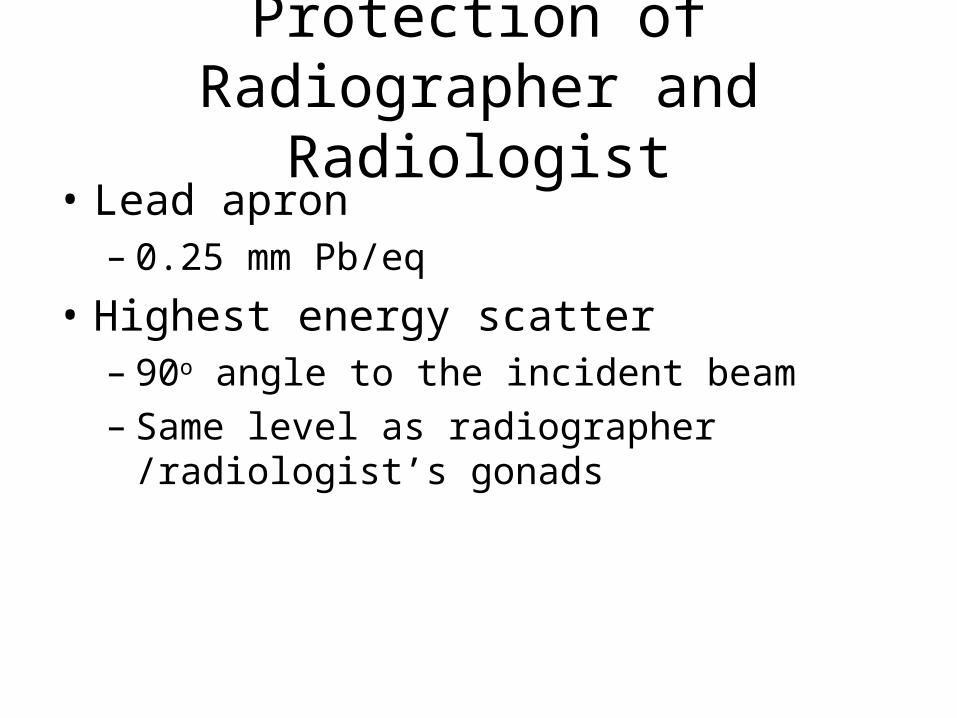
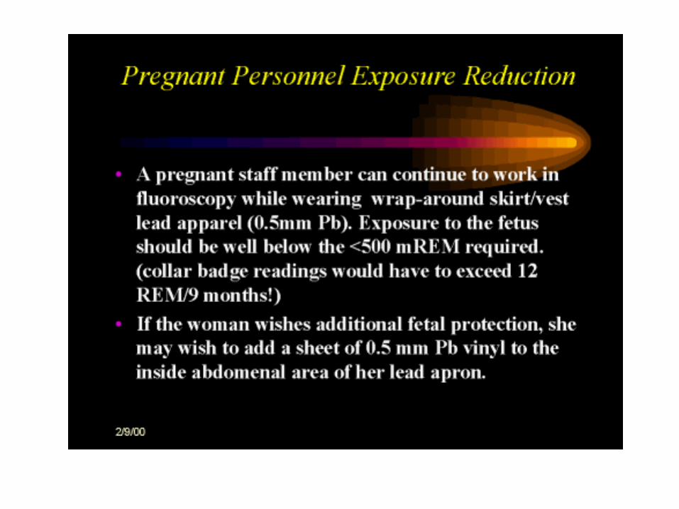
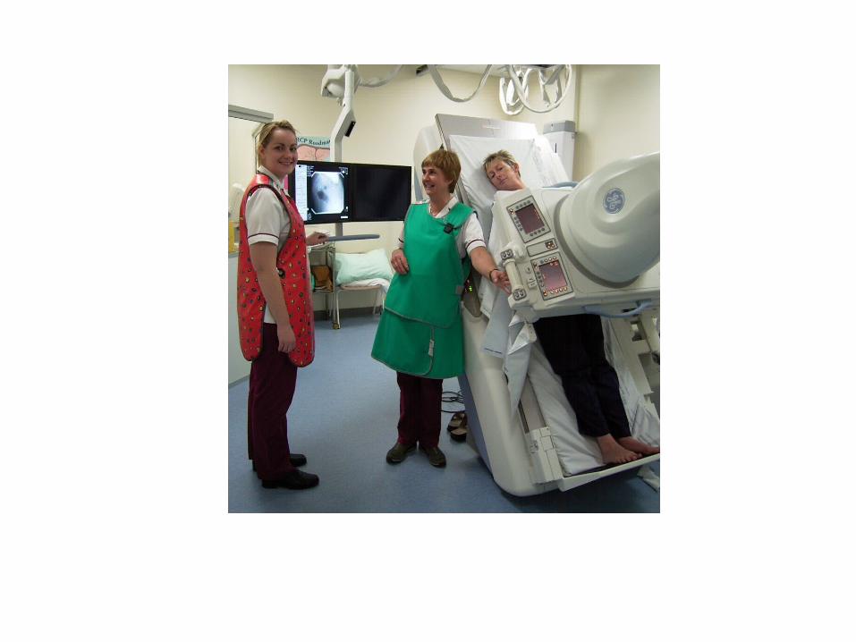
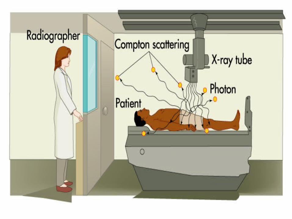
Protection of Radiographer and Radiologist
• Lead apron– 0.25 mm Pb/eq
• Highest energy scatter– 90o angle to the incident beam– Same level as radiographer /radiologist’s
gonads
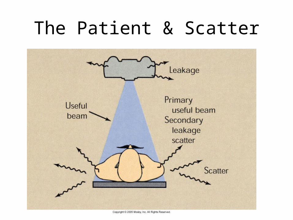
The Patient & Scatter
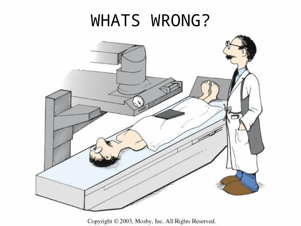
WHATS WRONG?
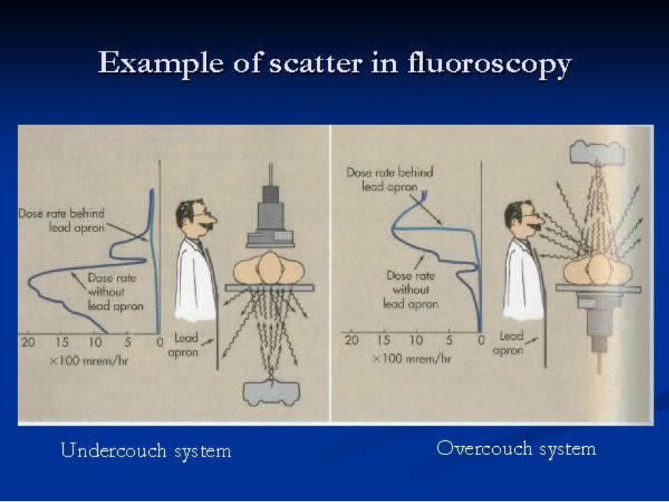

Remote – over the table tube
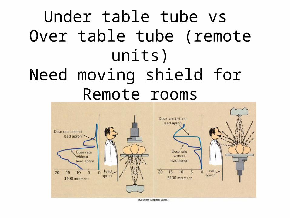
Under table tube vs Over table tube (remote units)
Need moving shield for Remote rooms
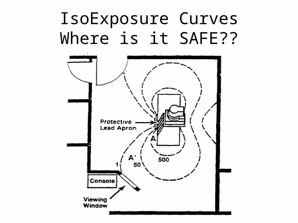
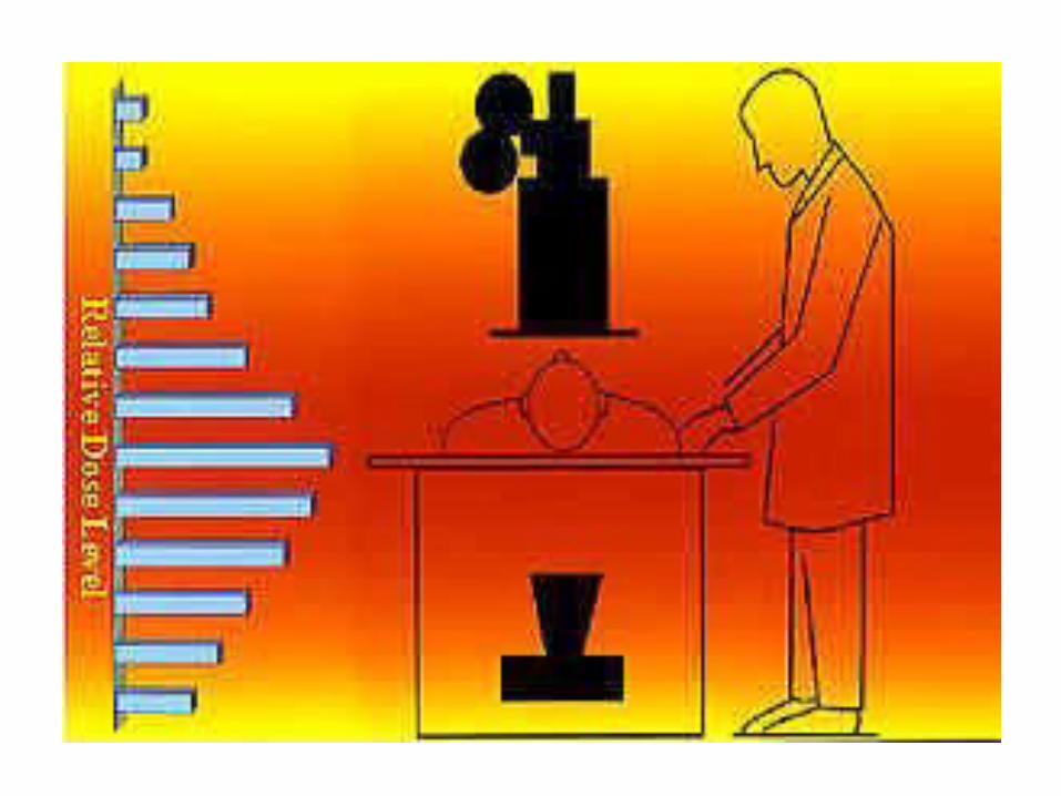
IsoExposure CurvesWhere is it SAFE??
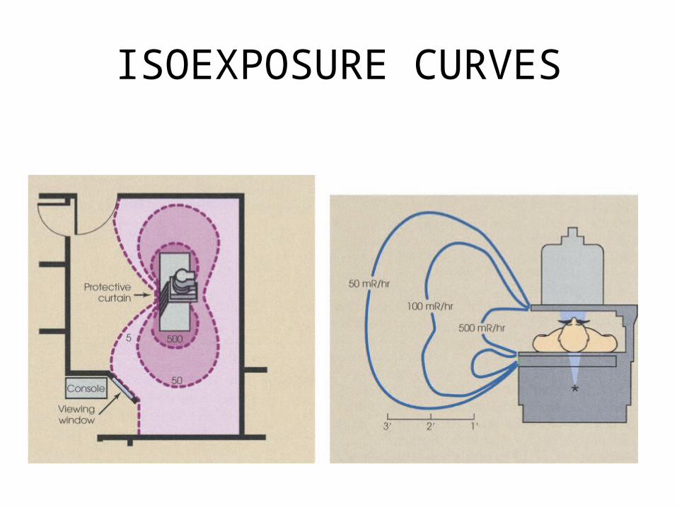
ISOEXPOSURE CURVES
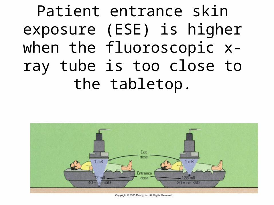
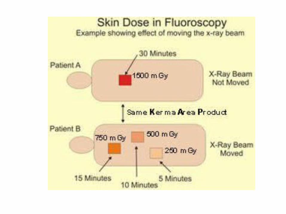
Patient entrance skin exposure (ESE) is higher when the
fluoroscopic x-ray tube is too close to the tabletop.
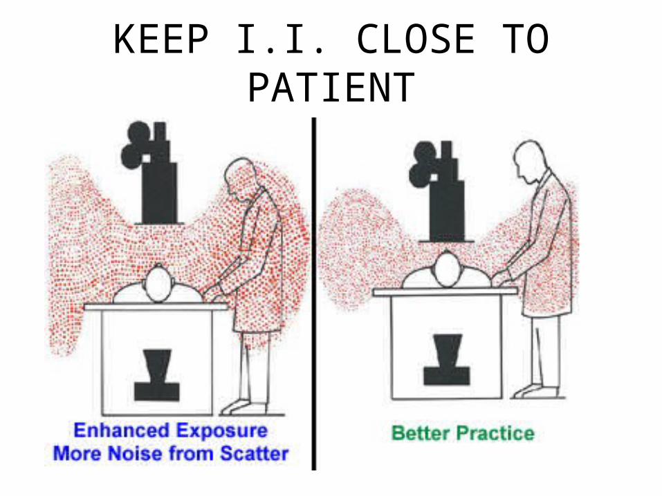
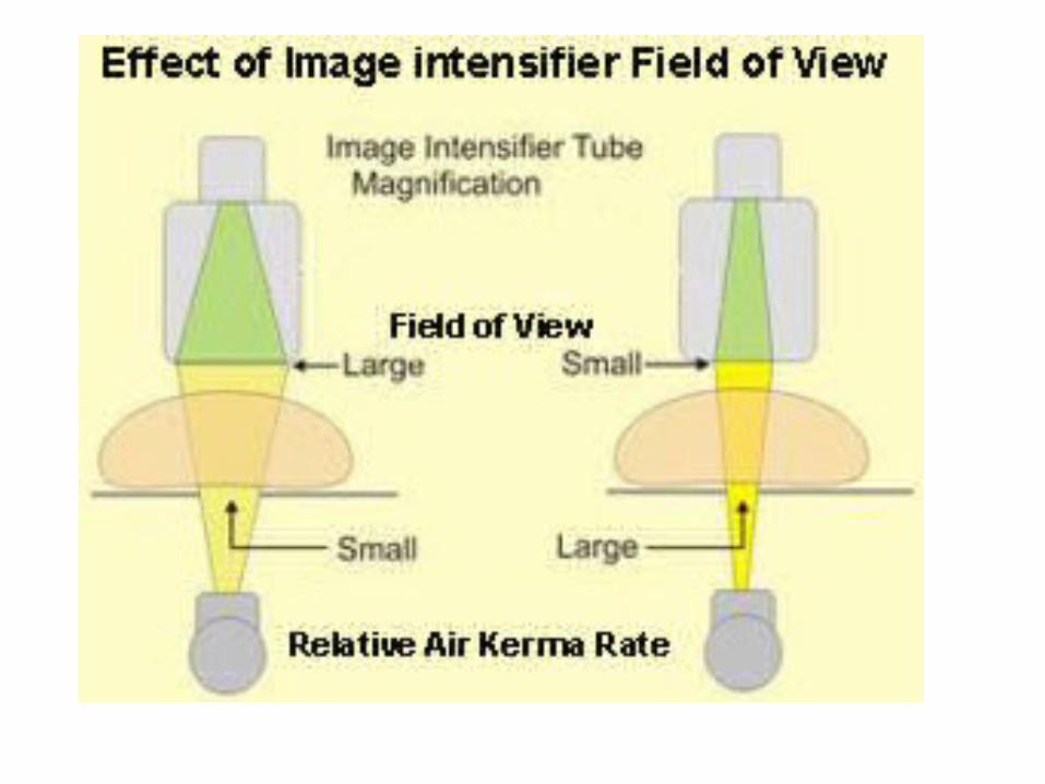
KEEP I.I. CLOSE TO PATIENT
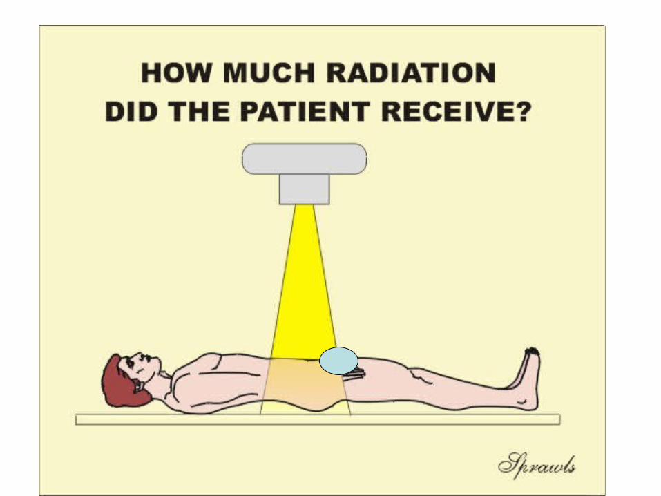
PATIENT EXPOSURE
• REDUCE DISTANCE OF IMAGE INTESIFIER
• INCREASE DISTANCE FROM THE TUBE
PATIENT EXPOSURE
• REDUCE SIZE OF
COLLIMATED BEAM
WHEN POSSIBLE
ESE FOR FLUORO
• TLD PLACED AT SKIN ENTRACE POINT
• 1 – 5 R/MINUTE AVE IS 4 R/MIN
• INTERGRAL DOSE –• 100 ERGS OF TISSUE = 1 RAD EXPOSURE• OR 1 GM RAD = 100 ERGS
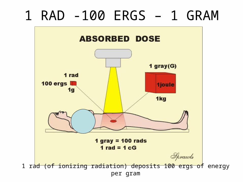
1 RAD -100 ERGS – 1 GRAM
1 rad (of ionizing radiation) deposits 100 ergs of energy per gram
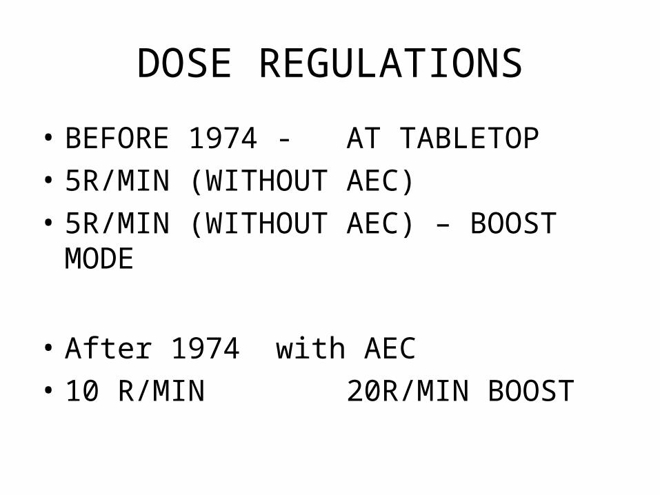
DOSE REGULATIONS
• BEFORE 1974 - AT TABLETOP
• 5R/MIN (WITHOUT AEC)
• 5R/MIN (WITHOUT AEC) – BOOST MODE
• After 1974 with AEC
• 10 R/MIN 20R/MIN BOOST
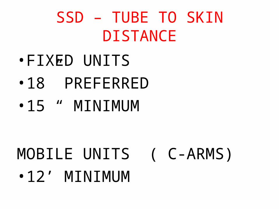
SSD – TUBE TO SKIN DISTANCE
• FIXED UNITS
• 18” PREFERRED
• 15 “ MINIMUM
MOBILE UNITS ( C-ARMS)
• 12’ MINIMUM
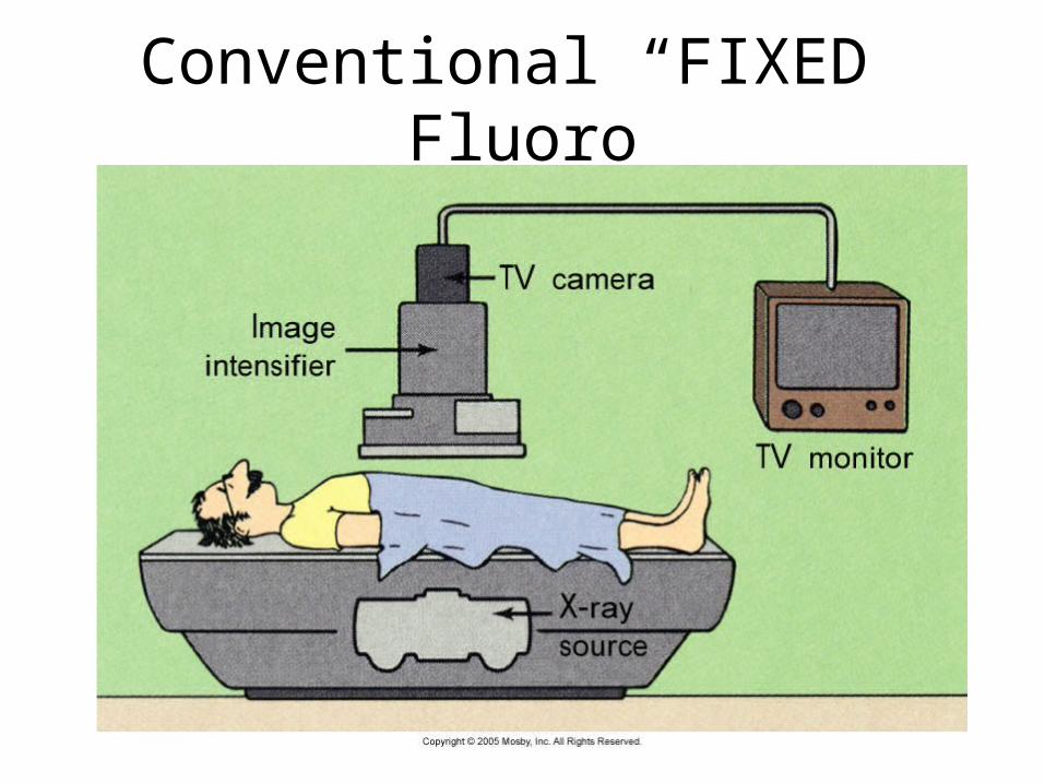
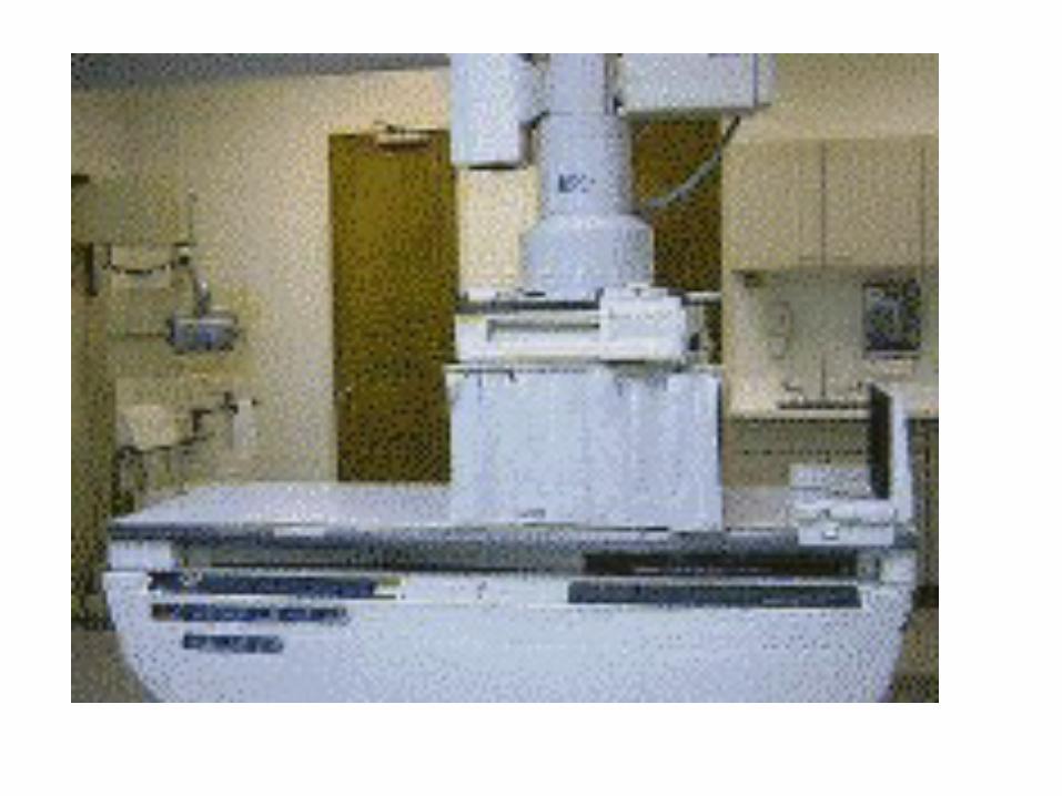
Conventional “FIXED” Fluoro
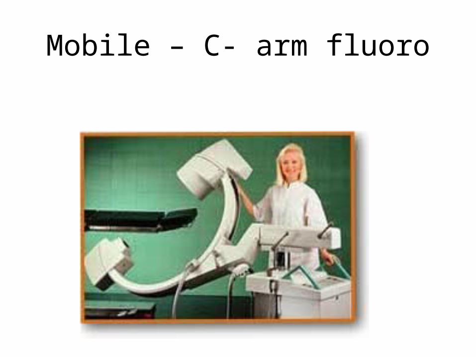
Mobile – C- arm fluoro


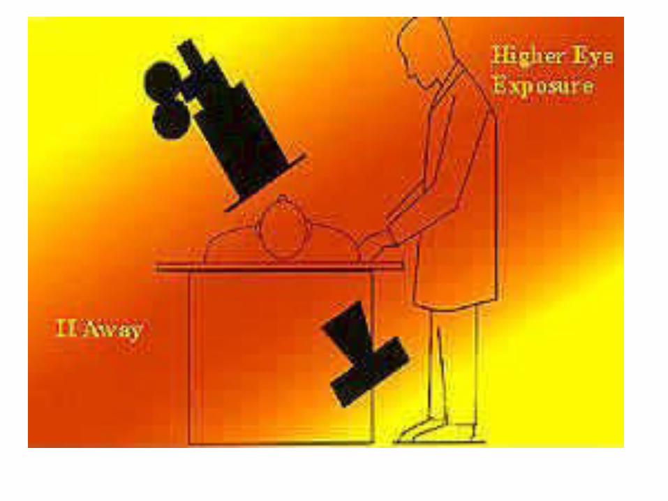
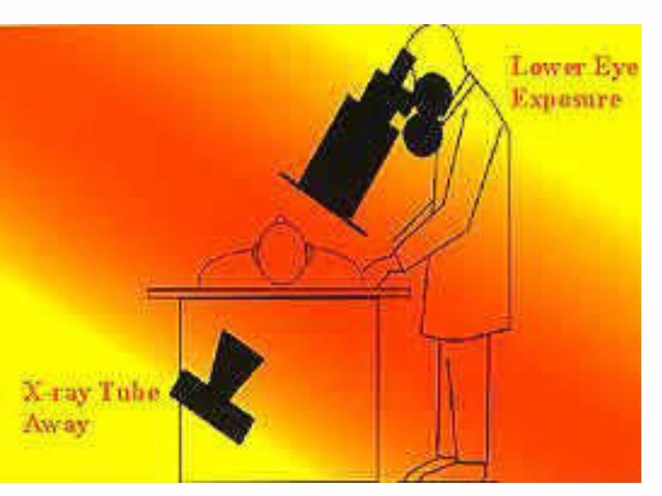
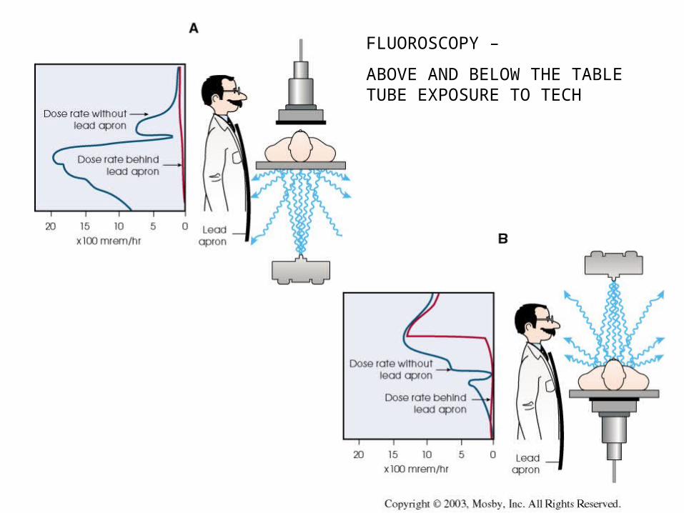
FLUOROSCOPY –
ABOVE AND BELOW THE TABLE TUBE EXPOSURE TO TECH

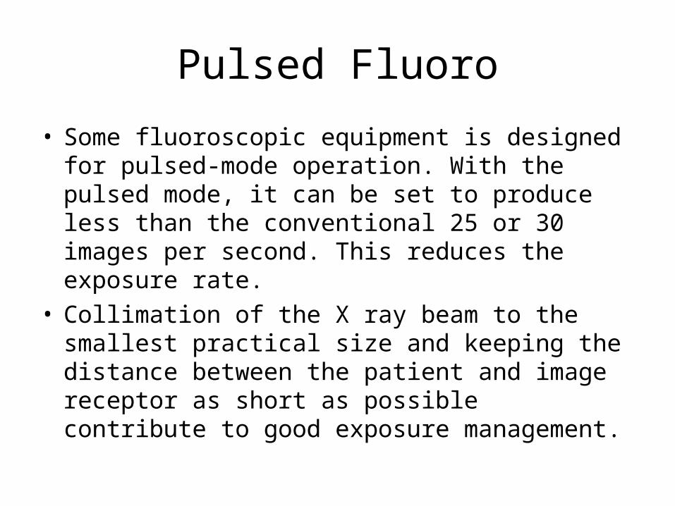
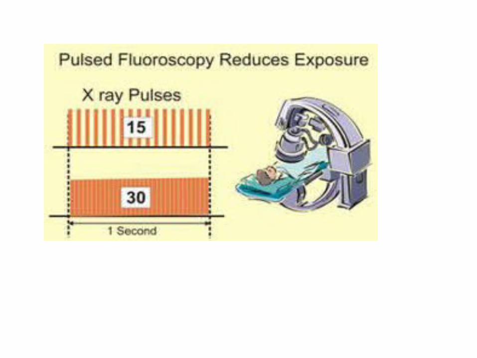
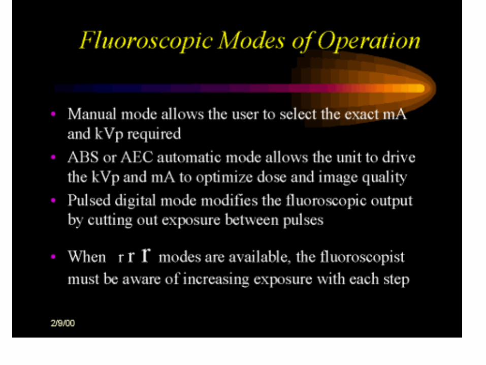
Pulsed Fluoro
• Some fluoroscopic equipment is designed for pulsed-mode operation. With the pulsed mode, it can be set to produce less than the conventional 25 or 30 images per second. This reduces the exposure rate.
• Collimation of the X ray beam to the smallest practical size and keeping the distance between the patient and image receptor as short as possible contribute to good exposure management.
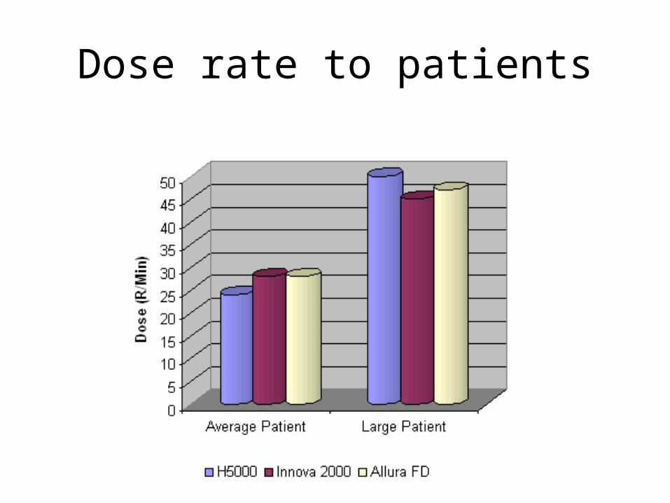
Dose rate to patients
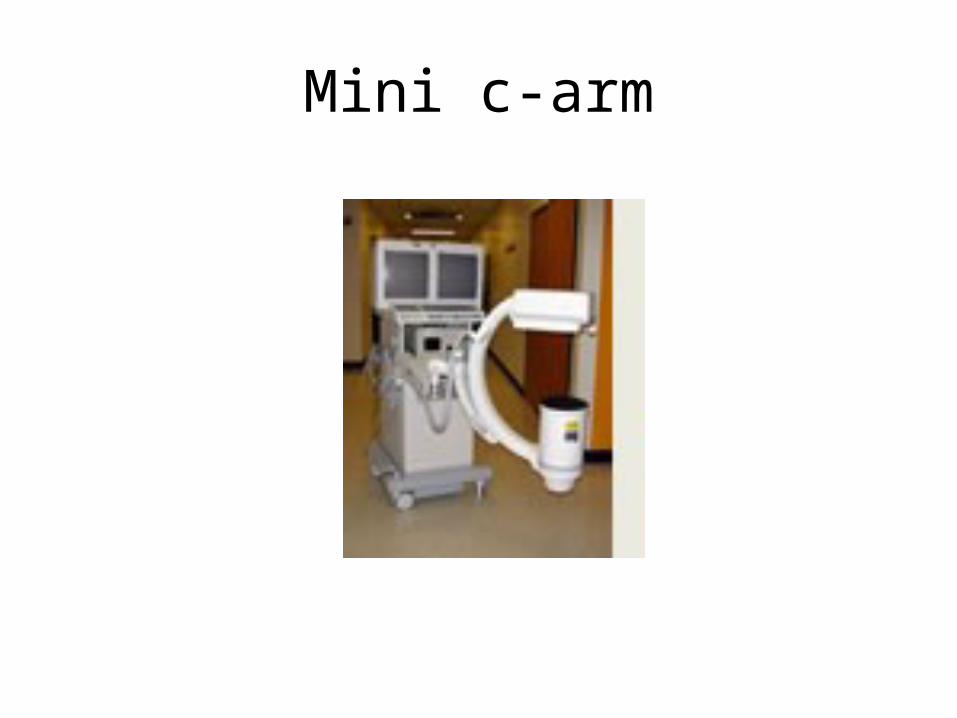
Mini c-arm