Embed Size (px)
Citation preview
Fluoroscopy
Principles of MedicalImaging
Prof. Dr. Philippe Cattin
MIAC, University of Basel
Sep 19th, 2016
Sep 19th, 2016Principles of Medical Imaging
1 of 34 26.09.2016 08:34
Contents
2
4
5
6
8
9
10
11
12
13
15
16
17
18
20
21
22
23
24
26
28
Prof. Dr. Philippe Cattin: Fluoroscopy
Contents
Abstract
1 Introduction
Fluoroscope
Sample Applications
Sample Applications (2)
2 History
Early Fluoroscopes
Early Fluoroscopes (2)
Dark Rooms and Red Goggles
Dark Rooms and Red Goggles (2)
Fluoroscopy Sample Movies
The Shoe-Fitting Fluoroscope
3 Image Intensifier
Image Intensifiers
Image Intensifiers (2)
Input Window
Output Window
4 State-of-the-art Fluoroscopes
Fluoroscopic Imaging Chain
State-of-the-art Fluoroscope Setup
Fluoroscope with Brightness Control
C-Arm
Iso-C 3D
5 Flatpanel Digital Fluoroscopy
Flat Panel Digital Fluoroscopy
6 Modes of Operation
Continuous FluoroscopySep 19th, 2016Principles of Medical Imaging
2 of 34 26.09.2016 08:34
29
30
31
32
33
34
35
37
Pulsed Fluoroscopy
Frame Averaging
Digital Subtraction Arteriography
Last-frame Hold
Road Mapping
Road Mapping Example
Application of the Fluoroscope on TEVAR
7 Fluoroscopy Conclusion
Fluoroscopy Conclusion
Sep 19th, 2016Principles of Medical Imaging
3 of 34 26.09.2016 08:34
Sep 19th, 2016Principles of Medical Imaging
(2)
Prof. Dr. Philippe Cattin: Fluoroscopy
Abstract
4 of 34 26.09.2016 08:34
Introduction
Sep 19th, 2016Principles of Medical Imaging
(4)Fluoroscope
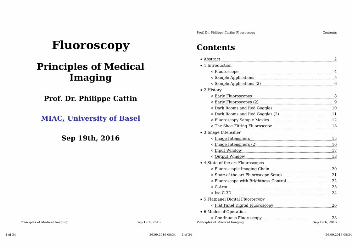
→ Fluoroscopy [http://en.wikipedia.org
/wiki/Fluoroscopy] is an imaging techniquecommonly used by physicians to obtainreal-time images of the internal structuresof a patient through the use of afluoroscope. It is used to visualise:
organ motion
ingested or injected contrast agent
catheterised interventions (inserting
stents, RF ablation,...)
Fig 2.1: A modern Fluoroscope
The first commercial → fluoroscope [http://en.wikipedia.org
/wiki/Fluoroscopy] was developed by → Thomas Alva Edison[http://en.wikipedia.org/wiki/Thomas_Edison] in 1896.
5 of 34 26.09.2016 08:34
Sep 19th, 2016Principles of Medical Imaging
Introduction
(5)
Prof. Dr. Philippe Cattin: Fluoroscopy
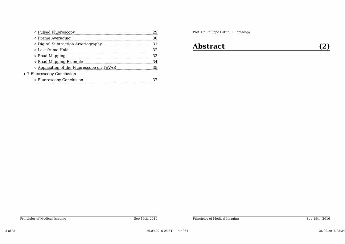
Sample Applications
Fig 2.2: Hand X-ray
Fig 2.3: Fluoroscopy of an RF ablation site
6 of 34 26.09.2016 08:34
Sep 19th, 2016Principles of Medical Imaging
Introduction
(6)
Prof. Dr. Philippe Cattin: Fluoroscopy
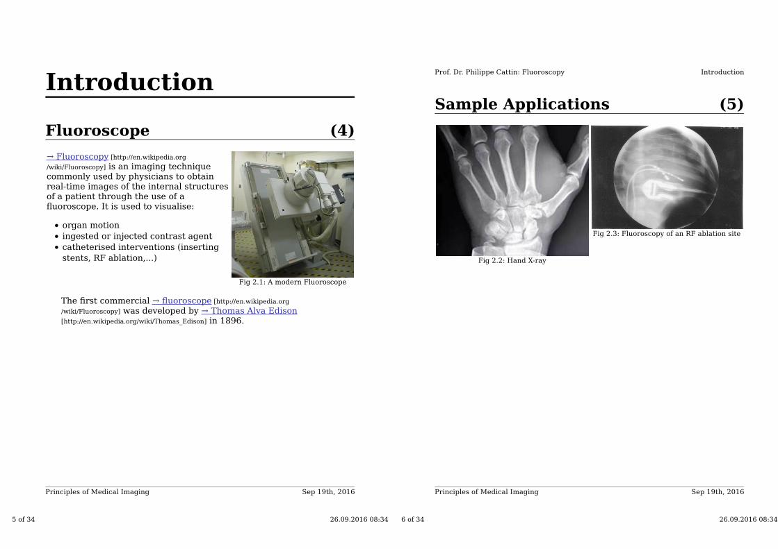
Sample Applications (2)
Sample applications with CT Fluoroscopy e.g. an IsoC3D Fluoroscope
Fig 2.4: A radiologist's hand accidentally
slips into the primary beam during a
fluoroscopy procedureFig 2.5: Cervical spine biopsy with CT
Fluoroscopy
7 of 34 26.09.2016 08:34
History
Sep 19th, 2016Principles of Medical Imaging
(8)Early Fluoroscopes
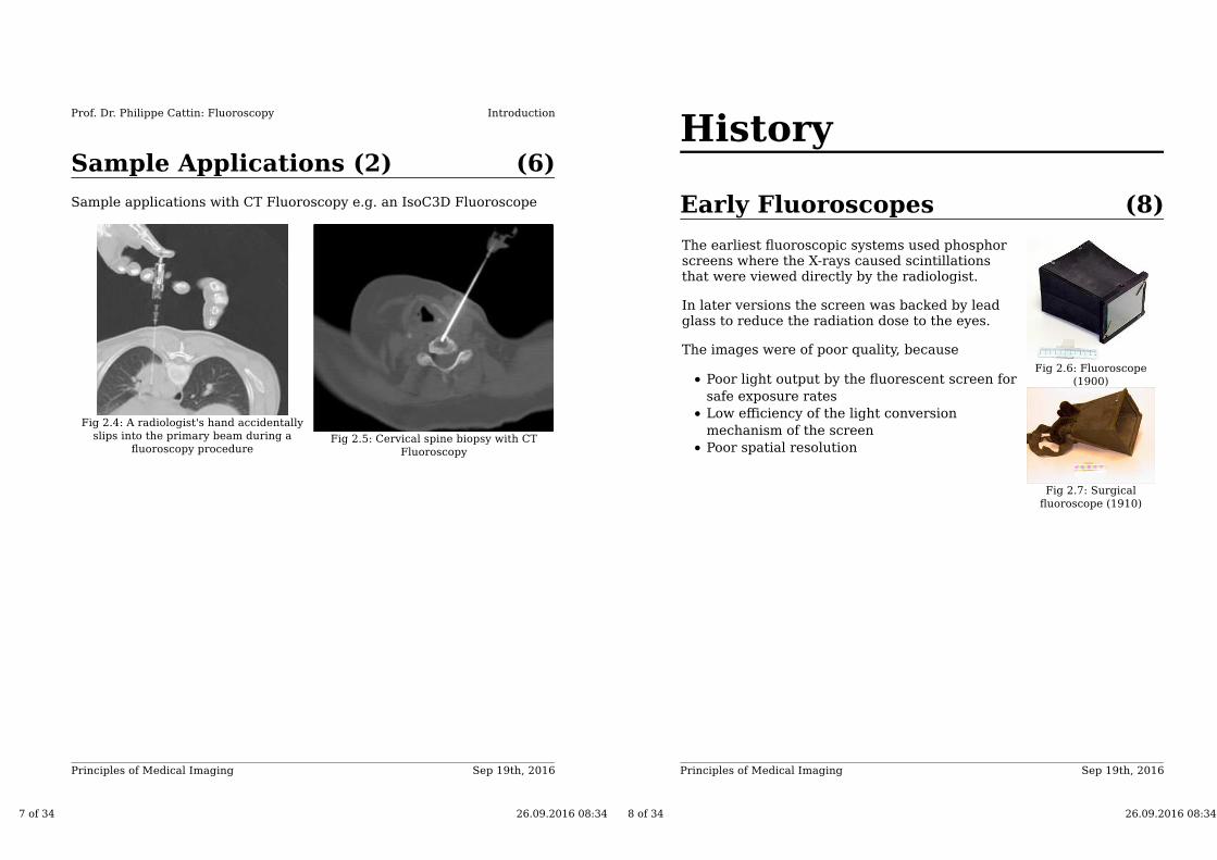
The earliest fluoroscopic systems used phosphorscreens where the X-rays caused scintillationsthat were viewed directly by the radiologist.
In later versions the screen was backed by leadglass to reduce the radiation dose to the eyes.
The images were of poor quality, because
Poor light output by the fluorescent screen for
safe exposure rates
Low efficiency of the light conversion
mechanism of the screen
Poor spatial resolution
Fig 2.6: Fluoroscope
(1900)
Fig 2.7: Surgical
fluoroscope (1910)
8 of 34 26.09.2016 08:34
Sep 19th, 2016Principles of Medical Imaging
History
(9)
Prof. Dr. Philippe Cattin: Fluoroscopy
Early Fluoroscopes (2)
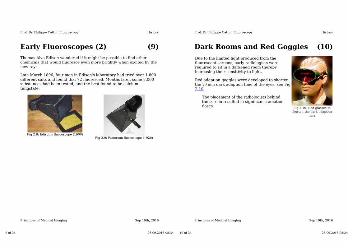
Thomas Alva Edison wondered if it might be possible to find otherchemicals that would fluoresce even more brightly when excited by thenew rays.
Late March 1896, four men in Edison's laboratory had tried over 1,800different salts and found that 72 fluoresced. Months later, some 8,000substances had been tested, and the best found to be calciumtungstate.
Fig 2.8: Edison's fluoroscope (1900)Fig 2.9: Patterson fluoroscope (1920)
9 of 34 26.09.2016 08:34
Sep 19th, 2016Principles of Medical Imaging
History
(10)
Prof. Dr. Philippe Cattin: Fluoroscopy
Dark Rooms and Red Goggles
Due to the limited light produced from thefluorescent screens, early radiologists wererequired to sit in a darkened room therebyincreasing their sensitivity to light.
Red adaption goggles were developed to shortenthe dark adaption time of the eyes, see Fig2.10.
The placement of the radiologists behindthe screen resulted in significant radiationdoses.
Fig 2.10: Red glasses to
shorten the dark adaption
time
10 of 34 26.09.2016 08:34

Sep 19th, 2016Principles of Medical Imaging
History
(11)
Prof. Dr. Philippe Cattin: Fluoroscopy
Dark Rooms and Red Goggles(2)
Fig 2.11: Protective cloths (1910)
Fig 2.12: Modern protective underwear
11 of 34 26.09.2016 08:34
Sep 19th, 2016Principles of Medical Imaging
History
(12)
Prof. Dr. Philippe Cattin: Fluoroscopy
Fluoroscopy Sample Movies
Fig 2.13: Fluoroscopy of the neck Fig 2.14: US Army video (WW2)
12 of 34 26.09.2016 08:34
Sep 19th, 2016Principles of Medical Imaging
History
(13)
Prof. Dr. Philippe Cattin: Fluoroscopy
The Shoe-Fitting Fluoroscope
The → shoe-fitting fluoroscope [http://en.wikipedia.org
/wiki/Shoe-Fitting_Fluoroscope] (Pedoscope) is thought tohave been invented around 1924 by ClarenceKarrer while he worked with his father, sellingsurgical supplies and X-ray equipment. Afterbuilding and selling several, he was asked by theRadiological Society of North America and someradiologists to stop because it lowered the dignityof the profession of radiology. Karrer complied,but one of his father's employees quit thecompany and patented this device.For radioprotection reasons they stoppedproducing this system in the late 50's.
The level of exposure ranged from. The current maximum
allowed exposure to workers in nuclearpower stations in the USA is
Fig 2.15: Special X-ray
unit for shoe shops in the
1930s through 1950s
13 of 34 26.09.2016 08:34
Image Intensifier
Sep 19th, 2016Principles of Medical Imaging
(15)Image Intensifiers
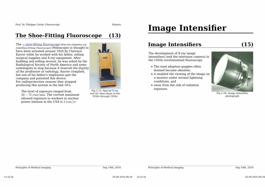
The development of X-ray imageintensifiers (and the television camera) inthe 1950s revolutionised fluoroscopy.
The read adaption goggles often
donned became obsolete,
it enabled the viewing of the image on
a monitor under normal lightning
conditions, and
away from the risk of radiation
exposure.
Fig 2.16: Image intensifier
photograph
14 of 34 26.09.2016 08:34
Sep 19th, 2016Principles of Medical Imaging
Image Intensifier
(16)
Prof. Dr. Philippe Cattin: Fluoroscopy
Image Intensifiers (2)
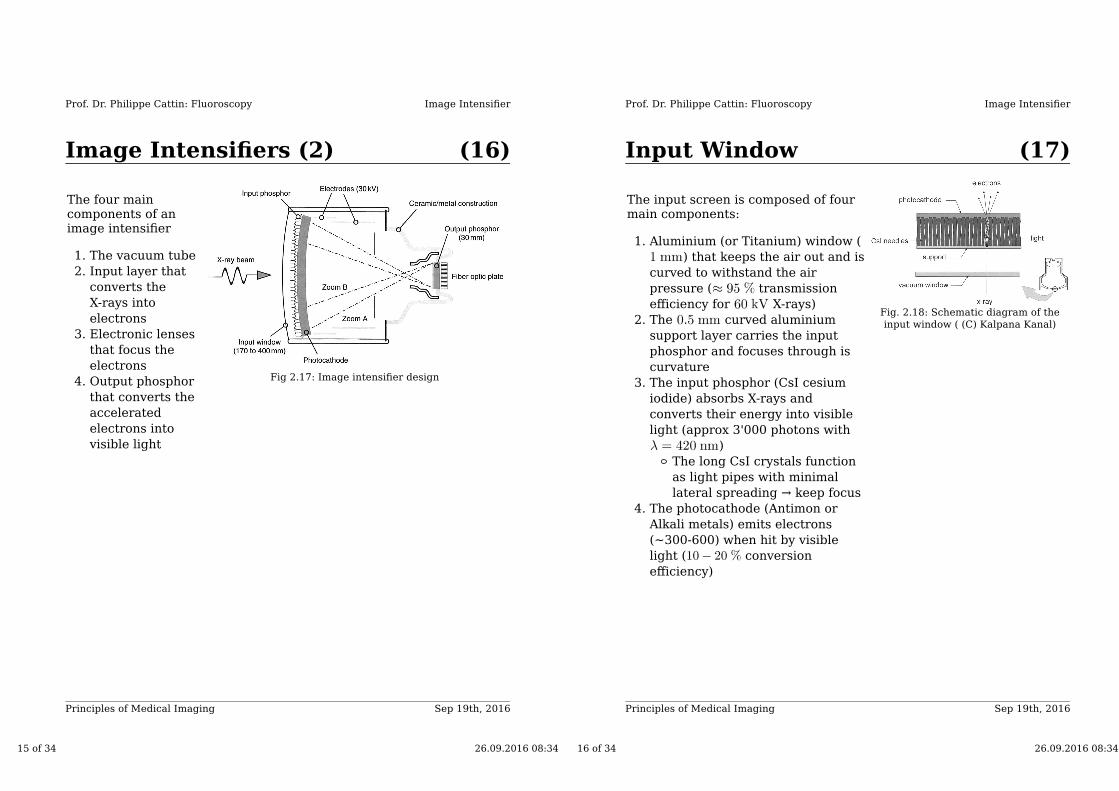
The four maincomponents of animage intensifier
The vacuum tube1.
Input layer that
converts the
X-rays into
electrons
2.
Electronic lenses
that focus the
electrons
3.
Output phosphor
that converts the
accelerated
electrons into
visible light
4. Fig 2.17: Image intensifier design
15 of 34 26.09.2016 08:34
Sep 19th, 2016Principles of Medical Imaging
Image Intensifier
(17)
Prof. Dr. Philippe Cattin: Fluoroscopy
Input Window
The input screen is composed of fourmain components:
Aluminium (or Titanium) window (
) that keeps the air out and is
curved to withstand the air
pressure ( transmission
efficiency for X-rays)
1.
The curved aluminium
support layer carries the input
phosphor and focuses through is
curvature
2.
The input phosphor (CsI cesium
iodide) absorbs X-rays and
converts their energy into visible
light (approx 3'000 photons with
)
The long CsI crystals function
as light pipes with minimal
lateral spreading → keep focus
3.
The photocathode (Antimon or
Alkali metals) emits electrons
(~300-600) when hit by visible
light ( conversion
efficiency)
4.
Fig. 2.18: Schematic diagram of the
input window ( (C) Kalpana Kanal)
16 of 34 26.09.2016 08:34
Sep 19th, 2016Principles of Medical Imaging
Image Intensifier
(18)
Prof. Dr. Philippe Cattin: Fluoroscopy
Output Window
The output window of the imageintensifier is composed of:
The anode is very thin → each
electron causes approx 1000 light
photons
1.
The output phosphor is made of
Zinc cadmium sulfide (ZnCdS)
2.
The reduction in image diameter (
) leads to an intensity
amplification → Minification Gain
3.
Light bouncing around the output
window is called Veiling glare and
reduces image contrast
4.
Fig. 2.19: Schematic diagram of the
output window
17 of 34 26.09.2016 08:34
State-of-the-artFluoroscopes
Sep 19th, 2016Principles of Medical Imaging
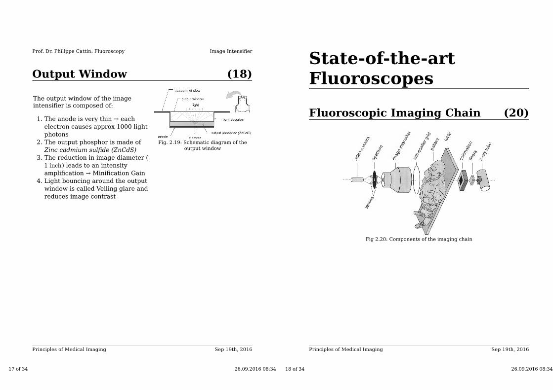
(20)Fluoroscopic Imaging Chain
Fig 2.20: Components of the imaging chain
18 of 34 26.09.2016 08:34
Sep 19th, 2016Principles of Medical Imaging
State-of-the-art Fluoroscopes
(21)
Prof. Dr. Philippe Cattin: Fluoroscopy
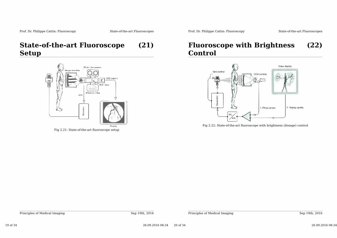
State-of-the-art FluoroscopeSetup
Fig 2.21: State-of-the-art fluoroscope setup
19 of 34 26.09.2016 08:34
Sep 19th, 2016Principles of Medical Imaging
State-of-the-art Fluoroscopes
(22)
Prof. Dr. Philippe Cattin: Fluoroscopy
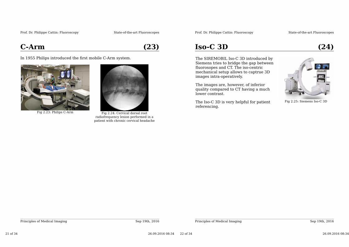
Fluoroscope with BrightnessControl
Fig 2.22: State-of-the-art fluoroscope with brightness (dosage) control
20 of 34 26.09.2016 08:34
Sep 19th, 2016Principles of Medical Imaging
State-of-the-art Fluoroscopes
(23)
Prof. Dr. Philippe Cattin: Fluoroscopy
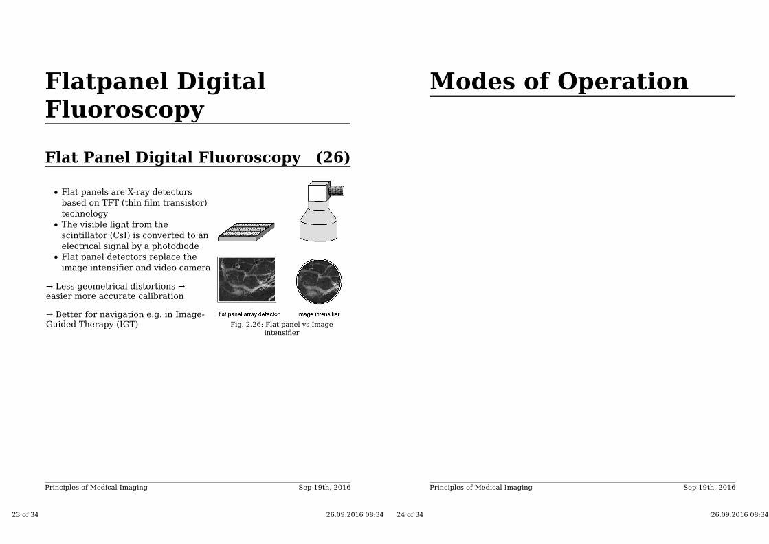
C-Arm
In 1955 Philips introduced the first mobile C-Arm system.
Fig 2.23: Philips C-Arm Fig 2.24: Cervical dorsal root
radiofrequency lesion performed in a
patient with chronic cervical headache
21 of 34 26.09.2016 08:34
Sep 19th, 2016Principles of Medical Imaging
State-of-the-art Fluoroscopes
(24)
Prof. Dr. Philippe Cattin: Fluoroscopy
Iso-C 3D
The SIREMOBIL Iso-C 3D introduced bySiemens tries to bridge the gap betweenfluorosopes and CT. The iso-centricmechanical setup allows to captrue 3Dimages intra-operatively.
The images are, however, of inferiorquality compared to CT having a muchlower contrast.
The Iso-C 3D is very helpful for patientreferencing.
Fig 2.25: Siemens Iso-C 3D
22 of 34 26.09.2016 08:34
Flatpanel DigitalFluoroscopy
Sep 19th, 2016Principles of Medical Imaging
(26)Flat Panel Digital Fluoroscopy
Flat panels are X-ray detectors
based on TFT (thin film transistor)
technology
The visible light from the
scintillator (CsI) is converted to an
electrical signal by a photodiode
Flat panel detectors replace the
image intensifier and video camera
→ Less geometrical distortions →easier more accurate calibration
→ Better for navigation e.g. in Image-Guided Therapy (IGT) Fig. 2.26: Flat panel vs Image
intensifier
23 of 34 26.09.2016 08:34
Modes of Operation
Sep 19th, 2016Principles of Medical Imaging
24 of 34 26.09.2016 08:34
Sep 19th, 2016Principles of Medical Imaging
(28)Continuous Fluoroscopy
X-ray beam continuously on (Tube
current or higher)
Display at → per
frame
Blurring due to patient motion is
acceptable
A special high X-ray dose protocol
exists for obese patients→ audio
warning
Fig 2.27: Angiography with a
conventional Image intensifier
25 of 34 26.09.2016 08:34
Sep 19th, 2016Principles of Medical Imaging
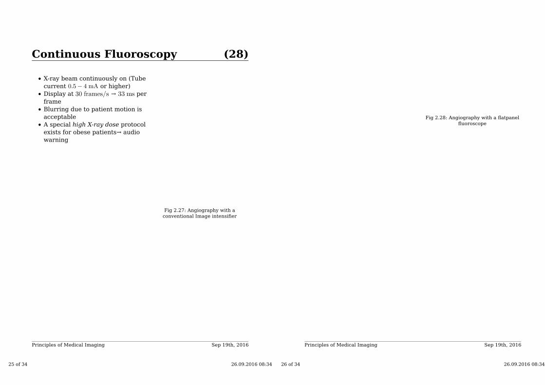
Fig 2.28: Angiography with a flatpanel
fluoroscope
26 of 34 26.09.2016 08:34
Sep 19th, 2016Principles of Medical Imaging
Modes of Operation
(29)
Prof. Dr. Philippe Cattin: Fluoroscopy
Pulsed Fluoroscopy
Pulsed Fluoroscopy is used when the high temporal resolution is notrequired:
Series of short X-ray pulses at e.g. per pulse and a frame rate
of
The shorter exposure time reduces motion artifacts
Other frame rates also available: ,
→ allows to spare X-ray dosage.
27 of 34 26.09.2016 08:34
Sep 19th, 2016Principles of Medical Imaging
Modes of Operation
(30)
Prof. Dr. Philippe Cattin: Fluoroscopy
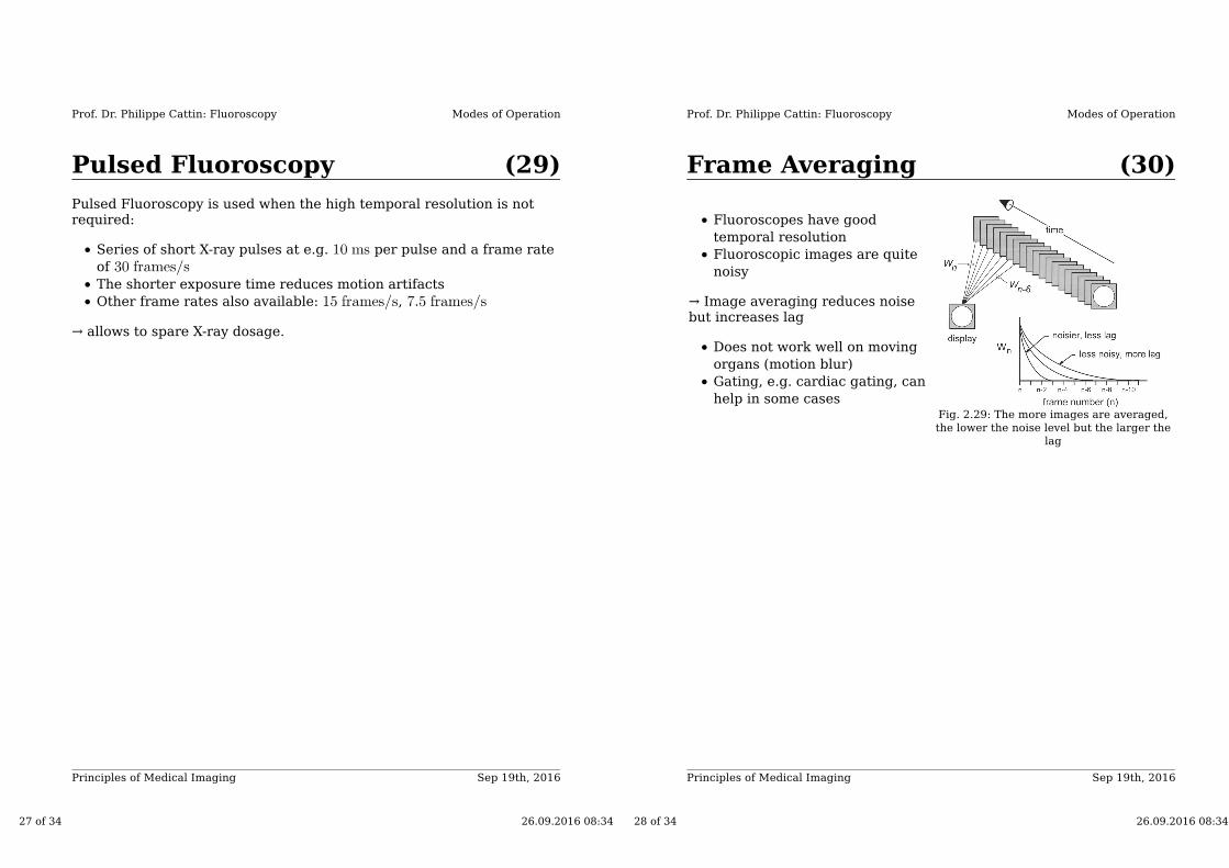
Frame Averaging
Fluoroscopes have good
temporal resolution
Fluoroscopic images are quite
noisy
→ Image averaging reduces noisebut increases lag
Does not work well on moving
organs (motion blur)
Gating, e.g. cardiac gating, can
help in some casesFig. 2.29: The more images are averaged,
the lower the noise level but the larger the
lag
28 of 34 26.09.2016 08:34
Sep 19th, 2016Principles of Medical Imaging
Modes of Operation
(31)
Prof. Dr. Philippe Cattin: Fluoroscopy
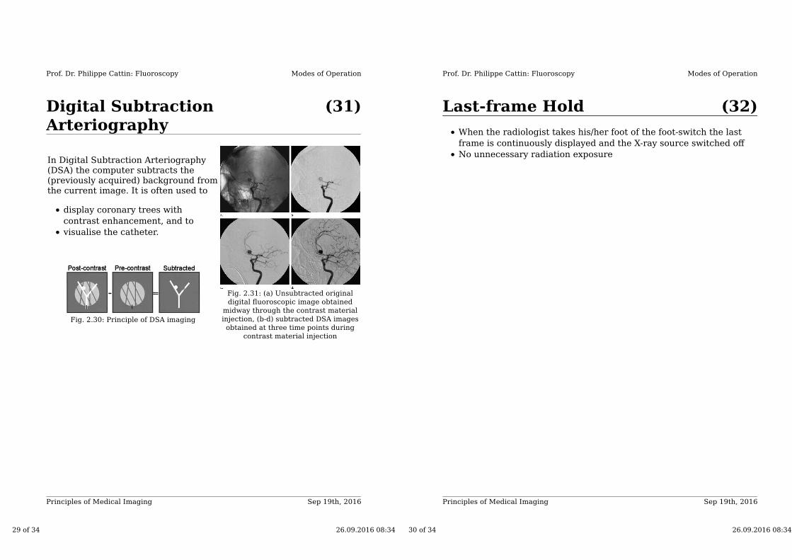
Digital SubtractionArteriography
In Digital Subtraction Arteriography(DSA) the computer subtracts the(previously acquired) background fromthe current image. It is often used to
display coronary trees with
contrast enhancement, and to
visualise the catheter.
Fig. 2.30: Principle of DSA imaging
Fig. 2.31: (a) Unsubtracted original
digital fluoroscopic image obtained
midway through the contrast material
injection, (b-d) subtracted DSA images
obtained at three time points during
contrast material injection
29 of 34 26.09.2016 08:34
Sep 19th, 2016Principles of Medical Imaging
Modes of Operation
(32)
Prof. Dr. Philippe Cattin: Fluoroscopy
Last-frame Hold
When the radiologist takes his/her foot of the foot-switch the last
frame is continuously displayed and the X-ray source switched off
No unnecessary radiation exposure
30 of 34 26.09.2016 08:34
Sep 19th, 2016Principles of Medical Imaging
Modes of Operation
(33)
Prof. Dr. Philippe Cattin: Fluoroscopy
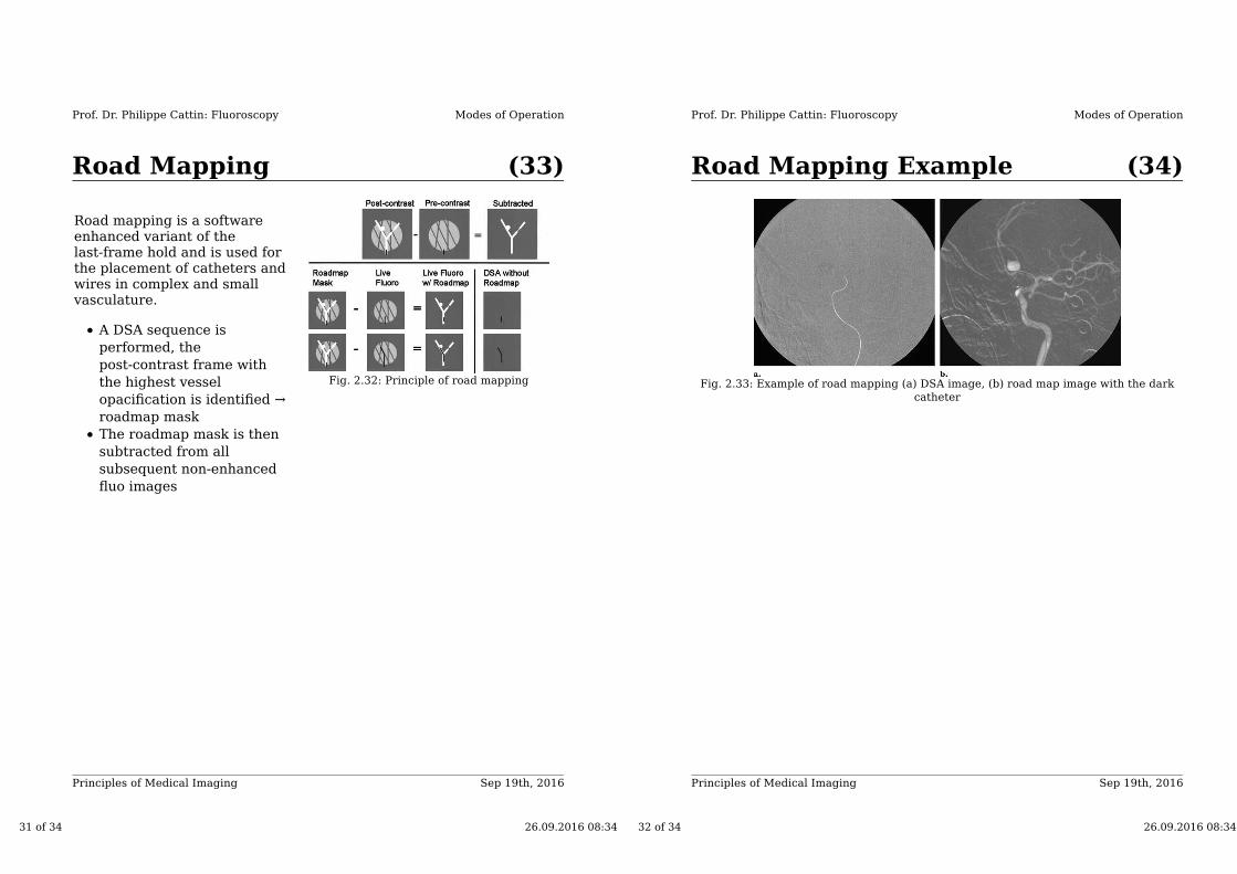
Road Mapping
Road mapping is a softwareenhanced variant of thelast-frame hold and is used forthe placement of catheters andwires in complex and smallvasculature.
A DSA sequence is
performed, the
post-contrast frame with
the highest vessel
opacification is identified →
roadmap mask
The roadmap mask is then
subtracted from all
subsequent non-enhanced
fluo images
Fig. 2.32: Principle of road mapping
31 of 34 26.09.2016 08:34
Sep 19th, 2016Principles of Medical Imaging
Modes of Operation
(34)
Prof. Dr. Philippe Cattin: Fluoroscopy
Road Mapping Example
Fig. 2.33: Example of road mapping (a) DSA image, (b) road map image with the dark
catheter
32 of 34 26.09.2016 08:34

Sep 19th, 2016Principles of Medical Imaging
Modes of Operation
(35)
Prof. Dr. Philippe Cattin: Fluoroscopy
Application of the Fluoroscopeon TEVAR
Fluoroscopy is an essential tool for Thoracic endovascular aortic repair(TEVAR), where aortic stents are placed in stenotic coronary arteries.
In TEVAR interventions, the Fluoroscope is used in several differentoperation modes:
The passage of guidewires, catheters, and sheaths are performed
under pulsed fluoroscopy
1.
Continuous fluoroscopy is used to shoot a arteriogram2.
Digital subtraction arteriography (DSA) allows to display the
contrast enhanced vasculature without the background
3.
Road mapping is used for real-time catheter guidance with a
contrast background acquired previously
4.
33 of 34 26.09.2016 08:34
FluoroscopyConclusion
Sep 19th, 2016Principles of Medical Imaging
(37)Fluoroscopy Conclusion
Fluoroscopes are most often used for
Intra-operative navigation
Intra-operative referencing
Target location
Problems
Very low contrast
Image noise
34 of 34 26.09.2016 08:34