Embed Size (px)
Citation preview
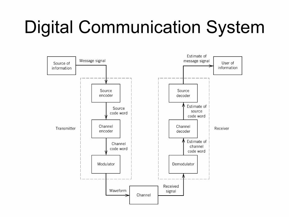
Digital Communication System

Source coding
• Represent signals into digital data (e.g. bits)– E.g. video, audio
• How to use as little amount of digital data as possible without losing any information
• How to use as little amount of digital data as possible with an acceptable loss of information (fidelity)
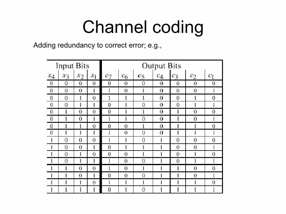
Channel codingAdding redundancy to correct error; e.g.,

Modulation
modulator channel demodulatorSourceSignal
Bit stream
Dest.
bit
+
n(t)
Converting bits to waveforms
e.g., Digital modulation

Intuitive picture
Naive
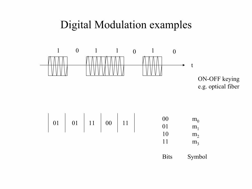
Digital Modulation examples
1 1 1 10 0 0
t
ON-OFF keyinge.g. optical fiber
01 01 11 00 1100 m001 m110 m211 m3
Bits Symbol
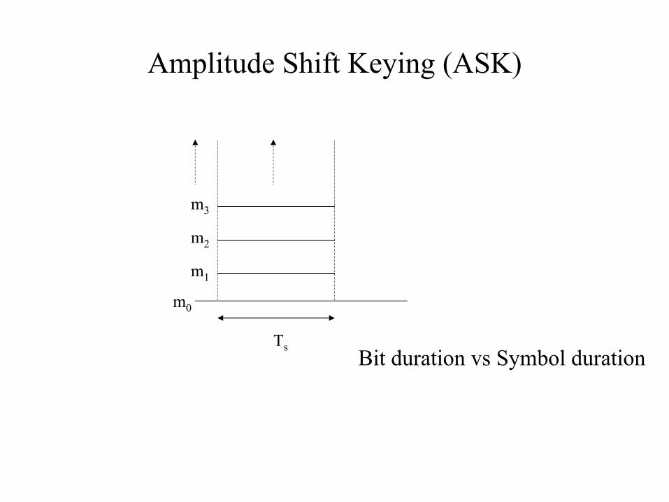
Amplitude Shift Keying (ASK)
Ts
m0
m1
m2
m3
Bit duration vs Symbol duration
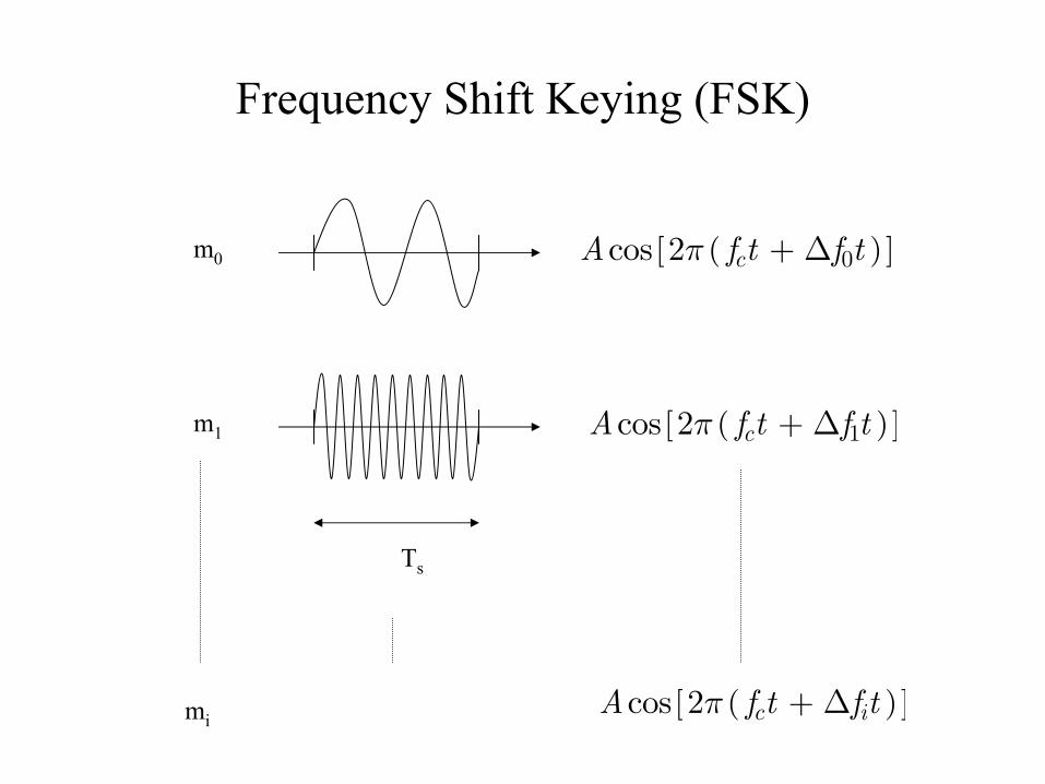
Frequency Shift Keying (FSK)
Ts
m0
m1
( )[ ]0cos 2 cA f t f tπ + ∆
( )[ ]1cos 2 cA f t f tπ + ∆
mi( )[ ]cos 2 c iA f t f tπ + ∆
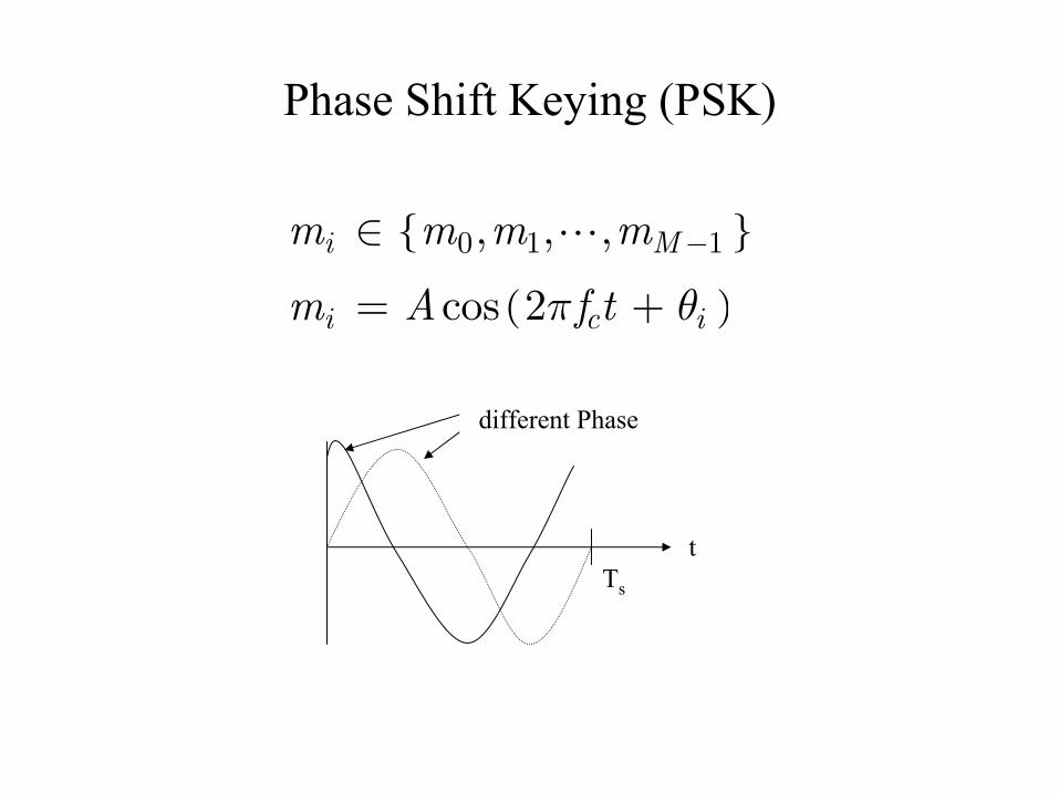
Phase Shift Keying (PSK)
{ }
( )
0 1 1, , ,
cos 2
i M
i c i
m m m m
m A f tπ θ
−∈
= +
tTs
different Phase
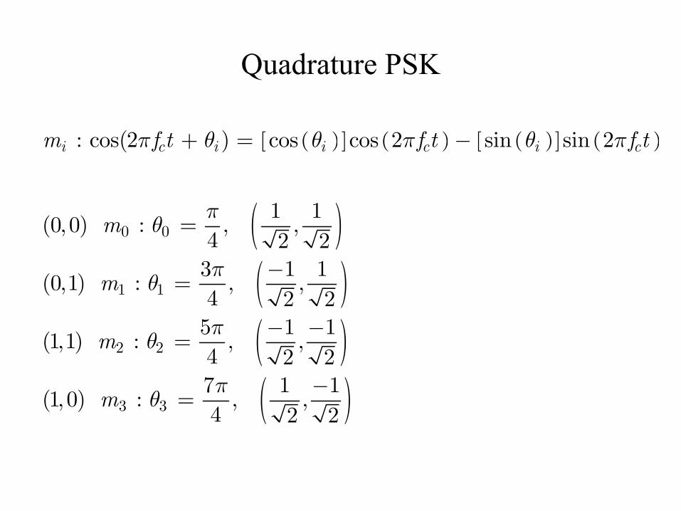
Quadrature PSK
( )[ ] ( ) ( )[ ] ( )
( )( )( )( )
0 0
1 1
2 2
3 3
: cos(2 ) cos cos 2 sin sin 2
1 1(0, 0) : , ,
4 2 23 1 1
(0,1) : , ,4 2 25 1 1
(1,1) : , ,4 2 27 1 1
(1, 0) : , ,4 2 2
i c i i c i cm f t f t f t
m
m
m
m
π θ θ π θ π
πθ
πθ
πθ
πθ
+ = −
=
−=
− −=
−=
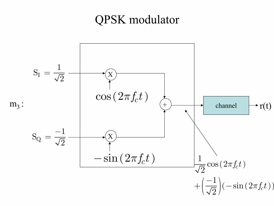
QPSK modulator
X
X
+ channel
I1
S2
=
Q1
S2
−=
( )cos 2 cf tπ
( )sin 2 cf tπ−
m3 :
( )
( ) ( )( )
1cos 2
21
sin 22
c
c
f t
f t
π
π−
+ −
r(t)

QPSK Demodulator
( )
0
sT
dt∫ i
( )
0
sT
dt∫ i
X
X
( )cos 2 cf tπ
( )sin 2 cf tπ−
( ) ( )
( )
( )
cos 2
sin 2
I c
Q c
r t S f t
S f t
n t
π
π
=
−
+
IS2s
IT
n+
QS2s
QT
n+
( ) ( )
( ) ( )( ) ( ) ( ) ( )2I Q
cos 2
S cos 2 +S sin 2 cos 2 cos 2
c
c c c c
r t f t
f t f t f t n t f t
π
π π π π= − +
1integer multiple of sc
T f=
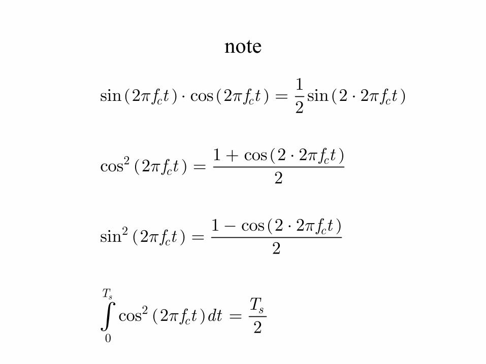
note
( ) ( ) ( )
( )( )
( )( )
( )
2
2
2
0
1sin 2 cos 2 sin 2 2
2
1 cos 2 2cos 2
2
1 cos 2 2sin 2
2
cos 22
s
c c c
cc
cc
Ts
c
f t f t f t
f tf t
f tf t
Tf t dt
π π π
ππ
ππ
π
⋅ = ⋅
+ ⋅=
− ⋅=
=∫

8PSK
001 110 101 111
000 m0001 m1
111 m7

I-Q representation of QPSK
( ) ( ) ( ) ( ) ( )( ): cos cos 2 sin sin 2i X i c i cm S t f t f tθ π θ π= + −
( )( )( )( )
0
1
2
3
1 1: ,
2 21 1
: ,2 21 1
: ,2 21 1
: ,2 2
m
m
m
m
−
− −
−
m0m1
m3m2
12
12
( )cos 2 cf tπ
( )sin 2 cf tπ−
In-phasecomponent
Quadrature-phasecomponent

I-Q representation of 8PSK
m0
m1
m4
m3
12
( )cos 2 cf tπ
( )sin 2 cf tπ−
In-phasecomponent
Quadrature-phasecomponent
m2
m5
m6
m7
“Symbol constellation”“Signal constellation”
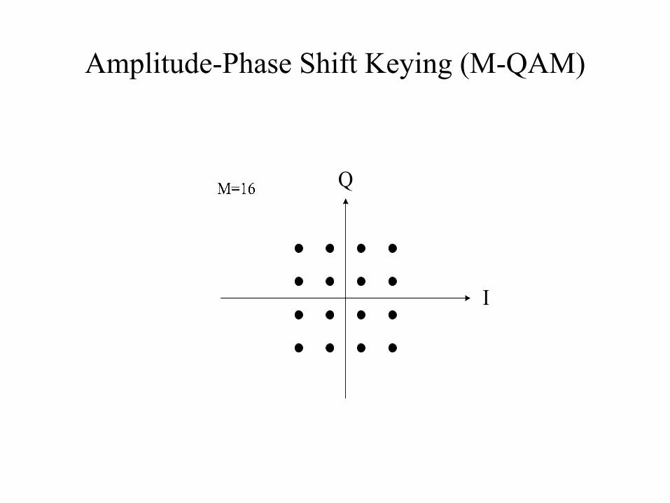
Amplitude-Phase Shift Keying (M-QAM)

Carrier acquisition and tracking
• Carrier frequency can drift.• Moreover, there is a Doppler effect in
mobile stations.
Symbol time synchronization and phase coherency
• It is done on the basis of the discontinuity of the waveforms between adjacent symbols.
• If there is no channel distortion, the delineated boundary between symbols and the shape of the waveform would give the phase of the waveforms for each symbol
• In real-life there is distortion, so the phase information is not given even if the symbol interval is delineated. For coherent detection, the phase information must be provided through additional circuits.

Imperfect Channel and Noise
• E.g. Pair of copper wire, coaxial cable, optical fiber, wireless channel
Band-limited channel
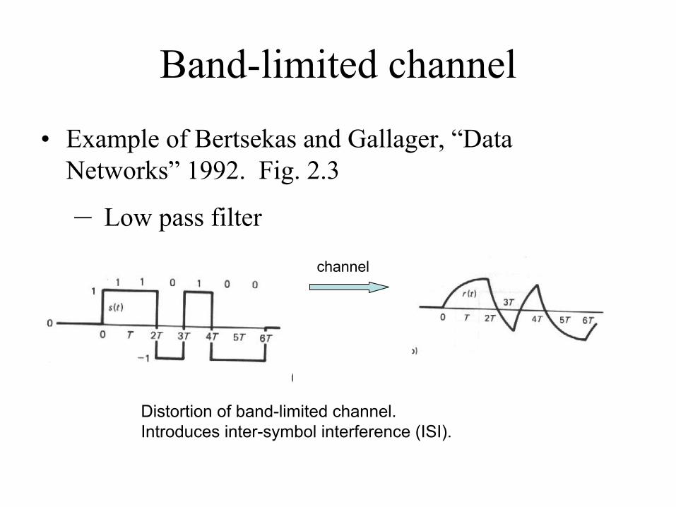
• Example of Bertsekas and Gallager, “Data Networks” 1992. Fig. 2.3
– Low pass filter
channel
Distortion of band-limited channel.Introduces inter-symbol interference (ISI).

Note
A rectangular wave’s bandwidth is large.The band-limited channel clips the high-frequency component of the signal.
Channel model
• Channel take input signals and gives rise to output signals; can be viewed as a “system” or “filter”.
Inter Symbol Interference (ISI)
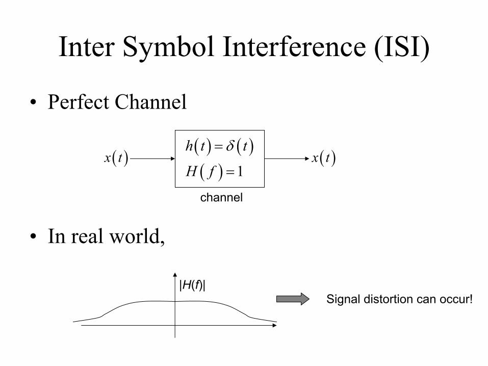
• Perfect Channel
( ) ( )( ) 1
h t t
H f
δ=
=( )x t ( )x t
channel
• In real world,
|H(f)|Signal distortion can occur!
Inter Symbol Interference (ISI)
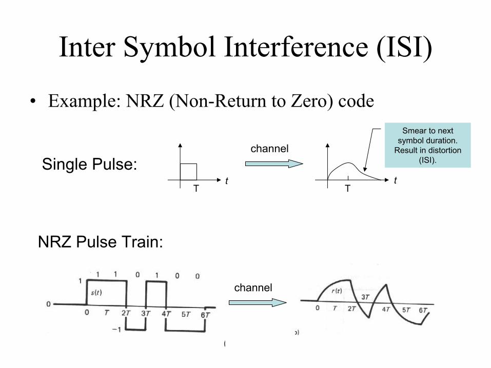
• Example: NRZ (Non-Return to Zero) code
t
channel
tT T
Single Pulse:
Smear to next symbol duration.
Result in distortion (ISI).
channel
NRZ Pulse Train:

Same story (distortion) in the pass-band signal.
1 1 1 10 0 0
t
ASK
f
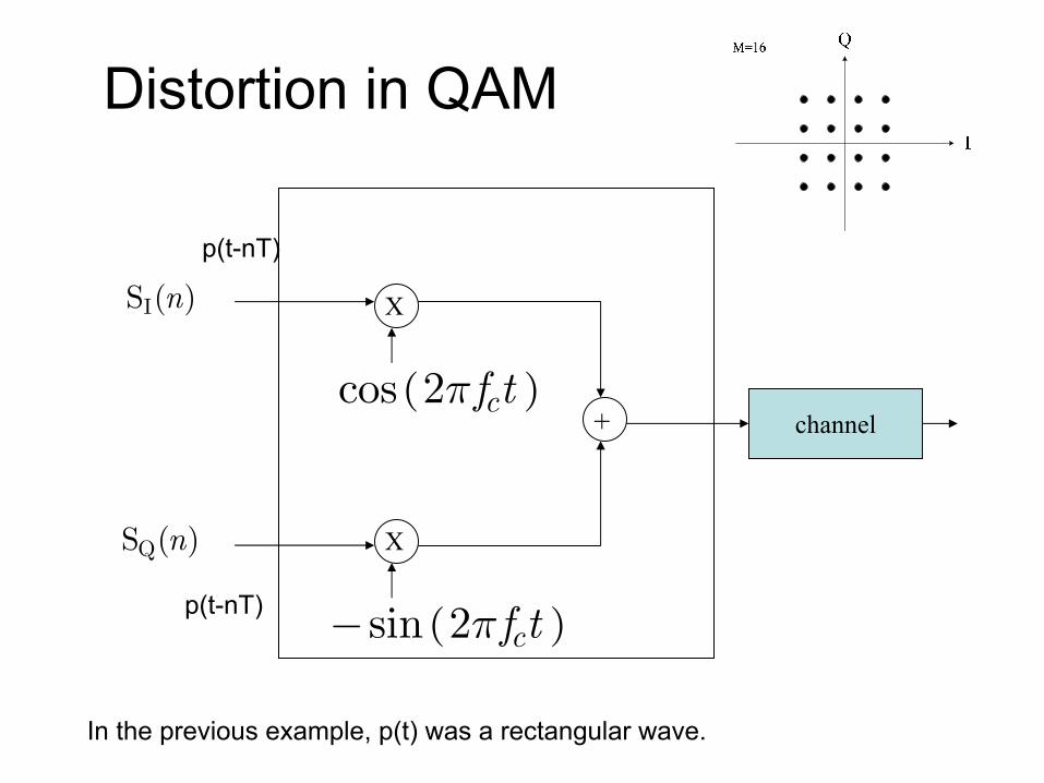
Distortion in QAM
X
X
+ channel
IS ( )n
QS ( )n
( )cos 2 cf tπ
( )sin 2 cf tπ−
p(t-nT)
p(t-nT)
In the previous example, p(t) was a rectangular wave.

f
Theoretical guidance: Nyquistpulse
• In fact, by designing p(t) to be other than the rectangular pulse and designing a receiver filter, one can avoid ISI.

• Solution to ISI: Equalizer
H(f)
Channel Receiver
Equalizer
S(t) S(t)
In real world, delay is considered: S(t-d)
H-1(f) as an equalizer?Noise is greatly amplified at frequencies with low |H(f)|.